- Manuals
- Brands
- Talgil Manuals
- Controller
- FILTRON 1-10 DC
- User manual
-
Bookmarks
Quick Links
TALGIL
Computing & Control Ltd.
ISRAEL
TALGIL COMPUTING & CONTROL LTD.
NAAMAN CENTER, HAIFA — ACCO ROAD 7000
P.O.BOX 775 KIRYAT MOTZKIN 26119, ISRAEL
TEL: 972-4-8775947; 972-4-8775948
FAX: 972-4-8775949
E-mail: talgil33@netvision.net.il
FILTRON
1-10 (DC/AC)
U S E R ‘ S
M A N U A L
2011
Related Manuals for Talgil FILTRON 1-10 DC
Summary of Contents for Talgil FILTRON 1-10 DC
- Page 1
TALGIL Computing & Control Ltd. ISRAEL TALGIL COMPUTING & CONTROL LTD. NAAMAN CENTER, HAIFA — ACCO ROAD 7000 P.O.BOX 775 KIRYAT MOTZKIN 26119, ISRAEL TEL: 972-4-8775947; 972-4-8775948 FAX: 972-4-8775949 E-mail: talgil33@netvision.net.il FILTRON 1-10 (DC/AC) U S E R ‘ S… -
Page 2: List Of Features
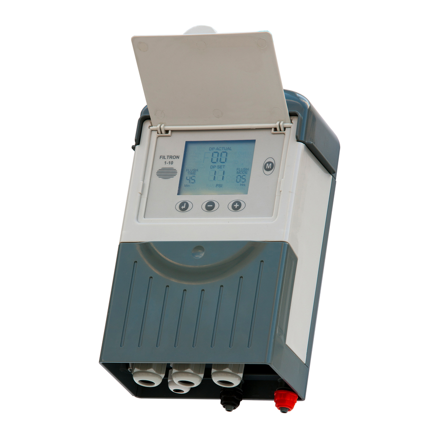
FILTRON 1-10 (DC/AC) List of features The “FILTRON 1-10” is a modular backflushing controller for automatic filters of 1 to 10 stations. There exist DC and AC models. The DC model can be powered either by 6v DC or 12v DC and it activates 2 wired 12v DC latching solenoids.
- Page 3
How to program the controller The controller is equipped with an LCD display and 4 keys as displayed below. When the unit is left untouched for a minute the display is switched off and the only life signal is given by a beep sound that can be heard every 20 seconds. - Page 4
The Flush Time Defines the duration of the flushing time per station. The following options are selectable: 5-20 sec in steps of 1 sec 20-55 sec in steps of 5 sec min in steps of 0.5 min The DP Set Point At this field the user defines the pressure difference between the filter’s inlet and outlet that when reached, a flushing cycle will take place. - Page 5
The unit will detect how many “plug-in” boards (each of 2 outputs) are used in the particular case. How will the outputs be allocated depends on the definitions made during the configuration process described below. The following rules apply: Backflush valves will be allocated starting from output 1 and up. The last backflush valve can be canceled and then its allocated output will be left unused. - Page 6
Handling Endless Looping problems As explained above, endless looping problem will be declared when the number of consecutive flushing cycles triggered by the DP sensor exceeds the “Looping limit” defined during configuration. The fact that endless looping problem was detected will be indicated on the display and will cause the activation of the Alarm output, additionally, the DP indication will no longer be considered as a trigger for flushing. -
Page 7: Timing Diagram
Timing Diagram Without Delay Valve Main valve Flush time Dwell Valve 1 Dwell time Valve 2 Valve 3 Valve 4 Including Delay Valve Main valve Dwell Valve 1 Dwell time Valve 2 Valve 3 Valve 4 Flush time Delay valve Valve Delay…
-
Page 8: Wiring Diagram
Wiring Diagram DC MODEL The drawing below shows the wiring of the DC model of the controller. Notice that: The External DP sensor is optional and it is intended for use in cases there is no Embedded Electronic DP included. The powering of the unit can be either by 6v DC or 12v DC.
- Page 9
AC MODEL The drawing below shows the wiring of the AC model of the controller. Notice that: The External DP sensor is optional and it is intended for use in cases there is no Embedded Electronic DP included. The powering of the unit is by 24VAC transformed from 220/110 VAC. The solenoids will be of 24VAC. -
Page 10: Technical Data
TECHNICAL DATA DC MODEL 6v supplied by 4 x 1.5 “D” size alkaline batteries. Power source: or 12v DC dry battery or 12v rechargeable battery with solar panel of 2 watts Outputs : 12v DC latching solenoids. Embedded electronic analog DP sensor or external dry contact DP sensor.
ISRAEL
TALGIL COMPUTING & CONTROL LTD.
NAAMAN CENTER, HAIFA — ACCO ROAD 7000
P.O.BOX 775 KIRYAT MOTZKIN 26119, ISRAEL
TEL: 972-4-8775947; 972-4-8775948
FAX: 972-4-8775949
E-mail: talgil33@netvision.net.il
FILTRON
1-10 (DC/AC)
РУКОВОДСТВО ПОЛЬЗОВАТЕЛЯ
2011
1
FILTRON 1-10 (DC/AC)
Основные функции
“FILTRON 1-10” это модульный (на 2, 4, 6, 8 или 10 выходов) контроллер для промывки
батарей автоматических фильтров, состоящих из 1 – 10 фильтров.
Существуют модели переменного (AC) и постоянного (DC) тока.
Модели постоянного тока могут питаться напряжением 6 или 12 вольт, и предназначены
для управления 2-х проводными 12-ти вольтовыми соленоидами-защёлками (LATCH).
Модели переменного тока имеют встроенный блок питания, который может быть
подключен к сети с напряжением 220 или 110 вольт и который понижает напряжение до
24
вольт для управления соленоидами.
Цикл промывки может быть запущен по времени или когда разность давлений,
измеренная встроенным электронным датчиком DP, достигает заданного значения или
по замыканию контакта внешнего датчика разности давлений. Возможен также ручной
запуск.
Контроллер производит обнаружение неисправности «Бесконечная промывка» если
количество непрерывных промывок по DP превышает заранее заданное значение.
Контроллер может управлять Главным Краном, Клапаном Задержки и устройством
Сигнализации.
Контроллер снабжён специальным ЖК-дисплеем и клавиатурой.
How to program the controller
The controller is equipped with an LCD display and 4 keys as displayed below. When the unit is left
untouched for a minute the display is switched off and the only life signal is given by a beep sound that
can be heard every 20 seconds. Holding down any of the keys for a few seconds will bring the screen
back to life.
The Actual DP value.
Available only when
the built in electronic
DP is used
The desired flushing
time per station
The screen consists of several fields, some of them are editable and some of them are not. For
inserting EDIT MODE the ENTER key has to be pushed. The EDIT MODE is indicated by blinking of
the characters at the currently editable field. Each time the ENTER key is pushed again, the next
editable field becomes under focus and starts blinking. While in EDIT MODE the «+» and «-» keys can
be used for changing the value under focus. Pushing the ENTER key again will set the selected value
to the current field and move the focus to the next editable field which will start blinking. Once entering
this process of passing through the editable fields, the user has no way back but by pushing the
ENTER key repeatedly, he passes through the chain of editable fields until arriving back to the FLUSH
TIME field, meeting no more blinking fields.
REMARK
The chain of editable fields
Following is the chain of editable fields. The existence of the DP SET-POINT field depends on whether
the system contains a built-in electronic DP or not.
FLUSH
TIME
ACCUMULATIONS
DP
—
ENTER
Notice that before the first use of the unit, it may be necessary to pass through
the configuration process prior to defining the flushing program in order to
adjust the features of controller to the specific application. The configuration
process is described below.
DP SET-
FLUSH
POINT
MODE
ACCUMULATIONS
TIME
+
ACCUMULATIONS
MANUAL
2
The DP Set-Point.
Available only when
the built in electronic
DP is used
MANUAL
The desired flushing
mode. Contains either the
flushing interval or the
letters «dp» when the
flushing is triggered by
dp only.
TALGIL и отвечает всем требованиям для управления промывкой фильтров, дешев и прост в эксплуатации.“FILTRON 246” выпускается в трех модификациях, на 2, 4 и 6 выходов.
Прибор может питаться от источника постоянного тока (DC) или от источника переменного тока (АС). Приборы DC питаются от внутренней сухой батареи 12V, приборы АС от встроенного трансформатора 24 V. Выбор программы промывки производится двумя круговыми переключателями, расположенными в середине панели. Установка пауз и длительности промывки фильтров производится переключателем DIP SWITCH, находящемся внутри прибора. Имеется возможность заказа прибора со счетчиком, подсчитывающим количество циклов промывки.
ТЕХНИЧЕСКАЯ ХАРАКТЕРИСТИКА
• Приборы DC или AC;
• Выполнение промывки по команде дифференциального манометра;
• Выполнение промывки по команде дифференциального манометра и/или по времени цикла
Параметры режима работы включают в себя:
1. Выбор способа работы: включение вручную; только по сигналу дифференциального манометра (DP), работа по сигналу DP и/или по времени ;
2. Выбор времени между промывками;
3. Выбор продолжительности промывки каждого фильтра;
4. Выбор времени паузы между промывкой отдельных фильтров;
5. Выбор времени задержки реакции на изменение состояния DP;
6. Выбор количества непрерывно повторяющихся циклов промывки по DP, для определения неисправности DP.
ВНЕШНИЙ ВИД ПАНЕЛИ УПРАВЛЕНИЯ

Table of Contents for Talgil FILTRON 1-10 DC:
-
3 The Flush Time Defines the duration of the flushing time per station. The following options are selectable: 5-20 sec in steps of 1 sec 20-55 sec in steps of 5 sec 1-6 min in steps of 0.5 min The DP Set Point At this field the user defines the pressure difference between the filter’s inlet and outlet that when reached, a flushing cycle will take place. This field is meaningless
-
6 Main valve Valve 1 Valve 2 Pre Dwell Flush time Valve 3 Valve 4 Dwell time Main valve Valve 1 Valve 2 Pre Dwell Flush time Valve 3 Valve 4 Delay valve Dwell time V V Valve Delay Timing Diagram Without Delay Valve Including Delay Valve
-
9 TECHNICAL DATA DC MODEL Power source: 6v supplied by 4 x 1.5 “D” size alkaline batteries. or 12v DC dry battery or 12v rechargeable battery with solar panel of 2 watts Outputs : 12v DC latching solenoids. DP: Embedded electronic analog DP sensor or external dry contact DP sensor. Pressure Sensor: Dry contact pressure sensor Operating temperature: 0-60 C. AC MODEL Power source: 220
-
1 FILTRON 1-10 (DC/AC) List of features The “FILTRON 1-10” is a modular backflushing controller for automatic filters of 1 to 10 stations. There exist DC and AC models. The DC model can be powered either by 6v DC or 12v DC and it activates 2 wired 12v DC latching solenoids. The voltage for the solenoids switching is boosted by a charge pump. The AC model contains an internal transformer that can be powered by 110v or 220v from which it
-
8 AC MODEL The drawing below shows the wiring of the AC model of the controller. Notice that: 1. The External DP sensor is optional and it is intended for use in cases there is no Embedded Electronic DP included. 2. The powering of the unit is by 24VAC transformed from 220/110 VAC. 3. The solenoids will be of 24VAC. Make sure to DISCONNECT the POWER before inserting / removing the 2 ouputs plug-in unit.
-
2 How to program the controller The controller is equipped with an LCD display and 4 keys as displayed below. When the unit is left untouched for a minute the display is switched off and the only life signal is given by a beep sound that can be heard every 20 seconds. Holding down any of the keys for a few seconds will bring the screen back to life. ENTER +- MANUAL The screen
-
7 Wiring Diagram DC MODEL The drawing below shows the wiring of the DC model of the controller. Notice that: 1. The External DP sensor is optional and it is intended for use in cases there is no Embedded Electronic DP included. 2. The powering of the unit can be either by 6v DC or 12v DC. 3. The solenoids will be of 12VDC latch.
-
5 Handling Endless Looping problems As explained above, endless looping problem will be declared when the number of consecutive flushing cycles triggered by the DP sensor exceeds the “Looping limit” defined during configuration. The fact that endless looping problem was detected will be indicated on the display and will cause the activation of the Alarm output, additionally, the DP indication will no longer be considered as a trigger for flushing. Th
-
4 The unit will detect how many “plug-in” boards (each of 2 outputs) are used in the particular case. How will the outputs be allocated depends on the definitions made during the configuration process described below. The following rules apply: 1. Backflush valves will be allocated starting from output 1 and up. 2. The last backflush valve can be canceled and then its allocated output will be left unused. 3. Alarm output, Delay-Valve and Main-Valve when
Questions, Opinions and Exploitation Impressions:
You can ask a question, express your opinion or share our experience of Talgil FILTRON 1-10 DC device using right now.
- Manuals
- Brands
- Talgil Manuals
- Controller
- FILTRON 1-10 DC
- User manual
-
Bookmarks
Quick Links
TALGIL
Computing & Control Ltd.
ISRAEL
TALGIL COMPUTING & CONTROL LTD.
NAAMAN CENTER, HAIFA — ACCO ROAD 7000
P.O.BOX 775 KIRYAT MOTZKIN 26119, ISRAEL
TEL: 972-4-8775947; 972-4-8775948
FAX: 972-4-8775949
E-mail: talgil33@netvision.net.il
FILTRON
1-10 (DC/AC)
U S E R ‘ S
M A N U A L
2011
Related Manuals for Talgil FILTRON 1-10 DC
Summary of Contents for Talgil FILTRON 1-10 DC
-
Page 1
TALGIL Computing & Control Ltd. ISRAEL TALGIL COMPUTING & CONTROL LTD. NAAMAN CENTER, HAIFA — ACCO ROAD 7000 P.O.BOX 775 KIRYAT MOTZKIN 26119, ISRAEL TEL: 972-4-8775947; 972-4-8775948 FAX: 972-4-8775949 E-mail: talgil33@netvision.net.il FILTRON 1-10 (DC/AC) U S E R ‘ S… -
Page 2: List Of Features
FILTRON 1-10 (DC/AC) List of features The “FILTRON 1-10” is a modular backflushing controller for automatic filters of 1 to 10 stations. There exist DC and AC models. The DC model can be powered either by 6v DC or 12v DC and it activates 2 wired 12v DC latching solenoids.
-
Page 3
How to program the controller The controller is equipped with an LCD display and 4 keys as displayed below. When the unit is left untouched for a minute the display is switched off and the only life signal is given by a beep sound that can be heard every 20 seconds. -
Page 4
The Flush Time Defines the duration of the flushing time per station. The following options are selectable: 5-20 sec in steps of 1 sec 20-55 sec in steps of 5 sec min in steps of 0.5 min The DP Set Point At this field the user defines the pressure difference between the filter’s inlet and outlet that when reached, a flushing cycle will take place. -
Page 5
The unit will detect how many “plug-in” boards (each of 2 outputs) are used in the particular case. How will the outputs be allocated depends on the definitions made during the configuration process described below. The following rules apply: Backflush valves will be allocated starting from output 1 and up. The last backflush valve can be canceled and then its allocated output will be left unused. -
Page 6
Handling Endless Looping problems As explained above, endless looping problem will be declared when the number of consecutive flushing cycles triggered by the DP sensor exceeds the “Looping limit” defined during configuration. The fact that endless looping problem was detected will be indicated on the display and will cause the activation of the Alarm output, additionally, the DP indication will no longer be considered as a trigger for flushing. -
Page 7: Timing Diagram
Timing Diagram Without Delay Valve Main valve Flush time Dwell Valve 1 Dwell time Valve 2 Valve 3 Valve 4 Including Delay Valve Main valve Dwell Valve 1 Dwell time Valve 2 Valve 3 Valve 4 Flush time Delay valve Valve Delay…
-
Page 8: Wiring Diagram
Wiring Diagram DC MODEL The drawing below shows the wiring of the DC model of the controller. Notice that: The External DP sensor is optional and it is intended for use in cases there is no Embedded Electronic DP included. The powering of the unit can be either by 6v DC or 12v DC.
-
Page 9
AC MODEL The drawing below shows the wiring of the AC model of the controller. Notice that: The External DP sensor is optional and it is intended for use in cases there is no Embedded Electronic DP included. The powering of the unit is by 24VAC transformed from 220/110 VAC. The solenoids will be of 24VAC. -
Page 10: Technical Data
TECHNICAL DATA DC MODEL 6v supplied by 4 x 1.5 “D” size alkaline batteries. Power source: or 12v DC dry battery or 12v rechargeable battery with solar panel of 2 watts Outputs : 12v DC latching solenoids. Embedded electronic analog DP sensor or external dry contact DP sensor.
Download Operation & user’s manual of Talgil FILTRON 1-10 AC Controller for Free or View it Online on All-Guides.com.

ISRAEL
TALGIL COMPUTING & CONTROL LTD.
NAAMAN CENTER, HAIFA — ACCO ROAD 7000
P.O.BOX 775 KIRYAT MOTZKIN 26119, ISRAEL
TEL: 972-4-8775947; 972-4-8775948
FAX: 972-4-8775949
FILTRON
1-10 (DC/AC)
U S E R ‘ S M A N U A L
2011
TALGIL
Computing & Control Ltd.
Specifications:1323/1323625-filtron_110_dc.pdf file (05 Jun 2023) |
Accompanying Data:
Talgil FILTRON 1-10 DC Controller PDF Operation & User’s Manual (Updated: Monday 5th of June 2023 10:50:53 AM)
Rating: 4.1 (rated by 14 users)
Compatible devices: 2681022, TECHLINE LA37, Relion 620 Series, SA Series, BERMAD Irrigation BIC 1000 DC, HGM7100N Series, 2469, DSE5510.
Recommended Documentation:
Text Version of Operation & User’s Manual
(Ocr-Read Summary of Contents of some pages of the Talgil FILTRON 1-10 DC Document (Main Content), UPD: 05 June 2023)
-
6, 5 Handling Endless Looping problems As explained above, endless looping problem will be declared when the number of consecutive flushing cycles triggered by the DP sensor exceeds the “Looping limit” defined during configuration. The fact that endless looping…
-
7, Talgil FILTRON 1-10 DC 6 Main valve Valve 1 Valve 2 Pre Dwell Flush time Valve 3 Valve 4 Dwell time Main valve Valve 1 Valve 2 Pre Dwell Flush time Valve 3 Valve 4 Delay valve Dwell time V V Valve Delay Timing Diagram Without Delay Valve …
-
10, Talgil FILTRON 1-10 DC 9 TECHNICAL DATA DC MODEL Power source: 6v supplied by 4 x 1.5 “D” size alkaline batteries. or 12v DC dry battery or 12v rechargeable battery with solar panel of 2 watts Outputs : 12v DC latching solenoids. DP: Embedded electronic anal…
-
3, 2 How to program the controller The controller is equipped with an LCD display and 4 keys as displayed below. When the unit is left untouched for a minute the display is switched off and the only life signal is given by a beep sound that can be heard every 20 seconds. Holding down an…
-
1, Talgil FILTRON 1-10 DC ISRAEL TALGIL COMPUTING & CONTROL LTD. NAAMAN CENTER, HAIFA — ACCO ROAD 7000 P.O.BOX 775 KIRYAT MOTZKIN 26119, ISRAEL TEL: 972-4-8775947; 972-4-8775948 FAX: 972-4-8775949 E-mail: [email protected] FILTRON 1-10 (DC/AC) U S E R ‘ S M A N U A L 2011 TALGIL …
-
2, 1 FILTRON 1-10 (DC/AC) List of features The “FILTRON 1-10” is a modular backflushing controller for automatic filters of 1 to 10 stations. There exist DC and AC models. The DC model can be powered either by 6v DC or 12v DC and it activates 2 wired 12v DC latching solenoi…
-
Talgil FILTRON 1-10 DC User Manual
-
Talgil FILTRON 1-10 DC User Guide
-
Talgil FILTRON 1-10 DC PDF Manual
-
Talgil FILTRON 1-10 DC Owner’s Manuals
Recommended: POWER WHEELS 74780, FinePixA204, G 12VA


-
sysmik ICS-852M
SysMik GmbH Dresden Bertolt-Brecht-Allee 24 01309 Dresden Germany Tel.: +49(0) 351 433 58 -0 Fax: +49(0) 351 433 58 -29 www.sysmik.de [email protected] InlineControlServer ICS-852M | Art.-Nr.: 1226-100202-04-8 ICS-709M-B | Art.-Nr.: 1226-100202-08-6ICS-852MX | Art.-Nr.: 1226-100202-05-5 DE …
ICS-852M 2
-
Popp Flow Stop 2
Flow Stop 2 user guideModified on: Thu, 25 Jun, 2020 at 12:48 AMPopp Flow Stop 2.Popp Flow Stop (https://www.popp.eu/products/actuators/flow-stop/) 2 was developed to close valves in case of alarm viaZ-Wave. It is powered by Popp (https://www.popp.eu/products/) (http://aeotec.com/z-wave-gen5)technology. Before purcha …
Flow Stop 2 4
-
Mitsubishi G-50A
G-50AON/OFFCENTRAL CONTROLLERMitsubishi Electric Air-conditioner Network SystemCentral ControllerModel: G-50AInstallation ManualBefore using the controller, please read this Installation Manual carefully to ensurecorrect operation. Store this Installation Manual in a location that is easy to find.Contents1. Safety …
G-50A 12
-
ICP DAS USA 7188XA
� …
7188XA 80
Additional Information:
Popular Right Now:
Operating Impressions, Questions and Answers:
Подпишитесь на информационный бюллетень
- Самая свежая информация о продуктах
- Доступ к уникальному содержанию
Закрыть
-
НАЙТИ ФИЛЬТР
-
НАЙТИ ДИСТРИБЬЮТОРА
-
АКАДЕМИЯ FILTRON
-
ПРОДУКТЫ
- ВОЗДУШНЫЕ ФИЛЬТРЫ
- МАСЛЯНЫЕ ФИЛЬТРЫ
- ТОПЛИВНЫЕ ФИЛЬТРЫ
- САЛОННЫЕ ФИЛЬТРЫ
- ДРУГИЕ ФИЛЬТРЫ
- ОТВЕТСТВЕННОСТЬ ЗА КАЧЕСТВО
- Protect+
-
КОМПАНИЯ
- ПОЗНАКОМЬТЕСЬ С НАМИ
- НОВОСТИ
- ФАЙЛЫ ДЛЯ ЗАГРУЗКИ
- КОНТАКТ
-
ПОДДЕРЖКА
- СОВЕТЫ ДЛЯ МЕХАНИКОВ
- ИНСТРУКЦИИ ПО УСТАНОВКЕ
- FAQ
-
Benefit program
- Russian
- Belarussian
- Moldovian


+
© 2017 by MANN+HUMMEL FT Poland. All rights reserved.
MANN+HUMMEL FT Poland Spółka z ograniczoną odpowiedzialnością Sp. k.
ul. Wrocławska 145, 63-800 GOSTYŃ, POLAND