-
Contents
-
Table of Contents
-
Bookmarks
Quick Links
123B/124B/125B
®
Industrial ScopeMeter
Test Equipment Depot — 800.517.8431 — 99 Washington Street Melrose, MA 02176 — TestEquipmentDepot.com
Users Manual
January 2016
© 2016 Fluke Corporation. All rights reserved. Specifications are subject to change without notice.
All product names are trademarks of their respective companies.
Related Manuals for Fluke 123B
Summary of Contents for Fluke 123B
-
Page 1
Test Equipment Depot — 800.517.8431 — 99 Washington Street Melrose, MA 02176 — TestEquipmentDepot.com Users Manual January 2016 © 2016 Fluke Corporation. All rights reserved. Specifications are subject to change without notice. All product names are trademarks of their respective companies. -
Page 2
LIMITED WARRANTY AND LIMITATION OF LIABILITY Each Fluke product is warranted to be free from defects in material and workmanship under normal use and service. The warranty period is three years and begins on the date of shipment. Parts, product repairs, and services are warranted for 90 days. This warranty extends only to the original buyer or end-user customer of a Fluke authorized reseller, and does not apply to fuses, disposable batteries, or to any product which, in Fluke’s opinion, has been misused, altered, neglected, contaminated, or damaged by accident or abnormal conditions of operation or handling. -
Page 3: Table Of Contents
Table of Contents Title Page Introduction ……………………1 How to Contact Fluke ………………… 1 Safety Information ………………….1 Test Tool Kit Contents ………………..5 Get Started ……………………7 Battery Pack ………………….7 Mains Power Source ………………..8 SD Memory Cards ………………… 8 Test Tool Setup ………………….
-
Page 4
123B/124B/125B Users Manual Measurement Probe Setup ………………11 Tilt Stand ……………………12 Hanger ……………………12 Language Selection ………………..12 Scope and Meter Mode ………………..13 How to Read the Screen ………………. 14 Connect-and-View™ ………………..15 Measurements ………………….15 Inputs ……………………19 Voltage Measurements ……………… -
Page 5
Contents (continued) Single Acquisition ………………..27 Slow Signals ………………….28 AC Coupling………………….29 Waveform Trigger …………………. 29 Set Trigger Level and Slope …………….. 29 Select Trigger Parameters ………………30 Cursor Measurements ………………..32 Horizontal Cursors ………………..32 Vertical Cursors ………………..33 Rise Time Measurements ……………… -
Page 6
123B/124B/125B Users Manual Data Set Management ………………..57 Waveform Comparison ………………… 58 Communication ………………….59 Optical Interface ………………….59 Wireless Interface ………………… 59 Maintenance ……………………61 How to Clean ………………….61 Storage ……………………61 Battery Replacement ………………..61 10:1 Scope Probes ………………..62 Calibration Information ……………….. -
Page 7
List of Tables Table Title Page Symbols ……………………..4 Packing List ……………………… 5 Parts of the Screen …………………… 14 Volt/Amp Readings …………………… 37 Watt Readings ……………………37 Harmonics Voltage Measurements ………………39 Harmonics Current Measurements ………………40 Harmonics Power Measurements ………………41 Bus Measurement Inputs………………….. -
Page 8
123B/124B/125B Users Manual… -
Page 9: List Of Figures
List of Figures Figure Title Page Test Tool Kit …………………….. 6 Battery Charging ……………………7 Power Up/Reset Screen ………………….9 Input Connections for Measurement ………………11 Tilt Stand and Hanger ………………….12 Auto Set Function ……………………15 Measurement Setup ………………….16 Correct Grounding Setup …………………..
-
Page 10
123B/124B/125B Users Manual viii… -
Page 11: Introduction
Introduction ® The 123B/124B/125B ScopeMeter (the Test Tool or Product) is an integrated Test Tool, with oscilloscope, multimeter, and ‘paperless’ recorder in one easy-to-use instrument. Safety Information A Warning identifies hazardous conditions and procedures that are dangerous to the user.
-
Page 12
123B/124B/125B Users Manual • • Do not apply more than one phase of a Limit operation to the specified multiphase system simultaneously to measurement category, voltage, or any COM ˜ (common) connection. All amperage ratings. Common (COM) connections should be •… -
Page 13
Industrial ScopeMeter® Safety Information • • Do not use the Product if it operates Do not exceed the Measurement incorrectly. Category (CAT) rating of the lowest rated individual component of a Product, • Examine the case before you use the probe, or accessory. -
Page 14: Symbols
This product contains a Lithium-ion battery. Do not mix with solid waste stream. Spent batteries should be disposed of by a qualified recycler or hazardous materials handler per local regulations. Contact your authorized Fluke Service Center for recycling information. This product complies with the WEEE Directive marking requirements. The affixed label indicates that you must not discard this electrical/electronic product in domestic household waste.
-
Page 15: Test Tool Kit Contents
Table 2 is a list of the items included in your Test Tool kit. Also see Figure 1. Table 2. Packing List Item Description 12x-B 12x-B/S Fluke Test Tool 123B, 124B or 125B 123B/S, 124B/S or 125B/S • • Rechargeable Li-ion Battery Pack • • Switch Mode Power Supply, Adapter/Battery Charger …
-
Page 16
123B/124B/125B Users Manual S-Version (2x) (2x) 12345 — 12345 — 12345 hxv01.eps Figure 1. Test Tool Kit… -
Page 17: Get Started
Industrial ScopeMeter® Get Started Get Started Note The power adapter does not damage the Test Before you use your Test Tool for the first time, read this Tool even when connected over consecutive section. days. The power adapter automatically switches Battery Pack to a trickle charge.
-
Page 18: Mains Power Source
Users Manual Alternatively, you may choose to exchange the battery Mains Power Source (Fluke accessory BP290) with a fully charged one and To use the mains power source: use the external battery charger EBC290 (optional Fluke Attach the power cord to the mains power.
-
Page 19: Test Tool Setup
Industrial ScopeMeter® Test Tool Setup Test Tool Setup This section explains the basics for how to use your Test Tool. Reset the Test Tool To restore the Test Tool to the factory default settings: Push and hold + . Release .
-
Page 20: Screen Brightness
123B/124B/125B Users Manual Screen Brightness Menu Selection By default the display is at the brightest setting. To extend The buttons on the keypad provide the navigation through the battery life, you can decrease the brightness setting. the functions you see on the display. For example, this is…
-
Page 21: Measurement Connections
Industrial ScopeMeter® Test Tool Setup Measurement Connections The Test Tool has two 4 mm safety-shielded banana jack Use the COM input (black) as the single ground for low inputs (red input A and blue input B) and a black safety frequency, continuity, Ohm (Ω), diode, and capacitance 4 mm banana jack input (COM).
-
Page 22: Tilt Stand
123B/124B/125B Users Manual Tilt Stand The Test Tool is equipped with a tilt stand, allowing viewing from an angle. You can also use the tilt stand to hang the Test Tool at a convenient viewing position. See Figure 5. Hanger…
-
Page 23: Scope And Meter Mode
Industrial ScopeMeter® Scope and Meter Mode Scope and Meter Mode XW Warning The Scope and Meter mode is the default operation mode. When in another mode, such as Recorder, Power To prevent possible electrical shock, fire, or Harmonics, or BusHealth, push to return to Scope personal injury: and Meter operation.
-
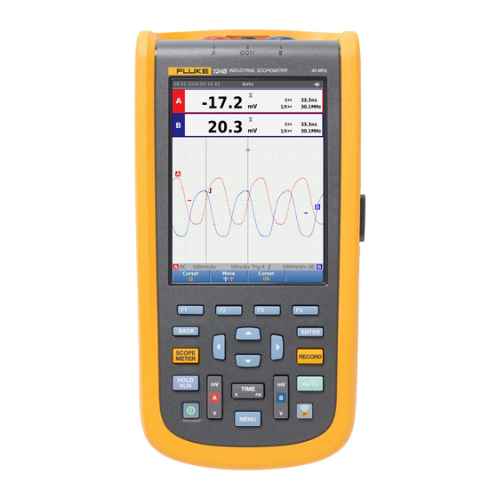
Page 24: How To Read The Screen
123B/124B/125B Users Manual How to Read the Screen The screen is divided into these areas: Information, Reading, Waveform, Status, and Menu. See Table 3. Table 3. Parts of the Screen Item Area Description Date, time, and indicators like Auto range, …
-
Page 25: Connect-And-View
Industrial ScopeMeter® Scope and Meter Mode When you change a setup, a part of the screen shows the choices. Use WXYZ to access the menu choices. Connect-and-View™ The Connect-and-View™ function (Auto Set) enables hands-off operation to display complex unknown signals. This function optimizes the position, range, time base, and triggering to ensure a stable display on most waveforms.
-
Page 26
123B/124B/125B Users Manual BB120 10 mV/A — 1 mV/A see Figure 8 item 5 see Figure 8 item 4 hxv03.eps Figure 7. Measurement Setup… -
Page 27
Industrial ScopeMeter® Scope and Meter Mode hxv04.eps Figure 8. Correct Grounding Setup… -
Page 28
123B/124B/125B Users Manual 10 mV/A — 1 mV/A hxv57.eps Figure 9. Temperature and Current Measurement Setup… -
Page 29: Inputs
Industrial ScopeMeter® Scope and Meter Mode Inputs IntellaSet™ / AutoReading The AutoReading function uses Fluke IntellaSet™ Voltage Measurements technology to enable hands-off operation to display meter For proper grounding, connect the short ground leads to readings that correspond with the shape of the waveform.
-
Page 30: Measurement Type
123B/124B/125B Users Manual Measurement Type To manually set up or change the measurement type: Push to open the Scope and Meter button bar. Push 1 to open the MEASURE menu for Input A. Push 4 to open the MEASURE menu for Input B.
-
Page 31: Screen Freeze
Industrial ScopeMeter® Scope and Meter Mode Screen Freeze You can freeze the screen (all readings and waveforms) at any time: Push to freeze the screen. The information area at the top of the screen shows . Push again to resume measurements. How to Hold a Stable Reading ®…
-
Page 32: Relative Measurements
123B/124B/125B Users Manual Relative Measurements Zero Reference shows the present measurement result with respect to the defined value. Use this feature to monitor the measured value in relation to a known good value. To setup: Push to open the Scope and Meter button bar.
-
Page 33: Auto Range/Manual Range
Industrial ScopeMeter® Scope and Meter Mode Auto Range/Manual Range Time Base Push to toggle between the Manual and Auto The available time base settings are 10 ns/div or Ranging modes. 20 ns/div (depends on model) to 5 s/div in normal mode. When Auto Range is active, the Information area shows Push …
-
Page 34: Noise Reduction
123B/124B/125B Users Manual Glitch Display Noise Reduction By default, the displayed waveform shows glitches. For To view the waveform without higher frequency noise: each time position the minimum and maximum values Push to open the Scope and Meter button bar.
-
Page 35: Waveform Smoothing
Industrial ScopeMeter® Scope and Meter Mode Waveform Smoothing Push 4 to exit the menu. To smooth the waveform: Waveform smoothing suppresses noise without loss of bandwidth. Waveform samples with and without Push to open the Scope and Meter button bar. smoothing are shown in Figure 11.
-
Page 36: Reading Smoothing
123B/124B/125B Users Manual Reading Smoothing Push to make the change. To smooth the readings on A: Push 4 to exit the menu. Push to open the Scope and Meter button bar. The screen shows the resultant envelope waveform. You can use Envelope to observe the variations in time or Push 3 to open the INPUT SETTINGS menu.
-
Page 37: Waveform Acquisition
Industrial ScopeMeter® Scope and Meter Mode Waveform Acquisition The Test Tool can be setup to acquire waveforms as needed for a specific application. This section explains the setup options. Single Acquisition To catch single events, you can perform a single shot (one time screen update).
-
Page 38: Slow Signals
123B/124B/125B Users Manual Slow Signals The roll mode function supplies a visual log of waveform activity. Use slow signals to measure lower frequency waveforms. Push to open the Scope and Meter button bar. Push 2 to open the SCOPE SETTINGS menu.
-
Page 39: Ac Coupling
Industrial ScopeMeter® Scope and Meter Mode AC Coupling Waveform Trigger Use AC-coupling to observe a small ac signal that rides The trigger tells the Test Tool when to start the waveform on a dc signal. trace. You can: • select which input signal to use To select ac-coupling on input A: •…
-
Page 40: Select Trigger Parameters
123B/124B/125B Users Manual Use YZ to adjust the Trigger level continuously. Select Trigger Parameters Observe that the trigger icon on the third time To trigger on the Input A waveform and configure the auto division line indicates the trigger level.
-
Page 41
Industrial ScopeMeter® Scope and Meter Mode Push to highlight A in the Trigger Input group. Push to close all menus. Note to highlight the Update as On trig. Setting the automatic triggering to >1 Hz will Push to make the change. slow down the auto range. -
Page 42: Cursor Measurements
123B/124B/125B Users Manual The readout shows the voltage difference between the Cursor Measurements two cursors and the voltages at the cursors in relation to Cursors allow you to make precise digital measurements the zero icon (-). on waveforms. Cursors are disabled for 3-phase power measurements.
-
Page 43: Vertical Cursors
Industrial ScopeMeter® Scope and Meter Mode Vertical Cursors Use vertical cursors to measure the time difference “t” between the cursors and the voltage difference between the two markers. To use the cursors for a time measurement: Push 3 to select CURSOR ON. Push 1 to select .
-
Page 44: Rise Time Measurements
123B/124B/125B Users Manual Rise Time Measurements To measure rise time: Push 3 to select CURSOR ON. Push 1 to select (rise time). Observe that two horizontal cursors are displayed. Push 4 if only one trace is displayed and select MANUAL or AUTO.
-
Page 45: High Frequency Measurements With 10:1 Probe
Power and Harmonics Mode High Frequency Measurements with 10:1 Probe Probe Adjustment Fluke recommends the VP41 10:1 Probe to measure high The VP41 Probe is always adapted correctly to its inputs. frequency signals in circuits with high impedance. The High frequency adjustment is not necessary.
-
Page 46: Volts/Amps/Watt Measurements
123B/124B/125B Users Manual To select the power and harmonics mode: to highlight SELECT… in Probe A group. Push to open the SETTINGS menu. Push to open the Probe A menu. to highlight POWER HARMONICS. to highlight the Probe A type.
-
Page 47: Volt/Amp Readings
Industrial ScopeMeter® Power and Harmonics Mode Table 4 is a list of the visible readings when Table 5 is a list of the visible readings when Power is Voltage/Current is selected. selected. Table 5. Watt Readings Table 4. Volt/Amp Readings hxv28.eps hxv27.eps Symbol…
-
Page 48: Harmonics Measurements
123B/124B/125B Users Manual In the Harmonics mode the Test Tool always uses the Harmonics Measurements AUTO mode. The vertical sensitivity range and the time Harmonics are periodic distortions of voltage, current, or base range are automatically adjusted to the most power sine waves.
-
Page 49: Harmonics Voltage Measurements
Industrial ScopeMeter® Power and Harmonics Mode Table 6. Harmonics Voltage Measurements Readout Description rms V AC Voltage AC value on channel A THD is the amount of harmonics in a signal as a percentage of the total RMS value (THD%r) or as a percentage of the fundamental (THD%f).
-
Page 50: Harmonics Current Measurements
123B/124B/125B Users Manual Table 7. Harmonics Current Measurements Readout Description Rms AAc Current AC value on channel A THD is the amount of harmonics in a signal as a percentage of the total RMS value (THD%r) or as a percentage of the fundamental (THD%f).
-
Page 51: Harmonics Power Measurements
Industrial ScopeMeter® Power and Harmonics Mode Table 8. Harmonics Power Measurements Readout Description Active power in Watts K-Factor indicates the losses in transformers due to harmonic currents. The harmonics component as selected with the cursor. Use WX to move the cursor. In the example screen this is the third Nr (3) harmonic.
-
Page 52: Zooming Harmonics
123B/124B/125B Users Manual Zooming Harmonics For extended information on Fieldbuses and fieldbus measurement, see Appendix A of this manual. If the harmonics bars screen is shown, you can zoom vertically for a more detailed view. Use to zoom in Note or zoom out.
-
Page 53: Bus Measurement Inputs
Industrial ScopeMeter® Fieldbus Mode Table 9. Bus Measurement Inputs Input Advised Subtype Probe AS-i STL120 STL120 Interbus S RS-422 VP41 DeviceNet STL120 RS-232 STL120 Modbus RS-485 STL120 Foundation STL120 fieldbus DP/RS-485 STL120 Profibus hxv32.eps PA/31.25 kBit/s STL120 Use the BB120 Banana-to-BNC Adapter to connect a BNC cable for bus measurements.
-
Page 54: How To Read The Screen
123B/124B/125B Users Manual How to Read the Screen The bus test screen shows the status of the various signal properties. To open, go the main screen and push 3. Information is represented in four columns, see Table 10. Table 10. Field Bus Test Screen…
-
Page 55: Test Signal Properties
Industrial ScopeMeter® Fieldbus Mode Table 11. Test Signal Properties Property Explanation Property Explanation VBias Bias voltage CAN-Rec. L CAN-recessive low level voltage CAN-recessive high to low level CAN-Rec. H-L V High High level voltage voltage CAN-Rec. H CAN-recessive high level voltage Vpk-pk Peak to peak voltage V-Level High-Bias…
-
Page 56: Bus Test Screen Indicators
123B/124B/125B Users Manual Table 12. Bus Test Screen Indicators Indicator Description Bus activity indicators Bus activity indicator 1: (filled) voltage measured (open) no voltage measured Bus activity indicators 2 and 3: (both open) no activity …
-
Page 57: How To View The Bus Waveform Screen
Industrial ScopeMeter® Fieldbus Mode Figure 12 shows the bus health indicator boundaries. The high level voltage of a bus must be between +3.0 V (MIN) and +15.0 V (MAX). Depending on the measurement result, the displayed indicator will be: Result is between 4.2 and 13.8V. (10 % of 12 V = 1.2 V) Result is between 3 V and 4.2 V, or between 13.8 V and 15 V.
-
Page 58: Test Limits
123B/124B/125B Users Manual Test Limits The test limits apply to the selected bus type. To change the test limits: Push to open the MENU. to highlight BUSHEALTH. Push to open the BUS HEALTH menu. to highlight the bus type.
-
Page 59: Recorder Mode
Industrial ScopeMeter® Recorder Mode Edit the limit. Push 3 to select N/A if a limit should not be involved in the test. 10. Push 4 to accept the limits and return to the test screen. In the test screen the text LIMIT will be followed by an * if any of the limits is not the default limit.
-
Page 60: Start And Stop Meter Recording
123B/124B/125B Users Manual The Meter Recorder makes the Test Tool act as a paperless recorder that collects a series of parameter measurements over time and shows the result as a graph or a trend-line on screen. This is most useful to…
-
Page 61
Industrial ScopeMeter® Recorder Mode YZWX and to enter the time in hours and minutes. Events are used to determine how often the measured reading deviates from the initial reading when recording starts. It is easy to see the time of a deviation when you view the recording after it stops. -
Page 62: Cursor Measurements
123B/124B/125B Users Manual Cursor Measurements Use the cursor to make precise digital measurements on the plotted graphs. The display shows the measurement results, the date, and the time at the cursor position. Each result is a maximum and a minimum measurement.
-
Page 63: Zoom In/Out On Logged Meter Data
Industrial ScopeMeter® Recorder Mode Zoom In/Out on Logged Meter Data Scope Record Mode By default, the display shows a compressed view of all The Scope Record mode shows all the waveform data as the data with minimum and maximum pairs for the interval a long waveform of each active input.
-
Page 64
123B/124B/125B Users Manual 13. To start or stop a recording, push or 4. The Test Tool continuously logs all data to memory. While recording, the display does not update since all the processing capacity is needed for recording. Note The Test Tool beeps when an event occurs. -
Page 65: Save And Recall Data Sets
Industrial ScopeMeter® Save and Recall Data Sets Save and Recall Data Sets To change the name of the data set: The Test Tool has 20 internal data memory locations. In XWYZ and 1 to select the characters for each memory location you can save a data set in Scope the name.
-
Page 66: Test Sequence
123B/124B/125B Users Manual If no free memory locations are available, a message pops up for you to overwrite the oldest data set. To continue: Push 3 to cancel the overwrite to the oldest data set. You must delete one or more memory locations and then save again.
-
Page 67: Setting Recall
Industrial ScopeMeter® Save and Recall Data Sets Setting Recall Data Set Management To recall a setting: You can copy, move, rename, and delete a data set. Push to open the menu. To manage the data set: Push 3 to open the RECALL MEMORY menu. Push …
-
Page 68: Waveform Comparison
123B/124B/125B Users Manual Waveform Comparison Use Recall to easily compare the A and B waveforms with previously measured waveforms. You can compare a waveform of one phase with a waveform of another phase or compare with a previously measured waveform on the same test point.
-
Page 69: Communication
• PC or laptop that uses FlukeView ScopeMeter software with an optical cable or wireless interface • Tablet or smartphone using Fluke Connect with WiFi interface Optical Interface Connect the Test Tool to a computer with a wired ® ®…
-
Page 70
123B/124B/125B Users Manual W Caution The menu shows: Do not use the USB port to directly • WiFi name. The SSID is used to detect the Test Tool communicate with an external device. WiFi. To set up the Test Tool for use with a wireless •… -
Page 71: Maintenance
Hazardous with water and get medical aid. voltage exposure is possible. • Use only the Fluke BP290 as a • Remove the input signals before you replacement battery. clean the Product.
-
Page 72: 10:1 Scope Probes
123B/124B/125B Users Manual • 10:1 Scope Probes Do not disassemble or crush battery cells and battery packs. The 10:1 voltage probe (VP41) that is supplied with the Test Tool (varies by model) is always adjusted correctly • Do not keep cells or batteries in a and needs no further adjustment.
-
Page 73: Calibration Information
Calibration Information The Test Tool specifications are based on a 1 year calibration cycle. Recalibration must be done by qualified personnel. Contact your local Fluke representative for more information about recalibration. To find the firmware version and calibration date of your Test Tool: Push …
-
Page 74
123B/124B/125B Users Manual Push to open the INFORMATION menu. The User Information menu screen has information about the model number with firmware version, the serial number, the calibration number with latest calibration date, installed (firmware) options, and memory usage information. -
Page 75: Replaceable Parts And Accessories
Industrial ScopeMeter® Replaceable Parts and Accessories Table 13. Replaceable Parts and Accessories Item (see Figure 1) Description Order Code Fluke Test Tool Rechargeable Li-ion Battery Pack BP290 Switch Mode Power Supply, Adapter/Battery Charger BC430/820 Set of two Shielded Test Leads (Red and Blue), designed for use only with ®…
-
Page 76: Optional Accessories
Bushealth Test Adapter: connects the probe tip to busses that use a not shown BHT190 DB9, RJ-45, or a M12 connector Software & Cable Carrying Case Kit (Supplied with Fluke 12x/S) SCC 120B Set contains the following parts: • Screen Protector …
-
Page 77: Tips
Industrial ScopeMeter® Tips Tips Power Off Timer By default, the power off timer is set to 30 minutes after the This section is information and tips on how to best use last key press. To change the time to 5 minutes or turn off: the Test Tool.
-
Page 78: Autoset Options
123B/124B/125B Users Manual Autoset Options Grounding Guidelines On delivery or after a reset, the Autoset function captures XW Warning waveforms ≥15 Hz and sets the input coupling to DC. To prevent possible electrical shock, fire, or Note personal injury, use only one COM (common) ˜…
-
Page 79: Specifications
STL120-IV 1:1 shielded test leads … DC to 12.5 MHz (-3 dB) / DC to 20 MHz (-6 dB) with VP41 10:1 probe 125B, 124B ……….DC to 40 MHz (-3 dB) 123B (optional accessory) ……DC to 20 MHz (-3 dB) AC Coupled (LF roll off): without probes and test leads ……<10 Hz (-3 dB) with STL120-IV ……….
-
Page 80
Normal: Equivalent sampling 125B, 124B ……….10 ns to 500 ns/div 123B…………20 ns to 500 ns/div Real time sampling ……… 1 μs to 5 s/div Single (real time) ……….1 μs to 5 s/div Roll (real time) ……….1s to 60 s/div Sampling Rate (for both channels simultaneously) Equivalent sampling (repetitive signals) …. -
Page 81: Dual Input Meter
Sensitivity A and B @ DC to 5 MHz ……….. 0.5 divisions or 5 mV @ 40 MHz 125B, 124B …………. 1.5 divisions 123B …………..4 divisions @ 60 MHz 125B, 124B …………. 4 divisions 123B …………..NA Slope …………… Positive, Negative…
-
Page 82
123B/124B/125B Users Manual Input A and Input B DC Voltage (VDC) Ranges …………..500 mV, 5 V, 50 V, 500 V, 750 V Accuracy …………. ±(0.5 % + 5 counts) Normal Mode Rejection (SMR) ……>60 dB @ 50 or 60 Hz ±0.1 % Common Mode Rejection (CMRR) ….. -
Page 83
125B, 124B …………. 1 Hz, 10 Hz, 100 Hz, 1 kHz, 10 kHz, 100 kHz,1 MHz, 10 MHz, and 70 MHz 123B …………..1 Hz, 10 Hz, 100 Hz, 1 kHz, 10 kHz, 100 kHz,1 MHz, 10 MHz, and 50 MHz… -
Page 84
123B/124B/125B Users Manual Accuracy 125B, 124B @ 1 Hz to 1 MHz ……..±(0.5 % + 2 counts) @ 1 to 10 MHz ……….±(1.0 % + 2 counts) @ 10 to 70 MHz ………. ±(2.5 % + 2 counts) 123B @ 1 Hz to 1 MHz …….. -
Page 85
Industrial ScopeMeter® Specifications Amperes (AMP) with current clamp Ranges …………same as VDC, VAC, VAC+DC, or PEAK Scale Factors ……….0.1 mV/A, 1 mV/A, 10 mV/A, 100 mV/A, 400 mV/A, 1 V/A, 10 mV/mA Accuracy …………same as VDC, VAC, VAC+DC, or PEAK (add current clamp uncertainty) with iFlex clamp Ranges ………… -
Page 86
123B/124B/125B Users Manual Phase Modes …………..A to B, B to A Range …………..0 to 359 degrees Accuracy <1 MHz …………2 degrees 1 MHz to 5 MHz ……….5 degrees Resolution …………1 degree Power (125B) Configurations …………. 1 phase / 3 phase 3 conductor balanced loads (3 phase: fundamental component only, AUTOSET mode only) Power Factor (PF) ………. -
Page 87
Ranges 125B …………..50 Ω, 500 Ω, 5 kΩ, 50 kΩ, 500 kΩ, 5 MΩ, 30 MΩ 124B, 123B …………. 500 Ω, 5 kΩ, 50 kΩ, 500 kΩ, 5 MΩ, 30 MΩ Accuracy………….. ±(0.6 % + 5 counts) 50 Ω ±(2 % + 20 counts) Full Scale Reading: 50 Ω… -
Page 88: Cursor Readout (124B, 125B)
123B/124B/125B Users Manual Full Scale Reading ……….5000 counts Measurement Current ……… 500 nA to 0.5 mA, increases with increasing ranges Advanced Meter Functions Zero Set Set actual value to reference Fast/Normal/Smooth Meter settling time Fast: 1 s @ 1 μs to 10 ms/div.
-
Page 89: Recorder
Industrial ScopeMeter® Specifications Rise or Fall Time Transition Time, 0 %-Level and 100 %-Level Readout (Manual or Auto Leveling; Auto Leveling only possible in Single Channel Mode) Accuracy As Oscilloscope Accuracy Recorder The recorder captures meter readings in Meter Recorder mode or continuously captures waveform samples in Scope Recorder mode. The information is stored on internal memory or on optional SD card with the 125B or 124B.
-
Page 90: Power Quality (125B)
123B/124B/125B Users Manual Power Quality (125B) Readings …………..Watt, VA, VAR, PF, DPF, Hz Watt, VA, var ranges (auto) ……..250 W to 250 MW, 625 MW, 1.56 GW when selected: total (%r) ……..±(2 % + 6 counts) when selected: fundamental (%f) ……±(4 % + 4 counts) DPF ……………..
-
Page 91: Field Bus Measurements (125B)
Industrial ScopeMeter® Specifications Field Bus Measurements (125B) Type Subtype Protocol AS-i NEN-EN50295 ISO-11898 Interbus S RS-422 EIA-422 RS-232 RS-232/EIA-232 Modbus RS-485 RS-485/EIA-485 Foundation Fieldbus 61158 type 1, 31.25 kBit EIA-485 Profibus 61158 type 1 RS-232 EIA-232 RS-485 EIA-485…
-
Page 92: Miscellaneous
123B/124B/125B Users Manual Miscellaneous Display Type …………..5.7-inch color active matrix TFT Resolution …………640 x 480 pixels Waveform Display Vertical …………10 div of 40 pixels Horizontal …………12 div of 40 pixels Power External …………… via Power Adapter BC430/820 Input Voltage ………..
-
Page 93: Environmental
Industrial ScopeMeter® Specifications Interface Optically isolated USB to PC/laptop ….Transfer screen dumps (bitmaps), settings and data using OC4USB optically isolated ® ® ® USB adapter/cable, (optional), using FlukeView ScopeMeter software for Windows Optional WiFi Adapter ……… Fast transfer of screen dumps (bitmaps), settings and data to PC/laptop, tablet, smartphone, etc.
-
Page 94
123B/124B/125B Users Manual Vibration …………..MIL-PRF-28800F, Class 2 Shock …………..30 g maximum Electromagnetic Compatibility (EMC) International …………IEC 61326-1: Industrial CISPR 11: Group 1, Class A Group 1: Equipment has intentionally generated and/or uses conductively-coupled radio frequency energy that is necessary for the internal function of the equipment itself. -
Page 95
Industrial ScopeMeter® Specifications Safety General…………..IEC 61010-1: Pollution Degree 2 Measurement …………IEC 61010-2-033: CAT IV 600 V / CAT III 750 V Max. Input Voltage Input A and B Direct on input or with leads ……. 600 Vrms CAT IV for derating, see Figure 15. With Banana-to BNC Adapter BB120 …. -
Page 96
123B/124B/125B Users Manual The Fluke 12xB series, including standard accessories, conforms to the EEC directive 2004/108/EC for EMC immunity, as defined by EN61326-1: 2006, with the addition of the table below. Trace disturbance with STL120-IV No visible Disturbance less than…
This manual is also suitable for:
124b125b
Изображения служат только для ознакомления,
см. техническую документацию
6 000 руб.
× 1 =
6 000 руб.
Добавить в корзину 1 шт.
на сумму 191 200 руб.
Номенклатурный номер: 9000318179
Артикул: Fluke 123B/EU
PartNumber: 4755659
Бренд / Производитель: Fluke

Описание
Упрощенная процедура тестирования, более достоверный и быстрый поиск и устранение неисправностей электромеханического оборудования
Компактный осциллограф-мультиметр ScopeMeter® серии 120 — это прочное устройство для поиска неисправностей и проведения технического обслуживания электрического и электромеханического оборудования. Это поистине универсальный испытательный инструмент, объединяющий осциллограф, мультиметр и высокоскоростной регистратор в одном удобном приборе. Программное обеспечение осциллографа-мультиметра серии 120B Series также включает в себя мобильное приложение Fluke Connect® и FlukeView® для обеспечения дальнейшего сотрудничества, анализа данных и архивирования критически важной диагностической информации.
· Совместимы с FLUKE CONNECT: Просматривайте данные непосредственно на приборе или с помощью мобильного приложения Fluke Connect ( Функция пуска Fluke Connect and View™ автоматически отображает формы сигналов без необходимости настройки амплитуды, задания временных параметров развертки и запуска, а с технологией Intellaset™ выполняется анализ сигнала и автоматическое отображение важных цифровых показаний. Все это существенно ускоряет поиск и устранение неисправностей, как никогда ранее );
· Цифровой осциллограф и мультиметр с двумя входами;
· Полоса пропускания осциллографа 40 или 20 МГц;
· Два цифровых мультиметра на 5 000 отсчетов, измеряющих истинные среднеквадратичные значения;
· Удобная функция автоматического пуска Connect-and-View™ для работы со свободными руками;
· Технология IntellaSet™ автоматически, интеллектуально подстраивает численное показание в соответствии с измеренным сигналом;
· Регистратор форм сигналов и показаний измерителя с двумя входами для отслеживания тенденций изменения данных на протяжении длительных периодов;
· Функция регистрации обнаруженных событий фиксирует непериодические перемежающиеся сигналы повторяющейся формы с частотой до 4 кГц;
· Экранированные измерительные провода для осциллографа, а также для измерения сопротивления и проверки целостности цепи;
· Измерения сопротивления, емкости, проверка диодов и целостности цепи;
· Измерения мощности (Вт, ВА, ВАр, коэффициент мощности, коэффициент реактивной мощности, Гц);
· Гармоники напряжения, тока и мощности;
· Проверка промышленных сетей с функцией тестирования физического уровня BusHealth на соответствие определенным в рекомендациях номинальным уровням;
· Сохранение или извлечение из памяти данных и установок прибора;
· Сохранение настроек прибора, заданных последовательностью проверок текущего технического обслуживания или наиболее часто используемых процедур проверок;
· Внешний USB-интерфейс с оптической развязкой для передачи, архивирования и анализа данных осциллографа или измерителя;
· Дополнительный WiFi-адаптер, подключенный к внутреннему USB-порту для беспроводной передачи данных на ПК, блокнотный ПК или в мобильное приложение Fluke Connect®;
· Программное обеспечение FlukeView® ScopeMeter® для Windows®;
· Прочная конструкция, выдерживающая вибрацию 3g, удар 30g и со степенью защиты IP51 в соответствии с EN/IEC60529;
· Самая высокая категория безопасности в промышленности: категория безопасности CAT IV 600 В;
· Литиево-ионная батарея, семь часов работы (с временем заряда четыре часа).
Комплектация:
Промышленный портативный осциллограф Fluke 123B 1
Экранированные измерительные провода с черными заземляющими проводами 2
Черный измерительный провод (для заземления) 1
Зажимы типа «крючок» (красный, синий) 2
Адаптеры для соединения разъемов типа «банан» с BNC-разъемами (черные) 1
Угловой переходник USB 1
WiFi USB-адаптер* 1
Источник питания с переключаемыми режимами, адаптер / зарядное устройство 1
Аккумуляторный источник питания (литий-ионный) 1
*В комплект поставки приборов Fluke 123B/S также входят мягкий
футляр для переноски, ПО FlukeView ™ для Windows, магнитная подвеска и защитная пленка для экрана.
** Адаптер WiFi USB доступен НЕ во всех странах. Узнайте
у местного представителя компании Fluke.
Технические параметры
| Количество каналов | 2 | |
| Полоса пропускания, МГц | 20 | |
| Госреестр РФ | да | |
| Тип | цифровой | |
| Серия | scopemeter 120 | |
| Вес, кг | 2.75 | |
Техническая документация
25 000 руб.

66 320 руб.
Главная
—
—
—Осциллограф Fluke 123B/INT
Артикул:
4755710
Гарантия:
6 месяцев
Под заказ
Наши менеджеры обязательно свяжутся с вами и уточнят условия заказа
- Описание
- Характеристики
- Отзывы
- Задать вопрос
- Комплектация
Описание
Осциллограф Fluke 123B/INT
Для осуществления измерений и наблюдений за параметрами электрических сигналов предлагаем купить Осциллограф Fluke 123B/INT, представленные в каталоге нашего интернет-магазина Флюк. Модель 123B/INT серии Fluke Industrial отличается практичностью и удобством в использовании. В нашем интернет-магазине приемлемая стоимость прибора — 99396 руб. Предоставляется возможность оплаты наличными средствами и по безналичному расчету.
FLUKE 123B/INT Портативный осциллограф Scopemeter 120B Series, 2 Аналоговых, 20 МГц, 400 Квыборок/с, 512 точек, 17.5 нс
Линия продукции Scopemeter 120B серии
2 Аналоговых канала
Полоса пропускания 20МГц
Частота выборки 400Квыборок/с
Глубина памяти дисплея 512 точек
Расчитанное время нарастания 17.5нс
5,7 дюймовый цветной дисплей с активной матрицей TFT (640 x 480 пикселов)
Тип Штекера — универсальная вилка
SVHC (Особо Опасные Вещества) To Be Advised
Получить больше информации, ответов на интересующие вас вопросы, подробнее узнать об особенности модели и купить Осциллограф Fluke 123B/INT по выгодной цене вы можете в нашем розничном зале или интернет магазине Fluke-online.ru
Документы
Характеристики
| Fluke 123B/INT | |
|---|---|
| Макс. скорость развертки | 17.5 нс/деление |
| Макс. частота взятия отсчетов в реальном времени | 40 Мвыб/с + эквивалентная выборка во времени |
| Ширина полосы частот | 20МГц |
| Количество каналов | 2 |
Комплектация
- Осциллограф 123B/INT
- Адаптер
- Переходник Banana — BNC
- Упаковка батареи
- 2 экранированных испытательных провода с заземлением
- 2 зажима типа крюк
Задать вопрос
Вы можете задать любой интересующий вас вопрос по товару или работе магазина.
Наши квалифицированные специалисты обязательно вам помогут.
|
Возникли вопросы? Здравствуйте! Меня зовут Дмитрий Кузнецов. Я руководитель отдела «КИПиА». Готов ответить на все ваши вопросы по товару «Осциллограф Fluke 123B/INT». Напишите или позвоните мне, если вам нужна консультация или вы хотите оформить заказ. |
Оставить отзыв
У данного товара нет отзывов. Станьте первым, кто оставил отзыв об этом товаре!
| Режим осциллографа | ||
| Вертикально | ||
| Частотная характеристика — подключение по постоянному току | Без датчиков и измерительных проводов (с адаптером BB120) |
123B: по постоянному току и до 20 МГц (–3 дБ) 124B и 125B: по постоянному току и до 40 МГц (–3 дБ) |
| С экранированными измерительными проводами STL120-IV 1:1 | По постоянному току и до 12,5 МГц (–3 дБ) / по постоянному току и до 20 МГц (–6 дБ) | |
| С датчиком VP41 10:1: |
123B: по постоянному току и до 20 МГц (–3 дБ) 124B и 125B: по постоянному току и до 40 МГц (–3 дБ) |
|
| Частотная характеристика — подключение по переменному току (спад по нижним частотам) | Без датчиков и измерительных проводов | < 10 Гц (–3 дБ) |
| С экранированными измерительными проводами STL120-IV 1:1 | < 10 Гц (–3 дБ) | |
| С датчиком VP41 10:1: | < 10 Гц (–3 дБ) | |
|
Время нарастания, без датчиков, измерительных проводов |
123B < 17,5 нс |
|
| Входной импеданс | Без датчиков и измерительных проводов | 1 МОм//20 пФ |
| С BB120 | 1 МОм//24 пФ | |
| С экранированными измерительными проводами STL120-IV 1:1 | 1 МОм//230 пФ | |
| С датчиком VP41 10:1: | 5 МОм//15,5 пФ | |
| Чувствительность |
от 5 мВ до 200 В/деление |
|
| Аналоговый ограничитель полосы пропускания |
10 кГц |
|
| Режимы отображения |
A, -A, B, -B |
|
| Макс. напряжение на входах A и B | Постоянное, с измерительными проводами или с датчиком VP41 | 600 В (среднеквадратичное значение) кат. IV, макс. напряжение 750 В (среднеквадратичное значение). |
| С BB120 | 600 В (среднеквадратичное) | |
| Макс. плавающее напряжение, между любой клеммой и заземлением |
600 В (среднеквадратичное значение) кат. IV, 750 В (среднеквадратичное значение) до 400 Гц |
|
| Горизонтально | ||
| Режимы работы осциллографа |
Нормальный, одиночный, развертка |
|
| Диапазоны (норм.) | Эквивалентная выборка | 123B: от 20 до 500 нс/деление, |
| 124B и 125B: от 10 до 500 нс/деление | ||
| Выборка в реальном времени | от 1 мкс до 5 с/деление | |
| Одиночный (в реальном времени) | от 1 мкс до 5 с/деление | |
| Развертка (в реальном времени) | от 1 с до 60 с/деление | |
| Частота дискретизации (одновременно для обоих каналов) | Равномерная дискретизация (повторяющиеся сигналы) | До 4 Гвыб/с |
| Дискретизация в реальном масштабе времени от 1 мкс до 60 с/деление | 40 Мвыб/с | |
| Пуск | ||
| Режим обновления экрана |
В режиме автоколебаний, в режиме синхронизации |
|
| Источник |
A, B |
|
| Чувствительность A и B | постоянный ток и до 5 МГц | 0,5 деления или 5 мВ |
| при 40 МГц | 123B: 4 деления | |
| 124B и 125B: 1,5 деления | ||
| при 60 МГц | 123B: N/A | |
| 124B и 125B: 4 деления | ||
| Фронт |
Положительный, отрицательный |
|
| Расширенные функции осциллографа | ||
| Режимы отображения | Нормальный | Обнаружение выбросов от 25 нс; отображение непрерывной осциллограммы аналогового типа. |
| Сглаживание | Подавление отображения шумов сигнала. | |
| Всплески выкл. | Не регистрирует выбросы между отсчетами | |
| Огибающая | Регистрация и отображение минимального и максимального показаний за период времени. | |
| Автоматическая настройка (Connect-and-View™) |
Непрерывная полностью автоматизированная регулировка масштаба по осям напряжения и времени, уровней запуска развертки, мертвой зоны запуска и выхода из синхронизации. Возможность ручной настройки амплитуды, скорости развертки или уровня запуска. |
| Измерительный прибор с двумя входами |
| Указанные ниже значения погрешностей (проценты от показания + число единиц счета) действительны от 18 до 28 °C. |
| На каждый °C ниже 18 °C или выше 28 °C следует прибавить 0,1 x (указанное значение погрешности). При измерении напряжения датчиком 10:1 следует прибавить погрешность датчика +1 %. На экране должно отображаться больше одного периода сигнала. |
| Вход A и вход B | ||
| Напряжение постоянного тока (VDC) | ||
| Диапазоны |
500 мВ, 5 В, 50 В, 500 В, 750 В |
|
| Погрешность |
± (0,5 % + 5 единиц счета) |
|
| Подавление синфазной помехи (CMRR) |
> 100 дБ при постоянном токе, > 60 дБ при 50, 60 или 400 Гц |
|
| Отсчеты во всем диапазоне |
5 000 отсчетов |
|
| Истинные среднеквадратичные значения напряжения (В переменного и В переменного + постоянного тока) | ||
| Диапазоны |
500 мВ, 5 В, 50 В, 500 В, 750 В |
|
| Погрешность в пределах от 5 до 100 % диапазона (подключение по постоянному току) | от постоянного тока до 60 Гц (В переменного + постоянного тока) | ± (1 % + 10 единиц счета) |
| от 1 до 60 Гц (В переменного тока) | ± (1 % + 10 единиц счета) | |
| Погрешность в пределах от 5 до 100 % диапазона (подключение по переменному или по постоянному току) | от 60 Гц до 20 кГц | ± (2,5 %+15 единиц счета) |
| Подавление постоянной составляющей (только для напряжения переменного тока) |
> 50 дБ |
|
| Подавление синфазной помехи (CMRR) | > 100 дБ для постоянного тока | |
| > 60 дБ при 50, 60 или 400 Гц | ||
| Отсчеты во всем диапазоне |
5 000 отсчетов, показание прибора не зависит от коэффициента амплитуды сигнала. |
|
| Пик | ||
| Режимы |
Максимальное пиковое значение, минимальное пиковое значение или размах |
|
| Диапазоны |
500 мВ, 5 В, 50 В, 500 В, 2 200 В |
|
| Погрешность | Погрешность Максимальное или минимальное пиковое значение | 5 % от диапазона |
| Погрешность, размах сигнала | 10 % от диапазона | |
| Отсчеты во всем диапазоне |
500 отсчетов |
|
| Частота (Гц) | ||
| Диапазоны | 123B: 1 Гц, 10 Гц, 100 Гц, 1 кГц, 10 кГц, 100 кГц, 1 МГц, 10 МГц, 50 МГц | |
| 124B и 125B: 1 Гц, 10 Гц, 100 Гц, 1 кГц, 10 кГц, 100 кГц, 1 МГц, 10 МГц, 70 МГц | ||
| Диапазон частот |
от 15 Гц (1 Гц) до 50 МГц при непрерывной автоматической подстройке |
|
| Погрешность в диапазоне от 1 Гц до 1 МГц |
± (0,5 % + 2 единицы счета) |
|
| Отсчеты во всем диапазоне |
Максимальное показание дисплея 10 000 |
|
| Число оборотов в минуту | ||
| Максимальное показание |
50,00 тыс. об./мин. |
|
| Погрешность |
± (0,5 % + 2 единицы счета) |
|
| Рабочий цикл (ИМПУЛЬС) | ||
| Диапазон |
от 2 до 98 % |
|
| Диапазон частот |
от 15 Гц (1 Гц) до 30 МГц при непрерывной автоматической настройке |
|
| Длительность импульса (PULSE) | ||
| Диапазон частот |
от 15 Гц (1 Гц) до 30 МГц при непрерывной автоматической настройке |
|
| Отсчеты во всем диапазоне |
1 000 отсчетов |
|
| Сила тока (AMP) | ||
| С токовыми клещами | Диапазоны | Как при измерении напряжения пост. тока, напряжения перем. тока, напряжения пост. и перем. тока или пикового значения |
| Коэффициенты усиления | 0,1 мВ/A, 1 мВ/A, 10 мВ/A, 100 мВ/A, 400 мВ/A, 1 В/A, 10 мВ/мА | |
| Погрешность | Как при измерении напряжения пост. тока, напряжения перем. тока, напряжения пост. и перем. тока или пикового значения (добавление погрешности измерения тока) | |
| Температура (TEMP) с дополнительным датчиком температуры | ||
| Диапазон |
200 °C/деление (200 °F/деление) |
|
| Коэффициент усиления |
1 мВ/°C и 1 мВ/°F |
|
| Погрешность |
Как при измерении напряжения пост. тока (добавление погрешности измерения температуры) |
|
| Децибелы (дБ) | ||
| 0 дБВ |
1 В |
|
| 0 дБм (600 Ом / 50 Ом) |
1 мВт соответствует 600 Ом или 50 Ом |
|
| дБ напряжения |
Напряжение постоянного, переменного или переменного + постоянного тока |
|
| Отсчеты во всем диапазоне |
1 000 отсчетов |
|
| Коэффициент амплитуды (CREST) | ||
| Диапазон |
1–10 |
|
| Отсчеты во всем диапазоне |
90 отсчетов |
|
| Фаза | ||
| Режимы |
от A к B, от B к A |
|
| Диапазон |
от 0 до 359 градусов |
|
| Разрешение |
1 градус |
|
| Мощность (только 125B) | ||
| Схемы подключения |
1-фазная / 3-фазная, 3-проводные сбалансированные нагрузки (для 3-фазных систем: только основная гармоника, только в режиме AUTOSET автоматической настройки) |
|
| Коэффициент мощности (PF) |
Отношение активной и полной мощности — от 0,00 до 1,00 |
|
| Ватт | Среднеквадратичное значение произведения отсчетов на входе A (напряжение) и на входе B (сила тока) | |
| Отсчеты во всем диапазоне | 999 отсчетов | |
| ВА | В (среднеквадратичное значение) x А (среднеквадратичное значение) | |
| Отсчеты во всем диапазоне | 999 отсчетов | |
| Реактивная мощность (ВАр) | [S][208]=»2″[S][210]=»2″[S][212] | |
| Отсчеты во всем диапазоне | 999 отсчетов | |
| Напряжение ШИМ | ||
| Назначение |
Измерение параметров широтно-импульсных модулированных сигналов, например выходов обратного преобразователя электродвигательного привода |
|
| Принцип действия |
Показания отображают эффективное напряжение в соответствии со средним значением по выборкам за целое число периодов основной частоты |
|
| Погрешность |
Как при измерении среднеквадратичного значения напряжения для гармонических сигналов |
|
| между входом A и общей шиной | ||
| Ом (Ω) | ||
| Диапазоны | 123B и 124B | 500 Ом, 5 кОм, 50 кОм, 500 кОм, 5 МОм, 30 МОм |
| 125B | 50 Ом, 500 Ом, 5 кОм, 50 кОм, 500 кОм, 5 МОм, 30 МОм | |
| Погрешность |
± (0,6 % + 5 единиц) 50 Ом ± (2 % + 20 единиц) |
|
| Отсчеты во всем диапазоне |
от 50 Ом до 5 МОм — 5 000 отсчетов, 30 МОм — 3 000 отсчетов |
|
| Измерительный ток |
от 0,5 мА до 50 нА, уменьшается с ростом предела измерений |
|
| Напряжение разомкнутой цепи |
< 4 В |
|
| Проверка целостности цепей (Cont) | ||
| Звуковой сигнал |
< (30 Ом ± 5 Ом) в диапазоне 50 Ом |
|
| Измерительный ток |
0,5 мА |
|
| Обнаружение коротких замыканий |
≥ 1 мс |
|
| Диод | ||
| Измерительное напряжение | при 0,5 мА | > 2,8 В |
| при разомкнутой цепи | < 4 В | |
| Измерительный ток |
0,5 мА |
|
| Полярность |
+ на входе A, – на общем проводе COM |
|
| Емкость (CAP) | ||
| Диапазоны |
50 нФ, 500 нФ, 5 мкФ, 50 мкФ, 500 мкФ |
|
| Отсчеты во всем диапазоне |
5 000 отсчетов |
|
| Измерительный ток |
от 500 нА до 0,5 мА, возрастает с ростом предела измерений |
| Дополнительные функции измерений | |
| Установка нуля |
Устанавливает фактическое значение в качестве эталонного |
| Режим AutoHold (на входе А) |
Обнаруживает и фиксирует стабильные результаты измерения. При обнаружении стабильных показаний генерирует звуковой сигнал. Функция AutoHold работает с основным результатом измерения, с пороговыми значениями 1 В (размаха) для сигналов переменного и 100 мВ для сигналов постоянного тока. |
| С фиксированной десятичной точкой |
Активируется при использовании клавиш ослабления. |
| Получение показаний с помощью курсоров (124B и 125B) | |
| Источники |
A, B |
| Одна вертикальная линия |
Получение среднего, минимального и максимального значения |
|
Среднее, минимальное и максимальное значения; время от начала снятия показаний (в режиме ROLL непрерывной развертки, прибор в режиме HOLD) |
|
| Минимальное и максимальное показание, время от начала снятия показаний (в режиме RECORDER записи, прибор в режиме HOLD) | |
| Величины гармоник в режиме POWER QUALITY контроля качества электроэнергии. | |
| Двойные вертикальные линии | Значения размаха сигнала, временного интервала и обратного временного интервала |
| Среднее, минимальное и максимальное значения; значение временного интервала (в режиме ROLL непрерывной развертки, прибор в режиме HOLD) | |
| Двойные горизонтальные линии |
Считывание максимального и минимального значений и размаха сигнала |
| Время нарастания или спада |
Снятие показаний времени изменения, уровней 0 % и 100 % (при ручной или автоматической установке уровня; автоматическая установка уровня возможна только в одноканальном режиме) |
| Погрешность |
Как погрешность осциллографа |
| Регистратор | |
| Регистратор фиксирует показания измерителя в режиме измерителя или непрерывно регистрирует выборки сигналов в режиме осциллографа. Информация хранится во встроенной памяти прибора или на сменной карте памяти SD (модели 125B или 124B). | |
| Результаты отображаются на дисплее самописца, на экране строится график зависимости минимального и максимального значений измерений от времени или выводится форма сигнала по всем зафиксированным отсчетам. | |
| Результаты измерений | |
| Скорость измерений |
Макс. 2 измерения/сек |
| Объем записываемых данных (мин., макс., среднее значение) |
2 миллиона показаний для 1 канала |
| Продолжительность записи |
2 недели |
| Максимальное количество событий |
=»1024″ |
| Запись формы сигнала | |
| Максимальная частота дискретизации |
400 тысяч отсчетов/с |
| Размер встроенной памяти |
Емкость записи — 400 миллионов отсчетов |
| Продолжительность записи во встроенную память |
15 минут с интервалом 500 мкс |
| Емкость карты SD для записи |
1,5 миллиарда отсчетов |
| Продолжительность записи на карту SD |
11 часов с интервалом 500 мкс |
| Максимальное количество событий |
=»64″ |
| Качество электроэнергии (только 125B) | ||
| Показания |
Вт, ВА, ВАр, коэффициент мощности (PF), коэффициент реактивной мощности (DPF), Гц |
|
| Вт, ВА, диапазоны ВАр (авто) | от 250 Вт до 250 МВт, 625 МВт, 1,56 ГВт | |
| Если выбрано: суммарная частота (% r) | ± (2 % + 6 единиц) | |
| Если выбрано: основная частота (% f) | ± (4 % + 4 единицы) | |
| DPF |
от 0,00 до 1,00 |
|
| PF |
от 0,00 до 1,00, ±0,04 |
|
| Диапазон частот |
От 10,0 Гц до 15,0 кГц |
|
| Число гармоник |
От постоянного тока до 51 |
|
|
Показания / Показания курсора (основная частота от 40 до 70 Гц) |
В (среднекв. знач.), А (среднекв. знач.) / Вт | Для отдельных показаний можно выбрать каждую гармонику от основной частоты |
| Включает частоту первой гармоники, фазовый угол и K-фактор (в амперах и ваттах) | ||
| Тестер для проверки состояния шин (только Fluke 125B) | ||
| Тип | Подтип | Протокол |
| AS-i |
NEN-EN50295 |
|
| CAN |
ISO-11898 |
|
| Interbus S | RS-422 | EIA-422 |
| Modbus | RS-232 | RS-232/EIA-232 |
| RS-485 | RS-485/EIA-485 | |
| Foundation Fieldbus | H1 | 61158 тип 1; 31,25 Кбит |
| Profibus | DP | EIA-485 |
| PA | 61158 тип 1 | |
| Прочие | ||
| Дисплей | Тип | 5,7 дюймов, цветной, активная матрица TFT |
| Разрешение | 640 x 480 пикселей | |
| Отображение формы сигнала на дисплее | Вертикально | 10 делений по 40 пикселей |
| Горизонтально | 12 делений по 40 пикселей | |
| Питание | Внешнее | Через адаптер питания BC430 |
| Входное напряжение | от 10 до 21 В постоянного тока | |
| Потребляемая мощность | обычно 5 Вт | |
| Входной соединитель | гнездо диаметром 5 мм | |
| Внутреннее | Через комплект батарей BP290 | |
| Питание от батареи | литиево-ионный аккумулятор 10,8 В | |
| Время работы | 7 часов при 50%-ной яркости подсветки | |
| Время заряда | 4 часа с отключенным диагностическим прибором, 7 часов с включенным диагностическим прибором | |
| Допустимая окружающая температура | от 0 до 40 °C (от 32 до 104 °F) во время зарядки | |
| Память | Внутренняя память может хранить 20 наборов данных (данные сигнала на экране и настройки) | Гнездо для карты памяти microSD с дополнительной картой SD (макс. 32 ГБ) |
| Механические характеристики | Размер | 259 x 132 x 5 |