-
Contents
-
Table of Contents
-
Bookmarks
Quick Links
G31MXP Series
Motherboard
User’s Manual
Related Manuals for Foxconn G31MXP
Summary of Contents for Foxconn G31MXP
-
Page 1
G31MXP Series Motherboard User’s Manual… -
Page 2
Statement: This manual is the intellectual property of Foxconn, Inc. Although the information in this manual may be changed or modified at any time, Foxconn does not obligate itself to inform the user of these changes. Trademark: All trademarks are the property of their respective owners. -
Page 3: Declaration Of Conformity
HON HAI PRECISION INDUSTRY COMPANY LTD 66 , CHUNG SHAN RD., TU-CHENG INDUSTRIAL DISTRICT, TAIPEI HSIEN, TAIWAN, R.O.C. declares that the product Motherboard G31MXP/G31MXP-K is in conformity with (reference to the specification under which conformity is declared in accordance with 89/336 EEC-EMC Directive) ■…
-
Page 4
Declaration of conformity Trade Name: FOXCONN Model Name: G31MXP/G31MXP-K Responsible Party: PCE Industry Inc. Address: 458 E. Lambert Rd. Fullerton, CA 92835 Telephone: 714-738-8868 Facsimile: 714-738-8838 Equipment Classification: FCC Class B Subassembly Type of Product: Motherboard Manufacturer: HON HAI PRECISION INDUSTRY… -
Page 5: Installation Precautions
Installation Precautions ■ Electrostatic discharge (ESD) is the sudden and momentary electric current that flows between two objects at different electrical potentials. Normally it comes out as a spark which will quickly damage your electronic equipment. Please wear an electrostatic discharge (ESD) wrist strap when handling components such as a motherboard, CPU or memory.
-
Page 6: Table Of Contents
TAble of CoNTeNTS Chapter 1 Product Introduction Product Specifications …………..2 Layout ………………. 4 Back Panel Connectors …………..5 Chapter 2 Hardware Install Install the CPU and CPU Cooler ……….8 Install the Memory …………..11 Install an Expansion Card …………13 Install other Internal Connectors ……….
-
Page 7
CPU Control …………….55 Frequency Control …………..57 Limit Setting …………….58 Voltage Control …………..60 Fan Control …………….61 FOX LiveUpdate Local Update …………….. 62 Online Update …………… 64 Configure …………….67 About & Help …………….. 69 FOX LOGO …………….. 70 FOX DMI ……………… -
Page 8
Thank you for buying Foxconn G31MXP Series motherboard. Foxconn products are engineered to maximi�e computing power, providing only what you need for break-through performance. With advanced overclocking capability and a range of connectivity features for today multi-media computing requirements, G31MXP/… -
Page 9: Product Specifications
Audio Realtek 6-channel audio chip High Definition Audio 2/4/5.1-channel Support Jack-Sensing function Realtek 10/100Mb/s LAN chip (G31MXP) Realtek Gigabit LAN chip (G31MXP-K) Expansion Slots 1 x PCI Express x1 slot 1 x PCI Express x16 slot 2 x PCI slots…
-
Page 10
Back Panel 1 x PS/2 keyboard port Connectors 1 x PS/2 mouse port 1 x Serial Port 1 x Parallel Port 4 x USB 2.0 ports 1 x RJ-45 LAN port 1 x VGA port 6-channel Audio ports Hardware Monitor System voltage detection CPU/System temperature detection CPU/System fan speed detection… -
Page 11: Layout
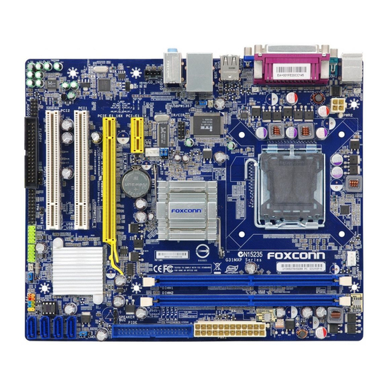
1-2 layout 15. USBPW0246_1 Jumper 1. 4-pin ATX 12V Power Connector 16. South Bridge: Intel ® ICH7 2. USBPW1357_1 Jumper 3. IR/CIR Connector 17. Front Panel Connector 4. CD_IN Connector 18. SATA Connectors 5. PCI Express x1 Slot 19. Clear CMOS Jumper 6.
-
Page 12: Back Panel Connectors
1-3 back Panel Connectors PS/2 Mouse Port LAN Port Parallel Port Line In Line Out Microphone PS/2 Keyboard Port Serial Port VGA Port USB Ports Audio Ports 1. PS/2 Mouse Port Use the upper port (green) to connect a PS/2 mouse. 2.
-
Page 13
Description No Link No Link 100M Green Data Activity Orange 10/100Mb/s Connection Blinking No Link No Link 10Mb/s Connection 1000M Green Data Activity Green 100Mb/s Connection Blinking Orange 1000Mb/s Connection Active Link G31MXP supports 10/100Mb/s Ethernet. G31MXP-K supports 1Gb/s Ethernet. -
Page 14
This chapter introduces the hardware installation process, including the installation of the CPU, memory, power supply, slots, pin headers and the mounting of jumpers. Caution should be exercised during the installation of these modules. Please refer to the motherboard layout prior to any installation and read the contents in this chapter carefully. -
Page 15: Install The Cpu And Cpu Cooler
2-1 Install the CPU and CPU Cooler Read the following guidelines before you begin to install the CPU : ■ Make sure that the motherboard supports the CPU. ■ Always turn off the computer and unplug the power cord from the power supply before installing the CPU to prevent hardware damage.
-
Page 16
Follow the steps to install the CPU onto the CPU socket : Before installing the CPU, make sure to turn off the computer and unplug the power cord from the power outlet to prevent damage to the CPU. 1. Remove protective socket cover. Remove protective socket cover. -
Page 17: Install The Cpu Cooler
Install the CPU Cooler Follow the steps below to correctly install the CPU cooler on the motherboard. (The following procedures use Foxconn cooler as the example.) 1. Apply and spread an even thermal 2. Place the four bolts of the CPU grease on the surface of CPU.
-
Page 18: Install The Memory
2-2 Install the Memory Read the following guidelines before you begin to install the memory : ■ Make sure that the motherboard supports the memory. It is recommended that memory of the same capacity, brand, speed, and chips be used. ■…
-
Page 19: Installing A Memory
Installing a Memory Before installing a memory module, make sure to turn off the computer and unplug the power cord from the power outlet to prevent damage to the memory module. Be sure to install DDR2 DIMMs on this motherboard. Notch If you take a look at front side of memory module, it has asymmetric pin counts on both sides separated by a notch in the middle, so it can only fit in one direction.
-
Page 20: Install An Expansion Card
2-3 Install an expansion Card ■ Make sure the motherboard supports the expansion card. Carefully read the manual that Make sure the motherboard supports the expansion card. Carefully read the manual that came with your expansion card. ■ Always turn off the computer and unplug the power cord from the power outlet before Always turn off the computer and unplug the power cord from the power outlet before installing an expansion card to prevent hardware damage.
-
Page 21: Install Other Internal Connectors
2-4 Install other Internal Connectors Power Connectors This motherboard uses an ATX power supply. In order not to damage any device, make sure all the devices have been installed properly before applying the power supply. 24-pin ATX power connector : PWR1 PWR1 is the ATX power supply connector.
-
Page 22
Audio Connector : CD_IN CD_IN is a Sony standard audio connector, it can be CD_L GND CD_R connected to a CD/DVD-ROM drive through a CD/DVD audio cable. CD_IN PORT1_L AUD_GND Audio Connector : f_AUDIo PORT1_R PRESENCEJ The audio connector supports HD Audio standard. PORT2_R SENSE1_RETURN It provides the Front Audio output choice. -
Page 23: Front Panel Connector
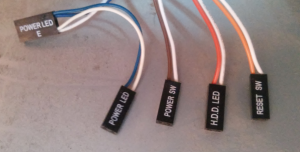
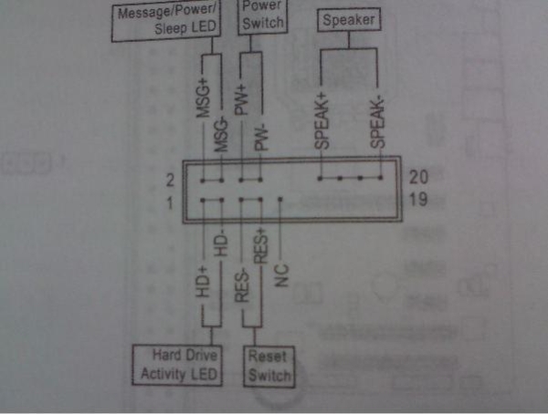
front Panel Connector : fP1 This motherboard includes one connector for connecting the front panel switch and LED Indicators. HDD-LED PWR-LED Hard Disk leD Connector (HDD-leD) RESET-SW PWR-SW Connect to the chassis front panel IDE indicator LED. It EMPTY indicates the active status of the hard disks. This 2-pin connector is directional with +/- sign.
-
Page 24
Chassis Intrusion Alarm Header : INTR The connector can be connected to a security switch on INTRUDERJ the chassis. The system can detect the chassis intrusion INTR through the function of this connector. If eventually the chassis was closed, the system will send a message out. TPM Connector : TPM The TPM (Trusted Platform Module) provides the ability to the PC to run applications more secure and to make transactions… -
Page 25: Jumpers
2-5 Jumpers For some features needed, users can change the jumper settings on this motherboard to modify them. This section explains how to use the various functions of this motherboard by changing the jumper settings. Users should read the following content carefully prior to modifying any jumper setting. Description of Jumpers 1.
-
Page 26
■ Disconnect the power cable before adjusting the jumper settings. ■ Do not clear the CMOS while the system is turned on. USb device wake-up Jumper: USbPW1357_1 / USbPW0246_1 1. Set the jumper to pins 1-2 (+5V) to wake up the computer from S1 sleep mode using the connected USB devices. -
Page 27: Over Memory Frequency Jumper
over Memory frequency Jumper: JP1, JP2 When you use the memory which support 1066, the jump- ers are used to overclock memory frequency. At the same time, the overclock bound depend on CPU FSB, you can achieve the function as below. 1.
-
Page 28
This chapter tells how to change system settings through the BIOS Setup menus. Detailed descriptions of the BIOS parameters are also provided. You have to run the Setup Program when the following cases occur: 1. An error message appears on the screen during the system Power On Self Test (POST) process. -
Page 29: Enter Bios Setup
enter bIoS Setup The BIOS is the communication bridge between hardware and software, correctly setting up the BIOS parameters is critical to maintain optimal system performance. Power on the computer, when the message «Press <Del> to enter Setup, <eSC> to boot menu» appears at the bottom of the screen, you can press <Del>…
-
Page 30
► Power Management Setup All the items related with Green function features can be set up through this menu. ► PC Health Status This setup enables you to read/change Fan speeds, and displays temperatures and voltages of your CPU/System. ► Load Optimized Defaults The optimal performance settings can be loaded through this menu. -
Page 31: System Information
[ None] ►IDE Channel 3 Slave [ None] Drive A [1.44M, 3.5 in.] Halt On [All , But Keyboard] Model Name : G31MXP/G31MXP-K BIOS Version : Memory : 2048MB MAC Address : 00-01-6C-20-F4-90 Intel(R) Core(TM)2 CPU 6700 @ 2.66GH� ↑↓→←:Move Enter:Select…
-
Page 32
Award (Phoenix) BIOS is supporting 3 HDD modes : CHS, LBA and Large. For HDD <528MB For HDD >528MB & Supporting LBA (Logical Block Addressing) Large For HDD>528MB but not supporting LBA Note: Set to [Auto] , the system can detect the hard disk and select the HDD mode automatically. -
Page 33: Fox Central Control Unit
fox Central Control Unit Phoenix — AwardBIOS CMOS Setup Utility Fox Central Control Unit ► Smart BIOS ► Smart BIOS [ Press Enter] Press Enter Item Help Item Help ► Fox Intelligent Stepping ► Fox Intelligent Stepping [ Press Enter] ►…
-
Page 34: Smart Bios
Smart bIoS Phoenix — AwardBIOS CMOS Setup Utility Smart BIOS Smart Power LED [Enabled] Item Help Enabled Smart Boot Menu Smart Boot Menu [Disabled] Current CPU Speed 1866MH� Menu Level ► Current FSB Speed 1066MH� Current CPU Multiplier Smart Debug LED Current DRAM Speed 800MH�…
-
Page 35: Fox Intelligent Stepping
fox Intelligent Stepping Phoenix — AwardBIOS CMOS Setup Utility Fox Intelligent Stepping Disabled Fox 1600 CPU Support Fox 1600 CPU Support [Disabled] Item Help Fox Intelligent Stepping Fox Intelligent Stepping [Default] CPU Clock 266MH� Menu Level ► PCI Express Clock 100MH�…
-
Page 36: Cpu Configuration
you had better disable it. ► CPU Multiplier Adjust This option is used to adjust the CPU Clock Ratio. Multiply CPU clock with this ratio, you can get the CPU speed. Increase this ratio may overclock your CPU. This option will be displayed only if your CPU is supporting this feature.
-
Page 37
► Limit CPUID MaxVal This item is used to enable or disable CPUID maximum value limit configuration. Set Limit CPUID MaxVal to 3, it should be [Disabled] for WinXP. ► C1E Function C1E represents Enhanced HALT State. It is a feature which Intel CPU uses to reduce power consumption when in halt state. -
Page 38: Dram Configuration
DRAM Configuration Phoenix — AwardBIOS CMOS Setup Utility DRAM Configuration DRAM Timing Selectable By SPD SPD] Item Help x CAS Latency Time Auto x DRAM RAS# to CAS# Delay Auto Menu Level ► x DRAM RAS# Precharge Auto x Precharge Delay Auto x System Memory Speed Auto…
-
Page 39: Advanced Bios Features
Advanced bIoS features Phoenix — AwardBIOS CMOS Setup Utility Advanced BIOS Features ► Removable Device Priority [Press Enter] Item Help Press Enter ► Hard Disk Boot Priority ► Hard Disk Boot Priority [Press Enter] CPU L1 & L2 Cache CPU L1 & L2 Cache [Enabled] Menu Level ►…
-
Page 40
is set to “System”, a password is required not only to enter CMOS Setup, but also to start up your PC. ►Delay For HDD (Seconds) This item allows you to select the delay for detecting ATA/ATAPI devices while booting. Time out value: 0~15s. -
Page 41: Advanced Chipset Features Advanced Chipset Features
Advanced Chipset features Phoenix — AwardBIOS CMOS Setup Utility Advanced Chipset Features System BIOS Cacheable [Enabled] Enabled Item Help Video BIOS Cacheable [Disabled] Menu Level ► ** VGA Setting ** PEG/Onchip VGA Control [Auto] Auto] On-Chip Frame Buffer Si�e DVMT Mode [DVMT] DVMT/FIXED Memory Si�e [256MB]…
-
Page 42
DVMT is an enhancement of the UMA concept, where in the graphics driver allocates memory as needed for running graphics applications. If a user is not performing any graphics-intensive operations, most of the DVMT memory can be utili�ed by the OS for other uses. We recommend using DVMT setting for better overall system performance. -
Page 43: Integrated Peripherals
Integrated Peripherals Phoenix — AwardBIOS CMOS Setup Utility Integrated Peripherals ► OnChip IDE Devices [Press Enter] Item Help Press Enter ► OnBoard Devices [Press Enter] ► SuperIO Devices [Press Enter] Menu Level ► ► USB Devices Setting [Press Enter] ↑↓→←:Move Enter:Select +/-/PU/PD:Value F10:Save ESC:Exit F1:General Help F5: Previous Values…
-
Page 44
DMA transfers when the PCI bus is overclocked. Disabling DMA support will force the drive to use the slower PIO transfer mode. This may allow the drive to work properly with the higher PCI bus speed. ► On-Chip Primary PCI IDE Enable/Disable Primary IDE port. -
Page 45: Onboard Devices
onboard Devices Phoenix — AwardBIOS CMOS Setup Utility OnBoard Devices OnBoard Audio Controller Audio Controller Controller [Enabled] Enabled Item Help OnBoard LAN Controller [Enabled] OnBoard LAN Boot ROM [Disabled] Menu Level ► ↑↓→←:Move Enter:Select +/-/PU/PD:Value F10:Save ESC:Exit F1:General Help F5: Previous Values F7: Optimi�ed Defaults ►…
-
Page 46
► OnBoard FDC Controller This item is used to enable or disable the onboard FDC controller. ► OnBoard Serial Port 1 This item is used to assign the I/O address and interrupt request (IRQ) for the onboard serial port 1. ►… -
Page 47
► USB Operation Mode This item is used to set the USB operation mode. If you select the [High Speed], then the USB operation mode is determined by the USB device; select [Full/Low Speed], the USB device operates on full/low speed. ►… -
Page 48: Power Management Setup
Pow er Management Setup Phoenix — AwardBIOS CMOS Setup Utility Power Management Setup ACPI Function [Enabled] Enabled Item Help ACPI Suspend Type [S3(STR)] Power Button [Instant-off] Menu Level ► PWRON after PWR-Fail PWRON after PWR-Fail [Off] PCI Express PME [Enabled] Wake Up by PCI Card [Enabled] Wake Up on LAN…
-
Page 49
► ACPI Function This item is used to enable or disable the ACPI function. ► ACPI Suspend Type This item is used to set the energy saving mode of the ACPI function. When you select “S1 (POS)” mode, the power is always on and computer can be resumed at any time. When you select “S3 (STR)”… -
Page 50
► Power On by Mouse When enabled, it allows you to use the mouse to wake up the system from soft off and green mode. This feature requires an ATX power supply. ► Power On by Keyboard This item allows you to use the keyboard to wake up the system from soft off and green mode. This feature requires an ATX power supply. -
Page 51: Pc Health Status
PC Health Status Phoenix — AwardBIOS CMOS Setup Utility PC Health Status Case Open Warning [Disabled] Item Help Disabled Shutdown Temperature [Disabled] CPU Vcore 1.20 V Menu Level ► +3.3V 3.39 V 5.02 V +12V 11.84 V VDDR 1.79V 51 o C CPU Temperature 38 o C System Temperature…
-
Page 52
► Delta Temperture erture It is used to set the delta value for temperature. When change of the temperature reaches plus/minus delta value, then the PWM will be increased or decreased by a step value based on the slope formula. -
Page 53: Load Optimi�Ed Defaults Optimi�Ed Defaults Defaults
Load Optimized Defaults Select this option and press <Enter>. A dialogue pops out, select <Y> then press <Enter> to load the defaults; press <N> to skip. Load Optimi�ed Defaults (Y/N)? N By this default, BIOS have set the optimi�ed performance parameters of system to improve the performances of system components.
-
Page 54
The utility CD that came with the motherboard contains useful software and several utility drivers that enhance the motherboard features. This chapter includes the following information: ■ Utility CD content ■ Install driver and utility ■ FOX ONE ■ FOX LiveUpdate ■… -
Page 55: Chapter 4 Cd Instruction Utility Cd Content Utility Cd Content
Utility CD content This motherboard comes with one Utility CD. You can simply put it into your CD/DVD-ROM drive, and the main menu will be displayed on your PC screen to guide you how to install. 1. Install Driver Use these options to install all the drivers for your system. You should install the drivers in order, and you need to restart your computer after all the drivers have been installed.
-
Page 56: Install Driver And Utility
Step by Step Automatic Installation by One Click. Exit the program Browse CD Click to visit Select to Install Select to Drop to System Tray Foxconn’s Utilities Install Drivers website 2. Install Utility You can select the specific utility to install.
-
Page 57: Fox One
foX oNe FOX ONE is a powerful utility for easily modifying system settings. It also allows users to monitor various temperature values, voltage values, frequencies and fan speeds at any time. With FOX ONE, you can : ■ Modify system performance settings, such as the CPU and memory bus speeds, CPU voltages, fan speeds, and other system performance options.
-
Page 58: Main Page
1. Main Page Show CPU Toolbar Information Alert Lamp Switch Button Skin Button Exit Minimum Configuration Homepage Monitor Frequency/Voltage/Fan speed/Temperature value Toolbar Use the toolbar to navigate to other pages. Alert lamp When the system is in healthy state, the color of alert lamp is green. When the system is in abnormal state, the alert lamp color is red.
-
Page 59
Click this button to exit the program. Minimum Click this button to drop the FOX ONE to Windows system tray located at the lower right corner of your screen. Homepage Click this button to visit Foxconn motherboard website : http://www.foxconnchannel.com… -
Page 60
Configuration This menu allows you to configure : 1). Monitor interval (ms) : This is to define the interval of different messages of system settings which are to which are to are to be displayed on Simple Mode screen. Minimum value is 1 second. 2). -
Page 61
Step 1 : Click Calibration icon, a message pops out to ask for continue. Select Yes. Step 2 : After data is collected, it will ask you to restart your computer now. Later on, when the FOX ONE program is activated, and F.I.S. feature (in CPU Page) is also enabled, FOX ONE will automatically adjust your CPU clock according to your system loadings. -
Page 62: Cpu Control
2. CPU Page — CPU Control This page lets you select (or overclock) CPU clock to meet the current performance level of the system. The fastest and suitable CPU clock running for current system can be calculated by FOX ONE automatically or manually input by yourselves. Manual : You can press the up/down button to adjust your CPU clock.
-
Page 63
You can see the system is raising CPU clock until the system hangs. Push RESET button on the front panel of your system to restart the computer. Run FOX ONE program again, it will inform you the previous test found that 255MH�… -
Page 64: Frequency Control
foX Intelligent Stepping (f.I.S., optional) Select FOX Intelligent Stepping will allow your system to automatically adjust your CPU clock rate based on different system loadings. For example, if you select Power Gaming, CPU clock will be driven to run at its maximum speed. While in Energy Saving, CPU will lower down its speed to a minimum.
-
Page 65: Limit Setting
4. limit Setting 4.1 limit Setting — CPU Temperature This page lets you to set CPU high limit temperature and enable the alert function. Go to Limit Setting Show current CPU page temperature value Enable alert function when the CPU temperature is higher than high limit value Show current high…
-
Page 66
4.3 limit Setting — CPU fan This page lets you to set CPU fan low limit rpm and enable the alert function. Show current CPU fan rpm value Enable alert function when the CPU fan runs slower than the low limit rpm value Show current low limit rpm value of CPU fan… -
Page 67: Voltage Control
4.5 limit Setting — fAN1 fan (optional) This page lets you to set FAN1 fan low limit rpm and enable the alert function. Show current FAN1 fan rpm value Enable alert function when the FAN1 fan runs slower than low limit rpm value Show current low limit rpm value of FAN1 fan…
-
Page 68: Fan Control
6. fan Page — fan Control This page lets you enable Smart Fan function or set the fan speed by manual. When Smart Fan is selected, you must use a 4-pin CPU cooler in your system. Go to Fan page Enable or disable smart fan function Set fan speed by…
-
Page 69: Fox Liveupdate
foX liveUpdate FOX LiveUpdate is a useful utility to backup and update your system BIOS, drivers and utilities by local or online. Supporting Operating Systems : ■ Windows 2000 ■ Windows XP (32-bit and 64-bit) ■ Windows 2003 (32-bit and 64-bit) ■…
-
Page 70
1-2 local Update — backup This page can backup your system BIOS. You can click “Backup”, and key in a file name, then click “Save” to finish the backup operation. The extension of this backup file is «.BIN» for Award BIOS and «.ROM»… -
Page 71: Online Update
2. online Update 2-1 online Update — Update bIoS This page lets you update your system BIOS from Internet. Click “start”, it will search the new BIOS from Internet. Then follow the wizard to finish the update operation. Click here Current information Search new BIOS from Internet…
-
Page 72
Select the driver to update Browse detailed information Install the selected driver Close the window 2-3 online Update — Update Utility This page lets you update utilities from Internet. Click “start”, it will search the new utilities from Internet. Then follow the wizard to finish the update operation. Click here Current information Search new utilities… -
Page 73
2-4 online Update — Update All This page lets you update your system drivers from Internet. Click “start”, it will search all new BIOS/drivers/utilities from Internet. Then follow the wizard to finish the update operation. Click here Current information Search all new BIOS/ drivers/utilities from Internet Browse detailed… -
Page 74: Configure
3. Configure 3-1 Configure — option This page lets you set auto search options. After you enable the auto search function, FOX LiveUpdate will start its searching from Internet and if any qualified item found, it will pop out a message on the task bar to inform you to do the next step.
-
Page 75
When you enable «Auto Search FOX LiveUpdate», if your FOX LiveUpdate version is older, it will auto search from internet and prompt you to install the new version. Prompt you to install the new FOX LiveUpdate 3-2 Configure — System This page lets you set the backup BIOS location and change different skin of the FOX LiveUpdate utility. -
Page 76: About & Help
3-3 Configure — Advance This page lets you select to flash BIOS / Boot Block and clear CMOS. If you choose Flash Boot Block, it means BIOS is not protective, and you must make sure the flash process is continuous and without any interruption.
-
Page 77: Fox Logo
foX loGo FOX LOGO is a simple and useful utility to backup, change and delete the boot time Logo. The boot Logo is the image that appears on screen during POST (Power-On Self-Test). You can prepare a JPG image (1024×768) file, then use FOX LOGO to open it and change the boot time Logo.
-
Page 78: Fox Dmi
foX DMI FOX DMI is a full Desktop Management Interface viewer, and it provides three DMI data formats : Report, Data Fields and Memory Dump. With DMI information, system maker can easily analy�e and troubleshoot your mother- board if there is any problem occurred. Supporting Operating Systems : ■…
This manual is also suitable for:
G31mxp-k
В представленном списке руководства для конкретной модели Материнской платы — Foxconn G31MXP. Вы можете скачать инструкции к себе на компьютер или просмотреть онлайн на страницах сайта бесплатно или распечатать.
- Инструкции и файлы
- Характеристики
- Основные поломки
- Сервисы по ремонту
В случае если инструкция на русском не полная или нужна дополнительная информация по этому устройству, если вам нужны
дополнительные файлы: драйвера, дополнительное руководство пользователя (производители зачастую для каждого
продукта делают несколько различных документов технической помощи и руководств), свежая версия прошивки, то
вы можете задать вопрос администраторам или всем пользователям сайта, все постараются оперативно отреагировать
на ваш запрос и как можно быстрее помочь. Ваше устройство имеет характеристики:Socket: LGA775, Поддерживаемые процессоры: Intel Core2 Quad/Core2 Duo/Pentium Dual-Core/Celeron Dual-core/Celeron, Системная шина: 533 МГц — 1600 МГц, Поддержка многоядерных процессоров: есть, Чипсет: Intel G31, Поддержка SLI/CrossFire: нет, полные характеристики смотрите в следующей вкладке.
Для многих товаров, для работы с Foxconn G31MXP могут понадобиться различные дополнительные файлы: драйвера, патчи, обновления, программы установки. Вы можете скачать онлайн эти файлы для конкретнй модели Foxconn G31MXP или добавить свои для бесплатного скачивания другим посетителями.
Если вы не нашли файлов и документов для этой модели то можете посмотреть интсрукции для похожих товаров и моделей, так как они зачастую отличаются небольшим изменениями и взаимодополняемы.
Обязательно напишите несколько слов о преобретенном вами товаре, чтобы каждый мог ознакомиться с вашим отзывом или вопросом. Проявляйте активность что как можно бльше людей смогли узнать мнение настоящих людей которые уже пользовались Foxconn G31MXP.

В полнеотличная материнская плата!)
Основные и самые важные характеристики модели собраны из надежных источников и по характеристикам можно найти похожие модели.
| Процессор | |
| Socket | LGA775 |
| Поддерживаемые процессоры | Intel Core2 Quad/Core2 Duo/Pentium Dual-Core/Celeron Dual-core/Celeron |
| Системная шина | 533 МГц — 1600 МГц |
| Поддержка многоядерных процессоров | есть |
| Чипсет | |
| Чипсет | Intel G31 |
| Поддержка SLI/CrossFire | нет |
| Память | |
| Память | DDR2 DIMM, 533 — 800 МГц |
| Количество слотов памяти | 2 |
| Поддержка двухканального режима | есть |
| Максимальный объем памяти | 4 Гб |
| Дисковые контроллеры | |
| IDE | количество слотов: 1, UltraDMA 100 |
| SATA | количество разъемов SATA 3Gb/s: 4, RAID: нет |
| Слоты расширения | |
| Слоты расширения | 1xPCI-E x16, 1xPCI-E x1, 2xPCI |
| Аудио/видео | |
| Звук | 5.1CH, HDA, на основе Realtek ALC662 |
| Встроенный видеоадаптер | есть |
| Сеть | |
| Ethernet | 10/100 Мбит/с, на основе Realtek RTL8101E |
| Подключение | |
| Наличие интерфейсов | 8 USB, выход S/PDIF, 1xCOM, D-Sub, Ethernet, PS/2 (клавиатура), PS/2 (мышь), LPT |
| Разъемы на задней панели | 4 USB, D-Sub, Ethernet, PS/2 (клавиатура), PS/2 (мышь), LPT |
| Основной разъем питания | 24-pin |
| Разъем питания процессора | 4-pin |
| Дополнительные параметры | |
| Форм-фактор | microATX |
Здесь представлен список самых частых и распространенных поломок и неисправностей у Материнских плат. Если у вас такая поломка то вам повезло, это типовая неисправность для Foxconn G31MXP и вы можете задать вопрос о том как ее устранить и вам быстро ответят или же прочитайте в вопросах и ответах ниже.
| Название поломки | Описание поломки | Действие |
|---|---|---|
| Разрыв Печатных Проводников | ||
| Обрыв Конденсаторов Или Резисторов | ||
| Короткое Замыкание В Электрических Цепях | ||
| Разрушение Разъемов И Слотов | ||
| Поломка Процессорного Разъема | ||
| Выгорание Портов | ||
| Микротрещины В Плате | ||
| Выход Из Строя Сетевого Адаптера | ||
| Перегрев Компонентов | ||
| Не Запускается При Включении | При Включении Не Загружается. В Биос Не Входит. Пост Код — А3 | |
| Какой Компонент | Подскажите Марку Траyзистора Q46? | |
| Не Работает Ps/2 | Сначала Отвалилась Клавиатура, А Через Некоторое Время 6 Коротких Гудков И Не Запускается | |
| Подключить Переднюю Панель | Не Могу Подключить Переднюю Панель | |
| Судя По Всему Отвал Биоса | Материнка Стартует Секунд На 5,Кулер Процессора Берет Обороты И Останавливается.и Так-Циклически,Без Остановок.запуск Невозможен.вечером Либо Завтра Буду Пытаться Его Восстановить,Потом Может Дополню | |
| Пропал Звук На Материнке | Пропал Звук На Материнке, Отображается Только Nvidia Hdmi. Переустановка Драйверов С Офсайта Не Помогла. | |
| Биос | При Старте Звук Через Промежетки Времени Примерно В 1-3 Мин Три Сигнала Потом Стартует Винда , Недавно Вообще Написал Cmos Setting Wrong И C7, Жму Del Меняется На B2 Чтоб Воити В Биос Три Сигнала По Одному Через Промеежутки Времени 1-3 Мин И Черный Экра | |
| Asus M2A-Vm Hdmi | Не Запускается Процессор Phenom Ii X4 945 Rev. C3, На Socket-Ам 3, Нет Даже Сигнала, Черный Экран | |
| Не Включается | После Замены Конденсаторов С34 И С35 Не Включается | |
| Черный Экран | Все Уже Перепробовал И Озу Менял И Переставлял И Ластиком Чистил, И Батарейку Вынимал И Измерял, И Видеокарту С Бп На Заведомо Годную Ставил Исход Один, Черный Экран И Speaker Издает 1 Длинный 2 Коротких, Если Я Не Путаю. | |
| Неправильно Отображается Память | При Установленной Памяти 4 Гигабайта В Биосе Отображается 8. Установил Одну Планку 2 Гига — Отображается 4 | |
В нашей базе сейчас зарегестрированно 18 353 сервиса в 513 города России, Беларусии, Казахстана и Украины.

АБИТ-ЦЕНТР
⭐
⭐
⭐
⭐
⭐
Адресс:
ул. Верхние Поля, д.36, корп.1
Телефон:
74957419058
Сайт:
n/a
Время работы
Время работы не указано
СЕРВИСНЫЙ ЦЕНТР В НОВОКОСИНО
⭐
⭐
⭐
⭐
⭐
Адресс:
метро Перово
Телефон:
74996535656
Сайт:
n/a
Время работы
Время работы не указано
REMOBI
⭐
⭐
⭐
⭐
⭐
Адресс:
Каширское ш., 26
Телефон:
74993222524
Сайт:
n/a
Время работы
Ежедневно: с 1000 до 2100
REMOBI
⭐
⭐
⭐
⭐
⭐
Адресс:
Шереметьевская ул., 6, ТЦ Райкин Плаза
Телефон:
74993222524
Сайт:
n/a
Время работы
Ежедневно: с 1000 до 2100
МАСТЕР КОМП
⭐
⭐
⭐
⭐
⭐
Адресс:
Совхозная 12
Телефон:
74959892248
Сайт:
n/a
Время работы
Будни: с 1000 до 2000
Суббота: с 1200 до 1800
Воскресенье: выходной
Прошивка Foxconn G31MXV
16:18
Очень доволен
хочу
авпваы
Хочу купить
ирлдоьвап ькеьпрлджыкеь дзьакерджь щзрбкежбрь апкыезрбкыеджрбеджр щзапбкерл
Только приобрела,а инструкции нет
Только приобрела,а инструкции нет
Отвалился распрыскиватель
Statement:
This manual is the intellectual property of Foxconn, Inc. Although the information
in this manual may be changed or modified at any time, Foxconn does not obligate
itself to inform the user of these changes.
Trademark:
All trademarks are the property of their respective owners.
Version:
User’s Manual V1.0 for G31MXP Series motherboard.
P/N: 3A2215900-000-G
Symbol description:
!
Caution :
Warning :
WEEE:
The use of this symbol indicates that this product may not be treated as household
waste. By ensuring this product is disposed of correctly, you will help prevent potential
negative consequences for the environment and human health, which could otherwise
be caused by inappropriate waste handling of this product. For more detailed
information about recycling of this product, please contact your local city office, your
household waste disposal service or the shop where you purchased this product.
More information:
If you want more information about our products, please visit Foxconn’s website:
http://www.foxconnchannel.com
All trade names are registered trademarks of respective manufacturers listed.
All images are for reference only, please refer to the physical motherboard for specific features.
refers to important information that can help you to use motherboard
better, and tells you how to avoid problems.
indicating a potential risk of hardware damage or physical injury
may exist.
© All rights reserved.
Specifications:267/267951-g31mxp.pdf file (24 Nov 2022) |
Accompanying Data:
Foxconn G31MXP Motherboard PDF Operation & User’s Manual (Updated: Thursday 24th of November 2022 11:15:33 PM)
Rating: 4.9 (rated by 93 users)
Compatible devices: G31 MX series, A76GMV, K7S741GXMG-6L, G41AP, P9657AB User’s, 845GVME-S, A74ML 3.0, T70S.
Recommended Documentation:
Text Version of Operation & User’s Manual
(Ocr-Read Summary of Contents of some pages of the Foxconn G31MXP Document (Main Content), UPD: 24 November 2022)
-
15, 8 2 2-1 Install the CPU and CPU Cooler Install the CPU Locate the alignment keys on the motherboard CPU socket and the notches on the CPU. LGA775 CPU Socket Alignment Key Pin-1 corner of the CPU Socket LGA775 CPU Notch Pin-1 triangle marking of CPU Read the following guidelines before you…
-
57, Foxconn G31MXP 50 4 FOX ONE FOX ONE is a powerful utility for easily modifying system settings. It also allows users to monitor various temperature values, voltage values, frequencies and fan speeds at any time. With FOX ONE, you can : ■ Modify system performance settings, such as the CPU and memory bus speeds, CP…
-
61, Foxconn G31MXP 54 4 Step 1 : Click Calibration icon, a message pops out to ask for continue. Select Yes. Step 2 : After data is collected, it will ask you to restart your computer now. Later on, when the FOX ONE program is activated, and F.I.S. feature (in CPU Page) is also enabled, FOX ONE will automatically adjust …
-
4, Foxconn G31MXP Declaration of conformity Trade Name: FOXCONN Model Name: G31MXP/G31MXP-K Responsible Party: PCE Industry Inc. Address: 458 E. Lambert Rd. Fullerton, CA 92835 Telephone: 714-738-8868 Facsimile: 714-738-8838 Equipment Classication: FCC Class B Subassembly Type of Product: Motherboard Manufact…
-
33, 26 3 Fox Central Control Unit ► Smart BIOS/ Fox Intelligent Stepping/ Voltage Options/ CPU Conguration/ DRAM Conguration Press <Enter> to go to its submenu. ► Super BIOS Protect To protect the system BIOS from virus attack, there is a BIOS write-protection mechanism provided. Sup…
-
43, 36 3 Integrated Peripherals ► OnChip IDE Devices / OnBoard Devices / SuperIO Devices / USB Devices Setting Press <Enter> to go to relative submenu. OnChip IDE Devices ► IDE HDD Block Mode If your IDE hard drive supports block mode, select [Enabled] for automatic detection of the optimal n…
-
70, 63 4 1-2 Local Update — Backup This page can backup your system BIOS. You can click “Backup”, and key in a le name, then click “Save” to nish the backup operation. The extension of this backup le is «.BIN» for Award BIOS and «.ROM» for AMI BIOS. Default directory is &…
-
Foxconn G31MXP User Manual
-
Foxconn G31MXP User Guide
-
Foxconn G31MXP PDF Manual
-
Foxconn G31MXP Owner’s Manuals
Recommended: Calculite 8056, ICF-28, 191


-
TYAN S7002
S7002 Version 1.00 Copyright Copyright © MiTAC Computer Corporation, 2009. All rights reserved. No part of this manual may be reproduced or translated without prior written consent from MiTAC Computer Corp. Trademark All registered and unregistered trademarks and company names contained in this manual are …
S7002 100
-
ASROCK A55iCafe
1ASRock A55iCafe MotherboardEnglishCopyright Notice:No part of this installation guide may be reproduced, transcribed, transmitted, or trans-lated in any language, in any form or by any means, except duplication of documentation by the purchaser for backup purpose, without written consent of ASRock Inc.Products a …
A55iCafe 115
-
Gewiss SYSTEM Series
Serie SYSTEM: GW 20 868 — GW 21 868 Serie PLAYBUS: GW 30 520 RIVELATORE DI GAS GPLLPG DETECTORDÉTECTEUR DE PRÉSENCE DE BUTANE/PROPANEDETECTOR DE PRESENCIA DE GPLGASWARNMELDER FÜR FLÜSSIGGASDETECTOR DE GAZ GPL …
SYSTEM Series 88
-
MSI Z170A KRAIT GAMING
IQuick StartQuick StartThank you for purchasing the MSI® Z170A GAMING M3/ H170 GAMING M3/ B150 GAMING M3 motherboard. This Quick Start section provides demonstration diagrams about how to install your computer. Some of the installations also provide video demonstrations. Please link to the URL to watch it with the web …
Z170A KRAIT GAMING 170
Additional Information:
Popular Right Now:
Operating Impressions, Questions and Answers:
Содержание
- Foxconn G31MXP User’s Manual
- Download for Free 78 pages PDF User Guide, Owner’s Manual, Instruction for Foxconn G31MXP Motherboard
- Foxconn G31MXP Specifications:
- Foxconn G31MXP Documentation Transcript:
- Руководство пользователя для материнских плат Foxconn G31MXP серии
- для материнских плат Foxconn
- Программное обеспечение, которое может оказаться полезным
- Утилита для автоматического поиска драйверов
- Программа для оптимизации и ускорения Windows
- HARDWARE НОВОСТИ
- Помогите. Не стартует материнка FOXCONN G31 MXP с кнопки PWR_ON.
- Рекомендуется к прочтению по той же теме
- Материнская плата foxconn g31mxp схема подключения
- Foxconn n15235 подключение передней панели
- Шаг 1 — находим шлейфы, идущие от передней панели к мат. плате
- Шаг 2 — находим контакты на материнской плате для подключения передней панели
- Шаг 3 — Подключаем фишки разъемов передней панели к соответствующим разъемам материнской платы
- Вариант первый
- Вариант второй
- Нет звука через HDMI: устройство уже используется другим приложением
- CLRTC на материнской плате asus что это?
- jcom1 на материнской плате что это?
- 3 Комментариев
- Александр
- Этапы подключения передней панели к материнской плате
- Этап 1
- Этап 2
- Этап 3
- Этап 4
- Видео-инструкция по подключению фронтальной панели к «материнке»
Foxconn G31MXP User’s Manual
Download for Free 78 pages PDF User Guide, Owner’s Manual, Instruction for Foxconn G31MXP Motherboard
Foxconn G31MXP Specifications:
- Manufacturer: Foxconn
- Category of Device: Motherboard
- Document: Operation & User’s Manual, File Type: PDF
- Count of Pages: 78
Download G31MXP Manual (78 pages)
Foxconn G31MXP Documentation Transcript:
51 4 1. Main Page Toolbar Use the toolbar to navigate to other pages. Alert Lamp When the system is in healthy state, the color of alert lamp is green. When the system is in abnormal state, the alert lamp color is red. Switch Button Click this button, it will simplify the whole FOX ONE control panel to a smaller information bar (i.e. Simple Mode) as depicted below, you can drag this bar to any place on your …
65 4 2-3 Online Update — Update Utility This page lets you update utilities from Internet. Click “start”, it will search the new utilities from Internet. Then follow the wizard to nish the update operation. Browse detailed information Install the selected driver Close the window Select the driver to update Click here Current information Search new utilities from Internet Browse detailed information Install the selected utility Close the window Select the utility to update …
Foxconn G31MXP 55 4 2. CPU Page — CPU Control This page lets you select (or overclock) CPU clock to meet the current performance level of the system. The fastest and suitable CPU clock running for current system can be calculated by FOX ONE automatically or manually input by yourselves. Manual : You can press the up/down button to adjust your CPU clock. Auto : Click this button to let FOX ONE c…
Foxconn G31MXP 29 3 you had better disable it. ► CPU Multiplier Adjust This option is used to adjust the CPU Clock Ratio. Multiply CPU clock with this ratio, you can get the CPU speed. Increase this ratio may overclock your CPU. This option will be displayed only if your CPU is supporting this feature. Voltage Options ► CPU Voltage This option is used to change the CPU voltage. ► DRAM Voltage This option is used to change the DRAM voltag…
33 3 is set to “System”, a password is required not only to enter CMOS Setup, but also to start up your PC. ►Delay For HDD (Seconds) This item allows you to select the delay for detecting ATA/ATAPI devices while booting. Time out value: 0
15s. ► Full Screen Logo Show This item allows you to enable or disable full screen logo show. …
Foxconn G31MXP 45 3 ► Delta Tempertureerture It is used to set the delta value for temperature. When change of the temperature reaches plus/minus delta value, then the PWM will be increased or decreased by a step value based on the slope formula. …
61 4 6. Fan Page — Fan Control This page lets you enable Smart Fan function or set the fan speed by manual. When Smart Fan is selected, you must use a 4-pin CPU cooler in your system. Go to Fan page Set fan speed by dragging the lever Enable or disable smart fan function Apply the changes …
Foxconn G31MXP Statement: This manual is the intellectual property of Foxconn, Inc. Although the information in this manual may be changed or modied at any time, Foxconn does not obligate itself to inform the user of these changes. Trademark: All trademarks are the property of their respective owners. Version: User’s Manual V1.0 for G31MXP Series motherboard. P/N: 3A2215900-000-G Symbol description: …
Foxconn G31MXP 36 3 Integrated Peripherals ► OnChip IDE Devices / OnBoard Devices / SuperIO Devices / USB Devices Setting Press to go to relative submenu. OnChip IDE Devices ► IDE HDD Block Mode If your IDE hard drive supports block mode, select [Enabled] for automatic detection of the optimal number of block read/write per sector. ► IDE DMA Transfer Access [Disabled] : to disable DMA transfers for all IDE drives. They will revert to PIO mode transfers. [Enable…
Источник
Руководство пользователя для материнских плат Foxconn G31MXP серии
для материнских плат Foxconn
Альтернативные ссылки для скачивания
Пожалуйста, поставьте свою оценку!
Если при нажатии на ссылку ничего не происходит, подождите несколько секунд!
Список поддерживаемых моделей:
Программное обеспечение, которое может оказаться полезным
Утилита для автоматического поиска драйверов
Carambis Driver Updater — программа для автоматического поиска и установки всех драйверов практически на любой компьютер, ноутбук, принтер, веб-камеру и другие устройства
Программа для поиска и установки новых драйверов и обновления уже установленных на компьютере под управлением операционных систем Windows. Поиск драйверов для любых неопознанных системой устройств, полностью автоматизированное скачивание и установка драйверов для Windows 10, 8.1, 8, 7, Vista и XP.
Программа для оптимизации и ускорения Windows
Carambis Cleaner — программа для повышения быстродействия компьютера и исправления ошибок операционных систем Windows
Программа, которая позволит значительно повысить скорость работы компьютера путем исправления системных ошибок, очистки записей реестра, оставшихся после удаления программ, удаления дубликатов файлов, больших неиспользуемых и временных файлов. Совместима с Windows 10, 8.1, 8, 7, Vista и XP
* Данное программное обеспечение, предоставляется компанией Carambis, как условно бесплатное. Это означает, что бесплатно вы можете: загрузить его с нашего сайта или сайта компании партнера, установить на свой компьютер, использовать некоторые функции, которые доступны в бесплатной версии. Например, в программе Driver Updater вы можете просканироват компьютер на предмет устаревших и отсутствующих драйверов для оборудования. Однако, только в платной версии доступно обновление и автоматическое скачивание драйверов. Все вопросы, касаемые работы программы, покупки лицензионного ключа, поддержки и тд., решаются исключительно с компанией, которая предоставляет данное программное обеспечение.
HARDWARE НОВОСТИ
P9222-R позволяет производителям дополнять свои небольшие устройства с батарейным пи
Совсем недавно, ведущий производитель системных плат и графических карт GIGABYTE TEC
Ведущий производитель материнских плат и видеокарт компания GIGABYTE TECHNOLOGY Co.,
Шведский разработчик компьютерных компонентов Fractal Design продолжает расширять ас
Источник
Помогите. Не стартует материнка FOXCONN G31 MXP с кнопки PWR_ON.
Не стартует материнка FOXCONN G31 MXP. На Pw-on 5.13v присутствуют. Ничего не греется (в принудительном тоже). Пожалуста помогите определить неисправность, все напруги каторые нужно напишу. Я просто незнаю с чего начать. Незнаю поможет информация или нет но, на Q49, Q56 Q34 напруг вообше нет.
Рекомендуется к прочтению по той же теме

Спокойствие, только спокойствие.
В данном случае что значит ваше не стартует — поясните поконкретней.
В остальном делайте хорошую фотку вашей маман и подписывайте где что намеряли а мы уж подскажем
И твоя голова всегда в ответе за то куда сядет твой зад.
FOXCONN G31 MXP не стартует: идет загрузка проца оперативки, находит жесткий потом рестарт и все заново, проблема появилась после форматирования диска с акронисом, биос сбрасиваль не помогает, оптимальная конфигурация тоже не помогает
Это не нестарт — у вас маман заводится, и проходит все пост и даже появляется post-screen.
А какая последовательность загрузки выставлена в БИОСе у меня обычно первым загрузка с CD/DVD приводов, потом винчестер, а потом как сложится
Подключите один CD/DVD привод, воткните туда любой загрузочный диск — реакция изменится.
И твоя голова всегда в ответе за то куда сядет твой зад.
Источник
Материнская плата foxconn g31mxp схема подключения
Устал от подобных вопросов, создаю тему, которая должна все объяснить.
Начнем с панели управления, то есть включение и прочее.
Этот вариант у 90% мат плат.
Индикатор обращения к жесткому диску 1 — 3 контакты
Световой индикатор питания 2 — 4 контакты
Очистить 5 — 7 контакты
Кнопка включения питания 6 — 8 контакты
Надеюсь все понимают что один ряд получается все четные, другой все нечетные? 
У Asus все по другому, но у них четко прописаны буквы напротив контактов и догадываться об их предназначении нетрудно.
Для тех кто испытывает трудности с расшифровкой этих букв: 
PLED — Power Led — сигнал питания (светодиод)
SPEAKER — Динамик системный
IDE LED— сигнал работы IDE (HDD) жесткого диска(светодиод)
PWRSW — Power Switch — кнопка питания
RESET — кнопка сброса (прерывание Power Good)
Далее рассмотрим вывод звука на переднюю панель. 

Описывать HD я пока не буду, начнем с AC97:
Pin Signal Name Function
1 AUD_MIC Front Panel Microphone input signal Выход микрофона на переднюю панель
2 AUD_GND Ground used by Analog Audio Circuits Земля, масса, минус — как хотите
3 AUD_MIC_BIAS Microphone Power Что то связанное со смещением звука на микрофоне, надеюсь кто то более точно сообщит.
4 AUD_VCC Filtered +5 V used by Analog Audio Circuits 5 вольт питания для звука
5 AUD_FPOUT_R Right Channel Audio signal to Front Panel Выход правого канала на переднюю панель
6 AUD_RET_R Right Channel Audio signal to Return from Front Panel Вход правого канал на переднюю панель
7 HP_ON Reserved for future use to control Headphone Amplifier Зарезервировано для использования в будущем
8 KEY No Pin Бестолковый контакт
9 AUD_FPOUT_L Left Channel Audio signal to Front Panel Выход левого канала на переднюю панель
10 AUD_RET_L Left Channel Audio signal Return from Front Panel Вход левого канала на переднюю панель
Обычно мы имеем колодку или отдельные контакты с загадочными надписями:
1 MIC-VCC,
2 MIC-IN,
3 GND,
4 EAR L,
5 EAR R,
6 LINE L,
7 LINE R
Итак подключаем ваши контакты
Микрофон пока опустим, в дальнейшем распишу.
По поводу звука все просто:
6 LINE L в 9 AUD_FPOUT_L
4 EAR L в 10 AUD_RET_L
7 LINE R в 5 AUD_FPOUT_R
5 EAR R в 6 AUD_RET_R
Учтите что на некоторых системных платах не будет звука при установленных драйверах если не будет джамперов на этих контактах и не подключена передняя панель: 
Обладателям Audigy, советую посетить эту страницу.
Контакты USB: спасибо 2503

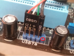
Главное не перепутать +5 и GND — это крайние контакты.
+5V также обозначается иногда как VCC, а средние DATA — и DATA + на всех новых системных платах +5 вольт располагается с краю контактной площадки, а «земля» около незадействованного контакта, как видно на картинке. На старых системных платах (первые на сокете 478 и старые сокет 370) встречается, когда один ряд перевернут на 180 градусов.

——-
ВНИМАНИЕ ознакомьтесь, прежде чем создать тему! Процессор — мозг компьютера, блок питания — сердце и печень.
Источник
Foxconn n15235 подключение передней панели
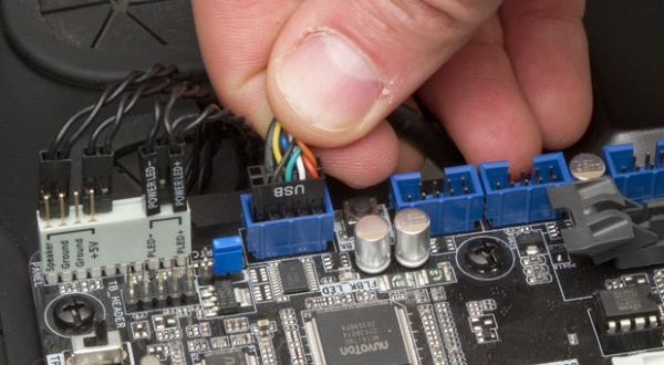
Большинство неопытных компьютерных пользователей считают, что подключить переднюю панель корпуса компьютера, на которой находятся кнопки включения и перезагрузки компьютера, а также USB входы и аудио выходы, к материнской плате является сложным и трудно выполнимым занятием.
Но, как часто это бывает, потратив 5 минут на изучение вопроса, все становится понятно и очень даже выполнимо. В данной статье мы рассмотрим последовательность действий, которые необходимо выполнить для успешного и правильного подключения передней панели к к материнской плате, будь это плата фирмы Asus, Gigabyte, Asrock, MSI и других.
Шаг 1 — находим шлейфы, идущие от передней панели к мат. плате
Это те самые шлейфы, которые мы будем подключать к соответствующим разъемам материнской платы. Особенность этих самых шлейфов, по которым их можно найти среди других проводов в корпусе системного блока это надписи на концах их разъемов:
- Power SW (PWRBTN) — Кнопка включения компьютера;
- Reset SW (Reset) — Кнопка перезагрузки;
- HDD LED ( >
Разъемы передней панели системного блока
Для тех, у кого Power LED состоит из 2-ух фишек на 2 и 3 контакта (как на рисунке выше) обоснование следующее: на некоторых материнских платах разъем подключения POWER LED (индикатор включения компьютера) выполнен на 3-ех контактах (средний не используется), а на некоторых на 2-ух. Поэтому в вашем случае нужно использовать либо одну фишку Power Led, либо другую.
Шаг 2 — находим контакты на материнской плате для подключения передней панели
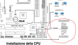
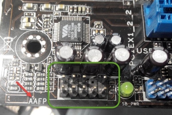
Стоит отметить, что подключение кнопок включения, перезагрузки, индикатора работы жесткого диска и индикатора включения компьютера, а также спикера (F_Panel) это одна группа разъемов (1 на рисунке ниже), подключение передних USB (USB) — другая группа (2 на рисунке ниже) и разъемы наушников с микрофоном (AAFP) — третья (3 на рисунке ниже).
На материнской плате они расположены примерно вот так:
Расположение разъемов на материнской плате для подключения передней панели системного блока
Шаг 3 — Подключаем фишки разъемов передней панели к соответствующим разъемам материнской платы
Далее возможны 2 варианта развития ситуации.
Вариант первый
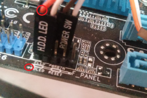
На вашей материнской плате все контакты подписаны и вы просто одеваете фишки на контакты соблюдая соответствующие названия и полярность. Полярность важна для HDD LED (IDE LED) и Power LED. На плате плюсовой контакт подписан как «+», а на фишке плюсовой контакт это цветной провод (отличный от белого и черного). Либо же если все провода от передней панели черного цвета, то на них «+» тоже будет подписан.
Полярность + и — при подключении PLED и HDLED
Даже если вы перепутаете полярность, то ничего страшного не произойдет. Просто на просто при включении не будет загораться кнопка включения и не будет моргать светодиод активности жесткого диска. В этом случае просто переверните не работающую фишку вверх ногами на контактах мат. платы, чтобы поменять полярность.
Вариант второй
Контакты на материнской плате не подписаны, как на фото ниже.
Контакты подключения передней панели на материнской плате без подписей
В этом случае вам нужно определить модель своей материнской платы, найти ее в интернете и посмотреть документацию по распиновке контактов кнопок, индикаторов, usb и звуковым выходам.
Инструкция со схемой подключения передней панели к материнской плате
Подключение передних аудио выходов и микрофона
особенности соблюдения полярности при подключении передней папнели
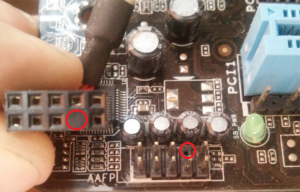
Подключение передних USB входов к материнской плате

Нет звука через HDMI: устройство уже используется другим приложением
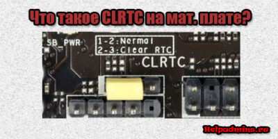
CLRTC на материнской плате asus что это?

jcom1 на материнской плате что это?
3 Комментариев
Александр
Сайт датирован 2018 годом, а фрагменты мам c разъёмами и др.элементами 10-летней давности ;-(
Передняя панель на корпусе системного блока никак не связана с остальными «внутренностями» компьютера. Значит, при ручном отключении с целью чистки или, что немного сложнее, при замене материнской платы, придётся самостоятельно подключать фронтальную панель. Далее будет в подробностях рассказано, как сделать это максимально правильно.
Этапы подключения передней панели к материнской плате
Рассмотрим основные моменты в подключении фронтальной панели к «материнке»:
Этап 1
Первым делом необходимо найти основной шлейф с 4 (иногда 5-6) штекерами. Возможна некоторая разница в названиях, цвете и т. д.
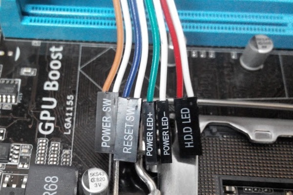
Расположенные на фото сверху штекеры подразумевают собой следующее:
- POWERSW (или PWRBTN) – активирует манипуляции с кнопкой включения/выключения компьютера на панели.
- H.D.D.LED (или HDLED) – лампочка, мигающая при работе жёсткого диска.
- POWERLED + и – (или PLED) – лампочка на кнопке включения/отключения компьютера; если компьютер работает, то горит, и наоборот; может быть цельным штекером.
- RESTARTSW (или RESET) – активирует кнопку перезагрузки компьютера.
- SPEAKER – небольшой динамик, издающий писк, если наблюдаются проблемы в работе компьютера.
Названия этих штекеров могут различаться, но не сильно. Например, вместо POWERSW может быть указано PW. А вместо RESTARTSW – просто RES. Сравнивая первые буквы названия штекеров и разъёмов, можно без труда понять, какой штекер куда должен подключаться. Также помогают цвета, которые, зачастую, соответствуют цвету кабелей от штекеров. Но в первую очередь нужно сравнивать именно названия, следом – цвета, ведь они могут различаться, в отличие от названий.
Этап 2
Вставлять штекеры необходимо в одно большое гнездо (FRONTPANEL или F_PANEL) на краю материнской платы. Обычно оно выглядит вот так:
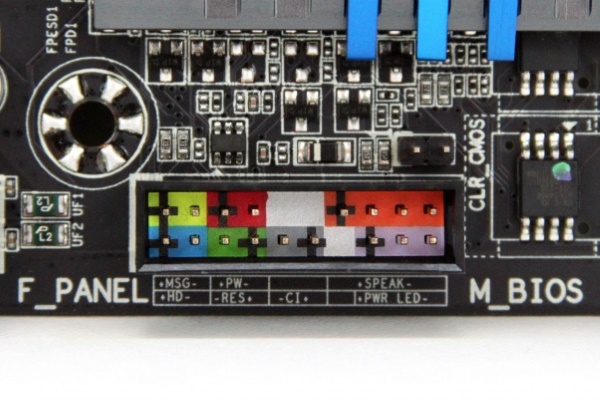
Чтобы подсоединить провода в разъёмы правильной стороной, можно просто посмотреть на сам штекер. Если в нём не будет хватать одного контакта (железная «спица»), то присоединять нужно этим местом, в соответствии с другим пустым местом на материнской плате, в разъёме. Также могут помочь боковые крепления на некоторых гнёздах и штекерах (крепления должны быть на одной стороне). Дополнительно можно ориентироваться по цветам в разъёме или визуальным подсказкам в виде блестящих контактов и т. п. Как правило, штекеры подсоединяются надписью «на себя» или в сторону надписей на материнской плате (схеме).
Внизу, под цветными разъёмами, схематично указаны (подписаны) места, куда нужно подключать штекеры. Например, согласно схеме под разъёмами, отвечающий за кнопку включения компьютера штекер (POWERSW) следует подсоединить в красное гнездо (второе слева, сверху, подписано как PW). Все остальные провода присоединяются в указанные на схеме места соответствующим образом.
В сопроводительной к компьютеру документации, если она имеется, также есть подсказки по подключению штекеров в гнёзда. Выглядят данные подсказки так:
Как видно на рисунке, в документах даже расшифровываются названия штекеров и сокращений на схеме. Например, RES – ResetSwitch (рус. «кнопка перезагрузки») и т. д.
Этап 3
Штекеры, отвечающие за работу USB-портов на передней панели, подключаются чуть иначе и проще. Выглядит USB-штекер — вот так:
Разъём для данного штекера может иметь следующие названия:
- F_USB1/F_USB2;
- USB1/USB2;
- или все гнёзда для этого штекера могут называться просто USB.
Не имеет значения, куда будет подключаться провод, так как все USB-гнёзда полностью идентичны. За исключением USB 3.0. Если на передней панели имеется именно такой USB-штекер, то и разъём на материнской плате нужно искать с соответствующим названием. Зачастую именно так он и называется – USB 3.0, но могут быть и исключения в виде F_USB30 и т. д.
Этап 4
Подключение звука (наушники/микрофон) на фронтальной панели происходит идентично описанным ранее процессам.
Берётся штекер из передней панели с названием AC97 или HDAUDIO и вставляется в разъём с соответствующей надписью:
Если звук так и не появился, возможно, проблема кроется в BIOS. Перезагрузив компьютер и «попав» в систему BIOS, следует проверить фронтальную панель и её характеристики. Иногда бывает, что подключён штекер HDAUDIO, а BIOS распознал подключённое устройство как AC 97. Решается данный недочёт изменением в BIOSе неправильного драйвера на соответствующий подключённому в материнской плате.
Видео-инструкция по подключению фронтальной панели к «материнке»
В следующем видео на наглядном примере и во всех деталях объясняется процесс присоединения штекеров в разъёмы на материнской плате.
Автор статьи: Шилин Алексей
Всем привет! В этой статье я наглядно покажу как правильно подключать кнопки (POWER, RESET) и устройства передней панели (F_PANEL, F_AUDIO и F_USB). Дело не хитрое, но стоит Вашего внимания.
В начале пару советов:
Разберу наглядно данное дело на старенькой материнской плате от фирмы Gigabyte модель GA-945GCM-S2C. Сразу скажу – Схемы подключения рисовал исключительно для данной статьи и на конкретном примере, цвета проводов у Вас будут отличаться. Главное понять и смысл подключения и воплотить (проверить) на своём ПК.

На этой картинке отображены разъёмы материнской платы для подключения коннекторов.
В основном (бывают исключения) под разъёмами мелким шрифтом написаны порядок подключения коннекторов и полярность. В моём случае указано:
PWR_LED (три разъемчика) – индикация включенного компьютера;
+PW- (PWRSW) – кнопка включения питания ПК;
-RES+ (RESET) – кнопка для перезагрузки ПК;
+HD- (IDE_LED, HDD_LED) – светодиод обращения к жесткому диску;
+SPEAK- (SPEAKER) – тот самый сигнал(ы), который издаёт компьютер при включении, если обнаружена ошибка.
Коннекторы выглядят так (см. скрины)

К каждому коннектрору подходят два провода:
В данном случае белые это минус «-» или Ground (земля) , а цветные «+». У коннектора SPEAKER (черный, красный) – чёрный «+», а красный «-«. Чтобы определить полярность коннекторов, достаточно его перевернуть на тыльную сторону – видим на против одного проводка маленький чёрный треугольник – это «+».
Переходим к следующему этапу, подключение передних дополнительных USB – разъёмов и картридера в разъёмы F_USB2 и F_USB1 (разницы нет, но лучше начинать по порядку). Если уже коннектор «спаянный», т.е. все проводки собраны в одну колодку – процесс значительно упрощается.
Просто подключаем этот «большой» коннектор состоящий из: восьми проводков, одного пустого и одного запаянного разъёма (всего десять) таким образом, чтобы ПУСТОЙ разъемчик совпал с ЗАПАЯННЫМ гнездом в коннекторе. (см. скрины)

А, вот если у Вас пучок проводов как на картинке – нарисую наглядную схемку:)

Здесь мы видим: POWER (Питание – 2 шт.), GND (Ground – «земля» 2шт.), D3+ (плюс), D3- (минус) на один порт usb и D2+ (плюс), D2- (минус) на другой порт. Как Вы уже догадались, два коннектора POWER идентичны и их можно менять местами между собой, так же как и GND. Главное не перепутать местами POWER и GND.

Так теперь осталось разобраться с подключением F_AUDIO разъемов для микрофона и наушников.
Опять же, если Вам повезло и от передней панели идёт большая колодка с 10-ью гнездами, просто вставляем (тут точно не ошибетесь). У меня случай поинтереснее. ) А, именно такие коннекторы: SPK R (выход правого канала на переднюю панель), SPK L (выход левого канала на переднюю панель), MIC (выход микрофона на переднюю панель) и GND.


Вот и всё подключено. Спасибо за внимание, удачи.
Если у Вас отличаются провода, названия коннекторов (колодок) и тд. и тп. не ленитесь, скачайте с официального сайта производителя Вашей материнской платы мануал (руководство) и там 99% найдёте схемы подключения всех F_PANEL, F_AUDIO и F_USB.
Черный экран windows 7 – Узнайте как избавиться от черного экрана Windows 7.
Восстановление windows 7 – Как произвести восстановление системы Windows 7.
Как активировать windows 7 – Как легально активировать windows 7.
Источник