- Manuals
- Brands
- Mitsubishi Electric Manuals
- DC Drives
- FR-D740 SC EC
Manuals and User Guides for Mitsubishi Electric FR-D740 SC EC. We have 1 Mitsubishi Electric FR-D740 SC EC manual available for free PDF download: Instruction Manual
Mitsubishi Electric FR-D740 SC EC Instruction Manual (512 pages)
FR-D700 Series
Brand: Mitsubishi Electric
|
Category: DC Drives
|
Size: 14.14 MB
Table of Contents
-
Table of Contents
13
-
Inverter Type
21
-
Description of the Case
22
-
Accessory
23
-
-
Removal and Reinstallation of the Front Cover
25
-
FR-D740-120SC and FR-D740-160SC
26
-
-
Removal and Reinstallation of the Wiring Cover
28
-
Mounting
29
-
Enclosure Design
31
-
Inverter Placement
35
-
-
Inverter and Peripheral Devices
37
-
Peripheral Devices
39
-
-
Terminal Connection Diagram
40
-
Main Circuit Connection
42
-
Control Circuit Specifications
49
-
Control Circuit Terminals
53
-
Wiring Instructions
57
-
Safety Stop Function
58
-
Changing the Control Logic
63
-
PU Connector
66
-
RS485 Communication
67
-
-
Connection of Stand-Alone Option Units
68
-
Connection of a Brake Unit FR-BU2
73
-
Connection of the High Power Factor Converter FR-HC
76
-
Connection of the Power Regeneration Common Converter FR-CV
77
-
Connection of the Power Improving DC Reactor FFR-HEL-(H)-E
78
-
Installation of a Reactor
79
-
-
Electromagnetic Compatibility (EMC)
80
-
Inverter-Generated Noises and Their Reduction Techniques
84
-
Power Supply Harmonics
87
-
Inverter-Driven 400V Class Motor
88
-
-
Precautions for Use of the Inverter
89
-
Failsafe of the System Which Uses the Inverter
92
-
-
Drive the Motor
95
-
Operation Panel
96
-
Basic Operation (Factory Setting)
98
-
Easy Operation Mode Setting (Easy Setting Mode)
99
-
Operation Lock
101
-
Monitoring of Output Current and Output Voltage
103
-
Change the Parameter Setting Value
104
-
Parameter Clear/All Parameter Clear
105
-
Initial Value Change List
106
-
-
Simple Mode Parameter List
109
-
Overheat Protection of the Motor by the Inverter
110
-
When the Rated Motor Frequency Is 60Hz (Pr. 3)
112
-
Increase the Starting Torque (Pr. 0)
113
-
Limit the Maximum and Minimum Output Frequency (Pr. 1, Pr. 2)
115
-
Change the Acceleration/Deceleration Time (Pr. 7, Pr.

117
-
Operation Mode Selection (Pr. 79)
119
-
-
PU Operation Mode
129
-
Set the Set Frequency to Operate
130
-
Use the Digital Dial Like a Potentiometer to Perform Operation
132
-
Use Switches to Give the Frequency Command (Multi-Speed Setting)
133
-
Perform Frequency Setting by Analog Voltage Input
135
-
Perform Frequency Setting by Analog Current Input
137
-
-
External Operation
139
-
Multi-Speed Setting) (Pr. 4 to Pr. 6)
141
-
Perform Frequency Setting by Analog Voltage Input
144
-
Of Potentiometer (at 5V)
147
-
-
Perform Frequency Setting by Analog Current Input
148
-
Of Potentiometer (at 20Ma)
150
-
-
-
Parameter Overview
151
-
Adjust the Output Torque (Current) of the Motor
176
-
Slip Compensation (Pr. 245 to Pr. 247)
182
-
-
Limit the Output Frequency
190
-
Set V/F Pattern
194
-
Load Pattern Selection (Pr. 14)
196
-
-
Frequency Setting by External Terminals
198
-
Jog Operation (Pr. 15, Pr. 16)
201
-
Remote Setting Function (Pr. 59)
205
-
-
Acceleration and Deceleration
209
-
Starting Frequency and Start-Time Hold Function
212
-
Acceleration and Deceleration Pattern (Pr. 29)
214
-
-
Selection and Protection of a Motor
216
-
Applied Motor (Pr. 71, Pr. 450)
222
-
-
Motor Brake and Stop Operation
231
-
Selection of a Regenerative Brake (Pr. 30, Pr. 70)
234
-
Stop Selection (Pr. 250)
236
-
-
Function Assignment of External Terminals
238
-
Inverter Output Shutoff Signal (MRS Signal, Pr. 17)
241
-
Selection Signal (RT, Pr. 155)
243
-
-
Start Signal Selection (Terminal STF, STR, STOP, Pr. 250)
244
-
Output Terminal Function Selection (Pr. 190, Pr. 192, Pr. 197)
248
-
Detection of Output Frequency (SU, FU, Pr. 41 to Pr. 43)
253
-
Remote Output Function (REM, Pr. 495, Pr. 496)
257
-
-
Monitor Display and Monitor Output Signals
259
-
Monitor Display Selection of DU/PU and Terminal am (Pr. 52 Pr. 158, Pr. 170, Pr. 171, Pr. 268, Pr. 563, Pr. 564, Pr. 891)
261
-
Terminal am Calibration [C1 (Pr.901)]
270
-
Power Failure-Time Deceleration-To-Stop Function (Pr. 261)
284
-
-
Operation Setting at Alarm Occurrence
288
-
Input/Output Phase Failure Protection Selection (Pr. 251, Pr. 872)
291
-
Earth (Ground) Fault Detection at Start (Pr. 249)
292
-
-
Energy Saving Operation
293
-
Motor Noise, EMI Measures, Mechanical Resonance
294
-
Speed Smoothing Control (Pr. 653)
296
-
-
Frequency Setting by Analog Input (Terminal 2, 4)
297
-
Input Filter Time Constant (Pr. 74)
302
-
Pr. 125, Pr. 126, Pr. 241, C2 (Pr. 902) to C7 (Pr. 905)]
303
-
-
-
Misoperation Prevention and Parameter Setting Restriction
310
-
Parameter Write Selection (Pr. 77)
315
-
Reverse Rotation Prevention Selection (Pr. 78)
317
-
Extended Parameter Display (Pr. 160)
318
-
Password Function (Pr. 296, Pr. 297)
319
-
-
Selection of Operation Mode and Operation Location
322
-
Operation Mode at Power on (Pr. 79, Pr. 340)
334
-
Start Command Source and Frequency Command Source During Communication Operation (Pr. 338, Pr. 339, Pr. 551)
336
-
-
Communication Operation and Settings
343
-
Communication E²PROM Write Selection (Pr. 342)
354
-
Mitsubishi Inverter Protocol (Computer Link Communication)
355
-
-
Special Operation
392
-
Dancer Control (Pr. 44, Pr. 45, Pr. 128 to Pr. 134)
405
-
Traverse Function (Pr. 592 to Pr. 597)
414
-
-
Useful Functions
420
-
Display of the Life of the Inverter Parts (Pr. 255 to Pr. 259)
421
-
Maintenance Timer Alarm (Pr. 503, Pr. 504)
426
-
Current Average Value Monitor Signal (Pr. 555 to Pr. 557)
427
-
Free Parameters (Pr. 888, Pr. 889)
431
-
-
Setting for the Parameter Unit and Operation Panel
432
-
Magnitude of Frequency Change Setting (Pr. 295)
434
-
Buzzer Control (Pr. 990)
435
-
-
List of Alarm Display
438
-
Causes and Corrective Actions
440
-
Reset Method of Protective Function
453
-
LED Display
454
-
Check and Clear of the Fault History
455
-
Check First When You Have Troubles
457
-
Motor or Machine Generates Abnormal Noise
459
-
Motor Generates Heat Abnormally
460
-
Acceleration/Deceleration Is Not Smooth
461
-
Speed Varies During Operation
462
-
Operation Mode Is Not Changed Properly
463
-
Motor Current Is too Large
464
-
Speed Does Not Accelerate
465
-
Unable to Write Parameter Setting
466
-
-
Meters and Measuring Methods
467
-
Measurement of Powers
468
-
Measurement of Voltages and Use of PT
469
-
Use of CT and Transducer
470
-
-
Inspection
471
-
Daily and Periodic Inspection
472
-
Display of the Life of the Inverter Parts
474
-
Checking the Inverter and Converter Modules
475
-
Cleaning
476
-
-
Measurements on the Main Circuit
480
-
Measurement of Voltages and Currents
481
-
A.1 Specifications
485
-
A Appendix
486
-
-
Phase, 400V Class
486
-
A.2 Common Specifications
487
-
A.3 Outline Dimension Drawings
489
-
A.3.2 FR-D720S-070SC and FR-D740-012SC to 080SC
490
-
A.3.3 Fr-D720S-100Sc
491
-
A.3.4 FR-D740-120SC and 160SC
492
-
A.3.5 Parameter Unit FR-PU07
493
-
A.3.6 Parameter Unit FR-PA07
494
-
A.4 Parameter List with Instruction Codes
495
-
A.5 Specification Change
503
-
-

Advertisement
Advertisement
Related Products
-
Mitsubishi Electric FR-D740-0.4K-G
-
Mitsubishi Electric FR-D740-0.75K-G
-
Mitsubishi Electric FR-D740-1.5K-G
-
Mitsubishi Electric FR-D740-2.2K-G
-
Mitsubishi Electric FR-D740-3.7K-G
-
Mitsubishi Electric FR-D720-0.2K-G
-
Mitsubishi Electric FR-D720-1.5K-G
-
Mitsubishi Electric FR-D720-3.7K-G
-
Mitsubishi Electric FR-D720S SC EC
-
Mitsubishi Electric FR-D740-15K
Mitsubishi Electric Categories
![]()
Air Conditioner
Controller
![]()
Projector
Inverter
Heat Pump
More Mitsubishi Electric Manuals
Серия преобразователей частоты FR-D700 отличается простотой эксплуатации, надежностью и компактными габаритами. Имеют упрощенный электромонтаж благодаря использованию пружинных клемм, встроенный пульт управления с принципиально новой идеологией доступа к параметрам, увеличенный момент в области низких частот вращения, встроенную функцию аварийного отключения и функцию безопасного останова. Основные области применения: насосы, вентиляторы, прессы, конвейеры, промышленные стиральные машины, автоматизированные стеллажные системы и др.
Отличительные особенности:
- Бессенсорное векторное управление
- Высокий вращающий момент на низких частотах вращения
- Функция автоматической настройки параметров
- Функция автоматического рестарта после пропадания питающего напряжения с определением частоты и подхватом свободно вращающегося двигателя
- Интерфейс RS-485, поддерживается протокол Modbus RTU
- Возможность монтажа в шкафу управления вплотную в ряд, без зазоров
- Пульт управления, встроенный в инвертор
- Возможность подключения дополнительных выносных пультов, которые могут быть установлены на удаленной до 15м от ПЧ управляющей панели
- Встроенный тормозной транзистор (от 0,1 кВт до 7,5 кВт)
- Специальные функции встроенной самодиагностики, позволяющие оценить степень износа основных компонентов во время эксплуатации и заранее проинформировать пользователя о необходимости их замены
- Управляемое торможение при кратковременных сбоях в питающей сети
- Функция экономии энергии с применением оптимального возбуждения магнитного потока в двигателе
- Расширенная функция ПИД-регулирования
Дополнительная информация:
 Спецификация FR-D740-050SC-EC скачать. pdf
Инструкция FR-D740-050SC-EC скачать. pdf
Запросить дополнительную информацию и цены
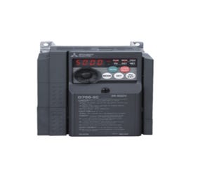
Inverter; Rated Power: 2,2kW; 3×380-480V; Rated Current: 5A@50°C; IP20
- TECHNICAL INFORMATION
- ADDITIONAL INFORMATION
- ENVIRONMENTAL
- Загрузки
FA-Inverter: Inverter
| Series | FR-D700 SERIES |
|---|---|
| Type | FR-D700 COMPACT INVERTER |
| Minimum Rated Voltage (V) | 380 |
| Min. Permissible Voltage (V) | 325 |
| Maximum Rated Voltage (V) | 480 |
| Max. Permissible Voltage (V) | 528 |
| Current Type | AC |
| Phases | 3 |
| Rated Output Current ND (A) | 5 |
| Rated Motor Capacity ND (kW) | 2,2 |
| Control Method | V/F CONTROL, SOFT-PWM/HIGH FREQUENCY PWM , MAGNETIC FLUX VECTOR CONTROL |
| Motor Type | INDUCTION MOTOR |
| Brake Chopper ED (%) | 30 |
| Integrated EMC Filter | NO |
| Safe Torque Off (STO) | YES |
| Regenerative (4Q) | NO |
| Display | BUILT-IN |
| PLC Function | NO |
| Integrated Analogue Outputs | 1 |
| RS-485 | 1 |
| Power Loss ND (W) | 100 |
| Frequency Range (Hz) | 0,2–400 |
| Integrated DC Choke | NO |
| Display Type | 4 DIGITS LED |
| Integrated Digital Inputs | 5 |
| Digital Outputs (Transistor) | 1 |
| Digital Outputs (Relay) | 1 |
| Integrated Analogue Inputs | 2 |
| IO Type of Terminal Block | SPRING CLAMP |
| Expandable | NO |
| USB | NO |
| Ethernet Port | NO |
| Built-In Network | MODBUS-RTU |
| Leakage Current (mA) | 1 |
| Standby Power Consumption (W) | 10,5-17 |
| Protection Class | IP20 |
Product Dimensions & Weight
| Width (mm) | 108 |
|---|---|
| Height (mm) | 128 |
| Depth (mm) | 155,5 |
| Weight (kg) | 1,4 |
Conformity
| CE | COMPLIANT |
|---|---|
| UL/cUL | COMPLIANT |
| EAC | COMPLIANT |
| UKCA | COMPLIANT |