-
Contents
-
Table of Contents
-
Bookmarks
Quick Links
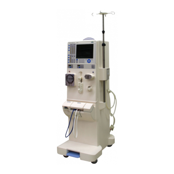
4008 S
Hemodialysis device
Service Manual
Software version: 11.40 and higher
Edition: 7/01.13
Part no.: M49 985 1
0123
Related Manuals for Fresenius Medical Care 4008 S
Summary of Contents for Fresenius Medical Care 4008 S
-
Page 1
4008 S Hemodialysis device Service Manual Software version: 11.40 and higher Edition: 7/01.13 Part no.: M49 985 1 0123… -
Page 3: Table Of Contents
Supply mains ……………………..4-5 Guidance and manufacturer’s declaration for EMC (IEC 60601-1-2)……………………… 4-8 4.8.1 Electromagnetic emissions………………….4-8 4.8.2 Electromagnetic immunity ………………….4-8 4.8.3 Recommended separation distances between portable and mobile RF Fresenius Medical Care 4008 S (Version V10) SM-EN 7/01.13…
-
Page 4
Setting the digital outputs of CPU 1 …………….5-48 5.1.4.10 Setting the digital outputs of CPU 2 …………….5-54 5.1.4.11 Setting / reading the digital outputs of CPU 1 …………5-57 Fresenius Medical Care 4008 S (Version V10) SM-EN 7/01.13… -
Page 5
Positive pressure test (positive pressure holding test) ………….. 7-11 7.1.14 UF function test ……………………. 7-14 7.1.15 Conductivity test ……………………7-15 7.1.16 DIASAFE plus test/ HPU test ………………..7-16 Device error during cleaning programs …………….7-18 Fresenius Medical Care 4008 S (Version V10) SM-EN 7/01.13… -
Page 6
Part 12.3: Calibrating the concentrate pump stroke …………..9-22 9.1.27 Part 12.4: Measuring the volume of the concentrate pump in liters……….. 9-23 9.1.28 Part 12.5: Calibrating the bicarbonate pump stroke …………..9-24 Fresenius Medical Care 4008 S (Version V10) SM-EN 7/01.13… -
Page 7
Assignment of the hydraulic processing unit (HPU) …………..10-9 10.4 Assembly of components………………… 10-10 10.4.1 Self-cutting screws ……………………10-10 10.4.2 Torques ……………………… 10-10 10.5 Housing and cart ……………………10-11 10.5.1 Tilting the device……………………10-11 Fresenius Medical Care 4008 S (Version V10) SM-EN 7/01.13… -
Page 8
10.8.16 Filter holder for DIASAFE plus ………………..10-41 10.9 Extracorporeal Blood Circuit Module (EBM)…………… 10-42 10.9.1 Opening and closing the EBM, service position …………..10-42 10.9.2 Pneumatic unit contamination………………..10-43 10.9.3 BPM (option)……………………..10-44 viii Fresenius Medical Care 4008 S (Version V10) SM-EN 7/01.13… -
Page 9
HPU wiring diagram (hydraulic processing unit)…………..11-47 11.2.6 CAN communication connection diagram …………….11-49 11.2.7 P.C.B. LP 450-2 Air detector control (LD) …………….11-50 11.2.8 P.C.B. LP 493 Blood leak detector ………………11-52 Fresenius Medical Care 4008 S (Version V10) SM-EN 7/01.13… -
Page 10
11.2.24 P.C.B. LP 1629 EBM display ………………..11-71 11.2.25 P.C.B. LP 1631 CPU 1 ………………….11-72 11.2.26 Heater board (4008 power supply unit) ………………. 11-74 11.2.27 Power board (4008 power supply unit) ………………11-75 12 Appendix Fresenius Medical Care 4008 S (Version V10) SM-EN 7/01.13… -
Page 11
Error messages 7-1 Hydraulic unit, description 11-30 CALIBRATION menu structure 9-2 Error messages after turning Hydraulics unit 9-42 power on 7-28 CAN communication connection diagram 11-49 Error messages during dialysis 7-29 Fresenius Medical Care 4008 S (Version V10) SM-EN 7/01.13… -
Page 12
Tools (service equipment) 8-1 P.C.B. LP 632: DIP switch (array 2) 5-69 Traffic light (operation status indicator) 10-22 P.C.B. LP 634: DIP switch (array 1) 5-70 Transportation of hemodialysis unit 3-28 Fresenius Medical Care 4008 S (Version V10) SM-EN 7/01.13… -
Page 13
– Edition, e.g., 4/03.11 means, 4th edition, March 2011 – The page identification 1-3, for example refers, to chapter 1, page 3. Organization of the To facilitate the use of documents from Fresenius Medical Care, the chapters organization of the chapters has been standardized in all manuals. -
Page 14: Significance Of The Note
A T1 test and a check of the electrical safety must be performed after working on the device working on the device. The current Operating Instructions must be enclosed with the device. If necessary, additional operator training is required. Fresenius Medical Care 4008 S (Version V10) SM-EN 7/01.13…
-
Page 15: Technical Documentation
Touching live parts will cause an electric shock. Disconnect the power plug before opening the device. Actuating the On / Off switch stops operation of the device, but does not disconnect the device from the supply voltage! Fresenius Medical Care 4008 S (Version V10) SM-EN 7/01.13…
-
Page 16: Addresses
Phone: +49 6172 609-0 www.fmc-ag.com International Fresenius Medical Care service Deutschland GmbH Service Support International Hafenstrasse 9 97424 Schweinfurt Germany Phone: +49 9721 678-333 (hotline) Fax: +49 9721 678-130 Local service Fresenius Medical Care 4008 S (Version V10) SM-EN 7/01.13…
-
Page 17: Installation
ESD precautions When repairing the device and when replacing spare parts, observe the applicable ESD precautions. TSC/ MA intervals The TSC/MA procedures on this device are to be performed after 24 months. Fresenius Medical Care 4008 S (Version V10) SM-EN 7/01.13…
-
Page 18: Important Information For Use In A Domestic Environment
Moving within a domestic (see Transportation of hemodialysis unit page 3-28) environment Initial start-up report See the following pages. Fresenius Medical Care 4008 S (Version V10) SM-EN 7/01.13…
-
Page 19
Arterial zero point: 0 mmHg (±10 mmHg) CALIBRATION Yes No Venous zero point: 0 mmHg (±10 mmHg) CALIBRATION Yes No Check of the blood leak detector Fresenius Medical Care 4008 S (Version V10) SM-EN 7/01.13… -
Page 20
Run the disinfection program. Cleaning / – – disinfection 14.4 Operating Instructions and accessories package complete and match the – – device. 14.5 Attach TSC inspection label. – – Fresenius Medical Care 4008 S (Version V10) SM-EN 7/01.13… -
Page 21
The device has been released for further use Yes (attach inspection label). No Date of next inspection: Remarks: Date: Signature: Stamp: Warning On completion of these procedures it is imperative to run a disinfection. Fresenius Medical Care 4008 S (Version V10) SM-EN 7/01.13… -
Page 22: Explanations For The Initial Start-Up Report
Re 1.2 The following closing plugs have to be removed: – on the overflow tube of the heater block – on the disinfectant connector – on the water inlet plate Fresenius Medical Care 4008 S (Version V10) SM-EN 7/01.13…
-
Page 23
Re 2.1 Labels and identifications are present and legible (with illustrations below). 2 x label «Type label complete device“ Check device specification: Serial number Equipment code 1 x label «Made in Germany» Fresenius Medical Care 4008 S (Version V10) SM-EN 7/01.13… -
Page 24
(monitor / chassis unit) 1 x label «Type label monitor unit / chassis unit“ 1 x label «Hot surface“ 1 x label «Power supply unit type label“ 1 x label «Hydraulic unit type label“ Fresenius Medical Care 4008 S (Version V10) SM-EN 7/01.13… -
Page 25
Chapter 3: Installation 1 x label «Type label EBM“ 1 x label «Insert dialyzer lines here“ 1 x label «Refer to instruction manual/booklet“ Fresenius Medical Care 4008 S (Version V10) SM-EN 7/01.13… -
Page 26
Chapter 3: Installation ® 1 x label „Hot rinse“ (DIASAFE plus) 1 x label „Hot rinse“ (overflow tube) 1 x label „Hot rinse“ (shunt interlock) 1 x label „Hot rinse“ (disinfection solution) 3-10 Fresenius Medical Care 4008 S (Version V10) SM-EN 7/01.13… -
Page 27
Chapter 3: Installation 1 x label „Potential equalization“ 1 x label «To / from dialyser“ 1 x label «CDS warning label“ (option) 1 x label «Water input / drain, max. 6 bar“ Fresenius Medical Care 4008 S (Version V10) SM-EN 7/01.13 3-11… -
Page 28
1 x label „max. 5 kg“ (IV pole) ® 1 x label „Hot rinse“ (bibag connector, on the outside) ® ® 1 x label „bibag “ (bibag connector, on the inside) 3-12 Fresenius Medical Care 4008 S (Version V10) SM-EN 7/01.13… -
Page 29
1 x label „Hot rinse“ (sealing cap, on the outside) 2 x Label «Warning label risk of hand injury» (EBM hinge bracket on the left and on the right) 1 x label „Warning“ (BPM connection) Fresenius Medical Care 4008 S (Version V10) SM-EN 7/01.13 3-13… -
Page 30
Chapter 3: Installation 2 x labels «Tipping hazard» (housing left and housing right) Bed-Side-Link (option): 2 x label: „LAN“ and „CardBox“ 3-14 Fresenius Medical Care 4008 S (Version V10) SM-EN 7/01.13… -
Page 31
To be checked: – Tubings and cuff of BPM (option) Re 2.3 The power cable shows no signs of damage. Re 2.4 Blood pump emergency crank attached to housing rear. Fresenius Medical Care 4008 S (Version V10) SM-EN 7/01.13 3-15… -
Page 32
(switch 3, 4, 5 to OFF and switch 7 depending on the heater rod) LP1631 – Without Central Delivery System: P.C.B. LP 1631: Array 2, switch 7 on ON LP1631 3-16 Fresenius Medical Care 4008 S (Version V10) SM-EN 7/01.13… -
Page 33
Rinse to remove any preservatives. Operating condition: Cleaning / rinsing – Turn the hemodialysis device on – Wait until the device is completely booted up. Then set the service switch (1) to ON (top). Fresenius Medical Care 4008 S (Version V10) SM-EN 7/01.13 3-17… -
Page 34
Operating condition: Service mode / CALIBRATION Re 5 Check of the zero point of the pressure display (art./ven.) Re 5.1 Arterial zero point: 0 mmHg (±10 mmHg) Operating condition: Service mode / CALIBRATION 3-18 Fresenius Medical Care 4008 S (Version V10) SM-EN 7/01.13… -
Page 35
10 cm above the shunt interlock. CAL. DIAL. PRESSURE Conf Conf DIALYSATE Pressure see Part 14.1 Conf TMP-Check see Part 14.2 Conf PDIAL2 press-check see Part 14.3 Conf back to menu ? Fresenius Medical Care 4008 S (Version V10) SM-EN 7/01.13 3-19… -
Page 36
Operating condition: Service mode / CALIBRATION Re 9 Check of the extracorporeal components Re 9.1 Blood pumps: Check the blood pump rate. (see chapter 9.1.8 page 9-9). Operating condition: Service mode / CALIBRATION 3-20 Fresenius Medical Care 4008 S (Version V10) SM-EN 7/01.13… -
Page 37
The exact measuring points are indicated in the figures. – Heater rod — outward measurement point (screw head) (1) on the bottom right on the rear side of the device Fresenius Medical Care 4008 S (Version V10) SM-EN 7/01.13 3-21… -
Page 38
Chapter 3: Installation – Screw head (2) / monitor rear – Screw head (3) / power supply unit 3-22 Fresenius Medical Care 4008 S (Version V10) SM-EN 7/01.13… -
Page 39
Differential current measurement according to figure 5: Direct measurement according to fig. 4 The unit under test must be insulated when installed. All earth connections (e.g. potential equalization, …) have to be removed. Fresenius Medical Care 4008 S (Version V10) SM-EN 7/01.13 3-23… -
Page 40
Last measured value: 390 µA 470 + (470 – 390) = 470 + 80 = 550 (-> not passed!) Re 11 Functional test Re 11.1 T1 test performed. Operating condition: T1 Test 3-24 Fresenius Medical Care 4008 S (Version V10) SM-EN 7/01.13… -
Page 41
– Use the syringe to generate a pressure of approx. 2 bar (see Checking the venous occlusion clamp page 9-51). – The pressure may not drop by more than 0.1 bar within 3 minutes. Fresenius Medical Care 4008 S (Version V10) SM-EN 7/01.13 3-25… -
Page 42
Check the desired temperature of 36.5 °C (±0.2 °C) using a reference measuring instrument connected between the dialyzer couplings. – Optical detector = dark (NTC 109 is active) – Flow = 500 ml/min 3-26 Fresenius Medical Care 4008 S (Version V10) SM-EN 7/01.13… -
Page 43
Date of next inspection: The next inspection date has to be entered in the report. The intervals prescribed by the manufacturer must be observed. Fresenius Medical Care 4008 S (Version V10) SM-EN 7/01.13 3-27… -
Page 44: Transportation Of Hemodialysis Unit
Risk of tilting when pushing the device or leaning against it If lateral force is exerted it may result in tilting or slipping of the device. Check transportation conditions are as stated. 3-28 Fresenius Medical Care 4008 S (Version V10) SM-EN 7/01.13…
-
Page 45
After transportation – After moving the device, bring the hemodialysis device back into service (see Restarting after removing 4008 from Service). Fresenius Medical Care 4008 S (Version V10) SM-EN 7/01.13 3-29… -
Page 46
Chapter 3: Installation 3-30 Fresenius Medical Care 4008 S (Version V10) SM-EN 7/01.13… -
Page 47: Specifications
Empty weight incl. all options: approx. 86 kg Safe working load: approx. 39 kg Maximum total weight: approx. 125 kg (Empty weight incl. all options + safe working load = maximum total weight) Fresenius Medical Care 4008 S (Version V10) SM-EN 7/01.13…
-
Page 48: Type Label (Identification Of The Device)
Manufacturer with date of manufacture as year digit Operating temperature range Power requirements (voltage / power consumption) Maximum total weight (empty weight + safe working load) Serial number Type identification Equipment code (EC) Fresenius Medical Care 4008 S (Version V10) SM-EN 7/01.13…
-
Page 49: Operating Environment
Degree of protection Defibrillator-protected applied part of type CF against electric shock (blood pressure cuff) Degree of protection drip-proof against ingress of liquids Leakage currents according to IEC 60601-1 Fresenius Medical Care 4008 S (Version V10) SM-EN 7/01.13…
-
Page 50: Electrical Supply
1 x T 3.15 A; power supply unit, fuse in housing foot (rear) / SI5 Power board T 3.15 A Safety fuse Axial FF 10 A Safety fuse Heater board T 2.5 A Safety fuse T 6.3 A Safety fuse T 16 A Safety fuse Fresenius Medical Care 4008 S (Version V10) SM-EN 7/01.13…
-
Page 51: Supply Mains
Recommendation: one residual-current device for each device (or outlet) (RCD less than or equal to 30 mA). – Overvoltage / lightning protection in the main and emergency power supply. Fresenius Medical Care 4008 S (Version V10) SM-EN 7/01.13…
-
Page 52
(B / BF / CF) Housing leakage currents of all types 10 times higher than ”CF” Via the blood and patient leakage current! the dialysate, the patient is electrically connected to the earth potential. Fresenius Medical Care 4008 S (Version V10) SM-EN 7/01.13… -
Page 53
Additionally, the room must comprise a potential equalization. For further information see IEC 60364-7-710. Fresenius Medical Care 4008 S (Version V10) SM-EN 7/01.13… -
Page 54: Guidance And Manufacturer’s Declaration For Emc (Iec 60601-1-2)
±1 kV differential ±1 kV differential Mains power quality should be that of a IEC 61000-4-5 mode mode typical commercial and / or hospital ±2 kV common mode ±2 kV common mode environment. Fresenius Medical Care 4008 S (Version V10) SM-EN 7/01.13…
-
Page 55
Interference may occur in the vicinity of equipment marked with the following symbol. Fresenius Medical Care 4008 S (Version V10) SM-EN 7/01.13… -
Page 56: Recommended Separation Distances Between Portable And Mobile Rf
(W) according to the transmitter manufacturer. Note: These guidelines may not apply in all situations. Electromagnetic propagation is affected by absorption and reflection from structures, objects and people. 4-10 Fresenius Medical Care 4008 S (Version V10) SM-EN 7/01.13…
-
Page 57: Operating Conditions
*AL = Action Level. ISO 13959:2009: Concentration from which on steps should be taken to interrupt the trend towards higher, unacceptable values. The value usually is about 50% of the alarm limit. Fresenius Medical Care 4008 S (Version V10) SM-EN 7/01.13 4-11…
-
Page 58: Consumption Data / Energy Data
Other data is available from the manufacturer on request. Average water Dialysis: approx. 30 liters consumption Disinfection: approx. 14.5 liters Heat disinfection: approx. 10.5 liters Mean acid concentrate Dialysis (mixing ratio 1+44 ACF): approx. 0.7 liters consumption 4-12 Fresenius Medical Care 4008 S (Version V10) SM-EN 7/01.13…
-
Page 59: Storage Conditions
IEC or ISO standards (e.g., IEC 60950-1 for information technology equipment). Furthermore, all device configurations shall comply with the requirements for medical electrical systems (see Chapter 16 and Appendix I to EN 60601-1:2006). Fresenius Medical Care 4008 S (Version V10) SM-EN 7/01.13 4-13…
-
Page 60: Override Conditions
Mute alarm time: adjustable in the SETUP MENU from 1 minute to 2 minutes (factory setting: 1 minute) Any new alarm reactivates the silenced audible alarm. Blood leak override Override time: 2 minutes 4-14 Fresenius Medical Care 4008 S (Version V10) SM-EN 7/01.13…
-
Page 61: Materials Used
4.14 Materials used Plastics Description Use in the dialysis circuit EPDM PA (PA 6.6) PBT / ABS GF 20 PC+ABS PE (soft) PEEK Polyester PP-H PP(E) PPSU Fresenius Medical Care 4008 S (Version V10) SM-EN 7/01.13 4-15…
-
Page 62
CM/ EPDM-L EPDM Metals / glass Description Use in the dialysis circuit Graphite Glass Aluminum Sheet copper Steel sheet Aluminum sheet St37K 1.4300 1.4301 1.4305 1.4401 1.4404 / 1.4435 4-16 Fresenius Medical Care 4008 S (Version V10) SM-EN 7/01.13… -
Page 63
Synchroflex (toothed belt) Sirex PU foam (insulating boards), open-pored, adhesive on one side Ceramics Miscellaneous – adhesives Description Use in the dialysis circuit Loctite Scotch-Weld DP 460 Scotch-Weld V 23 Fresenius Medical Care 4008 S (Version V10) SM-EN 7/01.13 4-17… -
Page 64
Dilution: Type FS 225 Screening lacquer: Elektro DAG 438/ Fa. Acheson Screwlock Loctite 243 Miscellaneous – packaging Description Use in the dialysis circuit Ethafoam (polystyrene) Corrugated cardboard Cellular rubber Wooden pallet 4-18 Fresenius Medical Care 4008 S (Version V10) SM-EN 7/01.13… -
Page 65
Potting compound PU 151/20, UP resin, Iron core Copper + tin, Plug connectors glassfiber enforced thermoplast P.C.B. base material, epoxy fiberglass Electronic components Ferrite cores, lithium batteries, lead-acid battery Copper, PVC, Teflon Cables Fresenius Medical Care 4008 S (Version V10) SM-EN 7/01.13 4-19… -
Page 66
Chapter 4: Specifications 4-20 Fresenius Medical Care 4008 S (Version V10) SM-EN 7/01.13… -
Page 67: Setup / Service Program
Setting the service switch to ON while the treatment or the cleaning program is in progress will turn off the heater relay. 5.1.1 Service mode overview CALIBRATION DIAGNOSTICS MISCELLANEOUS SETUP MENU Fresenius Medical Care 4008 S (Version V10) SM-EN 7/01.13…
-
Page 68: Service Mode Key Functions
Scrolling through menu items / Selecting a menu item Conf Changing values and functions in the menus + / – Storing the modified values (Audio paused) Exiting a menu without saving the data Fresenius Medical Care 4008 S (Version V10) SM-EN 7/01.13…
-
Page 69: Setup Menu
SET BPM see Part 22 Conf Conf UF EINSTELLUNGEN see Part 11 STORE DEFAULT VALUES see Part 23 Conf Conf SET STD. PRIME-TIME see Part 12 BACK TO MAIN MENU ? Fresenius Medical Care 4008 S (Version V10) SM-EN 7/01.13…
-
Page 70: Part 1: Setting Alarm And Warning Times
Set ART-AL DELAYTIME Conf Art Al Delay = 5s Set the desired delay time (0 to 5 seconds) by pressing the +/– keys. Audio paused DATA STORED After approx. 3 seconds Fresenius Medical Care 4008 S (Version V10) SM-EN 7/01.13…
-
Page 71
Part 1.4: Setting the UF warning time Set UF-WARNING-TIME Conf UF-Warn-Time = 10min Set the desired warning time (10, 30 min) by pressing the +/– keys. Audio paused DATA STORED After approx. 3 seconds Fresenius Medical Care 4008 S (Version V10) SM-EN 7/01.13… -
Page 72: Part 2: Setting The Cleaning Program
3 seconds 5.1.3.3 Part 2: Setting the cleaning program SETUP CLEANING PGM Conf Conf CLEANING Times see Part 2.1 Conf DEFAULT Cleaning Pgm see Part 2.2 Conf back to menu ? Fresenius Medical Care 4008 S (Version V10) SM-EN 7/01.13…
-
Page 73
Part 2.1.1: Rinsing time Rinsing TIME Conf Rinsing Time = 15min Set the desired time (5 to 30 min) by pressing the +/– keys. Audio paused DATA STORED After approx. 3 seconds Fresenius Medical Care 4008 S (Version V10) SM-EN 7/01.13… -
Page 74
Part 2.1.4: Rinsing free time Rinsing Free TIME Conf R.-Free Time = 6min Set the desired time by pressing the +/– keys. Audio paused DATA STORED After approx. 3 seconds Fresenius Medical Care 4008 S (Version V10) SM-EN 7/01.13… -
Page 75
Part 2.1.7: Citro mandatory rinsing time CITRO-Mandat-Ri-Time Conf CITRO-MRTime = 10min Set the desired time (10 to 25 min) by pressing the +/– keys. Audio paused DATA STORED After approx. 3 seconds Fresenius Medical Care 4008 S (Version V10) SM-EN 7/01.13… -
Page 76
PGM 2: -F-HDIS-M- DATA STORED 3 seconds +/– Audio After PGM 3: -F-D-M-HR- paused DATA STORED approx. 3 seconds +/– Audio After PGM 4: -F-HDIS-M-HR- paused DATA STORED approx. 3 seconds +/– 5-10 Fresenius Medical Care 4008 S (Version V10) SM-EN 7/01.13… -
Page 77: Part 3: Mixing Ratio
After paused canister 1+44 C DATA STORED approx. 3 s +/– Audio After canister 1+44 ACF paused DATA STORED approx. 3 s +/– Conf VARIABLE SETTING See Part 3.1 +/– Fresenius Medical Care 4008 S (Version V10) SM-EN 7/01.13 5-11…
-
Page 78
CDS 1+44 C +/– CDS 1+34 Audio After paused DATA STORED Audio approx. 3 s canister 1+44 ACF paused ACKNOWLEDGED +/– CDS 1+44 C +/– Conf VARIABLE SETTING See Part 3.1 +/– 5-12 Fresenius Medical Care 4008 S (Version V10) SM-EN 7/01.13… -
Page 79
1+44 ACF paused ACKNOWLEDGED CDS 1+34 paused DATA STORED approx. 3 s +/– Audio Conf After VARIABLE SETTING see Part 3.1 CDS 1+34 paused DATA STORED approx. 3 s +/– Fresenius Medical Care 4008 S (Version V10) SM-EN 7/01.13 5-13… -
Page 80
+/– keys. Audio paused ACKNOWLEDGED After approx. 3 s Na(B)[mmol]: 25 Set the desired value (25 to 80) by pressing the +/– keys. Audio paused DATA STORED After approx. 3 s 5-14 Fresenius Medical Care 4008 S (Version V10) SM-EN 7/01.13… -
Page 81: Part 4: Setting The Conductivity Limit
AdaptedFlow ON/OFF see Part 6.1 Conf SET Flow Parameter see Part 6.2 Conf SET Temp. Parameter see Part 6.3 Conf SET Na/Bic Parameter see Part 6.4 Conf back to menu ? Fresenius Medical Care 4008 S (Version V10) SM-EN 7/01.13 5-15…
-
Page 82
Conf Optional AdpFlow factor: 1.9 Set the desired value (from 1.0 to 2.0, except 1.2 and 1.5) by pressing the +/– keys. Audio paused DATA STORED After approx. 3 s 5-16 Fresenius Medical Care 4008 S (Version V10) SM-EN 7/01.13… -
Page 83
SET Temp. Parameter Conf Temp.[°C]: 36,5 Set the desired value (35.0 to 39.0) by pressing the +/– keys. Value set in Dial Audio paused DATA STORED After approx. 3 s Fresenius Medical Care 4008 S (Version V10) SM-EN 7/01.13 5-17… -
Page 84
Audio paused ACKNOWLEDGED After approx. 3 s Limit Na/Base 13mmol Set the desired value (0 – 13) by pressing the +/– keys. Audio paused DATA STORED After approx. 3 s 5-18 Fresenius Medical Care 4008 S (Version V10) SM-EN 7/01.13… -
Page 85: Part 7: Cumulated Blood Volume
OCM MEASUREMENT Conf Audio After OCM Measurement: OFF paused DATA STORED approx. 3 s (default +/– value: OFF) Audio After paused OCM Measurement: ON DATA STORED approx. 3 s +/– Fresenius Medical Care 4008 S (Version V10) SM-EN 7/01.13 5-19…
-
Page 86: Part 9: Automatically Starting Single-Needle Mode
5.1.3.10 Part 9: Automatically starting Single-Needle mode AUTOM. SN-START Conf Audio After paused autom. SN: OFF DATA STORED approx. 3 s +/– Audio After autom. SN: ON paused DATA STORED approx. 3 s +/– 5-20 Fresenius Medical Care 4008 S (Version V10) SM-EN 7/01.13…
-
Page 87: Part 10: Activating Monit_Ntc 109
5.1.3.13 Part 12: Setting the priming time SET STD. PRIME-TIME Conf Prime-Time = 2min Set the desired time (1 to 5 min) by pressing the +/– keys. Audio paused DATA STORED After approx. 3 s Fresenius Medical Care 4008 S (Version V10) SM-EN 7/01.13 5-21…
-
Page 88: Part 13: Sound I/O Switch
In dialysis mode, the BPR/UFR warning must always be enabled, i.e. «ON». BPR/UFR-WARNING Conf Audio After paused BPR/UFR-Warning: ON DATA STORED approx. 3 s +/– Audio After BPR/UFR-Warning: OFF paused DATA STORED approx. 3 s +/– 5-22 Fresenius Medical Care 4008 S (Version V10) SM-EN 7/01.13…
-
Page 89: Part 16: Setting The Rinse Volume
+/– 5.1.3.19 Part 18: Setting the venous alarm window VENOUS LIMITS Conf Conf ASYM. LIMITS see Part 18.1 Conf VEN. WINDOW POSITION see Part 18.2 Conf back to menu ? Fresenius Medical Care 4008 S (Version V10) SM-EN 7/01.13 5-23…
-
Page 90: Part 19: Setting Central Delivery
5.1.3.21 Part 20: AutoOFF after AutoON AutoOFF after AutoON Conf Audio After paused Auto OFF: OFF DATA STORED approx. 3 s +/– Audio After Auto OFF: ON paused DATA STORED approx. 3 s +/– 5-24 Fresenius Medical Care 4008 S (Version V10) SM-EN 7/01.13…
-
Page 91: Part 21: Camus Baud Rate
Upper MAP limit see Part 22.6 Conf Lower MAP limit see Part 22.7 Conf Upper Pulse limit see Part 22.8 Conf Lower Pulse limit see Part 22.9 Conf back to menu ? Fresenius Medical Care 4008 S (Version V10) SM-EN 7/01.13 5-25…
-
Page 92
Conf Lower SYS = 90mmHg Set the desired value (30 to 245 mmHg in 5 mmHg increments) by pressing the +/– keys. Audio paused DATA STORED After approx. 3 s 5-26 Fresenius Medical Care 4008 S (Version V10) SM-EN 7/01.13… -
Page 93
Conf Upper MAP = 120mmHg Set the desired value (75 to 255 mmHg in 5 mmHg increments) by pressing the +/– keys. Audio paused DATA STORED After approx. 3 s Fresenius Medical Care 4008 S (Version V10) SM-EN 7/01.13 5-27… -
Page 94
Low. Pulse = 60/min Set the desired value (20 to 175 per min in 5 per min increments) by pressing the +/– keys. Audio paused DATA STORED After approx. 3 s 5-28 Fresenius Medical Care 4008 S (Version V10) SM-EN 7/01.13… -
Page 95: Part 23: Storing Default Values
PGM 1: -R- PGM 1: -R- PGM 2: -R- endless PGM 1: -F-HR-C- PGM 2: -F-HR- PGM 3: -IHR- PGM 1: -F-D-M- PGM 2: -F-HDIS-M- PGM 3: -F-D-M-HR- PGM 4: -F-HDIS-M-HR- Fresenius Medical Care 4008 S (Version V10) SM-EN 7/01.13 5-29…
-
Page 96
BPR/UFR warning: ON BPR/UFR warning: ON BPR/UFR warning: OFF SET RINSE-VOLUME RINSE-VOL: 1000 ml 1000 ml 0–5000 ml 100 ml T1-TEST AUTOSTART T1-T. Autostart: OFF T1-T. Autostart: OFF T1-T. Autostart: ON 5-30 Fresenius Medical Care 4008 S (Version V10) SM-EN 7/01.13… -
Page 97
70 mmHg 20-230 mmHg 5 mmHg Upper Pulse limit 120 1/min 45–245 1/min 5 1/min Lower Pulse limit 60 1/min 20-175 1/min 5 1/min STORE DEFAULT VALUES Press Audio paused key Fresenius Medical Care 4008 S (Version V10) SM-EN 7/01.13 5-31… -
Page 98: Diagnostics
The active signal state (may indicate both voltage and no voltage) is indicated by 1111 on the display (fields to ), by the operation status indicators being activated and by an audible signal. 5-32 Fresenius Medical Care 4008 S (Version V10) SM-EN 7/01.13…
-
Page 99
The four arrow keys, the On/Off key and the Conf key are not implemented because their function can be checked by selecting the appropriate menu. The fields to in the display are defined as follows: XXXX XXXX XXXX XXXX Fresenius Medical Care 4008 S (Version V10) SM-EN 7/01.13 5-33… -
Page 100: Diagnostics Menu Structure
Conf back to menu ? Conf Conf Conf Conf CAN-COMPONENTS see Part 10 Conf back to menu ? Conf Conf see Part 11 Conf Conf BACK TO MAIN MENU ? 5-34 Fresenius Medical Care 4008 S (Version V10) SM-EN 7/01.13…
-
Page 101: Reading The Analog Inputs Of Cpu 1
0 V, IC 27/27, ADC 0 E: CPU1_P_VEN Venous pressure 0–12 V, IC 27/28, ADC 0–255 E: CPU1_BPR_VEN Venous blood pump rate 0-10 V, IC 27/1, ADC 0-215 (Line diameter: 8 mm) Fresenius Medical Care 4008 S (Version V10) SM-EN 7/01.13 5-35…
-
Page 102
E: CPU1_FREE1 Not used 0 V, IC 29/26, ADC 0 E: CPU1_TEMP_DIAL2 Temperature NTC 109 0–12 V, IC 29/27, ADC 0–255 E: CPU1_COND_SIGNAL2 Not used 0 V, IC 29/28, ADC 0 5-36 Fresenius Medical Care 4008 S (Version V10) SM-EN 7/01.13… -
Page 103: Reading The Analog Inputs Of Cpu 2
E: CPU2_P_DIAL Dialysate pressure 0-10 V, IC 12/9, ADC 0-231 E: CPU2_COND_SIGNAL CD display 0-10.8 V, IC 12/8, ADC 0-251 E: CPU2_TEMP_DIAL1 Temperature display 0-10.8 V, IC 12/7, ADC 0-251 Fresenius Medical Care 4008 S (Version V10) SM-EN 7/01.13 5-37…
-
Page 104: Reading The Digital Inputs Of Cpu 1
Audio paused key. In this case, the Audio paused LED is lit. Part 3 Conf Conf CPU1: RD DIGITAL INP I: CPU1_COND_V84 back to menu ? 5-38 Fresenius Medical Care 4008 S (Version V10) SM-EN 7/01.13…
-
Page 105
LD alarm channel 2 IC 13/7 Preparation: LD alarm-free, and set CLAMP_CTRL (CPU 1: WR DIGIT. OUTPUT) to 1. Test: Initiate LD alarm E: CPU1_SUB_W_P Feedback from UF pump 2 IC 13/8 Fresenius Medical Care 4008 S (Version V10) SM-EN 7/01.13 5-39… -
Page 106
Shunt interlock microswitch IC 15/6 Only red tube in shunt interlock and shunt interlock closed: 0 E: CPU1_SHUNT Shunt interlock microswitch IC 15/7 Open/close shunt interlock E: CPU1_SERV_EN Not used IC 15/8 5-40 Fresenius Medical Care 4008 S (Version V10) SM-EN 7/01.13… -
Page 107
External alarm IC 20/2 Initiate an external alarm E: CPU1_SERVICE_MODE Switching Dialysis / Service mode IC 20/3 Toggle the service switch E: CPU1_LEVEL_UP Raise LD level IC 20/4 Actuate Raise level Fresenius Medical Care 4008 S (Version V10) SM-EN 7/01.13 5-41… -
Page 108
E: CPU1_LATCH7_FREE1 Not used IC 7/2 E: CPU1_LATCH7_FREE2 Not used IC 7/3 E: CPU1_LATCH7_FREE3 Not used IC 7/4 E: CPU1_LATCH7_FREE4 Not used IC 7/5 E: CPU1_LATCH7_FREE5 Not used IC 7/6 5-42 Fresenius Medical Care 4008 S (Version V10) SM-EN 7/01.13… -
Page 109: Reading The Digital Inputs Of Cpu 2
If high level is applied, an audible alarm is active at the same time. This can be suppressed by pressing the Audio paused key. In this case, the Audio paused LED is lit. Fresenius Medical Care 4008 S (Version V10) SM-EN 7/01.13 5-43…
-
Page 110
IC 5/6, LD alarm / alarm-free E: CPU2_LDA2 LD alarm channel 2 IC 5/7 Preparation: LD alarm-free, and set CLAMP_CTRL (CPU1: WR DIGIT. OUTP) to 1 Test: Initiate LD alarm 5-44 Fresenius Medical Care 4008 S (Version V10) SM-EN 7/01.13… -
Page 111
Concentrate reed contact IC 7/2 Actuate rinse chamber / concentrate reed contact E: CPU2_V147 IC 7/3 E: CPU2_REED_BIC Bicarbonate reed contact IC 7/4 Actuate rinse chamber / bicarbonate reed contact Fresenius Medical Care 4008 S (Version V10) SM-EN 7/01.13 5-45… -
Page 112
(1: DIP switch ON) E: CPU2_DIP2: 11000001 DIP switch CPU 2, array 2 IC 10/2–9 DIP switch position shown on the display (1: DIP switch ON) Back to menu ? 5-46 Fresenius Medical Care 4008 S (Version V10) SM-EN 7/01.13… -
Page 113: Setting The Analog Outputs Of Cpu 1
0–4.4 V (X634L/ between A, B, C 27 and A, B, C 28, 0–21 V) A: CPU1_STEUER_FP Flow pump speed setting IC 18-A_19 0–4.4 V (X634L/ between A, B, C 29 and A, B, C 30, 0–21 V) Back to menu ? Fresenius Medical Care 4008 S (Version V10) SM-EN 7/01.13 5-47…
-
Page 114: Setting The Analog Outputs Of Cpu 2
Setting the digital outputs of CPU 1 Explanation Display (field ): 0000 = not active 1111 = active (level P.C.B. LP 634) (adjustable by pressing the + / – keys) 5-48 Fresenius Medical Care 4008 S (Version V10) SM-EN 7/01.13…
-
Page 115
(Valve automatically closes after a short time to prevent water from overflowing) A: CPU1_V43 Valve 43 IC 7/15 A: CPU1_V84 Valve 84 IC 7/18 Note: Activation of valve V84 must be followed by a rinse program. Fresenius Medical Care 4008 S (Version V10) SM-EN 7/01.13 5-49… -
Page 116
Flow pump stop IC 4/15 A: CPU1_SET_UF1_ON UF pump 1 activation IC 4/14 (0/1 jump = 1 stroke) A: CPU1_SET_UF2_ON UF pump 2 activation IC 4/13 (0/1 jump = 1 stroke) 5-50 Fresenius Medical Care 4008 S (Version V10) SM-EN 7/01.13… -
Page 117
IC 5/16 to 0: intrinsic clock pulse; to 1: current increase switchover A: CPU1_BC_PULSE Balancing chamber switchover IC 5/15 A: CPU1_EN_STEP_PULS Gal switchover IC 5/14 A: CPU1_BC_FUNCTION Balancing chamber Gal switchover IC 5/13 A: CPU1_STEPPER_PULS Intrinsic clock pulse IC 5/12 Fresenius Medical Care 4008 S (Version V10) SM-EN 7/01.13 5-51… -
Page 118
A: CPU1_HOT_RINSE Hot rinse switchover IC 11/17 A: CPU1_TEST_BATT Battery test IC 11/16 A: CPU1_CPU_AKKU Battery relay IC 11/15 A: CPU1_HEAT_OFF Heater blockage IC 11/14 A: CPU1_STAFF_CALL Staff call IC 11/13 5-52 Fresenius Medical Care 4008 S (Version V10) SM-EN 7/01.13… -
Page 119
P.C.B. LP 922/X5.5 A: CPU1_OVERLAP_VALUE Loads the dead time counter IC 3/12-19 (DAC 0–255 adjustable) A: CPU1_V_ADS Not used A: CPU1_NC_I Not used A: CPU1_NC_II Not used A: CPU1_NC_III Not used Fresenius Medical Care 4008 S (Version V10) SM-EN 7/01.13 5-53… -
Page 120: Setting The Digital Outputs Of Cpu 2
Preparation: Activate V 24B (CPU1: WR DIGIT. OUTP) Test: Switch valve on / off with V 24B_EN A: CPU2_UF_P_CTRL UF pump 1 activation IC 24/14, 0/1 jump = 1 stroke Preparation: Set CPU2_UF_P_EN to 1. 5-54 Fresenius Medical Care 4008 S (Version V10) SM-EN 7/01.13…
-
Page 121
Optical LD system weakened X632/C15 A: CPU2_CLAMP_CTRL Air detector clamp control X632/C10 Preparation: Air detector alarm-free A: CPU2_NC5 Not used X632/B25 A: CPU2_NC7 Not used X632/B10 A: CPU2_BLL_DET Blood leak detector detuning X632/A25 Fresenius Medical Care 4008 S (Version V10) SM-EN 7/01.13 5-55… -
Page 122
A: CPU2_LED6 P.C.B. LP 632 LED 6 IC 21/14 A: CPU2_LED7 P.C.B. LP 632 LED 7 IC 21/13 A: CPU2_LED8 P.C.B. LP 632 LED 8 IC 21/12 Back to menu ? 5-56 Fresenius Medical Care 4008 S (Version V10) SM-EN 7/01.13… -
Page 123: Setting / Reading The Digital Outputs Of Cpu 1
Feedback P.C.B. LP 633-5/IC 13/6 (If setting from 0 to 1 = 1 stroke; feedback is brief jump to 1) CPU 1_COMBI: AIR_SEP ASP activation / deactivation Back to menu ? Fresenius Medical Care 4008 S (Version V10) SM-EN 7/01.13 5-57…
-
Page 124: Hpu
A:WTR_AIR_P Compressor Conf back to menu ? A:WTR_V_TEST Test valve V183 A:WTR_V39 Negative pressure valve A:WTR_RETENT_V Retentate valve V189 A:WTR_V_EVAC_INDI implemented A:WTR_V_EVAC_SOD Evacuation valve V188 Conf back to menu ? 5-58 Fresenius Medical Care 4008 S (Version V10) SM-EN 7/01.13…
-
Page 125: Bpm (Option)
Field 2, after approx. 3 minutes: Final pressure in mmHg (Tolerance: +/– 3 mmHg) Field 3: Leakage in mmHg (Tolerance: +/– 2 mmHg) Field 4: Leakage rate in mmHg (< 6 mmHg/min) Fresenius Medical Care 4008 S (Version V10) SM-EN 7/01.13 5-59…
-
Page 126: Miscellaneous
SYSTEM CLOCK see Part 1 SW-VERSION-NUMBER see Part 2 Conf Conf BACK TO MAIN MENU ? see Part 3 Conf SYSTEM CLOCK see Part 1 Conf BACK TO MAIN MENU ? 5-60 Fresenius Medical Care 4008 S (Version V10) SM-EN 7/01.13…
-
Page 127: System Clock
Conf Press the +/– keys to set the seconds, day, month and year in the same way. Audio paused DATA STORED After approx. 3 s Fresenius Medical Care 4008 S (Version V10) SM-EN 7/01.13 5-61…
-
Page 128: Sw-Version-Number
BPM (option) Part 3 Conf Conf Serial number XXXXXXXX Conf Serial number BPU XXXXXXXXXX Conf Operating hours XXXXXXXXX h Conf No. meas. cycles XXXXXXXXXX Conf back to menu ? 5-62 Fresenius Medical Care 4008 S (Version V10) SM-EN 7/01.13…
-
Page 129: Calibration
Chapter 5: Setup / service program 5.1.6 CALIBRATION For a description of the CALIBRATION service menu, please refer to Chapter Calibration / adjustment (see chapter 9.1 page 9-1). Fresenius Medical Care 4008 S (Version V10) SM-EN 7/01.13 5-63…
-
Page 130: Dip Switch Overview
T1 test 500 ml/min / cleaning 600 ml/min T1 test 800 ml/min / cleaning 800 ml/min The basic position on delivery is in italics. «No assignment» requires the OFF position. 5-64 Fresenius Medical Care 4008 S (Version V10) SM-EN 7/01.13…
-
Page 131: Lp 1631 (Cpu 1) Dip Switch Array 2
The basic position on delivery is in italics. «No assignment» requires the OFF position. * DIP switch 7 is no longer relevant if DIP switch 8 is set to ON. Fresenius Medical Care 4008 S (Version V10) SM-EN 7/01.13 5-65…
-
Page 132: Lp 1631 (Cpu 1) Dip Switch Array 3
P.C.B. LP 1631 (CPU 1) DIP switch array 3 LP1631 DIP switch / Function Position Language setting English German French Portuguese Spanish Czech Russian Turkish Polish Bulgarian Greek Arabic Slovenian Serbian Romanian Lithuanian Macedonian Croatian Chinese Hebrew Swedish 5-66 Fresenius Medical Care 4008 S (Version V10) SM-EN 7/01.13…
-
Page 133
Chapter 5: Setup / service program DIP switch / Function Position Software update with SD-card Active Not active not assigned The basic position on delivery is in italics. «No assignment» requires the OFF position. Fresenius Medical Care 4008 S (Version V10) SM-EN 7/01.13 5-67… -
Page 134: Lp 632 (Cpu 2) Dip Switch Array 1
Every 12.5 minutes, alarm output only with cyclic PHT alarm Cyclic PHT Air Detector Not permitted with P.C.B. LP 450-2 not assigned The basic position on delivery is in italics. «No assignment» requires the OFF position. 5-68 Fresenius Medical Care 4008 S (Version V10) SM-EN 7/01.13…
-
Page 135: Lp 632 (Cpu 2) Dip Switch Array 2
With HPU Not permitted V39 Test Fast heater for HDIS Inactive Active not assigned not assigned The basic position on delivery is in italics. «No assignment» requires the OFF position. Fresenius Medical Care 4008 S (Version V10) SM-EN 7/01.13 5-69…
-
Page 136: Lp 634: Dip Switch (Array 1)
If an alarm system is set for which the staff has not been trained yet, instructions must be given prior to the first treatment. In the Treatment types menu, you can select between the Acute alarm system (default setting) or the Standard alarm system. 5-70 Fresenius Medical Care 4008 S (Version V10) SM-EN 7/01.13…
-
Page 137: Software Update
D8 serve for evaluating the error (see Error code table page 5-72). 5. Turn the device off 6. Re-set DIP switch 7 to OFF 7. The SD-card may be removed or remain inserted Fresenius Medical Care 4008 S (Version V10) SM-EN 7/01.13 5-71…
-
Page 138: Error Code Table
Memory location in the update client not written on correctly / Repeat update (change MDC-II board, if necessary) Transfer buffer underrun / Communication error, repeat update (change LP 1631 or MDC-II board, if necessary) 5-72 Fresenius Medical Care 4008 S (Version V10) SM-EN 7/01.13…
-
Page 139
Communication error, repeat update (change LP 1631 or MDC-II board, if necessary) Data block acknowledge – error 5 / Communication error, repeat update (change LP 1631 or MDC-II board, if necessary) Fresenius Medical Care 4008 S (Version V10) SM-EN 7/01.13 5-73… -
Page 140: Service Program (Quick Guide)
With the Service Software 4008 application open, use «Help» from the menu bar to access the Quick Guide, as follows: → → «Help“ «Help Topics“ (1) → → „Help“ „Context Help“ (2) (see Fig. below) 5-74 Fresenius Medical Care 4008 S (Version V10) SM-EN 7/01.13…
-
Page 141
«Documentation» directly from the folder on the corresponding drive (3). The «Documentation» folder contains the German and the English version of the Quick Guide in PDF format (4) (see following Fig.). Fresenius Medical Care 4008 S (Version V10) SM-EN 7/01.13 5-75… -
Page 142
Chapter 5: Setup / service program 5-76 Fresenius Medical Care 4008 S (Version V10) SM-EN 7/01.13… -
Page 143: Tsc / Maintenance
Specifications The technical specifications must be adhered to. Warning When the device is returned to use, check that the pressure of the water supply meets the prescribed minimum pressure. Fresenius Medical Care 4008 S (Version V10) SM-EN 7/01.13…
-
Page 144: Accessories And Supplies
TSC / MA test report See the following pages. This report differs from the TSC test report in the first column Type (e.g., TSC, MA) and the maintenance items (see chapter 6.5 page 6-32). Fresenius Medical Care 4008 S (Version V10) SM-EN 7/01.13…
-
Page 145
– Array 2, switch 5 is on OFF ® DIASAFE plus ® DIASAFE plus filter life checked. – – Hydrophobic filter (F111) and hydrophobic filter / test valve (F184) – – replaced. Fresenius Medical Care 4008 S (Version V10) SM-EN 7/01.13… -
Page 146
– 100 mmHg / ±3 mmHg – 50 mmHg / ±3 mmHg 11.5 Safety valve: Emptied at 320 mmHg ±10 mmHg DIAGNOSTICS – – 11.6 Blood pressure measurement performed. Preparation – – Fresenius Medical Care 4008 S (Version V10) SM-EN 7/01.13… -
Page 147
The device has been released for further use Yes (attach inspection label). No Date of next inspection: Remarks: Date: Signature: Stamp: Warning On completion of these procedures it is imperative to run a disinfection. Fresenius Medical Care 4008 S (Version V10) SM-EN 7/01.13… -
Page 148: Explanations On The Test Report — Tsc / Ma Tsc, Explanations On Test Report
The battery fuse accessible (see illustration below) (1) from the outside corresponds to the indicated value. Alternative to checking the fuse: If the seal is undamaged, the battery fuse does not have to be checked. Fresenius Medical Care 4008 S (Version V10) SM-EN 7/01.13…
-
Page 149
Re 1.2 Labels and identifications are present and legible (with illustrations below). 2 x label «Type label complete device“ Check device specification: Serial number Equipment code 1 x label «Made in Germany» Fresenius Medical Care 4008 S (Version V10) SM-EN 7/01.13… -
Page 150
(monitor / chassis unit) 1 x label «Type label monitor unit / chassis unit“ 1 x label «Hot surface“ 1 x label «Power supply unit type label“ 1 x label «Hydraulic unit type label“ Fresenius Medical Care 4008 S (Version V10) SM-EN 7/01.13… -
Page 151
Chapter 6: TSC / maintenance 1 x label «Type label EBM“ 1 x label «Insert dialyzer lines here“ 1 x label «Refer to instruction manual/booklet“ Fresenius Medical Care 4008 S (Version V10) SM-EN 7/01.13… -
Page 152
Chapter 6: TSC / maintenance ® 1 x label „Hot rinse“ (DIASAFE plus) 1 x label „Hot rinse“ (overflow tube) 1 x label „Hot rinse“ (shunt interlock) 1 x label „Hot rinse“ (disinfection solution) 6-10 Fresenius Medical Care 4008 S (Version V10) SM-EN 7/01.13… -
Page 153
Chapter 6: TSC / maintenance 1 x label „Potential equalization“ 1 x label «To / from dialyser“ 1 x label «CDS warning label“ (option) 1 x label «Water input / drain, max. 6 bar“ Fresenius Medical Care 4008 S (Version V10) SM-EN 7/01.13 6-11… -
Page 154
1 x label „max. 5 kg“ (IV pole) ® 1 x label „Hot rinse“ (bibag connector, on the outside) ® ® 1 x label „bibag “ (bibag connector, on the inside) 6-12 Fresenius Medical Care 4008 S (Version V10) SM-EN 7/01.13… -
Page 155
1 x label „Hot rinse“ (sealing cap, on the outside) 2 x Label «Warning label risk of hand injury» (EBM hinge bracket on the left and on the right) 1 x label „Warning“ (BPM connection) Fresenius Medical Care 4008 S (Version V10) SM-EN 7/01.13 6-13… -
Page 156
Chapter 6: TSC / maintenance 2 x labels «Tipping hazard» (housing left and housing right) Bed-Side-Link (option): 2 x label: „LAN“ and „CardBox“ 6-14 Fresenius Medical Care 4008 S (Version V10) SM-EN 7/01.13… -
Page 157
Mechanical condition permits further safe use. There are no signs of damage or contamination affecting proper function of the device. To be checked: – Tubings and cuff of BPM (option) Fresenius Medical Care 4008 S (Version V10) SM-EN 7/01.13 6-15… -
Page 158
Replace the filters in the suction tubes: – Filter / concentrate (F71) – Filter / bicarbonate (F72) Re 2.4 Replace the vent valve (V92). With CDS option, replace the concentrate check valve (V117). 6-16 Fresenius Medical Care 4008 S (Version V10) SM-EN 7/01.13… -
Page 159
Replace filter / degassing orifice (F210) (if present). ® Re 2.13 bibag connector (H136), replace O-rings. Grease the O-rings with Unisilkon grease before installation. Re 2.14 Replace shabby and/or dirty tubes. Fresenius Medical Care 4008 S (Version V10) SM-EN 7/01.13 6-17… -
Page 160
The basic settings of the DIP switches are marked red in the illustrations below. A detailed overview can be found in chapter 5 (see chapter 5.2 page 5-64). Check of the DIP switches P.C.B. LP 1631 (CPU 1): 6-18 Fresenius Medical Care 4008 S (Version V10) SM-EN 7/01.13… -
Page 161
– Array 2, switch 5 is on OFF LP632 ® Re 4 DIASAFE plus ® Re 4.1 Check of the DIASAFE plus filter life, maximum filter life: 12 weeks. Operating condition: Off Fresenius Medical Care 4008 S (Version V10) SM-EN 7/01.13 6-19… -
Page 162
(measuring point D in HU). The negative pressure must be between 0.81 bar and 0.85 bar. Re 7.4 Check balancing chamber relief pressure at a flow of 800 ml/min (relief valve A78). 6-20 Fresenius Medical Care 4008 S (Version V10) SM-EN 7/01.13… -
Page 163
Re 8.2 Measure the volume of the concentrate pump in liters or compare with an appropriate reference device. If necessary, make settings according to calibration instructions. Fresenius Medical Care 4008 S (Version V10) SM-EN 7/01.13 6-21… -
Page 164
Re 9.3 Arterial and Single-Needle blood pump. Operating condition: Service mode / CALIBRATION Check the blood pump rate under CALIB. (B)-PUMP-RATE. Calibrating the blood pump rate (see chapter 9.1.8 page 9-9) 6-22 Fresenius Medical Care 4008 S (Version V10) SM-EN 7/01.13… -
Page 165
– Venous pressure inlet open against atmosphere – Flow off Check zero point. With the dialysate circuit open, the water level must be approx. 10 cm above the shunt interlock. Check slope. Fresenius Medical Care 4008 S (Version V10) SM-EN 7/01.13 6-23… -
Page 166
After the system has recognized that the circuit is open, the flow is switched on automatically. Wait for MUTE-LED The Audio paused LED is flashing. Audio paused DATA STORED After approx. 3 s 6-24 Fresenius Medical Care 4008 S (Version V10) SM-EN 7/01.13… -
Page 167
The venous occlusion clamp must close in the event of a blood alarm. Operating condition: Preparation Re 10.6 Air detector, check the venous occlusion clamp. Pressure may not drop by more than 0.1 bar within 3 minutes. Fresenius Medical Care 4008 S (Version V10) SM-EN 7/01.13 6-25… -
Page 168
Remove any differences by running a calibration program. Re 10.8 Desired temperature 36.5 °C ±0.2 °C checked with reference device. Operating condition: Dialysis The device must be entirely closed during this check! 6-26 Fresenius Medical Care 4008 S (Version V10) SM-EN 7/01.13… -
Page 169
– 200 mmHg / ±3 mmHg – 150 mmHg / ±3 mmHg – 100 mmHg / ±3 mmHg – 50 mmHg / ±3 mmHg Operating condition: Service mode / DIAGNOSTICS Fresenius Medical Care 4008 S (Version V10) SM-EN 7/01.13 6-27… -
Page 170
Max. 0.3 (with power cable). Operating condition: Off The protective earth resistance must be checked on the following measurement points. The exact measuring points are indicated in the figures. 6-28 Fresenius Medical Care 4008 S (Version V10) SM-EN 7/01.13… -
Page 171
– Heater rod — outward measurement point (screw head) (1) on the bottom right on the rear side of the device – Screw head (2) / monitor rear – Screw head (3) / power supply unit Fresenius Medical Care 4008 S (Version V10) SM-EN 7/01.13 6-29… -
Page 172
Differential current measurement according to figure 5: Direct measurement according to fig. 4: The unit under test must be insulated when installed. All earth connections (e.g. potential equalization, …) have to be removed. 6-30 Fresenius Medical Care 4008 S (Version V10) SM-EN 7/01.13… -
Page 173
470 + (470 – 390) = 470 + 80 = 550 (-> not passed!) Re 13 Functional test Re 13.1 T1 test performed. Operating condition: T1 Test T1 test passed without errors. Fresenius Medical Care 4008 S (Version V10) SM-EN 7/01.13 6-31… -
Page 174: Test Report — Tsc
The explanations on this report can be found on the previous pages (see chapter 6.4 page 6-6). TSC report numbering Numbers, which are not listed here, are not included in the TSC. They are part of the Maintenance procedures. 6-32 Fresenius Medical Care 4008 S (Version V10) SM-EN 7/01.13…
-
Page 175
– – 50 mmHg / ±3 mmHg – 11.5 Safety valve: Emptied at 320 mmHg ±10 mmHg DIAGNOSTICS – – 11.6 Blood pressure measurement performed. Preparation – – Fresenius Medical Care 4008 S (Version V10) SM-EN 7/01.13 6-33… -
Page 176
The device has been released for further use Yes (attach inspection label). No Date of next inspection: Remarks: Date: Signature: Stamp: Warning On completion of these procedures it is imperative to run a disinfection. 6-34 Fresenius Medical Care 4008 S (Version V10) SM-EN 7/01.13… -
Page 177: Error Messages
(V24 = off, V26 = on, V24B = off). – Acknowledgement (V24, X637/C1) X632/A4 not 24 V – Acknowledgement (V26, X637/C2) X632/A6 not 0 V – Acknowledgement (V24B, X637/C23) X632/A5 not 24 V Fresenius Medical Care 4008 S (Version V10) SM-EN 7/01.13…
-
Page 178: Opt. Detector Test
CPU2 recognizes that the optical detector senses opaque fluid (required because of the test in the cleaning program). – Acknowledgement X632/A30 not 12 V. – AD28 defective F95 opt. Detector System error Fresenius Medical Care 4008 S (Version V10) SM-EN 7/01.13…
-
Page 179: Blood System Test
– Control line (BPSST_VEN, X634L/B15) X348V/1 not 12 V or (BPST_VEN, X634L/A15) X348V/3 not 12 V – IC16 on P.C.B. LP 633-5 defective. – P.C.B. LP 633-5 recognizes Single-Needle pump although it is not connected. Fresenius Medical Care 4008 S (Version V10) SM-EN 7/01.13…
-
Page 180
– Acknowledgement line (BPUS, X348A/8) X632/A13 not 0 V – Acknowledgement line (BPUS, X348A/8) X632/A13 not 12 V – Blood pump speed is set to “0”: preset speed during the T1 test Fresenius Medical Care 4008 S (Version V10) SM-EN 7/01.13… -
Page 181: Ven. Pressure System Test
– Control (VENT_VALVE, X634R/C18) X351/1 of the vent valve in the LD is defective – Acknowledgement (P_VEN, X351/4) X632L/C17 that the voltage value is outside the zero point tolerance – P-venous has not been calibrated Fresenius Medical Care 4008 S (Version V10) SM-EN 7/01.13…
-
Page 182: Air Detector Test
Closing of the air detector clamp via the CPU1 control line was not possible, or CPU2 acknowledgement is incorrect. – Clamp control (CLP_CTL, X634/C14) X351/8 not 0 V. – Acknowledgement (LDA2, X351/6) X632/C14 not 0 V Fresenius Medical Care 4008 S (Version V10) SM-EN 7/01.13…
-
Page 183
6.5–13.5 V after 3 seconds. – Adapter board AD28 not connected – Acknowledgement (X351/11 X633L/25A jumper to X633L/ B7) not 12 V – Relay on AD28 failed to drop. F95 Air Detector System error Fresenius Medical Care 4008 S (Version V10) SM-EN 7/01.13… -
Page 184: Display Test
– The test level is incorrect (TESTBATT, X634R/C23) X639/A10, no 12 V pulse (100 ms) – Fuse in the base is defective – R39 on P.C.B. LP 647 defective, possibly caused by flickering power supply unit F95 Battery System error Fresenius Medical Care 4008 S (Version V10) SM-EN 7/01.13…
-
Page 185: Blood Leak Test
The actual temperature is higher than 39.0 °C (test running time 15> 15 minutes). – Calibrate the temperature – The regulating sensor (NTC-2) is defective – Acknowledgement (T_DIAL1, X633L/B16) X632/A24, voltage got stuck. Fresenius Medical Care 4008 S (Version V10) SM-EN 7/01.13…
-
Page 186: Negative Pressure Test (Negative Pressure Holding Test)
– The D-A converter (IC11) on P.C.B. LP 632 is defective – The operational amplifier (IC1/IC3) on P.C.B. LP 632 is defective – Acknowledgement (P_DIAL, X633L/B6) X632/A29 is defective – CI signal is missing (P.C.B. LP 632 X632/B22). 7-10 Fresenius Medical Care 4008 S (Version V10) SM-EN 7/01.13…
-
Page 187: Positive Pressure Test (Positive Pressure Holding Test)
– Solenoid valve V26 mechanically not open – Solenoid valve V43 mechanically not closed The balancing chamber is switched to passage during this test sequence. V24, V24B and V43 are closed; V26 is open. Fresenius Medical Care 4008 S (Version V10) SM-EN 7/01.13 7-11…
-
Page 188
The second working point (116 digits) of the differential amplifier cannot be set correctly. – The D-A converter (IC11) on P.C.B. LP 632 is defective – The operational amplifier (IC1/IC3) on P.C.B. LP 632 is defective 7-12 Fresenius Medical Care 4008 S (Version V10) SM-EN 7/01.13… -
Page 189
– The D-A converter (IC11) on P.C.B. LP 632 is defective – The operational amplifier (IC1/IC3) on P.C.B. LP 632 is defective – Acknowledgement (P_DIAL, X633L/B6) X632/A29 is defective Fresenius Medical Care 4008 S (Version V10) SM-EN 7/01.13 7-13… -
Page 190: Uf Function Test
No activity of the UF pump 1 during the test (5 seconds). – Acknowledgement (UF_P1, X637/B23) X632/A7, no LOW pulses. – Control line (UF_P1, X634L/ABC23) X637/B23, no LOW pulses. 7-14 Fresenius Medical Care 4008 S (Version V10) SM-EN 7/01.13…
-
Page 191: Conductivity Test
The bibag CD detuning is not more than 1 mS/cm. – Acknowledgement (COND_SIGNAL3, X633R/A12) MP TP3 on P.C.B. LP 633-5, change in voltage insufficient – Detuning (COND_DET, X632/A21) X633L/B31 insufficient Fresenius Medical Care 4008 S (Version V10) SM-EN 7/01.13 7-15…
-
Page 192: Diasafe Plus Test/ Hpu Test
V183 in the system. – V183 fails to open, mechanically defective – Compressor P185 defective, not running – HPU, V183 and / or compressor P185 output stage etc. defective 7-16 Fresenius Medical Care 4008 S (Version V10) SM-EN 7/01.13…
-
Page 193
F43 DIASAFE plus See error message between F03 and F04 DIASAFE plus F44 DIASAFE plus See error message between F03 and F04 DIASAFE plus F95 DIASAFE plus System error F95 HPU Fresenius Medical Care 4008 S (Version V10) SM-EN 7/01.13 7-17… -
Page 194: Device Error During Cleaning Programs
Dis I – IV. Another possibility of correcting the problem can be found in the service mode (by a service technician only) in the NOVRAM menu item (clear V84 malfunction). 7-18 Fresenius Medical Care 4008 S (Version V10) SM-EN 7/01.13…
-
Page 195: Psw (Pressure Switch) Monitoring During Free Rinsing (Only With Devices With Cds)
– Check acknowledgement of pressure switch on P.C.B. LP 633-5: Bicarbonate: X633L/A19 – Cartridge filter (F210) upstream of degassing pump clogged or wrong filter (filter for disinfectant container) installed. Filters can be distinguished by different adapters. Fresenius Medical Care 4008 S (Version V10) SM-EN 7/01.13 7-19…
-
Page 196
– Switching point of pressure switch too low: Desired= 700 mbar ±20 mbar – Check acknowledgement of pressure switch on P.C.B. LP 633-5: Bicarbonate: X633L/A19 7-20 Fresenius Medical Care 4008 S (Version V10) SM-EN 7/01.13… -
Page 197
However, this message is displayed only if a mandatory rinse program is requested, since the concentrate and bicarbonate lines still have to be emptied before the device is switched off. Fresenius Medical Care 4008 S (Version V10) SM-EN 7/01.13 7-21… -
Page 198: Rinse Section Test (Check Of V91, V99, V100) (Only Devices With Cds)
– Pressure switch for PSW_102 (S123) fails to open Rinse Failure F14 Shortly before the end of the mandatory rinse in Dis I – V. Rinse section test not completed correctly. Possibly caused by flow problems. 7-22 Fresenius Medical Care 4008 S (Version V10) SM-EN 7/01.13…
-
Page 199: Rinse Section Test (Check Of V91 And V98) (Only Devices Without Cds)
– V100 fails to open mechanically (possibly clogged) – V91 constantly electrically or mechanically open – Concentrate pump fails to pump – Filter (148) clogged – Pressure switch fails to open Fresenius Medical Care 4008 S (Version V10) SM-EN 7/01.13 7-23…
-
Page 200
– Concentrate line squeezed at strain relief Rinse Failure F14 Shortly before the end of the mandatory rinse in Dis I – V. Rinse section test not completed correctly. Possibly caused by flow problems. 7-24 Fresenius Medical Care 4008 S (Version V10) SM-EN 7/01.13… -
Page 201: V39 Test
CPU-II failed During a cleaning program in RI I to II, HR I to III, Dis I to V. The watchdog relay has dropped. Communication (RxD or TxD) may be disturbed. Fresenius Medical Care 4008 S (Version V10) SM-EN 7/01.13 7-25…
-
Page 202
During a cleaning program in RI I to II, HR I to III, Dis I to V. V102 electrically opened. 24 V will be turned off. The error cannot be acknowledged. 7-26 Fresenius Medical Care 4008 S (Version V10) SM-EN 7/01.13… -
Page 203
Battery voltage < 17.2 V ±2.5 % Only in the event of a power failure during the cleaning programs. If the voltage drops below 17 V, the device will switch off. Fresenius Medical Care 4008 S (Version V10) SM-EN 7/01.13 7-27… -
Page 204: Error Messages After Turning Power On
No valid value has been filed during start in the NOVRAM. The temperature difference between NTC109 and NTC3 is too high. Switch off NTC 109 in the SETUP MENU, or recalibrate the temperature. 7-28 Fresenius Medical Care 4008 S (Version V10) SM-EN 7/01.13…
-
Page 205: Error Messages During Treatment
Cyclic PHT F03 IC1 or IC3 on P.C.B. LP 632 is defective, or device leakage Cyclic PHT F04 It was not possible to complete the test within a specific time interval Fresenius Medical Care 4008 S (Version V10) SM-EN 7/01.13 7-29…
-
Page 206
Possible cause: – Controlling monoflop on LP 634 defective F329 UF failure Pulse time of one UF1 pump stroke exceeds 500 ms. Possible cause: – Controlling monoflop on LP 634 defective 7-30 Fresenius Medical Care 4008 S (Version V10) SM-EN 7/01.13… -
Page 207
CPU2 UF deviation compared to the theoretical UF target volume. Possible cause: – System error F354 UF failure UF rate exceeds the maximum rate allowed. Possible cause: – System error Fresenius Medical Care 4008 S (Version V10) SM-EN 7/01.13 7-31… -
Page 208: Hpu (Hydraulic Processing Unit) Error Messages
HPU Error F08 General valve malfunction: – System error HPU Error F09 Compressor error(185) – MV43 defective or activated – Compressor 185 defective or activated – Error on P.C.B. LP 941 7-32 Fresenius Medical Care 4008 S (Version V10) SM-EN 7/01.13…
-
Page 209
– CRC error in the transfer HPU CPU1 – The electrical test (VDE) was performed directly after turning the device on. Turn the device on at least 2 minutes before the test. Fresenius Medical Care 4008 S (Version V10) SM-EN 7/01.13 7-33… -
Page 210: Blood Pump (Arterial) Error Messages
Time basis error gate array <- -> microcontroller Interrupt INT0 constantly triggered by gate array (no main loop runs) Error serial communication between CPU1 and LP 950 Optical sensor (no pulses) 7-34 Fresenius Medical Care 4008 S (Version V10) SM-EN 7/01.13…
-
Page 211: Bpm Module Error Messages
(Remove the cuff from the A failure is detected if the CPU-P1 pressure is > ±9 mmHg or the pressure patient!) change is > ±1 mmHg 5 seconds after starting a measurement. Fresenius Medical Care 4008 S (Version V10) SM-EN 7/01.13 7-35…
-
Page 212
Interval pause < 30 seconds (Remove the cuff from the patient!) E90 BPM error CPU-P2 pressure > 330 mmHg for more than 300 ms. (Remove the cuff from the patient!) 7-36 Fresenius Medical Care 4008 S (Version V10) SM-EN 7/01.13… -
Page 213
25 seconds. Monitoring will then be active in order to detect a pressure stage. patient!) E99 BPM error Pressure difference between CPU-P1 and CPU-P2 on 1st stage > 20 mmHg (Remove the cuff from the patient!) Fresenius Medical Care 4008 S (Version V10) SM-EN 7/01.13 7-37… -
Page 214
Chapter 7: Error messages 7-38 Fresenius Medical Care 4008 S (Version V10) SM-EN 7/01.13… -
Page 215: Tools (Service Equipment)
35 °C to 39 °C. We recommend using UMED measuring equipment as supplied by the manufacturer. HMED pressure measuring instrument with case (set) Universal measuring device UMED with case (set) (temperature, conductivity, pressure) Fresenius Medical Care 4008 S (Version V10) SM-EN 7/01.13…
-
Page 216
Chapter 8: Tools (service equipment) Secutest VDE test device (without printer module) Printer module Carrying case (not illustrated) Service Software Set 4008 Measuring cylinder 100 ml Fresenius Medical Care 4008 S (Version V10) SM-EN 7/01.13… -
Page 217
Chapter 8: Tools (service equipment) ESD service kit ESD workshop kit Extraction tool for ICs Fresenius Medical Care 4008 S (Version V10) SM-EN 7/01.13… -
Page 218
Chapter 8: Tools (service equipment) Electronic pocket scales Adjustment set for 22-mm air detector ® Calibration connector for bibag Conductivity / temperature Fresenius Medical Care 4008 S (Version V10) SM-EN 7/01.13… -
Page 219
Chapter 8: Tools (service equipment) ND grey foil filter 0.4 Deep hexagon socket wrench for Luer-Lock Fresenius Medical Care 4008 S (Version V10) SM-EN 7/01.13… -
Page 220
Chapter 8: Tools (service equipment) Fresenius Medical Care 4008 S (Version V10) SM-EN 7/01.13… -
Page 221: Calibration / Adjustment
(see chapter 9.1.11 page 9-11) (Single-Needle pressure) (optional) Adjusting the current increasing pulse (see chapter 9.1.15 page 9-14) Setting the Hall sensors in the heparin pump (see chapter 9.1.46 page 9-39) Fresenius Medical Care 4008 S (Version V10) SM-EN 7/01.13…
-
Page 222: Calibration Menu Structure
Part 14 Conf CALIBRATE BLD see Part 15 Conf CALIB. BIBAG VALUES see Part 16 Conf RESET FAILURE RECORD see Part 17 Conf NOVRAM see Part 18 Conf back to menu ? Fresenius Medical Care 4008 S (Version V10) SM-EN 7/01.13…
-
Page 223
(see chapter 9.1.38 page 9-34) CALIBRATE BLD (see chapter 9.1.42 page 9-37) CALIB. BIBAG VALUES (see chapter 9.1.43 page 9-38) RESET FAILURE RECORD (see chapter 9.1.44 page 9-38) NOVRAM (see chapter 9.1.45 page 9-39) Fresenius Medical Care 4008 S (Version V10) SM-EN 7/01.13… -
Page 224: Part 1: Calibrating The Arterial Pressure
The accuracy of the pressure gauge used must correspond to that of the UMED or HMED. The accuracy of the pressure gauge used must at least correspond to the following values: –1 to 2 bar: ±5 mbar 2 to 8 bar: ±20 mbar Fresenius Medical Care 4008 S (Version V10) SM-EN 7/01.13…
-
Page 225: Part 2: Calibrating The Pressure In The Arterial Blood Pump
Start/Stop key on the blood pump module The values are stored. Should this message fail to appear, repeat the calibration procdure. Reset the hex switch to position 2 in the final step. Fresenius Medical Care 4008 S (Version V10) SM-EN 7/01.13…
-
Page 226: Without Menu Display: Setting The Blood Pump Stop Alarm
Without menu display: Setting the blood pump stop alarm Set the hex switch on P.C.B. LP 624 (pos. 1) to position B. If the error message E02 appears on the blood pump display, reset it with the Start/Stop key. Fresenius Medical Care 4008 S (Version V10) SM-EN 7/01.13…
-
Page 227: Part 3: Calibrating The Venous Pressure
The accuracy of the pressure gauge used must correspond to that of the UMED or HMED. The accuracy of the pressure gauge used must at least correspond to the following values: -1 to 2 bar ±5 mbar 2 to 8 bar ±20 mbar Fresenius Medical Care 4008 S (Version V10) SM-EN 7/01.13…
-
Page 228: Part 4: Calibrating The Venous Pressure Measurement In The Air Detector
Check zero point and slope; if necessary, repeat the procedure. Note: When adjusting the air detector, execute the CAL. VENOUS PRESSURE menu item. Fig.: P.C.B. LP 450-2 Potentiometer P3 Potentiometer P4 P.C.B. Fresenius Medical Care 4008 S (Version V10) SM-EN 7/01.13…
-
Page 229: Part 5: Calibrating The Blood Pump Rate
Note: Set the line diameter to 8 mm before starting the calibration procedure and press Start/Stop on the blood pump. * The BP rate of 550 ml/min represents a default value. It can be changed using the LM (+/–) keys. Fresenius Medical Care 4008 S (Version V10) SM-EN 7/01.13…
-
Page 230: Part 5.2: Calibrating The Sn Blood Pump Rate (Option)
Setting the Single-Needle stroke volume 1. Simultaneously press the and Start/Stop keys. 2. Press the and (+ / –) keys to set the stroke volume and confirm with Start/Stop. 9-10 Fresenius Medical Care 4008 S (Version V10) SM-EN 7/01.13…
-
Page 231: Without Menu Display: Calibrating The Single-Needle Blood Pump (Single-Needle Pressure) (Optional)
Single-Needle pump: the lower switching point is fixed (75 mmHg). – the upper switching point depends on the stroke volume, see table below: Stroke volume (ml) Upper switching point (mmHg) ±7 mmHg Fresenius Medical Care 4008 S (Version V10) SM-EN 7/01.13 9-11…
-
Page 232: Part 6: Measuring The Volume Of The Uf Pump In Liters
Note Measuring cylinder accuracy: ±0.5 %. Note When using scales as a measuring instrument, please ensure that concentrate is not connected. 9-12 Fresenius Medical Care 4008 S (Version V10) SM-EN 7/01.13…
-
Page 233: Part 7: Calibrating The Degassing Pressure
«Calibrate flow», maybe the setting of the current increasing pulse must be changed. Note The flow selected first is accompanied by the DIASAFE-filling act. message which is displayed for the duration of 17 balancing chamber switchings. Fresenius Medical Care 4008 S (Version V10) SM-EN 7/01.13 9-13…
-
Page 234: Without Menu Display: Adjusting The Current Increasing Pulse
10 seconds after each half revolution!) until the actual flow is again approx. 300. – Turn potentiometer P1 in clockwise direction for another 2 revolutions. Case 2: The device is in intrinsic pulse mode («Eigentakt»). – Display: flow (300) = 147 9-14 Fresenius Medical Care 4008 S (Version V10) SM-EN 7/01.13…
-
Page 235: Part 9: Calibrating The 500 Flow Rate
Change the digits in display (field y) by pressing the +/– keys, until the actual value agrees with the specified value (500). Audio paused DATA STORED After approx. 3 s Fresenius Medical Care 4008 S (Version V10) SM-EN 7/01.13 9-15…
-
Page 236: Part 10: Calibrating The 800 Flow Rate
Part 11.1 Conf Check TEMPERATURE see Part 11.2 Conf OCM TEMP.-Check see Part 11.3 Conf back to menu ? Note Accuracy of the measuring instrument to be connected externally: ±0.2 °C. 9-16 Fresenius Medical Care 4008 S (Version V10) SM-EN 7/01.13…
-
Page 237: Part 11.1: Setting The Dialysate Temperature
NTC3 temperature NTC4, 12 bit Dynamic measuring range switching Note The hydraulic unit must be installed, the rear wall closed and the ® DIASAFE plus must be covered. Fresenius Medical Care 4008 S (Version V10) SM-EN 7/01.13 9-17…
-
Page 238: Part 11.2: Check The Dialysate Temperature
Repeat the Tolerance: ±0.5 °C procedure with different values (e.g. 35/39 °C) Note The hydraulic unit must be installed, the rear wall closed and the ® DIASAFE plus must be covered. 9-18 Fresenius Medical Care 4008 S (Version V10) SM-EN 7/01.13…
-
Page 239: Part 11.3: Checking The Dialysate Temperature For Ocm
Repeat the ±0.2 °C procedure with different values (e.g. 35/39 °C) Note The hydraulic unit must be installed, the rear wall closed and the ® DIASAFE plus must be covered. Fresenius Medical Care 4008 S (Version V10) SM-EN 7/01.13 9-19…
-
Page 240: Part 12: Calibrating The Mixing System
MAND. FILLING active Time left displayed in display field Œ After 9 s Press ALARMTONE MUTE Audio paused act temp = XX.X °C The membrane pumps are running; the display counts down. 9-20 Fresenius Medical Care 4008 S (Version V10) SM-EN 7/01.13…
-
Page 241: Part 12.2: Determining The Balancing Chamber Volume
BC-Volume = 30.19 ml Audio paused DATA STORED After approx. 3 s Note Measuring cylinder accuracy: ±0.5 %. Note When using scales as a measuring instrument, please ensure that concentrate is not connected. Fresenius Medical Care 4008 S (Version V10) SM-EN 7/01.13 9-21…
-
Page 242: Part 12.3: Calibrating The Concentrate Pump Stroke
CONP-Vol = 0.828 ml Enter the determined volume of one pump stroke by pressing the +/– keys. Audio paused DATA STORED After approx. 3 s Note Measuring cylinder accuracy: ±0.5 %. 9-22 Fresenius Medical Care 4008 S (Version V10) SM-EN 7/01.13…
-
Page 243: Part 12.4: Measuring The Volume Of The Concentrate Pump In Liters
Check the volume and, if necessary, repeat the procedure. Note Measuring cylinder accuracy: ±0.5 %. Note When using scales as a measuring instrument, please ensure that concentrate is not connected. Fresenius Medical Care 4008 S (Version V10) SM-EN 7/01.13 9-23…
-
Page 244: Part 12.5: Calibrating The Bicarbonate Pump Stroke
+/– keys. Audio paused DATA STORED After approx. 3 s Note Measuring cylinder accuracy: ±0.5 %. Note When using scales as a measuring instrument, please ensure that concentrate is not connected. 9-24 Fresenius Medical Care 4008 S (Version V10) SM-EN 7/01.13…
-
Page 245: Part 12.6: Measuring The Volume Of The Bicarbonate Pump In Liters
Check the volume and, if necessary, repeat the procedure. Note Measuring cylinder accuracy: ±0.5 %. Note When using scales as a measuring instrument, please ensure that concentrate is not connected. Fresenius Medical Care 4008 S (Version V10) SM-EN 7/01.13 9-25…
-
Page 246: Part 12.7: Checking The Concentrate And Bicarbonate Volumes
However, when returning to “CAL. MIXING-SYSTEM”, the display will indicate the factory setting again. Note Measuring cylinder accuracy: ±0.5 %. Note When using scales as a measuring instrument, please ensure that concentrate is not connected. 9-26 Fresenius Medical Care 4008 S (Version V10) SM-EN 7/01.13…
-
Page 247
OCM PULSE calibr. see Part 13.3 Conf CONDUCTIVITY Check see Part 13.4 Conf OCM COND.-Check see Part 13.5 Conf TEMP/COND COMP Check see Part 13.6 Conf back to menu ? Fresenius Medical Care 4008 S (Version V10) SM-EN 7/01.13 9-27… -
Page 248: Part 13.1: Conductivity Setting
CD cell 7; 12 bit / 8 bit switching Steps for concentrate pump Steps for bicarbonate pump CD cell 110; 12 bit / 8 bit switching 9-28 Fresenius Medical Care 4008 S (Version V10) SM-EN 7/01.13…
-
Page 249: Part 13.2: Temperature/Conductivity Compensation Setting
Verify that the preset temperature of 39 °C is achieved and that it has stabilized. Check: Display, LED bargraph display Tolerance: ±0.5 °C Audio paused DATA STORED After approx. 3 s Fresenius Medical Care 4008 S (Version V10) SM-EN 7/01.13 9-29…
-
Page 250: Part 13.3: Calibrating The Ocm Pulse
Tolerance per pulse: ±25 Audio paused DATA STORED After approx. 3 s Note If the value is outside ±25, the conductivity measuring system of the hemodialysis device must be checked. 9-30 Fresenius Medical Care 4008 S (Version V10) SM-EN 7/01.13…
-
Page 251: Part 13.4: Conductivity Test
3 s CD cell 110; 12 bit / 8 bit switching act.cond: XX.X mS/cm Verify the conductivity. Check: Reference meter, display, LED bargraph display. Repeat the procedure with different values. Fresenius Medical Care 4008 S (Version V10) SM-EN 7/01.13 9-31…
-
Page 252: Part 13.5: Checking The Ocm Conductivity
CD cell 110; 12 bit After approx. 3 s CD cell 110 OCM Cond.-Check Verify the conductivity. Check: Reference meter, display, LED bargraph display. Repeat the procedure with different values. 9-32 Fresenius Medical Care 4008 S (Version V10) SM-EN 7/01.13…
-
Page 253: Part 13.6: Temperature / Conductivity Compensation Test
(7, 110) against each other. The tolerance of the two conductivity cells may not exceed 0.05 mS/cm. If this tolerance is exceeded, the OCM pulse must be calibrated. Fresenius Medical Care 4008 S (Version V10) SM-EN 7/01.13 9-33…
-
Page 254: Part 14: Calibrating The Dialysate Pressure
UMED or HMED. The accuracy of the pressure gauge used must at least correspond to the following values: -1 to 2 bar ±5 mbar 2 to 8 bar ±20 mbar 9-34 Fresenius Medical Care 4008 S (Version V10) SM-EN 7/01.13…
-
Page 255: Part 14.1: Dialysate Pressure
After the system has recognized that the circuit is open, the flow is switched on automatically. Wait for MUTE-LED The Audio paused LED is flashing. Audio paused DATA STORED After approx. 3 s Fresenius Medical Care 4008 S (Version V10) SM-EN 7/01.13 9-35…
-
Page 256: Part 14.2: Tmp-Check
Use the following steps to check flow compensation: – Use the Arrow keys to select the Flow setting field. – Set the flow by pressing the + / – keys – Confirm with Audio paused key 9-36 Fresenius Medical Care 4008 S (Version V10) SM-EN 7/01.13…
-
Page 257: Part 15: Blood Leak Voltage
Tolerance for dimness voltage: 5 V ±0.3 V. Note: If values deviate check the glass burette for contamination. Close the housing; temperature 37 °C; avoid incident light from an external source. Fresenius Medical Care 4008 S (Version V10) SM-EN 7/01.13 9-37…
-
Page 258: Part 16: Calibrating The Bibag ® Values
With test plug: 45,7 mS/cm or 84,5 mS/cm 9.1.44 Part 17: Reset the failure record RESET FAILURE RECORD Conf Audible alarm Are you sure ? Audio paused ACKNOWLEDGED After approx. 3 s 9-38 Fresenius Medical Care 4008 S (Version V10) SM-EN 7/01.13…
-
Page 259: Part 18: Initializing The Novram, Clearing The Mandatory Rinse, Erasing A V84 Malfunction
– Adjust Hall sensor 1, so that the the bottom of the plunger and the end of the syringe’s scale (0 ml) are on the same level. Fresenius Medical Care 4008 S (Version V10) SM-EN 7/01.13 9-39…
-
Page 260
Each time Hall sensor 2 was adjusted, the complete setting for Hall sensor 2 have to be repeated. – Briefly press the key (syringe plunger holder moves to its upper end position). 9-40 Fresenius Medical Care 4008 S (Version V10) SM-EN 7/01.13… -
Page 261
Chapter 9: Calibration / adjustment Hall sensor 1 Hall sensor 2 Fresenius Medical Care 4008 S (Version V10) SM-EN 7/01.13 9-41… -
Page 262: Hydraulics Unit
– Pull back the knurled nut on the pressure reducing valve A61. – Turn the knurled nut to set the water pressure to the desired value (clockwise: «+», counterclockwise: «–»). – Push the knurled nut back in. 9-42 Fresenius Medical Care 4008 S (Version V10) SM-EN 7/01.13…
-
Page 263: Degassing Pump Pressure
Adjusting the pressure of the degassing pump: – Enter the CALIBRATION service menu, select and start the option CAL. DEGAS. PRESSURE (see Part 7: Calibrating the degassing pressure page 9-13). Fresenius Medical Care 4008 S (Version V10) SM-EN 7/01.13 9-43…
-
Page 264
The setting for the degassing pump has to be increased in increments from a low speed until no significant increase of the degassing pump pressure can be detected anymore. This setting can also be saved. 9-44 Fresenius Medical Care 4008 S (Version V10) SM-EN 7/01.13… -
Page 265: Balancing Chamber Loading Pressure
Adjusting the loading pressure of the balancing chamber: – Use the loading pressure valve A65 to adjust the loading pressure to the desired value. Turning the adjusting screw clockwise will increase the loading pressure. Fresenius Medical Care 4008 S (Version V10) SM-EN 7/01.13 9-45…
-
Page 266: Flow Pump Pressure
– If it deviates from the desired value, the pressure of the flow pump must be adjusted. Adjusting the pressure of the flow pump – Use the relief valve A78 to adjust the rated value. 9-46 Fresenius Medical Care 4008 S (Version V10) SM-EN 7/01.13…
-
Page 267: Uf Pump Volume
– Change the delivery volume, using the adjusting screw (turning the adjusting screw clockwise reduces, turning it counter-clockwise increases the stroke volume). – Retighten the lock nut – Verify the delivery volume Fresenius Medical Care 4008 S (Version V10) SM-EN 7/01.13 9-47…
-
Page 268: Cds (Central Delivery System) Pressure Switch
0.7 bar continues to act on the pressure switch. – Check the switching point by means of the audible alarm. Desired value: Pressure switch (Envec): 0.68–0.72 bar. Fig.: CDS pressure switch (PSW 123) 9-48 Fresenius Medical Care 4008 S (Version V10) SM-EN 7/01.13…
-
Page 269
Chapter 9: Calibration / adjustment Fresenius Medical Care 4008 S (Version V10) SM-EN 7/01.13 9-49… -
Page 270
Measured switching pressure: 130 mbar +30 mbar. Note In the menu item E: CPU1_BIBAG_PSW, the active level is identified by 1111. The active level of the circuit output is LOW (< 1 V). 9-50 Fresenius Medical Care 4008 S (Version V10) SM-EN 7/01.13… -
Page 271: Air Detector
UMED «External Sensors 1–5» using the External sensor cable. Only for UMED: not applicable for HMED or pressure gage! Luer-Lock adapter Put the tubing into the venous occlusion clamp Fresenius Medical Care 4008 S (Version V10) SM-EN 7/01.13 9-51…
-
Page 272
The ambient temperature should be between 15 °C and 35 °C. Warning The calibration using the set for the air detector calibration is only valid for devices running with Fresenius tubing systems. Observe the “use by” date! 9-52 Fresenius Medical Care 4008 S (Version V10) SM-EN 7/01.13… -
Page 273: Adjustment Using The Set For Air Detector Calibration (See Adjustment Instructions)
Remove residual grease using lint-free cloth and a permissible disinfectant. – In addition, the venous occlusion clamp has to be checked and the optical detector has to be calibrated and checked (see chapter 9.3.1.2 page 9-54). Fresenius Medical Care 4008 S (Version V10) SM-EN 7/01.13 9-53…
-
Page 274: Checking The Venous Occlusion Clamp
DIAGNOSTICS service menu: Read digital inputs CPU 1, select the menu item E: CPU1_OD_IN: – Install the grey filter, single-laid; close the flap – The display changes from 1111 to 0000 9-54 Fresenius Medical Care 4008 S (Version V10) SM-EN 7/01.13…
-
Page 275: Alternative: Adjustment Without The Set For Air Detector Calibration
– Remove the venous bubble catcher from the air detector. – In addition, the venous occlusion clamp has to be checked and the optical detector has to be calibrated and checked (see chapter 9.3.1.2 page 9-54). Fresenius Medical Care 4008 S (Version V10) SM-EN 7/01.13 9-55…
-
Page 276
Chapter 9: Calibration / adjustment 9-56 Fresenius Medical Care 4008 S (Version V10) SM-EN 7/01.13… -
Page 277: Servicing / Repair
3 days. Warning When the device is returned to use, check that the pressure of the water supply meets the prescribed minimum pressure. Fresenius Medical Care 4008 S (Version V10) SM-EN 7/01.13 10-1…
-
Page 278: Equipment
Chapter 10: Servicing / repair 10.2 Equipment Closing plug set for hydraulic tubings Unisilkon grease Anti-tamper fixing (low-/medium-/high-strength screwlock) 10-2 Fresenius Medical Care 4008 S (Version V10) SM-EN 7/01.13…
-
Page 279: Component Overview
P.C.B. LP 633-5 Input board P.C.B. LP 634 Output board P.C.B. LP 1631 CPU 1 P.C.B. LP 630 Motherboard P.C.B. LP 632 CPU 2 MDC-II board P.C.B. LP 636 External connectors Fresenius Medical Care 4008 S (Version V10) SM-EN 7/01.13 10-3…
-
Page 280: Extracorporeal Blood Circuit Module (Ebm)
(optional) Single-Needle pressure transducer (optional)17 Heparin pump drive SN hydrophobic filter (optional) BPM module (optional) P.C.B. LP 624 Arterial blood pump Rotary magnet, venous occlusion clamp P.C.B. LP 1627 Display 10-4 Fresenius Medical Care 4008 S (Version V10) SM-EN 7/01.13…
-
Page 281: Hydraulics Rear
Chapter 10: Servicing / repair 10.3.3 Hydraulics rear F184 CD7 V183 V43 P97 V100 V102 S123 P185 H54a V100* V117 F210 S182 F119 H151 P22a V24b Hydraulics legend (see chapter 10.3.6 page 10-8) Fresenius Medical Care 4008 S (Version V10) SM-EN 7/01.13 10-5…
-
Page 282: Hydraulics, Lateral View From The Left
Chapter 10: Servicing / repair 10.3.4 Hydraulics, lateral view from the left CD110 V99 F111 V112 S134 H90b S202 CD132 H201 V188 Hydraulics legend (see chapter 10.3.6 page 10-8) 10-6 Fresenius Medical Care 4008 S (Version V10) SM-EN 7/01.13…
-
Page 283: Hydraulics, Lateral View From The Right
Chapter 10: Servicing / repair 10.3.5 Hydraulics, lateral view from the right P97a F148 F149 P21a H90a V189 H205 Hydraulics legend (see chapter 10.3.6 page 10-8) Fresenius Medical Care 4008 S (Version V10) SM-EN 7/01.13 10-7…
-
Page 284: Hydraulics Legend
Multifunction block S182 Pressure transducer 2 Degassing orifice S202 Concentrate level sensor H90a Concentrate rinse chamber S204 Bicarbonate level sensor (hidden by S202) H90b Bicarbonate rinse chamber Concentrate suction tube 10-8 Fresenius Medical Care 4008 S (Version V10) SM-EN 7/01.13…
-
Page 285: Assignment Of The Hydraulic Processing Unit (Hpu)
Bibag SW Bibag (LP1628) P-Dial 1 (9) X A6 X A4 X A3 X 10 X B1 X R2 V89 Sens. ZKV PSW Reedk. 10 LP 941 WTR / HPU Fresenius Medical Care 4008 S (Version V10) SM-EN 7/01.13 10-9…
-
Page 286: Assembly Of Components
Gear pumps (pump on drive), membrane pumps, 1.2 Nm UF pump, heat exchanger: Potential equalization bolt: 6.5 Nm Luer-Lock: 2.3 Nm Rotary magnet and heat conduction plate: 1.3 Nm Heating block with float switch: 1.5 Nm 10-10 Fresenius Medical Care 4008 S (Version V10) SM-EN 7/01.13…
-
Page 287: Housing And Cart
Unscrew the lock nut (2) and the brake cable (1). Slightly press on the brake and unmount the brake cable. Then dismount the brake roller by unscrewing the 4 screws (1). Fresenius Medical Care 4008 S (Version V10) SM-EN 7/01.13 10-11…
-
Page 288: Brakes
M5x55 flat head screws. Remove 4 clamping strips (2) with 2 screws each. Remove the brake shaft with brake pedal (1). The spring plates can each be removed with 1 screw. 10-12 Fresenius Medical Care 4008 S (Version V10) SM-EN 7/01.13…
-
Page 289: Shunt Interlock
Lock the nut to secure the position. 10.5.4 Shunt interlock 10.5.4.1 Shunt interlock complete Remove the screw (1) and pull out the IV pole to the top. Fresenius Medical Care 4008 S (Version V10) SM-EN 7/01.13 10-13…
-
Page 290: Microswitch
– Color coding 10.5.4.2 Microswitch Unscrew 4 screws (1) and remove the shunt interlock housing (2). Unscrew the microswitch covering (1). Pull out the microswitch (1) including cable to the top. 10-14 Fresenius Medical Care 4008 S (Version V10) SM-EN 7/01.13…
-
Page 291: Power Supply Unit And Battery
2 screws, and pull the power supply unit out of the housing to the rear. After replacement or repair, check the voltages in the calibration menu, calibrate the temperature, and check the temperature. Fresenius Medical Care 4008 S (Version V10) SM-EN 7/01.13 10-15…
-
Page 292: Power Board
Pull off the cable from the power board (1), remove 6 screws (2), and dismount the power board. 10.6.2.2 Heater board Disconnect all cables from the heater board (1). Remove 5 screws (2) and dismount the heater board. 10-16 Fresenius Medical Care 4008 S (Version V10) SM-EN 7/01.13…
-
Page 293: Battery
Connect up as shown in the following figure. 10.7 Monitor 10.7.1 Opening the monitor Remove the screws (1) and the cover (2) and push the monitor to the front. Fresenius Medical Care 4008 S (Version V10) SM-EN 7/01.13 10-17…
-
Page 294: Removing And Installing The Printed Circuit Boards
Pull off all cables from P.C.B. LP 630. Unscrew P.C.B. LP 630 with 9 nuts (1). When installing, secure the nuts with anti-tamper fixing. After replacement or repair, check the jumpers. 10-18 Fresenius Medical Care 4008 S (Version V10) SM-EN 7/01.13…
-
Page 295: Lp 636 External I/O Board
Press back the detent mechanisms (1) and remove the front panel from the device. Unscrew the perforated plate (3) with 4 screws. After replacement or repair, run the display test and the key test. Fresenius Medical Care 4008 S (Version V10) SM-EN 7/01.13 10-19…
-
Page 296: Mdc-Ii Board And Backlight Inverter
Screw off the 4 threaded rods (1) and lift out the MDC-II board. The backlight inverter (2) can be soldered off from the bottom side of the MDC-II board. 10-20 Fresenius Medical Care 4008 S (Version V10) SM-EN 7/01.13…
-
Page 297: Tft Display
2 washers (1) each, and lift out the TFT display (2). 10.7.5.5 Backlighting Remove the screws (2) and self-cutting screws (1), and press in the detent mechanism (3). Fresenius Medical Care 4008 S (Version V10) SM-EN 7/01.13 10-21…
-
Page 298: Operation Status Indicator (Traffic Light)
Pull off the connector (3) from P.C.B. LP 636. Press back the detent mechanisms (1) and remove P.C.B. LP 1131 (2). Unscrew the screws (1) to remove the status indicator housing. After replacement or repair, check the flows. 10-22 Fresenius Medical Care 4008 S (Version V10) SM-EN 7/01.13…
-
Page 299: Hydraulics Unit
To do so, pull the connecting cables (2) from the HPU, disconnect the heater rod cables, and pull the tubes running ® to the bibag connector (1). Fresenius Medical Care 4008 S (Version V10) SM-EN 7/01.13 10-23…
-
Page 300: Lp 941 Hpu With Distribution Bar
To remove P.C.B. LP 941, pull off all cables, press in the side buttons deeply, and pull out the HPU. Connector pin assignment (see chapter 10.3.7 page 10-9). After replacement or repair, calibrate PDial2 and adjust the TMP. 10-24 Fresenius Medical Care 4008 S (Version V10) SM-EN 7/01.13…
-
Page 301: Heater Block, Heater Rod And Float Switch
– Pull off all other tubes from the heater block. – Seal off all tubes with plugs. – Unscrew 2 screws (1). – Lift the heating block slightly and remove Fresenius Medical Care 4008 S (Version V10) SM-EN 7/01.13 10-25…
-
Page 302: Float Switch
After replacement or repair, check the temperature. 10.8.3.2 Float switch Removal To remove the float switch, complete the following tasks: – Remove the 2 screws (1). – Pull out the float switch (2). 10-26 Fresenius Medical Care 4008 S (Version V10) SM-EN 7/01.13…
-
Page 303: Heater Rod
– Unscrew the strain relief (1) from the cap (2). – Unscrew the cap (2) from the connector (3). – Open the connector’s strain relief. – Release the cable wires (4). – Expose the cables. Fresenius Medical Care 4008 S (Version V10) SM-EN 7/01.13 10-27…
-
Page 304
Chapter 10: Servicing / repair – Turn the heating rod counterclockwise. – Remove the heating rod. Installation When re-installing, proceed as follows: – Insert the new seal correctly. 10-28 Fresenius Medical Care 4008 S (Version V10) SM-EN 7/01.13… -
Page 305
– Install the heating rod connector. – Seals (1) are inserted correctly. – Replace the heating block cover. – Tighten the 5 screws with the appropriate torque (see chapter 10.4.2 page 10-10). Fresenius Medical Care 4008 S (Version V10) SM-EN 7/01.13 10-29… -
Page 306: Multifunction Block
11 to pressure measuring point D to dosing point H205 12 V43, to filter F76 to pressure transducer S9 13 to air separation pump P97 to filter F74 / sensor S115 10-30 Fresenius Medical Care 4008 S (Version V10) SM-EN 7/01.13…
-
Page 307: Balancing Chamber
When installing, ensure proper arrangement of the tubes: to valve V30 to inlet of heater block H66b to valve V87 to outlet of heater block H66a After replacement or repair, check the flows. Fresenius Medical Care 4008 S (Version V10) SM-EN 7/01.13 10-31…
-
Page 308: Uf Pump
When installing ensure that the pump outlet (red) faces upwards and the tubing arrangement is correct: Outlet (red) to V86 / V87 / heat exchanger Inlet (white) to filter F74 10-32 Fresenius Medical Care 4008 S (Version V10) SM-EN 7/01.13…
-
Page 309: Membrane Pump (Conc/Bic)
H201 Bicarbonate pump tubing: Outlet (blue) to dosing point H205 Inlet (white) to CD cell CD132 After replacement or repair, measure the membrane pump volume in liters, calibrate, check conductivity. Fresenius Medical Care 4008 S (Version V10) SM-EN 7/01.13 10-33…
-
Page 310: Gear Pump
Pull off the marked connecting cable (3) from the motor; cable 29 for degassing pump (2), cable 21 for flow pump (1). Unscrew the motor with 3 nuts using a saw ring (1). 10-34 Fresenius Medical Care 4008 S (Version V10) SM-EN 7/01.13…
-
Page 311: Blood Leak Detector
Be absolutely sure to avoid fingerprints and other contaminations on the glass cuvette during repair. Remove the glass cuvette (2). Unscrew the blood leak detector with 2 screws (1). Fresenius Medical Care 4008 S (Version V10) SM-EN 7/01.13 10-35…
-
Page 312: Valves (Type)
Solenoid valve with 2 adapters, V24, V24b, V30, V91 high kv value Solenoid valve for disinfection Check valve on heater block Check valve V117 Ventilation valve V112 10-36 Fresenius Medical Care 4008 S (Version V10) SM-EN 7/01.13…
-
Page 313: Disinfection Valve V84 With Cd Monitor
Pull off the cable from V84 (3). Pull of the CD monitor from the valve block (1) and from valve V84 (3). Unscrew V84 with 2 screws (2). After replacement or repair, check the flows. Fresenius Medical Care 4008 S (Version V10) SM-EN 7/01.13 10-37…
-
Page 314: Suction Tube
Pull off the tube with the tube clamp (3). Pull out the sealing plunger (2) in forward direction. When installing, ensure proper seating of the sealing lip; if necessary, correct with tweezers. 10-38 Fresenius Medical Care 4008 S (Version V10) SM-EN 7/01.13…
-
Page 315: Rinse Chamber
Unscrew the carrier plate (1) with 4 screws (2). Unscrew the reed switch from the rinse chamber adapter with 3 screws (1) and washers. After replacement or repair, run a functional test in the Diagnostics menu. Fresenius Medical Care 4008 S (Version V10) SM-EN 7/01.13 10-39…
-
Page 316: Bibag Connector
Pull out the bibag connector with tubes and cables. While installing, ensure proper seating of the seal (1). After replacement or repair, check the switching states in the Diagnostics and Functions menu. 10-40 Fresenius Medical Care 4008 S (Version V10) SM-EN 7/01.13…
-
Page 317: 2Microswitch
Unscrew the filter holder with 4 screws (1), pull off the tubes. When installing, ensure proper tubing arrangement: to valve V189 to CD cell CD7 to valve / balancing chamber Fresenius Medical Care 4008 S (Version V10) SM-EN 7/01.13 10-41…
-
Page 318: Extracorporeal Blood Circuit Module (Ebm)
Pull out the open EBM a little and turn it into its vertical service position. The EBM clicks into place. Close the EBM (1) in reverse order. To do so, initially press the detent mechanisms outwards. 10-42 Fresenius Medical Care 4008 S (Version V10) SM-EN 7/01.13…
-
Page 319: Pneumatic Unit Contamination
– Single-Needle pressure transducer (optional) – Arterial pressure measurement unit – Compressor unit – Internal compliance chamber for Single-Needle (optional) – Hydrophobic filter When replacing a component, also replace the pneumatic tubing. Fresenius Medical Care 4008 S (Version V10) SM-EN 7/01.13 10-43…
-
Page 320: Bpm (Option)
10.9.4 Luer-Lock connection cone Cut the tube clamp (2) open and remove it. Pull off the rube, remove the nut (1). When installing, use a new tube and a new tube clamp. 10-44 Fresenius Medical Care 4008 S (Version V10) SM-EN 7/01.13…
-
Page 321: Blood Pump
10.9.5.3 Hall sensor for rotor Unscrew the blood pump stator (1) or double stator (SN option) with 2 or 5 screws (2), respectively. Pull out the stator including cable to the front. Fresenius Medical Care 4008 S (Version V10) SM-EN 7/01.13 10-45…
-
Page 322: Heparin Pump
(see Syringe type table page 11-26), calibrate the Hall sensors, and check for proper functioning. 10.9.6.2 Optical sensor Remove the screw (2) and washer, and remove the optical sensor (1). 10-46 Fresenius Medical Care 4008 S (Version V10) SM-EN 7/01.13…
-
Page 323: Drive
Remove the screw (2) and pull out the syringe plunger holder (1). Remove the screws (1, 2, 3) and pull out the mechanics. Used screws and torques: 30×25 (0.6 Nm) 30×20 (0.6 Nm) 40×20 (1.1 Nm) Fresenius Medical Care 4008 S (Version V10) SM-EN 7/01.13 10-47…
-
Page 324: Drip Chamber Holder
(2). Pull out the cylinder pin (3), press back the spring, and pull out the ultrasonic sensor(4) including spring. When installing, stick a new adhesive tape to the angle to secure the cylinder pin. 10-48 Fresenius Medical Care 4008 S (Version V10) SM-EN 7/01.13…
-
Page 325: Compressor / Ventilation Valve
Unscrew the compressor (3) with 2 screws (4) or unscrew the vent valve (1) with 2 screws (2) from the carrier plate. After replacement or repair, run a functional test. Fresenius Medical Care 4008 S (Version V10) SM-EN 7/01.13 10-49…
-
Page 326: Venous Occlusion Clamp With Rotary Magnet, Bolt
1.0 mm ±0.2 mm. Screw a new bolt into the venous occlusion clamp – secure with Loctite 243. After replacement or repair, run a functional test. 10-50 Fresenius Medical Care 4008 S (Version V10) SM-EN 7/01.13…
-
Page 327: Calibration And Test Steps After Repair
/ volume (SN) ® P.C.B. LP 1628 Distributor Check bibag switching states, check BPM (option) for proper functioning P.C.B. LP 941 HPU Calibrate PDial2, calibrate TMP Fresenius Medical Care 4008 S (Version V10) SM-EN 7/01.13 10-51…
-
Page 328
Functional test Flow pump Set flows, check relief pressure, adjust current increase Degassing pump Degassing pressure, loading pressure TMP pressure transducer (S9, S182) Adjustment ® Pressure switch bibag Diagnostics, check 10-52 Fresenius Medical Care 4008 S (Version V10) SM-EN 7/01.13… -
Page 329
Check with bibag Evacuation valve V188 Check ventilation after air has been sucked in Retentate valve V189 Filter test (in T1 Test) All other valves T1 test and disinfection without error message Fresenius Medical Care 4008 S (Version V10) SM-EN 7/01.13 10-53… -
Page 330
Chapter 10: Servicing / repair 10-54 Fresenius Medical Care 4008 S (Version V10) SM-EN 7/01.13… -
Page 331: Functional Description
Chapter 11: Functional description 11 Functional description 11.1 Functional description 11.1.1 T1 test description Fresenius Medical Care 4008 S (Version V10) SM-EN 7/01.13 11-1…
-
Page 332
T1 TEST Start / Reset KEY UNSUCCESSFUL TEST ACCUMULATOR INCORRECT TEST STEP RETURN STORAGE TEST OK ERROR NUMBER ERROR TEST OK DISPLAY FURTHER NEXT INCORRECT INCORRECT TEST STEP TEST STEPS RETURN 11-2 Fresenius Medical Care 4008 S (Version V10) SM-EN 7/01.13… -
Page 333: T1 Test Flow Diagram, Parallel Run
ERROR NUMBER TEST DIASAFE PLUS / TEST TEST DIASAFE PLUS / HPU TEST UF-FUNCTION HPU TEST TEST OK TEST OK TEST OK STORAGE STORAGE STORAGE ERROR NUMBER ERROR NUMBER ERROR NUMBER Fresenius Medical Care 4008 S (Version V10) SM-EN 7/01.13 11-3…
-
Page 334: Overview Of The Individual Test Sections
Pos. Pressure Holding (see chapter 11.1.1.15 page 11-16) UF Function (see chapter 11.1.1.16 page 11-17) Conductivity (see chapter 11.1.1.17 page 11-18) Diasafe plus / HPU test (see chapter 11.1.1.18 page 11-19) 11-4 Fresenius Medical Care 4008 S (Version V10) SM-EN 7/01.13…
-
Page 335
Input board X634R/C24 board X631/A20 X631/A21 X1631/20a X1631/21a LP 630 DATA BUS L P1631 Mother- C P U 1 board LP 922 Display board V24B V24B Testgenerierung/Generation of Test Rückmeldung/Acknowledgement Fresenius Medical Care 4008 S (Version V10) SM-EN 7/01.13 11-5… -
Page 336
X633L/C8 X631/A20 X631/A21 X1631/20a X1631/21a LP 630 DATA BUS L P 1631 Mother- C PU 1 board X351/5 X351/7 Pven LP 922 X351/10 Display board Testgenerierung/Generation of Test Rückmeldung/Acknowledgement 11-6 Fresenius Medical Care 4008 S (Version V10) SM-EN 7/01.13… -
Page 337: Blood System Test
/C14 X634L/B14 /B15 X631/A20 X631/A21 X1631/20a X1631/21a BPSST_A LP 630 DATA BUS L P 1631 Mother- C P U 1 board Pven LP 922 Display board Testgenerierung/Generation of Test Rückmeldung/Acknowledgement Fresenius Medical Care 4008 S (Version V10) SM-EN 7/01.13 11-7…
-
Page 338: Venous Pressure System Test
X631/A21 X1631/20a X1631/21a LP 630 DATA BUS L P 1631 Mother- C P U 1 board X351/1 X351/2 P VEN LP 922 Display board X351/4 X351/10 Testgenerierung/Generation of Test Rückmeldung/Acknowledgement 11-8 Fresenius Medical Care 4008 S (Version V10) SM-EN 7/01.13…
-
Page 339
X631/A20 X631/A21 X1631/20a X1631/21a LP 630 DATA BUS L P1631 Mother- C P U 1 board X351/10 X351/14 P VEN LP 922 X351/6 Display board X351/8 Testgenerierung/Generation of Test Rückmeldung/Acknowledgement Fresenius Medical Care 4008 S (Version V10) SM-EN 7/01.13 11-9… -
Page 340
+LS X634L/A13 -LS X634L/B13 X631/A20 X631/A21 X1631/20a X1631/21a LP 630 DATA BUS L P1631 Mother- C P U 1 board LP 922 Display board Testgenerierung/Generation of Test Rückmeldung/Acknowledgement 11-10 Fresenius Medical Care 4008 S (Version V10) SM-EN 7/01.13… -
Page 341: 10Arterial Pressure System Test
Output board board X633L/B12 X631/A20 X631/A21 X1631/20a X1631/21a LP 630 DATA BUS L P1631 Mother- C P U 1 board X348a/7 X348a/9 LP 922 Display board Testgenerierung/Generation of Test Rückmeldung/Acknowledgement Fresenius Medical Care 4008 S (Version V10) SM-EN 7/01.13 11-11…
-
Page 342
X639/A4 X631/A20 X631/A21 X1631/20a X1631/21a LP 630 DATA BUS L P1631 Mother- C P U 1 U_ACCU board Akku (16 — 22V) LP 922 Display board Testgenerierung/Generation of Test Rückmeldung/Acknowledgement 11-12 Fresenius Medical Care 4008 S (Version V10) SM-EN 7/01.13… -
Page 343
Input X633L/B10 Output board board X633L/B9 X631/A20 X631/A21 X1631/20a X1631/21a LP 630 DATA BUS L P1631 Mother- C P U 1 board LP 922 Display board Testgenerierung/Generation of Test Rückmeldung/Acknowledgement Fresenius Medical Care 4008 S (Version V10) SM-EN 7/01.13 11-13… -
Page 344
X634R/C24 X631/A20 X631/A21 X1631/20a X1631/21a LP 630 DATA BUS L P1631 Mother- C P U 1 board X639/A20 LP 922 Power Display Supply board 4008 Testgenerierung/Generation of Test Rückmeldung/Acknowledgement 11-14 Fresenius Medical Care 4008 S (Version V10) SM-EN 7/01.13… -
Page 345
Input X634L/B10 board board X633R/C28 X634R/A24 X631/A20 X631/A21 X1631/20a X1631/21a LP 630 DATA BUS L P1631 Mother- C P U 1 board LP 922 Display board Testgenerierung/Generation of Test Rückmeldung/Acknowledgement Fresenius Medical Care 4008 S (Version V10) SM-EN 7/01.13 11-15… -
Page 346
Output X634L/A7 board board X634L/ X633R/ X631/A20 X631/A21 X1631/20a X1631/21a LP 630 DATA BUS L P1631 Mother- C P U 1 board LP 922 Display board Testgenerierung/Generation of Test Rückmeldung/Acknowledgement 11-16 Fresenius Medical Care 4008 S (Version V10) SM-EN 7/01.13… -
Page 347: 16Uf Function Test
X633L/ X634L/ X634L/ A-C24 A-C23 X631/A20 X631/A21 X1631/20a X1631/21a LP 630 DATA BUS L P 1631 Mother- C P U 1 board LP 922 Display board Testgenerierung/Generation of Test Rückmeldung/Acknowledgement Fresenius Medical Care 4008 S (Version V10) SM-EN 7/01.13 11-17…
-
Page 348
Output Input board board X633R/ X631/A20 X631/A21 X1631/21a X1631/20a LP 630 DATA BUS L P1631 Mother- C P U 1 board LP 922 (bibag-LF-Zelle) Display board Testgenerierung/Generation of Test Rückmeldung/Acknowledgement 11-18 Fresenius Medical Care 4008 S (Version V10) SM-EN 7/01.13… -
Page 349
C P U 1 board V 1 12 L P922 V 3 2 Disp lay board V 26 V 3 5 V 3 5 V 3 6 Testgenerierung/Generation of Test Rückmeldung/Acknowledgement Fresenius Medical Care 4008 S (Version V10) SM-EN 7/01.13 11-19… -
Page 350: Tests During Cleaning Programs
Pressure build-up PSW 102 V91/100/102 closed Start open monitoring The pressure switch is designed as a normally open switch Switching point of the pressure switch (Envec) 700 mbar ±20 mbar 11-20 Fresenius Medical Care 4008 S (Version V10) SM-EN 7/01.13…
-
Page 351: Rinse Section Test (Check Of V91, V99, V100) (Only Devices With Cds)
System stopped Message PSW_102 Error V188 open System stopped Pressure reduced on PSW_102 V102/104 open für 900 ms V91/99/100 closed Normal Pressure decreased with mandatory rinse concentrate pump sequence Fresenius Medical Care 4008 S (Version V10) SM-EN 7/01.13 11-21…
-
Page 352
Rinse Failure Pressure switch closed Pressure reduction Program stopped via V188 Pressure reduction via V99 V188 Failure Pressure switch Program stopped open V99 Failure Pressure switch Program stopped open Test completed 11-22 Fresenius Medical Care 4008 S (Version V10) SM-EN 7/01.13… -
Page 353: V39 Test
Delete mandatory rinse (dav1 + 20 mmHg Pressure compensation < dav2) Evacuate rinse chambers Test failed DAC degas. pump Pressure compensation = 200 ? „V39 Failure“ DAC degas. pump = 220 Fresenius Medical Care 4008 S (Version V10) SM-EN 7/01.13 11-23…
-
Page 354: Description Of The Modules
To adjust it, first press the Start/Stop key and the key simultaneously. Then change the value by using the and keys. The lower switching point is fixed to 75 mmHg. 11-24 Fresenius Medical Care 4008 S (Version V10) SM-EN 7/01.13…
-
Page 355: Heparin Pump
The manufacturer does not assume any responsibility or liability for personal injury or other damage and excludes any warranty for damage to the hemodialysis device resulting from the use of non-approved or unsuitable consumables or accessories. Fresenius Medical Care 4008 S (Version V10) SM-EN 7/01.13 11-25…
-
Page 356: Air Detector
The amplitude of the signal received is dependent upon the medium between the converters. Its value is at its minimum with the venous bubble catcher empty (air) and at its maximum with bubble-free 11-26 Fresenius Medical Care 4008 S (Version V10) SM-EN 7/01.13…
-
Page 357: Optical Detector
P.C.B. in the monitor. There, the pressure is indicated on a quasi-analog LED scale, and the transmembrane pressure is computed by determining the difference between the dialysate pressure and the venous pressure. Fresenius Medical Care 4008 S (Version V10) SM-EN 7/01.13 11-27…
-
Page 358: Functional Description Of The Hydraulic Unit
H88a H88b H88c V35 V36 V37 V38 H151 F210 S115 S115 F148 F149 V100 H205 F119 V117 S123 V102 S134 PT133 S138 S137 CD132 H136 H201 S202 S204 H203 V188 V130 11-28 Fresenius Medical Care 4008 S (Version V10) SM-EN 7/01.13…
-
Page 359
Disinfection valve Disinfectant connector Hydraulics measurement points: Recirculation valve Reduced water inlet pressure Drain valve Loading pressure (balancing chamber) Multifunction block Flow pump pressure H88a Degassing chamber Degassing pump pressure Fresenius Medical Care 4008 S (Version V10) SM-EN 7/01.13 11-29… -
Page 360: Description Of The Hydraulic Unit
The second chamber is operated at an inverse sequence. Each time the chamber is changed over (maximum deflection of the membrane), all valves are closed for approx. 100 ms (dead time). 11-30 Fresenius Medical Care 4008 S (Version V10) SM-EN 7/01.13…
-
Page 361
V30, the heat exchanger H77 and the drain valve V87 into the drain. The recirculation valve V86 and the drain valve V87 serve to recirculate fluid during the hot rinsing and disinfection programs. Fresenius Medical Care 4008 S (Version V10) SM-EN 7/01.13 11-31… -
Page 362: Functional Principle Of The Balancing Chamber
Closed valves: V31, V34, V36 and V37 is filled with fresh solution used solution is discharged into the drain fresh solution is forced into the dialyzer is filled with used solution 11-32 Fresenius Medical Care 4008 S (Version V10) SM-EN 7/01.13…
-
Page 363
Separation of air is only required for the dialysis programs. In all other programs, the air separation pump P97 and the fill valve V43 are force-actuated. Fresenius Medical Care 4008 S (Version V10) SM-EN 7/01.13 11-33… -
Page 364
Chamber F2 is filled. This forces the fluid from chamber A2 into chamber A1. The fluid is then forced by chamber A1 via the dialyzer and into the secondary air separator H88b. 11-34 Fresenius Medical Care 4008 S (Version V10) SM-EN 7/01.13… -
Page 365: Cds — Central Delivery System (Option)
The pressure switch S123 is used to monitor the pressure. Three minutes before the mandatory rinse program is completed, a functional test of rinse valve V91, V99 and V100 is performed. Fresenius Medical Care 4008 S (Version V10) SM-EN 7/01.13 11-35…
-
Page 366
1 min. The time specifications are based on the factory setting. Shorter or longer program times can be set at any time with the SETUP MENU (see chapter 5.1.3 page 5-3). 11-36 Fresenius Medical Care 4008 S (Version V10) SM-EN 7/01.13… -
Page 367
PGM 1: –R– T/°C t/min Rinse chamber Rinse evacuation 10 strokes each 15–30 min (Setup) approx. 1 min Start PGM 2: –R– endl. (endless) T/°C t/min Rinse endless Start (abortion of program) Fresenius Medical Care 4008 S (Version V10) SM-EN 7/01.13 11-37… -
Page 368
Hot rinsing Rinse chamber Heating Timing from 80 °C evacuation Rinsing clean 10 strokes each approx. 6 min 15–30 min (Setup) approx. 1 min 3–10 min approx. (Setup) 4 min Start 11-38 Fresenius Medical Care 4008 S (Version V10) SM-EN 7/01.13… -
Page 369
PGM 3: –IHR–C– T/°C approx. approx. t/min Rinse chamber Heating Integrated hot rinsing Cooling rinse evacuation 10 strokes each approx. 5 min 15–40 min (Setup) Temperature- approx. 1 min controlled Start Fresenius Medical Care 4008 S (Version V10) SM-EN 7/01.13 11-39… -
Page 370
Set the level of the float switch chamber below the lower switching point of the float switch by 1 balancing chamber changeover and 4 UF pump strokes. Aspiration of disinfectant for 50 UF-pump strokes. 11-40 Fresenius Medical Care 4008 S (Version V10) SM-EN 7/01.13… -
Page 371
Set the level of the float switch chamber below the lower switching point of the float switch by 1 balancing chamber changeover and 4 UF pump strokes. Aspiration of disinfectant for 50 UF-pump strokes. Fresenius Medical Care 4008 S (Version V10) SM-EN 7/01.13 11-41… -
Page 372
Set the level of the float switch chamber below the lower switching point of the float switch by 23 UF pump strokes. Aspiration of disinfectant for 32 concentrate pump strokes à 330 steps. 11-42 Fresenius Medical Care 4008 S (Version V10) SM-EN 7/01.13… -
Page 373: Block Diagrams / Wiring Diagrams / P.c.b. Layouts
Chapter 11: Functional description 11.2 Block diagrams / wiring diagrams / P.C.B. layouts 11.2.1 4008 S block diagram Fresenius Medical Care 4008 S (Version V10) SM-EN 7/01.13 11-43…
-
Page 374: Voltage Supply Block Diagram
Chapter 11: Functional description 11.2.2 Voltage supply block diagram 11-44 Fresenius Medical Care 4008 S (Version V10) SM-EN 7/01.13…
-
Page 375: Monitor Block Diagram
Chapter 11: Functional description 11.2.3 Monitor block diagram Fresenius Medical Care 4008 S (Version V10) SM-EN 7/01.13 11-45…
-
Page 376: Hpu Block Diagram (Hydraulic Processing Unit)
Chapter 11: Functional description 11.2.4 HPU block diagram (hydraulic processing unit) 11-46 Fresenius Medical Care 4008 S (Version V10) SM-EN 7/01.13…
-
Page 377: Hpu Wiring Diagram (Hydraulic Processing Unit)
Chapter 11: Functional description 11.2.5 HPU wiring diagram (hydraulic processing unit) X_BPM Fresenius Medical Care 4008 S (Version V10) SM-EN 7/01.13 11-47…
-
Page 378
X S1 Dialysate pressure transducer 2 (182) X S2 NC X S3 NC X S4 NC X S5 Concentrate level sensor (202) X S6 NTC INDI (308) X S7 INDI conductivity cell (309) 11-48 Fresenius Medical Care 4008 S (Version V10) SM-EN 7/01.13… -
Page 379: Can Communication Connection Diagram
Chapter 11: Functional description 11.2.6 CAN communication connection diagram LP 1631 Fresenius Medical Care 4008 S (Version V10) SM-EN 7/01.13 11-49…
-
Page 380: Lp 450-2 Air Detector Control (Ld)
X159 Pven-Verstimmung / Pven detune Belüftungsventil auf / V ent valve open = H Belüftungsventil Vent valve X161 Venöse Klemme Venous clamp X153 Membranpumpe Membrane pum p X157 Potenzialausgleich Ground 11-50 Fresenius Medical Care 4008 S (Version V10) SM-EN 7/01.13…
-
Page 381
Chapter 11: Functional description Fig.: P.C.B. LP 450-2 layout M Fresenius Medical Care 4008 S (Version V10) SM-EN 7/01.13 11-51… -
Page 382: Lp 493 Blood Leak Detector
Chapter 11: Functional description 11.2.8 P.C.B. LP 493 Blood leak detector Fig.: P.C.B. LP 493 layout I 11-52 Fresenius Medical Care 4008 S (Version V10) SM-EN 7/01.13…
-
Page 383: Lp 624 Pump Control, Arterial Blood Pump / Single-Needle Blood Pump (Option)
Chapter 11: Functional description 11.2.9 P.C.B. LP 624 Pump control, arterial blood pump / Single-Needle blood pump (option) Fig.: P.C.B. LP 624 layout L Fresenius Medical Care 4008 S (Version V10) SM-EN 7/01.13 11-53…
-
Page 384: Lp 630 Motherboard
Chapter 11: Functional description 11.2.10 P.C.B. LP 630 Motherboard Fig.: P.C.B. LP 630 layout O 11-54 Fresenius Medical Care 4008 S (Version V10) SM-EN 7/01.13…
-
Page 385
Chapter 11: Functional description 11.2.11 P.C.B. LP 632 CPU 2 Fig.: P.C.B. LP 632-5 block diagram (SMT) ADRESSES DATA PORT ANALOG PORT Fresenius Medical Care 4008 S (Version V10) SM-EN 7/01.13 11-55… -
Page 386
Chapter 11: Functional description Fig.: P.C.B. LP 632 layout M 11-56 Fresenius Medical Care 4008 S (Version V10) SM-EN 7/01.13… -
Page 387: Lp 633-5 Input Board
BPSB_AR T BPUS_AR T COND_SIGNAL2 BPSB_VEN BPUS_VEN BIBAG_TEMP HEP_ALARM BIB_LEVEL BIBAG_COND EXT_ALARM SP ARE SER VICE_MODE LEVEL UP U_BA TT_SW LEVEL DOWN ADS_SN Uref ACKN_CONC ACKN_BIC BIBAG_PSW Microprocessor Interface CPU 1 Fresenius Medical Care 4008 S (Version V10) SM-EN 7/01.13 11-57…
-
Page 388
Chapter 11: Functional description Fig.: P.C.B. LP 633-5 layout I 11-58 Fresenius Medical Care 4008 S (Version V10) SM-EN 7/01.13… -
Page 389: Lp 634 Output Board
Oszillator / Oscillator EN1 1 Zähler / Latch FLOW_P Counter D/ A DEGAS_P TEMP_SET DAC_BLL DAC_DIM DAC_ TEMP_AD DAC_P_ZE U_ref STEUER_EP BIBAG_TEMP_A STEUER_FP EN12 V_Z V1 V_Z V2 Latch FREE_OUTP Fresenius Medical Care 4008 S (Version V10) SM-EN 7/01.13 11-59…
-
Page 390
Chapter 11: Functional description Fig.: P.C.B. LP 634 layout Q 11-60 Fresenius Medical Care 4008 S (Version V10) SM-EN 7/01.13… -
Page 391: Lp 636 External I/O Board
Chapter 11: Functional description 11.2.14 P.C.B. LP 636 External I/O board Fig.: P.C.B. LP 636 layout J Fresenius Medical Care 4008 S (Version V10) SM-EN 7/01.13 11-61…
-
Page 392: Lp 645 Membrane Pump Optical Sensor
Chapter 11: Functional description 11.2.15 P.C.B. LP 645 membrane pump optical sensor Fig.: P.C.B. LP 645 layout A 11-62 Fresenius Medical Care 4008 S (Version V10) SM-EN 7/01.13…
-
Page 393: Lp 763 Multi-Interface Board (Commco Iii)
Chapter 11: Functional description 11.2.16 P.C.B. LP 763 Multi-interface board (COMMCO III) Fig.: P.C.B. LP 763 layout D Fresenius Medical Care 4008 S (Version V10) SM-EN 7/01.13 11-63…
-
Page 394: Lp 922 Display Board
Chapter 11: Functional description 11.2.17 P.C.B. LP 922 Display board Fig.: P.C.B. LP 922 layout K 11-64 Fresenius Medical Care 4008 S (Version V10) SM-EN 7/01.13…
-
Page 395: Lp 941 Hpu (Hydraulic Processing Unit)
Chapter 11: Functional description 11.2.18 P.C.B. LP 941 HPU (hydraulic processing unit) Fig.: P.C.B. LP 941 layout B Fresenius Medical Care 4008 S (Version V10) SM-EN 7/01.13 11-65…
-
Page 396: Lp 950 Control Board (Hep)
Chapter 11: Functional description 11.2.19 P.C.B. LP 950 Control board (HEP) Fig.: P.C.B. LP 950 layout M 11-66 Fresenius Medical Care 4008 S (Version V10) SM-EN 7/01.13…
-
Page 397: Lp 1131 Operation Status Indicator (Traffic Light)
Chapter 11: Functional description 11.2.20 P.C.B. LP 1131 Operation status indicator (traffic light) Fig.: P.C.B. LP 1131 layout E Fresenius Medical Care 4008 S (Version V10) SM-EN 7/01.13 11-67…
-
Page 398: Lp 1147 Bpm (Optional)
Chapter 11: Functional description 11.2.21 P.C.B. LP 1147 BPM (optional) Fig.: P.C.B. LP 1147 layout C 11-68 Fresenius Medical Care 4008 S (Version V10) SM-EN 7/01.13…
-
Page 399: Lp 1627 Display, Ebm Sn (Optional)
Chapter 11: Functional description 11.2.22 P.C.B. LP 1627 Display, EBM SN (optional) Fig.: P.C.B. LP 1627 layout 0 Fresenius Medical Care 4008 S (Version V10) SM-EN 7/01.13 11-69…
-
Page 400: Lp 1628 Distributor Board
Chapter 11: Functional description 11.2.23 P.C.B. LP 1628 Distributor board Fig.: P.C.B. LP 1628 layout 0 +24V_EM X_CAN_MON X_BPM_MON PWR_GND X_CAN2 X_CAN3 X_WTR X_S21/47 11-70 Fresenius Medical Care 4008 S (Version V10) SM-EN 7/01.13…
-
Page 401: Lp 1629 Ebm Display
Chapter 11: Functional description 11.2.24 P.C.B. LP 1629 EBM display Fig.: P.C.B. LP 1629 layout 0 Fresenius Medical Care 4008 S (Version V10) SM-EN 7/01.13 11-71…
-
Page 402
DIP switch A/D bus array 1 Digital Digital DIP switch array 2 Digital SD card Digital DIP switch array 3 LEDs watchdog serial interface 4 channel 11-72 Fresenius Medical Care 4008 S (Version V10) SM-EN 7/01.13… -
Page 403
R144 R150 R121 IC11 IC13IC15 IC12 R51 R53 R158 IC14 IC10 C20-1 R119 R118 C24 C25 C26 R116 IC22 DR10 R163 Insulated by hot-melt spot gluing = mit Heißklebepunkt isoliert Fresenius Medical Care 4008 S (Version V10) SM-EN 7/01.13 11-73… -
Page 404: Heater Board (4008 Power Supply Unit)
Chapter 11: Functional description 11.2.26 Heater board (4008 power supply unit) Fig.: Heater board layout 11-74 Fresenius Medical Care 4008 S (Version V10) SM-EN 7/01.13…
-
Page 405: Power Board (4008 Power Supply Unit)
Chapter 11: Functional description 11.2.27 Power board (4008 power supply unit) Fig.: Power board layout Fresenius Medical Care 4008 S (Version V10) SM-EN 7/01.13 11-75…
-
Page 406
Chapter 11: Functional description 11-76 Fresenius Medical Care 4008 S (Version V10) SM-EN 7/01.13… -
Page 407: Appendix
Chapter 12: Appendix 12 Appendix Chapter without content Fresenius Medical Care 4008 S (Version V10) SM-EN 7/01.13 12-1…
-
Page 408
Chapter 12: Appendix 12-2 Fresenius Medical Care 4008 S (Version V10) SM-EN 7/01.13…
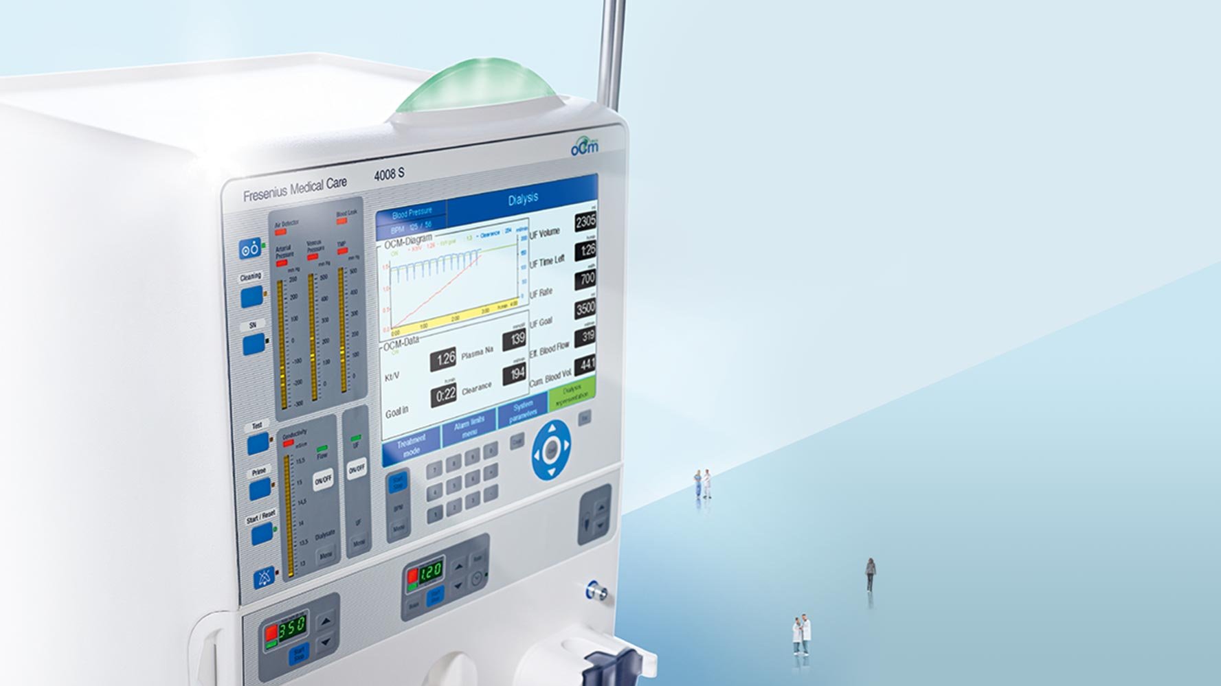
Практичный подход к качественному лечению
- Онлайн оценка эффективности и дозы диализа (ОСМ®)
- Ультрачистая диализная жидкость благодаря DIASAFE®plus
- Использование гигиенически чистого сухого бикарбоната в картриджах bibag®
- Адаптированный поток1 для оптимизации использования ресурсов
Основные характеристики
Настройки монитора артериального давления (BPM)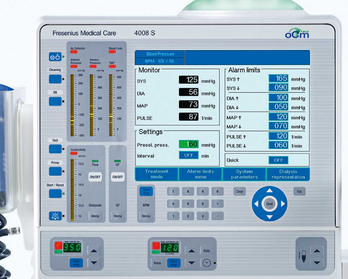
Обеспечение качества работы
Высокая оперативность
Процедура гемодиализа подразумевает большое количество необходимых ручных операций, связанных с управлением аппарата для гемодиализа и обеспечением непосредственно самой процедуры. Эргономичный дизайн и логичная структура меню управления в 4008S classix значительно облегчают процесс управления, а также быстрое и интуитивно понятное программирование параметров лечения. Важные параметры лечения представлены графически на TFT-LCD мониторе 10,4″, который отображает параметры в ходе процедуры лечения и обеспечивает быстрый доступ к истории лечения. Монитор артериального давления (BPM) полностью интегрирован, что в так же упрощает работу медицинского персонала. В сочетании с Системой управления данными терапии (TDMS) повседневная практика диализа может быть организована более эффективным и действенным образом, в полной мере используя сбор данных о каждой процедуре в режиме online и средства управления ходом процедуры.
Настройки для онлайн монитора клиренса (ОСМ®)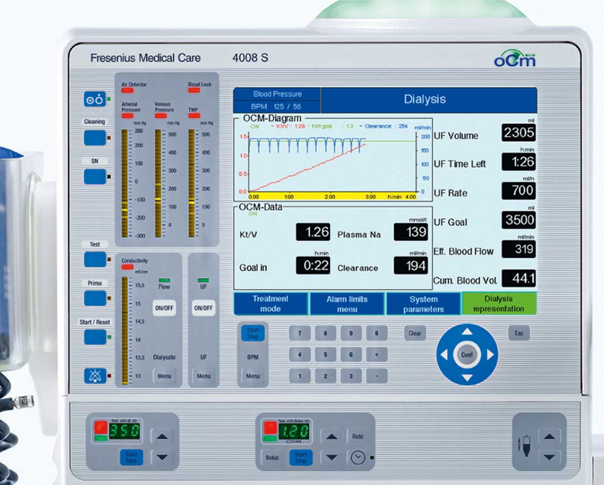
ОСМ® — онлайн монитор клиренса
Многочисленные исследования показали, что заболеваемость и смертность тесно коррелируют с обеспеченной дозой диализа. Онлайн монитор клиренса (ОСМ®) обеспечивает непрерывный контроль:
- Эффективности клиренса по мочевине in-vivo (K)
- Накопленной объём очищенной плазмы (Kt) или текущее значение выполненной дозы диализа (Kt/V)
- Концентрации натрия в плазме:
возможные отклонения от установленной цели терапии могут быть обнаружены оператором и исправлены непосредственно во время лечения * без дополнительных расходов на одноразовые материалы или дополнительных усилий.
Онлайн-монитор клиренса (ОСМ®) в комбинации с Монитором состава тела (ВСМ), измеряющим объем распределения мочевины V, обеспечивает точную оценку параметра Кт / V, согласующегося с традиционными методами, основанными на анализе проб крови.4
DIASAFE®plus — Фильтр диализной жидкости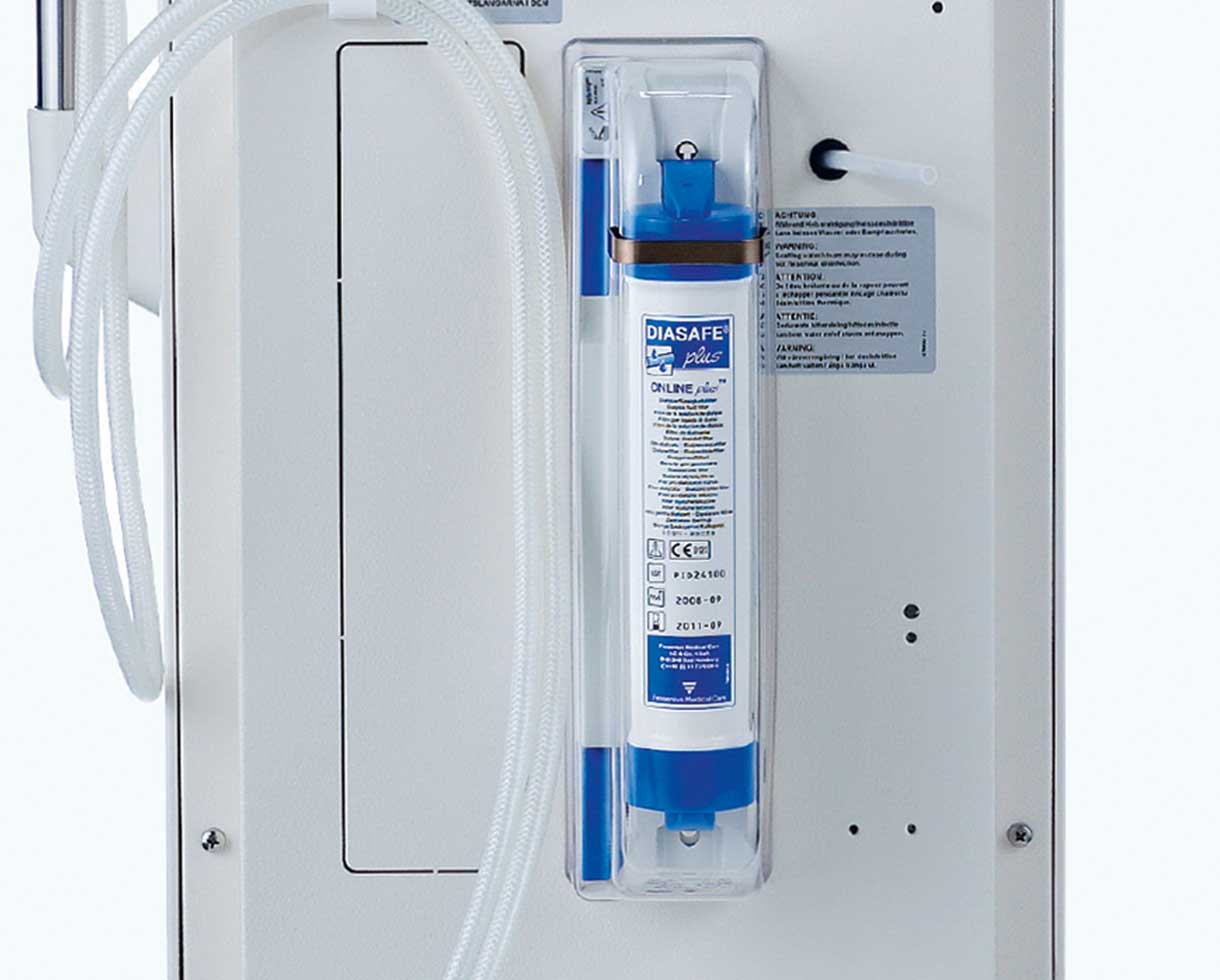
Обеспечение качества терапии
DIASAFE ® plus — Фильтр диализной жидкости
Качество и чистота диализной жидкости являются предметом серьезной озабоченности в современной заместительной почечной терапии, так как значительные объемы диализной жидкости вступают в контакт с кровью пациента во время каждой процедуры. Эндотоксины, присутствующие в диализной жидкости не отвечающей требованиям качества, могут вызвать нежелательные острые реакции и повлиять на долгосрочный результат пациентов на хроническом гемодиализе. Благодаря уникальным сорбционным свойствам мембраны волокон — Fresenius Polysulfone®, фильтр диализной жидкости DIASAFE® plus задерживать эндотоксины, что позволяет производить сверхчистую диализную жидкость. Кроме того, интеллектуальная концепция безопасности фильтра подразумевает:
- Функциональный контроль целостности фильтра
- Автоматический контроль срока службы фильтра
- Технологию асептического монтажа/демонтажа фильтра
Ультрачистая диализная жидкость признана неотъемлемой частью современного диализного оборудования. Естественно, что фильтр DIASAFE® plus является неотъемлемой частью базовой конфигурации всех современных диализных аппаратов Fresenius Medical Care.
bibag® — Сухой Бикарбонатный концентрат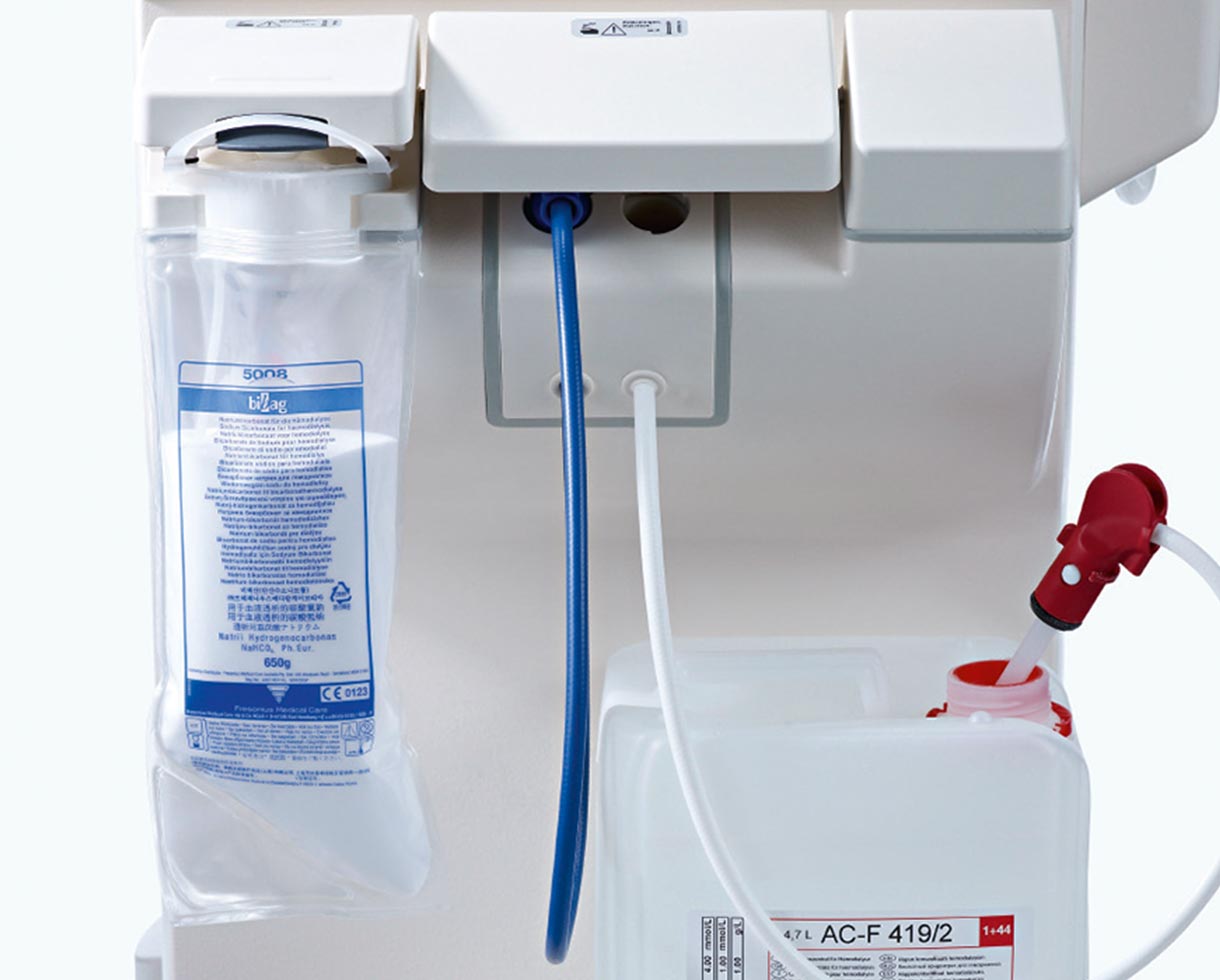
bibag® — Сухой Бикарбонатный концентрат
Чтобы избежать потенциального риска микробиологического загрязнения через жидкий бикарбонатный концентрат, бикарбонатный буфер всегда поставляется в виде сухого вещества. В дополнение к этому отличному гигиеническому стандарту, bibag® характеризуется:
- Простотой и эргономикой в использовании
- Сокращением требуемой площади для хранения
- Экологическими преимуществами за счет уменьшения объема отходов упаковки, уменьшения веса и объема при транспортировке
Основные особенности
Практичный подход к качественному лечению
Почти каждый второй пациент с тХПН умирает в результате сердечно-сосудистых заболеваний. Вот почему кардиопротективный гемодиализ является основным принципом Fresenius Medical Care как провайдера диализной помощи с более чем 100 летним опытом. Каждый наш шаг ориентирован на минимизацию сердечно-сосудистых рисков и продление жизни пациентов. 4008S classix продолжает историю успеха известной серии 4008, сочетая лучшее качество ГД лечения с надежностью и эксплуатационной эффективностью.
Аппарат для гемодиализа 4008S classix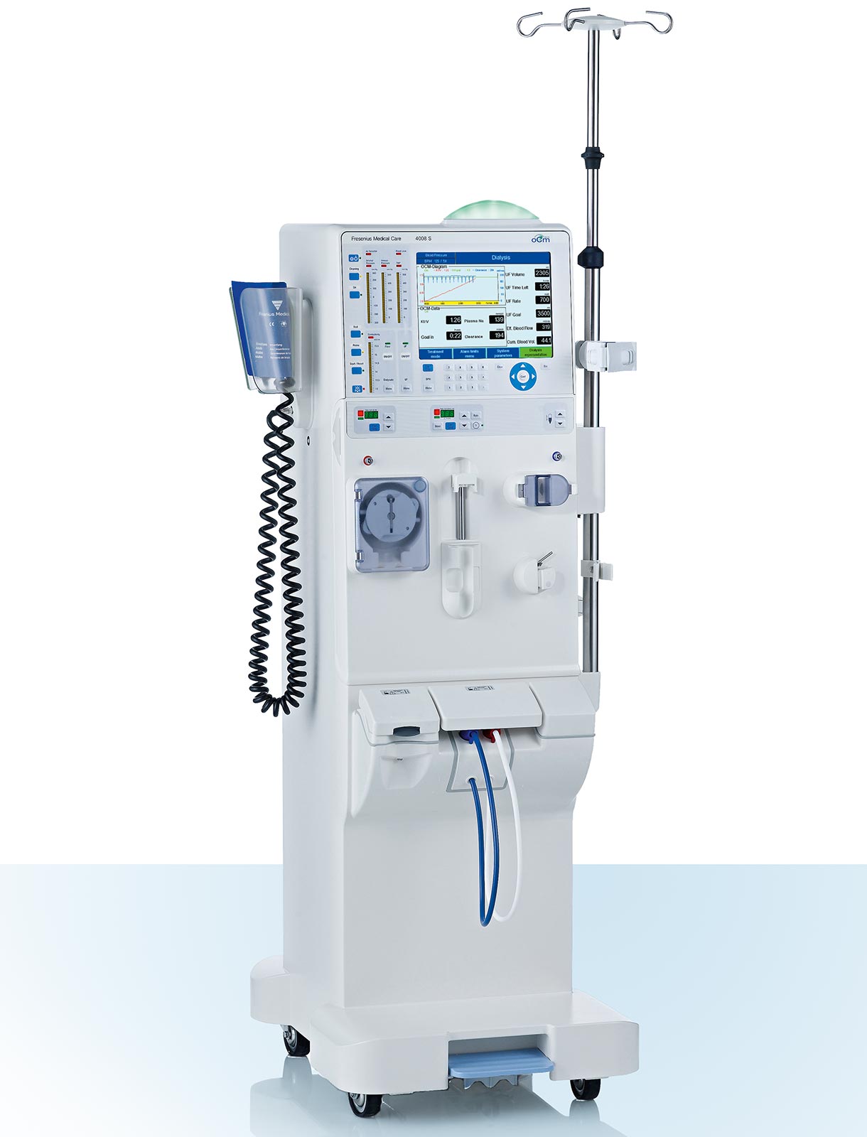
Доказанное качество
Последняя разработка в весьма успешной серии 4008
- Усовершенствованный контур диализной жидкости с высокоточной объемноконтролируемой ультрафильтрацией
- Надежная гидравлика
Передовое лечение
Высококачественный ГД для защиты Вашего пациента
- ОСМ® (Онлайн монитор клиренса)
- DIASAFE®plus (Фильтр для диализной жидкости)
- bibag® (Сухой бикарбонатный концентрат)
- Одноигольный режим или Одноигольный режим типа «клик-клак» (SN или SN Click-Clack)
Высокая оперативность
Экономически выгодное использование ресурсов
- Легкое, быстрое и интуитивно понятное управление
- TDMS (Система управления данными терапии)
- BPM (Монитор артериального давления)
- CDS (Централизованная система подачи концентрата)
- Адаптированный поток*
* Адаптированный поток доступен не во всех странах
Технические данные
Технические данные 4008S classix
| Общие данные | |
|---|---|
| Размеры 4008S Вес | 1370 x 500 x 650 мм (В x Д x Ш) (в том числе блокировка шунта и подставка) около 86 кг |
| Водоснабжение | |
| Давление воды на входе | 1,5 – 6,0 бар |
| Температура воды на входе | 5°C — 30°C; для «интегрированной горячей промывки» 85°C — 95°C |
| Максимальная высота слива | 1 м |
| Поставка концентрата | |
| Давление | 0 — 100 мбар; 1 м макс. высота всасывания |
| Центральное снабжение | 1 центральный концентрат кислоты (по желанию) 0 — 500 мбар |
| Данные электричества | |
| Мощность | 100 — 240 V AC, 50 — 60 Гц |
| Текущее потребление | Примерно 9 A (при 230 V) and 15 A (при 110 V) |
| Внешние соединения | Сетевой интерфейс для обмена данными с системой управления данными терапии (опционально); вход / выход для подключения внешнего вспомогательного оборудования; тревожный вход / выход (например, для вызова медсестры); диагностика компьютера домашнего диализа |
| Батарея | 18 V; 3 Ah (бесперебойная) |
Экстракорпоральный контур
| Экстракорпоральный контур | |
|---|---|
| Мониторинг артериального давления | |
| Диапазон дисплея | — 300 мм рт.ст. до + 280 мм рт.ст. |
| Точность | ±10 мм рт.ст. |
| Разрешение | 20 мм рт.ст. |
| Мониторинг венозного давления | |
| Диапазон дисплея | — 60 мм рт.ст. до + 520 мм рт.ст. |
| Точность | ±10 мм рт.ст. |
| Разрешение | 20 мм рт.ст. |
| Мониторинг трансмембранного давления | |
| Диапазон дисплея | — 60 мм рт.ст. до + 520 мм рт.ст. |
| Разрешение | 20 мм рт.ст. |
| Насос артериальной крови | |
| Диапазон скорости кровотока | 15 — 600 мл/мин |
| Точность | ± 10% |
| Разрешение | 5 мл/мин |
| Система одной иглы (опционально) | С 2-мя насосами крови, контроль внутреннего давления / давления с изменяемым объемом хода (макс. 50 мл/мин) |
| Детектор пузырьков воздуха | Ультразвуковое измерение передачи в системе переливания крови, дополнительный оптический мониторинг венозного зажима |
| Гепариновый насос | Диапазон доставки: от 0 до 10 мл/ч Функция болюса: макс. 5 мл на размер болюсного шприца: 20 мл |
Контур диализной жидкости
| Контур диализной жидкости | |
|---|---|
| Диапазон потока диализной жидкости | |
| Выбирается | 0 – 300 – 500 – 800 мл/мин |
| AdaptedFlow*(выбирается) | Поток диализата адаптирован к эффективному кровотоку |
| Температура диализной жидкости | |
| Выбирается | 35°C — 39°C |
| Проводимость диализной жидкости | |
| Диапазон | 12,8 – 15,7 мS/см (25°C) |
| Точность | ± 0,1 мS/см |
| Разрешение | 0,1 мS/см |
| Кислотный компонент диализной жидкости | |
| Соотношение смешивания | 1 + 27.6 (возможны другие) |
| Диапазон регулировки | — 8 to + 8 ммоль/л |
| Кислотный компонент диализной жидкости | |
| Соотношение смешивания по умолчанию | 1 + 27,6 (возможны другие) |
| Диапазон регулировки | — 8 до + 8 ммоль/л |
| OCM® | Онлайн клиренс мониторинг |
| Точность клиренса K | ± 6% |
| Сухой концентрат бикарбоната | bibag® |
| Система фильтров диализной жидкости | DIASAFE®plus |
| Точность балансировки | ± 0,1 % в зависимости от общего объема диализата |
| Проверка поддержания давления | Циклически |
| Ультрафильтрация | |
| Скорость УФ | 0 – 4 000 мл/ч (при шаге 1 мл/ч) |
| Точность объема насоса | ± 1% |
| Отображаемые параметры | цель УФ, время УФ, скорость УФ, объем УФ |
| Детектор утечки крови | |
| Чувствительность | ≤ 0,5 мл крови/мин (Hct = 25) при макс. потоке 800 мл/мин |
| BPM (Опционально) | |
| Диапазон экрана | Систола: 30 мм рт.ст.- 280 мм рт.ст. |
| Диастола: 10 мм рт.ст.- 240 мм рт.ст. | |
| MAP: 20 мм рт.ст.- 255 мм рт.ст. | |
| Пульс: 20 — 245 уд/мин | |
| Точность | ± 3 мм рт.ст. |
| Разрешение | 1 мм рт.ст. |
Программы дезинфекции и очистки **
| Программы дезинфекции и очистки** | |
|---|---|
| Промывание Температура/поток |
37 °C / 600 мл/мин |
| Горячая промывка (рециркуляция) Температура/поток |
84 °C / 450 мл/мин |
| Встроенная горячая промывка Температура/поток |
84°C / 450 мл/мин |
| Очистка Sporotal®100 (рециркуляция) Температура/поток |
37 °C / 600 мл/мин |
| Тепловая дезинфекция Диастерил®/Цитростерил® (рециркуляция) Температура/поток |
84° C / 450 мл/мин |
| Дезинфекция Пуристерил® 340/плюс (рециркуляция) Температура/поток |
37 °C / 600 мл/мин |
* Доступно не во всех странах.
** Различные комбинации программ на выбор. Технические изменения сохранены.
Узнать больше о продукции CorDiax

4008 E / 4008 B / 4008 H / 4008 S
Hemodialysis Machine
Technical Manual
Fresenius Medical Care
Important Information
Organization of the Technical Manual
Page identification
Page identification 1-3 is to be interpreted as: Chapter 1, page 3.
Editorial information
This Technical Manual has been updated to
4/09.03 = 4th edition, September 2003
In case of updates, the pages concerned will be replaced.
Refer to the table below to verify that the Technical Manual is up-to-date.
Modifications
Part number: 672 079 1
Page(s)
Current version
0-1
0-2 – 0-4
0-5 – 0-6
4/09.03
4/08.03
4/09.03
1-1 – 1-6
1-7
1-8 – 1-98
4/08.03
4/09.03
4/08.03
2-1 – 2-30
4/09.03
3-1 – 3-22
3-23
3-24 – 3-30
4/08.03
4/09.03
4/08.03
4-1 – 4-34
4/08.03
5-1 – 5-32
4/08.03
6-1 – 6-64
4/08.03
7-1 – 7-2
4/08.03
8-1 – 8-298
4/09.03
Manual changes will be released as new editions, supplement sheets or product
information. In general, this manual will be subject to modification.
Fresenius Medical Care 4008
4/08.03 (TM)
4/09.03
0-1
How to use the technical manual
Intended use
This Technical Manual is intended for service technicians. It can be used both for
first studies (to acquire a basic knowledge) and for reference purposes (for TSC,
maintenance and repair). The study of this manual, however, does not replace
the training courses offered by the manufacturer.
Requirements
Knowledge of the current Operating Instructions for the respective system.
Experience in mechanics, electrical and medical engineering.
Specifications
For the specifications of the respective system, refer to the current Operating
Instructions.
Circuit diagrams and
component layouts
The identification on the PCB permits the user/technician to verify if the circuit
diagram/component layout matches the PCB actually installed in the system.
Explanation of the Note and Caution symbols used
☞
Note
Informs the operator that in case of a failure to follow the steps as described, a
specific function will be executed incorrectly or will not be executed at all, or will
not produce the desired effect.
Caution
Advises the operator against certain procedures or actions that could cause
damage to the equipment or may have adverse effects on operators and
patients.
0-2
Fresenius Medical Care 4008 4/08.03 (TM)
Instructions to be Observed when Servicing the System
Authorized persons
Assembly, extensions, adjustments, modifications or repairs may only be carried
out by the manufacturer or persons authorized by him.
Test equipment
and accessories
The activities described in the Technical Manual require the availability of the
necessary technical test equipment and accessories.
Precautions
When working on the open system, the following precautions must be respected:
– Protect the components against ingress of fluids.
– Do not touch live parts (e. g. connectors of the power cord or heater).
ESD precautions
When repairing and when replacing spare parts, observe the applicable ESD
precautions (e.g. EN 100 015-1).
Fresenius Medical Care 4008
4/08.03 (TM)
0-3
Addresses
Please address any inquires to:
Manufacturer
Fresenius Medical Care AG
D-61346 Bad Homburg
Telefon: +49-6172-609-0
www.fmc-ag.com
Service Central Europe Fresenius Medical Care
Deutschland GmbH
Geschäftsbereich Zentraleuropa
Kundendienst / Service-Center
Steinmühlstraße 24b
D-61352 Bad Homburg
Telefon: +49-6172-609-7100
Fax: +49-6172-609-7102
E-mail: [email protected]
International Service
Fresenius Medical Care
Deutschland GmbH
Service Support International
Hafenstraße 9
D-97424 Schweinfurt
Telefon: +49-9721-678-333 (Hotline)
Fax: +49-9721-678-130
Local Service
0-4
Fresenius Medical Care 4008 4/08.03 (TM)
Table of contents
Section
Page
1
1.1
1.2
1.3
Description of machine functions and malfunctions ...............................................
Description of the T1 test ................................................................................................
Functional description of the modules ............................................................................
Functional description of the hydraulic unit .....................................................................
11-3
1-78
1-83
2
2.1
2-
2.3
Technical safety checks / Technical measurement checks / Maintenance ............
Technical safety checks and maintenance
for 4008 hemodialysis systems and options ...................................................................
Technical measurement checks and maintenance ki
for options of 4008 hemodialysis systems ......................................................................
TSC checklist ..................................................................................................................
3
3.1
3.2
3.3
3.4
Adjustment instructions ...............................................................................................
Overview of the DIP switches in the 4008 ......................................................................
Calibration mode .............................................................................................................
Hydraulics .......................................................................................................................
Air detector ......................................................................................................................
33-11
3-15
3-17
3-29
4
Calibration program ......................................................................................................
4-
5
5.1
5.2
5.3
5.4
5.5
5.6
5.7
5.8
5.9
5.10
5.11
5.12
Diagnostics program ....................................................................................................
General notes .................................................................................................................
Menu structure ................................................................................................................
Reading the analog inputs of CPU I ...............................................................................
Reading the analog inputs of CPU II ..............................................................................
Reading the digital inputs of CPU I .................................................................................
Reading the digital inputs of CPU II ................................................................................
Writing the analog outputs of CPU I ...............................................................................
Writing the analog outputs of CPU II ..............................................................................
Writing the digital outputs of CPU I .................................................................................
Writing the digital outputs of CPU II ................................................................................
Writing/Reading the digital outputs of CPU I ..................................................................
ONLINE plus™ module .....................................................................................................
55-3
5-5
5-7
5-9
5-10
5-15
5-19
5-20
5-21
5-27
5-30
5-31
6
6.1
6.2
6.3
6.4
Setup menu ...................................................................................................................
Übersicht Setup-Einstellungen .......................................................................................
Overview .........................................................................................................................
Main menu 4008 E/B Rev. 5.2 ........................................................................................
Main menu 4008 H/S Rev. 4.3 ........................................................................................
66-3
6-7
6-9
6-35
7
Miscellaneous ...............................................................................................................
7-
2.2
Fresenius Medical Care 4008
4/08.03 (TM)
4/09.03
2-3
2-23
2-29
0-5
Section
8
8.1
8.2
8.3
8.4
8.5
8.6
8.7
8.8
8.9
8.10
8.11
8.12
8.13
8.14
8.15
8.16
8.17
8.18
8.19
8.20
8.21
8.22
8.23
8.24
8.25
8.26
8.27
8.28
8.29
8.30
8.31
8.32
8.33
0-6
Page
Circuit diagrams and circuit descriptions ..................................................................
Block diagram 4008 ........................................................................................................
AC diagram 4008 E/H .....................................................................................................
AC diagram 4008 B/S .....................................................................................................
Block diagram of voltage supply .....................................................................................
Block diagram of Screen 4008 H/S .................................................................................
Connection layout diagram .............................................................................................
P.C.B. LP 450-2 Level detector control (LD) ..................................................................
P.C.B. LP 493 Blood leak detector .................................................................................
P.C.B. LP 624 Control board (BP) ..................................................................................
P.C.B. LP 630 Motherboard ............................................................................................
P.C.B. LP 631 CPU 1 ......................................................................................................
P.C.B. LP 632 CPU 2 ......................................................................................................
P.C.B. LP 633 Input board ..............................................................................................
P.C.B. LP 634 Output board ...........................................................................................
P.C.B. LP 635 Display board ..........................................................................................
P.C.B. LP 636 External connectors ................................................................................
P.C.B. LP 638 Power supply ..........................................................................................
P.C.B. LP 639 Power logic .............................................................................................
P.C.B. LP 950 Control board (HEP) ...............................................................................
P.C.B. LP 644-4 Display board (HEP) ............................................................................
P.C.B. LP 645 Position sensor membrane pump ..........................................................
P.C.B. LP 647 Power logic A (4008 B/S) ........................................................................
P.C.B. LP 649-2 Display board (4008 B/S) .....................................................................
P.C.B. LP 742 Interference filter .....................................................................................
P.C.B. LP 743 Power control 2 (4008 B/S) .....................................................................
P.C.B. LP 744 Power control 1 (4008 B/S) .....................................................................
P.C.B. LP 747 Distribution board ....................................................................................
P.C.B. LP 748 Display board (BP) ..................................................................................
P.C.B. LP 763 Multi interface board ...............................................................................
P.C.B. LP 922 Display board (4008 S) ...........................................................................
P.C.B. LP 923 Traffic light (4008 H/S) ............................................................................
P.C.B. LP 924 Display board (4008 H) ...........................................................................
P.C.B. LP 941 Hydraulics processor ..............................................................................
Fresenius Medical Care 4008 4/09.03
4/08.03 (TM)
88-5
8-7
8-9
8-11
8-13
8-15
8-19
8-31
8-35
8-45
8-53
8-65
8-85
8-105
8-129
8-147
8-151
8-159
8-171
8-179
8-183
8-187
8-195
8-213
8-217
8-223
8-227
8-233
8-237
8-245
8-261
8-265
8-281
Table of contents
1 Description of machine functions and malfunctions
Section
Page
1.1
1.1.1
1.1.2
1.1.3
1.1.4
1.1.5
1.1.6
Description of the T1 test .............................................................................................
T1 test flow diagram, serial program steps .....................................................................
T1 test flow diagram, parallel program steps ..................................................................
Description of the T1 test incl. error messages .............................................................
Description of machine errors during the cleaning programs ........................................
Error messages after turning power on ..........................................................................
Error messages during dialysis .......................................................................................
1-3
1-3
1-5
1-7
1-53
1-70
1-71
1.2
1.2.1
1.2.2
1.2.3
1.2.4
Functional description of the modules .......................................................................
Blood pump (arterial) ......................................................................................................
Blood pump (single needle), optional .............................................................................
Heparin pump .................................................................................................................
Air detector ......................................................................................................................
1-78
1-78
1-79
1-80
1-82
1.3
Functional description of the hydraulic unit .............................................................
Fig.: Flow diagram ..........................................................................................................
Description of the hydraulic unit ......................................................................................
Theory of operation of the balancing chamber ..............................................................
Central delivery system option ........................................................................................
Program runs during the cleaning programs ..................................................................
Fig.: Flow chart of cleaning programs – overview .........................................................
1-83
1-83
1-85
1-87
1-91
1-92
1-92
1.3.1
1.3.2
1.3.3
1.3.4
Fresenius Medical Care 4008
4/08.03 (TM)
1-1
1-2
Fresenius Medical Care 4008 4/08.03 (TM)
1.1
Description of the T1 test
1.1.1
T1 test flow diagram, serial program steps
MODULE
T1
TEST
ACCUMULATOR
START T1 TEST
TEST OK
?
no
STORAGE
ERROR NUMBER
no
STORAGE
ERROR NUMBER
no
STORAGE
ERROR NUMBER
no
STORAGE
ERROR NUMBER
no
STORAGE
ERROR NUMBER
no
STORAGE
ERROR NUMBER
no
STORAGE
ERROR NUMBER
no
STORAGE
ERROR NUMBER
yes
TEST
BYPASS
TEST OK
?
TEST
BLOOD LEAK DETECTOR
no
STORAGE
ERROR NUMBER
TEST OK
?
yes
yes
TEST
OPT. DETECTOR
TEST OK
?
TEST
TEMPERATURE
no
STORAGE
ERROR NUMBER
TEST OK
?
yes
yes
TEST
BLOOD SYSTEM
TEST OK
?
NEG. PRESSURE
HOLDING TEST
no
STORAGE
ERROR NUMBER
TEST OK
?
yes
yes
TEST
VENOUS PRESSURE
TEST OK
?
POS. PRESSURE
HOLDING TEST
no
STORAGE
ERROR NUMBER
TEST OK
?
yes
yes
TEST
AIR DETECTOR
TEST OK
?
TEST
UF-FUNCTION
no
STORAGE
ERROR NUMBER
TEST OK
?
yes
yes
TEST
DISPLAY
TEST OK
?
TEST
CONDUCTIVITY
no
STORAGE
ERROR NUMBER
TEST OK
?
yes
yes
TEST
ARTERIAL PRESSURE
TEST OK
?
TEST
DIASAFE/HDF FILTER
no
STORAGE
ERROR NUMBER
TEST OK
?
yes
yes
1
Fresenius Medical Care 4008
4/08.03 (TM)
1-3
1
T1 TEST
UNSUCCESSFUL
no
yes
DIALYSIS START KEY
INCORRECT
TEST STEP
RETURN
TEST OK
?
no
ERROR
DISPLAY
yes
FURTHER
INCORRECT
TEST STEPS
yes
NEXT INCORRECT
TEST STEP
no
RETURN
1-4
Fresenius Medical Care 4008 4/08.03 (TM)
1.1.2
T1 test flow diagram, parallel program steps
MODULE
T1
START T1 TEST
TEST
OPT. DETECTOR
TEST
BLOOD SYSTEM
yes
TEST OK
?
no
yes
TEST OK
?
TEST OK
?
no
1
STORAGE
ERROR NUMBER
TEST
BYPASS
STORAGE
ERROR NUMBER
TEST
VENOUS PRESSURE
TEST
TEMPERATURE
yes
TEST OK
?
TEST OK
?
no
STORAGE
ERROR NUMBER
TEST
AIR DETECTOR
NEG. PRESSURE
HOLDING TEST
yes
TEST OK
?
no
TEST OK
?
no
Conductivity?
yes
1
STORAGE
ERROR NUMBER
yes
TEST OK
?
no
1
STORAGE
ERROR NUMBER
yes
TEST
BLOOD LEAK DETECTOR
yes
yes
TEST OK
?
no
1
STORAGE
ERROR NUMBER
yes
TEST
CONDUCTIVITY
yes
no
STORAGE
ERROR NUMBER
TEST
CONDUCTIVITY
TEST
UF-FUNCTION
yes
no
TEST OK
?
no
STORAGE
ERROR NUMBER
STORAGE
ERROR NUMBER
TEST
DIASAFE/HDF FILTER
STORAGE
ERROR NUMBER
no
TEST OK
?
STORAGE
ERROR NUMBER
no
TEST
ARTERIAL PRESSURE
yes
TEST OK
?
1
STORAGE
ERROR NUMBER
STORAGE
ERROR NUMBER
no
TEST OK
?
yes
TEST OK
?
no
no
1
STORAGE
ERROR NUMBER
TEST OK
?
TEST
ACCUMULATOR
no
STORAGE
ERROR NUMBER
TEST OK
?
yes
no
STORAGE
ERROR NUMBER
POS. PRESSURE
HOLDING TEST
TEST
DISPLAY
POS. PRESSURE
HOLDING TEST
yes
TEST OK
?
yes
no
STORAGE
ERROR NUMBER
TEST
UF-FUNCTION
yes
1
TEST OK
?
no
STORAGE
ERROR NUMBER
Fresenius Medical Care 4008
TEST
DIASAFE/HDF FILTER
yes
1
TEST OK
?
no
yes
1
STORAGE
ERROR NUMBER
4/08.03 (TM)
1-5
1
T1 TEST
UNSUCCESSFUL
no
yes
DIALYSIS START KEY
INCORRECT
TEST STEP
RETURN
TEST OK
?
no
ERROR
DISPLAY
no
NEXT INCORRECT
TEST STEP
yes
FURTHER
INCORRECT
TEST STEPS
yes
RETURN
1-6
Fresenius Medical Care 4008 4/08.03 (TM)
1.1.3
Description of the T1 test incl. error messages
● Notes on the descriptions of errors
The values specified are internal mathematical values, which are used in the program.
Resolutions and tolerances are as follows:
1. Arterial pressure:
2. Venous pressure:
3. Dialysate pressure, coarse:
fine:
4. CD resolution:
5. Temperature:
3 mmHg/digit
3 mmHg/digit
6.0 mmHg/digit
0.5 mmHg/digit
0.06 mS/digit
0.05 °C/digit
and
and
and
and
and
and
± 1 digit of measured value.
± 1 digit of measured value.
± 1 digit of measured value.
± 1 digit of measured value.
± 1 digit of measured value.
± 1 digit of measured value.
● Prerequisites for starting and running the test
Error message
Description
Power failure
Power failure while the test is in progress
Dialines not conn
The dialysate lines are not in the interlock shunt.
Shunt Cover open
The interlock shunt is open.
Connect Conc.Line
Wrong conc. supply
The concentrate connector is in the rinse chamber, or concentrate is not connected at all. The error message depends on the
central delivery system preselected in the setup menu.
Blood Sensed by OD
The optical detector senses blood in the system.
Flow alarm
Line to or from the dialyzer kinked, malfunctions in the hydraulics.
Water alarm
Water supply interrupted.
● Overview of the individual test steps
Bypass test .....................................................................................................................
Optical detector test ........................................................................................................
Blood system test ............................................................................................................
Venous pressure system test .........................................................................................
Air detector test ...............................................................................................................
Display test .....................................................................................................................
Arterial pressure system test ..........................................................................................
Battery test ......................................................................................................................
Blood leak test ................................................................................................................
Temperature test .............................................................................................................
Negative pressure holding test .......................................................................................
Positive pressure holding test .........................................................................................
UF function test ...............................................................................................................
Conductivity test .............................................................................................................
Diasafe/HDF filter test .....................................................................................................
Fresenius Medical Care 4008
4/08.03 (TM)
4/09.03
1-8
1-10
1-12
1-16
1-18
1-22
1-24
1-26
1-28
1-30
1-32
1-34
1-39
1-42
1-44
1-7
● Bypass test
Test description:
Check of the following functions:
– Heater relay
– Bypass (electric)
– Check of the temperature range changeover
Illustration:
X632/A26
HOT_RINSE
LP 639
(4008E/H)
X639/
Power
Logic
A20
X632/A10
H_REL_W
X639/A12
X632/A9
EM_H_OFF
X639/A17
X632/C25
V24_EN
X632/C26
V24B_EN
X632/B22
CI
X632/A6
V26
X632/A6
V26
X632/A5
V24B
X634R/
X634R/
X632/A4
V24
A18
C22
LP 647
(4008S/B)
LP 632
CPU 2
X632/B28
LP 634
X634R/
Input
board
X631/A21
LP 631
LP 630
CPU 1
Output
board
X634L/A25
X631/A20
A23
X634L/C25
LP 633
X634L/C12
X632/B27
DATA BUS
(4008 B)
Display
board
LP 924
(4008 H)
LP 922
(4008 S)
Testgenerierung/Generation of Test
Rueckmeldung/Acknowledgement
1-8
Fresenius Medical Care 4008 4/08.03 (TM)
V24
V24B
V26
LP 649
(4008 E)
V24B
LP 635
V24
Mother
board
V26
X634R/
C24
Error description:
Error message
Description
F 01 Bypass
The heater relay is switched off.
– Acknowledgement (H_REL_W, X639/A12) → X632/A10, 0 V are
missing.
F 02 Bypass
The heater relay cannot be switched off by CPU2.
– Acknowledgement (H_REL_W, X639/Y12) → X632/A10, 12 V are
missing.
– Control line (EM_H_OFF, X632/A9) → X639/A17, 12 V are missing.
F 03 Bypass
The temperature measurement range is set to hot rinse.
– Control line (HOTRINSE, X634R/C24) → X639/A20, 0 V are missing.
– Acknowledgement (HOTRINSE, X634R/C24) → X632/A26, 0 V are
missing.
F 04 Bypass
The extended bypass cannot be correctly switched by CPU2 (V24 = off,
V26 = on, V24B = off).
– Acknowledgement (V24, X637/C1) → X632/A4, 24 V are missing.
– Acknowledgement (V26, X637/C2) → X632/A6, 0 V are missing.
– Acknowledgement (V24B, X637/C23) → X632/A5, 24 V are missing.
F 05 Bypass
The extended bypass cannot be correctly switched off by CPU2 (V24 =
on, V26 = off, V24B = on).
– Acknowledgement (V24, X637/C1) → X632/A4, 0 V are missing.
– Acknowledgement (V26, X637/C2) → X632/A6, 24 V are missing.
– Acknowledgement (V24B, X637/C23) → X632/A5, 0 V are missing.
F06 Bypass
CPU1 fails to set the temperature control to hot rinse.
– Control line (HOTRINSE, X634R/C24) → X639/A20, 12 V are missing.
– Acknowledgement (HOTRINSE, X634R/C24) → X632/A26, 12 V
are missing.
F 07 Bypass
The extended bypass cannot be correctly switched by CPU1 (V24 = off,
V26 = on, V24B = off).
– Acknowledgement (V24, X637/C1) → X632/A4, 24 V are missing.
– Acknowledgement (V26, X637/C2) → X632/A6, 0 V are missing.
– Acknowledgement (V24B, X637/C23) → X632/A5, 24 V are missing.
F08 Bypass
CPU1 fails to reset the temperature control to dialysis.
– Control line (HOTRINSE, X634R/C24) → X639/A20, 0 V are missing.
– Acknowledgement (HOTRINSE, X634R/C24) → X632/A26, 0 V are
missing.
F09 Bypass
The extended bypass cannot be correctly switched off by CPU1 (V24 =
on, V26 = off, V24B = on).
– Acknowledgement (V24, X637/C1) → X632/A4, 0 V are missing.
– Acknowledgement (V26, X637/C2) → X632/A6, 24 V are missing.
– Acknowledgement (V24B, X637/C23) → X632/A5, 0 V are missing.
F95 Bypass
System error
Fresenius Medical Care 4008
4/08.03 (TM)
1-9
● Optical detector test
Test description:
Attenuation of the optical detector.
Check of the acknowledgement of the optical detector.
Illustration:
LP 632
CPU 2
X632/C16
LDSA
X632/C15
ODSA
X632/A30
OD_OUT
X633L/C7
32/B27
LP 633
X632/B28
LP 634
Input
board
Output
board
31/A20
OD_IN
X633L/C8
X631/A21
LP 631
LP 630
CPU 1
DATA BUS
Mother
board
X351/5
LP 635
LP 649
(4008 E)
(4008 B)
X351/10
Display
board
LP 924
LP 922
(4008 H)
(4008 S)
Testgenerierung/Generation of Test
Rueckmeldung/Acknowledgement
1-10
Fresenius Medical Care 4008
X351/7
Pven
4/08.03 (TM)
Error description:
Error message
Description
F01 opt. Detector
CPU1 interprets the optical detector in a different way than does CPU2.
– Acknowledgement (OD_OUT, X633L/C7) → X632/A30 and the
digital input of P.C.B. LP 633 measure different levels.
F02 opt. Detector
CPU2 fails to recognize blood in the system.
– Acknowledgement (OD_OUT, X633L/C7) → X632/A30, 0 V are
missing.
– Detuning (ODSA, X632/C15) → X351/7 not 12V.
F03 opt. Detector
CPU1 fails to recognize blood in the system.
– Acknowledgement (OD_OUT, X633L/C7) → digital input on P.C.B.
LP 633.
– Detuning (ODSA, X632/C15) → X351/7 not 12V.
F04 opt. Detector
CPU2 recognizes that the optical detector senses opaque fluid (required because of the test in the cleaning program).
– Acknowledgement X632/A30 not 12V.
– AD28 defective.
F96 opt. Detector
System error.
Fresenius Medical Care 4008
4/08.03 (TM)
1-11
● Blood system test
Test description:
Check of the following functions:
– Blood alarm acknowledgement
– Blood pump switch-off
Illustration:
LP 632
X632/C10
CLP_CTL
X632/C14
LDA2
X632/C21
BL_AL
X632/B11
BPSB_VEN
X632/A11
BPSB_ART
X632/A15
SN_ART
CPU 2
X632/B28
X632/B27
X634L/
C15
Input
board
Output
board
A13 X633L/
LP 647
(4008S/B)
X634L/ B15
B14
LP 631
C14
BPSST_A
DATA BUS
LP 635
LP 649
(4008 E)
(4008 B)
LP 922
(4008 H)
(4008 S)
Testgenerierung/Generation of Test
Rückmeldung/Acknowledgement
Fresenius Medical Care 4008
4/08.03 (TM)
X351/6
X348/V3
X348/V6
X348a/1
X348a/3
Pven
Display
board
LP 924
X348a/6
X348a/2
BPSST_V
Mother
board
X351/8
LP 630
CPU 1
1-12
X634L/
X631/A21
X348/V1
X631/A20
(4008E/H)
A15
BPST_ART
X633L/
C13
LP 634
X634L/
A14
LP 633
Error description:
Error message
Description
F09 Bloodsystem
Acknowledgement that CPU2 recognizes that the arterial blood pump
is inactive (BP not running).
– Acknowledgement (BPSB_ART, X348a/6) → X632/A11, 12 V missing.
– Control line (BPSST_ART, X634L/B14) → X348a/1, 12 V missing or
(BPST_ART, X634L/A14) → X348a/3, 12 V are missing.
F10 Bloodsystem
Acknowledgement that CPU1 recognizes that the arterial blood pump
is inactive (BP not running).
– Acknowledgement (BPSB_ART, X348a/6) → X633L/A11, 12 V are
missing.
– Control line (BPSTT_ART, X634L/B14) → X348a/1, 12 V missing or
(BPST_ART, X634L/A14) → X348a/3, 12 V missing.
– Level is raised during the T1 test.
F11 Bloodsystem
The arterial blood pump cannot be stopped by CPU1.
CPU2 recognizes that the arterial blood pump remains active.
– Control line (BPSST_ART, X634L/B14) → X348a/1, 0 V missing,
as well as (BPST_ART, X634L/A14) → X348a/3, 0 V missing.
– Acknowledgement (BPSB_ART, X348a/6) → X632/A11, 0 V are
missing.
– The level is raised during the T1 test, or the up/down key on the air
detector is blocked and the level is constantly raised.
F12 Bloodsystem
The arterial blood pump cannot be stopped by CPU1.
CPU1 recognizes that the arterial blood pump remains active.
– Control line (BPSST_A, X634L/B14) → X348a/1, 0 V missing,
as well as (BPST_ART, X634L/A14) → X348a/3, 0 V missing.
– Acknowledgement (BPSB_ART, X348a/6) → X633L/A11, 0 V are
missing.
F13 Bloodsystem
Applicable for SW 4.91/2.91 and higher if SN, ONLINE-HDF or
4008 HDF pump is connected (= ADKS active)
Acknowledgement that CPU2 detects that the pump is inactive (pump
is not running).
– Acknowledgement (BPSB_VEN, X348V/6) → X632/ B11, 12V
missing
– Control line (BPSST_VEN, X634L/B15) → X348V/1, 12V missing or
(BPST_VEN, X634L/A15) → X348V/3, 12V missing
– Transistor T9 on P.C.B. LP754 defective
– IC5 on P.C.B. LP632 defective
– In 4008 HDF an HDF treatment was performed, followed by a
cleaning program with the substituate pump running, then the T1
test has been re-started.
The substituate pump must be switched off because otherwise the
test step will fail to be passed (problem was corrected with SW 3.20
in 4008 H/S systems: the substituate pump will be switched off
automatically on starting a cleaning program).
Fresenius Medical Care 4008
4/08.03 (TM)
1-13
1-14
F14 Bloodsystem
Applicable for SW 4.91/2.91 and higher if SN, ONLINE-HDF or
4008 HDF pump is connected (= ADKS active)
Acknowledgement that CPU1 detects that the pump is inactive (pump
is not running).
– Acknowledgement (BPSB_VEN,X348V/6) → X633L/A13, 12V
missing
– Control line (BPSST_VEN, X634L/B15) → X348V/1 not 12V or
(BPST_VEN, X634L/A15) → X348V/3 not 12V
– IC16 on P.C.B. LP633 defective
– P.C.B. LP633 recognizes Single-Needle pump although it is not
connected.
F15 Bloodsystem
Applicable for SW 4.91/2.91 and higher if SN, ONLINE-HDF or
4008 HDF pump is connected (= ADKS active)
CPU1 fails to stop the corresponding blood pump.
CPU2 detects that the pump remains active.
– Control line (BPSST_VEN, X634L/B15) → X348V/1, 0V missing as
well as (BPST_VEN, X634L/A15) → X348V/3 not 0V
– Acknowledgement (BPSB_VEN, X348V/6) → X632/B11, 0V missing
– Transistor T9 on P.C.B. LP754 defective
– IC5 on P.C.B. LP632 defective
– During the test the lines are inserted on the corresponding pump
using the Start/Stop key.
– P.C.B. LP633 recognizes Single-Needle pump although it is not
connected.
F16 Bloodsystem
Applicable for SW 4.91/2.91 and higher if SN, ONLINE-HDF or
4008 HDF pump is connected (= ADKS active)
CPU1 fails to stop the corresponding blood pump.
CPU1 detects that the pump remains active.
– Control line (BPSST_VEN, X634L/B15) → X348V/1 not 0V as well
as (BPST_VEN, X634L/A15) → X348V/3 not 0V
– Acknowledgement (BPSB_VEN, X348V/6) → X633L/A13 not 0V
– IC16 on P.C.B. LP633 defective
– P.C.B. LP633 recognizes Single-Needle pump although it is not
connected.
F17 Bloodsystem
Applicable for SW 4.91/2.91 and higher if SN, ONLINE-HDF or
4008 HDF pump is connected (= ADKS active)
Although the recognition of the venous blood pump (ADKS) is not
acknowledged, the 24-V supply voltage of the pump can be switched
off.
– Acknowledgement line (ADKS, X348V/7) → X633L/A10 not 12V
– Acknowledgement (BPSB_VEN, X348V/6) → X633L/A13 not 12V
– Acknowledgement (BPSB_VEN, X348V/6) → X632/B11 not 12V
– Online-HDF has already been switched on during the T1 test.
– IC16 on P.C.B. LP633 defective.
Fresenius Medical Care 4008
4/08.03 (TM)
F18 Bloodsystem
Applicable for SW 5.00/4.10 and higher, check of the BPUS signal
(CPU, P.C.B. LP 632)
At the beginning of the test step a maximum of 40s may pass until
rotation has stopped.If the blood pump is being activated, the rotation
stop alarm must have been cleared.
– Acknowledgement line (BPUS, X348A/8) → X632/A13 not 0V
– Acknowledgement line (BPUS, X348A/8) → X632/A13 not 12V
– Blood pump speed is set to “0”: preset speed during the T1 test.
F19 Bloodsystem
Applicable for SW 5.00/4.10 and higher, check of the BPUS signal
(CPU, P.C.B. LP 631 via LP 633)
At the beginning of the test step a maximum of 40s may pass until
rotation has stopped. If the blood pump is being activated, the rotation
stop alarm must have been cleared.
1. Acknowledgement line (BPUS, X348A/8) → X633L/A12 not 0V
2. Acknowledgement line (BPUS, X348A/8) → X633L/A12 not 12V
F95 Bloodsystem
System error.
Fresenius Medical Care 4008
4/08.03 (TM)
1-15
● Venous pressure system test
Test description:
Verification of the lower limit by checking the venous zero point.
The upper limit is tested by detuning the venous pressure unit in positive direction.
(The venous line clamp is closed during the test.)
Illustration:
LP 632
X632/C16
LDSA
X632/C18
PV_DET
X632/C17
P_VEN
CPU 2
X632/B27
X632/B28
LP 633
Input
board
X631/A20
Output
board
X634R/C18
VENT_V
X633L/B5
LP 634
X631/A21
LP 631
LP 630
CPU 1
DATA BUS
Mother
board
X351/1
LP 635
LP 649
(4008 E)
(4008 B)
Display
board
LP 924
LP 922
(4008 H)
(4008 S)
X351/4
Testgenerierung/Generation of Test
Rueckmeldung/Acknowledgement
1-16
Fresenius Medical Care 4008
X351/2
P VEN
4/08.03 (TM)
X351/10
Error description
Error message
Description
F01 Venous
CPU1 (input board) shows a venous zero point deviation of more than
±12 mmHg (60 s).
– Control (VENT_VALVE, X634R/C18) → X351/1 of the vent valve in
the LD is defective.
– Acknowledgement (P_VEN, X351/4) → X633L/B5 that the voltage
value is outside the zero point tolerance.
– P-venous has not been calibrated.
F02 Venous
CPU2 shows a venous zero point deviation of more than ±12 mmHg
(60 s).
– Control (VENT_VALVE, X634R/C18) → X351/1 of the vent valve in
the LD is defective.
– Acknowledgement (P_VEN, X351/4) → X632/C17, the voltage
value is outside the zero point tolerance.
– P-venous has not been calibrated.
F03 Venous
With detuning in positive direction, the achieved change in the venous
display is less than 100 mmHg (7 s).
– The test detuning is defective (PV_DET, X632/C18) → X351/2.
– Acknowledgement (P_VEN, X351/4) → X633L/B5, the change in
voltage is too low.
– P-venous has not been calibrated.
F04 Venous
The deviation in the measured value between CPU1 and CPU2 is
higher than ±12 mmHg (if Pven > 100 mmHg).
– Acknowledgement (P_VEN, X351/4) → X633L/B5 and X632/C17
measure different voltage values.
– P-venous has not been calibrated.
F95 Venous
System error.
Fresenius Medical Care 4008
4/08.03 (TM)
1-17
● Air detector test
Test description:
– Test of the air detector by checking the alarm state.
– Switch-off of the venous line clamp in the air detector module.
Illustration:
1-18
Fresenius Medical Care 4008
4/08.03 (TM)
Error description:
Error message
Description
F01 Airdetector
CPU1 interprets the air detector signal in a different way than does
CPU2.
– Acknowledgements (LDA1, X351/14) → X632/C13 and X633L/C10
recognize different signal levels.
F02 Airdetector
The air detector alarm is not recognized by CPU2.
– Acknowledgement (LDA1, X351/14) → X632/C13, 0 V are missing.
– Transmission weakening (LDSA, X632/C16) → X351/10, 12 V are
missing.
F03 Airdetector
Air detector clamps acknowledgement (CPU2) activated (clamp
closed).
– Acknowledgement (LDA2, X351/6) → X632/C14, 24 V are missing.
– Clamp control (CLP_CTL, X634L/C14) → X351/8, 12 V are missing.
– Clamp control (CLP_CTL, X632/C10) → X351/8, 12 V are missing.
F04 Airdetector
Air detector clamps acknowledgement (CPU1) activated (clamp
closed).
– Acknowledgement (LDA2, X351/6) → X633L/C13, 24 V are missing.
– Clamp control (CLP_CTL, X634L/C14) → X351/8, 12 V are missing.
– Clamp control (CLP_CTL, X632/C10) → X351/8, 12 V are missing.
F05 Airdetector
The blood alarm signal has not been cleared (indicates an alarm).
– Acknowledgement (BL_AL, X634L/C15) → X632/C21, 12 V are
missing.
If the HDF option is used, this signal is not tested (special function).
F06 Airdetector
Closing of the air detector clamp via the CPU2 control line was not
possible.
– Clamp control (CLP_CTL, X632/C10) → X351/8, 0 V are missing.
– Acknowledgement (LDA2, X351/6) → X632/C14, 0 V are missing.
F07 Airdetector
Opening of the air detector clamp via the CPU2 control line was not
possible.
– Clamp control (CLP_CTL, X632/C10) → X351/8, 12 V are missing.
– Acknowledgement (LDA2, X351/6) → X632/C14, 24 V are missing.
F08 Airdetector
Closing of the air detector clamp via the CPU1 control line was not
possible, or CPU2 acknowledgement is incorrect.
– Clamp control (CLP_CTL, X634L/C14) → X351/8, 0 V are missing.
– Acknowledgement (LDA2, X351/6) → X632/C14, 0 V are missing.
Fresenius Medical Care 4008
4/08.03 (TM)
1-19
F09 Airdetector
Closing of the air detector clamp via the CPU1 control line was not
possible, or CPU1 acknowledgement is incorrect.
– Clamp control (CLP_CTL, X634L/C14) → X351/8, 0 V are missing.
– Acknowledgement (LDA2, X351/6) → X633L/C13, 0 V are missing.
F10 Airdetector
The blood alarm message is missing.
– Acknowledgement (BL_AL, X634R/C15) → X632/C21, 0 V are
missing.
If the HDF option is used, this signal is not tested (special function).
F11 Airdetector
Air detector clamps acknowledgement (CPU2) activated (clamp
closed).
– Acknowledgement (LDA2, X351/6) → X632/C14, 24 V are missing.
– Clamp control (CLP_CTL, X634L/C14) → X351/8, 12 V are missing.
– Clamp control (CLP_CTL, X632/C10) → X351/8, 12 V are missing.
F12 Airdetector
Air detector clamps acknowledgement (CPU1) activated (clamp
closed).
– Acknowledgement (LDA2, X351/6) → X633L/C13, 24 V are missing.
– Clamp control (CLP_CTL, X634L/C14) → X351/8, 12 V are missing.
– Clamp control (CLP_CTL, X632/C10) → X351/8, 12 V are missing.
F13 Airdetector
The blood alarm signal has not been cleared (indicates alarm).
– Acknowledgement (BL_AL, X634L/C15) → X632/C21, 12 V are
missing.
If the HDF option is used, this signal is not tested (special function).
1-20
F14 Airdetector
Raise level key on the air detector is constantly active.
– Acknowledgement (LEVEL_UP, X351/3) → X632/C11 not 0V.
F15 Airdetector
Acknowledgement of the supply voltage for the ultrasonic output stage
not between 6.5 and 13.5 V after 3 seconds.
– Adapter board AD28 not connected
– Acknowledgement (X351/11 → X633L/25A jumper to X633L/B7)
not 12V.
– Relay on AD28 failed to drop.
F16 Airdetector
Acknowledgement of the supply voltage for the ultrasound output stage
not >14.5V after 3 seconds.
– Adapter board AD28 not connected.
– Acknowledgement (X351/11 → X633L/25A jumper to X633L/B7)
not 16V/24V.
– Relay on AD28 is not controlled.
– No 10-Hz signal at ALARM_REST (X351/12)
Fresenius Medical Care 4008
4/08.03 (TM)
F17 Airdetector
Acknowledgement of the supply voltage for the ultrasound output stage
not between 6.5 and 13.5 V after 3 seconds.
– Adapter board AD28 not connected
– Acknowledgement (X351/11 → X633L/25A jumper to X633L/B7)
not 12V
– Relay on AD28 failed to drop
F95 Airdetector
System error.
Fresenius Medical Care 4008
4/08.03 (TM)
1-21
● Display test
Test description:
Check of all displays and indicators on the monitor front
– Display test
– Status LED
– Alarm LED
– Seven-segment display, all dark
– Seven-segment display, all 8888
– Bar graph
– CPU1/CPU2 alarm tone
This display test must be monitored by the user!
Illustration:
LP 632
CPU2_AL
X632/C29
CPU 2
X634R/A16
LP 633
Input
board
X632/ B28
X632/ B27
LP 634
Output
board
+LS X634L/A13
-LS X634L/B13
X631/ A21
X631/ A20
LP 631
LP 630
CPU 1
DATA BUS
Mother
board
LP 635
LP 649
(4008 E)
(4008 B)
Test Display
Display
board
LP 924
LP 922
(4008 H)
(4008 S)
8888
8888
8888
8888
Testgenerierung/Generation of Test
Rueckmeldung/Acknowledgement
1-22
Fresenius Medical Care 4008
4/08.03 (TM)
Error description:
Error message
Description
F01 Display
CPU1 failed to start the display test within 5 sec.
– The “test started” information transmitted via the serial interface is
missing.
F02 Display
CPU1 failed to complete the display test within 120 sec.
– The “test completed” information transmitted via the serial interface
is missing.
F95 Display
System error.
Fresenius Medical Care 4008
4/08.03 (TM)
1-23
● Arterial pressure system test
Test description:
Test of the arterial pressure unit by electronic detuning in positive or negative direction.
Illustration:
1-24
Fresenius Medical Care 4008
4/08.03 (TM)
Error description:
Error message
Description
F01 Arterial
With detuning in negative direction, the change achieved on the arterial
display is less than 100 mmHg (2 sec).
– Acknowledgement (P_ART, X348A/7) → X633L/B12, insufficient
voltage change.
– Test detuning defective (PA_DET, X632/A17) → X348A/9.
F02 Arterial
With detuning in positive direction, the change achieved on the arterial
display is less than 100 mmHg (2 sec).
– Acknowledgement (P_ART, X348A/7) → X633L/B12, insufficient
voltage change.
– Test detuning defective (PA_DET, X632/A17) → X348A/9.
F95 Arterial
System error.
Fresenius Medical Care 4008
4/08.03 (TM)
1-25
● Battery test
Test description:
Check of the battery voltage under load.
Illustration:
TESTBATT
LP 632
CPU 2
X634R/C23
LP 633
X632/B27
Input
board
X632/B28
X639/A10
LP 634
LP 639
(4008E/H)
Output
board
Power
Logic
LP 647
(4008S/B)
X633L/B21
X639/A2
X639/A3
X639/A4
X631/A21
X631/A20
LP 631
LP 630
CPU 1
DATA BUS
Mother
board
U_ACCU
Akku (16 - 22V)
LP 635
LP 649
(4008 E)
(4008 B)
Display
board
LP 924
LP 922
(4008 H)
(4008 S)
Testgenerierung/Generation of Test
Rueckmeldung/Acknowledgement
1-26
Fresenius Medical Care 4008
4/08.03 (TM)
Error description:
Error message
Description
F01 Accumulator
CPU1 failed to complete the battery test within 5 sec.
– The “test completed” information transmitted via the serial interface
is missing.
F02 Accumulator
The battery charge is insufficient for 15 min emergency operation
(maybe no battery connected).
– The battery voltage (U_ACCU, ...) → X633L/B21 dropped below
17.6 V.
– Acknowledgement (U_ACCU, ...) → X633L/B21 of the battery voltage defective.
F03 Accumulator
The test circuit on P.C.B. LP 639 defective.
– The test level is incorrect (TESTBATT, X634R/C23) → X639/A10,
the 12-V pulse is missing (100 ms).
– Power supply unit LP639 SI5 or in 4008B/S systems fuse in the
base defective.
– R39 on P.C.B. LP639 (4008E/H) or P.C.B. LP647 (4008B/S) defective, possibly caused by flickering power supply unit.
F95 Accumulator
System error.
Fresenius Medical Care 4008
4/08.03 (TM)
1-27
● Blood leak test
Test description:
Test of the blood leak detector by lowering the capacity of the transmitting diode.
Illustration:
1-28
Fresenius Medical Care 4008
4/08.03 (TM)
Error description:
Error message
Description
F01 Bloodleak
Blood leak channel and dimness not in alarm-free condition during the
T1 test.
– Dimness channel contaminated (calcium precipitate, etc.)
– Acknowledgement (BLL, X637A/18) → X633L/B10 voltage value
within the alarm tolerances (< 3V).
– Acknowledgement (BLL_DIM, X637A/21) → X633L/B11 voltage
value within the alarm tolerances (<1.5V/ >8V).
– DAC_BLL or DAC_DIM not within the tolerances (check calibration)
F02 Bloodleak
The blood leak alarm/dimness alarm is not recognized during test
detuning.
– Acknowledgement (BLL, X637A/18) → X633L/B10 voltage value
not within the alarm tolerances.
– Acknowledgement (BLL_DIM, X637A/21 → X633L/B11 voltage value not within the alarm tolerances (<1.5V)
– Test detuning (BLL_DET, X632/A25) → X633L/B27 not 5V
– Calibration of DAC_BLL or DAC_DIM is too high
– Detuning (DAC_DIM, X634R/A11) → X633L/C3 impossible
– Dimness calibration is set to potentiometer calibration (BR6 from
pos. 1/2 to 2/3).
F03 Bloodleak
After test detuning, the blood leak channel and dimness fail to enter the
alarm-free state.
– Dimness channel contaminated (calcium precipitate, etc.)
– Acknowledgement (BLL, X637A/18) → X633L/B10 voltage value
within the alarm tolerances
– Test detuning (BLL_DET, X632/A25) → X633L/B27 not 0V.
– Acknowledgement (BLL_DIM, X637A/21) → X633L/B11 voltage
value within the alarm tolerances (<1.5V / >8V).
– DAC_BLL or DAC_DIM not within the tolerances (check calibration)
F95 Bloodleak
System error.
Fresenius Medical Care 4008
4/08.03 (TM)
1-29
● Temperature test
Test description:
Test of the upper alarm limit by electronically detuning the temperature display in positive
direction.
Illustration:
LP 639
(4008E/H)
LP 632
CPU 2
X632/A26
HOTRINSE
X632/A24
T_DIAL1
Logic
LP 647
X632/A23
(4008S/B)
T_DETADJ
X633R/C21
LP 633
X632/B28
X632/B27
X633L/B16
X631/A21
LP 631
LP 630
CPU 1
X633R/C15
X631/A20
X633R/C25
Input
board
X633R/
A20
X634R/
A13
BIBAG_TE
LP 634
Output
board
X634R/C24
DATA BUS
LP 635
LP 649
(4008 E)
(4008 B)
NTC_BIB
MON_NTC
Mother
board
LP 922
(4008 H)
(4008 S)
(4008S/B)
Rueckmeldung/Acknowledgement
Fresenius Medical Care 4008
(4008E/H)
LP 647
Testgenerierung/Generation of Test
1-30
LP 639
Power
Logic
Display
board
LP 924
X639/A20
4/08.03 (TM)
Error description:
Error message
Description
F01 Temperature
The temperature measuring range is not set to hemodialysis.
– Control line (HOTRINSE, X634R/C24) → X639/A20, 0 V are missing.
– Acknowledgement (HOTRINSE, X634R/C24) → X632/A26, 0 V are
missing.
F02 Temperature
The actual temperature is less than 35.0 °C (test running time > 15
minutes).
– Calibrate the temperature.
– The heater rod failed.
– Acknowledgement (T_DIAL1, X633L/B16) → X632/A24, voltage got
stuck.
F03 Temperature
The actual temperature is higher than 39.0 °C (test running time > 15
minutes).
– Calibrate the temperature.
– The regulating sensor (NTC-2) is defective.
– Acknowledgement (T_DIAL1, X633L/B16) → X632/A24, voltage got
stuck.
F04 Temperature
The temperature failed to stabilize within 15 minutes.
– Acknowledgement (T_DIAL1, X633L/B16) → X632/A24 is steadily
changing (change > 0.3 °C/15 sec).
F05 Temperature
Detuning in positive direction not higher than 3 °C (10 sec).
– Acknowledgement (T_DIAL1, X633L/B16) → X632/A24, change in
voltage insufficient.
– Detuning (T_DETADJ, X632/A23) → X633R/C21 insufficient.
F06 Temperature
The monitor sensor indicates a constant value.
– NTC-3 defective.
F07 Temperature
The test release is missing (max. test running time is 10 minutes).
– Run-time problem (software).
F08 Temperature
CPU1 failed to transmit a Bibag status message within 3 sec.
– Run-time problem (software).
F09 Temperature
Bibag NTC_BIB detuning not higher than 1 °C.
– Acknowledgement (NTC_BIB, X633R/C15) → ADW on P.C.B.
LP 633, change in voltage insufficient.
– Detuning (BIBAG_TE, X634R/A13) → X633R/A20 insufficient.
F10 Temperature
Bibag temperature display outside of measuring range (15 to 45 °C).
– Acknowledgement (NTC_BIB, X633R/C15) → ADW on P.C.B.
LP 633.
F95 Temperature
System error.
Fresenius Medical Care 4008
4/08.03 (TM)
1-31
● Negative pressure holding test
Test description:
Within a specific time period, the actual value of the dialysate pressure transducer should change
within certain limits only.
Illustration:
LP 632
CPU 2
X632/B27
X632/A19
ACKN_ASP
X632/B22
CI
X632/C27
UF_P_CTL
X632/A29
P_DIAL
X632/B28
X633L/B6
LP 633
Input
board
LP 634
Output
board
X633R/C28
X631/A20
X634R/A24
X631/A21
LP 631
LP 630
CPU 1
DATA BUS
LP 649
(4008 E)
(4008 B)
Display
board
LP 924
LP 922
(4008 H)
(4008 S)
Testgenerierung/Generation of Test
Rueckmeldung/Acknowledgement
1-32
Fresenius Medical Care 4008
4/08.03 (TM)
UF_P_CTL
+P_DIAL
Mother
board
LP 635
X634R/A23
X634R/A24
X634L/B10
Error description:
Error message
Description
F01 neg. Pressure
During the start phase a negative pressure of more than 450 mmHg
has developed (max. test running time 120 sec),
– the hydraulic system is contaminated,
– the air separation pump started running.
F02 neg. Pressure
Setting the dialysate pressure to the test pressure (–300 mmHg to
–450 mmHg) was not possible (max. test running time 120 sec).
Upon repetition of measurement, the range was extended from
–260 mmHg to 490 mmHg.
– Leakage in the hydraulic system.
– The UF pump is defective.
– If the HDF filter test was skipped: Clamp the HDF filter.
F03 neg. Pressure
The working point (116 digits) of the differential amplifier cannot be set
correctly (max. test running time 120 sec).
– Pressure variations are too large.
– The D-A converter (IC11) on P.C.B. LP 632 is defective.
– The operational amplifier (IC1/IC3) on P.C.B. LP 632 is defective.
– The acknowledgement (P_DIAL, X633L/B6) → X632/A29 is defective.
– The CI signal is missing (LP 632 → X632/B22).
F04 neg. Pressure
Completion of pressure measurement was not possible (max. test
running time 120 sec).
– The D-A converter (IC11) on P.C.B. LP 632 is defective.
– The operational amplifier (IC1/IC3) on P.C.B. LP 632 is defective.
– The acknowledgement (P_DIAL, X633L/B6) → X632/A29 is defetive.
F05 neg. Pressure
The air separation pump started running during the measurement
phase.
– Acknowledgement (ACKN_ASP, X634L/B10) → X632/A19, 0 V are
missing.
– ASP has been interrupted electrically.
F06 neg. Pressure
The negative pressure holding test failed to be passed. The dialysate
pressure drop exceeds ±40 mmHg (related to ten balancing chamber
switching).
– Leakage in the hydraulic system.
F07 neg. Pressure
Current increasing pulses were not recognized (min. 2x).
– 5-V balancing chamber pulses are missing (CI. X634R/A23) →
X632/B22.
F95 neg. Pressure
System error.
In machines with HDF option, the negative pressure holding test is performed internally only; i.e.
V24, V24B are closed and V26 is open.
Fresenius Medical Care 4008
4/08.03 (TM)
1-33
● Positive pressure holding test
Test description:
Valves V24, V24B and V26 are checked for proper function (mechanical).
Test of the TMP unit by detuning it electronically in positive direction.
With the dialysate flow turned off, positive pressure is applied to the balancing system. The actual
value of the dialysate pressure transducer is now monitored for a defined period of time.
Test of the pump segment of P97.
V24B_EN
X632/A4
V24
X632/A6
V26
X632/C20
P_DETADJ
X632/A29
P_DIAL
X633L/
B6
X632/B28
X633R/
A18
.
LP 633
Input
board
.
X631/A21
X631/A20
LP 634
Output
board
X634L/A6
X634L/A8
X634L/A5
X634L/A7
X634L/
C25
X634L/
A-C23
X633R/
C28
X634L/
A25
X634L/B10
X632/C26
X634L/
A-C28
V24_EN
X634R/A24
UF_P_CTRL
X632/C25
X634L/A22
X632/B27
ACKN_ASP
X632/C27
X634R/C22
CPU 2
V43
X632/A19
X634L/C22
LP 632
X632/C5
X634R/A18
Illustration:
LP 631
LP 630
CPU 1
DATA BUS
Display
board
LP 924
LP 922
(4008 H)
(4008 S)
V35
V31
V31
V33
V35
V37
V24
Testgenerierung/Generation of Test
Rueckmeldung/Acknowledgement
Fresenius Medical Care 4008
V43
P97
ASP
V26
1-34
DEGAS+P2
AIR_SEP+
AIR_SEP-
UF_P1
(4008 B)
V24
LP 649
(4008 E)
V26
LP 635
+P_DIAL
Mother
board
4/08.03 (TM)
Error description:
Error message
Description
F01 pos. Pressure
The CPU1 mandatory priming program was not completed (10 sec).
– The solenoid valve V43 is not closed.
F24 pos. Pressure
V24 valve error.
– Acknowledgement (V24, X637/C1) → X632/A4, 24 V are missing.
F25 pos. Pressure
No pressure increase above 150 mmHg (change in pressure) after
valve switching.
– Control signals of V24 and V24B mistaken for each other.
– Leakage in the external system (shunt interlock, dialysate lines,
etc.).
– If the HDF filter test was skipped: Clamp the HDF filter.
F26 pos. Pressure
No pressure compensation after opening of V43 (–125 mmHg to
55 mmHg).
– V24 got stuck (mechanically open).
– V43 not open.
– V26 leaking.
F27 pos. Pressure
No pressure compensation after opening of V43 (–125 mmHg to
55 mmHg).
– V24 got stuck (mechanically open).
– V43 not open.
– V189 (retentate valve) leaking.
F02 pos. Pressure
The loading pressure cannot be measured via the solenoid valve V26 in
the hydraulic system (P-Dial. < 600 mmHg, 15 sec).
– Solenoid valve V26 mechanically not open.
– Solenoid valve V43 mechanically not closed.
The balancing chamber is switched to passage during this test sequence. V24, V24B
and V43 are closed; V26 is open.
F03 pos. Pressure
The hydraulic system cannot be deaerated via the solenoid valve V43;
the zero point of –125 to 55 mmHg has not been reached (15 sec).
– Solenoid valve V26 mechanically not closed.
– Solenoid valve V43 mechanically not open.
– Zero point outside the –125 to 55 mmHg range.
The balancing chamber is switched to passage during this test sequence. V24, V24B
and V26 are closed; V43 is open.
F04 pos. Pressure
The first working point (220 digits) of the differential amplifier cannot be
set.
– Pressure variations are too large.
– The D-A converter (IC11) on P.C.B. LP 632 is defective.
– The operational amplifier (IC1/IC3) on P.C.B. LP 632 is defective.
– The acknowledgement (P_DIAL, X633L/B6) → X632/A29 is defective.
Fresenius Medical Care 4008
4/08.03 (TM)
1-35
F05 pos. Pressure
Test detuning results in a change in the measuring range of more than
95 mmHg (60 sec).
– The operational amplifier (IC2) on P.C.B. LP 632 is defective.
– Acknowledgement (P_DIAL, X633L/B6) → X632/A29, change in
voltage too large.
– Detuning defective (P_DETADJ, X632/C20) → X633R/C22.
– The balancing chamber valve V36 or V38 (old water valve) is
leaking.
F06 pos. Pressure
Test detuning results in a change in the measuring range of less than
85 mmHg (60 sec).
– The D-A converter (IC11) on P.C.B. LP 632 is defective.
– Acknowledgement (P_DIAL, X633L/B6) → X632/A29, change in
voltage insufficient.
– Detuning defective (P_DETADJ, X632/C20) → X633R/C22.
– V26 is leaking.
F07 pos. Pressure
After detuning in the test there is a difference (P.diff > ±9 mmHg)
between the display and the differential amplifier.
– The voltage divider R23/R9 or the operational amplifier IC2 is
defective.
– The operational amplifier IC1/IC3 is defective.
– The balancing chamber valve V36 or V38 (old water valve) is
leaking.
F08 pos. Pressure
Test detuning results in a change in the measuring range of more than
400 mmHg (20 sec).
– The operational amplifier (IC2) on P.C.B. LP 632 is defective.
– Acknowledgement (P_DIAL, X633L/B6) → X632/A29, change in
voltage too large.
– Detuning defective (P_DETADJ, X632/C20) → X633R/C22.
F09 pos. Pressure
Test detuning results in a change in the measuring range of less than
350 mmHg (20 sec).
– The D-A converter (IC11) on P.C.B. LP 632 is defective.
– Acknowledgement (P_DIAL, X633L/B6) → X632/A29, change in
voltage insufficient.
– Detuning defective (DIAL_DET_ADJ, X632/C20) → X633R/C22.
F10 pos. Pressure
The second working point (116 digits) of the operational amplifier
cannot be set correctly.
– The D-A converter (IC11) on P.C.B. LP 632 is defective.
– The operational amplifier (IC1/IC3) on P.C.B. LP 632 is defective.
F11 pos. Pressure
Change in the dialysate pressure after closing of the solenoid valve V43
(zero point change of ±20 mmHg within 15 sec).
– The solenoid valve V24B is not closed.
– The balancing chamber valve V36 or V38 (old water valve) is
leaking.
The balancing chamber is switched to passage during this test sequence. V43, V24B
and V26 are closed; V24 is open.
1-36
Fresenius Medical Care 4008
4/08.03 (TM)
F12 pos. Pressure
The loading pressure cannot be measured via the solenoid valves V24
and V24B in the hydraulic system (P-Dial. < 600 mmHg, 15 sec).
– Solenoid valve V24 or V24B mechanically not open.
The balancing chamber is switched to passage during this test sequence. V43 and V26
are closed; V24 and V24B are open.
F13 pos. Pressure
The hydraulic system cannot be deaerated via the solenoid valve V43
(P-Dial. not equal to –125 to 55 mmHg, 20 sec).
– The solenoid valve V24 is not closed.
– V43 neither opens electrically nor mechanically.
The balancing chamber is switched to passage during this test sequence. V24 and V26
are closed; V24B and V43 are open.
F14 pos. Pressure
Zero point change after closing of solenoid valve V43 (20 sec).
Standard: P-Dial. not equal to –125 to 55 mmHg.
HDF option: P-Dial. not equal to –125 to 60 mmHg.
– The solenoid valve V24 is not closed.
The balancing chamber is switched to passage during this test sequence. V24, V26 and
V43 are closed; V24B is open.
F15 pos. Pressure
The loading pressure is below 780 mmHg ±30 mmHg (10 sec).
– The loading pressure is too low.
F16 pos. Pressure
During the start phase, the pressure dropped below 620 mmHg (measuring tolerance: ±30 mmHg, max. test running time 120 sec).
– Major leakage in the hydraulic system.
– The UF pump spring is defective.
– The loading pressure is too low.
– The air separation pump fails to occlude.
– Relief valve is leaking.
F17 pos. Pressure
During the start phase, it was not possible to reduce the dialysate
pressure to a value below 760 mmHg (measuring tolerance:
±30 mmHg, test running time 120 sec).
– The loading pressure is too high.
– The UF pump is defective.
F18 pos. Pressure
The working point (116 digits) of the differential amplifier cannot be set
correctly (test running time 120 sec).
– The pressure variations in the system are too large.
F19 pos. Pressure
Completion of the pressure measurement was not possible (max. test
running time 120 sec).
– The D-A converter (IC11) on P.C.B. LP 632 is defective.
– The acknowledgement (P_DIAL, X633L/B6) → X632/A29 is defective.
Fresenius Medical Care 4008
4/08.03 (TM)
1-37
1-38
F20 pos. Pressure
The positive pressure holding test failed to be passed. While the flow
was off, a pressure drop of more than ±80 mmHg/min was detected in
the hydraulic system.
– Leakage in the hydraulic system.
– The UF pump spring is defective.
– ASP fails to occlude.
– Relief valve leaking.
– V84 leaking.
F21 pos. Pressure
The dialysate pressure cannot be set to a value between 460 and
760 mmHg ±30 mmHg (10 sec).
– The heat exchanger is defective.
– Problem in the hydraulic system.
F22 pos. Pressure
The air separation pump is not running during the test phase (2 sec).
– Control line (AIR_SEP+, X634L/A22) → ASP/..., 24 V are missing.
– Control line (AIR_SEP–, X634L/C22) → ASP/..., 0 V are missing.
– Acknowledgement (ACKN_ASP, X634L/B10) → X632/A19, 12 V
are missing.
F23 pos. Pressure
Pressure drop in the hydraulic system during the measurement phase
(8 sec). Change more than +4 digits or more than –8 digits.
– Leakage in the pump segment of the air separation pump.
– Leakage in the heat exchanger.
– Acknowledgement (P_DIAL, X633L/B6) → X632/A29, change in
voltage too large.
F24 – F27
See between F01 and F02
F28 pos. Pressure
ASP functional test (running and delivery test)
– ASP line segment is occluded
– ASP line segment has been incorrectly inserted (check direction of
delivery)
– ASP is not running (electrically or mechanically)
– V87 electrically or mechanically closed
F95 pos. Pressure
System error.
Fresenius Medical Care 4008
4/08.03 (TM)
● UF function test
Test description:
CPU1 activates the UF pump at a defined rate.
CPU2 checks the UF pump.
CPU2 blocks the control line of the UF pump and checks whether the UF pump stops.
Check of the UF counter.
The following is additionally applicable with built-in 4008 HDF option:
CPU1 activates the UF pump 2 at a defined rate.
CPU2 checks the hydraulic and the electric function of the UF pump 2.
CPU2 blocks the control line of the UF pump 2 and checks whether it stops.
Check of the UF2 counter.
Illustration:
LP 632
CPU 2
X632/C7
UF_P2
X632/A7
UF_P1
X632/C28
UF_P_EN
X632/C27
UF_P_CTL
UF_P2CTL
P_DIAL
X633L/
B6
X632/B24
X632/A29
X632/B27
X634R/A24
X632/
B28
X634R/
X634R/
C11
A22
LP 633
LP 634
Input
board
X633R/
C28
X631/A20
X633L/
C23
Output
board
X633L/
C14
X634L/
A-C24
X634L/
A-C23
X631/A21
LP 631
DATA BUS
LP 649
(4008 E)
(4008 B)
Display
board
LP 924
LP 922
(4008 H)
(4008 S)
UF_P2 (nur bei 4008 HDF)
+P_DIAL
LP 635
.
.
Mother
board
UF_P1
LP 630
CPU 1
Testgenerierung/Generation of Test
Rueckmeldung/Acknowledgement
Fresenius Medical Care 4008
4/08.03 (TM)
1-39
Error description:
1-40
Error message
Description
F01 UF-Function
The pause between the strokes of the UF pump 1 was shorter than
220 ms. Correct volume delivery is not ensured due to too short a
return.
– CPU1 issued too high a pump rate.
F02 UF-Function
The pulse time for the UF pump 1 is shorter than 180 ms. Correct
volume delivery is not ensured due to too short an emission time.
– The monoflop on P.C.B. LP 634 is defective (IC42/R82/C47).
F03 UF-Function
The pulse time for the UF pump 1 is longer than 500 ms. A maximum
rate of 5000 ml/h is not possible.
– The monoflop on P.C.B. LP 634 is defective (IC42/R82/C47).
F04 UF-Function
No activity of the UF pump 1 during the test (5 sec).
– Acknowledgement (UF_P1, X637/B23) → X632/A7, no LOW pulses.
– Control line (UF_P1, X634L/ABC23) → X637/B23, no LOW pulses.
F05 UF-Function
The UF pump 1 cannot be stopped by CPU2.
– Control line (UF_P_EN, X632/C28) → X634R/A22, 5 V are missing.
– The reset input at IC42/pin 3 on P.C.B. LP 634 is defective.
F06 UF-Function
The UF pump acknowledgement of CPU1 is defective.
– Acknowledgement (UF_P1, X637/B23) → X622L/C14, no LOW
pulses.
F07 UF-Function
The change in pressure after a stroke is less than 20 mmHg.
– The UF pump 1 is mechanically defective.
– Control line (UF_P1_CTL, X632/C27) → X634R/A24, no LOW
pulse.
F09 UF-Function
Dialysate pressure is outside the measuring range (15s).
– UF pressure transducer defective
– D/A converter (IC11) on P.C.B. LP 632 defective
– Operational amplifier (IC1/IC3) on P.C.B. LP 632 defective
F11 UF-Function
The pause between the strokes of the UF pump 2 was shorter than 220
ms. Correct volume delivery is not ensured due to too short a return.
– CPU1 issued too high a pump rate.
F12 UF-Function
The pulse time for the UF pump 2 is shorter than 180 ms. Correct
volume delivery is not ensured due to too short an emission time.
– The monoflop on P.C.B. LP 634 is defective (IC42/R65/C45).
Fresenius Medical Care 4008
4/08.03 (TM)
F13 UF-Function
The pulse time for the UF pump 2 is longer than 500 ms. A maximum
rate of 5000 ml/h is not possible.
– The monoflop on P.C.B. LP 634 is defective (IC42/R65/C45).
F14 UF-Function
No activity of the UF pump 2 during the test (4 sec).
– Acknowledgement (UF_P2, X637/B26) → X632/C7, no LOW pulses.
– Control line (UF_P2, X634L/ABC24) → X637/B26, no LOW pulses.
F15 UF-Function
The UF pump 2 cannot be stopped by CPU2.
– Control line (UF_P_EN, X632/C28) → X634R/A22, 5 V are missing.
– The reset input at IC42/pin 13 on P.C.B. LP 634 is defective.
F16 UF-Function
The UF pump acknowledgement of CPU1 is defective.
– Acknowledgement (UF_P2, X637/B26) → X633L/C23, no LOW
pulses.
F09 UF-Function
Dialysate pressure is outside the measuring range (15s).
– UF pressure transducer defective
– D/A converter (IC11) on P.C.B. LP 632 defective
– Operational amplifier (IC1/IC3) on P.C.B. LP 632 defective
F17 UF-Function
The change in pressure after a stroke of the UF pump 2 is less than 20
mmHg.
– The UF pump 2 is mechanically defective.
– Control line (UF_P2_CTL, X632/B24) → X634R/C11, no HIGH
pulse.
F20 UF-Function
The difference in volume between UF pump 1 and UF pump 2 is higher
than 25% (range of tolerance 15% to 35%).
– The stroke volume of UF pump 1 or UF pump 2 has been misadjusted.
F95 UF-Function
System error.
Fresenius Medical Care 4008
4/08.03 (TM)
1-41
● Conductivity test
Test description:
Test of the alarm limits by electronically detuning the conductivity by +5% or by –5%.
Illustration:
LP 632
CPU 2
X632/A26
HOTRINSE
X632/A21
COND_DET
X632/A22
COND_SIG
7b
X632/B27
X632/B28
X633L/B8
X633L/B31
X634R/C24
LP 633
LP 634
X633R/A16
X631/A20
X631/A21
LP 631
LP 630
CPU 1
X633R/
C17
Output
baord
X633R/C27
Input
board
DATA BUS
LP 635
LP 649
(4008 E)
(4008 B)
(Bibag-LF-Zelle)
Display
board
LP 924
LP 922
(4008 H)
(4008 S)
Testgenerierung/Generation of Test
Rueckmeldung/Acknowledgement
1-42
Fresenius Medical Care 4008
COND_C108
COND_BIB
COND_C1
Mother
board
4/08.03 (TM)
Error description:
Error message
Description
F01 Conductivity
The conductivity failed to be within the scale limits or to stabilize within
10 minutes (±0.1 mS/10 sec).
– Concentrate is not connected.
– Acknowledgement (COND_SIG, X633L/B8) → X632/A22, voltage
outside the measuring range or unstable.
F02 Conductivity
Detuning in positive direction not more than 0.5 mS (10 sec).
– Acknowledgement (COND_SIG, X633L/B8) → X632/A22 insufficient.
– Detuning (COND_DET, X632/A21) → X633L/B31 insufficient.
F03 Conductivity
Detuning in negative direction not more than 0.5 mS (10 sec).
– Acknowledgement (COND_SIG, X633L/B8) → X632/A22 insufficient.
– Detuning (COND_DET, X632/A21) → X633L/B31 insufficient.
F04 Conductivity
The conductivity cell indicates a constant value.
– The CD cell is defective.
F05 Conductivity
CPU1 failed to transmit a Bibag status message within 3 sec.
– Run-time problem (software).
F08 Conductivity
CPU 1 fails to increase the working point (when the conductivity is
<40mS/cm uncompensated) for the bibag conductivity by > 5 digits.
– Detuning (HOT_RINSE, X634R/C24 → X633R/A16) not 12V
– P.C.B. LP633 T2 or IC26 defective
F06 Conductivity
The Bibag CD detuning is not more than 1 mS/cm.
– Acknowledgement (COND_SIGNAL3, X633R/A12) → MP TP3 on
P.C.B. LP 633, change in voltage insufficient.
– Detuning (COND_DET, X632/A21) → X633L/B31 insufficient.
F07 Conductivity
The Bibag CD display is outside of the measuring range (46 to 84 mS/
cm).
– Acknowledgement (COND_SIGNAL3, X633R/A12) → MP TP3 on
P.C.B. LP 633.
– Conductivity outside the expected detuning range caused by wrong
concentrate on the bicarbonate port or temperature too low.
F95 Conductivity
System error.
Fresenius Medical Care 4008
4/08.03 (TM)
1-43
● Diasafe/HDF filter test
Test description:
Test of the filters by testing the volume of the internal capillary and pressure holding test.
CPU 2
X632/B27
V_DSAFE
X632/C25
V24_EN
X632/C26
V24B_EN
X632/A6
V26
X632/A29
P_DIAL
X633L/
B6
X632/B28
X634R/C22
LP 632
X632/B5
X634R/A18
Illustration:
X634L/A-C28
LP 633
LP 634
X634L/C5
.
X634L/C7
.
X634L/A7
X634L/C25
X634L/
A-C23
X633R/
C28
X631/A21
X631/A20
Output
board
X634L/
A-C30
Input
board
LP 631
LP 630
CPU 1
DATA BUS
DEGAS+P1
Mother
board
V36
V35
FLOW+P1
(4008 B)
UF_P1
LP 649
(4008 E)
V26
LP 635
+P_DIAL
V112
V32
Display
board
LP 924
LP 922
(4008 H)
(4008 S)
V26
V35
Testgenerierung/Generation of Test
Rueckmeldung/Acknowledgement
1-44
Fresenius Medical Care 4008
4/08.03 (TM)
V36
V35
Error description:
Error message
Description
F02 Diasafe
The balancing chamber was not stopped by CPU1 (24 sec).
– The message via the serial interface from CPU1 to CPU2 is missing.
– The current rise pulse is missing (CI, X634R/A23) → X633L/C31, no
5-V pulse.
F04 Diasafe
CPU1 failed to complete one balancing chamber switching within 20
sec (30 ml fluid not removed?).
– The message via the serial interface from CPU1 to CPU2 is missing.
– The current rise pulse is missing (CI, 634R/A23) → 633L/C31, no 5V pulse.
F06 Diasafe
During the pressure built-up phase, a negative pressure of less than
–450 mHg has developed (24 sec).
– Diasafe valve not open, control line (V_DSAFE, X632/B5) → X637/
C16, 0 V are missing.
F07 Diasafe
After the maximum fluid volume of 145 ml + 30 ml has been removed,
the expected negative pressure of –300 mmHg to –450 mm Hg failed to
build up.
– Major leakage in the Diasafe filter membrane and/or filter housing.
– Major leakage in the O-rings on filter holder/couplings.
– V26 electrically or mechanically not closed.
F08 Diasafe
The negative test pressure of more than –300 mmHg has developed
before the minimum fluid removal of 145 ml –30 ml has been achieved.
– The Diasafe filter is contaminated.
– The Diasafe filter was not correctly deaerated upon start of the test.
– V112 electrically or mechanically not open.
F09 Diasafe
The zero point for pressure measurement cannot be set. The maximum
test time has been exceeded (max. test time 5 min).
– Leakage in the Diasafe filter membrane and/or filter housing.
– Leakage in the O-rings on filter holder/couplings.
– P.C.B. LP 632, IC3/pin 12 not in socket or IC defective (differential
amplifier).
F10 Diasafe
The negative pressure to be achieved in the test failed to stabilize
within the maximum test time of 5 minutes (change > ±16.7 mmHg/
min).
– Leakage in the Diasafe filter membrane and/or filter housing.
– Leakage in the O-rings on filter holder/couplings.
– Leakage in the hydraulic system.
– V 26 electrically or mechanically not closed.
F20 Diasafe
It was not possible to prime (deaerate) the dialysate filter within 2
minutes.
– Flow problems.
– The priming program is permanently active (level sensor, osmosis
water, or P.C.B. LP 633, IC36 defective).
F95 Diasafe
System error.
Fresenius Medical Care 4008
4/08.03 (TM)
1-45
1-46
Error message
Description
F01 HDF-Filter
The Diasafe option has not been set although ON-LINE HDF has been
selected.
– CPU 2: DIP switch array 2, switch 1 not set to ON.
F02 HDF-Filter
CPU1 failed to stop the balancing chamber (24 sec).
– The message via the serial interface from CPU1 to CPU2 is missing.
– The current rise pulse is missing (CI, X634/A23) → X633L/C31, no
5-V pulse.
F04 HDF-Filter
CPU1 failed to comlete one balancing chamber switching within 20 sec
(30 ml fluid not removed?).
– The message via the serial interface from CPU1 to CPU2 is missing.
– Verify the current rise pulse.
F06 HDF-Filter
During the pressure-buildup phase, a negative pressure of less than
–370 mmHg has developed (24 sec).
– The HDF filter is clamped/clogged.
– The Diasafe valve is not open, control line (V_DSAFE, X632/B5) →
X637/C16, 0 V are missing.
F07 HDF-Filter
After the maximum fluid volume of 255 ml +60 ml has been removed
the expected negative pressure of –220 mmHg up to 370 mmHg failed
to build up.
– Major leakage in the Diasafe/HDF filter membrane and/or filter
housing.
– Major leakage in the O-rings on filter holder/couplings.
– V26 electrically or mechanically not closed.
F08 HDF-Filter
The negative test pressure of less than –220 mmHg has developed,
before the minimum fluid removal of 255 ml –60 ml has been achieved.
– The Diasafe/HDF filters are contaminated.
– The Diasafe/HDF filters were not correctly deaerated upon start of
the test.
– V112 electrically or mechanically not open.
F09 HDF-Filter
The zero point for pressure measurement cannot be set. The max. test
time has been exceeded (10 min).
– Leakage in the Diasafe/HDF filter membrane and/or filter housing.
– Leakage in the O-rings on filter holder/couplings.
F10 HDF-Filter
The negative pressure to be achieved in the test failed to stabilize
within the maximum test time of 10 minutes (change >
±13.3 mmHg/min).
– Leakage in the Diasafe/HDF filter membrane and/or filter housing.
– Leakage in the O-rings on filter holder/couplings.
– Leakage in the hydraulic system.
– V26 electrically or mechanically not closed.
Fresenius Medical Care 4008
4/08.03 (TM)
F20 HDF-Filter
It was not possible to prime (deaerate) the Diasafe filter within
2 minutes.
– Flow problems.
– The priming program is permanently active (level sensor, osmosis
water, or P.C.B. LP 633, IC36 defective).
F21 HDF-Filter
It was not possible to correctly rinse/prime the HDF filter within
5 minutes (before the test).
– Flow problems.
– No conductivity.
– Conductivity at the upper or lower end of the scale range.
– The HDF pump is not running (e.g. open door).
– The delivery rate of the HDF pump is less than 380 ml/min.
– Line diameter not set to 8 mm.
– NTC6 permanently fails to detect fluid.
– Sieve on V43 clogged.
F22 HDF-Filter
It was not possible to correctly rinse/prime the HDF filter within
5 minutes (after the test).
– Flow problems.
– No conductivity.
– Conductivity at the upper or lower end of the scale range.
– Especially with biBag machines: check filter on V43
– The HDF pump is not running (e.g. open door).
– The delivery rate of the HDF pump is less than 380 ml/min.
– Line diameter not set to 8 mm.
– NTC6 permanently fails to detect fluid.
– Sieve on V43 clogged.
F95 HDF-Filter
System error.
Fresenius Medical Care 4008
4/08.03 (TM)
1-47
● Test Online plus / Diasafe plus-Filter
F01 ONLINE plus
F01 DIASAFE plus
F01 HPU
F34 ONLINE plus
F34 DIASAFE plus
F02 ONLINE plus
F02 DIASAFE plus
F02 HPU
F03 ONLINE plus
F03 DIASAFE plus
F03 HPU
F41 ONLINE plus
F41 DIASAFE plus
F41 HPU
F42 ONLINE plus
F42 DIASAFE plus
F42 HPU
1-48
Present options and DIP switch settings do not match.
CPU1 machine status (MST), HPU status and DIP switch/Array2
changed during the test running time.
– ONLINE plus:
CPU 2: Array 2, DipSw2 not set to OFF
CPU 2: Array 2, DipSw3 not set to ON
– DIASAFE plus:
CPU 2: Array 2, DipSw2 not set to OFF
CPU 2: Array 2, DipSw3 not set to OFF
– MST transmitted by CPU1 not matching with the set DIP switch of
array 2.
– DIP switch/Array2 changed while the test was in progress.
– HPU logged off.
Pressure holding test not passed. Max. number of treatments exceeded?
– Diasafe and HDF filter membranes leaking/worn.
Dialysate outlet pressure (DA1) outside the permissible range (10s).
DA1 test range: –125mmHg ≤ P_dial ≤ 55 mmHg
– Acknowledgement DA 1 (P_DIAL, X633L/B6) → X632/A29
– Acknowledgement line DA 2 (see HPU diagram)
Cross comparison of both pressure transducers (DA1 / DA2) is outside
the acceptable tolerance (10s).
P(DA2) == P(DA1) ±20mmHg
– Acknowledgement DA 1 (P_DIAL, X633L/B6) → X632/A29
– Acknowledgement DA 2 (see HPU diagram)
The test valve V183 is leaking. Pressure increase in the system of
∆P(DA2) > 30 mmHg within 4s.
– V183 open, contaminated, or mechanically defective
– HPU, output stage etc. defective
No pressure increase of ∆P(DA2) > 200 mmHg within 4s after opening
the test valve V183 in the system.
– V183 fails to open or mechanically defective.
– Air pump defective, is not running
– HPU, V183 and/or air pump output stage etc. defective
Fresenius Medical Care 4008
4/08.03 (TM)
F43 ONLINE plus
F43 DIASAFE plus
F43 HPU
F44 ONLINE plus
F44 DIASAFE plus
F44 HPU
F04 ONLINE plus
F04 DIASAFE plus
The lower pressure test range of ∆P(DA2) > 300 mmHg failed to be
achieved within 1s after closing the test valve V183.
– HPU, output stage etc. defective
– ONLINE filter leaking
The upper pressure test range of ∆P(DA2) 750 mmHg was exceeded
within 4s after closing of the test valve V183.
– HPU, output stage etc. defective
The air pump is running although valve V43 is closed.
– HPU, output stage etc. defective
F05 ONLINE plus
The door on the Online Sys module is open during the rate test.
– Close module door.
F06 ONLINE plus
Port 1 is open during the first pressure build-up phase.
– Close port 1 (substituate port).
F07 ONLINE plus
Port 2 is open during the first pressure build-up phase.
– Close port 2 (rinse port).
F08 ONLINE plus
Failure to reach the test pressure PDIAL2 > 795 mmHg within 12s.
– Calibrate dialysate pressure.
– Replace DA 2 (re-calibration required)
– Air pump (185) or test valve (V183) defective
– Hydraulic system or valve ONL3 (191) leaking
– Air pump control (185) based on V43 status defective (HPU defective)
F09 ONLINE plus
The ONLINE system pump failed to comply with the first test rate of
100 ml/min ± 9 ml/min.
– ONLINE system pump control defective
F10 ONLINE plus
Monitoring unit (Hall sensor) of the pump rotor detects incorrect rotation
of the rotor (desired rate 300 ml/min ± 25%).
– ONLINE system pump control defective (outside the tolerance of
±25%)
– Hall sensor /electronics defective
F11 ONLINE plus
The ONLINE system pump failed to comply with the second test rate of
300 ml/min ± 9 ml/min.
– ONLINE system pump control defective
F12 ONLINE plus
After the ONLINE system pump was switched off in the test, the
monitoring unit (Hall sensor) detects that the rotor failed to stop correctly.
– Pump stop (output stage) defective
– Hall sensor /electronics defective
Fresenius Medical Care 4008
4/08.03 (TM)
1-49
1-50
F13 ONLINE plus
After the ONLINE system pump was switched off in the test, the actual
rate of the module is > 0 ml/min.
– Pump stop (output stage) defective
– Synchro-transmitter electronics defective
F14 ONLINE plus
After activation of the substituate pump the monitoring unit (Hall sensor) of the pump rotor detects incorrect rotation of the rotor (desired
rate 300 ml/min).
– Pump control defective (outside the tolerance of ±25%)
– Hall sensor /electronics defective
F15 ONLINE plus
After activation of the substituate pump the system pump failed to
comply with the test rate of 300 ml/min ±9ml/min.
– Pump control defective
F16 ONLINE plus
Port 1 open during ONL valve test sequence.
– Close port 1 (substituate port).
F17 ONLINE plus
Port 2 open during ONL valve test sequence.
– Close port 2 (rinse port).
F18 ONLINE plus
Acknowledgement of ONL1 (V193) differs from the desired state of the
valve.
– Valve control in the ONLINE Sys module defective
– Valve acknowledgement in the ONLINE Sys module defective
F19 ONLINE plus
Acknowledgement of ONL2 (V192) differs from the desired state of the
valve.
– Valve control in the ONLINE Sys module defective
– Valve acknowledgement in the ONLINE Sys module defective
F20 ONLINE plus
Acknowledgement of ONL3 (V191) differs from the desired state of the
valve.
– Valve control in the ONLINE Sys module defective
– Valve acknowledgement in the ONLINE Sys module defective
F21 ONLINE plus
Leakage test ONL3 (V191) failed to be passed.
The permitted pressure drop of ∆P < –10 mmHg has been exceeded or
the test pressure is P ≤ 710 mmHg.
– Valve ONL3 (V191) in the ONLINE Sys module leaking
– Leaking system / tubing connections
– Port 1 or 2 in the ONLINE Sys module leaking
F22 ONLINE plus
Leakage test ONL2 (V192) failed to be passed.
The permitted pressure drop of ∆P < –10 mmHg has been exceeded or
the test pressure is P ≤ 710 mmHg.
– Valve ONL2 (V192) in the ONLINE Sys module leaking
– Leaky system /tubing connections
– Port 1 in the ONLINE Sys module leaking
F23 ONLINE plus
Leakage test ONL1 (V193) failed to be passed.
The permitted pressure drop of ∆P < –10 mmHg has been exceeded or
the test pressure is P ≤ 710mmHg.
– Valve ONL1 (V193) in the ONLINE Sys module leaking
– Leaky system /tubing connections
Fresenius Medical Care 4008
4/08.03 (TM)
F24 ONLINE plus
After the valves ONL1 to 3 opened, the pressure drop in the system
was insufficient (∆P < –100 mmHg).
– Valve ONL1/ONL2/ONL3 electrically or mechanically not open
– Kinked tubing
– HDF filter strongly contaminated
F25 ONLINE plus
No pressure change of ∆P > 40 mmHg within 15s.
– HDF filter membrane leaking (major leakage)
– No HDF filter installed
F26 ONLINE plus
F26 DIASAFE plus
F27 ONLINE plus
F27 DIASAFE plus
F28 ONLINE plus
F28 DIASAFE plus
F29 ONLINE plus
F29 DIASAFE plus
F30 ONLINE plus
F30 DIASAFE plus
F31 ONLINE plus
F31 DIASAFE plus
F31 HPU
F32 ONLINE plus
Insufficient test pressure (P < 750mmHg) in the system.
– HDF filter membrane leaking (major leakage)
– No HDF filter installed
– Hydraulics system leaking
After the valve V189 opened, the pressure drop in the system was
insufficient (∆P < –70 mmHg).
– Valve V189 electrically or mechanically not open
– Diasafe filter strongly contaminated
– Filter before/after V43 strongly contaminated
Pressure increase in the system fails to exceed P > 760 mmHg.
– Diasafe filter membrane leaking (major leakage)
– No Diasafe filter installed
Pressure holding test failed to be passed. Excess pressure drop within
a measurement time of 30s (∆P > –10 mmHg).
– Diasafe and/or HDF filter membrane leaking
During the pressure holding test valve(s) ONL1, 2 or 3 and/or V189 was
(were) closed (according to electronic acknowledgement).
– Valve control failed
Fill phase has been stopped.
Valve(s) V26 open and/or V24, V24b closed (according to electronic
acknowledgement), or failure to perform 25 or 15 balancing chamber
switchings within 120s.
– Valve control failed
– Balancing chamber switchings failed (e.g. only “Eigentakt”)
Valve(s) ONL1, 2 or 3 closed and/or V24 open or port 1 or 2 open during
the rinse phase (according to electronic acknowledgement).
– Valve control failed
– Operator opened ports too early.
Fresenius Medical Care 4008
4/08.03 (TM)
1-51
F33 ONLINE plus
1-52
Rinse phase has been aborted.
Valve V189 open (according to electronic acknowledgement), or failure
to perform 34 balancing chamber switchings within 240s.
– Valve control failed
– Failure to detect current rise pulse
– Conductivity not within the scale range
Possible cause: Concentrate and/or bicarbonate level sensor do not
recognize CD, although present.
F34 ONLINE plus
F34 DIASAFE plus
See error message between F01 and F02 ONLINE plus /DIASAFE plus
F41 ONLINE plus
F41 DIASAFE plus
See error message between F01 and F02 ONLINE plus /DIASAFE plus
F42 ONLINE plus
F42 DIASAFE plus
See error message between F03 and F04 ONLINE plus /DIASAFE plus
F43 ONLINE plus
F43 DIASAFE plus
See error message between F03 and F04 ONLINE plus /DIASAFE plus
F44 ONLINE plus
F44 DIASAFE plus
See error message between F03 and F04 ONLINE plus /DIASAFE plus
F95 ONLINE plus
F95 DIASAFE plus
F95 HPU
System error
Fresenius Medical Care 4008
4/08.03 (TM)
1.1.4
Description of machine errors during the cleaning programs
● V84 monitoring
Error message
Description
Rinse Failure F01
End of the rinse-free program in Dis I to V.
Conductivity has been recognized via V84, although the valve is still
closed.
This error message can be acknowledged by pressing the Rinse key.
Rinse Failure F21
Disinfectant suction phase in Dis I – IV.
Maximum permissible UF pump strokes (160) during the suction
phase) exceeded.
Error message cannot be acknowledged.
Turn the system off and on again.
Rinse Failure F02
Disinfectant suction phase in Dis I to IV.
Conductivity has not been recognized via V84, and the “Disinfectant
empty ?” message has been acknowledged twice.
This error message cannot be acknowledged.
Switch the machine off and on again.
Program Dis V (only on machines with advanced hydraulics)
No conductivity detected via concentrate level sensor, and “Disinfectant empty ?” message acknowledged twice.
Error message cannot be acknowledged.
Turn the system off and on again.
Rinse Failure F03
End of the suction phase in Dis I to IV.
Conductivity has been recognized via V84, although the valve is already closed.
This error message can be acknowledged by pressing the Disinfection
key.
Rinse Failure F04
End of the suction phase in Dis I to IV.
The float switch does not recognize any fluid after the disinfectant has
been drawn in.
Aeration of the disinfectant container!
This error message cannot be acknowledged.
Turn the system off and on again.
F01, F02 and F03 cause the V84 monitoring flag to be set. I.e. after one of these error messages
has occurred, Bergström or ISO-UF dialysis is no longer possible, since it is not possible to switch
the flow off. The V84 malfunction can be eliminated by correctly performing Dis I to IV. The
problem can also be corrected using the calibration program (by a service technician only), menu
item NOVRAM (Reset V84).
Fresenius Medical Care 4008
4/08.03 (TM)
1-53
● PSW (pressure switch) monitoring
The following requirements must be fulfilled to run the PSW test:
– DIP switch 8 Dip array 2 on P.C.B. LP631 must be set to ON.
– Rinse free followed by disinfection or heat disinfection (Dis. I–V)
or
Mandatory rinse as individual program
START
PSW 104
closed
or
PSW 102
closed
no
PSW 104
open
V104 opens
Pressure decrease
by membrane pumps
no
Error message
Rinse
Failure F13
yes
yes
PSW 104
closed
no
PSW 102
open
V102 opens
Pressure decrease
by membrane pumps
no
Error message
Rinse
Failure F07
yes
yes
PSW 104
and
PSW 102
open
no
yes
Error message
Rinse Failure F05
or
Rinse Failure F06
or
Rinse Failure F12
(PSW 104 and
PSW 102
closed).
System stopped.
PSW 102
closed
no
Error message
Rinse
Failure F08
yes
Start
PSW
monitoring
Pressure build-up
V91/104 open
V100 closed
Mandatory
rinse required
yes
Pressure reduction of
the rinsing chambers
(3 strokes each of
the conc. and bic.
pump)
no
yes
PSW 104
closed
Evacuation of the
conc. and bic.
line
(12 strokes each of
the conc. and bic.
pump)
Pressure build-up
V91/104 open
V100 closed
no
Pressure build-up
V91/100/102
open
PSW 102
closed
24 V switched off.
System stopped.
yes
Pressure build-up
V91/100/102
open
no
1-54
Fresenius Medical Care 4008
4/08.03 (TM)
The pressure switches are designed as make contacts.
Specifications:
Delta pressure switch:
Switching point 700 mbar ±20 mbar
Alcatel-SEL-pressure switch: Switching range 675 – 805 mbar
Envec pressure switch:
Switching range 700 mbar ±20 mbar
Error message
Description
Rinse Failure F05
Rinse-free program with following Dis or HDIS or mandatory rinse as
individual program in Dis I to V.
It was impossible to open the pressure switch for PSW_104 (S124)
(bicarbonate).
– Pressure on distribution piping > 500 mbar (according to specification, the permissible pressure is max. 500 mbar) pressure peaks on
distribution piping: Frequently occurs in distribution pipings with
user points if e.g. several patients are disconnected simultaneously
and disinfection is started.
– Switching point of pressure switch too low:
Desired value = 700 mbar ± 20 mbar
– Check acknowledgement of pressure switch on P.C.B. LP 633:
Bicarbonate: X633L/ A19
Rinse Failure F06
Rinse-free program with following Dis or HDIS or mandatory rinse as
individual program in Dis I to V.
It was impossible to open the pressure switch for PSW_102 (S123)
(concentrate).
– Pressure on distribution piping > 500 mbar (according to specification, the permissible pressure is max. 500 mbar) pressure peaks on
distribution piping: Frequently occurs in distribution pipings with
user points if e.g. several patients are disconnected simultaneously
and disinfection is started.
– Switching point of pressure switch too low:
Desired value = 700 mbar ± 20 mbar
– Check acknowledgement of pressure switch on P.C.B. LP 633:
Concentrate: X633L/ A20
Rinse Failure F07
Rinse-free program, Dis, HDIS, or mandatory rinse in Dis I to V.
Pressure drop during the monitoring phase on PSW_104 (S124) (bicarbonate) or pressure build-up impossible.
– Check switching point of pressure switch
– Check loading pressure
(possibly splinter or contamination in orifice 151, remove tube and
purge tube from both ends).
– Check negative pressure and test orifice (89).
(For this purpose, remove and purge the tubing from both
ends)
– Check check valve (118) and filter (120).
– Check CDS valve (104).
– Verify tightness of CDS path.
– Check acknowledgement of pressure switch on P.C.B. LP 633:
Bicarbonate: X633L/ A19
– Cartridge filter upstream of degassing pump clogged or wrong filter
(filter for disinfectant container) installed. Filters can be distinguished by different adapters.
Fresenius Medical Care 4008
4/08.03 (TM)
1-55
1-56
Rinse Failure F08
Rinse-free program, Dis, HDIS, or mandatory rinse in Dis I to V.
Pressure drop during the monitoring phase on PSW_102 (S123) (concentrate) or pressure build-up impossible.
– Check switching point of pressure switch.
– Check loading pressure.
(possibly splinter or contamination in orifice 151, remove tube and
purge tube from both ends)
– Check negative pressure and orifice (89).
(For this purpose, remove and purge the tubing from both
ends)
– Check check valve (117) and filter (119).
– Check CDS valve (102).
– Verify tightness of CDS path.
– Check acknowledgement of pressure switch on P.C.B. LP 633:
Concentrate: X633L/ A20
– Cartridge filter upstream of degassing pump clogged or wrong filter
(filter for disinfectant container) installed. Filters can be distinguished by different adapters.
Rinse Failure F09
Five minutes before the end of the mandatory rinse in Dis I to V.
Pressure switch PSW_104 (S124) (bicarbonate) or PSW_102 (S123)
(concentrate) did not open after pressure reduction.
See Rinse Failure F12.
Rinse Failure F12
Rinse-free program with following Dis or HDIS or mandatory rinse as
individual program in Dis I to V.
The pressure switches for PSW_104 (S124) (bicarbonate) and for
PSW_102 (S123) (concentrate) could not be opened.
– Membrane pumps fail to run.
– V 102 or 104 fails to open.
– Pressure on distribution piping > 500 mbar (according to specification, the permissible pressure is max. 500 mbar) pressure peaks on
distribution piping: Frequently occurs in distribution pipings with
user points if e.g. several patients are disconnected simultaneously
and disinfection is started.
– Switching point of pressure switch too low:
desired value = 700 mbar ± 20 mbar
– Check acknowledgement of pressure switch on P.C.B. LP 633:
Bicarbonate: X633L/ A19
Fresenius Medical Care 4008
4/08.03 (TM)
Rinse Failure F13
Rinse-free program with following Dis or HDIS or mandatory rinse as
individual program in Dis I to V.
Pressure drop during the monitoring phase on PSW_104 (S124) (bicarbonate) or PSW_102 (S123) (concentrate) or pressure build-up impossible.
– Check switching point of pressure switch.
– Check loading pressure.
(Possibly splinter or contamination in orifice 151; remove tube and
blow through tube from both ends)
– Check negative pressure and orifice (89).
(For this purpose, remove and purge the tubing from both
ends)
– Check check valve (117/118) and filter (119/120).
– Check CDS valve (102/104).
– Verify tightness of CDS path.
– Check acknowledgement of pressure switch on P.C.B. LP 633:
Bicarbonate: X633L/ A19
Concentrate: X633L/ A20
– Cartridge filter upstream of degassing pump clogged or wrong filter
(filter for disinfectant container) installed. Filters can be distinguished by different adapters.
In case of F07, F08 and F13, the “DO NOT SWITCH OFF !!” message can, in addition, be
alternately displayed.
However, this message is displayed only if a mandatory rinse program is requested, since the
concentrate and bicarbonate lines still have to be emptied before the machine is switched off.
Fresenius Medical Care 4008
4/08.03 (TM)
1-57
● Hydraulics test (check of V91, V99, V100)
in machines with central delivery system
Mandatory
rinse time
≤3 min
no
BiBag
machine?
yes
V91/100/102/130
are opened for 900 ms
V99 closed
yes
no
V102 is opened
for 900 ms.
Pressure reduction
with membrane
pump (for two
balancing chamber
switch-overs)
yes
HPU
yes
(hydraulic
processing unit)
installed?
PSW_102
open
no
Rinse Failure F11
System stopped
no
Normal mandatory
rinse sequence
Message
Error V91/100
System stopped
yes
Pressure reduction
on PSW 102
V102/104 open
for 900 ms
V91/99/100 closed
Pressure decreased with
concentrate pump
V91/99/100/102
open for 900 ms
V104 closed
PSW_102
open
no
Message
Error V99
System stopped
yes
1-58
Fresenius Medical Care 4008
Message
Error V130
System stopped
V91/100/102/188
are opened for 900 ms
V99 closed
yes
PSW_102
closed
no
no
yes
Pressure build-up
PSW_102
V91/100/102
open for 900 ms
V99/104 closed
Concentrate and bicarbonate
pump stopped
PSW_102
open
4/08.03 (TM)
PSW_102
open
no
Message
Error V188
System stopped
Error message
Description
Rinse Failure F11
Three minutes before the end of the mandatory rinse in Dis I to V.
The pressure switch PSW_102 (S123) (concentrate) did not open after
pressure reduction.
– Pressure on distribution piping > 500 mbar (according to specification, the permissible pressure is max. 500 mbar). Pressure peaks on
distribution piping: Frequently occurs in distribution pipings with
user points if e.g. several patients are disconnected simultaneously
and disinfection is started.
– Switching point of pressure switch too low:
desired value = 700 mbar ± 20 mbar
– Membrane pumps fail to run
– V102 fails to open electrically or mechanically
– Check acknowledgement of pressure switch on P.C.B. LP 633:
X633L/ A20
V91/V100 Failure
Three minutes before the end of the mandatory rinse in Dis I to V.
V91 or V100 cannot be opened.
– V91 or V 100 fail to open electrically:
P.C.B. LP 634: V91 = X634L/A12; V100 = X634L/C13
– V 91 or V 100 mechanically not open:
check sieve (148) upstream of V100, or valves clogged
– V99 constantly open (electrically P.C.B. LP 634: X634L/B12 or
mechanically)
– V 102 not open
– Pressure switch for PSW_102 (S 123) fails to switch
V99 Failure
Three minutes before the end of the mandatory rinse in Dis I to V.
V99 cannot be opened.
– V 99 fails to open electrically:
P.C.B. LP 634: X634L/ B12.
– V 99 fails to open mechanically:
check sieve (149) before V99, or V99 clogged.
– Pressure switch for PSW_102 (S 123) fails to open.
V130 Failure
Three minutes before the end of the mandatory rinse in Dis I to V.
V130 cannot be opened (applicable to machines with BIBAG only).
– V130 electrically defective:
P.C.B. LP 634: X634L/ A4
– V130 mechanically defective or clogged
– Pressure switch for PSW_102 (S 123) fails to open.
– Check tubing for bicarbonate suction line and bibag block.
V188 Failure
V188 fails to open.
– V188 electrically defective.
– V188 mechanically defective or clogged
– Pressure switch for PSW_102 (S123) fails to open.
F14
Shortly before the end of the mandatory rinse in Dis I to V (CDS: Dis I to
IV).
The hydraulics test has not been completed correctly, possibly caused
by flow problems.
Fresenius Medical Care 4008
4/08.03 (TM)
1-59
● Hydraulics test (check of V91 and valve 98)
in machines without central delivery system
1-60
Error message
Description
F14
Three minutes before the end of the mandatory rinse in Dis I to V.
It was not possible to readjust the flow to 750 ml/min ±50 ml/min. V91
defective.
V91 Failure
Three minutes before the end of the mandatory rinse in Dis I to V.
After V91 has opened, a flow > 950 ml/min failed to develop. V91 or
valve V98 defective.
F14
Shortly before the end of the mandatory rinse in Dis I to V.
The hydraulics test has not been completed correctly, possibly caused
by flow problems.
Fresenius Medical Care 4008
4/08.03 (TM)
● Hydraulics test (check of V91, V99, V100, V130)
in machines with BIBAG and without central delivery system
The following requirements must be fulfilled to run the hydraulics test:
1.The test is run during the last 3 minutes of the mandatory rinse program only.
2.DIP switch 7 DIP array 2 on PCB LP 631 must be set to ON.
Mandatory
rinse time
≤3 min
no
Pressure
switch
open
no
V100 Failure
Program stopped
no
Rinse Failure F16
Program stopped
no
Error V99
Program stopped
yes
yes
Pressure reduction
by bic. pump
(performed 5x)
Pressure
switch
open
Pressure build-up
V91/100 open
no
Rinse Failure F15
Program stopped
Pressure
switch
closed
yes
yes
Pressure build-up
V91 open
V100 closed
Pressure
switch
closed
Pressure reduction
via V99
no
V91 Failure
Program stopped
Pressure
switch
open
yes
yes
Pressure reduction
via V100
by conc. pump
(performed 8x)
Pressure build-up
V91 open
V100 closed
Pressure
switch
closed
Pressure build-up
V91/100 open
no
Rinse Failure F17
Program stopped
Pressure
switch
closed
yes
Rinse Failure F20
Program stopped
no
Rinse Failure V188
Program stopped
yes
Pressure reduction
via V130
Pressure
switch
open
no
Pressure build-up
via V188
no
V130 Failure
Program stopped
Pressure
switch
open
yes
yes
HPU
yes
(hydraulic
processing unit)
installed?
no
Test completed
Fresenius Medical Care 4008
4/08.03 (TM)
1-61
1-62
Error message
Description
Rinse Failure F15
Three minutes before the end of the mandatory rinse in Dis I to V.
DS (BIBAG pressure switch 134) could not be opened at the beginning
of the test.
– Check pressure switch: Switching point: rated value: 100 mbar + 30
– Suction error of bicarbonate pump
– V91 constantly electrically or mechanically open
– V99/100 constantly electrically or mechanically closed
V91 Failure
Three minutes before the end of the mandatory rinse in Dis I to V.
It is impossible to build up pressure on DS (BIBAG pressure switch
134) via V91.
– Pressure switch fails to close mechanically: check switching point.
– V91 fails to open electrically: P.C.B. LP 634: X634L/A12.
– V91 fails to open mechanically (possibly clogged)
– V130 electrically not closed: P.C.B. LP 634: X634L/ A4
– V130 fails to close mechanically (possibly clogged).
– Bibag connector leaking (check O rings)
– Sealing on the bicarbonate suction tube leaking.
– Check acknowledgement of pressure switch on P.C.B. LP 633:
X633L/A8.
– V99 constantly electrically or mechanically open.
V100 Failure
Three minutes before the end of the mandatory rinse in Dis I to V.
It is impossible to build up pressure on DS (BIBAG pressure switch
134) via V100.
– V100 fails to open electrically: P.C.B. LP634: X634L/C13.
– V100 fails to open mechanically (possibly clogged).
– V91 constantly electrically or mechanically open
– Concentrate pump fails to pump.
– Filter (148) clogged.
– Pressure switch fails to open.
Rinse Failure F16
Three minutes before the end of the mandatory rinse in Dis I to V.
DS (BIBAG pressure switch 134) cannot be closed. V99 or V130 is
leaking.
– V91 fails to open electrically or mechanically.
– V99 constantly electrically or mechanically open
– V130 constantly electrically or mechanically open
– Sealing on the concentrate suction tube leaking.
– Pressure switch fails to close.
V99 Failure
Three minutes before the end of the mandatory rinse in Dis I to V.
DS (BIBAG pressure switch 134) cannot be opened. V99 does not
open.
– V99 fails to open electrically or mechanically.
– V100 fails to open electrically or mechanically.
– Pressure switch fails to open.
– V91 electrically or mechanically open
– Filter (149) upstream of V99 clogged
Fresenius Medical Care 4008
4/08.03 (TM)
Rinse Failure F17
Three minutes before the end of the mandatory rinse in Dis I to V.
DS (BIBAG pressure switch 134) cannot be closed.
– V91 fails to open electrically or mechanically.
– V130 electrically or mechanically open
– V100 electrically or mechanically open
– Pressure switch fails to close.
V130 Failure
Three minutes before the end of the mandatory rinse in Dis I to V.
DS (BIBAG pressure switch 134) cannot be opened.
– V130 fails to open electrically or mechanically.
– Pressure switch fails to open.
– Check tubing for bicarbonate suction line and bibag block.
– Bicarbonate line squeezed at strain relief.
– Narrowing in the reducer on the bibag connector
Rinse Failure F 20
Impossible to close the pressure switch (134) via V91/100.
– V91 fails to open electrically or mechanically.
– V130/V188 electrically or mechanically open.
– Pressure switch fails to close.
V188 Failure
The pressure on pressure switch (134) cannot be reduced via V188.
– V188 fails to open electrically or mechanically
– Pressure switch fails to open
– Verschlauchung für Konzentratansaugleitung und Luftabscheideblock prüfen / Check tubing for carbonate suction line and air
separator block.
– Concentrate line squeezed at strain relief.
Rinse Failure F14
Shortly before the end of the mandatory rinse in Dis I to V.
The hydraulics test has not been completed correctly, possibly caused
by flow problems.
Fresenius Medical Care 4008
4/08.03 (TM)
1-63
1-64
Fresenius Medical Care 4008
4/08.03 (TM)
Measure for 5 sec.:
Mean pressure value dav2
Open V39;
Wait for 5 sec.
Measure for 5 sec.:
Mean pressure value dav1
Wait for 10 sec.
open: V26, V91, V99, V100,
V31, V33, V35, V37;
V39 closed
DAC degas. pump = 200
Mandatory rinse ≤ 1 min
yes
DAC deg. pump = 220
yes
DAC degas. pump no
= 200 ?
nein
Pressure
yes
increase?
(dav1 + 50 mmHg
< dav2)
no
BiBag
machine?
no
Pressure
yes
increase?
(dav1 + 20 mmHg
< dav2)
Test failed
Pressure compensation
“V39 Failure”
Test passed
Delete mandatory rinse
Pressure compensation
Evacuate rinse chambers
● V39 test
The following requirements must be fulfilled to run the V39 test:
1. The test is run during the last minute of the mandatory rinse program only.
2. DIP switch 5 DIP array 2 on PCB LP 632 must be set to OFF.
Error message
Description
V39 Failure
On opening V39 a difference in pressure (averaged value V39 open –
averaged value V39 closed) is detected on the dialysate pressure
transducer (182):
Standard system: < 50 mmHg
bibag system: < 20 mmHg
– V39 fails to open / close electrically or mechanically (possibly
hydraulic processing unit defective).
– It is impossible to re-adjust the degassing pump (P.C.B. LP 634).
– V91, V99, V100 fail to open electrically or mechanically.
– Dialysate pressure transducer (182) defective or not calibrated
(possibly hydraulic processing unit defective)
– Filter 210 (upstream of degassing pump) clogged.
Fresenius Medical Care 4008
4/08.03 (TM)
1-65
● Further messages which may be displayed before or during a cleaning program
1-66
Error message
Description
Blood Sensed by OD
Start of a cleaning program in RI I to II, HR I to III, Dis I to V.
The optical detector in the air detector module recognizes blood.
Shunt Cover open
Start of a cleaning program or during a cleaning program
in RI I to II, HR I to III, Dis I to V.
The shunt interlock is not closed.
Dialines not conn
Start of a cleaning program
in RI I to II, HR I to III, Dis I to V.
The dialysate couplings are not connected to the shunt interlock.
No LD alarm
Priming of the blood line system
in RI I to II, HR I to III, Dis I to V.
The drip chamber in the air detector module does not recognize any
alarm.
Conc line not conn
Start of a cleaning program
in RI I to II, HR I to III, Dis I to V,
or end of the disinfectant suction phase in Dis V.
The concentrate plug is not connected to the rinse chamber.
Reconnect the concentrate plug to the rinse chamber.
Bic line not conn
Start of a cleaning program
in RI I to II, HR I to III, Dis I to V,
or end of the disinfectant suction phase in Dis V.
The bicarbonate plug is not connected to the rinse chamber.
Reconnect the bicarbonate plug to the rinse chamber.
Voltage Failure
During a cleaning program
in RI I to II, HR I to III, Dis I to V.
The 24-V/12-V supply voltages are drifting.
This error can be acknowledged for 8 sec by pressing the respective
program key.
CPU-II failed
During a cleaning program
in RI I to II, HR I to III, Dis I to V.
The watchdog relay has dropped.
Communication (RxD or TxD) may be disturbed.
High temperature
During a cleaning program
in RI I to II, HR I to III, Dis I to V.
Temperature > 41 °C; > 90 °C during HR; > 91 °C during IHR.
The machine continues to run.
The alarm tone can be acknowledged.
Upon error elimination, the message is automatically cleared.
Low temperature
During a cleaning program
in RI I to II, HR I to III, Dis I to V.
Temperature < 33 °C; < 78.5 °C during HR.
The machine continues to run.
The alarm tone can be acknowledged.
Upon error elimination, the message is automatically cleared.
Fresenius Medical Care 4008
4/08.03 (TM)
Water alarm
During a cleaning program
in RI I to II, HR I to III, Dis I to V.
The float switch transmits the “no water available” message for more
than 10 seconds.
The balancing chamber has stopped; V41 is permanently open.
Upon error elimination, the message is automatically cleared.
Water alarm
During a cleaning program
in RI I to II, HR I to III, Dis I to V.
For more than 30 seconds, the float switch fails to signal that water is
required (not applicable to recirculation programs).
The machine continues to run.
Upon error elimination, the message is automatically cleared.
Flow alarm
During a cleaning program
in RI I to II, HR I to III, Dis I to V.
A current rise pulse is not recognized for more than 12 seconds.
The machine continues to run at “Eigentakt” (10 seconds).
Upon error elimination, the message is automatically cleared.
Upper Flow Alarm
During a cleaning program
in RI I to II, HR I to III, Dis I to V.
The cleaning flow increases to > 1000 ml/min. The program has
stopped.
The error can be acknowledged by pressing the respective cleaning
program key.
UF-Pump failed
During a cleaning program
in RI I to II, HR I to III, Dis I to V.
The UF pump has stopped or the rate deviates (2800 ml/h < UFR <
6000 ml/h). The program has stopped.
The error can be acknowledged by pressing the respective cleaning
program key.
UF-Pump 2 failed
During a cleaning program
in RI I to II, HR I to III, Dis I to VI.
The UF2 pump has stopped (applicable only to machines with 4008
HDF).
The error can be acknowledged by pressing the respective cleaning
program key.
Dial. Valve failed
During a cleaning program
in RI I to II, HR I to III, Dis I to V.
V24 or V24B is closed although it should be open.
The program has stopped.
The error message can be acknowledged by pressing the respective
program key.
Bypass Valve failed
During a cleaning program
in RI I to II, HR I to III, Dis I to V.
V26 is closed although it should be open.
The program has stopped.
The error message can be acknowledged by pressing the respective
program key.
Fresenius Medical Care 4008
4/08.03 (TM)
1-67
V102 Failure
During a cleaning program
in RI I to II, HR I to III, Dis I to V.
V102 has been opened electrically.
24 V are switched off.
The error cannot be acknowledged.
V104 Failure
During a cleaning program
in RI I to II, HR I to III, Dis I to V.
V104 has been opened electrically.
24 V are switched off.
The error cannot be acknowledged.
HDF-Pump failure
During a cleaning program
in RI I to II, HR I to III, Dis I to V.
The HDF pump has stopped, or the speed deviates (rated value:
400 ml/min, actual value: ≤ 300 ml/min; rated value: 150 ml/min, actual
value: ≤ 100 ml/min).
The error message can be acknowledged for one complete cleaning
program run by pressing the respective program key. The prompt:
“Are you sure ?” is displayed.
Float-Switch Failure
During a disinfectant program in the suction phase in Dis I to V (CDS:
Dis I to IV).
The lower switching point of the float switch is not reached within
20 sec.
The program has stopped.
Connect Disinfectant
Disinfectant suction phase in Dis V.
Request to connect the disinfectant.
Press CONFIRM key
Disinfectant suction phase in Dis V.
After the disinfectant has been connected, the Confirm key on the
menu panel must be pressed to start the suction procedure.
The program has stopped.
Please Wait
Disinfectant suction phase in Dis V.
Disinfectant is drawn in via the concentrate pump.
Disinfectant empty ?
Disinfectant suction phase in Dis I to V.
Dis V: After the disinfectant has been drawn in, the float switch does not
recognize any fluid.
Dis I to IV, Dis VI: The V84 monitoring unit does not recognize any
conductivity.
Disinf-Temp. too high Transition to disinfection in Dis I to V.
Temperature at the end of the rinse-free procedure > 40 °C.
Again and again, the rinse-free procedure is prolonged by 1 minute.
An audible warning is sounded after 4 minutes.
The message is automatically cleared, and it cannot be acknowledged.
1-68
Fresenius Medical Care 4008
4/08.03 (TM)
Rinse required !
During stored mandatory rinse in Dis I to V.
The mandatory rinse has been interrupted (e.g. the machine has been
switched off).
Rinse after Disinf.
Selection of a cleaning program, although a mandatory rinse has been
requested in HR.
A disinfection program has been stopped and subsequently a rinsing or
hot rinsing program started.
Power Failure
During a cleaning program
in RI I to II, HR I to III, Dis I to V.
Line voltage failed.
BIBAG connect. open Upon start of a cleaning program
in RI I to II, HR I to III, Dis I to V.
The BIBAG connector is not closed (cap not attached).
Heater error
During the CDS rinsing phase at the end of a hot rinsing program or a
hot disinfection program in CDS: HR I to III, Dis II to IV.
The heater signal (P.C.B. LP 633: X633R/A26) is not changing for > 40
sec.
Accumulator empty!
Battery voltage <17.2 V ±2.5 %
Only in the event of a power failure during the cleaning programs.
If the voltage drops below 17 V, the machine will switch off.
Fresenius Medical Care 4008
4/08.03 (TM)
1-69
1.1.5
Error messages after turning power on
Error message
Description
EPROM ERROR
System error.
Check the plugs and the EPROM for proper connection. Replace the
EPROM, if necessary.
BRAM_#_XXXX_XXXX_XXXX
System error.
Switch the machine off and on again.
Check the plugs and the BRAM for proper connection. Replace the
BRAM, if necessary. Then recalibrate.
1-70
RAM ERROR
System error.
Switch the machine off and on again.
Check the plugs and the RAM for proper connection. Replace the
RAM, if necessary.
Keyboard Error
Short-circuit on the keyboard.
Switch the machine off and on again.
Check the plugs for proper connection. Possible short-circuit on the
keys. Replace the front panel, if necessary.
Watchdog Error
This error message can only be displayed shortly after switch-on.
Switch the machine off and on again.
Check the WD relay and components. Check CPU2/CPU1. Check the
plug connectors on the monitor.
XX (not calibrated)
NOVRAM error upon test request.
Switch the machine off and on again.
Recalibrate the function indicated. Replace the NOVRAM, if necessary.
NTC109 switched off
No valid value has been filed during start in the NOVRAM. The difference in temperature between NTC 109 and NTC 3 is too large.
Switch off NTC 109 in the setup menu, or recalibrate the temperature.
Fresenius Medical Care 4008
4/08.03 (TM)
1.1.6
Error messages during dialysis
Error message
Description
Voltage Failure
The 24-V/12-V supply voltages are drifting.
The machine enters the safe state and must be switched off/on.
– The 12-V or 24-V operating voltage is outside of the permissible
range:
24 V: > 26 V / < 22.5 V
12 V: > 13.5 to 15 V / < 10.5 V
– Check the power supply unit.
– Power supply unit okay: Check the voltages applied to P.C.B.
LP 633:
+12 V: X633R/A, C31
+24 V: 24V_EM: X633L/B20
24 V Switched Off
The 24-V supply voltage has fallen below 5 V.
The machine enters the safe state and must be switched off/on.
– Check the power supply unit.
– Power supply unit okay: Check the voltages at P.C.B. LP 633:
+24V_EM: X633L/B20
– Remove all plug-in modules. As soon as the machine is running:
reconnect each plug-in module individually with the machine
switched off; determine the defective module and repair it.
– Completely loosen the hydraulic compartment connections.
Caution: J1 must now be fitted on P.C.B. LP 630 since, without it,
the machine would not be able to perform the watchdog test. Be
absolutely sure to remove the jumper again for hemodialysis operation.
With the machine running, check the short circuit in the hydraulic
compartment for 24-V supply and the valves and pumps for short
circuit.
CPU-II failed
CPU2 fails to communicate via the serial interface.
The machine enters the safe state and must be switched off/on.
– The software versions of CPU1 and CPU2 are mismatching.
– Hardware defect on CPU2.
Profile time diff.
Deviation in time between CPU1 and CPU2.
The error message is emitted 60 seconds after the start of the profile.
– The clock module on CPU1 (IC14) is defective; or calibrate the time
in case of layout < D.
Cyclical PHT F01
Balancing error.
– System leakage.
– Applicable to Diasafe machines: On CPU II, the DIP switch array 2,
switch 1, is not set to “ON”.
Cyclical PHT F02
Balancing error.
– System leakage.
– Applicable to Diasafe machines: On CPU II, the DIP switch array 2,
switch 1, is not set to “ON”.
Fresenius Medical Care 4008
4/08.03 (TM)
1-71
1-72
Cyclical PHT F03
IC1 or IC3 on P.C.B. LP 632 is defective, or system leakage.
Cyclical PHT F04
It was not possible to complete the test within a specific time interval.
V84 faultiness !
Conductivity is recognized at the V84 electrodes.
This error message is emitted for the first time at the end of the T1 test.
The error can be acknowledged for the duration of one hemodialysis
procedure by pressing the Dialysis Start key. It is, however, not possible to switch off the flow (Bergström-/ISO-UF operating mode). Should
the error occur during Flow OFF, the flow is switched on automatically.
– First of all, it must be verified whether a Rinse Failure F01, F02 or
F03 occurred during the previous disinfection procedure (see listing
of cleaning program errors). Should this be the case, a disinfection
program I to IV (not Dis V) must be completed correctly. The
problem can also be corrected using the calibration program,
NOVRAM menu item (Reset V84).
– Should this not be possible, the error memory of the machine can be
read out.
– Should this neither be possible, the test described below can be
performed:
Remove the disinfectant.
Switch the machine off and on again.
Perform or skip the T1 test.
Should the error message be displayed again at the end of the test,
it was generated by a Rinse Failure F01, F02 or F03 and can be
cleared only by taking the measures described above.
Should the message not be displayed again, a second test can be
performed:
Reconnect the disinfectant.
Set the UF rate and switch on the UF unit.
Should the error occur at this moment, there is a leakage on V84
(see listing of cleaning program errors).
Shunt Cover open
(temporarily)
– P.C.B. LP 633 C24 (100n) temporarily short-circuited.
– Shunt interlock defective (check switches).
Voltage Failure
(temporarily)
P.C.B. LP 633 C84 (100n) temporarily short-circuited.
Fresenius Medical Care 4008
4/08.03 (TM)
UF1 volume - Error
UF2 volume - Error
Failure to pass the test for a UF pump. The fill volume for the secondary
air separator is outside the 100 ml ±4 ml tolerance.
Possible cause:
– The UF pump fails to deliver correctly (not calibrated or mechanical
defect)
– If the test result is >104 ml, the problem can also be caused by air
coming from a poorly deaerated dialyzer.
F327 UF-failure
Pause between two UF1 pump strokes less than 220 ms.
Possible cause:
– CPU-1 defective
F328 UF-failure
Pulse time of one UF1 pump stroke less than 180 ms.
Possible cause:
– Controlling monoflop on LP 634 defective
F329 UF-failure
Pulse time of one UF1 pump stroke exceeds 500 ms
Possible cause:
– Controlling monoflop on LP 634 defective.
F330 UF-failure
Pick-up time of the UF1 pump exceeds 10 sec.
Possible cause:
– Controlling output stage on LP 634 defective.
F331 UF-failure
Theoretical/actual rate of the UF1 pump deviates by more than ±10 %.
Possible cause:
– Communication problem or CPU-1/CPU-2 software problem.
F332 UF-failure
UF1 pump stopped for more than the maximum time period.
Possible cause:
– Controlling output stage on LP 634 defective.
– UF pump interruption
– Communication problem or CPU-1/CPU-2 software problem.
F333 UF-failure
UF1 volume change more than 10 ml although UF is switched off.
Possible cause:
– Communication problem or CPU-1/CPU-2 software problem.
F334 UF-failure
Pause between two UF2 pump strokes less than 220 ms.
Possible cause:
– CPU-1 defective
F335 UF-failure
Pulse time of one UF2 pump stroke less than 180 ms.
Possible cause:
– Controlling monoflop on LP 634 defective.
F336 UF-failure
Pulse time of one UF2 pump stroke exceeds 500 ms.
Possible cause:
– Controlling monoflop on LP 634 defective.
Fresenius Medical Care 4008
4/08.03 (TM)
1-73
1-74
F337 UF-failure
Starting time of the UF2 pump exceeds 10 sec.
Possible cause:
– Controlling output stage on LP 634 defective.
F338 UF-failure
Desired/actual rate of the UF2 pump deviates by more than 10 %.
Possible cause:
– Communication problem or CPU-1/CPU-2 software problem.
F339 UF-failure
UF2 pump stopped for more than the maximum time period.
Possible cause:
– Controlling output stage on LP 634 defective.
– UF pump interruption
– Communication problem or CPU-1/CPU-2 software problem.
F340 UF-failure
UF2 volume change more than 10 ml although UF is switched off.
Possible cause:
– Communication problem or CPU-1/CPU-2 software problem.
F341 UF-failure
Mechanical UF1 pump failure.
Possible cause:
– Broken spring
– Contaminated filter
F342 UF-failure
Mechanical UF2 pump failure.
Possible cause:
– Broken spring
– Contaminated filter
F343 UF-failure
UF1/UF2 pump volume difference
Possible cause:
– Delivery volume altered
Fresenius Medical Care 4008
4/08.03 (TM)
● HPU error
Error message
Description
HPU Error F00
The HPU logs off with index STATUS_ER; no bit is set in the error bit
field.
– Problem on P.C.B. LP 941
– Problem on CAN distributor board
– Problem on P.C.B. LP 763
– Problem on motherboard
HPU Error F01
The cyclic communication has failed for more than 2 seconds.
– System error
HPU Error F02
The response to an event violated the time-out.
– System error
HPU Error F03
An error occurred in the program sequence.
– System error
HPU Error F04
Voltage drop (24V_SW) during HPU operation.
– 24V voltage supply on P.C.B. LP 941 failed (watchdog dropped).
HPU Error F05
Watchdog test failed to be passed.
– Watchdog circuit on P.C.B. LP 941
HPU Error F06
Reference voltage monitoring detected an error.
– Reference voltage circuit on P.C.B. LP941 is defective.
HPU Error F07
The HPU was logged off by the monitor. Will not be displayed since
CPU1 has already stopped the communication.
– System error
HPU Error F08
General valve malfunction: may occur in HPU SW 2.01 or 3.00. (Software versions before evaluation of the HPU errors).
– System error
HPU Error F09
Malfunction of the compressor (185)
– MV43 defective or activated
– Compressor 185 defective or activated
– Error on P.C.B. LP 941
HPU Error F10
Malfunction of valve MV39
– MV39 defective or activated
– Error on P.C.B. LP 941
HPU Error F11
Malfunction of test valve (183)
– MV43 defective or activated
– MV183 defective or activated
– Error on P.C.B. LP941
Fresenius Medical Care 4008
4/08.03 (TM)
1-75
1-76
HPU Error F12
Malfunction of evacuation valve (188)
– MV188 defective or activated
– Error on P.C.B. LP 941
HPU Error F13
Malfunction of retentate valve (189)
– MV189 defective or activated
– Error on P.C.B. LP 941
HPU Error F14
Defective component on P.C.B. LP 941
– Error on P.C.B. LP 941
HPU Error F15
Error in the HPU software. Valves are activated incorrectly.
– System error
HPU Error F98
Proceeding to the T1 test is not allowed after restart.
– System error
HPU Error F99
HPU fails without logging off.
– Damaged cable or similar problem
– HPU logged off by CPU1
– CRC error in the transfer HPU → CPU1
– BVM is connected via CAN and software <3.20 is installed in the
BVM.
– The VDE test was performed directly after turning the system on.
Turn the system on at least 2 minutes before the test.
Fresenius Medical Care 4008
4/08.03 (TM)
● ONLINE module errors
Error message
Description
ONL Error F00
Online module error
ONL Error F01
Watchdog error
ONL Error F02
Watchdog error
ONL Error F03
Watchdog error
ONL Error F04
Error in the program sequence
ONL Error F05
+24V_WD dropped to less than 17V or was switched off
ONL Error F06
Time-out of the communication watchdog exceeded
ONL Error F07
A transmission from the module was not confirmed by the dialysis
system
ONL Error F08
General valve error
ONL Error F09
T1 test skipped
ONL Error F10
T1 test for ONLINEplus failed to be passed
ONL Error F11
Reference voltage is outside the tolerance
ONL Error F12
CRC error
ONL Error F13
EEPROM error
ONL Error F14
The monitor disabled the ONLINEplus module
ONL Error F16
Valve error ONL1
ONL Error F17
Valve error ONL1
ONL Error F18
Valve error ONL1
Fresenius Medical Care 4008
4/08.03 (TM)
1-77
1.2
Functional description of the modules
1.2.1
Blood pump (arterial)
The blood pump ensures a sufficient blood flow in the extracorporeal blood circuit. It is absolutely
necessary that sterility is maintained and that the blood is prevented from becoming contaminated.
The blood pump is designed as roller pump provided in an exchangeable plug-in module
integrated in the hemodialysis machine. The blood line is installed between a stator, which, with
its rolling surface bent in a circle, represents a thrust bearing, and a rotor, which is provided with
rollers and pivoted in the stator. The pressure of the rollers causes the development of a narrow
or seal. If the rollers are moving in the direction of delivery, the blood is pushed in this direction.
A microprocessor controls the stepper motor with quartz accuracy, depending on the selected
delivery rate, the set line diameter, and the monitor signals.
The pressure measuring equipment comprises a piezo-resistive pressure transducer. The pressure-proportional voltage is indicated on the monitor on a quasi-analog LED scale.
Functions of the blood pump:
– RAM and CRC test after turning power on,
– control and monitoring of the function by a dual processor system,
– emergency switchoff in case of an alarm: stop recognition (15 or 30 sec),
– setting of the speed to 180 ml/min during priming,
– measurement of the arterial pressure or the single needle pressure (depending on the model
concerned),
– semi-automatic loading and unloading of the line segment.
Error messages:
E.01 Line diameter outside the permissible range
E.02 Undefined hex switch position
E.03 Uncalibrated arterial pressure transducer
E.04 Run-time monitoring error during SN operation
E.05 SN stroke volume outside the permissible range
E.06 SN pressure thresholds outside the range of values of the A-D converter
E.08 Stop alarm
E.09 Error during A-D conversion
E.12 Rotary monitoring error (Hall sensor)
E.13 Monitoring error with regard to current sensing resistors
E.14 Monitoring error with regard to current sensing resistors
E.15 Speed monitoring error
1-78
Fresenius Medical Care 4008
4/08.03 (TM)
1.2.2
Blood pump (single needle), optional
Essentially, the blood pump (single needle) is identical with the arterial blood pump. The
difference lies in the single needle control. During SN operation, the pressure outlet of the
compliance vessel is connected to the pressure connector of the SN pump. The pressure
transducer is protected by a hydrophobic filter both in the external and the internal tubing system.
The SN stroke volume can be set within a range from 10 ml to 50 ml in increments of 5 ml.
The lower changeover point is fixed to 75 mmHg.
The upper changeover point depends on the stroke volume:
Stroke volume (ml)
10
15
20
25
30
35
40
45
50
Changeover point (mmHg)
± 7 mmHg
110
130
150
172
195
219
244
270
299
Fresenius Medical Care 4008
4/08.03 (TM)
1-79
1.2.3
Heparin pump
Since the blood flows through an extracorporeal circuit during hemodialysis, coagulation would
occur within a short time. The heparin pump allows continuous heparinization of the blood
causing the coagulation time to be prolonged. Since the heparin volume required during hemodialysis depends on the respective patient concerned, it must be determined by the attending
physician.
A syringe plunger is moved by a drive rod, which is connected to a threaded spindle via a sliding
block. A microprocessor-controlled stepper motor causes the spindle to rotate. Depending on the
type of activation, the plunger moves up or down. A Hall sensor indicates the upper end position
of the plunger. The protective system of the pump comprises a speed monitoring unit (slotted disc
with optical sensor) as well as a motor current monitoring unit.
The different syringe types can be selected by means of a coding switch:
0
20-ml syringe
1
30-ml syringe
2
50-ml syringe
3
10-ml syringe
4 – F unused
Caution
Do not change the coding switch position during operation.
Function of the heparin pump:
– RAM and CRC test after turning power on,
– delivery rate adjustable from 0.1 ml to 10 ml in increments of 0.1 ml,
– delivery time preselection (stopwatch) adjustable from 1 min to 9 h 59 min,
– bolus administration.
1-80
Fresenius Medical Care 4008
4/08.03 (TM)
Error codes:
E01
Hardware error, gate array defective
E02
Hardware error, reset by spike or test alarm
E03
Checksum error, data loss
E04
First start-up
E05
Incorrect hex switch position
E06
Missing or incorrect data for the variable syringe
E07
Selection of wrong syringe
E11 to E13 Step error
E12
Overdelivery during fast return
E14 to E15 Error in direction of rotation (software not equal to hardware!)
E16
Software error
E19
Optical sensor error (stop of syringe holder or optical sensor defective)
E20
Error in direction of rotation
E33
Step error (impermissible range)
E37
Slotted disc error
E40
Division error (division by zero)
E41 to E42 Error in direction of rotation (fast return)
E43 to E44 Error in direction of rotation (slow return)
E45 to E46 Error in direction of rotation (fast advance)
E47 to E48 Error in direction of rotation (slow advance)
E49
Step error (underdelivery during slow advance)
E50
Step error (underdelivery during slow return)
E51
Step error (overdelivery during fast advance)
E55
Error in step counting (optical sensor defective or mechanics too sluggish; no pulses
from the slotted disc)
E56
Error in step counting (more than 8 pulses during transition of the slotted disc; the
slotted disc is oscillating)
E90
Display error
Fresenius Medical Care 4008
4/08.03 (TM)
1-81
1.2.4
Air detector
The penetration of air into the patient's extracorporeal blood circuit may cause an air embolism.
In order to catch limited amounts of air and to separate accompanying air bubbles, the venous
blood line is expanded (venous drip chamber). A major task of the air detector is to monitor the
filling level in the venous drip chamber.
Ultrasonic air detector
The protection system against air infusion uses the method of ultrasonic transmission. Ultrasonic
converters are attached on either side of the venous bubble catcher. At periodic intervals of
approx. 90 ms, a transmitting resonator generates attenuated ultrasonic vibrations at a natural
resonance of approx. 90 kHz, which are absorbed by a receiving resonator. The amplitude of the
signal received is dependent upon the medium between the converters. Its value is at its
minimum with the bubble catcher empty (air) and at its maximum with bubble-free fluids. The
amplitude decreases with increasing air content (foam). The signal path is fail-safe up to and
including the receiving resonator, i.e. the failure of any component always leads to a smaller
amplitude and, thus, to an alarm. Starting at the receiving resonator, the signal voltage is always
sent onto two independent receiver paths. As soon as the signal is too weak, one of these
receiver paths causes the blood pump to stop and the other the venous line clamp to close.
The ▲ and ▼ keys are used to both raise and lower the blood level in the venous bubble catcher.
As long as the ▲ key is pressed, the venous line clamp closes. The vent valve in the air detector
module opens, and the blood level rises. The blood pump runs at reduced speed (180 ml/min). As
long as the ▼ key is pressed, the venous line clamp remains open. The vent valve in the air
detector module opens, the ventilation pump is running, and the blood level sinks. The blood
pump runs at the preselected speed.
Optical detector
The optical detector serves to detect if there is blood or saline solution or air in the venous return
line downstream of the bubble catcher. In the hemodialysis machine, the hemodialysis phase is
defined by presence of a dark medium and the preparation phase by presence of a clear medium.
Venous pressure measurement
The venous pressure measuring equipment comprises a piezo-resistive pressure sensor provided on the P.C.B. with following operational amplifier. The pressure-proportional output voltage is
supplied onto the logic P.C.B. in the monitor. There, the pressure is indicated on a quasi-analog
LED scale, and the transmembrane pressure is computed by determinig the difference between
the dialysate pressure and the venous pressure.
1-82
Fresenius Medical Care 4008
4/08.03 (TM)
1.3
Functional description of the hydraulic unit
Fig.: Flow diagram
Fresenius Medical Care 4008
4/08.03 (TM)
1-83
Legend
2
3
4
5
6
7
8
9
10
12
21
22
23
24
24b
25
26
29
30
31
32
33
34
35
36
37
38
39
41
43
54
61
63
65
66
66a
66b
66c
68
71
72
73
74
75
76
77
78
84
85
86
87
88
88a
88b
88c
89
90a
90b
91
92
94
95
Temperature sensor
Temperature sensor
Temperature sensor (OCM option)
Float switch
Level sensor
Conductivity cell
Blood leak detector
Pressure transducer
Reed contact for concentrate
Reed contact for bicarbonate
Flow pump
UF pump
Concentrate pump
Dialyzer valve 1
Dialyzer valve 2
Bicarbonate pump
Bypass valve
Degassing pump
Outlet valve
Balancing chamber valve 1
Balancing chamber valve 2
Balancing chamber valve 3
Balancing chamber valve 4
Balancing chamber valve 5
Balancing chamber valve 6
Balancing chamber valve 7
Balancing chamber valve 8
Negative pressure valve
Water inlet valve
Fill valve
Heater rod
Pressure reduction valve
Filter/water inlet
Loading pressure valve
Heater block
Water inflow chamber
Heater rod chamber
Float switch chamber
Balancing chamber
Filter/concentrate
Filter/bicarbonate
Filter/dialysate
Filter/UF
External flow indicator
Filter/fill valve
Heat exchanger
Relief valve
Disinfection valve
Disinfection connector
Recirculation valve
Drain valve
Multifunction block
Degassing chamber
Secondary air separator
Primary air separator
Degassing orifice
Acetate rinse chamber
Bicarbonate rinse chamber
Rinse valve
Vent valve
Concentrate suction tube
Bicarbonate suction tube
1-84
Fresenius Medical Care 4008
97
98
99
100
102
104
109
110
111
112
114
115
116
117
118
119
120
121
122
123
124
125
130
132
133
134
136
137
138
148
149
151
182
183
184
188
189
190
191
192
193
194
195
201
202
203
204
205
206
210
Air separating pump
Rinse valve
Rinse valve
Rinse valve
CDS, concentrate valve
CDS, bicarbonate valve
Temperature sensor
Conductivity cell (OCM option)
Hydrophobic filter
Vent valve
Dialysate filter
Disinfection valve sensor
Fluid sample valve
Check valve (concentrate)
Check valve (bicarbonate)
Filter (concentrate)
Filter (bicarbonate)
CDS, concentrate connector
CDS, bicarbonate connector
Pressure switch for V102
Pressure switch for V104
Temperature compensation plate
Bibag drain valve
Bibag conductivity cell
Bibag temperature sensor
Bibag pressure transducer
Bibag connector
Bibag microswitch 1
Bibag microswitch 2
Filter (rinse valve 100)
Filter (rinse valve 99)
Orifice
Pressure transducer 2 (Diasafe plus option)
Test valve (Diasafe plus option)
Compressor (Diasafe plus option)
Evacuation valve
Retentate valve
Online filter (Online plus option)
Online 3 valve (Online plus option)
Online 2 valve (Online plus option)
Online 1 valve (Online plus option)
Rinse port (Online plus option)
Substituate port (Online plus option)
Concentrate air separator
Concentrate level sensor
Bicarbonate air separator
Bicarbonate level sensor
Concentrate / bicarbonate mixing point
Buffer volume chamber
Filter
Hydraulics measuring points
A
B
C
D
Reduced water inlet pressure
Loading pressure
Pressure of flow pump
Pressure of degassing pump
4/08.03 (TM)
1.3.1
Description of the hydraulic unit
As soon as the inlet valve (41) opens, the water flows through the pressure reducing valve (61)
into the chamber (66a) of the heater block and across the heat exchanger (77) into the heater rod
chamber (66b).
The concentrate pump (23) admixes concentrate to the inflowing water per balancing chamber
phase.
The vent tubing prevents pressure from building up in chambers b and c. In the hot rinse mode,
the developing vapor can escape through the vent tubing.
While it is rising, the fluid is warmed up to the preset temperature by the heater (54). The heater
is controlled by the temperature sensor (2).
From chamber b, the dialysate flows into the chamber (66c). Incorporated in this chamber is a
float switch (5), which controls the solenoid valve (41), thus ensuring the correct fluid level.
The degassing pump (29) draws in the dialysate via the degassing orifice (89). This generates a
negative pressure of 0.8 bar.
In the lines and the following chamber (88a), the dialysate is degassed to a level which is
sufficient for hemodialysis.
Via the degassing pump (29), dialysate and released air are directed tangentially into the primary
air separator (88c), where air bubbles and the airless dialysate are separated. The air accumulates at the top of the chamber (88c). Then, together with the recirculation flow and via the loading
pressure valve (65) as well as the chamber (66c), the air escapes into the atmosphere.
Chamber 88c is provided with a separating disc, which serves to prevent bicarbonate, if added,
from being recirculated via the heater rod chamber (66b).
At the bottom of chamber 88c, the degassed dialysate is pressed out and into the balancing
chamber (68) by means of the loading pressure.
Together with the eight solenoid valves (31 to 38), the balancing chamber (68) constitutes the
balancing system. Each of the two sections of the balancing chamber comprises two compartments separated by an elastic membrane each. Hence, there are two chambers with four spaces:
– F1 and F2: fresh fluid
– A1 and A2: waste fluid (used)
As soon as one of the chambers (A1 or A2) is filled with dialysate, the solenoid valves are
reversed in groups of four. The valves are reversed by the electronic evaluation of the current rise
pulse of the drive motor of the pump (21), which receives this pulse upon membrane abutment.
Within the filling phase, F1 or F2 is filled with fresh dialysate by means of the loading pressure. In
order to obtain a continuous flow, a second chamber is switched parallel to the first chamber. The
second chamber is operated at an inverse sequence.
Each time the chamber is changed over (maximum deflection of the membrane), all valves are
closed for approx. 100 ms (dead time).
From the balancing chamber, the dialysate flows through the conductivity cell (7) with integrated
temperature sensor (3). The measured conductivity values are indicated on the monitor in ms/cm,
related to 25 °C.
Fresenius Medical Care 4008
4/08.03 (TM)
1-85
The temperature sensor (3) has the following functions:
– temperature compensation of the conductivity display,
– indication of the dialysate temperature.
Should the actual values (temperature or conductivity) of the dialysate exceed or fall below the
limit settings, the bypass valve (26) opens, and the dialyzer valve (24) is closed. The machine is
now in the bypass mode. The dialysate is discharged into the drain not via the dialyzer, but via the
secondary air separator (88b) and the balancing chamber (68).
If the actual conductivity and temperature values of the dialysate are within the set limits, the
dialyzer valve (24) opens. The valve (26) is closed. The dialysate flows to the dialyzer.
After the dialyzer, the dialysate which is now loaded with the substances usually eliminated with
the urine flows into the secondary air separator (88b) via a filter (73), the valve (24b) and the
blood leak detector (8). The secondary air separator (88b) comprises the pressure transducer (9)
and the level sensor (6).
With a hematocrit of 0.25, blood losses of 0.5 ml per minute are recognized in the dialysate by the
blood leak detector.
Together with the venous back pressure, the signal of the pressure transducer (9) is evaluated
and indicated on the monitor as TMP. The fluid level in the secondary air separator (88b) is
monitored by the level sensor (6). Due to the secondary air separator (88b), only airless dialysate
is always delivered into the balancing chamber (68). Any presence of air bubbles in the balancing
chamber (68) would cause balancing errors.
The dialysate is pressed into the balancing chamber (68) by the flow pump (21). As mentioned
above, the balancing chamber valves are reversed by the current rise pulses of the drive motor of
the flow pump. Using the speed of this pump, the dialysate flow can be adjusted in the dialysis
program: 300, 500, and 800 ml/min. In the cleaning programs, the flow of the dialysate is fixed.
The relief valve (78) is used to limit the pressure of the flow pump before the balancing chamber
to approx. 2 bar.
After the balancing chamber, the dialysate flows through the valve (30), the heat exchanger (77)
and the valve (87) into the drain.
The valves (86) and (87) serve to recirculate fluid during the hot rinsing and disinfection
programs.
1-86
Fresenius Medical Care 4008
4/08.03 (TM)
1.3.2
Theory of operation of the balancing chamber
● (Standard program)
1st cycle:
2nd cycle:
Fresenius Medical Care 4008
4/08.03 (TM)
1-87
1st cycle:
Closed valves: 31, 34, 36, and 37
F1 is filled with fresh dialysate.
A1 used dialysate is discharged into the drain.
F2 fresh dialysate is forced into the dialyzer.
A2 is filled with used dialysate.
2nd cycle:
Closed valves: 32, 33, 35, and 38
F1 fresh solution is forced into the dialyzer.
A1 is filled with used dialysate.
F2 is filled with fresh dialysate.
A2 used dialysate is discharged into the drain.
This system ensures that equal amounts of fluid enter and exit the dialyzer. This leads to an exact
balancing of the dialysate and, in conjunction with the ultrafiltration pump (22), a controlled
volumetric ultrafiltration.
● Secondary air purging by the air separation pump 97
As soon as the fluid level in the secondary air separator (88b) has dropped below the level sensor
(6), this sensor activates the air separation pump (97). Should the fluid level not have reached the
level sensor (6) within a given time period, the FILL PROGRAM is started.
☞
1-88
Note
In order to recognize the fluid level, the level sensor (6) requires fluid with a
certain minimum conductivity, which is definitely achieved in all dialysis programs. Separation of air is only required in the dialysis programs. In all other
programs, the air separation pump (97) and the valve (43) are force-actuated.
Fresenius Medical Care 4008
4/08.03 (TM)
● FILL PROGRAM: air separation by valve 43 at atmospheric pressure
1st cycle:
30
31
32
33
34
97
76
43
F1 A1
F2 A2
36
37
68
35
6
38
6
88b
21
9
84
2nd cycle:
30
31
32
33
34
97
76
43
F1 A1
F2 A2
36
37
68
35
6
38
6
21
88b
9
84
Fresenius Medical Care 4008
4/08.03 (TM)
1-89
If not enough air was separated and the fluid level is still below the level sensor (6), the
FILL PROGRAM is activated.
The pump (21) fills either chamber A1 or chamber A2. Valves (36), (38), and (30) are closed. The
valve (43) opens. The air can escape into the drain.
1st cycle:
Chamber F1 is filled. This forces the fluid from chamber A1 into chamber A2. The
fluid is then forced into the seconary air separator (88b) by chamber A2 via the
dialyzer.
2nd cycle:
Chamber F2 is filled. This forces the fluid from chamber A2 into chamber A1. The
fluid is then forced into the secondary air separator (88b) by chamber A1 via the
dialyzer.
Filling is performed in this way to prevent a change in conductivity. As is the case in the standard
program, here as well one stroke of the concentrate pump is still accomplished per balancing
chamber cycle (30 ml).
A fill program is always activated at the beginning of hemodialysis (to fill the dialyzer). Should it be
activated during the hemodialysis procedure (OD dark), this is shown on the display.
☞
1-90
Note
Repeated activation of the fill program during treatment indicates a defect
(leakages).
Fresenius Medical Care 4008
4/08.03 (TM)
1.3.3
Central delivery system option
The central delivery system is connected to the connectors 121/122. The concentrate flows into
the rinse chambers via the inlet filters and the valves 102/104. Through the connected concentrate suction tubes, the concentrate pumps deliver the concentrate to the mixing point.
During hemodialysis, the valves 91/99 and 100 are closed. Depending on the central delivery
system, V102 and/or V104 are open.
During the cleaning programs, the valves 102 and 104 are closed. During the suction phase of
concentrate pump and bicarbonate pump, the valves 91 and 99 open for 500 ms upon each
balancing chamber changeover. Valve 100 is open.
In order to check the tightness of the valves 102 and 104, the pressure switch is tested during the
rinse-clear phase with following disinfection or hot disinfection or a mandatory rinse. To perform
this test, pressure is applied to the two lines between the check valves 117/118 and the valves
102/104. The pressure switches P123 and P124 are used to monitor the pressure. Three minutes
before the mandatory rinse program is completed, a functional check of the valves 91/99 and 100
is performed.
Fresenius Medical Care 4008
4/08.03 (TM)
1-91
1.3.4
Program runs during the cleaning programs
Fig.: Flow chart of cleaning programs – overview
End of hemodialysis
Hot rinse
Rinse
PGM 1: –R–
PGM 2: –R– endless
PGM 1: –F–HR–C–
PGM 2: –F–HR–
PGM 3: –IHR– / –IHR–C–
Disinfection (cleaning)
PGM 1: –F–D–M–
PGM 2: –F–HDIS–M–
PGM 3: –F–D–M–HR–
PGM 4: –F–HDIS–M–HR–
PGM 5: –F–D(F)–M–
Hemodialysis
● Explanation of the abbreviations used
PGM
R
R endless
F
HR
C
D
D(F)
HDIS
M
IHR
Program
Rinse
Endless rinse
Rinsing clear
Hot rinsing
Cooling rinse
Disinfection
Disinfection
Disinfectant drawn in from the front (concentrate suction tube).
Hot disinfection
Mandatory rinse
Integrated hot rinsing
● Notes on program runs
At the end of the set program, the rinse chamber is evacuated for approx. 1 min.
Any statements on time refer to the factory setting. Shorter or longer program times can be set at
any time by means of the SET UP menu (see Technical Manual, Chapter 6).
1-92
Fresenius Medical Care 4008
4/08.03 (TM)
● Rinse
PGM 1: –R–
T/°C
37
33
Rinse
Rinse chamber
evacuation
10 strokes each
15 to 30 min (Setup)
approx. 1 min
Start
(Rinse key)
t/min
End
PGM 2: –R– endless
T/°C
37
33
t/min
Rinse endless
Start
(Rinse key)
End
(abortion of program)
Fresenius Medical Care 4008
4/08.03 (TM)
1-93
● Hot rinsing
PGM 1: –F–HR–C–
T/°C
80
37
34,5
Heating
Rinsing clean
approx. 6 min
4 to 10 min approx.
4 min
(Setup)
Start
(Hot rinse key)
Hot rinsing
Timing from 80 °C
Cooling rinse Rinse chamber
evacuation
down to 34.5 °C 10 strokes each
15 to 30 min (Setup)
approx. 8 min
t/min
approx. 1 min
End
PGM 2: –F–HR–
T/°C
80
37
Heating
Rinsing clean
approx. 6 min
4 to 10 min approx.
(Setup)
4 min
Start
(Hot rinse key)
1-94
Hot rinsing
Timing from 80 °C
Rinse chamber
evacuation
10 strokes each
15 to 30 min (Setup)
approx. 1 min
Fresenius Medical Care 4008
End
4/08.03 (TM)
t/min
PGM 3: –IHR–
T/°C
80
Integrated hot rinsing
Rinse chamber
evacuation
10 strokes each
15 to 40 min (Setup)
approx. 1 min
Start
(Hot rinse key)
t/min
End
PGM 3: –IHR–C–
T/°C
approx. 80
approx. 35
Heating
approx. 5 min
Integrated hot rinsing
Cooling rinse
Rinse chamber
evacuation
10 strokes each
15 to 40 min (SetUp)
Temperaturecontrolled
approx. 1 min
Start
(Hot rinse key)
t/min
End
Fresenius Medical Care 4008
4/08.03 (TM)
1-95
● Disinfection
PGM 1: –F–D–M–
T/°C
37
33
Rinsing clean Prep.*
4 to 10 min
(Setup)
Disinfection
Mandatory rinse
approx.
1 min 10 to 20 min (Setup)
Start
(Disinfection key)
15 to 30 min (Setup)
Rinse chamber
evacuation
10 strokes each
t/min
approx. 1 min
Mandatory rinse requested
End
*Prep.: preparation phase:
Heater off
Set the level of the float switch chamber below the lower switching point
of the float switch by
1 balancing chamber changeover and
4 UF pump strokes.
Aspiration of disinfectant for 50 UF-pump strokes.
PGM 2: –F–HDIS–M–
T/°C
80
37
34,5
Hot disinfection
Mandatory rinse
Rinse chamber
evacuation
10 strokes each
4 to 10 min approx. approx.
10 to 20 min (Setup)
1 min 4 min
(Setup)
15 to 30 min (Setup)
approx. 1 min
Rinsing clean Prep.*
Heating
approx. 6 min
Start
(Disinfection key)
Mandatory rinse requested
*Prep.: preparation phase:
Heater off
Set the level of the float switch chamber below the lower switching point
of the float switch by
1 balancing chamber changeover and
4 UF pump strokes.
Aspiration of disinfectant for 50 UF-pump strokes.
1-96
Fresenius Medical Care 4008
4/08.03 (TM)
End
t/min
PGM 3: –F–D–M–HR
T/°C
80
37
33
Rinsing clean
4 to 10 min
(Setup)
Prep.*
DisMandatory rinse
infection
Heating
approx. 10 to 20 min 15 to 30 min
approx.
4 min
1 min
(Setup) (Setup)
approx. 6 min
Start
(Disinfection key)
Hot rinsing
Rinse chamber
evacuation
10 strokes each
15 to 30 min
(Setup)
approx. 1 min
Mandatory rinse requested
t/min
End
*Prep.: preparation phase:
Heater off
Set the level of the float switch chamber below the lower switching point
of the float switch by
1 balancing chamber changeover and
4 UF pump strokes.
Aspiration of disinfectant for 50 UF-pump strokes.
Fresenius Medical Care 4008
4/08.03 (TM)
1-97
PGM 4: –F–HDIS–M–HR–
T/°C
80
37
Rinsing clean Prep.*
Heating
Hot
Mandatory rinse
disinfection
Heating
4 to 10 min approx. approx. 10 to 20 min
1 min 4 min
(Setup)
(Setup)
Hot
rinsing
Rinse chamber
evacuation
10 strokes each
t/min
15 to 30 min
approx. 15 to 30 min
approx. 1 min
4 min
(Setup)
(Setup)
approx. 6 min
approx. 6 min
Mandatory rinse requested
Start
(Disinfection key)
End
*Prep.: preparation phase:
Heater off
Set the level of the float switch chamber below the lower switching point
of the float switch by
1 balancing chamber changeover and
4 UF pump strokes.
Aspiration of disinfectant for 50 UF-pump strokes.
PGM 5: –F–D(F)–M–
T/°C
37
33
Rinsing clean Prep.*
4 to 10 min
(Setup)
Start
(Disinfection key)
Disinfection
Mandatory rinse
approx.
1 min 10 to 20 min (Setup)
15 to 30 min (Setup)
Rinse chamber
evacuation
10 strokes each
approx. 1 min
Mandatory rinse requested
*Prep.: preparation phase:
Heater off
Set the level of the float switch chamber below the lower switching point
of the float switch by
23 UF pump strokes.
Aspiration of disinfectant for
32 concentrate pump strokes à 330 steps.
1-98
Fresenius Medical Care 4008
4/08.03 (TM)
End
t/min
Table of Contents
2 Technical safety checks /
2 Technical measurement checks / Maintenance
Section
2.1
Page
Technical safety checks and maintenance
for 4008 hemodialysis systems and options ............................................................
Important notes ...............................................................................................................
Description – Technical safety checks and maintenance ..............................................
Checklist – Technical safety checks and maintenance .................................................
Notes – Checking the electrical safety ............................................................................
2-3
2-3
2-5
2-15
2-19
2.2.1
2.2.2
2.2.3
Technical measurement checks and maintenance
for options of 4008 hemodialysis systems ...............................................................
Important notes ...............................................................................................................
Description – Technical measurement checks and maintenance ..................................
Checklist – Technical measurement checks and maintenance .....................................
2-23
2-23
2-25
2-27
2.3
TSC checklist ................................................................................................................
2-29
2.1.1
2.1.2
2.1.3
2.1.4
2.2
Fresenius Medical Care 4008
4/09.03 (TM)
2-1
2-2
Fresenius Medical Care 4008 4/09.03 (TM)
2.1
Technical safety checks and maintenance
for 4008 hemodialysis systems and options
2.1.1
Important notes
This chapter lists all necessary technical safety checks (TSC) and maintenance procedures
(MA).
The checks must be performed every 12 months.
Performance of the technical safety checks must be recorded in the Medical Device Register.
Please refer to page 2-5 to page 2-13 for the description of the technical safety checks and
maintenance.
Please refer to page 2-15 to page 2-18 for the checklist of the technical safety checks and
maintenance.
Instructions to be Observed when Servicing the System
Assembly, extensions, adjustments, modifications or repairs may only be carried out by the
manufacturer or persons authorized by him.
The activities described in the Technical Manual require the availability of the necessary technical
test equipment and accessories.
When working on the open system, the following precautions must be respected:
– Protect the components against ingress of fluids.
– Do not touch live parts (e. g. connectors of the power cord or heater).
When repairing and when replacing spare parts, observe the applicable ESD precautions
(e.g. EN 100 015-1).
Fresenius Medical Care 4008
4/09.03 (TM)
2-3
2-4
Fresenius Medical Care 4008 4/09.03 (TM)
2.1.2
Description – Technical safety checks and maintenance
Scope and intervals of technical safety checks
INTERVAL: once a year (every 12 months)
The following inspections must be carried out every 12 months at the latest by persons who are
qualified to properly perform the specified technical safety checks owing to their educational
background and training, their knowledge and experience gained in practice and who are not
subject to any directions with regard to this inspection activity.
TSC
MA
No.
Description
Expected value / function
1
Visual inspections
TSC
1.1
Fuses accessible from the
outside
Must comply with the maximum permissible
values.
TSC
1.2
Labels and identification
Must be present and legible.
TSC
1.3
Mechanical condition
Must permit further safe use.
TSC
1.4
Damage and contaminations
There must not be any detectable damage or
contamination.
TSC
1.5
Power cord
Must not be damaged.
MA
1.6
Preventive maintenance procedures
MA
1.6.1
MA
MA
MA
MA
1.6.2
1.6.3
1.6.4
1.6.5
MA
1.6.6
MA
1.6.7
MA
MA
1.6.8
1.6.9
MA
MA
1.6.10
1.6.11
MA
1.6.12
MA
1.6.13
MA
MA
MA
1.6.14
1.6.15
1.6.16
Replace the sealing in the concentrate/bicarbonate suction tubes and lubricate
with silicone paste. Replace the rivet in the suction tubes, if necessary.
Check the rubber in the rinse chambers for proper function.
Replace the filters of the suction tubes (71/72).
Retighten the rinse chamber (90a/90b) screws.
Replace the check valve (92). When using CDS, replace the O-rings in the check
valves (117/118) or change the valves.
Replace the filter sieves; upstream of the UF pump (filter 74), downstream of
MV43 (filter 76), between MV99 and rinse chamber (filter 149), between MV100
and rinse chamber (filter 148).
When using CDS, replace the filters and O-rings (119/120).
Replace the filter sieve in the dialyzer line; replace the complete filter (73), if
necessary.
Replace the O-rings in the dialyzer couplings.
Check the line in the sampling valve (116) dialysate circuit for proper function, replace the complete valve, if necessary.
Clean or replace the fan filter in the monitor.
Check the air separation pump (97): replace the belt ribbon and the line segment.
Observe direction of delivery.
MV 84 must be replaced after 2 years.
Only if Puristeril is used.
Replace the connecting piece or equilibration chamber.
Only for systems in which the ONLINEplus™ option or the DIASAFE®plus option is
not used.
Replace filter 210 (if present).
Replace the filter of the disinfectant suction tube.
Replace worn or dirty tubings.
Fresenius Medical Care 4008
4/09.03 (TM)
2-5
TSC
MA
No.
Description
Expected value / function
2
General checks
TSC
2.1
Power failure alarm
Dialysis mode;
Continuous sound after removing the power plug.
Text displayed: Emergency operation
The extracorporeal blood circuit incl. all monitoring functions is maintained.
TSC
2.2
Check level sensor
Draw in air via the dialysate couplings.
The air separation pump is activated.
If more air is detected, the machine will switch to
the fill program, depending on the dialysate flow.
Text displayed when the OD senses opaque fluid:
Fillprogram
TSC
2.3
Check valves 91; 99 and 100
Check externally for tightness and proper function.
Controlled via the diagnostics program.
This check will not be applicable if:
– CDS is activated – P.C.B. LP 631 SH2 SW8 set to ON
– the hydraulics test is activated – P.C.B. LP 631 SH2 SW7 set to ON
3
Check of the hydraulics
Check all pressures with undamped pressure gauges!
2-6
MA
3.1
Check the water inlet pressure (reduced) and correct, if
necessary.
Connect a pressure gauge before MV41 to
measuring point A in the hydraulic unit.
With the valve MV41 closed the pressure should
range between 0.9 and 1.4 bar.
MA
3.2
Check the balancing chamber loading pressure and
correct, if necessary.
Connect a pressure gauge to the pressure side of
the degassing pump (measuring point B in the hydraulic unit).
The pressure should be between 1.2 and 1.3 bar.
MA
3.3
Check the negative degassing pump pressure
Connect a pressure gauge to the suction side of
the degassing pump (measuring point D in the hydraulic unit).
The negative pressure should be between 0.81
and 0.85 bar.
MA
3.4
Check the balancing chamber relief pressure at a flow
of 800 ml/min (relief valve
78).
Connect a pressure gauge to the pressure side of
the flow pump (measuring point C in the hydraulic
unit).
The maximum pressure should be between 2.0
and 2.1 bar.
Fresenius Medical Care 4008 4/09.03 (TM)
TSC
MA
No.
Description
4
Ultrafiltration system and membrane pumps
4.1
Check the delivery volume of
the UF pump.
In the dialysis mode collect 60 ml of dialysate in
an appropriate graduated cylinder.
60 strokes = 60 ml (±0.5 ml).
Correct the setting of the UF pump, if necessary.
MA
4.2
Check the balancing chamber volume.
Collect the volume of two consecutive balancing
chamber switchings.
The average volume must be 30 ml ±1 ml.
MA
4.3
Test the concentrate pump
volume or compare it with an
appropriate reference.
Adjust according to calibration instructions, if necessary.
MA
4.4
Test the bicarbonate pump
volume or compare it with an
appropriate reference.
Adjust according to calibration instructions, if necessary.
5
Dialysis mode
MA
5.1
Temperature
Use a reference meter connected between the
dialyzer couplings to verify that the temperature is
37 °C ±0.5 °C.
Correct any deviations with the calibration program.
MA
5.2
Temperature display
(not applicable for 4008 B /
4008 S)
The temperature shown on the monitor front panel must be 37 °C ±0.5 °C.
Correct any deviations with the calibration program.
MA
5.3
Verify the dialysate flow
300/500/800 ml/min
Collect fluid on the drain using a measuring cylinder.
800 ml/min (desired value: 765 to 837 ml/min)
500 ml/min (desired value: 471 to 528 ml/min)
300 ml/min (desired value: 279 to 321 ml/min)
Adjust according to calibration instructions, if necessary.
MA
5.4
Dialysate pressure
Perform a TMP test according to the calibration
instructions.
(part 14 CAL. DIAL. PRESSURE)
5.5
Verify the conductivity display
When the bibag® option is used, connect a
bibag®!
Measure the conductivity with a reference meter
connected bewteen the dialyzer couplings.
The conductivity measured must agree with the
value on the reference meter.
Correct any deviations with the calibration program.
TSC
TSC
Expected value / function
Fresenius Medical Care 4008
4/09.03 (TM)
2-7
TSC
No.
Description
6
Extracorporeal components
MA
6.1
Arterial pressure transducer
Check the slope of the pressure transducer.
After applying a pressure of approx. 200 mmHg to
the pressure transducer the value displayed must
agree with the reading shown on the external
reference meter (tolerance ±mmHg).
Correct any deviations with the calibration program.
MA
6.2
Venous pressure transducer
Check the slope of the pressure transducer.
After applying a pressure of approx. 300 mmHg to
the pressure transducer the value displayed on
the machine must agree with the reading shown
on the external reference meter (tolerance
±10 mmHg).
Correct any deviations with the calibration program.
TSC
6.3
Arterial and Single Needle
blood pump
Check the blood pump rate (calibration program:
BP-Rate CHECK).
TSC
6.4
SN switching points
Check the switching points according to the table
in the TM.
TSC
6.5
Check the blood pump stop
alarm.
Opening the blood pump door will trigger the
blood pump stop alarm after 30 s (factory setting).
TSC
6.6
Air detector
TSC
6.7
In the event of a blood alarm, the venous line
clamp must close.
Generate a pressure of about 2 bar in the venous
bubble catcher.
Ensure that the pressure does not drop by more
than 0.1 bar within 3 minutes. (See chapter 3, Adjustment instructions.)
2-8
MA
Expected value / function
Fresenius Medical Care 4008 4/09.03 (TM)
TSC
TSC
MA
No.
Description
Expected value / function
7
Options
7.1
bibag®
MA
7.1.1
bibag® connector
Replace the O-rings.
MA
7.1.2
PSW 134
Check the switching pressure.
The maximum switching pressure is
100 mbar + 10 mbar.
7.2
DIASAFE
MA
7.2.1
DIASAFE filter life
Check the filter life.
Filter life: 12 weeks
MA
7.2.2
Hydrophobic filter 111
Replace the filter.
MA
7.2.3
O-rings in the dialysate
couplings of the DIASAFE
Replace the O-rings.
7.3
DIASAFE®plus
MA
7.3.1
DIASAFE®plus filter life
Check the filter life.
Filter life: 12 weeks
MA
7.3.2
Hydrophobic filter 111
Replace the filter.
7.4
4008 HDF
7.4.1
Check the delivery rate of
the 2nd UF pump.
Collect 60 ml of dialysate in the dialysis mode
using an appropriate measuring cylinder.
60 strokes = 60 ml (±0.5 ml)
If necessary, correct the value.
Fresenius Medical Care 4008
4/09.03 (TM)
2-9
TSC
TSC
MA
No.
Description
Expected value / function
7.5
ON-LINE-HDF (and DIASAFE)
MA
7.5.1
Filter life of DIASAFE and
ON-LINE filter
Check the filter life.
Filter life of the DIASAFE:
12 weeks
Filter life of ON-LINE filter:
8 weeks or 50 treatments
MA
7.5.2
Hydrophobic filter 111
Replace the filter.
MA
7.5.3
O-rings in the dialysate
couplings of the DIASAFE
Replace the O-rings.
MA
7.5.4
HDF pump rotor
Check the rotor for smooth running and wear.
MA
7.5.5
Fastening strap
Check the fastening strap for Luer-lock.
7.5.6
Substituate pump
(part no. 672 521 1)
with DC motor
Speed 150 ml/min
To determine the delivery volume:
the volume of fluid delivered must agree with the
preset value (±10 %).
To check the speed:
with the above setting the blood pump rotor must
turn at 13.5 rpm.
(See Technical Manual ON-LINE-HDF,
chapter 3).
or
Substituate pump
(part no. 674 982 1)
with stepper motor
Check the pump rate (calibration program:
BP-Rate CHECK).
Stop the substituate pump by
– triggering a blood alarm,
– triggering the bypass function,
– opening the blood pump door.
TSC
7.5.7
Substituate pump stop
TSC
7.5.8
Substituate pump function
– Rinse
– Hot rinse
– Disinfection
2-10
Fresenius Medical Care 4008
Start the rinse program;
the pump will deliver at 400 ml/min.
Start the hot rinse program;
the pump will deliver at 150 ml/min.
Start the disinfection program;
the pump will deliver at 400 ml/min.
4/09.03 (TM)
TSC
MA
No.
Description
Expected value / function
7.6
ONLINEplus ™ (and DIASAFE®plus )
MA
7.6.1
Filter life of DIASAFE®plus
and ONLINEplus ™ filter
Check the filter life.
Filter life of DIASAFE®plus and ONLINEplus™
filter: 12 weeks or 100 treatments
MA
7.6.2
Hydrophobic filters 111 and
184
Replace the filters.
MA
7.6.3
Substituate port (195) and
rinse port (194)
Replace the O-rings.
TSC
7.6.4
Line pinch valve 193 (ONL1)
Replace the line.
TSC
7.6.5
Valve 39
Note:
This TSC item will not be
applicable if DIP switch
array 2, P.C.B. LP 632,
switch 5 is set to OFF.
Check for proper function.
7.7
OCM
No further technical safety checks and maintenance procedures must be performed.
7.8
BPM 4008
Perform the technical measurement checks and maintenance procedures every 2
years (see section 2.2).
7.9
BTM 4008
No further technical safety checks and maintenance procedures must be performed.
7.10
BVM 4008
No further technical safety checks and maintenance procedures must be performed.
Fresenius Medical Care 4008
4/09.03 (TM)
2-11
TSC
MA
No.
Description
Expected value / function
8
Checking the electrical safety
In Germany according to DIN VDE 0751 standard – 1st Edition 10/2001.
In other countries, observe the local regulations!
For measuring points, see 2.1.4 Notes – Checking the electrical safety.
TSC
8.1
Visual inspections performed
see item 1 Visual inspections
TSC
8.2
Protective earth resistance
Max. 0.3 Ω (with power cord)
TSC
8.3
Measurement of the leakage current (device leakage current)
Differential current measurement according to fig. C.6
M 1
L (N )
L
N (L)
N
PE
or
Direct measurement according to fig. C.5
L
N
PE
MD
Basic conditions:
– Measurement of the protective earth resistance has been completed.
– Perform the measurement with the machine being at operating temperature
in the Dialysis or Preparation operation mode.
– Dialysate:
Dialysis temperature > 37°C
Dialysate flow 300 ml/min
Conductivity 13 mS/min
– When performing a direct measurement, the following precautions must be
observed:
The device must be installed under insulated conditions.
All external connections must have been removed from the device.
2-12
Fresenius Medical Care 4008
4/09.03 (TM)
TSC
MA
No.
Description
Expected value / function
Documentation covers the line voltage during the measurement and the
maximum device leakage current of both mains polarities scaled to the line
voltage of the power supply. Maximum device leakage current: 500 µA
Example:
Line voltage during measurement: 225 V
Device leakage current
for mains polarity 1: 180 µA
for mains polarity 2: 120 µA
Maximum value of both mains polarities: 180 µA
Nominal voltage of the power supply: 230 V
Scaled to nominal voltage: 184 µA
(180 µA : 225 V • 230 V = 184 µA)
Device leakage current < 500 µA: OK
Additional conditions:
If the device leakage current is higher than 90 % of the admissible alarm limit
(450 µA), the last measured value or the first measured value must additionally
be considered for the rating.
If the device leakage current considerably increased since the last measurement
or continuously increased since the first measurement (creeping deterioration of
the insulation), or if the sum composed of the current value plus the difference
since the last measurement is > 500 µA, the measurement has not been passed.
Example 1:
Leakage current: 470 µA
Last measured value: 450 µA
470 + (470 – 450) = 470 + 20 = 490 ➜ OK
Example 2:
Leakage current: 470 µA
Last measured value: 390 µA
470 + (470 – 390) = 470 + 80 = 550 ➜ not passed
TSC
MA
9
Functional check
9.1
Perform the functional test
Press the Test key.
The machine must successfully pass the T1 test.
9.2
Hot rinse / disinfection
Run a disinfection program.
Fresenius Medical Care 4008
4/09.03 (TM)
2-13
2-14
Fresenius Medical Care 4008
4/09.03 (TM)
2.1.3
Checklist – Technical safety checks and maintenance
Service report no.:
Customer/Customer no.:
Serial no.:
Inventory no.:
Machine type:
4008 ❏
Operating hours:
4008 B ❏ 4008 H ❏ 4008 S ❏
With option: SN ❏ bibag® ❏ 4008 HDF ❏ ON-LINE-HDF ❏ ONLINEplus ™ ❏ BTM ❏
BPM ❏ BVM ❏ DIASAFE ❏ DIASAFE®plus ❏ OCM ❏
MA
MA
MA
MA
MA
MA
1
1.1
1.2
1.3
1.4
1.5
1.6
1.6.1
1.6.2
1.6.3
1.6.4
1.6.5
1.6.6
MA
MA
MA
MA
MA
MA
MA
1.6.7
1.6.8
1.6.9
1.6.10
1.6.11
1.6.12
1.6.13
MA
MA
MA
1.6.14
1.6.15
1.6.16
TSC
TSC
TSC
TSC
TSC
2
TSC 2.1
TSC 2.2
TSC 2.3
MA
MA
MA
MA
3
3.1
3.2
3.3
3.4
Visual checks
Fuses accessible from the outside comply with the indicated values................................
Labels and identifications present and legible ...................................................................
Mechanical conditions permits further safe use ................................................................
No damage or contaminations detectable .........................................................................
Power cord not damaged ...................................................................................................
Preventive maintenance procedures
Sealing in the suction tubes changed and lubricated, rivet replaced ................................
Rubber in rinse chambers checked for proper function .....................................................
Suction tube filters replaced ..............................................................................................
Rinse chamber screws tight ...............................................................................................
Check valve replaced ........................................................................................................
Pre-UF pump filter, filter downstream of MV43, filter between rinse chambers,
and on MV99, MV100, CDS and disinfectant port replaced ..............................................
Dialysate filter replaced or sieve changed .........................................................................
O-rings in dialyzer couplings replaced ...............................................................................
Sampling valve functions properly .....................................................................................
Fan filter replaced ...............................................................................................................
Ribbon belt and line segment in air separation pump changed .........................................
MV84, replaced after 2 years. (Only if Puristeril is used.) .................................................
Connecting piece or equilibration chamber replaced.
(Only if ONLINE™plus or DIASAFE®plus option is not used.) ..............................................
Filter 210 replaced (if present) ...........................................................................................
Filter of the disinfectant suction tube replaced ..................................................................
No dirty or worn tubings .....................................................................................................
❏
❏
❏
❏
❏
❏
❏
❏
❏
❏
❏
❏
❏
❏
❏
❏
❏
❏
❏
❏
❏
General checks
Power failure alarm – continous sound – display: Emergency operation .......................... ❏
Air separation by air separation pump activated;
display if more air must be separated and OD senses opaque fluid: fill program ............. ❏
V91, V99, V100 function properly and do not leak
(Check will not be applicable if CDS or hydraulics test is activated) ................................. ❏
Check of the hydraulics
Water inlet pressure (reduced) 0.9 bar to 1.4 bar ................... Measured value:________
Loading pressure 1.25 bar ±0.05 bar...................................... Measured value:________
Negative degassing pump pressure 0.81 to 0.85 bar ............. Measured value:________
Balancing chamber relief pressure at 800 ml/min
2.0 bar to 2.1 bar .................................................................... Measured value:________
Fresenius Medical Care 4008
4/09.03 (TM)
❏
❏
❏
❏
2-15
4
TSC 4.1
MA 4.2
MA 4.3
MA
4.4
❏
❏
❏
❏
Dialysis mode
Expected temperature 37 °C ± 0.5 °C .................................... Measured value:________
Temperature display 37 °C ± 0.5 °C ....................................... Measured value:________
Dialysate flow check
800 ml/min (desired value: 765 to 837 ml/min) ................... Measured value:________
500 ml/min (desired value: 471 to 528 ml/min) ................... Measured value:________
300 ml/min (desired value: 279 to 321 ml/min) ................... Measured value:________
Dialysate pressure
– Check zero point with flow off ........................................................................................
– Slope checked ................................................................................................................
Conductivity display checked with reference meter ...........................................................
If the bibag ® option is used, connect a bibag ®!
– CD system ........................................................................... Measured value:________
– CD ref. .................................................................................. Measured value:________
❏
❏
6
6.1
6.2
6.3
6.4
6.5
6.6
6.7
Extracorporeal components
Arterial pressure displayed checked with reference meter ................................................
Venous pressure displayed checked with reference meter ...............................................
Blood pumps: blood pump rate checked (calibration program: BP-Rate CHECK) ............
SN switching pressure checked according to table in TM .................................................
Blood pump stop alarm checked .......................................................................................
Venous line clamp closes after blood alarm ......................................................................
Pressure of about 2 bar in the venous bubble catcher ......................................................
Pressure must not drop by more than 0.1 bar within 3 minutes. .......................................
❏
❏
❏
❏
❏
❏
❏
❏
7
Options
MA
MA
7.1
7.1.1
7.1.2
bibag®
bibag® connector, O-rings replaced ................................................................................... ❏
Switching pressure of PSW134 checked,
100 mbar, + 10 mbar ............................................................... Measured value:________ ❏
MA
MA
MA
7.2
7.2.1
7.2.2
7.2.3
DIASAFE
DIASAFE filter life checked ................................................................................................ ❏
Hydrophobic filter 111 replaced ......................................................................................... ❏
O-rings in the dialysate couplings of the DIASAFE replaced ............................................ ❏
MA
MA
7.3
7.3.1
7.3.2
DIASAFE®plus
DIASAFE®plus filter life checked ......................................................................................... ❏
Hydrophobic filter 111 replaced ......................................................................................... ❏
7.4
TSC 7.4.1
4008 HDF
2nd UF pump 1 stroke = 1 ml, 60 strokes = 60 ml ± 0.5 ml ..... Measured value:________ ❏
MA
MA
MA
MA
5
5.1
5.2
5.3
Ultrafiltration system and membrane pumps
UF pump, 1 stroke = 1 ml, 60 strokes = 60 ml ±0.5 ml ........... Measured value:________
Average balancing chamber volume 30 ± 1 ml....................... Measured value:________
Concentrate pump calibration volume removal /
number of strokes ................................................................... Measured value:________
Bicarbonate pump calibration volume removal /
number of strokes ................................................................... Measured value:________
5.4
TSC 5.5
MA
MA
TSC
TSC
TSC
TSC
TSC
MA
MA
MA
MA
MA
TSC
2-16
7.5
7.5.1
7.5.2
7.5.3
7.5.4
7.5.5
7.5.6
ON-LINE-HDF (and DIASAFE)
Filter life of the DIASAFE and ON-LINE filter checked ......................................................
Hydrophobic filter 111 replaced .........................................................................................
O-rings in the dialysate couplings of the DIASAFE replaced ............................................
HDF pump rotor checked (smooth running, wear) ............................................................
Fastening strap for Luer-lock checked ..............................................................................
Substituate pump ................................................................................................................
❏ (part no. 672 521 1) with DC motor:
volume delivered by the pump checked ............................... desired/actual:____/____
or
❏ (part no. 674 982 1) with stepper motor:
pump rate checked (calibration program: HDF-P.-Rate CHECK)
Fresenius Medical Care 4008
4/09.03 (TM)
❏
❏
❏
❏
❏
❏
❏
❏
❏
❏
❏
❏
❏
❏
TSC 7.5.7
TSC 7.5.8
7.6
MA 7.6.1
MA 7.6.2
MA 7.6.3
TSC 7.6.4
TSC 7.6.5
Substituate pump stop
– after blood alarm .............................................................................................................
– after triggering the bypass function ................................................................................
– after opening the blood pump door ................................................................................
Check substituate pump for proper function
– Rinse program, delivery rate: 400 ml/min ......................................................................
– Hot rinse program, delivery rate: 150 ml/min .................................................................
– Disinfection program, delivery rate: 400 ml/min .............................................................
ONLINEplus ™ (and DIASAFE®plus )
Filter life of DIASAFE®plus and ONLINEplus ™ checked ......................................................
Hydrophobic filters 111 and 184 replaced .........................................................................
O-rings in substituate port 195 and in rinse port 194 replaced ..........................................
Line in the line pinch valve 193 (ONL1) replaced ..............................................................
Valve V39 checked
(Not applicable if DIP switch array 2, P.C.B. LP 632, switch 5 set to OFF) ......................
7.7
OCM
No further technical safety checks and maintenance procedures must be performed.
7.8
BPM 4008
Perform the technical measurement checks and maintenance procedures every 2 years
(see section 2.2).
7.9
BTM 4008
No further technical safety checks and maintenance procedures must be performed.
7.10
BVM 4008
No further technical safety checks and maintenance procedures must be performed.
8
Checking the electrical safety
In Germany according to DIN VDE 0751 standard – 1 st Edition 10/2001.
In other countries, observe the local regulations!
❏
❏
❏
❏
❏
❏
❏
❏
❏
❏
❏
For measuring points, see 2.1.4 VDE check.
For 4008 HDF option, check additional measuring point!
TSC 8.1
Visual inspections performed according to item 1 ............................................................. ❏
TSC 8.2
Protective earth resistance max. 0.3 Ω (with power cord) ...... Measured value:________ ❏
TSC 8.3
Measurement of the leakage current ................................................................................. ❏
❏ Differential current measurement according to fig. C.6
or
❏ Direct measurement according to fig. C.5
Nominal voltage of power supply ................... ________ Volt
Device leakage current mains polarity 1 ........ ________ µA
for line voltage ................................................ ________ Volt
scaled to nominal voltage (maximum 500 µA,
see also Additional conditions) ............................................. Measured value:________
Device leakage current mains polarity 2 ........ ________ µA
for line voltage ................................................ ________ Volt
scaled to nominal voltage (maximum 500 µA,
see also Additional conditions) ............................................. Measured value:________
Test equipment used: ______________________________
Fresenius Medical Care 4008
4/09.03 (TM)
2-17
9
TSC 9.1
MA 9.2
Date:
Final checks
T1 test performed ............................................................................................................... ❏
Hot rinse / disinfection performed ...................................................................................... ❏
Signature:
Stamp:
❏ Yes
The system has been released for further use
Remarks:
Date:
2-18
Signature:
Fresenius Medical Care 4008
4/09.03 (TM)
Stamp:
❏ No
2.1.4
Notes – Checking the electrical safety
● Test 4008 E, 4008 H
1. Protective earth resistance measuring points
4
1
5
6
7
8
2
9
3
Legend
1
2
3
Monitor rear panel (ports housing)
Hydraulic unit rear panel (plate on
the push-on blade inside)
Caution: The grounding cable
must be connected.
Ground stud for potential equalization
4
5
6
7
8
9
Upper rear panel (screw)
Heat sink (power supply unit)
Monitor rear panel (plate)
Power supply plate
Heater rod housing (hydraulic unit open)
Dialyzer line ports
(hydraulic unit open / earthing screw)
2. Use a meter (e.g. SECUTEST 0701) to check the leakage current.
Fresenius Medical Care 4008
4/09.03 (TM)
2-19
● Test 4008 B, 4008 S
1. Protective earth resistance measuring points
2
3
4
1
5
Legend
1
2
Ground stud for potential equalization
Upper rear panel (screw)
3
4
5
Heat sink (power supply unit)
Heater rod housing (hydraulic unit open)
Dialyzer line ports (adapters)
2. Use a meter (e.g. SECUTEST 0701) to check the leakage current.
2-20
Fresenius Medical Care 4008
4/09.03 (TM)
● Test 4008 HDF (option)
1. Protective earth resistance measuring point
Measuring point
Protective
earth
resistance test
2. Use a meter (e.g. SECUTEST 0701) to check the leakage current.
3. Measurement conditions
The measurements must be taken in the dialysis mode in the “ON phase” of the heater control
system.
The scales must be moved out to such an extent that neither of the two end switches are actuated
(middle position).
Fresenius Medical Care 4008
4/09.03 (TM)
2-21
2-22
Fresenius Medical Care 4008
4/09.03 (TM)
2.2
Technical measurement checks and maintenance
for options of 4008 hemodialysis systems
2.2.1
Important notes
This chapter lists all necessary technical measurement checks (TMC) and preventive maintenance procedures (MA).
The checks must be performed every 24 months.
After the technical measurement checks have been performed successfully, identify the medical
equipment with a mark (label). The year of the next technical measurement checks as well as the
authority or person that performed the technical measurement checks must be indicated clearly
and traceably.
Please refer to page 2-25 for the description of the technical measurement checks and maintenance.
Please refer to page 2-27 for the checklist of the technical measurement checks and maintenance.
Fresenius Medical Care 4008
4/09.03 (TM)
2-23
2-24
Fresenius Medical Care 4008
4/09.03 (TM)
2.2.2
Description – Technical measurement checks and maintenance
● BPM 4008
Scope and intervals of technical safety checks
INTERVAL: every 24 months
The following inspections must be carried out every 24 months at the latest by persons who are
qualified to properly perform the specified technical measurement checks owing to their educational background and training, their knowledge and experience gained in practice and who are
not subject to any directions with regard to this inspection activity.
TMC MA
No.
Description
Expected value / function
1
Visual checks
MA
1.1
Labels and indications
Must be present and clearly legible.
Check of the actual condition.
MA
1.2
Mechanical condition
Must permit further safe use.
MA
MA
1.2.1
1.2.2
MA
1.2.3
Check whether the line connector is correctly attached to the device.
Check whether the internal blood pressure module, the printed circuit boards and
all cable connections are correctly fixed.
Replace damaged lines or cuffs.
2
Functional checks
MA
2.1
Indicating elements
Visual and audible functional checks after turn-on.
(See Operating Instructions BPM 4008, Chapter
2.2)
MA
2.2
Touch panel
Check whether the touch panel is functioning correctly.
TMC
2.3
Leakage test
Perform the leakage test with cuff and pressure
line connected.
The pressure leakage rate must be less than
6 mmHg/min.
(See Technical Manual BPM 4008, Chapter 3.1)
TMC
2.4
Calibration
Calibration:
Pressure values: Tolerance:
250 mmHg
±5 mmHg
200 mmHg
±4 mmHg
150 mmHg
±3 mmHg
100 mmHg
±3 mmHg
050 mmHg
±3 mmHg
(See Technical Manual BPM 4008, Chapter 3.2)
TMC
2.5
Safety valve
Check the safety valve.
The system must be discharged at
320 mmHg ± 10 mmHg.
(See Technical Manual BPM 4008, Chapter 3.3)
TMC
2.6
Measuring of blood pressure
Measure the blood pressure in the manual mode.
Check the results for plausibility.
Fresenius Medical Care 4008
4/09.03 (TM)
2-25
2-26
Fresenius Medical Care 4008
4/09.03 (TM)
2.2.3
Checklist – Technical measurement checks and maintenance
● BPM 4008
Customer/Customer no.:
Service report no.:
Serial number BPM 4008:
Installed in system:
Inventory no.:
Operating hours:
MA
MA
MA
MA
1
1.1
1.2
1.2.1
1.2.2
MA
1.2.3
MA
MA
TMC
TMC
2
2.1
2.2
2.3
2.4
TMC 2.5
TMC 2.6
Date:
Visual checks
Labels and indications are present and legible .................................................................
Mechanical condition permits further safe use ..................................................................
Line connector is correctly fixed to the system ..................................................................
Internal blood pressure module, printed circuit boards, cable connections are
correctly fixed ......................................................................................................................
Damaged lines or cuffs have been replaced .....................................................................
Functional checks
Indicating elements checked .............................................................................................
Touch panel checked .........................................................................................................
Leakage test: pressure leakage rate less than 6 mmHg/min .............................................
Calibration:
Pressure values Tolerance
250 mmHg
±5mmHg ..................................................... Measured value:________
200 mmHg
±5mmHg ..................................................... Measured value:________
150 mmHg
±3mmHg ..................................................... Measured value:________
100 mmHg
±3mmHg ..................................................... Measured value:________
050 mmHg
±3mmHg ..................................................... Measured value:________
Safety valve: discharge at 320 mmHg, ±10 mmHg ............................................................
Blood pressure measured ..................................................................................................
❏
❏
❏
❏
❏
❏
❏
❏
❏
❏
❏
❏
❏
❏
❏
Name/Signature:
Fresenius Medical Care 4008
4/09.03 (TM)
2-27
2-28
Fresenius Medical Care 4008
4/09.03 (TM)
2.3
TSC checklist
TSC checklist
4008
for the Technical Safety Checks
to be performed annually (every 12 months)
Fresenius Medical Care
Page 1/2
Service report no.:
Name of technician:
Customer/Customer no.:
Inventory no.:
Serial no.:
Operating hours:
System type:
With option(s):
No.
Description
1
1.1
1.2
1.3
1.4
1.5
2
2.1
2.2
Visual checks
Fuses accessible from the outside comply with the indicated values
Labels and identifications are present and legible
Mechanical condition permits further safe use
No damage or contaminations detectable
Power cord not damaged
General checks
Power failure alarm – continuous sound – text displayed: Emergency operation
Air separation by air separation pump activated; text displayed
if more air must be separated and OD senses opaque fluid: Fill program
V91, V99, V100 are operational and do not leak.
(Check will not be applicable if CDS or hydraulics test activated.)
Ultrafiltration system and membrane pumps
UF pump, 1 stroke = 1 ml, 60 strokes = 60 ml ± 0.5 ml
Dialysis mode
Conductivity display checked using a reference meter
CD system/CD ref.
(If the bibag® option is used, connect a bibag®.)
Extracorporeal components
Blood pumps: check the blood pump rate (calibration program: BP-Rate CHECK)
SN switching pressure checked according to table in TM
Blood pump stop alarm checked
Venous line clamp closes after blood alarm
Pressure of approx. 2 bar in the venous bubble catcher.
Pressure must not drop by more than 0.1 bar within 3 minutes.
Options
4008 HDF
Volume delivered by the 2nd UF pump checked: 60 strokes = 60 ml ± 0.5 ml
Online-HDF
❏ Substituate pump (part no. 672 521 1) with DC motor:
check volume delivered by the pump
desired/actual
or
❏ Substituate pump (part no. 674 982 1) with stepper motor: check the pump rate
(calibration program:BP-Rate CHECK)
Substituate pump stop:
– after blood alarm
– after triggering the bypass function
– after opening the blood pump door
Check substituate pump for proper function:
– Rinse program, delivery rate: 400 ml/min
– Hot rinse program, delivery rate: 150 ml/min
– Disinfection program, delivery rate: 400 ml/min
ONLINEplus™
Line in the line pinch valve 193 (ONL1) replaced
Valve V39 checked
(Not applicable if DIP switch array 2, P.C.B. LP 632, switch 5 set to OFF)
2.3
4
4.1
5
5.5
6
6.3
6.4
6.5
6.6
6.7
7
7.4
7.4.1
7.5
7.5.6
7.5.7
7.5.8
7.6
7.6.4
7.6.5
Fresenius Medical Care 4008
Measured
value
✓
–
–
–
–
–
❏
❏
❏
❏
❏
–
–
❏
❏
–
❏
…………
❏
…… / ……
❏
–
–
–
–
❏
❏
❏
❏
–
❏
…………
❏
…… / ……
❏
–
❏
–
–
–
❏
❏
❏
–
–
–
❏
❏
❏
–
–
❏
❏
4/09.03 (TM)
2-29
TSC checklist
4008
for the Technical Safety Checks
to be performed annually (every 12 months)
Fresenius Medical Care
Page 2/2
No.
Description
8
Checking the electrical safety
In Germany according to DIN VDE 0751 standard –1st Edition 10/2001.
In other countries, observe the local regulations!
Visual inspection performed according to item 1.
Protective earth resistance maximum 0.3 ohms (with power cord)
Measurement of the leakage current (device leakage current)
8.1
8.2
8.3
Measured
value
✓
………… Ω
❏
❏
❏
❏ Differential current measurement according to fig. C.6
or
❏ Direct measurement according to fig. C.5
Nominal voltage of power supply:
9
9.1
………… V
Device leakage current mains polarity 1
………… µA
for line voltage
………… V
scaled to nominal voltage (maximum 500 µA, see also Additional conditions)
………… µA
Device leakage current mains polarity 2
………… µA
for line voltage
………… V
scaled to nominal voltage (maximum 500 µA, see also Additional conditions)
………… µA
Test equipment used ……………………………………………………………
Functional test
T1 test performed
–
Date:
Signature:
Stamp:
❏ Yes
The system has been released for further use
Remarks:
Date:
2-30
Signature:
Fresenius Medical Care 4008
4/09.03 (TM)
❏
Stamp:
❏ No
Table of contents
3 Adjustment instructions
Section
Page
Fig.: Measuring equipment .............................................................................................
Fig.: Flow diagram of basic hydraulics incl. DIASAFE®plus (option) ...............................
Fig.: Flow diagram 4008 H with advanced hydraulics ...................................................
Fig.: P.C.B. overview ......................................................................................................
3-4
3-6
3-8
3-10
3.1
3.1.1
3.1.2
3.1.3
3.1.4
Overview of the DIP switches in the 4008 ..................................................................
P.C.B. LP 631 (CPU 1) DIP switch array 1 .....................................................................
P.C.B. LP 631 (CPU 1) DIP switch array 2 .....................................................................
P.C.B. LP 632 (CPU 2) DIP switch array 1 .....................................................................
P.C.B. LP 632 (CPU 2) DIP switch array 2 .....................................................................
3-11
3-11
3-12
3-13
3-14
3.2
3.2.1
3.2.2
Calibration mode ...........................................................................................................
Basic conditions ..............................................................................................................
Messages on the displays on the UF monitor (4008 E/B) or on the screen (4008 H/S) ...
3-15
3-15
3-15
3.3
3.3.1
3.3.2
3.3.3
3.3.4
3.3.5
3.3.6
Hydraulics ......................................................................................................................
Reduced water inlet pressure .........................................................................................
Degassing pump pressure ..............................................................................................
Balancing chamber loading pressure .............................................................................
Flow pump pressure .......................................................................................................
UF pump volume .............................................................................................................
CDS pressure switch ......................................................................................................
3-17
3-17
3-19
3-21
3-23
3-25
3-27
3.4
Air detector ....................................................................................................................
3-29
Fresenius Medical Care 4008
4/08.03 (TM)
3-1
3-2
Fresenius Medical Care 4008 4/08.03 (TM)
Fresenius Medical Care 4008
4/08.03 (TM)
3-3
Fig.: Measuring equipment
2
1
4
3
6
10
3-4
Fresenius Medical Care 4008 4/08.03 (TM)
5
9
11
Pos.
Measuring equipment
Part number
1
Pressure gauge HMED
with carrying case (set)
M30 770 1
2
Universal measuring device UMED
(conductivity, pressure, temperature)
M32 403 1
3
Secutest VDE tester (without printer module)
Printer module (not ill.)
Carrying case (not ill.)
631 064 1
630 652 1
630 648 1
4
Valve control indicator
672 337 1
5
Service software with interface for PC
M30 335 1
6
Electronic pocket scales
Test weight with spirit level and certificate
M33 537 1
M33 538 1
7
Measuring cylinder, 100 ml (not ill.)
510 085 1
8
Special tool for installation and removal of modules (not ill.)
671 381 1
9
ESD service kit
630 387 1
10
ESD work station kit
630 388 1
11
IC extraction tool
677 469 1
Fresenius Medical Care 4008
4/08.03 (TM)
3-5
Fig.: Flow diagram of basic hydraulics incl. DIASAFE®plus (option)
3-6
Fresenius Medical Care 4008 4/08.03 (TM)
Legend
2
3
5
6
7
8
9
10
12
21
22
23
24
24b
25
26
29
30
31
32
33
34
35
36
37
38
41
43
54
61
63
65
66
66a
66b
66c
68
71
72
73
74
75
76
77
78
84
85
Temperature sensor
Temperature sensor
Float switch
Level sensor
Conductivity cell
Blood leak detector
Pressure transducer
Reed contact for concentrate
Reed contact for bicarbonate
Flow pump
UF pump
Concentrate pump
Dialyzer valve 1
Dialyzer valve 2
Bicarbonate pump
Bypass valve
Degassing pump
Outlet valve
Balancing chamber valve 1
Balancing chamber valve 2
Balancing chamber valve 3
Balancing chamber valve 4
Balancing chamber valve 5
Balancing chamber valve 6
Balancing chamber valve 7
Balancing chamber valve 8
Water inlet valve
Fill valve
Heater rod
Pressure reducing valve
Water inlet filter
Loading pressure valve
Heater block
Water inflow chamber
Heater rod chamber
Float chamber
Balancing chamber
Filter/concentrate
Filter/bicarbonate
Filter/dialysate ext.
Filter/UF
External flow indicator
Filter/fill valve
Heat exchanger
Relief valve
Disinfectant valve
Disinfectant connector
86 Recirculation valve
87 Drain valve
88 Multifunction block
88a Degassing chamber
88b Secondary air separator
88c Primary air separator
89 Degassing orifice
90a Rinse chamber concentrate
90b Rinse chamber bicarbonate
91 Rinse valve
92 Vent valve
94 Concentrate suction tube
95 Bicarbonate suction tube
97 Air separation pump
99 Rinse valve
100 Rinse valve
102 Central concentrate delivery valve
104 Central bicarbonate delivery valve
109 Temperature sensor
111 Hydrophobic filter
112 Vent valve
114 Dialysate filter
115 Sensor disinfection valve
116 Sampling valve
117 Check valve (concentrate)
118 Check valve (bicarbonate)
119 Filter (concentrate)
120 Filter (bicarbonate)
121 Central concentrate delivery connector
122 Central bicarbonate delivery connector
123 Pressure switch for V102
124 Pressure switch for V104
130 bibag ® drain valve
131 bibag ® block
131a bibag ® air sep. chamber
131b bibag ® mixing chamber
132 bibag ® conductivity cell
133 bibag ® temperature sensor
134 bibag ® pressure transducer
135 bibag ® level sensor
136 bibag ® connector
137 bibag ® microswitch 1
138 bibag ® microswitch 2
148 Filter/rinse valve 100
149 Filter/rinse valve 99
151 Orifice
210 Filter (degassing orifice)
Hydraulics measuring points
A
B
C
D
Reduced water inlet pressure
Balancing chamber loading pressure
Flow pump pressure
Degassing pump pressure
Fresenius Medical Care 4008
4/08.03 (TM)
3-7
Fig.: Flow diagram 4008 H with advanced hydraulics
3-8
Fresenius Medical Care 4008 4/08.03 (TM)
Legend
2
3
5
6
7
8
9
10
12
21
22
23
24
24b
25
26
29
30
31
32
33
34
35
36
37
38
39
41
43
54
61
63
65
66
66a
66b
66c
68
71
72
73
74
75
76
77
78
84
85
86
87
88
88a
88b
88c
89
90a
90b
Temperature sensor
Temperature sensor
Float switch
Level sensor
Conductivity cell
Blood leak detector
Pressure transducer
Reed contact for concentrate
Reed contact for bicarbonate
Flow pump
UF pump
Concentrate pump
Dialyzer valve 1
Dialyzer valve 2
Bicarbonate pump
Bypass valve
Degassing pump
Outlet valve
Balancing chamber valve 1
Balancing chamber valve 2
Balancing chamber valve 3
Balancing chamber valve 4
Balancing chamber valve 5
Balancing chamber valve 6
Balancing chamber valve 7
Balancing chamber valve 8
Negative pressure valve
Water inlet valve
Fill valve
Heater rod
Pressure reducing valve
Water inlet filter
Loading pressure valve
Heater block
Water inflow chamber
Heater rod chamber
Float chamber
Balancing chamber
Filter/concentrate
Filter/bicarbonate
Filter dialysate external
Filter/UF
External flow indicator
Filter/fill valve
Heat exchanger
Relief valve
Disinfectant valve
Disinfectant connector
Recirculation valve
Drain valve
Multifunction block
Degassing chamber
Secondary air separator
Primary air separator
Degassing orifice
Rinse chamber, concentrate
Rinse chamber, bicarbonate
91 Rinse valve
92 Vent valve
94 Concentrate suction tube
95 Bicarbonate suction tube
97 Air separation pump
99 Rinse valve
100 Rinse valve
102 Central concentrate delivery valve
104 Central bicarbonate delivery valve
109 Temperature sensor
111 Hydrophobic filter
112 Vent valve
114 Dialysate filter
115 Sensor disinfection valve
116 Sampling valve
117 Check valve (concentrate)
118 Check valve (bicarbonate)
119 Filter (concentrate)
120 Filter (bicarbonate)
121 Central concentrate delivery connector
122 Central bicarbonate delivery connector
123 Pressure switch for V102
124 Pressure switch for V104
130 bibag ® drain valve
131 bibag ® block
131a bibag ® air sep. chamber
131b bibag ® mixing chamber
132 bibag ® conductivity measuring cell
133 bibag ® temperature sensor
134 bibag ® pressure transducer
135 bibag ® level sensor
136 bibag ® connector
137 bibag ® microswitch 1
138 bibag ® microswitch 2
148 Filter/rinse valve 100
149 Filter/rinse valve 99
151 Orifice
182 Pressure transducer 2
183 Test valve
184 Test valve filter
185 Compressor
188 Evacuation valve
189 Retentate valve
201 Air separator
202 Level sensor
203 Air separator
204 Level sensor
205 Concentrate / bicarbonate mixing point
206 Buffer volume chamber
210 Filter (degassing orifice)
Hydraulics measuring points
A Reduced water inlet pressure
B Balancing chamber loading pressure
C Flow pump pressure
D Degassing pump pressure
Fresenius Medical Care 4008
4/08.03 (TM)
3-9
Fig.: P.C.B. overview
Rear Panel Rückplatte
LP 636
LP 630
LP 633
LP 632
LP 634
1
DIP-SW1
SW1
8
P1
1
Current Increasing
Stromerhöhung
DIP-SW2
SW2
8
P3
1
SH1
DIP-SW2
8
1
SH2
DIP-SW1
8
LP 631
Alpha-Display (4008E/4008B)
Display board 4008/E: LP 635; 4008H: LP 924; 4008B: LP 649; 4008S: LP 922
Front Panel / Mounting Plate
LP 630
LP 631
LP 632
LP 633
LP 634
LP 635
LP 636
LP 649
LP 763
LP 924
LP 922
3-10
Frontplatte / Montageplatte
Motherboard
CPU 1 (operating system)
CPU 2 (safety system)
Input board
Output board
Display board
External connectors
Display board 4008 B
Interface board
Display board 4008 H
Display board 4008 S
Fresenius Medical Care 4008
4/08.03 (TM)
TMP-Gain
TMP-Steilheit
(LP 763)
3.1
Overview of the DIP switches in the 4008
3.1.1
P.C.B. LP 631 (CPU 1) DIP switch array 1
☞
Note
Dip switch 6 is provided for service purposes/troubleshooting only and must be
set to the OFF position for dialysis mode.
SH1
LP631
SH2
1
2
3
4
5
6
7
8
ON
OFF
Switch / Position
Function
SW 1
ON
OFF
ON
OFF
SW 2
ON
ON
OFF
OFF
max. UF rate
1000 ml/h
2000 ml/h
3000 ml/h
4000 ml/h
SW 3
ON
OFF
ON
OFF
ON
OFF
ON
OFF
SW 4
ON
ON
OFF
OFF
ON
ON
OFF
OFF
SW 5
ON
ON
ON
ON
OFF
OFF
OFF
OFF
Language 1
English
German
French
Portuguese
Dutch
Italian
Swedish
Spanish
Language 2
English
Finnish
Czech
Danish
Russian
Turkish
Polish
Slovakian
SW 6
ON
OFF
CRC/RAM test
skip
perform
SW 7
ON
OFF
Heater rod
1300 W (at 100 to 120 V)
1600 W (at 220 to 240 V)
SW 8
ON
OFF
Test flow
500 ml/min
800 ml/min
Language 3
English
Japanese
Bulgarian
Greek
Arabic (only 4008 H/S)
Norwegian (only 4008 H/S)
Slovenian (only 4008 H/S)
Ex-Yugoslavian (only 4008 H/S)
The basic position upon delivery is shown in italics.
For “not used” the switch must be set to OFF.
Fresenius Medical Care 4008
4/08.03 (TM)
3-11
3.1.2
P.C.B. LP 631 (CPU 1) DIP switch array 2
LP631
SH2
SH1
1
2
3
4
5
6
7
8
ON
OFF
Switch / Position
Function
SW 1
ON
OFF
CAL mode
Mode 0
Mode 1
SW 2
ON
OFF
ON
OFF
SW 3
ON
ON
OFF
OFF
Ext. alarm input
Invalid
RO system
Patient bell
Ext. alarm
SW 4
ON
OFF
Remote control
System with remote control
System without remote control
SW 5
ON
OFF
COMMCO LP 763 or LP 758 or LP 729
Enabled
Disabled
SW 6
ON
OFF
COMMCO
Special record
Standard record
SW 7
ON
OFF
Hydraulics test (not CDS)
Active
Inactive
SW 8
ON
OFF
Central delivery system
Installed
Not installed
The basic position upon delivery is shown in italics.
For “not used” the switch must be set to OFF.
3-12
Fresenius Medical Care 4008
4/08.03 (TM)
3.1.3
P.C.B. LP 632 (CPU 2) DIP switch array 1
☞
Note
DIP switches 3 and 8 permit to skip test steps which are requested by the
machine.
If the switches are set to the “can be skipped” position, it is important to know that
the operator can then bypass the automatic test of the safety systems.
The person demanding this switch position shall be solely responsible for such a
procedure.
LP632 SW1
SW2
1
2
3
4
5
6
7
8
ON
OFF
Switch
Position
Function
Switch 1
ON
OFF
Not used
Switch 2
ON
OFF
T1 test, serial sequence
T1 test, parallel sequence
Switch 3
ON
OFF
Skip T1 test
T1 test mandatory
Switch 4
ON
OFF
Test service “ON” (hemodialysis not possible)
Test service “OFF” (automatic T1 test)
Switch 5
ON
OFF
Cyclic PHT every 2 minutes and indication of the test result (service)
Cyclic PHT every 12.5 minutes,
Alarm emission only with cyclical PHT alarm
Switch 6
ON
OFF
Cyclic PHT “ON”
Cyclic PHT “OFF”
Switch 7
ON
OFF
Air detector with PCB LP 450 without AD28
Air detector with PCB LP 450-2 or with AD28
Switch 8
ON
OFF
HDF test can be skipped
HDF test mandatory
The basic position upon delivery is shown in italics.
For “not used” the switch must be set to OFF.
Fresenius Medical Care 4008
4/08.03 (TM)
3-13
3.1.3
P.C.B. LP 632 (CPU 2) DIP switch array 2
LP632 SW1
SW2
1
2
3
4
5
ON
OFF
Switch
Position
Function
Switch 1
ON
OFF
DIASAFE / DIASAFE®plus on
DIASAFE / DIASAFE®plus off
Switch 2
ON
OFF
ON-LINE-HDF on
ON-LINE-HDF off
Switch 3
ON
OFF
ONLINEplus ™ on
ONLINEplus ™ off
Switch 4
ON
OFF
Advanced hydraulics
Basic hydraulics
Switch 5
ON
OFF
V39 Test off
V39 Test on
Switch 6
ON
OFF
Fast heating HDIS deactivated
Fast heating HDIS activated
Switch 7
ON
OFF
Not used
Switch 8
ON
OFF
Not used
The basic position upon delivery is shown in italics.
For “not used” the switch must be set to OFF.
3-14
Fresenius Medical Care 4008
4/08.03 (TM)
6
7
8
3.2
Calibration mode
3.2.1
Basic conditions
– The hemodialysis machine must be
switched off.
– The service switch must be in the ON
(up) position.
– Turn the hemodialysis machine on.
3.2.2
Messages on the displays on the UF monitor (4008 E/B) or on the screen (4008 H/S)
The values indicated on the display must
be divided by the factor 10.
Ultrafiltration
UF Volume
ml
Reset
Volume
0047
UF Rate
Values in brackets: tolerances
Watchdog supply voltage
(4.5 V to 5.5 V)
ml/h
0119
UF Goal
12-V voltage (11.5 V to 12.5 V)
ml
0236
Time Left
24-V voltage (23 V to 25 V)
h:min
0204
Battery charging voltage (>20 V)
UF
I/O
Prog.
CALIBRATION
7
8
9
4
5
6
1
2
3
004.7
Volt
Watchdog supply voltage (4.5 V – 5.5 V)
011.9
Volt
12 V voltage (11.5 V – 12.5 V)
023.6
Volt
24 V voltage (23 V – 25 V)
020.4
Volt
Battery charging voltage (> 20 V)
Esc
0
C
Best
Fresenius Medical Care 4008
4/08.03 (TM)
3-15
MV41
Measurement
port A
MV41
Pressure reducing valve
Measurement
port A
Pressure reducing
valve (61)
4008 B/S
4008 E/H
3-16
Fresenius Medical Care 4008
4/08.03 (TM)
3.3
Hydraulics
☞
3.3.1
Note
Measuring equipment for measurement points in hydraulic unit:
UMED, HMED, scales or pressure gauge with a measuring range of
–1 to +2.2 bar, min. quality class 1.6.
Reduced water inlet pressure
Measuring equipment:
UMED, HMED or pressure gauge
Place of measurement:
Hydraulics, measurement port A
Condition:
Flow on
Check/adjustment:
– Check the reduced water inlet pressure
Connect the measuring equipment to measurement port A.
Measure the water pressure with MV 41 closed.
Rated value of water inlet pressure: 0.90 to 1.40 bar
If it deviates from the rated value, the water inlet pressure must be adjusted.
– Adjust the reduced water inlet pressure
Pull back the knurled nut on the pressure reducing valve (16).
Turn the knurled nut to set the water pressure to the desired value (clockwise: +, counterclockwise: –).
Push the knurled nut back in.
Fresenius Medical Care 4008
4/08.03 (TM)
3-17
100
91
117
104
Measurement
port D
4008 E/H
4008 B/S
118
Measurement
port D
4008 B/S ONLINEplus™
3-18
Fresenius Medical Care 4008
4/08.03 (TM)
Measurement
port D
3.3.2
Degassing pump pressure
Measuring equipment:
UMED, HMED or pressure gauge
Place of measurement:
Hydraulics, measurement port D
Check/adjustment:
– Check the pressure of the degassing pump
Connect the measuring equipment to the measurement port D.
Measure the pressure of the degassing pump.
Rated value of degassing pump pressure: –0.81 to –0.85 bar
If it deviates from the rated value, the pressure of the degassing pump must be adjusted.
– Adjust the pressure of the degassing pump
Enter the CALIBRATION menu, select and start the option CAL. DEGAS. PRESSURE
(➜ Calibration, Chapter 4, Section 7).
☞
Note
If the pressure of the degassing pump was changed, make sure to check the
loading pressure and readjust, if necessary.
Fresenius Medical Care 4008
4/08.03 (TM)
3-19
MV41
Loading
pressure
valve 65
Loading
pressure
valve 65
Measurement
port B
Measurement
port B
4008 E/H
3-20
4008 B/S
Fresenius Medical Care 4008
4/08.03 (TM)
3.3.3
Balancing chamber loading pressure
Measuring equipment:
UMED, HMED or pressure gauge
Place of measurement:
Hydraulics, measurement port B
Check/adjustment:
– Check the loading pressure of the balancing chamber
Connect the measuring equipment to the measurement port B.
Measure the loading pressure of the balancing chamber.
Rated value of the balancing chamber loading pressure: 1.2 to 1.3 bar
If it deviates from the rated value, the loading pressure of the balancing chamber must be
adjusted.
– Adjust the loading pressure of the balancing chamber
Use the loading pressure valve (65) to adjust the loading pressure to the rated value.
Turning the adjusting screw clockwise will increase the loading pressure.
☞
☞
Note
During the balancing chamber fill phase, the loading pressure drops to approx.
1.0 bar.
Note
If the loading pressure was changed, make sure to check the degassing pump
pressure and readjust, if necessary.
Fresenius Medical Care 4008
4/08.03 (TM)
3-21
102
100
Relief valve 78
Measurement
port C
91
117
104
4008 E/H
Relief valve 78
Measurement port C
118
4008 B/S ONLINEplus™
3-22
Fresenius Medical Care 4008
4/08.03 (TM)
3.3.4
Flow pump pressure
Measuring equipment:
UMED, HMED or pressure gauge
Place of measurement:
Hydraulics, measurement port C
Prerequisite:
A dialysate flow of 800 ml/min must have been preselected.
Check/adjustment:
– Check the pressure of the flow pump
Connect the measuring equipment to the measurement port C.
Turn the water supply off; water alarm; balancing chamber inactive.
Measure the pressure of the flow pump.
Rated value of the flow pump pressure: 2.0 to 2.1 bar
If it deviates from the rated value, the pressure of the flow pump must be adjusted.
– Adjust the pressure of the flow pump
Use the relief valve (78) to adjust the rated value.
Measurement port C
Relief
valve 78
4008 B/S
Fresenius Medical Care 4008
4/08.03 (TM)
4/09.03
3-23
T-piece
Drain line
4008 E/H
3-24
Fresenius Medical Care 4008
4/08.03 (TM)
3.3.5
UF pump volume
☞
Note
If scales are used for measuring, it must be ensured that no concentrate is
connected.
Measuring equipment:
Scales or measuring cylinder, tolerance ±0.5 %
Place of measurement:
Hydraulic unit open
Condition:
Calibration program selected
Check/adjustment:
– Check the UF pump volume
Remove the drain line of the UF pump from the T-piece (close the T-piece).
Place the drain line in the measuring cylinder.
Access the CALIBRATION menu, select and start the ADJ. UF-PUMP VOLUME option
(➜ Calibration, Chapter 4, Part 6).
Rated value: number of strokes in ml or g ±1%.
– Adjust the UF pump
Remove the protective cover.
Unscrew the lock nut.
Change the delivery volume, using the adjusting screw (turning the adjusting screw clockwise
reduces, turning it counter-clockwise increases the stroke volume).
Retighten the lock nut.
Verify the delivery volume.
T-piece
Drain line
4008 B/S
Fresenius Medical Care 4008
4/08.03 (TM)
3-25
4008 E/H
4008 B/S
3-26
Fresenius Medical Care 4008
4/08.03 (TM)
3.3.6
CDS pressure switch
Measuring equipment: Measurement setup according to diagram,
UMED, HMED or pressure gauge (e.g. 0 to 1 bar, accuracy ±1 %),
syringe
Place of measurement: Hydraulic unit open
Condition:
The CDS connectors in position 121 and position 122 must be depressurized.
The pressure compensation port on the pressure switch must be open
to air (atmospheric pressure).
The lines of the measuring equipment should be as short as possible.
The service mode must be selected.
Check/adjustment:
– Connect the measuring equipment as illustrated in the diagram.
– Select the DIAGNOSTICS menu:
READ INPUTS
READ DIGITAL INPUTS
CPU1: RD DIGITAL INP
I: CPU1_PSW_V102 or I: CPU1_PSW_104
– Activate the audible alarm by pressing the (Alarm) Tone Mute key (depressurized: alarm on).
– During these menu options, the solenoid valves MV102 and MV104 are closed.
– Use the syringe to create a pressure of 0.7 bar.
– Use forceps to clamp the line at point a, so that the pressure switch remains loaded with
0.7 bar.
– Verify the switching point by means of the audible alarm
Rated values:
Alcatel pressure switch (part no.: 674 322 1) (yellow): 0.68 – 0.80 bar
Delta pressure switch, dark grey:
0.68 – 0.72 bar
Envec pressure switch:
0.68 – 0.72 bar
If the switching point deviates, adjust with the adjusting screw b (make sure there is no
mechanical load on the pressure switch while adjusting).
– After completed adjustment, depressurize the measuring equipment and repeat the check. If
necessary, repeat the adjustment procedure.
This adjustment procedure simultaneously checks the tightness of the check valves 117 and 118
and the solenoid valves 102 and 104.
Fresenius Medical Care 4008
4/08.03 (TM)
3-27
Fluid level
Potentiometer 1
Potentiometer 2
Potentiometer 5
LP 450
LED DI5
Jumper J1
3-28
LED DI10
Fresenius Medical Care 4008
4/08.03 (TM)
3.4
Air detector
Caution
For adjusting the air detector, the system must be in “Calibration” mode. The
ambient temperature should range between 15 and 35 °C.
Measuring equipment:
Measurement setup according to diagram
UMED, HMED or pressure gauge, bubble catcher, syringe filled with
degassed water or saline solution
Place of measurement:
Air detector
Check/adjustment:
– Adjust the ultrasonic detector
Install the measuring set-up before checking/adjusting the air detector. Do not yet place the
line in the occlusion clamp.
Jumper J1 / P.C.B. LP 450 set to calibration.
Fill the bubble catcher. The fluid level must be set to approx. 10 mm above the top edge of the
sensor holder.
Turn potentiometer 1 and potentiometer 2 on P.C.B. LP 450 clockwise, until the LED DI5 and
LED DI10 on P.C.B. LP 450 are dark.
Slowly (attention: time constant) turn potentiometer 1 on P.C.B. LP 450 counterclockwise,
until the LED DI5 on P.C.B. LP 450 lights.
Slowly (attention: time constant) turn the potentiometer 2 on P.C.B. LP 450 counterclockwise,
until the LED DI10 on P.C.B. LP 450 lights.
After completion of the calibration procedure, set the jumper J1 / P.C.B. LP 450 back to the
operation position.
– Check
Lower the level in the bubble catcher: an alarm must be emitted.
Raise the level in the bubble catcher: it must be possible to clear the alarm; both LEDs must be
off!
– Check the venous line clamp (➜ Fig. on p. 3-28)
Place the line in the venous line clamp.
Open the clamp and, using the syringe, generate a pressure of approx. 2 bar.
Close the clamp.
The pressure must not drop by more than 0.1 bar within 3 minutes.
– Adjust the optical detector
Use the gray filter, double-laid, part no. 640 560 1.
Diagnostics menu; reading of digital inputs by CPU 1; item I: CPU1_OD_IN.
Install the gray filter, double-laid; close the hinged cover.
Slowly turn potentiometer 5 on P.C.B. LP 450 clockwise, until the UF display indicates 1111.
Slowly turn potentiometer 5 counterclockwise, until the display jumps to 0000. Continue to turn
the potentiometer counterclockwise for half a turn.
Avoid incident light from external sources.
Fresenius Medical Care 4008
4/08.03 (TM)
3-29
3-30
Fresenius Medical Care 4008
4/08.03 (TM)
4
Calibration program
Confirm
key
CALIBRATION
▲▼
DIAGNOSTICS
▲▼
MISCELLANEOUS
▲▼
SETUP MENU
▲▼
Adjustments made without display messages:
Adjusting the blood pump stop alarm (blood pump or HDF pump) ...............................
4-5
Calibrating the single needle blood pump .......................................................................
4-11
Adjusting the current rise pulse ......................................................................................
4-15
Adjusting the Hall sensor in the heparin pump ..............................................................
4-34
In the Calibration, Diagnostics, Setup and Miscellaneous program the function of the keys differs
between 4008 E/B and 4008 H/S machines.
Function
4008 E/B
4008 H/S
▲▼
▲▼
Confirm
Conf
▲▼
+/–
Override
Tone Mute
Select
Esc
Scrolling through menu options
Selecting a menu option
Changing values and functions in a menu
Saving changes
Exiting a menu without saving the data
In the description of the steps, the differing keys to be used on 4008 H/S machines are shown in
brackets.
Fresenius Medical Care 4008
4/08.03 (TM)
4-1
● Main menu
☞
CALIBRATION
Confirm
key
CAL. ART. PRESSURE
Confirm
key
see Part 1
Confirm
key
see Part 2
Confirm
key
see Part 3
Confirm
key
see Part 4
Confirm
key
see Part 5
Confirm
key
see Part 6
Confirm
key
see Part 7
Confirm
key
see Part 8
Confirm
key
see Part 9
Confirm
key
see Part 10
Confirm
key
see Part 11
Confirm
key
see Part 12
Confirm
key
see Part 13
Confirm
key
see Part 14
Confirm
key
see Part 15
Confirm
key
see Part 16
(Option)
Confirm
key
see Part 17
Confirm
key
see Part 18
▲▼
CAL. ART. P_MODULE
▲▼
CAL. VENOUS PRESSURE
▲▼
CAL. VEN. P_MODULE
▲▼
CALIB. (B)-PUMP-RATE
▲▼
ADJ. UF-PUMP VOLUME
▲▼
CAL. DEGAS. PRESSURE
▲▼
CAL. FLOW 300 ml/min
▲▼
CAL. FLOW 500 ml/min
▲▼
CAL. FLOW 800 ml/min
▲▼
CALIB. TEMPERATURE
▲▼
CAL. MIXING SYSTEM
▲▼
CALIB. CONDUCTIVITY
▲▼
CAL. DIAL. PRESSURE
▲▼
CALIBRATE BLD
▲▼
CALIB. BIBAG VALUES
▲▼
RESET FAILURE RECORD
▲▼
NOVRAM
▲▼
back to main menu ?
Confirm
key
▲▼
4-2
Fresenius Medical Care 4008 4/08.03 (TM)
Note
Before calibrating the hydraulics, remove possibly
existing precipitate by running an appropriate disinfection program.
● Part 1: Calibrate arterial pressure
CAL. ART. PRESSURE
Confirm
key
Arterial PRESSURE
Confirm
key
Art. pressure transducer
open to atmosphere
▲▼
Art. PRESS. CHECK
art. press: ±0 mmHg
Confirm
key
back to menu ?
▲▼
Override
(Tone Mute)
key
Confirm
key
▲▼
art.zero.: ±0 mmHg
Activate various pressure
values. The values on the
display, the art. pressure
display and the reference
instrument must be identical.
Check whether the scale
limits can be reached.
Tolerance: ±10 mmHg
Select
(Esc)
key
ACKNOWLEDGED
approx. 3 sec
art.gain.: +210 mmHg
Apply >210 mmHg to art.
pressure transducer
(reference instrument!)
Set the value of the
reference instrument
on the display by pressing
the ▲▼ (+/–) keys.
Override
(Tone Mute)
key
Note:
If calibration of this function
is impossible, the
“CAL. ART. P_MODULE”
mode must first be performed.
☞
DATA STORED
approx. 3 sec
Note
Pressure gauge accuracy: ±1 % of the measured value.
Fresenius Medical Care 4008
4/08.03 (TM)
4-3
● Part 2: Calibrate the pressure in the arterial blood pump
Set the hex switch in the module (P.C.B. LP 624, pos. 1) to position F.
Should the error message E02 appear on the blood pump display, clear the message by pressing
the Start/Stop key.
CAL. ART. P_MODULE
Confirm
key
art. press: XXX mmHg
Select
(Esc)
key
arterial pressure transducer
open to atmosphere
(arterial blood pump)
Set the value on the alphanumeric
display to 000 mmHg by
pressing the ▲▼ keys on the
blood pump module
Acknowledge by pressing
the Start/Stop key on the
blood pump module
Connect the syringe, which
is connected to the external
reference instrument, to the
arterial pressure transducer.
Apply exactly 250 mmHg to
the pressure transducer
Press the ▲▼ keys on the
blood pump module to
readjust the slope, until the
alphanumeric display agrees
with the external reference
instrument.
Acknowledge by pressing
the Start/Stop key on the
blood pump module
Data stored.
Should this message fail to appear,
repeat the calibration procedure.
Return the hex switch to position 0.
4-4
Fresenius Medical Care 4008 4/08.03 (TM)
● Without display messages: adjusting the blood pump stop alarm
(blood pump or HDF pump)
Set the hex switch in the module (P.C.B. LP 624, pos. 1) to position B.
Should the error message E02 appear on the blood pump display, clear the message by pressing
the Start/Stop key.
Change the preset value
(15/30 sec) by pressing
the ▲▼ keys on the
blood pump module.
Acknowledge by
pressing the Start/Stop
key on the module.
The stored value appears
after 2 seconds.
Return the hex
switch to position 0.
Automatic reset
on the module
Fresenius Medical Care 4008
4/08.03 (TM)
4-5
● Part 3: Calibrate the venous pressure
CAL. VENOUS PRESSURE
Select
(Esc)
key
Confirm
key
Venous PRESSURE
Confirm
key
ven.zero.: ±0 mmHg
▲▼
Ven. PRESS. CHECK
▲▼
back to menu ?
▲▼
Confirm
key
Select
(Esc)
key
Confirm
key
Select
(Esc)
key
Venous pressure transducer
at the air detector
open to atmosphere
ven.press: ±0 mmHg
Activate various pressure
values. The values on the
display, the venous pressure
display and the external
reference instrument must
be identical. Check whether
the scale limits can be
reached.
Tolerance: ±10 mmHg
Override
(Tone Mute)
key
ACKNOWLEDGED
approx. 3 sec
ven.gain.: + 500 mmHg
Select
(Esc)
key
Connect the external
reference instrument
Apply ≤500 mmHg to the
venous pressure transducer.
Read the external reference
instrument and set the value on the
display by pressing the ▲▼ (+/–) keys.
Note:
If calibration of this
function is not possible,
the “CAL. VEN. P_MODULE”
mode must first
be performed
in the air detector.
☞
4-6
Override
(Tone Mute)
key
DATA STORED
approx. 3 sec
Note
Pressure gauge accuracy: ±1 % of the measured value.
Fresenius Medical Care 4008 4/08.03 (TM)
● Part 4: Calibrate the venous pressure measurement in the air detector
CAL. VEN. P_MODULE
Confirm
key
Select
(Esc)
key
ven.press: XXX mmHg
The venous pressure transducer
is open to atmosphere
(air detector module)
Readjust the zero-point
potentiometer (P3/LP450) in
the air detector until the
display indicates ±0 mmHg
ven.press: ±0 mmHg
Connect the syringe, which is
connected to the external
reference instrument, to the
venous pressure transducer.
Apply >400 mmHg to
the pressure transducer.
Use the slope potentiometer
(P4/LP450) to set the value of
the external reference
instrument on the display.
Select
(Esc)
key
Note:
Check zero point and slope;
if necessary, repeat the procedure.
Note:
When adjusting the
air detector,
execute the
CAL. VENOUS PRESSURE
menu item.
LP 450
Pot 3
Pot 4
Fresenius Medical Care 4008
4/08.03 (TM)
4-7
● Part 5: Calibrate the blood pump rates
CALIB. (B)-PUMP-RATE
Confirm
key
CALIB. ART. BP-RATE
Confirm
key
see Part 5.1
Confirm
key
see Part 5.2
Confirm
key
see Part 5.3
This function is possible
only if ONLINE-HDF has been
activated by means of
the DIP switch.
▲▼
CALIB. SN. BP-RATE
▲▼
CALIB. HDF-PUMP-RATE
▲▼
back to menu ?
Confirm
key
▲▼
4-8
Fresenius Medical Care 4008 4/08.03 (TM)
● Part 5.1: Calibrate arterial blood pump
CALIB. ART. BP-RATE
Confirm
key
calib. Art. BP-RATE
Confirm
key
▲▼
art. BP-Rate CHECK
Confirm
key
▲▼
back to menu ?
Confirm
key
▲▼
Select
(Esc)
key
(B)P–Rate=550 ml/min
Adjust a rate of
≥550 ml/min* on the
art. blood pump.
(B)P–Rate=550 ml/min
Set various delivery rates
on the arterial blood pump.
The values on the display
and the BP must be
identical.
Select
(Esc)
key
Override
(Tone Mute)
key
DATA STORED
approx. 3 sec
Note: Set the line diameter to 8 mm before starting the calibration procedure and press Start/Stop on the blood pump.
* The BP rate of 550 ml/min represents a default value. It can be changed using the ▲▼ (+/–) keys.
● Part 5.2: Calibrate single needle blood pump rate
CALIB. SN. BP–RATE
Confirm
key
calib. sn. BP–RATE
▲▼
SN. BP-Rate CHECK
Using a syringe, set the
pressure at the P-SN connector
according to the set
stroke volume (see table).
Confirm
key
▲▼
back to menu ?
Confirm
key
Confirm
key
Select
(Esc)
key
(B)P–Rate=550 ml/min
Set a rate of
≥550 ml/min*
on the SN blood pump.
(B)P–Rate=550 ml/min
Set various delivery rates
on the SN blood pump.
The values on the display
and the BP must be identical.
▲▼
Override
(Tone Mute)
key
DATA STORED
Select
(Esc)
key
approx. 3 sec
Note: Set the line diameter to 8 mm before starting the calibration procedure and press Start/Stop on the blood pump.
* The BP rate of 550 ml/min represents a default value. It can be changed using the ▲▼ (+/–) keys.
SN pump: lower switching point fixed to 75 mmHg
Stroke volume (ml)
10
15
20
25
30
35
40
45
50
Upper switching point
(mmHg) ± 7 mmHg
110
130
150
172
195
219
244
270
299
Fresenius Medical Care 4008
4/08.03 (TM)
4-9
● Part 5.3: Calibrate ONLINE-HDF pump
CALIB. HDF–PUMP–RATE
Confirm
key
calib. HDF–PUMP–RATE
Confirm
key
(B)P–Rate=400 ml/min
▲▼
HDF-Pump-Rate Check
Confirm
key
(B)P–Rate=200 ml/min (max)
Confirm
key
Adjust various delivery
rates on the the HDF pump.
The values on display
and the HDF pump must be
identical.
▲▼
back to menu ?
▲▼
Select
(Esc)
key
Enter the value of the
HDF pump display by
pressing the ▲▼ (+/–) keys.
Override
(Tone Mute)
key
DATA STORED
approx. 3 sec
Note: This function is possible only if ONLINE-HDF has been activated by means of the DIP switch.
4-10
Fresenius Medical Care 4008
4/08.03 (TM)
Select
(Esc)
key
● Without display messages: calibrate single needle blood pump (SN pressure)
Set the hex switch in the module (P.C.B. LP 624, pos. 1) to position F.
Should the error message E02 appear on the blood pump display, clear the message by pressing
the Start/Stop key.
The SN pressure transducer
is open to atmosphere
(SN blood pump).
Press the Start/Stop key
on the SN blood pump.
Connect the syringe, which is
connected to the external
reference instrument, to the
SN pressure transducer.
Apply exactly 250 mmHg
to the pressure transducer.
Acknowledge by pressing
the Start/Stop key on the
SN blood pump.
The values are stored.
Finally return the
hex switch
to position 1.
Then
select
SN.BP-Rate CHECK
Check the SN stroke volume.
Set stroke volume,
e.g. 30 ml.
Using a syringe and the external
reference instrument, check
the lower (fixed to 75 mmHg) and
the upper switching point.
(Depending on the stroke
volume selected, the upper
switching point can be found
in the table).
If the switching points are
outside the tolerance range,
repeat the calibration procedure.
SN pump: lower switching point fixed to 75 mmHg
Stroke volume (ml)
10
15
20
25
30
35
40
45
50
Upper switching point
(mmHg) ± 7 mmHg
110
130
150
172
195
219
244
270
299
Fresenius Medical Care 4008
4/08.03 (TM)
4-11
● Part 6: Adjust UF pump volume
ADJ. UF-PUMP VOLUME
optional
Confirm
key
UF–Pump 1 (Vers. I)
Confirm
key
▲▼
pulse-amount = 60
Selec
(Esc)
key
optional Enter the number of strokes
by pressing the ▲▼ (+/–) keys.
Confirm
key
UF-Pump 2
Override
(Tone Mute)
key
▲▼
Confirm
key
back to menu ?
ACKNOWLEDGED
▲▼
approx. 3 sec
press uf key
Remove the line from the
UF pump, close the T-piece.
Hang the line into a
graduated cylinder.
Switch on the UF pump by
pressing the UF I/O key.
UF I/O
key
Note:
Check the volume.
If necessary, readjust the UF pump
and repeat the procedure.
(See 3.3.5)
☞
4-12
uf pulses left = 60
The remaining UF strokes are
indicated on the display.
The “UF Goal” display
indicates the number of
preselected strokes.
Note
Graduated cylinder accuracy: ±0.5 %.
Fresenius Medical Care 4008
4/08.03 (TM)
Select
(Esc)
key
● Part 7: calibrate degassing pressure
CAL. DEGAS. PRESSURE
Confirm
key
adjust degas.-press.
Select
(Esc)
key
Connect a pressure gauge for
the degassing pressure.
Set the degassing pressure
to –0.81 bar (to –0.85 bar) by
pressing the ▲▼ (+/–) keys.
Override
(Tone Mute)
key
DATA STORED
approx. 3 sec
At this point, the following messages may appear:
– fill program active
– set flow on
See also 3.3.2 Degassing pump pressure
Fresenius Medical Care 4008
4/08.03 (TM)
4-13
● Part 8: 300 ml/min flow
CAL. FLOW 300 ml/min
Confirm
key
flow (300) = XXX
Select
(Esc)
key
Change the digits in the “UF Rate”
window by pressing the ▲▼ (+/–)
keys, until the actual value agrees
with the specified value (300).
Override
(Tone Mute)
key
DATA STORED
approx. 3 sec
Important:
If it is impossible to adjust the 300 – 500 – 800 flow volumes, or if problems caused by flow alarms
occur after the “calibrate flow” message has appeared, this can be caused by the setting of the
current rise pulse.
Note:
For the flow selected first, the message “DIASAFE-filling act.” is displayed for 17 balancing
chamber switchings.
4-14
Fresenius Medical Care 4008
4/08.03 (TM)
Adjusting the current rise pulse:
–
–
–
–
Select “calibrate flow 300 ml/min”; display: flow (300) = XXX.
The actual flow XXX must be approx. 300; if necessary, correct it using the ▲ and ▼ keys.
Connect an oscilloscope to MP8 and MP1, and the ground MP7 to P.C.B. LP 634.
Use P1 to set the current rise pulse as shown in the diagram below. Make sure that the actual
flow (display XXX) remains at approx. 300; if necessary, correct it using the ▲ and ▼ keys.
MP1 1 V/cm
GND
MP8 2 V/cm
Time Base 1 sec.
GND
Alternative adjustment of the current rise (if an oscilloscope is not available):
– Select “calibrate flow 300 ml/min”.
– There are two possibilities of reaction by the machine:
1. The machine runs with regular balancing
chamber switching.
Display: flow (300) = XXX.
– If necessary, correct the flow using the
▲ and ▲ keys, until the actual flow
indicates approx. 300.
– Turn the potentiometer P1 counterclockwise (wait for at least 10 sec after
each rotation!), until the machine switches to “Eigentakt”.
– Display: flow (300) = 147.
– Now turn the potentiometer P1 clockwise (wait for at least 10 sec after each
half-rotation!), until the actual flow
again indicates approx. 300.
– Turn the potentiometer P1 clockwise
for another 2 rotations.
2. The machine is in the “Eigentakt” mode.
Display: flow (300) = 147.
– Turn the potentiometer P1 clockwise,
until the machine switches from “Eigentakt” to regular balancing chamber
switching (wait for approx. 10 sec after
each rotation!).
– Display: flow (300) = XXX.
– If necessary, correct the flow using the
▲ and ▲ keys, until the actual flow
indicates approx. 300.
– Turn the potentiometer P1 counterclockwise (wait for at least 10 sec after
each rotation), until the machine switches to “Eigentakt”.
– Display: flow (300) = 147.
– Now turn the potentiometer P1 clockwise (wait for at least 10 sec after each
half-rotation!), until the actual flow
again indicates approx. 300.
– Turn the potentiometer P1 clockwise
for another 2 rotations.
After adjusting the current rise pulse, check and, if necessary, readjust the 300/500/800
flow settings.
Fresenius Medical Care 4008
4/08.03 (TM)
4-15
● Part 9: Calibrate 500 ml/min flow
CAL. Flow 500 ml/min
Confirm
key
flow (500) = XXX
Select
(Esc)
key
Change the digits in the “UF Rate”
window by pressing the ▲▼ (+/–)
keys, until the actual value agrees
with the specified value (500).
Override
(Tone Mute)
key
DATA STORED
approx. 3 sec
● Part 10: 800 ml/min flow
CAL. FLOW 800 ml/min
Confirm
key
flow (800) = XXX
Select
(Esc)
key
Change the digits in the “UF Rate”
window by pressing the ▲▼ (+/–)
keys, until the actual value agrees
with the specified value (800).
Override
(Tone Mute)
key
DATA STORED
approx. 3 sec
4-16
Fresenius Medical Care 4008
4/08.03 (TM)
● Part 11: Calibrate dialysate temperature
CALIB. TEMPERATURE
Confirm
key
Confirm
key
Temp. ADJUSTMENT
adj. temp to 37°C
▲▼
Check TEMPERATURE
Confirm
key
act temp = 37.0 °C
Confirm
key
Set Temperature
key
(Use to select the
Temperature setting field)
▲▼
back to menu ?
▲▼
set temp = XX.X °C
Specify a temperature by
pressing the ▲▼ (+/–) keys.
Note:
The hydraulic unit must
be installed,
the rear panel closed
and the Diasafe
protected by cover!
Select
(Esc)
key
Connect the external
reference instrument.
Connect the BIC suction
tube to the BIC container
or place it in water
of room temperature.
Adjust the digital value in
the “UF Rate” window by
pressing the ▲▼ (+/–) keys.
Wait until the temperature value
on the external reference
instrument has reached 37.0 °C.
Override
(Tone Mute)
key
Override
(Tone mute)
key
DATA STORED
ACKNOWLEDGED
approx. 3 sec
approx. 3 sec
ACT temp = XX.X °C
Repeat the
procedure
using different
values
(e.g. 35/39 °C)
☞
Check whether the
temperature preselected
is achieved. Check:
reference instrument,
display and 37.0 °C
LED display correspond
to 115/116 digits in the
“UF Volume” window.
Tolerance: ±0.5 °C
Select
(Esc)
key
Note
Measuring instrument accuracy: ±0.2 °C.
4008 H/S, display for “Check TEMPERATURE”:
act temp = XX.X °C
XXXX
ADC-digits
XXX.X
°C
XXXX
ADC-digits
alpha
display
7
8
9
4
5
6
1
2
3
Temperature
setting
Esc
0
C
Best
Fresenius Medical Care 4008
4/08.03 (TM)
4-17
● Part 12: Calibrate mixing system
CAL. MIXING-SYSTEM
Confirm
key
Run-In PUMPS
Confirm
key
see Part 12.1
Confirm
key
see Part 12.2
Confirm
key
see Part 12.3
Confirm
key
see Part 12.4
Confirm
key
see Part 12.5
Confirm
key
see Part 12.6
Confirm
key
see Part 12.7
▲▼
DET. BAL.CHAMBER Vol
▲▼
cal. CONC.-PUMP-VOL
▲▼
CONC. PUMP VOL det.
▲▼
calib. BIC.-PUMP-VOL
▲▼
BIC. PUMP VOL det.
▲▼
check CONC/BIC VOL.
▲▼
back to menu ?
Confirm
key
▲▼
4-18
Fresenius Medical Care 4008
4/08.03 (TM)
● Part 12.1: Run-in of membrane pumps
The concentrate suction tubes are in a container filled with water
Run-In PUMPS
Confirm
key
START MAND. FILLING?
Select
(Esc)
key
Override
(Tone Mute)
key
MAND. FILLING active
Select
(Esc)
key
Time left displayed
in the field UF volume
After 9 seconds
(
Press ALARMTONE MUTE
)
Select
(Esc)
key
Press OVERRIDE
Override
(Tone Mute)
key
mem puls left = 1000
Select
(Esc)
key
The membrane pumps
are running;
the display counts down.
Fresenius Medical Care 4008
4/08.03 (TM)
4-19
● Part 12.2: Determine the balancing chamber volume
DET. BAL.CHAMBER Vol
Determine the balancing
chamber volume.
Pull off the drain line.
Collect two consecutive
pulses of fluid. Determine the
volume and divide it
by two.
Confirm
key
BC–Volume = 30.00 ml
Select
(Esc)
key
Enter the balancing chamber
volume determined above
with the ▲▼ (+/–) keys.
(Tolerance ±1 ml)
Override
(Tone Mute)
key
DATA STORED
approx. 3 sec
☞
4-20
Note
Accuracy of the measuring cylinder: ±0.5 %.
Fresenius Medical Care 4008
4/08.03 (TM)
● Part 12.3: Calibrate the concentrate pump stroke
cal. CONC.-PUMP-VOL
Confirm
key
CONP-Vol = 0.828 ml
Select
(Esc)
key
Enter the determined
volume of one pump stroke
by pressing the ▲▼ (+/–) keys.
Override
(Tone Mute)
key
DATA STORED
approx. 3 sec
☞
Note
Accuracy of the measuring cylinder: ±0.5 %.
Fresenius Medical Care 4008
4/08.03 (TM)
4-21
● Part 12.4: Determine the concentrate pump volume
CONC. PUMP VOL det.
Confirm
key
START MAND. FILLING?
Select
(Esc)
key
Override
(Tone Mute)
key
MAND. FILLING active
Select
(Esc)
key
Time left displayed
in the field UF volume
after 9 seconds
Select
(Esc)
key
conc pulses = 100
Override
(Tone Mute)
key
Select
(Esc)
key
ACKNOWLEDGED
approx. 3 sec
(
Press ALARMTONE MUTE
)
Select
(Esc)
key
Press OVERRIDE
Override
(Tone Mute)
key
Select
(Esc)
key
conc puls left = 100
The concentrate pump
runs for 100 strokes.
The display counts down.
Then determine and record
the volume removed
by the pump.
Notes:
100 strokes are factory-set. This setting can be
changed by pressing the ▲▼ (+/–) keys
(depending on the graduated cylinder used).
However, when returning to “CAL. MIXING-SYSTEM”,
the display will indicate the factory setting again.
Check the volume and, if necessary,
repeat the procedure.
☞
4-22
Note
Accuracy of the measuring cylinder: ±0.5 %.
Fresenius Medical Care 4008
4/08.03 (TM)
● Part 12.5: Calibrate bicarbonate pump stroke
calib. BIC.-PUMP-VOL
Confirm
key
Select
(Esc)
key
BICP-Vol = 1.050 ml
Enter the determined volume
of one pump stroke by
pressing the ▲▼ (+/–) keys.
Override
(Tone Mute)
key
DATA STORED
approx. 3 sec
☞
Note
Accuracy of the measuring cylinder: ±0.5 %.
Fresenius Medical Care 4008
4/08.03 (TM)
4-23
● Part 12.6: Determine the bicarbonate pump volume
BIC. PUMP VOL det.
Confirm
key
START MAND. FILLING?
Select
(Esc)
key
Override
(Tone Mute)
key
MAND. FILLING active
Select
(Esc)
key
Time left displayed
in the field UF volume
After 9 seconds
Select
(Esc)
key
bic pulses = 50
Override
(Tone Mute)
key
ACKNOWLEDGED
Select
(Esc)
key
approx. 3 sec
(
Press ALARMTONE MUTE
)
Select
(Esc)
key
Press OVERRIDE
Override
(Tone Mute)
key
Select
(Esc)
key
conc puls left = 50
The bicarbonate pump
runs for 50 strokes.
The display counts down.
Then determine and record
the volume removed
by the pump.
Notes:
50 strokes are factory-set. This setting can be
changed by pressing the ▲▼ (+/–) keys
(depending on the graduated cylinder used).
However, when returning to “CAL. MIXING-SYSTEM”,
the display will indicate the factory setting again.
Check the volume and, if necessary,
repeat the procedure.
☞
4-24
Note
Accuracy of the measuring cylinder: ±0.5 %.
Fresenius Medical Care 4008
4/08.03 (TM)
● Part 12.7: Check the concentrate and/or bicarbonate volume
The bicarbonate suction tube is in a container filled with water.
check CONC/BIC VOL.
Confirm
key
START MAND. FILLING?
Select
(Esc)
key
Override
(Tone Mute)
key
MAND. FILLING active
Select
(Esc)
key
Time left displayed
in the field UF volume
After 9 seconds
Select
(Esc)
key
conc pulses = 100
Override
(Tone Mute)
key
Select
(Esc)
key
ACKNOWLEDGED
approx. 3 sec
(
Press ALARMTONE MUTE
)
Select
(Esc)
key
Press OVERRIDE
Override
(Tone Mute)
key
Select
(Esc)
key
mem puls left = 50
The pump runs for
50 strokes.
The display counts down.
Then determine and record
the volume removed
by the pump.
Check mixing ratio
Notes:
This test step permits verification of the concentrate
or bicarbonate pump volumes in accordance with
the parameters entered for the mixing system
(mixing ratio, BC volume, conc. and bic. pump volume).
The pump whose concentrate suction tube
is pulled off is activated.
50 strokes are factory-set. This setting can be
changed by pressing the ▲▼ (+/–) keys
(depending on the graduated cylinder used).
However, when returning to “CAL. MIXING-SYSTEM”,
the display will indicate the factory setting again.
☞
Note
Accuracy of the measuring cylinder: ±0.5 %.
Fresenius Medical Care 4008
4/08.03 (TM)
4-25
● Part 13: Calibrate conductivity (the values stated are examples only)
CALIB. CONDUCTIVITY
Confirm
key
Confirm
key
CONDUCTIVITY Set
▲▼
Confirm
key
CONDUCTIVITY Check
▲▼
Confirm
key
back to menu ?
▲▼
Select
(Esc)
key
cond.set: XX.X mS/cm
act.cond: 14.7 mS/cm
Conc
key
(Use to
move to the
Concentrate setting field.)
conc. set = ±0 %
Readjust the pump by
pressing the ▲▼ (+/–) keys.
Conc
key
(Use to
move to the
Concentrate setting field.
conc. set = ±0 %
If no key is
pressed for
approx. 4 sec
Use ▲▼ (+/–) to reduce
the concentrate pump volume
to obtain a conductivity in
the lower display range.
e.g.:
Conc. set. = –6 %
☞
Override
(Tone Mute)
key
Note
Measuring instrument accuracy:
±0.06 mS/cm.
Override
(Tone Mute)
key
ACKNOWLEDGED
ACKNOWLEDGED
approx. 3 sec
approx. 3 sec
act.cond: XX.X mS/cm
cond.set: XX.X mS/cm
Select
(Esc)
key
Wait for the CD to stabilize.
Compare the CD with the
external
reference instrument.
Note:
In
case
of a deviation, adjust the disCompare the value indicated
on the display with the LED play by pressing the ▲▼ (+/–) keys.
display and the external
measuring instrument.
Override
(Tone Mute)
Repeat the procedure
key
using different values.
Note:
Before calibrating the CD,
the temperature must be
calibrated or checked.
Note:
After having readjusted the
values, wait until the changed
value is indicated.
ACKNOWLEDGED
approx. 3 sec
cond.set: XX.X mS/cm
4008 H/S:
Conc
key
(Use to
move to the
Concentrate setting field.)
act. cond: XX.X mS/cm
XXXX
ADC-digits
XXXX
steps
XXXX
steps
conc. set = –6 %
If no key is
pressed for
approx. 4 sec
Use ▲▼ (+/–) to raise
the concentrate pump volume
to obtain a conductivity in
the lower display range.
e.g.:
Conc. set. = +10 %
conductivity
display
concentrate
setting
bicarbonate
setting
temperature
setting
Override
(Tone Mute)
key
ACKNOWLEDGED
7
8
9
4
5
6
1
2
3
Esc
0
approx. 3 sec
C
Best
In 4008 H/S machines the temperature
compensation function can also be checked:
Use to select the temperature setting field.
Use +/– to adjust the temperature.
Confirm with the Tone Mute key.
cond.set: XX.X mS/cm
Wait for the CD to stabilize.
Compare the CD with the
external reference instrument.
In case of a deviation, adjust the display by pressing the ▲▼ (+/–) keys.
Override
(Tone Mute)
key
DATA STORED
4-26
Fresenius Medical Care 4008
4/08.03 (TM)
approx. 3 sec
● Part 14: Calibrate the dialysate pressure (stainless steel pressure transducer)
CAL. DIAL. PRESSURE
Confirm
key
DIALYSATE Pressure
Confirm
key
see Part 14.1
Confirm
key
see Part 14.2
Confirm
key
see Part 14.3
▲▼
TMP-Check
▲▼
PDIAL2 press-check
▲▼
Confirm
key
back to menu ?
▲▼
☞
Note
Measuring instrument accuracy: ±1 % of the measured value.
Fresenius Medical Care 4008
4/08.03 (TM)
4-27
● Part 14.1: Dialysate pressure
DIALYSATE Pressure
Confirm
key
Select
(Esc)
key
adj.zero.: + XXX mmHg
Open the dialysate circuit.
Flow off / UF off.
The dialysate pressure
approaches “0”.
Open the
dialysate circuit.
Set “0” mmHg on the display
by pressing the ▲▼ (+/–) keys.
Override
(Tone Mute)
key
adj.zero.: ± 0 mmHg
ACKNOWLEDGED
Close the
dialysate circuit.
approx. 3 sec
Switch on the flow.
Switch on the flow.
Switch on the UF pump by
pressing the UF I/O key.
dia.gain.: – 500 mmHg
Leave the UF pump running
until approx. –500 mmHg are
indicated by the external
reference instrument.
Close the
dialysate circuit.
Switch on the UF pump
by pressing the UF I/O key.
Switch off the flow.
Use the potentiometer P3/LP 633 to set
the value indicated by the external reference
instrument on the alphanumeric display.
Leave the UF pump running,
until approx. 500 mmHg are
indicated by the external
reference instrument.
Switch off the flow.
Repeat
the procedure
until 0 and –500
mmHg correspond
to the external
comparison
instrument.
not
OK
OK
Enter the value indicated by the
external reference instrument
by pressing the ▲▼ (+/–) keys.
Override
(Tone Mute)
key
OPEN SYSTEM
Open the dialysate circuit.
After the system has recognized
that the circuit is open, the flow
is switched on automatically.
Wait for OVERRID.LED
The Override LED is flashing.
Override
(Tone Mute)
key
DATA STORED
approx. 3 sec
4-28
Fresenius Medical Care 4008
4/08.03 (TM)
● Part 14.2: TMP check
TMP-Check
Confirm
key
tmp: XXX mmHg
Use the UF pump to build up
various negative pressures
(Flow on / UF off). Compare the
values indicated on the display,
the LED display and the
external measuring instrument.
Select
(Esc)
key
approx. 3 sec
Note:
Observe the venous pressure!
Note:
Switch the flow on and off
again once in a while,
to maintain the operating
temperature of the pressure
transducer.
● Part 14.3: PDIAL2 pressure check
PDIAL2 press-check
4008 H/S:
Confirm
key
PDial2: –XXX mmHg
PDial2: –XXX mmHg
XXXX
Use the UF pump to build up
various negative pressures
(Flow on / UF off). Compare the
values indicated on the display,
the LED display and the
external measuring instrument.
ADC-digits
Select
(Esc)
key
PDial2
display
approx. 3 sec
Note:
Observe the venous pressure!
7
8
9
4
5
6
1
2
3
Flow
setting
Esc
0
C
Best
In 4008 H/S machines the temperature
compensation function can also be checked:
Press to select the field Flow setting.
Adjust the flow by pressing +/–.
Confirm by pressing the Tone Mute key.
Fresenius Medical Care 4008
4/08.03 (TM)
4-29
● Part 15: Blood leak voltage
CALIBRATE BLD
Confirm
key
Adjust BLOOD-LEAK
Confirm
key
volt. bll. = 5.0 V
▲▼
Adjust DIMNESS
Confirm
key
▲▼
back to menu ?
Confirm
key
volt.dimn. = 5.0 V
Select
(Esc)
key
Set 5.0 V on the display
by pressing the ▲▼ (+/–) keys.
▲▼
Override
(Tone Mute)
key
Set 5.0 V on the display
by pressing the ▲▼ (+/–) keys.
Override
(Tone Mute)
key
DATA STORED
approx. 3 sec
DATA STORED
approx. 3 sec
Tolerance for dimness voltage: 4.9 – 5.1 V.
Note: If values deviate check the glass burette for contamination.
Close the housing; temperature 37 °C; avoid incident light from an external source.
4-30
Fresenius Medical Care 4008
4/08.03 (TM)
Select
(Esc)
key
● Part 16: Calibrate BIBAG values (optional)
CALIB. BIBAG VALUES
Confirm
key
BIBAG Temp.-Adjust
Confirm
key
connect 10kΩ±0.1%
▲▼
BIBAG Temp.-Check
Confirm
key
*
act temp = XX.X°C
Select
(Esc)
key
Connect the calibration resistor
(10 kΩ) to X107.
▲▼
BIBAG Cond.-Adjust
Confirm
key
Select
(Esc)
key
connect 104Ω±0.1%
Select
(Esc)
key
Override
(Tone Mute)
key
DATA STORED
Connect the calibration resistor
(104Ω) to X108.
approx. 3 sec
Override
(Tone Mute)
key
ACKNOWLEDGED
approx. 3 sec
Select
(Esc)
key
connect 56.2Ω±0.1%
Connect the calibration resistor
(56.2Ω) to X108.
Override
(Tone Mute)
key
DATA STORED
approx. 3 sec
▲▼
BIBAG Cond.-Check
Confirm
key
**
act.cond: XX.XmS/cm
Select
(Esc)
key
▲▼
back to menu ?
▲▼
Confirm
key
* with test plug: 25 °C
** without test plug: 45,7 mS/cm or 84,5 mS/cm
refer also to the Technical Manual for the biBag
Fresenius Medical Care 4008
4/08.03 (TM)
4-31
● Part 17: Reset the failure record
RESET FAILURE RECORD
Confirm
key
audible alarm
Are you sure ?
Select
(Esc)
key
Override
(Tone Mute)
key
ACKNOWLEDGED
approx. 3 sec
4-32
Fresenius Medical Care 4008
4/08.03 (TM)
● Part 18: Initialize NOVRAM, reset mandatory rinse, reset V84 malfunction
audible alarm
Are you sure ?
Select
(Esc)
key
Override
(Tone Mute)
key
ACKNOWLEDGED
NOVRAM
approx. 3 sec
Confirm
key
Init NOVRAM
BACK TO MAIN MENU ?
Confirm
key
▲▼
Reset MAND. RINSE
audible alarm
Confirm
key
▲▼
Reset CDS-MAND RINSE
Are you sure ?
audible alarm
Confirm
key
▲▼
Are you sure ?
Select
(Esc)
key
Override
(Tone Mute)
key
Select
(Esc)
key
Override
(Tone Mute)
key
ACKNOWLEDGED
approx. 3 sec
ACKNOWLEDGED
BACK TO MAIN MENU ?
approx. 3 sec
BACK TO MAIN MENU ?
audible alarm
Confirm
key
Reset V84
▲▼
back to menu ?
Confirm
key
Are you sure ?
Select
(Esc)
key
Override
(Tone Mute)
key
▲▼
ACKNOWLEDGED
approx. 3 sec
BACK TO MAIN MENU ?
Note:
The “NOVRAM” menu option can be entered
only if the DIP-Switch1/DIP-Sw.Array2/LP631 is
activated in the calibration mode. To this end
and depending on its initial position, the switch
must be actuated once and then be reset to
its initial position.
Fresenius Medical Care 4008
4/08.03 (TM)
4-33
● Without menu display: adjustment of the Hall sensor inside the heparin pump
–
–
–
–
–
Remove plug connector from Hall sensor 2.
Move the slide carriage down over Hall sensor 1.
Move the slide carriage up to its fully open position.
Move the slide carriage down again to the end of its travel.
The free motion between the slide carriage and the housing should be approx. 0.5 mm. If
necessary, change the position of Hall sensor 1 and repeat the procedure.
Adjustment of Hall sensor 2
– Reconnect plug connector for Hall sensor 2.
– Move the slide carriage down to approx. 2 cm before the end of its travel.
– Manually turn the threaded spindle approx. 2-3 rotations in delivery direction.
– Move the slide carriage down.
– The slide carriage must stop before the mechanical end of its travel. If necessary, change the
position of Hall sensor 2 and repeat the procedure several times.
Hall sensor 1
Hall sensor 2
4-34
Fresenius Medical Care 4008
4/08.03 (TM)
Table of contents
5 Diagnostics program
Section
Page
5.1
General notes ................................................................................................................
5-3
5.2
Menu structure ..............................................................................................................
5-5
5.3
Reading the analog inputs of CPU I ............................................................................
5-7
5.4
Reading the analog inputs of CPU II ...........................................................................
5-9
5.5
Reading the digital inputs of CPU I .............................................................................
5-10
5.6
Reading the digital inputs of CPU II ............................................................................
5-15
5.7
Writing the analog outputs of CPU I ...........................................................................
5-19
5.8
Writing the analog outputs of CPU II ..........................................................................
5-20
5.9
Writing the digital outputs of CPU I ............................................................................
5-21
5.10
Writing the digital outputs of CPU II ...........................................................................
5-27
5.11
Writing/Reading the digital outputs of CPU I ............................................................
5-30
5.12
ONLINE plus™ module ....................................................................................................
5-31
Fresenius Medical Care 4008
4/08.03 (TM)
5-1
5-2
Fresenius Medical Care 4008 4/08.03 (TM)
5.1
General notes
The diagnostics program serves to activate all inputs and outputs of the hemodialysis machine.
Activation is related to CPU1 (P.C.B. LP 631), CPU2 (P.C.B. LP 632), as well as to the output
board (P.C.B. LP 634) and the input board (P.C.B. LP 633).
Using this program, the technician is able to program his own settings for testing of error images.
The diagnostics program is divided into the following menus:
– READ INPUTS
– READ ANALOG INPUTS
– CPU1: RD ANALOG INP.
– CPU2: RD ANALOG INP.
– READ DIGITAL INPUTS
– CPU1: RD DIGITAL INP
– CPU2: RD DIGITAL INP
– WRITE OUTPUTS
– WRITE ANALOG OUTPUTS
– CPU1: WR ANALOG OUTP
– CPU2: WR ANALOG OUTP
– WRITE DIGIT. OUTPUTS
– CPU1: WR DIGIT. OUTP
– CPU2: WR DIGIT. OUTP
– INP/OUTP COMBINATION
– CPU1: COMBINATION
– CAN–COMPONENTS
– WTR
– ONLINE–PLUS–MODUL
In order to indicate the corresponding levels, all UF-seven-segment displays as well as the status
indicator (monitor), the external traffic light and the loudspeaker are used in the “READ DIGITAL
INPUTS” menu.
The active signal state (which may correspond to both present and absent voltage) is indicated by
1111 on the UF displays, activated traffic light (status indicator) and audible signal.
An audible signal can be deactivated by pressing the (Alarm) Tone Mute key. With the audible
signal deactivated, the (Alarm) Tone Mute LED is flashing as a reminder.
The audible signal indication can be used to evaluate the state of the signal without having to look
at the monitor. This may be advantageous in case measurements have to be made behind the
machine (e.g. hydraulic unit).
Fresenius Medical Care 4008
4/08.03 (TM)
5-3
☞
Note
In the diagnostics program, the signals are listed in the order of their electric
connection, i.e. in latch groups of 8 signals each, according to the 8-bit data bus
and according to the latch numbering on the circuit diagram (e.g. P.C.B. LP 633:
CS_LATCH0 – CS_LATCH6).
The are not divided into groups of pertinency (e.g. all Bibag signals one after the
other). The only exception here is the activation of the solenoid valves. These
are listed in the menu in the order of their numbers. This facilitates finding each
individual valve since, as a rule, several valves must be simultaneously activated for trouble shooting.
Since the signals are assigned to their respective connections (latch groups), it
is possible at any time, by using the circuit diagram, to locate the respective
signal in the menu, even if the signal name should have changed. Within one
latch group, only one known signal suffices to find the renamed signal by
counting through the menu.
Deviations of all voltage values indicated are possible due to tolerances and
depending on the various systems.
The “CPU1: RD DIGITAL INP” menu item includes the “I:CPU1_KEY_TESTING” item, which
serves to perform the key test.
The key actuated is indicated on the alphanumeric display.
The UP, DOWN, CONFIRM, SELECT and I/O keys have not been implemented, since their
function can be tested by selecting the corresponding menu.
CALIBRATION
▲▼
DIAGNOSTICS
Confirm
key
▲▼
MISCELLANEOUS
▲▼
SETUP MENU
▲▼
5-4
Fresenius Medical Care 4008 4/08.03 (TM)
5.2
Menu structure
䊳
DIAGNOSTICS
䊱
Confirm
key
䊳
READ INPUTS
䊱䊲
WRITE OUTPUTS
䊱䊲
INP/OUTP COMBINATION
Confirm
key
䊱䊲
䊱
CAN–COMPONENTS
䊱䊲
BACK TO MAIN MENU?
䊳
READ INPUTS
䊲
Confirm
key
䊲
䊲
READ ANALOG INPUTS
䊳
Confirm
key
䊳
CPU1: RD ANALOG INP.
→ from page 5-7
䊱䊲
CPU2: RD ANALOG INP.
→ from page 5-9
䊱䊲
䊱䊲
back to menu ?
䊳
Confirm
key
䊲
READ DIGITAL INPUTS
䊳
Confirm
key
䊳
CPU1: RD DIGITAL INP
→ from page 5-10
䊱䊲
CPU2: RD DIGITAL INP
䊱䊲
䊱䊲
back to menu ?
back to menu?
→ from page 5-15
䊳
䊳
Confirm
key
Confirm
key
䊱䊲
Fresenius Medical Care 4008
4/08.03 (TM)
5-5
䊳
WRITE OUTPUTS
䊲
Confirm
key
䊲
䊲
WRITE ANALOG OUTPUTS
䊳
Confirm
key
䊳
CPU1: WR ANALOG OUTP
→ from page 5-19
䊱䊲
CPU2: WR ANALOG OUTP
→ from page 5-20
䊱䊲
䊱䊲
back to menu ?
䊳
Confirm
key
䊲
WRITE DIGIT. OUTPUTS
䊳
Confirm
key
䊳
CPU1: WR DIGIT. OUTP
→ from page 5-21
䊱䊲
CPU2: WR DIGIT. OUTP
䊱䊲
䊱䊲
back to menu ?
back to menu ?
→ from page 5-27
䊳
Confirm
key
䊳
Confirm
key
䊳
Confirm
key
䊱䊲
䊲
INP/OUTP COMBINATION
䊳
CPU 1: COMBINATION
→ from page 5-30
䊱䊲
back to menu ?
䊳
Confirm
key
䊲
CAN–COMPONENTS
䊳
Confirm
key
䊳
WTR
Not used
䊱䊲
ONLINE–PLUS–MODUL
→ from page 5-31
䊱䊲
back to menu ?
5-6
Fresenius Medical Care 4008 4/08.03 (TM)
䊳
Confirm
key
5.3
Reading the analog inputs of CPU I
Explanation:
UF Volume display:
Time Left display:
ADC value
Analog voltage (in 0.1 V), converted to the value at the input of P.C.B. LP 633
CPU1: RD ANALOG INP.
䊲
Confirm
key
䊲
I: CPU1_PWR_WD
Voltage for watchdog monitoring
5 V, IC 27/26, ACD 107
(4.5 to 5.5 V)
䊱䊲
I: CPU1_P_CONC
Not used
0 V, IC 27/27, ACD 0
䊱䊲
I: CPU1_P_VEN
Venous pressure
0 to 12 V, IC 27/28, ADC 0 to 255
䊱䊲
I: CPU1_BPR_VEN
Venous blood pump rate
0 to 10 V, IC 27/1, ADC 0 to 215
(8 mm line diameter)
䊱䊲
I: CPU1_PR_HDF
HDF blood pump rate
0 to 3.3 V, IC 27/1, ADC 0 to 72
(HDF switched on,
8 mm line diameter)
䊱䊲
I: CPU1_BPR_ART
Arterial blood pump rate
0 to 10 V, IC 27/2, ADC 0 to 215
(8 mm line diameter)
䊱䊲
I: CPU1_VEN_BPR_SET
Rated value specified for the venous
blood pump rate
0 to 8 V, IC 27/3, ADC 0 to 171
(8 mm line diameter)
䊱䊲
I: CPU1_HDF_PR_SET
Rated value specified for the HDF
blood pump rate
0 to 2.7 V, IC 27/3, ADC 0 to 58
(HDF switched on,
8 mm line diameter)
䊱䊲
I: CPU1_ART_BPR_SET
Rated value specified for the arterial
blood pump rate
0 to 8 V, IC 27/4, ADC 0 to 171
(8 mm line diameter)
䊱䊲
I: CPU1_REF1
Reference voltage AD 0
2.5 V, IC 27/5, ADC 128
(2.3 to 2.5 V)
䊱䊲
I: CPU1_U_ACCU
Battery voltage
e.g. 22 V, IC 28/26, ADC e.g. 184
䊱䊲
I: CPU1_P_BIC
Not used
0 V, IC 28/27, ADC 0
䊱䊲
I: CPU1_24V_EM
24V_EMERGENCY
24 V, IC 28/28, ADC 117
(22.5 to 26 V)
Fresenius Medical Care 4008
4/08.03 (TM)
5-7
䊱䊲
I: CPU1_P_ART
䊱䊲
I: CPU1_TEMP_DIAL3
Arterial pressure
0 to 10.5 V, IC 28/1, ADC 0 to 225
Temperature NTC
(slot X107 / LP 747)
0 – 12 V, IC 29/1, ADC 0 – 255
䊱䊲
䊱䊲
I: CPU1_BLL_DIM
Blood leak dimness voltage
5.0 V, IC 28/2, ADC 108
I: CPU1_COND_SIGNAL3
CD cell (slot X108 / LP 747)
0 – 10,8 V, IC 29/2, ADC 0 – 231
䊱䊲
䊱䊲
I: CPU1_BLL
I: CPU1_FREE2
Blood leak voltage
5.0 V, IC 28/3, ADC 108
Not used, open input
IC 29/3
䊱䊲
䊱䊲
I: CPU1_COND_SIGNAL1
I: CPU1_U_BATT_SW
CD display
0 to 10.8 V, IC 28/4, ADC 0 to 231
Voltage for alarm tone, if battery relay
is off
10.6 V, IC 29/4, ADC 110
䊱䊲
䊱䊲
I: CPU1_REF2
Reference voltage AD1
2.5 V, IC 28/5, ADC 128
(2.3 V to 2.5 V)
I: CPU1_REF3
Reference voltage AD2
2.5 V, IC 29/5, ADC 128
(2.3 to 2.5 V)
䊱䊲
䊱䊲
I: CPU1_FREE1
Not used
0 V, IC 29/26, ADC 0
back to menu ?
䊲
䊱䊲
Confirm
key
I: CPU1_TEMP_DIAL2
Temperature NTC 109
0 to 12 V, IC 29/27, ADC 0 to 255
䊲
CPU1: RD ANALOG INP.
䊱䊲
I: CPU1_COND_SINGAL2
Not used
0 V, IC 29/28, ADC 0
5-8
Fresenius Medical Care 4008 4/08.03 (TM)
5.4
Reading the analog inputs of CPU II
Explanation:
UF Volume display:
Time Left display:
ADC value
Analog voltage (in 0.1 V), converted to the value at the input of P.C.B. LP 632
CPU2: RD ANALOG INP.
䊱䊲
I: CPU2_BLL_DIM
䊲
Confirm
key
䊲
I: CPU2_BPR_ART
Arterial blood pump
0 to 9.6 V, IC 12/20, ADC 0 to 223
䊱䊲
I: CPU2_P_ART
Arterial pressure
0 to 10.6 V, IC 12/19, ADC 0 to 245
䊱䊲
I: CPU2_P_VEN
Venous pressure
0 to 11 V, IC 12/18, ADC 0 to 255
䊱䊲
I: CPU2_P_DIAL
Dialysate pressure
0 to 10 V, IC 12/17, ADC 0 to 231
䊱䊲
I: CPU2_COND_SIGNAL
CD display
0 to 10.8 V, IC 12/16, ADC 0 to 251
Blood leak dimness voltage
5.0 V, IC 12/13, ADC 116
䊱䊲
I: CPU2_BLL
Blood leak voltage
5.0 V, IC 12/13, ADC 116
䊱䊲
I: CPU2_+10V
Reference voltage, D-A converter/CPU II
10 V; 12/13, ADC 234
䊱䊲
I: CPU2_NC6
Not used
0 V, IC 12/13, ADC 0
䊱䊲
back to menu ?
䊲
Confirm
key
䊲
CPU2: RD ANALOG INP.
䊱䊲
I: CPU2_TEMP_DIAL1
Temperature display
0 to 10.8 V, IC 12/15, ADC 0 to 251
䊱䊲
I: CPU2_P_DIAL2
Control voltage for higher resolution
Dialysate pressure
0 to 10.9 V, IC 12/14, ADC 0 to 252
Fresenius Medical Care 4008
4/08.03 (TM)
5-9
5.5
Reading the digital inputs of CPU I
Explanation:
All UF displays show 0000; red, yellow, green traffic light off: low level at latch on P.C.B. LP 633
All UF displays show 1111; red, yellow, green traffic light on: high level at latch on P.C.B. LP 633
If high level is applied, an audible alarm is simultaneously sounded. This tone can be suppressed by
pressing the Alarm Tone Mute key. In this case, the Alarm Tone Mute LED is illuminated.
䊱䊲
CPU1: RD DIGITAL INP
I: CPU1_ABG_BYP
䊲
Not used
IC 19/7
Confirm
key
䊱䊲
䊲
I: CPU1_COND_V84
I: CPU1_ABG_ON
V84 CD recognition
IC 19/2
Check by pulling off/short-circuiting the
sensors
䊱䊲
Not used
IC 19/8
䊱䊲
I: CPU1_ABG_ALARM
Not used
IC 19/9
I: CPU1_LDA1
LD alarm, channel 1
IC 19/3
Check whether LD in alarm/alarm-free
state
䊱䊲
I: CPU1_V43
Valve 43
IC 13/2
Check by opening/closing the valve
䊱䊲
I: CPU1_OD_IN
LD optical detector
IC 19/4
Check whether OD detects dark/light
䊱䊲
I: CPU1_V26
Valve 26
IC 13/3
Check by opening/closing the valve
䊱䊲
I: CPU1_FL_SWITCH1
Float switch
IC 19/5
Generate water deficiency in calibration mode: 0
Open V 41 until water exits the vent
tubing: 1
䊱䊲
I: CPU1_V24b
䊱䊲
I: CPU1_CI
Balancing chamber switching pulse
IC 19/6
5-10
Fresenius Medical Care 4008
4/08.03 (TM)
Valve 24b
IC 13/4
Check by opening/closing the valve
䊱䊲
䊱䊲
I: CPU1_V24
I: CPU1_REED_RINSE
Valve 24
IC 13/5
Check by opening/closing the valve
Concentrate reed contact
IC 14/4
Actuate rinse chamber/concentrate
reed contact
䊱䊲
䊱䊲
I: CPU1_UF_P1
Acknowledgement of UF pump 1
IC 13/6
Check possible only in the combination
menu
䊱䊲
I: CPU1_PSW_V102
LD alarm, channel 2
IC 13/7
Preparation:
LD alarm-free and set CLAMP_CTRL
(CPU1: WR DIGIT. OUTP) to 1
Check: initiate an LD alarm
I: CPU1_SUB_W_P
Acknowledgement of UF pump 2
IC 13/8
䊱䊲
I: CPU1_LC11
IC 13/9
䊱䊲
I: CPU1_REED_BIC
Bicarbonate reed contact
IC 14/2
Actuate rinse chamber/bicarbonate
reed contact
䊱䊲
I: CPU1_BIBAG
Microswitch 137 / connector
IC 14/3
Check by connecting/removing the
BIBAG
Microswitch 138 / connector
IC 14/5
Check by connecting/removing
the cap
䊱䊲
I: CPU1_LDA2
䊱䊲
I: CPU1_BIBAG_C
Concentrate pressure switch
IC 14/6
Check by increasing/decreasing the
pressure at the pressure switch
䊱䊲
I: CPU1_PSW_V104
Bicarbonate pressure switch
IC 14/7
Check by increasing/decreasing the
pressure at the pressure switch
䊱䊲
I: CPU1_PWR_OFF
Power off
IC 14/8
䊱䊲
I: CPU1_HEP_ON
Heparin pump on
IC 14/9
Switch heparin pump on/off
䊱䊲
I: CPU1_LA32
IC 15/2
Fresenius Medical Care 4008
4/08.03 (TM)
5-11
䊱䊲
䊱䊲
I: CPU1_SW_ON_OFF
I: CPU1_SN
On/off key on machine
IC 15/3
Brief key actuation
Single needle changeover
IC 16/2
Changeover pressure of SN blood
pump reached: 0
䊱䊲
䊱䊲
I: CPU1_PWR_FAIL
I: CPU1_ADKS
Power failure recognition
IC 15/4
Single needle blood pump recognition
connected
IC 16/3
Connect/remove the blood pump (only
with the machine off)
䊱䊲
I: CPU1_SHUNT_OUTP
Microswitch, interlock shunt
IC 15/5
Both lines in the interlock shunt and interlock shunt closed: 0
䊱䊲
I: CPU1_BPSB_ART
Arterial blood pump stop confirmation
IC 16/4
Actuation of Start/Stop key on the arterial blood pump
䊱䊲
I: CPU1_SHUNT_INP
Microswitch, interlock shunt
IC 15/6
Red line only in the interlock shunt and
interlock shunt closed: 0
䊱䊲
I: CPU1_BPUS_ART
Arterial blood pump revolution stop
IC 16/5
Arterial blood pump alarm field on: 0
(cleared by pressing the Start/Stop key
on the blood pump)
䊱䊲
I: CPU1_SHUNT
Microswitch, interlock shunt
IC 15/7
Open/close interlock shunt
䊱䊲
I: CPU1_BPSB_VEN
䊱䊲
Venous blood pump stop confirmation
IC 16/6
Actuation of the Start/Stop key on the
venous blood pump
I: CPU1_SERV_EN
Not used
IC 15/8
䊱䊲
䊱䊲
I: CPU1_BPUS_VEN
I: CPU1_LEV_SIGNAL
Level sensor (NTC 6 – replacement)
IC 15/9
Check by removing/short-circuiting the
sensor pins
5-12
Fresenius Medical Care 4008
4/08.03 (TM)
Venous blood pump revolution stop
IC 16/7
Preparation:
Set SNST (CPU1: WR DIGIT. OUTP)
to 1 and wait for the alarm field.
Venous blood pump on.
Check: clearing of the alarm field by
pressing the Start/Stop key on the venous blood pump
䊱䊲
䊱䊲
E. CPU1_HEP_ALARM
I: CPU1_ACKN_CONC
Heparin pump alarm
IC 16/8
Generate a heparin pump alarm
(e.g. by blocking the syringe slide)
Not used
IC 20/7
䊱䊲
I: CPU1_ACKN_BIC
䊱䊲
Not used
IC 20/8
I: CPU1_BIB_LEVEL
Level sensor 135
IC 16/9
Check by removing/shorting the sensor
pins
䊱䊲
I: CPU1_EXT_ALARM
External alarm
IC 20/2
Release of an external alarm
䊱䊲
I: CPU1_SERVICE_MODE
Dialysis/calibration changeover
IC 20/3
Reset the service switch
䊱䊲
I: CPU1_LEVEL_UP
Raise the LD level
IC 20/4
Press the “Raise level” key
䊱䊲
I: CPU1_LEVEL_DOWN
Lower the LED level
IC 29/5
Preparation:
LD alarm-free, set CLAMP_CTRL
(CPU1: WR DIGIT. OUTP) to 1
Check: press the “Lower level” key
䊱䊲
I: CPU1_ADS_SN
Not used
IC 20/6
䊱䊲
I: CPU1_BIBAG_PSW
BIBAG pressure switch
IC 20/9
Check by increasing/decreasing pressure on the pressure switch
䊱䊲
I: CPU1_RA21
Not used
IC 21/2
䊱䊲
I: CPU1_HDF_ON
HDF on
IC 21/3
Actuation of HDF On/Off switch
䊱䊲
I: CPU1_V102
Acknowledgement, valve 102
IC 21/4
Open/close the valve
䊱䊲
I: CPU1_V104
Acknowledgement, valve 104
IC 21/5
Open/close the valve
䊱䊲
I: CPU1_CSS_REED
IC 21/6
Fresenius Medical Care 4008
4/08.03 (TM)
5-13
䊱䊲
I: CPU1_HEAT_CLK
䊱䊲
I: CPU1_LATCH7_FREE7
IC 21/7
Not used
IC 7/8
䊱䊲
䊱䊲
I: CPU1_BYP_REQ
IC 21/8
I: CPU1_LATCH7_FREE8
Not used
IC 7/9
䊱䊲
䊱䊲
I: CPU1_CLP_REQ
IC 21/9
I: CPU1_DIP1:00011100
䊱䊲
DIP switch CPU I/array I
P.C.B. LP 631/IC 12/2 to 9
The position of the DIP switches is
shown on the alphanumeric display
(1: DIP switch „ON“)
I: CPU1_LATCH7_FREE1
Not used
IC 7/2
䊱䊲
䊱䊲
I: CPU1_LATCH7_FREE2
I: CPU1_DIP2: 00000000
DIP switch CPU I/array II
P.C.B. LP 631/IC 13/2 to 9
The position of the DIP switches is
shown on the alphanumeric display
(1: DIP switch „ON“)
Not used
IC 7/3
䊱䊲
I: CPU1_LATCH7_FREE3
Not used
IC 7/4
䊱䊲
I: CPU1_KEY_TESTING
Touch panel test
P.C.B. LP 635/IC 73/2 to 6
The key pressed is shown on the alphanumerical display, the LED next to
the key is illuminated.
䊱䊲
I: CPU1_LATCH7_FREE4
Not used
IC 7/5
䊱䊲
䊱䊲
I: CPU1_RCU_KEY_TEST
I: CPU1_LATCH7_FREE5
Touch panel test for the remote control
RCU 4008.
The key pressed is shown on the alphanumerical display, the LED next to
the key is illuminated.
Not used
IC 7/6
䊱䊲
䊱䊲
I: CPU1_LATCH7_FREE6
Not used
IC 7/7
back to menu ?
䊲
Confirm
key
䊲
CPU1: RD DIGITAL INP
5-14
Fresenius Medical Care 4008
4/08.03 (TM)
5.6
Reading the digital inputs of CPU II
Explanation:
All UF displays show 0000; red, yellow, green traffic light off: low level at latch on P.C.B. LP 632
All UF displays show 1111; red, yellow, green traffic light on: high level at latch on P.C.B. LP 632
If high level is applied, an audible alarm is simultaneously sounded. This tone can be suppressed by
pressing the Alarm Tone Mute key. In this case, the Alarm Tone Mute LED is illuminated.
CPU2: RD DIGITAL INP
䊱䊲
I: CPU2_V26
䊲
Confirm
key
䊲
I: CPU2_NC3
Not used
IC 4/2
䊱䊲
I: CPU2_UF_P1
Acknowledgement, UF pump 1
IC 4/3
䊱䊲
I: CPU2_ACKN_AIRSEP
Acknowledgement, air separation
pump
IC 4/4
䊱䊲
I: CPU2_UF_P2
Acknowledgement, UF pump 2
IC 4/5
䊱䊲
I: CPU2_CI
Balancing chamber switching pulse
IC 4/6
䊱䊲
I: CPU2_V24
Acknowledgement, valve 26
IC 4/9, open/close the valve
䊱䊲
I: CPU2_V43
Acknowledgement, valve 43
IC 5/2, open/close the valve
䊱䊲
I: CPU2_BL_ALARM
Blood pump rate changeover SN/HDF
IC 5/3
䊱䊲
I: CPU2_PWR_OFF
Power off
IC 5/4
䊱䊲
I: CPU2_FL_SWITCH+5V
Float switch
IC 5/5
Generate a water deficiency in the calibration mode = 0
Open V41 until water exits the vent
tubing = 1
䊱䊲
I: CPU2_LDA1
LD alarm, channel 1
IC 5/6, LD alarm/alarm-free
Acknowledgement, valve 24
IC 4/7, open/close the valve
䊱䊲
I: CPU2_V24b
Acknowledgement, valve 24b
IC 4/8, open/close the valve
Fresenius Medical Care 4008
4/08.03 (TM)
5-15
䊱䊲
䊱䊲
I: CPU2_LDA2
I: CPU2_BPST_VEN
LD alarm, channel 2
IC 5/7
Preparation:
LD alarm-free and set CLAMP_CTRL
(CPU1: WR DIGIT. OUTP) to 1
Check: generate an LD alarm
Acknowledgement, special control of
the venous blood pump
IC 6/5
Check by setting BPST_VEN
(CPU1: WR DIGIT. OUTP) to 1/0
䊱䊲
䊱䊲
I: CPU2_BPUS_VEN
I: CPU2_BPSB_VEN
Venous blood pump revolution stop
IC 6/6
Preparation:
Set SNST (CPU1: WR DIGIT. OUTP)
to 1 and wait for the alarm field of the
venous blood pump to turn on
Check: clear the alarm field by pressing the Start/Stop key on the venous
blood pump
Venous blood pump stop confirmation
IC 5/8
Actuation of the Start/Stop key on the
venous blood pump
䊱䊲
I: CPU2_BPSB_ART
Arterial blood pump stop confirmation
IC 5/9
Actuation of the Start/Stop key on the
arterial blood pump
䊱䊲
I: CPU2_ADKS
Single needle blood pump recognition
connected
IC 6/7
Connect/remove the blood pump (with
the machine off only)
䊱䊲
I: CPU2_V42
Not used
IC 6/2
䊱䊲
䊱䊲
I: CPU2_LEVEL_UP
I: CPU2_BPST_ART
Acknowledgement, special control of
the arterial blood pump
IC 6/3
Check by setting BPST_ART
(CPU1: WR DIGIT. OUTP) to 1/0
Raise LD level
IC 6/8, press the “Raise level” key
䊱䊲
I: CPU2_LEVEL_DOWN
Lower LD level
IC 6/9
Preparation:
LD alarm-free, set CLAMP_CTRL
(CPU1: WR DIGIT. OUTP) to 1
Check: press the “Lower level” key
䊱䊲
I: CPU2_BPUS_ART
Arterial blood pump revolution stop
IC 6/4
Alarm field of the arterial blood pump
on = 0
(cleared by pressing the Start/Stop key
on the blood pump)
䊱䊲
I: CPU2_RINSE
Concentrate reed contact
IC 7/2
Actuate rinse chamber/concentrate
reed contact
5-16
Fresenius Medical Care 4008
4/08.03 (TM)
䊱䊲
䊱䊲
I: CPU2_V147
I: CPU2_SERVICE_MODE
IC 7/3
Changeover dialysis/calibration
IC 8/3, reset the service switch
䊱䊲
䊱䊲
I: CPU2_REED_BIC
I: CPU2_HOT_RINSE
Bicarbonate reed contact
IC 7/4
Actuate rinse chamber/bicarbonate
reed contact
Changeover hot rinsing
IC 8/4
Check by setting HOT_RINSE
(CPU1: WR DIGIT. OUTP) to 0/1
䊱䊲
䊱䊲
I: CPU2_PSW_104
Bicarbonate pressure switch
IC 7/5
Check by increasing/decreasing pressure at the pressure switch
I: CPU2_SNST
I: CPU2_V145
Single needle control
IC 8/6
IC 7/6
䊱䊲
䊱䊲
I: CPU2_SHUNT_OUTP
I: CPU2_24V_SW
Microswitch, interlock shunt
IC 7/7
Both lines in the interlock shunt and interlock shunt closed: 0
䊱䊲
Microswitch, interlock shunt
IC 7/8
Red line only in the interlock shunt and
interlock shunt closed: 0
䊱䊲
䊱䊲
Single needle changeover
IC 8/8, SN switching pressure
reached: 0
䊱䊲
I: CPU2_HEAT_RL_WATCH
Acknowledgement, heater relay
IC 8/9
I: CPU2_SHUNT
Microswitch, interlock shunt
IC 7/9, open/close the interlock shunt
Not used
IC 8/2
24-V switch
IC 8/7
I: CPU2_SN
I: CPU2_SHUNT_INP
I: CPU2_ABG_ON
LD optical detector
IC 8/5, optical detector light/dark
䊱䊲
䊱䊲
䊱䊲
I: CPU2_OD_OUT
䊱䊲
I: CPU2_DIP1: 01100110
DIP switch CPU II/array I
IC 9/2 to 9
DIP switch position shown on the alphanumeric display
(1: DIP switch „ON“)
Fresenius Medical Care 4008
4/08.03 (TM)
5-17
䊱䊲
I: CPU2_DIP2: 11000001
DIP switch CPU II/array II
IC 10/2 to 9
DIP switch position shown on the
alphanumeric display
(1: DIP switch „ON“)
䊱䊲
back to menu ?
䊲
Confirm
key
䊲
CPU2: RD DIGITAL INP
5-18
Fresenius Medical Care 4008
4/08.03 (TM)
5.7
Writing the analog outputs of CPU I
Explanation:
UF Rate display:
Time Left display:
DAC value (can be changed with: 4008/E/B: ▲▼ UF Rate, 4008 H/S: +/–)
Analog voltage on P.C.B. LP 634, in 0.1 V
䊱䊲
CPU1: WR ANALOG OUTP
O: CPU1_DAC_X2
䊲
Not used
IC 53/4
0 to 5 V (X634R/C13, 0 to 5 V)
Confirm
key
䊲
䊱䊲
O: CPU1_TEMP_SET
Rated value specified for the temperature
IC 53/9
0 to 5 V (X634R/C20, 0.2 to 10 V)
䊱䊲
O: CPU1_STEUER_EP
Speed setting, degassing pump
IC 53/3
0 to 4.4 V (X634L/ between A, B, C 27
and A, B, C 28, 0 to 21 V)
䊱䊲
O: CPU1_DAC_DIM
Calibration voltage, dimness
IC 53/8
0 to 5 V (C634R/A11, 0 to 5 V)
O: CPU1_STEUER_FP
Speed setting, flow pump
IC 53/2
0 to 4.4 V (X634L/ between A, B, C 29
and A, B, C 30, 0 to 21 V)
䊱䊲
O: CPU1_TEMP_ADJ
Calibration voltage, temperature control
IC 53/7
0 to 5 V (X634R/C21, 0 to 5 V)
䊱䊲
O: CPU1_DAC_BLL
Calibration voltage, blood leak
IC 53/6
0 to 5 V
(X634R/A12, 0 to 5 V)
䊱䊲
back to menu ?
䊲
Confirm
key
䊲
CPU1: WR ANALOG OUTP
䊱䊲
O: CPU1_BIBAG_TEMP_AJ
Calibration voltage for temperature
NTC
(slot X107 / LP 747)
IC 53/5
0 to 5 V (X634R/A13, 0 to 5 V)
Fresenius Medical Care 4008
4/08.03 (TM)
5-19
5.8
Writing the analog outputs of CPU II
Explanation:
UF Rate display:
Time Left display:
DAC value (can be changed with: 4008/E/B: ▲▼ UF Rate, 4008 H/S: +/–)
Analog voltage on P.C.B. LP 632, in 0.1 V
䊱䊲
CPU2: WR ANALOG OUTP
O: CPU2_HIGH_RES_OP
䊲
OP control voltage
for higher resolution of dialysate pressure
IC 11/20, 0 to 10 V
Confirm
key
䊲
O: CPU2_TEMP_DET_ADJ
䊱䊲
Detuning, temperature display
IC 11/2, 0 to 10 V (X632/A23, 0 to
10 V)
back to menu ?
䊲
䊱䊲
Confirm
key
O: CPU2_DIAL_DET_ADJ
Detuning, dialysate pressure display
IC 11/1, 0 to 10 V (X632/C 20, 0 to
10 V)
䊲
CPU2: WR ANALOG OUTP
䊱䊲
O: CPU2_P_ADS_DET
Not used
IC 11/20, 0 to 10 V (X632/A 20, 0 to
10 V)
䊱䊲
O: CPU2_PV_DET
Detuning, venous pressure
IC 11/20, 0 to 10 V (X632/C 18, 1 to
9 V)
䊱䊲
O: CPU2_PA_DET
Detuning, arterial pressure
IC 11/19, 0 to 10 V (X632/A 17, 4 to
7 V)
䊱䊲
O: CPU2_COND_DET
Detuning, CD display
IC 11/19, 0 to 10 V (X632/A 21, 0 to
10 V)
5-20
Fresenius Medical Care 4008
4/08.03 (TM)
5.9
Writing the digital outputs of CPU I
Explanation:
UF Rate display:
0000 = not active
1111 = active (P.C.B. LP 634 level)
(can be changed with: 4008/E/B: ▲▼ UF Rate, 4008 H/S: +/–)
CPU1: WR DIGIT. OUTP
䊱䊲
O: CPU1_V33
䊲
Confirm
key
䊲
O: CPU1_V24
Valve 24
IC 10/19
䊱䊲
O: CPU1_V24B
Valve 24b
IC 10/13
䊱䊲
O: CPU1_V26
Valve 26
IC 10/18
䊱䊲
O: CPU1_V130
Valve 130
IC 10/17
䊱䊲
O: CPU1_V30
Valve 30
IC 7/16
䊱䊲
O: CPU1_V31
Valve 31
IC 12/19
䊱䊲
O: CPU1_V32
Valve 33
IC 12/17
䊱䊲
O: CPU1_V34
Valve 34
IC 12/16
䊱䊲
O: CPU1_V35
Valve 35
IC 12/15
䊱䊲
O: CPU1_V36
Valve 36
IC 12/14
䊱䊲
O: CPU1_V37
Valve 37
IC 12/13
䊱䊲
O: CPU1_V38
Valve 38
IC 12/12
䊱䊲
O: CPU1_V41
Valve 41
IC 7/13
(After a short time interval, the valve
closes automatically, to prevent the
water from overflowing.)
Valve 32
IC 12/18
Fresenius Medical Care 4008
4/08.03 (TM)
5-21
䊱䊲
䊱䊲
O: CPU1_V43
O: CPU1_V102
Valve 43
IC 7/15
Valve 102
IC 10/12
(Activation of the valve is possible only
if a mandatory rinse is not requested.)
䊱䊲
O: CPU1_V84
䊱䊲
Valve 84
IC 7/18
Note: After the valve V84 has been activated, rinsing is mandatory.
O: CPU1_V104
Valve 104
IC 7/14
(Activation of the valve is possible only
if a mandatory rinse is not requested.)
䊱䊲
䊱䊲
O: CPU1_V86
Valve 86
IC 7/17
O: CPU1_V126
Not used
䊱䊲
䊱䊲
O: CPU1_V87
O: CPU1_V145
Valve 87
IC 10/15
Not used
䊱䊲
䊱䊲
O: CPU1_V91
O: CPU1_V147
Valve 91
IC 10/14
Note: When exiting this menu option
(return to
„CPU1: WR DIGIT. OUTP“)
the valve will be closed.
Not used
䊱䊲
O: CPU1_V172
Not used
䊱䊲
䊱䊲
O: CPU1_V99
O: CPU1_V173
Valve 99
IC 7/19
Note: When exiting this menu option
(return to
„CPU1: WR DIGIT. OUTP“)
the valve will be closed.
Not used
䊱䊲
O: CPU1_AIR_SEP_PUMP
Air separation pump
IC 4/18, 19
(1111: clockwise)
Note: When exiting the menu option,
the ASP stops
䊱䊲
O: CPU1_V100
Valve 100
IC 4/17
Note: When exiting this menu option
(return to
„CPU1: WR DIGIT. OUTP“)
the valve will be closed.
5-22
Fresenius Medical Care 4008
4/08.03 (TM)
䊱䊲
O: CPU1_STOP_EP
Stopping of the degassing pump
IC 4/16
䊱䊲
O: CPU1_STOP_FP
Stopping of the flow pump
IC 4/15
䊱䊲
O: CPU1_SET_UF1_ON
Activation of UF pump 1
IC 4/14
(0/1 jump = 1 stroke)
䊱䊲
O: CPU1_SET_UF2_ON
Activation of UF pump 2
IC 4/13
(0/1 jump = 1 stroke)
䊱䊲
O: CPU1_SET_EN_UF2
Not used
IC 4/12
䊱䊲
O: CPU1_SET_FLOW_ON
Flow on
Dataword to Gal 23:
0000 0010 (active, V 32 open)
0000 0011 (inactive, V 31, 32 open)
䊱䊲
O: CPU1_SET_FILL_PRG
Fill program
Dataword to Gal 23:
0000 1010 (V 32, 34 open)
䊱䊲
O: CPU1_EMPTIING_PRG
Emptying program:
Dataword to Gal 23:
0001 0010 (V 32, 35 open)
䊱䊲
O: CPU1_FILL_ONE_CHAM
Filling of a balancing chamber compartment
Dataword to Gal 23:
0100 0010 (V 32, 37 open)
䊱䊲
O: CPU1_EMPTY_ONE_CHA
Emptying of a balancing chamber compartment
Dataword to Gal 23:
1100 0010 (V 32, 37, 38 open)
䊱䊲
O: CPU1_CO:L:XXXXXXXX
Step number of concentrate pump
The dataword to IC 2 is indicated on
the alphanumeric display and can be
changed by pressing the UF Rate UP/
DOWN keys.
Prerequisite: reed contact of concentrate connector open
䊱䊲
O: CPU1_BI_L:XXXXXXXX
Step number of bicarbonate pump
Prerequisite: reed contact of bicarbonate connector open
䊱䊲
O: CPU1_ALARM_SOUND
Alarm tone
IC 5/18, 19 set to 1: active
䊱䊲
O: CPU1_WARN_SOUND
Warning tone
IC 5/18 set to 1, 19 to 0: active
䊱䊲
O: CPU1_INFO_SOUND
Infosound
IC 5/18 set to 0, 19 to 1: active
䊱䊲
O: CPU1_CLK_OVERLAP
Changeover of dead time of balancing
chamber
IC 5/17 set to 0: 1 kHz; to 1: 2 Hz
Fresenius Medical Care 4008
4/08.03 (TM)
5-23
䊱䊲
䊱䊲
O:CPU1_EN_IN_PULSE
O: CPU1_CPU_OFF
Changeover, “Eigentakt”
IC 5/16 set to 0: “Eigentakt”; to 1:
changover current rise
Automatic switchoff
IC 13/18
In position 1, the machine switches off
䊱䊲
䊱䊲
O: CPU1_BC_PULSE
O: CPU1_EN_PF_AT
Balancing chamber switching
IC 5/15
Release of audible power failure alarm
IC 13/17
Preparation: set WD_SET
(CPU2: WR DIGIT. OUTP)
Check: with EN_PF_AT set to 0/1, the
power failure alarm can be switched
on/off
䊱䊲
O: CPU1_EN_STEP_PULS
Gal changeover
IC 5/14
䊱䊲
䊱䊲
O: CPU1_PIC_RA3
O: CPU1_BC_FUNCTION
Not used
IC 13/16
Activation of balancing chamber gal
IC 5/13
䊱䊲
䊱䊲
O: CPU1_PROG_LOG1
O: CPU1_STEPPER_PULS
Program logic 1, HDF pump
IC 13/14
(0: speed 200; 1: speed 400)
“Eigentakt”
IC 5/12
䊱䊲
䊱䊲
O: CPU1_FL_SWITCH_EN
O: CPU1_PROG_LOG2
V41 release
IC 7/12
Check:
Set level to 1 and float switch down:
V 41 open
Set level to 0 and float switch down:
V 41 closed
Program logic 2, HDF pump
IC 13/13
(0: speed 200; 1: speed 150)
䊱䊲
O: CPU1_VENT_VALVE
LD vent valve
IC 13/12
䊱䊲
O: CPU1_SNST
Single needle control
IC 13/19
Preparation:
LD alarm-free and set CLAMP_CTRL
(CPU1: WR DIGIT. OUTP) to 1
Check:
SNST set to 1: as soon as the SN
changeover pressure is reached, the
venous blood pump is running
5-24
Fresenius Medical Care 4008
䊱䊲
O: CPU1_LOG_42
4/08.03 (TM)
Not used
IC 11/19
䊱䊲
䊱䊲
O: CPU1_CLR_ALARM
O: CPU1_BPSST_ART
Clearing of the alarm
IC 11/18
Check: generate a heparin pump
alarm; by setting CLR_ALARM from 0
to 1, the alarm is cleared.
Arterial blood pump system stop
IC 6/18
䊱䊲
O: CPU1_CLAMP_CTRL
LD clamp control
IC 6/17
Preparation: LD in no alarm state
䊱䊲
O: CPU1_HOT_RINSE
䊱䊲
Changeover, hot rinsing
IC 11/17
O: CPU1_BPST_VEN
䊱䊲
Special control of the venous blood
pump
IC 6/16
O: CPU1_TEST_BATT
Battery test
IC 11/16
䊱䊲
䊱䊲
O: CPU1_BPSST_VEN
Venous blood pump system stop
IC 6/15
Preparation:
Set SNST (CPU1: WR DIGIT. OUTP)
to 1
Check: apply pressure to the SN blood
pump; with BPSST_VEN, the blood
pump can be switched on/off.
O: CPU1_CPU_AKKU
Battery relay
IC 11/15
䊱䊲
O: CPU1_HEAT_OFF
Heater blocking
IC 11/14
䊱䊲
O: CPU1_BL_ALARM
䊱䊲
Changeover, blood pump rate
Single needle/HDF
IC 6/14
O: CPU1_STAFF_CALL
Staff call
IC 11/13
䊱䊲
䊱䊲
O: CPU1_TL_YELLOW
O: CPU1_TL_RED
Traffic light red
IC 11/12
(The pertinent status indicator on the
front panel lights simultaneously.)
䊱䊲
O: CPU1_BPST_ART
Special control of the arterial blood
pump
IC 6/19
Traffic light yellow
IC 6/13
(The pertinent status indicator on the
front panel lights simultaneously.)
䊱䊲
O: CPU1_TL_GREEN
Traffic Light green
IC 6/12
The pertinent status indicator on the
front panel lights simultaneously.
Fresenius Medical Care 4008
4/08.03 (TM)
5-25
䊱䊲
O: PUMP FASTER
4008 H/S:
䊱䊲
O: CPU1_ACKN_BL_ALARM
Not used
O: CPU1_BP_FASTER
Increase blood pump rate +
(RCU 4008)
LP 649/X4.4; LP 635/X4.4;
LP 922/X5.4; LP 924/X6.4
䊱䊲
O: CPU1_DISPLAY_TEST
All LED indicators are tested.
The display on the UF monitor counts
from 1 to 0.
䊱䊲
O: PUMP SLOWER
4008 H/S:
O: CPU1_BP_SLOWER
䊱䊲
back to menu ?
Decrease blood pump rate –
(RCU 4008)
LP 649/X4.5; LP 635/X4.5;
LP 922/X5.5; LP 924/X6.5
䊲
Confirm
key
䊱䊲
O: CPU1_OVERLAP_VALUE
䊲
CPU1: WR DIGIT. OUTP
Charging of the dead time counter
IC 3/12 to 19
(DAC adjustable from 0 to 255)
䊱䊲
O: CPU1_V_ADS
Not used
䊱䊲
O: CPU1_NC_I
Not used
䊱䊲
O: CPU1_NC_II
Not used
䊱䊲
O: CPU1_NC_III
Not used
䊱䊲
O: CPU1_ACKN_FLOW
Not used
5-26
Fresenius Medical Care 4008
4/08.03 (TM)
5.10
Writing the digital outputs of CPU II
Explanation:
UF Rate display:
0000 = not active
1111 = active (P.C.B. LP 632 level)
(can be changed with: 4008/E/B: ▲▼ UF Rate, 4008 H/S: +/–)
䊱䊲
CPU2: WR DIGIT. OUTP
O: CPU2_UF_P_CTRL
䊲
Activation of UF pump
IC 24/14, 0/1 level change = 1 stroke
Preparation: set CPU2_UF_P_EN
to 1.
Confirm
key
䊲
O: CPU2_WD_RES
Watchdog reset
IC 24/18
Preparation:
Set WD_SET (CPU2: WR DIGIT.
OUTP) to 0, then to 1 again.
Check:
Briefly set WD_RES to 0; upon reset to
1, the WD relay is connected.
䊱䊲
O: CPU2_UF_P_EN
Release of UF pumps
IC 24/13
䊱䊲
O: CPU2_CPU2_ALARM
䊱䊲
Release of the alarm tone by CPU II
IC 24/12
O: CPU2_WD_SET
Watchdog set
IC 24/17
Watchdog relay drops out, 24 V
switched off, audible signal is sounded.
To clear the alarm, turn the machine
off and on again.
Otherwise calibration impossible.
䊱䊲
Release of V24b
IC 24/15
Preparation: switch on V 24B
(CPU1: WR DIGIT. OUTP).
Check: switch the valve on/off with
V 24B_EN.
Activation of UF-Pump 2
IC 24/11, 0/1 level change = 1 stroke
Preparation: set CPU2_UF_P_EN
to 1.
O: CPU2_4066_ENABLE_1
Release of V 24
IC 24/16
Preparation: V 24
Switch on (CPU1: WR DIGIT. OUTP).
Check: switch the valve on/off with
V 24_EN.
O: CPU2_V24B_EN
O: CPU2_UF_P2_CTRL
䊱䊲
O: CPU2_V24_EN
䊱䊲
䊱䊲
Analog switch for P_ADS_DET
IC 20/13 (X632/A20)
䊱䊲
O: CPU2_4066_ENABLE_2
Analog switch for +10-V reference voltage
IC 27/5
䊱䊲
O: CPU2_4066_ENABLE_3
Analog switch for PV_DET
IC 20/6 (X632/C18)
Fresenius Medical Care 4008
4/08.03 (TM)
5-27
䊱䊲
䊱䊲
O: CPU2_4066_ENABLE_4
O: CPU2_CLAMP_CTRL
Analog switch for PA_DET
IC 20/12 (X632/A17)
Clamp control, air detector
X632/C10
Preparation: LD in no alarm state
䊱䊲
䊱䊲
O: CPU2_4066_ENABLE_5
O: CPU2_NC5
Analog switch, not used
IC 27/13
Not used
X632/B25
䊱䊲
䊱䊲
O: CPU2_4066_ENABLE_6
O: CPU2_NC7
Analog switch for COND_DET
IC 20/5 (X632/A21)
Not used
X632/B10
䊱䊲
䊱䊲
O: CPU2_4066_ENABLE_7
O: CPU2_BLL_DET
Analog switch for BLL_DIM
IC 27/6
Detuning of blood leak detector
X632/A25
䊱䊲
䊱䊲
O: CPU2_4066_ENABLE_8
O: CPU2_SN_EN
Analog switch for BLL
IC 27/12
Release of single needle
X632/C19
䊱䊲
䊱䊲
O: CPU2_SN_ART
O: CPU2_NC10
Single needle control, arterial
X632/A15
Not used
X632/B4
䊱䊲
䊱䊲
O: CPU2_LDSA
O: CPU2_V26
Attenuation of LD ultrasonic sensor
X632/C16
Preparation:
LD alarm-free and set CLAMP_CTRL
(CPU1: WR DIGIT. OUTP) to 1.
Check: by setting LDSA to 1, the
clamp at the LD closes.
Valve 26
X632/A6
䊱䊲
O: CPU2_V42
Not used
X632/C4
䊱䊲
䊱䊲
O: CPU2_ODSA
Attenuation of LD optical sensor
X632/C15
5-28
Fresenius Medical Care 4008
O: CPU2_V43
Valve 43
X632/C5
4/08.03 (TM)
䊱䊲
䊱䊲
O: CPU2_LED6
O: CPU2_VENT_DSAFE
Vent valve, Diasafe
X632/B5
P.C.B. LP 632, LED 6
IC 21/14
䊱䊲
䊱䊲
O: CPU2_LED7
O: CPU2_EM_HEAT_OFF
Heater relay
X632/A9
For safety reasons, the relay switches
off again after having been activated.
P.C.B. LP 632, LED 7
IC 21/13
䊱䊲
O: CPU2_LED8
䊱䊲
O: CPU2_NC8
Not used
X632/B9
P.C.B. LP 632, LED 8
IC 21/12
䊱䊲
back to menu ?
䊱䊲
O: CPU2_NC9
X632/C6
IC 29/13
䊱䊲
䊲
Confirm
key
䊲
CPU2: WR DIGIT. OUTP
O: CPU2_LED1
P.C.B. LP 632, LED 1
IC 21/19
䊱䊲
O: CPU2_LED2
P.C.B. LP 632, LED 2
IC 21/18
䊱䊲
O: CPU2_LED3
P.C.B. LP 632, LED 3
IC 21/17
䊱䊲
O: CPU2_LED4
P.C.B. LP 632, LED 4
IC 21/16
䊱䊲
O: CPU2_LED5
P.C.B. LP 632, LED 5
IC 21/15
Fresenius Medical Care 4008
4/08.03 (TM)
5-29
5.11
Writing/Reading the digital outputs of CPU I
Explanation:
UF Volume display:
UF Rate display:
Acknowledgement/input (in case of 1111, the three status LEDs of the traffic light
are also illuminated)
Activation/output (can be changed with: 4008/E/B: ▲▼ UF Rate, 4008 H/S: +/–)
䊱䊲
CPU1: COMBINATION
CPU 1_COMBI: V104
䊲
Valve 104
Activation, P.C.B. LP 634/IC 7/14
Acknowledgement, P.C.B. LP 633/IC
21/5
(Activation of the valve is possible only
if a mandatory rinse is not requested)
Confirm
key
䊲
CPU 1_COMBI: V24
Valve 24
Activation, P.C.B. LP 634/IC 10/19
Acknowledgement, P.C.B. LP 633/
IC 13/5
䊱䊲
CPU 1_COMBI: UF1_PUMP
UF pump 1
Activation, P.C.B. LP 634/IC 4/14
Acknowledgement, P.C.B. LP 633/IC
13/6
(when setting from 0 to 1 = 1 stroke;
acknowledgement is a brief change to
1)
䊱䊲
CPU 1_COMBI: V24B
Valve 24b
Activation, P.C.B. LP 634/IC 10/13
Acknowledgement, P.C.B. LP 633/
IC 13/4
䊱䊲
䊱䊲
CPU 1_COMBI: AIR_SEP
CPU 1_COMBI: V26
Switching the ASP on/off
Valve 26
Activation, P.C.B. LP 634/IC 10/18
Acknowledgement, P.C.B. LP 633/
IC 13/3
䊱䊲
back to menu ?
䊱䊲
䊲
Confirm
key
CPU 1_COMBI: V43
Valve 43
Activation, P.C.B. LP 634/IC 7/15
Acknowledgement, P.C.B. LP 633/
IC 13/2
䊲
CPU 1: COMBINATION
䊱䊲
CPU 1_COMBI: V102
Valve 102
Activation, P.C.B. LP 634/IC 10/12
Acknowledgement, P.C.B. LP 633/
IC 21/4
(Activation of the valve is possible only
if a mandatory rinse is not requested)
5-30
Fresenius Medical Care 4008
4/08.03 (TM)
5.12
ONLINEplus™ module
ON-LINE-PLUS-MODUL
READ INPUTS
▲▼
Confirm
key
▲▼
Confirm
key
Confirm
key
back to menu ?
▲▼
back to menu ?
Confirm
key
READ DIGITAL INPUTS
▲▼
WRITE OUTPUTS
Confirm
key
READ ANALOG INPUTS
Confirm
key
▲▼
Confirm
key
▲▼
WRITE ANALOG OUTPUTS
Confirm
key
not yet implemented
Confirm
key
A: ONL+_ONL1 (V193)
▲▼
WRITE DIGITAL OUTPUTS
P.C.B. LP 785 X1/6a
valve Online 1 V193
▲▼
back to menu ?
▲▼
Confirm
key
▲▼
A: ONL+_ONL2 (V192)
P.C.B. LP 785 X1/7a
valve Online 2 V192
▲▼
A: ONL+_ONL3 (V191)
P.C.B. LP 785 X1/8a
valve Online 3 V191
▲▼
back to menu ?
Fresenius Medical Care 4008
4/08.03 (TM)
Confirm
key
5-31
5-32
Fresenius Medical Care 4008
4/08.03 (TM)
Table of contents
6 Setup menu
Section
Page
6.1
Overview Setup menu settings ...................................................................................
6-3
6.2
Overview ........................................................................................................................
6-7
6.3
Main menu 4008 E/B Rev. 5.2 ......................................................................................
6-9
6.4
Main menu 4008 H/S Rev. 4.3 ......................................................................................
6-35
Fresenius Medical Care 4008
4/08.03 (TM)
6-1
6-2
Fresenius Medical Care 4008 4/08.03 (TM)
6.1
Overview Setup menu settings
Menu item
SET ALARM/WARN TIME
Menu item
Submenu
Default value
Value range
Resolution
1 sec
Set ART-AL DELAYTIME
5 sec
0 – 5 sec
Set VEN-AL DELAYTIME
5 sec
0 – 5 sec
1 sec
Set FLOW-OFF W-TIME
30 min
30 – 60 min
15 min
Set UF-WARNING-TIME
10 min
10/30 min
20 min
Set MUTE-TIME
1 min
1 – 2 min
1 min
Submenu
Default value
Value range
Resolution
Rinsing TIME
15 min
5 – 30 min
1 min
Hotrinse TIME
15 min
15 – 30 min
1 min
Disinfection TIME
10 min
10 – 20 min
1 min
Rinsing Free TIME
CPU1: DIP switch array 1, SW8 set to OFF
(Test flow 800 ml/min)
3 min
3 – 10 min
for CDS:
5 min
5 – 10 min
1 min
CPU1: DIP switch array 1, SW8 set to ON
(Test flow 500 ml/min)
4 min
4 – 10 min
for CDS:
6 min
6 – 10 min
1 min
Hot-Disinf TIME
10 min
1 min
Mandatory Rinse TIME
CPU1: DIP switch array 1, SW8 set to OFF
(Test flow 800 ml/min)
15 min
15 – 30 min
for ON-LINE-HDF:
20 min
20 – 30 min
for ONLINEplus ™:
17 min
17 – 30 min
SETUP CLEANING PGM
CLEANING Times
10 – 20 min
CPU1: DIP switch array 1, SW8 set to ON
(Test flow 500 ml/min)
15 min
15 – 30 min
for ON-LINE-HDF:
20 min
20 – 30 min
for ONLINEplus ™:
20 min
20 – 30 min
CITRO-Mandat-Ri-Time
CPU1: DIP switch array 1, SW8 set to OFF
(Test flow 800 ml/min)
10 min
10 – 25 min
for ON-LINE-HDF:
20 min
20 – 25 min
for ONLINEplus ™:
17 min
17 – 25 min
CPU1: DIP switch array 1, SW8 set to ON
(Test flow 500 ml/min)
10 min
10 – 25 min
for ON-LINE-HDF:
20 min
20 – 25 min
for ONLINEplus ™:
20 min
20 – 25 min
INTEGRATED-HR Time
15 min
15 – 40 min
1 min
1 min
1 min
1 min
1 min
1 min
1 min
1 min
1 min
1 min
1 min
1 min
1 min
1 min
1 min
Continued on the next page
Fresenius Medical Care 4008
4/08.03 (TM)
6-3
Menu item
Submenu
Default value
Selectable options
RINSE Pgm
PGM 1: –R–
PGM 1: –R–
PGM 2: –R– endless
HOTRINSE Program
PGM 1: –F–HR–C–
PGM 1: –F–HR–C–
PGM 2: –F–HR–
PGM 3: –IHR–
PGM 4: –IHR–C–
DISINFECTION Pgm
PGM 2: –F–HDIS–M–
PGM 1: –F–D–M–
PGM 2: –F–HDIS–M–
PGM 3: –F–D–M–HR–
PGM 4: –F–HDIS–M–HR–
PGM 1: –R–
PGM 1: –R–
PGM 2: –R– endless
PGM 1: –F–HR–C–
PGM 2: –F–HR–
PGM 3: –IHR–
PGM 4: –IHR–C–
PGM 1: –F–D–M–
PGM 2: –F–HDIS–M–
PGM 3: –F–D–M–HR–
PGM 4: –F–HDIS–M–HR–
Default value
Selectable options
1+34
1+34
1+35.83 ( NaCl 20 )
1+35.83 ( NaCl 26 )
1+35.83 ( Belgium )
1+44 C
1+44 ACF
VARIABLE SETTING
SETUP CLEANING PGM
(Continued)
Pgm COMBINATION
only for 4008 E/B
DEFAULT Cleaning Pgm
only for 4008 E/B
Menu item
Submenu
SETUP DILUTION
Default value
Value range
Resolution
VARIABLE SETTING
–
–
–
–
0.800 – 2.500
30.000 – 45.000
25 – 45
25 – 80
0.001
0.001
1
1
Submenu
Default value
Selectable options
HDF-DILUTION
only for ON-LINE-HDF (option)
HDF–PRE–dilution
HDF–PRE–dilution
HDF–POST–dilution
Menu item
Submenu
Default value
Value range
Resolution
SET CONDUCT. LIMIT
Cd Limit: 12.8 mS/cm
12.8 mS/cm
12.8 – 14.0 mS/cm
0.1 mS/cm
Menu item
Submenu
Default value
Selectable options
Info-Sound: ON
Info-Sound: ON
Info-Sound: OFF
Menu item
INFO SOUND ( C-PGM )
Menu item
Submenu
Default value
Value range
Resolution
SET Flow Parameter
Flow[ml/min]: 500
500 ml/min
300 / 500 / 800 ml/min
or value set in Dial
SET Temp. Parameter
Temp.[ °C]: 37.0
37 °C
35 – 39 °C
or value set in Dial
0.5 °C
SET Na/Bic Parameter
Base Na+ 135mmol
135 mmol
125 – 150 mmol
or value set in Dial
1 mmol
Prescr. Na+ 135mmol
135 mmol
125 – 150 mmol
1 mmol
(±13 mmol around the basic value)
Bicarbonate ±0mmol
0 mmol
–8 to +8 mmol
or value set in Dial
Limit Na/Base: 13 mmol
only for 4008 H/S
13 mmol
0 – 13 mmol
1 mmol
however prescribed Na+ , Base Na+
SET DIAL PARAMETERS
6-4
Fresenius Medical Care 4008 4/08.03 (TM)
1 mmol
Menu item
Submenu
DIALYSIS TIME
only for 4008 E/B
Menu item
Submenu
CALC.CUMUL.BLOOD-VOL
Menu item
Submenu
Default value
Selectable options
Effect. dialysis time
Effect. dialysis time
UF time
Default value
Selectable options
during seq DIAL: YES
during seq DIAL: YES
during seq DIAL: NO
Default value
Selectable options
HAEMOGLOBIN UNIT
only for BVM (option) and 4008 H/S
g/dl
g/dl
mmol/l
Menu item
Default value
Selectable options
OCM Measurement: OFF
OCM Measurement: OFF
OCM Measurement: ON
Submenu
OCM SETTINGS
OCM MEASUREMENT
only for OCM (option) and 4008 H/S
OCM ZERO MEASUREMENT OCM Zero Measure:ON
Default value
OCM MEASURE DEL.TIME
Menu item
Resolution
1 sec
4008 H with ONLINEplus ™:
65 sec
1 – 70 sec
1 sec
4008 S with advanced hydraulics:
18 sec
1 – 70 sec
1 sec
1 sec
OCM CLR CORR FACTOR
1.000
0.001
OCM BASELINE DIFF.
0.015 mS/cm
0.001 – 0.5 mS/cm
0.001 mS/cm
OCM INTEGRAL VALUE
55
20 – 120
1
OCM KT/V WARNLEVEL
85 %
0 – 99 %
1%
Submenu
Default value
Selectable options
autom. SN: OFF
autom. SN: OFF
autom. SN: ON
Default value
Selectable options
MONIT_NTC109: YES
MONIT_NTC109: YES
MONIT_NTC109: NO
Default value
Selectable options
std UF-DATA: NO
std UF-DATA: NO
std UF-DATA: YES
Submenu
ACTIV. MONIT_NTC109
Menu item
Value range
4008 H with advanced hydraulics:
15 sec
1 – 70 sec
4008 S with ONLINEplus ™:
67 sec
1 – 70 sec
AUTOM. SN-START
Menu item
OCM Zero Measure:ON
OCM Zero Measure:OFF
Submenu
ACTIV. STD UF-DATA
0.500 – 1.200
Menu item
Submenu
Default value
Value range
Resolution
SET STD. PRIME-TIME
Prime-Time = 2min
2 min
1 – 5 min
1 min
Menu item
Submenu
Default value
Selectable options
I/O-Warnsound: ON
I/O-Warnsound: ON
I/O-Warnsound: OFF
Default value
Selectable options
key-click: ON
key-click: ON
key-click: OFF
SOUND I/O-SWITCH
Menu item
SET KEY-CLICK
only for 4008 H/S
Submenu
Fresenius Medical Care 4008
4/08.03 (TM)
6-5
Menu item
Submenu
BPR/UFR-WARNING
Default value
Selectable options
BPR/UFR-Warning: ON
BPR/UFR-Warning: ON
BPR/UFR-Warning: OFF
Menu item
Submenu
Default value
Value range
Resolution
SET RINSE-VOLUME
RINSE-VOL: 1000 ml
1000 ml
0 – 5000 ml
100 ml
Menu item
Submenu
Default value
Selectable options
T1-T. Autostart: OFF
T1-T. Autostart: OFF
T1-T. Autostart: ON
T1-TEST AUTOSTART
Menu item
Submenu
Default value
Value range
Resolution
ONLINE plus HD
SET UF-Volume F/R
0 ml
0 – 1000 ml
100 ml
SET Rinsing Volume
1000 ml
0 – 5000 ml
100 ml
ONLINE plus HDF
SET UF-Volume F/R
500 ml
0 – 1000 ml
100 ml
SET Rinsing Volume
1000 ml
0 – 5000 ml
100 ml
ONLINE plus SETTINGS
only for ONLINEplus ™ (option)
ONLINE plus HF
ONLINE plus MISC.
Menu item
SET CENTRAL-DELIVERY
SET Substit.-Volume
12 l
0 – 210 l
1l
SET UF-Volume F/R
1000 ml
0 – 5000 ml
100 ml
SET Rinsing Volume
1000 ml
0 – 5000 ml
100 ml
SET Substit.-Volume
20 l
0 – 210 l
1l
SET Reinf.-Volume
240 ml
90 – 480 ml
30 ml
Submenu
Default value
Selectable options
NO central-delivery
NO central-delivery
central Bic
central Acid
central Acid + Bic
centr acetate-supply
Menu item
Adjustment
STORE DEFAULT VALUES
Press OVERRIDE
only for 4008 E/B
Press ALARMTONE MUTE
only for 4008 H/S
6-6
Fresenius Medical Care 4008 4/08.03 (TM)
6.2
Overview
CALIBRATION
▲▼
DIAGNOSTICS
▲▼
MISCELLANEOUS
▲▼
SETUP MENU
Confirm
key
▲▼
Fresenius Medical Care
4008 4/08.03 (TM)
6-7
6-8
Fresenius Medical Care
4008 4/08.03 (TM)
6.3
Main menu 4008 E/B Rev. 5.2
SETUP MENU
Confirm
key
SET ALARM/WARN TIME
Confirm
key
see Part 1
▲▼
SETUP CLEANING PGM
see Part 2
Confirm
key
see Part 3
see Part 4
(optional)
Confirm
key
see Part 5
see Part 6
Confirm
key
see Part 7
see Part 8
▲▼
see Part 13
SOUND I/O-SWITCH
Confirm
key
see Part 14
BPR/UFR-WARNING
Confirm
key
see Part 15
SET RINSE-VOLUME
Confirm
key
see Part 16
T1-TEST AUTOSTART
Confirm
key
see Part 17
ONLINE plus SETTINGS
Confirm
key
see Part 18
(optional)
Confirm
key
see Part 19
Confirm
key
see Part 20
▲▼
Confirm
key
see Part 9
SET CENTRAL-DELIVERY
▲▼
▲▼
AUTOM. SN-START
Confirm
key
▲▼
Confirm
key
▲▼
CALC.CUMUL.BLOOD-VOL
SET STD. PRIME-TIME
▲▼
▲▼
DIALYSIS TIME
see Part 12
▲▼
Confirm
key
▲▼
SET DIAL PARAMETERS
Confirm
key
▲▼
▲▼
INFO SOUND ( C-PGM )
ACTIV. STD UF-DATA
▲▼
Confirm
key
▲▼
SET CONDUCT. LIMIT
see Part 11
▲▼
▲▼
HDF-DILUTION
Confirm
key
▲▼
Confirm
key
▲▼
SETUP DILUTION
ACTIV. MONIT_NTC109
Confirm
key
see Part 10
STORE DEFAULT VALUES
▲▼
BACK TO MAIN MENU ?
Confirm
key
▲▼
Fresenius Medical Care
4008 4/08.03 (TM)
6-9
● Part 1: Set alarm and warning time
SET ALARM/WARN TIME
Confirm
key
Set ART-AL DELAYTIME
Confirm
key
see Part 1.1
Confirm
key
see Part 1.2
Confirm
key
see Part 1.3
Confirm
key
see Part 1.4
Confirm
key
see Part 1.5
▲▼
Set VEN-AL DELAYTIME
▲▼
Set FLOW-OFF W-TIME
▲▼
Set UF-WARNING-TIME
▲▼
Set MUTE-TIME
▲▼
back to menu ?
Confirm
key
▲▼
● Part 1.1: Set the delay time of the arterial alarm
Set ART-AL DELAYTIME
Confirm
key
Art Al Delay = 5s
Select
key
Set the desired delay time
(0 to 5 sec) by pressing
the ▲▼ keys.
Override
key
DATA STORED
After approx. 3 sec
● Part 1.2: Set the delay time of the venous alarm
Set VEN-AL DELAYTIME
Confirm
key
Ven Al Delay = 5s
Select
key
Set the desired delay time
(0 to 5 sec) by pressing
the ▲▼ keys.
Override
key
DATA STORED
After approx. 3 sec
6-10
Fresenius Medical Care 4008
4/08.03 (TM)
● Part 1.3: Set the flow-off warning time
Set FLOW-OFF W-TIME
Confirm
key
Flow-Off-T = 30min
Select
key
Set the desired warning time
(30, 45, 60 min) by pressing
the ▲▼ keys.
Override
key
DATA STORED
After approx. 3 sec
● Part 1.4: Set the UF warning time
Set UF-WARNING-TIME
Confirm
key
UF-Warn-Time = 10min
Select
key
Set the desired warning time
(10, 30 min) by pressing
the ▲▼ keys.
Override
key
DATA STORED
After approx. 3 sec
● Part 1.5: Set the mute time
Set MUTE-TIME
Confirm
key
MUTE-TIME = 1min
Select
key
Set the desired time
(1, 2 min) by pressing
the ▲▼ keys.
Override
key
DATA STORED
After approx. 3 sec
Fresenius Medical Care 4008 4/08.03 (TM)
6-11
● Part 2: Set up the cleaning program
SETUP CLEANING PGM
Confirm
key
CLEANING Times
Confirm
key
see Part 2.1
Confirm
key
see Part 2.2
▲▼
Pgm COMBINATION
▲▼
Confirm
key
back to menu ?
▲▼
● Part 2.1: Cleaning times
☞
Note
The default values and the adjustable range for the cleaning times are not
indicated, as they depend on the particular machine options.
CLEANING Times
Confirm
key
Rinsing TIME
Confirm
key
see Part 2.1.1
Confirm
key
see Part 2.1.2
Confirm
key
see Part 2.1.3
Confirm
key
see Part 2.1.4
Confirm
key
see Part 2.1.5
Confirm
key
see Part 2.1.6
Confirm
key
see Part 2.1.7
Confirm
key
see Part 2.1.8
▲▼
Hotrinse TIME
▲▼
Disinfection TIME
▲▼
Rinsing Free TIME
▲▼
Hot-Disinf TIME
▲▼
Mandatory Rinse TIME
▲▼
CITRO-Mandat-Ri-Time
▲▼
INTEGRATED-HR Time
▲▼
back to menu ?
Confirm
key
▲▼
6-12
Fresenius Medical Care 4008
4/08.03 (TM)
● Part 2.1.1: Rinsing time
Rinsing TIME
Confirm
key
Rinsing Time = xxmin
Select
key
Set the desired time
by pressing the ▲▼ keys.
Override
key
DATA STORED
After approx. 3 sec
● Part 2.1.2: Hot rinsing time
Hotrinse TIME
Confirm
key
H-Rinse Time = xxmin
Select
key
Set the desired time
by pressing the ▲▼ keys.
Override
key
DATA STORED
After approx. 3 sec
● Part 2.1.3: Disinfection time
Disinfection TIME
Confirm
key
Disinf. Time = xxmin
Select
key
Set the desired time
by pressing the ▲▼ keys.
Override
key
DATA STORED
After approx. 3 sec
Fresenius Medical Care 4008 4/08.03 (TM)
6-13
● Part 2.1.4: Rinsing free time
Rinsing Free TIME
Confirm
key
R.-Free Time = xmin
Select
key
Set the desired time
by pressing the ▲▼ keys.
Override
key
DATA STORED
After approx. 3 sec
● Part 2.1.5: Hot disinfection time
Hot-Disinf TIME
Confirm
key
H-Disinf Time = xxmin
Select
key
Set the desired time
by pressing the ▲▼ keys.
Override
key
DATA STORED
After approx. 3 sec
● Part 2.1.6: Mandatory rinse time
Mandatory Rinse TIME
Confirm
key
M-Rinse Time = xxmin
Select
key
Set the desired time
by pressing the ▲▼ keys.
Override
key
DATA STORED
After approx. 3 sec
6-14
Fresenius Medical Care 4008
4/08.03 (TM)
● Part 2.1.7: Citro mandatory rinse time
CITRO Mandat-Ri-Time
Confirm
key
CITRO-MRTime = xxmin
Select
key
Set the desired time
by pressing the ▲▼ keys.
Override
key
DATA STORED
After approx. 3 sec
● Part 2.1.8: Integrated hot rinse time
INTEGRATED-HR Time
Confirm
key
INT. HR-Time = xxmin
Select
key
Set the desired time
by pressing the ▲▼ keys.
Override
key
DATA STORED
After approx. 3 sec
Fresenius Medical Care 4008 4/08.03 (TM)
6-15
● Part 2.2: Cleaning program combination
Pgm COMBINATION
Confirm
key
Rinse Pgm
Confirm
key
see Part 2.2.1
Confirm
key
see Part 2.2.2
Confirm
key
see Part 2.2.3
▲▼
HOTRINSE Program
▲▼
DISINFECTION Pgm
▲▼
back to menu ?
Confirm
key
▲▼
6-16
Fresenius Medical Care 4008
4/08.03 (TM)
● Part 2.2.1: Rinse program
Rinse Pgm
Confirm
key
PGM 1 : –R–
▲▼
PGM 2: –R– endless
▲▼
Override
key
DATA STORED
After
approx. 3 sec
DATA STORED
After
approx. 3 sec
DATA STORED
After
approx. 3 sec
DATA STORED
After
approx. 3 sec
DATA STORED
After
approx. 3 sec
DATA STORED
After
approx. 3 sec
DATA STORED
After
approx. 3 sec
DATA STORED
After
approx. 3 sec
DATA STORED
After
approx. 3 sec
DATA STORED
After
approx. 3 sec
Select
key
Override
key
Select
key
● Part 2.2.2: Hot rinse program
HOTRINSE Program
Confirm
key
PGM 1 : –F–HR–C–
▲▼
PGM 2 : –F–HR–
▲▼
PGM 3: –IHR–
▲▼
PGM 4: –IHR–C–
▲▼
Override
key
Select
key
Override
key
Select
key
Override
key
Select
key
Override
key
Select
key
● Part 2.2.3: Disinfection program
DISINFECTION Pgm
Confirm
key
PGM 2: –F–HDIS–M–
▲▼
PGM3: –F–D–M–HR–
▲▼
PGM4: –F–HDIS–M–HR–
▲▼
PGM1: –F–D–M–
▲▼
Override
key
Select
key
Override
key
Select
key
Override
key
Select
key
Override
key
Select
key
Fresenius Medical Care 4008 4/08.03 (TM)
6-17
● Part 3: Dilution
SETUP DILUTION
Confirm
key
Override
key
1+34
▲▼
1+35.83 ( NaCl 20 )
▲▼
1+35.83 ( NaCl 26 )
▲▼
1+35.83 ( Belgium )
▲▼
▲▼
Override
key
▲▼
VARIABLE SETTING
DATA STORED
After
approx. 3 sec
DATA STORED
After
approx. 3 sec
DATA STORED
After
approx. 3 sec
DATA STORED
After
approx. 3 sec
DATA STORED
After
approx. 3 sec
Select
key
Override
key
Select
key
Override
key
Select
key
Select
key
Override
key
1+44 ACF
After
approx. 3 sec
Select
key
Override
key
1+44 C
DATA STORED
Select
key
Confirm
key
see Part 3.1
▲▼
6-18
Fresenius Medical Care 4008
4/08.03 (TM)
● Part 3.1: Programmable mixing ratio (dilution)
Caution
The operator or technician is informed about his duty of care to enter the component parameters and settings correctly or to check them and to set the CD
alarm window to the expected conductivity value.
When using the programmable mixing ratio (dilution), make sure to use the
right concentrate.
Using a bibag® in combination with the programmable mixing ratio (dilution) is
not allowed.
Only enter authorized, programmable mixing ratios (dilutions).
SETUP DILUTION
Confirm
key
▲▼
VARIABLE SETTING
Confirm
key
B-Comp[part] : 0.800
Select
key
Set the desired value
(0.800 – 2.500)
by pressing the ▲▼ keys.
Override
key
ACKNOWLEDGED
After approx. 3 sec
RO[part] : 30.000
Select
key
Set the desired value
(30.000 – 45.000)
by pressing the ▲▼ keys.
Override
key
ACKNOWLEDGED
After approx. 3 sec
HCO3–[mmol]: 25
Select
key
Set the desired value
(25 – 45)
by pressing the ▲▼ keys.
Override
key
ACKNOWLEDGED
After approx. 3 sec
Na(B)[mmol]: 25
Select
key
Set the desired value
(25 – 80)
by pressing the ▲▼ keys.
Override
key
DATA STORED
After approx. 3 sec
Fresenius Medical Care 4008 4/08.03 (TM)
6-19
● Part 4: Set HDF dilution – only for ON-LINE-HDF (option)
HDF-DILUTION
Confirm
key
HDF-PRE-dilution
▲▼
HDF-POST-dilution
▲▼
Override
key
DATA STORED
After
approx. 3 sec
DATA STORED
After
approx. 3 sec
Select
key
Override
key
Select
key
● Part 5: Set conductivity limit
SET CONDUCT. LIMIT
Confirm
key
Cd Limit: 12.8 mS/cm
Select
key
Set the desired value
(12.8 to 14.0 mS/cm)
by pressing the ▲▼ keys.
Override
key
DATA STORED
After approx. 3 sec
● Part 6: Infosound cleaning program
INFO SOUND (C-PGM)
Confirm
key
Info-Sound: ON
▲▼
Info-Sound: OFF
▲▼
6-20
Override
key
DATA STORED
After
approx. 3 sec
DATA STORED
After
approx. 3 sec
Select
key
Override
key
Select
key
Fresenius Medical Care 4008
4/08.03 (TM)
● Part 7: Set dialysis parameters
SET DIAL PARAMETERS
Confirm
key
SET Flow Parameter
Confirm
key
see Part 7.1
Confirm
key
see Part 7.2
Confirm
key
see Part 7.3
▲▼
SET Temp. Parameter
▲▼
SET Na/Bic Parameter
▲▼
back to menu ?
Confirm
key
▲▼
● Part 7.1: Set dialysate flow
SET Flow Parameter
Confirm
key
Flow[ml/min]: 500
Select
key
Set the desired value
(300, 500, 800)
by pressing the ▲▼ keys.
OR
Value set in Dial.
Override
key
DATA STORED
After approx. 3 sec
● Part 7.2: Set dialysate temperature
SET Temp. Parameter
Confirm
key
Temp.[°C]: 37,0
Select
key
Set the desired value
(35.0 – 39.0)
by pressing the ▲▼ keys.
OR
Value set in Dial.
Override
key
DATA STORED
After approx. 3 sec
Fresenius Medical Care 4008 4/08.03 (TM)
6-21
● Part 7.3: Set Na/Bic
SET Na/Bic Parameter
Confirm
key
Base Na+ 135mmol
Select
key
Set the desired value
(125 – 150)
by pressing the ▲▼ keys.
OR
Value set in Dial.
Override
key
ACKNOWLEDGED
After approx. 3 sec
Prescr. Na+ 135mmol
Select
key
Set the desired value
(125 – 148)
by pressing the ▲▼ keys.
Override
key
ACKNOWLEDGED
After approx. 3 sec
Bicarbonate ±0mmol
Select
key
Set the desired value
(+8 bis –8)
by pressing the ▲▼ keys.
OR
Value set in Dial.
Override
key
DATA STORED
After approx. 3 sec
6-22
Fresenius Medical Care 4008
4/08.03 (TM)
● Part 8: Dialysis time
DIALYSIS TIME
Confirm
key
Effect Dialysis Time
▲▼
Override
key
Override
key
UF-Time
▲▼
DATA STORED
After
approx. 3 sec
DATA STORED
After
approx. 3 sec
DATA STORED
After
approx. 3 sec
DATA STORED
After
approx. 3 sec
Select
key
Select
key
● Part 9: Cumulated blood volume
CALC.CUMUL.BLOOD-VOL
Confirm
key
during seq DIAL: YES
▲▼
during seq DIAL: NO
▲▼
Override
key
Select
key
Override
key
Select
key
● Part 10: Automatic single needle start
AUTOM. SN-START
Confirm
key
autom. SN: OFF
▲▼
autom. SN: ON
▲▼
Override
key
DATA STORED
After
approx. 3 sec
DATA STORED
After
approx. 3 sec
Select
key
Override
key
Select
key
● Part 11: Activation of Monit_NTC 109
ACTIV. MONIT_NTC109
Confirm
key
MONIT_NTC109: YES
▲▼
MONIT_NTC109: NO
▲▼
Override
key
DATA STORED
After
approx. 3 sec
DATA STORED
After
approx. 3 sec
Select
key
Override
key
Select
key
Fresenius Medical Care 4008 4/08.03 (TM)
6-23
● Part 12: Activation of standard UF data
ACTIV. STRD UF-DATA
Confirm
key
strd UF-DATA: NO
Override
key
▲▼
strd UF-DATA: YES
Override
key
After
approx. 3 sec
DATA STORED
After
approx. 3 sec
DATA STORED
After
approx. 3 sec
DATA STORED
After
approx. 3 sec
Select
key
▲▼
UF-Rate:
UF-Goal:
Time Left:
DATA STORED
Select
key
750 ml/h
3000 ml
4h
● Part 13: Set priming time
SET STD. PRIME-TIME
Confirm
key
Prime-Time = 2 min
Select
key
Set the desired time
(1 to 5 min) by pressing
the ▲▼ keys.
Override
key
DATA STORED
After approx. 3 sec
● Part 14: Warning sound I/O key
SOUND I/O SWITCH
Confirm
key
I/O-Warnsound: ON
▲▼
I/O-Warnsound: OFF
▲▼
6-24
Override
key
Select
key
Override
key
Select
key
Fresenius Medical Care 4008
4/08.03 (TM)
● Part 15: Set BPR/UFR warning
BPR/UFR–WARNING
Confirm
key
BPR/UFR–WARNING: ON
Override
key
▲▼
Select
key
BPR/UFR–WARNING: OFF
Override
key
▲▼
Select
key
DATA STORED
After
approx. 3 sec
DATA STORED
After
approx. 3 sec
DATA STORED
After
approx. 3 sec
DATA STORED
After
approx. 3 sec
● Part 16: Set rinse volume
SET RINSE-VOLUME
Confirm
key
Rinse-vol: 1000 ml
Select
key
Set the desired value
(0 – 5000
in 100 ml increments)
by pressing the ▲▼ keys.
Override
key
DATA STORED
After approx. 3 sec
● Part 17: T1 test autostart
T1-TEST AUTOSTART
Confirm
key
T1-T. Autostart: OFF
▲▼
T1-T. Autostart: ON
▲▼
Override
key
Select
key
Override
key
Select
key
Fresenius Medical Care 4008 4/08.03 (TM)
6-25
● Part 18: ONLINEplus™ settings – only for ONLINEplus™ (option)
ONLINE plus SETTINGS
Confirm
key
ONLINE plus HD
Confirm
key
see Part 18.1
Confirm
key
see Part 18.2
Confirm
key
see Part 18.3
Confirm
key
see Part 18.4
▲▼
ONLINE plus HDF
▲▼
ONLINE plus HF
▲▼
ONLINE plus MISC.
▲▼
back to menu ?
Confirm
key
▲▼
6-26
Fresenius Medical Care 4008
4/08.03 (TM)
● Part 18.1: ONLINEplus™ HD
ONLINE plus HD
Confirm
key
SET UF-Volume F/R
Confirm
key
see Part 18.1.1
Confirm
key
see Part 18.1.2
▲▼
SET Rinsing Volume
▲▼
back to menu ?
Confirm
key
▲▼
● Part 18.1.1: Set UF volume (filling/rinsing)
SET UF-Volume F/R
Confirm
key
Volume[ml]: 0
Select
key
Set the desired value
(0 – 1000)
by pressing the ▲▼ keys.
Override
key
DATA STORED
After approx. 3 sec
● Part 18.1.2: Set rinse volume
SET Rinsing Volume
Confirm
key
Volume[ml]: 1000
Select
key
Set the desired value
(0 – 5000)
by pressing the ▲▼ keys.
Override
key
DATA STORED
After approx. 3 sec
Fresenius Medical Care 4008 4/08.03 (TM)
6-27
● Part 18.2: ONLINEplus™ HDF
ONLINE plus HDF
Confirm
key
SET UF-Volume F/R
Confirm
key
see Part 18.2.1
Confirm
key
see Part 18.2.2
Confirm
key
see Part 18.2.3
▲▼
SET Rinsing Volume
▲▼
SET Substit.-Volume
▲▼
back to menu ?
Confirm
key
▲▼
● Part 18.2.1: Set UF volume (filling/rinsing)
SET UF-Volume F/R
Confirm
key
Volume[ml]: 500
Select
key
Set the desired value
(0 – 1000)
by pressing the ▲▼ keys.
Override
key
DATA STORED
After approx. 3 sec
● Part 18.2.2: Set rinse volume
SET Rinsing Volume
Confirm
key
Volume[ml]: 1000
Select
key
Set the desired value
(0 – 5000)
by pressing the ▲▼ keys.
Override
key
DATA STORED
After approx. 3 sec
6-28
Fresenius Medical Care 4008
4/08.03 (TM)
● Part 18.2.3: Set substituate volume
SET Substit.-Volume
Confirm
key
Volume[l]: 12
Select
key
Set the desired value
(0 – 210)
by pressing the ▲▼ keys.
Override
key
DATA STORED
After approx. 3 sec
Fresenius Medical Care 4008 4/08.03 (TM)
6-29
● Part 18.3: ONLINEplus™ HF
ONLINE plus HF
Confirm
key
SET UF-Volume F/R
Confirm
key
see Part 18.3.1
Confirm
key
see Part 18.3.2
Confirm
key
see Part 18.3.3
▲▼
SET Rinsing Volume
▲▼
SET Substit.-Volume
▲▼
back to menu ?
Confirm
key
▲▼
● Part 18.3.1: Set UF volume (filling/rinsing)
SET UF-Volume F/R
Confirm
key
Volume[ml]: 1000
Select
key
Set the desired value
(0 – 5000)
by pressing the ▲▼ keys.
Override
key
DATA STORED
After approx. 3 sec
● Part 18.3.2: Set rinse volume
SET Rinsing Volume
Confirm
key
Volume[ml]: 1000
Select
key
Set the desired value
(0 – 5000)
by pressing the ▲▼ keys.
Override
key
DATA STORED
After approx. 3 sec
6-30
Fresenius Medical Care 4008
4/08.03 (TM)
● Part 18.3.3: Set substituate volume
SET Substit.-Volume
Confirm
key
Volume[l]: 20
Select
key
Set the desired value
(0 – 210)
by pressing the ▲▼ keys.
Override
key
DATA STORED
After approx. 3 sec
Fresenius Medical Care 4008 4/08.03 (TM)
6-31
● Part 18.4: ONLINEplus™ miscellaneous
ONLINE plus MISC.
Confirm
key
SET Reinf.-Volume
Confirm
key
see Part 18.4.1
▲▼
back to menu ?
Confirm
key
▲▼
● Part 18.4.1: Set reinfusion volume
SET Reinf.-Volume
Confirm
key
Volume[ml]: 240
Select
key
Set the desired value
(90 – 480)
by pressing the ▲▼ keys.
Override
key
DATA STORED
After approx. 3 sec
6-32
Fresenius Medical Care 4008
4/08.03 (TM)
● Part 19: Set parameters for central delivery system
SET CENTRAL-DELIVERY
Confirm
key
NO central-delivery
▲▼
Override
key
Override
key
central Bic
▲▼
central Acid
▲▼
central Acid + Bic
▲▼
centr acetate-supply
▲▼
DATA STORED
After
approx. 3 sec
DATA STORED
After
approx. 3 sec
DATA STORED
After
approx. 3 sec
DATA STORED
After
approx. 3 sec
DATA STORED
After
approx. 3 sec
Select
key
Select
key
Override
key
Select
key
Override
key
Select
key
Override
key
Select
key
● Part 20: Store default values
STORE DEFAULT VALUES
Confirm
key
Press OVERRIDE
Select
key
Store the
default values
by pressing the
Override key.
DATA STORED
After approx. 3 sec
Fresenius Medical Care 4008 4/08.03 (TM)
6-33
6-34
Fresenius Medical Care 4008
4/08.03 (TM)
6.4
Main menu 4008 H/S Rev. 4.3
SETUP MENU
Confirm
key
SET ALARM/WARN TIME
Confirm
key
see Part 1
▲▼
SETUP CLEANING PGM
Confirm
key
see Part 2
see Part 3
see Part 4
(optional)
see Part 5
see Part 6
see Part 7
see Part 8
see Part 9
(optional)
▲▼
SOUND I/O-SWITCH
Confirm
key
see Part 15
SET KEY-CLICK
Confirm
key
see Part 16
BPR/UFR-WARNING
Confirm
key
see Part 17
SET RINSE-VOLUME
Confirm
key
see Part 18
T1-TEST AUTOSTART
Confirm
key
see Part 19
ONLINE plus SETTINGS
Confirm
key
see Part 20
(optional)
Confirm
key
see Part 21
Confirm
key
see Part 22
▲▼
Confirm
key
see Part 10
(optional)
▲▼
AUTOM. SN-START
see Part 14
▲▼
Confirm
key
▲▼
OCM SETTINGS
Confirm
key
▲▼
Confirm
key
▲▼
HAEMOGLOBIN UNIT
SET STD. PRIME-TIME
▲▼
Confirm
key
▲▼
CALC.CUMUL.BLOOD-VOL
see Part 13
▲▼
Confirm
key
▲▼
SET DIAL PARAMETERS
Confirm
key
▲▼
Confirm
key
▲▼
INFO SOUND ( C-PGM )
ACTIV. STD UF-DATA
▲▼
Confirm
key
▲▼
SET CONDUCT. LIMIT
see Part 12
▲▼
Confirm
key
▲▼
HDF-DILUTION
Confirm
key
▲▼
▲▼
SETUP DILUTION
ACTIV. MONIT_NTC109
SET CENTRAL-DELIVERY
▲▼
Confirm
key
see Part 11
STORE DEFAULT VALUES
▲▼
BACK TO MAIN MENU ?
Confirm
key
▲▼
Fresenius Medical Care 4008
4/08.03 (TM)
6-35
● Part 1: Set alarm and warning time
SET ALARM/WARN TIME
Confirm
key
Set ART-AL DELAYTIME
Confirm
key
see Part 1.1
Confirm
key
see Part 1.2
Confirm
key
see Part 1.3
Confirm
key
see Part 1.4
Confirm
key
see Part 1.5
▲▼
Set VEN-AL DELAYTIME
▲▼
Set FLOW-OFF W-TIME
▲▼
Set UF-WARNING-TIME
▲▼
Set MUTE-TIME
▲▼
back to menu ?
Confirm
key
▲▼
● Part 1.1: Set the delay time of the arterial alarm
Set ART-AL DELAYTIME
Confirm
key
Art Al Delay = 5s
Esc
key
Set the desired delay time
(0 to 5 sec) by pressing
the +/– keys.
Tone Mute
key
DATA STORED
After approx. 3 sec
● Part 1.2: Set the delay time of the venous alarm
Set VEN-AL DELAYTIME
Confirm
key
Ven Al Delay = 5s
Esc
key
Set the desired delay time
(0 to 5 sec) by pressing
the +/– keys.
Tone Mute
key
DATA STORED
After approx. 3 sec
6-36
Fresenius Medical Care 4008
4/08.03 (TM)
● Part 1.3: Set flow-off warning time
Set FLOW-OFF W-TIME
Confirm
key
Flow-Off-T = 30 min
Esc
key
Set the desired warning time
(30, 45, 60 min) by pressing
the +/– keys.
Tone Mute
key
DATA STORED
After approx. 3 sec
● Part 1.4: Set UF warning time
Set UF-WARNING-TIME
Confirm
key
UF-Warn-Time = 10 min
Esc
key
Set the desired warning time
(10, 30 min) by pressing
the +/– keys.
Tone Mute
key
DATA STORED
After approx. 3 sec
● Part 1.5: Set mute time
Set MUTE-TIME
Confirm
key
MUTE-TIME = 1 min
Esc
key
Set the desired time
(1, 2 min) by pressing
the +/– keys.
Tone Mute
key
DATA STORED
After approx. 3 sec
Fresenius Medical Care 4008
4/08.03 (TM)
6-37
● Part 2: Set up the cleaning program
SETUP CLEANING PGM
Confirm
key
CLEANING Times
Confirm
key
see Part 2.1
Confirm
key
see Part 2.2
▲▼
DEFAULT CLEANING Pgm
▲▼
back to menu ?
Confirm
key
▲▼
● Part 2.1: Cleaning times
☞
Note
The default values and the adjustable range for the cleaning times are not
indicated, as they depend on the particular machine options.
CLEANING Times
Confirm
key
Rinsing TIME
Confirm
key
see Part 2.1.1
Confirm
key
see Part 2.1.2
Confirm
key
see Part 2.1.3
Confirm
key
see Part 2.1.4
Confirm
key
see Part 2.1.5
Confirm
key
see Part 2.1.6
Confirm
key
see Part 2.1.7
Confirm
key
see Part 2.1.8
▲▼
Hotrinse TIME
▲▼
Disinfection TIME
▲▼
Rinsing Free TIME
▲▼
Hot-Disinf TIME
▲▼
Mandatory Rinse TIME
▲▼
CITRO-Mandat-Ri-Time
▲▼
INTEGRATED-HR Time
▲▼
back to menu ?
Confirm
key
▲▼
6-38
Fresenius Medical Care 4008
4/08.03 (TM)
● Part 2.1.1: Rinsing time
Rinsing TIME
Confirm
key
Rinsing Time = xxmin
Esc
key
Set the desired time
by pressing the +/– keys.
Tone Mute
key
DATA STORED
After approx. 3 sec
● Part 2.1.2: Hot rinsing time
Hotrinse TIME
Confirm
key
H-Rinse Time = xxmin
Esc
key
Set the desired time
by pressing the +/– keys.
Tone Mute
key
DATA STORED
After approx. 3 sec
● Part 2.1.3: Disinfection time
Disinfection TIME
Confirm
key
Disinf. Time = xxmin
Esc
key
Set the desired time
by pressing the +/– keys.
Tone Mute
key
DATA STORED
After approx. 3 sec
Fresenius Medical Care 4008
4/08.03 (TM)
6-39
● Part 2.1.4: Rinsing free time
Rinsing Free TIME
Confirm
key
R.-Free Time = xmin
Esc
key
Set the desired time
by pressing the +/– keys.
Tone Mute
key
DATA STORED
After approx. 3 sec
● Part 2.1.5: Hot disinfection time
Hot-Disinf TIME
Confirm
key
H-Disinf Time = xxmin
Esc
key
Set the desired time
by pressing the +/– keys.
Tone Mute
key
DATA STORED
After approx. 3 sec
● Part 2.1.6: Mandatory rinse time
Mandatory Rinse TIME
Confirm
key
M-Rinse Time = xxmin
Esc
key
Set the desired time
by pressing the +/– keys.
Tone Mute
key
DATA STORED
After approx. 3 sec
6-40
Fresenius Medical Care 4008
4/08.03 (TM)
● Part 2.1.7: Citro mandatory rinse time
CITRO Mandat-Ri-Time
Confirm
key
CITRO-MRTime = xxmin
Esc
key
Set the desired time
by pressing the +/– keys.
Tone Mute
key
DATA STORED
After approx. 3 sec
● Part 2.1.8: Integrated hot rinsing time
INTEGRATED-HR Time
Confirm
key
INT. HR-Time = xxmin
Esc
key
Set the desired time
by pressing the +/– keys.
Tone Mute
key
DATA STORED
After approx. 3 sec
Fresenius Medical Care 4008
4/08.03 (TM)
6-41
● Part 2.2: Set Default cleaning program
DEFAULT Cleaning Pgm
Confirm
key
Tone Mute
key
PGM 1: –R–
+/–
PGM 2: –R– endless
+/–
PGM 1: –F–HR–C–
+/–
PGM 2: –F–HR–
+/–
PGM 3: –IHR–
+/–
PGM 4: –IHR–C–
+/–
PGM 1: –F–D–M–
+/–
PGM 2: –F–HDIS–M–
+/–
PGM 3: –F–D–M–HR–
+/–
PGM 4: –F–HDIS–M–HR–
+/–
6-42
DATA STORED
After
approx. 3 sec
DATA STORED
After
approx. 3 sec
DATA STORED
After
approx. 3 sec
DATA STORED
After
approx. 3 sec
DATA STORED
After
approx. 3 sec
DATA STORED
After
approx. 3 sec
DATA STORED
After
approx. 3 sec
DATA STORED
After
approx. 3 sec
DATA STORED
After
approx. 3 sec
DATA STORED
After
approx. 3 sec
Esc
key
Tone Mute
key
Esc
key
Tone Mute
key
Esc
key
Tone Mute
key
Esc
key
Tone Mute
key
Esc
key
Tone Mute
key
Esc
key
Tone Mute
key
Esc
key
Tone Mute
key
Esc
key
Tone Mute
key
Esc
key
Tone Mute
key
Esc
key
Fresenius Medical Care 4008
4/08.03 (TM)
● Part 3: Dilution
SETUP DILUTION
Confirm
key
Tone Mute
key
1+34
+/–
1+35.83 ( NaCl 20 )
+/–
1+35.83 ( NaCl 26 )
+/–
1+35.83 ( Belgium )
+/–
Tone Mute
key
+/–
Tone Mute
key
+/–
VARIABLE SETTING
DATA STORED
After
approx. 3 sec
DATA STORED
After
approx. 3 sec
DATA STORED
After
approx. 3 sec
DATA STORED
After
approx. 3 sec
DATA STORED
After
approx. 3 sec
Esc
key
Tone Mute
key
Esc
key
Esc
key
Tone Mute
key
1+44 ACF
After
approx. 3 sec
Esc
key
Tone Mute
key
1+44 C
DATA STORED
Esc
key
Esc
key
Confirm
key
see Part 3.1
+/–
Fresenius Medical Care 4008
4/08.03 (TM)
6-43
● Part 3.1: Programmable mixing ratio (dilution)
Caution
The operator or technician is informed about his duty of care to enter the component parameters and settings correctly or to check them and to set the CD
alarm window to the expected conductivity value.
When using the programmable mixing ratio (dilution), make sure to use the
right concentrate.
Using a bibag® in combination with the programmable mixing ratio (dilution) is
not allowed.
Only enter authorized, programmable mixing ratios (dilutions).
SETUP DILUTION
Confirm
key
+/–
VARIABLE SETTING
Confirm
key
B-Comp[part]:0.800
Esc
key
Set the desired value
(0.800 – 2.500)
by pressing the +/– keys.
Tone Mute
key
ACKNOWLEDGED
After approx. 3 sec
RO[part] : 30.000
Esc
key
Set the desired value
(30.000 – 45.000)
by pressing the +/– keys.
Tone Mute
key
ACKNOWLEDGED
After approx. 3 sec
HCO3–[mmol]: 25
Esc
key
Set the desired value
(25 – 45)
by pressing the +/– keys.
Tone Mute
key
ACKNOWLEDGED
After approx. 3 sec
Na(B)[mmol]: 25
Set the desired value
(25 – 80)
by pressing the +/– keys.
Tone Mute
key
ACKNOWLEDGED
After approx. 3 sec
6-44
Fresenius Medical Care 4008
4/08.03 (TM)
Esc
key
● Part 4: Set HDF dilution – only for ON-LINE-HDF (option)
HDF-DILUTION
Confirm
key
HDF-PRE-dilution
Tone Mute
key
+/–
HDF-POST-dilution
DATA STORED
After
approx. 3 sec
DATA STORED
After
approx. 3 sec
Esc
key
Tone Mute
key
Esc
key
+/–
● Part 5: Set conductivity limit
SET CONDUCT. LIMIT
Confirm
key
Cd Limit: 12.8 mS/cm
Esc
key
Set the desired value
(12.8 to 14.0 mS/cm)
by pressing the +/– keys.
Tone Mute
key
DATA STORED
After approx. 3 sec
● Part 6: Infosound cleaning program
INFO SOUND (C-PGM)
Confirm
key
Info-Sound: ON
+/–
Info-Sound: OFF
+/–
Tone Mute
key
DATA STORED
After
approx. 3 sec
DATA STORED
After
approx. 3 sec
Esc
key
Tone Mute
key
Esc
key
Fresenius Medical Care 4008
4/08.03 (TM)
6-45
● Part 7: Set dialysis parameters
SET DIAL PARAMETERS
Confirm
key
SET Flow Parameter
Confirm
key
see Part 7.1
Confirm
key
see Part 7.2
Confirm
key
see Part 7.3
▲▼
SET Temp. Parameter
▲▼
SET Na/Bic Parameter
▲▼
back to menu ?
Confirm
key
▲▼
● Part 7.1: Set dialysate flow
SET Flow Parameter
Confirm
key
Flow[ml/min]: 500
Esc
key
Set the desired value
(300, 500, 800)
by pressing the +/– keys.
OR
Value set in Dial
Tone Mute
key
DATA STORED
After approx. 3 sec
● Part 7.2: Set dialysate temperature
SET Temp. Parameter
Confirm
key
Temp.[°C]: 37,0
Esc
key
Set the desired value
(35.0 – 39.0)
by pressing the +/– keys.
OR
Value set in Dial
Tone Mute
key
DATA STORED
After approx. 3 sec
6-46
Fresenius Medical Care 4008
4/08.03 (TM)
● Part 7.3: Set Na/Bic
SET Na/Bic Parameter
Confirm
key
Base Na+ 135mmol
Esc
key
Set the desired value
(125 – 150)
by pressing the +/– keys.
OR
Value set in Dial
Tone Mute
key
ACKNOWLEDGED
After approx. 3 sec
Prescr. Na+ 135mmol
Esc
key
Set the desired value
(125 – 148)
by pressing the +/– keys.
Tone Mute
key
ACKNOWLEDGED
After approx. 3 sec
Bicarbonate ±0mmol
Esc
key
Set the desired value
(+8 to –8)
by pressing the +/– keys.
OR
Value set in Dial
Tone Mute
key
ACKNOWLEDGED
After approx. 3 sec
Limit Na/Base: 13 mmol
Esc
key
Set the desired value
(0 – 13)
by pressing the +/– keys.
Tone Mute
key
DATA STORED
After approx. 3 sec
Fresenius Medical Care 4008
4/08.03 (TM)
6-47
● Part 8: Cumulated blood volume
CALC.CUMUL.BLOOD-VOL
Confirm
key
during seq DIAL: YES
+/–
during seq DIAL: NO
+/–
Tone Mute
key
DATA STORED
After
approx. 3 sec
DATA STORED
After
approx. 3 sec
Esc
key
Tone Mute
key
Esc
key
● Part 9: Haemoglobin unit – only for BVM (option)
HAEMOGLOBIN UNIT
Confirm
key
Tone Mute
key
g/dl
+/–
+/–
6-48
After
approx. 3 sec
DATA STORED
After
approx. 3 sec
Esc
key
Tone Mute
key
mmol/l
DATA STORED
Esc
key
Fresenius Medical Care 4008
4/08.03 (TM)
● Part 10: OCM settings – only for OCM (option)
OCM SETTINGS
Confirm
key
OCM MEASUREMENT
Confirm
key
see Part 10.1
Confirm
key
see Part 10.2
Confirm
key
see Part 10.3
Confirm
key
see Part 10.4
Confirm
key
see Part 10.5
Confirm
key
see Part 10.6
Confirm
key
see Part 10.7
▲▼
OCM ZERO MEASUREMENT
▲▼
OCM MEASURE DEL.TIME
▲▼
OCM CLR CORR FACTOR
▲▼
OCM BASELINE DIFF.
▲▼
OCM INTEGRAL VALUE
▲▼
OCM KT/V WARNLEVEL
▲▼
back to menu ?
Confirm
key
▲▼
Fresenius Medical Care 4008
4/08.03 (TM)
6-49
● Part 10.1: Activate OCM measurement
OCM MEASUREMENT
Confirm
key
OCM Measurement: OFF
Tone Mute
key
(default value:
+/–
OFF)
DATA STORED
After
approx. 3 sec
DATA STORED
After
approx. 3 sec
Esc
key
OCM Measurement: ON
Tone Mute
key
Esc
key
+/–
● Part 10.2: Activate OCM zero measurement
☞
Note
If the OCM zero measurement is set to “OFF”, the OCM option is deactivated.
If the OCM option is reactivated (“ON”), an OCM pulse calibration must be
performed.
OCM ZERO MEASUREMENT
Confirm
key
OCM Zero Measure:ON
Tone Mute
key
(default value:
+/–
ON)
OCM Zero Measure:OFF
DATA STORED
After
approx. 3 sec
DATA STORED
After
approx. 3 sec
Esc
key
Tone Mute
key
Esc
key
+/–
● Part 10.3: Set the OCM measurement delay time
OCM MEASURE DEL.TIME
Confirm
key
Delaytime: XX s
Esc
key
Press +/– to set the value indicated in the table on the right
(1 – 70 s)
DATA STORED
After approx. 3 sec
Fresenius Medical Care 4008
Time
4008 H with advanced
4008 H hydraulics
4008 H with ONLINEplus™
15 Sec
4008 S with advanced
4008 S hydraulics
4008 S with ONLINEplus™
Tone Mute
key
6-50
System
4/08.03 (TM)
65 Sec
18 Sec
67 Sec
● Part 10.4: Set OCM correction factor
☞
☞
Note
Do not change the default value.
Note
The 4008 H/S offers the theoretical possibility of defining a correction value for
all clearance measurements. The intention is to be able to adapt the system to
to the latest state of technology resulting from the on-going scientific discussion. According to the current standard of knowledge, this correction value has
to be set to “1” (factory setting) for Fresenius polysulfone membranes. The indicated accuracy specifications are valid only for Fresenius polysulfone membrane combined with this correction value setting of “1”.
OCM CLR CORR FACTOR
Confirm
key
Esc
key
ClrCorr Factor:1.000
Display value
is
default value
Tone Mute
key
DATA STORED
After approx. 3 sec
● Part 10.5: Set OCM baseline difference
☞
Note
Do not change the default value.
OCM BASELINE DIFF.
Confirm
key
Baseline Diff:0.015
Esc
key
Display value
is
default value
Tone Mute
key
DATA STORED
After approx. 3 sec
Fresenius Medical Care 4008
4/08.03 (TM)
6-51
● Part 10.6: Set OCM integral value
☞
Note
Do not change the default value.
OCM INTEGRAL VALUE
Confirm
key
Integral Value: 55
Esc
key
Display value
is
default value
Tone Mute
key
DATA STORED
After approx. 3 sec
● Part 10.7: Set OCM Kt/V warning level
OCM KT/V WARNLEVEL
Confirm
key
Kt/V Warnlevel: 85 %
Esc
key
Press +/– to set
the warning level
(default value 85)
Range 0 – 99%
0 = no warning
Tone Mute
key
DATA STORED
After approx. 3 sec
6-52
Fresenius Medical Care 4008
4/08.03 (TM)
● Part 11: Automatic single needle start
AUTOM. SN-START
Confirm
key
autom. SN: OFF
Tone Mute
key
+/–
autom. SN: ON
DATA STORED
After
approx. 3 sec
DATA STORED
After
approx. 3 sec
Esc
key
Tone Mute
key
Esc
key
+/–
● Part 12: Activation of Monit_NTC 109
ACTIV. MONIT_NTC109
Confirm
key
MONIT_NTC109: YES
Tone Mute
key
After
approx. 3 sec
DATA STORED
After
approx. 3 sec
Esc
key
+/–
MONIT_NTC109: NO
DATA STORED
Tone Mute
key
Esc
key
+/–
● Part 13: Activation of standard UF data
ACTIV. STD UF-DATA
Confirm
key
std UF-DATA: NO
Tone Mute
key
Tone Mute
key
DATA STORED
After
approx. 3 sec
Esc
key
+/–
UF-Rate:
UF-Goal:
Time Left:
After
approx. 3 sec
Esc
key
+/–
std UF-DATA: YES
DATA STORED
750 ml/h
3000 ml
4h
Fresenius Medical Care 4008
4/08.03 (TM)
6-53
● Part 14: Set priming time
SET STD. PRIME-TIME
Confirm
key
Prime-Time = 2min
Esc
key
Set the desired time
(1 to 5 min) by pressing
the +/– keys.
Tone Mute
key
DATA STORED
After approx. 3 sec
● Part 15: Warning sound I/O key
SOUND I/O SWITCH
Confirm
key
I/O-Warnsound: ON
+/–
I/O-Warnsound: OFF
+/–
Tone Mute
key
DATA STORED
After
approx. 3 sec
DATA STORED
After
approx. 3 sec
DATA STORED
After
approx. 3 sec
DATA STORED
After
approx. 3 sec
Esc
key
Tone Mute
key
Esc
key
● Part 16: Set key-click
SET KEY-CLICK
Confirm
key
key-click: ON
+/–
key-click: OFF
+/–
6-54
Tone Mute
key
Esc
key
Tone Mute
key
Esc
key
Fresenius Medical Care 4008
4/08.03 (TM)
● Part 17: Set BPR/UFR warning
BPR/UFR–WARNING
Confirm
key
BPR/UFR–WARNING: ON
Tone Mute
key
+/–
Esc
key
BPR/UFR–WARNING: OFF
Tone Mute
key
+/–
Esc
key
DATA STORED
After
approx. 3 sec
DATA STORED
After
approx. 3 sec
DATA STORED
After
approx. 3 sec
DATA STORED
After
approx. 3 sec
● Part 18: Set rinse volume
SET RINSE–VOLUME
Confirm
key
RINSE-VOL: 1000 ml
Esc
key
Set the desired rinse volume
(0 to 5000 ml
in 100 ml increments)
by pressing the +/– keys.
Tone Mute
key
DATA STORED
After approx. 3 sec
● Part 19: T1-Test Autostart
T1-TEST AUTOSTART
Confirm
key
T1-T. Autostart: OFF
+/–
T1-T. Autostart: ON
+/–
Tone Mute
key
Esc
key
Tone Mute
key
Esc
key
Fresenius Medical Care 4008
4/08.03 (TM)
6-55
● Part 20: ONLINEplus ™ settings – only for ONLINEplus™ (option)
ONLINE plus SETTINGS
Confirm
key
ONLINE plus HD
Confirm
key
see Part 20.1
Confirm
key
see Part 20.2
Confirm
key
see Part 20.3
Confirm
key
see Part 20.4
▲▼
ONLINE plus HDF
▲▼
ONLINE plus HF
▲▼
ONLINE plus MISC.
▲▼
back to menu ?
Confirm
key
▲▼
6-56
Fresenius Medical Care 4008
4/08.03 (TM)
● Part 20.1: ONLINE plus™ HD
ONLINE plus HD
Confirm
key
SET UF-Volume F/R
Confirm
key
see Part 20.1.1
Confirm
key
see Part 20.1.2
▲▼
SET Rinsing Volume
▲▼
back to menu ?
Confirm
key
▲▼
● Part 20.1.1: Set UF volume (filling/rinsing)
SET UF-Volume F/R
Confirm
key
Volume[ml]: 0
Esc
key
Set the desired value
(0 – 1000)
by pressing the +/– keys.
Tone Mute
key
DATA STORED
After approx. 3 sec
● Part 20.1.2: Set rinse volume
SET Rinsing Volume
Confirm
key
Volume[ml]: 1000
Esc
key
Set the desired value
(0 – 5000)
by pressing the +/– keys.
Tone Mute
key
DATA STORED
After approx. 3 sec
Fresenius Medical Care 4008
4/08.03 (TM)
6-57
● Part 20.2: ONLINEplus ™ HDF
ONLINE plus HDF
Confirm
key
SET UF-Volume F/R
Confirm
key
see Part 20.2.1
Confirm
key
see Part 20.2.2
Confirm
key
see Part 20.2.3
▲▼
SET Rinsing Volume
▲▼
SET Substit.-Volume
▲▼
back to menu ?
Confirm
key
▲▼
● Part 20.2.1: Set UF volume (filling/rinsing)
SET UF-Volume F/R
Confirm
key
Volume[ml]: 500
Esc
key
Set the desired value
(0 – 1000)
by pressing the +/– keys.
Tone Mute
key
DATA STORED
After approx. 3 sec
● Part 20.2.2: Set rinse volume
SET Rinsing Volume
Confirm
key
Volume[ml]: 1000
Esc
key
Set the desired value
(0 – 5000)
by pressing the +/– keys.
Tone Mute
key
DATA STORED
After approx. 3 sec
6-58
Fresenius Medical Care 4008
4/08.03 (TM)
● Part 20.2.3: Set substituate volume
SET Substit.-Volume
Confirm
key
Volume[l]: 12
Esc
key
Set the desired value
(0 – 210)
by pressing the +/– keys.
Tone Mute
key
DATA STORED
After approx. 3 sec
Fresenius Medical Care 4008
4/08.03 (TM)
6-59
● Part 20.3: ONLINEplus ™ HF
ONLINE plus HF
Confirm
key
SET UF-Volume F/R
Confirm
key
see Part 20.3.1
Confirm
key
see Part 20.3.2
Confirm
key
see Part 20.3.3
▲▼
SET Rinsing Volume
▲▼
SET Substit.-Volume
▲▼
back to menu ?
Confirm
key
▲▼
● Part 20.3.1: Set UF volume (filling/rinsing)
SET UF-Volume F/R
Confirm
key
Volume[ml]: 1000
Esc
key
Set the desired value
(0 – 5000)
by pressing the +/– keys.
Tone Mute
key
DATA STORED
After approx. 3 sec
● Part 20.3.2: Set rinse volume
SET Rinsing Volume
Confirm
key
Volume[ml]: 1000
Esc
key
Set the desired value
(0 – 5000)
by pressing the +/– keys.
Tone Mute
key
DATA STORED
After approx. 3 sec
6-60
Fresenius Medical Care 4008
4/08.03 (TM)
● Part 20.3.3: Set substituate volume
SET Substit.-Volume
Confirm
key
Volume[l]: 20
Esc
key
Set the desired value
(0 – 210)
by pressing the +/– keys.
Tone Mute
key
DATA STORED
After approx. 3 sec
Fresenius Medical Care 4008
4/08.03 (TM)
6-61
● Part 20.4: ONLINEplus ™ miscellaneous
ONLINE plus MISC.
Confirm
key
SET Reinf.-Volume
Confirm
key
see Part 20.4.1
▲▼
back to menu ?
Confirm
key
▲▼
● Part 20.4.1: Set reinfusion volume
SET Reinf.-Volume
Confirm
key
Volume[ml]: 240
Esc
key
Set the desired value
(90 – 480)
by pressing the +/– keys.
Tone Mute
key
DATA STORED
After approx. 3 sec
6-62
Fresenius Medical Care 4008
4/08.03 (TM)
● Part 21: Set parameters for central delivery system
☞
Note
Central delivery is not available for the 3mix option.
SET CENTRAL-DELIVERY
Confirm
key
NO central-delivery
Tone Mute
key
Tone Mute
key
Tone Mute
key
Tone Mute
key
DATA STORED
After
approx. 3 sec
DATA STORED
After
approx. 3 sec
DATA STORED
After
approx. 3 sec
Esc
key
+/–
centr acetate-supply
After
approx. 3 sec
Esc
key
+/–
central Acid + Bic
DATA STORED
Esc
key
+/–
central Acid
After
approx. 3 sec
Esc
key
+/–
central Bic
DATA STORED
Tone Mute
key
Esc
key
+/–
● Part 22: Store default values
STORE DEFAULT VALUES
Confirm
key
Press ALARMTONE MUTE
Esc
key
Store the
default values
by pressing the
Tone Mute key.
DATA STORED
After approx. 3 sec
Fresenius Medical Care 4008
4/08.03 (TM)
6-63
6-64
Fresenius Medical Care 4008
4/08.03 (TM)
7
Miscellaneous
CALIBRATION
▲▼
DIAGNOSTICS
▲▼
Confirm
key
MISCELLANEOUS
▲▼
SETUP MENU
▲▼
● Main menu
MISCELLANEOUS
Service switch
to dialysis mode
Confirm
key
SYSTEM CLOCK
Confirm
key
Confirm
key
▲▼
BACK TO MAIN MENU ?
▲▼
see Part 1
SW-VERSION-NUMBER
Confirm
key
see Part 2
Confirm
key
see Part 1
▲▼
Confirm
key
SYSTEM CLOCK
▲▼
BACK TO MAIN MENU ?
Confirm
key
▲▼
Fresenius Medical Care 4008
4/08.03 (TM)
7-1
● Part 1
SYSTEM CLOCK
Confirm
key
time
XX : XX : XX
date
XX : XX : XXXX
Select
(Esc)
key
Press the ▲▼ (+/–) keys
to set the flashing
hours.
Confirm
key
Press the ▲▼ (+/–) keys
to set the flashing
minutes.
Confirm
key
Press the ▲▼ (+/–) keys
to set the seconds, day, month, year
in the same way.
Override
(Tone Mute)
key
DATA STORED
approx. 3 sec
● Part 2
SW-VERSION-NUMBER
Confirm
key
CPU_1-Ver-No.: X.XX
Select
(Esc)
key
▲▼
CPU_2-Ver-No.: X.XX
Select
(Esc)
key
▲▼
7-2
Fresenius Medical Care 4008 4/08.03 (TM)
Table of contents
8 Circuit diagrams and circuit descriptions
Section
Page
8.1
Block diagram 4008 ......................................................................................................
8-5
8.2
AC diagram 4008 E/H ....................................................................................................
8-7
8.3
AC diagram 4008 B/S ....................................................................................................
8-9
8.4
Block diagram of voltage supply ................................................................................
8-11
8.5
Block diagram of Screen 4008 H/S ..............................................................................
8-13
8.6
8.6.1
8.6.2
Connection layout diagram ..........................................................................................
Connection diagram CAN communication ......................................................................
Hydraulics processor block diagram ...............................................................................
8-15
8-16
8-17
8.7
8.7.1
8.7.2
P.C.B. LP 450-2 Level detector control (LD) ..............................................................
Description ......................................................................................................................
Circuit diagram and component layout diagram ............................................................
8-19
8-19
8-24
8.8
8.8.1
8.8.2
P.C.B. LP 493 Blood leak detector ..............................................................................
Description ......................................................................................................................
Circuit diagram and component layout diagram ............................................................
8-31
8-31
8-32
8.9
8.9.1
8.9.2
P.C.B. LP 624 Control board (BP) ...............................................................................
Description ......................................................................................................................
Circuit diagram and component layout diagram ............................................................
8-35
8-35
8-38
8.10
8.10.1
8.10.2
P.C.B. LP 630 Motherboard ..........................................................................................
Description ......................................................................................................................
Circuit diagram and component layout diagram ............................................................
8-45
8-45
8-46
8.11
8.11.1
8.11.2
P.C.B. LP 631 CPU 1 .....................................................................................................
Description ......................................................................................................................
Circuit diagram and component layout diagram ............................................................
8-53
8-53
8-62
8.12
8.12.1
8.12.2
P.C.B. LP 632 CPU 2 .....................................................................................................
Description ......................................................................................................................
Circuit diagram and component layout diagram ............................................................
8-65
8-65
8-70
8.13
8.13.1
8.13.2
P.C.B. LP 633 Input board ............................................................................................
Description ......................................................................................................................
Circuit diagram and component layout diagram ............................................................
8-85
8-85
8-88
8.14
8.14.1
8.14.2
P.C.B. LP 634 Output board .........................................................................................
Description ......................................................................................................................
Circuit diagram and component layout diagram ............................................................
8-105
8-105
8-110
8.15
8.15.1
8.15.2
P.C.B. LP 635 Display board ........................................................................................
Description ......................................................................................................................
Circuit diagram and component layout diagram ............................................................
8-129
8-129
8-132
Fresenius Medical Care 4008
4/09.03 (TM)
8-1
Section
Page
8.16
8.16.1
8.16.2
P.C.B. LP 636 External connectors .............................................................................
Description ......................................................................................................................
Circuit diagram and component layout diagram ............................................................
8-147
8-147
8-148
8.17
8.17.1
8.17.2
P.C.B. LP 638 Power supply ........................................................................................
Description ......................................................................................................................
Circuit diagram and component layout diagram ............................................................
8-151
8-151
8-154
8.18
8.18.1
8.18.2
P.C.B. LP 639 Power logic ...........................................................................................
Description ......................................................................................................................
Circuit diagram and component layout diagram ............................................................
8-159
8-159
8-164
8.19
8.19.1
8.19.2
P.C.B. LP 950 Control board (HEP) .............................................................................
Description ......................................................................................................................
Circuit diagram and component layout diagram ............................................................
8-171
8-171
8-176
8.20
8.20.1
8.20.2
P.C.B. LP 644-4 Display board (HEP) ..........................................................................
Description ......................................................................................................................
Circuit diagram and component layout diagram ............................................................
8-179
8-179
8-180
8.21
8.21.1
8.21.2
P.C.B. LP 645 Position sensor membrane pump ......................................................
Description ......................................................................................................................
Circuit diagram and component layout diagram ............................................................
8-183
8-183
8-184
8.22
8.22.1
8.22.2
P.C.B. LP 647 Power logic A (4008 B/S) .....................................................................
Description ......................................................................................................................
Circuit diagram and component layout diagram ............................................................
8-187
8-187
8-190
8.23
8.23.1
8.23.2
P.C.B. LP 649-2 Display board (4008 B/S) ..................................................................
Description ......................................................................................................................
Circuit diagram and component layout diagram ............................................................
8-195
8-195
8-198
8.24
8.24.1
8.24.2
P.C.B. LP 742 Interference filter ..................................................................................
Description ......................................................................................................................
Circuit diagram and component layout diagram ............................................................
8-213
8-213
8-214
8.25
8.25.1
8.25.2
P.C.B. LP 743 Power control 2 (4008 B/S) ..................................................................
Description ......................................................................................................................
Circuit diagram and component layout diagram ............................................................
8-217
8-217
8-218
8.26
8.26.1
8.26.2
P.C.B. LP 744 Power control 1 (4008 B/S) ..................................................................
Description ......................................................................................................................
Circuit diagram and component layout diagram ............................................................
8-223
8-223
8-224
8.27
8.27.1
8.27.2
P.C.B. LP 747 Distribution board ................................................................................
Description ......................................................................................................................
Circuit diagram and component layout diagram ............................................................
8-227
8-227
8-228
8.28
8.28.1
8.28.2
P.C.B. LP 748 Display board (BP) ...............................................................................
Description ......................................................................................................................
Circuit diagram and component layout diagram ............................................................
8-233
8-233
8-234
8.29
8.29.1
8.29.2
P.C.B. LP 763 Multi interface board ............................................................................
Description ......................................................................................................................
Circuit diagram and component layout diagram ............................................................
8-237
8-237
8-240
8-2
Fresenius Medical Care 4008 4/09.03 (TM)
Section
Page
8.30
8.30.1
8.30.2
P.C.B. LP 922 Display board (4008 S) .........................................................................
Description ......................................................................................................................
Circuit diagram and component layout diagram ............................................................
8-245
8-245
8-248
8.31
8.31.1
8.31.2
P.C.B. LP 923 Traffic light (4008 H/S) ..........................................................................
Description ......................................................................................................................
Circuit diagram and component layout diagram ............................................................
8-261
8-261
8-262
8.32
8.32.1
8.32.2
P.C.B. LP 924 Display board (4008 H) .........................................................................
Description ......................................................................................................................
Circuit diagram and component layout diagram ............................................................
8-265
8-265
8-268
8.33
8.33.1
8.33.2
P.C.B. LP 941 Hydraulics processor ...........................................................................
Description ......................................................................................................................
Circuit diagram and component layout diagram ............................................................
8-281
8-281
8-284
Fresenius Medical Care 4008
4/09.03 (TM)
8-3
8-4
Fresenius Medical Care 4008 4/09.03 (TM)
+5V
serielle
Schnittstelle
serial
interface
PWR_WD
+5V
LP 632
CPU 2
+24V_SW
LP 631
CPU 1
WD-Reset
WD-Set
+12V
Watchdog-Ausgang
Watchdog output
+12V
+24V_SW
LP 633
Input
board
+12V
+12V
Hydraulik
Hydraulic
+5V
+24V_EM
LP 634
Output
board
+12V
+12V
Einschübe
Modules
+5V
+24V_SW
230V
Netzteil
LP 638
Power
supply
LP 639
Power
logic
LP 647
LP 743
LP 744
+24V_EM
+24V_SW
+12V
+5V
24V_US
Akku
Battery
zum Display
to display
+24V_US
LP 635
LP 649
LP 922
LP 924
Display
board
4008:
4008 B:
4008 S:
4008 H:
+5V
8.1
Block diagram 4008
Fresenius Medical Care 4008
4/09.03 (TM)
8-5
8-6
Fresenius Medical Care 4008 4/09.03 (TM)
8.2
AC diagram 4008 E/H
Fresenius Medical Care 4008
4/09.03 (TM)
8-7
8-8
Fresenius Medical Care 4008 4/09.03 (TM)
Fresenius Medical Care 4008
LP638
PGL1
PGL2
4/09.03 (TM)
b
LP638 hinzu
13-Dec.02
Fresenius Medical Care
AC-Plan 4008B/S
8.3
AC diagram 4008 B/S
8-9
8-10
Fresenius Medical Care 4008
4/09.03 (TM)
230VAC
230VAC
Fresenius Medical Care 4008
+12V
Standby
voltage
Battery
charge
24V_SW
36VAC
20VAC
Main transformer
12VAC
PWR_FAIL
Power failure
recognition
PWR_ON/OFF
Battery
45V_UR
26V_UR
WD
relay
STDBY
Battery
relay
U_AKKU
+24V
regulator
24V_US
24V_EM
Bistable surge
relay
24V_SW
+10V
regulator
+10V
regulator
(LP 647, LP 743,
LP 744 in 4008 B)
LP 639
PWR_RES
+5V
+12V
U_BATT_SW
+5V
regulator
+12V
regulator
LP 638
Watchdog
+5V
regulator
PWR_WD
LP 631
8.4
Block diagram of voltage supply
4/09.03 (TM)
8-11
8-12
Fresenius Medical Care 4008
4/09.03 (TM)
Display board
LP922 (4008S)
LP 924 (4008H)
Power logic
LP647 (4008S)
LP639 (4008H)
24V_US
RS232
RS232
Adress-/Databus
24V_US
U-ACCU
X639
Fresenius Medical Care 4008
24V_US
RS232
RS232
RS232
Power
Supply
RS232
ROM
CPU
RAM
ROM
Speicher
CPU
RAM
Speicher
Backlight
Inverter
CPU
RAM
ROM
CPU I LP631
CPU II LP632
4/09.03 (TM)
U Backlight
Video Signal
Trafic Light LP923
Video
Controller
Video
DRAM
MDC-Board
Motherboard LP630
Backlight
TFT-Display
8.5
Block diagram of Screen 4008 H/S
8-13
8-14
Fresenius Medical Care 4008
4/09.03 (TM)
LP 639
Power
logic
LP 647
LP 743
LP 744
Power
logic
4008/E/H 4008B/S
LP 638
Power
supply
Akku
Accu
X 639A
LP 636
Extern
I/O
X ACCU
X 636
X DIAG
Fresenius Medical Care 4008
Display
board
X 635
X PWR
X CAN
LP 631
CPU 1
X 348A
LP 632
CPU 2
X 637A
Art
LP 624
X 348
X 632
X 631
Diagnose
Diagnosis
X 633L
X 633R
Start
Stop
Start
Stop
X 350
4/09.03 (TM)
8-15
X A4
X A6
LP 941
Wasserteilrechner / Water....????
X A1
BI1
CO1
X A5
Bic.P.
Conc.P.
X C1
X A3
X A2
N.C.
LP 630
Motherboard
LP 763
Multi
Interface
Board
Ventile / Valves
LP 634
Output
board
Kurzschlußteil
Shunt
interlock
X SHUNT
X 637B
X 637C
X 351
LP 450
LP 450-2
X 351
Pven.
X 82
X RS
:h.min)
Start
Stop
(
Rate: ml/h
(Bolus: ml)
LP 643-3
LP 950
ST 1
Rate
Bolus
Pumpen / Pumps
LP 633
Input
board
X CAN
X HDF
X ACDA
X 348V
LP 624
X 348
SN
Rate: ml/min
(Ø: mm)
X 634L
X 634R
Rate: ml/min
(Ø: mm)
X63Z
Bibag
ZKV PSW
X 11
X 10
LF-Bibag 108
Bibag NTC107
X 13
X 12
NTC109
X 15
X 14
OCM_NTC4
OCM_LF110
X R1
Sensoren / Sensors
X A7
Ventile / Valves
Pumpen / Pumps
Sensoren / Sensors
X M9
X9
X8
X7
X6
X5
X3
X2
CAN
X1
X 1/774
X 6/928
LP 928/774
CAN-BUS Verteiler
CAN-BUS Distribution
NTC2
X 16
X B1
Verteilerplatine
Distribution
board
X 17
Blutleckdetektor
Blood Leak Detector
Reedk. 10
P-Dial 1 (9)
LF 7
Niveau 6
FL-Switch 5
NTC3
X R2
X R3
X S7
X S6
X S5
X S4
X S3
X S2
X S1
V89 Sens.
Bibag SW
LF309
NTC308
Niveau Konz.
NC
NC
NC
P-Dial 2
XA1 UF-Pump 22
Flow pump 21
Degassing pump 29
Luftabscheidpumpe 97
XA2 Valves V24 V24B V26 V30 V41 V43
V84 V91 V112
XA3 Balancing chamber valves V31–V38
Valves V86 V87
XA4 CCS V99 V100 V102 V104 V126
V130
XA5 V183 V188 V189 V9
Kompressor 185
CO1 Concentrate pump
BI1 Bicarbonate pump
XR1 OCM_NT4
XR2 V84 Sensor
XR3 Bibag Druckaufnehmer
X2 NTC2
X3 NTC3
X5 Float switch
X6 Level sensor 6
X7 Conductivity measuring cell
X8 Dialysate pressure transducer 1
X9 Reed Kontakt 10 Konzentrat
X10 Pressure switch CCS
X11 Bibag
X12 Bibag NTC 133
X13 Bibag conductivity measuring cell
X14 NTC109
X15 OCM conductivity measuring cell 110
XS1 Dialysate pressure transducer 2
(182)
XS2 NC
XS3 NC
XS4 NC
XS5 Level sensor concentrate 202
XS6 NTC INDI 308
XS7 INDI conductivity measuring cell 309
8.6
Connection layout diagram
8-16
Fresenius Medical Care 4008
WTR
CAN
INTERFACE
OPERATING
SYSTEM
CPU 1
4/09.03 (TM)
HYDRAULIC CONTROLLER
LP 941
LP 763
LP 631
MONITOR 4008
ONLINE PLUS MODULE
LP 785
CAN
DISTRIBUTION BOARD
LP 774 (4008H) 8 SLOTS
LP 928 (4008S) 6 SLOTS
8.6.1
Connection diagram CAN communication
D
C
C-D
+12V
-12V
EPROM
RAM
CAN_A_L
CAN_A_H
+5V
-12V +5V
24V
POWERFAIL
+24V
GND
Uref
EEPROM
CANController II
MikroController
MicroController
C515C
C515C
CANController
Watchdog
5V_WD
+24V
WTR/HPU
+24V_Akt
P
M
Evac-V
Ret-V
V39
Test-V
AKN- V43
AIR-PUMP
8.6.2
Hydraulics processor block diagram
Fresenius Medical Care 4008
4/09.03 (TM)
8-17
8-18
Fresenius Medical Care 4008
4/09.03 (TM)
8.7
P.C.B. LP 450-2 Level detector control (LD)
8.7.1
Description
● Audible section (transmitter)
The self-capacitance of the transmitting converter is charged up to +12 V via R78 and discharged
periodically via T9. The discharging current incites the oscillator to a dampened ultrasonic
oscillation. With bridge BR1 being inserted in the calibration position (1-2), the converter is
charged up to +6 V only, owing to the voltage division via R78 and R46. This reduces the
transmitting amplitude to half its size. With transistor T8 being activated by the LDSA signal, the
transmitting amplitude is reduced to a third of its size (test) due to the voltage division via R78 and
R79.
● Audible section (receiver)
Up to the outputs of the monostable alarm circuits IC 3 and IC 7 respectively, the two receiver
channels are identical. This is the reason why only the upper channel will be described. The
voltage emitted by the receiving converter is amplified by T2 in the amplifier stage and delivered
to OP IC 1, which is connected as precision rectifier. The amplified positive half waves, which are
emitted to pin 3 of comparator IC 2 via the RC element R6 and C6, appear at the cathode of DI3.
As soon as the peaks of the signal envelope pending there exceed the reference voltage at pin 2,
output 1 emits H pulses at 90-ms intervals, which, inverted via T3, are applied to the trigger input
pin 5 of the first monostable circuit IC 3. The two monostable circuits of IC 3 can be retriggered.
Due to their loading, the first one has a time constant of 60 ms and the second of 470 ms. The first
60-ms time constant has been selected such that, after each trigger pulse on the input side, the
output can return to its initial position, until the next trigger pulse arrives. If this is the case, the
second monostable circuit is retriggered at 90-ms intervals, while its output LDA1 remains at H
level (alarm-free). Should comparator IC 2 not emit trigger pulses due to too small an input signal,
the second monostable circuit returns to its initial position after 470 ms, while inducing L level at
pin 14 of plug X351. The monitor interprets this L level as level detector alarm, which stops the
blood systems.
The working method of the second receiver channel is the same with the exception of the longer
time constant of 700 ms of the second monostable circuit IC 7. Here, however, the output pin 7
sets the storage flip-flop IC 8 by means of H level in case of an alarm. The output pin 2 of IC 8 then
inhibits FET T14 by means of L level so that the venous line clamp located in the drain branch
becomes dead and closes. Upon T14 being inhibited, DI11 is inhibited as well, so that a 24-V level
is applied to pin 6 of plug X351 via R55. During the test, this voltage is sampled in order to
determine whether the venous line clamp has been turned off by the second receiver channel. If
the alarm condition has been eliminated meanwhile, the flip-flop IC 8 can be reset by means of
the positive edge of the dialysis start pulse from pin 12 of plug X351. In this case, the H level at pin
2 of IC 8 turns FET T14 on again, and the venous line clamp is opened.
Fresenius Medical Care 4008
4/09.03 (TM)
8-19
● Clamp control
The clamp magnet can be controlled via transistor T13. This method is used for turn-off in case of
all blood alarms and for single needle control. If an H level is applied to the CLAMP-CTRL signal
at pin 8 of plug X351, the output voltage at pin 7 of OP IC 19, which is connected as integrator,
drops linearly. Should this voltage fall below the reference voltage at pin 3 of IC 19, the output pin
1 turns to H level and controls T13 via T7. This delayed opening of the clamp magnet is
coordinated with the starting delay of the blood pump and requisite for a trouble-free single
needle operation. If the CLAMP-CTRL signal turns to L level, the integrator is rapidly recharged
again via DI12 and R86, and the venous line clamp is actually closing without delay.
● Pulse generation
Timer IC 11 is connected as astable multivibrator. It generates a symmetrical square-wave
frequency of approx. 2.8 kHz, which is divided by the binary divider IC 10. 90 Hz are available at
pin 3 for energizing the infrared emitter of the optical detector. The unbalanced square-wave
voltage for energizing the ultrasonic transmitter (90 ms L level, 0.2 ms H level) is generated via
the flip-flop IC 9.
● Visual section
The infrared emitter of the optical detector is energized by pin 3 of IC 10 at a frequency of 90 Hz
via transistors T10 and T11. The phototransistor on the opposite side of the optical sensor
absorbs the modulated light and controls IC 14, which is connected as current-voltage converter,
at pin 6. A square-wave voltage, whose amplitude is proportional to the transparency of the
medium in the optical sensor, is applied to pin 7 of IC 14. This voltage reaches pin 3 of comparator
IC 14 via voltage divider R65 and R66. If the positive half waves exceed the reference level at pin
2 of IC 14, a square-wave voltage is delivered by output pin 1; otherwise, the output is provided
with L potential. Via pin 5 of plug X351, the square-wave voltage is delivered to the monitor,
where it is used to generate a logic level.
8-20
Fresenius Medical Care 4008
4/09.03 (TM)
● +12-V monitoring
In order to avoid malfunctions of the level detector and other circuits, the +12-V voltage is
monitored by transistor T1. Via C3, any possible AC voltage superposition of the +12-V voltage is
coupled onto the base emitter path of T1, which is biased via R20 and R21. Should the AC portion
exceed approx. 0.5 Vss, T1 is controlled by means of the AC voltage. In addition, positive +12-V
pulses, which set the alarm flip-flop IC 8 via DI4, are applied to the collector. The venous line
clamp is now closing.
● Venous pressure measurement
The pressure-proportional diagonal voltage of pressure sensor T12 is amplified to a voltage of 0
to +10 V by IC 13, which is connected as instrument amplifier. This voltage reaches the monitor
via pin 4 of plug X351.
Fresenius Medical Care 4008
4/09.03 (TM)
8-21
● Raising the level in the venous bubble catcher
The H level at pin 1 of X351 is inverted by IC 18, pins 3 and 6; or the L level at pin 3 of X154
energizes FET T16 via IC 15, pins 5, 6, 4. The vent valve is opened by FET T16. Simultaneously,
the LEV-UP-OUT signal is inverted via IC 15, pins 8, 9, 10. The venous line clamp is blocked via
DI17, and level raising is blocked at IC 15, pin 12.
● Lowering the level in the venous bubble catcher
An L level at X154, pin 1, energizes FET T15 via IC 18, pins 2, 9. FET T15 activates the ventilation
pump and, in addition, the vent valve via DI16. Level lowering can be blocked via an H level
applied to pin 1 or pin 8 of IC 18. This is the case, if an L level is applied to at least one of pins 1,
2, 12, 13 of IC 15 (in case of a level detector alarm from channel 1 or 2; if the venous line clamp
is being closed by external control; or in case of LEV-UP).
8-22
Fresenius Medical Care 4008
4/09.03 (TM)
Fig.: Signal plan P.C.B. LP 450-2
US-Sender
US-Transmitter
8.7.2
Circuit diagram and component layout diagram
P.C.B. LP 450-2 Level detector control (LD)
LP 450-2
X156
X155
US-Empfänger
US-Receiver
1
2
3
X154
Niveau heben/senken
Level up/down
X351
1
2
X160
LP 248
3
4
Optischer Detektor
Optical detector
1
X159
2
Belüftungsventil
Vent valve
1
2
3
20
+24V
19
+24V
18
0 (24V)
17
0 (24V)
16
+12V
15
0 (12V)
14
LDA1 = L
13
Niveau senken / Level down = H
12
Dialyse Start / Dialysis start = H
11
n.c.
10
LDSA = H
9
Potentialausgleich / Ground
8
Klemme zu, Clamp closed = L
7
ODSA = H
6
LDA2 = H
5
OD: hell/light =
4
Pven 0 – 10 V
3
Spiegel heben / Level up
2
Pven-Verstimmung / Pven detune
1
Belüftungsventil, auf / Vent valve, open = H
dunkel/dark = L
X161
Venöse Klemme
Venous clamp
1
X153
M
2
Membranpumpe
Membrane pump
X157
Potentialausgleich
Ground
Fresenius Medical Care 4008 4/09.03 (TM)
8-23
8-24
Fresenius Medical Care 4008
4/09.03 (TM)
P.C.B. LP 450-2
Component layout diagram
P.C.B. LP 450-2
Circuit diagram 1/3
Fresenius Medical Care 4008 4/09.03 (TM)
8-25
8-26
Fresenius Medical Care 4008
4/09.03 (TM)
P.C.B. LP 450-2
Circuit diagram 2/3
Fresenius Medical Care 4008 4/09.03 (TM)
8-27
8-28
Fresenius Medical Care 4008
4/09.03 (TM)
P.C.B. LP 450-2
Circuit diagram 3/3
Fresenius Medical Care 4008 4/09.03 (TM)
8-29
8-30
Fresenius Medical Care 4008
4/09.03 (TM)
8.8
P.C.B. LP 493 Blood leak detector
8.8.1
Description
● Operational principle
A 2-color LED alternately emits green and red light through a measuring cuvette. A photoelectric
cell converts the light intensity received into a voltage logarithmic to the light intensity, so that the
square-wave amplitude generated from the alternating green/red illumination is proportional to
the logarithm of the green/red quotient and that non-specific types of dimness, which equally
attenuate both colors, do not affect the signal.
● Circuit description
Blood leak channel
Together with crystal Q1 and the capacitive voltage divider C8/C9, IC 6 generates a frequency of
32768 Hz in a three-point circuit. Via R23/R22, the binary divider IC 6 supplies transistor T1 with
pulses of 32 Hz from Q10 for energizing the green LED and, inverted via the joint emitter resistor
R34 and transistor T2, for energizing the red LED.
The output voltage of the photoelectric cell is amplified via C2 and OP IC 1a and then inverted via
OP IC 3a. The channel switch IC 5 scans the 2nd half (from IC 6-13 to IC 5-10) of the transient
output amplitude of OP IC 1a and OP IC 3a respectively in phases synchronous to the green/red
energization (from IC 6-15 to IC 5-9). The voltage is filtered via R12/C3 and amplified via OP IC
4b.
Temperature and aging regulation
A second photoelectric cell, which evaluates a reference ray of light not passing through the
cuvette, readjusts the current of the red LED (via C10, OP IC 1b, OP IC 3b, IC 5, OP IC 4a, and
T3) so that the different temperature coefficients or agings of the green and the red LED are
compensated. The Zener diode raises the potential so that T3 can act as current-decreasing
element. Since the difference is measured, the temperature coefficient of the photoelectric cells
has no effects whatsoever.
Calcium warning
During bicarbonate dialysis, calcium is deposited in the measuring cuvette. Due to color-specific
attenuation, this calcium delivers a signal opposite to that of a blood leak. This is the reason why
the difference between cuvette channel and reference channel is evaluated via OP IC 2a/2b for
calcium warning.
Test
By means of H level, transistor T4 becomes conductive via R5, thus detuning, by means of
voltage division at R21/R28, the control loop for the green/red ratio, so that a blood leak signal is
simulated.
Fresenius Medical Care 4008
4/09.03 (TM)
8-31
8.8.2
8-32
Circuit diagram and component layout diagram
P.C.B. LP 493 Blood leak detector
Fresenius Medical Care 4008
4/09.03 (TM)
P.C.B. LP 493
Component layout diagram
P.C.B. LP 493
Circuit diagram
Fresenius Medical Care 4008 4/09.03 (TM)
8-33
8-34
Fresenius Medical Care 4008
4/09.03 (TM)
8.9
P.C.B. LP 624 Control board (BP)
8.9.1
Description
● General information
This printed circuit board comprises both the control and the power part.
Plug connections on P.C.B. LP 624:
– X186, connection to the position sensor
– X188, connection to the stepper motor
– X189, connection to P.C.B. LP 748
– X190, connection to the lid switch
– X192, connection to the pressure transducer
– X348, connection to the dialysis monitor
Hex switches on P.C.B. LP 624:
0
Arterial blood pump
1
Single needle blood pump
2 – A Without function
B
Adjustment of BP stop alarm (15 or 30 sec)
C
Without function
D
Inquiry of time meter (display x 100 = number of hours)
E
Test operation (for the manufacturer only)
F
Calibration of pressure transducer
● Voltage generation
Both the +24-V and the +12-V voltage supply are made available to the blood pump by the
monitor. From the +24-V voltage, the +5-V supply voltage is generated on the module by the
switching regulator IC 20, in order to minimize the dissipated power.
● Stepper motor activation
For noise reduction purposes, the stepper motor is operated in the microstep mode. Resolution
amounts to 60 microsteps per step. The RISC processor alternately transmits an 8-bit dataword
to pins 3 and 5 of the two D-A converters of IC 7. At the output of the converters, two sine-wave
voltages are available, which are phase-shifted by 90 degrees. Together with the current
direction signals, these voltages are supplied to the stepper motor controller IC 2. Together with
the two SM drivers IC 1/IC 22 and the current sensor resistors R58/R59, IC 2, as feedback, forms
a closed control loop, which impresses two sine-wave currents (phase-shifted by 90 degrees) in
the two windings of the SM.
Fresenius Medical Care 4008
4/09.03 (TM)
8-35
● Microprocessor
The crystal Q2 between the processor connections 39 and 40 determines the pulse frequency of
the microprocessor. The crystal starts to oscillate by means of the capacitors C5 and C6.
The keyboard signals and the BSST, BPST signals are read in via port P4.
IC 9 is provided as intermediate storage of the addresses A0 to A7.
The ALE signal at pin 50 of the microprocessor represents the control line of the data-address
latch.
The signal from the revolution and rotational direction sensor (position sensor) in the pump bed is
read in via port T1.
When the hemodialysis machine is being switched off or if the voltage fails, the operating data of
the pump are stored in the NOVRAM IC 21 via ports 5.1 to 5.3. The comparator IC 23 recognizes
any low voltage (Power-Down).
The WR line is used to control the data acceptance for the display into the external data latch
IC 14.
● Intermediate PLL circuit
Together with the counter IC 19, the PLL module IC 4 causes the frequency coming from the
processor to be multiplied by a factor of 4, to activate the stepper motor, because the processor
would be too slow for generating this frequency.
● RISC processor
The RISC processor IC 5 is supplied with a pulse signal by the processor. Upon each pulse cycle,
it alternately reads an 8-bit dataword from a look-up table for each phase of the stepper motor.
This dataword contains both the current direction and the rated current value.
In addition, the RISC processor contains a watchdog for the CPU.
Should the pulse at pin 8/IC 5 be missing, the RISC processor releases a reset at the CPU via
pin 7.
● Display control
The dataword for energization of the display is stored in IC 14. Multiplexed operation of the
individual digits is made possible by the decoder IC 18.
8-36
Fresenius Medical Care 4008
4/09.03 (TM)
● Speed and flow
The processor emits the speed via port P1.1 and the flow via port P1.2 to the dialysis monitor.
● Pressure measurement
The differential measuring amplifier for the pressure transducer is formed by IC 6 (1/2/3) and IC
6 (5/6/7). Via the A-D converter input AN7, the measuring signal is read in by the processor and
calibrated to zero point and slope via the software. Subsequently, the measuring signal is pulsewidth-modulated via port P1.3 and emitted to the monitor via a following D-A converter IC 11 (5/
6/7).
Fresenius Medical Care 4008
4/09.03 (TM)
8-37
8.9.2
8-38
Circuit diagram and component layout diagram
P.C.B. LP 624 Control board (BP)
Fresenius Medical Care 4008
4/09.03 (TM)
P.C.B. LP 624
Component layout diagram
P.C.B. LP 624
Circuit diagram 1/3
Fresenius Medical Care 4008 4/09.03 (TM)
8-39
8-40
Fresenius Medical Care 4008
4/09.03 (TM)
P.C.B. LP 624
Circuit diagram 2/3
Fresenius Medical Care 4008 4/09.03 (TM)
8-41
8-42
Fresenius Medical Care 4008
4/09.03 (TM)
P.C.B. LP 624
Circuit diagram 3/3
Fresenius Medical Care 4008 4/09.03 (TM)
8-43
8-44
Fresenius Medical Care 4008
4/09.03 (TM)
8.10
8.10.1
P.C.B. LP 630 Motherboard
8.10.2
Circuit diagram and component layout diagram
P.C.B. LP 630 Motherboard
Description
P.C.B. LP 630 is the main P.C.B of the monitor. It comprises the board locations for the control
P.C.B.s and the display P.C.B. All control signals of the 4008 E (up to 24 V) are distributed from
this P.C.B.
It is provided with the following connection sockets, which are accessible from the monitor rear:
– Auxiliary socket (e.g. HDF)
– RS232 (optical interface)
– ACDA (optional: connection of an LDL adsorption equipment)
– Diagnostics plug (connection of auxiliary service equipment)
– Sensors
– Blood pump (arterial)
– Blood pump (SN)
– Heparin pump
– Level detector
– Pumps
– Valves
– HDF (optional: connection of the ON-LINE HDF system)
Fresenius Medical Care 4008 4/09.03 (TM)
8-45
8-46
Fresenius Medical Care 4008
4/09.03 (TM)
P.C.B. LP 630
Component layout diagram
P.C.B. LP 630
Circuit diagram 1/3
Fresenius Medical Care 4008 4/09.03 (TM)
8-47
8-48
Fresenius Medical Care 4008
4/09.03 (TM)
P.C.B. LP 630
Circuit diagram 2/3
Fresenius Medical Care 4008 4/09.03 (TM)
8-49
8-50
Fresenius Medical Care 4008
4/09.03 (TM)
P.C.B. LP 630
Circuit diagram 3/3
Fresenius Medical Care 4008 4/09.03 (TM)
8-51
8-52
Fresenius Medical Care 4008
4/09.03 (TM)
8.11
P.C.B. LP 631 CPU 1
8.11.1
Description
● General information
P.C.B. LP 631 is a part of the safety-critical computer control.
This assembly group represents a complete single-board computer which, in conjunction with
input and output boards and a second computer system, performs the entire control of the
hemodialysis machine.
The use of large-scale integration modules manufactured in CMOS technology results in a highcapacity and reliable control unit with relatively small-size dimensions.
The P.C.B. comprises the following components:
– 8/16-bit microcontroller 80C188
– BUS logic
– EPROM
– Static RAM
– Nonvolatile RAM
– Serial interface module
– Real-time clock with battery buffering
– Watchdog
– DIP switch arrays
– Status indicator LEDs
– Multifunction PAL
● 8/16-bit microcontroller 80C188
The 80C188 module, which has been developed from the INTEL 8088 microprocessor, represents a large-scale integration 16-bit microcontroller in CMOS technology.
The following components are already integrated in the chip:
– Clock generator
– Two independent DMA channels
– Programmable interrupt controller
– Three programmable 16-bit counters/timers
– DRAM refresh controller
– Programmable storage and peripheral equipment chip-select logic
– Programmable wait-state generator
– Local bus controller
Internally, the 80C188 operates with 16 bits, and externally with a multiplexed data-address bus
with a data bus width of 8 bits. In conjunction with the integrated system components, the external
8-bit data bus width permits a simple, yet high-capacity circuit design.
With the exception of the DMA and the DRAM refresh controller, all of the components integrated
in the IC are used during processing of the program.
Fresenius Medical Care 4008
4/09.03 (TM)
8-53
● BUS logic
In conjunction with the signals -DEN, DT/-R and ALE, three TTL latches (74HC573) and a data
bus driver (74HC245) assume the task of editing the multiplexed data-address bus.
The address bus is fully decoded and provided with a physical address range of 1 MByte.
The edited data and address bus is conducted to the internal peripheral modules of CPU1 and to
the 64-pin contact strip.
The chip-select signals for external input/output boards are edited by the programmable storage
and peripheral equipment chip-select logic incorporated in the microcontroller.
● EPROM
The program to be performed by the machine is programmed in the EPROM. The 32-pin EPROM
base can be equipped with program memory EPROMs of a size of up to 512 kBytes. The CS line
of the EPROM is connected to the -UCS (Upper Memory Chip Select) signal of the microcontroller.
This output of the microcontroller becomes active as soon as the microcontroller reads a program
code or table data out of the EPROM.
The scope of range, within which this line is intended to be active, can be programmed.
● Static RAM
During operation of the machine, the 128-kByte read-write memories installed on the P.C.B. are
used as data memories for temporary data, tables and branch vectors.
The CS line of the RAM is connected to the _LCS (Lower Memory Chip Select) signal of the
microcontroller.
This output of the mcirocontroller becomes active, if the microcontroller requires or intends to
store RAM data. The direction of data transfer is determined in conjunction with the -RD and -WR
signals.
The scope of the range, within which this line is intended to be active, can be programmed.
● Nonvolatile RAM
The 48Z02 nonvolatile read-write memory (2 kBytes, no more than 8 kBytes) is provided for
storing important data, which shall remain preserved after the machine has been switched off.
A battery incorporated in the nonvolatile RAM as well as a voltage-monitoring circuit guarantee
that the RAM cells are supplied with voltage and, consequently, that the data is preserved after
the machine has been switched off.
The following data is stored in the nonvolatile RAM:
– Calibration data
– Operating parameters
– Data for power failure protection
The CS line of the NOVRAM is connected to the -MCS0 (Midrange Memory Chip Select 0) signal
of the microcontroller.
This output of the microcontroller becomes active, if the microcontroller requires or intends to
store NOVRAM data. The direction of the data transfer is determined in conjunction with the -RD
and -WR signals.
The scope of the range, within which this line is intended to be active, can be programmed.
8-54
Fresenius Medical Care 4008
4/09.03 (TM)
● Serial interface module
An 85C30 serial interface module SCC is mounted on the P.C.B. for the purpose of serial
communication with external peripheral equipment. This module is designed so that it can control
two serial transmission channels in the full-duplex mode.
The transmission parameters for channel A and channel B are as follows:
– Transmission rate of 9600 baud
– 1 start bit
– 8 data bits
– 1 stop bit
– No parity bit
Channel A is reserved for the communication with CPU 2 (P.C.B. LP 632). It operates with TTL
level.
Channel B is reserved for connections to external peripheral equipment. The insertion of a V.24
level converter (MAX232) into the transmitter and receiver line permits unrestricted operation on
the V.24 level.
For channel B, the XON/XOFF method is used as handshake record.
Since the processing speed of the microcontroller during the transmission sequences should not
be reduced too strongly by status requests (Polling Mode), the major part of the communication
is performed in the interrupt operating mode.
To this end, the interrupt input of the SCC is monitored by the interrupt controller provided in the
80C188 (INT0). Upon the arrival of an interrupt request, i.e. a data byte is ready for being
retrieved or the transmitter buffer is empty, the SCC unit which has released the interrupt is
determined, and the respective function will be called up.
The data transfer between the transmitter buffers in the RAM and the respective registers in the
SCC is now performed by means of the interrupt treatment function. As soon as the data transfer
has been completed, the interrupt treatment function will be terminated and the machine returns
to the program which has been interrupted.
In addition, the communication via channel A is used as technical safety device, i.e. the software
watchdog. The software watchdog operates as a complement to the hardware watchdog. It is
provided for monitoring the cooperation between the two processor boards CPU 1 and CPU 2.
Here, the communication between the two computers via a serial interface and according to a
fixed communication protocol is taken as a basis.
Communication consists of the transmission of data records (10 bytes length) and the evaluation
of a response from the receiver.
Detailed structure of a data record with the venous pressure taken as an example:
Identification Blank
Alarm status Sign
Value
Checksum
(3 bytes)
(1 byte)
(1 byte)
(1 byte)
(3 bytes)
(1 byte)
VEN
–
H
+
400
X
Fresenius Medical Care 4008
4/09.03 (TM)
8-55
Rules for communication:
Changes in value and/or status within the monitoring range of the respective computer result in
the transmission of a data record to the other computer.
Each data record transmission must be acknowledged by the receiver.
Data records are acknowledged positively only if the comparison of the identification, the check of
the value range and the comparison of the transmitted and computed checksum turned out to be
positive.
Any negative acknowledgement by the receiver causes the transmission of the data record to be
repeated.
Should a specific number of successive negative acknowledgements be exceeded, the system
enters the “safe state”, i.e. either CPU 1 stops the periodical triggering of the hardware watchdog,
or CPU 2 activates the hardware watchdog by emitting a WD_SET signal.
Should changes in value not cause any data record to be transmitted within a specific period of
time, a data record is transmitted compulsorily with the reaction of the receiver being evaluated.
In order to prevent the regular program run from being inhibited by one computer permanently
transmitting to the other, at least 50 ms must elapse between two transmissions.
8-56
Fresenius Medical Care 4008
4/09.03 (TM)
● Real-time clock with battery buffering
The integrated module IC M 7170 or RTC 6591 represents a real-time clock (RTC), which is
required for the machine to switch on automatically and which serves as a reference time base for
time-critical functions during processing of a program.
Since the modules are buffered by lithium batteries, the system time continues to run correctly
even after the machine has been switched off, thus preserving the programmed switch-on time.
As soon as the programmed switch-on moment has been reached, the -INT output of the IC M
7170 emits a signal, which generates the -AUTO_ON signal via a switching transistor. This signal
is conducted to the POWER-LOGIC P.C.B. (LP 639), causing the machine to be switched on.
A variable capacitor permits the fine adjustment of the clock module (required with IC M 7170
only).
● Watchdog
The watchdog monitors the correct function of the CPU 1 board.
Should the watchdog detect a malfunction, the 24-V supply voltage for system slide-in modules
and hydraulics is switched off via a relay.
Before the 24-V supply voltage is switched on, an initial test (functional check) is performed.
During this check, the correctness of the time window, the communication with CPU 2 and the
switch-off possibility by CPU 2 are tested.
Should one or more of these prerequisties not be fulfilled, switch-on of the 24-V supply voltage is
inhibited, with the system emitting the message “watchdog error” and remaining in the “safe
state”.
In order to further increase operating safety, the hardware watchdog is equipped with its own
supply voltage; in addition, all signals transmitted to the hardware watchdog are optically
decoupled. Thus, a resistance against external voltages of >35 V is achieved.
Structure:
The hardware watchdog comprises two one-shot multivibrators of type CD4538, which are
responsible for the generation of the time window, as well as a D-flip-flop of type 74HC74 which,
in conjunction with a driver transistor, establishes the output stage. The multivibrator combination
is triggered by pulses (every 500 ms), which are generated by the software on CPU 1.
Control of the output stage is realized by means of two signals emitted by CPU 2 (WD_SET,
WD_RESET).
Fresenius Medical Care 4008
4/09.03 (TM)
8-57
Regular operation:
After a program runtime of 500 ms has elapsed, a function is called in, which releases a shorttime pulse at a digital output (PAL 16V8). This pulse causes the first monoflop (MF1) to be
triggered and the inverted output pin 7 to turn to L level. This, in turn, causes monoflop 2 (MF2) to
be triggered with its output pin 10 turning to H level. As a result, the reset input of the D-flip-flop
becomes inactive.
The D-flip-flop is set by a pulse emitted by CPU 2 (WD_RESET). The 24-V relay is switched on by
the H level at output pin 9 (WD_OUT) via a following amplifier stage.
The watchdog is activated.
After the switch-on time of MF1 (approx. 400 ms) has elapsed, the inverted output (pin 7) turns to
H level, thus deactivating the trigger input of MF2 (pin 11).
If the next trigger pulse for MF1 arrives within the time span prescribed, the output of MF1 returns
to L level, thus retriggering MF2. Since the output pin 10 remains at H level, the D-flip-flop
remains set.
Triggering too rapid:
Should MF1 be triggered too frequently, i.e. repeatedly during a specified time span, the switchon time of MF1 will not elapse (permanent retriggering). The inverted output of MF1 continuously
remains at L level. As a result, MF2 no longer receives any trigger edges and de-energizes after
approx. 670 ms. Consequently, the 24-V relay will not be energized. It will de-energize (“safe
state”).
Triggering too slow or missing:
Should too long a time span elapse until the trigger pulse for MF1 arrives, MF2 also de-energizes
after approx. 670 ms, thus turning its output to L level.
Consequently, the 24-V relay will not be energized. It will de-energize (“safe state”).
Initial watchdog test:
After the hemodialysis machine has been switched on and the input/output modules have been
initalized by the computer, the hardware watchdog is checked for correct function.
The watchdog test is divided in several phases.
1st phase:
The watchdog is triggered by CPU 1 in the correct time-slot pattern, and a trigger request is
transmitted to CPU 2.
After having recognized the trigger request (prerequisite: correct communication between CPU 1
and CPU 2), CPU 2 tests the permissible voltage level (<5 V) and, with all prerequisites being
fulfilled, emits a release pulse for the output-stage flip-flop (WD_RESET). Switch-on of the 24-V
voltage is monitored via an analog input. If the voltage has achieved the correct value within a
given period of time, the 1st phase is completed successfully.
8-58
Fresenius Medical Care 4008
4/09.03 (TM)
2nd phase:
The watchdog is triggered too slowly; switch-off of the 24-V voltage is monitored. As soon as the
voltage has fallen below a specific value (<5 V), the watchdog is again triggered by CPU 1 in the
correct time-reference and a trigger request is transmitted to CPU 2.
After having recognized the trigger request, CPU 2 checks the permissible voltage level and, with
all prerequisites being fulfilled, emits a release pulse for the output-stage flip-flop (WD_RESET).
With the function being correct, the 24-V voltage is again switched on. The increase of the 24-V
voltage is monitored.
The 2nd phase is now completed successfully.
3rd phase:
The watchdog is triggered too rapidly; switch-off of the 24-V voltage is monitored. As soon as the
voltage has fallen below a specific value (<5 V), the watchdog is again triggered by CPU 1 in the
correct time-reference and a trigger request is transmitted to CPU 2.
After having recognized the trigger request, CPU 2 checks the permissible voltage level and, with
all prerequisites being fulfilled, emits a release pulse for the output-stage flip-flop (WD_RESET).
With the function being correct, the 24-voltage is again switched on. The increase of the 24-V
voltage is monitored.
The 3rd phase is now completed successfully.
4th phase:
The watchdog is triggered by CPU 1 in the correct time-reference. The 24-V voltage must be
applied.
CPU 2 emits an inhibit pulse (WD_SET) to the reset input of MF2. The output of MF2 acts on the
output stage and resets the output-stage flip-flop, thus inhibiting the energization of the relay. The
24-V voltage is switched off, this being monitored by CPU 2.
As soon as the voltage has fallen below a specific value (<5 V), the cut-off route of CPU 2 is
tested, and CPU 2 emits a release pulse for the output-stage flip-flop (WD_RESET).
With the function being correct, the 24-V voltage is again switched on. Achieving of the 24-V
voltage level is being monitored.
The 4th phase is now completed successfully.
Only after the above sequence has been completed correctly will the 24-V voltage for the further
function run be switched on.
Fresenius Medical Care 4008
4/09.03 (TM)
8-59
● DIP switch arrays
Two eight-fold switch arrays permit various operating parameters to be predefined.
● Status indicator LEDs
During the program run, an eight-fold LED line can be used for the indication of status values.
After the machine has been switched on, various system initializations are performed by the
program. Altogether, this procedure is performed four times, if the system is correctly initialized.
Subsequently, the CRC check and the RAM test are performed. In addition to the text on the
alphanumeric display, various LEDs are turned on. After these tests have also been completed
successfully, the light-emitting diodes are used for indicating interrupt events and their processing time during the further course of operation.
● Multifunction PAL
A programmable logic module PAL16V8 or GAL16V8 is provided for decoding the chip-select
signals and for various logical operations for various components of the CPU 1 board.
Boolean operation tables and logical equations filed in the PAL determine the behavior of the
outputs in relation with the input signals.
By the use of a PAL, it was possible to reduce the number of the integrated logic ICs to a large
extent.
8-60
Fresenius Medical Care 4008
4/09.03 (TM)
80188
Microcontroller
ADDRESSES
DATA
Data bus
Address bus
Control bus
128 KByte
RAM
PAL
8 KByte
BATRAM
DIP-SW1
DIP-SW2
512 KByte
EPROM
LED's
SIO
2 CHANNEL
WATCHDOG
RTC
Fig.: Block diagram P.C.B. LP 631 CPU 1
Fresenius Medical Care 4008
4/09.03 (TM)
8-61
8.11.2
8-62
Circuit diagram and component layout diagram
P.C.B. LP 631 CPU 1
Fresenius Medical Care 4008
4/09.03 (TM)
P.C.B. LP 631
Component layout diagram
P.C.B. LP 631
Circuit diagram
Fresenius Medical Care 4008 4/09.03 (TM)
8-63
8-64
Fresenius Medical Care 4008
4/09.03 (TM)
8.12
P.C.B. LP 632 CPU 2
8.12.1
Description
● Technical data
–
–
–
–
–
–
–
–
–
80C535 processor
11-MHz clock pulse frequency
128 Kbyte EPROM
8 Kbyte NOVRAM + 2 Kbyte SRAM
Serial interface
(Baud rate 9600, 8 data bits, 1 stop bit, no parity bit)
9 analog inputs
(0 to 10 V)
40 digital inputs (24 V, 12 V, TTL level)
6 analog outputs (0 to 10 V)
24 digital outputs (TTL level, Darlington output stages)
● General information
P.C.B. LP 632 (CPU 2) has the following functions in the hemodialysis machine:
– T1 test generation
– Monitoring functions:
a) Transmembrane pressure
b) Conductivity
c) Temperature
d) Hardware and software watchdog
e) UF pump monitoring
– Calibration voltages for:
a) Dialysate pressure (TMP display)
b) Temperature display
P.C.B. LP 632 (CPU 2) constitutes a closed self-contained processor system (stand-alone
system). Basically, the electronics of the CPU 2 comprises three essential functional blocks:
– Analog and digital inputs
– Microcontroller system
– Analog and digital outputs
Fresenius Medical Care 4008
4/09.03 (TM)
8-65
● Analog inputs (circuit diagram 1/6)
All of the analog inputs are designed for an operating range of 0 to 10 V. Each of these input
signals is adapted to the integrated analog-to-digital converter (AN0 to AN7) of the 80C535 via a
voltage divider with 12.1-kOhm/10-kOhm resistors and an impedance transformer (IC1 and IC2,
LM324N – quadruple OP).
The 5-V reference voltage (UREF_5V) required for the A-D converters is derived from the 12-V
voltage supply via voltage divider R1/R2 (43.2 K/30.1 K). The two following operational amplifiers
(IC 3, LM324N) are used as impedance transformers. They deliver the current required for the
integrated A-D converter of the 80C535 microcontroller and supply further A-D converters on the
input board P.C.B. LP 633 via the contact strip x632/C30.
● Digital inputs (circuit diagram 2/6)
All of the digital inputs are each connected to a voltage divider. These voltage dividers are used
to adapt different signal voltages (24 V, 12 V, 5 V) to the system of P.C.B. LP 632.
Values are as follows:
– 178.0 kOhms/47.0 kOhms for the 24-V signals,
– 66.5 kOhms/47.0 kOhms for the 12-V signals.
– The values for the 5-V signals (TTL level) are directly applied to the inputs of the drivers. Here,
the resistors provided have been replaced by bridges.
Via IC 4 and IC 5 (74HC541), the input signals are directly made available to the microcontroller
at port 4 and port 1. IC 6, IC 7, IC 8, IC 9, and IC 10 (74HC541, TRI-STATE BUFFER) are used
as bus drivers in the system. The processor has access to these drivers and inputs via specific
addresses (chip-select signals).
The two DIP SWITCHES SW1 and SW2 are provided for the basic adjustment of the hemodialysis machine or for the adjustment of its optional equipment.
8-66
Fresenius Medical Care 4008
4/09.03 (TM)
● Microcontroller system (circuit diagram 4/6)
Microcontroller 80C535 (IC 12) is used as CPU. The microcontroller is provided with a multiplexed 8-bit data and address bus as well as freely available ports. The clock pulse frequency of the
processor is deducted from a 11.0592-MHz crystal oscillator. A serial interface (TxD/pin 22 and
RxD/pin 21) is directly made available by CPU 80C535. This interface is used for the communication between CPU 2 and CPU 1 (P.C.B. LP 631).
The peripheral module PSD313 (Programmable System Devices) contains all elements necessary for the microcontroller system. The interface to the microcontroller consists of the multiplexed
8-bit bus and address lines A8 to A15 mentioned above, as well as of the following control lines
/RD-, /WR-, ALE-, /PSEN- and /RST. A further element of the PSD313 is represented by the 128Kbyte EPROM (read only memory), where the program is filed, as well as a 2-Kbyte SRAM, which
is used by the microcontroller. In addition, the module contains a programmable logic (PLD) for
the generation of the necessary chip-select signals, which are emitted at ports B and C, and an
address latch, which is available via port A. This address latch serves to separate data signals
(D0 to D7) and address signals (A0 to A7) and/or to store the address bytes.
Tasks of the control lines:
/RD
ReaD
/WR
WRite
ALE
AddressLatchEnable
/PSEN ProgramStorENable
/RST
ReSeT
Reading of the addressed RAM point
Writing into the addressed RAM point
Storing of the address bytes A0 to A7 into the latch
Reading of operations/commands from the EPROM
Microcontroller defined at zero address or new system start
The storage module MK48Z08 (IC 13) constitutes an 8-Kbyte NOVRAM (nonvolatile read access
memory). This NOVRAM is required for protecting the calibration data. A part of the NOVRAM,
which is not needed for the calibration data, is used as normal RAM during the program run.
Fresenius Medical Care 4008
4/09.03 (TM)
8-67
● Analog and digital outputs (circuit diagram 5/6)
The analog outputs are required for detuning the sensors during the test generation. The digitalto-analog converter IC11 (AD7226) is provided with four analog outputs. During the test,
channels C and D are switched onto the sensor lines via analog switches (IC 20, CD40066). The
analog switches are activated via level converters (IC 32, 4505). During hemodialysis, channel C
is additionally used to adjust the working point of the high-resolution dialysate pressure amplifier
(IC 3, LM324N). Channels A and B of the D-A converter simultaneously serve to generate the
calibration voltages for the temperature display and the dialysate pressure (TMP display).
The 10-V reference voltage is deducted from the temperature-stabilized zener diode IC 28
(ZN458B). IC 3/OP-2 operates as non-inverting amplifier and generates the +10-V reference
voltage for the D-A converter IC11.
Since it might become necessary to activate various peripheral equipment (control signals,
actors, etc.), P.C.B. LP 632 is provided with TTL level outputs IC 24 / 74HC541/74HC574 and IC
30 / 74HC574 as well as with level converters (IC 33, 4504), which generate the 12-V signals. The
IC 29 (UCN2803) with Darlington output stage (max. 600 mA) is used to control actuators (e.g.
solenoid valves V43).
In addition, 8 status LEDs are available, which are switched by the microcontroller via IC 21
(74HC574).
8-68
Fresenius Medical Care 4008
4/09.03 (TM)
Fresenius Medical Care 4008
24DIGITAL
inputs
(BUFFER)
2x8
DIP
SWITCH
16DIGITAL
inputs
(DIRECT)
9ANALOG
inputs
U-REF 5V
Crystalcontrolled
oscillator
11 MHz
80C535
Microcontroller
ANALOG
PORT
U-REF 10V
ADDRESSES
Rx
Tx
DATA
PORT
Reference
voltage
5 V / 10 V
4/09.03 (TM)
Data bus
Control bus
serial interface
Data bus
Address bus
Control bus
Address
decoder
128 KByte
EPROM
2 KByte
SRAM
8 KByte
NOVRAM
8DIGITAL
outputs
(DIRECT)
8x
Status
LEDs
8POWER
outputs
(BUFFER)
8DIGITAL
outputs
(BUFFER)
6DAC
outputs
U-REF
10V
Fig.: Block diagram P.C.B. LP 632 CPU 2
8-69
8.12.2
8-70
Circuit diagram and component layout diagram
P.C.B. LP 632 CPU 2
Fresenius Medical Care 4008
4/09.03 (TM)
P.C.B. LP 632
Component layout diagram
P.C.B. LP 632
Circuit diagram 1/7
Fresenius Medical Care 4008
4/09.03 (TM)
8-71
8-72
Fresenius Medical Care 4008
4/09.03 (TM)
P.C.B. LP 632
Circuit diagram 2/7
Fresenius Medical Care 4008 4/09.03 (TM)
8-73
8-74
Fresenius Medical Care 4008
4/09.03 (TM)
P.C.B. LP 632
Circuit diagram 3/7
Fresenius Medical Care 4008 4/09.03 (TM)
8-75
8-76
Fresenius Medical Care 4008
4/09.03 (TM)
P.C.B. LP 632
Circuit diagram 4/7
Fresenius Medical Care 4008 4/09.03 (TM)
8-77
8-78
Fresenius Medical Care 4008
4/09.03 (TM)
P.C.B. LP 632
Circuit diagram 5/7
Fresenius Medical Care 4008 4/09.03 (TM)
8-79
8-80
Fresenius Medical Care 4008
4/09.03 (TM)
P.C.B. LP 632
Circuit diagram 6/7
Fresenius Medical Care 4008 4/09.03 (TM)
8-81
8-82
Fresenius Medical Care 4008
4/09.03 (TM)
P.C.B. LP 632
Circuit diagram 7/7
Fresenius Medical Care 4008
4/09.03 (TM)
8-83
8-84
Fresenius Medical Care 4008
4/09.03 (TM)
8.13
P.C.B. LP 633 Input board
8.13.1
Description
● Address coding (circuit diagram 1/7)
P.C.B. LP 633 (input board) is directly connected to P.C.B. LP 631 (CPU 1) via the address bus,
the data bus, and the control bus.
IC2 buffers the control bus, which consists of the /WR/RD and CS_INPUT signals.
The address bus and the data bus are buffered by IC 1 and IC 3. They are cut off highly resistive,
as soon as H level is applied to the CS_INPUT signal at IC 2, pin 9. An L signal at IC 2, pin 9,
releases ICs 1, 3 and 4. IC 4 decodes the addresses (4-to-16-line decoder). The decision, which
outputs turn to L level, is taken by the address data at inputs A to D. The L signal releases the
connected module. The ADCx_ALE and ADCx_OE signals are generated by IC 9 and IC 10 by
means of the CS_ADCx, WR and RD signals.
● ADC oscillator (circuit diagram 1/7)
IC 8 constitutes the oscillator for the analog-to-digital converters.
● Serial receiver (circuit diagram 1/7)
At the moment, IC 6 is not needed. It will be used for data transmission (serial/parallel conversion)
with the new level detector module.
● External alarm (circuit diagram 2/7)
A voltage (AC voltage or DC voltage of 20 V to 40 V) can be applied to pins X633L/24b and
X633L/25b. Rectified by GL1, this voltage generates the EXT_ALARM signal at OC1, pin 5.
● Driver (circuit diagram 2/7)
The digital input signals are applied to driver modules IC 13 to IC 16 as well as IC 19 to IC 21. The
driver modules are activated by the RD and /CS_LATCHx signals being applied.
IC 17 and IC 18 are provided as voltage converters (12 V → 5 V).
IC 45 constitutes a retriggerable single-shot multivibrator, which is triggered by the optical
detector in the level detector module via the OD_IN signal at X633L/8c (frequency approx.
90 Hz).
● Analog-to-digital converters (ADCs) (circuit diagram 3/7)
Via voltage dividers, the analog input signals are applied to the inputs of the A-D converters. The
reference voltage for the ADCs, which is generated on CPU 2, is driven by IC 22 (5, 6, 7).
Conversion of the analog input signals is started by the H-active ALE signal and can be read in
after the conversion by applying the H-active OE signal.
Fresenius Medical Care 4008
4/09.03 (TM)
8-85
● Analog signal processing (circuit diagram 4+5/7)
Dialysate pressure transducer (sheet 4)
The bridge voltage of the pressure transducer applied to the contact strip X633/R, pin 28c and pin
30c, is amplified by IC 33 (5, 6, 7 and 1, 2, 3) (OP1 and OP2). The zero-point offset can be
adjusted by means of the DIAL_DET_ADJ signal (from output board DAC) via R183. The output
voltage is proportional to the pressure applied. The supply voltage (between 4 V and 5 V,
depending on the solder strap selected) for the pressure transducer is generated by IC 32 (1, 2,
3) and transistor T1.
Temperature (sheet 4)
The circuit provided for measuring the temperature of the dialysate by means of the monitor NTC
(3) constitutes a modified inversion adding stage with IC 32 (5, 6, 7). The nonlinearity of the
monitor NTC (3) is compensated by resistor R55. The conversion from one range of measured
values to the other is performed by transistors T8 and T6. For the hot rinsing procedure, the value
of the amplification as well as of the offset of the circuit is modified. For the test procedure, the
output signal is modified by means of resistor R56. This signal is also used for calibrating the
temperature offset.
Conductivity (sheet 5)
Together with R112, C69, C71, and R113 as well as with R110, R111, and the channel resistor of
transistor T4, IC 34 (5, 6, 7) constitutes an amplitude-controlled 1-kHz Wien bridge generator.
The amplitude of the sinusoidal oscillation is controlled at transistor T4 via comparator IC 34 (1,
2, 3) as well as diode D1, R107 and R108. The cell current at pin X633R/27c is rectified via diodes
D3, D4, D5, and D6. The differential voltage is measured at R114 and amplified by IC 39 (1, 2, 3).
R114 is also used to measure the currents of the oscillator and the control unit, compensated by
R120. The ripple differential voltage and any possible superimposed common-mode AC voltage
is filtered by capacitor C72. The initial range from 0 to 15 mS/cm (actual conductivity) is
suppressed by resistors R121 and R126. The input voltage is amplified by IC 39 (5, 6, 7) (OP2) to
an output voltage ranging from 0 to 10 V. Further filtering is accomplished by capacitor C73.
Diode D2 prevents negative selections of the circuits connected to pin X633L/8b. In order to test
both the lower and the upper CD alarm limit, a voltage (0 to 10 V) is applied to pin X633L/31b, so
that the amplitude of the measuring signal will be modified.
Level sensor (sheet 6)
IC 36 constitutes the integrated fluid level indicator LM 1830. This IC comprises a circuit, which is
used to differentiate between two conditions:
– presence of fluid
– absence of fluid
The circuit is provided with two sensing electrodes, to which an AC voltage generated in IC 36 is
applied. A comparator circuit then compares the resistance of the fluid with an internal resistance
or a reference resistance. With the resistances being different from each other, a frequency is
generated in relation to the difference in the resistances. This causes the output of IC 36, pin 12,
to turn to L level. Resistor R25 constitutes the reference resistance of the fluid. The 6-kHz
oscillator frequency is determined by means of C43. In order to prevent the electrodes from
becoming galvanized, the two capacitors C62 and C60 are used as coupling capacitors.
Attention
When operated with de-ionized water (osmosis water), the hemodialysis machine can constantly remain in the prime program during preparation for hemodialysis, until a specific basic conductivity value has been achieved.
8-86
Fresenius Medical Care 4008
4/09.03 (TM)
Fig.: Block diagram P.C.B. LP 633
8.13.2
analog
Circuit diagram and component layout diagram
P.C.B. LP 633 Input board
digital
P_V102
BPR_VEN
MF
5V/12V
MF
BUFFER 1
BUFFER 2
LD_SERIAL
Uref
REED_BIC
BIBAG
REED_RINSE
BIBAG_C
PSW_V102
PSW_V104
PWR_OFF
HEP_ON
BUFFER 3
BUFFER 7
ART_BPR_SET
V43
V26
V24B
V24
UF_P1
LDA2
SUB_W_P
SPARE
SPARE
SW_ON_OFF
PWR_FAIL
SHUNT_OUTP
SHUNT_INP
SHUNT
SERV_EN
LEV_SIGNAL
BUFFER 4
BPR_ART
VEN_BPR_SET
SN
ADKS
BPSB_ART
BPUS_ART
BPSB_VEN
BPUS_VEN
HEP_ALARM
BIB_LEVEL
EXT_ALARM
SERVICE_MODE
LEVEL UP
LEVEL DOWN
ADS_SN
ACKN_CONC
ACKN_BIC
BIBAG_PSW
U_ACCU
P_V104
ADC 1
24V_EM
P_ART
BLL_DIM
BLL/BLL_OLD
COND_SIGNAL
Uref
SPARE
TEMP_DIAL2
COND_SIGNAL2
BIBAG_TEMP
BIBAG_COND
SPARE
U_BATT_SW
Uref
STEUER–BUS
DATEN–BUS
Microprocessor Interface
ADR–BUS
ADC 2
COND_V84
LDA1
OD_OUT
FL_SWITCH_+5V
CI
ABG_BYP
ABG_ON
ABG_ALARM
BUFFER 5
ADC 0
P_VEN
BUFFER 0
PWR_WD
BUFFER's
HDF_ON
V102
V104
CSS_REED
SPARE
SPARE
SPARE
SPARE
BUFFER 6
ADC's
CPU 1
Fresenius Medical Care 4008 4/09.03 (TM)
8-87
8-88
Fresenius Medical Care 4008
4/09.03 (TM)
P.C.B. LP 633
Component layout diagram
P.C.B. LP 633
Circuit diagram 1/8
Fresenius Medical Care 4008 4/09.03 (TM)
8-89
8-90
Fresenius Medical Care 4008
4/09.03 (TM)
P.C.B. LP 633
Circuit diagram 2/8
Fresenius Medical Care 4008 4/09.03 (TM)
8-91
8-92
Fresenius Medical Care 4008
4/09.03 (TM)
P.C.B. LP 633
Circuit diagram 3/8
Fresenius Medical Care 4008 4/09.03 (TM)
8-93
8-94
Fresenius Medical Care 4008
4/09.03 (TM)
P.C.B. LP 633
Circuit diagram 4/8
Fresenius Medical Care 4008 4/09.03 (TM)
8-95
8-96
Fresenius Medical Care 4008
4/09.03 (TM)
P.C.B. LP 633
Circuit diagram 5/8
Fresenius Medical Care 4008 4/09.03 (TM)
8-97
8-98
Fresenius Medical Care 4008
4/09.03 (TM)
P.C.B. LP 633
Circuit diagram 6/8
Fresenius Medical Care 4008 4/09.03 (TM)
8-99
8-100
Fresenius Medical Care 4008
4/09.03 (TM)
P.C.B. LP 633
Circuit diagram 7/8
Fresenius Medical Care
4008 4/09.03 (TM)
8-101
8-102
Fresenius Medical Care 4008
4/09.03 (TM)
P.C.B. LP 633
Circuit diagram 8/8
Fresenius Medical Care
4008 4/09.03 (TM)
8-103
8-104
Fresenius Medical Care 4008
4/09.03 (TM)
8.14
P.C.B. LP 634 Output board
8.14.1
Description
● Address decoding (circuit diagram 1/9)
The binary code applied to the address inputs is decoded via IC 14. It energizes the respective
latches via the enable line 1-11 and 14 and the D-A converter (IC 53) via pin 13.
Eight output voltages within a range from 0 to 5 V are delivered by the D-A converter. Out1 and
Out 5 are amplified to a factor of 2 via OP27 and OP36 respectively. The 5-V reference voltage for
the D-A converter is delivered by IC 27, pin 1.
● Degassing pump control (circuit diagram 2/9)
Via the ST-EP control line at IC 8, which is used to compensate mass distortions, the rated
voltage for the degassing pump is directed to the control input of the PWM module IC 50, pin 2.
Via voltage dividers R100 and R97, the output voltage for the degassing pump is directed to the
input of amplifier IC 50, pin 1, where it is compared with the rated voltage. The resultant signal
controls the duration for starting the power transistor T4.
The output current is measured at the variable 0.1-ohm multiplier R110, resulting in a maximum
current of 2 A.
● Flow pump control and end position recognition (circuit diagram 3/9)
Speed control:
The dialysate flow is adjusted by means of a speed-controlled gear pump.
Via the ST-FP control line at IC 8, which is used to compensate mass distortions, the rated
voltage for the flow pump is directed to the control input of the PWM module IC 38, pin 2.
Via voltage dividers R68 and R67, the output voltage for the flow pump is directed to the input of
amplifier IC 38, pin 1, where it is compared with the rated voltage. The resultant signal controls
the duration for starting the power transistor T1.
The output current is measured at the variable 0.1-ohm multiplier R70, resulting in a maximum
current of 2 A.
End position recognition:
As soon as the balancing chamber is filled on the drain side, the dialysate flow is stopped. This
leads to an increase in pressure which, in turn, causes a current increase in the motor of the gear
pump and is measured at R70.
The motor current is amplified via OP32, pins 6 and 7, and is filtered by collector frequencies by
means of C31, C44, and C32.
The motor current is differentiated via C51, R42, and OP32. This differentiated current pulse is
shaped into a square-wave signal by Schmitt trigger OP32.
The signal, which is depending upon the current increase, is available at the output of the
differentiating network C38 and R33.
Fresenius Medical Care 4008 4/09.03 (TM)
8-105
● Balancing chamber control (circuit diagram 4/9)
Upon each positive edge, the D-FF IC 17 is energized via the Clk-Bc signal line. At the Q./Q
outputs, D-FF IC 17 informs the GAL module IC 23, which of the balancing chamber valves is to
be activated.
The data word of IC 12 decides upon the PRG type of valve switching.
Flow “off”
Hemodialysis operation
Prime program
Emptying program
Data word IC 12
0000 0011
0000 0010
0000 1010
0001 0010
Switching to single-valve control is possible via the FBKU signal line (the respective balancing
chamber valve is controlled by the data word of IC 12).
● ASP control (air separating pump) (circuit diagram 5/9)
UF pump control:
At pin 4, the monoflop IC 42 is triggered by H level from IC 4, pin 14, via IC 39, pins 1 and 3. Via
the power transistor T8, the output of IC 42, pin 6, controls the UF pump 1, with the starting time
being determined by the RC element R82 and C47.
At pin 12, the monoflop IC 42 is triggered by H level from IC 4, pin 13, via IC 39, pins 4 and 6. Via
the power transistor T3, the output of IC 42, pin 10, controls the UF pump 2, with the starting time
being determined by the RC element R65 and C45.
The UF pumps can also be activated by CPU 2 via the UF-P-CTRL and UF_P2_CTRL signal
lines.
● Digital control outputs (circuit diagram 6/9)
Via the open collector drivers IC 34, IC 21, and IC 20, or via level converters IC 41, the respective
signal lines are controlled by the data residing at latch IC 13, IC 11, and IC 6.
8-106
Fresenius Medical Care 4008 4/09.03 (TM)
● Stepper motor control ( circuit diagram 7/9)
Initial control:
After a reset at IC 24, pin 28, the level at IC 24, pin 8, is checked. H level corresponds to
bicarbonate operation; with L level, only the concentrate pump is activated.
The first trigger pulse at IC 24, pin 7, is used to initialize the pumps.
Operation:
The concentrate or bicarbonate pump respectively is activated by a trigger pulse at IC 24, pin 7.
The step-number memory ICs (latch IC 2 or IC 1) are energized and read in via the control line IC
24, pin 6.
L level applied to pin 6 = concentrate pump step number
H level applied to pin 6 = bicarbonate pump step number
The direction of rotation is reversed at pin 5 of IC 37 or at pin 5 of IC 26 respectively.
The optical sensor signals (bic pos/conc pos) are shaped via the Schmitt trigger circuit IC 16 and
read in at IC 24, pin 19, and IC 24, pin 18.
Between the individual strokes, the motor current must be reduced (L level at IC 37, pin 10, and
IC 26, pin 10).
● Valve control (circuit diagram 8/9)
The data residing at latch IC 7 and IC 10 are directed to the driver modules of type 2068 and
activate the individual factors.
Dialysate valve control:
Only by H level via the V24-en/V24b-en release line of CPU 2 can valves 24 and 24b be activated
via IC 51 and IC 40.
Water inlet control:
Via IC 51, the H level of IC 7, pin 12, releases the float switch signal and controls valve 41 via IC
18, pin 3 and pin 2. Valve 41 can also be directly controlled via IC 7, pin 13, and IC 31, pin 12.
Fresenius Medical Care 4008 4/09.03 (TM)
8-107
● Alarm tone control and signal processing for both balancing chamber and stepper
motor trigger (circuit diagram 9/9)
Oscillator circuit:
The oscillator circuit consists of a binary counter IC 35, R53, R56, C35, C39, and Q2.
The output frequencies are active even with power failure, since U-Bat is fed to the 12-V supply
network via D18.
Power failure alarm:
In case of power failure, L level is applied to IC 31, pin 7. Since the output of IC 31, pin 5, becomes
highly resistive, approx. 9 V as well as the power failure frequency of 2048 Hz are applied to IC
31, pin 9, and are then directed to the output stage IC 45 (type TDA 7052) via IC 31, pin 20 and
pin 11.
Via the EN-PF-AT signal line, the power failure alarm tone is suppressed by means of H level at
IC 31, pin 7.
Balancing chamber dead time:
By means of the positive edge, the D-FF IC 17 is set (H level at pin 5) and the count-down unit IC
15 released at pin 9. The counter is decreased by 1 increment upon each positive clock pulse
edge. As soon as the counter reaches 0, pin 14 turns to L level, resetting the D-FF IC 17. By
means of L level at pin 9 of IC 15, the data of IC 16 is again called into the counter.
8-108
Fresenius Medical Care 4008 4/09.03 (TM)
Fig.: Block diagram P.C.B. LP 634 Output board
8.14.2
Circuit diagram and component layout diagram
P.C.B. LP 634 Output Board
EN1
+AIRSEP_P
Latch
UF_P1
UF_P_CTRL
UF_P_EN
UF_P2
UF_P2_CTRL
EN2
Latch
V31
V32
V33
V34
GAL
V35
V36
V37
V38
EN3
CONC_P
Latch
Microcontroller
EN4
BIC_P
Latch
&
EN_CPU2
EN6
V24
V24
V24b
V26
V87
V91
V102
V126
V130
Latch
V30
V41
V43
V84
V86
V99
V104
Latch
SN_EN
SNST
CPU_OFF
V_ADS
HDF_LOG1
PROG_LOG2
VENT_VALVE
&
Latch
Control bus
V24B
Address
deAddress bus
coding
EN7
Data bus
Bus
driver
EN8
EN9
Latch
CLR_ALARM CPU_AKKU
HOT_RINSE
HEAT_OFF
TEST_BATT STAFF_CALL
TL_RED
Latch
BPST_ART BPSST_VEN
BPSST_ART
HDF_SEL
CLAMP_CTRL TL_YELLOW
BPST_VEN
TL_GREEN
EN10
EN5
Latch
GAL
Oscillator
EN11
Latch
Counter
D/A
FLOW_P
DEGAS_P
TEMP_SET
DAC_BLL
DAC_DIM
DAC_X
TEMP_ADJ
DAC_P_ZE
STEUER_EP BIBAG_TEMP_AJ
STEUER_FP
U_ref
EN12
V_ZKV1
V_ZKV2
VY5
FREE_OUTP
Latch
Fresenius Medical Care
4008 4/09.03 (TM)
8-109
8-110
Fresenius Medical Care 4008
4/09.03 (TM)
P.C.B. LP 634
Component layout diagram
P.C.B. LP 634
Circuit diagram 1/9
Fresenius Medical Care 4008 4/09.03 (TM)
8-111
8-112
Fresenius Medical Care 4008 4/09.03 (TM)
P.C.B. LP 634
Circuit diagram 2/9
Fresenius Medical Care 4008 4/09.03 (TM)
8-113
8-114
Fresenius Medical Care 4008 4/09.03 (TM)
P.C.B. LP 634
Circuit diagram 3/9
Fresenius Medical Care 4008 4/09.03 (TM)
8-115
8-116
Fresenius Medical Care 4008 4/09.03 (TM)
P.C.B. LP 634
Circuit diagram 4/9
Fresenius Medical Care 4008 4/09.03 (TM)
8-117
8-118
Fresenius Medical Care 4008 4/09.03 (TM)
P.C.B. LP 634
Circuit diagram 5/9
Fresenius Medical Care 4008 4/09.03 (TM)
8-119
8-120
Fresenius Medical Care 4008 4/09.03 (TM)
P.C.B. LP 634
Circuit diagram 6/9
Fresenius Medical Care 4008 4/09.03 (TM)
8-121
8-122
Fresenius Medical Care 4008 4/09.03 (TM)
P.C.B. LP 634
Circuit diagram 7/9
Fresenius Medical Care 4008 4/09.03 (TM)
8-123
8-124
Fresenius Medical Care 4008 4/09.03 (TM)
P.C.B. LP 634
Circuit diagram 8/9
Fresenius Medical Care 4008 4/09.03 (TM)
8-125
8-126
Fresenius Medical Care 4008 4/09.03 (TM)
P.C.B. LP 634
Circuit diagram 9/9
Fresenius Medical Care 4008 4/09.03 (TM)
8-127
8-128
Fresenius Medical Care 4008 4/09.03 (TM)
8.15
P.C.B. LP 635 Display board
8.15.1
Description
4008 E hemodialysis machine – monitor
● Address decoder (circuit diagram 1/7)
IC 1 and IC 2 are provided as 4-in-16-bit address decoders. The 22 chip selects are generated by
means of addresses A0 to A3 and A4 for IC 1 as well as A4 inverted for IC 2. The 22 chip selects
are generated only if, via IC 9, either X635/24 (write) or X635/25 (read) is at L level. IC 71 is used
as data bus driver and is reversed in its direction by WR and RD.
● Keyboard matrix (circuit diagram 5/7)
Pins N1 and GND of plug X2 are directly connected to the circuits in the power supply unit. These
circuits are used to switch the machine on and off. Via IC 54, the remaining keys on the touch
sensitive keyboard are connected to a matrix at the keyboard encoder IC 53 and an additional
data line DB4. After the CPU has received the interrupt, the keyboard code is read out by means
of CS20 via buffer IC 73.
● Brightness control (circuit diagram 1+2/7)
The clock pulses required for the bar graph displays are delivered by IC 74 and the following gate
logic. Superimposed by a higher frequency and a variable mark-to-space ratio, these clock
pulses are used to modulate the brightness. To this end, the shift register IC 6 is provided. IC 6 is
loaded in parallel with the desired mark-to-space ratio via a data word at DB0 to DB7 (CS21) and
is cyclically rotating due to clock generator IC 7/11, 12, 13, and IC 7/8, 9, 10.
● Status indicator LEDs (circuit diagram 6/7)
All status indicators as well as the condition indicator are switched by means of IC 21 and IC 25
(CS16, CS17).
Both modules are
– connected to the brightness control by R1,
– not connected to the brightness control by R2 (maximum brightness).
The I/O LED (power on/off) is directly connected to the 5-V supply network.
● Alarm indicator LEDs (circuit diagram 7/7)
All alarm indicators are energized by IC 23 and CS18. The key click is controlled by output 19 of
IC 23 via IC 46/5.14.
Fresenius Medical Care 4008 4/09.03 (TM)
8-129
● Text display (circuit diagram 1/7)
The text display is an intelligent, 20-character display module. It is provided with its own
processor. Texts are loaded by means of ASCII characters via the data bus CS22. By means of
CS20 and via IC 73 and the data bus, the CPU can read whether the text display is ready to
receive new data.
● UF displays (circuit diagram 2/7)
IC 3 and IC 4 are 8-digit seven-segment display drivers. IC 3 operates the UF Volume and UF
Rate displays. IC 4 operates the UF Goal and UF Time Left displays. These display drivers are
loaded in series with 16-bit packets upon each rising clock edge. This information is buffered into
the digit registers by means of the IC 5/16 and IC 5/18 load signals. Included in this information is
the brightness control.
● Bar graph displays for arterial and venous pressure (circuit diagram 3/7)
IC 19, IC 16, and IC 22 are provided as data memories for the arterial bar graph display, whose
30 LEDs are organized within a 5x6 matrix. The 5 lines are directly energized via the emitter
sequence IC 30 by data buses DB0 to DB4 and the 6 columns via the 8-out-of-3 decoder IC 28 by
data buses DB5 to DB7. The actual value (CS1) is stored by IC 19; the upper limit (CS2) is stored
by IC 16; and the lower limit (CS3) is stored by IC 22. The respectively applicable LED is
energized via the clock inputs CL1, CL2, and CL3. The clock pulses of CL1 have a longer duration
than those of CL2 and CL3. Thus, the actual value is represented more brightly than the limits.
IC 18 (CS4), IC 15 (CS5), and IC 20 (CS6) are provided as data memories for the venous bar
graph display. The working method of this display is identical with that of the arterial bar graph
display.
● Bar graph displays for TMP and conductivity (circuit diagram 4/7)
IC 59 (CS7), IC 55 (CS8), and IC 57 (CS9) are provided as data memories for the TMP bar graph
display.
IC 58 (CS10), IC 60 (CS11), and IC 56 (CS12) are provided as data memories for the CD bar
graph display.
The working method of both displays is identical with that of the arterial bar graph displays.
● Bar graph displays for temperature and flow (circuit diagram 7/7)
The bar graph displays for temperature and flow are energized by of IC 24 via CS19. The data
lines DB4 to DB7 contain the value for the temperature display. Only 16 of the 20 LEDs of the
temperature display are actually visible. The data lines D0 to D3 contain the value for the flow
display. IC 72/19 is responsible for the brightness control of the temperature display, and IC 72/
18 serves to turn the display dark.
8-130
Fresenius Medical Care 4008 4/09.03 (TM)
Fig.: Block diagram P.C.B. LP 635 Display board
8.15.2
Circuit diagram and component layout diagram
P.C.B. LP 635 Display board
CS 1 – 12
Duty
Cycle
Bargraph
Art
Ven
TMP
Conductivity
CS 16, 17
Status LED's
Traffic Light
CS 18
Alarm LED
Key click
CS
WR
RD
A0
A1
A2
A3
A4
CS 19
Bargraph
Temperature
Flow
Chip-Select
Decoding
CS 20
Keyboard
Encoding
Key interrupt
Key matrix (Plug X2)
CS 21
Brightness
Control
CS 22
Alpha
Display
CS 23
Data bus D0 – D7
UF Goal
UF Time
UF Rate
UF Volume
Fresenius Medical Care
4008 4/09.03 (TM)
8-131
8-132
Fresenius Medical Care 4008
4/09.03 (TM)
P.C.B. LP 635
Component layout diagram
P.C.B. LP 635
Circuit diagram 1/7
Fresenius Medical Care
4008 4/09.03 (TM)
8-133
8-134
Fresenius Medical Care 4008
4/09.03 (TM)
P.C.B. LP 635
Circuit diagram 2/7
Fresenius Medical Care
4008 4/09.03 (TM)
8-135
8-136
Fresenius Medical Care 4008
4/09.03 (TM)
P.C.B. LP 635
Circuit diagram 3/7
Fresenius Medical Care
4008 4/09.03 (TM)
8-137
8-138
Fresenius Medical Care 4008
4/09.03 (TM)
P.C.B. LP 635
Circuit diagram 4/7
Fresenius Medical Care
4008 4/09.03 (TM)
8-139
8-140
Fresenius Medical Care 4008
4/09.03 (TM)
P.C.B. LP 635
Circuit diagram 5/7
Fresenius Medical Care
4008 4/09.03 (TM)
8-141
8-142
Fresenius Medical Care 4008
4/09.03 (TM)
P.C.B. LP 635
Circuit diagram 6/7
Fresenius Medical Care
4008 4/09.03 (TM)
8-143
8-144
Fresenius Medical Care 4008
4/09.03 (TM)
P.C.B. LP 635
Circuit diagram 7/7
Fresenius Medical Care
4008 4/09.03 (TM)
8-145
8-146
Fresenius Medical Care 4008
4/09.03 (TM)
8.16
P.C.B. LP 636 External connectors
8.16.1
Description
P.C.B. LP 636 is provided with the following connection sockets:
– Loudspeaker
– Alarm volume control
– Traffic light
– Input/output connection socket (for additional equipment available as option, such as a drop
counter for LDL adsorption)
– Screen (optional)
– ALARM IN connection socket
– ALARM OUT connection socket
In addition, P.C.B. LP 636 is provided with a service switch.
Fresenius Medical Care 4008 4/09.03 (TM)
8-147
8.16.2
8-148
Circuit diagram and component layout diagram
P.C.B. LP 636 External connectors
Fresenius Medical Care 4008 4/09.03 (TM)
P.C.B. LP 636
Component layout diagram
P.C.B. LP 636
Circuit diagram
Fresenius Medical Care
4008 4/09.03 (TM)
8-149
8-150
Fresenius Medical Care 4008
4/09.03 (TM)
8.17
P.C.B. LP 638 Power supply
8.17.1
Description
● General information
Three regulated voltages are available at the outputs of P.C.B. LP 638:
– +5 V/2.5 A
– +12 V/1.5 A
– +24 V/15 A
One switching regulator is provided to generate each of these voltages.
Due to its higher capacity, the +24-V regulator is made out of discrete components (switching
transistor, current limitation).
One integrated type-L-296 switching regulator is used to generate the +5-V voltage and one to
generate the +12-V voltage.
● +5-V regulator (circuit diagram 2/2)
Via points PGL1 and PGL2, the AC voltage of the 20-V winding of the main transformer is directed
onto the P.C.B. After having been rectified via GL1 and smoothed by means of C26, a nonregulated voltage of approx. 26 V is available as input voltage for the regulator. High-frequency
disturbances are filtered via the input filter comprising DR100 and C101. Capacitors C100 and
C102 are mainly used for additional smoothing of the input voltage, which is applied to IC 100, pin
3, of the switching regulator. The storage reactor DR101, the freewheeling diode D100 as well as
output capacitors C106 and C107 are applied to the output of the regulator IC 100, pin 2.
Capacitor C108 is used to suppress high-frequency spikes, which might be caused by the
switching procedure. The maximum current is limited to approx. 2.5 A by resistor R101. The
switching frequency of the regulator is determined by C110 and R103. It amounts to approx. 50
kHz. To be regulated, the output voltage is fed back via IC 100, pin 10. Via input IC 100, pin 1, any
overvoltage is recognized at output IC 10, pin 2 (e.g. caused by a defect of the L-296 switching
transistor). Via IC 100, pin 15, the thyristor TR100 is energized and the output, thus, shortcircuited. Due to the resultant high current, fuse SI2 is released.
In addition, IC 100 is used to generate the power reset (e.g. upon start of the machine). The power
reset is available at IC 100, pin 14. Resistor R102 is provided as pull-up resistor to +5 V.
● +12-V regulator (circuit diagram 2/2)
The circuit is designed in the same manner as that of the +5-V regulator. However, pin 14 of IC
200 is not utilized. In addition, only a part of the output voltage is fed back via voltage dividers
R203 and R204, in order to generate the +12-V voltage.
Fresenius Medical Care 4008 4/09.03 (TM)
8-151
● +24-V regulator (circuit diagram 1/2)
The input voltage for the +24-V regulator is applied across P5 and P3. Supplied with clock pulses,
this input voltage is connected to the storage reactor L1 via the transistor T3. With T3 being
closed, the difference between input voltage and output voltage is above L1 (P8 more positive
than P9). This fact causes the current in the reactor to increase linearly. The freewheeling diode
D4 is inhibited during this phase.
As soon as T3 opens, D4 becomes conductive. The output voltage plus the on-state voltage of D4
is now applied across the reactor (P9 more positive than P8). The current in the coil, which now
also flows via D4, decreases linearly until switch T3 closes again. The output voltage for the
duration of the individual switching cycles is held constant by means of C20.
The output voltage is regulated by IC 1, which is provided as pulse width modulator. This
modulator is supplied with pulses at a frequency of approx. 70 kHz (determined by R3 and C4).
For regulation, the pulse width of the output signal (IC 1, pins 12 and 13) is modified.
In order to make a regulation possible, the output voltage is fed back to IC 1, pin 1, via R9 and R2.
Pin 2 of IC 1 is connected to the reference voltage of the module (IC 1, pin 16). IC 1 regulates the
pulse width such that the difference between the voltages of IC 1, pin 1, and IC 1, pin 2, becomes
zero. Via an inverter stage (R31, R32, and T5), the pulse-width-modulated signal switches
transistor T2 which, in turn, is used to activate the transmitter UT1. At the output of UT1, diode D6
cuts off the negative portions of the transmitter voltage. Via D5 and R26, the signal reaches the
gate of the main switching transistor T3. Transistor T4 is used to short-circuit the gate-source
capacity of T3 at its cutoff moment. This leads to the achievement of as short a switching time as
possible and a considerable reduction in switch dissipations.
The current which flows through T3 is constantly monitored via a current multiplier (between P4
and P7). To this end, the voltage at the current multiplier is amplified via IC 3, pin 6, R10, and R13
and delivered to a comparator (IC 3, pin 3). The amplification factor has been selected such that
the comparator output (IC 3, pin 1) changes its state at a current of approx. 15 A. The signal of the
comparator output is directed to IC 1, pin 4, thus causing the current clock pulse to be interrupted
immediately and the pulse width to be limited to a lesser degree (quasi-soft start) upon the next
clock pulse due to the connection to IC 1, pin 9 (T6, R4, and C3). As a consequence, the output
voltage (+24 V) drops.
In order to protect the following circuits and solder tracks, the +24-V voltage is monitored via IC 5.
Should the output voltage fall below +22 V (R20, R22) for more than approx. 200 ms (determined
by C17), IC 5 cuts PWM IC 1 off via the latter’s pin 10 (low-voltage recognition). The regulator
then starts again only after the machine has been switched off and on.
Should an excess voltage develop at the output (> +26 V, R12 and R21), IC 5 activates the triac
TR1, which short-circuits the output voltage, thus releasing the fuse SI1 (at P5).
8-152
Fresenius Medical Care 4008 4/09.03 (TM)
20 V AC
45V_UR
Fuse
Current
measuring
resistor
Fuse
Rectification
Current
limitation
12 V
regulator
+UB
24 V
regulator
Undervoltage
switchoff
Overvoltage
output
with current
limitation and
overvoltage
recognition
5 V regulator
with current
limitation and
overvoltage
recognition
12 V regulator
Overvoltage
and
undervoltage
recognition
PWR_RES
DGND
+5 V
AGND
+12 V
PWRGND
+24 V
Fig.: Block diagram P.C.B. LP 638 Power supply
Fresenius Medical Care 4008 4/09.03 (TM)
8-153
8.17.2
8-154
Circuit diagram and component layout diagram
P.C.B. LP 638 Power supply
Fresenius Medical Care 4008 4/09.03 (TM)
P.C.B. LP 638
Component layout diagram
P.C.B. LP 638
Circuit diagram 1/2
Fresenius Medical Care
4008 4/09.03 (TM)
8-155
8-156
Fresenius Medical Care 4008
4/09.03 (TM)
P.C.B. LP 638
Circuit diagram 2/2
Fresenius Medical Care
4008 4/09.03 (TM)
8-157
8-158
Fresenius Medical Care 4008
4/09.03 (TM)
8.18
P.C.B. LP 639 Power logic
8.18.1
Description
● Standby voltage generation
Via transformer TR2, rectifier GL1 and smoothing capacitor C1, a non-regulated DC voltage of
approx. 15 V is directed to the input of the linear regulator T1. The connected circuits are supplied
by the regulated 12-V output voltage via diode D3. Since the power logic must be supplied even
in case of power failures, the battery voltage is used to generate a voltage of approx. 10 V via the
regulator IC 13. Via D2, this voltage is wire-ORed with the output voltage of T1.
● Power-on logic
Upon actuation of the On/Off key on the front panel of the hemodialysis machine, an L level is
applied to IC 4, pin 1, via X639A, Pin 7. This causes a rising edge to develop at IC 8, pin 3, via the
interposed gates of IC 4 and IC 5. The output of FF IC 8 turns to H level, while the power relay RL3
is activated via T8. Simultaneously, the bistable relay RL4 is activated via the differentiating
network C28, R3 and the transistor T10. As a result, the contact RL4, pin 4 and pin 5, is made so
that, via the linear regulator comprising T6, R55, and ZD1, a voltage of approx. 10 V is available
at X639A, pin 13, for the generation of the power failure alarm tone.
In order to switch the machine off, a high edge is applied to IC 8, pin 11, via DI10. By means of this
edge, the level at the D input of IC 8, pin 9, is stored (H level with the machine switched on).
Simultaneously, a time element for the switchoff delay starts running (R54, C27). After approx. 1
sec (I5/2 – 3) or 2.5 sec (I5/1 – 2), IC4 , pin 6, turns to L level, and IC 6, pin 3, is supplied with H
level, depending on the position of jumper 5. This H level can be read in by the CPUs via X639A,
pin 22, and is used as switchoff recognition. After another approx. 150 ms, the second time
element R41, C26 has elapsed. The machine is switched off via IC 8, pin 4. At the same time, the
bistable relay RL4 is activated via the differentiating network C29, R2, and the transistor T11. As
a result, the power failure alarm tone is suppressed (contact 4/5 RL4).
Fresenius Medical Care 4008 4/09.03 (TM)
8-159
● Power failure recognition and battery connection
Since it must be possible to recognize a power failure, the secondary voltage of the standby
transformer is monitored. The pulsating DC voltage is directed to the Schmitt trigger IC 4, pin 9,
via diodes DI3, DI4, and the voltage divider R6, R7. Via IC6, pin 4, the 100-Hz square-wave signal
developing at the output of IC 4, pin 8, is applied to the reset input of the counter module IC 9, pin
11 (4040). The pulse width of the square-wave signal is designed such that only short-time LOW
pulses (approx. 3 ms wide) can develop at IC 9, pin 11; i.e. counter IC 9 is usually inhibited.
A 5-V square-wave signal with a frequency of 2 kHz is applied to pin 23 of plug X639A. After a
level conversion to 12 V (R62, T13, R63), this signal reaches the clock pulse input of the counter
module IC 9, pin 10, via several interposed gates. During the L level phase of the reset signal, the
counter IC 9, is counted up. Should this L level phase become impermissibly long because the
supply voltage is dropping or the power failing, the counter module IC 9, pin 3, achieves H level
after 8 ms. Via IC 6, pin 6, the reset signal for IC 9 is inhibited, the clock pulse separated from the
counter by means of IC 6, pin 12, and the condition thus stored. The H level, which is now applied
to X639A, pin 6, is a signal of power failure for the CPUs. Via IC 7, pin 8, the output signal of the
counter module IC 9, pin3, is directed to the gate IC 7, pin 12. There it is linked to the watchdog
signal of CPU 1, so that a H level is transmitted to T9 with the watchdog being intact only. T9 then
supplies the coil of the battery relay RL5 with current, and the contact 7/8 RL5 is closed. The
slide-in modules (24V_EM; X639A, pins 29, 39, 31) and both the 5-V and the 12-V switching
regulators (26V_UR; X639C A28) are supplied with the battery voltage via diodes D4 and D6.
As soon as IC 9, pin 3, has achieved H level, the square-wave signal, which is obtained from the
standby voltage (see above), is applied to the clock pulse input of counter IC 9, pin 10, via IC 6,
pin 9. After the power has returned, the counter is supplied with pulses by the square-wave signal,
thus starting to count up again. Since the counter frequency has decreased (100 Hz instead of 2
kHz), it takes 160 ms until IC 9, pin 3, turns to L level and the battery is separated from the circuit
again. This delayed switch-off and the rapid connection (8 ms) is intended to guarantee a smooth
transition between normal operation and standby operation. The L level at IC 9, pin 3, serves to
reestablish the initial situation (2-kHz pulse at IC 9, pin 3, and 100-Hz square-wave signal at IC 9,
pin 11).
● Battery test
In order to obtain information on the condition of the battery, it is briefly loaded during the T1 test.
The resultant battery voltage is read in.
By applying a H level to X639A, pin 10, a pulse of approx. 100 ms width is generated via the
differentiating network C39, R24 and the two gates (IC 4, pin 13; IC 7, pins 1 and 2). This pulse is
used as signal for activating the transistor T4. The battery is then loaded with a current of approx.
3 A by resistor R39.
8-160
Fresenius Medical Care 4008 4/09.03 (TM)
● Heater relay control and monitoring
The heater relay is controlled by CPU 2. Relay RL2 is switched on by an L level at X639A, pin 17.
For reasons of safety, the voltage supply for the relay has been looped via the sensor cable
(HEAT_REL_24V), so that it is impossible to operate the heater relay with the sensor cable pulled
off.
The voltage applied across the coil of the heater relay is monitored by comparator IC 1, pins 2 and
3. Resistors R64 to R67 are laid out such that the condition of the relay is recognized as being cut
off (IC 1, pin 1, at L level) only with a voltage lower than 3 V being applied across RL2. The output
signal of the comparator can be read in by CPU 2 via X639A, pin 12. In addition, this signal also
acts upon the heater control (see below).
● Battery charging circuit
Emergency operation of the machine is guaranteed by three series lead-acid storage batteries of
6 V each. An integrated module IC 10 of type UC2906 is used to charge the batteries. The
connected 24-V voltage (24V_SW) is used to provide for the supply voltage required for charging.
The charging procedure is accomplished in three stages.
Up to a battery voltage of 15 V, the minimum charging current amounts to 14 mA (in this charging
state, the charging current decreases with increasing battery voltage).
After a voltage of 15 V has been reached, the batteries are charged with a constant current. The
charging current amounts to approx. 250 mA. This state is maintained until the battery voltage
has risen to 22.4 V.
Then the charging current starts dropping. As soon as the current has fallen below 14 mA, IC 10
switches over to the float state, maintaining the battery voltage at approx. 21 V.
As soon as current consumption causes the battery voltage to drop, the above procedure starts
again.
Fresenius Medical Care 4008 4/09.03 (TM)
8-161
● Heater control
The temperature sensor is applied to X639A, pin 21. Together with R33 and R10, it constitutes a
voltage divider. The rated-value specification for heater control is superimposed over this voltage
divider via X639A, pin 18, and resistors R32 and R34.
The resultant voltage is directed to the operational amplifier IC 2, pin 6 (LM358), which is
connected as PID regulator. The regulator is compensated via a voltage, which is applied to
X639A, pin 24, and is converted to the requisite range of voltage via IC 1, pin 6. This voltage
cannot be influenced by means of the hardware (software compensation!). The output voltage of
the PID regulator is superimposed over a delta signal, which is generated by IC 3, and is then
delivered to comparator IC 2, pin 3. This comparator activates transistor stages T2 and T12. The
L level applied to IC 11, pin 2, causes the triac coupler IL410 to ignite its internal triac, thus
delivering the gate trigger voltage for the external main triac (1, 2, 3 X639D) via R51. The external
main triac accepts the load current of the heater rod. The triac is fired with each zero crossover of
the 230-V supply voltage only. To this end, a zero voltage recognition is integrated in the coupler
IC 11. As a result, any disturbances, which are caused by the steep build-up of current under load
in case of phase-shift control, are avoided.
The heater control can be inhibited by an H level at X639A, pin 19. As already mentioned above,
the heater relay monitoring unit also acts upon the control. Via diodes D9 and D10 as well as the
RC element R72, R71, C42, the heater relay IC 1, pin 1, if de-energized (IC 1, pin 1, at H level),
causes the heater control to be inhibited. The heater control is released only after the heater relay
(IC 1, pin 1, turns to L level) has been activated and C42 has been unloaded via R71. This
measure is intended to protect the triac coupler IC 11 and to treat the relay contacts of the heater
relay gently.
For hot rinsing, an H level at X639A, pin 20, causes R34 and R10 to be connected in parallel,
resulting in a rated temperature value of approx. 84 °C.
8-162
Fresenius Medical Care 4008 4/09.03 (TM)
Fig.: Block diagram P.C.B. LP 639 Power logic
8.18.2
Circuit diagram and component layout diagram
P.C.B. LP 639 Power logic
Heater
relay
24V_SW
EM_HEAT_OFF
TEMP_ADJ
HEAT_OFF
Heater
control
TEMP_SET
Triac
HOT_RINSE
Control
NTC
Heater rod
220V_L1
FROM_TRANS
Fuse
220V_N
TO_TRANS
Fuse
Fuse
STDBY
Fuse
Standby
voltage
Power relay
STDBY
SW_ON_OFF
Switchon
logic
Current
surge relay
Power failure
alarm tone
PWR_OFF
AUTO_ON
CPU_OFF
Fresenius Medical Care
4008 4/09.03 (TM)
8-163
8-164
Fresenius Medical Care 4008
4/09.03 (TM)
P.C.B. LP 639
Component layout diagram
P.C.B. LP 639
Circuit diagram 1/3
Fresenius Medical Care
4008 4/09.03 (TM)
8-165
8-166
Fresenius Medical Care 4008
4/09.03 (TM)
P.C.B. LP 639
Circuit diagram 2/3
Fresenius Medical Care
4008 4/09.03 (TM)
8-167
8-168
Fresenius Medical Care 4008
4/09.03 (TM)
P.C.B. LP 639
Circuit diagram 3/3
Fresenius Medical Care
4008 4/09.03 (TM)
8-169
8-170
Fresenius Medical Care 4008
4/09.03 (TM)
8.19
P.C.B. LP 950 Control board (HEP)
8.19.1
Description
● General information
The electronics of the pump consists of two printed circuit boards:
– LP 950 (control and power part)
– LP 644-4 (display and keyboard)
Both boards are connected by means of a 20-pin printed circuit board connectors (ST4).
● P.C.B. LP 950
P.C.B. LP 950 comprises the digital control unit.
This unit communicates with the dialysis monitor via a 14-pin connector (ST1). In addition, an
RS232 interface to the monitor is accomplished via the IC 18.
Further plugs are ST2 leading to the stepper motor, ST3 leading to the optical sensor, and ST5
leading to the position sensor (Hall switch).
Two switches are used to set different modes of operation. SW1 is used to determine the syringe
type used. SW2 is used to simulate the blood detector in case service work becomes necessary.
The circuit can be divided into four functional groups, which will be described in detail below.
● Voltage supply
The 25-V capacity supply (LV) is directly applied to the switching power supply unit for 5-V supply
and to the switching transistor T1.
During normal operation, transistor T1 is permanently conductive, so that the +25-V voltage is
then applied to the stepper-motor power driver.
In case of an error, the microcontroller (MC) or the GATE-ARRAY (GA) can inhibit the FET T2
and, thus, the transistor T1. As a result, the stepper motor control (SMS) can be separated
fromthe LV.
The +5-V supply voltage (VCC) for the digital components is generated from the 25-V power
supply by means of a switching-power-supply-unit regulator LM3578. As a result, a better
efficiency is achieved than would be the case if use were made of a horizontal control unit.
When the hemodialysis machine is being switched off or if the voltage fails, the operating data of
the slide-in module is filed and stored in the NOVRAM IC 17.
Together with the monostable circuit IC 15, comparator IC 13 constitutes a power-on-reset circuit.
Fresenius Medical Care 4008 4/09.03 (TM)
8-171
● Stepper motor activation
IC 14 constitutes the stepper motor controller module (SMC). IC 14 allows both full-step and
eighth-step operation, reversal of the direction of rotation, as well as a controllable motor current
limitation.
The digital control inputs and control outputs of the stepper motor controller are TTL-compatible
and can be directly connected to the microcontroller or to the gate array.
The step frequency, the direction of rotation and the module release of the stepper motor
controller are applied to port 1.1 to port 1.3.
Selection of full-step or eighth-step operation respectively is made by port A.7 of the gate array.
Via port A.4, the phase current can be set to two different rated values.
● Interface to the hemodialysis machine
A level of 12 V is applied to the signals emitted by the hemodialysis machine. The signals are
limited to a voltage of 5 V by the optocoupler.
A 12-V level is applied to the ALARM and PUMP output signals by means of a transistor and a
pull-up resistor.
A serial interface is provided for expansions.
The voltage level of these signals amounts to 5 V.
8-172
Fresenius Medical Care 4008 4/09.03 (TM)
● Digital control unit
Together with the dual operational amplifier and various passive components, the microcontroller
and the gate array constitute the digital control unit.
The gate array is provided as customer-specific integrated circuit. It comprises the following
functions:
8-byte RAM
This RAM is provided as expansion of the microcontroller RAM.
4-digit display controller
Up to four seven-segment displays can be energized by the integrated display controller.
Three displays with a joint cathode are incorporated in the heparin pump.
The cathodes of the three displays are connected to the column connectors S00 to S20 of the
gate array; the segments are connected to the respective connectors via variable multipliers. S30
is connected to the cathodes of the two control LEDs. The anodes are applied to the segment
connectors SA0 to SF0 via variable multipliers. The display controller uses the multiplex method
to operate the displays.
8-bit port A and 4-bit port B
Port A and port B are bidirectional ports with integrated data directional registers.
The hexagonal coding switch (selection of syringe type) is connected to ports PA.0 to PA.3; the
Hall sensor provided for end position recognition is connected to port PA.5.
Port PA.7 emits the signal for reversal from full-step to eighth-step operation and vice versa to the
stepper motor controller.
Port B is not utilized.
Key encoder for 16 keys
By means of the key encoder, 16 keys can be operated in a 4x4 matrix in multiplex operation.
In addition to a 64-mS debouncing unit, an N-key-rollover function and a multiple key recognition,
the key encoder is provided with an integrated permanent-key-depression recognition.
The code of the key recognized is stored in a register, causing an interrupt to be released in the
internal interrupt controller.
Connectors X0 to X1 for columns and connectors Y0 to Y2 for lines are used for the heparin
pump.
Two external interrupt inputs
Connectors EX0 to EX1 are provided as additional interrupt inputs. The respective interrupt is
released by a rising edge at the inputs.
The pulses of the optical sensor are converted into a digital signal by comparator IC 13 and
connected to input EX0.
A signal, which is reduced to 5 V, is applied to input EX1. This signal is emitted by the optical
detector in the hemodialysis machine. This signal is a square-wave oscillation of approx. 100 Hz
with air or a clear fluid being recognized by the sensor; with blood, L level is applied to the signal.
Interrupt controller
In addition to the interrupts released by the key encoder and the external interrupt inputs, a 1-MS
and a 16-MS interrupt is made available by the gate array.
All interrupts can be individually inhibited or released in a corresponding control register.
After an interrupt request, the releasing interrupt must be determined in the respective routine by
reading the interrupt flag register. In order to erase the respective interrupt flag, it suffices to read
the pertinent address (see gate array data sheet).
Fresenius Medical Care 4008 4/09.03 (TM)
8-173
Oscillator
For being externally connected, the oscillator requires a crystal, two capacitors and a resistor.
Since the internal timers must be set to the correct basic pulse rate, the frequency of the crystal
must amount to 4.096 MHz.
Watchdog
The watchdog output of the gate array is set to H level by the program. Every millisecond, the
integrated watchdog circuit sets the output level to L level, thus releasing an interrupt at the input
INT0 of the microcontroller.
During normal operation, the microcontroller now performs an interrupt routine, during which the
watchdog circuit in the gate array is reset. This causes the watchdog output to return to H level.
The base of FET T2 is likewise connected to the watchdog signal via a lowpass filter. The time
constant of the lowpass filter is selected such that, during normal operation, the 1-ms interrupt
causes transistor T1 to become conductive.
8-174
Fresenius Medical Care 4008 4/09.03 (TM)
● Speed and rotational direction monitoring unit
8.19.2
Circuit diagram and component layout diagram
P.C.B. LP 950 Control board (HEP)
A slotted disc is attached to the drive shaft of the syringe holder for monitoring the speed and the
direction of rotation. This slotted disc penetrates the range of the optical sensor, where it
generates a specific light-dark pattern.
The optical sensor converts this pattern into corresponding voltage levels.
The slotted disc is divided in three sections of 120 degrees each, each of them having the same
window configuration:
20-degree opening, 20-degree tie, 40-degree opening, 40-degree tie.
The division of the disc in two sections leads to the following speed-related pattern:
20°
40°
60°
80°
100°
120°
140°
160°
180°
140°
160°
180°
In the opposite direction of rotation, the pattern is as follows:
20°
40°
60°
80°
100°
120°
These patterns are evaluated by the software, so that a stop of the shaft is recognized not later
than after 20°, because an L/H level or an H/L level respectively must be achieved after the
corresponding period of time, if the shaft is rotating.
After a 80-degree rotation, an error in the direction of rotation of the shaft is recognized.
Fresenius Medical Care
4008 4/09.03 (TM)
8-175
8-176
Fresenius Medical Care 4008
4/09.03 (TM)
P.C.B. LP 950
Component layout diagram
P.C.B. LP 950
Circuit diagram
Fresenius Medical Care
4008 4/09.03 (TM)
8-177
8-178
Fresenius Medical Care 4008
4/09.03 (TM)
8.20
P.C.B. LP 644-4 Display board (HEP)
8.20.1
Description
● General information
P.C.B. LP 644-4 comprises the elements for the display and the operating keyboard. All elements
are covered by a water-tight foil.
● Display
All of the information required is given to the user by three seven-segment displays and two
LEDs.
● Keyboard
The keyboard comprises six individual make contacts, which are directly soldered into the printed
circuit board. These contacts constitute a 2x3 matrix and are directly connected to and evaluated
by the gate array.
Fresenius Medical Care 4008 4/09.03 (TM)
8-179
8.20.2
8-180
Circuit diagram and component layout diagram
P.C.B. LP 644-4 Display board (HEP)
Fresenius Medical Care 4008 4/09.03 (TM)
P.C.B. LP 644-4
Component layout diagram
P.C.B. LP 644-4
Circuit diagram
Fresenius Medical Care 4008 4/09.03 (TM)
8-181
8-182
Fresenius Medical Care 4008 4/09.03 (TM)
8.21
P.C.B. LP 645 Position sensor membrane pump
8.21.1
Description
● General information
P.C.B. LP 645 comprises the circuit for the recognition of the end position of the membrane pump.
● Description
IC 1 and IC 2 are provided as two optical sensors. They are configurated such that their outputs
are linked by an AND operation. Their joint output is X5.
X5 turns to L level when the membrane of the pump is located in the front dead point (initialization
point).
Fresenius Medical Care 4008 4/09.03 (TM)
8-183
8.21.2
8-184
Circuit diagram and component layout diagram
P.C.B. LP 645 Position sensor membrane pump
Fresenius Medical Care 4008 4/09.03 (TM)
P.C.B. LP 645
Component layout diagram
P.C.B. LP 645
Circuit diagram
Fresenius Medical Care 4008 4/09.03 (TM)
8-185
8-186
Fresenius Medical Care 4008 4/09.03 (TM)
8.22
P.C.B. LP 647 Power logic A (4008 B/S)
8.22.1
Description
● General notes
In order to save space, power logic has been divided in 3 components in the 4008 B/S:
– P.C.B. LP 647 Power logic A
– P.C.B. LP 743 Power control 2
– P.C.B. LP 744 Power control 1
● Standby voltage generation
Via the transformer TR2, the rectifier GL1 and the filter capacitors C1, C3, C4, an unstabilized DC
voltage of approx. 15 V is supplied to the input of the linear regulator (1/T1). The connected
circuits are supplied by the stabilized output voltage of 12 V via the diode D3. In order that the
turnon logic can be supplied in case of power failure, a voltage of approx. 10 V is generated from
the battery voltage via the regulator IC13 and ORed to the output voltage of T1 via D2.
● Power turnon logic
When the ON/OFF key on the front panel of the machine is pressed, a LOW level is applied to
IC4, pin 1, via X647A, pin 7. By means of the interconnected gates of IC4 and IC5, this causes a
rising edge at IC8, pin 3. The output of the FF (IC8, pin 1) becomes HIGH, and the power relay
RL3 is activated via T8. At the same time, the bistable relay RL4 is energized via the differentiator
C28, R3 and the transistor T10. Among others, this causes the contact RL4, pin 4 and pin 5 to
close, so that a voltage of approx. 10 V is available at X647A, pin 16, via the linear regulator
consisting of T6, R55 and ZD1, for generation of the audible power failure alarm.
To turn the system off, a high edge is applied to IC8, pin 11, via DI10. This edge is used to store
the level at input D (IC8, pin 9) (H level with the system turned on). At the same time, a time
function element for the turnoff delay starts to run (R54, C27). After approx. 1 sec, IC4, pin 6,
becomes LOW and IC6, pin 3, is supplied with HIGH level. This level can be read by the CPUs via
X647A, pin 22, and is provided as turnoff detection. After another approx. 150 ms, the second
time function element (R41, C26) has elapsed as well, and the system is turned off via IC8, pin 4.
At the same time, the differentiator C29 and R2 and the transistor T11 are used to energize the
bistable relay RL4, so that the audible power failure alarm is suppressed (contact 4/5 RL4).
Fresenius Medical Care 4008 4/09.03 (TM)
8-187
● Power failure detection and battery connection
In order that a power failure can be detected, the secondary voltage of the standby transformer is
monitored. The pulsating DC voltage is supplied to the Schmitt trigger IC4, pin 9, via the diodes
DI3, DI4 and the voltage divider R6, R7. The rectangular signal (100 Hz) developing at the output
(8/IC4) is applied to the reset input of the counter module 4040 (IC9, pin 11) via IC6, pin 4. The
pulse width of the rectangular signal has been designed such that only short LOW pulses
(approx. 3 ms wide) can develop at IC9, pin 11, i.e. the counter IC9 is inhibited most of the time.
A 5-V rectangular signal with a frequency of 2 kHz is applied to pin 23 of connector X647A. After
the level has been converted to 12 V (R62, R13, R63), this signal is supplied to the clock pulse
input of the counter module (IC9, pin 10) via several intermediate gates. The counter is then
incremented in the LOW phase of the reset signal (IC9 pin 9). Should this LOW phase take
impermissibly long, caused by a decreasing supply voltage or a power failure, the counter module
at IC9, pin 3, turns to HIGH level after 8 ms. Via IC6, pin 6, the reset signal for IC9 is inhibited, the
clock pulse disconnected from the counter by means of IC6, pin 12, and the state thus stored. The
HIGH level now applied to X647A, pin 6, signals power failure to the CPUs. Via IC7, pin 8, the
output signal of the counter module (IC9, pin 3) is supplied to the gate IC7, pin 12. There, the
signal is linked to the watchdog signal of CPU1 so that a HIGH level is transferred to T9 with an
intact watchdog only. T9 then supplies the coil of the battery relay RL5 with current, and the
contact 7/8 RL5 is closed. The slide-in modules (24 V EM; X647A, pins 29, 39, 31) and the
switching regulators for 5 V and 12 V (26 V UR; X647C A28) are supplied with the battery voltage
via the diodes D4 and D6.
As soon as the HIGH level at IC9, pin 3, is achieved, the rectangular signal obtained from the
standby voltage (see above) is applied to the clock pulse input of the counter (IC9, pin 9). After
power has returned, this rectangular signal supplies the counter with clock pulses, and the
counter continues to decrement. Caused by the lower counter frequency (100 Hz instead of 2
kHz), it will now take 160 ms until IC9, pin 3, becomes LOW again and the battery is again
disconnected from the circuit. This delayed turnoff and the fast connection (8 ms) are intended to
ensure a smooth transition from normal operation to power failure operation and vice versa. The
initial situation (2 kHz clock pulse at IC9, pin 3, and 100 Hz rectangular signal at IC9, pin 11) is
restored by means of the LOW level at 3/IC9.
● Battery test
The battery is briefly charged during the T1 test and the resulting battery voltage read in, so that
a statement on the state of the battery can be obtained.
Upon applying HIGH level to pin 10 of X647A, a pulse of approx. 100 ms length is generated via
the differentiator C39, R24 and the two gates (IC4, pin 13; IC7, pins 1 and 2). This pulse serves
as the activation signal for the transistor T4. The resistor R39 then loads the battery with a current
of approx. 3 A.
● Battery charging circuit
Emergency operation of the system is ensured by three series lead batteries, each of 6 V. An
incorporated module of type UC2906 (IC10) is used for charging the batteries. The connected 24
V voltage (24V SW) serves as the supply voltage for the charging procedure, which is performed
in different stages.
Up to a battery voltage of 15 V, the minimum charging current is 14 mA (on this charging level, the
charging current decreases with increasing battery voltage).
8-188
Fresenius Medical Care 4008 4/09.03 (TM)
After 15 V has been reached, the system switches over to charging with a constant current. Here,
the charging current is approx. 240 mA. This level is maintained as long as necessary for the
battery voltage to rise to 22.4 V.
Subsequently, the charging current starts to decrease. As soon as the current falls below 14 mA,
IC10 switches to the float state and maintains the battery voltage at approx. 21 V.
If the battery voltage is decreased because power is consumed, the above procedure is restarted.
● Heater relay control and monitoring
The heater relay is controlled by CPU 2. Relay RL2 is switched on by an L level at X647A, pin 17.
For reasons of safety, the voltage supply for the relay has been looped via the sensor cable
(HEAT_REL_24V), so that it is impossible to operate the heater relay with the sensor cable pulled
off.
The voltage applied across the coil of the heater relay is monitored by comparator IC 1, pins 2 and
3. Resistors R64 to R67 are laid out such that the condition of the relay is recognized as being cut
off (IC 1, pin 1, at L level) only with a voltage lower than 3 V being applied across RL2. The output
signal of the comparator can be read in by CPU 2 via X647A, pin 12. In addition, this signal also
acts upon the heater control.
● Heater control
The temperature sensor is applied to X647A, pin 2. Together with R33 and R10, it constitutes a
voltage divider. The rated-value specification for heater control is superimposed over this voltage
divider via X647A, pin 18, and resistors R32 and R34.
The resultant voltage is directed to the operational amplifier IC 2, pin 6 (LM358), which is
connected as PID regulator. The regulator is compensated via a voltage, which is applied to
X647A, pin 24, and is converted to the requisite range of voltage via IC 1, pin 6. This voltage
cannot be influenced by means of the hardware (software compensation!). The output voltage of
the PID regulator is superimposed over a delta signal, which is generated by IC 3, and is then
delivered to comparator IC 2, pin 3. This comparator activates transistor stages T2 and T12. The
L level applied to IC 11, pin 2, causes the triac coupler IL410 to ignite its internal triac, thus
delivering the gate trigger voltage for the external main triac (1, 2, 3 X744D) via R51. The external
main triac accepts the load current of the heater rod. The triac is fired with each zero crossover of
the 220-V supply voltage only. To this end, a zero voltage recognition is integrated in the coupler
IC 11. As a result, any disturbances, which are caused by the steep build-up of current under load
in case of phase-shift control, are avoided.
The heater control can be inhibited by an H level at X647A, pin 19. As already mentioned above,
the heater relay monitoring unit also acts upon the control. Via diodes D9 and D10 as well as the
RC element R72, R71, C42, the heater relay IC 1, pin 1, if de-energized (IC 1, pin 1, at H level),
causes the heater control to be inhibited. The heater control is released only after the heater relay
(IC 1, pin 1, turns to L level) has been activated and C42 has been unloaded via R71. This
measure is intended to protect the triac coupler IC 11 and to treat the relay contacts of the heater
relay gently.
For hot rinsing, an H level at X647A, pin 20, causes R34 and R10 to be connected in parallel,
resulting in a rated temperature value of approx. 84 °C.
Fresenius Medical Care 4008 4/09.03 (TM)
8-189
8.22.2
8-190
Circuit diagram and component layout diagram
P.C.B. LP 647 Power logic A
Fresenius Medical Care 4008 4/09.03 (TM)
P.C.B. LP 647
Component layout diagram
P.C.B. LP 647
Circuit diagram 1/2
Fresenius Medical Care 4008 4/09.03 (TM)
8-191
8-192
Fresenius Medical Care 4008 4/09.03 (TM)
P.C.B. LP 647
Circuit diagram 2/2
Fresenius Medical Care
4008 4/09.03 (TM)
8-193
8-194
Fresenius Medical Care 4008
4/09.03 (TM)
8.23
P.C.B. LP 649-2 Display board (4008 B/S)
8.23.1
Description
4008 B/S hemodialysis machine – monitor
● Address decoder (circuit diagram 1/7)
IC 1 and IC 2 are provided as 4-in-16-bit address decoders. The 22 chip selects are generated by
means of addresses X635/12 – 15 for IC 1 as well as X635/16 inverted for IC 2. The 22 chip
selects are generated only if, via IC 9, either X635/24 (write) or X635/25 (read) is at L level. IC 71
is used as data bus driver and is reversed in its direction by WR and RD.
● Keyboard matrix (circuit diagram 5/7)
Pin 1 and Pin 2 of connector X2 are directly connected to the circuits in the power supply unit.
These circuits are used to switch the machine on and off. Via IC 54, the remaining keys on the
touch sensitive keyboard are connected to a matrix at the keyboard encoder IC 53 and an
additional data line DB4. After the CPU has received the interrupt, the keyboard code is read out
by means of CS20 via buffer IC 73.
● Brightness control (circuit diagram 1+2/7)
The clock pulses required for the bar graph displays are delivered by IC 74 and the following gate
logic. Superimposed by a higher frequency and a variable mark-to-space ratio, these clock
pulses are used to modulate the brightness. To this end, the shift register IC 6 is provided. IC 6 is
loaded in parallel with the desired mark-to-space ratio via a data word at DB0 to DB7 (CS21) and
is cyclically rotating due to clock generator IC 7/11, 12, 13, and IC 7/8, 9, 10.
● Status indicator LEDs (circuit diagram 6/7)
All status indicators as well as the condition indicator are switched by means of IC 21 and IC 25
(CS16, CS17).
Both modules are
– connected to the brightness control by R1,
– not connected to the brightness control by R2 (maximum brightness).
The I/O LED (power on/off) is directly connected to the 5-V supply network.
● Alarm indicator LEDs (circuit diagram 7/7)
All alarm indicators are energized by IC 23 and CS18. The key click is controlled by output 19 of
IC 23 via IC 46/5.14.
Fresenius Medical Care 4008 4/09.03 (TM)
8-195
● Text display (circuit diagram 1/7)
The text display is an intelligent, 20-character display module. It is provided with its own
processor. Texts are loaded by means of ASCII characters via the data bus CS22. By means of
CS20 and via IC 73 and the data bus, the CPU can read whether the text display is ready to
receive new data.
● UF displays (circuit diagram 2/7)
IC 3 and IC 4 are 8-digit seven-segment display drivers. IC 3 operates the UF Volume and UF
Rate displays. IC 4 operates the UF Goal and UF Time Left displays. These display drivers are
loaded in series with 16-bit packets upon each rising clock edge. This information is buffered into
the digit registers by means of the IC 5/16 and IC 5/18 load signals. Included in this information is
the brightness control.
● Bar graph displays for arterial and venous pressure (circuit diagram 3/7)
IC 19, IC 16, and IC 22 are provided as data memories for the arterial bar graph display, whose
30 LEDs are organized within a 5x6 matrix. The 5 lines are directly energized via the emitter
sequence IC 30 by data buses DB0 to DB4 and the 6 columns via the 8-out-of-3 decoder IC 28 by
data buses DB5 to DB7. The actual value (CS1) is stored by IC 19; the upper limit (CS2) is stored
by IC 16; and the lower limit (CS3) is stored by IC 22. The respectively applicable LED is
energized via the clock inputs CL1, CL2, and CL3. The clock pulses of CL1 have a longer duration
than those of CL2 and CL3. Thus, the actual value is represented more brightly than the limits.
IC 18 (CS4), IC 15 (CS5), and IC 20 (CS6) are provided as data memories for the venous bar
graph display. The working method of this display is identical with that of the arterial bar graph
display.
● Bar graph displays for TMP and conductivity (circuit diagram 4/7)
IC 59 (CS7), IC 55 (CS8), and IC 57 (CS9) are provided as data memories for the TMP bar graph
display.
IC 58 (CS10), IC 60 (CS11), and IC 56 (CS12) are provided as data memories for the CD bar
graph display.
The working method of both displays is identical with that of the arterial bar graph displays.
8-196
Fresenius Medical Care 4008 4/09.03 (TM)
Fig.: Block diagram P.C.B. LP 649-2 Display board
8.23.2
Circuit diagram and component layout diagram
P.C.B. LP 649-2 Display-Board
CS 1 – 12
Duty
Cycle
Bargraph
Art
Ven
TMP
Conductivity
CS 16, 17
Status LED's
Traffic Light
CS
WR
RD
A0
A1
A2
A3
A4
CS 18
Alarm LED
Key click
Chip-Select
Decoding
CS 20
Keyboard
Encoding
Key interrupt
Key matrix (Plug X2)
CS 21
Brightness
Control
CS 22
Alpha
Display
CS 23
Data bus D0 – D7
UF Goal
UF Time
UF Rate
UF Volume
Fresenius Medical Care
4008 4/09.03 (TM)
8-197
8-198
Fresenius Medical Care 4008
4/09.03 (TM)
P.C.B. LP 649-2
Component layout diagram
P.C.B. LP 649-2
Circuit diagram 1/7
Fresenius Medical Care
4008 4/09.03 (TM)
8-199
8-200
Fresenius Medical Care 4008
4/09.03 (TM)
P.C.B. LP 649-2
Circuit diagram 2/7
Fresenius Medical Care
4008 4/09.03 (TM)
8-201
8-202
Fresenius Medical Care 4008
4/09.03 (TM)
P.C.B. LP 649-2
Circuit diagram 3/7
Fresenius Medical Care
4008 4/09.03 (TM)
8-203
8-204
Fresenius Medical Care 4008
4/09.03 (TM)
P.C.B. LP 649-2
Circuit diagram 4/7
Fresenius Medical Care
4008 4/09.03 (TM)
8-205
8-206
Fresenius Medical Care 4008
4/09.03 (TM)
P.C.B. LP 649-2
Circuit diagram 5/7
Fresenius Medical Care
4008 4/09.03 (TM)
8-207
8-208
Fresenius Medical Care 4008
4/09.03 (TM)
P.C.B. LP 649-2
Circuit diagram 6/7
Fresenius Medical Care
4008 4/09.03 (TM)
8-209
8-210
Fresenius Medical Care 4008
4/09.03 (TM)
P.C.B. LP 649-2
Circuit diagram 7/7
Fresenius Medical Care 4008
4/09.03 (TM)
8-211
8-212
Fresenius Medical Care 4008
4/09.03 (TM)
8.24
P.C.B. LP 742 Interference filter
8.24.1
Description
P.C.B. LP 742 is provided for radio interference protection.
Fresenius Medical Care 4008 4/09.03 (TM)
8-213
8.24.2
8-214
Circuit diagram and component layout diagram
P.C.B. LP 742 Interference filter
Fresenius Medical Care 4008 4/09.03 (TM)
P.C.B. LP 742
Component layout diagram
P.C.B. LP 742
Circuit diagram
Fresenius Medical Care 4008 4/09.03 (TM)
8-215
8-216
Fresenius Medical Care 4008 4/09.03 (TM)
8.25
P.C.B. LP 743 Power control 2 (4008 B/S)
8.25.1
Description
● General information
The power logic in the 4008 B/S comprises 3 components:
– P.C.B. LP 647 Power logic A
– P.C.B. LP 743 Power control 2
– P.C.B. LP 744 Power control 1
● Function
➜ P.C.B. LP 647 Power logic A description (chapter 8.22.1)
Fresenius Medical Care 4008 4/09.03 (TM)
8-217
8.25.2
8-218
Circuit diagram and component layout diagram
P.C.B. LP 743 Power control 2
Fresenius Medical Care 4008 4/09.03 (TM)
P.C.B. LP 743
Component layout diagram
P.C.B. LP 743
Circuit diagram 1/2
Fresenius Medical Care 4008 4/09.03 (TM)
8-219
8-220
Fresenius Medical Care 4008 4/09.03 (TM)
P.C.B. LP 743
Circuit diagram 2/2
Fresenius Medical Care 4008 4/09.03 (TM)
8-221
8-222
Fresenius Medical Care 4008 4/09.03 (TM)
8.26
P.C.B. LP 744 Power control 1 (4008 B/S)
8.26.1
Description
● General information
The power logic in the 4008 B/S comprises 3 components:
– P.C.B. LP 647 Power logic A
– P.C.B. LP 743 Power control 2
– P.C.B. LP 744 Power control 1
● Function
➜ P.C.B. LP 647 Power logic A description (chapter 8.22.1)
Fresenius Medical Care 4008 4/09.03 (TM)
8-223
8.26.2
8-224
Circuit diagram and component layout diagram
P.C.B. LP 744 Power control 1
Fresenius Medical Care 4008 4/09.03 (TM)
P.C.B. LP 744
Component layout diagram
P.C.B. LP 744
Circuit diagram
Fresenius Medical Care
4008 4/09.03 (TM)
8-225
8-226
Fresenius Medical Care 4008
4/09.03 (TM)
8.27
8.27.1
P.C.B. LP 747 Distribution board
8.27.2
Circuit diagram and component layout diagram
P.C.B. LP 747 Distribution board
Description
The connectors of the low-voltage consumers provided in the hydraulic unit of the hemodialysis
machine (up to 24 V) are plugged onto and supplied with the respective voltage on P.C.B. LP 747.
The connection to the monitor is established by means of three ribbon cables:
– Sensors
up to no more than 12 V
– Actuators (pumps) up to no more than 24 V
– Actuators (valves) up to no more than 24 V
Fresenius Medical Care
4008 4/09.03 (TM)
8-227
8-228
Fresenius Medical Care 4008
4/09.03 (TM)
P.C.B. LP 747
Component layout diagram
P.C.B. LP 747
Circuit diagram 1/2
Fresenius Medical Care 4008 4/09.03 (TM)
8-229
8-230
Fresenius Medical Care 4008 4/09.03 (TM)
P.C.B. LP 747
Circuit diagram 2/2
Fresenius Medical Care 4008 4/09.03 (TM)
8-231
8-232
Fresenius Medical Care 4008 4/09.03 (TM)
8.28
P.C.B. LP 748 Display board (BP)
8.28.1
Description
● General information
P.C.B. LP 748 comprises the display and the keyboard.
Plug connection on P.C.B. LP 748:
– X189, connection to P.C.B. LP 624
● Display
All of the information required is given to the user by three multiplexed seven-segment displays
and two LEDs, which are fitted on bases.
● Keyboard
The keyboard comprises three individual unlighted keys, which are directly soldered into the
printed circuit board.
If he presses a key, the user obtains an acknowledgement by a snap contact.
Fresenius Medical Care 4008 4/09.03 (TM)
8-233
8.28.2
8-234
Circuit diagram and component layout diagram
P.C.B. LP 748 Display board (BP)
Fresenius Medical Care 4008 4/09.03 (TM)
P.C.B. LP 748
Component layout diagram
P.C.B. LP 748
Circuit diagram
Fresenius Medical Care 4008 4/09.03 (TM)
8-235
8-236
Fresenius Medical Care 4008 4/09.03 (TM)
8.29
P.C.B. LP 763 Multi interface board (COMMCO III)
8.29.1
Description
P.C.B. LP 763 is an interface board for the 4008 series. It is provided for communiction and data
exchange of the CPU1 with other components inside or outside the machine.
● Functional groups
The P.C.B. LP763 comprises six functional units:
– RS232 interface
– Keybox interface
– CAN interface
– COMMCO-1 interface
– BTM interface
– DIP switch array (4)
● RS232 interface description
The interface chip SCC2698 (IC1) has eight serial channels. To obtain an RS232 level for
transmission, each channel is connected across a RS232 level converter (MAX238 IC2, IC3).
Each serial channel is wired to its own 10-pin plug. The plug connectors can be used to adapt new
components or as monitoring connections.
If nothing is stated to the contrary, the transfer parameters are 9600Bd, 8 data bits, 1 stop bit, no
parity.
The channels are either already allocated or reserved:
Conn.
Channel Use
X2
X3
X4
X5
X6
a
b
c
d
e
X7
X8
X9
f
g
h
Special feature
Standard HDF scale
Baud rate 1200 Bd
Standard HDF HDF pump
Test channel
Heparin pump
FINESSE interface
decoupled
(CAMUS protocol)
2400/9600Bd
Blood pressure monitor BPM ( in 4008H)
Blood volume monitor BVM (in 4008H)
not used
The serial channel e among these channels is specially designed. It is decoupled and has a
dielectric strength of 4 kV. Decoupling is ensured by two specially designed level converters
(MAX250, IC8 and MAX251, IC9) in conjunction with the optocouplers (OC1, OC3) and the
transformer UT1. Channel e is provided for the connection of a FINESSE system or a service PC.
Fresenius Medical Care 4008 4/09.03 (TM)
8-237
● Keybox interface (connector X11)
An interface for the keybox (patient key interface) installed on P.C.B. LP763 is controlled by the
digital inputs and outputs of the SCC2698 (IC1). When the FINESSE system and the keybox is
connected, this interface is used to read the patient keys and to transfer the data via channel e to
the FINESSE system.
The key contents are read by a bit-serial process in a non RS232-compatible format. The yellow
LED in the keybox is activated via a digital output in conjunction with transistor T1.
● CAN interface (connector X12)
The INTEL CAN controller 82527 (IC5) is used for data exchange with modules that themselves
have a CAN connection. The connections of the CAN bus are routed to the CAN bus A of the 4008
via a driver (Si9200 or 75LBC031, IC6). Transmission parameters are 500 kBaud for CAN V2.0bactive-standard. The levels comply with the requirements of ISO 11898.
● COMMCO-1 interface
To ensure compatibility the plug connections on P.C.B. LP763 for the connection of the COMMCO-I board were not changed.
Connector assignment:
Conn.
Connection to
X1
X10
X14
X1 on P.C.B. LP 729 (COMMCO-1)
X4 on P.C.B. LP 729 (COMMCO-1)
X1 on P.C.B. LP 751 (decoupled for FINESSE interface of COMMCO-1)
● BTM interface (connector X13)
To permit connection of a BTM module in dialysis machines with software 4.0 or higher (without
using a COMMCO board), a BTM interface has been integrated on P.C.B. LP 763. The major
parts of this interface are a programmable PLD (lattice ispLSI1016, IC11), several driver gates
(IC10) and a driver transistor (T2) with circuitry.
The function of the BTM interface is to ensure bidirectional communication between the dialysis
machine and the BTM module.
8-238
Fresenius Medical Care 4008 4/09.03 (TM)
● DIP switch array (S1)
As certification of the FINESSE system is still pending, it was decided to integrate the download
function (possibility to preset the machine data via the FINESSE system) in the software, but to
bar access to this function by a switch until certification of the FINESSE.
For this purpose a 4x switch array was integrated on the board. The state of the switches can be
read via digital input pins of the interface chip (IC1).
Switch
Use
Function in ON position Function in OFF position
1
2
3
4
Enable FINESSE download
not used
not used
not used
enabled
disabled
Fresenius Medical Care 4008 4/09.03 (TM)
8-239
8.29.2
8-240
Circuit diagram and component layout diagram
P.C.B. LP 763 Multi inferface board (COMMCO III)
Fresenius Medical Care 4008 4/09.03 (TM)
P.C.B. LP 763
Component layout diagram
P.C.B. LP 763
Circuit diagram 1/2
Fresenius Medical Care 4008 4/09.03 (TM)
8-241
8-242
Fresenius Medical Care 4008 4/09.03 (TM)
P.C.B. LP 763
Circuit diagram 2/2
Fresenius Medical Care 4008 4/09.03 (TM)
8-243
8-244
Fresenius Medical Care 4008 4/09.03 (TM)
8.30
P.C.B. LP 922 Display board (4008 S)
8.30.1
Description
4008 E hemodialysis machine – monitor
● Address decoder (circuit diagram 1/6)
IC 1 and IC 2 are provided as 4-in-16-bit address decoders. The 22 chip selects are generated by
means of addresses A0 to A3 and A4 for IC 1 as well as A4 inverted for IC 2. The 22 chip selects
are generated only if, via IC 25, either X1/24 (write) or X1/25 (read) is at L level. IC 20 is used as
data bus driver and is reversed in its direction by WR and RD.
● Keyboard matrix (circuit diagram 1/6)
Pins N1 and GND of plug X2 are directly connected to the circuits in the power supply unit. These
circuits are used to switch the machine on and off. Via IC 33, the remaining keys on the touch
sensitive keyboard are connected to a matrix at the keyboard encoder IC 27 and an additional
data line DB4. After the CPU has received the interrupt, the keyboard code is read out by means
of CS20 via buffer IC 36.
Fresenius Medical Care 4008 4/09.03 (TM)
8-245
● Brightness control (circuit diagram 1/6)
The clock pulses required for the bar graph displays are delivered by IC 74 and the following gate
logic. Superimposed by a higher frequency and a variable mark-to-space ratio, these clock
pulses are used to modulate the brightness. To this end, the shift register IC 6 is provided. IC 6 is
loaded in parallel with the desired mark-to-space ratio via a data word at DB0 to DB7 (CS21).
● Status indicator LEDs (circuit diagram 4/6)
All status indicators as well as the condition indicator are switched by means of IC 6 (CS16,
CS17).
Both modules are
– connected to the brightness control by R9,
– not connected to the brightness control by R8 (maximum brightness).
The I/O LED (power on/off) is directly connected to the 5-V supply network.
● Alarm indicator LEDs (circuit diagram 5/6)
All alarm indicators are energized by IC 12 and CS18. The key click is controlled by output 19 of
IC 12 via IC 32/5.6.
8-246
Fresenius Medical Care 4008 4/09.03 (TM)
● Bar graph displays for arterial and venous pressure (circuit diagram 2/6)
IC 3 and IC 4 are provided as data memories for the arterial bar graph display, whose 30 LEDs
are organized within a 5x6 matrix. The 5 lines are directly energized via the emitter sequence
IC 13 by data buses DB0 to DB4 and the 6 columns via the 8-out-of-3 decoder IC 14 by data
buses DB5 to DB7. The actual value (CS1) and the upper limit (CS2) are stored by IC 3 and the
lower limit (CS3) is stored by IC 4. The respectively applicable LED is energized via the clock
inputs CL1, CL2, and CL3. The clock pulses of CL1 have a longer duration than those of CL2 and
CL3. Thus, the actual value is represented more brightly than the limits.
IC 10 (CS4, CS5), and IC 11 (CS6) are provided as data memories for the venous bar graph
display. The working method of this display is identical with that of the arterial bar graph display.
● Bar graph displays for TMP and conductivity (circuit diagram 3/6)
IC 17 (CS7) and IC 21 (CS8, CS9) are provided as data memories for the TMP bar graph display.
IC 4 (CS10) and IC 5 (CS12) are provided as data memories for the CD bar graph display.
The working method of both displays is identical with that of the arterial bar graph displays.
Fresenius Medical Care 4008 4/09.03 (TM)
8-247
8.30.2
8-248
Circuit diagram and component layout diagram
P.C.B. LP 922 Display board
Fresenius Medical Care 4008 4/09.03 (TM)
P.C.B. LP 922
Component layout diagram
P.C.B. LP 922
Circuit diagram 1/6
Fresenius Medical Care
4008 4/09.03 (TM)
8-249
8-250
Fresenius Medical Care 4008
4/09.03 (TM)
P.C.B. LP 922
Circuit diagram 2/6
Fresenius Medical Care
4008 4/09.03 (TM)
8-251
8-252
Fresenius Medical Care 4008
4/09.03 (TM)
P.C.B. LP 922
Circuit diagram 3/6
Fresenius Medical Care
4008 4/09.03 (TM)
8-253
8-254
Fresenius Medical Care 4008
4/09.03 (TM)
P.C.B. LP 922
Circuit diagram 4/6
Fresenius Medical Care
4008 4/09.03 (TM)
8-255
8-256
Fresenius Medical Care 4008
4/09.03 (TM)
P.C.B. LP 922
Circuit diagram 5/6
Fresenius Medical Care
4008 4/09.03 (TM)
8-257
8-258
Fresenius Medical Care 4008
4/09.03 (TM)
P.C.B. LP 922
Circuit diagram 6/6
Fresenius Medical Care 4008 4/09.03 (TM)
8-259
8-260
Fresenius Medical Care 4008 4/09.03 (TM)
8.31
P.C.B. LP 923 Traffic light (4008 H/S)
8.31.1
Description
P.C.B. LP 923 indicates the machine status:
– green status indicator (operation)
– yellow status indicator (warning/info)
– red status indicator (alarm)
Fresenius Medical Care 4008 4/09.03 (TM)
8-261
8.31.2
8-262
Circuit diagram and component layout diagram
P.C.B. LP 923 Traffic light
Fresenius Medical Care 4008 4/09.03 (TM)
P.C.B. LP 923
Component layout diagram
P.C.B. LP 923
Circuit diagram
Fresenius Medical Care 4008 4/09.03 (TM)
8-263
8-264
Fresenius Medical Care 4008 4/09.03 (TM)
8.32
P.C.B. LP 924 Display board (4008 H)
8.32.1
Description
4008 H hemodialysis machine – monitor
● Address decoder (circuit diagram 1/6)
IC 1 and IC 2 are provided as 4-in-16-bit address decoders. The 22 chip selects are generated by
means of addresses A0 to A3 and A4 for IC 1 as well as A4 inverted for IC 2. The 22 chip selects
are generated only if, via IC 3, either X1/24 (write) or X1/25 (read) is at L level. IC 7 is used as data
bus driver and is reversed in its direction by WR and RD.
● Keyboard matrix (circuit diagram 1/6)
Pins N1 and GND of plug X3 are directly connected to the circuits in the power supply unit. These
circuits are used to switch the machine on and off. Via IC 14, the remaining keys on the touch
sensitive keyboard are connected to a matrix at the keyboard encoder IC 12 and an additional
data line DB4. After the CPU has received the interrupt, the keyboard code is read out by means
of CS20 via buffer IC 13.
● Brightness control (circuit diagram 1+2/6)
The clock pulses required for the bar graph displays are delivered by IC 10 and the following gate
logic. Superimposed by a higher frequency and a variable mark-to-space ratio, these clock
pulses are used to modulate the brightness. To this end, the shift register IC 6 is provided. IC 6 is
loaded in parallel with the desired mark-to-space ratio via a data word at DB0 to DB7 (CS21) and
is cyclically rotating due to clock generator IC 5/4,5,6 and IC 5/8,9,10.
Fresenius Medical Care 4008 4/09.03 (TM)
8-265
● Status indicator LEDs (circuit diagram 4/6)
All status indicators as well as the condition indicator are switched by means of IC 35 and IC 38
(CS16, CS17).
Both modules are
– connected to the brightness control by R42,
– not connected to the brightness control by R43 (maximum brightness).
The I/O LED (power on/off) is directly connected to the 5-V supply network.
● Alarm indicator LEDs (circuit diagram 5/6)
All alarm indicators are energized by IC 39 and CS18. The key click is controlled by output 19 of
IC 39 via IC 40/5.14.
● Bar graph displays for arterial and venous pressure (circuit diagram 2/6)
IC 15, IC 16, and IC 17 are provided as data memories for the arterial bar graph display, whose
30 LEDs are organized within a 5x6 matrix. The 5 lines are directly energized via the emitter
sequence IC 21 by data buses DB0 to DB4 and the 6 columns via the 8-out-of-3 decoder IC 31 by
data buses DB5 to DB7. The actual value (CS1) is stored by IC 15; the upper limit (CS2) is stored
by IC 16; and the lower limit (CS3) is stored by IC 17. The respectively applicable LED is
energized via the clock inputs CL1, CL2, and CL3. The clock pulses of CL1 have a longer duration
than those of CL2 and CL3. Thus, the actual value is represented more brightly than the limits.
IC 18 (CS4), IC 19 (CS5), and IC 20 (CS6) are provided as data memories for the venous bar
graph display. The working method of this display is identical with that of the arterial bar graph
display.
8-266
Fresenius Medical Care 4008 4/09.03 (TM)
● Bar graph displays for TMP and conductivity (circuit diagram 3/6)
IC 25 (CS7), IC 26 (CS8), and IC 27 (CS9) are provided as data memories for the TMP bar graph
display.
IC 28 (CS10), IC 24 (CS11), and IC 30 (CS12) are provided as data memories for the CD bar
graph display.
The working method of both displays is identical with that of the arterial bar graph displays.
● Bar graph displays for temperature and flow (circuit diagram 6/6)
The bar graph displays for temperature and flow are energized by of IC 41 via CS19. The data
lines DB4 to DB7 contain the value for the temperature display. Only 16 of the 20 LEDs of the
temperature display are actually visible. The data lines D0 to D3 contain the value for the flow
display. IC 72/19 is responsible for the brightness control of the temperature display, and IC 72/
18 serves to turn the display dark.
Fresenius Medical Care 4008 4/09.03 (TM)
8-267
8.32.2
8-268
Circuit diagram and component layout diagram
P.C.B. LP 924 Display board
Fresenius Medical Care 4008 4/09.03 (TM)
P.C.B. LP 924
Component layout diagram
P.C.B. LP 924
Circuit diagram 1/6
Fresenius Medical Care
4008 4/09.03 (TM)
8-269
8-270
Fresenius Medical Care 4008
4/09.03 (TM)
P.C.B. LP 924
Circuit diagram 2/6
Fresenius Medical Care
4008 4/09.03 (TM)
8-271
8-272
Fresenius Medical Care 4008
4/09.03 (TM)
P.C.B. LP 924
Circuit diagram 3/6
Fresenius Medical Care
4008 4/09.03 (TM)
8-273
8-274
Fresenius Medical Care 4008
4/09.03 (TM)
P.C.B. LP 924
Circuit diagram 4/6
Fresenius Medical Care
4008 4/09.03 (TM)
8-275
8-276
Fresenius Medical Care 4008
4/09.03 (TM)
P.C.B. LP 924
Circuit diagram 5/6
Fresenius Medical Care
4008 4/09.03 (TM)
8-277
8-278
Fresenius Medical Care 4008
4/09.03 (TM)
P.C.B. LP 924
Circuit diagram 6/6
Fresenius Medical Care 4008 4/09.03 (TM)
8-279
8-280
Fresenius Medical Care 4008 4/09.03 (TM)
8.33
P.C.B. LP 941 Hydraulics processor
8.33.1
Description
● Voltage supply
The PC board is supplied with 24 V via plug X1. The switching regulator IC 10 which generates
+5 V max., 1 A from 24 V is used for operation of the processor system. The IC 18 serves to
supply the operation amplifier with +12 V. The reference voltage is generated with the reference
voltage source IC 15 as well as IC 5. T8 is a power driver for the bridge voltage of the pressure
transducers. IC 23 and T 7 are used to generate the negative supply voltage for the instrument
amplifier. For delayed switching on of the operating voltages, the two switch controllers IC 10 and
IC 18 are enabled with the low level on pin 5 only when the applied +24 V has become stable for
approx. 5 seconds (watchdog test of 4008). Evaluation is performed with the comparator circuit
associated with IC 13a.
● Processor system
Technical data:
– SAF C515C processor
– 6 MHz clock frequency
– 64 KByte EPROM
– 32 KByte RAM
– 16 KBit serial EEPROM
– 10 Bit A/D converter with 8 multiplexed inputs
– 6 ports
– CAN controller AN 82527
– Interface for CAN driver
– 2 ports
The SAF C515C IC 8 receives its 6 Mhz clock frequency via GAL IC 7, pin 19. The oscillator
frequency of 12 Mhz is generated by a separate oscillator component Q1 and divided by 2 for
operation of the controller in the GAL.
The 12 Mhz clock from the oscillator component is directly applied to CAN controller IC 9, pin 18.
The SAF C515C operates with a multiplexed data/address bus. The upper addresses A8 to A15
are available at port 2 and the lower addresses A0 to A7 are available at address latch IC 3 after
decoding.
The IC 22 is a 64k x 8 Eprom.
The RAM, IC 6, has a memory area of 32k x 8.
The GAL IC 7 is used for the decoding of the chip select signals. The EEPROM IC 11 is provided
for the backup of calibration data and treatment data during a power failure.
The integrated CAN controller of SAF C 515 C is used for communication with the CPU 1. Data
exchange is performed via pins 79/80 of IC 8 and via the CAN bus driver IC 12.
The additional CAN controller IC 9 with the CAN bus driver IC 25 is provided for future options in
the hydraulics system which will be performed with intelligent actuators.
Data exchange with the additional CAN controller is performed via the data bus in conjunction
with the signals /CS_CAN und /INT_CAN for transmitting and receiving as well as /RD and/WR
for reading and writing the ports of IC 9.
Fresenius Medical Care 4008 4/09.03 (TM)
8-281
● Watchdog
The watchdog circuit consists of the watchdog timer IC 17 with integrated voltage regulator, a
dual optoelectronic coupler IC 16 and the transistors T 6 and T 9. The time-determining resistor
is R 51. The time window is set to a basis of 500 ms. The open trigger window (TOW ) of the
component internally ranges from -20% to + 20% (400...600 ms). Each time three successive
pulses arrive from IC8, pin 60, via T 6 and IC 16b on pin 3 of the watchdog timer within this time
window, the output pin 1 goes to L level and switches the 24 V_SW on via IC 16a and T 9. When
a pulse is missing or triggering is too low or too fast, i.e. outside the time window, pin 1 of IC 17
goes to H level and the 24 V_WD is switched off.
● Peripherals
T 1 to T 5 are the power drivers for the respective actuators. The current status of the respective
actuator is read back via P 0.0 to P 1.1 via the voltage dividers R67 to R86 connected to the
outputs.
T11a represents a hardware lock of the air pump and the test valve when V 43 F (G54) is closed.
T 11a enables the supply voltage for the AIR_PUMP and the V_TEST only when valve 43 is
open. Acknowledgement for V43 status is via P1.4 (G19)
IC 4 is an instrument amplifier for the pressure transducers with series connected voltage follower
IC 2a. IC 2b is used for offset setting. The circuits associated with IC 19 and IC 21 have a
corresponding set-up and serve for later extensions.
IC 1a generates the processor and CAN controller reset.
IC 1b detects power failure via a control line from the CAN distributor.
IC 12 is a bidirectional CAN bus driver.
IC 28 is a serial dual-channel 8-bit DA converter. Channel 1, in combination with IC 27b, is used
to calibrate the temperature measuring circuit associated with IC 31a (not used at present).
Channel 2 and IC 27a are available for options.
● Level detection
The circuit with the Opamps 32 to 34 serves for level detection in the air separation chambers of
the acetate and bicarbonate inlet line. IC 32a decouples the circuit from the 2KHz sinus signal.
The measuring branch with IC 33b and IC 34b is applied at the analog input AN6, the reference
branch with IC 33a and IC 34a is applied at the analog input AN7 of the controller.
The activation threshold can be set by changing R137 in the measuring branch or via the
software.
8-282
Fresenius Medical Care 4008 4/09.03 (TM)
● Conductivity Measurement
The portion of the circuit with IC 20,21,30 as well as the transistors T12 and T13 are used for CD
measurement and are identical with the circuits on LP 633. The measured value is read in at the
analog input of the controller on AN4.
Both the level and the conductivity circuits are supplied via line COND_C1 from the oscillator on
LP 633.
This means that these circuits can also be tested during detuning in the T1-test.
● Reference Voltage Monitoring
D 12 is an additional reference voltage diode of 1.235 Volt which is connected with the analog
input AN2 of the controller. U_REF and REF_ADC are compared with each other. A deviation of
the voltage of REF_ADC from the nominal value by > ±2.5% is considered to be an error.
In addition, the hardware monitors the reference value for ± 5 % via comparators IC 29a and 92b
and the voltage divider, consisting of the resistors R 99, 100, 101 and 149.
After switching on, the comparators are T1 tested.
The transistors T 10b and 10a are alternatively switched to conducting via the signals TEST_H
and TEST_L, and the upper or lower part of the voltage divider is bridged with R97 or R98. This
is equivalent to a U_REF change of ± 10 %. The respective open collector output of each
comparator goes to L level and the REF_FAIL signal is read in on P1.5 of IC 9.
The reading in of the REF_ADC voltage and the testing of the comparator stage is performed only
once after switching on (T1-test !!). The output of the comparator stage is continuously monitored
(refer to T0 monitoring „2.2.4.3 Reference Voltage Monitoring“).
Fresenius Medical Care 4008 4/09.03 (TM)
8-283
8.33.2
8-284
Circuit diagram and component layout diagram
P.C.B. LP 941 Hydraulics processor
Fresenius Medical Care 4008 4/09.03 (TM)
P.C.B. LP 941
Component layout diagram
P.C.B. LP 941
Circuit diagram 1/7
Fresenius Medical Care 4008 4/09.03 (TM)
8-285
8-286
Fresenius Medical Care 4008 4/09.03 (TM)
P.C.B. LP 941
Circuit diagram 2/7
Fresenius Medical Care 4008 4/09.03 (TM)
8-287
8-288
Fresenius Medical Care 4008 4/09.03 (TM)
P.C.B. LP 941
Circuit diagram 3/7
Fresenius Medical Care 4008 4/09.03 (TM)
8-289
8-290
Fresenius Medical Care 4008 4/09.03 (TM)
P.C.B. LP 941
Circuit diagram 4/7
Fresenius Medical Care 4008 4/09.03 (TM)
8-291
8-292
Fresenius Medical Care 4008 4/09.03 (TM)
P.C.B. LP 941
Circuit diagram 5/7
Fresenius Medical Care 4008 4/09.03 (TM)
8-293
8-294
Fresenius Medical Care 4008 4/09.03 (TM)
P.C.B. LP 941
Circuit diagram 6/7
Fresenius Medical Care 4008 4/09.03 (TM)
8-295
8-296
Fresenius Medical Care 4008 4/09.03 (TM)
P.C.B. LP 941
Circuit diagram 7/7
Fresenius Medical Care 4008 4/09.03 (TM)
8-297
8-298
Fresenius Medical Care 4008 4/09.03 (TM)
Specifications:1857/1857051-4008_s.pdf file (31 May 2023) |
Accompanying Data:
Fresenius Medical Care 4008 S Medical Equipment PDF Service Manual (Updated: Wednesday 31st of May 2023 12:42:32 AM)
Rating: 4.6 (rated by 52 users)
Compatible devices: GranuFlo 450385-03, 4008 E, 460017, 5008, CRIT-LINE III, Liberty, GranuFlo 450385, 2008 Series.
Recommended Documentation:
Text Version of Service Manual
(Ocr-Read Summary of Contents of some pages of the Fresenius Medical Care 4008 S Document (Main Content), UPD: 31 May 2023)
-
331, Fresenius Medical Care 4008 S Chapter 11: Functional description Fresenius Medical Care 4008 S (Version V10) SM-EN 7/01.13 11-1 11 Functional description 11.1 Functional description 11.1.1 T1 test description
… -
252, Chapter 9: Calibration / adjustment 9-32 Fresenius Medical Care 4008 S (Version V10) SM-EN 7/01.13 9.1.36 Part 13.5: Checking the OCM conductivity OCM COND.-Check OCM Cond.-Check Conf key conc.set = –6 % conc. set = ± 0% Use the +/– keys to reduce the concentrate pumpvolume. Use ◄► to select the Concentrate …
-
290, Fresenius Medical Care 4008 S Chapter 10: Servicing / repair 10-14 Fresenius Medical Care 4008 S (Version V10) SM-EN 7/01.13 10.5.4.2 Microswitch Pull off the shunt interlock connector from the monitor and open the cable tie if necessary. Open the EBM (see chapter 10.9.1 page 10-42), and unscrew the shunt interlock from the device with 4 s…
-
369, Fresenius Medical Care 4008 S Chapter 11: Functional description Fresenius Medical Care 4008 S (Version V10) SM-EN 7/01.13 11-39 PGM 3: –IHR– PGM 3: –IHR–C– 80 T/°C t/min Rinse chamber evacuation 10 strokes each 15–40 min (Setup) Start End approx. 1 min Integrated hot rinsing T/°C t/min Cooling rinse Rinse chamber e…
-
333, Chapter 11: Functional description Fresenius Medical Care 4008 S (Version V10) SM-EN 7/01.13 11-3 11.1.1.2 T1 test flow diagram, parallel run MODULE T1 STORAGE ERROR NUMBER START T1 TEST TEST OK ? yes no STORAGE ERROR NUMBER TEST OK ? yes no STORAGE ERROR NUMBER TEST BYPASS TEST OK ? yes no STORAGE ERROR NUMBER TEST…
-
35, Chapter 3: Installation Fresenius Medical Care 4008 S (Version V10) SM-EN 7/01.13 3-19 Re 5.2 Venous zero point: 0 mmHg (±10 mmHg) Operating condition: Service mode / CALIBRATION Re 6 Check of the blood leak detector (see chapter 9.1.42 page 9-37) Ensure that the operating temperature of the devi…
-
348, Chapter 11: Functional description 11-18 Fresenius Medical Care 4008 S (Version V10) SM-EN 7/01.13 11.1.1.17 Conductivity test Test description Test the alarm limits by electronically detuning the conductivity either by +5 % or by –5 %. COND_SIG Rückmeldung/Acknowledgement Testgenerierung/Generation of Test …
-
Fresenius Medical Care 4008 S User Manual
-
Fresenius Medical Care 4008 S User Guide
-
Fresenius Medical Care 4008 S PDF Manual
-
Fresenius Medical Care 4008 S Owner’s Manuals
Recommended: DX-T9, 917.388114, RG2800is


-
Bellus Medical SkinPen
User Manual SkinPen® Precision Device SkinPen® Precision Charger Base Engineered, Designed & Made in the USA Inductive Charging SMART Technology Patented Reciprocating Mechanism Microneedling System …
SkinPen 20
-
Medtronic Itrel II 7424
MRI GUIDELINESfor Medtronic Deep Brain Stimulation SystemsTo the physician! USARx only0123Filename Date TimeUC200xxxxxx EN4.625 x 6 inches (117 mm x 152 mm)Medtronic ConfidentialIndications.xsl — IndicationsTemplate.fmTemplate Version: 06-14-2010M929535A008 2010-10 …
Itrel II 7424 16
-
AMS 800
AMS 800™ Urinary Control SystemDAILY USE: While the cuff is closed, urine stays inside the bladder. To urinate, open the cuff as follows: Feel for the control pump in your scrotum. Stabilize the control pump in the proper place by grasping the tubing above the control pump.1Grasp TubingControl Pump …
800 18
-
Guardian G1562
Guardian Equipment1140 N North Branch St.Chicago, IL 60622312 447 8100 telephone312 447 8101 facsimilegesafety.comOperation & Maintenance Guide G1562 Pressurized 15 Gallon Portable Eyewash with Drench Hose G1561 Pressurized 15 Gallon Portable Eyewashrev. 0614GABCHIFItem Part Number DescriptionAAP4 …
G1562 2
Additional Information:
Popular Right Now:
Operating Impressions, Questions and Answers:
7.2.1
V84 monitoring…………………………………………………………………………………………………………… 7-18
7.2.2
(only with devices with CDS) ……………………………………………………………………………………….. 7-19
7.2.3
7.2.4
7.2.5
7.2.6
V39 Test …………………………………………………………………………………………………………………… 7-25
7.2.7
7.3
7.4
Error messages during treatment ……………………………………………………………………………… 7-29
7.4.1
7.4.2
7.4.3
Heparin pump error messages …………………………………………………………………………………….. 7-34
7.4.4
BPM module error messages ………………………………………………………………………………………. 7-35
8
9
9.1
CALIBRATION ……………………………………………………………………………………………………………. 9-1
9.1.1
Settings without menu display ……………………………………………………………………………………….. 9-1
9.1.2
CALIBRATION menu structure………………………………………………………………………………………. 9-2
9.1.3
9.1.4
9.1.5
9.1.6
9.1.7
9.1.8
9.1.9
9.1.10
9.1.11
9.1.12
9.1.13
9.1.14
9.1.15
9.1.16
Alternative method of adjusting the current increase
9.1.17
9.1.18
9.1.19
9.1.20
9.1.21
9.1.22
9.1.23
9.1.24
9.1.25
9.1.26
9.1.27
9.1.28
vi
Fresenius Medical Care 4008 S (Version V10) SM-EN 7/01.13