-
Contents
-
Table of Contents
-
Troubleshooting
-
Bookmarks
Quick Links
OPERATOR’S MANUAL
MARINE RADAR
MODEL 1715
MODEL
www.furuno.co.jp
Related Manuals for Furuno 1715
Summary of Contents for Furuno 1715
-
Page 1
OPERATOR’S MANUAL MARINE RADAR MODEL 1715 MODEL www.furuno.co.jp… -
Page 2
(http://www.eiae.org/) for the correct method of disposal. How to discard a used battery Some FURUNO products have a battery(ies). To see if your product has a battery, see the chapter on Maintenance. Follow the instructions below if a battery is used. Tape the + and — terminals of battery before disposal to prevent fire, heat generation caused by short circuit. -
Page 3
WARNING LABEL A warning label is attached to the equipment. Do not remove the label. If the label is missing or damaged, contact a FURUNO agent or dealer about replacement. Name: Warning Label (1) WARNING Type: 86-003-1011-1 To avoid electrical shock, do not remove cover. -
Page 4
COMPLIANCE WITH R&TTE DIRECTIVE 1999/5/EC This radar complies with the R&TTE Directive 1999/5/EC. In accordance with Article 6-3 of this directive, FURUNO intends to put this radar on the market of the following countries in EU as well other markets. -
Page 5: Table Of Contents
TABLE OF CONTENTS FOREWORD …v SYSTEM CONFIGURATION …vi EQUIPMENT LISTS …vii 1. OPERATION … 1 1.1 Controls … 1 1.2 Indications … 2 1.3 Turning Power On/Off… 3 1.4 Transmitting, Standby… 3 1.5 Adjusting Display Contrast, Brilliance … 4 1.6 Choosing the Range… 4 1.7 Receiver Sensitivity …
-
Page 6: Foreword
The main features of the MODEL 1715 are • Daylight viewing radar specially designed for small craft and sailing yachts.
-
Page 7: System Configuration
MODE WIND INDICATOR, GAIN SPEED INDICATOR RANGE ALARM PROG or ECHO SOUNDER MARINE RADAR POWER 1715 MODEL BRILL EXTERNAL BUZZER XH3-BZ-L970 : Standard supply : Optional supply : Local supply *: The optional 30 m antenna cable is available for 24 VDC ship’s mains only.
-
Page 8: Equipment Lists
EQUIPMENT LISTS Standard supply Name Type Antenna Unit RSB-0095-076 Display Unit RDP-142 CP03-25301 CP03-24910 Installation CP03-24920 Materials CP03-24930 CP03-25101 Spare Parts SP03-14301 Template (1) C32-00302 Template (2) C32-00303 Optional supply Name Cable Assy. XH3-BZ-L970 Cable Assy. MJ-A7SPF0007-050 Cable Assy. MJ-A15A7F0004-005 Cable Assy.
-
Page 9: Operation
Turns VRM on/off. Shortcut key Outputs chosen target’s L/L PROG position to plotter. MARINE RADAR POWER 1715 MODEL BRILL Short press: Turns power on. Long press: Turns power off. Momentary press: Opens dialog box for (power turned on) adjustment of display…
-
Page 10: Indications
1.2 Indications Simulation mode Range Range ring interval ZOOM WATCH Zoom Watchman Guard zone Cursor Position Speed Speed EBL/VRM Box EBL 45.0 EBL bearing VRM 5.033 VRM range Appropriate sensors required to display nav data. About the LCD The high quality LCD displays better than 99.99% of its picture elements. The remaining elements may drop out or light, however this is not an indication of malfunction;…
-
Page 11: Turning Power On/Off
[POWER/BRILL] key to continue. If the equipment does not work properly, contact your dealer for advice. 7″ LCD MARINE RADAR MODEL 1715 FURUNO ELECTRIC CO., LTD. ROM : OK RAM : OK Program No: 0359199-XX.XX XX.XX = Program version no.
-
Page 12: Adjusting Display Contrast, Brilliance
1.5 Adjusting Display Contrast, Brilliance 1. With the power turned on, press the [POWER/BRILL] key momentarily to show the brilliance/contrast adjustment window. BRILL/CONTRAST TX/ST-BY — PRESS [MODE] CONT: BRILL: [MENU/ESC] : Exit. Brilliance/contrast adjustment window 2. Press ◄ or ► to adjust contrast. 3.
-
Page 13: Suppressing Sea Clutter
1. OPERATION Manual gain adjustment While observing the screen and the gain tuning bar, press ◄ or ► to adjust the gain. The setting range is 0-100. 3. Press the [MENU/ESC] key to finish. 1.8 Suppressing Sea Clutter Echoes from waves cover the central part of the display with random signals known as sea clutter.
-
Page 14: Suppressing Rain Clutter
Manual A/C SEA adjustment While observing the screen and the A/C SEA tuning bar, press ◄ or ► to adjust the A/C SEA. The setting range is 0-100. 3. Press the [MENU/ESC] key to finish. 1.9 Suppressing Rain Clutter The vertical beamwidth of the antenna is designed to see surface targets even when the ship is rolling.
-
Page 15: Measuring The Bearing
1. OPERATION 1.11 Measuring the Bearing The bearing to a target can be measured with the cursor and the EBL (Electronic Bearing Line). Measuring bearing with the cursor Operate the cursor pad to place the cursor on the center of the target. Read the bearing to the target at the bottom right corner.
-
Page 16: Zoom
1.13 Zoom The zoom feature allows you to double the size of a selected area. If zoom is activated when nav data is displayed, the nav data is automatically erased. 1. Use the cursor pad to place the cursor where you want to zoom. 2.
-
Page 17: Heading Line
1. OPERATION User menu description Item Description TX/ST-BY Sets radar in transmit or stand-by status. (Same functions as the [MODE] key.) Rejects radar interference. REJECTION ECHO Stretches echoes in range STRETCH direction or range and bearing direction. Suppresses long-range rain clutter.
-
Page 18: Noise Rejector
1.17 Noise Rejector The noise rejector suppresses white noise, which appears on the screen as many dots scattered randomly over the display. 1. Press the [MENU/ESC] key to open the User menu. 2. Press ▲ or ▼ to choose NOISE REJECTION from page 1.
-
Page 19: Guard Alarm
1. OPERATION 1.20 Guard Alarm The guard alarm allows the operator to set the desired range and bearing for a guard zone. When ships, islands, landmasses, etc. violate the guard zone, audio and visual alarms are released to call your attention. The alarms will be released for targets entering or exiting the zone depending on the presence or absence of targets in the zone…
-
Page 20: Watchman
1.21 Watchman How watchman works Watchman transmits the radar for one minute to check if a target has entered or exited the guard zone from the previous transmission. If no change is found, the radar goes into stand-by for the number of minutes set for the watchman feature.
-
Page 21: Hue
1. OPERATION 1.24 Hue The default hue setting (DAY) displays echoes in tones of gray on a white background, which is most suitable for daytime viewing. For nighttime viewing you may reverse this arrangement. 1. Press the [MENU/ESC] key to open the User menu.
-
Page 22: Turning Navigation Data On/Off
1.28 Turning Navigation Data On/Off Navigation data appears on the bottom half of the screen as in the illustration below. You may turn the navigation data display on or off as shown below. Note: When the nav data is turned on with shift or zoom active, zoom or shift is cancelled.
-
Page 23
1. OPERATION GRAPHIC DISPLAYS Digital XTE 0.25 Analog XTE (Bar moves right or left according to amount and direction of XTE) XTE (Cross-Track Error) GRAPHIC Speed 17.2 SPEED GRAPHIC Wind APP* 10.3 Speed WIND GRAPHIC Waypoint 03 Destination Rng 0.19nm Brg 321 XTE 0.00nm Cse 333… -
Page 24: System Menu
1.30 System Menu The System menu mainly contains items which once set do not require frequent adjustment. You may display this menu by choosing “SYSTEM MENU” from page 2 of the User menu and then pressing ►. SYSTEM MENU PAGE 1 LANGUAGE English RANGE UNIT…
-
Page 25
1. OPERATION PANEL DIMMER, HUE, TRIPLOG RESET: See paragraph 1.23, 1.24, 1.25, respectively. Page 2 of system menu EBL REFERENCE: The EBL readout may be chosen from relative (relative to own ship’s heading) or true (referenced to the North). Heading data required for true bearing. Note: If no bearing data is input, course data from the GPS navigator is used. -
Page 26: Maintenance, Troubleshooting
2. MAINTENANCE, TROUBLESHOOTING 2.1 Maintenance Regular maintenance is important for good performance. A maintenance program should be established and should at least include the items listed in the table below. Period Item Fixing bolts for antenna unit Antenna unit cleanliness Antenna unit cover 3 to 6…
-
Page 27: Replacing The Fuse
2.2 Replacing the Fuse The fuse (5 A) in the power cable protects the equipment against reverse polarity of the ship’s mains, overcurrent, and equipment fault. If the fuse blows, find the cause before replacing it. Use the proper fuse. Use of a wrong fuse may cause serious damage to the equipment and void the warranty.
-
Page 28: Diagnostics
NMEA Body: 39 ° GPS (XXXXXXX-XX.XX)*: OK Program No. 0359199-**.** Push [MENU] 3 times to exit. * Program no. of FURUNO BlackBox GPS GP-310B: 48502180XX XX = Program GP-320B: 48502380XX Version No. **.** = Program version no. Diagnostic test results…
-
Page 29: Test Pattern
When the synchro belt has worn out, the sweep is not synchronized with antenna rotation, which results in an abnormal picture. When you suspect that the synchro belt has worn out, contact a FURUNO agent or dealer about replacement. (Type: 40 S2M 266UG, Code No: 000-808-743) FOUR-TONE…
-
Page 30: Installation
3. INSTALLATION NOTICE Do not apply paint, anti-corrosive sealant or contact spray to coating or plastic parts of the equipment. Those items contain organic solvents that can damage coating and plastic parts, especially plastic connectors. 3.1 Antenna Unit Installation Mounting considerations When choosing a mounting location for the antenna unit, keep in mind the following points:…
-
Page 31
3. Use the flat washers and spring washers removed earlier and appropriate hex bolts (see the illustration below) to fasten the antenna unit to the platform. The torque should be between 19.6-24.5 N m. Flat washer Spring Apply silicone washer Hex bolt sealant. -
Page 32
3. INSTALLATION 8. Tighten the cable gland to fix the antenna cable. Gasket Cable Gland Tighten gland so this length is within 12 mm. Antenna unit, inside view 9. Referring to the figure below, fasten the shield cable with a screw (M4 x 10) on the chassis to ground the unit. -
Page 33: Display Unit Installation
M8 x 20 Mounting plate M8 x 20 Bracket (1) Fixing plate Bracket (2) M8 x 20 M4 x 12 (A) Assembling the mounting bracket M10 x 25 (B) Fastening antenna to mounting bracket How to assemble the optional mounting bracket and mount the antenna 4.
-
Page 34: Wiring
3. INSTALLATION 3.3 Wiring Connect the antenna cable, the power cable and the ground wire as shown below. ANTENNA UNIT External Equipment (NMEA) NMEA NMEA DJ-1 DJ-1 POWER POWER 12-24 VDC 12-24 VDC DISPLAY UNIT FUSE (5 A) GROUND Connect ground WHT (+) wire to bolt fastened (or welded) to hull.
-
Page 35: Adjustments
Note: This procedure requires making a hole in the display unit, which can affect watertightness. FURUNO cannot guarantee watertight integrity after this modification is made. 1. Detach the rear panel and place it out side up on a workbench.
-
Page 36: Timing Adjustment
3. INSTALLATION 6. Press ► to show the Radar Setup menu. RADAR SETUP HEADING ADJUST TIMING ADJUST SET ON TIME : 000000h SET TX TIME : 000000h [MENU/ESC]: Exit. Radar setup menu 7. HEADING ADJUST is selected; press ► to show the options window. RADAR SETUP HEADING ADJUST : YES…
-
Page 37
3. Press ▲ to choose YES, and the display now looks as below. Message SWEEP TIMING ADJUSTMENT BY ’ ’ AND ’ ’ KEYS. THEN PUSH MODE KEY TO SET. Timing adjustment display 4. Find a target which should be “straight” (harbor wall, straight pier) on the radar display. -
Page 38: Magnetron Heater Voltage
3. INSTALLATION 3.5 Magnetron Heater Voltage Magnetron heater voltage is formed at the MD Board of the antenna unit and is preadjusted at the factory. Therefore, no adjustment is required. However, verify the voltage as below. WARNING ELECTRICAL SHOCK HAZARD Do not open the equipment.
-
Page 39: Menu Tree
MENU TREE MENU/ESC TX/ST-BY (TX, ST-BY ) INT REJECTION (OFF, LOW , MEDIUM, HIGH) ECHO STRETCH (OFF, LOW , HIGH) FTC ( OFF , ON) NOISE REJECTION (OFF, LOW , HIGH) WATCHMAN TIME ( OFF , 5, 10, 20 min) HDG LINE OFF (Temporarily turns off heading line.) ECHO TRAIL ( OFF , 30 s;…
-
Page 40: Specifications
Ring Interval 0.0625 0.125 0.125 0.25 0.25 0.5 Number of Rings Range unit: nm/sm/km selectable, 0.125: nm/sm only, 36: km only MODEL 1715 PPI daylight display, raster scan, 4 tones in monochrome 0.125, 0.25, 0.5, 0.75 1, 1.5, 2 0.08 μs (short) 0.3 μs (medium)
-
Page 41
Markers Alphanumeric Indications Range, Range Ring Interval, Interference Rejection (IR), Input Sentences Output Sentences ENVIRONMENTAL CONDITIONS Ambient Temperature Relative Humidity Waterproofing Bearing Vibration POWER SUPPLY 12-24 VDC: 3.5-1.6 A COATING COLOR Display Unit Antenna Unit COMPASS SAFE DISTANCE Display Unit Antenna Unit Heading Line, Bearing Scale, Range Rings, Variable Range Marker (VRM), Electronic Bearing Line (EBL),… -
Page 48
: +81-(0)798-65-4200 Printed in Japan All rights reserved. Pub. No. OME-35140-C3 (YOSH ) MODEL1715 The paper used in this manual is elemental chlorine free. ・FURUNO Authorized Distributor/Dealer A : AUG C3 : MAR . 03, 2011 *00014790912* *00014790912* *00014790912* *00014790912*…

Судовая РЛС Furuno M-1715
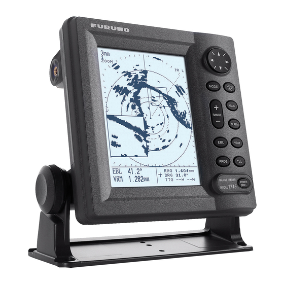
Морской радар Furuno M-1715 предназначен для использования на небольших прогулочных и рыболовных судах, оснащен ярким дисплеем 7 дюймов и компактной сканирующей антенной закрытого типа в обтекателе диаметром 46 сантиметров. Радиолокационная станция предоставляет судоводителю весь арсенал возможностей, которые присущи старшим моделям, включая подавление помех и тревогу охранной зоны. Устройство имеет свидетельство о типовом одобрении Российского Морского Регистра Судоходства, что говорит о его высокой надежности и стабильности работы, что впрочем относится ко всем изделиям компании Фуруно.
Компактность и функционал. Размеры антенны позволяют смонтировать радар даже на небольшом парусном судне, при этом станция обеспечивает обнаружение целей на удалении до 24 морских миль. Монохромный дисплей имеет яркую подсветку и хорошо различим в солнечную погоду, его корпус отвечает стандарту герметичности IPx5 и допускает установку в кокпите или на открытом посту управления. Функциональное оснащение включает весь необходимый набор: сигнализация охранной зоны, EBL (электронная линия азимута), EVRM (электронный изменяемый маркер диапазона), ввод/вывод данных координат курсора, траектория отраженного сигнала, вывод данных TLL (широта и долгота объекта), подавление помех от дождя, отображение путевых точек при наличии GPS данных. Для работы оператора предусмотрено четыре режима: нормальный, сдвиг центра экрана, режим масштабирования и сторожевой режим.
Основные параметры РЛС Furuno M-1715:
- Диагональ экрана 7”, монохромный LCD дисплей 240х320 пикс.
- Сканирующая антенна Фуруно RSB-0095 46 см
- Мощность излучения 2,2 кВт
- Доступно 14 шкал дальности: от 1/8 до 24 миль
- Четыре градации серого цвета
- Три длины и частоты повторения импульсов передатчика
- Автоматическое или ручное подавление помех
- Подавление помех от дождя
- Индикация послесвечения (следов целей)
- Управление курсором и меню посредством Omni Pad
- Четыре режима отображения обстановки
- Электронный пеленг и переменная метка дальности
- Отображение следов целей/эхосигналов с установленным интервалом
- Обозначение путевых точек на экране для упрощения навигации судна
- Настраиваемая сигнализация охранной зоны (на вход и выход целей)
- Пользовательская настройка экрана навигационных данных
- Поддержка внешнего GPS/WAAS приемника
- Обмен данными по протоколу NMEA0183
Комплект поставки Furuno M1715: блок дисплея RDP-142, сканирующая антенна закрытого типа RSB-0095, антенный кабель 10/15/20/30 метров (уточняется при заказе радара), кабель питания 3,5 метра, монтажный комплект, документация, сертификат РМРС (по запросу).
Краткое содержание страницы № 1
MARINE RADAR
MODEL 1715
Краткое содержание страницы № 2
Your Local Agent/Dealer Your Local Agent/Dealer 9-52 Ashihara-cho, 9-52 Ashihara-cho, Nishinomi Nishinomiy ya, Ja a, Jap pan an Tele Telep phone : hone : 0798-65-2111 0798-65-2111 Telefax : Telefax : 0798-65-4200 0798-65-4200 F FIRST EDITION : IRST EDITION : . . 0000 0000 A All ri ll rig ghts reserved. hts reserved. Printed in Japan Printed in Japan PUB.No. PUB.No. OME-35140 OME-35140 *00014791100* *00014791100* *00014791100* *00014791100* ( ( ) ) MODEL1715 MODEL1715 * 0 0 0 1 4 7 9 1 1 0
Краткое содержание страницы № 3
TABLE OF CONTENTS SAFETY INSTRUCTIONS………………………. ii 2. MAINTENANCE, TROUBLESHOOTING….. 18 FOREWORD……………………………………….. iii 2.1 Maintenance …………………………………..18 SYSTEM CONFIGURATION………………….. iv 2.2 Replacing the Fuse………………………….19 EQUIPMENT LISTS………………………………. v 2.3 Troubleshooting ………………………………19 2.4 Diagnostics ……………………….
Краткое содержание страницы № 4
SAFETY INSTRUCTIONS Safety Instructions for the Operator Safety Instructions for the Installer WARNING WARNING ELECTRICAL SHOCK HAZARD ELECTRICAL SHOCK HAZARD Do not open the equipment. Do not open the equipment unless totally familiar with electrical circuits and Only qualified personnel service manual. should work inside the equipment. Only qualified personnel Wear a safety belt and hard should work inside the hat when working on the equipment. antenna unit. Wear a safety belt and hard hat w
Краткое содержание страницы № 5
FOREWORD A Word to the Owner of the Features MODEL 1715 Your radar has a large variety of functions, all contained in a rugged plastic case. All Congratulations on your choice of the controls respond immediately to the FURUNO MODEL 1715 Marine Radar. operator’s command and each time a key is pressed the corresponding change can be For over 50 years FURUNO Electric seen on the screen. Company has enjoyed an enviable reputation for innovative and dependable marine The main feat
Краткое содержание страницы № 6
SYSTEM CONFIGURATION ANTENNA UNIT RSB-0095 DISPLAY UNIT RDP-142 GPS RECEIVER GP-310B/320B MENU MODE ESC GAIN WIND INDICATOR, RANGE SPEED INDICATOR ALARM EBL VRM PROG TLL NAVIGATOR POWER or ECHO SOUNDER BRILL (NMEA 0183) RECTIFIER EXTERNAL PR-62 BUZZER XH3-BZ-L970 SHIP’S MAINS 12-24 VDC : Standard supply SHIP’S MAINS : Optional supply 115/230 VAC, 1φ, 50/60 Hz : Local supply iv
Краткое содержание страницы № 7
EQUIPMENT LISTS Standard supply Name Type Code No. Qty Remarks Antenna Unit RSB-0095 — 1 Display Unit RDP-142 — 1 CP03-25301 008-442-280 1 set For antenna unit, including EMI core CP03-24910 000-080-231 Antenna cable (10 m) Installation CP03-24920 000-080-232 1 set Antenna cable (15 m) Materials* CP03-24930 000-080-233 Antenna cable (20 m) CP03-25101 008-441-250 1 set For display unit, including tapping screws for mounting hanger Spare Parts* SP03-09800 000-085-441 1 set Fuse *
Краткое содержание страницы № 8
1. OPERATION 1.1 Controls Cursor Pad Chooses menu items; adjusts VRM, EBL and cursor. Chooses display mode. MENU MODE Opens/closes menu; ESC escapes from current operation. GAIN Opens dialog box for adjustment of gain, A/C SEA, A/C RAIN. RANGE Chooses radar range. ALARM Enables/disables guard alarm. Turns EBL on/off. EBL VRM Turns VRM on/off. Shortcut key PROG TLL Outputs chosen target’s L/L position to plotter. POWER BRILL How to remove the hard cover Short press: Turns power on. Place your
Краткое содержание страницы № 9
1. OPERATION 1.2 Indications Simulation mode Range TRAIL 1.5nm Echo trails Range ring G(IN) 0.5 Guard alarm (IN or OUT) ES H interval ZOOM Echo stretch IR H WATCH Zoom Interference rejector FTC SIM Rain clutter suppressor Watchman Guard EBL zone Heading line Cursor Range rings VRM Range, Brg Rng Bearing, 8.56 nm 306° XTE (Cross-track error) Course Cse XTE 0.39 nm 155° Trip meter Position Position 34°22.539 N 136°07.516 E
Краткое содержание страницы № 10
1. OPERATION Note 2: The example screens shown in this 1.3 Turning Power On/Off manual may not match the screens you see Press the [POWER/BRILL] key to turn on the on your display. The screen you see depends power. The unit beeps, the startup screen on your system configuration and equipment appears, and then the equipment checks the settings. ROM and RAM for proper operation and displays program number. The ROM and RAM check shows OK or NG (No Good). If 1.4 Transmitting, Standb
Краткое содержание страницы № 11
1. OPERATION Range 1.5 Adjusting Display 6.0 nm 2.0 Range ring Contrast, Brilliance interval 1. With the power turned on, press the [POWER/BRILL] key momentarily to show the brilliance/contrast adjustment window. BRILL/CONTRAST LOW HIGH CONT: 4 RNG 03.2nm EBL — — — .-° BRG 60.2° VRM — — — -nm TTG 02H21M LOW HIGH 9 BRILL: Location of ran
Краткое содержание страницы № 12
1. OPERATION 2. Press ▲ or ▼ to choose AUTO or MANU causing a loss of close-in targets. This dark as appropriate. zone is even more dangerous if the sensitivity has not been properly adjusted. Automatic gain adjustment 1) Press ► to open the automatic gain Always leave a little sea clutter visible on the options window. screen, first adjusting automatically and then ROUGH fine tuning with the manual control as MODERATE necessary. CALM Automatic gain options 2) Press ▲ or ▼ to
Краткое содержание страницы № 13
1. OPERATION Manual A/C SEA adjustment 1.10 Measuring the Range While observing the screen and the A/C The bearing to a target can be measured by SEA tuning bar, press ◄ or ► to adjust the range rings, by the cursor and by the the A/C SEA. The setting range is 0-100. VRM (Variable Range Marker). 4. Press the [MENU/ESC] key to finish. Measuring range by the cursor Operate the cursor pad to place the cursor on
Краткое содержание страницы № 14
1. OPERATION 1.11 Measuring the Bearing 1.12 Shifting the Display The bearing to a target can be measured with Own ship position, or sweep origin, can be the cursor and the EBL (Electronic Bearing displaced manually or automatically to Line). expand the view field without switching to a longer range. The default shift method is Measuring bearing with the cursor manual. Operate the cursor pad to place the cursor on If shift is activated when nav data is displayed, the inside edge of
Краткое содержание страницы № 15
1. OPERATION 1.13 Zoom 1.14 User Menu Overview The zoom feature allows you to double the The User menu, consisting of three pages of size of a selected area. menus, contains 12 items which the user may set according to conditions or preference. If zoom is activated when nav data is displayed, the nav data is automatically 1. Press the [MENU] key to open the User erased. menu. INT REJECTION LOW 1. Use the cursor p
Краткое содержание страницы № 16
1. OPERATION User menu description 1.16 Interference Rejector Item Description Mutual radar interference may occur in the INT Rejects radar interference. vicinity of another shipborne radar operating REJECTION in the same frequency band (9 GHz). It is ECHO Stretches echoes in range seen on the screen as a number of bright STRETCH direction or range and bearing spikes either in irregular patterns or in the direction. form of usually curved spoke-like dotted lines FTC Suppresses lon
Краткое содержание страницы № 17
1. OPERATION 4. Press ▲ or ▼ to choose appropriate time, 1.17 Noise Rejector or OFF to cancel echo trails. “CONTIN.” The noise rejector suppresses white noise, paints trails continuously. which appears on the screen as many dots 5. Press ◄ to close the options window. scattered randomly over the display. 6. Press ▼ to choose TRAIL BRILLIANCE. 7. Press ► to open the options window. 1. Press the [MENU/ESC] key to
Краткое содержание страницы № 18
1. OPERATION How guard zone type is determined 1.20 Guard Alarm After the guard zone has been set, the radar The guard alarm allows the operator to set checks for targets inside the guard zone, the desired range and bearing for a guard which takes about 8 to 12 seconds. When the zone. When ships, islands, landmasses, etc. check is completed, “G(IN)” or “G(OUT)” violate the guard zone, audio and visual replaces G(—) at the top right corner. alarms are released to call your attention
Краткое содержание страницы № 19
1. OPERATION 1.21 Watchman 1.22 Suppressing Long-range Rain Clutter The radar «wakes up» at specified time intervals (5, 10, or 20 minutes) and operates In adverse weather, clouds, rain or snow for 10 scans, the start of which is announced produce spray-like spurious echoes which by releasing the audio alarm. If change is impair target detection over a long distance. found in the guard zone from the previous 10 The
Краткое содержание страницы № 20
1. OPERATION 1.24 Hue ECHO STRETCH OFF The default hue setting (DAY) displays LOW echoes in tones of gray on a white HIGH background, which is most suitable for daytime viewing. For nighttime viewing you Echo stretch options window may reverse this arrangement. 2. Press ▲ or ▼ to choose appropriate option. 1. Press the [MENU/ESC] key to open the 3. Press the [MENU/ESC] key to close the User menu. options window. 2. Press ▲ or ▼ to choose HUE from page 2. Programming the PRO
ГлавнаяБиблиотека # Library Справочники # Handbooks Инструкции к аппаратуре мостика # Bridge Equipment ManualsFuruno РЛС M-1715
< Назад
Вперёд >
Скачать
Последние публикации
-
20 великих стихотворений
-
Encyclopedia of Ship Technology
-
Кодекс безопасной практики размещения и крепления груза (Кодекс РКГ/CSS Code)
-
Техническое обслуживание судового навигационного электро оборудования и приборов
-
Терминологический справочник судоводителя по ведению дел и документации на английском языке
-
Технологии обработки мусора на судах. Инсинераторы
-
Theory and Practices of Marine Pilotage

249 ₽
Инструкция (руководство пользователя) на Морская РЛС FURUNO M-1715
Артикул: furuno-m-1715
Категория: FURUNO
-
Описание
-
Детали
Описание
Инструкцию по эксплуатации FURUNO M-1715 на русском языке можно будет скачать в личном кабинете после оформления и оплаты заказа.
Детали
| Формат файла |
|
|---|---|
| Размер инструкции в кб |
3858 |