-
Contents
-
Table of Contents
-
Bookmarks
Quick Links
18-Channel Digital Proportional R/C System
TM
TM
INSTRUCTION MANUAL
1M23N30202
Related Manuals for FUTABA T18SZ
Summary of Contents for FUTABA T18SZ
-
Page 1
18-Channel Digital Proportional R/C System INSTRUCTION MANUAL 1M23N30202… -
Page 2
TABLE OF CONTENTS INTRODUCTION……….4 …… 46 ……….61 ……..24… -
Page 3
TABLE OF CONTENTS → → → → …………96 …………→ → → → → →… -
Page 4
“off season” to ensure safe operation. programming. Please be sure to regularly visit the T18SZ Frequently Asked Questions web site information on the T18SZ radio system and is updated regularly. Any technical updates and US for the most rapid and convenient response. -
Page 5
You may contact your local recycling center for information on where to return the spent battery. Please call 1-800-8BATTERY for information on Ni-Cd battery recycling in your area. Futaba Corporation involvement in this program is part of its commitment to protecting our environment and conserving natural resources. -
Page 6
against harmful interference in a residential installation. correct the interference by one or more of the following measures: —Reorient or relocate the receiving antenna. —Increase the separation between the equipment and receiver. —Connect the equipment into an outlet on a circuit different from that to which the receiver is connected. -
Page 7: For Safe Use
Use of this product with other than models may be restricted by Export and Trade Control Regulations. 3. Modification, adjustment, and parts replacement: Futaba is not responsible for unauthorized modification, adjustment, or replacement of parts on this product. ■ No part of this manual may be reproduced in any form without prior permission.
-
Page 8
Do not fly at the following places: Always check operation of each control surface and perform a range test before each flying ■ Near another radio control flying field. session. Also, when using the trainer function, ■ Near or above people. check the operation of both the teacher and ■… -
Page 9
■ Charging the battery past the specified value may Insert the power cord plug firmly into the cause a fire, combustion, rupture, or liquid leakage. When receptacle up to its base. quick charging, do not charge the battery above 1C. Always use the charger with the specified ■… -
Page 10: Storage And Disposal Precautions
■ Since the metal parts of the case may corrode, always keep them clean. ■ Futaba is not responsible for damage sustained by combination with other than Futaba Genuine Parts. Use Join the Academy of Model Aeronautics. the parts specified in the instruction manual and catalog.
-
Page 11
2 channels) 2.4GHz dedicated system. Color touch screen LCD T18SZ has a HVGA 4.3inch full color Backlight LCD touch screen. The screen is manufactured of a S.BUS2 system By using the S.BUS2 system multiple servos, gyros and telemetry sensors are easily installed with a minimum amount of cables. -
Page 12
You cannot use the self-neutral throttle stick for R/C airplanes, helicopters, and certain multi- copters. Allowing the engine/motor to reach middle speed via automatic throttle stick return is very dangerous. If using the T18SZ for R/C airplanes and helicopters, you must change the throttle stick to the ratchet type. < Before Use >… -
Page 13
: SBS-01G] [Voltage sensor : SBS-01V] [S.BUS servo sensor : SBS-01S] • Neckstrap — a neckstrap may be connected to your T18SZ system to make it easier to handle and improve • Y-harnesses, servo extensions, hub,etc — Genuine Futaba extensions and Y-harnesses, including a heavy- duty version with heavier wire, are available to aid in your larger model and other installations. -
Page 14
● Monitor LED ● Antenna ● Carrying handle ● Dial LD.RD ● Switch ● Switch SA.SB.SE.SF SC.SD.SG.SH ● Slide lever ● Slide lever ● Stick ● Stick ● Power Switch ● Digital trim T1 ∼ T6 ● Hook ● HOME/EXIT Button ●… -
Page 15
As with all radio frequency transmissions, the strongest area of signal transmission is from the sides of the transmitter’s antenna. As such, the antenna should not be pointed directly at the model. If your If you fly with your Low power transmitter facing the model at the angle shown in the illustration,… -
Page 16
SF : SH : 2 positions; Alternate; 2 positions; Momentary; Long lever Long lever SE : SG : 3 positions; Alternate; 3 positions; Alternate; Short lever Short lever SA : 3 positions; Alternate; SD : 3 positions; Alternate; Short lever Short lever SB : 3 positions;… -
Page 17
The Linear Slider LS and RS offer analog input. *The T18SZ transmitter beeps when the lever comes to the center. *You can select a slide lever and set the movement direction on the setting screen of mixing functions. -
Page 18
This transmitter is equipped with 6 digital trims. Each time you press a trim button, the trim position moves one step. If you continue pressing it, the trim position starts to move faster. In addition, when the trim position returns to the center, the tone will change. -
Page 19
This 2P connector connects FT2F2100B V2 to the transmitter. LiFe Battery The balance charge connector is not connected ① A side battery cover when the battery is installed in the transmitter. is opened. *This connector is used when charging with the LBC-4E5, which is sold separately. -
Page 20
* If there is any problem, the message «Backup Error» will be shown the next time when you turn on the power of the transmitter. Do not use the transmitter as it is. Send it to the Futaba service center. WARNING Never plug the charger into an outlet other than the indicated voltage. -
Page 21
When turning on the power, the T18SZ transmitter will begin emitting RF automatically after it part of the front of a T18SZ. *If THR stick is high, a WARNING screen will appear. Another warning will appear if a power supply is attached. (In Multicopter mode, the THR position alarm will not appear.) -
Page 22
Tapping the settings buttons for Tap the panel with your finger to enter each value on the settings screen data. will cause value input buttons to appear at the top of the panel. be careful so that you don’t scratch the Touch Panel Pressing and holding a value will push the Touch Panel with excessive force or drop return it to its default setting. -
Page 23: Panel Lock
CAUTION The T18SZ’s touch screen is very sensitive. To avoid accidentally activating it during a flight, it is suggested that it be locked. Due to the touch screen’s sensitivity, allowing it to be touched…
-
Page 24
The status of the transmitter is displayed by LED at the upper part of the front of a T18SZ. A Test mode Light lue light A T mode reen light mode ellow green light iolet light tarting ed light Trainer tudent… -
Page 25
*Example Stick Mode2 A general model example. (There is also a different operational model.) Roll Axis Control Pitch Axis Control Right roll Nose Up The right aileron is up. Elevator stick The left aileron Aileron stick is down. To the right (moved to the bottom) Elevator is Level flight… -
Page 26
*Example Stick Mode2 A general model example. (There is also a different operational model.) Roll Axis Control Pitch Axis Control Right roll Nose Up Elevator stick Aileron stick To the right (moved to the bottom) Level flight Level flight Neutral Neutral Left roll Elevator stick… -
Page 27
*Example Stick Mode2 A general model example. (There is also a different operational model.) Roll Axis Control Pitch Axis Control Right roll Nose Up Right slide Elevator stick Aileron stick Back slide To the right (moved to the bottom) Hovering Level flight Hovering Level flight… -
Page 28
sticks in line with your hand size. Stick head Stick head Side cover 1. Hold the lever head » » and turn the lever 3. Using your hand remove the transmitter’s rear head «A» counter clockwise. The lock will be rubber grips. -
Page 29
•Stick Tension (J4) (Mode 1/2) a stick lever either inwards or outwards from the •Stick Tension (J1) (Mode 1/2) center stick position. 1.5mm hexagonal wrench •Stick Tension (J3) (Mode 1) •Stick Tension (J2) (Mode 2) 1.5mm hexagonal wrench Turn screw counter-clockwise. Turn screw clockwise. -
Page 30
You can choose either airplane ratchet system or helicopter-touch. *This transmitter has two ratchet plates, one for airplane and the other one for helicopter. If you tighten both screws, you won’t be able to *If you want to change the setting from airplane to helicopter (or from helicopter to airplane), turn the ratchet screw clockwise until the throttle stick moves freely. -
Page 31
The T18SZ transmitter model data can be stored by using any commonly found SD card. When T18SZ transmitter update software is released, the software is updated using an SD card. The T18SZ is capable of using SD cards with a memory size between 32MB and 2GB. -
Page 32
When using an S.BUS servo and telemetry sensor, connect them both here. Earphone Connecting a stereo headphone to this plug, the Plug speech information of telemetry can be heard. Charge Plug This is the connector for charging the LiFe battery FT2F2100BV2 that is installed in the transmitter. -
Page 33
DANGER Before using the receiver, be sure to read the precautions listed in the following pages. Don’t attach a connector as shown in the preceding illustration. *It will short-circuit if connected in this way. A short circuit across the battery terminals may cause abnormal heating, fire and burns. -
Page 34
Link button for more than 2 seconds. 6. Once locked into the correct mode the LED will change to a solid color. The T18SZ has the ability to link to two 7. Please cycle the receiver(s) power off and R7008SB receivers. One of them outputting… -
Page 35
The R7008SB has two antennas. In order to maximize signal reception and promote safe modeling Futaba has adopted a diversity antenna system. This allows the receiver to obtain RF signals on both *Must be kept as straight as possible. Antenna… -
Page 36
Wood screw 2.3-2.6mm nut washer Rubber Rubber WARNING grommet grommet Brass eyelet Brass eyelet Servo mount Connecting connectors Servo mount 2.3-2.6mm screw Be sure to insert the connector until it stops at the deepest point. (Airplane/Glider) (Helicopter) How to protect the receiver from vibration and water To prevent the servo lead cable from being Wrap the receiver with something… -
Page 37
even with models that use a large number of servos. In addition, the wings can be quickly installed to the fuselage without any erroneous wiring by the use of only one simple wire, even when there are a large number of servos used. S.BUS Glider usage example Receiver: R7008SB Servo: S3174SV×9 ( Optional ) -
Page 38: Power Supply
*When using 8/SB as S.BUS, you must set the receiver to Mode B or Mode D. See ●S.BUS Servo R7008SB CH MODE TABLE Since the channel number is memorized by the S.BUS itself, any connector can be used. When the SBD-1, SBD-2 (sold separately) Receiver is used, ordinary servos can be used with the S.BUS system.
-
Page 39
When using the S.BUS2 port, an impressive array of telemetry sensors may be utilized. S.BUS2 TABLE S.BUS Servo S.BUS2 Servo Receiver port Telemetry sensor S.BUS2 S.BUS Gyro Gyro S.BUS ○ ○ × S.BUS2 × (※) ○ ○ (※)Don’t connect S.BUS Servo, S.BUS Gyro to S.BUS2 connector. -
Page 40
S.BUS/S.BUS2 servos or a telemetry sensor can be connected directly to the T18SZ. Channel setting and other data can be entered for the S.BUS/S.BUS2 servos or sensors. 1. Connect the S. US device you want to set with as shown in the gure. -
Page 41
This switch ESW-1J connects a Futaba receiver to a battery and is turned on and off in an FET circuit. Compared to using a mechanical switch, it allows more current to be sent with less loss. Receiver Battery The receiver power supply can be connected to any <… -
Page 42: Basic Operation
BASIC OPERATION This is the Home screen and descriptions of its menus. Use your finger to operate the touch screen. Battery voltage for receivers Condition name Battery Indicator • In FASSTest/T-FHSS mode, it is • The condition name • When the battery voltage displayed.
-
Page 43
Each transmitter has an individually assigned, unique ID code. In order to start operation, the receiver must be linked with the ID code of the transmitter to which it is being paired. Once the link is made, the ID code is stored in the receiver and no further linking is necessary unless the receiver is to be used with another transmitter. -
Page 44
setup a «Rx1» and «Rx2» in the «dual» mode. 9. ACT will be chosen if telemetry is used. It is INH when not using it. *Telemetry function cannot be used for the 2nd receiver. → FASSTest18CH *Telemetry function cannot be used for the dual mode. -
Page 45
◆ When the receiver has the transmitter’s ID in memory, a link is established and normal operation is allowed. ◆ When the transmitter has the receiver’s ID in memory, a link is established and telemetry functions are usable. The transmitter stores receiver IDs by model; thus, if it does not have a particular receiver model ID stored in memory or has a different receiver ID stored, telemetry functions will be unusable. -
Page 46
«HOME/EXIT» button. NEVER start flying when the «Range check mode» is active. Should you require additional time to perform a range 3. T18SZ Power ON. check, highlight Restart before your time expires and tap 4. Select «Range check» at the System menu. -
Page 47
MODEL BASIC SETTING PROCEDURE Initial setting assigns 1 model to the T18SZ transmitter. The Model Select function is used to add models and to select models which are already set. If the direction of the servo is incorrect, adjust the direction with the Reverse function of the Linkage menu. -
Page 48
This function is used when an air brake is necessary when taking off or diving, etc. offset amount can be activated by a switch. The offset amount of the aileron, elevator, and flap servos can be adjusted as needed. Also the speed of the aileron, elevator, and flap servos can be adjusted. -
Page 49
Default setting assigns 1 model to the T18SZ. To add new models or to call a model already set, use the Model per model. select function. The Condition select function automatically allocates This is convenient when calling a model after (General setting) registering the model names in advance. -
Page 50
For a description of the connection method, see «Servos connection by model type». Note: The channel assignment of the T18SZ is different from that of our existing systems. Swash plate correction (Except H-1 mode) -
Page 51
matched to airborne ight. Set to -7º~ 12º as standard. *If throttle hold is necessary, please refer to the Throttle hold Pitch curve (Idle up 2) function. The high side pitch setting is less than idle up 1. The standard is +8º. Pitch curve (Hold) Throttle cut provides an easy way to stop the engine, At auto rotation, use the maximum pitch at both… -
Page 52
The T18SZ transmitter channels are automatically assigned for optimal combination according to the type selected with the Model type function of the Linkage menu. The channel assignment (initial setting) for each model type is shown below. Connect the receiver and servos to match the type used. -
Page 53
1AIL 2AIL 2AIL+1FLAP 2AIL+2FLAP 2AIL+4FLAP 4AIL+2FLAP 4AIL+4FLAP Airplane Glider Airplane Glider Airplane Glider Airplane Glider Airplane Glider Airplane Glider Airplane Glider Aileron Aileron Aileron Aileron Aileron Aileron Aileron Aileron Aileron Aileron Aileron Aileron Aileron Aileron Elevator Elevator Elevator Elevator Elevator Elevator Elevator Elevator… -
Page 54
2AIL 2AIL+1FLAP 2AIL+2FLAP 2AIL+4FLAP 4AIL+2FLAP 4AIL+4FLAP Airplane Glider Airplane Glider Airplane Glider Airplane Glider Airplane Glider Airplane Glider Aileron Aileron Aileron Aileron Aileron Aileron Aileron Aileron Aileron Aileron Aileron Aileron AUX4 AUX4 AUX4 AUX4 AUX4 AUX4 Aileron2 Aileron2 Aileron2 Aileron2 Aileron2 Aileron2 Throttle… -
Page 55
2AIL 2AIL+1FLAP 2AIL+2FLAP 2AIL+4FLAP 4AIL+2FLAP 4AIL+4FLAP Airplane Glider Airplane Glider Airplane Glider Airplane Glider Airplane Glider Airplane Glider Aileron Aileron Aileron Aileron Aileron Aileron Aileron Aileron Aileron Aileron Aileron Aileron Rudder2 Rudder2 Rudder2 Rudder2 Rudder2 Rudder2 Aileron2 Aileron2 Aileron2 Aileron2 Aileron2 Aileron2 Throttle… -
Page 56
H-4/H-4X Swash All other Aileron Aileron Elevator Elevator Throttle Throttle Rudder Rudder Gyro Gyro Pitch Pitch Governor Governor Elevator2 Governor2 Gyro2 Gyro2 Gyro3 Gyro3 Governor2 Needle Needle AUX5 AUX4 AUX3 AUX2 AUX1 H-4/H-4X Swash All other Aileron Aileron Elevator Elevator Throttle Throttle Elevator2… -
Page 57
Multicopter Aileron Elevator Throttle Rudder Gyro Gyro2 Gyro3 Camera TILT Camera PAN Camera REC Mode AUX5 AUX4 AUX3 AUX2 AUX1 SW SH SW SH SW SA SW SA < Model Basic Setting Procedure >… -
Page 58
SYSTEM MENU When the System menu button is tapped, The System menu sets up functions of the the menu shown below is called up. Tap the transmitter. This does not set up any model data. function button that you want to enter. Return to Home screen [Display]: Display adjustment. -
Page 59
Display The following LCD screen adjustments: Backlighting brightness adjustment Backlighting decrease time adjustment Touch screen calibration Tap the [Display] button in the System menu to call the setup screen shown below. Return to System menu Backlight max. brightness adjustment Touch calibration 1. -
Page 60
Date and Time This function adjusts the system clock of the The system timer can also be reset. T18SZ transmitter. Perform this setting when you *The system timer is displayed on the Home screen. purchase the set and when adjustment is necessary. -
Page 61
Calibration Usually, this calibration is unnecessary. Please perform this calibration only if a change at the center of a stick should arise after prolonged use. Tap the [Calibration] button in the System menu to call the setup screen shown below. Return to System menu How to Calibrate 1. -
Page 62
Low battery alarm voltage set Battery Select the battery alarm voltage according to the battery to be used. It isn’t indicated in case of manual setting. Return to System menu Battery type change : LiFe(2cells) → NiMH(5cells) → Manual setting When choosing manual setting, the numerical value can be input. -
Page 63
An S.BUS(2) servo can memorize the channel and various settings you input. Servo setting can be performed on the T18SZ screen by wiring the * With some S.BUS(2) servos, there are some functions which cannot be used. If a function cannot be used, the display S.BUS/S.BUS2… -
Page 64
S.BUS Servo Description of function of each parameter *There are functions that can and cannot be performed according to the servo type. • ID Displays the ID of the servo whose parameters are to be read. It cannot be changed. •… -
Page 65
• Boost ON/OFF OFF : It is the boost ON at the time of low-speed operation.(In the case of usual) ON : It is always the boost ON.(When quick operation is hope) • Damper The characteristic when the servo is stopped can be set. When smaller than the standard value, the characteristic becomes an overshoot characteristic. -
Page 66
Information language and Unit system used by the system can also be changed. The Information screen displays the T18SZ This function registers the T18SZ user name system program version information, SD card and the language displayed at proportional can be (memory size, card free size) information. -
Page 67
LINKAGE MENU The Linkage menu is made up of functions which perform model addition, model type selection, end point setting, and other model basic settings. Tap the [Linkage menu] button in the Home screen to call the setup screen shown below. Select the function name and return to the Home screen. -
Page 68
Servo Test Graph Display / Displays servo positions. Servo monitor This is used for testing servo movement. In order to prevent any potential difficulties, “Moving Test” (repetition mode) and “Neutral the servo test function will be inoperable, or the Servo Test function is not operational if the The “Neutral Test”… -
Page 69
This function is used to load the settings of the screen. desired model into the T18SZ’s memory. The Copy function is used to copy one set The settings may be selected from either the of model data into a second memory within the transmitter’s built-in memory or a SD card (32MB-… -
Page 70
Model call Model deletion 1. Tap the Internal or SD card. Select the 1. Tap the select model name or the model you location to which the desired model is to be want to delete in the model list. saved. (The model currently selected cannot be deleted.) 2. -
Page 71
Model name change Model copy 1. The model data chosen at current model 1. The model data chosen at current model can be changed. The current model name, can be copied. The current model name, tap. tap. 2. When [Rename] is tapped, a keyboard appears on the screen. -
Page 72
This function selects the model type from among airplane, glider, Model type helicopter, and multicopter. Note: The Model Type function automatically selects the appropriate output channels, control functions, wing) and three types of tail wings are available and mixing functions for the chosen model type. for airplanes. -
Page 73
Set the type you choose by tapping Airplane/Glider : Choose the Helicopter : Choose the wing type and tail. swash type. < Linkage menu >… -
Page 74
Use to reverse the servo throw direction. Servo Reverse Servo Reverse changes the direction of an individual servo’s response to a control stick model memory, hook ups, and radio function. movement. WARNING For CCPM helicopters, be sure to read the section on Swash AFR before reversing any servos. -
Page 75
Sets the travel, limit point. End point The End point function adjusts the left and right servo throws, generates differential throws, and will correct improper linkage settings. 30 ∼ 30 ∼ 140% 140% The travel rate (normal full stick movement at high rates) can be varied from 30% to 140% in each direction on channels 1 to 16. -
Page 76
Sets the speed of each servo. Servo speed The Servo speed setting is used to set the servo speed setting can be varied from 0 to 27 in each delay for each channel, from channel l to channel channel. 16. The system uses the programmed speed (delay) to slow down servo position changes. -
Page 77
Channel assignment for each function can be changed to suit your needs. Function DG1, DG2 (switch channels) When you select model and wing (swash) types, you will find that the optimized combinations of These two channels can be used as switch (On/ servo output channels and functions have been Off) channels. -
Page 78
Trim change 1. Tap the trim button to call the trim setup screen. H/W reverse This function reverses the operation signal of the 2. The following items can be set at the trim sticks, switches, trimmer levers, and knobs. setup screen. Hardware setting (Selection of switch, etc. -
Page 79
For safety, always set the fail safe functions. either mode for each channel. ■ Especially set the throttle channel fail safe function The T18SZ system also provides you with so that the servo moves to the maximum slow side an advanced battery monitoring function that… -
Page 80
System Type selection Dual receiver function (only FASSTest 18CH / T-FHSS mode) The T18SZ is for 2.4GHz only. The system can be changed from among 6 choices: FASSTest Dual receivers can be linked with the T18SZ. 18CH, FASSTest 12CH, FASST MULTI, FASST Two receivers are recognized individually by ID 7CH, T-FHSS, S-FHSS. -
Page 81
The example for choosing System Type -Want to use a -Want to use an miniature receiver T-FHSS system -Response speed has -Want to use a -Want to use an for indoor planes receiver priority over number previously used S-FHSS system of channels receiver as is miniature receiver… -
Page 82
Digital trim settings T1-T6 setting (Trim) This function adjusts the digital trim’s control When the flight conditions are set, the trim step amount and operation mode (T1-T6.) operation can be coupled with among all the conditions which combination mode is selected. Select [T1-T6 setting] at the linkage menu and call the setup screen shown below. -
Page 83
Stops the engine safely and easily. Throttle cut Throttle cut provides an easy way to stop the idle. The action is not functional at high throttle to avoid accidental dead sticks. The switch’s location and direction must be chosen, as it defaults to » − Tapping this will change −… -
Page 84
Lowers the engine idling speed. Idle down The Idle down function lowers the engine’s idle The action is not functional at high throttle to avoid accidental dead sticks. The switch’s location and direction must be chosen, as it defaults to » −− » . Select [Idle down] at the linkage menu and call the setup screen shown below. -
Page 85
Limits the swash travel within a xed range to prevent linkage damage Swash ring (Helicopter only) This function limits the travel of the swash plate to prevent linkage damage as the aileron and elevator operation is used. It is useful for 3D heli setting. -
Page 86
Swash operation linkage correction function (helicopter only, except Swash swash type H-1). Neutral Point Mixing Rate At your linkages, if the servo horn deviates from a perpendicular position at neutral, the linkage the tendency of the swash-plate for each control. compensation functions in this menu may not compensate effectively. -
Page 87
Linkage correction setting procedure Neutral point setting procedure *Becomes the compensation reference point. rate. *Adjusting the servo horn so that the neutral point position is *This function compensates for elevator interference 1. Hold the servo horn at a right angle to the by aileron operation or aileron interference by linkage rod, and then tap the [Enter] button elevator operation at Low pitch and Hi pitch at… -
Page 88
Stick alarm An alarm (single beep) can be sounded at the Alarm function ON/OFF can be set by switch. Tapping this will change INH to ON and activated. If the throttle stick Return to Linkage menu reaches the yellow l i n e , a n a l a r m w i l l sound. -
Page 89
Timer setting Timer The Timer function may be set for Each timer may be set for count-down or count up any desired time, i.e. engine run time, operation with a target time. specified times for competitions, etc. If a target time is set and the timer reaches the set time, a Two independent timers are provided buzzer sound for each count is generated. -
Page 90
Function name can be changed Function name can be changed for the full name (10 characters) or for the abbreviated name (4 characters). Tap the [Function name] button in the Linkage menu to call the setup screen shown below. Return to Linkage menu Function name change method 6. -
Page 91: Home Display
P.98 voltage. Using various optional Optional telemetry sensors are necessary. P.92 telemetry sensors. T18SZ setting is unnecessary. Using several telemetry Setting by «sensor» in the menu is necessary. P.94 sensors of the same type. (Register is necessary.) Setting alarms from the Setting by «Telemetry»…
-
Page 92
Home display HOME/EXIT is pushed 4 of telemetry data is displayed *Be aware that pressing and holding this activates the key lock Y o u c a n c h o o s e which type of sensor t o d i s p l a y f o r f o u r displays. -
Page 93
Various telemetry sensors setting Sensor [What is a slot?] This screen registers the telemetry sensors used Servos are classified by CH, but sensors are with the transmitter. When only one of a certain classified in units called “slot”. There are slots type of sensor is used, this setting is unnecessary from No. -
Page 94
T18MZ/T14SG. Reading all the sensors to be used 1. Connect the sensor to the T18SZ as shown in the gure above. 2. Tap Reload on page 3/3 of the [Sensor] screen. 3. Tap Reload . -
Page 95
*For some transmitters (e.g., T6K), when the start slot of a sensor is changed, the sensor cannot be used. Sensor slot change 1. Connect the sensor to the T18SZ as shown in the gure above. 2. Tap Change slot on page 3/3 of the Sensor screen. -
Page 96
Displaying data from the receiver Telemetry This screen displays your choice of data from the receiver. Also warnings can be activated regarding the user can be warned by an alarm (and vibration). T a p p a g e b u t t o n t o Tap the [Telemetry] button in the Linkage menu to advance to next page. -
Page 97
Displaying data from the Telemetry: Receiver [Battery] receiver battery voltage In this screen, the battery voltage of a receiver is *It cannot be used in FASST mode and S-FHSS mode. displayed. *Only receiver voltage and EXT voltage can be used in FASSTest12CH mode. -
Page 98
Displaying data from the EXT Telemetry: Receiver [Ext. battery] battery voltage port *CA-RVIN-700 must be installed in the aircraft. The EXT-VOLT screen will display the data from You will be alerted by an alarm or vibration if the EXT-battery output from the R7008SB receiver. In order to use this function, it is necessary to *It cannot be used in FASST mode and S-FHSS mode. -
Page 99
Displaying data from the temperature Telemetry : Temperature *A temperature sensor must be installed in the aircraft. Temperature is a screen which displays/sets *It cannot be used in FASST mode and S-FHSS mode. up the temperature information from an optional *Only receiver voltage and EXT voltage can be used in FASSTest12CH mode. -
Page 100
Displaying data from the rpm Telemetry : RPM Sensor *A rpm sensor must be installed in the aircraft. The RPM Sensor screen is used to set up an optional rpm sensor and display the rotation *It cannot be used in FASST mode and S-FHSS mode. information it transmits. -
Page 101
Displaying data from the altitude Telemetry : Altitude *An altitude sensor or GPS sensor must be installed in the aircraft. Altitude is a screen which displays / sets up the altitude altitude from atmospheric pressure. Atmospheric pressure information from an optional altitude sensor or GPS sensor. will get lower as you go up in altitude. -
Page 102
*An altitude sensor or GPS sensor must be installed in the aircraft. VARIO is a screen which displays / sets up the status, the T18SZ incorporates a different melody variometer information from an optional altitude for ascent and descent. Additionally, depending sensor or GPS sensor. -
Page 103
Displaying data from the receiver battery voltage Telemetry: Voltage [Battery] *SBS-01V must be installed in the aircraft. In this screen, the battery voltage is displayed. In this screen, the battery voltage of a receiver is In order to use this function, it is necessary to displayed. -
Page 104
Di sp la yi ng dat a f ro m t he EXT Telemetry: Voltage [Ext. battery] battery voltage port *SBS-01V must be installed in the aircraft. In this screen, the EXT battery voltage is displayed. In order to use this function, it is *It cannot be used in FASST mode and S-FHSS mode. -
Page 105
Displaying data from the Distance Screen Telemetry : GPS [Distance] *A GPS sensor must be installed in the aircraft. The Distance screen displays and sets altitude *The GPS sensor is necessary, and is sold separately. Mount d a t a f r o m a n S B S — 0 1 G G P S S e n s o r ( s o l d and connect the sensor in accordance with the sensor separately), and allows the distance to the airborne instruction manual. -
Page 106
First, the set of a reference is required. Setting a «too close» alarm distance 1. The model and transmitter to which the GPS 1. Tap Alarm and choose from Bu er, Voice, sensor was connected are turned on. and Inhibit. 2. -
Page 107
Displaying data from the speed Telemetry : GPS [Speed] *A GPS sensor must be installed in the aircraft. The speed screen displays and sets the speed data from an SBS-01G (GPS sensor) sold separately. *The GPS sensor is necessary, and is sold separately. Mount and connect the sensor in accordance with the sensor instruction manual. -
Page 108
Telemetry : GPS [Altitude, Variometer, Position] *A GPS sensor must be installed in the aircraft. The Altitude, Variometer, Position screen *It cannot be used in FASST mode and S-FHSS mode. displays and sets the data from an SBS-01G (GPS *Only receiver voltage and EXT voltage can be used in FASSTest12CH mode. -
Page 109
Telemetry : Servo sensor [Current] *Servo sensor must be installed in the aircraft. The SBS-01S can monitor and display the in-flight current, operating angle, and internal temperature of up to two S.BUS2 servos. If you forget to connect the servo wiring during fuselage assembly, or the servo was disconnected, an alarm can be activated at the transmitter. -
Page 110
Telemetry : Servo sensor [Temperature] [Angle] *Servo sensor must be installed in the aircraft. Select [Servo sensor] in the Telemetry screen and access the setup screen shown below. Return to Linkage menu ● Temperature ↑ An upward arrow indicates the alarm will sound when the temperature reaches above your set value. -
Page 111
■ Extension FLD: Log data file *When copying or moving a log file, always select both the .FLI file and .FLD file. Log files can be converted to CSV format by using the telemetry log converter available at the Futaba website. ■ Notes ◇… -
Page 112
When the Instructor activates the trainer switch, PPM. the student has control of the aircraft (if MIX/ If being used as the student, T18SZ can be connected to FUNC/NORM mode is turned on, the Instructor the instructor’s transmitter which requires the student’s mode to be PPM. -
Page 113
«16/12/8 CH»: When the student uses the «16/12/8 CHANNEL»: When the student uses T18SZ,T14SG,T18MZ, select [16CH]. When the the T18SZ (including the T18MZ, T14SG)select student uses the T14MZ, T12Z, T12FG or FX-40, [16CH]. Otherwise select [12CH]or[8CH]. select [12CH]. Otherwise select [8CH]. -
Page 114
3. Select the operating mode for each channel. Trainer student channel setting function In training mode, the instructor’s transmitter can pick up the student’s signal on both the «Function» two transmitters to connect even if the student and instructor have set up their transmitters differently. *When the instructor’s transmitter mode is set to «NORM», the signal of the same channel of the student’s transmitter is output as is. -
Page 115
Mixing warning normal reset Warning setting The warning display at power ON can be turned ON/OFF for each function. Use by setting functions which may be dangerous if operated at power ON to ON. Initial setting is all ON (Buzzer). Tap the [Warning setting] button in the Linkage menu to call the setup screen shown below. -
Page 116
User menu setting *Any change made to data entered from the User menu or T18SZ has a menu for each of the following: from the normal method of use are the same. Changes made System, Linkage, and Model. Also, you can in either way are saved into the transmitter memory. -
Page 117
Model memory setting data reset. (by item) Data reset This function is designed to allow you to reset Model menu setting: selected portions or all of the settings saved in Resets all the functions in the Model menu the active model memory. You may individually choose to reset the following sets of data: All model setting: T1~T6 (All condition):… -
Page 118
Select function to add flight conditions. (Up to 8 and other functions common to all model types. conditions can be used) Note: The T18SZ is designed so that the airplane and Before setting the model data, use the Model glider model types are compatible with aircraft of Type function of the Linkage menu to select the similar type wings. -
Page 119
Flight condition’s addition, deletion, copy, condition renaming, Condition select and condition delay can be set. [All model types] when there are sudden changes in the servo The functions in the Model menu can be used by positions and when there are variations in switching the settings of up to 8 flight conditions the operating time between channels during condition switching can be suppressed. -
Page 120
Currently selected condition name The ON/OFF switch of Conditions List condition is chosen. 1. Tap the [Copy] button. The Copy screen 1 . S e l e c t t h e c o n d i t i o n b y appears. -
Page 121
The angle and curve of each operation function can be set. [All model types] Operation curve adjustment: Three types AFR function is used to adjust the throw and of curves (EXP1, EXP2, and Point) can be operation curve of the stick, lever, and switch selected. -
Page 122
Dual rate D/R curves which can be switched by switch, etc. can be added. The curve can be adjusted by the AFR function. Up to 6 rates can be added for each condition. D/R is set for each condition and is not re ected at other conditions. -
Page 123
Program mixing which can be freely customi ed. Up to 10 Prog. mixes mixings can be used for each condition. [All model types] Offset-type mixing applies a fixed offset or Programmable mixing may be used to correct preset to the programmed channel servo operation undesired tendencies of the aircraft, and it may also and may control up to four circuits simultaneously. -
Page 124
Trim mode ON/OFF setting 1. To turn the trim mode ON/OFF, tap the Trim Group/single mode selection button on the screen. Activating functions for only the selected conditions: *When mixing includes master side trim, set the Trim button to [ON]. When mixing does not include master side trim, set 1. -
Page 125
Model menu functions section. First use (Up to 8 conditions can be used) Note: The T18SZ is designed so that the airplane and the Model type function of the Linkage menu to glider model types can handle aircraft of the same preset the model type, wing type, and tail type wing type. -
Page 126
Camber mixing This mix adjusts the camber and corrects the This function is used when airbrakes are necessary when landing or when diving, etc. during flight. elevators. [Airplane/glider, 2 ailerons or more] [Airplane, general] This mix is used to correct operation of the airbrakes (spoilers) when landing. -
Page 127
[Airplane/glider, 2 ailerons or more] Ail diff. The left and right aileron differential can be adjusted independently. The differential rate can also be adjusted according to the flying state by AIL1 AIL 2 (Main Aileron) (Main Aileron) AIL 3 AIL 4 (Chip Aileron) (Chip Aileron) Select [Ail diff.] at the model menu and… -
Page 128
[Corresponding model type]: Airplane/ Flap setting glider, 2 aps or more] The up/down travel of each flap (camber flaps: FLP1/2, brake flaps: FLP3/4) can be adjusted independently at each servo according to the wing type. The operation reference point of each ap can be FLP 4 FLP 3 offset… -
Page 129: Table Of Contents
[Corresponding model type]: Airplane/ Ail → Camber flap glider, 2 ailerons + 2 aps or more This mix operates the camber flaps (FLP1/2) in the aileron mode. When the aileron stick is manipulated, the ailerons and camber flaps perform aileron operation simultaneously and the operation characteristic of the roll axis is FLP 1 FLP 2…
-
Page 130
[Corresponding model type]: Airplane/ Ail → Brake flap glider, 4 aps or more This mix operates the brake flaps (FLP3/4) in the aileron mode. When the aileron stick is manipulated, the aileron and brake flaps perform the aileron operation simultaneously FLP 4 FLP 3 (Brake Flap) -
Page 131: A Mixing Curve Can Be Set
[Corresponding model type]: Ail → Rudder Airplane/glider, general Use this mix when you want to mix the rudders with aileron operation. A mixing curve can be set. AIL1 AIL 2 Mixing during ight can be turned ON/OFF by (Main Aileron) (Main Aileron) AIL 3 AIL 3…
-
Page 132: Tap [Inh]. (On Is Displayed.) When Setting A Switch, Tap The [—] Item Of
[Corresponding model type]: Airplane/glider, 2 ailerons or more Ele → Camber This function is used when you want to mix the A mixing curve can be set. Mixing during ight can be turned ON/OFF by be increased. setting a switch. (Always ON at [—] setting) The mixing rate can be ne-tuned by setting a VR.
-
Page 133
[Corresponding model type]: Airplane/glider, 2 ailerons or more Camber mixing The up/down side rates of the aileron, ap, and elevator servos can be adjusted by curve. When This function adjusts the rate of camber the mixing direction is reversed by the linkage, operation which operates the wing camber adjustments can be made by changing the (ailerons, camber flaps, brake flaps) in the… -
Page 134
(Curve/rate setup screen) Tap [INH]. The curve and rate are adjusted by calling (ON is displayed.) the aileron, flap, and elevator curve/rate When setting a switch, tap to the [—] item screens. of the switch and tap the screen to call the The rate and curve of each servo can be set selection screen, and then select the switch by calling each screen. -
Page 135
[Corresponding model type]: Airbrake → ELE Airplane/glider, general AIR BRAKE This mix is used when you want to mix the elevators with airbrake (spoiler) operation. It raises the elevators to correct for dropping of the nose during airbrake operation. AILVATOR V-TAIL *This function does not operate when airbrake is not assigned at the Function menu in the Linkage menu. -
Page 136: Flp 1
[Corresponding model type]: Airplane/ Camb.FLP → ELE glider, 2 ailerons + 1 ap or more This mixing is used to correct changes (elevator FLP 1 FLP 2 The elevator servos up side/down side rate can be (Camber Flap) (Camber Flap) adjusted.
-
Page 137: Ail1 Ail
[Corresponding model type]: Rudder → Aileron Airplane/glider, general This function is used when you want to mix the ailerons with rudder operation. It is used when rudder is applied during roll maneuvers, AIL1 AIL 2 (Main Aileron) (Main Aileron) knife edge, etc. of stunt planes. It can be used to AIL 3 AIL 3 (Chip Aileron)
-
Page 138
[Corresponding model type]: Airplane, general Rudder → Elevator Link can be set: Links this mixing to other mixings. This function is used when you want to mix The mixing rate can be ne-tuned by setting a VR. elevator operation with rudder operation. It is used (Fine tuning) to correct undesirable tendencies when rudder is applied in roll maneuvers, knife edge, etc. -
Page 139
[Corresponding model type]: Glider, 2 ailerons or more Butterfly Mixing during ight can be turned ON/OFF by This function allows powerful brake operation setting a switch. (Always ON at [—] setting) by simultaneously raising the left and right The butter y operation reference point can be ailerons and lowering the flaps (camber flap, offset. -
Page 140: Ail 3
(Elevator correction rate setup screen) Overall adjustment by Rate A and Rate B Mixing curve setting *For a description of the curve setting method, see the description at the back of this manual. FLP 4 FLP 3 (Brake Flap) (Brake Flap) FLP 1 FLP 2 (Camber Flap)
-
Page 141
[Corresponding model type]: Glider, general Trim mix 1/2 These functions call the ailerons, elevators, and Example 1. Move to the [INH] item Set the trim mix function to [ON]. The amount of ailerons, elevator, and flaps *When separating the settings for each condition, move to the [Group] item and set it to [Single]. -
Page 142: Adjustment Of Each
[Corresponding model type]: Airplane, general Snap roll Mode: [Master] This function selects the switch and rate Safety SW: [SW-G] (Safety measure) adjustment of each rudder, (ailerons, elevators, or M a s t e r S W : [ S W — H ] ( M a i n s w i t c h f o r Four snap roll directions can be set.
-
Page 143
Air brake This function is used when an air brake is necessary when landing or diving, etc. Elevator The preset elevators and flaps (camber flap, Aileron 2 brake flap) offset amount can be activated by a switch. Aileron 1 The offset amount of the aileron, elevator, and flap servos can be adjusted as needed. -
Page 144
Tap to the [Rate] item. Adjust the rate. When using this function, Tap [INH]. When a Futaba GYA gyro is used, when [GY] type is selected, the sensitivity set value is directly read in both the AVCS and Normal modes. -
Page 145
Wing type: Aileron 2 servos mounted fuselage selected (GYA431AIL), (GYA431ELE), (GYA430RUD), : at 5CH → Gyro 7CH → Gyro2 8CH → Gyro3 Control and Trim → «—» the Function menu of the Linkage menu. Gyro setting of the Model menu. Rate Type Switch… -
Page 146: Adjustments Can Be Made By Changing The Mixing Rate
[Corresponding model type]: Airplane/glider, Tail type Ailevator Ailevator (Effective only when 2 servos used at the elevators) T h i s f u n c t i o n i m p r o v e s t h e o p e r a t i n g performance of the roll axis by operating the elevators as ailerons.
-
Page 147
[Corresponding model type]: Glider, general Acceleration Acceleration setting can be performed at only) This setting is divided into elevator setting and camber setting. The setting method is the same. Camber setting sets the acceleration function for Ele to camber mixing. Setting is not performed when Ele to camber mixing is INH. -
Page 148
[Corresponding model type]: Airplane/glider, general Motor The set operation speed operation can be This function lets you set the operation speed activated at initial operation only. (1 time when the motor of a F5B or other EP glider is operation) However, operation can be repeated started by switch. -
Page 149
[Corresponding model type]: Airplane/glider, Tail type V-tail V-Tail This function lets you adjust for left and right rudder angle changes at elevator and rudder operation of a rudder movement as elevators. In addition to each ELEVATOR RUDDER rudder side moving up and down together, each side (RUDDER 2) (ELEVATOR 2) moves in opposite directions when moving as elevators. -
Page 150
[Corresponding model type]: Airplane/glider, winglet(2RUD) Winglet This function adjusts the left and right rudder angles of airplanes with winglets. Winglets are used to improve the efficiency of wingtip vortices. The winglet is a vertical or angled RUDDER 1 Winglet extension at the tips of each wing. at Flying wing Winglets work by increasing the effective aspect RUDDER 2… -
Page 151: Model Menu (Airplane/Glider/Multicopter Functions)
MODEL MENU (Helicopter functions) This section contains information on the Also, add flight conditions at the Condition commands that apply to helicopters only. For Select screen if necessary before setting the model instructions on airplane, glider and multicopter, data at each function. (Up to 8 conditions can be refer to the sections pertaining to those aircraft.
-
Page 152
Pitch curve / Pitch trim *Up to 17 points can be set for the point curve types. This function adjusts the pitch operation curve create a curve, a simple curve can be created by reducing relative to movement of the throttle stick. the number of input points to 3 or 5, and then entering the a curve. -
Page 153
Setting method Group/Single item: When you also want to input the same setting contents at other conditions, perform setting in the group mode. In this case, the same contents are input to the other conditions set in the group mode. When you want to set each condition independently, select the single mode (initial setting). -
Page 154
The hovering pitch, low pitch, and high pitch trim setup screen can be called from the Pitch curve setup screen. Return to Model menu Hovering pitch trim Low/high pitch trim setting setting Hovering pitch trim High Pitch/Low Pitch Trim The Hovering Pitch trim function trims the pitch High Pitch/Low Pitch Trim is the pitch servo near the hovering point. -
Page 155
Throttle curve / Throttle Hover trim This function adjusts the throttle operation curve point data is used, a simple curve can be easily for each condition for optimum engine speed to created by reducing the number of input points of throttle stick movement. -
Page 156
Curve setting examples created by reducing the number of points on the The curves shown below are created by using line to 5. When actually creating a curve, enter the point curve type and inputting the data of the 5 points 0% (low side), 25%, 50% (center), 75%, value). -
Page 157
Acceleration This function is used to adjust the pitch and the throttle rise characteristic at acceleration/ deceleration operation. An acceleration function which temporarily increases the pitch and throttle operations at throttle stick acceleration/deceleration operation can be set. Example of acceleration function use When used at pitch, the acceleration function is effective when you want to uicken the response of the fuselage at 3D… -
Page 158
Throttle hold Example of use Since throttle hold has 2 modes (Cut) and (Idle), using it in the Idling mode during This function sets the throttle cut position for t r a i n i n g a n d i n t h e C u t m o d e w h e n auto rotation. -
Page 159
Swash mixing Example of use As an example, use swash mixing to correct undesirable tendencies in the roll direction. The swash mix function is used to correct the For a condition which uses Aileron to swash plate in the aileron (roll) direction and Elevator, set this function to ON. -
Page 160
Throttle mixing When correction is necessary, tap to the mixing item corresponding to the mixing that needs This function corrects slowing of engine speed correction and tap the screen to call the curve setup caused by swash plate operation during aileron screen, and then correct the slowing. -
Page 161
Pitch → Needle This mixing is used when the engine is equipped acceleration/deceleration operation can be set. with needle control or other fuel-air mixture The rise characteristic of the needle servo at adjustment. A needle curve can be set. acceleration and deceleration operation can be adjusted. -
Page 162
Pitch → Rudder (Revolution mixing) Use this mix when you want to suppress the However, when a GY Series or other heading reaction torque generated by main rotor pitch and hold gyro is used, since correction is performed speed changes during pitch operation. Adjust so by the gyro, this mix is not used. -
Page 163
Gyro [Helicopter] Note: [Gyro] [Gyro2] [Gyro3] Default function This function is used to adjust gyro sensitivity. [Gyro]: CH6(FASSTest12CH) CH5(Other system type) The sensitivity and operation mode (Normal mode/ [Gyro2] : CH9 AVCS mode) can be set for each condition. [Gyro3] : CH10 The gyro sensitivity can be switched with each Always set to [—] both (control) and (trim) for condition or the switch. -
Page 164
Usage example #1: Using gyro for only the rudder and adjusting sensitivity for each condition * Gyro gain channel Gyro : CH5 For the FASSTest12CH, Gyro/RUD is 6ch. The gyro sensitivity adjustment connector connects to 6ch. Select [Gyro] at the model menu and call This is all that is needed the setup screen. -
Page 165
Governor When using a Futaba governor, this function is *When using the Fuel Mixture function, the mixture servo is controlled from the governor. When transmitting the used to switch the RPM of the helicopter’s head. mixture curve data from the transmitter to the governor, the Up to 3 rates can be set for each condition. -
Page 166
Tap to the rate item . * In order to use the Governor function of the T18SZ, it is necessary to change the settings on the governor for the low Adjust the trim rate by «… -
Page 167
Common operations used in function setup screen This section describes the functions often used at the function setup screen. Refer to it when setting each function. Tapping the value setting buttons each screen will cause value input buttons to appear at the top of the panel. Value input buttons display at the top of the panel Pressing and holding… -
Page 168
Operation mode selection *The operation modes which can be selected depend on the function. VR selection Rate adjustment (Fine tuning VR operation position) [Setting method] [Fine tuning VR operation mode] 1. Control selection [LIN.] M i x i n g r a t e 0 a t c e n t e r o f V R . -
Page 169
Linear (First) 0 ∼ 27 ( Slowly) In case of Linear Speed In speed Servo speed setting The servo speed at each function operation (including flight condition switching) can be adjusted. The servos Out speed Speed operate smoothly at a fixed speed corresponding to the set speed. -
Page 170
This section describes the setting procedure of curves which are used with the AFR function and each mixing function. Curve type selection Three types of curves (EXP1, EXP2 and Point) can be selected. Curve type selection 1. Tap the button of the curve type you want to use. -
Page 171
Setting by curve type When the curve type is selected as described above, adjustment items corresponding to the curve type appear on the screen. Adjust each curve as described below. EXP1/EXP2 curve adjustment [Offsetting the curve horizontally in the vertical direction] (EXP1 curve) 1. -
Page 172
2. Tap the » » » » » » » » button and Point curve (Point) adjustment select to the position (mark ) you want to (Point) add. 3. When the «Add/Remove» is tapped, the point is added. Up to 11 or 17 points curve can be used. (differs with functuion) [Point deletion] Initial point number: 9 points (17 points… -
Page 173
The various functions used in the T18SZ can be selected by switch. The switch (including when stick, trim lever, or VR are used as a switch) setting method is common to all functions. Switch selection When a switch is selected at a mixing function, etc., the selection screen shown below is called. -
Page 174
Operation modes Shifting the ON/OFF point The operation modes when stick, trim lever, or The ON/OFF point can be shifted. ON/OFF knob was selected are described below. at a free position can be changed. Linear mode Green range: OFF range Red range: ON range This mode sets ON/OFF at the left or right (up or down) with the set point as the reference. -
Page 175
Logic switch (Condition select function only) The logic switch function lets you turn operation on and off by combining two switches. For instance, the condition is activated when 2 switches are turned on. Logic mode AND: When both switches are ON, the condition is ON. -
Page 176
Your Futaba T18SZ transmitter programming can be updated easily online. When functions are added and then use the following procedure to update the program. Check our web site for the FAQ regarding updating for more information. Updating procedure 5. Insert the SD card with «FUTABA» folder that… -
Page 177
Contact your local service center when this error message appears on the LCD screen of your T18SZ. FUTABA CORPORATION Phone: +81 475 32 6982, Facsimile: +81 475 32 6983 1080 Yabutsuka, Chosei-mura, Chosei-gun, Chiba-ken, 299-4395, Japan ©FUTABA CORPORATION 2015, 7 (1) <…
Мужчины, пока я ждал от китайцев Futaba 18SZ, находился в тоске и чтобы скоротать время ожидания посылки перевёл на русский язык мануал Spektrum DX7 (NEW) RU
Ну вот и приехал долгожданный передатчик Futaba 18SZ так, что пришлось перевести и его мануал на русский язык. Я понимаю, что сейчас его начнут скачивать и печатать продавцы аппаратуры, но я специально не стал программно запрещать печать мануала. Качайте, печатайте, и бесплатно давайте покупателям. Да, помните, что перевёл, сохранил оригинальное форматирование и имеет все права на перевод — Август.
ЗЫ. Принимаю от всех прочитавших и пожелавших внести изменения в перевод их предложения.
С уважением,
Скачать руководство по эксплуатации Futaba 18SZ RU
Титаническая работа. УВАЖУХА!
В планах перевести вот эту. Сделаю, как только куплю

Анонс
Скоро в доступе переводы мануалов на:
Duplex DC/DS-16
Duplex DC/DS-24
Огромное спасибо! Как раз сейчас Ваши переводы помогли прояснить некоторые вопросы (Futaba 18CZ).
Спасибо за перевод, легче было познакомиться с достойным передатчиком. Сам летаю на Граупнере MZ24/
Ого! 😃 За 14 дней

ого!

Нормально так. Даже не ожидал 😃

Игорь, а что не ожидал? Просто очень качественная работа. Я к примеру, впервые за 20 лет с интересом мануал на русском прочитал — до этого только шняга попадалась, уже и отучился за это время переводами пользоваться. А ваш перевод распечатал и в моделке пользуюсь вполне реально!
Спасибо!
Завтра выйдет ещё один перевод 😃))
Огромнейшее спасибо! Очень помогает осваивать новую 16SZ, ведь они можно сказать близнецы, еще раз спасибо!
А можно перевести инструкцию на Futaba T16IZ?
90% подходит мануал от 18SZ))
Переводил, распечатывал и брошюровал мануал Т16IZ. Отправил покупателю вместе с передатчиком.
Подскажите тогда где скачать от 18SZ? По ссылке в первом посте нет файла…
Ну или если не сложно отправьте на почту то что распечатывали? Буду премного благодарен
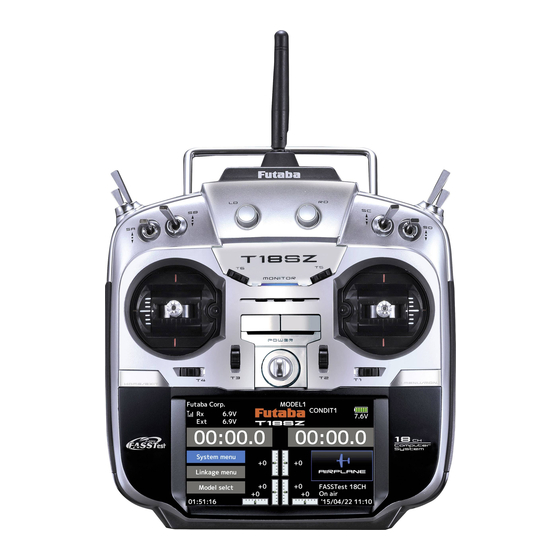
Сегодня обзор посвящен почти топовой системе радиоуправления от футабы — 18-ти канальной с индексом SZ. В конце статьи приведена видеоверсия обзора.
Корпус 18sz как у 14sg. С первого взгляда отличаются только экранами. За год эксплуатации потертостей не наблюдается, подписи тумблеров пока не стерлись.
Кнопка включения, наконец-то она стала не механической.
включается коротким нажатием любой кнопки
выключается коротким нажатием двух кнопок или удержанием 2-3 секунды одной.
Балансировка на ремне меня устраивает, немного передняя.
18sz поддерживает 5 стандартов FASST 7ch, FASST Multi, FASSTest 18/12ch, SFHSS, T-FHSS
Общее количество каналов 18, 16 пропорциональных и 2 дискретных включено/выключено, 6 цифровых триммеров, 8 переключателей из которых 6-трех позиционных и 2 — двух позиционных, один из них подпружиненный, 2 крутилки и 2 слайдера.
Поддержка 8 типов автоматов перекоса для моделей вертолета, 13типов крыла для самолетов и планеров
Стики на 4 подшипниках как на топовой футабе, очень приятные, мягкие, плавные. Отличие от 14sg ощущается при первых движениях. Стики удобные, можно управлять как одним пальцем, так и щипком. Можно отрегулировать наклон стиков, они могут быть в одной плоскости или в развалочку.
На данный момент есть 4 моды, поменять моду можно самостоятельно.
У меня вертолетная версия, она с плавным перемещением и коротким ходом стика газа. Ограничители при желании можно снять, после чего надо будет сделать калибровку стиков.
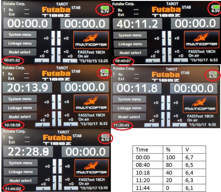
Аппаратура комплектуется литий-феррум-полимерным аккумулятором LIFe 6,6v емкостью 2100mA. Особенностью этого типа аккумулятора является постоянным напряжением 3.2 В с банки на выходе. В инструкции сказано, что его можно заряжать от штатного зарядного устройства. Я рекомендую использовать специальное зарядное устройство с поддержкой данного типа батарей и балансировочным устройством.
Батарейка на экране отображается в графическом виде из 5 сегментов, при полностью заряженном аккумуляторе отображаются сегменты зеленого цвета, при низком уровне заряда батареи крайний сегмент будет красного цвета
От полностью заряженного аккумулятора до отключения по отсечке аппаратура проработала 11 часов 44 минуты, официально заявлено около 7-8 часов. При этом яркость экрана выставлена на 10, минимальная подсветка так же на 10, аппаратура работала режиме Fastest восемнадцать каналов.
Экран цветной сенсорный 4,3 дюйма с разрешением 480 x 320 (HVGA). Экран матовый. Чтобы его не повредить наклеил защитную матовую пленку от обычного смартфона. На солнце экран плохо видно. Но когда выполняешь настройки на таком экране, получаешь одно удовольствие.
На солнце при максимальной яркости подсветки (20).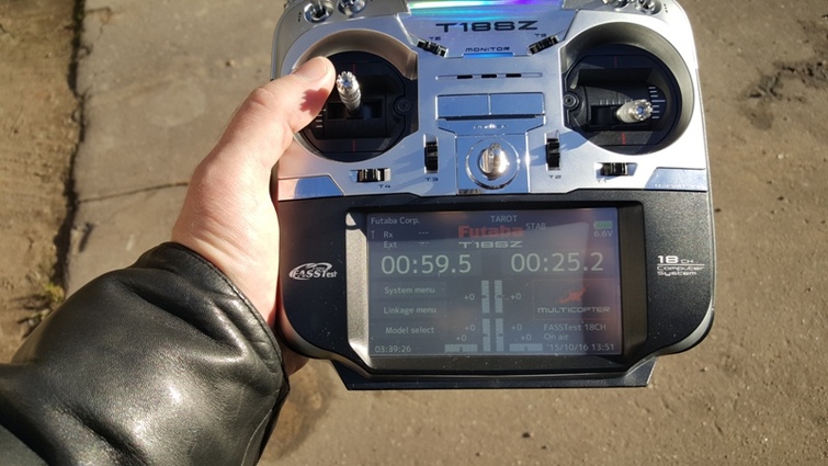
Яркость подсветки = 10.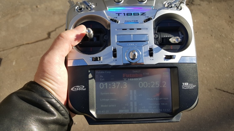
Через экран получаем доступ к System menu, Linkage menu, Model select и Model menu. Таймеры запускаются, останавливаются и сбрасываются прикосновением к экрану.
Левая кнопка над экраном Выход/Домой из меню, коротким нажатием вызывает экран телеметрии, а длинным — блокировку, Правая кнопка при коротком нажатии вызывает Пользовательское меню, длинным сервомонитор.
В нижней части экрана видно, что в пульте есть Дата и время. Которые используются только при создании новой модели.
В 18sz установлен динамик и она научилась разговаривать, пользовательские звуки не установить.
Название модели и имя пилота увеличено до 15 символов, теперь могу написать имя и фамилию полностью.
Можно настроить 8 полетных режимов для любого типа модели . Для каждого режима задается название и оно будет отображаться на экране.
Настраиваются логические переключатели для любого типа модели
Кривые на 17 точек. Можно запрограммировать самую сложную кривую газа или кривую отклонения рулевых поверхностей.
Для управления моделью предусмотрено множество настроек.
Многие скажут, что по функционалу Таранис с опенТХ-ом не имеет равных, но мне даже этот функционал избыточен.
Мне главное отточенное управление и надежность. Все работает без нареканий, отказов по причине радиоуправления не было.
На официальном сайте есть утилита для переноса настроек моделей из младшей и старшей модели в 18sz.
Что мне не нравится:
приемник не привязан к модели, надо быть внимательным с выбором модели.
неудобный экран телеметрии, для вывода питания приемника и силовой батарей, хотелось бы иметь возможность только двух значений. Да, они есть на основном экране, но там они отображаются очень мелко.
При записи логов нет никакой иконки.
В логах не используется дата и время не в названиях, ни в событиях.
При слабом сигнале от приемника нет никакой сигнализации
И надо не забывать, что аппаратура в выключенном состоянии полностью не обесточивается, это сделано для того чтобы она не забывала дату и время. Поэтому при длительном хранении физически отключаем батарею
Видеоверсия
Добавлю еще видео распаковки.
- Отправить эту тему
- Печать
Страницы: 1 … 3 4 [5] 6 7 … 15 Вниз

Тема: Новая FUTABA 18SZ (обновлено 2.5.2020) (Прочитано 55717 раз)

0 Пользователей и 1 Гость просматривают эту тему.
У меня бы за час семейный бюджет рухнул 
Отправлено с моего Lenovo S820 через Tapatalk
Я не червонец, чтобы нравиться всем!
У меня бы за час семейный бюджет рухнул
Отправлено с моего Lenovo S820 через Tapatalk
Как я вас понимаю;)
При рублевой структуре доходов/расходов это вполне объяснимо.
Жалеть об упущенном — опасно и портит нервную систему 
Лучше задуматься, что делать сегодня , когда курс 70
18SZ имеет свою операционную систему (не винда, как в MZ, а что-то своё ) и все функции зашиты в ней.
« Последнее редактирование: 21 Сентябрь, 2015, 07:32:11 am от alex_nikiforov »
Кто знает — настройки-модели переносятся из 14SG в 18SZ и наоборот ?
Patrik
А вот это косяк, неудобство однако!
Придётся перенастраивать всё, а у кого 5-7 моделий или больше! 
Косяк, но не смертельный.
Модель переносится за 7 минут.
P/S
Я вам больше скажу: из 18MZ тоже не переносится 
Футаба стимулирует развитие мелкой моторики у своих клиентов
Молодец!
Почувствуешь разницу
Потихоньку изучаю новый пульт.
Стики на самом деле отличаются, я не великий знаток, но разница с 14sg ощутимая.
Все основные настройки понятны и просты, а вот по телеметрии для себя отметил два момента.
Странно, что окно вывода телеметрии в 18sz нельзя настроить, как в 14-ой. Перечитал мануал, но ничего подобного не нашел. На вертолете я привык к напряжению силовой батареи и питанию приемника, другие датчики на электричке мне не нужны, зачем мне 4 ячейки для информации.
И второй момент, почему-то на экране телеметрии нет уровня сигнала, в 14-ой он есть. Для вертолета это не важно, а для коптера и самолета уровень сигнала очень даже пригодится.
- Отправить эту тему
- Печать
Страницы: 1 … 3 4 [5] 6 7 … 15 Вверх
Все протоколы Futaba — в одном модуле TM18!
Правильный выбор приёмника очень важен – нет смысла использовать самый дорогой приёмник на зальной модели или тренере, для многих самолётов и вертолётов критичен вес, для FPV полётов и тренировок планеристов-спортсменов необходима телеметрия. Более того, многие модели при покупке уже имеют установленный приёмник, в этом случае имеет значения совместимость протоколов. Продуманный выбор отличает опытного моделиста от начинающего. 18SZ даёт возможность использовать все приёмники Futaba 2.4 GHz!
Запатентованные технологии Futaba
- Futaba FASST – скачкообразный протокол передачи данных, обеспечивает максимальную помехозащищенность, безопасность, скорость отработки и разрешение ручек управления;
- Futaba S-FHSS, Futaba T-FHSS – упрощенные протоколы передачи данных, внедрение которых позволило экономным моделистам познакомиться с высококачественной японской аппаратурой. Многие производители, например – Nine Eagles и XK Innovations, предлагают модели с логотипом FTR (Futaba Transmitter Ready) – он обозначает возможность привязки встроенного приемника к Вашей аппаратуре Futaba S-FHSS без дополнительных настроек!
- Futaba FASSTest – система телеметрии, обеспечивает передачу параметров в реальном времени по защищенному каналу;
- Futaba S.Bus и Futaba S.Bus 2 – технология последовательного подключения сервоприводов и других исполнительных устройств. Меньшее количество проводки на борту, принципиальная невозможность неправильного подключения сервомашинок, полная свобода в выборе места расположения бортового аккумулятора – лишь некоторые преимущества технологии.
Обновляемое программное обеспечение
Пройдите по ссылке, чтобы скачать и установить самые новые прошивки для 18SZ и других систем радиоуправления Futaba!
.gif)
Сенсорный дисплей, интуитивно понятное меню
Без сомнений, удобное меню понравится как профессиональным спортсменам и шоу-пилотам, так и любителям полетать в свободную минуту!
.jpg) |
Меню выбора типа модели с индивидуальными настройками:
|
.jpg) |
Меню настройки и привязки приёмника:
|
.jpg) |
Сервомонитор с возможностью тестирования Функция предназначена для того, чтобы проверить все настройки до первого вклячения модели, убедиться в правильном направлении работы рулей, корректной рабте микшеров и кривых. |
.jpg) |
Никогда настройка сложных моделей не была настолько простой! Графическое отображение каждого действия – залог одинаково понятной настройки как тренера или соосного вертолёта, так и пилотажной модели или копии чемпионского уровня! Вы всегда можете внести быстрые корректировки непосредственно на лётном поле! |
Особенности конструкции и комплектации
Механизм ручек управления (стиков) и потенциометры – такие же, как на флагманской аппаратуре 18 MZ! Это означает, что точность и разрешение управляющего сигнала, а также надёжность механики соответствуют самому высокому на сегодняшний день уровню, что подтверждено высшими результатами пилотов команды Futaba на самых престижных междумародных соревнованиях!

Удобные кнопки быстрой навигации дополняют сенсорный дисплей и великолепно выполненное меню. Эргономика — один из главных приоритетов инженеров компании Futaba! Решения, выбранные при создании легендарной системы Futaba 14MZ на сегодня отточены и доведены до совершенства! T18SZ — передатчик, который всегда хочется взять в руки!

В комплекте – 8-канальный (с возможностью расширения до 18-и каналов) FASSTest приёмник R7008SB. Он имеет встроенный порт для подключения датчиков телеметрии. Диапазон напряжения – 3.5-8.4 В, что позволяет применять бортовые Li-Po аккумуляторы и современные высоковольтныйе сервомашинки! Используется система последовательного подключения сервоприводов и исполнительных устройств S.Bus.
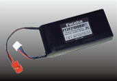
В комплекте – 2S Li-Fe аккумулятор большой ёмкости – 2100 мАч со стандартным разъёмом Futaba. Проблема быстрого разряда высокопроизводительных передатчиков с цветными дисплеями полностью решена! Большой плюс выбранного типа аккумуляторов для российского климата – широкий диапазон рабочих температур (от -30 до +50°С). Возможен быстрый заряд при помощи внешнего зарядного устройства.
Максимум информации – в списке особенностей Futaba 18SZ!
В комплекте:
- Передатчик T18SZ
- Приёмник R7008SB
- Аккумулятор для передатчика Li-Fe 6.6V 2100 mAh
- Инструкция