-
Contents
-
Table of Contents
-
Bookmarks
Quick Links
14 CHANNEL COMPUTER SYSTEM
TM
TM
1M23N27907
Related Manuals for FUTABA 14SG
Summary of Contents for FUTABA 14SG
-
Page 1
14 CHANNEL COMPUTER SYSTEM 1M23N27907… -
Page 2
14 CHANNEL COMPUTER SYSTEM Technical updates and additional programming examples available at: http://www.futaba-rc.com/faq Entire Contents © 2012… -
Page 3
INTRODUCTION……….4 ..34 ……….34 ……… 4 ……….34 … 5 ..34 ……..6 ……34 ….. 34 …………. 6 ………… 35 …………36 ……….. 10 ….37 ……….10 …… 39 … 11 …………12 . 40 …….. -
Page 4
…………. 73 ……… 117 …………76 ……..118 …………78 ……..119 ……….79 ….120 …………80 ……121 …………81 ………… 82 ..123 ……83 ……….. 124 ……..84 ……….. 125 ……..85 ……. 127 ……86 …. -
Page 5
14SG series digital proportional R/C system. This system is extremely versatile and may be used by beginners and pros alike. In order for you to make the *FASSTest: Futaba Advanced Spread Spectrum Technology extend system telemetry change without notice. hobby’s “off season” to ensure safe operation. -
Page 6
The responsible party of this device compliance is: Futaba Service Center Futaba Corporation of America is voluntarily participating in an industry-wide program to collect You may contact your local recycling center for information on where to return the spent battery. Please America’s involvement in this program is part of its commitment to protecting our environment and conserving natural resources. -
Page 7
Warning: Always keep electrical components away from small children. FLYING SAFETY WARNING Have regular maintenance performed. Although your 14SG protects the model memories with transmitter still should have regular checkups for wear and tear. We recommend sending your system service. -
Page 8
NiMH/NiCd Battery Charge the batteries! during the session pay attention to the duration of usage. Where to Fly We recommend that you fly at a recognized model airplane flying field. You can find model clubs Aeronautics. newcomer training are available. Contact the AMA at the address or toll-free phone number below. Academy of Model Aeronautics or via the Internet at http:\www.modelaircraft.org as well as the presence and location… -
Page 9
NiMH/NiCd Battery Safety and Handling instructions IMPORTANT! Use only the Futaba special charger included with this set or other chargers approved by Futaba to charge the NiMH batteries in the T14SG transmitter included with this set. It is important to understand the operating characteristics of NiMH/NiCd batteries.Always read the… -
Page 10
2. Turn on the transmitter power and allow your transmitter to reach its home screen. 4. Turn on your receiver power. the problem. 7. Complete a full range check. your motor/engine. 9. Turn off receiver power. 10. Turn off transmitter power. In order to maintain complete control of your aircraft it is important that it remains visible at all times Water or moisture may enter the transmitter through the antenna or stick… -
Page 11: Before Use
BEFORE USE Features FASSTest system The T14SG transmitter has adopted the newly developed bidirectional communication system «FASSTest» . Data from the receiver can be checked in your transmitter. FASSTest is a maximum 14 channels (linear 12 channels + switch 2 channels) 2.4GHz dedicated system. S.BUS2 system By using the S.BUS2 system multiple servos, gyros and telemetry sensors are easily installed with a minimum amount of cables.
-
Page 12
Your 14SG includes the following components: *The set contents depend on the type of set. Transmitter T14SG (2-stick, 14-channel, FASSTest-2.4G system) Transmitting frequency: 2.4GHz band Receiver R7008SB (FASSTest-2.4G system, dual antenna diversity, S.BUS system) Weight: 0.38 oz. (10.9g) (*1) When using ESC’s make sure that the regulated output capacity meets your usage application. -
Page 13
Note that the T14SG transmitter may be connected to another T14SG system, as well as to any other models of Futaba transmitters. The T14SG transmitter uses one of the three cord plug types according to the transmitter connected. -
Page 14: Transmitter Controls
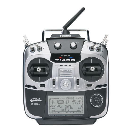
Transmitter controls ●Antenna ●Monitor LED ●Volume(LD,RD) ●Switch(SC,SD,SG,SH) ●Switch(SA,SB,SE,SF) ●Slide Lever(LS) ●Slide Lever(RS) ●Stick ●Stick (J3) (J2) (J4) (J1) ●HOME/EXIT ●U.MENU/MON. Button (User Menu/ Servo Monitor) Button ●Digital Trim (T1,T2) ●Digital Trim (T3,T4) ●SensorTouch (SYS,LNK, MDL,RTN,S1) ●Neck Strap Attachment ●LCD ●Power Switch ●Battery Cover *It slides upwards and turns on.
-
Page 15
Transmitter’s Antenna: Caution As with all radio frequency transmissions, the strongest area of signal transmission is from the sides of the transmitter’s antenna. As such, Please do not grasp the transmitter’s the antenna should not be pointed directly at the Doing so may degrade the quality of the RF easily move the antenna to correct this situation. -
Page 16
Switch (SA-SH) Slide Lever the setting screen of the mixing functions. Digital Trim LS (Left), RS (right): The slide lever LS and RS offer analog input. *The T14SG transmitter beeps when the lever comes to the center. direction on the setting screen of mixing functions. Digital Trim T1, T2, T3 and T4: This transmitter is equipped with four (4) HOME/EXIT and U.MENU/MON. -
Page 17
Touch sensor operation Data input operation is performed using the touch sensor. SensorTouch™ operation Condition Working If the screen has more than one page. (Ex. P-MIX screen) The cursor moves to the top of next page. If the screen have only one (1) page. The cursor moves to the top of page. -
Page 18
Note: the RTN button. The sensors may mis-read your touch as a reverse rotation if the circle is smaller, or performed on the inside edge of the RTN button. Adjustment of stick lever tension The tension of the self-return type stick lever can be adjusted. -
Page 19
*Turning the screw clockwise increases the tension. (Mode 2) (Mode 1/2) (Mode 1/2) (Mode 1) + screw is clockwise. + screw is counter-clockwise. Stick tension maximum Stick tension minimum A screw is kept A screw is kept from coming out from coming out from a line. -
Page 20
*Initializing destroys all the data previously saved on the card. *An SD card formatted to the T14SG cannot be written must be converted and written by the Futaba File System This special conversion software can be downloaded from Futaba’s web site at: http://www.futaba-rc.com/software-updates.html… -
Page 21
To use an SD card with the T14SG, the card Saving model data and update files (released from Futaba) to the SD card from your own does not have to be reformatted. Formatting is PC, you can transfer those file to your T14SG performed by the T14SG. -
Page 22
Connector/Plug Trainer Connector S.BUS (S.I/F) Connector Charge Plug Earphone Plug Connector for battery charger Connector for trainer function This is the connector for charging the NiMH When you use the trainer function, connect the optional trainer cable between the transmitters transmitter. -
Page 23
Do not use the transmitter as it is. Send it to the Futaba Service Center. ③ Battery cover will open downward. ery cover will open… -
Page 24
Don’t charge the LiFe battery with the 6 . T 1 4 S G i s t u r n e d o n a n d [ L I N K A G E NiMH charger of 14SG attachment. MENU]=>[WARNING]=>[LOW BATTERY] is * Be sure to remove from T14SG and to charge with the called. -
Page 25
Receiver nomenclature Danger Before using the receiver, be sure to read the Don’t connect a connector, as shown in a precautions listed in the following pages. Receiver R7008SB *It will short-circuit, if it connected in this way. A short circuit across the battery terminals may cause abnormal Warning S.BUS2 connectors Don’t connect an S.BUS servo / gyro to… -
Page 26
Danger Don’t touch wiring. * There is a danger of receiving an electric shock. Do not short-circuit the battery terminals. * A short circuit across the battery terminals may cause Please double check your polarity ( + and − ) when hooking up your connectors. * If +… -
Page 27
Receiver’s Antenna Installation has adopted a diversity antenna system. This allows the receiver to obtain RF signals on both antennas and *Must be kept as straight as possible. Antenna Coaxial cable R7008SB Receiver To obtain the best results of the diversity f u n c t i o n , p l e a s e r e f e r t o t h e f o l l o w i n g instructions: Antenna… -
Page 28
Safety precautions when you install Mounting the Servo receiver and servos Warning Wood screw 2.3-2.6mm nut washer Rubber Rubber Connecting connectors grommet grommet Brass eyelet Brass eyelet Servo mount Be sure to insert the connector until it Servo mount stops at the deepest point. 2.3-2.6mm screw How to protect the receiver from vibration (Airplane/Glider) -
Page 29
S.BUS/S.BUS2 Installation with models that use a large number of servos. In addition, the wings can be quickly installed to the fuselage without any erroneous wiring by the use of only one simple wire, even when there are a large number of servos used. -
Page 30
S.BUS Wiring example Receiver *When using 8/SB as S.BUS, you must set the receiver to Mode B or Mode D. See R7008SB CH MODE TABLE. ●S.BUS Servo Since the channel number is memorized by the S.BUS itself, any connector can be used. When the SBD-1 (sold separately) is used, ordinary servos can be used with the S.BUS system. -
Page 31
S.BUS2 System When using the S.BUS2 port, an impressive array of telemetry sensors may be utilized. S.BUS2 TABLE S.BUS2 S.BUS Servo Servo Receiver port Telemetry sensor S.BUS Gyro S.BUS2 Gyro S.BUS ○ ○ × S.BUS2 × (※) ○ ○ (※)Don’t connect S.BUS Servo, S.BUS Gyro to S.BUS2 connector. -
Page 32
S.BUS/S.BUS2 device setting S.BUS/S.BUS2 servos or a telemetry sensor can be connected directly to the T14SG. Channel setting and other data can be entered for the S.BUS/S.BUS2 servos or sensors. → → <Before Use>… -
Page 33
Telemetry System the S.BUS2 port. Using the S.BUS2 port an impressive array of telemetry sensors may be utilized. It also includes both standard PWM output ports and S.BUS output ports. * Telemetry is available only in the FASSTest 14CH mode. (12CH mode displays only Receiver battery voltage and Extra battery voltage.) ●Telemetry sensor (sold separately) Your aircrafts data can be checked in the… -
Page 34: Basic Operation
BASIC OPERATION Battery Charging Before charging batteries, read the «Cautions for handling battery and battery charger» in the section «NiMH/NiCd Battery Safety and Handling Instructions». *Battery charging will not automatically stop. Remove the How to charge the NiMH battery HT5F1800B battery and transmitter from the charger and remove the for the transmitter charger from the wall socket.
-
Page 35
How to turn transmitter power ON/OFF When turning on the power, the T14SG transmitter will begin emmiting RF automatically *below 1/3 stick, the warning display goes off. The T14SG transmitter also offers the ability to auto shut-down. When turning on the power of the transmitter THR Stick Slow Registration of the user’s name If so desired, the T14SG transmitter can… -
Page 36
Home screen button. The setting screen appears. System timer Key lock the latest reset. (Hour):(Minute) HOME/EXIT button for one second to lock/unlock the key operation. touch the RTN button for one second In the key lock mode the key icon is to reset the system timer. -
Page 37
User Menu Warning A user menu which allows the user to customize and display frequently used functions has been added. 1. When the «U.MENU» button is pushed for Check the battery voltage as often as two seconds, the user menu appears. possible and try to charge the battery earlier. -
Page 38
Link procedure (T14SG/R7008SB) the ID code is stored in the receiver and no further linking is necessary unless the receiver is to be used with another transmitter. When you purchase additional R7008SB receivers, this procedure is necessary; otherwise the receiver will not work. 6. -
Page 39
11. When a telemetry function is enabled, the receiving interval (down-link interval) of sensor data can be changed. If a DL interval is increased, the response of the sensor data display becomes slower, but stick response will improve. Initial value: 1.0s Adjustment range: 0.1s~2.0s * If there are many FASSTest systems turned on around your receiver, it might not link to your transmitter. -
Page 40
Range Testing Your R/C System The T14SG transmitter incorporates a system that reduces its power output and allows you to perform such a range check. Range check mode Range check procedure 1. With the «Range check mode» on, walk We have installed a special «Range check away from the model while simultaneously mode»… -
Page 41: Receiver And Servo Installation
RECEIVER AND SERVO INSTALLATION Receiver and servos connection Connect the receiver and servos in accordance with the connection diagram shown below. Always read the section [Before using]. When mounting the receiver and servos to the fuselage, connect the necessary points in accordance with the model’s instruction manual.
-
Page 42
Servo connection by model type The T14SG transmitter channels are automatically assigned for optimal combination according to the type selected with the Model Type function of the Linkage Menu. The channel assignment (initial setting) for each model type is shown below. Connect the receiver and servos to match the type used. *The set channels can be checked at the Function screen of the Linkage Menu. -
Page 43
Airplane/glider Flying wing, Delta wing R 2Aileron 2Aileron+1FLAP 2Aileron+2FLAP 2Aileron+4FLAP 4Aileron+2FLAP X Airplane Glider Airplane Glider Airplane Glider Airplane Glider Airplane Glider Aileron Aileron Aileron Aileron Aileron Aileron Aileron Aileron Aileron Aileron AUX4 AUX4 AUX4 Aileron2 Aileron2 Aileron2 Aileron2 Throttle Motor Throttle Motor… -
Page 44
Helicopter ● FASSTest14CH/FASST MULTI/FASST 7CH/S-FHSS All Other H-4, H4X Swash Aileron Aileron Elevator Elevator Throttle Throttle Rudder Rudder Gyro/RUD Gyro/RUD Pitch Pitch Governor Governor Needle Elevator2 Gyro2/AIL Gyro2/AIL Gyro3/ELE Gyro3/ELE AUX1 AUX1 AUX1 AUX1 ● FASSTest12CH All Other H-4, H4X Swash Aileron Aileron Elevator… -
Page 45
MODEL BASIC SETTING PROCEDURE Airplane/glider basic setting procedure 1. Model addition and selection 3. Fuselage linkage Initially, the T14SG assigns the first model to Connect the ailerons, elevators, throttle, rudder, model-01 in the transmitter. The Model Select etc. in accordance with the model’s instruction function of the Linkage Menu is used to add manual. -
Page 46
throttle stick in the 1/3 or less (slow side) position. The offset amount of the aileron, elevator, and flap servos can be adjusted as needed. Also the be adjusted. You can also set the Auto Mode, which will link Airbrake to a stick, switch, or dial. A separate stick switch or dial can also be set as the ON/OFF switch. -
Page 47
Helicopter basic setting procedure This section outlines examples of use of the helicopter functions of the T14SG. Adjust the actual values, etc. to match the fuselage used. functions for the chosen model type. Six swash types are 1. Model addition and selection available for helicopters. -
Page 48
4. Servo Connection 5. Throttle/Pitch curve setting Connect the throttle rudder, aileron, elevator, This function adjusts the throttle or pitch pitch, and other servos in accordance with the operation curve in relation to the movement of the kit instruction manual. For a description of the throttle stick for each condition. -
Page 49
10. Throttle cut setting Throttle cut provides an easy way to stop the Note: When using a Futaba GY Gyro, or other at idle. The action is not functional at high throttle heading hold gyro, this Pitch to RUD mixing to avoid accidental dead sticks. -
Page 50
*If throttle mixing is necessary for a compensation for slowing of engine speed caused by swash plate operation during aileron or elevator operation, please refer to the THROTTLE MIX function. <Model Basic Setting Procedure>… -
Page 51: System Menu
SYSTEM MENU The System Menu sets up functions of the transmitter: This does not set up any model data. <SensorTouch™> HOME/ EXIT RETURN System Menu functions table [TRAINER]: Starts and sets the trainer system. [DISPLAY]: LCD and back-light adjustment [USER NAME]: User name registration [SOUND]: Turns off the buzzer.
-
Page 52
TRAINER NOTE: This trainer system can be used in the T14SG trainer system makes it possible for the following manner; instructor to chose which channels and operation 1. With the T14SG transmitter and a conventional modes that can be used in the students transmitter. transmitter, if the channel order is different, The function and rate of each channel can be it is necessary to match the channel order… -
Page 53
<SensorTouch™> R T N H O M E / E X I T RETURN Note: The trainer function won’t be turned Mode and switch selection on unless the Instructor’s transmitter receives signals from the student’s transmitter. Be sure to confirm this after connecting your trainer cable. -
Page 54
*When you want to reset the value to the initial state, touch the RTN button for one second. Changing the student’s channel *The setting above allows setting of the channel assignment of student side when [MIX] or [FUNC] was selected. <Functions of System Menu>… -
Page 55
DISPLAY LCD contrast, back-light brightness and back- light off-timer adjustment are possible: Moreover, a display unit can be chosen from the metric system or yard/pound. <SensorTouch™> R T N . H O M E / E X I T RETURN LCD contrast adjustment Back-light off-timer… -
Page 56: User Name
USER NAME This function allows the modelers to change the T14SG user name. *A name of up to 10 characters can be entered as the user name. Please note that a space is also counted as one character. <SensorTouch™> R T N …
-
Page 57
SOUND The warning sound and other sounds of the T14SG transmitter can be turned off. *When “WARNING” was set to OFF, the no operation alarm (30 minutes), mixing warning sound, and low battery alarm sounds also turned off. <SensorTouch™> R T N . -
Page 58
Note: This will not change the throttle ratchet, H/W reverse etc. Those are mechanical changes that This function reverses the operation direction of must be performed by a Futaba service center. the sticks, switches, trimmer levers, and knobs. Note: This setting reverses the actual operation… -
Page 59
Stick calibration method *J3 and J4 correction is described below. J1 and J2 corrections are performed using the same procedure. <Functions of System Menu>… -
Page 60
START SEL. START SEL is a function which starts and can turned ON. With a few quick touches, it is possible perform a model selection immediately. to change models whereas before it would require a multi-step process. The T14SG stores up to four Each time, it is convenient for the modeler models in the Quick Select offerings. -
Page 61
Model Select Screen Assigning models to the sensor buttons: There are four sensors/buttons that correspond This allows the Model Select screen to be accessed with the SensorTouch: Link (LNK), Model (MDL) immediately upon turning ON the transmitter. System (SYS) and S1. As such, it is possible to offer * Please note: this function cannot be utilized at the same time up to four models available through the Quick Select as the Quick Select function. -
Page 62
SensorTouch to move to the activation setting options. Model (MDL) is the default setting. Press the Return (RTN) button to bring forth the options, then scroll to the ALWAYS setting using the SensorTouch pad. Press the Return (RTN) button Using the Model Select Function: *Please note: Even if the Model Select function is active, the Power Mode screen will appear when the transmitter is turned ON while simultaneously pressing the Return (RTN) button. -
Page 63
AUTO LOCK The Auto Lock function makes it possible to lock START LOCK the transmitter to prevent any unwanted input from Auto Lock functions automatically when the model changes or power is turned on. The auto lock function can be set in two ways. *To temporarily allow access to the T14SG programming press and hold the S1 or HOME/EXIT bitton for one second. -
Page 64
INFO The T14SG system program version information, The language displayed in home, menu, and SD card information (current and maximum setup screen is selectable. ID are displayed on the Information screen. *When the SD card is not inserted, the SD card information is not displayed. -
Page 65
SBUS SERVO An S.BUS servo can memorize the channel and various settings you input. Servo setting can be performed on the T14SG screen by w i r i n g t h e s e r v o a s s h o w n i n t h e f i g u r e . <SensorTouch™>… -
Page 66
S.BUS Servo Description of function of each parameter *There are a function which can be used according to the kind of servo, and an impossible function. Displays the ID of the servo whose parameters are to be read. It cannot be changed. Channel of the S.BUS system assigned to the servo. -
Page 67
OFF : It is the boost ON at the time of low-speed operation.(In the case of usual) ON : It is always the boost ON.(When quick operation is hope) The characteristic when the servo is stopped can be set. When smaller than the standard value, the characteristic becomes an overshoot characteristic. If the value is larger than the standard value, the brake is applied before the stop position. -
Page 68
FUNCTIONS OF LINKAGE MENU The Linkage Menu is made up of functions The functions which can be selected depend on which perform model addition, model type the model type. A typical menu screen is shown selection, system type, end point setting, and other below. -
Page 69: Servo Monitor
SERVO MONITOR This is used for testing servo movement. In order to prevent any potential difficulties, “Moving Test” (repetition mode) and “Neutral the servo test function will be inoperable, or the Servo Test function is not operational if the The “Neutral Test” is good for finding the Throttle Cut is ON in either airplane or helicopter neutral position of a servo horn.
-
Page 70: Model Select
MODEL SELECT This function is used to load the settings of the The Copy function is used to copy parameters, desired model into the T14SG’s memory. settings, etc. from one model data into a second memory. It may be used for getting a head-start on The settings may be selected from either the setting up models with almost the same settings (only transmitter’s internal memory or an SD card.
-
Page 71
Model deletion *The model stored in the transmitter memory or an SD card can be deleted. *The current model can not be deleted. *A name of up to 10 characters long can be entered as the model name. (A space is also counted as one character.) Model copy *A copy can be made of the model stored in the transmitter memory or an SD card. -
Page 72: Model Type
MODEL TYPE losing this data, or back it up to another Six swash types are available for helicopters. memory using the copying functions. Six types of main wings and three types of tail When changing the helicopter swash type wings are available for airplanes and gliders. within the following groups, you can leave Functions and mixing functions necessary for each the settings other than the SWASH function.
-
Page 73
Model type selection (Airplane, Glider) Model type selection (Helicopter) <Functions of Linkage Menu>… -
Page 74
SYSTEM System Type selection FASSTest 12CH mode. The T14SG is for 2.4GHz only. The system Dual receiver function (only FASSTest 14CH can be changed from among 5 choices: FASSTest mode) 1 4 C H , FA S S Te s t 1 2 C H , FA S S T M U LT I , Dual receivers can be linked with the T14SG. -
Page 75
Telemetry function (FASSTest mode only) To use the telemetry function, set “Telemetry” Area mode selection (Frequency range) to “ACT”. procedure DL Interval (FASSTest mode only) When a telemetry function is enabled, the receiving interval (down-link interval) of sensor data can be changed. If a DL interval is increased, the response of the sensor data display becomes slower, but stick response will improve. -
Page 76
The example for choosing System Type -Want to use an -Want to use a S-FHSS system miniature receiver -Response speed has -Want to use a miniature receiver for indoor planes priority over number previously used of channels receiver as is -Telemetry requires only the current receiver battery… -
Page 77
FUNCTION When you select model and wing (swash) types, For FASST 7CH mode, you can set only 7 linear you will find that the optimized combinations of channels. For S-FHSS mode, you can set only 8 servo output channels and functions have been linear channels. -
Page 78
each condition. *[NORMAL]/[REVERSE] selection is possible in «ATL» mode. Throttle trim (helicopter only) * The throttle trim in conditions other than «Normal» Trim setting condition can be inhibited. *The trim setup screen is displayed. *When «X» is displayed, THR trim is inhibited in conditions other than normal condition. -
Page 79
SUB-TRIM The Sub-Trim function is used to set the servo neutral position, and may be used to make fine adjustments to the control surface after linkages and pushrods are hooked up. When you begin to set up a model, be sure that the digital trims are set to their center position. -
Page 80
REVERSE Servo Reverse changes the direction of an to tell whether the servo needs to be reversed or a individual servo’s response to a control input. setting in the function needs to be reversed. See the instructions for each specialized function for further For CCPM helicopters, be sure to read the details. -
Page 81: Fail Safe
FAIL SAFE The Failsafe function may be used to set up predefined control suddenly moves to a position positions that the servos move to in the case of you did not command, land at once and check your radio interference. receiver battery.
-
Page 82: End Point
END POINT The End Point function adjusts the left and right servo throws, generates differential throws, and will correct improper linkage settings. The travel rate can be varied from 0% to 140% in each direction on channels 1 to 12(FASSTest 12CH mode).
-
Page 83: Servo Speed
SERVO SPEED * It will overlap, if speed control of a S.BUS servo setup is The speed of the servo from 1CH to 12CH of used at the time of S.BUS servo use, and speed changes. operation can be set up. Please use one either.
-
Page 84
THR CUT *Since conditions are not offered when an Airplane is selected, Throttle cut provides an easy way to stop the the Throttle Cut options will vary from the options noted engine. Generally speaking, modelers will do so below. *The Throttle Cut POS and SW settings are utilized for all The action is not functional at high throttle to conditions. -
Page 85
The Idle Down function lowers the engine to its idle position. Like Throttle Cut, this is usually stick at idle. The action is not functional at high throttle to avoid accidental dead sticks. The switch’s location and direction must be chosen, as it defaults to NULL. -
Page 86
This function limits the swash travel to a fixed range in order to prevent damaging the swash linkage by simultaneous operation of the ailerons and elevators. It is very useful in 3D aerobatics which use a large travel. <SensorTouch™> R T N … -
Page 87
Neutral Point The following compensation mixing is possible; PIT to AIL, PIT to ELE, AIL to PIT, ELE to AIL, At your linkages, if the servo horn deviates from and ELE to PIT (HR3 mode.) It adjusts the swash- a perpendicular position at neutral, the linkage plate to for proper operation of each control using compensation functions in this menu may not the corresponding compensation mixing. -
Page 88
Mixing rate setting procedure The HR3 swash-plate type will be used as an example to describe mixing rate setting. The mixing used in other swash modes may be different, however, the setting procedure is the same. *When making the following setting, Move the cursor to the item you want to set and touch the RTN button to switch to the data input mode. -
Page 89
Subtrim setting procedure Subtrim can be set on the last page of the swash setting screen. *The sub-trim value set here is reflected at sub-trim of the linkage menu. Pitch adjustment procedure The pitch adjustment function can be used on the last page of the swash setting screen. -
Page 90
T1-T4 SET. This function adjusts the digital trim’s step Only the trim displayed on the home screen can be moved to the center position without changing the actual trim’s memory position. When the flight conditions are set, the trim operation can be coupled with the conditions when combination mode is selected. -
Page 91
The T14SG includes an audible alarm that sounds when the transmitter’s battery voltage drops below a pre-determined setting; adjustable for cell types and voltages. Mixing warning at power ON can be reset to OFF. <SensorTouch™> R T N H O M E / E X I T RETURN Accessing and Activating the Low Battery Alarm… -
Page 92
TELEMETRY This screen displays your choice of data from the *It cannot be used in FASST mode and S-FHSS mode. *Only receiver voltage and EXT voltage can be used in receiver. FASSTest12CH mode. Also warnings can be activated regarding *The FASSTest14CH mode can use all the telemetry functions. other data from your aircraft. -
Page 93
TELEMETRY : Rx-BATT. In this screen, the battery voltage of a receiver is *It cannot be used in FASST mode and S-FHSS mode. *Only receiver voltage and EXT voltage can be used in displayed. FASSTest12CH mode. If it becomes higher or lower than the setting an *The FASSTest14CH mode can use all the telemetry functions. -
Page 94
TELEMETRY : EXT-VOLT *CA-RVIN-700 or SBS-01V must be installed in the aircraft. The EXT-VOLT screen will display the data You will be alerted by an alarm or vibration if from the EXT-battery output from the R7008SB the voltage set by you is exceeded. receiver. -
Page 95
TELEMETRY : TEMP. *A temperature sensor must be installed in the aircraft. *It cannot be used in FASST mode and S-FHSS mode. TEMP. is a screen which displays/sets up the temperature information from an optional *Only receiver voltage and EXT voltage can be used in FASSTest12CH mode. -
Page 96
TELEMETRY : RPM *A RPM sensor must be installed in the aircraft. *It cannot be used in FASST mode and S-FHSS mode. RPM is a screen which displays / sets up the *Only receiver voltage and EXT voltage can be used in RPM information from an optional RPM sensor. -
Page 97
TELEMETRY : ALTITUDE *An altitude sensor or GPS sensor must be installed in the aircraft. ALTITUDE is a screen which displays / sets up the airfield is displayed. This sensor calculates the altitude altitude information from an optional altitude sensor or from atmospheric pressure. -
Page 98
TELEMETRY : VARIO *An altitude sensor or GPS sensor must be installed in the aircraft. VARIO is a screen which displays / sets up the status, the T14SG incorporates a different melody variometer information from an optional altitude for ascent and descent. Additionally, depending sensor or GPS sensor. -
Page 99
TELEMETRY : BATTERY *SBS-01V must be installed in the aircraft. In this screen, the battery voltage is displayed. *It cannot be used in FASST mode and S-FHSS mode. In order to use this function, it is necessary to *Only receiver voltage and EXT voltage can be used in connect External voltage connector of R7008SB ⇔… -
Page 100
TELEMETRY : DISTANCE *A GPS sensor must be installed in the aircraft. *The GPS sensor sold separately is necessary. Mount and Distance is a screen that displays and sets the connect the sensor in accordance with the sensor instruction altitude data from an SBS-01G (GPS Sensor) sold manual. -
Page 101
Alert setting when the aircraft approaches *When the RTN button is touched for one second, the rate is reset to the initial value. <SensorTouch™> R T N H O M E / E X I T RETURN Altitude … -
Page 102
TELEMETRY : SPEED *A GPS sensor must be installed in the aircraft. The speed screen displays and sets the speed data is displayed instead of air speed. Consequently, from an SBS-01G (GPS sensor) sold separately. with a head wind, the displayed speed decreases and with a tail wind, the displayed speed increases. -
Page 103
SENSOR This screen registers the telemetry sensors used Servos are classified by CH, but sensors are with the transmitter. When only one of a certain classified in units called “slot”. There are slots type of sensor is used, this setting is unnecessary from No. -
Page 104
This page is set when using multiple telemetry sensors of the same type. SENSOR : RELOAD When using multiple sensors of the same type the sensors must be registered in the transmitter. Connect all the sensors to be used to the T14SG as 3-way hub or Y-harnesses the following procedure. -
Page 105
SENSOR : RELOCATE This page is set when using multiple telemetry sensors of the same type. This function secures contiguous unused slots by rearranging the registration state when sensor registration and deregistration are performed 3-way hub repeatedly and the unused slots are fragmented. or Y-harnesses All the sensors to be used are connected. -
Page 106: Data Reset
DATA RESET All model setting: This function is designed to allow you to reset trim settings or all of the settings saved in the active Resets all Linkage and Model Menu functions model memory. You may individually choose to except for Frequency, Model Select, Low battery reset the following data;…
-
Page 107
MODEL MENU (COMMON FUNCTIONS) This section describes the D/R, program mixing, and other functions common to all model types. conditions can be used) Note: The T14SG is designed so that the airplane Before setting the model data, use the Model and glider (including EP glider) model types Type function of the Linkage menu to select the are compatible with aircraft of similar type… -
Page 108
CONDITION This function, in the Model menu, can be used Please note this is not applicable to airplane type selections. Note: To prevent accidental activation of any switch setting of those unused conditions to null [—]. <SensorTouch™> R T N … -
Page 109
<Model Menu (Common Functions)>… -
Page 110
Dual rate function is used to adjust the amount rate through the dual rate function. of throw and the operational curve of the stick Neutral position of the dual rate curve can be set. operational curve of the throttle function. Glider) This is normally used after the End Point programming has been completed to define the… -
Page 111
condition you want to adjust. *When the RTN button is touched for one second, the neutral position is reset to the initial value.) Setting Method] at the back of this manual. condition you want to adjust. *When the RTN button is touched for one second, the servo operation position is reset to the initial value.) condition you want to adjust. -
Page 112
Programmable mixing may be used to correct undesired tendencies of the aircraft, and it may also be have mixing remaining on all the time. that the motion of a command channel, called the The Programmable mixing includes a powerful link «master,»… -
Page 113
*The display blinks. Setting Method] at the back of this manual. *Effective when a function is set in the master channel. *The display blinks. *When the RTN button is touched for one second, the servo operation position is reset to the initial value. *The display blinks. -
Page 114
Note: Initial settings does not assign fuel mix to any channel. Prior to utilizing the Fuel Mix adjustments of engines that offer mixture control settings, select an unused channel on your carburetors. receiver and assign it accordingly for the mixture control. Additionally, please make sure that your [Control] and [Trim] are set to null [—]. -
Page 115
reset to the initial value.) *Needle high trim works as high trim based on the center. *This function is used to adjust the needle/engine rise characteristics during acceleration. This enables an acceleration function which temporarily increases the needle operation from the throttle stick. *The display blinks. -
Page 116
MODEL MENU (AIRPLANE/GLIDER FUNCTIONS) The dedicated mixes, etc. that are applicable position, use the Condition Select function to add when an airplane or glider model type is selected flight conditions. (Up to five conditions can be are displayed in this Model menu functions used) section. -
Page 117
AIL to RUD This function is used when airbrakes are necessary when landing or when diving, etc. during This mix is used when you want to coordinate the rudder with aileron operation for banking at shallow angles. [Airplane/glider, general] GYRO RUD to AIL This is a dedicated mix when a GYA Series gyro is used. -
Page 118
PIT CURVE This function adjusts the pitch curve for VPP (Variable Pitch Propeller) airplane. *Up to 3 conditions can be set. N O T E : W h e n V P P i s n o t a s s i g n e d t o a n y channel, the pitch curve is not displayed in and access the setup screen shown the model menu. -
Page 119
THR CURVE This function adjusts the throttle curve for optimum engine speed from throttle stick input. *When throttle curve is set to ON when there is no throttle function; this curve acts as the motor function. NOTE: If this throttle curve function is activated, and access the setup screen shown you can not use the THR-EXP function within below by touching the RTN button. -
Page 120
THR DELAY THR-DELAY function is used to slow the response of the throttle stick to simulate the slow response of a turbine engine, etc. *This function is the same as THR of servo speed. If it sets up in great numbers, it overlaps and a THR servo becomes late further. -
Page 121
AIL DIFF. The left and right aileron differential can be adjusted independently. can be adjusted. AIL1 AIL 2 (Main Aileron) (Main Aileron) AIL 3 AIL 4 and access the setup screen shown (Chip Aileron) (Chip Aileron) below by touching the RTN button. *The display screen is an example. -
Page 122
FLAP SET. FLP1/2, brake flaps: FLP3/4) can be adjusted independently for each servo according to the wing type. offset FLP 4 FLP 3 The camber flaps of a 4-flap model can (Brake Flap) (Brake Flap) FLP 1 be mixed with the brake flaps. (BRKFLP to FLP 2 (Camber Flap) (Camber Flap) -
Page 123
AIL to CMBFLP more This mix operates the camber flaps (FLP1/2) in the aileron mode. When the aileron stick is manipulated, the ailerons and camber flaps perform aileron operation simultaneously to FLP 1 FLP 2 (Camber Flap) (Camber Flap) AIL1 AIL 2 (Main Aileron) (Main Aileron) -
Page 124
AIL to BRAKEFLP This mix operates the brake flaps (FLP3/4) in the aileron mode. When the aileron stick is the aileron operation simultaneously and the roll FLP 4 axis is improved. FLP 3 (Brake Flap) (Brake Flap) AIL1 AIL 2 (Main Aileron) (Main Aileron) AIL 3… -
Page 125
AIL to RUD Use this mix when you want to mix the rudders with aileron operation. This allows the aircraft to bank at a steep angle. AIL1 AIL 2 (Main Aileron) (Main Aileron) AIL 3 AIL 3 (Chip Aileron) (Chip Aileron) RUDDER 2 RUDDER 1 Winglet… -
Page 126
RUD to AIL This function is used when you want to mix the ailerons with rudder input. It is used when rudder is applied during roll maneuvers such as, knife edge flight. It can be used to turn or AIL1 AIL 2 bank scale models, large models, etc. -
Page 127
1. Move the cursor to the curve rate setting the RTN button to switch to the data input mode. *When the RTN button is touched for one second, the rate is reset to the initial value.) and return to the cursor mode. 2. -
Page 128: Camber Mix
CAMBER MIX *Initial setting assigns camber operation to side lever LS. This function adjusts the rate of camber operation for the wing camber (ailerons, camber flaps, brake flaps) in the negative and positive can be made by changing the mixing rate directions.
-
Page 129
When setting a cut switch, move the cursor Setting method button to access the selection screen. Select the RTN button to switch to the data input *For a description of the switch selection method, see the touch sensor. description at the back of this manual. *The display blinks. -
Page 130
ELE to CAMBER This function is used when you want to mix the the flaps are lowered by up elevator, and lift is increased. and access the setup screen shown below by touching the RTN button. (Glider: Currently selected condition name) <SensorTouch™>… -
Page 131
CMBFLP to ELE When the camber/speed flaps are utilized, the aircraft might experience, a change in pitch. This mix compensates for such changes by incorporating elevator input. FLP 1 FLP 2 (Camber Flap) (Camber Flap) AILVATOR V-TAIL ELEVATOR ELEVATOR ELEVATOR 2 ELEVATOR 2 access the setup screen shown below by touching the RTN button. -
Page 132
BUTTERFLY This function is utilized to quickly slow the aircraft and reduce altitude by simultaneously raising the left and right ailerons and lowering the reference point can be offset. Butterfly (Crow) produces an extremely the following: 1. Slow the aircraft’s velocity. *For a description of the setting method, see the aileron differential function. -
Page 133
Setting method Offset point the RTN button to switch to the data input Settable Settable Settable touch sensor. * The range where mixing does not work close to the neutral *The display blinks. position of the elevator stick can be adjusted. (Glider only) Touch the RTN button to activate the When setting a switch, move the cursor to call the selection screen. -
Page 134
TRIM MIX This function adjusts the trim offset rates of the smooth transition between the two conditions. It is also possible to program a cut switch which will turn off the delay. As an example this function can be set up for Furthermore, you can set the auto switch, which will link the trim mix to a stick, switch, or dial. -
Page 135
Setting method *When the RTN button is touched for one second, the servo operation position is reset to the initial value.) the RTN button to switch to the data input and return to the cursor mode. touch sensor. When setting a cut switch, move the cursor *The display blinks. -
Page 136
AIRBRAKE This function is used to increase the aircraft’s drag and is useful for landing or diving, etc. The preset elevators and flaps (camber flap, Offset rate: brake flap) offset amount can be activated by a switch. Note: The input numerics are examples. Adjust the travel to match the aircraft. -
Page 137
Setting method Move the cursor to the aileron, flap or elevator speed item and touch the RTN button to switch to the data input mode. the RTN button to switch to the data input touch sensor. *The display blinks. *When the RTN button is touched for one second, the rate is Touch the RTN button to activate the reset to the initial value.) Touch the RTN button to return to the cursor… -
Page 138
GYRO Note: This setting does not assign a sensitivity This function is used when a GYA Series gyro channel. To do so, use the Linkage menu is used to stabilize the aircraft’s attitude. The prior to assigning the sensitivity channel sensitivity and operation mode (Normal mode/ (Gyro/Gyro2/Gyro3), be sure to select an AVCS mode) can be changed via a switch. -
Page 139
Touch the RTN button to change the gyro type and return to the cursor mode. *When a Futaba GYA gyro is used and [GY] type is selected, *When the RTN button is touched for one second, the the sensitivity set value is directly read in both the AVCS sensitivity is reset to the initial value.) -
Page 140
V-TAIL This function enables adjustments for left and right rudder angle changes during elevator and rudder operation of a V-tail airplane. V-tail is when two servos are used together to control rudder movement as elevators. In addition ELEVATOR to each elevator side moving up and down together, RUDDER (RUDDER 2) each side moves in opposite directions when moving… -
Page 141
AILEVATOR (Effective only when 2 servos used at the elevators) This function improves the performance of the roll axis by operating the elevators as ailerons. Ailevator is where each elevator in a standard (conventional) or v-tail moves independently, like ailerons on a wing. In addition to each elevator side moving up and down together, each side moves in opposite directions when moving as an Ailevator. -
Page 142
WINGLET This function adjusts the left and right rudder angles of airplanes with winglets. Winglets are used to improve the efficiency of aircraft by lowering the lift-induced drag caused by wingtip vortices. The winglet is a vertical or angled RUDDER 1 Winglet extension located at the tip of each wing. -
Page 143
MOTOR This function lets you set the speed when the motor of an F5B or other EP glider is started via a switch. The operation speed can be set for two ranges, slow speed flight and high speed flight the Linkage menu. (Speed 1/Speed 2). -
Page 144
current position Setting method main SW is still ON, the motor remains ON. When using motor speed function, move the [START SW function example] When the throttle (motor) stick is assigned as the «START SW», button to switch to the data input mode. and the low throttle position of the throttle curve is adjusted, the motor starts operating with the initial stick movement. -
Page 145
RUD to ELE This function is used when you want to mix elevator operation with rudder operation. It is used to correct undesirable tendencies when rudder is applied in rolling maneuvers such as, knife edge menu and access the setup screen shown below by touching the RTN button. -
Page 146: Snap Roll
SNAP ROLL This function selects the switch and rate (Example) Setting example for F3A adjustment of ailerons, elevators, and rudder when a snap roll is performed. *The snap roll up side left and right and down side left and right direction switches are selected here.
-
Page 147
Setting method touch the RTN button to switch to the data input mode. Select the master or single mode by scrolling the touch sensor. *The display blinks. Touch the RTN button to select the mode and return to the cursor mode. When setting a master switch, move the the RTN button to access the selection screen. -
Page 148
MODEL MENU (HELICOPTER) This section contains information on the Condition Select screen prior to adjusting the commands that apply to helicopters only. For instructions on Airplanes and Sailplanes, refer to used) the sections pertaining to those aircraft. The Dual Rate function and other functions Use the Model Type function in the Linkage Menu to select the swash type matched to the respective aircraft. -
Page 149: Pitch Curve
PIT CURVE/PIT TRIM Pitch Curve This function adjusts the pitch operation curve for each flight condition to optmize the model’s value at the corresponding points. performance in relationship to the throttle stick position. (Currently selected condition name) <SensorTouch™> R T N …
-
Page 150
Curve setting examples When actually creating a curve, input the rate entering the pitch rate at low, center, and high side (3 points or 5 points) at each condition. Curve ample Normal Curve Idle-up 1 Curve Idle-up 2 Curve Hold Curve Pitch Trim (Hovering pitch, high pitch, low pitch) Hovering pitch trim Setting method… -
Page 151
High Pitch/Low Pitch Trim Setting method high side and low side trim function. <Functions of Model Menu (Helicopter Functions)>… -
Page 152: Throttle Curve
THR CURVE/THROTTLE HOVER TRIM Throttle Curve Throttle curve function adjusts the throttle accompanying changes in the temperature, operation curve for each condition to optimize the engine speed to throttle stick movement. trimmed. Adjust the throttle so that rotor rotation is near the hovering point.
-
Page 153
Curve setting examples condition. When actually creating a curve, enter the the data of the 5 points 0% (low side), 25%, value). 50% (center), 75%, 100% (high) side for each ro le Curve ample Normal Curve Idle-up 1 Curve Idle-up 2 Curve Throttle Hover trim Setting method CTRM mode:… -
Page 154
Throttle limiter function This function limits the high range of the throttle Setting method *Set at the 3rd page of the throttle curve screen. *A gauge is displayed at the left side of the graph. *A gauge is displayed at the left side of the graph. setting When «CTRL»… -
Page 155
THR HOLD Note: Initially, this setting does not assign the This function sets the throttle cut position for throttle hold switch. Prior to adjusting the auto rotation. The throttle servo operating speed parameters for the throttle hold, we suggest designating a throttle hold switch. To do so, access the Condition menu within the Model menu options. -
Page 156
SWASH MIX Example of use The swash mix function is used to correct the swash plate in the aileron (roll) direction and elevator (cyclic pitch) corresponding to each operation of each condition. This function allows the independent rate adjustments for the ailerons, elevator and pitch. (Currently selected condition name) <SensorTouch™>… -
Page 157: Throttle Mix
THROTTLE MIX Setting example This function corrects slowing of engine speed or elevator operation. The method of applying clockwise or counterclockwise torque when (Currently selected condition name) <SensorTouch™> R T N H O M E / E X I T RETURN Setting method reset to the initial value.)
-
Page 158
PIT to RUD mixing (Revolution mixing) Note: When a GY Series or other heading hold Use this mix when you want to suppress the gyro is used, since correction is performed by the gyro, this mix is not utilized. If this function speed changes during pitch operation. -
Page 159: Gyro Mixing
GYRO mixing Note: When using the [Gyro2]/[Gyro3] function, This function used to adjust gyro sensitivity. assign [Gyro2]/[Gyro3] to any channel on the The sensitivity and operation mode (Normal mode/ function screen. Always set to [—] both (Control) and (Trim) for the [Gyro] function at the Function menu in condition or the switch.
-
Page 160
Setting method and NORM modes. sensitivity is reset to the initial value.) SF : Top = #1 *For a description of the switch selection method, see the ● sensitivity is reset to the initial value.) <Functions of Model Menu (Helicopter Functions)>… -
Page 161
SF : Bottom = #2 ● performed. <Functions of Model Menu (Helicopter Functions)>… -
Page 162
GOVERNOR mixing *When using an independent governor [ON]/[OFF] switch, connect the AUX([ON]/[OFF]) connector of the governor to of the helicopter’s rotor head. The rotor head speed menu of the Linkage Menu. Note: Always set (Control) and (Trim) to [—] for [Governor] of the Function menu of the Linkage menu. -
Page 163
<EXAMPLE>RPM rate is changed with a * There is no change in the transmitter output even when the the governor. necessary to change the settings on the governor for the low side 700 rpm mode. The chart below indicates the mode percentage and the corresponding RPM. -
Page 164
SF : Bottom = #2 ● performed. <Functions of Model Menu (Helicopter Functions)>… -
Page 165
TIMER ST1/ST2 The Timer function may be set for any desired a long tone at the target time, and continue counting time, i.e. engine run time, specified times for with displaying a minus (-) sign. Count-up timers competitions, etc. Two independent timers are also beep the last twenty and ten seconds, beep the provided for your use. -
Page 166
Timer setting [For a detailed description of the setting method, see [Switch Setting Method] located on the next page.] <Appendix>… -
Page 167
The various functions used in the T14SG can is, whenever the manual indicates that something is be activated by a switch. For the purposes of this operated via a switch, it is possible for the user to manual, a stick position, VR position, etc. shall be activate this setting via a stick, stick position, etc. -
Page 168
The operation modes available when stick, trim The ON/OFF point can be shifted. ON/OFF at lever, or knob was selected are described below. a free position can be changed. [Setting method] This mode sets ON/OFF to the left or right (up or down) with the set point as the reference. -
Page 169
The logic switch function lets you turn operation on and off by combining two switches. *[LOGIC] display blinks. *The mode display blinks. FUTABA CORPORATION Phone: +81 475 32 6982, Facsimile: +81 475 32 6983 1080 Yabutsuka, Chosei-mura, Chosei-gun, Chiba-ken, 299-4395, Japan ©FUTABA CORPORATION 2012, 12 (2) <Appendix>…
Futaba T14SG
Спасибо. Вот как раз сейчас всматриваюсь в английскую инструкцию…Так в ней говориться про провод для соединения аккума основного с передатчиком: (CA-RVIN-700) FUTM5551. Посмотрел на этот разъем и показалось, что он похож на рпзъемчик у детских вертолетиков для зарядки…
Если с английским нормально могу порекомендовать книгу Malcolm Holt «Futaba T14GS Programming for fixed wing aircraft » на Amazon, не реклама, но книга полезная.
Начал переводить ее на русский язык. Пока пока перевел только 20 страниц из 166.
СОДЕРЖАНИЕ
ВВЕДЕНИЕ 5
Использование сенсорного датчика и кнопок 6
Структура меню 6
Недостающие пункты меню 7
Органы управления и переключатели 7
Программирование на основе функций 8
Изгиб крыла (Camber) 8
ТАЙМЕРЫ 9
Системный таймер 9
Таймер модели 9
Таймер T1/ T2 9
ТЕЛЕМЕТРИЯ 12
МЕНЮ ПОЛЬЗОВАТЕЛЯ (USER MENU) 15
РЕЖИМ МОЩНОСТИ (POWER MODE) 16
СИСТЕМНОЕ МЕНЮ (SYSTEM MENU) 17
Тренер (Trainer) 17
Экран (Display) 19
Имя пользователя (User Name) 19
Звук (Sound) 20
Аппаратные настройки (H/W Setting) 20
Выбор при запуске (Start Select) 21
Авто-блокировка (Auto Lock) 21
Информация (Info) 22
Сервопривод SBus (SBus Servo) 23
МЕНЮ СВЯЗЕЙ (LINKAGE MENU) 26
Монитор сервоприводов (Servo Monitor) 26
Выбор модели (Model Select) 26
Тип модели (Model Type) 27
Система (System) 28
Функция (Function) 30
Субтриммеры (Sub-Trim) 35
Реверс (Reverse) 36
Отказоустойчивость (Failsafe) 36
Конечные точки (End Point) 38
Скорость сервопривода (Servo Speed) 39
Отключение газа (Throttle Cut) 40
Понижение холостого хода (Idle Down) 40
Настройки триммеров (T1-T4 Set) 41
Предупреждения (Warning) 42
Настройки телеметрии (Telemetry Set) 42
Телеметрия (Telemetry) 43
Датчик (Sensor) 46
Сброс данных (Data Reset) 46
МЕНЮ МОДЕЛЬ (MODEL NENU) 47
Монитор сервоприводов (Servo Monitor) 47
Условия (Condition) 47
Двойной расход (Dual Rate) 51
Программируемый микшер (Prog Mix) 57
Топливная смесь (Fuel Mix) 64
Кривая шага (Pitch Curve) 66
Кривая газа (Throttle Curve) 69
Задержка газа (Throttle Delay) 72
Дифференциал элеронов (Aileron Differential) 73
Настройки закрылков (Flap Set) 74
Микшер элеронов в изгиб крыла (Aileron to Camber Flap Mix) 80
Микшер элеронов в воздушный тормоз (Aileron to Brake Flap Mix) 81
Микшер элеронов в руль направления (Aileron to Rudder Mix) 81
Микшер руля направления в элероны (Rudder to Aileron Mix) 81
Микшер изгиба крыла (Camber Mix) 83
Микшер руля высоты в изгиб крыла (Elevator to Camber Mix) 86
Микшер изгиба крыла в руль высоты (Camberflap to Elevator Mix) 87
Бабочка (Butterfly) 87
Микшер триммера (Trim Mix) 91
Воздушный тормоз (Airbrake) 93
Гироскоп (Gyro) 93
V-образный хвост (V-Tail) 95
Элевон (Ailevator) 96
Винглет (Winglet) 96
Мотор (Motor) 97
Микшер руля направления в руль высоты (Rudder to Elevator Mix) 100
Быстрая бочка (Snap Roll) 101
ПРИЛОЖЕНИЯ 105
Начало работы с Futaba 14SG – Программирование самолета-тренера 105
Программирование электрического планера с четырьмя сервоприводами на крыло 124
Настройка триммируемой задней кромки крыла для планера 141
Использование виртуальных и избыточных каналов 146
Последовательность сервоприводов – Выдвижное шасси с отдельными затворками 147
Синхронизация двух двигателей 152
Простая настройка мотора для электро-самолетов 155
Настройка летающего крыла 157
Замедление функции – Медленный выпуск двухступенчатых закрылков 158
Использование переключателя с фиксацией – Эмулятор одного канала 162
Адаптация функций – Простой микшер дыма 165
Создание закладок в журнале телеметрии 166
Спасибо. Вот как раз сейчас всматриваюсь в английскую инструкцию…Так в ней говориться про провод для соединения аккума основного с передатчиком: (CA-RVIN-700) FUTM5551. Посмотрел на этот разъем и показалось, что он похож на рпзъемчик у детских вертолетиков для зарядки…
Я именно оттуда этот разъем и добыл 😉
Я именно оттуда этот разъем и добыл 😉
Завтра у сына от…чу!)) Там в пульте спрятан проводок для зарядки в полевых условиях-будет только в домашних…))
Начал переводить ее на русский язык. Пока пока перевел только 20 страниц из 166.
Очень это трудоемко! Я пользуюсь переводчиком гугл и копирую из ПДФ файла.
И еще такой вопрос ко всем знающим-В чем отличие самолетного от вертолетного пульта?
В чем отличие самолетного от вертолетного пульта?
На самолетной — на газ стоит только трещетка, а на вертолетной можно использовать и то и другое.
На самолетной — на газ стоит только трещетка, а на вертолетной можно использовать и то и другое.
У меня трещетки стоят только на нихних боковых LS и RS. Газ у меня правый(трещетки нет), пробовал поменять местами стики-так не совсем подходят они по отверстиям для винтов, привык почти уже так летать…
Газ у меня правый(трещетки нет)
Вертолетная?
Есть глюк аппаратуры- при минусовой температуре -10 замерзают сенсорные кнопки, т.е. при включении передатчик переходит в режим для выбора “вкл- выкл передачу, проверка дальности”.
Плохо дело. Получается замерзает в таком состоянии, что аппа думает, что нажата какая-то часть серсора? Вроде сама не должна в этот режим переходить ни при каких настройках…
А америкосовские футабоводы на rcdesign связывались с дилером и он их заверил что все аппы футаба “rated” на 0F (то есть -17 c чем-то по Цельсию). Выходит врут 😦
Я именно оттуда этот разъем и добыл 😉
Разъем вроде такой есть, а можно фото шнурка? Кстати он по банкам показывает или общее напряжение?
Разъем вроде такой есть, а можно фото шнурка? Кстати он по банкам показывает или общее напряжение?
откуда проводок узнает побаночное напряжение аккумулятора?! с одной стороны подпаивается к силовым проводам аккума, с другой втыкается в приемник.
фото есть в инструкции либо от пульта либо от приемника
Вертолетная?
Ага. Меня китаяц спросил с какой стороны мне удобнее газовать, я что-то тогда суетился…не помню, ну и сказал как на машине и мотоцикле…правый))
Начал переводить ее на русский язык. Пока пока перевел только 20 страниц из 166.
А зачем? Мануал от 8FG аналогичный, за исключением телеметрии. Скачайте сразу на русском.
Есть глюк аппаратуры- при минусовой температуре -10 замерзают сенсорные кнопки
Я летал все эти выходные, температура достигала -17. Глюков у меня не было, но кнопки не очень хорошо срабатывают, да — пробую разные пальцы, не с первого раза, но срабатывают. Вообще эти кнопки Г конечно — когда шел снег и на кнопках образовывались капли и влажная пленка (не так что совсем много, но и не мало), кнопки жили своей жизнью.
Посмотрел на этот разъем и показалось, что он похож на рпзъемчик у детских вертолетиков для зарядки…
Так и есть, наделал себе несколько штук 😃 Главное не перепутать полярность (кажется там обратная полярность)
Кстати он по банкам показывает или общее напряжение?
Я сделал подключение на балансировочный разъем (2 крайних провода)
кажется там обратная полярность
точно полярность обратная
Я сделал подключение на балансировочный разъем (2 крайних провода)
вопрос был о другом
Почему вы решили, что там обратная полярность? Такие разъемы у меня работают и полярность согласно расцветке проводов.
Я летал при около -10 все хорошо работало, только рукам неприятно. В прошлую субботу было около-17 и просто сидя в машине смотрели с женой на телевизор, а он летал…))
yadi.sk/d/-AWW5SE2GtqH2
Обратите внимание, когда чуть в деоево не влетел-это не я, это просто сработала Назовская защита от разряда и пришлось облетать, а не перелетать…Вот поэтому и хочу телеметрию сделать хотя бы по напряжению аккума и тогда можно отключить эту защиту.
Вообще эти кнопки Г конечно — когда шел снег и на кнопках образовывались капли и влажная пленка (не так что совсем много, но и не мало), кнопки жили своей жизнью.
В такую погоду использовать аппаратуру без чехла- варварство. Да и рукам в чехле гораздо комфортнее.
Почему вы решили, что там обратная полярность? Такие разъемы у меня работают и полярность согласно расцветке проводов.
В инструкции нарисовано где “+” и “-”, видно хорошо. Если смотреть со стороны выхода антен, то слева +, справа…
Обратная относительно чего?
Эт как это ,просвети плиз
Сообщение от incomer Как таковой нет. Но кривую можно построить любой формы, в том числе и в виде экспоненты. Эт как это ,просвети плиз
вопрос был о другом
Не ту цитату вставил…
Почему вы решили, что там обратная полярность?
Так у Вас нормальный разъем, а у меня провода срезанные с ашано-вертолетиковых зарядок.

Тема: Futaba T14SG (Прочитано 90923 раз)

0 Пользователей и 1 Гость просматривают эту тему.
Приветствую всех! Какая то странная фигня стала твориться с моим радио( В полете спустя какое то время аппа начинает пиликать и виброй долбить, на экране ничего про ошибки или аварийную ситуацию не пишет( Но стоит скажем модель посадить и выключить айдл, то орать сразу перестает. Телеметрия включена но там все варнинги настроены на другой стиль орания, этот же ни какой варнинг не похож — писчит как то так: «пилик-пилик-пилик» и такие же отрывистые толчки виброй:(
На управляемость модели никак не сказывается. Вот что за хрень?
Может быть в каком-то таймере аларм настроен?
Нет это не таймер. Это может появится в полете на какое то время потом пропасть, потом опять… Это точно не варнинг который настраивается в системе, я все проверил(
Какой сайт имеется в виду? Официального дистрибьютора в Америке, компании Hobbico? Или сайт производителя Futaba в Японии? Компания Ripmax является официальным дистрибьютором в Великобритании.
Что касается сайта производителя Futaba в Японии, можете посмотреть сами, введите серийный номер передатчика 14SG, нажмите кнопку и попадете на страницу загрузки прошивок, последняя прошивка v4.0:
http://www.rc.futaba.co.jp/dl/index.html
P.S. Сейчас прошивка v4.0 появилась на сайте Hobbico www.futabarc.com
« Последнее редактирование: 08 Май, 2014, 19:20:50 pm от vlad_vy »
Новые функции v4.0
• Vario melody improved with continuous tone and assignable volume control
• Telemetry alarm duration and repeat time may now be set
• Robbe ESC sensors are now supported
• The SBD-1 Decoder may now be programmed using the 14SG
• S.Bus servo Overload Protection (OLP) setting has been added
• Multirotor model type and features have been added
• Stick position alarm has been added
• Speech function has been added to Timer 1 and Timer 2
• Telemetry data logging icon has been added to the Home screen
• Telemetry Monitor screen now supports 16 items
• Telemetry Monitor screen is now user configurable
Sent from my iPhone using Tapatalk
« Последнее редактирование: 15 Май, 2014, 14:22:03 pm от ek7pp »
Может быть владельцам американской версии 14SG это пригодится — в качестве зарядника на 220В для передатчика можно использовать зарядник Hitec CG-S52 без каких либо переделок. Разъем идентичный и ток заряда получается примерно 186 мА.

http://planetahobby.ru/catalog/elektronika/zaryadnye-ustroystva/zaryadnoe-ustroystvo-cg-s52.html
Кстати о птичках и версии прошивки v4.0, (Speech function has been added to Timer 1 and Timer 2), голос для таймеров работает только в режиме FASSTest.
Прошу помощи по части образования. Передатчик 14SG. При настройке режима хвоста (удержание или нормал) и чувствительности гироскопа нужно выбрать тип гироскопа (GY или Normal). Не понимаю для чего это и не могу найти информацию. При настройке ФБЛ (микроб и мини В-бар), если выбрать GY, и режим и величина чувствительности передаются правильно. Что я не понимаю? Для вертолетов это актуально? Ответ: «Ставь Normal и не мудри!» понятен, но все же?
Ответ абсолютно противоположный:
ставь GY и не мудри!
Normal — это обычный , «устаревший» режим гироскопа,
GY — это режим удержания по терминологии Футуба.
Cпасибо! Извините за занудство, но в чем отличия режима Normal от режима удержания хвоста я знаю, и что надо ставить режим удержания я тоже знаю. В инструкции написано про тип гироскопа GY или Normal. Или современные гироскопы, если можно так сказать, GY-совместимые?
Встречайте долгожданную систему радиоуправления T14SG от компании Futaba – мирового лидера в области модельной электроники. Futaba 14SG по характеристикам приближается к топовым моделям, цена при этом не оставит равнодушными требовательных, но экономных моделистов.
Поддержка всех существующих протоколов, используемых приёмниками Futaba, поддержка телеметрии, 14 свободно переназначаемых каналов, новый протокол FASSTest с обратной связью – это лишь немногие из преимуществ новинки от легендарной японской компании.
Особенности и преимущества:
К традиционно высокому качеству передачи сигнала, прославившему компанию Futaba, теперь добавилась функция обратной связи. Аппаратура не только «прыгает» по частотам, но и непрерывно получает информацию о занятых каналах. На практике это означает, что исключены кратковременные «заедания» рулей, управление становится идеально гладким. Теперь Вы можете летать в условиях зашумлённого радиоэфира, характерных для больших городов и не опасаться за сохранность дорогостоящей модели.
12 пропорциональных и 2 дискретных канала
14 свободно переназначаемых каналов позволят спортсменам и любителям моделей-копий воплотить в жизнь самые смелые задумки.
Поддержка S.Bus и S.Bus 2
Futaba 14SG позволяет применять запатентованную технологию Futaba S.Bus. Теперь все сервомашинки и другие исполнительные устройства возможно подключать последовательно, через общий кабель, используя лёгкий и компактный приёмник. Кроме того, каждая срвомашинка программно привязывается к своему каналу, Что исключает неправильное подключение. Также Вы получаете практически полную свободу при размещении бортового питания, что бывает очень важно для получения правильной центровки на моделях с ДВС.
Поддержка протоколов FASST и S-FHSS
Помимо протокола FASSTest, новая аппаратура сособна работать в режимах FASST и S-FHSS. Выбор приёмников для любых условий и моделей становиться практически безграничным!
Порт для SD карты
Для обновления прошивки и хранения информации о моделях используется стандартная SD карта памяти.
Встроенный программатор CIU 2
Futaba 14 SG оснащена встроенным программатором для S.Bus устройств.
Функциональные возможности для самолётов
-7 типов крыла
-3 типа хвостового оперения
-2 типа руля направления
-Меню настройки закрылков
-Дифференциал элеронов
-14 стандартных настроек микшеров
-5 свободных микшеров
-Микшер газ-качество смеси
-Кривые шага и газа по 5 точкам
-Экстренное глушение двигателя
-Поддержка гироскопов с дистанционной настройкой чувствительности
Функциональные возможности для вертолётов
-6 типов тарелки автомата перекоса
-Кривые шаг-газ по пяти точкам
-5 микшеров
-Микшер шаг-хвостовой ротор для повышения точности удержания хвостовой балки
-Микшер газ-качество смеси
-Trotle Hold
-Поддержка систем трёхосевой стабилизации
-Поддержка гувернёра (700-3500 об/мин)
-Настройка точки висения
-Удобное меню настойки автомата перекоса
-Экстренное глушение двигателя
-Виртуальное кольцо для ручек управления
Функциональные возможности для планеров
-6 типов тарелки автомата перекоса
-11 типов крыла
-3 типа хвостового оперения
-2 типа руля направления
-Меню настройки закрылков
-Дифференциал элеронов
-10 специальных планерных микшеров
-5 свободных микшеров
-Микшер «бабочка» для закрылков и элеронов
-Микшер «бабочка»-руль высоты
Другие заметные особенности:
- Ручки на подшипниках
- Предупреждающие сигналы (вибрация + звук, 4 настройки)
- Настройка таймера для каждой модели
- Память на 30 моделей
- Возможность обновления программного обеспечения
- Эргономичный корпус, изготовленный с применением мягкого пластика
- Яркий и контрастный дисплей
- Передатчик T14SG
- Приёмник R7008SB
- Аккумуляторная батарея Ni-MH 1800 мАч
- Ремень для передатчика
- Отвёртка
- Инструкция
Посмотреть инструкция для Futaba 14SG бесплатно. Руководство относится к категории игрушки с радиоуправлением, 14 человек(а) дали ему среднюю оценку 8.8. Руководство доступно на следующих языках: английский. У вас есть вопрос о Futaba 14SG или вам нужна помощь? Задайте свой вопрос здесь
Не можете найти ответ на свой вопрос в руководстве? Вы можете найти ответ на свой вопрос ниже, в разделе часто задаваемых вопросов о Futaba 14SG.
Аккумулятор в моем устройстве игрушка с радиоуправлением начал ржаветь. Безопасно ли пользоваться устройством?
Какое разрешение экрана дисплея Futaba 14SG?
Инструкция Futaba 14SG доступно в русский?
Не нашли свой вопрос? Задайте свой вопрос здесь