- Manuals
- Brands
- Gigabyte Manuals
- Motherboard
- GA-H67N-USB3-B3
- User manual
-
Contents
-
Table of Contents
-
Troubleshooting
-
Bookmarks
Quick Links
GA-H67N-USB3-B3
User’s Manual
Rev. 1002
12ME-H67NB3B-1002R
Related Manuals for Gigabyte GA-H67N-USB3-B3
Summary of Contents for Gigabyte GA-H67N-USB3-B3
-
Page 1
GA-H67N-USB3-B3 User’s Manual Rev. 1002 12ME-H67NB3B-1002R… -
Page 3: Identifying Motherboard Revision
GIGABYTE’s prior written permission. Documentation Classifications In order to assist in the use of this product, GIGABYTE provides the following types of documentations: For quick set-up of the product, read the Quick Installation Guide included with the product.
-
Page 4: Table Of Contents
Table of Contents Box Contents ……………………6 Optional Items …………………….6 GA-H67N-USB3-B3 Motherboard Layout …………….7 GA-H67N-USB3-B3 Motherboard Block Diagram …………8 Chapter 1 Hardware Installation ………………9 Installation Precautions ………………9 Product Specifications ………………10 Installing the CPU and CPU Cooler …………… 13 1-3-1 Installing the CPU ………………..13 1-3-2 Installing the CPU Cooler ………………15…
-
Page 5
Chapter 3 Drivers Installation ………………53 Installing Chipset Drivers …………….53 Application Software ………………54 Technical Manuals ………………54 Contact ………………….55 System ………………….55 Download Center ………………. 56 New Utilities ………………..56 Chapter 4 Unique Features ……………….57 Xpress Recovery2 ………………57 BIOS Update Utilities ……………… -
Page 6: Box Contents
Box Contents GA-H67N-USB3-B3 motherboard Motherboard driver disk User’s Manual Quick Installation Guide Two SATA cables I/O Shield The box contents above are for reference only and the actual items shall depend on the product package you obtain. • The box contents are subject to change without notice. The motherboard image is for reference only.
-
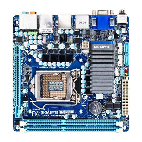
Page 7: Ga-H67N-Usb3-B3 Motherboard Layout
GA-H67N-USB3-B3 Motherboard Layout SATA2_2 SATA2_3 F_PANEL SATA3_0 SATA3_1 SYS_FAN R_SPDIF F_USB2 CLR_CMOS F_USB1 iTE IT8728 Intel ® VGA_HDMI LGA1155 USB_HDMI ATX_12V Renesas D720200 USB_ESATA Realtek RTL8111E (Note 1) USB30_LAN SPDIF_O AUDIO F_AUDIO PCIEX16 CODEC M_BIOS (Note 2) B_BIOS (Note 1) The LAN chip is located on the back of the motherboard. (Note 2) The BIOS flash ROM is located below the latch on the PCIEX16 slot.
-
Page 8: Ga-H67N-Usb3-B3 Motherboard Block Diagram
GA-H67N-USB3-B3 Motherboard Block Diagram 1 PCI Express x16 CPU CLK+/- (100 MHz) PCIe CLK LGA1155 (100 MHz) DDR3 1333/1066/800 MHz Dual Channel Memory PCI Express Bus 2 USB 3.0/2.0 RJ45 HDMI Realtek Renesas RTL8111E D720200 D-Sub PCI Express Bus Dual BIOS Intel ®…
-
Page 9: Chapter 1 Hardware Installation
Chapter 1 Hardware Installation Installation Precautions The motherboard contains numerous delicate electronic circuits and components which can become damaged as a result of electrostatic discharge (ESD). Prior to installation, carefully read the user’s manual and follow these procedures: Prior to installation, do not remove or break motherboard S/N (Serial Number) sticker or •…
-
Page 10: Product Specifications
Dual channel memory architecture Š Support for DDR3 1333/1066/800 MHz memory modules Š Support for non-ECC memory modules Š (Go to GIGABYTE’s website for the latest supported memory speeds and memory modules.) Onboard Integrated in the Chipset: Š Graphics 1 x D-Sub port…
-
Page 11
Internal 1 x 24-pin ATX main power connector Š Connectors 1 x 4-pin ATX 12V power connector Š 2 x SATA 6Gb/s connectors Š 2 x SATA 3Gb/s connectors Š 1 x CPU fan header Š 1 x system fan header Š… -
Page 12
Support for Microsoft Windows 7/Vista/XP Š ® System Form Factor Mini-ITX Form Factor; 17.0cm x 17.0cm Š * GIGABYTE reserves the right to make any changes to the product specifications and product-related in formation without prior notice. Hardware Installation — 12 -… -
Page 13: Installing The Cpu And Cpu Cooler
Read the following guidelines before you begin to install the CPU: Make sure that the motherboard supports the CPU. • (Go to GIGABYTE’s website for the latest CPU support list.) Always turn off the computer and unplug the power cord from the power outlet before installing •…
-
Page 14
B. Follow the steps below to correctly install the CPU into the motherboard CPU socket. Before installing the CPU, make sure to turn off the computer and unplug the power cord from the power outlet to prevent damage to the CPU. Step 1: Step 2: Gently press the CPU socket lever handle down… -
Page 15: Installing The Cpu Cooler
1-3-2 Installing the CPU Cooler Follow the steps below to correctly install the CPU cooler on the motherboard. (The following procedure uses Intel boxed cooler as the example cooler.) ® Male Push Direction of the Arrow Sign on The Top the Male Push of Female Push Pin…
-
Page 16: Installing The Memory
Make sure that the motherboard supports the memory. It is recommended that memory of the • same capacity, brand, speed, and chips be used. (Go to GIGABYTE’s website for the latest supported memory speeds and memory modules.) Always turn off the computer and unplug the power cord from the power outlet before installing •…
-
Page 17: Installing A Memory
1-4-2 Installing a Memory Before installing a memory module, make sure to turn off the computer and unplug the power cord from the power outlet to prevent damage to the memory module. DDR3 and DDR2 DIMMs are not compatible to each other or DDR DIMMs. Be sure to install DDR3 DIMMs on this motherboard.
-
Page 18: Installing An Expansion Card
Installing an Expansion Card Read the following guidelines before you begin to install an expansion card: Make sure the motherboard supports the expansion card. Carefully read the manual that came • with your expansion card. Always turn off the computer and unplug the power cord from the power outlet before installing •…
-
Page 19: Back Panel Connectors
Back Panel Connectors Optical S/PDIF Out Connector This connector provides digital audio out to an external audio system that supports digital optical audio. Before using this feature, ensure that your audio system provides an optical digital audio in connector. Coaxial S/PDIF Out Connector This connector provides digital audio out to an external audio system that supports digital coaxial audio.
-
Page 20
Dual Monitor Configurations for the Onboard Graphics: This motherboard provides two video output ports: D-Sub and HDMI Dual monitor configurations are supported in operating system environment only, but not during the BIOS Setup or POST process. USB 2.0/1.1 Port The USB port supports the USB 2.0/1.1 specification. Use this port for USB devices such as a USB keyboard/ mouse, USB printer, USB flash drive and etc. -
Page 21: Internal Connectors
Internal Connectors ATX_12V F_PANEL F_AUDIO CPU_FAN F_USB1/F_USB2 SYS_FAN SPDIF_O CLR_CMOS SATA3_0/1 PHASE LED SATA2_2/3 Read the following guidelines before connecting external devices: First make sure your devices are compliant with the connectors you wish to connect. • Before installing the devices, be sure to turn off the devices and your computer. Unplug the •…
-
Page 22
1/2) ATX_12V/ATX (2×2 12V Power Connector and 2×12 Main Power Connector) With the use of the power connector, the power supply can supply enough stable power to all the components on the motherboard. Before connecting the power connector, first make sure the power supply is turned off and all devices are properly installed. -
Page 23: Bat Battery
3/4) CPU_FAN/SYS_FAN (Fan Headers) The motherboard has a 4-pin CPU fan header (CPU_FAN) and a 3-pin system fan header (SYS_FAN). Most fan headers possess a foolproof insertion design. When connecting a fan cable, be sure to connect it in the correct orientation (the black connector wire is the ground wire). The motherboard supports CPU fan speed control, which requires the use of a CPU fan with fan speed control design.
-
Page 24
6) SATA3_0/1 (SATA 6Gb/s Connectors, Controlled by Intel H67 Chipset) The SATA connectors conform to SATA 6Gb/s standard and are compatible with SATA 3Gb/s and SATA 1.5Gb/s standard. Each SATA connector supports a single SATA device. The SATA3_0 and SATA3_1 connectors support RAID 0 and RAID 1. -
Page 25: F_Panel (Front Panel Header)
 F_PANEL (Front Panel Header) Connect the power switch, reset switch, and system status indicator on the chassis to this header ac- cording to the pin assignments below. Note the positive and negative pins before connecting the cables. Reset Ha rd Dr i v e Activity LED Switch Power…
 -
Page 26: Front Panel Audio Header
9) F_AUDIO (Front Panel Audio Header) The front panel audio header supports Intel High Definition audio (HD) and AC’97 audio. You may connect your chassis front panel audio module to this header. Make sure the wire assignments of the module con- nector match the pin assignments of the motherboard header.
-
Page 27: S/Pdif Out Header
11) SPDIF_O (S/PDIF Out Header) This header supports digital S/PDIF Out and connects a S/PDIF digital audio cable (provided by expan- sion cards) for digital audio output from your motherboard to certain expansion cards like graphics cards and sound cards. For example, some graphics cards may require you to use a S/PDIF digital audio cable for digital audio output from your motherboard to your graphics card if you wish to connect an HDMI display to the graphics card and have digital audio output from the HDMI display at the same time.
-
Page 28
13) PHASE LED The number of lighted LEDs indicates the CPU loading. The higher the CPU loading, the more the number of lighted LEDs. To enable the Phase LED display function, please first enable Dynamic Energy Saver 2. Refer to Chapter 4, «Dynamic Energy Saver 2,»… -
Page 29: Chapter 2 Bios Setup
To see more advanced BIOS Setup menu options, you can press <Ctrl> + <F1> in the main menu of the BIOS Setup program. To upgrade the BIOS, use either the GIGABYTE Q-Flash or @BIOS utility. Q-Flash allows the user to quickly and easily upgrade or back up BIOS without entering the operating •…
-
Page 30: Startup Screen
Startup Screen The following screens may appear when the computer boots. A. The LOGO Screen (Default) Function Keys B. The POST Screen Award Modular BIOS v6.00PG Copyright (C) 1984-2011, Award Software, Inc. H67N-USB3-B3 F3a Motherboard Model BIOS Version Function Keys <DEL>: BIOS Setup <F9>: XpressRecovery2 <F12>: Boot Menu <End>: Qflash 03/11/2011-H67-7A89UG0PC-00 SATA Mode Message:…
-
Page 31: The Main Menu
The Main Menu Once you enter the BIOS Setup program, the Main Menu (as shown below) appears on the screen. Use ar- row keys to move among the items and press <Enter> to accept or enter a sub-menu. (Sample BIOS Version: F3a) CMOS Setup Utility-Copyright (C) 1984-2011 Award Software MB Intelligent Tweaker(M.I.T.) Load Fail-Safe Defaults…
-
Page 32
The Functions of the <F11> and <F12> keys (For the Main Menu Only) F11: Save CMOS to BIOS This function allows you to save the current BIOS settings to a profile. You can create up to 8 profiles (Profile 1-8) and name each profile. -
Page 33: Mb Intelligent Tweaker(M.i.t.)
MB Intelligent Tweaker(M.I.T.) CMOS Setup Utility-Copyright (C) 1984-2011 Award Software MB Intelligent Tweaker(M.I.T.) Item Help M.I.T Current Status [Press Enter] Menu Level Advanced Frequency Settings [Press Enter] Advanced Memory Settings [Press Enter] Advanced Voltage Settings [Press Enter] …
-
Page 34: Cpu Clock Ratio
M.I.T. Current Status This screen provides information on CPU/memory frequencies/parameters. Advanced Frequency Settings CMOS Setup Utility-Copyright (C) 1984-2011 Award Software Advanced Frequency Settings Item Help CPU Clock Ratio [30X] Menu Level CPU Frequency 3.00GHz (100×30) Advanced CPU Core Features [Press Enter] >>>>>…
-
Page 35
Intel(R) Turbo Boost Tech. (Note) Allows you to determine whether to enable the Intel CPU Turbo Boost technology. Auto lets the BIOS automatically configure this setting. (Default: Auto) Turbo Ratio (1-Core)/(2-Core)/(3-Core)/(4-Core) (Note) Allows you to set the CPU Turbo ratios for different number of active cores. Auto sets the CPU Turbo ratios according to the CPU specifications. -
Page 36
Bi-Directional PROCHOT (Note) Auto Lets the BIOS automatically configure this setting. (Default) Enabled When the CPU or chipset detects that an overheating is occurring, PROCHOT signals will be emitted to lower CPU performance to decrease heat production. Disabled Only allows the CPU to detect whether an overheating is occurring to emit PROCHOT sig- nals. -
Page 37
Advanced Memory Settings CMOS Setup Utility-Copyright (C) 1984-2011 Award Software Advanced Memory Settings Item Help System Memory Multiplier (SPD) [Auto] Menu Level Memory Frequency (Mhz) 1333 1333 Performance Enhance [Turbo] DRAM Timing Selectable (SPD) [Auto] Profile DDR Voltage 1.5V Profile VTT Voltage 1.05V x Channel Interleaving Auto x Rank Interleaving… -
Page 38
>>>>> Channel A/B Timing Settings CMOS Setup Utility-Copyright (C) 1984-2011 Award Software Channel A Timing Settings Item Help >>>>> Channel A Standard Timing Control Menu Level x CAS Latency Time Auto x tRCD Auto x tRP Auto x tRAS Auto >>>>>… -
Page 39
tFAW Options are: Auto (default), 1~63. Command Rate(CMD) Options are: Auto (default), 1~3. >>>>> Channel A/B Misc Timing Control IO Latency Options are: Auto (default), 1~31. Round Trip Latency Options are: Auto (default), 1~255. Advanced Voltage Settings CMOS Setup Utility-Copyright (C) 1984-2011 Award Software Advanced Voltage Settings Item Help ****** Mother Board Voltage Control ******… -
Page 40: Miscellaneous Settings
Miscellaneous Settings CMOS Setup Utility-Copyright (C) 1984-2011 Award Software Miscellaneous Settings Item Help Isochronous Support [Enabled] Menu Level Virtualization Technology (Note) [Enabled] hi: Move Enter: Select +/-/PU/PD: Value F10: Save ESC: Exit F1: General Help F5: Previous Values F6: Fail-Safe Defaults F7: Optimized Defaults Isochronous Support Determines whether to enable specific streams within the CPU and Chipset.
-
Page 41: Standard Cmos Features
Standard CMOS Features CMOS Setup Utility-Copyright (C) 1984-2011 Award Software Standard CMOS Features Item Help Date (mm:dd:yy) Tue, Jan 27 2011 Menu Level Time (hh:mm:ss) 10:26:46 IDE Channel 0 Master [None] IDE Channel 0 Slave [None] IDE Channel 1 Master [None] …
-
Page 42
Landing Zone Landing zone. Sector Number of sectors. Halt On Allows you to determine whether the system will stop for an error during the POST. All Errors Whenever the BIOS detects a non-fatal error the system boot will stop. (Default) No Errors The system boot will not stop for any error. -
Page 43: Advanced Bios Features
Advanced BIOS Features CMOS Setup Utility-Copyright (C) 1984-2011 Award Software Advanced BIOS Features Item Help Hard Disk Boot Priority [Press Enter] Menu Level Quick Boot [Disabled] EFI CD/DVD Boot Option [Auto] First Boot Device [Hard Disk] Second Boot Device [CDROM] Third Boot Device [USB-FDD]…
-
Page 44
Allows you to set a delay time for the BIOS to initialize the hard drive as the system boots up. The ad- justable range is from 0 to 15 seconds. (Default: 0) Full Screen LOGO Show Allows you to determine whether to display the GIGABYTE Logo at system startup. Disabled displays normal POST message. (Default: Enabled) Init Display First Specifies the first initiation of the monitor display from the installed PCI Express graphics card or the onboard graphics. -
Page 45: Integrated Peripherals
Enables or disables the X.H.D function for the SATA controllers integrated in the Intel H67 Chipset. When set to Enabled, the PCH SATA Control Mode item below will be set to RAID(XHD) automatically. For details on using the GIGABYTE X.H.D utility, refer to Chaper 4, «eXtreme Hard Drive (X.H.D).» (Default: Disabled)
-
Page 46
Azalia Codec Enables or disables the onboard audio function. (Default: Auto) If you wish to install a 3rd party add-in audio card instead of using the onboard audio, set this item to Disabled. Onboard H/W LAN Enables or disables the onboard LAN function. (Default: Enabled) If you wish to install a 3rd party add-in network card instead of using the onboard LAN, set this item to Disabled. -
Page 47: Power Management Setup
Power Management Setup CMOS Setup Utility-Copyright (C) 1984-2011 Award Software Power Management Setup Item Help ACPI Suspend Type [S3(STR)] Menu Level Soft-Off by PWR-BTTN [Instant-Off] PME Event Wake Up [Enabled] Resume by Alarm [Disabled] Date (of Month) Alarm Everyday Time (hh:mm:ss) Alarm 0 : 0 : 0 HPET Support [Enabled]…
-
Page 48
HPET Support (Note) Enables or disables High Precision Event Timer (HPET) for Windows 7/Vista operating system. (Default: Enabled) HPET Mode (Note) Allows you to select the HPET mode for your Windows 7/Vista operating system. Select 32-bit mode when you install 32-bit Windows 7/Vista; select 64-bit mode when you install 64-bit Windows 7/Vista. This item is configurable only when the HPET Support is set to Enabled. -
Page 49: Pc Health Status
PC Health Status CMOS Setup Utility-Copyright (C) 1984-2011 Award Software PC Health Status Item Help Vcore 1.172V Menu Level DDR15V 1.516V +12V 11.779V 1.076V Current System Temperature Current CPU Temperature Current CPU FAN Speed 3375 RPM Current SYSTEM FAN Speed 0 RPM CPU Smart FAN Control [Normal]…
-
Page 50: Load Fail-Safe Defaults
Load Fail-Safe Defaults CMOS Setup Utility-Copyright (C) 1984-2011 Award Software MB Intelligent Tweaker(M.I.T.) Load Fail-Safe Defaults Standard CMOS Features Load Optimized Defaults Advanced BIOS Features Set Supervisor Password Integrated Peripherals Set User Password Power Management Setup Save &…
-
Page 51: Set Supervisor/User Password
2-11 Set Supervisor/User Password CMOS Setup Utility-Copyright (C) 1984-2011 Award Software MB Intelligent Tweaker(M.I.T.) Load Fail-Safe Defaults Standard CMOS Features Load Optimized Defaults Advanced BIOS Features Set Supervisor Password Integrated Peripherals Set User Password Power Management Setup Save &…
-
Page 52: Save & Exit Setup
2-12 Save & Exit Setup CMOS Setup Utility-Copyright (C) 1984-2011 Award Software MB Intelligent Tweaker(M.I.T.) Load Fail-Safe Defaults Standard CMOS Features Load Optimized Defaults Save to CMOS and EXIT (Y/N)? Y Advanced BIOS Features Set Supervisor Password Integrated Peripherals Set User Password …
-
Page 53: Chapter 3 Drivers Installation
After «Xpress Install» installs all of the drivers, a dialog box will appear asking whether to install • new GIGABYTE utilities. Click Yes to automatically install the utilities. Or click No if you want to manually select the utilities to install on the Application Software page later.
-
Page 54: Application Software
Application Software This page displays all the utilities and applications that GIGABYTE develops and some free software. You can click the Install button on the right of an item to install it. Technical Manuals This page provides GIGABYTE’s application guides, content descriptions for this driver disk, and the mother- board manuals.
-
Page 55: Contact
Contact For the detailed contact information of the GIGABYTE Taiwan headquarter or worldwide branch offices, click the URL on this page to link to the GIGABYTE website. System This page provides the basic system information. — 55 — Drivers Installation…
-
Page 56: Download Center
The latest version of the BIOS, drivers, or applications will be displayed. New Utilities This page provides a quick link to GIGABYTE’s lately developed utilities for users to install. You can click the Install button on the right of an item to install it.
-
Page 57: Chapter 4 Unique Features
Chapter 4 Unique Features Xpress Recovery2 Xpress Recovery2 is a utility that allows you to quickly compress and back up your system data and perform restoration of it. Supporting NTFS, FAT32, and FAT16 file systems, Xpress Recovery2 can back up data on PATA and SATA hard drives and restore it.
-
Page 58
Step 3: Step 4: When partitioning your hard drive, make sure to After the operating system is installed, click Start, leave unallocated space (10 GB or more is recom- right-click the Computer and select Manage. Go to mended; actual size requirements vary, depending Disk Management to check disk allocation. -
Page 59
D. Using the Restore Function in Xpress Recovery2 Select RESTORE to restore the backup to your hard drive in case the system breaks down. The RESTORE option will not be present if no backup is created before. E. Removing the Backup Step 1: Step 2: If you wish to remove the backup file, select… -
Page 60: Bios Update Utilities
4-2-1 Updating the BIOS with the Q-Flash Utility A. Before You Begin From GIGABYTE’s website, download the latest compressed BIOS update file that matches your moth- erboard model. Extract the file and save the new BIOS file (e.g. h67nusb3.f3) to your USB flash drive, or hard drive.
-
Page 61
B. Updating the BIOS When updating the BIOS, choose the location where the BIOS file is saved. The following procedure as- sumes that you save the BIOS file to a USB flash drive. Step 1: Insert the USB flash drive containing the BIOS file into the computer. In the main menu of Q-Flash, use the up or down arrow key to select Update BIOS from Drive and press <Enter>. -
Page 62
Step 4: Press <Esc> and then <Enter> to exit Q-Flash and reboot the system. As the system boots, you should see the new BIOS version is present on the POST screen. Step 5: During the POST, press <Delete> to enter BIOS Setup. Select Load Optimized Defaults and press <Enter> to load BIOS defaults. -
Page 63: Updating The Bios With The @Bios Utility
BIOS or a system that is unable to start. Do not use the G.O.M. (GIGABYTE Online Management) function when using @BIOS. GIGABYTE product warranty does not cover any BIOS damage or system failure resulting from an inad- equate BIOS flashing.
-
Page 64: Easytune 6
EasyTune 6 GIGABYTE’s EasyTune 6 is a simple and easy-to-use interface that allows users to fine-tune their system settings or do overclock/overvoltage in Windows environment. The user-friendly EasyTune 6 interface also includes tabbed pages for CPU and memory information, letting users read their system-related information without the need to install additional software.
-
Page 65: Dynamic Energy Saver ™ 2
The Dynamic Energy Saver 2 Interface ™ A. Meter Mode In Meter Mode, GIGABYTE Dynamic Energy Saver 2 shows how much power they have saved in a set pe- ™ riod of time. 12 13 14…
-
Page 66
B. Total Mode In Total Mode, users are able to see how much total power savings they have accumulated in a set period of time since activating Dynamic Energy Saver 2 for the first time ™ (Note 3) 11 12 13 Total Mode — Button Information Table Button Description Dynamic Energy Saver On/Off Switch (Default: Off) -
Page 67: Q-Share
Q-Share, you are able to share your data with computers on the same network, making full use of Internet resources. Directions for using Q-Share After installing Q-Share from the motherboard driver disk, go to Start>All Programs>GIGABYTE>Q-Share. exe to launch the Q-Share tool. Find the Q-Share icon in the notification area and right-click on this icon to configure the data sharing settings.
-
Page 68: Smart 6
Smart 6 ™ GIGABYTE Smart 6 is designed with user-friendliness in mind, and offers a combination of 6 innovative ™ (Note 1) software utilities that provide easier and smarter PC system management. Smart 6 allows you to speed up ™…
-
Page 69
SMART Recovery 2 Smart Recovery 2 allows you to back up a partition as an image file every hour. You can use these images to restore your system or files when needed. The Smart Recovery 2 main menu: Button Function Settings Allows you to select the source and destination partition Backup Now… -
Page 70
Recovering your system with Smart Recovery 2 (Windows 7 only): Steps: 1. Click the System Recovery button on the main menu. 2. Select the partition where your backup is saved. 3. Use the time slider to select a time point. 4. -
Page 71
SMART Recorder SMART Recorder monitors and records the activities in a system such as the time when the computer was turned on/off or even when large data files were moved within the hard drive or copied to an external storage device (Note 2) Instructions: Select the Enable check box at the bottom of the ON/OFF Recorder… -
Page 72: Auto Green
Auto Green Auto Green is an easy-to-use tool that provides users with simple options to enable system power savings via a Bluetooth cell phone. When the phone is out of the range of the computer’s Bluetooth receiver, the sys- tem will enter the specified power saving mode. The Configuration dialog box: First, you have to set your Bluetooth cell phone as a portable key.
-
Page 73: Extreme Hard Drive (X.h.d)
After installing the operating system, insert the motherboard driver disk. You can click the Xpress Install All button to automatically install all motherboard drivers, including the X.H.D utility. Or you can go to the Applica- tion Software screen to individually install the X.H.D utility later. B. Using GIGABYTE eXtreme Hard Drive (X.H.D) Instructions: (Note 2) Before launching X.H.D, make sure the newly added hard-…
-
Page 74: Cloud Oc
Cloud OC Cloud OC is an easy-to-use overclocking utility designed for system overclock- (Note 1) ing via virtually any Internet-connected device, such as a smart phone, iPhone, note- book PC, etc. By simply connecting to an Internet browser via LAN, wireless LAN, or Bluetooth and logging in to the Cloud OC server, you can easily access three major functions of Cloud (Note 2)
-
Page 75: Chapter 5 Appendix
Chapter 5 Appendix Configuring SATA Hard Drive(s) To configure SATA hard drive(s), follow the steps below: A. Install SATA hard drive(s) in your computer. B. Configure SATA controller mode in BIOS Setup. C. Configure a RAID array in RAID BIOS. (Note 1) D.
-
Page 76
B. Configuring SATA controller mode in BIOS Setup Make sure to configure the SATA controller mode correctly in system BIOS Setup. Step 1: Turn on your computer and press <Delete> to enter BIOS Setup during the POST (Power-On Self-Test). To create RAID, set PCH SATA Control Mode under the Integrated Peripherals menu to RAID(XHD) (Figure 1) (IDE by default). -
Page 77
C. Configuring a RAID array in RAID BIOS Enter the RAID BIOS setup utility to configure a RAID array. Skip this step and proceed with the installation of Windows operating system for a non-RAID configuration. Step 1: After the POST memory test begins and before the operating system boot begins, look for a message which says «Press <Ctrl-I>… -
Page 78
Step 3: After entering the CREATE VOLUME MENU screen, enter a volume name with 1~16 letters (letters cannot be special characters) under the Name item and press <Enter>. Then, select a RAID level (Figure 4). RAID levels supported include RAID 0, RAID 1, Recovery, RAID 10, and RAID 5 (the selections available depend on the number of the hard drives being installed). -
Page 79
Step 5: Enter the array capacity and press <Enter>. Finally press <Enter> on the Create Volume item to begin creat- ing the RAID array. When prompted to confirm whether to create this volume, press <Y> to confirm or <N> to cancel (Figure 6). -
Page 80
Recovery Volume Options Intel Rapid Recover Technology provides data protection by allowing users to easily restore data and system operation using a designated recovery drive. With the Rapid Recovery Technology, which employs RAID 1 functionality, users can copy the data from the master drive to the recovery drive; if needed, the data on the recovery drive can be restored back to the master drive. -
Page 81
Step 3: Press <Enter> under the Select Disks item. In the SELECT DISKS box, press <Tab> on the hard drive you want to use for the master drive and press <Space> on the hard drive you want to use for the recovery drive. (Make sure the recovery drive has equal or larger capacity than the master drive.) Then press <Enter>… -
Page 82
Delete RAID Volume To delete a RAID array, select Delete RAID Volume in MAIN MENU and press <Enter>. In the DELETE VOLUME MENU section, use the up or down arrow key to select the array to be deleted and press <Delete>. When prompted to confirm your selection (Figure 12), press <Y>… -
Page 83: Installing The Sata Raid/Ahci Driver And Operating System
5-1-2 Installing the SATA RAID/AHCI Driver and Operating System With the correct BIOS settings, you are ready to install Windows 7/Vista/XP onto your hard drive(s). A. Installing Windows XP To install Windows XP, you need to install the SATA RAID/AHCI controller driver during the OS installation. Without the driver, the hard drive(s) may not be recognized during the Windows setup process.
-
Page 84
C. Rebuilding an Array Rebuilding is the process of restoring data to a hard drive from other drives in the array. Rebuilding applies only to fault-tolerant arrays such as RAID 1, RAID 5 or RAID 10 arrays. The procedures below assume a new drive is added to replace a failed drive to rebuild a RAID 1 array. -
Page 85
• Performing the Rebuild in the Operating System While in the operating system, make sure the chipset driver has been installed from the motherboard driver disk. Then launch the Intel Rapid Storage Technology utility from All Programs in the Start menu. Step 2: Select a new drive to rebuild the RAID and click Rebuild. -
Page 86
• Restoring the Master Drive to a Previous State (for Recovery Volume only) When two hard drives are set to Recovery Volume in Update on Request mode, you can restore the master drive data to the last backup state when needed. For example, in case the master drive detects a virus, you can restore the recovery drive data to the master drive. -
Page 87: Configuring Audio Input And Output
Configuring Audio Input and Output 5-2-1 Configuring 2/4/5.1/7.1-Channel Audio The motherboard provides six audio jacks on the back panel which support 2/4/5.1/7.1-channel audio. (Note) The picture to the right shows the default audio jack Center/Subwoofer Line In Speaker Out assignments. Rear Speaker Out Front Speaker Out The integrated HD (High Definition) audio provides…
-
Page 88
Step 2: Connect an audio device to an audio jack. The The cur- rent connected device is dialog box appears. Select the device according to the type of device you connect. Then click OK. Step 3: On the Speakers screen, click the Speaker Configura- tion tab. -
Page 89: Configuring S/Pdif Out
5-2-2 Configuring S/PDIF Out The S/PDIF Out jack can transmit audio signals to an external decoder for decoding to get the best audio quality. 1. Connecting a S/PDIF Out Cable: Connect a S/PDIF coaxial cable or a S/PDIF optical cable (either one) to the corresponding S/PDIF out con- nector as shown below and an external decoder for transmitting the S/PDIF digital audio signals.
-
Page 90: Enabling The Dolby Home Theater Function
5-2-3 Enabling the Dolby Home Theater Function Before Dolby Home Theater is enabled, you get only 2-channel playback output (from the front speakers) when playing 2-channel stereo sources. You must play 4-, 5.1-, or 7.1- chan- nel content to get 4-, 5.1-, or 7.1- channel audio effects. With Dolby Home Theater enabled, 2-channel stereo content will be transformed into multi-channel audio, creating a virtual sur- round sound environment.
-
Page 91: Configuring Microphone Recording
5-2-4 Configuring Microphone Recording Step 1: After installing the audio driver, the HD Audio Manager icon will appear in the notification area. Double-click the icon to access the HD Audio Manager. Step 2: Connect your microphone to the Mic in jack (pink) on the back panel or the Mic in jack (pink) on the front panel.
-
Page 92
Step 5: After completing the settings above, click Start, point to All Programs, point to Accessories, and then click Sound Recorder to begin the sound recording. * Enabling Stereo Mix If the HD Audio Manager does not display the recording device you wish to use, refer to the steps below. The following steps explain how to enable Stereo Mix (which may be needed when you want to record sound from your computer). -
Page 93: Using The Sound Recorder
Step 4: Now you can access the HD Audio Manager to config- ure Stereo Mix and use Sound Recorder to record the sound. 5-2-5 Using the Sound Recorder A. Recording Sound 1. Make sure you have connected the sound input device (e.g. microphone) to the computer. 2.
-
Page 94: Troubleshooting
Troubleshooting 5-3-1 Frequently Asked Questions To read more FAQs for your motherboard, please go to the Support & DownloadsFAQ page on GIGABYTE’s website. Q: In the BIOS Setup program, why are some BIOS options missing? A: Some advanced options are hidden in the BIOS Setup program. Press <Delete> to enter BIOS Setup during the POST. In the Main Menu, press <Ctrl>+<F1>…
-
Page 95: Troubleshooting Procedure
5-3-2 Troubleshooting Procedure If you encounter any troubles during system startup, follow the troubleshooting procedure below to solve the problem. START Turn off the power. Remove all peripherals, connecting cables, and power cord etc. Make sure the motherboard does not short-circuit with the chassis or Isolate the short circuit.
-
Page 96
The power supply, CPU or When the computer is turned on, is the CPU cooler running? CPU socket might fail. The problem is verified and solved. The graphics card, expansion slot, or monitor Check if there is display on your monitor. might fail. -
Page 97
— 97 — Appendix… -
Page 98
Appendix — 98 -… -
Page 99
Web address: http://latam.giga-byte.com TEL: +86-24-83992901 • Giga-Byte SINGAPORE PTE. LTD. — Singapore FAX: +86-24-83992909 WEB address : http://www.gigabyte.sg • GIGABYTE TECHNOLOGY (INDIA) LIMITED — India • Thailand WEB address : http://www.gigabyte.in WEB address : http://th.giga-byte.com • Saudi Arabia • Vietnam WEB address : http://www.gigabyte.com.sa… -
Page 100
WEB address : http://www.gigabyte.com.gr WEB address : http://www.gigabyte.kz • Czech Republic You may go to the GIGABYTE website, select your language WEB address : http://www.gigabyte.cz in the language list on the top right corner of the website. • GIGABYTE Global Service System…
 F_PANEL (Front Panel Header) Connect the power switch, reset switch, and system status indicator on the chassis to this header ac- cording to the pin assignments below. Note the positive and negative pins before connecting the cables. Reset Ha rd Dr i v e Activity LED Switch Power…
 Connect the power switch, reset switch, and system status indicator on the chassis to this header ac-
cording to the pin assignments below. Note the positive and negative pins before connecting the cables.
MSG
(Message/Sleep LED, Yellow):
•
System Status LED
S0
On
S1
Blinking
S3/S4/S5
Off
PW
(Power Switch, Red):
•
Connects to the power switch on the chassis front panel. You may configure the way to turn off your
system using the power switch (refer to Chapter 2, «BIOS Setup,» «Power Management Setup,» for
more information).
HD
(Hard Drive Activity LED, Blue)
•
Connects to the hard drive activity LED on the chassis front panel. The LED is on when the hard drive
is reading or writing data.
RES
(Reset Switch, Green):
•
Connects to the reset switch on the chassis front panel. Press the reset switch to restart the computer
if the computer freezes and fails to perform a normal restart.
NC
(Purple):
•
No connection.
The front panel design may differ by chassis. A front panel module mainly consists of power
switch, reset switch, hard drive activity LED and etc. When connecting your chassis front panel
module to this header, make sure the wire assignments and the pin assignments are matched
correctly.
Connects to the power status indicator on the chassis front panel. The LED
is on when the system is operating. The LED keeps blinking when the sys-
tem is in S1 sleep state. The LED is off when the system is in S3/S4 sleep
state or powered off (S5).
— 25 —
Reset
Ha rd Dr i v e
Activity LED
Switch
1
9
2
10
Power
Message/Sleep
Switch
LED
Hardware Installation
-
Драйверы
41
-
Инструкции по эксплуатации
10
Языки:

Gigabyte GA-H67N-USB3-B3 инструкция по эксплуатации
(72 страницы)
- Языки:Венгерский, Греческий, Испанский, Итальянский, Немецкий, Польский, Португальский, Русский, Турецкий, Французский, Чешский
-
Тип:
PDF -
Размер:
18.6 MB -
Описание:
Installation Guidebook


На NoDevice можно скачать инструкцию по эксплуатации для Gigabyte GA-H67N-USB3-B3. Руководство пользователя необходимо для ознакомления с правилами установки и эксплуатации Gigabyte GA-H67N-USB3-B3. Инструкции по использованию помогут правильно настроить Gigabyte GA-H67N-USB3-B3, исправить ошибки и выявить неполадки.
Посмотреть инструкция для Gigabyte GA-H67N-USB3-B3 бесплатно. Руководство относится к категории материнские платы, 1 человек(а) дали ему среднюю оценку 7.5. Руководство доступно на следующих языках: английский. У вас есть вопрос о Gigabyte GA-H67N-USB3-B3 или вам нужна помощь? Задайте свой вопрос здесь
- Box Contents
- Optional Items
- GA-H67N-USB3-B3 Motherboard Layout
- GA-H67N-USB3-B3 Motherboard Block Diagram
- Chapter 1 Hardware Installation
- Chapter 2 BIOS Setup
- Chapter 3 Drivers Installation
- Chapter 4 Unique Features
- Chapter 5 Appendix
Главная
| Gigabyte | |
| GA-H67N-USB3-B3 | GA-H67N-USB3-B3 | |
| материнская плата | |
| 4719331807283 | |
| английский | |
| Руководство пользователя (PDF), Инструкция по установке (PDF) |
Память
| Error-correcting code (ECC) | Нет |
| без функции коррекции ошибок | Да |
| Максимальная внутренняя память | 16 GB |
| Количество слотов памяти | 2 |
| Напряжение памяти | 1.5 V |
| Поддерживаемые частоты памяти | 800,1066,1333 MHz |
Процессор
| Производитель процессора | Intel |
| Сокет процессора | LGA 1155 (Socket H2) |
| Совместимые серии процессоров | Intel Core i3, Intel Core i5, Intel Core i7 |
| Скорость передачи данных системной шины | 5 GT/s |
Внутренние порты
| Разъемы USB 2.0 | 2 |
| Разъем выхода S/PDIF | Да |
| Разъем вентилятора центрального процессора | Да |
| Разъем питания ATX (24-конт.) | Да |
| Количество разъемов питания EATX | 1 |
| Разъем Chassis intrusion | Да |
| Количество параллельных разъемов ATA (PATA) | 0 |
| Аудиоразъем передней панели | Да |
| Количество разъемов SATA II | 2 |
| Количество разъемов SATA III | 2 |
Порты на задней панели
| Количество портов PS/2 | 0 |
| Количество портов USB 2.0 | 4 |
| Порты FireWire | 0 |
| Количество портов Ethernet LAN ( RJ-45) | 1 |
| Линейные выходы наушников | 6 |
| Линейный вход микрофона | Да |
| Порт выхода S/PDIF | Да |
| Количество портов VGA (D-Sub) | 1 |
| Количество портов eSATA | 1 |
| Количество портов DVI-D | 0 |
| Цифровой оптический аудио выход | 1 |
| Количество HDMI портов | 2 |
| Количество портов USB 3.2 Gen 1 (3.1 Gen 1) Type-A | 2 |
Свойства
| Формат материнской платы | Mini ITX |
| Совместимые операционные системы | Windows 7/Vista/XP |
| Комплектующие для | ПК |
| Аудио чип | Realtek ALC889 |
| Выходные звуковые каналы | 7.1 канала |
| Тип источника питания | ATX |
Графический адаптер
| Поддержка технологии параллельной обработки | Не поддерживается |
| Объём памяти графического адаптера | 1748 MB |
| Видеокарта | — |
| HDCP | Да |
| Встроенный графический адаптер | Да |
| Семейство графического адаптера | Intel |
Слоты расширения
| PCI Express x16 слоты | 1 |
| Версия PCI Express слотов | 2.0 |
Вес и размеры
| Ширина | 170 mm |
| Глубина | 170 mm |
Контроллеры хранения данных
Прочие свойства
| Краткое руководство по установке | Да |
Содержимое упаковки
Сеть
| Характеристики сети | 10/100/1000 Mbit/sec |
| Контроллер LAN | Realtek RTL8111E |
| Тип Ethernet интерфейса | Гигабитный Ethernet |
BIOS
| Тип BIOS | AWARD |
| Размер памяти BIOS | 32 Mbit |
| Версия ACPI | 1.0b |
показать больше
Не можете найти ответ на свой вопрос в руководстве? Вы можете найти ответ на свой вопрос ниже, в разделе часто задаваемых вопросов о Gigabyte GA-H67N-USB3-B3.
Какая ширина Gigabyte GA-H67N-USB3-B3?
Какая толщина Gigabyte GA-H67N-USB3-B3?
Инструкция Gigabyte GA-H67N-USB3-B3 доступно в русский?
Не нашли свой вопрос? Задайте свой вопрос здесь
Перейти к контенту
Материнские платы Gigabyte

- Размер инструкции: 25.22 Мб
- Формат файла: pdf
Если вы потеряли инструкцию от материнской платы Gigabyte GA H67N USB3 B3 rev 1 0, можете скачать файл для просмотра на компьютере или печати.
Инструкция для материнской платы Gigabyte GA H67N USB3 B3 rev 1 0 на русском языке. В руководстве описаны возможности и полезные функции, а также правила эксплуатации. Перед использованием внимательно ознакомьтесь с инструкцией.
Чтобы не читать всю инструкцию вы можете выполнить поиск по содержимому внутри инструкции и быстро найти необходимую информацию. Рекомендации по использованию помогут увеличить срок службы материнской платы Gigabyte GA H67N USB3 B3 rev 1 0. Если у вас появилась проблема, то найдите раздел с описанием неисправностей и способами их решения. В нем указаны типичные поломки и способы их решения.