- Manuals
- Brands
- DoorHan Manuals
- Gate Opener
- Sectional-500
- Installation and operating manual
Operator
-
Contents
-
Table of Contents
-
Troubleshooting
-
Bookmarks
Quick Links
OPERATOR
SECTIONAL-500//DIY-500
Installation and Operating Manual
© DoorHan, 2013
CONTENTS
GENERAL INFORMATION
SAFETY INSTRUCTIONS
OPERATOR UNIT
OPERATOR INSTALLATION
ELECTRICAL CONNECTIONS
MANUAL OPENING
MAINTENANCE
TROUBLESHOOTING
APPENDIX
2
2
4
5
6
8
13
13
14
15
Related Manuals for DoorHan Sectional-500
Summary of Contents for DoorHan Sectional-500
-
Page 1
CONTENTS GENERAL INFORMATION SAFETY INSTRUCTIONS OPERATOR UNIT OPERATOR INSTALLATION ELECTRICAL CONNECTIONS MANUAL OPENING MAINTENANCE TROUBLESHOOTING APPENDIX OPERATOR SECTIONAL-500//DIY-500 Installation and Operating Manual © DoorHan, 2013… -
Page 2: Table Of Contents
APPENDIX ………………15 1. GENERAL INFORMATION The Sectional-500/DIY-500 electromechanical chain operator is designed for automation of residential sectional doors. It consists of a mechanical gear and an electric engine with a built-in control unit. The gear and the electric engine are incorporated into a housing.
-
Page 3: Specifications
ПРАВИЛА БЕЗОПАСНОСТИ УСТРОЙСТВО ПРИВОДА УСТАНОВКА ПРИВОДА ЭЛЕКТРИЧЕСКИЕ ПОДКЛЮЧЕНИЯ ПРОГРАММИРОВАНИЕ ЭЛЕКТРОПРИВОДА ПРОГРАММИРОВАНИЕ ПУЛЬТА ДУ РУЧНОЕ ОТКРЫВАНИЕ ПРИВОД ОБСЛУЖИВАНИЕ ДИАГНОСТИКА НЕИСПРАВНОСТЕЙ SECTIONAL 500/500PRO/DIY 500 Инструкция по монтажу и эксплуатации © DoorHan, 2012 Guide fastening bracket Headroom bracket Straight arm fastening bracket Slotted bushing Fastening set № Name Quantity № Name Quantity…
-
Page 4: Safety Instructions
You should power off when performing installation, cleaning or maintenance of the operator. W hen mounting the operator on doors with the infitting pass door, it is necessary to install an additional safety device, which prevents the operator activation, when the door is open. M ake sure, that there will not be trapping of articles between movable and fixed elements of the operator when the doors move. Y ou should use additional DoorHan accessories, since the accessories of third party manufacturers can damage the automatic system. D oorHan is not liable for unstable work of the automatic system, if you use safety devices and accessories, produced by other manufacturers without securing approval of DoorHan. Y ou should not leave electric engines in a released state. This can lead to uncontrolled movement of the door wings and, as a result, to their damage. Y ou should not use the operator, if it is necessary to repair or to adjust the equipment, since defects during the assembly …
-
Page 5: Operator Unit
OPERATOR UNIT RISK OF INJURY! WARNING! Have a qualified technician lay the cables 230 V AC. The cables must be laid in protective corrugated tubes. In case of supply cable damage, use the suitable type of the cable. Cables needed for installation of sectional-500 operator and accessories (if available) Cable 2 × 0.5 mm (photocell transmitter) Cabel 4 × 0.5 mm (photocell receiver) Cable 3 × 1.5 mm (power supply) The cables should be appropriately insulated 3. OPERATOR UNIT Sectional-500 Sectional-DIY-500 Housing cover Display (for Se-500/500PRO models) Control board Motor reducer Lamp/LED lamp for Se-500PRO/DIY-500 model Lamp housing Housing Splined bushing Reference point microswitch…
-
Page 6: Operator Installation
OPERATOR INSTALLATION 4. OPERATOR INSTALLATION 4.1. TOOLS Set of spanners Set of drills for concrete Electric drill Set of slotted and cross screwdrivers Pliers Tape measure (folding rule) Set of drills for metal Hacksaw for metal 4.2. REQUIRMENTS TO DOOR INSTALLATION 45 mm P rior to installation check if the door is properly balanced and moves smoothly when automatically operated. M ake sure, that minimal clearance between …
-
Page 7: Track Installation
OPERATOR INSTALLATION 4.4. TRACK INSTALLATION The operator suspension height is determined by the maximum lift of upper edge of the door leaf. After preliminary assembly (see p. 4.3) you can start to install the track: 1. If it is required to shorten a guide, it is necessary to fulfill operations, described in Appendix 1. 1.1. For conducting a guide assembly operation (for modular guides) it is necessary to fulfill operations, described in Appendix 2. 2. You should mark a vertical line, corresponding to the horizontal door centre (fig. 5). 3. Y ou should place a lintel mounting bracket (1) in such a way that the distance from upper edge of the open door leaf to lower edge of the track amounted to minimum 10 mm (fig. 5.2) and fix it to the lintel using self-tapping screws (2) (fig. 5.1). 4. You should fasten the track (3) and the lintel mounting bracket by means of a track fixation bolt (4) (fig. 5.3). 5. You should install a U-shaped bracket (5) on the track approximately at a distance 2/3 L and attach it to the ceiling (fig. 5.4). 6. Y ou should install track mounting brackets (6) on the track approximately at a distance 1/3 L and attach them to the ceiling (fig. 5.5). 7. Y ou should install a rod-to-leaf mounting bracket (7) in the middle of the upper aluminium profile of the door leaf and fix it using self-tapping screws (8) (fig. 5.6). 8. Y ou should attach a cranked rod (9) to the rod mounting bracket and fix it by means of a pin axle (10) (fig. 5.7). It is allowed not to mount the cranked rod, if α angle is observed.
-
Page 8: Electrical Connections
ELECTRICAL CONNECTIONS 5. ELECTRICAL CONNECTIONS 5.1. SE-500 MODEL Control block specifications Parameters Characteristics Power supply 180-240 V/50 Hz Power supply of accessories 24 V DC Maximal current of accessories 200 mA Working temperature range –20…+55 °C Radio control frequency 433 MHz Operating logics Automatic/Semi-automatic Connectors Open button/Safety devices Lamp turn-on time 3 min Fuse type Quick, cutoff fuse, 230 V, 2.5 А, SR F2,5A Control block wiring diagram WARNING! The cable wires must be protected from contact with any rough or sharp parts. All connections shall be made only when power is off. Photosells Antenna D 24V ..LED3 To lightening lamp (built in operator housing)
-
Page 9
ELECTRICAL CONNECTIONS Preparation Block the carriage. Turn on power, the indicator of the operator will light, sound signal will be heard. If programming has not been completed, the settings will not be stored. If there is a mistake in one of the settings, you can turn off power and reprogram. UPPER DOOR POSITION Press and hold After the sound Press “P”, the “1” Pressing “+” for opening or “–“ for closing of the door, put the leaf in the key “P” for signal you’ll see “1” will blink the required opening position and press the “P”… -
Page 10
Press the “–”, Press “P” Нажмая «+» и «–» выбирите значение Нажмите «P» ELECTRICAL CONNECTIONS the “7” will light функции: «0» — выкл., «1» — вкл. для сохранения информации PAUSE TIME SETUP By pressing “+” and “–”, select the function value: “0” — without automatic Press the “–”, Press “P”… -
Page 11: Se-Diy-500 Model
ELECTRICAL CONNECTIONS 5.2. SE-DIY-500 MODEL WARNING! The cable wires must be protected from contact with any rough or sharp parts. All connections shall be made only when power is off. Сontrol block specifications Parameters Units Power supply, V/Hz 230/50 Power supply of accessories, V dc Maximal current of accessories, mA Working temperature range, °C –20…+55 Radio control frequency, MHz Operating logics Automatic/Semi-automatic Connectors Open button/Safety devices Lamp turn-on time (min) Fuse type Quick, cutoff fuse, 230 V, 2.5 А, SR F2,5 A Сontrol block wiring diagram Motor Двигатель External control panel Photocells DOOR LED3 Lamp Start Code Радиоприемник Radio receiver WARNING! If no photocells are installed set a jumper between terminals IR and GND.
-
Page 12
ELECTRICAL CONNECTIONS Operator programming Open the lamp housing to reach key panel. OPERATOR KEY PANEL “Р” — programming key “R” — remote control storing key “+” and “–” — setting keys Indicators “1”, “2”, “3” — show the settings PREPARATION Block the carriage. If programming has not been completed, the settings will not be stored. If there is a mistake in one of the settings, you can turn off power and reprogram. UPPER AND LOWER DOOR POSITIONS – – – – – 1 2 3 1 2 3 1 2 3 Press “P”. Indicator “1” After the doors are open, Press and hold down Indicator “1”… -
Page 13: Manual Opening
In case of power cut: 1. Check the carriage (if it is unblocked or blocked). 2. If the carriage is blocked, pull carefully the cord to release the operator: the carriage is released and the cord is in tension; release the cord and the carriage will be engaged automatically. IMPORTANT! When the carriage is blocked, the door will move automatically only after the carriage meshes with the chain support. 7. MAINTENANCE The Sectional-500/DIY-500 automatic system does not require any special servicing. Repairs may be carried out only by a qualified technician trained and certified at an authorized DoorHan centre. B e sure that after completion of installation the installer has shown the user how to release the door in case of emergency and has given instructions on proper operation and maintenance of the automated system. When carrying out maintenance, it is recommended to use DoorHan original spare parts. Carry out maintenance of the automatic system at least every six months.
-
Page 14: Troubleshooting
TROUBLESHOOTING I f you have lost this Manual, you may request for the duplicate copy to the following address: Kralovsky VRCH 2018, Kadan, 43201, Czech Republic, or by e m ail: europe@doorhan.com. T he producer (DoorHan) does not supervise the installation of operators, or carry out their maintenance, thus DoorHan cannot be held liable for safety of installation, operation and maintenance of the equipment. 8. TROUBLESHOOTING Symptom Possible reason Possible solution 1. No power 1. Turn on the power Operator does not run 2. Fuse is broken 2. Replace the fuse Remote control is not entered. Re-entry the remote control Remote control does not run Remote control battery is discharged Replace the battery Remote control actuation distance is too Remote control battery is discharged Replace the battery small Carriage is disengaged and is not meshed with Chain moves and door does not move Engage the carriage. Connect it to chain support chain support Door does not reach end positions or does Programming error Reprogram the door not work Noise when operator runs Chain is not properly lubricated…
-
Page 15: Appendix 1
APPENDIX 1 APPENDIX 1 GUIDE ASSEMBLY PROCEDURE Unpack a guide and inspect it. Make sure that the guide is not damaged. If you have found any damages, please contact the supplier (fig. 1). Figure 1 2. Place structure elements 1, 2, 3 along one line as in (fig. 2). Figure 2…
-
Page 16
APPENDIX 1 3. Connect three elements 1, 2, 3 using clamps 4, moving them along the guide (fig. 3). Figure 3 4. Fix clamps 4 by means of a clamp lock 5 (fig. 4). Figure 4 5. Tighten a belt using a belt tensioner 6 (fig. 5) in such a way that the distance between teeth is equal to not less than 0.5cm when the belt is pressed down. ATTENTION! During start-up and slowdown stages in case of big doors the belt can transiently slack in relation to a tire section. However, this phenomenon does not have any negative consequences in a technical sense, and does not have any adverse effect on operation of the drive and its service life. >0,5 cm Figure 5… -
Page 17
APPENDIX 2 APPENDIX 2 GUIDE CUTTING 1. Unpack a guide and inspect it. Make sure that the guide is not damaged. If you have found any damages, please contact the supplier. 2. Disassemble a chain tensioner mechanism, pos. 1 (fig. 1). Figure 1 3. Unfasten screws of a sprocket holder, pos. 2 (fig. 2). Figure 2 4. Remove a chain with a carriage mechanism, pos. 3 (fig. 3). Figure 3… -
Page 18
APPENDIX 2 5. Disassemble a support, pos. 4, into two parts (fig. 4). Figure 4 6. Cut the guide and shorten the chain to the required dimensions (fig. 5). Figure 5 7. After cutting assemble the guide in reverse order. -
Page 19
FOR NOTES… -
Page 20
We very much appreciate that you have chosen the product manufactured by our company and believe that you will be satisfied with its quality. For information on purchasing, distribution and servicing contact DoorHan central office at: Kralovsky VRCH 2018, Kadan, 43201, Czech Republic Telephone: +420 474 319 111 E-mail: europe@doorhan.com www.doorhan.cz…
- Home
- Инструкции
- Автоматика для ворот
- DOORHAN
- SECTIONAL-500
![]() Автоматика для секционных ворот DOORHAN SECTIONAL-500 инструкция по эксплуатации и монтажу на русском языке в формате pdf, размер файла 725.4 Kb. Используйте кнопки «Скачать инструкцию» или «Открыть в новом окне» (документ откроется в новом окне или вкладке браузера). Функция просмотра доступна при наличии плагина Adobe Acrobat в вашем браузере.
Автоматика для секционных ворот DOORHAN SECTIONAL-500 инструкция по эксплуатации и монтажу на русском языке в формате pdf, размер файла 725.4 Kb. Используйте кнопки «Скачать инструкцию» или «Открыть в новом окне» (документ откроется в новом окне или вкладке браузера). Функция просмотра доступна при наличии плагина Adobe Acrobat в вашем браузере.
DOORHAN SECTIONAL-500 инструкция
Язык: Русский
Размер : 725.4 Kb
Формат файла: pdf
Добавлен: 29.05.2013
Руководство по установке и использованию
Предварительный просмотр

Информация, описание, технические характеристики изделия
Электромеханический привод Sectional-500 компании «DoorHan» предназначен для автоматизации сбалансированных бытовых
секционных ворот.
Отзывы по оборудованию и комментарии к материалу
Здесь можно оставить свои отзывы по оборудованию «DOORHAN SECTIONAL-500 — Секционные ворота», а также написать комментарии к материалу.
Table of Contents for DoorHan Sectional-500:
-
19 FOR NOTES
-
12 Operator programming Open the lamp housing to reach key panel. “Р” — programming key “R” — remote control storing key “+” and “–” — setting keys Indicators “1”, “2”, “3” — show the settings OPERATOR KEY PANEL PREPARATION Block the carriage. If programming has not been completed, the settings will not be stored. If there is a mistake in one of the settings, you can turn off power and reprogram. UPPER AND LOWER DOOR
-
OPERATOR SECTIONAL-500//DIY-500 © DoorHan, 2013 Installation and Operating Manual 2 2 4 5 6 8 13 13 14 CONTENTS GENERAL INFORMATION SAFETY INSTRUCTIONS OPERATOR UNIT OPERATOR INSTALLATION ELECTRICAL CONNECTIONS MANUAL OPENING MAINTENANCE TROUBLESHOOTING APPENDIX 15
-
14 8. TROUBLESHOOTING Symptom Possible reason Possible solution Operator does not run 1. No power 2. Fuse is broken 1. Turn on the power 2. Replace the fuse Remote control does not run Remote control is not entered. Remote control battery is discharged Re-entry the remote control Replace the battery Remote control actuation distance is too small Remote control battery is discharged Replace the battery Chain moves and door does not move Carriage is disengaged and is not meshed w
-
7 4.4. TRACK INSTALLATION The operator suspension height is determined by the maximum lift of upper edge of the door leaf. After preliminary assembly (see p. 4.3) you can start to install the track: 1. If it is required to shorten a guide, it is necessary to fulfill operations, described in Appendix 1. 1.1. For conducting a guide assembly operation (for modular guides) it is necessary to fulfill operations, described in Appendix 2. 2. You should mark a verti
-
10 To delete panels from the receiver memory, press and hold down the button “S” for 8–10 seconds, until the indicator (dot) at the bottom of the display goes out, and the short sound signal is heard. TO ERASE A REMOTE CONTROL Pressing the “+”, select “1”. Press and hold “P” for 5 seconds. The number “0” will appear on the display. Programming is over. ALARM ACTUATION AFTER 2 000 CYCLES PAUSE TIME SETUP TO
-
15 APPENDIX 1 APPENDIX 1 GUIDE ASSEMBLY PROCEDURE Unpack a guide and inspect it. Make sure that the guide is not damaged. If you have found any damages, please contact the supplier (fig. 1). 1. 2. Place structure elements 1, 2, 3 along one line as in (fig. 2). 1 1 2 2 3 3 Figure 1 Figure 2
-
We very much appreciate that you have chosen the product manufactured by our company and believe that you will be satisfied with its quality. For information on purchasing, distribution and servicing contact DoorHan central office at: Kralovsky VRCH 2018, Kadan, 43201, Czech Republic Telephone: +420 474 319 111 E-mail: [email protected] www.doorhan.cz
-
11 5.2. SE-DIY-500 MODEL WARNING! The cable wires must be protected from contact with any rough or sharp parts. All connections shall be made only when power is off. Parameters Units Power supply, V/Hz 230/50 Power supply of accessories, V dc 24 Maximal current of accessories, mA 200 Working temperature range, °C –20…+55 Radio control frequency, MHz 433 Operating logics Automatic/Semi-automatic Connectors Open button/Safety devices Lamp turn-on time (min) 3 Fuse type Quick, cutoff fuse, 230 V, 2.5 А, SR F2,5 A �
-
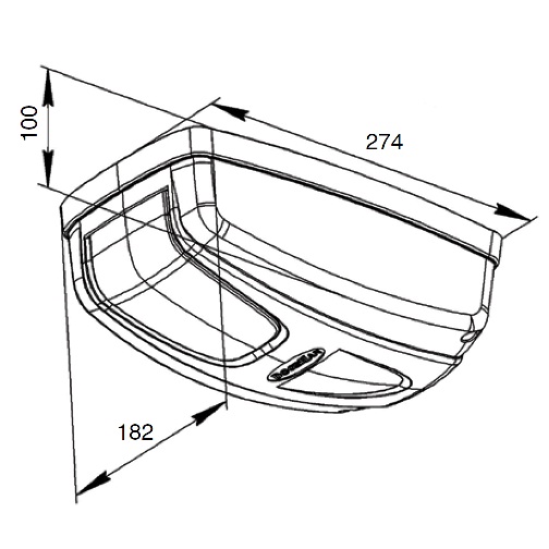
5 112 310 170 1. Housing cover 2. Display (for Se-500/500PRO models) 3. Control board 4. Motor reducer 5. Lamp/LED lamp for Se-500PRO/DIY-500 model 6. Lamp housing 7. Housing 8. Splined bushing 9. Reference point microswitch 3. OPERATOR UNIT 1 2 3 4 5 6 7 8 9 Sectional-500 182 274 100 WARNING! RISK OF INJURY! Have a qualified technician lay the cables 230 V AC. The cables must be laid in protective corrugated tubes. In case of supply cable damage, use the suitable type of the cable. Cables needed for installation of sect
-
8 OPERATOR CONTROL KEYS + — P S Operator programming Control block wiring diagram WARNING! The cable wires must be protected from contact with any rough or sharp parts. All connections shall be made only when power is off. Parameters Characteristics Power supply 180-240 V/50 Hz Power supply of accessories 24 V DC Maximal current of accessories 200 mA Working temperature range –20…+55 °C Radio control frequency 433 MHz
-
3 1.1. SPECIFICATIONS Parameter Units Power supply 220–240 V Consumed power 150 W Waiting mode 6 W Force 500 H Control Stepped (pulse) mode Motor 24 V DC Light 25 W Opening speed 7.8 m/min Door area 8 m 2 Operating temperatures range –20…+55 °C Fuses Power supply — 2.5 A; light — 2.5 A Radio control 433 MHz Transmission Chain Protection rating IP 20 Electric operator Operating manual Guide Curved arm U-shaped bracket Guide fastening bracket Headroom bracket Straight arm fastening bracket Slotted bu
Questions, Opinions and Exploitation Impressions:
You can ask a question, express your opinion or share our experience of DoorHan Sectional-500 device using right now.
Получай последние новости нашего магазина
Получай последние новости нашего магазина
Я согласен на обработку персональных данных
Контакты
г. Санкт-Петербург, ул. Химиков, д.18 Лит.А, оф. 36А
8(812)409-9297 Пн—Птн 9:00—18:00 (SPb)
zakaz@domokeys.net
Разделы
- Радиоуправление (брелки, приемники)
- Неро Электроникс
- Автоматика для ворот
- Запчасти для роллет и рольворот
- Запчасти для секционных ворот
- Комплектующие для откатных ворот
- Запчасти и комплектующие автоматики
- Домофоны и контроль доступа
- Автоматика и аксессуары для роллет
- Аксессуары шлагбаумов
Соцсети
Мы получаем и обрабатываем персональные данные посетителей нашего сайта в соответствии с официальной политикой. Если вы не даете согласия на обработку своих персональных данных,вам необходимо покинуть наш сайт.
Оплата


Главная страница » Ворота секционные » Автоматика DOORHAN » Комплект привода DOORHAN SE-500KIT для секционных ворот

для увеличения
кликните по изображению
заказ 2-3 дня
Этот товар сейчас просматривают 11 человек
товар № 727
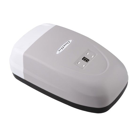
SE-500KIT комплект привода со встроенным блоком управления для секционных ворот высотой до 2,6 метра
Товар снят с производства. Аналог DOORHAN SE-800PROKIT.
Корпус привода выполнен в современном стильном дизайне. Привод легко соединяется с направляющей и закрепляется на потолке. Кроме того, корпус имеет встроенную лампу для освещения гаража, которая включается автоматически при открытии ворот.
Особенности:
- Предназначен для гаражных секционных ворот;
- Монтируется к потолку;
- Открывает ворота посредством цепной передачи;
- Устанавливается на ворота высотой до 2600 мм и площадью до 8 кв.м.
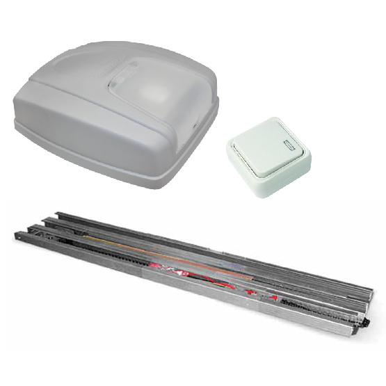
Состав комплекта:
- Привод SECTIONAL-500 со встроенным приемником
- FK-3300 Направляющая с цепью L=3300 (DOORHAN)
- Встроенный приемник 433 МГц (Doorhan)
Технические характеристики:
- Напряжение — 220 В
- Мощность — 100 Вт
- Усилие — 500 Н
- Площадь ворот — 8 м²
- Скорость каретки — 12 м/мин
- Высота ворот — 2600 мм
Сопутствующие товары
Автоматика
Радиоуправление
Аксессуары
Комплектующие
Запасные части