инструкцияGardena Smart Sileno City 500

gardena.com
Operator‘s manual
SILENO city, smart SILENO city
SILENO life, smart SILENO life
InDesign P01 omslag P01_P02_a5.indd 1 2018-12-07 15:39:39
Посмотреть инструкция для Gardena Smart Sileno City 500 бесплатно. Руководство относится к категории роботизированные газонокосилки, 5 человек(а) дали ему среднюю оценку 7.3. Руководство доступно на следующих языках: английский. У вас есть вопрос о Gardena Smart Sileno City 500 или вам нужна помощь? Задайте свой вопрос здесь
- Contents
- Introduction
- Safety
- Installation
- Operation
- Maintenance
- Troubleshooting
- Transportation, storage and disposal
- Technical data
- Warranty
- EC Declaration of Conformity

Свойства
| Тип | Роботизированная газонокосилка |
| Максимальная площадь газона | 500 m² |
| Рекомендуемая площадь газона | — m² |
| Мульчирование | — |
| Таймер | Да |
| Удобное хранение | Да |
| Режущая система | Вращающиеся ножи |
| Минимальная высота резки | 20 mm |
| Максимальная высота резки | 50 mm |
| Ширина реза | 160 mm |
| Регулируемый зазор между ножами | Да |
| Цвет товара | Green, Grey |
| Травосборник | — |
| Объем сбора травы | — L |
| Количество лезвий | 3 |
| Уровень шума | 58 dB |
| Тип дисплея | ЖК |
| Встроенный экран | Да |
Вес и размеры
| Ширина | 380 mm |
| Глубина | 550 mm |
| Высота | 230 mm |
| Вес | 7200 g |
Энергопитание
| Источник питания | Аккумулятор |
| Тип батареек | Встроенный |
| Технология батареи | Литий-ионная (Li-Ion) |
| Время зарядки | 1 h |
| Время работы батареи (мин) | 65 min |
| Потребляемая мощность в месяц (макс) | 4 кВт·ч |
| Мощность | — W |
Прочие свойства
Содержимое упаковки
показать больше
Не можете найти ответ на свой вопрос в руководстве? Вы можете найти ответ на свой вопрос ниже, в разделе часто задаваемых вопросов о Gardena Smart Sileno City 500.
Какой вес Gardena Smart Sileno City 500?
Какая высота Gardena Smart Sileno City 500?
Какая ширина Gardena Smart Sileno City 500?
Какая толщина Gardena Smart Sileno City 500?
Инструкция Gardena Smart Sileno City 500 доступно в русский?
Не нашли свой вопрос? Задайте свой вопрос здесь

Operator‘s manual
SILENO city, smart SILENO city
SILENO life, smart SILENO life
gardena.com
|
InDesign P01 omslag P01_P02_a5.indd 1 |
2018-12-07 15:39:39 |
||

Contents
|
1 Introduction |
||
|
1.1 |
Introduction…………………………………………. |
3 |
|
1.2 |
Product overview…………………………………. |
4 |
|
1.3 |
Symbols on the product………………………… |
5 |
|
1.4 |
Symbols on the display………………………… |
6 |
|
1.5 |
Symbols on the battery…………………………. |
6 |
|
1.6 |
Menu structure overview………………………. |
7 |
|
1.7 |
Menu structure overview………………………. |
8 |
|
1.8 |
Display……………………………………………….. |
9 |
|
1.9 |
Keypad ……………………………………………… |
9 |
|
2 Safety |
||
|
2.1 |
Safety definitions……………………………….. |
10 |
|
2.2 |
General safety instructions………………….. |
10 |
|
2.3 |
Safety instructions for operation…………… |
12 |
|
3 Installation |
||
|
3.1 |
Introduction — Installation…………………….. |
15 |
|
3.2 |
Before the installation of the wires……….. |
15 |
|
3.3 |
Before the installation of the product…….. |
15 |
|
3.4 |
Installation of the product……………………. |
19 |
|
3.5 |
To put the wire into position with stakes… |
20 |
|
3.6 |
To bury the boundary wire or the |
|
|
guide wire………………………………………………. |
21 |
|
|
3.7 |
To change the position of the |
|
|
boundary wire or the guide wire………………… |
21 |
|
|
3.8 |
To extend the boundary wire or the |
|
|
guide wire………………………………………………. |
21 |
|
|
3.9 |
After the installation of the product……….. |
21 |
|
3.10 To do the product settings…………………. |
22 |
|
|
4 Operation |
||
|
4.1 |
The ON/OFF button……………………………. |
29 |
|
4.2 |
To start the product……………………………. |
29 |
|
4.3 |
Operating modes……………………………….. |
29 |
|
4.4 |
Stop…………………………………………………. |
30 |
|
4.5 |
Switch off………………………………………….. |
30 |
|
4.6 |
Schedule and Standby……………………….. |
30 |
|
4.7 |
To charge the battery…………………………. |
31 |
|
4.8 |
Adjust the cutting height……………………… |
32 |
|
5 Maintenance |
||
|
5.1 |
Introduction — maintenance………………….. |
33 |
|
5.2 |
Clean the product………………………………. |
33 |
|
5.3 |
Replace the blades…………………………….. |
34 |
|
5.4 |
Software update………………………………… |
34 |
|
5.5 |
Battery……………………………………………… |
35 |
|
5.6 |
Winter service……………………………………. |
36 |
|
6 Troubleshooting |
||
|
6.1 |
Introduction — troubleshooting………………. |
37 |
|
6.2 |
Fault messages…………………………………. |
38 |
|
6.3 |
Information messages………………………… |
42 |
|
6.4 |
Indicator lamp in the charging station……. |
43 |
|
6.5 Symptoms………………………………………… |
44 |
|
|
6.6 |
Find breaks in the loop wire………………… |
45 |
|
7 Transportation, storage and disposal |
||
|
7.1 |
Transportation…………………………………… |
48 |
|
7.2 |
Storage…………………………………………….. |
48 |
|
7.3 |
Disposal……………………………………………. |
48 |
|
8 |
Technical data |
|
|
8.1 Technical data…………………………………… |
49 |
|
|
9 |
Warranty |
|
|
9.1 Guarantee terms……………………………….. |
52 |
|
|
10 EC Declaration of Conformity |
||
|
10.1 EC Declaration of Conformity…………….. |
53 |

1 Introduction
1.1 Introduction
Serial number:
PIN code:
Product registration key:
The serial number is on the product rating plate and on the product carton.
•Use the serial number to register your product on www.gardena.com.
1.1.1 Support
For support about the GARDENA product, speak to your GARDENA central service.
1.1.2 Product description
Note: GARDENA regularly updates the appearance and function of the products. Refer to Support on page 3.
The product is a robotic lawn mower. The product has a battery power source and cuts the grass
automatically. Collection of grass is not necessary.
The operator selects the operation settings with the keys on the keypad. The display shows the selected and possible operation settings, and the operation mode of the product.
The boundary wire and the guide wire controls the movement of the product within the work area.
|
953 — 002 — 12.12.2018 |
Introduction — 3 |
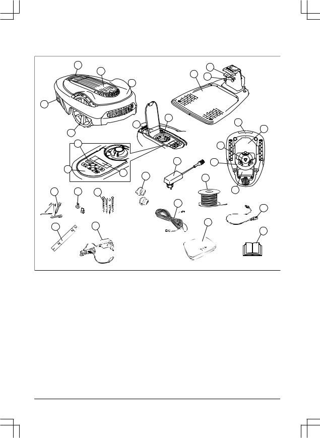
1.2 Product overview
|
3 |
7 |
||||
|
2 |
6 |
||||
|
8 |
|||||
|
1 |
|||||
|
4 |
|||||
|
9 |
|||||
|
10 |
16 |
||||
|
5 |
17 |
||||
|
13 |
15 |
||||
|
19 |
14 |
||||
|
12 |
11 |
||||
|
21 |
|||||
|
20 |
|||||
|
22 |
23 |
24 |
18 |
||
|
27 |
|||||
|
29 |
|||||
|
26 |
28 |
||||
|
25 |
|||||
|
30 |
The numbers in the figure represent:
1.Body
2.Hatch to display and keypad
3.Stop button
4.Rear wheel (SILENO city) / Rear wheels (SILENO life)
5.Front wheels
6.Charging station
7.Contact strips
8.LED for operation check of the charging station, boundary wire and guide wire
9.Cutting height adjustment
10.Rating plate
11.Display
12.Keypad
13.ON/OFF button
14.Cutting system
15.Blade disc
16.Handle
17.Chassis box with electronics, battery and motors
18.Battery cover
19.Power supply (the appearance of the power supply may differ depending on market)
20.Loop wire for boundary loop and guide wire
21.Couplers for loop wire
22.Stakes
23.Connector for the loop wire
24.Screws for securing the charging station
|
4 — Introduction |
953 — 002 — 12.12.2018 |
25.Measurement gauge for help when installing the boundary wire (the measurement gauge is broken loose from the box)
26.smart gateway power supply (only for smart model)
27.Low voltage cable
28.smart gateway (only for smart model)
29.smart gateway LAN-cable (only for smart model)
30.Operator’s Manual and Quick Guide
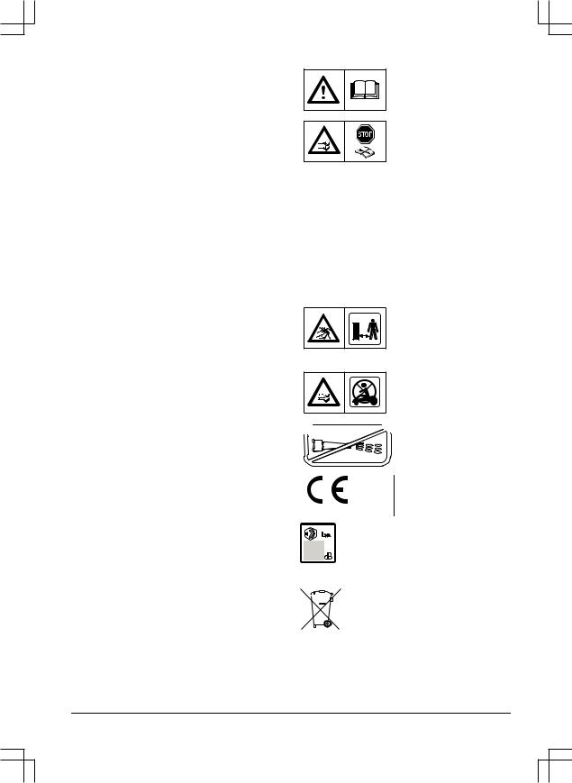
1.3 Symbols on the product
These symbols can be found on the product. Study them carefully.
WARNING: Read the user instructions before operating the product.
WARNING: Operate the disabling device before working on or lifting the
product.
The product can only start if the ON/OFF button is pressed and the indicator lamp is lit. Also, the correct PIN code must be entered. Before any inspections or maintenance is done, turn off the product and check that the indicator lamp on the ON/OFF button is not lit.
WARNING: Keep a safe distance from the product when operating. Keep
your hands and feet away from the rotating blades.
WARNING: Do not ride on the product. Never put your hands or feet close to or under the product.

 Do not use a high-pres-


 sure washer.
This product conforms to the applicable EC Directives.
Noise emission to surroundings. The product’s emissions are set out in
Technical data on page 49 and on the rating plate.
 It is not permitted to dispose this product as normal household waste. Ensure that the product is recycled in accordance with local legal
  requirements.
|
953 — 002 — 12.12.2018 |
Introduction — 5 |
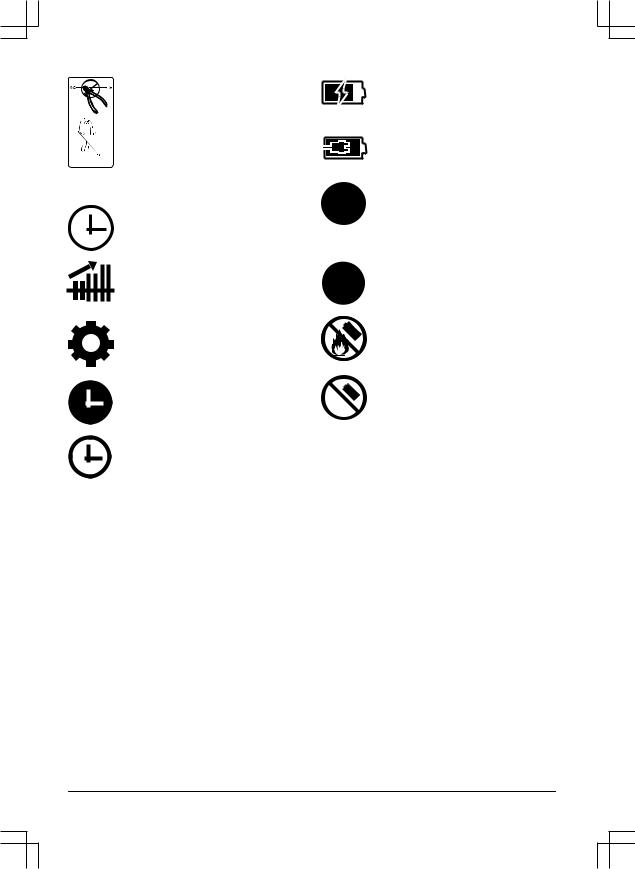
|
The low voltage cable must not be |
|
shortened, extended or spliced. |
 Do not use a trimmer nearby the low

 voltage cable. Be careful when

 trimming edges where the cables are


 placed.
1.4 Symbols on the display
The schedule function controls when the product cuts the lawn.
The SensorControl function automatically adapts the cutting intervals to the grass growth.
The settings function is where the general settings for the products are set.
The product will not cut the grass due to the schedule function.
 The product overrides the schedule function.
The battery indicator shows the charge level of the battery. When the product charges the symbol flashes.
The product is put in the charging station but do not charge the battery.
 The product is set in ECO-mode.
1.5 Symbols on the battery
 Read the user instructions.
Do not discard the battery into fire and do not expose the battery to a heat source.
 Do not immerse the battery into water.
|
6 — Introduction |
953 — 002 — 12.12.2018 |
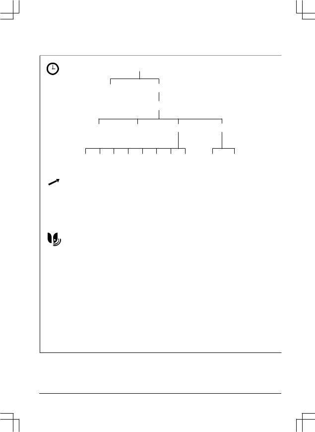
1.6 Menu structure overview
Schedule
Wizard Advanced
Overview week
|
Period 1 |
Period 2 |
Copy |
Reset |
|
All |
Mo |
Tu |
We |
Th |
Fr Sa |
Su |
Current All week |
||||||||||||
|
days |
day |
||||||||||||||||||
|
SensorControl** |
|||||||||||||||||||
|
Use |
Cutting time |
||||||||||||||||||
|
SensorControl |
|||||||||||||||||||
|
Low/Mid/High |
|||||||||||||||||||
|
smart system* |
|||||||||||||||||||
|
Exclude |
Status |
||||||||||||||||||
|
device |
|||||||||||||||||||
|
Connected |
|||||||||||||||||||
|
Yes/No |
|||||||||||||||||||
|
Signal |
|||||||||||||||||||
|
strength |
|||||||||||||||||||
|
Good |
Poor |
Bad |
* smart SILENO city and smart SILENO life ** SILENO life and smart SILENO life
|
953 — 002 — 12.12.2018 |
Introduction — 7 |

1.7 Menu structure overview
Settings
|
Security |
Lawn coverage |
Installation |
General |
Area 1-3
|
Security level |
Advanced |
||||||
|
New loop |
Change |
||||||
|
signal |
PIN code |
||||||
Low Medium* High
|
Starting |
Drive past |
ECO |
Mower |
|
point |
wire |
mode |
house |
|
Time & |
Language |
Country |
Reset all |
About |
|
date |
user setting |
|
How? How |
How |
Disable |
More Set time |
Set date |
Time format |
Date format |
||
|
far? |
often? |
|||||||
|
Test |
Reset |
* SILENO life, smart SILENO life
|
8 — Introduction |
953 — 002 — 12.12.2018 |
1.8 Display
The display on the product shows information and settings of the product.
To access the display, push the STOP button.
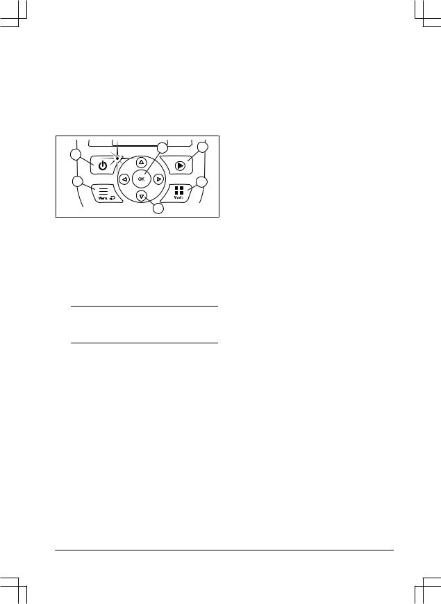
1.9 Keypad
The keypad consists of 6 groups of buttons:
1.The ON/OFF button is used to turn the product ON/OFF. The indicator lamp on the ON/OFF button is an important status indicator. Refer to The indicator lamp on page 29.
2.The Start button is used to start the operation of the product.
3.The Menu button is used to go to the main menu.
Note: The Menu button is also used as a Back button, that is, when moving back up in the menu lists.
4.The Mode button is used to choose operating mode, for example, Main area or
Park.
5.The OK button is used to confirm the chosen settings in the menus.
6.The arrow keys are used to navigate in the menu. The up/down arrow keys are also used to enter digits, for example, PIN code, time and date
|
953 — 002 — 12.12.2018 |
Introduction — 9 |
2 Safety
2.1 Safety definitions
Warnings, cautions and notes are used to point out specially important parts of the manual.
WARNING: Used if there is a risk of injury or death for the operator or bystanders if the instructions in the manual are not obeyed.
CAUTION: Used if there is a risk of damage to the product, other materials or the adjacent area if the instructions in the manual are not obeyed.
Note: Used to give more information that is necessary in a given situation.
2.2 General safety instructions
The following system is used in the Operator’s Manual to make it easier to use:
•Text written in italics is a text that is shown on the display of the product or is a reference to another section in the Operator’s Manual.
•Text written in bold is one of the buttons on the keypad of the product.
•Text written in UPPERCASE and italics refer to the different operating modes available in the product.
|
10 — Safety |
953 — 002 — 12.12.2018 |
![]()
2.2.1 IMPORTANT. READ CAREFULLY BEFORE USE. KEEP FOR FUTURE REFERENCE
The operator is responsible for accidents or hazards occurring to other people or property.
This appliance is not intended for use by persons (including children) with reduced physical, sensory or mental capabilities (that could affect a safe handling of the product), or lack of experience and knowledge, unless they have been given supervision or instruction concerning use of the appliance by a person responsible for their safety.
This appliance can be used by children aged from 8 years and above and persons with reduced physical, sensory or mental capabilities or lack of experience and knowledge if they have been given supervision or instruction concerning use of the appliance in a safe way and understand the hazards involved. Local regulations may restrict the age of the operator. Cleaning and maintenance shall not be made by children without supervision.
Never connect the power supply to an outlet if the plug or cord is damaged. Worn or damaged cord increase the risk of electric shock.
Only charge the battery in the included charging station. Incorrect use may result in electric shock, overheating or leaking of corrosive liquid from the battery. In the event of leakage of electrolyte, flush with water/neutralizing agent. Seek medical help if it comes in contact with the eyes.
Use only original batteries recommended by the manufacturer. Product safety cannot be guaranteed with other than original batteries. Do not use non-rechargeable batteries.
The appliance must be disconnected from the supply mains when removing the battery.
|
953 — 002 — 12.12.2018 |
Safety — 11 |
WARNING: The product can be dangerous if used incorrectly.
WARNING: Do not use the product when persons, especially children, or animals, are in the work area.
WARNING: Keep your hands and feet away from the rotating blades. Never put your hands or feet close to or under the product when the motor is running.
2.3 Safety instructions for operation
2.3.1 Use
•The product is designed to mow grass in open and level ground areas. It may only be used with the equipment recommended by the manufacturer. All other types of use are incorrect. The manufacturer’s instructions with regard to operation/maintenance must be followed precisely.
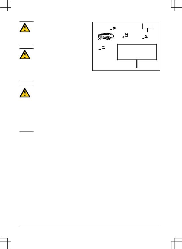
•Warning signs shall be placed around the work area of the product if it is used in public areas. The signs shall have the following text: Warning! Automatic lawnmower!
Keep away from the machine! Supervise children!
•Use the operating mode Park or turn off the product when persons, especially children, or animals, are in the work area. It is recommended to program the product for use during hours when the area is free from activity, e.g. at night. Refer to To set the schedule on page 23. Consider that certain species, e.g. hedgehogs, are active at night. They can potentially be harmed by the product.
•The product may only be operated, maintained and repaired by persons that are fully conversant with its special characteristics and safety regulations. Please read the Operator’s Manual carefully and make sure you understand the instructions before using the product.
•It is not permitted to modify the original design of the product. All modifications are made at your own risk.
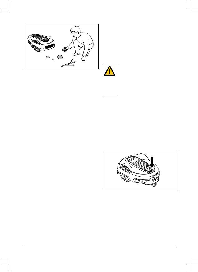
•Check that there are no stones, branches, tools, toys or other objects on the lawn that can damage the blades. Objects on the lawn can also lead to the product getting stuck.
Help may be required to remove the object before the product can continue mowing. Always turn off the product using the ON/OFF button before clearing a blockage.
|
12 — Safety |
953 — 002 — 12.12.2018 |
•Start the product according to the instructions. When the product is turned on, make sure to keep your hands and feet away from the rotating blades. Never put your hands and feet under the product.
•Never touch moving hazardous parts, such as the blade disc, before it has come to a complete stop.
•Never lift up the product or carry it around when it is turned on.
•Do not let persons who do not know how the product works and behaves use it.
•The product must never be allowed to collide with persons or other living creatures. If a person or other living creature comes in the product’s way it shall be stopped immediately. Refer to Stop on page 30.
•Do not put anything on top of the product or its charging station.
•Do not allow the product to be used with a defective guard, blade disc or body. Neither should it be used with defective blades, screws, nuts or cables. Never connect a damaged cable, or touch a damaged cable before it is disconnected from the supply.
•Do not use the product if the ON/OFF button does not work.
•Always switch off the product using the ON/OFF button when the product is not in use. The product can only start when the ON/OFF button has been turned on and the correct PIN code has been entered.
•GARDENA does not guarantee full compatibility between the product and other types of wireless systems such as remote controls, radio transmitters, hearing loops, underground electric animal fencing or similar.
•Metal objects in the ground (for example reinforced concrete or anti-mole nets) can
result in a stoppage. The metal objects can cause interference with the loop signal which then can lead to a stoppage.
•Operation and storage temperature is 0-50 °C / 32-122 °F. Temperature range for charging is 0-45 °C / 32-113 °F. Too high temperatures might cause damage to the product.
2.3.2Battery safety
WARNING: Lithium-ion batteries can explode or cause fire if disassembled, short-circuited, exposed to water, fire, or high temperatures. Handle carefully, do not dismantle, open the battery or use any type of electrical/mechanical abuse. Avoid storage in direct sunlight.
For more information about the battery, refer to
Battery on page 35
2.3.3 How to lift and move the product
To safely move from or within the work area:
1.Press the STOP button to stop the product. If security is set to high level (refer to To set the security level on page 23) the PIN code has to be entered. The PIN code contains four digits and is selected when you start the product for the first time. Refer to To do the basic settings on page 21.
2.Press the ON/OFF button and make sure the product is turned off. Check that the indicator lamp on the ON/OFF button is not lit. This means that the product is disabled. Refer to The indicator lamp on page 29.
|
953 — 002 — 12.12.2018 |
Safety — 13 |
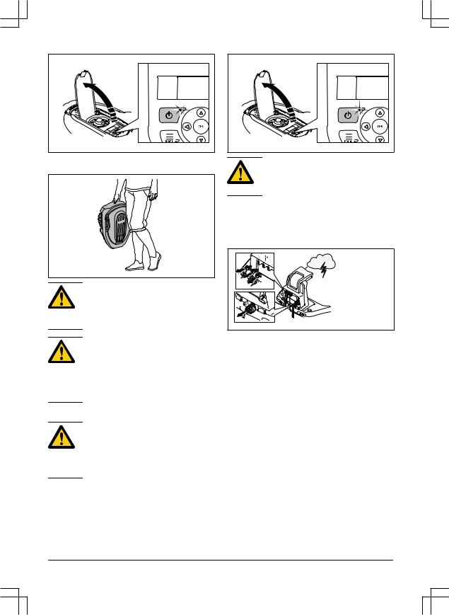
3.Carry the product by the handle with the blade disc away from the body.
WARNING: The product must be turned off before lifting it. The product is disabled when the indicator lamp on the ON/OFF button is not lit.
CAUTION: Never use a high-pressure washer to clean the product. Never use solvents for cleaning.
Inspect the product weekly and replace any damaged or worn parts. Refer to Introduction — maintenance on page 33.
2.3.5 In the event of a thunderstorm
CAUTION: Do not lift the product when it is parked in the charging station. It can damage the charging station and/or the product. Press STOP and pull the product out of the charging station before lifting it.
2.3.4 Maintenance
WARNING: The product must be turned off before any maintenance is done. The product is disabled when the indicator lamp on the ON/OFF button is not lit.
To reduce the risk of damage to electrical components in the product and the charging station, we recommend that all connections to the charging station are disconnected (power supply, boundary wire and guide wire) if there is a risk of a thunderstorm.
1.Mark the wires to simplify reconnecting. The charging station’s connections are marked R, L and GUIDE.
2.Disconnect all connected wires and the power supply.
3.Connect all the wires and the power supply if there is no longer a risk of thunder. It is important that each wire is connected to the right place.
|
14 — Safety |
953 — 002 — 12.12.2018 |
3 Installation
3.1 Introduction — Installation
WARNING: Read and understand the safety chapter before you install the product.
CAUTION: Only use original spare parts and installation material.
Note: Refer to www.gardena.com for more information about installation.
3.2 Before the installation of the wires
You can select to attach the wires with stakes or bury them. You can use the 2 procedures for the same work area.
•Bury the boundary wire or the guide wire if you are going to use a dethatcher on the work area. If not, attach the boundary wire or guide wire with stakes.
•Cut the grass before you install the product. Make sure that the grass is maximum 4 cm / 1.6 in.
Note: The first weeks after installation the perceived sound level when cutting the grass may be higher than expected. When the product has cut the grass for some time, the perceived sound level is much lower.
3.3 Before the installation of the product
•Make a blueprint of the work area and include all obstacles.
•Make a mark on the blueprint where to put the charging station, the boundary wire and the guide wire.
•Make a mark on the blueprint where the guide wire connects to the boundary wire. Refer to To install the guide wire on page 20.
•Fill in holes in the lawn.
Note: Holes with water in the lawn can cause damage to the product.
3.3.1 To examine where to put the charging station
•Keep a minimum 2 m / 6.6 ft. of free space in front of the charging station.
•Keep a minimum of 30 cm / 12 in. of free space to the right and left of the center of the charging station.
•Put the charging station near an outdoor power outlet.
•Put the charging station on a level surface.
|
953 — 002 — 12.12.2018 |
Installation — 15 |
MAX +/- 2 CM / 0.8 IN.
•Put the charging station in the lowest possible section of the work area.
•Put the charging station in an area with protection from the sun.
•If the charging station is installed on an island, make sure to connect the guide wire to the island. Refer to To make an island on page 17.
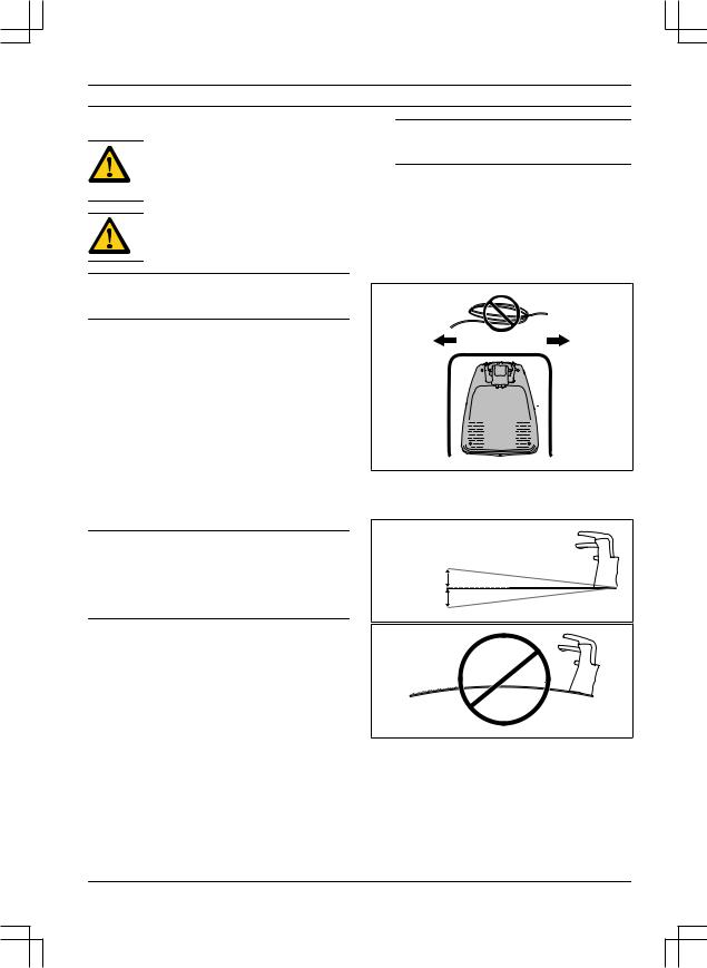
CAUTION: Do not put the low-voltage cable in a coil or below the charging station plate. The coil causes interference with the signal from the charging station.
3.3.3 To examine where to put the boundary wire
CAUTION: If the work area is adjacent to water bodies, slopes, precipices or a public road, the boundary wire must have a protective wall. The wall must be minimum 15 cm / 6 in. in height.
3.3.2 To examine where to put the power supply
•Put the power supply in an area with a roof and protection from the sun and rain.
•Put the power supply in an area with good airflow.
•Use a residual-current device (RCD) when you connect the power supply to the power outlet.
WARNING: Do not change the power supply. Do not cut or extend the lowvoltage cable. There is a risk of electrical shock.
Low-voltage cables of different lengths are available as accessories.
CAUTION: Make sure that the blades on the product do not cut the lowvoltage cable.
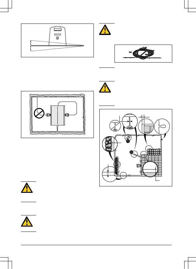
•Put the boundary wire around all of the work area (A). Adapt the distance between the boundary wire and obstacles.
•Put the boundary wire 35 cm / 14 in. (B) from an obstacle that is more than 5 cm / 2 in. high.
•Put the boundary wire 30 cm / 12 in. (C) from an obstacle that is 1-5 cm / 0.4-2 in. high.
•Put the boundary wire 10 cm / 4 in. (D) from an obstacle that is less than 1 cm / 0.4 in.
|
16 — Installation |
953 — 002 — 12.12.2018 |

•If you have a paving stone path that is in level with the lawn, put the boundary wire below the paving stone.
Note: If the paving stone is minimum 30 cm / 12 in. wide, use the factory setting for the Drive Past Wire function to cut all the grass adjacent to the paving stone.
CAUTION: Do not let the product operate on gravel.
•If you make an island, put the boundary wire that runs to and from the island near together (E). Put the wires in the same stake.
•Make an eyelet (F) where the guide wire is to be connected to the boundary wire.
CAUTION: Do not make sharp bends when you install the boundary wire.
CAUTION: For careful operation without noise, isolate all obstacles such as trees, roots and stones.
3.3.3.1 To put the boundary wire in a slope
•SILENO city and smart SILENO city: For slopes steeper than 25% inside the work area, isolate the slope with boundary wire.
•SILENO life and smart SILENO life: For slopes steeper than 30% inside the work area, isolate the slope with boundary wire.
•For slopes steeper than 10% along the outer edge of the lawn, put the boundary wire 20 cm / 8 in. (A) from the edge.
•For slopes adjacent to a public road, put a fence or a protective wall along the outer edge of the slope.
3.3.3.2 Passages
A passage is a section that has boundary wire on each side and that connects 2 work areas. The passage must be a minimum of 60 cm / 24 in. wide.
Note: If a passage is less than 2 m / 6.5 ft. wide, install a guide wire through the passage.
3.3.3.3 To make an island
•Put the boundary wire to and around the obstacle to make an island.
•Put the 2 sections of boundary wire that run to and from the obstacle together.
•Put the 2 sections of boundary wire in the same stake.
CAUTION: Do not put a section of boundary wire across the other. The sections of boundary wire must be parallel.
CAUTION: Do not put the guide wire across the boundary wire, for example a boundary wire that goes to an island.
|
953 — 002 — 12.12.2018 |
Installation — 17 |
 Loading…
Gardena


-
Артикул
15002-33.000.00 -
Гарантия
2 года -
Ширина скашивания, см
16 -
Мульчирование
да -
Самоходная
да -
Травосборник
нет -
Площадь, м²
500 -
Кол-во режимов регулировки высоты
бесступенчатая -
Регулировка высоты
центральная -
Габариты без упаковки, мм
550х380х230
Все характеристики
Товар участвует в акциях
Бесплатная предпродажная подготовка
Дополнительная скидка в корзине
Описание

Газонокосилка-робот Gardena SILENO city 500 подходит для автоматической работы на участке площадью до 500 м². Устройство отличается низким уровнем шума и малым потреблением энергии до 4 кВт в час.
Ключевые особенности:
- Уровень шума – 58 дБ.
- Автоматическое выполнение всей работы.
- Функция SensorControl.
- Ограничительный провод.
- Безопасное поднятие.
- Функция кошения с места.
- Использование при любой погоде.
- Датчик столкновения.
- Простое программирование.
- Интеллектуальным датчик температуры.
- Простое техническое обслуживание.
Комфортная эксплуатация Gardena SILENO city 500
С использованием газонокосилки-робота вам не придется выполнять работу самим. Машина равномерно подстригает растительность на участке, проходит через узкие места, самостоятельно выбирает маршрут и возвращается на зарядную станцию. Устройство обрабатывает газон даже в тупиках, а затем меняет направление для дальнейшей работы.
Функция SensorControl – это интеллектуальная система стрижки, которая контролирует продолжительность кошения с учетом скорости роста травы.
Зона работы определяется при помощи ограничительного провода.
При поднятии газонокосилки Gardena SILENO city 500 вверх работа ножей останавливается.
Функция кошения с места обеспечивает спиральную стрижку, что удобно при обработке труднодоступных мест, например, под садовой мебелью.
Продуманная конструкция
Газонокосильную машину можно использовать в любую погоду. Она не сломается под воздействием солнца или дождя.
Встроенный датчик столкновения позволят продолжить работу в другом направлении, если машина столкнется с препятствием.
Для простого программирования предусмотрен дисплей и удобное меню. Благодаря этому вы самостоятельно можете задавать продолжительность стрижки и размер вашего участка. Система автоматически составит план работы.
Устройство оснащено интеллектуальным датчиком, который определяет температуру окружения. При опасности замерзания программа приостанавливает работу машины.
Конструкция легко разбирается для проведения технического обслуживания. Вы можете очищать корпус, колеса и ножи с помощью полива из садового шланга.
Производитель
Когда речь заходит об уходе за садом, миллионы домовладельцев и садоводов по всему миру отдают предпочтение инструментам GARDENA, поставляемым из г. Ульм, Германия. В ассортименте GARDENA есть все необходимое для работы в саду – будь то системы полива, насосы, садовые инструменты или инструменты по уходу за газоном, деревьями и кустарниками, прудами или почвой. Сегодня GARDENA — это признанный лидер среди европейских производителей садовых инструментов высокого качества. GARDENA представлена более чем в 120 странах по всему миру. Добиться доверия тех, кто считает свой сад «райским уголком» и местом для отдыха, достойным всего самого лучшего, не так-то просто. Но нам это удается!
Германия — родина бренда
Китай — страна производства
Подробнее о бренде
Подробнее
Нашли ошибку в описании или в характеристиках?
Выделите текст и нажмите Ctrl+Enter
Характеристики
Смотреть все
Все
- Общие
-
Ширина скашивания
16 -
Мульчирование
да -
Самоходная
да -
Травосборник
нет -
Площадь
500 -
Кол-во режимов регулировки высоты
бесступенчатая -
Регулировка высоты
центральная -
Панель управления
ЖК-дисплей -
Max склон
25% -
Программирование круглосуточной работы
нет -
Высота скашивания max
50 -
Число передач
1 -
Высота скашивания min
20 -
Уровень шума, дБ(А)
58 - Двигатель
-
Тип двигателя
аккумуляторный - Прочее
-
Серия
SILENO city - Габариты и вес
-
Габариты без упаковки
550х380х230 -
Вес нетто, кг
7.3 -
Вес упакованного товара, кг
14,82 -
Единица товара
Штука
Комплектация
- Газонокосилка-робот Gardena SILENO city 500
- Упаковка
Характеристики
Общие
-
Ширина скашивания
16 -
Мульчирование
да -
Самоходная
да -
Травосборник
нет -
Площадь
500 -
Кол-во режимов регулировки высоты
бесступенчатая -
Регулировка высоты
центральная -
Панель управления
ЖК-дисплей -
Max склон
25% -
Программирование круглосуточной работы
нет -
Высота скашивания max
50 -
Число передач
1 -
Высота скашивания min
20 -
Уровень шума, дБ(А)
58
Двигатель
-
Тип двигателя
аккумуляторный
Прочее
-
Бренд
Gardena -
Модель
SILENO city 500 -
Гарантия
2 года -
Серия
SILENO city
Габариты и вес
-
Габариты без упаковки
550х380х230 -
Вес нетто, кг
7.3 -
Вес упакованного товара, кг
14,82 -
Единица товара
Штука -
Габариты упакованного товара, мм
490 x 590 x 335
Файлы
Инструкция для Газонокосилки-робота Gardena SILENO city 500.pdf
8.44 МБ
Скачать
Отзывы
У этого товара еще нет ни одного отзыва и вопроса — ваш может стать первым!
У этого товара еще нет ни одного отзыва — ваш может стать первым!
Об этом товаре еще не задавали вопросы — ваш может стать первым!
Сопутствующие товары
Код: 72473

Секатор механический Вихрь 200 мм
Товар снят с производства: Нет
Вес упакованного товара, кг: 0.2
Габариты упакованного товара, мм: 200 x 50 x 18
Код: 72472

Секатор механический Вихрь 200 мм
Товар снят с производства: Нет
Вес упакованного товара, кг: 0.2
Габариты упакованного товара, мм: 200 x 50 x 18
Код: 72474

Секатор механический Вихрь 200 мм
Товар снят с производства: Нет
Вес упакованного товара, кг: 0.2
Габариты упакованного товара, мм: 200 x 50 x 18
Код: 74197

Электрический триммер HUTER GET-400
Тип двигателя: электрический
Мощность (кВт): 0.35
Толщина лески, мм: 1.2
Ширина скашивания для лески, мм: 240
Напряжение, В: 220
Вес нетто, кг: 1.7
Гарантия: 1 год
Товар снят с производства: Нет
Площадь обработки, м²: 500
Обороты двигателя, об/мин: 10000
Код: 74196

Электрический триммер HUTER GET-24
Тип двигателя: электрический
Мощность (кВт): 0.35
Толщина лески, мм: 1.2
Ширина скашивания для лески, мм: 240
Напряжение, В: 220
Вес нетто, кг: 1.68
Гарантия: 1 год
Товар снят с производства: Нет
Площадь обработки, м²: 250
Обороты двигателя, об/мин: 10000
Код: 111099

Аккумуляторный кусторез HUTER GET-120 (1 x 1.5 Ач, ЗУ)
Тип: аккумуляторный
Вес нетто, кг: 1
Гарантия: 1 год
Товар снят с производства: Нет
Габариты без упаковки, мм: 540х150х150
Габариты без упаковки, см: 54х15х15
Серия: GET
Вес упакованного товара, кг: 2
Габариты упакованного товара, мм: 650х180х180
Код: 110173

Электрический триммер Bosch EasyGrassCut 23
Тип двигателя: электрический
Мощность (кВт): 0.28
Толщина лески, мм: 1.6
Ширина скашивания для лески, мм: 230
Напряжение, В: 220
Вес нетто, кг: 1.9
Гарантия: 2 года
Товар снят с производства: Нет
Площадь обработки, м²: 400
Обороты двигателя, об/мин: 12500
Код: 72478

Секатор механический Gardena B/M
Гарантия: 25 лет
Товар снят с производства: Нет
Вес упакованного товара, кг: 0.26
Габариты упакованного товара, мм: 266 x 112 x 22
Код: 93413

Аккумуляторный триммер ZITREK GreenCut 20 (2 x 1.5 Ач, ЗУ)
Тип двигателя: аккумуляторный
Ширина скашивания для ножа, мм: 150
Вес нетто, кг: 1.8
Гарантия: 1 год
Товар снят с производства: Нет
Габариты без упаковки, мм: 912 x 150 x 160
Габариты без упаковки, см: 91,2 x 15 x 16
Серия: GreenCut
Вес упакованного товара, кг: 1.8
Габариты упакованного товара, мм: 88 x 160 x 912
View a manual of the Gardena Smart Sileno City 500 below. All manuals on ManualsCat.com can be viewed completely free of charge. By using the ‘Select a language’ button, you can choose the language of the manual you want to view.
Page: 1
gardena.com
Operator‘s manual
SILENO city, smart SILENO city
SILENO life, smart SILENO life
InDesign P01 omslag P01_P02_a5.indd 1 2018-12-07 15:39:39
Page: 2
Contents
1 Introduction
1.1 Introduction………………………………………….3
1.2 Product overview………………………………….4
1.3 Symbols on the product…………………………5
1.4 Symbols on the display………………………… 6
1.5 Symbols on the battery………………………….6
1.6 Menu structure overview………………………. 7
1.7 Menu structure overview………………………. 8
1.8 Display………………………………………………..9
1.9 Keypad ……………………………………………… 9
2 Safety
2.1 Safety definitions………………………………..10
2.2 General safety instructions…………………..10
2.3 Safety instructions for operation……………12
3 Installation
3.1 Introduction — Installation…………………….. 15
3.2 Before the installation of the wires……….. 15
3.3 Before the installation of the product……..15
3.4 Installation of the product……………………. 19
3.5 To put the wire into position with stakes…20
3.6 To bury the boundary wire or the
guide wire……………………………………………….21
3.7 To change the position of the
boundary wire or the guide wire………………… 21
3.8 To extend the boundary wire or the
guide wire……………………………………………….21
3.9 After the installation of the product………..21
3.10 To do the product settings………………….22
4 Operation
4.1 The ON/OFF button…………………………….29
4.2 To start the product……………………………. 29
4.3 Operating modes………………………………..29
4.4 Stop………………………………………………….30
4.5 Switch off…………………………………………..30
4.6 Schedule and Standby……………………….. 30
4.7 To charge the battery…………………………. 31
4.8 Adjust the cutting height………………………32
5 Maintenance
5.1 Introduction — maintenance…………………..33
5.2 Clean the product……………………………….33
5.3 Replace the blades……………………………..34
5.4 Software update………………………………… 34
5.5 Battery………………………………………………35
5.6 Winter service…………………………………….36
6 Troubleshooting
6.1 Introduction — troubleshooting……………….37
6.2 Fault messages………………………………….38
6.3 Information messages…………………………42
6.4 Indicator lamp in the charging station…….43
6.5 Symptoms………………………………………… 44
6.6 Find breaks in the loop wire………………… 45
7 Transportation, storage and disposal
7.1 Transportation…………………………………… 48
7.2 Storage……………………………………………..48
7.3 Disposal…………………………………………….48
8 Technical data
8.1 Technical data……………………………………49
9 Warranty
9.1 Guarantee terms……………………………….. 52
10 EC Declaration of Conformity
10.1 EC Declaration of Conformity……………..53
2 953 — 002 — 12.12.2018
Page: 3
1 Introduction
1.1 Introduction
Serial number:
PIN code:
Product registration key:
The serial number is on the product rating plate and on the product carton.
• Use the serial number to register your product on www.gardena.com.
1.1.1 Support
For support about the GARDENA product, speak
to your GARDENA central service.
1.1.2 Product description
Note: GARDENA regularly updates the
appearance and function of the products. Refer
to Support on page 3.
The product is a robotic lawn mower. The product
has a battery power source and cuts the grass
automatically. Collection of grass is not
necessary.
The operator selects the operation settings with
the keys on the keypad. The display shows the
selected and possible operation settings, and the
operation mode of the product.
The boundary wire and the guide wire controls
the movement of the product within the work
area.
953 — 002 — 12.12.2018 Introduction — 3
Page: 4
1.2 Product overview
1
5
4
3
9
28
21
27
10
22 23
29
26
30
25
24
19
6 8
7
2
18
15
14
17
16
20
13
12
11
The numbers in the figure represent:
1. Body
2. Hatch to display and keypad
3. Stop button
4. Rear wheel (SILENO city) / Rear wheels
(SILENO life)
5. Front wheels
6. Charging station
7. Contact strips
8. LED for operation check of the charging
station, boundary wire and guide wire
9. Cutting height adjustment
10. Rating plate
11. Display
12. Keypad
13. ON/OFF button
14. Cutting system
15. Blade disc
16. Handle
17. Chassis box with electronics, battery and
motors
18. Battery cover
19. Power supply (the appearance of the power
supply may differ depending on market)
20. Loop wire for boundary loop and guide wire
21. Couplers for loop wire
22. Stakes
23. Connector for the loop wire
24. Screws for securing the charging station
4 — Introduction 953 — 002 — 12.12.2018
Page: 5
25. Measurement gauge for help when installing
the boundary wire (the measurement gauge
is broken loose from the box)
26. smart gateway power supply (only for smart
model)
27. Low voltage cable
28. smart gateway (only for smart model)
29. smart gateway LAN-cable (only for smart
model)
30. Operator’s Manual and Quick Guide
1.3 Symbols on the product
These symbols can be found on the product.
Study them carefully.
WARNING: Read the
user instructions before
operating the product.
WARNING: Operate the
disabling device before
working on or lifting the
product.
The product can only start
if the ON/OFF button is
pressed and the indicator
lamp is lit. Also, the cor-
rect PIN code must be
entered. Before any in-
spections or maintenance
is done, turn off the prod-
uct and check that the in-
dicator lamp on the
ON/OFF button is not lit.
WARNING: Keep a safe
distance from the product
when operating. Keep
your hands and feet away
from the rotating blades.
WARNING: Do not ride
on the product. Never put
your hands or feet close
to or under the product.
Do not use a high-pres-
sure washer.
This product conforms to
the applicable EC Direc-
tives.
Noise emission to surroundings. The
product’s emissions are set out in
Technical data on page 49 and on the
rating plate.
It is not permitted to dispose this
product as normal household waste.
Ensure that the product is recycled in
accordance with local legal
requirements.
953 — 002 — 12.12.2018 Introduction — 5
Page: 6
The low voltage cable must not be
shortened, extended or spliced.
Do not use a trimmer nearby the low
voltage cable. Be careful when
trimming edges where the cables are
placed.
1.4 Symbols on the display
The schedule function controls when
the product cuts the lawn.
The SensorControl function
automatically adapts the cutting
intervals to the grass growth.
The settings function is where the
general settings for the products are
set.
The product will not cut the grass due
to the schedule function.
The product overrides the schedule
function.
The battery indicator shows the charge
level of the battery. When the product
charges the symbol flashes.
The product is put in the charging
station but do not charge the battery.
The product is set in ECO-mode.
1.5 Symbols on the battery
Read the user instructions.
Do not discard the battery into fire and
do not expose the battery to a heat
source.
Do not immerse the battery into water.
6 — Introduction 953 — 002 — 12.12.2018
Page: 7
1.6 Menu structure overview
Schedule
Overview week
Period 1 Period 2 Copy
Su Current
day
All week
Sa
Fr
Th
We
Tu
Mo
All
days
Reset
* smart SILENO city and smart SILENO life
** SILENO life and smart SILENO life
Wizard Advanced
smart system*
Good Poor Bad
Connected
Yes/No
Signal
strength
Status
Exclude
device
SensorControl**
Low/Mid/High
Cutting time
Use
SensorControl
953 — 002 — 12.12.2018 Introduction — 7
Page: 8
1.7 Menu structure overview
Settings
Time &
date
Set time Set date Time format Date format
Language Country Reset all
user setting
About
Security Lawn coverage Installation General
Low Medium*
Change
PIN code
New loop
signal
Security level Advanced
Area 1-3
How? How
often?
How
far?
Disable
Reset
Test
More
Starting
point
Drive past
wire
ECO
mode
Mower
house
High
* SILENO life, smart SILENO life
8 — Introduction 953 — 002 — 12.12.2018
Page: 9
1.8 Display
The display on the product shows information
and settings of the product.
To access the display, push the STOP button.
1.9 Keypad
The keypad consists of 6 groups of buttons:
1
2
4
3
5
6
1. The ON/OFF button is used to turn the
product ON/OFF. The indicator lamp on the
ON/OFF button is an important status
indicator. Refer to The indicator lamp on
page 29.
2. The Start button is used to start the
operation of the product.
3. The Menu button is used to go to the main
menu.
Note: The Menu button is also used as a
Back button, that is, when moving back up
in the menu lists.
4. The Mode button is used to choose
operating mode, for example, Main area or
Park.
5. The OK button is used to confirm the
chosen settings in the menus.
6. The arrow keys are used to navigate in the
menu. The up/down arrow keys are also
used to enter digits, for example, PIN code,
time and date
953 — 002 — 12.12.2018 Introduction — 9
Page: 10
2 Safety
2.1 Safety definitions
Warnings, cautions and notes are used to point
out specially important parts of the manual.
WARNING: Used if there is a risk of
injury or death for the operator or
bystanders if the instructions in the
manual are not obeyed.
CAUTION: Used if there is a risk of
damage to the product, other materials
or the adjacent area if the instructions
in the manual are not obeyed.
Note: Used to give more information that is
necessary in a given situation.
2.2 General safety instructions
The following system is used in the Operator’s
Manual to make it easier to use:
• Text written in italics is a text that is shown
on the display of the product or is a
reference to another section in the
Operator’s Manual.
• Text written in bold is one of the buttons on
the keypad of the product.
• Text written in UPPERCASE and italics refer
to the different operating modes available in
the product.
10 — Safety 953 — 002 — 12.12.2018
Page: 11
2.2.1 IMPORTANT. READ CAREFULLY
BEFORE USE. KEEP FOR FUTURE
REFERENCE
The operator is responsible for accidents or hazards occurring to
other people or property.
This appliance is not intended for use by persons (including chil-
dren) with reduced physical, sensory or mental capabilities (that
could affect a safe handling of the product), or lack of experience
and knowledge, unless they have been given supervision or in-
struction concerning use of the appliance by a person responsible
for their safety.
This appliance can be used by children aged from 8 years and
above and persons with reduced physical, sensory or mental ca-
pabilities or lack of experience and knowledge if they have been
given supervision or instruction concerning use of the appliance in
a safe way and understand the hazards involved. Local regula-
tions may restrict the age of the operator. Cleaning and mainte-
nance shall not be made by children without supervision.
Never connect the power supply to an outlet if the plug or cord is
damaged. Worn or damaged cord increase the risk of electric
shock.
Only charge the battery in the included charging station. Incorrect
use may result in electric shock, overheating or leaking of corro-
sive liquid from the battery. In the event of leakage of electrolyte,
flush with water/neutralizing agent. Seek medical help if it comes
in contact with the eyes.
Use only original batteries recommended by the manufacturer.
Product safety cannot be guaranteed with other than original bat-
teries. Do not use non-rechargeable batteries.
The appliance must be disconnected from the supply mains when
removing the battery.
953 — 002 — 12.12.2018 Safety — 11
Page: 12
WARNING: The product
can be dangerous if used
incorrectly.
WARNING: Do not use
the product when
persons, especially
children, or animals, are
in the work area.
WARNING: Keep your
hands and feet away
from the rotating blades.
Never put your hands or
feet close to or under the
product when the motor
is running.
2.3 Safety instructions for operation
2.3.1 Use
• The product is designed to mow grass in
open and level ground areas. It may only be
used with the equipment recommended by
the manufacturer. All other types of use are
incorrect. The manufacturer’s instructions
with regard to operation/maintenance must
be followed precisely.
• Warning signs shall be placed around the
work area of the product if it is used in public
areas. The signs shall have the following
text: Warning! Automatic lawnmower!
Keep away from the machine! Supervise
children!
Warning!
Automatic lawnmower!
Keep away from the machine!
Supervise children!
Warning!
Automatic lawnmower!
Keep away from the machine!
Supervise children!
• Use the operating mode Park or turn off the
product when persons, especially children,
or animals, are in the work area. It is
recommended to program the product for
use during hours when the area is free from
activity, e.g. at night. Refer to To set the
schedule on page 23. Consider that certain
species, e.g. hedgehogs, are active at night.
They can potentially be harmed by the
product.
• The product may only be operated,
maintained and repaired by persons that are
fully conversant with its special
characteristics and safety regulations.
Please read the Operator’s Manual carefully
and make sure you understand the
instructions before using the product.
• It is not permitted to modify the original
design of the product. All modifications are
made at your own risk.
• Check that there are no stones, branches,
tools, toys or other objects on the lawn that
can damage the blades. Objects on the lawn
can also lead to the product getting stuck.
Help may be required to remove the object
before the product can continue mowing.
Always turn off the product using the
ON/OFF button before clearing a blockage.
12 — Safety 953 — 002 — 12.12.2018
Page: 13
• Start the product according to the
instructions. When the product is turned on,
make sure to keep your hands and feet
away from the rotating blades. Never put
your hands and feet under the product.
• Never touch moving hazardous parts, such
as the blade disc, before it has come to a
complete stop.
• Never lift up the product or carry it around
when it is turned on.
• Do not let persons who do not know how the
product works and behaves use it.
• The product must never be allowed to
collide with persons or other living creatures.
If a person or other living creature comes in
the product’s way it shall be stopped
immediately. Refer to Stop on page 30.
• Do not put anything on top of the product or
its charging station.
• Do not allow the product to be used with a
defective guard, blade disc or body. Neither
should it be used with defective blades,
screws, nuts or cables. Never connect a
damaged cable, or touch a damaged cable
before it is disconnected from the supply.
• Do not use the product if the ON/OFF button
does not work.
• Always switch off the product using the
ON/OFF button when the product is not in
use. The product can only start when the
ON/OFF button has been turned on and the
correct PIN code has been entered.
• GARDENA does not guarantee full
compatibility between the product and other
types of wireless systems such as remote
controls, radio transmitters, hearing loops,
underground electric animal fencing or
similar.
• Metal objects in the ground (for example
reinforced concrete or anti-mole nets) can
result in a stoppage. The metal objects can
cause interference with the loop signal
which then can lead to a stoppage.
• Operation and storage temperature is 0-50
°C / 32-122 °F. Temperature range for
charging is 0-45 °C / 32-113 °F. Too high
temperatures might cause damage to the
product.
2.3.2 Battery safety
WARNING: Lithium-ion batteries can
explode or cause fire if disassembled,
short-circuited, exposed to water, fire,
or high temperatures. Handle carefully,
do not dismantle, open the battery or
use any type of electrical/mechanical
abuse. Avoid storage in direct sunlight.
For more information about the battery, refer to
Battery on page 35
2.3.3 How to lift and move the product
To safely move from or within the work area:
1. Press the STOP button to stop the product.
If security is set to high level (refer to To set
the security level on page 23) the PIN code
has to be entered. The PIN code contains
four digits and is selected when you start the
product for the first time. Refer to To do the
basic settings on page 21.
2. Press the ON/OFF button and make sure
the product is turned off. Check that the
indicator lamp on the ON/OFF button is not
lit. This means that the product is disabled.
Refer to The indicator lamp on page 29.
953 — 002 — 12.12.2018 Safety — 13
Page: 14
3. Carry the product by the handle with the
blade disc away from the body.
WARNING: The product must be
turned off before lifting it. The product
is disabled when the indicator lamp on
the ON/OFF button is not lit.
CAUTION: Do not lift the product when
it is parked in the charging station. It
can damage the charging station
and/or the product. Press STOP and
pull the product out of the charging
station before lifting it.
2.3.4 Maintenance
WARNING: The product must be
turned off before any maintenance is
done. The product is disabled when
the indicator lamp on the ON/OFF
button is not lit.
CAUTION: Never use a high-pressure
washer to clean the product. Never
use solvents for cleaning.
Inspect the product weekly and replace any
damaged or worn parts. Refer to Introduction —
maintenance on page 33.
2.3.5 In the event of a thunderstorm
To reduce the risk of damage to electrical
components in the product and the charging
station, we recommend that all connections to the
charging station are disconnected (power supply,
boundary wire and guide wire) if there is a risk of
a thunderstorm.
1. Mark the wires to simplify reconnecting. The
charging station’s connections are marked
R, L and GUIDE.
2. Disconnect all connected wires and the
power supply.
3. Connect all the wires and the power supply
if there is no longer a risk of thunder. It is
important that each wire is connected to the
right place.
14 — Safety 953 — 002 — 12.12.2018
Page: 15
3 Installation
3.1 Introduction — Installation
WARNING: Read and understand the
safety chapter before you install the
product.
CAUTION: Only use original spare
parts and installation material.
Note: Refer to www.gardena.com for more
information about installation.
3.2 Before the installation of the
wires
You can select to attach the wires with stakes or
bury them. You can use the 2 procedures for the
same work area.
• Bury the boundary wire or the guide wire if
you are going to use a dethatcher on the
work area. If not, attach the boundary wire
or guide wire with stakes.
• Cut the grass before you install the product.
Make sure that the grass is maximum 4 cm /
1.6 in.
Note: The first weeks after installation the
perceived sound level when cutting the grass
may be higher than expected. When the product
has cut the grass for some time, the perceived
sound level is much lower.
3.3 Before the installation of the
product
• Make a blueprint of the work area and
include all obstacles.
• Make a mark on the blueprint where to put
the charging station, the boundary wire and
the guide wire.
• Make a mark on the blueprint where the
guide wire connects to the boundary wire.
Refer to To install the guide wire on page
20.
• Fill in holes in the lawn.
Note: Holes with water in the lawn can
cause damage to the product.
3.3.1 To examine where to put the
charging station
• Keep a minimum 2 m / 6.6 ft. of free space
in front of the charging station.
• Keep a minimum of 30 cm / 12 in. of free
space to the right and left of the center of
the charging station.
60- cm / 24- in.
• Put the charging station near an outdoor
power outlet.
• Put the charging station on a level surface.
Max 5 cm/2″
Max 5 cm/2″
953 — 002 — 12.12.2018 Installation — 15
Page: 16
Max +/- 2 cm / 0.8 in.
• Put the charging station in the lowest
possible section of the work area.
• Put the charging station in an area with
protection from the sun.
• If the charging station is installed on an
island, make sure to connect the guide wire
to the island. Refer to To make an island on
page 17.
3.3.2 To examine where to put the power
supply
• Put the power supply in an area with a roof
and protection from the sun and rain.
• Put the power supply in an area with good
airflow.
• Use a residual-current device (RCD) when
you connect the power supply to the power
outlet.
WARNING: Do not change the power
supply. Do not cut or extend the low-
voltage cable. There is a risk of
electrical shock.
Low-voltage cables of different lengths are
available as accessories.
CAUTION: Make sure that the blades
on the product do not cut the low-
voltage cable.
CAUTION: Do not put the low-voltage
cable in a coil or below the charging
station plate. The coil causes
interference with the signal from the
charging station.
3.3.3 To examine where to put the
boundary wire
CAUTION: If the work area is adjacent
to water bodies, slopes, precipices or a
public road, the boundary wire must
have a protective wall. The wall must
be minimum 15 cm / 6 in. in height.
D
E
B
C
F
A
• Put the boundary wire around all of the work
area (A). Adapt the distance between the
boundary wire and obstacles.
• Put the boundary wire 35 cm / 14 in. (B)
from an obstacle that is more than 5 cm / 2
in. high.
• Put the boundary wire 30 cm / 12 in. (C)
from an obstacle that is 1-5 cm / 0.4-2 in.
high.
• Put the boundary wire 10 cm / 4 in. (D) from
an obstacle that is less than 1 cm / 0.4 in.
16 — Installation 953 — 002 — 12.12.2018
Page: 17
• If you have a paving stone path that is in
level with the lawn, put the boundary wire
below the paving stone.
Note: If the paving stone is minimum 30
cm / 12 in. wide, use the factory setting for
the Drive Past Wire function to cut all the
grass adjacent to the paving stone.
CAUTION: Do not let the product
operate on gravel.
• If you make an island, put the boundary wire
that runs to and from the island near
together (E). Put the wires in the same
stake.
• Make an eyelet (F) where the guide wire is
to be connected to the boundary wire.
CAUTION: Do not make sharp
bends when you install the
boundary wire.
CAUTION: For careful operation
without noise, isolate all obstacles
such as trees, roots and stones.
3.3.3.1 To put the boundary wire in a slope
• SILENO city and smart SILENO city: For
slopes steeper than 25% inside the work
area, isolate the slope with boundary wire.
• SILENO life and smart SILENO life: For
slopes steeper than 30% inside the work
area, isolate the slope with boundary wire.
• For slopes steeper than 10% along the outer
edge of the lawn, put the boundary wire 20
cm / 8 in. (A) from the edge.
• For slopes adjacent to a public road, put a
fence or a protective wall along the outer
edge of the slope.
A
>10% 0-25%
3.3.3.2 Passages
A passage is a section that has boundary wire on
each side and that connects 2 work areas. The
passage must be a minimum of 60 cm / 24 in.
wide.
Note: If a passage is less than 2 m / 6.5 ft. wide,
install a guide wire through the passage.
3.3.3.3 To make an island
• Put the boundary wire to and around the
obstacle to make an island.
• Put the 2 sections of boundary wire that run
to and from the obstacle together.
• Put the 2 sections of boundary wire in the
same stake.
0 cm / 0″
CAUTION: Do not put a section of
boundary wire across the other.
The sections of boundary wire
must be parallel.
CAUTION: Do not put the guide
wire across the boundary wire, for
example a boundary wire that
goes to an island.
953 — 002 — 12.12.2018 Installation — 17
Page: 18
3.3.3.4 To make a secondary area
Make a secondary area if the work area has 2
areas that are not connected with a passage.
• Put the boundary wire around the secondary
area (B) to make an island. The work area
with the charging station is the main area
(A). Refer to To make an island on page 17.
B
A
Note: When the product cuts grass in the
secondary area, the Secondary area mode
must be selected. Refer to 2nd area on page
30.
3.3.4 To examine where to put the guide
wire
• Put the guide wire in a line at a minimum of
1 m / 3.3 ft. in front of the charging station.
Min 1m / 3.3ft
G
• Make sure that the guide wire has as much
free area as possible to the left of the guide
wire when facing the charging station. Refer
to Guide calibration on page 21.
• Put the guide wire minimum 30 cm / 12 in.
from the boundary wire.
• Do not make sharp bends when you install
the guide wire.
• If the work area has a slope, put the guide
wire diagonally across the slope.
18 — Installation 953 — 002 — 12.12.2018
Page: 19
3.3.5 Work area examples
B
D
A
C
• If the charging station is put in a small area
(A), make sure that the distance to the
boundary wire is at a minimum 2 m / 6.6 ft.
• If the work area has a passage (B), make
sure that the distance to the boundary wire
is at a minimum 2 m / 6.5 ft. If the passage is
smaller than 2 m / 6.5 ft., install a guide wire
through the passage. Minimum passage
between the boundary wire is 60 cm / 24 in.
• If the work area has areas which are
connected by small passages (C), you can
change the settings in Lawn Coverage.
Refer to To set the Lawn Coverage function
on page 24.
• If the work area includes a secondary area
(D), refer to To make a secondary area on
page 18. Put the product in the secondary
area and select Secondary area mode.
3.4 Installation of the product
3.4.1 To install the charging station
WARNING: Obey national regulations
about electrical safety.
1. Read and understand the instructions about
the charging station. Refer to To examine
where to put the charging station on page
15.
2. Put the charging station in the selected area.
3. Connect the low-voltage cable to the
charging station.
4. Put the power supply at a minimum height of
30 cm / 12 in.
min 30 cm / 12”
WARNING: Do not put the power
supply at a height where there is a
risk it can be put in water. Do not
put the power supply on the
ground.
5. Connect the power supply cable to a
100-240V outdoor power outlet.
WARNING: Applicable to USA/
Canada. If power supply is
installed outdoors: Risk of Electric
Shock. Install only to a covered
Class A GFCI receptacle (RCD)
that has an enclosure that is
weatherproof with the attachment
plug cap inserted or removed.
6. Attach the low-voltage cable in the ground
with stakes or bury the cable. Refer to To
put the wire into position with stakes on
page 20 or To bury the boundary wire or
the guide wire on page 21.
7. Connect the wires to the charging station.
Refer to To install the boundary wire on
953 — 002 — 12.12.2018 Installation — 19
Page: 20
page 20 and To install the guide wire on
page 20.
8. Attach the charging station to the ground
with the supplied screws.
CAUTION: Do not make new
holes in the charging station plate.
CAUTION: Do not put your feet
on the charging station.
3.4.2 To install the boundary wire
1. Put the boundary wire around all of the work
area. Start and complete the installation
behind the charging station.
CAUTION: Do not put unwanted
wire in a coil. The coil causes
interference with the product.
2. Open the connector and put the boundary
wire in the connector.
3. Close the connector with a pair of pliers.
4. Cut the boundary wire 1-2 cm / 0.4-0.8 in.
above each connector.
5. Push the right connector onto the metal pin
with the mark «R».
6. Push the left connector onto the metal pin
with the mark «L».
3.4.3 To install the guide wire
1. Open the connector and put the wire in the
connector.
2. Close the connector with a pair of pliers.
3. Cut the guide wire 1-2 cm / 0.4-0.8 in. above
each connector.
4. Push the guide wire through the slot in the
charging station plate.
5. Push the connector onto the metal pin with
the mark «G».
6. Put the end of the guide wire at the eyelet
on the boundary wire.
7. Cut the boundary wire with a pair of wire
cutters.
8. Connect the guide wire to the boundary wire
with a coupler.
a) Put the 2 ends of the boundary wire
and the end of the guide wire into the
coupler.
Note: Make sure that you can see the
end of the guide wire through the
transparent area of the coupler.
b) Push the button on the coupler with an
adjustable pliers.
CAUTION: Twinned cables,
or a screw terminal block that
is insulated with insulation
tape are not satisfactory
splices. Soil moisture will
cause the wire to oxidize and
after a time result in a broken
circuit.
9. Attach the guide wire to the ground. With
stakes or bury the guide wire in the ground.
Refer to To put the wire into position with
stakes on page 20 or To bury the boundary
wire or the guide wire on page 21.
3.5 To put the wire into position with
stakes
• Put the boundary wire and the guide wire on
the ground.
• Put the stakes at a minimum of 75 cm / 30
in. distance from each other.
• Attach the stakes to the ground with a
hammer or a plastic mallet.
20 — Installation 953 — 002 — 12.12.2018
Page: 21
CAUTION: Make sure that the
stakes hold the boundary wire and
the guide wire against the ground.
Note: The wire is overgrown with grass and not
visible after a few weeks.
3.6 To bury the boundary wire or the
guide wire
• Cut a groove in the ground with an edge
cutter or a straight shovel.
• Put the boundary wire or the guide wire 1-20
cm / 0.4-8 in. into the ground.
3.7 To change the position of the
boundary wire or the guide wire
1. If the boundary wire or the guide wire is put
into position with stakes, remove the stakes
from the ground.
2. Carefully remove the boundary wire or the
guide wire from the ground.
3. Adjust the boundary wire or the guide wire
into a new position.
4. Put the boundary wire or the guide wire into
position. Refer to To put the wire into
position with stakes on page 20 or To bury
the boundary wire or the guide wire on page
21.
3.8 To extend the boundary wire or
the guide wire
Note: Extend the boundary wire or the guide wire
if it is too short for the work area. Use original
spare parts, for example couplers.
1. Cut the boundary wire or the guide wire with
a pair of wire cutters where it is necessary to
install the extension.
2. Add wire where it is necessary to install the
extension.
3. Put the boundary wire or the guide wire into
position.
4. Put the wire ends into a coupler.
Note: Make sure that you can see the ends
of the boundary wire or the guide wire
through the transparent area of the coupler.
5. Push the button on the coupler with an
adjustable pliers.
3.9 After the installation of the
product
3.9.1 To do a visual check of the
charging station
1. Make sure that the indicator LED lamp on
the charging station has a green light.
2. If the indicator LED lamp does not have a
green light, do a check of the installation.
Refer to Indicator lamp in the charging
station on page 43 and To install the
charging station on page 19.
3.9.2 To do the basic settings
Before you start the product for the first time, you
must do the basic settings and calibrate the
product.
1. Push the ON/OFF button.
2. Push the arrow buttons and the OK button.
Select language, country, date, time and set
a PIN code.
Note: It is not possible to use 0000 as PIN
code.
3. Put the product in the charging station.
4. Push the START button and close the
hatch.
3.9.3 Guide calibration
The calibration process sets as wide guide
corridor as possible to reduce the risk of tracks
953 — 002 — 12.12.2018 Installation — 21
Page: 22
forming on the lawn. Refer to To set the starting
point on page 25.
Note: The product always runs to the left of the
guide wire (as seen facing the charging station).
If the distance on the left side of the starting point
is less than 0.6 m / 2 ft. the calibration process is
interrupted. For the widest possible guide
corridor, make sure that the distance from the
starting point to the boundary wire is minimum
1.35 m / 4.5 ft. (perpendicular to the guide wire).
3.10 To do the product settings
The product has factory settings but the settings
can be adapted to each work area.
3.10.1 To get access to the menu
1. Push the STOP button.
2. Use the up/down arrow buttons and the
OK button to enter the PIN code.
3. Push the MENU button.
3.10.2 To do the schedule settings
3.10.2.1 Wizard
The wizard is a quick tool to find suitable
schedule settings for your lawn.
1. Enter your estimated lawn size. It is not
possible to enter a larger lawn size than the
maximum work capacity.
2. Push the OK button to confirm the lawn size.
By entering your lawn size the wizard
suggests either a suitable daily schedule (go
to step 4) or need input for inactive days.
3. Choose what day(s) the product should be
inactive. Use the up/down arrow buttons to
shift between days.
4. Push the OK button to confirm the chosen
inactive day(s).
5. The wizard suggests a daily schedule for the
active days. If you want to move the
schedule interval to earlier or later in the day
then push the arrow buttons up or down.
6. Push the OK button to confirm the daily
schedule. An overview of the daily schedule
is presented. Push the OK button to go back
to main menu.
Note: To change the schedule settings for
individual work days use the Schedule —
Advanced menu.
3.10.2.2 To calculate the schedule setting
1. Calculate the dimension of your lawn in m2 /
yd2.
2. Divide the m2 / yd2 of the lawn with the
approximate operation capacity. Refer to
table below.
3. The result is equal to the number of hours
that the product must operate each day. The
number of hours includes both operation
and charging time.
Note: The operation capacity is approximate and
schedule settings can be adjusted.
Model Approximate operation
capacity, m2 / yd2 / h
1250 m2 60 / 72
1000 m2 61 / 73
750 m2 62 / 74
500 m2 41 / 49
250 m2 45 / 54
Example: A lawn of 500 m2 / 600 yd2, cut with a
SILENO life specified for 1250 m2.
500 m2 / 60 ≈ 8.5 h.
600 yd2 / 72 ≈ 8.5 h.
Days /
week
h / day Schedule settings
7 8.5 07:00 — 15:30 / 7:00
am — 3:30 pm
22 — Installation 953 — 002 — 12.12.2018
Page: 23
3.10.2.3 To set the schedule
1. Do steps 1–3 in To get access to the menu
on page 22.
2. Use the arrow buttons and the OK button
to move through the menu structure
Schedule > Advanced > Overview.
3. Use the arrow buttons and the OK button
to select the day.
4. Use the left arrow button to select the
period.
5. Push the OK button.
6. Enter the time with the arrow buttons. The
product can cut the grass 1 or 2 periods
each day.
7. If the product must not cut grass on a
specified day, unselect the box adjacent to
the 2 time periods.
3.10.2.4 To copy the schedule setting
1. Do steps 1–3 in To get access to the menu
on page 22.
2. Use the arrow buttons and the OK button
to move through the menu structure
Schedule > Advanced > Overview > Copy.
3. Use the arrow buttons and the OK button
to copy the schedule setting. You can copy
the schedule settings day to day or for the
full week.
3.10.2.5 To reset the schedule setting
You can remove all schedule settings and use
the factory setting.
1. Do steps 1–3 in To get access to the menu
on page 22.
2. Use the arrow buttons and the OK button
to move through the menu structure
Schedule > Advanced > Overview > Reset.
a) Push the arrow buttons to select
Current day to only set the current day
to factory settings.
b) Push the arrow buttons to select All
week to reset all schedule settings to
factory settings.
3. Push the OK button.
3.10.3 Security level
There are 3 security levels for the product.
Function Low
Medium
(SILENO life)
High
(SILENO
city)
High
(SILENO
life)
Alarm X
PIN-code X X
Time lock X X X
• Alarm — An alarm goes off if the PIN-code is
not entered within 10 seconds after the
STOP button is pushed. The alarm also
goes off when the product is lifted. The
alarm stops when the PIN-code is entered.
• PIN-code — The correct PIN-code must be
entered to get access to the Menu structure
of the product. If the incorrect PIN-code is
entered 5 times, the product is locked for a
time. The lock is extended for each new
incorrect try.
• Time lock — The product locks if the PIN-
code has not been entered in 30 days. Enter
the PIN-code to get access to the product.
3.10.3.1 To set the security level
Select 1 of 3 security levels for your product.
1. Do steps 1–3 in To get access to the menu
on page 22.
2. Use the arrow buttons and the OK button
to move through the menu structure Settings
> Security > Security level.
3. Use the arrow buttons and the OK button
to select the level of security.
953 — 002 — 12.12.2018 Installation — 23
Page: 24
4. Push the OK button.
3.10.3.2 To change the PIN-code
1. Do steps 1–3 in To get access to the menu
on page 22.
2. Use the arrow buttons and the OK button
to move through the menu structure Settings
> Security > Advanced > Change PIN-code.
3. Enter the new PIN code.
4. Push the OK button.
5. Enter the new PIN code.
6. Push the OK button.
7. Make a note of the new PIN code. Refer to
Introduction on page 3.
3.10.4 SensorControl
Only for SILENO life and smart SILENO life.
The SensorControl automatically adjust the
cutting time to the growth of the grass. The
product is not permitted to operate more than the
schedule settings.
The first operation of the day is set by the
schedule settings. The product always complete
1 mowing cycle, and then the SensorControl
selects if the product will continue to operate or
not.
Note: The SensorControl is reset if the product
stops to operate for more than 50 hours or if a
reset of all user settings. The SensorControl is
not changed if a Reset of schedule settings is
done.
3.10.4.1 To set the SensorControl
1. Do steps 1–3 in To get access to the menu
on page 22.
2. Use the arrow buttons and the OK button
to move through the menu structure
SensorControl > Use SensorControl.
3. Push the OK button to select the
SensorControl.
4. Push the BACK button.
3.10.4.2 To set the SensorControl frequency
Set how frequently the product must cut the
grass when the SensorControl is in use. There
are 3 frequency levels: Low, Mid and High. The
higher the frequency, the longer the product is
allowed to work.
1. Do steps 1–3 in To get access to the menu
on page 22.
2. Use the arrow buttons and the OK button
to move through the menu structure
SensorControl > Cutting time.
3. Use the arrow buttons to select Low, Mid or
High frequency.
4. Push the BACK button.
3.10.5 Lawn Coverage
The Lawn Coverage function is used to guide the
product to remote parts of the work area.
You can divide your lawn into 3 areas.
3.10.5.1 To set the Lawn Coverage function
1. Do steps 1–3 in To get access to the menu
on page 22.
2. Use the arrow buttons and the OK button
to move through the menu structure Settings
> Lawn Coverage > Area 1-3.
3. Use the arrow button to select the area.
4. Push the OK button.
5. Measure the distance from the charging
station to the start of the area. Measure
along the guide wire. Refer to To measure
the distance from the charging station on
page 25.
6. Push the arrow buttons to select the
distance, measured in m.
7. Push the OK button.
8. Use the arrow buttons to select the % of
the cutting time the product must cut the
area. The % is equal to the % of the area in
relation to the complete work area.
a) Measure the area.
b) Divide the area with the work area.
c) Convert the result to %.
24 — Installation 953 — 002 — 12.12.2018
Page: 25
30%
20%
9. Push the BACK button.
3.10.5.2 To do a test of the Lawn Coverage
function
1. Put the product in the charging station.
2. Do step 1-3 in To get access to the menu on
page 22.
3. Use the arrow buttons and the OK button
to move through the menu structure Settings
> Lawn Coverage > Area 1-3 > More > Test.
4. Push the OK button.
5. Push the START button.
6. Close the hatch.
7. Make sure the product can find the area.
3.10.5.3 To measure the distance from the
charging station
1. Put the product in the charging station.
2. Do steps 1–3 in To get access to the menu
on page 22.
3. Use the arrow buttons and the OK button
to move through the menu structure Settings
> Lawn Coverage > Area 1-3 > How far?
4. Use the arrow buttons to set 500 m as a
distance.
5. Push the OK button.
6. Use the arrow buttons and the OK button
to move through the menu structure Settings
> Lawn Coverage > Area 1-3 > More > Test.
7. Push the OK button.
8. Push the STOP button when the product is
at the distance you select to measure. The
distance shows in the display.
3.10.5.4 To disable or enable the Lawn
Coverage function
Disable or enable the Lawn Coverage function for
each area.
1. Do steps 1–3 in To get access to the menu
on page 22.
2. Use the arrow buttons and the OK button
to move through the menu structure Settings
> Lawn Coverage > Area 1-3 > Disable.
3. Push the OK button.
4. Push the BACK button.
3.10.5.5 To reset the Lawn Coverage settings
You can reset the Lawn Coverage settings for
each area and use the factory setting.
1. Do steps 1–3 in To get access to the menu
on page 22.
2. Use the arrow buttons and the OK button
to move through the menu structure Settings
> Lawn Coverage > Area 1-3 > More >
Reset.
3. Push the OK button.
3.10.6 To set the starting point
This function allows you to control how far the
product drives along the guide wire from the
charging station before it starts operating. The
factory setting is 60 cm and the maximum
distance is 300 cm.
Note: This is a useful function if the charging
station is placed below a veranda or in another
limited space area. Choosing a good starting
point is important so that the guide calibration
process is optimized.
1. Do steps 1-3 in To get access to the menu
on page 22.
2. Use the arrow button and the OK button to
move through the menu structure Settings >
Installation > Starting point.
3. Use the arrow buttons to specify the
distance in cm.
4. Push the BACK button.
3.10.7 To set the Drive Past Wire
function
The front of the product always moves past the
boundary wire by a specified distance before the
953 — 002 — 12.12.2018 Installation — 25
Page: 26
product moves back into the work area. The
factory setting is 30 cm. You can select a
distance of 20-40 cm.
1. Do steps 1–3 in To get access to the menu
on page 22.
2. Use the arrow button and the OK button to
move through the menu structure Settings >
Installation > Drive Past Wire.
3. Use the arrow buttons to set the distance in
cm.
4. Push the BACK button.
3.10.8 ECO mode
ECO mode stops the signal in the boundary loop,
the guide wire and the charging station, when the
product is parked or is charging.
Note: Use ECO mode if the signal from the
charging station causes interference with other
wireless equipment, for example hearing loops or
garage doors.
Note: Push the STOP button before you remove
the product from the charging station. If not, the
product can not be started in the work area.
3.10.8.1 To set the ECO mode
1. Do steps 1–3 in To get access to the menu
on page 22.
2. Use the arrow buttons and the OK button to
move through the menu structure Settings >
Installation > ECO mode.
3. Push the OK button to select the ECO
mode.
4. Push the BACK button.
3.10.9 To avoid collisions with the
mower house
The wear on the product and the mower house
decreases when you select Avoid house
collisions.
1. Do steps 1–3 in To get access to the menu
on page 22.
2. Use the arrow buttons and the OK button to
move through the menu structure Settings >
Installation > Mower house > Avoid house
collisions.
3. Push the BACK button.
Note: If Avoid house collisions is selected it can
result in grass that is not cut around the charging
station.
3.10.10 General
In General you can change the general settings
of the product.
3.10.10.1 To set the time & date
1. Do steps 1–3 in To get access to the menu
on page 22.
2. Use the arrow buttons and the OK button
to move through the menu structure Settings
> General > Time & Date.
3. Use the arrow buttons to set the time and
then push the BACK button.
4. Use the arrow buttons to set the date and
then push the BACK button.
5. Use the arrow buttons to set the time
format and then push the BACK button.
6. Use the arrow buttons to set the date
format and then push the BACK button.
3.10.10.2 To set the language
1. Do steps 1–3 in To get access to the menu
on page 22.
2. Use the arrow buttons and the OK button
to move through the menu structure Settings
> General > Language.
3. Use the arrow buttons to select language
and then push the BACK button.
3.10.10.3 To set the country
1. Do steps 1–3 in To get access to the menu
on page 22.
2. Use the arrow buttons and the OK button
to move through the menu structure Settings
> General > Country.
3. Use the arrow buttons to select country
and then push the BACK button.
3.10.10.4 To reset all user settings
1. Do steps 1–3 in To get access to the menu
on page 22.
2. Use the arrow buttons and the OK button
to move through the menu structure Settings
> General > Reset all user settings.
3. Use the right arrow button to select
Proceed with reset of all user settings?
26 — Installation 953 — 002 — 12.12.2018
Page: 27
4. Push the OK button to reset all the user
settings.
Note: Security level, PIN code, Loop signal,
Messages, Date & Time, Language and Country
settings are not reset.
3.10.10.5 The About menu
The About menu displays information about the
product, for example serial number and software
versions.
3.10.11 GARDENA smart system
Only for smart SILENO city and smart SILENO
life.
The product can connect to mobile devices that
have the GARDENA smart system app installed.
The GARDENA smart system makes it possible
with wireless interaction between your smart
product and other GARDENA smart system
devices, such as smart Water Control and smart
Sensor.
In this menu you can:
• enable your smart product to include with or
exclude from the GARDENA smart system
app.
• check the status of the wireless connection
to the smart system.
Note: The inclusion sequence might take several
minutes. Once the inclusion has succeeded you
will automatically return to the product start
screen. If the inclusion by any reason fails, try
again.
3.10.11.1 Installation
Make sure that the smart product is fully installed
before you include it into the GARDENA smart
system app. Refer to Installation on page 15. It is
important to plan the installation carefully.
3.10.11.2 Activate inclusion mode
In order to include your smart product into the
GARDENA smart system app:
1. Select the smart system icon from the main
menu in the product and press OK. The
option Activate Inclusion Mode appears in
the display.
2. Select Yes by pressing the right arrow key
and then press OK.
3. Enter the PIN code by using the up/down
arrow keys and press OK.
4. The inclusion code is presented in the
product display.
Note: The product can only be shown as a
device in the smart system app if it first has been
included from the product.
3.10.11.3 Inclusion in the App
The inclusion of all GARDENA smart devices
takes place over the smart system app.
To download the GARDENA smart system
app
1. Download the GARDENA smart system app
from App Store or Google Play.
2. Open the app and register as a user.
3. Log in and choose Include device from the
start page in the app.
4. Follow the instructions in the app.
Note: The smart gateway needs internet
connection to be able to include the product to
the app.
3.10.11.4 Disabled menus
When the smart product is part of the smart
system, some menus in the product display are
disabled. You can still see all of the settings in
the product but some can only be changed with
the GARDENA smart system app. The following
settings are blocked in the menu selection of the
smart product:
• Schedule
• Time & Date
• Language
• Country
3.10.11.5 Exclude device
To remove the wireless connection between the
product and smart system, select the Exclude
device option in the product menu. If you confirm
to exclude the device, there will be no
communication between the product and other
smart system devices.
953 — 002 — 12.12.2018 Installation — 27
Page: 28
Note: The product must be manually deleted
from the list of products in the GARDENA smart
system app.
3.10.11.6 Status of the GARDENA smart
system
Connected Yes/No
As soon as the product is connected to smart
system gateway, you can check the connection
status from this menu. The status is either
connected Yes or not connected No.
Signal strength
The signal quality between the product and the
Gateway can be either Good, Poor or Bad. The
product charging station should preferably be
placed in a location with Signal strength — Good,
for best smart system performance.
28 — Installation 953 — 002 — 12.12.2018
Page: 29
4 Operation
4.1 The ON/OFF button
WARNING: Read the safety
instructions carefully before you start
the product.
WARNING: Keep your hands and feet
away from the rotating blades. Never
put your hands or feet close to or
under the machine when the motor is
running.
WARNING: Do not use the product
when persons, especially children, or
animals, are in the work area.
• Press the ON/OFF button to turn the product
on. The product is active when the indicator
lamp on the ON/OFF button is lit.
• Press the ON/OFF button to turn the product
off.
4.1.1 The indicator lamp
The indicator lamp on the ON/OFF button is an
important status indicator:
• The product is active if the indicator lamp
lights continuously.
• The product is in standby if the indicator
lamp flashes. This means that the operator
must press the ON/OFF button to make the
product active again.
• The product is disabled when the indicator
lamp is not lit.
WARNING: It is only safe to carry out
inspection or maintenance on the
product when the product is disabled.
The product is disabled when the lamp
on the ON/OFF button is not lit.
4.2 To start the product
1. Open the hatch to the keypad.
2. Push the ON/OFF button. The display is lit
up.
3. Use the up/down arrow buttons and the
OK button to enter the PIN code.
4. Select the desired operating mode and
confirm with the OK button. Refer to
Operating modes on page 29.
5. Close the hatch.
Note: If the product is parked in the charging
station, the product will only leave the charging
station when the battery is fully charged and if the
schedule allows the product to operate.
4.3 Operating modes
When the Mode button is pressed the following
operating modes can be selected:
• Main area
• Secondary area (2nd area)
• Park
• Park / Schedule
• Override schedule
• Spot cutting (SILENO life and smart SILENO
life)
953 — 002 — 12.12.2018 Operation — 29
Page: 30
4.3.1 Main area
Main area is the standard operating mode where
the product mows and charges automatically.
4.3.2 2nd area
To mow secondary areas the operating mode
2nd area must be chosen. Selecting 2nd area
means that the product mows until the battery is
empty.
If the product is charged in the 2nd area mode, it
will fully charge, drive out about 50 cm and then
stop. This indicates that the product is charged
and ready to start mowing. If the main work area
is to be cut after charging, it is recommended to
change the operating mode to Main area before
placing the product back in the charging station.
4.3.3 Park
Operating mode Park means that the product
remains in the charging station until a different
operating mode is selected.
4.3.4 Park / Schedule
Operating mode Park / Schedule means that the
product remains in the charging station until the
next schedule or standby permits operation.
Refer to Schedule and Standby on page 30.
4.3.5 Override schedule
The schedule settings can be temporarily
overridden by selecting Override schedule. It is
possible to override the schedule for 3 h. It is not
possible to override a standby period.
4.3.6 Spot cutting
Only for SILENO life and smart SILENO life.
Spot cutting is useful for quickly mowing an area
where the grass has been mown less than in
other parts of the garden. You must manually
move the product to the chosen area.
Spot cutting means that the product mows in a
spiral pattern in order to cut the grass in the area
where it was started. When this is done, the
product automatically switches back to Main area
or Secondary area.
The Spot cutting function is activated with the
START button. You can select how the product
should continue to work once mowing is finished
by pressing right arrow key and then specifying
On Main area or On Secondary area.
4.4 Stop
1. Press the STOP button on top of the
product.
The product stops and the blade motor stops.
4.5 Switch off
1. Press the STOP button.
2. Open the hatch.
3. Press the ON/OFF button for 3 seconds.
4. The product shuts down.
5. Check that the indicator lamp on the
ON/OFF button is not lit.
4.6 Schedule and Standby
The product has an inbuilt standby period
according to the Standby time table. The standby
period provides for instance a good opportunity to
water or play games on the lawn.
30 — Operation 953 — 002 — 12.12.2018
Page: 31
Model Standby time, mini-
mum hours per day
1250 m2 3
1000 m2 8
500 m2 13
250 m2 19
4.6.1 Example 1
This example is applicable to products with a
specified work area of 500 m2, but the principle is
the same for the other models.
Schedule setting, Period 1: 08:00 — 22:00.
Active period (A): 08:00 — 19:00.
The schedule settings ensure that the product
begins cutting the lawn at 08:00. However the
product is parked in standby mode in the
charging station from 19:00 and rests until it
starts cutting again at 08:00.
If the schedule setting is divided into 2 work
periods, the standby period can be divided into a
number of periods. The minimum standby period
time must however be according to the Standby
time table.
24 h
A
B
M
ow
in
g
C
h
a
r
g
i
n
g
S
t
a
n
d
b
y
Operat
ion
Example: A specified work area of 500 m2
Operation, A = max. hours 11
Charging/Standby, B = min. hours 13
4.6.2 Example 2
This example is applicable to products with a
specified work area of 500 m2, but the principle is
the same for the other models.
The schedule settings can be divided into 2 work
periods to prevent mowing when there usually is
other activities ongoing. If the schedule settings
are divided into 2 work periods, the standby
period is divided into several periods. The total
standby period must however be according to the
Standby time table.
Schedule setting Period 1 (A): 08:00 — 17:00.
Schedule setting Period 2 (C): 20:00 — 23:00.
Active period (A): 08:00 — 17:00
Active period (C): 20:00 — 22:00.
The product operates between 08:00 and 17:00.
It starts again at 20:00 but stops at 22:00 due to
standby mode until next start at 08:00.
M
ow
in
g
C
h
a
r
g
i
n
g
Operation
O
p
e
r
a
t
i
o
n
Standby
Standby
Example: A specified work area of 500 m2
Operation, A + C = max. hours 11
Charging/Standby, B + D = min.
hours
13
4.7 To charge the battery
When the product is new or has been stored for a
long period, the battery can be empty and needs
to be charged before starting. In the Main area
mode, the product automatically alternates
between mowing and charging.
953 — 002 — 12.12.2018 Operation — 31
Page: 32
WARNING: Only charge the product
using a charging station which is
intended for it. Incorrect use may result
in electric shock, overheating or
leakage of corrosive liquid from the
battery.
In the event of leakage of electrolyte
flush with water and seek medical help
if it comes in contact with the eyes etc.
1. Press the ON/OFF button to start the
product.
2. Place the product in the charging station.
Slide the product in as far as possible to
ensure proper contact between the product
and the charging station. Refer to contact
and charging strips in Product overview on
page 4
3. The display shows a message that charging
is in progress.
4.8 Adjust the cutting height
The cutting height can be varied from MIN (2 cm /
0.8 in.) to MAX (5 cm / 2 in.).
CAUTION: During the first weeks after
a new installation, the cutting height
must be set to MAX to avoid damaging
the loop wire. After this, the cutting
height can be lowered step by step
every week until the desired cutting
height has been reached.
4.8.1 To adjust the cutting height
1. Press the STOP button to stop the product.
2. Open the hatch.
3. Turn the knob to the required position.
• Turn clockwise to increase the cutting
height.
• Turn counter-clockwise to decrease the
cutting height.
4. Close the hatch.
32 — Operation 953 — 002 — 12.12.2018
Page: 33
5 Maintenance
5.1 Introduction — maintenance
For better operating reliability and longer service
life: check and clean the product regularly and
replace worn parts if necessary. All maintenance
and servicing must be done according to
GARDENA’s instructions. Refer to Guarantee
terms on page 52.
When the product is first used, the blade disc and
blades should be inspected once a week. If the
amount of wear during this period has been low,
the inspection interval can be increased.
It is important that the blade disc rotates easily.
The edges of the blades should not be damaged.
The lifetime of the blades varies immensely and
depends for instance on:
• Operating time and size of the work area.
• Type of grass and seasonal growth.
• Soil, sand and use of fertilizers.
• The presence of objects such as cones,
windfalls, toys, tools, stones, roots and the
like.
The normal life is 4 to 7 weeks when used under
favorable conditions. Refer to To replace the
blades on page 34 on how to replace the
blades.
Note: Working with blunt blades gives a poorer
mowing result. The grass is not cut cleanly and
more energy is needed resulting in the product
not mowing such a large area.
WARNING: The product must be
turned off before any maintenance is
done. The product is disabled when
the indicator lamp on the ON/OFF
button is not lit.
WARNING: Wear protective gloves.
5.2 Clean the product
It is important to keep the product clean. A
product with large amounts of grass stuck to it
will not cope as well with slopes. It is
recommended to clean using a brush.
GARDENA offers a special cleaning and
maintenance kit as an accessory. Contact your
GARDENA central service.
CAUTION: Never use a high-pressure
washer to clean the product. Never
use solvents for cleaning.
5.2.1 Chassis and blade disc
Inspect the blade disc and blades once a week.
1. Press the STOP button.
2. Press the ON/OFF button for 3 seconds to
turn off the product.
3. Check that the indicator lamp on the
ON/OFF button is not lit.
4. If the product is very dirty, clean it by using a
dish brush or a garden hose. Do not use a
high-pressure washer.
5. Lift the product onto its side.
6. Clean the blade disc and chassis using for
example a dish brush. At the same time,
check that the blade disc rotates freely in
relation to the foot guard. Also, check that
the blades are intact and can pivot freely.
5.2.2 Wheels
Clean around the front wheels and rear wheel as
well as the rear wheel bracket. Grass on the
wheels can impact on how the product performs
in slopes.
5.2.3 Cover
Use a damp, soft sponge or cloth to clean the
cover. If the cover is very dirty it may be
necessary to use a soap solution or washing-up
liquid.
953 — 002 — 12.12.2018 Maintenance — 33
Page: 34
5.2.4 Charging station
Clean the charging station regularly from grass,
leaves, twigs and other objects that may impede
docking.
WARNING: Use the plug to disconnect
the charging station before any
maintenance, or cleaning of charging
station or power supply.
5.3 Replace the blades
WARNING: Use blades and screws of
the right type. GARDENA can only
guarantee safety when using original
blades. Only replacing the blades and
reusing the screw can result in a screw
wearing during mowing. The blades
can then be propelled from under the
body and cause serious injury.
Replace worn or damaged parts for safety
reasons. Even if the blades are intact, they
should be replaced on a regular basis for the best
mowing result and low energy usage. All 3 blades
and screws must be replaced at the same time to
obtain a balanced cutting system. Use
GARDENA original blades embossed with the
crowned H-mark logotype, refer to Guarantee
terms on page 52.
5.3.1 To replace the blades
1. Press the STOP button.
2. Open the hatch.
3. Press the ON/OFF button for 3 seconds to
turn off the product.
4. Check that the indicator lamp on the
ON/OFF button is not lit.
5. Turn the product upside down. Place the
product on a soft and clean surface to avoid
scratching the body and the hatch.
6. Remove the 3 screws. Use a straight slot or
cross-tip screwdriver.
7. Remove each blade and screw.
8. Fasten new blades and screws.
9. Check that the blades can pivot freely.
5.4 Software update
If service is done by GARDENA customer service
then available software updates are downloaded
to the product by the service technician.
However, owners of GARDENA products can
update the software if this is initiated by
GARDENA. Registered users are in that case
notified.
34 — Maintenance 953 — 002 — 12.12.2018
Page: 35
5.5 Battery
WARNING: Only charge the product
using a charging station which is
intended for it. Incorrect use may result
in electric shock, overheating or
leakage of corrosive liquid from the
battery. In the event of leakage of
electrolyte flush with water and seek
medical help if it comes in contact with
the eyes etc.
WARNING: Use only original batteries
recommended by the manufacturer.
Product safety cannot be guaranteed
with other batteries. Do not use non-
rechargeable batteries.
CAUTION: The battery must be
charged fully before winter storage. If
the battery is not fully charged it can
be damaged and in certain cases be
rendered useless.
If the operating times for the product are shorter
than normal between charges, this indicates that
the battery is getting old and eventually needs
replacing. The battery is fine as long as the
product maintains a well-cut lawn.
Note: Battery life is dependent on the length of
the season and how many hours a day the
product is operating. A long season or many
hours of use a day means that the battery must
be replaced more regularly.
5.5.1 To replace the battery
WARNING: Use only original batteries
recommended by the manufacturer.
Product safety cannot be guaranteed
with other batteries. Do not use non-
rechargeable batteries. The appliance
must be disconnected from the supply
mains when removing the battery.
1. Press the ON/OFF button for 3 seconds to
turn off the product. Check that the indicator
lamp on the ON/OFF button is not lit.
2. Set the cutting height to MIN (2).
3. Turn the product upside down. Place the
product on a soft and clean surface to avoid
scratching the body and the display cover.
4. Clean around the battery cover.
5. Unscrew the screws to the battery cover
(Torx 20) and remove the battery cover.
6. Release the latch of the connector and pull it
upwards.
CAUTION: Do not pull the cables.
7. Release the latch of the battery holder and
lift up the battery holder (including the
battery) from the product. If the new battery
is encapsulated in a hard plastic shell, go to
number 10.
This side down
7
7
8
6
8. Release the latch of the battery and lift up
the battery from the battery holder.
9. Place the new battery into the battery
holder.
Note: The sticker «This side down» must be
facing up when you place it into position.
This means that «This side down» will be
facing downwards when the product is
standing on its wheels.
953 — 002 — 12.12.2018 Maintenance — 35
Page: 36
10. Place the battery holder (including the
battery) back into place in the product.
11. Connect the cable
12. Fit the battery cover without clamping the
cables. If the seal on the battery cover is
visibly damaged, the entire battery cover
must be replaced.
13. Carefully cross-tighten the 4 screws for the
battery cover (Torx 20).
5.6 Winter service
Take your product to your GARDENA central
service for service prior to winter storage.
Regular winter service will maintain the product in
good condition and create the best conditions for
a new season without any disruptions.
Service usually includes the following:
• Thorough cleaning of the body, the chassis,
the blade disc and all other moving parts.
• Testing of the product’s function and
components.
• Checking and, if required, replacing wear
items such as blades and bearings.
• Testing the product’s battery capacity as
well as a recommendation to replace battery
if necessary.
• If new software is available, the product is
updated.
36 — Maintenance 953 — 002 — 12.12.2018
Page: 37
6 Troubleshooting
6.1 Introduction — troubleshooting
In this chapter, faults and symptoms are described and can guide you if the product does not operate
as expected. More suggestions for steps to take in the event of malfunction or symptoms can be found
on www.gardena.com.
953 — 002 — 12.12.2018 Troubleshooting — 37
Page: 38
6.2 Fault messages
Below a number of fault messages are listed which may be shown in the display of the product.
Contact GARDENA customer service if the same message appears often.
Message Cause Action
Wheel motor
blocked, left
Grass or other object has wrapped
around the drive wheel.
Check the drive wheel and remove the
grass or other object.
Wheel motor
blocked, right
Grass or other object has wrapped
around the drive wheel.
Check the drive wheel and remove the
grass or other object.
Cutting system
blocked
Grass or other object has wrapped
around the blade disc.
Check the drive wheel and remove the
grass or other object.
The blade disc lies in a pool of water. Move the product and prevent the col-
lection of water in the work area.
No loop signal The power supply is not connected. Check the wall socket connection and
whether an earth-fault breaker has trip-
ped or not. Check that the low voltage
cable is connected to the charging sta-
tion.
The low voltage cable is damaged or
not connected.
Check that the low voltage cable is not
damaged. Check that it is also properly
connected to the charging station and
to the power supply.
The boundary wire is not connected to
the charging station.
Check that the boundary wire connec-
tors are fitted properly to the charging
station. Replace connectors if dam-
aged. Refer to To install the boundary
wire on page 20.
Boundary wire broken. Find out where the break is. Replace
the damaged section of the loop with a
new loop wire and splice using an origi-
nal coupler. Refer to Find breaks in the
loop wire on page 45.
ECO mode is activated and the product
has attempted to start outside the
charging station.
Place the product in the charging sta-
tion and press the STOP button. Refer
to ECO mode on page 26.
The boundary wire is crossed on its
way to and from an island.
Check that the boundary wire is laid ac-
cording to instructions, e.g. in the right
direction around the island. Refer to To
install the boundary wire on page 20.
The connection between the product
and the charging station has been bro-
ken.
Place the product in the charging sta-
tion and generate a new loop signal.
Disturbances from metal objects (fen-
ces, reinforcement steel) or buried ca-
bles close by.
Try moving the boundary wire.
38 — Troubleshooting 953 — 002 — 12.12.2018
Page: 39
Message Cause Action
Trapped The product has got caught in some-
thing.
Free the product and rectify the reason
for it becoming trapped.
The product is stuck behind a number
of obstacles.
Check if there are any obstacles which
make it hard for the product to move on
from this location.
Outside working
area
The boundary wire connections to the
charging station are crossed.
Check that the boundary wire is con-
nected correctly.
The boundary wire is too close to the
edge of the work area.
Check that the boundary wire has been
laid according to the instructions. Refer
to To install the boundary wire on page
20.
The work area slopes too much by the
boundary loop.
The boundary wire is laid in the wrong
direction around an island.
Disturbances from metal objects (fen-
ces, reinforcement steel) or buried ca-
bles close by.
Try moving the boundary wire.
The product finds it hard to distinguish
the signal from another product installa-
tion close by.
Place the product in the charging sta-
tion and generate a new loop signal.
Empty battery The product cannot find the charging
station.
Check that the charging station and the
guide wire are installed in accordance
with the instructions. Refer to To install
the guide wire on page 20.
The guide wire is broken or not connec-
ted.
Find out where the break is and rectify
it.
The battery is spent. Replace the battery. Refer to Battery
on page 35.
The charging station’s antenna is de-
fective.
Check if the indicator lamp in the
charging station flashes red. Refer to
Indicator lamp in the charging station
on page 43.
Wrong PIN code Wrong PIN code has been entered.
Five attempts are permitted, and the
keypad is then blocked for five minutes.
Enter the correct PIN code. Contact
GARDENA customer service if you for-
get the PIN code.
953 — 002 — 12.12.2018 Troubleshooting — 39
Page: 40
Message Cause Action
No drive The product has got caught in some-
thing.
Free the product and rectify the reason
for the lack of drive. If it is due to wet
grass, wait until the lawn has dried be-
fore using the product.
The work area includes a steep slope. Steep slopes should be isolated. Refer
to To examine where to put the guide
wire on page 18.
The guide wire is not laid at an angle
on a slope.
If the guide wire is laid on a slope, it
must be laid at an angle across the
slope. Refer to To install the guide wire
on page 20.
Wheel motor over-
loaded, right
The product has got caught in some-
thing.
Free the product and rectify the reason
for the lack of drive. If it is due to wet
grass, wait until the lawn has dried be-
fore using the product.
Wheel motor over-
loaded, left
Charging station
blocked
The contact between the charging
strips and contact strips may be poor
and the product has made a number of
attempts to charge.
Put the product in the charging station
and check that the charging strips and
contact strips make good contact.
An object is obstructing the product. Remove the object.
The charging station is tilted or bent. Confirm that the charging station is
placed on a fully flat and horizontal
ground. The charging station must not
be tilted or bent.
Stuck in charging
station
There is an object in the way of the
product preventing it from leaving the
charging station.
Remove the object.
Upside down The product is leaning too much or has
turned over.
Turn the product the right way up.
Needs manual
charging
The product is set to the Secondary
area operating mode.
Place the product in the charging sta-
tion. This behavior is normal and no ac-
tion is required.
Next start hh:mm The schedule setting prevents the
product from operating.
Change the schedule settings. Refer to
To do the schedule settings on page
22.
The rest period is in progress. The
product has an inbuilt standby period
according to the Standby time table.
This behavior is normal and no action
is required.
The clock on the product is not correct. Set the time. Refer to To set the time &
date on page 26.
40 — Troubleshooting 953 — 002 — 12.12.2018
Page: 41
Message Cause Action
Today’s mowing
completed
The rest period is in progress. The
product has an inbuilt standby period
according to the Standby time table.
This behavior is normal and no action
is required.
Lifted The lift sensor has been activated as
the product has become trapped.
Free the product.
Collision sensor
problem, front/rear
Product body can not move freely
around its chassis.
Check that the product body can move
freely around its chassis.
If the problem remains, the message
requires action by authorized service
technician.
Wheel drive prob-
lem, right/left
Grass or other object is wrapped
around the drive wheel.
Clean the wheels and around the
wheels.
Safety function
faulty
Temporary electronic or software rela-
ted issue in the product.
Restart the product.
If the problem remains, the message
requires action by authorized service
technician.
Electronic problem
Loop sensor prob-
lem, front/rear
Charging system
problem
Tilt sensor prob-
lem
Temporary prob-
lem
Temporary battery
problem
Temporary battery or software related
issue in the product.
Restart the product.
Disconnect and reconnect the battery.
If the problem remains, the message
requires action by authorized service
technician.
Battery problem
Charging current
too high
Wrong or faulty power supply unit. Restart the product.
If the problem remains, the message
requires action by authorized service
technician.
Connectivity prob-
lem
Potential problem on the connectivity
circuit board in the product.
Restart the product.
If the problem remains, the message
requires action by authorized service
technician.
Connectivity set-
tings restored
The connectivity settings was restored
due to a fault.
Please check and change the settings
if needed.
953 — 002 — 12.12.2018 Troubleshooting — 41
Page: 42
Message Cause Action
Poor signal quality The connectivity circuit board in the
product is assembled upside down, or
the product itself is tilted or upside
down.
Verify the product is not upside down or
tilted. If not, the message requires ac-
tion by authorized service technician.
6.3 Information messages
Below a number of information messages are listed which may be shown in the display of the product.
Contact GARDENA customer service if the same message appears often.
Message Cause Action
Low battery The product cannot find the charging
station.
Check that the charging station and the
guide wire are installed in accordance
with the instructions. Refer to To install
the guide wire on page 20.
The guide wire is broken or not connec-
ted.
Find out where the break is and rectify
it.
The battery is spent. Replace the battery. Refer to Battery
on page 35.
The charging station’s antenna is de-
fective.
Check if the indicator lamp in the
charging station flashes red. Refer to
Indicator lamp in the charging station
on page 43.
Settings restored Confirmation that a Reset all user set-
tings has been carried out.
This is normal. No action required.
Guide not found The guide wire is not connected to the
charging station.
Check that the guide wire connector is
tightly connected to the charging sta-
tion. Refer to To install the guide wire
on page 20.
Break in the guide wire. Find out where the break is. Replace
the damaged section of the guide wire
with a new loop wire and splice using
an original coupler.
The guide wire is not connected to the
boundary loop.
Check that the guide wire is connected
correctly to the boundary loop. Refer to
To install the guide wire on page 20.
Guide calibration
failed
The product has failed to calibrate the
guide wire.
Check that the guide wire is installed
according to the instructions. Refer to
To examine where to put the guide wire
on page 18. Also, check that the mini-
mum distance to the left of the guide
wire is met. Refer to To examine where
to put the guide wire on page 18.
Guide calibration
accomplished
The product has succeeded to calibrate
the guide wire.
No action required.
42 — Troubleshooting 953 — 002 — 12.12.2018
Page: 43
6.4 Indicator lamp in the charging
station
For a fully functional installation, the indicator lamp in the charging station must emit a solid or flashing
green light. If something else appears, follow the troubleshooting guide below.
There is more help on www.gardena.com. If you still need help, please contact GARDENA customer
service.
Light Cause Action
Solid green light Good signals No action required
Green flashing
light
The signals are good and ECO mode is
activated.
No action required. For more informa-
tion on ECO mode. Refer to ECO mode
on page 26.
Blue flashing light The boundary loop is not connected to
the charging station.
Check that the boundary wire connec-
tors are fitted properly to the charging
station. Refer to To install the guide
wire on page 20.
Break in the boundary loop. Find out where the break is. Replace
the damaged section of the loop with a
new loop wire and splice using an origi-
nal coupler.
Yellow flashing
light
The guide wire is not connected to the
charging station.
Check that the guide wire connector is
properly connected to the charging sta-
tion. Refer to To install the guide wire
on page 20
Break in the guide wire. Find out where the break is. Replace
the damaged section of the guide wire
with a new loop wire and splice using
an original coupler.
Red flashing light Interruption in the charging station’s an-
tenna.
Contact GARDENA customer service.
Solid red light Fault in the circuit board or incorrect
power supply in the charging station.
The fault should be rectified by an au-
thorized service technician.
Contact GARDENA customer service.
953 — 002 — 12.12.2018 Troubleshooting — 43
Page: 44
6.5 Symptoms
If your product does not work as expected, follow the symptoms guide below.
There is a FAQ (Frequently Asked Questions) on www.gardena.com which provides more detailed
answers to a number of standard questions. Contact GARDENA customer service if you still cannot
find the reason for the fault.
Symptoms Cause Action
The product has
difficulty docking.
The guide wire is not laid in a long
straight line that is far enough out from
the charging station.
Check that the charging station has
been installed according to the instruc-
tions in To install the charging station
on page 19
The guide wire is not inserted in the
slot under the charging station.
It is absolutely critical for operation that
the guide wire is perfectly straight and
is in the correct position under the
charging station. Therefore make sure
that the guide wire is always in its slot
in the charging station. Refer to To in-
stall the guide wire on page 20.
The charging station is on a slope. Place the charging station on a surface
that is entirely level. Refer to To exam-
ine where to put the charging station on
page 15.
The product runs
at the wrong time
The product clock needs to be set. Set the clock. Refer to To set the time
& date on page 26.
The start and stop times for mowing
are incorrect.
Reset the start time and stop time set-
tings for mowing. Refer to To reset the
schedule setting on page 23.
The product vi-
brates.
Damaged blades lead to imbalance in
the cutting system.
Inspect the blades and screws and re-
place them if necessary. Refer to To re-
place the blades on page 34.
Too many blades in the same position
lead to imbalance in the cutting system.
Check that only one blade is fitted at
each screw.
Different versions (thickness) of GAR-
DENA blades are used.
Check if the blades are of different ver-
sions.
The product runs,
but the blade disc
does not rotate.
The product searches for the charging
station, or is driving to the starting
point.
No action. The blade disc does not ro-
tate when the product is searching for
the charging station.
The product mows
for shorter periods
than usual be-
tween charges.
Grass or other foreign object blocks the
blade disc.
Remove and clean the blade disc. Re-
fer to Clean the product on page 33.
The battery is spent. Replace the battery. Refer to Battery
on page 35.
44 — Troubleshooting 953 — 002 — 12.12.2018
Page: 45
Symptoms Cause Action
Both the mowing
and charging times
are shorter than
usual.
The battery is spent. Replace the battery. Refer to Battery
on page 35.
The product is
parked for hours in
the charging sta-
tion.
The product has an inbuilt standby peri-
od according to the Standby time table.
Refer to Schedule and Standby on
page 30.
No action.
The STOP button has been activated. Open the hatch, enter the PIN code
and confirm with the OK button. Press
the Start button and then close the
hatch.
Uneven mowing
results.
The product works too few hours per
day.
Increase the mowing time. Refer to To
calculate the schedule setting on page
22.
The shape of the work area requires
the use of Area 1-3 for the product to
find its way to all remote areas.
Use Area 1-3 to steer the product to a
remote area. Refer to To set the Lawn
Coverage function on page 24.
The How often? setting is incorrect in
relation to the layout of the work area.
Check that the correct How often? val-
ue is selected.
Work area too large. Try limiting the work area or extending
the work time. Refer to To set the
schedule on page 23.
Dull blades. Replace all the blades. Refer to To re-
place the blades on page 34.
Long grass in relation to the set cutting
height.
Increase the cutting height and then
successively lower it.
Accumulation of grass by the blade
disc or around the motor shaft.
Check that the blade disc rotates freely
and easily. If not, screw off the blade
disc and remove grass and foreign ob-
jects. Refer to Clean the product on
page 33.
6.6 Find breaks in the loop wire
Breaks in the loop wire are usually the result of
unintentional physical damage to the wire such
as when gardening with a shovel. In countries
with ground frost, also sharp stones that move in
the ground can damage the wire. Breaks can
also occur due to the wire being stretched
excessively during installation.
Mowing the grass too low right after the
installation can damage wire insulation. Damage
to the insulation may not cause disruptions until
several weeks or months later. To avoid this,
always select the maximum cutting height the
first weeks after installation and then lower the
height one step at a time every second week until
the desired cutting height has been reached.
A defective splicing of the loop wire can also lead
to disruptions several weeks after the splice was
done. A faulty splice can, for example, be the
result of the original coupler not being pressed
together hard enough with a pair of pliers, or that
a coupler of lower quality than the original
coupler has been used. Please first check all
known splices before further troubleshooting is
done.
953 — 002 — 12.12.2018 Troubleshooting — 45
Page: 46
A wire break can be located by gradually halving
the distance of the loop where the break may
have occurred until there is only a very short
section of the wire left.
The following method does not work if ECO
mode is activated. Make sure first that ECO
mode is turned off. Refer to ECO mode on page
26.
1. Check that the indicator lamp in the charging
station flashes blue, which indicates a break
in the boundary loop. Refer to Indicator lamp
in the charging station on page 43.
2. Check that the boundary wire connections to
the charging station are properly connected
and not damaged. Check that the indicator
lamp in the charging station is still flashing
blue.
R
GUIDE
L
POWER
3. Switch the connections between the guide
wire and the boundary wire in the charging
station.
Start by switching connection L and GUIDE.
If the indicator lamp is lit with a solid green
light, then the break is somewhere on the
boundary wire between L and the point
where the guide wire is connected to the
boundary wire (thick black line in the
illustration).
GUIDE
L
Guide
To rectify the fault you will need boundary
wire, connector(s) and coupler(s):
a) If the suspected boundary wire is short
then it is easiest to exchange all of the
boundary wire between L and the point
where the guide wire is connected to the
boundary wire (thick black line).
b) If the suspected boundary wire is long
(thick black line) then do as follows: Put L
and GUIDE back to their original positions.
Then disconnect R. Connect a new loop
wire to R. Connect the other end of this new
loop wire at the middle of the suspected wire
section.
46 — Troubleshooting 953 — 002 — 12.12.2018
Page: 47
R
If the indicator lamp now is green, then the
break is somewhere in the wire between the
disconnected end to the point where the
new wire is connected (thick black line
below). In that case, move the connection
for the new wire closer to the disconnected
end (roughly at the middle of the suspected
wire section) and check again if the indicator
lamp is green.
Continue until only a very short section of
the wire remains which is the difference
between a solid green light and a flashing
blue light. Then follow instruction in step 5
below.
4. If indicator lamp still flashes blue in step 3
above: Put L and GUIDE back in their
original positions. Then switch R and
GUIDE. If indicator lamp now is lit with a
solid green light then disconnect L and
connect a new boundary wire to L. Connect
the other end of this new wire at the middle
of the suspected wire section. Follow the
same approach as in 3a) and 3b) above.
5. When the break is found, the damaged
section must be replaced with a new wire.
Always use original couplers.
953 — 002 — 12.12.2018 Troubleshooting — 47
Page: 48
7 Transportation, storage and disposal
7.1 Transportation
The supplied Li-ion batteries obey the Dangerous
Goods Legislation requirements.
• Obey all applicable national regulations.
• Obey the special requirement on package
and labels for commercial transportations,
including by third parties and forwarding
agents.
7.2 Storage
• Fully charge the product. Refer to To charge
the battery on page 31.
• Disconnect the product with the ON/OFF
button. Refer to The ON/OFF button on
page 29.
• Clean the product. Refer to Clean the
product on page 33.
• Keep the product in a dry, frost free space.
• Keep the product with all wheels on level
ground during storage, or use a GARDENA
wall hanger.
• If you keep the charging station indoors,
disconnect and remove the power supply
and all the connectors from the charging
station. Put the end of each connector wire
in a container with grease.
Note: If you keep the charging station outdoors,
do not disconnect the power supply and the
connectors.
7.3 Disposal
• Obey the local recycling requirements and
applicable regulations.
• For questions about how to remove the
battery, refer to To replace the battery on
page 35.
48 — Transportation, storage and
disposal
953 — 002 — 12.12.2018
Page: 49
8 Technical data
8.1 Technical data
Data SILENO city
smart SILENO city
SILENO life
smart SILENO life
Dimensions
Length, cm 55 58
Width, cm 38 39
Height, cm 23 23
Weight, kg 7.3 7.3
Electrical system SILENO city
smart SILENO city
SILENO life
smart SILENO life
Battery, Lithium-Ion 18 V/2.1 Ah Art.No 584 85 28-01, 584 85 28-02
Battery, Lithium-Ion 18 V/2.0 Ah Art.No 590 21 42-02
Battery, Lithium-Ion 18.25 V/2.0 Ah Art.No 590 21 42-03
Power supply, V/28 V DC 100-240 100-240
Low voltage cable length, m 5 5
Mean energy consumption at maximum use 4 kWh/month in a
500 m2 work area
7 kWh/month in a
1250 m2 work area
Charge current, A DC 1.3 1.3
Average mowing time, min 65 65
Average charging time, min 60 60
Boundary wire antenna SILENO city
smart SILENO city
SILENO life
smart SILENO life
Operating Frequency Band, Hz 300-80000 300-80000
Maximum Radio-frequency power, mW @60m 1 <25 <25
1 Maximum active output power to antennas in the frequency band in which the radio equipment
operates.
953 — 002 — 12.12.2018 Technical data — 49
Page: 50
Noise emissions measured in the environ-
ment as sound power2
SILENO city
smart SILENO city
SILENO life
smart SILENO life
Measured sound power noise level, dB (A) 56 56
Noise emissions uncertainties KWA, dB (A) 2 2
Guaranteed sound power noise level, dB (A) 58 58
Sound pressure noise level at the operator’s ear,
dB (A) 3
45 45
The noise emission declarations conforms to EN 50636-2-107:2015
Mowing SILENO city
smart SILENO city
SILENO life
smart SILENO life
Cutting system 3 pivoted cutting blades
Blade motor speed, rpm 2500 2500
Power consumption during cutting, W +/- 20 % 20 20
Cutting height, cm 2-5 2-5
Cutting width, cm 16 22
Narrowest possible passage, cm 60 60
Maximum slope for cutting area, % 25 30
Maximum slope for boundary wire, % 10 10
Maximum length boundary wire, m 300 300
Maximum length guide loop, m 150 150
IP-classification SILENO city
smart SILENO city
SILENO life
smart SILENO life
Product IPX5 IPX5
Charging station IPX5 IPX5
Power supply IPX4 IPX4
Bluetooth® SILENO city
smart SILENO city
SILENO life
smart SILENO life
Operating frequency band, MHz 2400 — 2484 2400 — 2484
Maximum transmitted power, dBm 8 8
2 Noise emissions in the environment measured as sound power (LWA) in conformity with
EC directive 2000/14/EC. The guaranteed sound power level includes variation in produc-
tion as well as variation from the test code with 1-3 dB(A).
3 Sound pressure noise uncertainties KpA, 2-4 dB (A)
50 — Technical data 953 — 002 — 12.12.2018