
- Manuals
- Brands
- GEZE Manuals
- Door Opening System
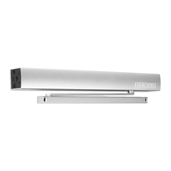
- ECturn
- User manual
-
Contents
-
Table of Contents
-
Bookmarks
Quick Links
ECturn
Translation of the original instructions
GB User manual
1
Related Manuals for GEZE ECturn
Summary of Contents for GEZE ECturn
-
Page 1
ECturn Translation of the original instructions GB User manual… -
Page 2: Table Of Contents
ECturn Contents Symbols and means of representation ………………….3 Product liability …………………………..3 Safety instructions …………………………4 Terms ………………………………5 Structure …………………………….6 Operation ……………………………..7 Functions ……………………………………7 Operating modes ………………………………..7 Button programme switch TPS (optional)………………………….8 What to do if … ? ………………………….9 Cleaning and maintenance ……………………..10…
-
Page 3: Symbols And Means Of Representation
ECturn Symbols and means of representation Symbols and means of representation Warnings In these instructions, warnings are used to warn against material damage and injuries. Always read and observe these warnings. Observe all the measures that are marked with the warning symbol and warning word.
-
Page 4: Safety Instructions
DIN VDE 0100-610. Exception: If the ECturn swing door drive is connected to the mains voltage by the mounted power plug, the connection does not have to be carried out by a qualified electrician.
-
Page 5: Terms
ECturn Terms Terms Term Statement Hinge side That side of the door at which the hinges from which the door leaf is suspended are located. Usually that side of the door located in the opening direction. Opposite hinge side That side of the door that lies opposite the hinge side. Usually that side of the door located in the closing direction.
-
Page 6: Structure
Structure ECturn Structure System parts and options The door drive unit can be mounted in transom mounting at the lintel or in door panel mounting on the door à panel. The door drive is available as a 1-leaf version. à…
-
Page 7: Operation
(depending on the charging state of the battery and frequency with which the door is used). For setting of the swing door drive with battery operation after a power failure refer to the ECturn wiring dia- gram (ID No. 134079).
-
Page 8: Button Programme Switch Tps (Optional)
Operation ECturn Button programme switch TPS (optional) Can be connected additionally to the internal programme switch. At the button programme switch, the system operating mode is selected and the corresponding programme is displayed. The desired operating mode can be selected by pressing the but- tons.
-
Page 9: What To Do If
ECturn What to do if … ? What to do if … ? Problem Cause Remedy Door only opens and closes Obstruction on the sliding Remove obstruction and check door leaf for ease of movement. slowly path Safety sensor close (SIS) Clean the Safety sensor close.
-
Page 10: Cleaning And Maintenance
Anodised surfaces Wipe with non-alkaline potassium soap (pH value 5.5…7) Maintenance The owner must ensure that the system functions properly. GEZE offers maintenance contracts with the following services: Inspect fastening elements for firm seating à Carry out miscellaneous adjustment work à…
-
Page 11: Technical Data
ECturn Technical data Technical data Opening speed 0 °/s … 45 °/s Closing speed 0 °/s … 45 °/s Electrical connection values 110 – 230 V; 50 – 60 Hz pursuant to DIN IEC 38 Connected load Rated voltage 230 W max.
-
Page 12
Høje Taastrup Boulevard 53 E-Mail: office-india@geze.com Niederlassung West China 2630 Taastrup Italy Tel. +45(0)46-323324 Nordsternstraße 65 GEZE Industries (Tianjin) Co., Ltd. Fax +45(0)46-323326 45329 Essen Shuangchenzhong Road GEZE Italia Srl Tel. +49 (0) 201-83082-0 Beichen Economic Development Via Giotto, 4 E-Mail: danmark.se@geze.com…
-
Hafele
E-drive Series
1HDE 14.12.2012 Deutsch ………………………………………………………………………………. 2English………………………………………………………………………………. 10Français…………………………………………………………………………….. 18 …
E-drive Series Door Opening System, 49
-
Besam
OPB
besam~IIo. v,,-.’…..-«»……,.- ManualGB-1126Swing Door OperatorOPB~-~i:]-=1~»»»—»»’)-~~lii»~=lI,! Iii1’1—-:1I;-1Ii;f ‘: 1, ,i’l I1~ IIi •~ :j — ; I ~ iI’I ‘1’! :,I::t:11′-‘— -,,,’ ~——-& …
OPB Door Opening System, 9
-
PDQ
6300M/MF
16300M/MF EXIT INSTALLATION INSTRUCTIONMORTISE DEVICEPhone: 833-2-PDQTEC | www.pdqlocks.com2. DOOR PREPARATION Prepare the door for the mortise lock using the 6300M/MF template in box. Refer to trim template if installing trim. Install the mortise case and secure using two (2) #12-24 combo screws supplied i …
6300M/MF Door Opening System, 3
-
hager
4700 Series
Page 1 of 3 4700 Series Rim Exit Device Installaon Instrucons Grade 1 I-ED00790 Rev: 3 Rev Date: 7/16/2018 DEVICES COVERED IN THIS DOCUMENT: 4700R Rim Exit Device 4700RF Fire-Rated Rim Exit Device Overview SINGLE DOOR DOUBLE DOOR DOUBLE DOOR WITH MULLION Tools Required METAL WOOD SCREWS SEX BOLTS …
4700 Series Door Opening System, 3
-
Brinsea
Chick Safe eco
1 IMPORTANT INSTALLATION NOTES! The door must be attached to the opener BEFORE installing the batteries. Do not fit the batteries until the ChickSafe and door are fully installed. The door must be lifted and held in the open position before attaching the cord. The ChickSafe is supplied with the cord woun …
Chick Safe eco Pet Care Product, 5
Recommended Documentation:
- Manuals
- Brands
- GEZE Manuals
- Door Opening System
- ECturn
- Wiring diagram
-
Contents
-
Table of Contents
-
Bookmarks
Quick Links
ECturn
GB Wiring diagram
1
Related Manuals for GEZE ECturn
Summary of Contents for GEZE ECturn
-
Page 1
ECturn GB Wiring diagram… -
Page 2: Table Of Contents
ECturn Table of contents Symbols and means of representation ………………….4 Warnings ……………………………………4 Further symbols and means of representation ……………………….4 Validity …………………………….4 Product liability …………………………..4 Notes ………………………………5 Important safety instructions …………………………….5 Installation notes ………………………………..5 Safety-conscious working ………………………………5 Inspection of installed system …………………………….5 Disposal of the door system…………………………….6…
-
Page 3
Commissioning the drive with GC 338 …………………………27 Parameter menu …………………………28 20.1 Value table for service LEDs and display programme switch ………………….30 Fault messages …………………………31 ECturn system ………………………….. 33 22.1 Transom installation ………………………………. 33 22.2 Door leaf installation ………………………………33 22.3… -
Page 4: Symbols And Means Of Representation
Symbols and means of representation ECturn Symbols and means of representation Warnings In these instructions, warnings are used to warn against material damage and injuries. Always read and observe these warnings. Observe all the measures that are marked with the warning symbol and warning word.
-
Page 5: Notes
à Only specialists authorised by GEZE are permitted to carry out installation, commissioning and maintenance work. à If unauthorised changes made to the system, GEZE cannot be made liable in any way whatsoever for any resulting damages. à GEZE is not liable if products from other manufacturers are used with GEZE equipment. In addition, only origi- nal GEZE parts may be used for repair and maintenance work.
-
Page 6: Disposal Of The Door System
Please return waste batteries and rechargeable bat- teries to a communal collection point or retailer. Following use, you may return any batteries or rechargeable batteries received from us by post. The address is: GEZE GmbH, Incoming Goods, Reinhold-Vöster-Str. 21-29, 71229 Leonberg/Germany. Abbreviations Wire colours…
-
Page 7: Supply Terminals
ECturn Supply terminals Supply terminals RS485 RS4 8 5 — B T ST RS4 8 5 — A 2 4 VSENS 2 4 V PA1 B P E1 PA1 A 2 4 V 24VTOE 2 4 VSENS T ST 2 4 VSENS…
-
Page 8: Safety Sensor Opening And Closing
Safety sensor opening and closing ECturn Safety sensor opening and closing à At detection the output of the sensors is open (GND is applied to the SIS or SIO input). Check function and correct setting of the sensors when putting into service and when servicing the assembly.
-
Page 9: Safety Sensor Gc 334
ECturn Safety sensor opening and closing 6.1.2 Monitoring opening à Sensor for monitoring the opening of the door. Mount on the hinge side of the door leaf. Connection of the GC 338 sensor as for «opening and closing», but the second sensor strip (S and E) is not ap- plicable.
-
Page 10
Safety sensor opening and closing ECturn 6.2.1 Monitoring opening and closing Set the parameters: à 13 (safety closing) to for «SIS» or to for «SIS and K». à 14 (safety opening) to for «SIO». à 15 (testing) to for «testing with GND»… -
Page 11: Safety Sensor Gc 335
ECturn Safety sensor opening and closing Safety sensor GC 335 à GC 335 master module, mat. no. 128074 GC 335 Extension kit (slave module with accessories), mat. no. 128072 à Follow mounting instructions à Accessories: à GC 332 adapter, mat. no. 124035 à Spotfinder, mat. no. 112321 Use the test specimen, mat. no. 120190, to set the sensing field.
-
Page 12: Contact Sensor Authorised
Contact sensor authorised ECturn 6.3.2 Monitoring opening Set the parameters: GC335 à Set 13 (safety closing) to for «no SIS». Slaves à Set 14 (safety opening) to for «SIO». à Set 15 (testing) to for «testing with 24V». 60mA 24VSENS…
-
Page 13: Contact Sensor
ECturn Contact sensor Contact sensor à The K input is only active in the AU mode of operation. à The contact sensor function can also be actuated via the radio module WRB-5, Channel 1 (see chapter 10.1.1, “Radio channel FK1”).
-
Page 14: Push Button (Potential-Free Contact)
Push And Go ECturn Push button (potential-free contact) à Plastic elbow switch, white, mat. no. 114078 à Plastic elbow switch, stainless steel, mat. no. 114077 4VSENS à Stainless steel elbow switch, mat. no. 119899 à Stainless steel elbow switch LS 990, surface-mounted, mat.
-
Page 15: Radio Control
ECturn Radio control Radio control Observe the installation and service instructions of the GEZE Automatic Wireless Programme, mat. no. 135193. à Radio reception board WRB-5, mat. no. 135170 à 1-channel wireless transmitter WTH-1, mat. no. 131209 WRB-5 STAT à 2-channel wireless transmitter WTH-2, mat. no.
-
Page 16: Configurable Input
Configurable input ECturn Configurable input PE is a configurable input. The function can be set via the service menu (see chapter 20, “Parameter menu”). 11.1 Sabotage à The configurable input PE can be used as a sabotage input e.g. for monitoring a contact sensor authorised with sabo- tage contact.
-
Page 17: Stop
ECturn Programmable output 11.4 Stop à The configurable input PE can be used as the stop input. à When the stop switch is actuated, the contact is closed (24 V applied to the PE input). à The door stops immediately as soon as the switch is acti- vated.
-
Page 18: Fault
Programmable output ECturn 12.2 Fault Set the parameters: à Set 10 (configurable output) to for the PA1B «fault» function. à The output contact closes as soon as the con- PA1A trol detects a system fault. At the same time the…
-
Page 19: Further Functions
à LEDs (1) for mode of operation display an error code if a fault occurs (see chapter 21, “Fault messages”). à The mode of operation shop closing-time is not available with ECturn. à OF, NA, AU, DO modes of operation Follow installation instructions, mat.
-
Page 20: Mains Connection
Mains fuse provided on site Main switch provided on site (optional) Earth-pin power socket (provided on site) ECturn door drive 14.3 Door leaf installation à Door transmission cable ECturn, mat. no. 135307 DCU702 GN/YE GN/YE Mains fuse provided on site…
-
Page 21: Motor
Set the operating mode to OFF. Switch off the drive at the power switch or unplug the earth-pin power plug from the mains socket. Remove the rechargeable battery plug at the DCU700 control. à DCU700 ECturn battery, mat. no. 131473 AKKU AKKU 19,2 V à…
-
Page 22: Control
Opening of the control and removal of the control circuit board DCU700 as well as connection of the PCB DCU702 to the power pack of the control may only be carried out by GEZE-authorised personnel. à Connection board DCU702, mat. no. 132444 The connection board DCU702 is located in the side cap of the drive.
-
Page 23: Low-Energy Operation — Automatic Operation
«1-leaf single-action door with guide rail, low-energy operation» (factory setting). à or to for «1-leaf single action door with link arm, low-energy operation». The range of application of the ECturn is limited to: à Leaf weight < 120 kg à 0.6 m < Leaf width < 1.1 m This limiting case is used for the presetting of low-energy operation.
-
Page 24: Automatic Operation
Low-energy operation – automatic operation ECturn 18.1.1 Optimising of the speeds in low-energy operation Higher speeds can be set for lighter and/or narrower door leaves. The diagram shows the maximum speeds al- lowed depending on the leaf width and leaf weight.
-
Page 25: Closing Torque And Door Closing Function
ECturn Commissioning and service 18.3 Closing torque and door closing function A constant closing torque in the range of 0 to 14 Nm can be set using parameter 22 . This closing torque then acts constantly in the closed position and if the door is opened manually (Push And Go deactivated).
-
Page 26: Service Buttons S1 And S2
Reset the values to the factory settings Set parameter 24 (factory settings) to 19.3 Pre-conditions for commissioning à Installation is complete (see installation instructions ECturn, mat. no. 134078). à Electrical installation is complete. à Sensors are correctly programmed and aligned.
-
Page 27: Commissioning The Drive With Gc 338
ECturn Commissioning and service End learning: à With S1, S2: Press button S1 for 2 s. à With DPS: Press the button. A confirmation signal will sound. The opening angle of the door is now known to the control.
-
Page 28: Parameter Menu
Parameter menu ECturn Parameter menu No. DPS Service LEDs Parameters Encoding Value ○ ○ ○ ● Opening speed 01 02… 10 9°/s, 18 °/s, …, 90°/s ○ ○ ● ○ 01 02… 10 9°/s, 18 °/s, …, 90°/s Closing speed ○…
-
Page 29
ECturn Parameter menu No. DPS Service LEDs Parameters Encoding Value ** ○ ○ ○ ● No function Power failure in Open and switch off Close and switch off Battery operation 15 min ** ○ ○ ● ○ 01 … 04 … -
Page 30: Value Table For Service Leds And Display Programme Switch
Parameter menu ECturn 20.1 Value table for service LEDs and display programme switch Service LEDs ○ ○ ○ ○ ○ ○ ○ ○ ○ ● ○ ○ ○ ● ○ ○ ○ ○ ● ● ○ ○ ● ○ ○…
-
Page 31: Fault Messages
ECturn Fault messages Fault messages Service LEDs Error group Cause Behaviour of the drive 5 4 3 2 1 ○ ○ ○ ○ ○ ○ ○ ○ ○ ○ – Operating Drive is switched off. voltage ○ ○ ○ ○…
-
Page 32
Fault messages ECturn Service LEDs Error group Cause Behaviour of the drive 5 4 3 2 1 ○ ○ ● ● ● * ● ○ ● ○ Motor ro- No pulse from the rotary Door leaf is braked by the motor and… -
Page 33: Ecturn System
ECturn ECturn system ECturn system 22.1 Transom installation ECturn 22.2 Door leaf installation ECturn…
-
Page 34: System Key
22.3 System key Abbreviations Mains voltage, mains fuse 10 A, power 75 W Safety sensor strip Door transmission (supplied by GEZE, sensor strip) Door opener with deadbolt contact Programme switch, external (TPS) Key operated push button for TPS Contact sensor K (e.g. button)
-
Page 35
ECturn Symbols and means of representation… -
Page 36
E-Mail: finland.se@geze.com Tel. +49 (0) 7930-9294-0 www.geze.com Fax +49 (0) 7930-9294-10 Baltic States Iberia E-Mail: sk.de@geze.com GEZE GmbH Baltic States office GEZE Iberia S.R.L. Scandinavia – Denmark E-Mail: office-latvia@geze.com E-Mail: info@geze.es GEZE Danmark www.geze.com www.geze.es E-Mail: danmark.se@geze.com GEZE GmbH www.geze.dk…

ECturn Inside
EN Installation and service instructions
1

ECturn Inside
Contents
Symbols and means of representation.........................................................................................................................3
Product liability.....................................................................................................................................................................3
Reference documents.........................................................................................................................................................3
2
1
Safety............................................................................................................................................................................3
1.1
1.2
1.3
1.4
1.5
Intended use........................................................................................................................................................................................................3
Safety instructions.............................................................................................................................................................................................4
Safety conscious working...............................................................................................................................................................................4
Inspection of the installed system...............................................................................................................................................................4
Environmentally conscious working...........................................................................................................................................................4
2
Tools and aids............................................................................................................................................................5
3
Supplied by GEZE.....................................................................................................................................................5
4
Components..............................................................................................................................................................6
4.1
Overview...............................................................................................................................................................................................................6
5
Dimensions.................................................................................................................................................................7
5.1
5.2
5.3
5.4
Dimensions when installed in wooden door leaf..................................................................................................................................7
Dimensions when installed in wooden frame.........................................................................................................................................9
Dimensions when installed in metal door............................................................................................................................................. 12
Dimensions when installed in metal frame........................................................................................................................................... 14
6
Installation............................................................................................................................................................... 16
6.1
6.2
6.3
Installation type wood.................................................................................................................................................................................. 16
Installation type metal.................................................................................................................................................................................. 23
Install optional features................................................................................................................................................................................ 25
7
Commissioning...................................................................................................................................................... 29
7.1
7.2
7.3
Collision test..................................................................................................................................................................................................... 29
Opening restrictor.......................................................................................................................................................................................... 29
Teach the drive................................................................................................................................................................................................. 29
8
Adaptation possibilities...................................................................................................................................... 29
8.1
8.2
During planning.............................................................................................................................................................................................. 29
During installation (on site)......................................................................................................................................................................... 29
9
Notes.......................................................................................................................................................................... 30
ECturn Inside
Safety
Symbols and means of representation
Further symbols and means of representation
Important information and technical notes are especially highlighted to explain correct operation.
Symbol
Meaning
means "Important Information";
Information on avoiding material damage, understanding a concept or optimising workflows.
means "additional information"
XX
Symbol for an action: Here you have to do something.
XX If there are several actions to be taken, keep to the given order.
Product liability
In accordance with the manufacturer's liability for their products as defined in the German "Produkthaftungsgesetz" (Product Liability Act), the information contained in this brochure (product information and proper use,
misuse, product performance, product maintenance, obligations to provide information and instructions) is to be
noted and followed. Failure to comply releases the manufacturer from their statutory liability.
Reference documents
Mat. No.
149544
1
Type
Wiring diagram
Name
ECturn Inside
Safety
To ensure personal safety, it is important to follow these safety instructions.
These instructions must be kept.
1.1
Intended use
The ECturn Inside is intended as a swing door drive for integration in the door leaf or frame.
The ECturn Inside is suitable:
àà solely for use in dry rooms
àà for internal applications in public buildings
àà in private areas
àà for wooden and glass doors.
The ECturn Inside
àà must not be used on fire doors or smoke control doors,
àà must not be used for potentially explosive areas.
Any improper use such as permanent manual operation, as well as any modification to the product, is not permitted.
3
Safety
1.2
ECturn Inside
Safety instructions
àà The mandatory installation, maintenance and repair work must be performed by properly trained personnel
authorised by GEZE.
àà The country-specific laws and regulations are to be observed during safety-related tests.
àà GEZE is not liable for any injuries or damage whatsoever resulting from unauthorised changes to the system.
àà GEZE is not liable if products from other manufacturers are used with GEZE equipment.
àà Furthermore, only original GEZE parts may be used for repair and maintenance work.
àà The connection to the power supply must be made by a professional electrician. Perform the power connection and equipment earth conductor test in accordance with VDE 0100 Part 610.
àà Use a customer-accessible 10-A overload cut-out as the line-side disconnecting device.
àà In compliance with Machinery Directive (2006/42/EC), a risk analysis must be performed and the door system
identified in accordance with CE Marking Directive 93/68/EEC before the door system is commissioned.
àà Observe the latest versions of guidelines, standards and country-specific regulations, in particular:
àà ASR A1.7 "Guidelines for doors and gates"
àà DIN 18650 "Building hardware – Automatic door systems"
àà Accident-prevention regulations, especially BGV A1 "General regulations" and BGV A2 "Electrical systems
and equipment"
àà VDE 0100; Part 610 "Erection of low-voltage installations"
àà DIN EN 60335-2-103 "Safety of electrical devices for home use and similar purposes; special requirements
for drives for gates, doors and windows"
àà The relevant regional building regulations must be consulted with regard to widths of escape routes.
1.3
Safety conscious working
àà
àà
àà
àà
àà
àà
àà
àà
1.4
Secure workplace against unauthorised entry.
Use only cables prescribed in the cable plan provided. Lay shields in accordance with the wiring diagram.
Secure loose, internal drive cables with cable ties.
Before working on the electrical system:
àà Disconnect the drive from the 230 V mains and check to ensure that it is not supplied with power.
àà Disconnect the control unit from the 24 V battery.
àà Note that if an uninterruptible power supply (UPS) is used, the system will still be supplied with power
despite the fact that the power supply is disconnected.
Always use insulated wire-end ferrules for wire cores.
Attach safety stickers to glass door leaves.
Danger of injury by broken glass!
Danger of injury due to sharp edges in the drive!
Inspection of the installed system
Measures for security and prevention of pinching, impact, shearing or drawing-in spots:
àà Check the functioning of safety sensors and movement detectors.
àà The detection field of the movement detector in the direction of the emergency exit must cover the opening
width x 1.5 m in front of the door.
àà Check protective earth connection to all metal parts that can be touched.
àà Perform a safety analysis (risk analysis).
1.5
Environmentally conscious working
àà When disposing of the door system, separate the different materials and have them recycled.
àà Do not dispose of batteries and storage cells with household waste.
àà Comply with the statutory regulations when disposing of the door system and the batteries/rechargeable batteries.
Recommendation: Set up according to specifications from sample chapters.
4
ECturn Inside
2
Tools and aids
Tools and aids
Tool
Size
Allen key
3 mm, 4 mm, 5 mm
Phillips screwdriver
PZ1, PZ2
Slotted screwdriver
2 mm
Side-cutting pliers
Wire stripper/crimping tool
Display programme switch
3
Supplied by GEZE
Pos.
1
2
3
4
5
6
7
8
9
10
11
12
13
–
Designation
Cover for the motor drive control
Back check (mat. no. 129343)
Guide rail and lever with installation material
Separate programme switch (optional)
Fixture for battery (optional)
Battery (optional)
Control unit
Motor drive control
Supply cable, inside door 2.5 m
Electric installation material
Cable transition (optional)
Supply cable (supplied by customer)
Power supply (flush-mounted)
Installation material
Further optional components can be included with the scope supplied by GEZE.
5
Components
ECturn Inside
4
Components
4.1
Overview
1
2
3
4
5
6
7
6
Cover for the motor drive control
Back check
Guide rail and lever
Separate programme switch (optional)
Fixture for battery (optional)
Battery (optional)
Control unit
8
9
10
11
12
13
Motor drive control
Supply cable, inside door 2.5 m
Electric installation material
Cable transition (optional)
Supply cable (supplied by customer)
Power supply (flush-mounted)
ECturn Inside
Dimensions
5.1
Dimensions when installed in wooden door leaf
5.1.1
Main dimensions
Dimensions
5
Spindle extension (mm)
11
without
17
6
24
13
27
16
31
20
Installation location
5.1.2
Dimensions K
(mm)
1
2
3
4
5
6
7
8
9
Lever
Guide rail
Separate programme switch (optional)
Control unit
Rechargeable battery
Motor drive control
Door hinge
Internal cable Ø 6.5 mm for low voltage 24 V
Cable transition and separating point
7
Dimensions
Prepared frame
5.1.3
ECturn Inside
*)
Preparation of door leaf
5.1.4
Dimensions or positions can deviate depending on the door type
8
*)
Dimensions or positions can deviate depending on the door type
1
2
Rebate for programme switch
Rebate for programme switch
ECturn Inside
5.1.5
Dimensions
Safety sensors
XX
Make sure that fixing screws and drill holes do not cross the motor drive control.
*)
Dimensions or positions can deviate depending on the door type
1
2
3
4
Safety sensor "Open"
Safety sensor "Close"
Drill hole Ø 8 mm for connection cable for the "Close" sensor
Drill hole Ø 8 mm for control unit connector cable.
5.2
Dimensions when installed in wooden frame
5.2.1
Main dimensions
*)
Dimensions K
(mm)
Spindle extension (mm)
11
without
17
6
24
13
27
16
31
20
Dimensions or positions can deviate
depending on the door type
9
Dimensions
5.2.2
ECturn Inside
Installation location
1
2
3
4
5
6
Prepared frame
5.2.3
Cable Ø 6.5 mm in the frame for low voltage
Motor drive control
Control unit
Guide rail
Lever
Door hinge
*)
10
Dimensions or positions can deviate depending on the door type
ECturn Inside
5.2.4
Dimensions
Preparation of door leaf
5.2.5
*)
Dimensions or positions can deviate depending on the door type
1
Rebate for lever
Safety sensors
XX
Make sure that fixing screws and drill holes do not cross the motor drive control.
1
2
3
4
5
Safety sensor "Open"
Safety sensor "Close"
Connector cable to the control unit
Drill hole Ø 8 mm for control unit connector cable.
Drill hole Ø 8 mm for connection cable for the "Close" sensor
11
Dimensions
ECturn Inside
5.3
Dimensions when installed in metal door
5.3.1
Main dimensions
*)
5.3.2
Spindle extension (mm)
16
without
22
6
29
13
32
16
36
20
Dimensions K
(mm)
Dimensions or positions can deviate
depending on the door type
Installation location
1
2
3
4
5
12
Lever
Guide rail
Control unit
Rechargeable battery
Motor drive control
6
7
8
Door hinge
Internal connection cable Ø 6.5 mm for low
voltage 24 V
Cable transition and separating point
ECturn Inside
5.3.3
Dimensions
Prepared frame
*)
5.3.4
Dimensions or positions can deviate depending on the door type
Preparation of door leaf
1
Rebate for programme switch
13
Dimensions
5.3.5
ECturn Inside
Safety sensors
XX
Make sure that fixing screws and drill holes do not cross the motor drive control.
1
2
3
4
Safety sensor "Open"
Safety sensor "Close"
Drill hole Ø 8 mm for control unit connector cable.
Drill hole Ø 8 mm for connection cable for the "Close" sensor
5.4
Dimensions when installed in metal frame
5.4.1
Main dimensions
14
Dimensions K
(mm)
Spindle extension (mm)
16
without
22
6
29
13
32
16
36
20
ECturn Inside
5.4.2
Dimensions
Installation location
1
2
3
4
5
6
Prepared frame
5.4.4
5.4.3
Cable Ø 6.5 mm in the frame for low voltage
Motor drive control
Control unit
Guide rail
Lever
Door hinge
Preparation of door leaf
*)
Dimensions or positions can deviate depending on the door type
15
Installation
5.4.5
ECturn Inside
Safety sensors
XX
Make sure that fixing screws and drill holes do not cross the motor drive control.
1
2
3
4
5
Safety sensor "Close"
Safety sensor "Open"
Drill hole Ø 8 mm for control unit connector cable (5).
Drill hole Ø 8 mm for connection cable for the "Open" sensor
Connector cable to the control unit
6
Installation
6.1
Installation type wood
6.1.1
Preparatory work
XX
XX
6.1.2
16
Install the power supply and route low voltage to the cable transition.
Install the cable transition.
Installation on the door leaf
XX
Install the mounting bracket on the motor drive control.
XX
Install the motor drive control in the door leaf.
ECturn Inside
Installation
XX
Install the control unit.
XX
Connect the tachometer cable of the motor drive control.
17
Installation
ECturn Inside
XX
Connect the 24V cable of the motor drive control.
If a radio board (optional) is used:
XX Now install the radio board, see page 28.
18
ECturn Inside
Installation
Electrical connection
XX Push the 6-wire cable (1) (2x 1 mm² for 24 V / 4x 0.25 mm² for door opener, contact sensor etc.) into the prepared door passage from above and through the cable transition.
In the case of metal doors, this cable is already inserted when the door is built.
Route cable (1) along the motor drive control (arrow) to the control circuit board (2).
XX Do not shorten the cable (1) too much.
Leave the length of the cords not required so that all the terminals of the control circuit board can be reached if
necessary later.
XX
XX
Strip both 24V cords, fit with 1 mm² insulated wire end sleeves and connect to the connector.
Insert the connector into the control circuit board.
19
Installation
ECturn Inside
XX
Route the cable (4) further through the door leaf and the cable transition of the door leaf.
XX
Route the cable (4) through the cable transition (5) of the frame.
Secure with strain relief (7).
Use the cable (4) to form a loop near the interface (8).
XX
Make sure that the loop is sufficiently large to prevent any strain on the cable when the door is opened.
XX
XX
Disconnect the cable.
Strip the cable ends and integrate connector (5).
XX
Use 1 mm² wire end sleeves.
XX
XX
20
ECturn Inside
Installation
Installing the guide rail
21
Installation
XX
ECturn Inside
Connect lever with motor drive control.
XX
Make sure that the safety washer (1) is fitted.
22
ECturn Inside
Installation
6.2
Installation type metal
6.2.1
Preparatory work
See Section 6.1.1.
6.2.2
Installation on the door leaf
XX
Install the mounting bracket on the motor drive control.
23
Installation
ECturn Inside
XX
Install the motor drive control in the door leaf.
XX
Route the cable strand from the motor to the control unit.
The further steps are similar to the ones for wood, section 6.1.
XX Connect the motor drive control, see 17.
XX Electrical connection, see 19.
XX Mount the guide rail, see 21.
XX Connect the lever to the motor drive control, see 22.
24
ECturn Inside
6.3
Install optional features
6.3.1
Rechargeable battery
Installation
25
Installation
6.3.2
ECturn Inside
Separate programme switch
26
ECturn Inside
Installation
27
Installation
6.3.3
ECturn Inside
Radio board
28
ECturn Inside
7
Commissioning
7.1
Collision test
Commissioning
XX Close the door carefully by hand and open it again.
During movement, no components may scrape or jam.
7.2
Opening restrictor
Fix the stop with thrust in the guide rail at a door opening of max. 110° (see „Installing the guide rail“ auf Seite
21).
XX During teaching, make sure that the door does not slam into the thrust but rather comes to a standstill beforehand.
Alternatively, a door stopper can be installed.
XX
7.3
Teach the drive
If no contact sensor (radio module, push-button switch or similar) is used:
XX Choose "Push & Go" in the parameter menu.
The teaching process is described in the ECturn wiring diagram.
XX
XX
XX
XX
XX
XX
XX
XX
XX
XX
XX
XX
Open the door a little.
Remove the control unit cover and allow to dangle from the cable.
Connect the display programme switch with the RS485 socket.
Request the Teach menu item (audible signal).
Remove the DPS connector.
Move the door into the closed position by hand (1st reversing point).
Move the door into the required open position by hand (2nd reversing point).
Move the door near to the closed position.
Connect the display programme switch with the RS485 socket.
Press the enter key and quit the teaching program (audible signal).
Pull the DPS connector off and replace the control unit cover.
Move the door into the closed position by hand (drive knows its start position).
8
Adaptation possibilities
8.1
During planning
The distance between the guide rail and drive can be enlarged by means of the lever with spindle extension (6
mm, 13 mm, 16 mm, 20 mm).
8.2
During installation (on site)
Adjustment of the distance between the drive (door) and the guide rail (frame) is not easy after installation has
been completed.
When the ECturn Inside is installed in a wooden door leaf, the distance can be reduced by shimming the motor
drive control if necessary.
29
Notes
9
30
ECturn Inside
Notes
ECturn Inside

31
Germany
GEZE Sonderkonstruktionen GmbH
Planken 1
97944 Boxberg-Schweigern
Tel. +49 (0) 7930-9294-0
Fax +49 (0) 7930-9294-10
E-Mail: [email protected]
Baltic States
GEZE GmbH Baltic States office
Dzelzavas iela 120 S
1021 Riga
Tel. +371 (0) 67 89 60 35
Fax +371 (0) 67 89 60 36
E-Mail: [email protected]
Hungary
GEZE Hungary Kft.
Bartók Béla út 105-113.
Budapest
H-1115
Tel. +36 (1) 481 4670
Fax +36 (1) 481 4671
E-Mail: [email protected]
GEZE GmbH
Niederlassung Nord-Ost
Bühringstraße 8
13086 Berlin (Weissensee)
Tel. +49 (0) 30-47 89 90-0
Fax +49 (0) 30-47 89 90-17
E-Mail: [email protected]
Benelux
GEZE Benelux B.V.
Steenoven 36
5626 DK Eindhoven
Tel. +31-(0)40-26 290-80
Fax +31-(0)40-26 290-85
E-Mail: [email protected]
GEZE GmbH
Niederlassung West
Nordsternstraße 65
45329 Essen
Tel. +49 (0) 201-83082-0
Fax +49 (0) 201-83082-20
E-Mail: [email protected]
Bulgaria
GEZE Bulgaria - Trade
Representative Office
61 Pirinski Prohod, entrance „B“,
4th floor, office 5,
1680 Sofia
Tel. +359 (0) 24 70 43 73
Fax +359 (0) 24 70 62 62
E-Mail: [email protected]
Iberia
GEZE Iberia S.R.L.
Pol. Ind. El Pla
C/Comerc, 2-22, Nave 12
08980 Sant Feliu de Llobregat (Barcelona)
Tel. +34 9-02 19 40 36
Fax +34 9-02 19 40 35
E-Mail: [email protected]
GEZE GmbH
Niederlassung Mitte
Adenauerallee 2
61440 Oberursel (b. Frankfurt)
Tel. +49 (0) 6171-63610-0
Fax +49 (0) 6171-63610-1
E-Mail: [email protected]
GEZE GmbH
Niederlassung Süd-West
Breitwiesenstraße 8
71229 Leonberg
Tel. +49 (0) 7152-203-594
Fax +49 (0) 7152-203-438
E-Mail: [email protected]
GEZE GmbH
Niederlassung Süd-Ost
Parkring 17
85748 Garching bei München
Tel.: +49 (0) 89-120 07 42-50
Fax.: +49 (0) 7152-203-77050
GEZE Service GmbH NL Süd-West
Reinhold-Vöster-Straße 25
71229 Leonberg
Tel. +49 (0) 7152-9233-34
GEZE Service GmbH NL Nord-Ost
Bühringstraße 8
13086 Berlin (Weissensee)
Tel. +49 (0) 30-470217-32
GEZE Service GmbH NL West
Nordsternstraße 65
45329 Essen
Tel. +49 (0) 201-8 30 82 16
GEZE Service GmbH NL Mitte
Feldbergstraße 59
61440 Oberursel (b. Frankfurt)
Tel. +49 (0) 6171-63 327-0
GEZE Service GmbH NL Süd
Parkring 17
85748 Garching bei München
Tel. +49 (0) 89-120 07 42-0
Austria
GEZE Austria
Wiener Bundesstrasse 85
A-5300 Hallwang
Tel. +43/6225/87180
Fax +43/6225/87180-299
E-Mail: [email protected]
GEZE GmbH
P.O.Box 1363
Reinhold-Vöster-Straße 21–29
71229 Leonberg
Germany
China
GEZE Industries (Tianjin) Co., Ltd.
Shuangchenzhong Road
Beichen Economic Development
Area (BEDA)
Tianjin 300400, P.R. China
Tel. +86(0)22-26973995-0
Fax +86(0)22-26972702
E-Mail: [email protected]
China
GEZE Industries (Tianjin) Co., Ltd.
Branch Office Shanghai
Unit 25N, Cross Region Plaza
No. 899, Ling Ling Road,
XuHui District
200030 Shanghai, P.R. China
Tel. +86 (0)21-523 40 960
Fax +86 (0)21-644 72 007
E-Mail: [email protected]
China
GEZE Industries (Tianjin) Co., Ltd.
Branch Office Guangzhou
Room 17C3
Everbright Bank Building, No.689
Tian He Bei Road
510630 Guangzhou, P.R. China
Tel. +86(0)20-38731842
Fax +86(0)20-38731834
E-Mail: [email protected]
China
GEZE Industries (Tianjin) Co., Ltd.
Branch Office Beijing
Room 1001, Tower D
Sanlitun SOHO
No. 8, Gongti North Road,
Chaoyang District,
100027 Beijing, P.R.China
Tel. +86-(0)10-5935 9300
Fax +86-(0)10-5935 9322
E-Mail: [email protected]
France
GEZE France S.A.R.L.
ZAC de l’Orme Rond
RN 19
77170 Servon
Tel. +33-(0)1-606260-70
Fax +33-(0)1-606260-71
E-Mail: [email protected]
Tel.: 0049 7152 203-0
Fax: 0049 7152 203-310
www.geze.com
Scandinavia – Finland
Branch office of GEZE Scandinavia AB
Herralantie 824
Postbox 20
15871 Hollola
Tel. +358(0)10-40 05 100
Fax +358(0)10-40 05 120
E-Mail: [email protected]
Scandinavia – Denmark
GEZE Danmark
Branch office of GEZE Scandinavia AB
Mårkærvej 13 J-K
2630 Taastrup
Tel. +45(0)46-32 33 24
Fax +45(0)46-32 33 26
E-Mail: [email protected]
India
GEZE India Private Ltd.
MF2 & 3, Guindy Industrial Estate
Ekkattuthangal
Chennai - 600 097
Tamilnadu
Tel. +91 (0) 44 30 61 69 00
Fax +91 (0) 44 30 61 69 01
E-Mail: [email protected]
Singapore
GEZE (Asia Pacific) Pte, Ltd.
21 Bukit Batok Crescent
#23-75, Wcega Tower,
Singapore 658065
Tel. +65-6846 1338
Fax +65-6846 9353
E-Mail: [email protected]
Italy
GEZE Italia S.r.l
Via Giotto, 4
20040 Cambiago (MI)
Tel. +39(0)29 50 695-11
Fax +39(0)29 50 695-33
E-Mail: [email protected]
South Africa
GEZE Distributors (Pty) Ltd.
118 Richards Drive, Halfway House,
Ext 111, P.O. Box 7934, Midrand 1685,
South Africa
Tel. +27(0)113 158 286
Fax +27(0)113 158 261
E-Mail: [email protected]
Italy
GEZE Engineering Roma S.r.l
Via Lucrezia Romana, 91
00178 Roma
Tel. +39(0)6-72 65 311
Fax +39(0)6-72 65 3136
E-Mail: [email protected]
Poland
GEZE Polska Sp.z o.o.
ul. Annopol 21
03-236 Warszawa
Tel. +48 (0)22 440 4 440
Fax +48 (0)22 440 4 400
E-Mail: [email protected]
Romania
GEZE Romania S.R.L.
IRIDE Business Park
Str. Dimitrie Pompei nr. 9–9a
Building 10, level 2, sector 2
020335 Bucharest
Tel. +40 (0) 21 25 07 750
Fax +40 (0) 21 25 07 750
E-Mail: [email protected]
Russia
OOO GEZE RUS
Gamsonovskiy Per. 2
115191 Moskau
Tel. +7 (0) 495 933 06 59
Fax +7 (0) 495 933 06 74
E-Mail: [email protected]
Scandinavia – Sweden
GEZE Scandinavia AB
Mallslingan 10
Box 7060
18711 Täby, Sweden
Tel. +46(0)8-7323-400
Fax +46(0)8-7323-499
E-Mail: [email protected]
Scandinavia – Norway
GEZE Scandinavia AB avd. Norge
Industriveien 34 B
2073 Dal
Tel. +47(0)639-57200
Fax +47(0)639-57173
E-Mail: [email protected]
150647-00
Switzerland
GEZE Schweiz AG
Bodenackerstrasse 79
4657 Dulliken
Tel. +41-(0)62-285 54 00
Fax +41-(0)62-285 54 01
E-Mail: [email protected]
Turkey
GEZE Kapı ve Pencere Sistemleri
San. ve Tic. Ltd. Şti.
Ataşehir Bulvarı, Ata 2/3
Plaza Kat: 9 D: 84 Ataşehir
Ataşehir / İstanbul
Tel. + 90 (0) 21 64 55 43 15
Fax + 90 (0) 21 64 55 82 15
E-Mail: [email protected]
Ukraine
GEZE Ukraine TOV
ul. Viskoznaya, 17,
Building 93-B, Office 12
02094 Kiev
Tel./Fax +38 (0) 44 501 22 25
E-Mail: [email protected]
United Arab Emirates/GCC
GEZE Middle East
P.O. Box 17903
Jebel Ali Free Zone
Dubai
Tel. +971(0)4-88 33 112
Fax +971(0)4-88 33 240
E-Mail: [email protected]
United Kingdom
GEZE UK Ltd.
Blenheim Way
Fradley Park
Lichfield
Staffordshire WS13 8SY
Tel. +44(0)1543 44 30 00
Fax +44(0)1543 44 30 01
E-Mail: [email protected]
ECturn
- Скорость открывания и закрывания может адаптироваться по индивидуальным требованиям
- Электрический конечный дохлоп, ускоряющий движение двери незадолго до достижения закрытого положения
- Функция энергосбережения открывает и закрывает дверь с уменьшенной скоростью вращения и таким образом отвечает самым высоким требованиям безопасности
- Система обнаружения препятствий регистрирует касание препятствия и останавливает процесс открывания или закрывания
- Автоматический реверс возвращает дверь обратно в положение открывания при обнаружении препятствия
- Функция Push & Go (толкай и иди) запускает систему автоматического привода после легкого нажатия рукой на дверную створку
Показать больше
- Привод может использоваться со скользящей шиной или рычажной тягой
- Доступна скользящая шина для стеклянных дверей толщиной 8-10 мм
- Опциональный аккумулятор обеспечивает максимальную надежность при отключении электропитания
- Опциональная радиоплата для беспроводной активации через радиопередатчик
Свяжитесь с нами
Области применения
- Одностворчатые правые и левые распашные двери
- Распашные двери с шириной створки до 1100 мм или весом 125 кг
- Часто используемые входные и внутренние двери
- Автоматизация безрамных цельностеклянных дверей
- Монтаж на дверном полотне и на дверной коробке
- Безбарьерные входы
Данный продукт отмечен премией


Характеристики продукта
| ECturn | |
| Вес створки (макс.), одностворчатая |
125 kg |
| Ширина створки (мин.–макс.) |
650 mm — 1100 mm |
| Глубина откоса (макс.) |
200 mm |
| Наплав двери (макс.) |
50 mm |
| Тип привода |
Электромеханический |
| Угол открывания (макс.) |
110 ° |
| Левостороннее открывание (DIN слева) |
Да |
| Правостороннее открывание (DIN справа) |
Да |
| Монтаж на дверной коробке со стороны, противоположной петлевой, с рычажной тягой |
Да |
| Монтаж на дверной коробке со стороны, обратной петлевой, с роликовой шиной |
Да |
| Монтаж на дверной коробке со стороны дверных петель с роликовой рейкой |
Да |
| Монтаж на дверном полотне со стороны, противоположной петлевой, с роликовой рейкой |
Да |
| Монтаж на дверном полотне со стороны дверных петель, с роликовой рейкой |
Да |
| Монтаж на дверной створке со стороны дверных петель с рычажной тягой |
Да |
| Механический дохлоп |
Нет |
| Электрический дохлоп |
Да |
| Отключение от электросети |
Главный выключатель в приводе |
| Задержка управляющего сигнала (макс.) |
20 s |
| Номинальная мощность |
75 W |
| Блок питания для внешних потребителей тока (24 В DC) |
600 mA |
| Рабочая температура |
-15 — 50 °C |
| Влажность воздуха неконденсирующаяся (макс.) |
95 % |
| Степень защиты |
IP20 |
| Режим работы |
Автоматика, Длительное открытие, Ночь, Выкл. |
| Автоматическая функция |
Да |
| Функция низкого энергопотребления |
Да |
| С функцией сервопривода |
Нет |
| Распознавание препятствий |
Да |
| Автоматический реверс |
Да |
| Push & Go (Толкай и иди) |
регулируется |
| Пульт управления |
Интегрированный программный переключатель, Программный переключатель TPS |
| Ввод параметров |
Система управления, Программный переключатель DPS |
| Соответствие стандартам |
EN 16005 |
Варианты и крепежный материал
-
Компоненты
-
Крепежный материал
*
Примечание к демонстрируемым продуктам
Вышеупомянутые продукты могут различаться по форме, типу, характеристикам и функциональному содержанию (по конструкции, размерам, наличию, допускам, стандартам и т. п.) в зависимости от страны поставки
E-Mail
.