-
Contents
-
Table of Contents
-
Troubleshooting
-
Bookmarks
Quick Links
GA-B75-D3V
User’s Manual
Rev. 1101
12ME-B75D3V-1101R
Related Manuals for Gigabyte GA-B75-D3V
Summary of Contents for Gigabyte GA-B75-D3V
-
Page 1
GA-B75-D3V User’s Manual Rev. 1101 12ME-B75D3V-1101R… -
Page 3: Identifying Motherboard Revision
GIGABYTE’s prior written permission. Documentation Classifications In order to assist in the use of this product, GIGABYTE provides the following types of documentations: „ For quick set-up of the product, read the Quick Installation Guide included with the product.
-
Page 4: Table Of Contents
Table of Contents Box Contents ……………………6 Optional Items …………………….6 GA-B75-D3V Motherboard Layout ………………7 GA-B75-D3V Motherboard Block Diagram …………..8 Chapter 1 Hardware Installation ………………9 Installation Precautions ………………. 9 1-2 Product Specifications ………………. 10 Installing the CPU and CPU Cooler…………… 13 1-3-1 Installing the CPU ………………..13 1-3-2 Installing the CPU Cooler ………………15…
-
Page 5
Chapter 3 Drivers Installation ………………53 Installing Chipset Drivers …………….53 Application Software ………………54 Technical Manuals ………………54 Contact………………….55 System ………………….55 Download Center ………………. 56 New Program ………………..56 Chapter 4 Unique Features ……………….57 Xpress Recovery2 ………………57 BIOS Update Utilities ……………… -
Page 6: Box Contents
Box Contents 5 GA-B75-D3V motherboard 5 Motherboard driver disk 5 User’s Manual 5 Quick Installation Guide 5 Two SATA 6Gb/s cables 5 I/O Shield The box contents above are for reference only and the actual items shall depend on the product package you obtain. The box contents are subject to change without notice.
-
Page 7: Ga-B75-D3V Motherboard Layout
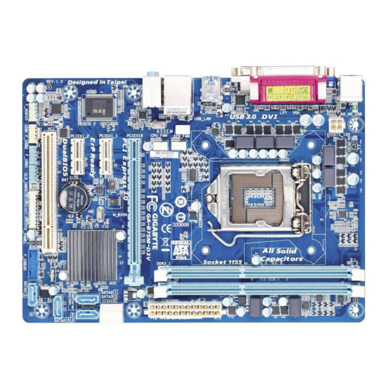
GA-B75-D3V Motherboard Layout KB_MS_USB ATX_12V_2X4 LGA1155 R_USB30 USB_LAN AUDIO PCIEX1_1 mSATA F_USB30 PCIEX16 GA-B75-D3V Atheros GbE LAN PCIEX1_2 Intel ® M_BIOS PCIEX1_3 B_BIOS CODEC SATA3 PCIEX4 SATA2 PCI1 PCI2 SPDIF_O CLR_CMOS F_AUDIO COMA SYS_FAN1 F_USB2 F_USB1 F_PANEL — 7 -…
-
Page 8: Ga-B75-D3V Motherboard Block Diagram
GA-B75-D3V Motherboard Block Diagram 1 PCI Express x16 CPU CLK+/- (100 MHz) LGA1155 DDR3 1600/1333/1066 MHz PCIe CLK Dual Channel Memory (100 MHz) PCI Express Bus 1 PCI Express x4 Dual BIOS D-Sub DVI-D 1 SATA 6Gb/s 4 SATA 3Gb/s PCI Express Bus Intel ® 1 mSATA 8 USB 2.0/1.1 Atheros…
-
Page 9: Chapter 1 Hardware Installation
Chapter 1 Hardware Installation Installation Precautions The motherboard contains numerous delicate electronic circuits and components which can become damaged as a result of electrostatic discharge (ESD). Prior to installation, carefully read the user’s manual and follow these procedures: • Prior to installation, make sure the chassis is suitable for the motherboard. •…
-
Page 10: Product Specifications
Support for non-ECC memory modules Š Support for Extreme Memory Profile (XMP) memory modules Š * To support XMP memory, you must install an Intel 22nm (Ivy Bridge) CPU. (Go to GIGABYTE’s website for the latest supported memory speeds and memory modules.) Onboard Integrated Graphics Processor: Š…
-
Page 11
Storage Interface Š Chipset: 1 x SATA 6Gb/s connector (SATA3 0) supporting up to 1 SATA 6Gb/s device 4 x SATA 3Gb/s connectors (SATA2 1~4) supporting up to 4 SATA 3Gb/s devices 1 x mSATA connector Chipset: Š U p to 4 USB 3.0/2.0 ports (2 ports on the back panel, 2 ports available through the internal USB header) * In Windows XP, the Intel USB 3.0 ports can support up to USB 2.0 transfer speed. U p to 8 USB 2.0/1.1 ports (4 ports on the back panel, 4 ports available through the internal USB headers) Internal 1 x 24-pin ATX main power connector Š… -
Page 12
* GIGABYTE reserves the right to make any changes to the product specifications and product-related information without prior notice. * Please visit GIGABYTE’s website to check the supported operating system(s) for the software listed in the «Unique Features» and «Bundled Software» columns. -
Page 13: Installing The Cpu And Cpu Cooler
Read the following guidelines before you begin to install the CPU: • Make sure that the motherboard supports the CPU. (Go to GIGABYTE’s website for the latest CPU support list.) • Always turn off the computer and unplug the power cord from the power outlet before installing the CPU to prevent hardware damage.
-
Page 14
B. Follow the steps below to correctly install the CPU into the motherboard CPU socket. Before installing the CPU, make sure to turn off the computer and unplug the power cord from the power outlet to prevent damage to the CPU. Step 1: Step 2: Remove the CPU socket cover as shown. -
Page 15: Installing The Cpu Cooler
1-3-2 Installing the CPU Cooler Follow the steps below to correctly install the CPU cooler on the motherboard. (The following procedure uses Intel boxed cooler as the example cooler.) ® Male Push Pin Direction of the Arrow Sign The Top on the Male of Female Push Pin…
-
Page 16: Installing The Memory
• Make sure that the motherboard supports the memory. It is recommended that memory of the same capacity, brand, speed, and chips be used. (Go to GIGABYTE’s website for the latest supported memory speeds and memory modules.) • Always turn off the computer and unplug the power cord from the power outlet before installing the memory to prevent hardware damage.
-
Page 17: Installing A Memory
1-4-2 Installing a Memory Before installing a memory module, make sure to turn off the computer and unplug the power cord from the power outlet to prevent damage to the memory module. DDR3 and DDR2 DIMMs are not compatible to each other or DDR DIMMs. Be sure to install DDR3 DIMMs on this motherboard.
-
Page 18: Installing An Expansion Card
Installing an Expansion Card Read the following guidelines before you begin to install an expansion card: • Make sure the motherboard supports the expansion card. Carefully read the manual that came with your expansion card. • Always turn off the computer and unplug the power cord from the power outlet before installing an expansion card to prevent hardware damage.
-
Page 19: Back Panel Connectors
Back Panel Connectors USB 2.0/1.1 Port The USB port supports the USB 2.0/1.1 specification. Use this port for USB devices such as a USB keyboard/mouse, USB printer, USB flash drive and etc. PS/2 Keyboard/Mouse Port Use this port to connect a PS/2 mouse or keyboard. D-Sub Port The D-Sub port supports a 15-pin D-Sub connector. Connect a monitor that supports D-Sub connection to this port.
-
Page 20: Internal Connectors
Internal Connectors ATX_12V_2X4 CLR_CMOS F_PANEL CPU_FAN F_AUDIO SYS_FAN1/2/3 SPDIF_O F_USB1/F_USB2 SATA3 0 F_USB30 SATA2 1/2/3/4 mSATA COMA Read the following guidelines before connecting external devices: • First make sure your devices are compliant with the connectors you wish to connect. •…
-
Page 21
1/2) ATX_12V_2X4/ATX (2×4 12V Power Connector and 2×12 Main Power Connector) With the use of the power connector, the power supply can supply enough stable power to all the components on the motherboard. Before connecting the power connector, first make sure the power supply is turned off and all devices are properly installed. The power connector possesses a foolproof design. Connect the power supply cable to the power connector in the correct orientation. -
Page 22
3/4) CPU_FAN/SYS_FAN1/SYS_FAN2/SYS_FAN3 (Fan Headers) All fan headers on this motherboard are 4-pin. Most fan headers possess a foolproof insertion design. When connecting a fan cable, be sure to connect it in the correct orientation (the black connector wire is the ground wire). The speed control function requires the use of a fan with fan speed control design. For optimum heat dissipation, it is recommended that a system fan be installed inside the chassis. -
Page 23
DEBUG PORT 6) SATA3 0 (SATA 6Gb/s Connector, Controlled by Intel B75 Chipset) The SATA connector conforms to SATA 6Gb/s standard and is compatible with SATA 3Gb/s and SATA 1.5Gb/s standard. Each SATA connector supports a single SATA device. Pin No. Definition SATA3 0 DEBUG PORT DEBUG PORT DEBUG PORT DEBUG PORT 7) SATA2 1/2/3/4 (SATA 3Gb/s Connectors, Controlled by Intel B75 Chipset) The SATA connectors conform to SATA 3Gb/s standard and are compatible with SATA 1.5Gb/s standard. Each SATA connector supports a single SATA device. -
Page 24
F_AUDIO(H) F_PANEL(NH) F_PANEL (H61M-D2) mSATA (Solid-State Drive Connector, Controlled by the Intel B75 Chipset) The mSATA connector conforms to SATA 3Gb/s standard and can connect to a single solid-state drive. BIOS Switcher (X58A-OC) DB_PORT M_SATA mSATA ACPI_CPT (GA-IVB) Voltage measurement module(X58A-OC) PWM Switch (X58A-OC) SMB_CPT 1 2 3 (GA-IVB) PCIe power connector (SATA)(X58A-OC) CLR_CMOS DIS_ME GP15_CPT (GA-IVB)
 -
Page 25: F_Panel (Front Panel Header)
10) F_PANEL (Front Panel Header) Connect the power switch, reset switch, speaker, chassis intrusion switch/sensor and system status indicator on the chassis to this header according to the pin assignments below. Note the positive and negative pins before connecting the cables. Message/Power/ Power Speaker Sleep LED Switch Hard Drive Reset Power LED Activity LED Switch Chassis Intrusion Header…
-
Page 26: Front Panel Audio Header
11) F_AUDIO (Front Panel Audio Header) The front panel audio header supports Intel High Definition audio (HD) and AC’97 audio. You may connect your chassis front panel audio module to this header. Make sure the wire assignments of the module con- nector match the pin assignments of the motherboard header. Incorrect connection between the module connector and the motherboard header will make the device unable to work or even damage it. For HD Front Panel Audio: For AC’97 Front Panel Audio: Pin No.
-
Page 27: Usb 3.0/2.0 Header
13) F_USB1/F_USB2 (USB 2.0/1.1 Headers) The headers conform to USB 2.0/1.1 specification. Each USB header can provide two USB ports via an optional USB bracket. For purchasing the optional USB bracket, please contact the local dealer. Pin No. Definition Power (5V) Power (5V) USB DX- USB DY- USB DX+ USB DY+ No Pin F_USB30 F_AUDIO(H) 14) F_USB30 (USB 3.0/2.0 Header) The header conforms to USB 3.0/2.0 specification and can provide two USB ports. For purchasing the optional 3.5″ front panel that provides two USB 3.0/2.0 ports, please contact the local dealer.
-
Page 28
DB_PORT 15) TPM (Trusted Platform Module Header) You may connect a TPM (Trusted Platform Module) to this header. Voltage measurement module(X58A-OC) w/housing Pin No. Definition Pin No. Definition LCLK LAD0 PCIe power connector (SATA)(X58A-OC) LFRAME No Pin LRESET SB3V SERIRQ LAD3 LAD2 VCC3… -
Page 29: Chapter 2 Bios Setup
To access the BIOS Setup program, press the <Delete> key during the POST when the power is turned on. To upgrade the BIOS, use either the GIGABYTE Q-Flash or @BIOS utility. Q-Flash allows the user to quickly and easily upgrade or back up BIOS without entering the operating system.
-
Page 30: Startup Screen
Startup Screen The following startup Logo screen will appear when the computer boots. Function Keys Function Keys: <DEL>: BIOS SETUPQ-FLASH Press the <Delete> key to enter BIOS Setup or to access the Q-Flash utility in BIOS Setup. <F9>: SYSTEM INFORMATION Press the <F9>…
-
Page 31: The Main Menu
The Main Menu On the main menu of the BIOS Setup program, press arrow keys to move among the items and press <Enter> to accept or enter a sub-menu. Or you can use your mouse to select the item you want. (Sample BIOS Version: F5e) Setup Menus Enter Q-Flash…
-
Page 32
BIOS Setup Menus „ M.I.T. Use this menu to configure the clock, frequency, and voltages of your CPU and memory, etc. Or check the system/CPU temperatures, voltages, and fan speeds. „ System Use this menu to configure the default language used by the BIOS and system time and date. This menu also displays information on the devices connected to the SATA ports. „ BIOS Features Use this menu to configure the device boot order, advanced features available on the CPU, and the primary display adapter. „ Peripherals Use this menu to configure all peripheral devices, such as SATA, USB, integrated audio, and integrated LAN, etc. „ Power Management Use this menu to configure all the power-saving functions. „ Save & Exit Save all the changes made in the BIOS Setup program to the CMOS and exit BIOS Setup. -
Page 33: M.i.t
M.I.T. Whether the system will work stably with the overclock/overvoltage settings you made is dependent on your overall system configurations. Incorrectly doing overclock/overvoltage may result in damage to CPU, chipset, or memory and reduce the useful life of these components. This page is for advanced users only and we recommend you not to alter the default settings to prevent system instability or other unexpected results. (Inadequately altering the settings may result in system’s failure to boot. If this occurs, clear the CMOS values and reset the board to default values.) This section provides information on the BIOS version, CPU base clock, CPU frequency, memory frequency, total memory size , CPU temperature, Vcore, and memory voltage.
-
Page 34
` M.I.T. Current Status This screen provides information on CPU/memory frequencies/parameters. ` Advanced Frequency Settings & CPU/PCIe Base Clock Allows you to manually set the CPU base clock and PCIe bus frequency in 0.01 MHz increments. (Default: Auto) Important: It is highly recommended that the CPU frequency be set in accordance with the CPU specifications. -
Page 35
` Advanced CPU Core Features & CPU Clock Ratio, CPU Frequency The settings under the two items above are synchronous to those under the same items on the Advanced Frequency Settings menu. & Intel(R) Turbo Boost Technology (Note) Allows you to determine whether to enable the Intel CPU Turbo Boost technology. Auto lets the BIOS automatically configure this setting. (Default: Auto) &… -
Page 36
& CPU Enhanced Halt (C1E) (Note 1) Enables or disables Intel CPU Enhanced Halt (C1E) function, a CPU power-saving function in system halt state. When enabled, the CPU core frequency and voltage will be reduced during system halt state to decrease power consumption. -
Page 37
` Advanced Memory Settings & Extreme Memory Profile (X.M.P.) , System Memory Multiplier (SPD), Memory (Note) Frequency(Mhz) The settings under the three items above are synchronous to those under the same items on the Advanced Frequency Settings menu. & Performance Enhance Allows the system to operate at three different performance levels. Lets the system operate at its basic performance level. -
Page 38
Channel A/B Timing Settings This sub-menu provides memory timing settings for each channel of memory. The respective timing setting screens are configurable only when DRAM Timing Selectable is set to Quick or Expert. Note: Your system may become unstable or fail to boot after you make changes on the memory timings. If this occurs, please reset the board to default values by loading optimized defaults or clearing the CMOS values. -
Page 39: Pc Health Status
` PC Health Status & Reset Case Open Status Keeps or clears the record of previous chassis intrusion status. (Default) Disabled Clears the record of previous chassis intrusion status and the Case Open field will show Enabled «No» at next boot. & Case Open Displays the detection status of the chassis intrusion detection device attached to the motherboard CI header. If the system chassis cover is removed, this field will show «Yes», otherwise it will show «No». To clear the chassis intrusion status record, set Reset Case Open Status to Enabled, save the settings to…
-
Page 40
& CPU Vcore/Dram Voltage/+3.3V/+12V Displays the current system voltages. & CPU/System Temperature Displays current CPU/system temperature. & CPU/System FAN Speed Displays current CPU/system fan speeds. & CPU Warning Temperature Sets the warning threshold for CPU temperature. When CPU temperature exceeds the threshold, BIOS will emit warning sound. Options are: Disabled (default), 60 C/140 F, 70 C/158… -
Page 41: Miscellaneous Settings
` Miscellaneous Settings & PEG — Gen X Allows you to set the operation mode of the PCI Express slots to Gen 1, Gen 2, or Gen 3. Actual operation mode is subject to the hardware specification of each slot. For example, the PCI Express x1 slots can support up to Gen 2 mode only. Auto lets the BIOS automatically configure this setting. (Default: Auto) & Legacy BenchMark Enhancement Allows you to determine whether to enhance some legacy benchmark performance.
-
Page 42: System
System This section provides information on your CPU, memory, motherboard model, and BIOS version. You can also select the default language used by the BIOS and manually set the system time. & System Language Selects the default language used by the BIOS. &…
-
Page 43: Bios Features
Enables or disables Numlock feature on the numeric keypad of the keyboard after the POST. (Default: Enabled) & Full Screen LOGO Show Allows you to determine whether to display the GIGABYTE Logo at system startup. Disabled skips the GIGABYTE Logo when the system starts up. (Default: Enabled) & PCI ROM Priority Allows you to determine which Option ROM to launch.
-
Page 44: Network Stack
& Limit CPUID Maximum (Note) Allows you to determine whether to limit CPUID maximum value. Set this item to Disabled for Windows XP operating system; set this item to Enabled for legacy operating system such as Windows NT4.0. (Default: Disabled) &…
-
Page 45: Peripherals
Peripherals & LAN PXE Boot Option ROM Allows you to decide whether to activate the boot ROM integrated with the onboard LAN chip. (Default: Disabled) & SATA Controller(s) Enables or disables the integrated SATA controllers. (Default: Enabled) & SATA Mode Selection Allows you to decide whether to configure the SATA controller integrated in the Chipset to AHCI mode.
-
Page 46: Xhci Mode
AHCI C onfigures the SATA controller to AHCI mode. Advanced Host Controller Interface (AHCI) is an interface specification that allows the storage driver to enable advanced Serial ATA features such as Native Command Queuing and hot plug. & xHCI Pre-Boot Driver The USB 3.0 ports are routed to the xHCI controller before booting to OS. (Default) Enabled The USB 3.0 ports are routed to the EHCI controller before booting to OS.
-
Page 47: Internal Graphics
& Init Display First Specifes the frst initiation of the monitor display from the installed PCI graphics card, PCI Express graphics card, or the onboard graphics. Auto Lets BIOS automatically configure this setting. (Default) IGFX Sets the onboard graphics as the first display. PEG Sets the PCI Express graphics card on the PCIEX16 slot as the first display. PCI Sets the graphics card on the PCI slot as the first display. & Internal Graphics Enables or disables the onboard graphics function. (Default: Auto) &…
-
Page 48: Trusted Computing
` Trusted Computing & TPM SUPPORT Enables or disables Trusted Platform Module (TPM). Set this item to Enable when a TPM device is installed. (Default: Disable) & OnBoard LAN Controller#1 Enables or disables the onboard LAN function. (Default: Enabled) If you wish to install a 3rd party add-in network card instead of using the onboard LAN, set this item to Disabled.
-
Page 49: Power Management
Power Management & AC BACK Determines the state of the system after the return of power from an AC power loss. The system returns to its last known awake state upon the return of the AC power. Memory Always On The system is turned on upon the return of the AC power.
-
Page 50
& ErP Determines whether to let the system consume less than 1W power in S5 (shutdown) state. (Default: Disabled) Note: When this item is set to Enabled, the following functions will become unavailable: PME event wake up, power on by mouse, power on by keyboard, and wake on LAN. &… -
Page 51: Save & Exit
Save & Exit & Save & Exit Setup Press <Enter> on this item and select Yes. This saves the changes to the CMOS and exits the BIOS Setup program. Select No or press <Esc> to return to the BIOS Setup Main Menu. &…
-
Page 52
BIOS Setup — 52 -… -
Page 53: Chapter 3 Drivers Installation
• After «Xpress Install» installs all of the drivers, a dialog box will appear asking whether to install new GIGABYTE utilities. Click Yes to automatically install the utilities. Or click No if you want to manually select the utilities to install on the Application Software page later.
-
Page 54: Application Software
Application Software This page displays all the utilities and applications that GIGABYTE develops and some free software. You can click the Install button on the right of an item to install it. Technical Manuals This page provides the content descriptions for this driver disk.
-
Page 55: Contact
Contact For the detailed contact information of the GIGABYTE Taiwan headquarter or worldwide branch offices, click the URL on this page to link to the GIGABYTE website. System This page provides the basic system information. — 55 — Drivers Installation…
-
Page 56: Download Center
The latest version of the BIOS, drivers, or applications will be displayed. New Program This page provides a quick link to GIGABYTE’s lately developed utilities for users to install. You can click the Install button on the right of an item to install it.
-
Page 57: Chapter 4 Unique Features
Chapter 4 Unique Features Xpress Recovery2 Xpress Recovery2 is a utility that allows you to quickly compress and back up your system data and perform restoration of it. Supporting NTFS, FAT32, and FAT16 file systems, Xpress Recovery2 can back up data on PATA and SATA hard drives and restore it. Before You Begin: •…
-
Page 58
Step 3: Step 4: When partitioning your hard drive, make sure to leave After the operating system is installed, click Start, unallocated space (10 GB or more is recommended; right-click the Computer and select Manage. Go to actual size requirements vary, depending on the Disk Management to check disk allocation. -
Page 59
D. Using the Restore Function in Xpress Recovery2 Select RESTORE to restore the backup to your hard drive in case the system breaks down. The RESTORE option will not be present if no backup is created before. E. Removing the Backup Step 1: Step 2: If you wish to remove the backup file, select… -
Page 60: Bios Update Utilities
@BIOS will download the latest BIOS file from the nearest @BIOS server site and update the BIOS. 4-2-1 Updating the BIOS with the Q-Flash Utility A. Before You Begin From GIGABYTE’s website, download the latest compressed BIOS update file that matches your motherboard model. Extract the file and save the new BIOS file (e.g. B75D3V.F1) to your USB flash drive or hard drive. Note: The USB flash drive or hard drive must use FAT32/16/12 file system. Restart the system. During the POST, press the <End> key to enter Q-Flash. Note: You can access Q-Flash by either pressing the <End>…
-
Page 61
B. Updating the BIOS In the main menu of Q-Flash, use the keyboard or mouse to select an item to execute. When updating the BIOS, choose the location where the BIOS file is saved. The following procedure assumes that you save the BIOS file to a USB flash drive. Step 1: 1. Insert the USB flash drive containing the BIOS file into the computer. In the main menu of Q-Flash, select Update BIOS From Drive. • The Save BIOS to Drive option allows you to save the current BIOS file. •… -
Page 62
Step 4: During the POST, press <Delete> to enter BIOS Setup. Select Load Optimized Defaults on the Save & Exit screen and press <Enter> to load BIOS defaults. System will re-detect all peripheral devices after a BIOS update, so we recommend that you reload BIOS defaults. Select Yes to load BIOS defaults Step 5: Select Save &… -
Page 63: Updating The Bios With The @Bios Utility
B. Using @BIOS Update the BIOS Using the Internet Update Function: Click Update BIOS from GIGABYTE Server, select the @BIOS server site closest to your location and then download the BIOS file that matches your motherboard model. Follow the on-screen instructions to complete. If the BIOS update file for your motherboard is not present on the @BIOS server site, please manually download the BIOS update file from GIGABYTE’s website and follow the instructions in «Update the BIOS without Using the Internet Update Function»…
-
Page 64: Easytune 6
EasyTune 6 GIGABYTE’s EasyTune 6 is a simple and easy-to-use interface that allows users to fine-tune their system settings or do overclock/overvoltage in Windows environment. The user-friendly EasyTune 6 interface also includes tabbed pages for CPU and memory information, letting users read their system-related information without the need to install additional software. The EasyTune 6 Interface Tabs Information Function The CPU tab provides information on the installed CPU and motherboard.
-
Page 65: Q-Share
Internet resources. Directions for using Q-Share After installing Q-Share from the motherboard driver disk, go to Start>All Programs>GIGABYTE>Q-Share.exe to launch the Q-Share tool. Find the Q-Share icon in the notification area and right-click on this icon to configure the data sharing settings.
-
Page 66: Auto Green
Auto Green Auto Green is an easy-to-use tool that provides users with simple options to enable system power savings via a Bluetooth cell phone. When the phone is out of the range of the computer’s Bluetooth receiver, the system will enter the specified power saving mode. The Configuration dialog box: First, you have to set your Bluetooth cell phone as a portable key.
-
Page 67: Ez Setup
Installing EZ Setup After inserting the GIGABYTE motherboard driver disk, click Express Install to install all motherboard drivers. After completion, go to the New Program menu and click Install on the right of the EZ Setup application to install it.
-
Page 68: Installing Ez Smart Response
4-6-1 Installing EZ Smart Response A. System Requirements 1. An Intel Chipset-based motherboard supporting this feature (Note 1) 2. An Intel Core series processor 3. RAID enabled for the Intel SATA controllers in BIOS Setup 4. A conventional SATA disk and an SSD (Note 2) 5.
-
Page 69: Installing Ez Rapid Start
4-6-2 Installing EZ Rapid Start A. System Requirements 1. Intel Rapid Start Technology enabled in BIOS Setup 2. Windows 7 with SP1 3. An SSD with size larger than the total system memory 4. AHCI/RAID mode supported (please note if the SSD has been assigned as a member of a RAID array, it cannot be used to set up Intel Rapid Start store partition); IDE mode not supported B.
-
Page 70: Installing Ez Smart Connect
4-6-3 Installing EZ Smart Connect A. System Requirements 1. Intel Smart Connect Technology enabled in BIOS Setup 2. Windows 7 with SP1 3. Normal network connection 4. Programs added to the White List must be enabled B. Installation Step 1: Select EZ Smart Connect and click Setup.
-
Page 71: Intel Sba (Small Business Advantage)
Intel SBA (Small Business Advantage) A. System Requirements 1. An Intel B75 Chipset motherboard 2. An Intel Core series processor 3. Windows 7 with SP1 4. All motherboard drivers correctly installed B. Installation 1. While in the operating system, insert the motherboard driver disk, go to Application SoftwareInstall Application Software, and select Intel Small Business Advantage to install.
-
Page 72
Unique Features — 72 -… -
Page 73: Chapter 5 Appendix
Chapter 5 Appendix 5-1 Configuring Audio Input and Output 5-1-1 Configuring 2/4/5.1/7.1-Channel Audio The motherboard provides three audio jacks on the back panel which support 2/4/5.1/7.1 -channel audio. The picture to the right shows (Note) the default audio jack assignments. Line In The integrated HD (High Definition) audio provides jack retasking capa- Front Speaker Out bility that allows the user to change the function for each jack through the audio driver.
-
Page 74
The pictures to the right show the 7.1-channel speak- 7.1-Channel Speakers: er configurations. Front Speaker Out Rear Speaker Out Center/Subwoofer Speaker Out Side Speaker Out Step 2: Connect an audio device to an audio jack. The The cur- rent connected device is dialog box appears. Select the device according to the type of device you connect. -
Page 75: Configuring S/Pdif Out
C. Activating an AC’97 Front Panel Audio Module If your chassis provides an AC’97 front panel audio mod- ule, to activate the AC’97 functionality, click the tool icon on the Speaker Configuration tab. On the Connector Settings dialog box, select the Disable front panel jack detection check box.
-
Page 76: Configuring Microphone Recording
5-1-3 Configuring Microphone Recording Step 1: After installing the audio driver, the HD Audio Manager icon will appear in the notification area. Double-click the icon to access the HD Audio Manager. Step 2: Connect your microphone to the Mic in jack (pink) on the back panel or the Mic in jack (pink) on the front panel. Then configure the jack for microphone function- ality.
-
Page 77
Step 5: After completing the settings above, click Start, point to All Programs, point to Accessories, and then click Sound Recorder to begin the sound recording. * Enabling Stereo Mix If the HD Audio Manager does not display the recording device you wish to use, refer to the steps below. The following steps explain how to enable Stereo Mix (which may be needed when you want to record sound from your computer). -
Page 78: Using The Sound Recorder
Step 4: Now you can access the HD Audio Manager to config- ure Stereo Mix and use Sound Recorder to record the sound. 5-1-4 Using the Sound Recorder A. Recording Sound 1. Make sure you have connected the sound input device (e.g. microphone) to the computer. 2.
-
Page 79: Troubleshooting
Troubleshooting 5-2-1 Frequently Asked Questions To read more FAQs for your motherboard, please go to the Support & DownloadsFAQ page on GIGABYTE’s website. Q: Why is the light of my keyboard/optical mouse still on after the computer shuts down? A: Some motherboards provide a small amount of standby power after the computer shuts down and that’s why the light is still on.
-
Page 80: Troubleshooting Procedure
5-2-2 Troubleshooting Procedure If you encounter any troubles during system startup, follow the troubleshooting procedure below to solve the problem. START Turn off the power. Remove all peripherals, connecting cables, and power cord etc. Make sure the motherboard does not short-circuit with the chassis or Isolate the short circuit.
-
Page 81
The power supply, CPU or When the computer is turned on, is the CPU cooler running? CPU socket might fail. The problem is verified and solved. The graphics card, expansion slot, or monitor Check if there is display on your monitor. might fail. The problem is verified and solved. Turn off the computer. Plug in the keyboard and mouse and restart the computer. -
Page 82: Regulatory Statements
Contravention will be prosecuted. We believe that the information contained herein was accurate in all respects at the time of printing. GIGABYTE cannot, however, assume any responsibility for errors or omissions in this text. Also note that the information in this document is subject to change without notice and should not be construed as a commitment by GIGABYTE.
-
Page 83
— 83 — Appendix… -
Page 84
Appendix — 84 -… -
Page 85
— 85 — Appendix… -
Page 86
Appendix — 86 -… -
Page 87
FAX: +86-29-85510930 Shenyang Web address: http://latam.giga-byte.com • Giga-Byte SINGAPORE PTE. LTD. — Singapore TEL: +86-24-83992901 WEB address : http://www.gigabyte.sg FAX: +86-24-83992909 • Thailand • GIGABYTE TECHNOLOGY (INDIA) LIMITED — India WEB address : http://th.giga-byte.com WEB address : http://www.gigabyte.in • Vietnam • Saudi Arabia WEB address : http://www.gigabyte.vn WEB address : http://www.gigabyte.com.sa • Gigabyte Technology Pty. Ltd. — Australia WEB address : http://www.gigabyte.com.au… -
Page 88
• Kazakhstan WEB address : http://www.gigabyte.com.gr WEB address : http://www.gigabyte.kz • Czech Republic You may go to the GIGABYTE website, select your language WEB address : http://www.gigabyte.cz in the language list on the top right corner of the website. • GIGABYTE Global Service System To submit a technical or non-technical (Sales/Market- ing) question, please link to: http://ggts.gigabyte.com.tw…
Посмотреть инструкция для Gigabyte GA-B75-D3V бесплатно. Руководство относится к категории материнские платы, 1 человек(а) дали ему среднюю оценку 7.5. Руководство доступно на следующих языках: английский. У вас есть вопрос о Gigabyte GA-B75-D3V или вам нужна помощь? Задайте свой вопрос здесь
Не можете найти ответ на свой вопрос в руководстве? Вы можете найти ответ на свой вопрос ниже, в разделе часто задаваемых вопросов о Gigabyte GA-B75-D3V.
Какая ширина Gigabyte GA-B75-D3V?
Какая толщина Gigabyte GA-B75-D3V?
Инструкция Gigabyte GA-B75-D3V доступно в русский?
Не нашли свой вопрос? Задайте свой вопрос здесь
-
Драйверы
24
-
Инструкции по эксплуатации
16
Языки:

Gigabyte GA-B75-D3V инструкция по эксплуатации
(72 страницы)
- Языки:Венгерский, Греческий, Испанский, Итальянский, Немецкий, Польский, Португальский, Русский, Турецкий, Французский, Чешский
-
Тип:
PDF -
Размер:
18.6 MB -
Описание:
Installation Guidebook


На NoDevice можно скачать инструкцию по эксплуатации для Gigabyte GA-B75-D3V. Руководство пользователя необходимо для ознакомления с правилами установки и эксплуатации Gigabyte GA-B75-D3V. Инструкции по использованию помогут правильно настроить Gigabyte GA-B75-D3V, исправить ошибки и выявить неполадки.
GA-P75-D3
User’s Manual
Rev. 1002
12ME-P75D3-1002R
Copyright
©
2012 GIGA-BYTE TECHNOLOGY CO., LTD. All rights reserved.
The trademarks mentioned in this manual are legally registered to their respective owners.
Disclaimer
Information in this manual is protected by copyright laws and is the property of GIGABYTE.
Changes to the specifications and features in this manual may be made by GIGABYTE
without prior notice. No part of this manual may be reproduced, copied, translated, transmitted, orpublished in any form or by any means without GIGABYTE’s prior written permission.
Documentation Classifications
In order to assist in the use of this product, GIGABYTE provides the following types of documentations:
For quick set-up of the product, read the Quick Installation Guide included with the product.
For detailed product information, carefully read the User’s Manual.
For product-related information, check on our website at: http://www.gigabyte.com
Identifying Your Motherboard Revision
The revision number on your motherboard looks like this: «REV: X.X.» For example, «REV:
1.0″ means the revision of the motherboard is 1.0. Check your motherboard revision before updating motherboard BIOS, drivers, or when looking for technical information.
Example:
Table of Contents
Box Contents …………………………………………………………………………………………………….6
Optional Items …………………………………………………………………………………………………..6
GA-P75-D3 Motherboard Layout …………………………………………………………………………7
GA-P75-D3 Motherboard Block Diagram ……………………………………………………………..8
Chapter 1 Hardware Installation ………………………………………………………………………….9
1-1 Installation Precautions ……………………………………………………………………….. 9
1-2 Product Specifications
……………………………………………………………………….. 10
1-3 Installing the CPU and CPU Cooler……………………………………………………… 13
1-3-1 Installing the CPU ……………………………………………………………………………………..13
1-3-2 Installing the CPU Cooler …………………………………………………………………………..15
1-4 Installing the Memory ………………………………………………………………………… 16
1-4-1 Dual Channel Memory Configuration ………………………………………………………………16
1-4-2 Installing a Memory ……………………………………………………………………………………17
1-5 Installing an Expansion Card ………………………………………………………………. 18
1-6 Back Panel Connectors ……………………………………………………………………… 19
1-7 Internal Connectors …………………………………………………………………………… 20
Chapter 2 BIOS Setup ……………………………………………………………………………………..29
2-1 Startup Screen ………………………………………………………………………………….. 30
2-2 The Main Menu …………………………………………………………………………………. 31
2-3 M.I.T. ……………………………………………………………………………………………….. 33
2-4 System …………………………………………………………………………………………….. 42
2-5 BIOS Features ………………………………………………………………………………….. 43
2-6 Peripherals ……………………………………………………………………………………….. 45
2-7 Power Management …………………………………………………………………………… 49
2-8 Save & Exit ………………………………………………………………………………………. 51
— 4 —
Chapter 3 Drivers Installation ……………………………………………………………………………53
3-1 Installing Chipset Drivers ……………………………………………………………………. 53
3-2 Application Software …………………………………………………………………………..54
3-3 Technical Manuals ……………………………………………………………………………..54
3-4 Contact…………………………………………………………………………………………….. 55
3-5 System …………………………………………………………………………………………….. 55
3-6 Download Center ………………………………………………………………………………. 56
3-7 New Program ……………………………………………………………………………………. 56
Chapter 4 Unique Features ……………………………………………………………………………….57
4-1 Xpress Recovery2 ……………………………………………………………………………… 57
4-2 BIOS Update Utilities …………………………………………………………………………. 60
4-2-1 Updating the BIOS with the Q-Flash Utility …………………………………………………. 60
4-2-2 Updating the BIOS with the @BIOS Utility ………………………………………………….. 63
4-3 Q-Share ……………………………………………………………………………………………64
4-4 Auto Green ……………………………………………………………………………………….. 65
4-5 Intel Rapid Start Technology ……………………………………………………………….66
4-6 Intel Smart Connect Technology …………………………………………………………. 68
4-7 Intel SBA (Small Business Advantage) ………………………………………………… 70
Chapter 5 Appendix …………………………………………………………………………………………71
5-1 Configuring Audio Input and Output
…………………………………………………….. 71
5-1-1 Configuring 2/4/5.1/7.1-Channel Audio …………………………………………………………71
5-1-2 Configuring S/PDIF Out ……………………………………………………………………………..74
5-1-3 Configuring Microphone Recording ……………………………………………………………..75
5-1-4 Using the Sound Recorder …………………………………………………………………………77
5-2 Troubleshooting ………………………………………………………………………………… 78
5-2-1 Frequently Asked Questions ………………………………………………………………………78
5-2-2 Troubleshooting Procedure ………………………………………………………………………..79
5-2-3 Regulatory Statements ………………………………………………………………………………81
— 5 —
5
5
5
5
5
5
Box Contents
GA-P75-D3 motherboard
Motherboard driver disk
User’s Manual
Quick Installation Guide
Two SATA 6Gb/s cables
I/O Shield
The box contents above are for reference only and the actual items shall depend on the product package you obtain. The box contents are subject to change without notice.
Optional Items
2-port USB 2.0 bracket (Part No. 12CR1-1UB030-5*R)
2-port SATA power cable (Part No. 12CF1-2SERPW-0*R)
3.5″ Front Panel with 2 USB 3.0/2.0 ports (Part No. 12CR1-FPX582-0*R)
— 6 —
GA-P75-D3 Motherboard Layout
KB_MS
ATX_12V
LGA1155
COAXIAL
R_USB30
USB_LAN
AUDIO
Realtek
GbE LAN
CODEC
PCIEX1
PCIEX16
PCI1
PCI2
PCI3
PCI4 iTE Super I/O
F_AUDIO
PCIEX4
SYS_FAN1
SPDIF_O
GA-P75-D3
mSATA
ATX
F_USB30
Intel
®
B75
BAT
M_BIOS
B_BIOS
SATA3
SATA2
0
3
4
1
2
TPM F_USB3 F_USB2 F_USB1
CLR_CMOS
F_PANEL
— 7 —
GA-P75-D3 Motherboard Block Diagram
PCIe CLK
(100 MHz)
CPU CLK+/- (100 MHz)
1 PCI Express x16
LGA1155
CPU
DDR3 1600
(Note 1)
/1333/1066 MHz
Dual Channel Memory x16
PCI Express Bus
1 PCI Express x4
1 PCI Express x1
PCIe CLK
(100 MHz)
PCI Express Bus x4 x1
PCI Bus x1
Realtek
GbE LAN
RJ45
LAN
Intel
®
B75
LPC Bus
Dual BIOS
1 SATA 6Gb/s
4 SATA 3Gb/s
1 mSATA
4 USB 3.0
(Note 2)
/2.0
8 USB 2.0/1.1
iTE
Super I/O
COM
LPT
CODEC
PS/2 KB/Mouse
4 PCI
PCI CLK
(33 MHz)
(Note 1) To support DDR3 1600 MHz, you must install an Intel 22nm (Ivy Bridge) CPU.
(Note 2) In Windows XP, the Intel USB 3.0 ports can support up to USB 2.0 transfer speed.
— 8 —
Chapter 1 Hardware Installation
1-1 Installation Precautions
The motherboard contains numerous delicate electronic circuits and components which can become damaged as a result of electrostatic discharge (ESD). Prior to installation, carefully read the user’s manual and follow these procedures:
•
• Prior to installation, make sure the chassis is suitable for the motherboard.
Prior to installation, do not remove or break motherboard S/N (Serial Number) sticker or warranty
• sticker provided by your dealer. These stickers are required for warranty validation.
Always remove the AC power by unplugging the power cord from the power outlet before
• installing or removing the motherboard or other hardware components.
When connecting hardware components to the internal connectors on the motherboard, make sure they are connected tightly and securely.
•
•
When handling the motherboard, avoid touching any metal leads or connectors.
It is best to wear an electrostatic discharge (ESD) wrist strap when handling electronic components such as a motherboard, CPU or memory. If you do not have an ESD wrist strap, keep your hands dry and fi rst touch a metal object to eliminate static electricity.
•
•
•
Prior to installing the motherboard, please have it on top of an antistatic pad or within an electrostatic shielding container.
Before unplugging the power supply cable from the motherboard, make sure the power supply has been turned off.
Before turning on the power, make sure the power supply voltage has been set according to the local voltage standard.
•
•
•
•
•
•
•
Before using the product, please verify that all cables and power connectors of your hardware components are connected.
To prevent damage to the motherboard, do not allow screws to come in contact with the motherboard circuit or its components.
Make sure there are no leftover screws or metal components placed on the motherboard or within the computer casing.
Do not place the computer system on an uneven surface.
Do not place the computer system in a high-temperature environment.
Turning on the computer power during the installation process can lead to damage to system components as well as physical harm to the user.
If you are uncertain about any installation steps or have a problem related to the use of the product, please consult a certi fi ed computer technician.
— 9 Hardware Installation
1-2 Product Speci
fi
cations
CPU
Chipset
Memory
Support for Intel
®
Core
™
i7 processors/Intel
®
Core
™
i5 processors/
Intel
®
Core
™
i3 processors/Intel
®
Pentium
®
processors/Intel
®
Celeron
®
processors in the LGA1155 package
(Go to GIGABYTE’s website for the latest CPU support list.)
L3 cache varies with CPU
Intel
®
B75 Express Chipset
4 x 1.5V DDR3 DIMM sockets supporting up to 32 GB of system memory
* Due to Windows 32-bit operating system limitation, when more than 4 GB of physical memory is installed, the actual memory size displayed will be less than 4 GB.
Dual channel memory architecture
Support for DDR3 1600/1333/1066 MHz memory modules
* To support DDR3 1600 MHz, you must install an Intel 22nm (Ivy Bridge) CPU.
Support for non-ECC memory modules
Support for Extreme Memory Pro fi le (XMP) memory modules
Audio
LAN
Expansion Slots
Multi-Graphics
Technology
Storage Interface
Support for S/PDIF Out
1 x Realtek GbE LAN chip (10/100/1000 Mbit)
1 x PCI Express x16 slot, running at x16 (PCIEX16)
(PCIEX16 slot conforms to PCI Express 3.0 standard.)
* For optimum performance, if only one PCI Express graphics card is to be installed, be sure to install it in the PCIEX16 slot.
* The PCI Express x16 slot supports up to PCI Express 2.0 standard when an Intel
32nm (Sandy Bridge) CPU is installed.
1 x PCI Express x16 slot, running at x4 (PCIEX4)
1 x PCI Express x1 slot
(PCIEX4/PCIEX1 slots conform to PCI Express 2.0 standard.)
4 x PCI slots
Support for AMD CrossFireX
™
technology
* The PCIEX16 slot operates at up to x4 mode when AMD CrossFireX
™
is enabled.
Chipset:
— 1 x SATA 6Gb/s connector (SATA3 0) supporting up to 1 SATA 6Gb/s device
— 4 x SATA 3Gb/s connectors (SATA2 1~4) supporting up to 4 SATA 3Gb/s devices
— 1 x mSATA connector
Hardware Installation — 10 —
USB
Internal
Connectors
Back Panel
Connectors
I/O Controller
Hardware
Monitor
Chipset:
— Up to 4 USB 3.0/2.0 ports (2 ports on the back panel, 2 ports available through the internal USB headers)
* In Windows XP, the Intel USB 3.0 ports can support up to USB 2.0 transfer speed.
— Up to 8 USB 2.0/1.1 ports (2 ports on the back panel, 6 ports available through the internal USB headers)
1 x 24-pin ATX main power connector
1 x 4-pin ATX 12V power connector
1 x SATA 6Gb/s connector
4 x SATA 3Gb/s connectors
1 x mSATA connector
1 x CPU fan header
3 x system fan headers
1 x front panel header
1 x front panel audio header
1 x S/PDIF Out header
1 x USB 3.0/2.0 header
3 x USB 2.0/1.1 headers
1 x Clear CMOS jumper
1 x Trusted Platform Module (TPM) header
1 x PS/2 Keyboard port
1 x PS/2 mouse port
1 x parallel port
1 x serial port
1 x coaxial S/PDIF Out connector
2 x USB 3.0/2.0 ports
2 x USB 2.0/1.1 ports
1 x RJ-45 port
3 x audio jacks (Line In/Line Out/Microphone)
iTE I/O Controller Chip
System voltage detection
CPU/System temperature detection
CPU/System fan speed detection
CPU overheating warning
CPU/System fan fail warning
CPU/System fan speed control
* Whether the CPU/system fan speed control function is supported will depend on the
CPU/system cooler you install.
— 11 Hardware Installation
BIOS
Unique Features
Bundled
Software
Operating
System
Form Factor
2 x 64 Mbit fl ash
Use of licensed AMI EFI BIOS
Support for DualBIOS
™
PnP 1.0a, DMI 2.0, SM BIOS 2.6, ACPI 2.0a
Support for @BIOS
Support for Q-Flash
Support for Xpress Install
Support for Xpress Recovery2
Support for Auto Green
Support for ON/OFF Charge
Support for Q-Share
Norton Internet Security (OEM version)
Intel
Intel
®
Intel
®
Rapid Start Technology
®
Smart Connect Technology
Small Business Advantage
Support for Microsoft
®
Windows 7/XP
ATX Form Factor; 30.5cm x 21.5cm
* GIGABYTE reserves the right to make any changes to the product speci fi cations and product-related information without prior notice.
Hardware Installation — 12 —
1-3 Installing the CPU and CPU Cooler
•
•
•
• locate the notches on both sides of the CPU and alignment keys on the CPU socket.)
Apply an even and thin layer of thermal grease on the surface of the CPU.
Do not turn on the computer if the CPU cooler is not installed, otherwise overheating and damage of the CPU may occur.
Set the CPU host frequency in accordance with the CPU speci fi cations. It is not recommended that the system bus frequency be set beyond hardware speci fi cations since it does not meet the standard requirements for the peripherals. If you wish to set the frequency beyond the standard speci fi cations, please do so according to your hardware speci fi cations including the CPU, graphics card, memory, hard drive, etc.
1-3-1 Installing the CPU
A. Locate the alignment keys on the motherboard CPU socket and the notches on the CPU.
LGA1155 CPU Socket
Alignment Key
Alignment Key
Pin One Corner of the CPU Socket
LGA1155 CPU
Notch Notch
Triangle Pin One Marking on the CPU
— 13 Hardware Installation
B. Follow the steps below to correctly install the CPU into the motherboard CPU socket.
Before installing the CPU, make sure to turn off the computer and unplug the power cord from the power outlet to prevent damage to the CPU.
Step 1:
Gently press the CPU socket lever handle down and away from the socket with your fi nger. Then completely lift the CPU socket lever and the metal load plate will be lifted as well.
Step 2:
Remove the CPU socket cover as shown. Hold your index fi nger down on the rear grip of the socket cover and use your thumb to lift up the front edge (next to the «REMOVE» mark) and then remove the cover. (DO NOT touch socket contacts. To protect the CPU socket, always replace the protective socket cover when the
CPU is not installed.)
Step 3:
Hold the CPU with your thumb and index fi ngers.
Align the CPU pin one marking (triangle) with the pin one corner of the CPU socket (or you may align the CPU notches with the socket alignment keys) and gently insert the CPU into position.
Step 4:
Once the CPU is properly inserted, use one hand to hold the socket lever and use the other to lightly replace the load plate. When replacing the load plate, make sure the front end of the load plate is under the shoulder screw.
Step 5:
Push the CPU socket lever back into its locked position.
Hardware Installation — 14 —
NOTE:
Hold the CPU socket lever by the handle, not the lever base portion.
1-3-2 Installing the CPU Cooler
Follow the steps below to correctly install the CPU cooler on the motherboard. (The following procedure uses
Intel
®
boxed cooler as the example cooler.)
Step 1:
Apply an even and thin layer of thermal grease on the surface of the installed CPU.
Direction of the Arrow Sign on the Male
Push Pin
Male
Push Pin
The Top of Female
Push Pin
Female
Push Pin
Step 2:
Before installing the cooler, note the direction of the arrow sign on the male push pin. (Turning the push pin along the direction of arrow is to remove the cooler, on the contrary, is to install.)
Step 3:
Place the cooler atop the CPU, aligning the four push pins through the pin holes on the motherboard. Push down on the push pins diagonally.
Step 4:
You should hear a «click» when pushing down each push pin. Check that the Male and Female push pins are joined closely.
(Refer to your CPU cooler installation manual for instructions on installing the cooler.)
Step 5:
After the installation, check the back of the motherboard. If the push pin is inserted as the picture above shows, the installation is complete.
Step 6:
Finally, attach the power connector of the CPU cooler to the CPU fan header (CPU_FAN) on the motherboard.
Use extreme care when removing the CPU cooler because the thermal grease/tape between the
CPU cooler and CPU may adhere to the CPU. Inadequately removing the CPU cooler may damage the CPU.
— 15 Hardware Installation
1-4 Installing the Memory
1-4-1 Dual Channel Memory Con
fi
guration
This motherboard provides four DDR3 memory sockets and supports Dual Channel Technology. After the memory is installed, the BIOS will automatically detect the speci fi cations and capacity of the memory. Enabling
Dual Channel memory mode will double the original memory bandwidth.
The four DDR3 memory sockets are divided into two channels and each channel has two memory sockets as following:
Channel A: DDR3_2, DDR3_4
Channel B: DDR3_1, DDR3_3
Dual Channel Memory Con fi gurations Table
Two Modules
DDR3_4 DDR3_2 DDR3_3 DDR3_1
— —
DS/SS
DS/SS
DS/SS
— —
— —
DS/SS
DS/SS
— —
Four Modules DS/SS DS/SS DS/SS
(SS=Single-Sided, DS=Double-Sided, «- -«=No Memory)
Due to CPU limitations, read the following guidelines before installing the memory in Dual Channel mode.
1. Dual Channel mode cannot be enabled if only one DDR3 memory module is installed.
2. When enabling Dual Channel mode with two or four memory modules, it is recommended that memory of the same capacity, brand, speed, and chips be used and installed in the same colored
DDR3 sockets. For optimum performance, when enabling Dual Channel mode with two memory modules, we recommend that you install them in the DDR3_1 and DDR3_2 sockets.
Hardware Installation — 16 —
1-4-2 Installing a Memory
Before installing a memory module, make sure to turn off the computer and unplug the power cord from the power outlet to prevent damage to the memory module. DDR3 and DDR2 DIMMs are not compatible to each other or DDR DIMMs. Be sure to install DDR3 DIMMs on this motherboard.
Notch
DDR3 DIMM
A DDR3 memory module has a notch, so it can only fi t in one direction. Follow the steps below to correctly install your memory modules in the memory sockets.
Step 1:
Note the orientation of the memory module. Spread the retaining clips at both ends of the memory socket. Place the memory module on the socket. As indicated in the picture on the left, place your fi ngers on the top edge of the memory, push down on the memory and insert it vertically into the memory socket.
Step 2:
The clips at both ends of the socket will snap into place when the memory module is securely inserted.
— 17 Hardware Installation
1-5 Installing an Expansion Card
PCI Express x1 Slot
PCI Express x16 Slot
PCI Slot
2.
3.
4.
5.
6.
Follow the steps below to correctly install your expansion card in the expansion slot.
1. Locate an expansion slot that supports your card. Remove the metal slot cover from the chassis back panel.
Align the card with the slot, and press down on the card until it is fully seated in the slot.
Make sure the metal contacts on the card are completely inserted into the slot.
Secure the card
’
7. s metal bracket to the chassis back panel with a screw.
After installing all expansion cards, replace the chassis cover(s).
Turn on your computer. If necessary, go to BIOS Setup to make any required BIOS changes for your expansion card(s).
Install the driver provided with the expansion card in your operating system.
Example: Installing and Removing a PCI Express Graphics Card:
•
Installing a Graphics Card:
Gently push down on the top edge of the card until it is fully inserted into the PCI Express slot. Make sure the card is securely seated in the slot and does not rock.
Hardware Installation
• Removing the Card:
Press the latch at the end of the PCI Express slot to release the card and then pull the card straight up from the slot.
— 18 —
1-6 Back Panel Connectors
PS/2 Keyboard and PS/2 Mouse Port
Use the upper port (green) to connect a PS/2 mouse and the lower port (purple) to connect a PS/2 keyboard.
Parallel Port
Use the parallel port to connect devices such as a printer, scanner and etc. The parallel port is also called a printer port.
Serial Port
Use the serial port to connect devices such as a mouse, modem or other peripherals.
Coaxial S/PDIF Out Connector
This connector provides digital audio out to an external audio system that supports digital coaxial audio.
Before using this feature, ensure that your audio system provides a coaxial digital audio in connector.
USB 3.0/2.0 Port
The USB 3.0 port supports the USB 3.0 speci fi cation and is compatible to the USB 2.0/1.1 speci fi cation.
Use this port for USB devices such as a USB keyboard/mouse, USB printer, USB fl ash drive and etc.
RJ-45 LAN Port
The Gigabit Ethernet LAN port provides Internet connection at up to 1 Gbps data rate. The following describes the states of the LAN port LEDs.
Connection/
Speed LED Activity LED
Connection/Speed LED: Activity LED:
State Description State Description
Orange
Green
Off
Blinking
Off
Data transmission or receiving is occurring
No data transmission or receiving is occurring
LAN Port
1 Gbps data rate
100 Mbps data rate
10 Mbps data rate
USB 2.0/1.1 Port
The USB port supports the USB 2.0/1.1 speci fi cation. Use this port for USB devices such as a USB keyboard/mouse, USB printer, USB fl ash drive and etc.
Line In Jack (Blue)
The default line in jack. Use this audio jack for line in devices such as an optical drive, walkman, etc.
Line Out Jack (Green)
The default line out jack. Use this audio jack for a headphone or 2-channel speaker. This jack can be used to connect front speakers in a 4/5.1/7.1-channel audio con fi guration.
Mic In Jack (Pink)
The default Mic in jack. Microphones must be connected to this jack.
To con fi gure 7.1-channel audio, you have to use an HD front panel audio module and enable the multichannel audio feature through the audio driver. Refer to the instructions on setting up a 2/4/5.1/7.1channel audio con fi guration in Chapter 5, «Con fi guring 2/4/5.1/7.1-Channel Audio.»
•
•
When removing the cable connected to a back panel connector, fi rst remove the cable from your device and then remove it from the motherboard.
When removing the cable, pull it straight out from the connector. Do not rock it side to side to prevent an electrical short inside the cable connector.
— 19 Hardware Installation
1-7 Internal Connectors
1
3
4
7
9
10 4 13 11 8
4
2
12
5
6
14
15
1) ATX_12V
2) ATX
3) CPU_FAN
4) SYS_FAN1/2/3
5) SATA3 0
6) SATA2 1/2/3/4
7) mSATA
 F_PANEL
9) F_AUDIO
10) SPDIF_O
11) F_USB1/F_USB2/F_USB3
12) F_USB30
13) TPM
14) BAT
15) CLR_CMOS
Hardware Installation — 20 —
1/2) ATX_12V/ATX (2×2 12V Power Connector and 2×12 Main Power Connector)
With the use of the power connector, the power supply can supply enough stable power to all the components on the motherboard. Before connecting the power connector, fi rst make sure the power supply is turned off and all devices are properly installed. The power connector possesses a foolproof design.
Connect the power supply cable to the power connector in the correct orientation.
The 12V power connector mainly supplies power to the CPU. If the 12V power connector is not connected, the computer will not start.
To meet expansion requirements, it is recommended that a power supply that can withstand high power consumption be used (500W or greater). If a power supply is used that does not provide the required power, the result can lead to an unstable or unbootable system.
3
1
ATX_12V
4
2
ATX_12V:
Pin No. De fi nition
1
2
GND
GND
3
4
+12V
+12V
12
1
ATX
13
24
ATX:
Pin No. De fi nition
8
9
6
7
10
3
4
1
2
5
11
12
3.3V
3.3V
GND
+5V
GND
+5V
GND
Power Good
5VSB (stand by +5V)
+12V
+12V (Only for 2×12-pin
ATX)
3.3V (Only for 2×12-pin
ATX)
18
19
20
21
22
23
Pin No. De fi nition
13
14
15
16
17
3.3V
-12V
GND
PS_ON (soft On/Off)
GND
GND
GND
-5V
+5V
+5V
+5V (Only for 2×12-pin ATX)
24 GND (Only for 2×12-pin
ATX)
— 21 Hardware Installation
DEBUG
PORT
G.QBOFM
3/4) CPU_FAN/SYS_FAN1/SYS_FAN2/SYS_FAN3 (Fan Headers)
All fan headers on this motherboard are 4-pin. Most fan headers possess a foolproof insertion design.
When connecting a fan cable, be sure to connect it in the correct orientation (the black connector wire is the ground wire). The speed control function requires the use of a fan with fan speed control design.
For optimum heat dissipation, it is recommended that a system fan be installed inside the chassis.
1
CPU_FAN/SYS_FAN2/SYS_FAN3
CPU_FAN/SYS_FAN2/SYS_FAN3:
Pin No. De fi nition
1
2
GND
+12V
3
4
Sense
Speed Control
1
SYS_FAN1
SYS_FAN1:
Pin No. De fi nition
1
2
GND
+12V /Speed Control
3
4
Sense
VCC
•
•
Be sure to connect fan cables to the fan headers to prevent your CPU and system from overheating. Overheating may result in damage to the CPU or the system may hang.
These fan headers are not con fi guration jumper blocks. Do not place a jumper cap on the headers.
5) SATA3 0 (SATA 6Gb/s Connector, Controlled by Intel B75 Chipset)
The SATA connector conforms to SATA 6Gb/s standard and are compatible with SATA 3Gb/s and SATA
1.5Gb/s standard. Each SATA connector supports a single SATA device.
1
SATA3 0
7
Pin No. De fi nition
1 GND
2 TXP
5
6
3
4
7
TXN
GND
RXN
RXP
GND
Please connect the L-shaped end of the SATA cable to your SATA hard drive.
Hardware Installation — 22 —
DEBUG
PORT
DEBUG
PORT
G.QBOFM
G.QBOFM
6) SATA2 1/2/3/4 (SATA 3Gb/s Connectors, Controlled by Intel B75 Chipset)
The SATA connectors conform to SATA 3Gb/s standard and are compatible with SATA 1.5Gb/s standard.
Each SATA connector supports a single SATA device.
7
1
7
1
SATA2
1
7
1
2
1
7
3
4
Pin No. De fi nition
1 GND
2
3
4
TXP
TXN
GND
5
6
7
RXN
RXP
GND
Please connect the L-shaped end of the SATA cable to your SATA hard drive.
7) mSATA (Solid-State Drive Connector, Controlled by the Intel B75 Chipset)
The mSATA connector conforms to SATA 3Gb/s standard and can connect to a single solid-state drive.
ACPI_CPT (GA-IVB)
CLR_CMOS CI DIS_ME GP15_CPT (GA-IVB) mSATA
1
1
DIP
3 12
DIP
1 2 3
— 23 Hardware Installation
G.QBOFM
DEBUG
PORT
F_PANEL (Front Panel Header)
Connect the power switch, reset switch, speaker, chassis intrusion switch/sensor and system status indicator on the chassis to this header according to the pin assignments below. Note the positive and negative pins before connecting the cables.
Message/Power/
Sleep LED Power Switch Speaker
2
1
20
19
— C
Hard Drive
Activity LED
Reset Power LED
Switch Chassis Intrusion
Header
•
MSG/PWR
(Message/Power/Sleep LED, Yellow/Purple):
System Status LED
S0 On
S3/S4/S5 Off
Connects to the power status indicator on the chassis front panel. The LED is on when the system is operating. The LED is off when the system is in
S3/S4 sleep state or powered off (S5).
•
PW
(Power Switch, Red):
Connects to the power switch on the chassis front panel. You may con fi gure the way to turn off your system using the power switch (refer to Chapter 2, «BIOS Setup,» «Power Management,» for more
• if the computer freezes and fails to perform a normal restart.
CI
(Chassis Intrusion Header, Gray):
Connects to the chassis intrusion switch/sensor on the chassis that can detect if the chassis cover has been removed. This function requires a chassis with a chassis intrusion switch/sensor.
The front panel design may differ by chassis. A front panel module mainly consists of power switch, reset switch, power LED, hard drive activity LED, speaker and etc. When connecting your chassis front panel module to this header, make sure the wire assignments and the pin assignments are matched correctly.
Hardware Installation — 24 —
F_USB30
TPM w/housing
9) F_AUDIO (Front Panel Audio Header)
The front panel audio header supports Intel High De fi nition audio (HD) and AC’97 audio. You may connect your chassis front panel audio module to this header. Make sure the wire assignments of the module connector match the pin assignments of the motherboard header. Incorrect connection between the module connector and the motherboard header will make the device unable to work or even damage it.
F_AUDIO(H)
9
10
1
2
For HD Front Panel Audio: For AC’97 Front Panel Audio:
Pin No. De fi nition Pin No. De fi nition
1 MIC2_L 1 MIC
3
4
5
6
GND
MIC2_R
-ACZ_DET
LINE2_R
GND
2
3
4
5
6
GND
MIC Power
NC
Line Out (R)
NC
F_PANEL
(H61M-D2)
9
10
7
8
FAUDIO_JD
No Pin
LINE2_L
GND
9
10
7
8
NC
No Pin
Line Out (L)
NC
DB_PORT
• The front panel audio header supports HD audio by default. If your chassis provides an AC’97 front panel audio module, refer to the instructions on how to activate AC’97 functionality via
1 the audio software in Chapter 5, «Con fi guring 2/4/5.1/7.1-Channel Audio.»
1
Audio signals will be present on both of the front and back panel audio connections simultane-
•
• ously. If you want to mute the back panel audio (only supported when using an HD front panel audio module), refer to Chapter 5, «Con fi guring 2/4/5.1/7.1-Channel Audio.»
Some chassis provide a front panel audio module that has separated connectors on each wire instead of a single plug. For information about connecting the front panel audio module that has different wire assignments, please contact the chassis manufacturer.
ACPI_CPT
(GA-IVB)
10) SPDIF_O (S/PDIF Out Header)
DIP
This header supports digital S/PDIF Out and connects a S/PDIF digital audio cable (provided by expansion cards) for digital audio output from your motherboard to certain expansion cards like graphics cards and sound cards. For example, some graphics cards may require you to use a S/PDIF digital audio cable for digital audio output from your motherboard to your graphics card if you wish to connect an HDMI display to the graphics card and have digital audio output from the HDMI display at the same time.
For information about connecting the S/PDIF digital audio cable, carefully read the manual for your expansion card.
CLR_CMOS
CI
DIS_ME
GP15_CPT
(GA-IVB)
1
Pin No. De fi nition
1 SPDIFO
2 GND
XDP_CPU
XDP_PCH
(GA-IVB)
— 25 Hardware Installation
PWM Switch (SW1)(X79-UD7)
5 4 3 2 1
DIP
BIOS_PH
(GA-IVB)
G.QBOFM
DEBUG
PORT
11) F_USB1/F_USB2/F_USB3 (USB 2.0/1.1 Headers)
The headers conform to USB 2.0/1.1 speci fi cation. Each USB header can provide two USB ports via an optional USB bracket. For purchasing the optional USB bracket, please contact the local dealer.
9
10
1
2
6
7
4
5
8
Pin No. De fi nition
1 Power (5V)
2
3
Power (5V)
USB DX-
9
10
USB DY-
USB DX+
USB DY+
GND
GND
No Pin
NC
12) F_USB30 (USB 3.0/2.0 Header)
F_AUDIO(H)
The header conforms to USB 3.0/2.0 speci fi cation and can provide two USB ports. For purchasing the optional 3.5″ front panel that provides two USB 3.0/2.0 ports, please contact the local dealer.
F_PANEL(NH)
•
•
20
11
1
10
Pin No. De fi nition
1 VBUS
2 SSRX1-
3
4
SSRX1+
GND
6
7
8
SSTX1+
GND
D1-
Pin No. De fi nition
11 D2+
12
13
14
D2-
GND
15
16
17
18
GND
SSRX2+
SSRX2-
1
1
9 D1+ 19 VBUS
No Pin
TPM w/housing cord from the power outlet to prevent damage to the USB bracket.
PWM Switch (X58A-OC)
3 12
Do not plug the IEEE 1394 bracket (2×5-pin) cable into the USB 2.0/1.1 header.
Prior to installing the USB bracket, be sure to turn off your computer and unplug the power
DIP
DIP
1 2 3
PCIe power connector (SATA)(X58A-OC)
M_SATA
Hardware Installation — 26 —
F_PANEL
(H61M-D2)
PWM Switch (SW1)(X79-UD7)
5 4 3 2 1
DIP
ACPI_CPT
(GA-IVB)
SMB_CPT
(GA-IVB)
CLR_CMOS
CI
DIS_ME
GP15_CPT
(GA-IVB)
XDP_CPU
XDP_PCH
(GA-IVB)
BIOS_PH
(GA-IVB)
F_USB30
F_AUDIO(H) F_PANEL(NH)
13) TPM (Trusted Platform Module Header)
You may connect a TPM (Trusted Platform Module) to this header.
19
TPM w/housing
20
8
9
6
7
10
Pin No. De fi nition
3
4
1
2
5
LCLK
GND
LFRAME
No Pin
LRESET
NC
LAD3
LAD2
VCC3
LAD1
DB_PORT
BIOS Switcher (X58A-OC)
1
1
M_SATA
1
Voltage measurement module(X58A-OC)
2
Pin No. De fi nition
11 LAD0
12 GND
13 NC
14 ID
15 SB3V
16 SERIRQ
17 GND
18 NC
19 NC
20 SUSCLK
PCIe power connector (SATA)(X58A-OC)
PWM Switch (X58A-OC)
3 12
DIP
DIP
1 2 3
14) BAT (Battery)
The battery provides power to keep the values (such as BIOS con fi gurations, date, and time information) in the CMOS when the computer is turned off. Replace the battery when the battery voltage drops to a low level, or the CMOS values may not be accurate or may be lost.
You may clear the CMOS values by removing the battery:
1.
2.
3.
4.
Turn off your computer and unplug the power cord.
Gently remove the battery from the battery holder and wait for one minute. (Or use a metal object like a screwdriver to touch the positive and negative terminals of the battery holder, making them short for
5 seconds.)
Replace the battery.
Plug in the power cord and restart your computer.
•
•
•
•
•
Always turn off your computer and unplug the power cord before replacing the battery.
Replace the battery with an equivalent one. Danger of explosion if the battery is replaced with an incorrect model.
Contact the place of purchase or local dealer if you are not able to replace the battery by yourself or uncertain about the battery model.
When installing the battery, note the orientation of the positive side (+) and the negative side
(-) of the battery (the positive side should face up).
Used batteries must be handled in accordance with local environmental regulations.
— 27 Hardware Installation
F_PANEL
(H61M-D2)
PWM Switch (SW1)(X79-UD7)
5 4 3 2 1
DIP
ACPI_CPT
(GA-IVB)
SMB_CPT
(GA-IVB)
CLR_CMOS
CI
DIS_ME
GP15_CPT
(GA-IVB)
XDP_CPU
XDP_PCH
(GA-IVB)
BIOS_PH
(GA-IVB)
15) CLR_CMOS (Clear CMOS Jumper)
Use this jumper to clear the CMOS values (e.g. date information and BIOS con fi gurations) and reset the
CMOS values to factory defaults. To clear the CMOS values, use a metal object like a screwdriver to touch the two pins for a few seconds.
Open: Normal
Short: Clear CMOS Values
•
•
Always turn off your computer and unplug the power cord from the power outlet before clearing the CMOS values.
After system restart, go to BIOS Setup to load factory defaults (select Load Optimized Defaults) or manually con fi gure the BIOS settings (refer to Chapter 2, «BIOS Setup,» for BIOS con fi gurations).
Hardware Installation — 28 —
Chapter 2 BIOS Setup
BIOS (Basic Input and Output System) records hardware parameters of the system in the CMOS on the motherboard. Its major functions include conducting the Power-On Self-Test (POST) during system startup, saving system parameters and loading operating system, etc. BIOS includes a BIOS Setup program that allows the user to modify basic system con fi guration settings or to activate certain system features.
When the power is turned off, the battery on the motherboard supplies the necessary power to the CMOS to keep the con fi guration values in the CMOS.
To access the BIOS Setup program, press the <Delete> key during the POST when the power is turned on.
To upgrade the BIOS, use either the GIGABYTE Q-Flash or @BIOS utility.
•
Q-Flash allows the user to quickly and easily upgrade or back up BIOS without entering the operating
• system.
@BIOS is a Windows-based utility that searches and downloads the latest version of BIOS from the
Internet and updates the BIOS.
For instructions on using the Q-Flash and @BIOS utilities, refer to Chapter 4, «BIOS Update Utilities.»
•
•
Because BIOS fl ashing is potentially risky, if you do not encounter problems using the current version of BIOS, it is recommended that you not fl ash the BIOS. To fl ash the BIOS, do it with caution. Inadequate BIOS fl ashing may result in system malfunction.
It is recommended that you not alter the default settings (unless you need to) to prevent system instability or other unexpected results. Inadequately altering the settings may result in system’s failure to boot. If this occurs, try to clear the CMOS values and reset the board to default values.
(Refer to the
«Load Optimized Defaults»
section in this chapter or introductions of the battery/ clear CMOS jumper in Chapter 1 for how to clear the CMOS values.)
— 29 BIOS Setup
2-1 Startup Screen
The following startup Logo screen will appear when the computer boots.
Function Keys
Function Keys:
<DEL>: BIOS SETUPQ-FLASH
Press the <Delete> key to enter BIOS Setup or to access the Q-Flash utility in BIOS Setup.
<F9>: SYSTEM INFORMATION
Press the <F9> key to display your system information.
<F12>: BOOT MENU
Boot Menu allows you to set the fi rst boot device without entering BIOS Setup. In Boot Menu, use the up arrow key < h
> or the down arrow key < i
> to select the fi rst boot device, then press <Enter> to accept.
The system will boot from the device immediately.
Note: The setting in Boot Menu is effective for one time only. After system restart, the device boot order will still be based on BIOS Setup settings.
<END>: Q-FLASH
Press the <End> key to access the Q-Flash utility directly without having to enter BIOS Setup fi rst.
BIOS Setup — 30 —
2-2 The Main Menu
On the main menu of the BIOS Setup program, press arrow keys to move among the items and press <Enter> to accept or enter a sub-menu. Or you can use your mouse to select the item you want.
(Sample BIOS Version: F1b)
Setup Menus
Enter Q-Flash
Select Default
Language
Help
Function Keys
Con fi guration Items
Current Settings
BIOS Setup Program Function Keys
< f
>< g
>
< h
>< i
>
Move the selection bar to select a setup menu
Move the selection bar to select an con fi guration item on a menu
<Enter> Execute command or enter a menu
<+>/<Page Up> Increase the numeric value or make changes
<->/<Page Down> Decrease the numeric value or make changes
<F5>
<F7>
<F8>
<F9>
<F10>
<F12>
<Esc>
Restore the previous BIOS settings for the current submenus
Load the Optimized BIOS default settings for the current submenus
Access the Q-Flash utility
Display system information
Save all the changes and exit the BIOS Setup program
Capture the current screen as an image and save it to your USB drive
Main Menu: Exit the BIOS Setup program
Submenus: Exit current submenu
— 31 BIOS Setup
BIOS Setup Menus
M.I.T.
Use this menu to con fi gure the clock, frequency, and voltages of your CPU and memory, etc. Or check the system/CPU temperatures, voltages, and fan speeds.
System
Use this menu to con fi gure the default language used by the BIOS and system time and date. This menu also displays information on the devices connected to the SATA ports.
BIOS Features
Use this menu to con fi gure the device boot order, advanced features available on the CPU, and the primary display adapter.
Peripherals
Use this menu to con fi gure all peripheral devices, such as SATA, USB, integrated audio, and integrated
LAN, etc.
Power Management
Use this menu to con fi gure all the power-saving functions.
Save & Exit
Save all the changes made in the BIOS Setup program to the CMOS and exit BIOS Setup. You can save the current BIOS settings to a pro fi le or load optimized defaults for optimal-performance system operations.
•
•
When the system is not stable as usual, select the
Load Optimized Defaults
item to set your system to its defaults.
The BIOS Setup menus described in this chapter are for reference only and may differ by BIOS version.
BIOS Setup — 32 —
2-3 M.I.T.
Whether the system will work stably with the overclock/overvoltage settings you made is dependent on your overall system con fi gurations. Incorrectly doing overclock/overvoltage may result in damage to CPU, chipset, or memory and reduce the useful life of these components. This page is for advanced users only and we recommend you not to alter the default settings to prevent system instability or other unexpected results. (Inadequately altering the settings may result in system’s failure to boot.
If this occurs, clear the CMOS values and reset the board to default values.)
This section provides information on the BIOS version, CPU base clock, CPU frequency, memory frequency, total memory size , CPU temperature, Vcore, and memory voltage.
— 33 BIOS Setup
`
M.I.T. Current Status
This screen provides information on CPU/memory frequencies/parameters.
`
Advanced Frequency Settings
&
CPU/PCIe Base Clock
Allows you to manually set the CPU base clock and PCIe bus frequency in 0.01 MHz increments.
(Default: Auto)
Important: It is highly recommended that the CPU frequency be set in accordance with the CPU speci fi cations.
&
CPU Clock Ratio
Allows you to alter the clock ratio for the installed CPU. The adjustable range is dependent on the CPU being installed.
&
CPU Frequency
Displays the current operating CPU frequency.
BIOS Setup — 34 —
`
Advanced CPU Core Features
&
CPU Clock Ratio, CPU Frequency
The settings under the two items above are synchronous to those under the same items on the
Advanced
Frequency Settings
menu.
Intel(R) Turbo Boost Technology
(Note)
&
Allows you to determine whether to enable the Intel CPU Turbo Boost technology.
Auto
lets the BIOS automatically con fi gure this setting. (Default: Auto)
Turbo Ratio (1-Core Active~4-Core Active)
(Note)
&
Allows you to set the CPU Turbo ratios for different number of active cores.
Auto
sets the CPU Turbo ratios according to the CPU speci fi cations. (Default: Auto)
Turbo Power Limit (Watts)
&
Allows you to set a power limit for CPU Turbo mode. When the CPU power consumption exceeds the speci fi ed power limit, the CPU will automatically reduce the core frequency in order to reduce the power.
Auto
sets the current limit according to the CPU speci fi cations. (Default: Auto)
Core Current Limit (Amps)
&
Allows you to set a current limit for CPU Turbo mode. When the CPU current exceeds the speci fi ed current limit, the CPU will automatically reduce the core frequency in order to reduce the current.
Auto
sets the current limit according to the CPU speci fi cations. (Default: Auto)
&
CPU Core Enabled
(Note)
Allows you to determine whether to enable all CPU cores.
Auto
lets the BIOS automatically con fi gure this setting. (Default: Auto)
&
Hyper-Threading Technology
(Note)
Allows you to determine whether to enable multi-threading technology when using an Intel CPU that supports this function. This feature only works for operating systems that support multi-processor mode.
Auto
lets the BIOS automatically con fi gure this setting. (Default: Auto)
(Note) This item is present only when you install a CPU that supports this feature. For more information about Intel CPUs’ unique features, please visit Intel’s website.
— 35 BIOS Setup
&
CPU Enhanced Halt (C1E)
(Note 1)
(Note 1)
Enables or disables Intel CPU Enhanced Halt (C1E) function, a CPU power-saving function in system halt state. When enabled, the CPU core frequency and voltage will be reduced during system halt state to decrease power consumption.
Auto
lets the BIOS automatically con fi gure this setting. (Default: Auto)
C3/C6 State Support
&
Allows you to determine whether to let the CPU enter C3/C6 mode in system halt state. When enabled, the
CPU core frequency and voltage will be reduced during system halt state to decrease power consumption.
The C3/C6 state is a more enhanced power-saving state than C1.
Auto
lets the BIOS automatically con fi gure this setting. (Default: Auto)
CPU Thermal Monitor
(Note 1)
&
Enables or disables Intel CPU Thermal Monitor function, a CPU overheating protection function. When enabled, the CPU core frequency and voltage will be reduced when the CPU is overheated.
Auto
lets the BIOS automatically con fi gure this setting. (Default: Auto)
CPU EIST Function
(Note 1)
&
Enables or disables Enhanced Intel SpeedStep Technology (EIST). Depending on CPU loading, Intel
EIST technology can dynamically and effectively lower the CPU voltage and core frequency to decrease average power consumption and heat production.
Auto
lets the BIOS automatically con fi gure this setting.
(Default: Auto)
&
Extreme Memory Pro
fi
le (X.M.P.)
(Note 2)
Allows the BIOS to read the SPD data on XMP memory module(s) to enhance memory performance when enabled.
Disabled Disables this function. (Default)
Pro fi le1 Uses Pro fi le 1 settings.
Pro fi le2
(Note 2)
Uses Pro fi le 2 settings.
&
System Memory Multiplier
Allows you to set the system memory multiplier.
Auto
sets memory multiplier according to memory SPD data. (Default: Auto)
Memory Frequency(MHz)
&
The fi rst memory frequency value is the normal operating frequency of the memory being used; the second is the memory frequency that is automatically adjusted according to the
System Memory Multiplier
settings.
(Note 1) This item is present only when you install a CPU that supports this feature. For more information about Intel CPUs’ unique features, please visit Intel’s website.
(Note 2) This item is present only when you install a CPU and a memory module that support this feature.
BIOS Setup — 36 —
`
Advanced Memory Settings
&
Extreme Memory Pro
fi
le (X.M.P.)
(Note)
, System Memory Multiplier (SPD), Memory
Frequency(Mhz)
The settings under the three items above are synchronous to those under the same items on the
Advanced
Frequency Settings
menu.
Performance Enhance
&
Allows the system to operate at three different performance levels.
Normal Lets the system operate at its basic performance level.
Turbo Lets the system operate at its good performance level. (Default)
Extreme Lets the system operate at its best performance level.
&
DRAM Timing Selectable (SPD)
Quick
and
Expert
allows the
Channel Interleaving
,
Rank Interleaving
, and memory timing settings below to be con fi gurable. Options are: Auto (default), Quick, Expert.
Pro
fi
le DDR Voltage
&
When using a non-XMP memory module or
Extreme Memory Profile (X.M.P.)
is set to
Disabled
, this item will display as
1.50V
. When
Extreme Memory Profile (X.M.P.)
is set to
Profile1
or
Profile2
, this item will display the value based on the SPD data on the XMP memory.
&
Pro
fi
le VTT Voltage
The value displayed here is dependent on the CPU being used.
&
Channel Interleaving
Enables or disables memory channel interleaving.
Enabled
allows the system to simultaneously access different channels of the memory to increase memory performance and stability.
Auto
lets the BIOS automatically con fi gure this setting. (Default: Auto)
(Note) This item is present only when you install a CPU and a memory module that support this feature.
— 37 BIOS Setup
&
Rank Interleaving
Enables or disables memory rank interleaving.
Enabled
allows the system to simultaneously access different ranks of the memory to increase memory performance and stability.
Auto
lets the BIOS automatically con fi gure this setting. (Default: Auto)
`
Channel A/B Timing Settings
This sub-menu provides memory timing settings for each channel of memory. The respective timing setting screens are con fi gurable only when
DRAM Timing Selectable
is set to
Quick
or
Expert
. Note: Your system may become unstable or fail to boot after you make changes on the memory timings. If this occurs, please reset the board to default values by loading optimized defaults or clearing the CMOS values.
BIOS Setup — 38 —
`
Advanced Voltage Settings
This sub-menu allows you to set memory voltage.
— 39 BIOS Setup
`
PC Health Status
&
Reset Case Open Status
Disabled Keeps or clears the record of previous chassis intrusion status. (Default)
Enabled Clears the record of previous chassis intrusion status and the
«No» at next boot.
Case Opened
fi eld will show
&
Case Opened
Displays the detection status of the chassis intrusion detection device attached to the motherboard CI header. If the system chassis cover is removed, this fi eld will show «Yes», otherwise it will show «No». To clear the chassis intrusion status record, set
Reset Case Open Status
to
Enabled
, save the settings to the CMOS, and then restart your system.
BIOS Setup — 40 —
&
CPU Vcore/Dram Voltage/+3.3V/+12V
Displays the current system voltages.
&
CPU/System Temperature
Displays current CPU/system temperature.
&
CPU/System FAN Speed
Displays current CPU/system fan speeds.
&
CPU Warning Temperature
Sets the warning threshold for CPU temperature. When CPU temperature exceeds the threshold, BIOS will emit warning sound. Options are: Disabled (default), 60 o
C/140 o
F, 70 o
C/158 o
F, 80 o
C/176 o
F, 90 o
C/194 o
F.
CPU/System Fan Fail Warning
&
Allows the system to emit warning sound if the CPU fan or system fans are not connected or fail. Check the fan condition or fan connection when this occurs. (Default: Disabled)
CPU Fan Speed Control
&
Allows you to determine whether to enable the CPU fan speed control function and adjust the fan speed.
Normal Allows the CPU fan to run at different speeds according to the CPU temperature.
Silent
(Default)
Allows the CPU fan to run at slow speeds.
Manual Allows you to control the CPU fan speed under the Slope PWM item.
Disabled Allows the CPU fan to run at full speeds.
&
Slope PWM
Allows you to control the CPU fan speed. This item is con fi gurable only when
CPU Fan Speed Control
is set to
Manual
. Options are: 0.75 PWM value / o
C ~ 2.50 PWM value / o
C.
1st/2nd/3rd System Fan Speed Control
&
Allows you to determine whether to enable the system fan speed control function and adjust the fan speed.
Normal Allows the system fans to run at different speeds according to the system temperature.
Silent
(Default)
Allows the system fans to run at slow speeds.
Manual Allows you to control the system fans speed under the Slope PWM item.
Disabled Allows the system fans to run at full speeds.
&
Slope PWM
Allows you to control the system fan speed. This item is con fi gurable only when
1st/2nd/3rd System
Fan Speed Control
is set to
Manual
. Options are: 0.75 PWM value / o
C ~ 2.50 PWM value / o
C.
— 41 BIOS Setup
2-4 System
This section provides information on your CPU, memory, motherboard model, and BIOS version. You can also select the default language used by the BIOS and manually set the system time.
&
System Language
Selects the default language used by the BIOS.
&
System Date
Sets the system date. The date format is week (read-only), month, date and year. Use <Enter> to switch between the Month, Date, and Year fi elds and use the <Page Up> or <Page Down> key to set the desired value.
System Time
&
Sets the system time. The time format is hour, minute, and second. For example, 1 p.m. is 13:0:0. Use
<Enter> to switch between the Hour, Minute, and Second fi elds and use the <Page Up> or <Page Down> key to set the desired value.
Access Level
&
Displays the current access level depending on the type of password protection used. (If no password is set, the default will display as Administrator.) The Administrator level allows you to make changes to all BIOS settings; the User level only allows you to make changes to certain BIOS settings but not all.
`
ATA Port Information
This section provides information on the device connected to each SATA port controlled by Intel B75
Chipset.You can enable/disable each SATA port or enable/disable the hot plug capability.
BIOS Setup — 42 —
2-5 BIOS Features
&
Boot Option Priorities
Speci fi es the overall boot order from the available devices. For example, you can set hard drive as the fi rst priority
(Boot Option #1)
and DVD ROM drive as the second priority
(Boot Option #2)
. The list only displays the device with the highest priority for a speci fi c type. For example, only hard drive de fi ned as the fi rst priority on the
Hard Drive BBS Priorities
submenu will be presented here.
Removable storage devices that support GPT format will be pre fi xed with «UEFI:» string on the boot device list. To boot from an operating system that supports GPT partitioning, select the device pre fi xed with «UEFI:» string.
Or if you want to install an operating system that supports GPT partitioning such as Windows 7 64-bit, select the optical drive that contains the Windows 7 64-bit installation disk and is pre fi xed with «UEFI:» string.
&
Hard Drive/CD/DVD ROM Drive/Floppy Drive/Network Device BBS Priorities
Speci fi es the boot order for a speci fi c device type, such as hard drives, optical drives, fl oppy disk drives, and devices that support Boot from LAN function, etc. Press <Enter> on this item to enter the submenu that presents the devices of the same type that are connected. This item is present only if at least one device for this type is installed.
&
Enables or disables Numlock feature on the numeric keypad of the keyboard after the POST. (Default:
Enabled)
&
Bootup NumLock State
Full Screen LOGO Show
Allows you to determine whether to display the GIGABYTE Logo at system startup.
Disabled
skips the
GIGABYTE Logo when the system starts up. (Default: Enabled)
&
PCI ROM Priority
Allows you to determine which Option ROM to launch. Options are Legacy ROM and EFI Compatible
ROM. (Default: EFI Compatible ROM)
— 43 BIOS Setup
&
Limit CPUID Maximum
(Note)
Allows you to determine whether to limit CPUID maximum value. Set this item to
Disabled
for Windows
XP operating system; set this item to
Enabled
for legacy operating system such as Windows NT4.0.
(Default: Disabled)
&
Execute Disable Bit
(Note)
Enables or disables Intel Execute Disable Bit function. This function may enhance protection for the computer, reducing exposure to viruses and malicious buffer over fl ow attacks when working with its supporting software and system. (Default: Enabled)
&
Intel Virtualization Technology
(Note)
Enables or disables Intel Virtualization Technology. Virtualization enhanced by Intel Virtualization
Technology will allow a platform to run multiple operating systems and applications in independent partitions. With virtualization, one computer system can function as multiple virtual systems. (Default:
Disabled)
&
Administrator Password
Allows you to con fi gure an administrator password. Press <Enter> on this item, type the password, and then press <Enter>. You will be requested to con fi rm the password. Type the password again and press
<Enter>. You must enter the administrator password (or user password) at system startup and when entering BIOS Setup. Differing from the user password, the administrator password allows you to make changes to all BIOS settings.
User Password
&
Allows you to con fi gure a user password. Press <Enter> on this item, type the password, and then press
<Enter>. You will be requested to con fi rm the password. Type the password again and press <Enter>.
You must enter the administrator password (or user password) at system startup and when entering BIOS
Setup. However, the user password only allows you to make changes to certain BIOS settings but not all.
To cancel the password, press <Enter> on the password item and when requested for the password, enter the correct one fi rst. When prompted for a new password, press <Enter> without entering any password. Press
<Enter> again when prompted to con fi rm.
(Note) This item is present only when you install a CPU that supports this feature. For more information about Intel CPUs’ unique features, please visit Intel’s website.
BIOS Setup — 44 —
2-6 Peripherals
&
LAN PXE Boot Option ROM
Allows you to decide whether to activate the boot ROM integrated with the onboard LAN chip. (Default:
Disabled)
&
SATA Controller(s)
Enables or disables the integrated SATA controllers. (Default: Enabled)
— 45 BIOS Setup
&
SATA Mode Selection
Allows you to decide whether to con fi gure the SATA controller integrated in the Chipset to AHCI mode.
IDE Con fi gures the SATA controller to IDE mode. (Default)
AHCI Con fi gures the SATA controller to AHCI mode. Advanced Host Controller Interface
(AHCI) is an interface speci fi cation that allows the storage driver to enable advanced
Serial ATA features such as Native Command Queuing and hot plug.
&
xHCI Pre-Boot Driver
Enabled The USB 3.0 ports are routed to the xHCI controller before booting to OS. (Default)
Disabled The USB 3.0 ports are routed to the EHCI controller before booting to OS.
When this item is set to
Enabled
, the
xHCI Mode
below will be automatically set to
Smart Auto
; when this item is set to
Disabled
, the
xHCI Mode
below will be automatically set to
Auto
.
xHCI Mode
&
Allows you to determine the operating mode for the xHCI controller in OS.
Smart Auto This mode is available only when the BIOS supports the xHCI controller in the preboot environment. This mode is similar to
Auto
, but it adds the capability to route the ports to xHCI or EHCI according to setting used in previous boots (for non-G3 boot) in the pre-boot environment. This allows the use of USB 3.0 devices prior to OS boot. xHCI controller enabling and rerouting should follow the steps in
Auto
, when previous boot routs ports to EHCI. Note: This is the recommended mode when BIOS has xHCI pre-boot support. (Default)
Auto BIOS routes the sharable ports to EHCI controller. Then it uses ACPI protocols to provide an option to enable the xHCI controller and reroute the sharable ports.
Note: This is the recommended mode when BIOS does NOT have xHCI pre-boot support.
Enabled All shared ports are eventually routed to the xHCI controller during the BIOS boot process. If BIOS does not have pre-boot support for the xHCI controller, it should initially route the sharable ports to the EHCI controller and then prior to OS boot it should route the ports to xHCI controller. Note: OS has to provide support for the xHCI controller in this mode. If the OS does not provide support, all sharable ports won’t work.
Disabled The USB 3.0 ports are routed to the EHCI controller and the xHCI controller is turned off. All USB 3.0 devices function as High Speed devices regardless of xHCI software support/availability. If this item is set to
Disabled
, the
HS Port #1/2/3/4 Switchable
and
xHCI Streams
items below will become uncon fi gurable.
&
HS Port #1 Switchable~HS Port #4 Switchable
Enabled Corresponding USB 3.0 port is routed to xHCI. USB 3.0 device attached on port with
Super-Speed capability is visible to xHCI controller. (Default)
Disabled Corresponding USB 3.0 port is routed to EHCI. USB 3.0 device attached on port with
Super-Speed capability function as High-Speed.
xHCI Streams
&
Enables or disables multi-stream data transfer. Note: For Windows 7 USB 3.0 Streams support, devices may require UASP class driver updates from UASP driver vendors to be fully compatible with Intel USB
3.0 Streams Support. (Default: Enabled)
&
USB Controller
Enables or disables the integrated USB 2.0 controller. (Default: Enabled)
BIOS Setup — 46 —
&
Audio Controller
Enables or disables the onboard audio function. (Default: Enabled)
If you wish to install a 3rd party add-in audio card instead of using the onboard audio, set this item to
Disabled
.
Init Display First
&
Speci fi es the fi rst initiation of the monitor display from the installed PCI graphics card or the PCI Express graphics card.
Auto Lets BIOS automatically con fi gure this setting. (Default)
PEG Sets the PCI Express graphics card on the PCIEX16 slot as the fi rst display.
PCI Sets the graphics card on the PCI slot as the fi rst display.
&
Intel(R) Rapid Start Technology
Enables or disables Intel Rapid Start Technology. This item is con fi gurable only when an SSD is installed.
(Default: Disabled)
&
Legacy USB Support
Allows USB keyboard/mouse to be used in MS-DOS. (Default: Enabled)
&
USB3.0 Support
Enables or disables the integrated USB 3.0 controller. (Default: Enabled)
&
XHCI Hand-off
Determines whether to enable XHCI Hand-off feature for an operating system without XHCI Hand-off support. (Default: Enabled)
EHCI Hand-off
&
Determines whether to enable EHCI Hand-off feature for an operating system without EHCI Hand-off support. (Default: Disabled)
&
Port 60/64 Emulation
Enables or disables emulation of I/O ports 64h and 60h. This should be enabled for full legacy support for USB keyboards/mice in MS-DOS or in operating system that does not natively support USB
& devices. (Default: Disabled)
USB Storage Devices
Displays a list of connected USB mass storage devices. You can con fi gure how each device is going to be treated. For example, you can emulate a USB fl ash drive as a fl oppy disk drive. (Default: Auto)
`
&
Trusted Computing
TPM SUPPORT
Enables or disables Trusted Platform Module (TPM). Set this item to
Enabled
when a TPM device is installed. (Default: Disabled)
&
OnBoard LAN Controller#1
Enables or disables the onboard LAN function. (Default: Enabled)
If you wish to install a 3rd party add-in network card instead of using the onboard LAN, set this item to
Disabled
.
— 47 BIOS Setup
`
Super IO Con
fi
guration
This section provides information on the super I/O chip and allows you to con fi gure the serial port and parallel port.
&
Serial Port A
Enables or disables the onboard serial port.
&
Parallel Port
Enables or disables the onboard parallel port.
`
&
Intel(R) Smart Connect Technology
ISCT Con
fi
guration
Enables or disables Intel Smart Connect Technology. (Default: Disabled)
BIOS Setup — 48 —
2-7 Power Management
&
AC BACK
Determines the state of the system after the return of power from an AC power loss.
Always Off The system stays off upon the return of the AC power. (Default)
Always On The system is turned on upon the return of the AC power.
Memory The system returns to its last known awake state upon the return of the AC power.
Power On By Keyboard
&
Allows the system to be turned on by a PS/2 keyboard wake-up event.
Note: To use this function, you need an ATX power supply providing at least 1A on the +5VSB lead.
Disabled Disables this function. (Default)
Any Key Press any key to turn on the system.
Keyboard 98 Press POWER button on the Windows 98 keyboard to turn on the system.
Resume by Alarm
&
Determines whether to power on the system at a desired time. (Default: Disabled)
If enabled, set the date and time as following:
Wake up day: Turn on the system at a speci fi c time on each day or on a speci fi c day in a month.
Wake up hour/minute/second: Set the time at which the system will be powered on automatically.
Note: When using this function, avoid inadequate shutdown from the operating system or removal of the
AC power, or the settings may not be effective.
&
ErP
Determines whether to let the system consume less than 1W power in S5 (shutdown) state. (Default:
Disabled)
Note: When this item is set to
Enabled
, the following functions will become unavailable: PME event wake up, power on by mouse, power on by keyboard, and wake on LAN.
— 49 BIOS Setup
&
High Precision Event Timer
(Note)
Enables or disables High Precision Event Timer (HPET) for Windows 7 operating system. (Default:
Enabled)
Soft-Off by PWR-BTTN
&
Con fi gures the way to turn off the computer in MS-DOS mode using the power button.
Instant-Off Press the power button and then the system will be turned off instantly. (Default)
Delay 4 Sec Press and hold the power button for 4 seconds to turn off the system. If the power button is pressed for less than 4 seconds, the system will enter suspend mode.
(Note) Supported on Windows 7 operating system only.
BIOS Setup — 50 —
2-8 Save & Exit
&
&
Save & Exit Setup
Press <Enter> on this item and select
Yes
. This saves the changes to the CMOS and exits the BIOS
Setup program. Select
No
or press <Esc> to return to the BIOS Setup Main Menu.
Exit Without Saving
Press <Enter> on this item and select
Yes
. This exits the BIOS Setup without saving the changes made in BIOS Setup to the CMOS. Select
No
or press <Esc> to return to the BIOS Setup Main Menu.
&
Load Optimized Defaults
Press <Enter> on this item and select
Yes
to load the optimal BIOS default settings. The BIOS defaults settings help the system to operate in optimum state. Always load the Optimized defaults after updating the BIOS or after clearing the CMOS values.
&
Boot Override
Allows you to select a device to boot immediately. Press <Enter> on the device you select and select
Yes
to con fi rm. Your system will restart automatically and boot from that device.
&
Save Pro
fi
les
This function allows you to save the current BIOS settings to a pro fi le. You can create up to 4 pro fi les and save as Setup Pro fi le 1~ Setup Pro fi le 4. Press <Enter> to complete.
Load Pro
fi
les
&
If your system becomes unstable and you have loaded the BIOS default settings, you can use this function to load the BIOS settings from a pro fi le created before, without the hassles of recon fi guring the BIOS settings. First select the pro fi le you wish to load and then press <Enter> to complete.
— 51 BIOS Setup
BIOS Setup — 52 —
Chapter 3 Drivers Installation
•
•
Before installing the drivers, first install the operating system.
After installing the operating system, insert the motherboard driver disk into your optical drive.
The driver Autorun screen is automatically displayed which looks like that shown in the screen shot below. (If the driver Autorun screen does not appear automatically, go to My Computer, double-click the optical drive and execute the
Run
.exe program.)
3-1 Installing Chipset Drivers
After inserting the driver disk, «Xpress Install» will automatically scan your system and then list all the drivers that are recommended to install. You can click the
Install All
button and «Xpress Install» will install all the recommended drivers. Or click
Install Single Items
to manually select the drivers you wish to install.
•
•
•
•
Please ignore the popup dialog box(es) (e.g. the
Found New Hardware Wizard
) displayed when «Xpress Install» is installing the drivers. Failure to do so may affect the driver installation.
Some device drivers will restart your system automatically during the driver installation. After the system restart, «Xpress Install» will continue to install other drivers.
After «Xpress Install» installs all of the drivers, a dialog box will appear asking whether to install new GIGABYTE utilities. Click
Yes
to automatically install the utilities. Or click
No
if you want to manually select the utilities to install on the
Application Software
page later.
For USB 2.0 driver support under the Windows XP operating system, please install the Windows
XP Service Pack 1 or later. After installing the SP1 (or later), if a question mark still exists in
Universal Serial Bus Controller
in
Device Manager
, please remove the question mark (by right-clicking your mouse and select
Uninstall
) and restart the system. (The system will then autodetect and install the USB 2.0 driver.)
— 53 Drivers Installation
3-2 Application Software
This page displays all the utilities and applications that GIGABYTE develops and some free software. You can click the
Install
button on the right of an item to install it.
3-3 Technical Manuals
This page provides GIGABYTE’s application guides, content descriptions for this driver disk, and the mother board manuals.
Drivers Installation — 54 —
3-4 Contact
For the detailed contact information of the GIGABYTE Taiwan headquarter or worldwide branch offices, click the URL on this page to link to the GIGABYTE website.
3-5 System
This page provides the basic system information.
— 55 Drivers Installation
3-6 Download Center
To update the BIOS, drivers, or applications, click the
Download Center
button to link to the GIGABYTE website. The latest version of the BIOS, drivers, or applications will be displayed.
3-7 New Program
This page provides a quick link to GIGABYTE’s lately developed utilities for users to install. You can click the
Install
button on the right of an item to install it.
Drivers Installation — 56 —
Chapter 4 Unique Features
4-1 Xpress Recovery2
Xpress Recovery2 is a utility that allows you to quickly compress and back up your system data and perform restoration of it. Supporting NTFS, FAT32, and FAT16 file systems, Xpress Recovery2 can back up data on PATA and
SATA hard drives and restore it.
Before You Begin:
•
Xpress Recovery2 will check the first physical hard drive
(Note)
for the operating system. Xpress Recovery2 can only back up/restore the first physical hard drive that has the operating system installed.
•
•
•
•
As Xpress Recovery2 will save the backup file at the end of the hard drive, make sure to leave enough unallocated space in advanced (10 GB or more is recommended; actual size requirements vary, depending on the amount of data).
It is recommended to back up your system soon after the operating system and drivers are installed.
The amount of data and hard drive access speed may affect the speed at which the data is backed up/ restored.
It takes longer to back up a hard drive than to restore it.
•
•
•
System Requirements:
At least 512 MB of system memory
VESA compatible graphics card
Windows XP with SP3 or later, Windows 7
•
•
•
•
•
Xpress Recovery and Xpress Recovery2 are different utilities. For example, a backup file created with Xpress Recovery cannot be restored using Xpress Recovery2.
USB hard drives are not supported.
RAID drives are not supported.
GPT partitions are not supported.
Hard drives larger than 2.2 TB are not supported.
Installation and Configuration:
Turn on your system to boot from the Windows 7 setup disk.
A. Installing Windows 7 and Partitioning the Hard Drive
Step 1:
Click
Drive options
.
Step 2:
Click
New
.
(Note) Xpress Recovery2 checks the first physical hard drive in the following sequence: The first SATA connector, the second SATA connector and so forth. For example, When hard drives are attached to the first and third SATA connectors, the hard drive on the first SATA connector is the first physical drive.
— 57 Unique Features
Step 3:
When partitioning your hard drive, make sure to leave unallocated space (10 GB or more is recommended; actual size requirements vary, depending on the amount of data) and begin the installation of the operating system.
Step 4:
After the operating system is installed, click right-click the
Computer
Disk Management
and select
Manage
to check disk allocation.
Start
. Go to
Step 5:
Xpress Recovery2 will save the backup file to the unallocated space (black stripe along the top). Please note that if there is no enough unallocated space, Xpress Recovery2 cannot save the backup file.
,
B. Accessing Xpress Recovery2
Boot from the motherboard driver disk to access Xpress Recovery2. When you see the following message: Press any key to startup Xpress Recovery2 , press any key to enter Xpress Recovery2.
C. Using the Backup Function in Xpress Recovery2
Xpress Recovery2 will automatically create a new partition to store the backup image file.
Step 1:
Select
BACKUP
to start backing up your hard drive data.
Step 2:
When finished, go to
Disk Management
to check disk allocation.
Unique Features — 58 —
D. Using the Restore Function in Xpress Recovery2
Select
RESTORE
to restore the backup to your hard drive in case the system breaks down. The
RESTORE
option will not be present if no backup is created before.
E. Removing the Backup
Step 1:
If you wish to remove the backup file, select
REMOVE
.
Step 2:
After the backup file is removed, no backup image file will be present in
Disk Management
and hard drive space will be freed up.
F. Exiting Xpress Recovery2
Select
REBOOT
to exit Xpress Recovery2.
— 59 Unique Features
4-2 BIOS Update Utilities
GIGABYTE motherboards provide two unique BIOS update tools, Q-Flash
™
and @BIOS
™
. GIGABYTE Q-Flash and @BIOS are easy-to-use and allow you to update the BIOS without the need to enter MS-DOS mode.
Additionally, this motherboard features the DualBIOS
™
design, which enhances protection for the safety and stability of your computer by adding one more physical BIOS chip.
What is DualBIOS
™
?
Motherboards that support DualBIOS have two BIOS onboard, a main BIOS and a backup BIOS. Normally, the system works on the main BIOS. However, if the main BIOS is corrupted or damaged, the backup BIOS will take over on the next system boot and copy the
BIOS file to the main BIOS to ensure normal system operation. For the sake of system safety, users cannot update the backup BIOS manually.
What is Q-Flash
™
?
With Q-Flash you can update the system BIOS without having to enter operating systems like MS-DOS or Window first. Embedded in the BIOS, the Q-Flash tool frees you from the hassles of going through complicated BIOS flashing process.
What is @BIOS
™
?
@BIOS allows you to update the system BIOS while in the Windows environment.
@BIOS will download the latest BIOS file from the nearest @BIOS server site and update the BIOS.
4-2-1 Updating the BIOS with the Q-Flash Utility
A. Before You Begin
1. From GIGABYTE’s website, download the latest compressed BIOS update file that matches your motherboard model.
2.
3.
Extract the file and save the new BIOS file (e.g. P75D3.F1) to your USB flash drive or hard drive. Note:
The USB flash drive or hard drive must use FAT32/16/12 file system.
Restart the system. During the POST, press the <End> key to enter Q-Flash. Note: You can access Q-Flash by either pressing the <End> key during the POST or pressing the <F8> key in BIOS Setup. However, if the
BIOS update file is saved to a hard drive in RAID/AHCI mode or a hard drive attached to an independent
SATA controller, use the <End> key during the POST to access Q-Flash.
Because BIOS flashing is potentially risky, please do it with caution. Inadequate BIOS flashing may result in system malfunction.
Unique Features — 60 —
B. Updating the BIOS
In the main menu of Q-Flash, use the keyboard or mouse to select an item to execute. When updating the
BIOS, choose the location where the BIOS file is saved. The following procedure assumes that you save the
BIOS file to a USB flash drive.
Step 1:
1. Insert the USB flash drive containing the BIOS file into the computer. In the main menu of Q-Flash, select
Update BIOS From Drive
.
•
•
•
The
Save BIOS to Drive
option allows you to save the current BIOS file.
Q-Flash only supports USB flash drive or hard drives using FAT32/16/12 file system.
If the BIOS update file is saved to a hard drive in RAID/AHCI mode or a hard drive attached to an independent SATA controller, use the <End> key during the POST to access Q-Flash.
2. Select
Flash Disk
.
Q-Flash Utility v1.02
Model Name : P75-D3
BIOS Version : F1
BIOS Date : 01/31/2012
Flash Type/Size : MXIC 25L6465E/6406E 8MB
Update BIOS From Drive
Return to BIOS setup
Flash Disk
3. Select the BIOS update file.
Make sure the BIOS update file matches your motherboard model.
Step 2:
The process of the system reading the BIOS file from the USB flash drive is displayed on the screen. When the message «Are you sure to update BIOS?» appears, select
Yes
to begin the BIOS update. The monitor will display the update process.
•
•
Do not turn off or restart the system when the system is reading/updating the BIOS.
Do not remove the USB flash drive or hard drive when the system is updating the BIOS.
Step 3:
When the update process is complete, select
Reboot
to reboot the system.
Q-Flash
BIOS update is completed.
Power off
Reboot
— 61 Unique Features
Step 4:
During the POST, press <Delete> to enter BIOS Setup. Select
Load Optimized Defaults
on the
Save & Exit
screen and press <Enter> to load BIOS defaults. System will re-detect all peripheral devices after a BIOS update, so we recommend that you reload BIOS defaults.
Select
Yes
to load BIOS defaults
Step 5:
Select
Save & Exit Setup
and press <Enter>. And then select
Yes
to save settings to CMOS and exit BIOS
Setup. The procedure is complete after the system restarts.
Unique Features — 62 —
4-2-2 Updating the BIOS with the @BIOS Utility
A. Before You Begin
1.
2.
3.
4.
In Windows, close all applications and TSR (Terminate and Stay Resident) programs. This helps prevent unexpected failures when performing a BIOS update.
During the BIOS update process, ensure the Internet connection is stable and do NOT interrupt the Internet connection (for example, avoid a power loss or switching off the Internet). Failure to do so may result in a corrupted BIOS or a system that is unable to start.
Do not use the G.O.M. (GIGABYTE Online Management) function when using @BIOS.
GIGABYTE product warranty does not cover any BIOS damage or system failure resulting from an inadequate BIOS flashing.
B. Using @BIOS
1. Update the BIOS Using the Internet Update Function:
Click
Update BIOS from GIGABYTE Server
, select the @BIOS server site closest to your location and then download the BIOS file that matches your motherboard model. Follow the on-screen instructions to complete.
If the BIOS update file for your motherboard is not present on the @BIOS server site, please manually download the BIOS update file from GIGABYTE’s website and follow the instructions in
«Update the BIOS without Using the Internet Update Function» below.
2. Update the BIOS without Using the Internet Update Function:
Click
Update BIOS from File
, then select the location where you save the BIOS update file obtained from the Internet or through other source. Follow the on-screen instructions to complete.
3. Save the Current BIOS File:
Click
Save Current BIOS to File
to save the current BIOS file.
4. Load BIOS Defaults after BIOS Update:
Select the
Load CMOS default after BIOS update
check box and then the system will automatically load
BIOS defaults after BIOS update and after the system restarts.
C. After Updating the BIOS
Restart your system after updating the BIOS.
Make sure that the BIOS file to be flashed matches your motherboard model. Updating the
BIOS with an incorrect BIOS file could cause your system not to boot.
— 63 Unique Features
4-3 Q-Share
Q-Share is an easy and convenient data sharing tool. After configuring your LAN connection settings and Q-Share, you are able to share your data with computers on the same network, making full use of Internet resources.
Directions for using Q-Share
After installing Q-Share from the motherboard driver disk, go to Start>All Programs>GIGABYTE>Q-Share.exe to launch the Q-Share tool. Find the
Q-Share
icon in the notification area and right-click on this icon to configure the data sharing settings.
Figure 1. Data Sharing Disabled
Options Descriptions
Option
Connect …
Enable Incoming Folder …
Disable Incoming Folder …
Open Incoming Folder :
C:Q-ShareFolder
Change Incoming Folder :
C:Q-ShareFolder
Update Q-Share …
About Q-Share …
Exit…
Figure 2. Data Sharing Enabled
Description
Displays the computers with data sharing enabled
Enables data sharing
Disables data sharing
Accesses the shared data folder
Changes the data folder to be shared
(Note)
Updates Q-Share online
Displays the current Q-Share version
Exits Q-Share
(Note) This option is available only when data sharing is NOT enabled.
Unique Features — 64 —
4-4 Auto Green
Auto Green is an easy-to-use tool that provides users with simple options to enable system power savings via a Bluetooth cell phone. When the phone is out of the range of the computer’s Bluetooth receiver, the system will enter the specified power saving mode.
The Configuration dialog box:
First, you have to set your Bluetooth cell phone as a portable key. On the Auto Green main menu, click
Configure
and then click
Configure BT devices
. Select the Bluetooth cell phone that you want to use as the portable key
(Note 1)
. (If the screen doesn’t display your
Bluetooth cell phone, click
Refresh
to let Auto Green re-detect the device.)
Before creating a Bluetooth cell phone key, make sure your motherboard has a Bluetooth receiver and you have turned on the search and Bluetooth functions on your phone.
Configuring the Bluetooth cell phone key:
After you select a cell phone, the
Add device
as shown on the left will appear. Enter a passkey (8~16 digits recommended) which will be used for pairing with the cell phone.
Then enter the same passkey on your cell phone.
Configuring other Bluetooth settings:
On the
Other Settings
tab, you can set how much time it takes to scan your Bluetooth cell phone key, how many times to rescan the key to make sure it is in range of your computer, and when to turn off the hard drive if the system energy saving state lasts over the predetermined period of time. After completing the settings, click
Set
for the settings to take effect and then click
Exit
to quit.
• Device Scan Time (sec.):
Set the length of time Auto Green scans your Bluetooth cell phone key, ranging from 5 to 30 seconds in 5-second increment.
Auto Green searches for the key based on the length of time you set.
Rescan Times:
•
Set how many times Auto Green will rescan your Bluetooth cell phone key if it does not detect it, ranging from 2 to 5 times. Auto
Green will keep rescanning according to the times you set. When the times limit is reached and your Bluetooth cell phone key is still not detected, the system will enter the selected energy saving mode.
Selecting a system energy saving mode:
Depending on your needs, select a system power saving mode on the Auto Green main menu and click
Save
to save the settings.
Button
Standby
Suspend
Disable
Description
Enters Power on Suspend mode
Enters Suspend to RAM mode
Disables this function
The Bluetooth dongle included in the motherboard package
(Note 2) allows you to wake up the system from Suspend to RAM mode without the need to press the power button first.
(Note 1) If your cell phone has been configured as the Auto Green key, you’ll not be able to use it to connect to other Bluetooth device(s) when Auto Green is enabled.
(Note 2) Whether the Bluetooth dongle is included depends on the motherboard models. Before installing the Bluetooth dongle, be sure to turn off other Bluetooth receiver on your computer.
— 65 Unique Features
4-5 Intel Rapid Start Technology
1.
2.
3.
4.
A. System Requirements
Windows 7 with SP1
An SSD with size larger than the total system memory
Intel Rapid Start Technology enabled in BIOS Setup
AHCI/RAID mode supported (please note if the SSD has been assigned as a member of a RAID array, it cannot be used to set up Intel Rapid Start store partition); IDE mode not supported
5. All motherboard drivers correctly installed
B. Creating a Primary Store Partition
Below it is assumed Windows 7 is already installed on the SATA hard drive.
Open Disk Management Tool
Step 1: Go to Control Panel > System and Security > Administrative Tools > Computer Management >Storage
> Disk Management.
Step 2: Select the SSD on which you want to create the store partition (if the SSD is unallocated, create a new partition first), and right-click on the partition you select and select
Shrink Volume
. (Figure 1)
Step 3: Enter the size of the required partition (it should be at least equal to the size of the memory currently installed on the system. (1 GB=1024 MB. For example, to set 8 GB, enter 8192 MB). The recommendation is to create a partition equal to the maximum memory capacity supported on the system, in order to take care of future memory upgrade scenarios.)
Step 4: When completed, click
Shrink
. (Figure 2)
Figure 2
Figure 1
C. Launching DiskPart Disk Partitioning Tool to Set up Intel Rapid Start Store Partition
Open the command prompt window and run diskpart.exe (enter » diskpart » at the C:> command prompt and press <Enter>). At the diskpart prompt, type the following commands in sequence. Note: The commands for
MBR format and GPT format are different. Refer to the commands below. After entering all of the commands, be sure to restart your computer.
MBR format:
DISKPART>list disk
DISKPART>select disk X
(Lists the disks and information about them)
(Selects a disk. «
X
» is the disk number where you want to create the store partition. Refer to results from
» list disk » for the exact disk number)
DISKPART>create partition primary (Create the primary store partition)
Unique Features — 66 —
DISKPART>detail disk
DISKPART>select volume X
(Displays the properties of the selected disk and the volumes on that disk)
(Selects the specified volume. «X» is volume of your store partition. Refer to the results from » detail disk » for exact volume number)
(Change the partition type) (Figure 3) DISKPART>set id=84 override
GPT format:
Follow the commands for MBR format. When you execute the last command where you change the partition type (set id=»XXX»), enter the following command instead (Figure 4):
DISKPART>set id=D3BFE2DE-3DAF-11DF-BA40-E3A556D89593
You have created the Intel Rapid Start Technology store partition after completing the commands above.
Restart your computer.
Figure 3
Figure 4
D. Enabling the Intel Rapid Start Technology in BIOS Setup
1.
2.
When the system restarts, press <Delete> to enter the BIOS Setup program. Go to the
Peripherals
menu and set
Intel Rapid Start Technology
to
Enabled
.
Save the settings and exit BIOS Setup.
E. Installing and Configuring the Intel Rapid Start Application
1.
2.
While in the operating system, insert the motherboard driver disk, go to Application SoftwareInstall Application
Software
,
and select
Intel Rapid Start Technology
to install. After the installation is complete, we recommend that you restart the system.
Launch the
Intel Rapid Start Technology Manager
icon in the notification area.
application from StartAll ProgramsIntel or click the
Instructions:
The Intel Rapid Start application allows you to enable or disable the Intel Rapid Start Technology. The
Timer
slider in
Advanced Settings
allows you to set when to copy and move the data from the memory to the SSD after entering
S3 mode.
— 67 Unique Features
4-6 Intel Smart Connect Technology
Intel Smart Connect Technology
(Note)
allows user’s computer to automatically update programs designed to work with the Internet to obtain their data while your system is suspended (sleeping). The user can obtain the latest data when the computer is waked up.
1.
2.
3.
A. System Requirements
Intel Smart Connect Technology enabled in BIOS Setup
Windows 7 with SP1
Normal network connection
B. Configuring Intel Smart Connect Technology
Step 1:
After installing the operating system and motherboard drivers, install the Intel Smart Connect Technology application. Restart your computer when completed.
Step 2:
As shown in the left screenshot below, click the
Start
button and type regedit in the search field to open the registry editor. Look for the following directory in the registry editor:
ComputerHKEY_LOCAL_MACHINESOFTWAREIntelIntel Smart Connect Technology
Right-click on
Intel Smart Connect Technology
and select
New
>
Key
. Type OEM .
(Note) Intel Smart Connect Technology is for S3 mode only. During the updating process, the monitor will not light up and no sound will be output from the speaker. This feature works best with programs designed to work automatically with the Internet to obtain their data such as Microsoft Outlook
®
, Microsoft
Windows Live
™
Mail, and Seesmic
®
.
Unique Features — 68 —
Step 3:
As shown in the left screenshot below, right-click on
OEM
, select
New
>
Multi-String Value
, and type
WhiteList
. Double-click
WhiteList
and type the application name to be added in
Edit Multi-String
. For example, to add Microsoft Outlook, type outlook.exe
; to add Microsoft Windows Live, type wlmail.
exe . Restart your computer when completed.
Step 4:
After completing the steps above, go to StartAll ProgramsIntel and launch
Intel(R) Smart Connect Technology
.
On the
Intel® Smart Connect Technology Configuration
menu, click
Enable Updating
on the
Basic
tab.
(The
Enable Updating
button has now changed to
Disable Updating
.)
On this menu, the user can set the update frequency to 5 to 60 minutes. (Default: 15 minutes)
The
Advanced
tab allows you to set the time period during which the updates will be performed only every two hours (such as when you are asleep).
— 69 Unique Features
4-7 Intel SBA (Small Business Advantage)
1.
2.
3.
4.
A. System Requirements
An Intel B75 Chipset motherboard
An Intel Core series processor
Windows 7 with SP1
All motherboard drivers correctly installed
B. Installation
1.
2.
3.
While in the operating system, insert the motherboard driver disk, go to Application SoftwareInstall Application
Software, and select
Intel Small Business Advantage
to install. After the installation is complete, we recommend that you restart the system.
Launch the Intel Small Business Advantage console from StartAll ProgramsIntel or right-click on the icon in the notification area.
The first time you launch the Intel SBA console and want to change the settings, you are required to set a password. Follow the on-screen instructions to configure the password and three security questions in sequence. Later when you want to make changes on the settings of the Intel SBA console, you must enter the password again.
If the message «A critical error occurred. If starting the computer does not solve the problem, please reinstall Intel Small Business Advantage» appears when launching Intel SBA console (for example, after you clear the CMOS), be sure to remove the Intel SBA application first and reinstall it.
C. Major Functions
Software Monitor
Software Monitor detects and monitors security-related applications that are installed on the computer.
The user can define which applications to monitor and how they want to be notified. You can easily see the status of the security software being monitored. If a monitored application is disabled or attacked, Software Monitor sends an alert to tell the user that something has occurred. (Currently
Software Monitor can monitor the following applications: Kaspersky Internet Security 2011, Kingsoft
Antivirus Software, McAfee Internet Security, McAfee SaaS Endpoint Protection, McAfee Total
Protection, McAfee AntiVirus Plus, Microsoft Security Essentials, Norton Internet Security, Norton
360 Trend Micro Titanium Internet Security, and Trend Micro Worry-Free. The supported applications are subject to Intel SBA version.)
PC Health
The PC Health Center application lets the user quickly and easily schedule all maintenance tasks to run outside business hours when the computer is not being used. The user can define which tasks to run and when to run them.
USB Blocker
Using the USB Blocker, the user can define which categories of USB devices to block, and also define a white list of specific devices that are always allowed. The user can quickly and easily define which USB devices can connect to the computer.
Back Up and Restore
This function allows the user to launch the Microsoft Backup and Restore application from the Intel
SBA console. The user can schedule the backup to run outside of the regular business hours. If the computer is turned off, Intel SBA will wake up the computer so that the backup can run. (The computer must be plugged into a power source.)
Energy Saver
The Energy Saver application lets the user quickly and easily set a power schedule for the computer.
Unique Features — 70 —
Chapter 5 Appendix
5-1 Configuring Audio Input and Output
5-1-1 Configuring 2/4/5.1/7.1-Channel Audio
The motherboard provides three audio jacks on the back panel which support 2/4/5.1/7.1
(Note)
-channel audio. The picture to the right shows the default audio jack assignments.
The integrated HD (High Definition) audio provides jack retasking capability that allows the user to change the function for each jack through the audio driver.
Line In
Front Speaker Out
Mic In
•
•
To install a microphone, connect your microphone to the Mic in jack and manually configure the jack for microphone functionality.
Audio signals will be present on both of the front and back panel audio connections simultaneously.
If you want to mute the back panel audio (only supported when using an HD front panel audio module), refer to instructions on page 73.
High Definition Audio (HD Audio)
HD Audio includes multiple high quality digital-to-analog converters (DACs) that support 44.1KHz/48KHz/
96KHz/192KHz sampling rate. HD Audio features multistreaming capabilities that allow multiple audio streams
(in and out) to be simultaneously processed. For example, users can listen to MP3 music, have an Internet chat, make a telephone call over the Internet, and etc. all at the same time.
A. Configuring Speakers
(The following instructions use Windows 7 as the example operating system.)
Step 1:
After installing the audio driver, the
HD Audio Manager
icon will appear in the notification area. Double-click the icon to access the
HD Audio Manager
.
•
•
•
(Note) 2/4/5.1/7.1-Channel Audio Configurations:
Refer to the following for multi-channel speaker configurations.
•
2-channel audio: Headphone or Line out.
4-channel audio: Front speaker out and Rear speaker out.
5.1-channel audio: Front speaker out, Rear speaker out, and Center/Subwoofer speaker out.
7.1-channel audio: Front speaker out, Rear speaker out, Center/Subwoofer speaker out, and Side speaker out.
— 71 Appendix
The pictures to the right show the 7.1-channel speaker configurations.
7.1-Channel Speakers:
Front Speaker
Out
Rear Speaker Out
Center/Subwoofer
Speaker Out
Side Speaker Out
Step 2:
Connect an audio device to an audio jack. The
The current connected device is
dialog box appears. Select the device according to the type of device you connect. Then click
OK
.
Step 3:
On the
Speakers
screen, click the
Speaker Configuration
tab. In the
Speaker Configuration
list, select
Stereo
,
Quadraphonic
,
5.1 Speaker
, or
7.1 Speaker
according to the type of speaker configuration you wish to set up. Then the speaker setup is completed.
B. Configuring Sound Effect
You may configure an audio environment on the
Sound Effects
tab.
Appendix — 72 —
C. Activating an AC’97 Front Panel Audio Module
If your chassis provides an AC’97 front panel audio module, to activate the AC’97 functionality, click the tool icon on the
Speaker Configuration
tab. On the
Connector Settings
dialog box, select the
Disable front panel jack detection
check box. Click
OK
to complete.
D. Muting the Back Panel Audio (For HD Audio Only)
Click
Device advanced settings
on the top right corner on the
Speaker Configuration
tab to open the
Device advanced settings
dialog box. Select the
Mute the rear output device, when a front headphone plugged in
check box. Click
OK
to complete.
— 73 Appendix
5-1-2 Configuring S/PDIF Out
The S/PDIF Out jack can transmit audio signals to an external decoder for decoding to get the best audio quality.
1. Connecting a S/PDIF Out Cable:
Connect a S/PDIF coaxial cable to the corresponding S/PDIF out connector as shown below and an external decoder for transmitting the S/PDIF digital audio signals.
Connects to a S/PDIF coaxial cable
2. Configuring S/PDIF Out:
On the
Digital Output(RCA)
screen
(Note)
, click the
Default Format
tab and then select the sample rate and bit depth. Click
OK
to complete.
(Note) Enter the
Digital Output(RCA)
screen to configure further settings if you use the S/PDIF Out connector on the back panel for digital audio output or enter the
Digital Output
screen if you use the internal S/
PDIF Out connector (SPDIF_O) for digital audio output.
Appendix — 74 —
5-1-3 Configuring Microphone Recording
Step 1:
After installing the audio driver, the
HD Audio Manager
icon will appear in the notification area. Double-click the icon to access the
HD Audio Manager
.
Step 2:
Connect your microphone to the Mic in jack (pink) on the back panel or the Mic in jack (pink) on the front panel.
Then configure the jack for microphone functionality.
Note: The microphone functions on the front panel and back panel cannot be used at the same time.
Step 3:
Go to the
Microphone
screen. Do not mute the recording volume, or you’ll not be able to record the sound. To hear the sound being recorded during the recording process, do not mute the playback volume. It is recommended that you set the volumes at a middle level.
Step 4:
To raise the recording and playback volume for the microphone, click the
Microphone Boost
icon on the right of the
Recording Volume
slider and set the
Microphone Boost level.
— 75 Appendix
Step 5:
After completing the settings above, click
Start
, point to
All Programs
, point to
Accessories
, and then click
Sound Recorder
to begin the sound recording.
* Enabling Stereo Mix
If the HD Audio Manager does not display the recording device you wish to use, refer to the steps below. The following steps explain how to enable Stereo Mix (which may be needed when you want to record sound from your computer).
Step 1:
Locate the icon in the notification area and right-click on this icon. Select
Recording Devices
.
Step 2:
On the
Recording
tab, right-click on an empty space and select
Show Disabled Devices
.
Step 3:
When the
Stereo Mix
item appears, right-click on this item and select
Enable
. Then set it as the default device.
Appendix — 76 —
Step 4:
Now you can access the
HD Audio Manager
to configure
Stereo Mix
and use
Sound Recorder
to record the sound.
5-1-4 Using the Sound Recorder
A. Recording Sound
1. Make sure you have connected the sound input device (e.g. microphone) to the computer.
2.
3.
To record the audio, click the
Start Recording
button
To stop recording audio, click the
Stop Recording
button
Be sure to save the recorded audio file upon completion.
.
.
B. Playing the Recorded Sound
You can play your recording in a digital media player program that supports your audio file format.
— 77 Appendix
5-2 Troubleshooting
5-2-1 Frequently Asked Questions
To read more FAQs for your motherboard, please go to the
Support & DownloadsFAQ
page on GIGABYTE’s website.
Q: Why is the light of my keyboard/optical mouse still on after the computer shuts down?
A: Some motherboards provide a small amount of standby power after the computer shuts down and that’s why the light is still on.
Q: How do I clear the CMOS values?
A: For motherboards that have a Clear CMOS button, press this button to clear the CMOS values (before doing this, please turn off the computer and unplug the power cord). For motherboards that have a Clear CMOS jumper, refer to the instructions in
Chapter 1 to short the jumper to clear the CMOS values. If your board doesn’t have this jumper/button, refer to the instructions on the motherboard battery in Chapter 1. You can temporarily remove the battery from the battery holder to stop supplying power to the CMOS, which will clear the CMOS values after about one minute.
Q: Why do I still get a weak sound even though I have turned my speaker to the maximum volume?
A: Make sure your speaker is equipped with an internal amplifier. If not, try a speaker with power/amplifier.
Q: Why cannot I install the onboard HD audio driver successfully? (For Windows XP only)
A: Step 1: First, make sure Service Pack 1 or Service Pack 2 has been installed (check in My Computer > Properties > General
> System). If not, please update it from Microsoft’s website. Then make sure the Microsoft UAA Bus Driver for High
Definition Audio has been installed successfully (check in My Computer > Properties > Hardware > Device Manager
> System Devices).
Step 2: Check if
Audio Device on High Definition Audio Bus
or
Unknown device
is present in
Device Manager
or
Sound, video, and game controllers
. If yes, please disable this device. (If not, skip this step.)
Step 3: Then go back to My Computer > Properties > Hardware > Device Manager > System devices and right-click on
Microsoft UAA Bus Driver for High Definition Audio
and select
Disable
and
Uninstall
.
Step 4: In
Device Manager
, right-click on the computer name and select
Scan for hardware changes
. When the
Add New
Hardware Wizard
appears, click
Cancel
. Then install the onboard HD audio driver from the motherboard driver disk or download the audio driver from GIGABYTE’s website to install.
For more details, go to the
Support & DownloadsFAQ
page on our website and search for «onboard HD audio driver.»
Appendix — 78 —
5-2-2 Troubleshooting Procedure
If you encounter any troubles during system startup, follow the troubleshooting procedure below to solve the problem.
START
Turn off the power. Remove all peripherals, connecting cables, and power cord etc.
Make sure the motherboard does not short-circuit with the chassis or other metal objects.
Yes
Isolate the short circuit.
Check if the CPU cooler is attached to the CPU securely. Is the power connector of the CPU cooler connected to the CPU_FAN header properly?
No
The problem is verified and solved.
No
Secure the CPU cooler on the CPU. Connect the
CPU cooler power cable to the motherboard.
Yes
The problem is verified and solved.
Check if the memory is installed properly on the memory slot.
No
Correctly insert the memory into the memory socket.
Yes
The problem is verified and solved.
Insert the graphics card. Connect the ATX main power cable and the
12V power cable. Turn on the power to start the computer.
Make sure the graphics card is securely seated in the expansion slot and power connectors are firmly attached.
A
(Continued…)
— 79 Appendix
A
When the computer is turned on, is the CPU cooler running?
No
The power supply, CPU or
CPU socket might fail.
Yes
Check if there is display on your monitor.
Yes
Turn off the computer. Plug in the keyboard and mouse and restart the computer.
The problem is verified and solved.
No
The graphics card, expansion slot, or monitor might fail.
The problem is verified and solved.
Check if the keyboard is working properly.
No
The keyboard or keyboard connector might fail.
Yes
Press <Delete> to enter BIOS Setup. Select «Load Optimized Defaults.»
Select «Save & Exit Setup» to save changes and exit BIOS Setup.
The problem is verified and solved.
Turn off the computer and connect the hard drive(s). Check if the system can boot successfully.
Yes
Reinstall the operating system. Reinstall other devices one by one
(install one device at one time and then boot the system to see if the device works successfully).
No
The hard drive, connector, or cable might fail.
The problem is verified and solved.
END
Appendix
If the procedure above is unable to solve your problem, contact the place of purchase or local dealer for help. Or go to the
Support & DownloadsTechnical Support
page to submit your question. Our customer service staff will reply you as soon as possible.
— 80 —
5-2-3 Regulatory Statements
Regulatory Notices
This document must not be copied without our written permission, and the contents there of must not be imparted to a third party nor be used for any unauthorized purpose. Contravention will be prosecuted. We believe that the information contained herein was accurate in all respects at the time of printing. GIGABYTE cannot, however, assume any responsibility for errors or omissions in this text. Also note that the information in this document is subject to change without notice and should not be construed as a commitment by GIGABYTE.
Our Commitment to Preserving the Environment
In addition to high-efficiency performance, all GIGABYTE motherboards fulfill European Union regulations for RoHS (Restriction of Certain Hazardous Substances in Electrical and Electronic Equipment) and WEEE
(Waste Electrical and Electronic Equipment) environmental directives, as well as most major worldwide safety requirements. To prevent releases of harmful substances into the environment and to maximize the use of our natural resources, GIGABYTE provides the following information on how you can responsibly recycle or reuse most of the materials in your «end of life» product.
Restriction of Hazardous Substances (RoHS) Directive Statement
GIGABYTE products have not intended to add and safe from hazardous substances (Cd, Pb, Hg, Cr+6, PBDE and PBB). The parts and components have been carefully selected to meet RoHS requirement. Moreover, we at GIGABYTE are continuing our efforts to develop products that do not use internationally banned toxic chemicals.
Waste Electrical & Electronic Equipment (WEEE) Directive Statement
GIGABYTE will fulfill the national laws as interpreted from the 2002/96/EC WEEE (Waste Electrical and Electronic
Equipment) directive. The WEEE Directive specifies the treatment, collection, recycling and disposal of electric and electronic devices and their components. Under the Directive, used equipment must be marked, collected separately, and disposed of properly.
WEEE Symbol Statement
The symbol shown below is on the product or on its packaging, which indicates that this product must not be disposed of with other waste. Instead, the device should be taken to the waste collection centers for activation of the treatment, collection, recycling and disposal procedure. The separate collection and recycling of your waste equipment at the time of disposal will help to conserve natural your local government office, your household waste disposal service or where you purchased the product for details of environmentally safe recycling.
resources and ensure that it is recycled in a manner that protects human health and the environment.
For more information about where you can drop off your waste equipment for recycling, please contact
When your electrical or electronic equipment is no longer useful to you, «take it back» to your local or regional waste collection administration for recycling.
If you need further assistance in recycling, reusing in your «end of life» product, you may contact us at the
Customer Care number listed in your product’s user’s manual and we will be glad to help you with your effort.
Finally, we suggest that you practice other environmentally friendly actions by understanding and using the energy-saving features of this product (where applicable), recycling the inner and outer packaging (including shipping containers) this product was delivered in, and by disposing of or recycling used batteries properly.
With your help, we can reduce the amount of natural resources needed to produce electrical and electronic equipment, minimize the use of landfills for the disposal of «end of life» products, and generally improve our quality of life by ensuring that potentially hazardous substances are not released into the environment and are disposed of properly.
— 81 Appendix
Appendix — 82 —
— 83 Appendix
Appendix — 84 —
— 85 Appendix
Appendix — 86 —
Contact Us
•
GIGA-BYTE TECHNOLOGY CO., LTD.
Address: No.6, Bao Chiang Road, Hsin-Tien Dist.,
New Taipei City 231,Taiwan
TEL: +886-2-8912-4000
FAX: +886-2-8912-4003
Tech. and Non-Tech. Support (Sales/Marketing) : http://ggts.gigabyte.com.tw
WEB address (English): http://www.gigabyte.com
•
WEB address (Chinese): http://www.gigabyte.tw
G.B.T. INC. — U.S.A.
TEL: +1-626-854-9338
FAX: +1-626-854-9326
Tech. Support: http://ggts.gigabyte.com.tw
Warranty Info: http://rma.gigabyte.us
Web address: http://www.gigabyte.us
FAX: +1-626-854-9326
Correo: [email protected]
Tech. Support: http://rma.gigabyte.us
•
WEB address : http://www.gigabyte.sg
Thailand
WEB address : http://www.gigabyte.vn
•
NINGBO G.B.T. TECH. TRADING CO., LTD. — China
WEB address : http://www.gigabyte.cn
Shanghai
TEL: +86-21-63410999
FAX: +86-21-63410100
Beijing
TEL: +86-10-62102838
FAX: +86-10-62102848
Wuhan
TEL: +86-27-87851061
FAX: +86-27-87851330
GuangZhou
TEL: +86-20-87540700
FAX: +86-20-87544306
Chengdu
TEL: +86-28-85236930
FAX: +86-28-85256822
Xian
TEL: +86-29-85531943
FAX: +86-29-85510930
Shenyang
TEL: +86-24-83992901
•
FAX: +86-24-83992909
GIGABYTE TECHNOLOGY (INDIA) LIMITED — India
WEB address : http://www.gigabyte.com.sa
•
Gigabyte Technology Pty. Ltd. — Australia
WEB address : http://www.gigabyte.com.au
— 87 Appendix
•
G.B.T. TECHNOLOGY TRADING GMBH — Germany
WEB address : http://www.gigabyte.de
•
Giga-Byte Technology B.V. — The Netherlands
WEB address : http://www.giga-byte.nl
•
GIGABYTE TECHNOLOGY FRANCE — France
•
WEB address : http://www.gigabyte.se
Italy
WEB address : http://www.giga-byte.es
•
Greece
WEB address : http://www.gigabyte.com.gr
•
Hungary
WEB address : http://www.giga-byte.hu
•
Russia
WEB address : http://www.gigabyte.ru
•
Poland
•
WEB address : http://www.gigabyte.ua
Romania
WEB address : http://www.gigabyte.co.rs
•
Kazakhstan
WEB address : http://www.gigabyte.kz
You may go to the GIGABYTE website, select your language in the language list on the top right corner of the website.
•
GIGABYTE Global Service System
To submit a technical or non-technical (Sales/Marketing) question, please link to: http://ggts.gigabyte.com.tw
Then select your language to enter the system.
Appendix — 88 —
![]()
•• The sequence of installation may differ depending on the type of case and devices used. The
installation instructions below apply to GIGABYTE’s desktop systems and are for reference only.
•• Refer to the user’s manual included for detailed motherboard specifications.
•• Before installing the devices, make sure they are compliant with the connectors on your computer.
•• Before installing the devices, be sure to turn off the devices and your computer. Unplug the power cord
from the power outlet to prevent damage to the devices and the system components.
•• Place the computer system on a stable surface to prevent improper installation resulted from shaking.
Step
1 Installing a CPU and CPU Cooler
A. Installing an Intel CPU (skip this step if the motherboard has a built-in CPU)
A-1 Refer to the following instructions based on your CPU specifications:
•• Type A:
Lift the CPU socket lever and the metal load plate will be lifted as well.
a.If the protective socket cover is fastened on the CPU socket, remove it first.
b.If the protective socket cover is fastened on the metal load plate, do not remove it at this stage. The socket cover may pop off from the load plate automatically during the process of re-engaging the lever after you insert the CPU.
•• Type B:
Push lever A (closest to the « » marking) down and away from the socket to release it. Then push
|
lever B (closest to the « |
» marking) down and away from the socket and lift it. Gently press lever A to |
|||||||
|
allow the load plate to rise. Open the load plate. |
||||||||
|
Lever A |
Lever B |
|||||||
A-2 Hold the CPU with your thumb and index fingers. Align the CPU pin one marking (triangle) with the pin one corner of the CPU socket (or you may align the CPU notches with the socket alignment keys) and gently insert the CPU into position.
A-3 OncetheCPUisproperlyinserted,replacetheloadplateandpushtheCPUsocketleverbackintoitslockedposition. Once the type B is properly inserted, carefully replace the load plate. Then secure lever B under its retention tab. The socket cover may pop off from the load plate during the process of engaging the lever. Finally, secure lever A under its retention tab to complete the installation of the CPU.
 For detailed instructions on installing the CPU, please refer to the user’s manual.
— 1 —
English
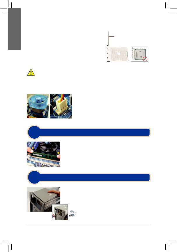
English
B. Installing an AMD CPU (skip this step if the motherboard has a built-in CPU)
B-1 Completely raise the CPU socket lever. Align the CPU pin one (small triangle marking) with the triangle marking on the CPU socket and gently insert the CPU into the socket. Make sure that the CPU pins fit perfectly into their holes.
B-2 Once the CPU is positioned into its socket, place one finger down on the middle of the CPU, lowering the socket lever and latching it into the fully locked position.
•• Do not force the CPU into the CPU socket. The CPU cannot fit in if oriented incorrectly. Adjust the CPU orientation if this occurs.


 •• DO NOT touch socket contacts. To protect the CPU socket, always replace the protective socket cover when the CPU is not installed.
C. Installing the CPU Cooler
C-1 Before installing the CPU cooler, please first add a thin layer of heat sink paste on the surface of the CPU. Then install the cooler (refer to the installation manual for your CPU cooler).
C-2 Connect the CPU cooler cable to the CPU_FAN connector located on the motherboard so that the cooler can properly function to prevent the CPU from overheating.
Step
2 Installing Memory
Note the orientation of the memory module. Spread the retaining clips at both ends of the memory socket. Place the memory module on the socket. As indicated in the  pictureontheleft,placeyourfingersonthetopedgeofthememory,pushdownon the memory and insert it vertically into the memory socket. The clips at both ends of the socket will snap into place when the memory module is securely inserted.
Step
3 Preparing the Case and Installing a Power Supply
UsingtheGIGABYTEdesktopsystemasthedemonstrationexample,pleasefirst remove both sides and the lid of the case in order to install the power supply. Place the power supply in the correct place in the case and secure it with screws. Installation and placement of the power supply may differ depending on the type
of case used.
To ensure sufficient power can be supplied to your system, it is
recommended that a power supply of good quality be used. If a power supply is used that does not provide the required power, the result can lead to an unstable or unbootable system.
— 2 —
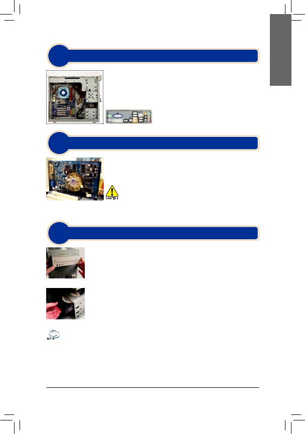
Step
4 Installing the Motherboard
Remove the original I/O shield from the back of the case and replace it with the motherboard I/O shield. Place the motherboard within the case by positioning it into its I/O shield. Align the mounting screw holes on the motherboard with their corresponding mounting holes on the case. Secure the motherboard in place with screws.
I/O Shield
Step
5 Installing an Expansion Card
Locate an expansion slot that supports your card and remove the slot cover from the case back panel. Then insert the expansion card into the slot. Secure the expansion card’s bracket to the case back panel with a screw.
|
•• |
Before purchasing an expansion card, check the length of the card, making |
|
|
sure it can fit into your case. |
||
|
PCI Express Graphics Card |
•• |
Make sure that the expansion card is fully seated in its slot. |
Step
6 Installing IDE and SATA Devices
6-1 Install your optical drives, such as DVD-ROM and CD-ROM drives.
Remove the 5.25″ drive bay cover from the front of the case. Mount the optical drive in the 5.25″ drive bay and secure it with screws.
Installing an Optical Drive
6-2 Install your IDE and SATA hard drives.
Install the hard drive into a drive bay within the case and secure it with screws.
Installing a Hard Drive
•• One motherboard IDE connector can connect up to two IDE devices. Prior to installation, check the jumper
settings (master and slave) on your IDE devices.
•• If more than one hard drive is installed, enter system BIOS Setup to set the hard drive boot sequence.
English
— 3 —
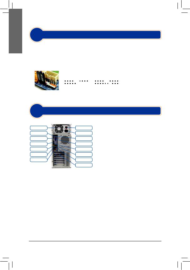
English
Step
7 Connecting Cables to Internal Connectors
7-1 Connect cables to internal connectors and headers on the motherboard, including IDE/SATA connectors, and front panel audio, USB, IEEE 1394 headers, etc.
7-2 Attach the front panel module (differs depending on the case design, consisting of power indicator, hard drive activity indicator, speakers, reset switch, power switch, etc.) from the case to the front panel header (F_PANEL) on the motherboard.
|
Pin Assignments A: |
Pin Assignments B: |
MSG: Message/Power/Sleep LED |
||||||||||||||||||||||||
|
+MSG- +PW- |
+SPEAK- |
+MSG- +PW- |
+SPEAK- |
PWR: Power LED |
||||||||||||||||||||||
|
2 |
20 |
PW: Power Switch |
||||||||||||||||||||||||
|
SPEAK: Speaker |
||||||||||||||||||||||||||
|
1 |
19 |
HD: Hard Drive Activity LED |
||||||||||||||||||||||||
|
RES: Reset Switch |
||||||||||||||||||||||||||
|
+HD |
— -RES+ |
+HD- |
-RES+ -CI+ |
+PWR- |
||||||||||||||||||||||
|
Front Panel Header |
NC |
CI: Chassis Intrusion Header |
||||||||||||||||||||||||
|
(Note) |
The pin assignments for the front panel header may differ by model. Refer |
|||||||||||||||||||||||||
|
to the motherboard user’s manual for the actual pin assignments. |
Step
8 Connecting Peripherals
Back Panel of the Case
|
Power Supply |
Power Switch |
|
PS/2 Keyboard Port |
PowerCordConnector |
|
DVI-D Port |
PS/2 Mouse Port |
|
HDMI Port |
D-Sub Port |
|
eSATA Port |
S/PDIF Connector |
|
IEEE 1394 Port |
USB Ports |
|
Audio Jacks |
RJ-45 LAN Port |
|
ExternalGraphics Card |
Once the steps above have been completed, connect the peripheral devices to the computer, such as the keyboard, mouse, monitor, etc. Then connect the power, turn on the system, and install all required software.
— 4 —
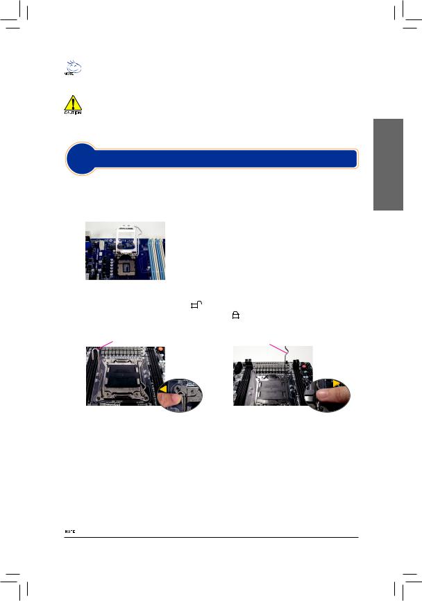
•• Die Installationsreihenfolge kann je nach Typ des verwendeten Gehäuses sowie der verwendeten Geräte variieren. Die folgenden Installationsanweisungen betreffen Desktop-Systeme von GIGABYTE und dienen nur als Referenz.
•• Schlagen Sie bitte ausführliche technische Daten des Motherboards im beigelegten Benutzerhandbuch nach.
•• Stellen Sie vor der Installation von Geräten sicher, dass Ihre Geräte mit den Anschlüssen Ihres Computers kompatibel sind.
•• Schalten Sie immer vor dem Installieren die Geräte und Ihren Computer aus. Trennen Sie den Rechner vom
Stromnetz, um Schäden an den Geräten und den Systemkomponenten zu vermeiden.
•• Stellen Sie das Computersystem auf eine stabile Unterlage, damit die Installation nicht durch Wackeln beeinträchtigt wird.
Schritt
1 Installieren einer CPU und eines CPU-Kühlers
A.Installieren einer Intel CPU (überspringen Sie diesen Schritt, wenn das Motherboard über einen eingebauten Prozessor verfügt)
A-1 Beachten Sie die folgenden Anweisungen basierend auf Ihren CPU-Spezifikationen:
•• Typ A:
|
Heben Sie den CPU-Sockelhebel an, dadurch hebt sich auch die |
|||||||||
|
Metallladeplatte. |
|||||||||
|
a. Falls die Sockelschutzabdeckung am CPU-Sockel befestigt ist, |
|||||||||
|
entfernen Sie sie zunächst. |
|||||||||
|
b. Falls die schützende Sockelabdeckung an der Metallandruckplatte |
|||||||||
|
befestigt ist, nehmen Sie sie jetzt noch nicht ab. Die Sockelabdeckung |
|||||||||
|
kann sich beim Wiederanziehen des Hebels nach Einsetzen der CPU |
|||||||||
|
•• |
von selbst lösen. |
||||||||
|
Typ B: |
|||||||||
|
Drücken Sie Hebel A (der Markierung „ |
” am nächsten) nach unten und vom Sockel weg, um ihn |
||||||||
|
zu lösen. Drücken Sie dann Hebel B (der Markierung „ |
” am nächsten) nach unten und vom Sockel |
||||||||
|
weg und heben Sie ihn an. Drücken Sie behutsam Hebel |
A, um den Deckrahmen anzuheben. Öffnen |
||||||||
|
Sie den Deckrahmen. |
|||||||||
|
Hebel A |
Hebel B |
||||||||
A-2 Halten Sie die CPU mit Daumen und Zeigefinger. Richten Sie die (Dreieck-) Markierungen für Pin 1 auf der CPU und die Pin 1-Ecke des CPU-Sockels aufeinander aus. (Sie können ebenfalls die CPU-Kerben auf die Ausrichtungsnasen des Sockels ausrichten.) Legen Sie dann vorsichtig die CPU in der richtigen Position ein.
A-3 Legen Sie den Schutzrahmen wieder auf und stellen den CPU-Sockelhebel in seine Arretierposition zurück, sobald die CPU richtig sitzt.
Bringen Sie den Deckrahmen nach dem ordnungsgemäßen Einsetzen der typ B vorsichtig wieder an. Sichern Sie anschließend Hebel B unter dessen Befestigungsnase. Die Sockelabdeckung kann sich beim Betätigen des Hebels vom Deckrahmen lösen. Sichern Sie zuletzt Hebel A unter dessen Befestigungsnase, um die Installation der CPU abzuschließen.
 Detaillierte Anweisungen zur CPU-Installation entnehmen Sie bitte der Bedienungsanleitung.
— 1 —
Deutsch
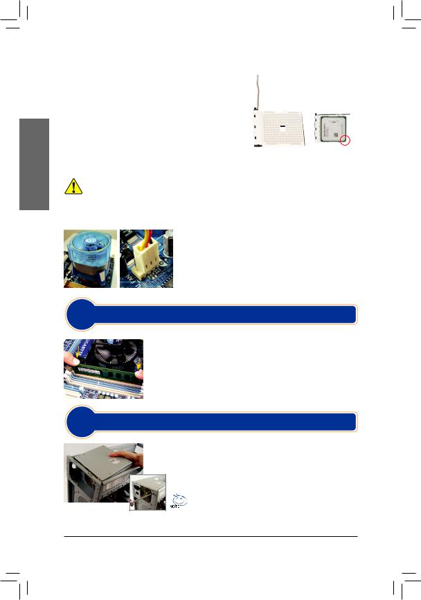
Deutsch
B.Installieren einer AMD CPU (überspringen Sie diesen Schritt, wenn das Motherboard über einen eingebauten Prozessor verfügt)
|
B-1 Ziehen Sie den CPU-Sockelhebel ganz nach oben. |
CPU-Sockel-hebel |
||||
|
Richten Sie den Pin 1 der CPU (mit einem kleinen Dreieck |
|||||
|
gekennzeichnet) auf die Dreieck-Markierung am CPU-Sockel |
|||||
|
aus und legen Sie dann vorsichtig die CPU ein. Stellen Sie |
|||||
|
sicher, dass die Pins der CPU perfekt in die Öffnungen |
|||||
|
passen. |
|||||
|
B-2 Wenn die CPU richtig in dem Sockel sitzt, legen Sie bitte einen |
|||||
|
CPU-Sockel |
Pin 1 |
||||
|
Finger auf die Mitte der CPU, drücken den Sockelhebel nach |
|||||
|
unten und bringen ihn in seine Arretierposition zurück. |
•• Stecken Sie die CPU nicht mit Gewalt in den CPU-Sockel. Die CPU lässt sich nicht einpassen, wenn die
Ausrichtung falsch ist. Ändern Sie in diesem Fall die Ausrichtung der CPU.


 •• Berühren Sie NICHT die Sockelkontakte. Setzen Sie die Schutzabdeckung grundsätzlich wieder auf, wenn keine CPU installiert ist. Dies schützt den Sockel vor Beschädigungen.
C. Installieren des CPU-Kühlers
C-1 Bevor Sie den CPU-Kühler installieren, tragen Sie bitte gleichmäßig eine Schicht Wärmeleitpaste auf die Oberfläche der CPU auf. Installieren Sie anschließend den Kühler (siehe Installationsanleitung Ihres CPU-Kühlers).
C-2 Verbinden Sie das Kabel des CPU-Kühlers mit dem Anschluss CPU_FAN auf dem Motherboard, damit der Kühler richtig arbeitet und die CPU vor Überhitzung schützt.
Schritt2
Installieren eines Arbeitsspeichermoduls
Achten Sie auf die korrekte Ausrichtung des Speichermoduls. Drücken Sie die Haltebügel an beiden Enden des Speichersteckplatzes nach außen. Stecken Sie das Speichermodul in den Steckplatz ein. Legen Sie wie links abgebildet Ihre Finger auf die obere Kante des Speichermoduls und drücken das Modul nach unten, damit es senkrecht im Speichersteckplatz sitzt. Die Haltebügel an beiden Enden des Steckplatzes rasten ein, wenn das Speichermodul richtig eingesteckt wurde.
Schritt
3 Einrichten des Gehäuses/ Installieren des Netzteils
Entfernen Sie bitte wie am Beispiel des GIGABYTE Desktop-Systems zuerst die beiden seitlichen Abdeckungen und den oberen Deckel vom Gehäuse, um das Netzteil zu installieren. Installieren Sie das Netzteil an der passenden
Stelle im Gehäuse, fixieren Sie es mit Schrauben.Platzierung des
Netzteils kann je nach Typ des verwendeten Gehäuses variieren.
Damit Ihr System ausreichend Strom erhält, sollten Sie unbedingt ein hochwertiges Netzteil einsetzen. Wenn Sie ein Netzteil verwenden, das den notwendigen Strom nicht liefern kann, wird das System instabil oder lässt sich nicht starten.
— 2 —
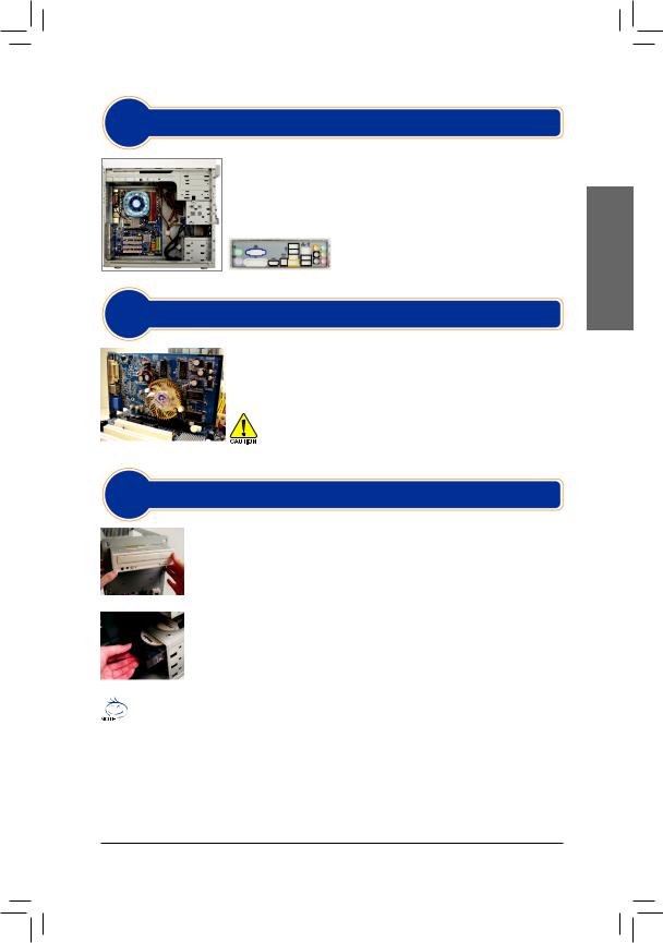
Schritt
4 Installieren des Motherboards
Entfernen Sie die ursprüngliche E/A-Blende von der Rückseite des Gehäuses und ersetzen Sie sie durch die dem Motherboard beigelegte E/A-Blende. Legen Sie das Motherboard in das Gehäuse ein, wobei die E/A-Anschlüsse auf die E/A-Blende ausgerichtet werden müssen. Richten Sie die Schraubenlöcher am Motherboard auf die entsprechenden Befestigungslöcher am Gehäuse aus. Befestigen Sie das
Motherboard mit Schrauben am Gehäuse.
I/O-Blende
Schritt
5 Installieren einer Erweitungskarte
Wählen Sie einen Steckplatz, der Ihre Karte unterstützt. Entfernen Sie die entsprechende Steckplatzblende an der Rückseite des Gehäuses. Stecken Sie dann die Erweiterungskarte in den Steckplatz ein. Fixieren Sie den Bügel der
Karte mit einer Schraube an der Gehäuserückwand.
|
•• |
Informieren Sie sich vor dem Kauf über die Länge der Karte; überzeu- |
|
|
gen Sie sich davon, dass sie in das Gehäuse passt. |
||
|
PCI Express Grafikkarte |
•• |
Stellen Sie sicher, dass die Erweiterungskarte richtig im Steckplatz sitzt. |
Schritt
6 Installieren der IDEund SATA-Geräte
6-1 Installieren Sie Ihre optischen Laufwerke wie z.B. DVDoder CD-Laufwerke. Entfernen Sie die Blende des 5,25”-Laufwerkfachs von der Frontseite des Gehäuses. Legen Sie das optische Laufwerk in das 5,25” Laufwerkfach ein und befestigen es mit Schrauben.
Installieren eines optischen Laufwerks
6-2 Installieren Sie Ihre IDEund SATA-Festplatten.
Legen Sie die Festplatte in ein Laufwerkfach innerhalb des Gehäuses ein und befestigen Sie sie mit Schrauben.
Installieren einer Festplatte
•• Mit einem IDE-Anschluss am Motherboard können zwei IDE-Geräte verbunden werden. Prüfen Sie bitte
vor der Installation die Jumpereinstellungen (Master und Slave) an Ihren IDE-Geräten.
•• Wenn mehr als eine Festplatte installiert ist, rufen Sie bitte das System-BIOS-Einstellungsprogramm auf und stellen die Bootreihenfolge der Festplatten ein.
Deutsch
— 3 —
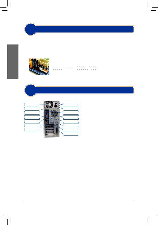
Deutsch
Schritt
7 Verbinden der Kabel mit den internen Anschlüssen
7-1 Verbinden Sie Kabel mit den entsprechenden Anschlüssen und Sockel am Motherboard inklusive IDE/ SATA-Anschlüsse, Front-Audio, USB, IEEE 1394 usw.
7-2 Verbinden Sie das Front Panel-Modul (es besteht je nach Gehäusedesign aus einer Strom-LED, einer
Festplattenaktivitäts-LED, einem Lautsprecher, einem Reset-Schalter, einem Stromschalter usw.) am
Gehäuse mit dem Front Panel-Anschluss (F_PANEL) am Motherboard.
|
Pinbelegung A: |
Pinbelegung B: |
MSG: Meldung-/Betrieb-/Ruhezustand-LED |
||||||||||||||||||||||
|
+MSG- +PW- |
+SPEAK- |
+MSG- +PW- |
+SPEAK- |
PWR: Betriebsanzeige-LED |
||||||||||||||||||||
|
PW: Stromschalter |
||||||||||||||||||||||||
|
2 |
20 |
SPEAK: Lautsprecher |
||||||||||||||||||||||
|
1 |
19 |
HD: Festplattenaktivitäts-LED |
||||||||||||||||||||||
|
RES: Reset-Schalter |
||||||||||||||||||||||||
|
+HD- -RES+ |
+HD- -RES+ -CI+ |
+PWR- |
CI: Gehäuse offen-Anschluss |
|||||||||||||||||||||
|
Front Panel-Anschluss |
NC |
|||||||||||||||||||||||
Hinweis: Die Pinbelegung der Frontblendenanschlüsse kann je nach Modell abweichen. Bitte entnehmen Sie die tatsächliche Pinbelegung der jeweiligen Motherboard-Bedienungsanleitung.
Schritt
8 Verbinden der Peripheriegeräte
|
Gehäuserückwand |
|
|
Netzteil |
Netzschalter |
|
PS/2-Tastaturanschluss |
Netzkabelanschluss |
|
DVI-D-Port |
PS/2-Mausanschluss |
|
HDMI-Port |
D-Sub-Anschluss |
|
eSATA-Ports |
S/PDIF-Anschluss |
|
IEEE1394-Port |
USB-Ports |
|
Audioanschlüsse |
RJ-45 LAN-Port |
|
Externe Grafikkarte |
Nachdem die obigen Schritte ausgeführt wurden, schließen Sie bitte die Peripheriegeräte wie z.B. Tastatur, Maus, Monitor usw. an den Computer an. Schließen Sie abschließend den Computer an das Stromnetz an, schalten das System ein und installieren Sie benötigte Software.
— 4 —
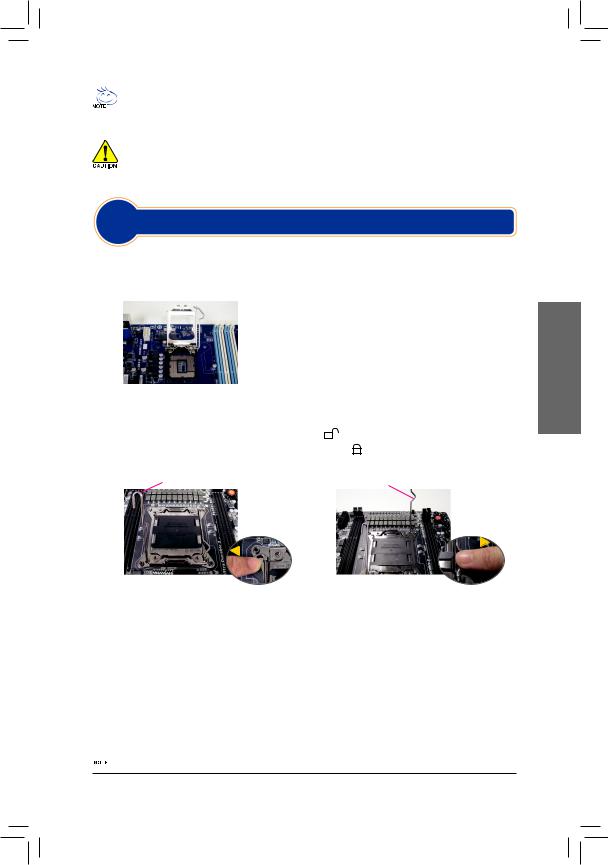
•• El proceso de instalación puede variar dependiendo del tipo de CAJA y dispositivos utilizados. Las
instrucciones de instalación que aparecen a continuación son de aplicación para ordenadores de escritorio GIGABYTE y sólo a modo de referencia.
•• Consulte el manual de usuario incluido para obtener especificaciones detalladas sobre la placa madre.
•• Antes de instalar los dispositivos, asegúrese de que sean compatibles con los conectores del ordenador.
•• Antes de instalar los dispositivos, asegúrese de apagar los dispositivos y el ordenador. Desconecte el cable
de alimentación de la toma de corriente para evitar dañar los dispositivos y los componentes del sistema.
•• Coloque la ordenador sobre una superficie estable para evitar que movimientos bruscos causen una instalación incorrecta.
|
Paso |
|
|
1 |
Instalación del procesador y del ventilador del procesador |
A. Instalación de un procesador Intel (omita este paso si la placa base tiene una CPU integrada)
A-1 Consulte las siguientes instrucciones basadas en las especificaciones de la CPU:
•• Tipo A:
|
Levante completamente la palanca del zócalo de la CPU y la placa |
|||||||||
|
metálica de carga también se levantará. |
|||||||||
|
a. Si la tapa del zócalo de protección está sujeta al zócalo de la CPU, |
|||||||||
|
quítela primero. |
|||||||||
|
b. Si la tapa protectora del zócalo está sujeta a la placa de carga |
|||||||||
|
metálica, no la quite en este momento. La tapa del zócalo puede |
|||||||||
|
desprenderse de la placa de carga automáticamente durante el |
|||||||||
|
•• |
proceso de reengarce de la palanca después de insertar la CPU. |
||||||||
|
Tipo B: |
|||||||||
|
Presione la palanca A (la más cercana a la marca « |
«) hacia abajo desplazándola del zócalo para |
||||||||
|
liberarla. Presione la palanca B (la más cercana a la marca « |
«) hacia abajo desplazándola del zócalo |
||||||||
|
y levántela. Presione suavemente la palanca A para levantar la chapa metálica. Levante la chapa. |
|||||||||
|
La palanca A |
La palanca B |
||||||||
A-2 Sostenga el procesador con los dedos pulgar e índice. Alinee la marca de la clavija 1 del procesador (triángulo) con la esquina de la clavija 1 del socket del procesador (o puede alinear las muescas del procesador con las muescas de alineación del socket) e inserte con cuidado el procesador.
A-3 Una vez que el procesador se encuentre insertado de forma correcta, vuelva a instalar la cubierta de protección y baje la palanca del socket del procesador y colóquela en la posición de bloqueo.
Cuando la tipo B esté correctamente insertada, vuelva a colocar con cuidado la placa metálica. A continuación, asegure la palanca B debajo de su lengüeta de retención. La chapa del zócalo podría desprenderse durante el proceso de sujeción de la palanca. Finalmente, asegure la palanca A debajo de su lengüeta de sujeción para completar la instalación de la CPU.
 Para obtener instrucciones detalladas sobre cómo instalar la CPU, consulte el manual del usuario.
— 1 —
Español

Español
B. Instalación del procesador AMD (omita este paso si la placa base tiene una CPU integrada)
B-1 Levante por completo la palanca del socket del procesador. Alinee la clavija 1 del procesador (marca con un triángulo pequeño) con la marca con un triángulo en el socket del procesador e inserte con cuidado el procesador en el socket.
Asegúresedequelasclavijasdelprocesadorencajenenforma correcta en los orificios.
B-2 Una vez que el procesador se encuentre insertado dentro del socket, presione hacia abajo con un dedo en el medio del procesador y baje la palanca del socket del procesador y colóquela en la posición de bloqueo.
Palanca del socket del procesador
|
Socket del procesador |
Clavija 1 |
•• No utilice la fuerza para insertar el procesador en el socket del procesador. El procesador no encajará si se encuentra orientado en forma incorrecta. S Si éste fuera el caso, reajuste la orientación del procesador.
•• NO toque los contactos del zócalo. Para proteger el zócalo del procesador, vuelva a colocar siempre la cubierta protectora del zócalo luego de la instalación del procesador
C. Instalación del ventilador del procesador
C-1 Antes de instalar el ventilador del procesador, coloque primero una capa fina de pasta disipadora de calor sobre la superficie del procesador. Luego, instale el ventilador (consulte el manual de instalación del ventilador del procesador).
C-2 Conecte el cable del ventilador del procesador al conector
“CPU_FAN”ubicadoenlaplacamadreafindequeelventilador pueda funcionar de forma correcta y evitar que ocurra un recalentamiento del procesador.
Paso
2 Instalación De Los Módulos De Memorias
Observe la orientación del módulo de memoria. Abra las piezas de sujeción de plástico ubicadas en ambos lados de la ranura de memoria. Coloque el módulo de memoria en la ranura. Como se indica en la imagen ubicada a la izquierda, coloque los dedos sobre el borde superior de la memoria, presione hacia abajo la memoria e insértela verticalmente en la ranura de memoria. Las piezas de sujeción de plástico quedarán encajadas en su lugar y sujetando al modulo de memoria cuando éste se encuentre colocado de forma correcta.
Paso
3 Preparación de la caja e instalación de la fuente de alimentación
Utilizando la caja GIGABYTE como ejemplo, retire los paneles laterales y la tapa de la caja con el fin de instalar la fuente de alimentación. Coloque la fuente de alimentación en el lugar correcto del gabinete y asegúrela con tornillos. La instalaciónycolocacióndelafuentedealimentaciónpuedevariarsegún
el tipo de caja utilizada.
Para asegurar que se suministre al sistema la cantidad de energía adecuada, se recomienda la utilización de una fuente de alimentación de buena calidad. Si se utiliza una fuente de alimentación que no proporciona la energía necesaria, el resultado podría ser un sistema inestable o que no pueda ser iniciado.
— 2 —
![]()
Paso
4 Instalación De La Placa Madre
Extraiga el panel de protección de las I/O (entradas/salidas) original ubicada en la parte trasera de la caja y reemplácela por el panel de conexiones de la placa madre. Coloque la placa madre dentro de la caja encajándola con el hueco descubierto I/O (de entradas y salidas). Alinee los orificios de los tornillos de soporte de la placa madre con los orificios de soporte de la caja.
Sujete la placa madre en su lugar con tornillos.
Protector de E/S
Paso
5 Instalación De Una Tarjeta De Expansión
Busque una ranura de expansión que sea compatible con la tarjeta y retire la tapa de la ranura ubicada en el panel trasero de la caja. Luego, inserte la tarjeta de expansión en la ranura. Asegure el soporte de la tarjeta de expansión al panel trasero del de la caja utilizando un tornillo.
•• Antes de adquirir una tarjeta de expansión, verifique la longitud de la tarjeta para asegurarse de que pueda ser colocada en el la caja.
|
Tarjeta gráfica PCI Express |
•• Asegúrese de que la tarjeta de expansión quede insertada por completo |
|
|
en la ranura. |
||
Paso
6 Instalación De Los Dispositivos IDE Y SATA
6-1 Instale sus unidades ópticas, como unidades de DVD-ROM y CD-ROM. Extraiga la tapa frontal para unidades de 5,25” ubicada en la parte delantera de la caja. Instale la unidad óptica en el espacio para unidades de 5,25” y sujétela con tornillos.
Instalación de una unidad óptica
6-2 Instale sus unidades de discos duros IDE y SATA.
Instale la unidad de disco duro en el espacio para unidades de disco duro ubicada dentro de la caja y asegúrela con tornillos.
Instalación de una unidad de disco duro
•• Se puede conectar hasta dos dispositivos IDE en un conector IDE de la placa madre. Antes de realizar la
instalación, compruebe la configuración de los jumpers (principal y secundario) de los dispositivos IDE.
•• Si se instala más de un disco duro, acceda al BIOS Setup (Configuración del BIOS) del sistema para establecer la secuencia de inicio de los discos duros.
Español
— 3 —
Español
Paso
7 Conexión De Los Cables A Los Conectores Internos
7-1 Conecte los cables en los conectores y conexiones internas de la placa madre, incluidos los conectores IDE/SATA, audio del panel frontal, USB, IEEE 1394, etc.
7-2 Conecte el módulo del panel frontal (diferente según el diseño de la caja y compuesto por un indicador de encendido, indicador de actividad de disco duro, altavoces, interruptor de reinicio, interruptor de encendido/apagado, etc.) de la caja a la conexión (F_PANEL) ubicada en la placa madre.
|
Asignaciones de clavijas A: |
Asignaciones de clavijas B: |
MSG: LED de mensajes/encendido/ |
|||||||||||||||||||||||
|
suspensión |
|||||||||||||||||||||||||
|
+MSG- +PW- |
+SPEAK- |
+MSG- +PW- |
+SPEAK- |
PWR: LED de encendido |
|||||||||||||||||||||
|
2 |
20 |
PW: Interruptor de encendido/apagado |
|||||||||||||||||||||||
|
SPEAK: Altavoces |
|||||||||||||||||||||||||
|
1 |
19 |
HD: LED de actividad de disco duro |
|||||||||||||||||||||||
|
RES: Interruptor de reinicio |
|||||||||||||||||||||||||
|
+HD- -RES+ |
+HD- -RES+ -CI+ |
+PWR- |
|||||||||||||||||||||||
|
CI: Header de intrusión al chasis |
|||||||||||||||||||||||||
|
NC |
Cabecera del panel frontal (Nota) Las asignaciones de clavijas para el header del panel frontal pueden ser distintas según el modelo. Consulte el manual de usuario de la placa base para obtener información sobre las asignaciones de clavijas actuales.
Paso
8 Conexión de periféricos
Panel trasero del gabinete
|
Fuente de alimentación |
Interruptor de |
|
encendido/apagado |
|
|
Puerto de teclado PS/2 |
Conector del cable de |
|
alimentación |
|
|
Puerto DVI-D |
Puerto del ratón PS/2 |
|
Puerto HDMI |
Puerto D-Sub |
|
Puertos eSATA |
Conector S/PDIF |
|
Puerto IEE1394 |
Puertos USB |
|
Conectores de audio |
Puerto de red RJ-45 |
|
Tarjeta gráfica externa |
Una vez que se hayan completado estos pasos, conecte los dispositivos periféricos al ordenador, dispositivos como el teclado, el ratón, el monitor, etc. Luego, conecte la alimentación, encienda el sistema e instale todo el software necesario.
— 4 —
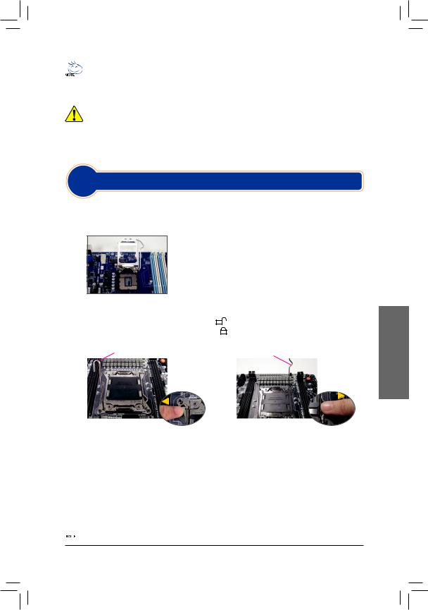
•• A sequência pela qual a instalação é feita pode variar conforme o tipo de caixa e os dispositivos
usados. As instruções de instalação embaixo aplicam-se aos sistemas desktop da GIGABYTE e servem apenas como referência.
•• Consulte o manual do utilizador incluído juntamente com a placa principal para obter as especificações desta.
•• Antes de instalar os dispositivos, certifique-se de que estes são compatíveis com os conectores existentes no seu computador.


 •• Antes de instalar os dispositivos, certifique-se de que os dispositivos estão desligados no seu computador. Retire o cabo de alimentação da tomada elétrica para evitar danos ao dispositivos e os componentes do sistema.
•• Coloque o computador sobre uma superfície estável para evitar uma instalação incorrecta devido a instabilidade do mesmo.
Etapa
1 Instalação da CPU e do dissipador de calor
A. Instalação de uma CPU Intel (avance este passo se a placa principal possuir uma CPU incorporada)
A-1 Consulte as seguintes instruções de acordo com as especificações da CPU:
•• Tipo A:
Levante a alavanca do socket da CPU e a placa de carregamento em metal irá também levantar.
a.Se a tampa de protecção do socket estiver aparafusada ao socket da CPU, remova-a primeiro.
b.Se a tampa de protecção do socket estiver aparafusada à placa de carregamentometálica,nãoaremovanestafase.Atampadosocket poderá saltar automaticamente da placa de carregamento ao accionar a alavanca após a inserção da CPU.
|
•• Tipo B: |
|||||||||
|
PressioneaalavancaA(maispróximadamarca» |
«)eafaste-adosoqueteparadestravar.Emseguida |
||||||||
|
pressione a alavanca B (mais próxima da marca « |
«) e afaste-a do soquete para destravar. Pressione |
||||||||
|
ligeiramente a alavanca A para poder levantar a placa de contenção. Abra a placa de contenção. |
|||||||||
|
A alavanca A |
A alavanca B |
||||||||
A-2 Segure na CPU com o polegar e o dedo indicador. Alinhe o pino 1 da CPU (marca de triângulo) com o cantodosocket(oupodealinharosentalhesexistentesnaCPUcomaschavesdealinhamentoexistentes no respectivo socket) e posicione cuidadosamente a CPU na posição correta.
A-3 Quando a CPU estiver devidamente instalada, reponha a placa de carga e empurre a alavanca do socket da CPU para que esta retome a sua posição original.
Após inserir corretamente a tipo B, volte a fechar cuidadosamente a placa de contenção. Em seguida, fixe a alavanca B abaixo da aba de retenção. A tampa do socket poderá saltar da placa de carregamento ao acionaraalavanca.Porfim,fixeaalavancaAdebaixodaabaderetençãoparaconcluirainstalaçãodaCPU.
 Consulte o manual do utilizador para obter instruções detalhadas acerca da instalação da CPU.
— 1 —
Português
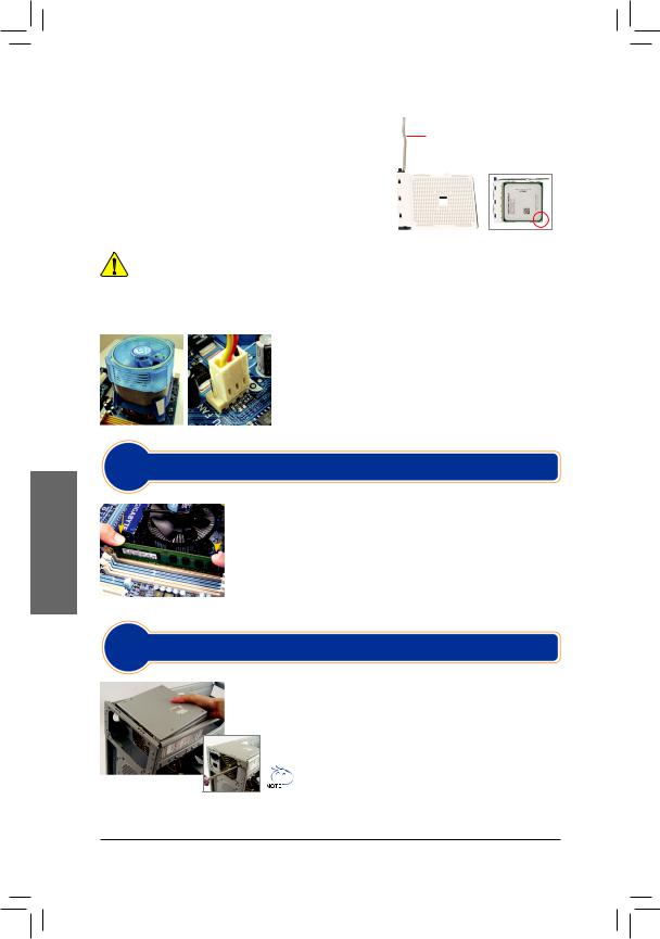
Português
B. Instalação de uma CPU AMD (avance este passo se a placa principal possuir uma CPU incorporada)
B-1 Levante completamente a alavanca do socket da CPU. Alinhe o pino 1 da CPU (marca de triângulo) com a marca de triângulo existente no socket da CPU e posicione cuidadosamente a CPU no socket. Certifique-se de que os pinosdaCPUficambemencaixadosnosrespectivosorifícios.
B-2 QuandoaCPUestivercolocadanorespectivosocket,coloque umdedosobreapartecentraldaCPUaomesmotempoque baixaaalavancadosocketeafixadeformaaestaficarpresa.
Alavanca do socket da CPU
•• Não force a entrada da CPU no respectivo socket. Se a CPU não estiver posicionada na direção certa não será possível instalá-la. Ajuste a posição da CPU se tal acontecer.


 •• NÃO TOQUE nos contatos do socket. Para proteger o socket da CPU, reponha sempre a capa protetora quando a CPU não estiver instalada.
C. Instalação do dissipador de calor da CPU
C-1 Antes de instalar o dissipador de calor da CPU, adicione uma fina camadademassatérmicasobreasuperfíciedaCPU.Instaledepois odissipadordecalor(consulteomanualdeinstalaçãododissipador de calor da sua CPU).
C-2 LigueocabododissipadordecalordaCPUaoconectorCPU_FAN existente na placa principal de forma a que este possa funcionar corretamente para evitar o sobreaquecimento da CPU.
Etapa2
Instalação Da Memória
Tenhaematençãoaorientaçãodomódulodememória.Abraaspatilhasexistentes emambasasextremidadesdosocketdomódulodememória.Coloqueomódulo  de memória no socket. Tal como mostrado na imagem à esquerda, coloque os dedos sobre a extremidade superior do módulo de memória e exerça pressão para baixo para introduzir o módulo no socket na vertical.As patilhas existentes em ambas as extremidades do socket retomam a sua posição original emitindo
um estalido quando o módulo de memória estiver devidamente encaixado.
Etapa
3 Preparação da caixa e instalação da fonte de alimentação
Tendo como referência o sistema desktop da GIGABYTE, comece por remover ambos os painéis laterais e a parte superior da caixa para poder instalar a fonte de alimentação. Introduza a fonte de alimentação no local correcto no chassis e fixe-a com a ajuda de parafusos.A instalação e a posição da fonte de
alimentação pode variar conforme o tipo de caixa utilizada.
Para assegurar a alimentação do sistema, recomendamos-lhe que  use uma fonte de alimentação de boa qualidade. Se utilizar uma fonte de alimentação que não tenha capacidade para fornecer a alimentação suficiente, o sistema pode ficar instável ou não conseguir iniciar-lo
— 2 —
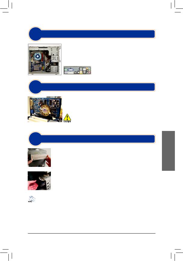
Etapa
4 Instalação Da Placa Principal
Remova o espelho I/O original a partir da parte detrás da caixa e substitua-o pelo espelho I/O da placa principal. Instale a placa principal no interior da caixa posicionando-a no respectivo espelho I/O. Alinhe os orifícios para parafusos existentes na placa principal com os orifícios correspondentes existentes na caixa. Fixe a placa principal no devido lugar com parafusos.
Espelho I/O
Etapa
5 Instalação Da Placa De Expansão
Procure uma ranhura de expansão que suporte a placa e remova a cobertura da ranhura a partir do painel traseiro da caixa. Depois, introduza a placa de expansão na ranhura. Utilize um parafuso para fixar devidamente o suporte da
placa de expansão ao painel traseiro da caixa.
|
•• |
Antes de comprar uma placa de expansão, verifique o comprimento da |
|
|
placa para ter a certeza de que esta cabe na caixa. |
||
|
Placa gráfica PCI Express |
•• |
Certifique-se de que a placa de expansão está totalmente introduzida na |
|
ranhura. |
Etapa
6 Instalação De Dispositivos IDE E SATA
6-1 Instale as suas unidades ópticas como, por exemplo, unidade de DVD-ROM e CDROM. Remova a tampa do compartimento da unidade de 5,25” a partir da parte da frente da caixa. Instale a unidade óptica no compartimento de 5,25” e fixe-a com parafusos.
IInstalação de uma unidade óptica
6-2 Instale as unidades de disco rígido IDE e SATA.
Introduza a unidade de disco rígido num dos compartimentos disponíveis e fixe-a com a ajuda de parafusos.
Instalação de uma unidade de disco rígido
•• Um conector IDE da placa principal permite a ligação de um máximo de dois dis positivos IDE. Antes da
instalação, verifique as definições dos jumpers (principal e secundário) do seus dispositivos IDE.
•• Se tiver mais do que uma unidade de disco rígido instalada, entre na página de configuração do BIOS para definir a sequência de arranque das unidades de disco rígido.
Português
— 3 —
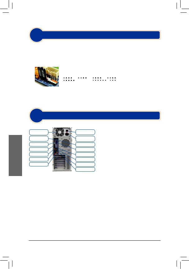
Português
Etapa
7 Ligação Dos Cabos Aos Conectores Internos
7-1 Ligue os cabos aos conectores internos e aos conectores existentes na placa principal incluindo os conectores IDE/SATA, o conector de áudio do painel frontal, o conector USB, os conectores IEEE 1394, etc.
7-2 Ligue o módulo do painel frontal (varia conforme o design da caixa e pode incluir um LED indicador de alimentação, de atividade da unidade de disco rígido, altofalantes, botão de reposição do sistema,
comutador de alimentação, etc.) da caixa ao conector respectivo (F_PANEL) existente na placa principal.
|
Distribuição dos pinos A: |
Distribuição dos pinos B: |
MSG: mensagem/energia/suspensão |
||||||||||||||||||||||
|
+MSG |
— |
+PW |
— |
+SPEAK- |
+MSG- +PW- |
+SPEAK- |
em LED |
|||||||||||||||||
|
PWR: Energia em LED |
||||||||||||||||||||||||
|
2 |
20 |
PW: Comutação de Energia |
||||||||||||||||||||||
|
1 |
19 |
SPEAK: Altofalante |
||||||||||||||||||||||
|
HD: Atividade da unidade do disco |
||||||||||||||||||||||||
|
rígido em LED |
||||||||||||||||||||||||
|
Conector do painel frontal |
+HD |
— -RES+ |
+HD- |
-RES+ -CI+ |
+PWR- |
|||||||||||||||||||
|
NC |
RES: Comutador de reposição |
CI: Conector de detecção de intrusão no chassis
(Nota) A distribuição dos pinos do conector do panel frontal pode variar conforme o modelo. Consulte o manual do utilizador incluído juntamente com a placa principal para mais informações sobre a distribuição dos pinos.
Etapa
8 Ligação Dos Periféricos
Painel traseiro da caixa
|
Fonte de |
Comutador de |
|
alimentação |
alimentação |
|
Porta para teclado |
Conector do cabo de |
|
PS/2 |
alimentação |
|
Porta DVI-D |
Porta para rato PS/2 |
|
Porta HDMI |
Porta D-Sub |
|
Portas eSATA |
Conector S/PDIF |
|
Porta IEEE1394 |
Portas USB |
|
Tomadas de áudio |
Porta LAN RJ-45 |
|
Placa gráfica externa |
Quando tiver concluído as etapas acima, ligue os periféricos ao computador como, por exemplo, o teclado, o mouse, o monitor, etc. Depois, ligue a alimentação,procedaaoarranquedosistemaeinstale todo o software necessário.
— 4 —
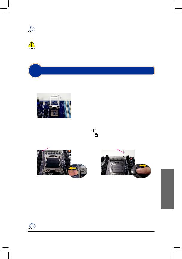
•• La séquence d’installation peut différer selon le type de boitier et de matériels utilisés.
Les instructions d’installation ci-dessous s’appliquent aux systèmes de bureaux GIGABYTE et servent uniquement de référence.
•• Consultez le guide d’utilisation inclus pour des spécifications détaillées de la carte mère.
•• Avant d’installer les composants, assurez vous que votre matériel est compatible avec les connecteurs de votre ordinateur.
•• Avant d’installer les appareils, assurez-vous d’éteindre les appareils et votre ordinateur. Débranchez
|
le cordon d’alimentation de la prise de courant pour éviter d’endommager les appareils et les |
|
|
•• |
composants du système. |
|
Placez l’ordinateur sur une surface stable pour éviter qu’il ne soit secoué suite à une installation |
|
|
inappropriée. |
|
|
Etape |
|
|
1 |
Installation Du Processeur Et Ventilateur Du Processeur |
A. Installation d’un processeur Intel (sautez cette étape si la carte mère comprend un CPU intégré)
A-1 Reportez-vous aux instructions suivantes en fonction des caractéristiques de votre CPU :
•• Type A:
|
Soulevez le levier du socket CPU et la plaque de pression métallique |
||||
|
se lève également. |
||||
|
a. Si le cache de protection du socket est fixé sur le socket CPU, |
||||
|
retirez-le d’abord. |
||||
|
b. Silecouvercledeprotectiondusocketestfixésurlaplaquemétallique |
||||
|
de pression, ne le retirez pas pour l’instant. Le couvercle de la prise |
||||
|
peut sortir automatiquement de la plaque de chargement pendant |
||||
|
•• Type B: |
le processus de ré-engagement du levier après l’insertion du CPU. |
|||
|
Poussez le levier A (le plus près du symbole « |
») vers le bas et l’extérieur du socket pour l’ouvrir. |
|||
|
Puis poussez le levier B (le plus près du symbole « |
») vers le bas et l’extérieur du socket et soulevez- |
|||
le. Appuyez doucement sur le levier A pour permettre à la plaque de maintient de monter. Ouvrez la plaque de maintient.
Le levier A Le levier B
A-2 Tenez le processeur entre votre pouce et votre index. Alignez la marque (triangle) de la broche un du processeur avec le coin de la broche un de la prise du processeur (ou bien alignez les encoches du processeur avec les clés d’alignement de la prise) et insérez doucement le processeur en place.
A-3 Une fois que le processeur est correctement inséré, remplacez la plaque de charge et repoussez le levier dans la position de blocage.
Une fois que le type B a été installé correctement, remettez la plaque de maintient en faisant attention. Puis remettez le levier B en position. Le couvercle du socket sera enlevé de la plaque de maintient pendant le processus d’engagement du levier. Enfin, remettez le levierAen position initiale pour terminer l’installation du CPU.
Pour des instructions détaillées sur l’installation du CPU, veuillez vous référer au manuel d’utilisation.
— 1 —
Français
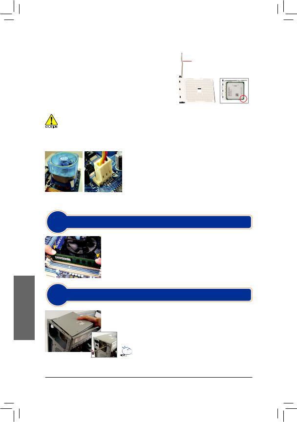
Français
B. Installation d’un processeurAMD (sautez cette étape si la carte mère comprend un CPU intégré)
B-1 Montez à fond le levier le levier du support processeur. Alignez la broche un du processeur (petit triangle) avec le triangle situé sur la prise du processeur et insérez doucement le processeur. Assurez-vous que les broches du processeurs’adaptent parfaitement dans leurs trous.
B-2 Une fois que le processeur est positionné, placez un doigt sur le milieu du processeur, en baissant le levier du support et en le verrouillant dans la position de blocage.
Levier du support processeur
•• Ne faites pas entrer le processeur dans la prise du processeur en forçant. Le processeur ne s’adaptera pas s’il n’est pas orienté correctement. Réglez l’orientation du processeur si cela se produit.
•• NE touchez PAS les contacts de la prise ; pour protéger la prise du processeur, replacez toujours le couvercle de protection de la prise lorsque le processeur n’est pas installé
C. Installation du ventilateur du processeur
C-1 Avant d’installer le ventilateur du processeur, veuillez tout d’abord mettre une fine couche de pâte de dissipateur thermique sur la surface du processeur. Installez ensuite le ventilateur (consultez le guide d’installation de votre ventilateur de processeur).
C-2 Reliez le câble du ventilateur du processeur au connecteur du ventilateur du processeur (CPU_FAN) situé sur la carte mère de façon à ce que le ventilateur puisse fonctionner correctement pour empêcher le processeur de surchauffer.
Etape
2 Installation De La Mémoire
Notez l’orientation du module de la mémoire. Enclenchez les attaches de rétention aux deux extrémités de la prise de la mémoire. Placez le module de  mémoire sur la prise. Placez, de la façon indiquée sur l’image de gauche, vos doigts sur le bord supérieur de la mémoire, poussez la mémoire vers le bas et insérez-la verticalement dans la prise de la mémoire. Les attaches situées aux deux extrémités de la prise se refermeront en place une fois que le module de la mémoire est correctement inséré.
Etape
3 Préparation Du Boîtier Et Installation D’un Bloc D’alimentation
En utilisant un système de bureau GIGABYTE comme dans l’exemple donné, retirez tout d’abord les deux côtés et le dessus du casier afin d’installer le bloc d’alimentation. Placez le bloc d’alimentation à l’endroit approprié dans le
boîtier et fixez-le à l’aide des vis. L’installation et le placement du bloc d’alimentation peuvent varier selon le type de boîtier utilisé.
 Pour être sûr qu’une puissance suffisante puisse être délivrée à
  votre système, l’utilisation d’une alimentation de bonne qualité est recommandée. L’utilisation d’un bloc d’alimentation ne fournissant pas la puissance requise peut entraîner une instabilité du système ou l’incapacité du système à être lancé.
— 2 —

Etape
4 Installation De La Carte Mère
Retirez le bouclier d’Entrée/sortie original de l’arrière du boîtier et remplacez-le par le bouclier d’Entré/sortie de la carte mère. Placez la carte mère à l’intérieur du boîtier en la positionnant dans son bouclier d’Entré/sortie. Alignez les trous des vis de montage de la carte mère avec les trous de montage correspondants du boîtier. Fixez la carte mère en place à l’aide les vis.
Bouclier Entrée/Sortie (I/O)
Etape
5 Installation D’une Carte D’extension
Repérez une fente d’extension qui accepte votre carte puis retirez le couvercle de la fente du panneau arrière du boîtier. Insérez ensuite la carte d’extension dans la fente. Fixez le support de la carte d’extension sur le panneau arrière du boîtier à l’aide d’une vis.
|
•• |
Avant d’acheter une carte d’extension, vérifiez la longueur de la carte, |
|
|
en vous assurant qu’elle est adaptée à votre boîtier. |
||
|
Carte graphique PCI Express |
•• |
Assurez-vous que carte d’extension est complètement enfoncée dans |
|
la fente. |
||
Etape
6 Installation Des Appareils Ide Et Sata
6-1 Installez votre lecteur optique, comme un DVD-ROM ou un CD-ROM.
Retirez la couvercle de la baie du lecteur 5.25 pouces qui couvre le devant du boîtier. Montez le lecteur optique dans la baie du lecteur 5.25 pouces et fixez-le à l’aide de vis.
Installation d’un lecteur optique
6-2 Installez vos disques durs IDE et SATA.
Installez le disque dur dans une baie de lecteur à l’intérieur du boîtier et fixez-le à l’aide de vis.
Installation d’un disque dur
•• Un connecteur de carte mère IDE peut connecter jusqu’à deux appareils IDE. Avant l’installation, vérifiez
les réglages du cavalier (maître et esclave) de vos appareils IDE.
•• Si plus d’un disque dur est installé, entrez dans les Réglages BIOS du système pour configurer la séquence de lancement du disque dur.
Français
— 3 —
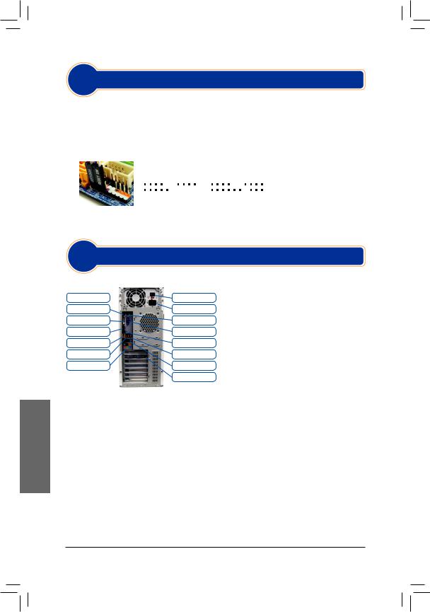
Etape
7 Connexion Des Câbles Aux Connecteurs Internes
7-1 Reliez les câbles aux connecteurs internes et aux en-têtes de la carte mère, y compris les connecteurs IDE/SATA, le connecteur audio du panneau avant, les en-têtes USB, IEEE 1394, etc.
7-2 Attachez le module du panneau avant (différent selon la conception du boîtier, la consistance de l’indicateur de courant, l’indicateur de l’activité du disque dur, les haut-parleurs, la commande de réinitialisation, la commande marche/arrêt, etc.) du boîtier sur l’en-tête du panneau avant (F_PANEL) de la carte mère.
|
Emplacements de broche A : |
Emplacements de broche B : |
MSG : DEL Message/Marche/Veille |
|||||||||||||||||||||||||||
|
+MSG- +PW- |
+SPEAK- |
+MSG- +PW- |
+SPEAK- |
PWR : DEL de marche |
|||||||||||||||||||||||||
|
PW: Commande marche/arrêt |
|||||||||||||||||||||||||||||
|
2 |
20 |
SPEAK: Haut-parleur |
|||||||||||||||||||||||||||
|
1 |
19 HD: DEL d’activité du disque dur |
||||||||||||||||||||||||||||
|
RES: Commande de réinitialisation |
|||||||||||||||||||||||||||||
|
+HD |
— -RES+ |
+HD- |
-RES+ -CI+ |
+PWR- |
|||||||||||||||||||||||||
|
En-tête du panneau avant |
NC |
CI : En-tête d’instructions du châssis |
|||||||||||||||||||||||||||
|
(Remarque) |
Les emplacements de broche du panneau avant peuvent être différentes de ceux |
||||
|
indiqués sur le schéma. Consultez le mode d’emploi de la carte mère pour trouver |
|||||
|
l’emplacement réel des broches. |
|||||
|
Etape |
|||||
|
8 Connexion des périphériques |
|||||
|
Panneau arrière du boîtier |
|||||
|
Alimentation électrique |
Interrupteur |
Une fois que vous avez terminé les étapes |
|||
|
Port pour clavier PS/2 |
Connecteur du cordon |
ci-dessus, reliez les appareils périphériques à |
|||
|
d’alimentation |
l’ordinateur, comme le clavier, la souris, le moniteur, |
||||
|
Port DVI-D |
Port pour souris PS/2 |
||||
|
Port HDMI |
Port D-Sub |
etc. Connectez ensuite à l’alimentation, allumez le |
|||
|
système et installez tous les logiciels requis. |
|||||
|
Ports eSATA |
Connecteur S/PDIF |
||||
|
Port IEEE1394 |
Ports USB |
||||
|
Prises audio |
Port RJ-45 LAN |
||||
|
Carte graphique externe |
Français
— 4 —
![]()
•• La sequenza dell’installazione può differire a seconda del tipo di case e dei dispositivi utilizzati. Le
istruzioni per l’installazione indicate in basso si applicano ai sistemi desktop GIGABYTE e sono solo di riferimento.
•• Per specifiche dettagliate sulla scheda madre, fare riferimento al manuale utente incluso.
•• Accertarsi che i dispositivi siano conformi ai connettori sul computer, prima di installarli.
•• Prima dell’installazione, accertarsi che i dispositivi e il computer siano spenti. Scollegare il cavo
elettrico dalla presa per evitare di danneggiare i dispositivi e i componenti del sistema.
•• Posizionare il computer su una superficie stabile per ovviare ai problemi di un’installazione non corretta dovuta a oscillazioni.
Fase
1 Installazione Della CPU E Della Ventola
A. Installazione di una CPU Intel (saltare questa fase se la scheda madre ha una CPU integrata)
A-1 Fare riferimento alle seguenti istruzioni in base alle specifiche della CPU:
|
•• |
Tipo A: |
||
|
Sollevare la leva del socket della CPU e la piastra metallica si solleva |
|||
|
allo stesso modo. |
|||
|
a. Se il coperchio del socket protettivo è fissato al socket della CPU, è |
|||
|
necessario prima rimuoverlo. |
|||
|
b. Se la copertura della presa dalla piastra protettiva è fissata sulla |
|||
|
piastra di carico in metallo, non rimuoverla in questa fase. La |
|||
|
copertura della presa potrebbe apparire automaticamente fuori dalla |
|||
|
piastra di carico durante il processo di reinnesto della leva dopo aver |
|||
|
•• |
inserito la CPU. |
||
|
Tipo B: |
|||
|
Abbassare la leva A (la più vicina al contrassegno « |
«) allontanandola dal socket per sganciarlo. |
Quindi abbassare la levetta B (la più vicina al contrassegno « «) allontanandola dal socket e alzare. Premere delicatamente sulla leva A per consentire alla placchetta di fermo di alzarsi. Aprire la placchetta.
La levetta A La levetta B
A-2 Afferrare la CPU con il pollice e l’indice. Allineare il segno del pin uno della CPU (triangolo) con l’angolo del pin uno dell’alloggiamento (oppure allineare le tacche della CPU ai segni sull’alloggiamento) e inserire delicatamente la CPU al suo posto.
A-3 Una volta inserita correttamente la CPU, rimettere la piastra e spingere indietro la leva dell’alloggiamento in posizione di blocco.
Una volta correttamente inserita la tipo A, riposizionare con cura la placchetta di fermo. Quindi fissare la levetta B sotto la sua linguetta di arresto. Il coperchio del socket può saltar fuori dalla placchetta di fermo durante l’operazione di aggancio della leva. Infine, per completare l’installazione della CPU, spingere la leva A sotto la sua linguetta di arresto.
 Per istruzioni dettagliate sull’installazione della CPU, fare riferimento al manuale dell’utente.
— 1 —
Italiano
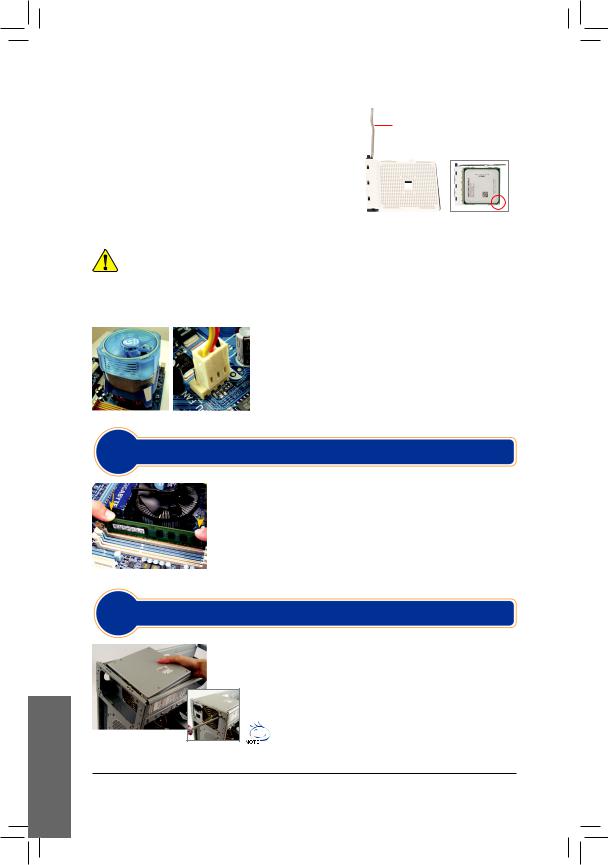
B. Installazione di una CPUAMD (saltare questa fase se la scheda madre ha una CPU integrata)
B-1 Sollevare completamente la leva dell’alloggiamento della CPU.Allineare il pin uno della CPU (simbolo del triangolino) con il segno del triangolo sull’alloggiamento ed inserire delicatamente la CPU. Accertarsi che i pin della CPU si inseriscano perfettamente nei fori.
B-2 Una volta inserita, poggiare un dito al centro della CPU, abbassando la leva dell’alloggiamento e bloccandola in posizione.
Leva dell’alloggiamento della CPU
•• Non forzare la CPU nell’alloggiamento. La CPU non può essere inserita, se orientata in maniera errata. In questo caso, orientare correttamente la CPU.


 •• NON toccare i contatti dell’alloggiamento. Per proteggere l’alloggiamento della CPU, riposizionare sempre le coperture di protezione quando la CPU non è installata.
C. Installazione della ventola della CPU
C-1 Prima di installare la ventola della CPU, aggiungere uno strato sottile di pasta dissipatrice sulla superficie della CPU stessa.
Quindi installare la ventola (fare riferimento al relativo manuale d’installazione)
C-2 Collegare il cavo della ventola al connettore CPU_FAN sulla scheda madre, in modo che possa funzionare correttamente evitando il surriscaldamento della CPU.
2Fase
Installazione Del Modulo Di Memoria
Fare attenzione all’orientamento del modulo di memoria. Distribuire le clip di fissaggio su entrambe le estremità dell ’alloggiamento della memoria. Inserire il  modulo di memoria nell’alloggiamento. Come indicato nell’immagine a sinistra, poggiare le dita sul bordo superiore del modulo di memoria spingendolo verso il basso ed inserendolo in verticale nell’alloggiamento. Le clip sulle estremità
dell’alloggiamento scatteranno, una volta inserito il modulo.
3Fase
Preparazione Del Case E Installazione Dell’alimentazione
UsandoilsistemadesktopGIGABYTEcomeesempio,rimuovereprimaentrambi ilatieilcoperchiodelcaseperinserirel’alimentazione.Posizionarel’alimentatore nel case correttamente e fissarlo con le viti. L’installazione e la posizione dell’alimentazionepossonovariareasecondadeltipodicaseutilizzato.
Pergarantireun’alimentazionesufficientealsistema,siconsigliadi utilizzare un alimentatore di buona qualità.
 Loading…