- Manuals
- Brands
- Gigabyte Manuals
- Motherboard
- GA-Z270P-D3
- User manual
-
Contents
-
Table of Contents
-
Bookmarks
Quick Links
GA-Z270P-D3
User’s Manual
Rev. 1001
12ME-Z270PD3-1001R
For more product details, please visit GIGABYTE’s website.
To reduce the impacts on global warming, the packaging materials of this product
are recyclable and reusable. GIGABYTE works with you to protect the environment.
Related Manuals for Gigabyte GA-Z270P-D3
Summary of Contents for Gigabyte GA-Z270P-D3
-
Page 1
GA-Z270P-D3 User’s Manual Rev. 1001 12ME-Z270PD3-1001R For more product details, please visit GIGABYTE’s website. To reduce the impacts on global warming, the packaging materials of this product are recyclable and reusable. GIGABYTE works with you to protect the environment. -
Page 2
Information in this manual is protected by copyright laws and is the property of GIGABYTE. Changes to the specifications and features in this manual may be made by GIGABYTE without prior notice. No part of this manual may be reproduced, copied, translated, transmitted, or published in any form or by any means without GIGABYTE’s prior written permission. -
Page 3: Table Of Contents
Table of Contents GA-Z270P-D3 Motherboard Layout ……………..4 Chapter 1 Hardware Installation ………………5 Installation Precautions ………………5 1-2 Product Specifications ………………6 Installing the CPU ……………….. 9 Installing the Memory ………………9 Installing an Expansion Card …………….. 10 Back Panel Connectors ……………… 10 Internal Connectors ………………
-
Page 4: Ga-Z270P-D3 Motherboard Layout
GA-Z270P-D3 Motherboard Layout ATX_12V_2X4 KB_MS SYS_FAN1 LGA1151 R_USB30_2 R_USB30_1 USB_LAN AUDIO PCIEX1_1 SATA3 1 0 GA-Z270P-D3 PCIEX16 Realtek ® GbE LAN Intel Z270 ® ® PCIEX1_2 Super I/O PCIEX4_1 CODEC PCIEX1_3 M_BIOS B_BIOS PCIEX4_2 CLR_CMOS SPDIF_O F_AUDIO F_USB2 F_USB1 SYS_FAN3_PUMP…
-
Page 5: Chapter 1 Hardware Installation
Chapter 1 Hardware Installation Installation Precautions The motherboard contains numerous delicate electronic circuits and components which can become damaged as a result of electrostatic discharge (ESD). Prior to installation, carefully read the user’s manual and follow these procedures: • Prior to installation, make sure the chassis is suitable for the motherboard. •…
-
Page 6: 1-2 Product Specifications
Support for ECC Un-buffered DIMM 1Rx8/2Rx8 memory modules (operate in Š non-ECC mode) Support for non-ECC Un-buffered DIMM 1Rx8/2Rx8/1Rx16 memory modules Š Support for Extreme Memory Profile (XMP) memory modules Š (Go to GIGABYTE’s website for the latest supported memory speeds and memory modules.) Onboard Integrated Graphics Processor-Intel HD Graphics support: ® Š Graphics 1 x HDMI port, supporting a maximum resolution of 4096×2160@24 Hz * Support for HDMI 1.4 version.
-
Page 7
Chipset: Š 6 x USB 3.1 Gen 1 ports (4 ports on the back panel, 2 ports available through the internal USB header) 6 x USB 2.0/1.1 ports (2 ports on the back panel, 4 ports available through the internal USB headers) Internal 1 x 24-pin ATX main power connector Š… -
Page 8
* G IGABYTE reserves the right to make any changes to the product specifications and product-related information without prior notice. Please visit the SupportUtility List Please visit GIGABYTE’s website for support lists of CPU, memory page on GIGABYTE’s website to modules, SSDs, and M.2 devices. download the latest version of apps. — 8 -… -
Page 9: Installing The Cpu
• Make sure that the motherboard supports the memory. It is recommended that memory of the same capacity, brand, speed, and chips be used. (Go to GIGABYTE’s website for the latest supported memory speeds and memory modules.) • Always turn off the computer and unplug the power cord from the power outlet before installing the memory to prevent hardware damage.
-
Page 10: Installing An Expansion Card
The four memory sockets are divided into two channels and each channel has two memory sockets as following: Channel A: DDR4_2, DDR4_4 Channel B: DDR4_1, DDR4_3 Dual Channel Memory Configurations Table DDR4_4 DDR4_2 DDR4_3 DDR4_1 2 Modules DS/SS DS/SS DS/SS DS/SS 4 Modules DS/SS DS/SS DS/SS DS/SS (SS=Single-Sided, DS=Double-Sided, «- -«=No Memory) Due to CPU limitations, read the following guidelines before installing the memory in Dual Channel mode. Dual Channel mode cannot be enabled if only one memory module is installed.
-
Page 11
Mic In (Pink) The Mic in jack. To configure 7.1-channel audio, you have to use an HD front panel audio module and enable the multi-channel audio feature through the audio driver. Please visit GIGABYTE’s website for more software information. • When removing the cable connected to a back panel connector, first remove the cable from your device and then remove it from the motherboard. • When removing the cable, pull it straight out from the connector. Do not rock it side to side to prevent an electrical short inside the cable connector. -
Page 12: Internal Connectors
Internal Connectors ATX_12V_2X4 F_AUDIO SPDIF_O CPU_FAN F_USB30 SYS_FAN1/2 F_USB1/F_USB2 SYS_FAN3_PUMP SATA3 0/1/2/3/4/5 M2P_32G F_PANEL CLR_CMOS Read the following guidelines before connecting external devices: • First make sure your devices are compliant with the connectors you wish to connect. • Before installing the devices, be sure to turn off the devices and your computer. Unplug the power cord from the power outlet to prevent damage to the devices.
-
Page 13
1/2) ATX_12V_2X4/ATX (2×4 12V Power Connector and 2×12 Main Power Connector) With the use of the power connector, the power supply can supply enough stable power to all the components on the motherboard. Before connecting the power connector, first make sure the power supply is turned off and all devices are properly installed. The power connector possesses a foolproof design. Connect the power supply cable to the power connector in the correct orientation. -
Page 14
5) SYS_FAN3_PUMP (System Fan/Water Cooling Pump Header) The pump header is 4-pin and possesses a foolproof insertion design. Most fan headers possess a foolproof insertion design. When connecting a fan cable, be sure to connect it in the correct orientation (the black connector wire is the ground wire). -
Page 15
Installation Notices for the M.2, and SATA Connectors: Due to the limited number of lanes provided by the Chipset, the availability of the SATA connectors may be affected by the type of device installed in the M2P_32G connector. The M2P_32G connector shares bandwidth with the SATA3 0 connector. Refer to the following table for details. -
Page 16
9) F_AUDIO (Front Panel Audio Header) The front panel audio header supports Intel High Definition audio (HD) and AC’97 audio. You may connect your chassis front panel audio module to this header. Make sure the wire assignments of the module connector match the pin assignments of the motherboard header. Incorrect connection between the module connector and the motherboard header will make the device unable to work or even damage it. For HD Front Panel Audio: For AC’97 Front Panel Audio: Pin No. -
Page 17
12) F_USB1/F_USB2 (USB 2.0/1.1 Headers) The headers conform to USB 2.0/1.1 specification. Each USB header can provide two USB ports via an optional USB bracket. For purchasing the optional USB bracket, please contact the local dealer. Pin No. Definition Pin No. Definition F_USB30 Power (5V) USB DY+ F_ U Power (5V) USB DX- USB DY- No Pin USB DX+ •… -
Page 18
15) BAT (Battery) The battery provides power to keep the values (such as BIOS configurations, date, and time information) in the CMOS when the computer is turned off. Replace the battery when the battery voltage drops to a low level, or the CMOS values may not be accurate or may be lost. You may clear the CMOS values by removing the battery: 1. Turn off your computer and unplug the power cord. 2. Gently remove the battery from the battery holder and wait for one minute. (Or use a metal object like a screwdriver to touch the positive and negative terminals of the battery holder, making them short for 5 seconds.) 3. -
Page 19: Chapter 2 Bios Setup
To access the BIOS Setup program, press the <Delete> key during the POST when the power is turned on. To upgrade the BIOS, use either the GIGABYTE Q-Flash or @BIOS utility. Q-Flash allows the user to quickly and easily upgrade or back up BIOS without entering the operating system.
-
Page 20
M.I.T. Whether the system will work stably with the overclock/overvoltage settings you made is dependent on your overall system configurations. Incorrectly doing overclock/overvoltage may result in damage to CPU, chipset, or memory and reduce the useful life of these components. This page is for advanced users only and we recommend you not to alter the default settings to prevent system instability or other unexpected results. -
Page 21
` Advanced CPU Core Settings & CPU Clock Ratio, CPU Frequency, FCLK Frequency for Early Power On The settings above are synchronous to those under the same items on the Advanced Frequency Settings menu. & AVX Offset (Note) AVX offset is the negative offset of AVX ratio. &… -
Page 22
& C3 State Support (Note 1) Allows you to determine whether to let the CPU enter C3 mode in system halt state. When enabled, the CPU core frequency and voltage will be reduced during system halt state to decrease power consumption. The C3 state is a more enhanced power-saving state than C1. -
Page 23
& System Memory Multiplier Allows you to set the system memory multiplier. Auto sets memory multiplier according to memory SPD data. (Default: Auto) & Memory Ref Clock Allows you to manually adjust the memory reference clock. (Default: Auto) & Memory Odd Ratio(100/133 or 200/266) Enabled allows Qclk to run in odd frequency. -
Page 24
` Channel A/B Memory Sub Timings This sub-menu provides memory timing settings for each channel of memory. The respective timing setting screens are configurable only when Memory Timing Mode is set to Manual or Advanced Manual. Note: Your system may become unstable or fail to boot after you make changes on the memory timings. If this occurs, please reset the board to default values by loading optimized defaults or clearing the CMOS values. -
Page 25
` Smart Fan 5 Settings & Monitor Allows you to select a target to monitor and to make further adjustment. (Default: CPU FAN) & Fan Speed Control Allows you to determine whether to enable the fan speed control function and adjust the fan speed. Allows the fan to run at different speeds according to the temperature. -
Page 26: System
System This section provides information on your motherboard model and BIOS version. You can also select the default language used by the BIOS and manually set the system time. & Access Level Displays the current access level depending on the type of password protection used. (If no password is set, the default will display as Administrator.) The Administrator level allows you to make changes to all BIOS settings;…
-
Page 27: Bios
A password is required for booting the system and for entering the BIOS Setup program. System (Default) & Full Screen LOGO Show Allows you to determine whether to display the GIGABYTE Logo at system startup. Disabled skips the GIGABYTE Logo when the system starts up. (Default: Enabled) & Boot Option Priorities Specifies the overall boot order from the available devices. Removable storage devices that support GPT format will be prefixed with «UEFI:» string on the boot device list. To boot from an operating system that…
-
Page 28
& SATA Support All Sata Devices All SATA devices are functional in the operating system and during the POST. (Default) Last Boot HDD Only Except for the previous boot drive, all SATA devices are disabled before the OS boot process completes. This item is configurable only when Fast Boot is set to Enabled or Ultra Fast. -
Page 29
& Storage Boot Option Control Allows you to select whether to enable the UEFI or legacy option ROM for the storage device controller. Do not launch Disables option ROM. Enables legacy option ROM only. (Default) Legacy UEFI Enables UEFI option ROM only. This item is configurable only when CSM Support is set to Enabled. & Other PCI devices Allows you to select whether to enable the UEFI or Legacy option ROM for the PCI device controller other than the LAN, storage device, and graphics controllers. Do not launch Disables option ROM. Enables legacy option ROM only. Legacy UEFI Enables UEFI option ROM only. (Default) This item is configurable only when CSM Support is set to Enabled. &… -
Page 30: Peripherals
Peripherals & Initial Display Output Specifies the first initiation of the monitor display from the installed PCI Express graphics card or the onboard graphics. IGFX Sets the onboard graphics as the first display. Sets the graphics card on the PCIEX16 slot as the first display. (Default) PCIe 1 Slot Sets the graphics card on the PCIEX4_1 slot as the first display. PCIe 2 Slot Sets the graphics card on the PCIEX4_2 slot as the first display. PCIe 3 Slot & OnBoard LAN Controller Enables or disables the onboard LAN function. (Default: Enabled) If you wish to install a 3rd party add-in network card instead of using the onboard LAN, set this item to Disabled.
-
Page 31
` Super IO Configuration & Serial Port Enables or disables the onboard serial port. (Default: Enabled) ` Intel(R) Bios Guard Technology Enables or disables the Intel BIOS Guard feature, which protects the BIOS from malicious attacks. ® ` Network Stack Configuration & Network Stack Disables or enables booting from the network to install a GPT format OS, such as installing the OS from the Windows Deployment Services server. -
Page 32
` SATA And RST Configuration & SATA Controller(s) Enables or disables the integrated SATA controllers. (Default: Enabled) & SATA Mode Selection Enables or disables RAID for the SATA controllers integrated in the Chipset or configures the SATA controllers to AHCI mode. Enables RAID for the SATA controller. Intel RST Premium With Intel Optane System Acceleration AHCI C onfigures the SATA controllers to AHCI mode. Advanced Host Controller Interface (AHCI) is an interface specification that allows the storage driver to enable advanced Serial ATA features such as Native Command Queuing and hot plug. (Default) &… -
Page 33: Chipset
Chipset & VT-d (Note) Enables or disables Intel Virtualization Technology for Directed I/O. (Default: Enabled) ® & Internal Graphics Enables or disables the onboard graphics function. (Default: Auto) & DVMT Pre-Allocated Allows you to set the onboard graphics memory size. Options are: 32M~1024M. (Default: 32M) &…
-
Page 34: Power
Power & Platform Power Management Enables or disables the Active State Power Management function (ASPM). (Default: Disabled) & PEG ASPM Allows you to configure the ASPM mode for the device connected to the CPU PEG bus. This item is configurable only when Platform Power Management is set to Enabled. (Default: Enabled) &…
-
Page 35
& Power On Password Set the password when Power On By Keyboard is set to Password. Press <Enter> on this item and set a password with up to 5 characters and then press <Enter> to accept. To turn on the system, enter the password and press <Enter>. Note: To cancel the password, press <Enter>… -
Page 36: Save & Exit
Save & Exit & Save & Exit Setup Press <Enter> on this item and select Yes. This saves the changes to the CMOS and exits the BIOS Setup program. Select No or press <Esc> to return to the BIOS Setup Main Menu. &…
-
Page 37: Chapter 3 Appendix
The actual BIOS Setup menu options you will see shall depend on the motherboard you have and the BIOS version. C-1. Using EZ RAID GIGABYTE motherboards provide you with the EZ RAID feature, allowing you to quickly configure a RAID array with simplified steps. Steps: 1. After restarting the computer, enter the BIOS Setup and go to Peripherals. Press <Enter> on the EZ RAID item. Select the type of hard drives you use for RAID in the Type tab and then press <Enter>.
-
Page 38
5. Enter the array capacity and press <Enter>. Finally press <Enter> on the Create Volume item to begin creating the RAID array. When prompted to confirm whether to create this volume, press <Y> to confirm or <N> to cancel. 6. When completed, you can see detailed information about the RAID array in the DISK/VOLUME INFORMATION section, including the RAID level, stripe block size, array name, and array capacity, etc. To exit the RAID BIOS utility, press <Esc> or select 6. Exit in MAIN MENU. Please visit GIGABYTE’s website for details on configuring a RAID array. — 38 -… -
Page 39
Installing the SATA RAID/AHCI Driver and Operating System With the correct BIOS settings, you are ready to install the operating system. Installing the Operating System As some operating systems already include Intel SATA RAID/AHCI driver, you do not need to install separate ® RAID/AHCI driver during the Windows installation process. After the operating system is installed, we recommend that you install all required drivers from the motherboard driver disk using «Xpress Install» to ensure system performance and compatibility. If the operating system to be installed requires that you provide additional SATA RAID/AHCI driver during the OS installation process, please refer to the steps below: 1. -
Page 40: Drivers Installation
Run.exe program.) «Xpress Install» will automatically scan your system and then list all of the drivers that are recommended to install. You can click the Xpress Install button and «Xpress Install» will install all of the selected drivers. Or click the arrow icon to individually install the drivers you need. Please visit GIGABYTE’s website Please visit GIGABYTE’s website for more software information. for details on configuring the audio software. — 40 -…
-
Page 41: Regulatory Statements
Contravention will be prosecuted. We believe that the information contained herein was accurate in all respects at the time of printing. GIGABYTE cannot, however, assume any responsibility for errors or omissions in this text. Also note that the information in this document is subject to change without notice and should not be construed as a commitment by GIGABYTE.
-
Page 42
FCC Notice (U.S.A. Only) This equipment has been tested and found to comply with the limits for a Class B digital device, pursuant to Part 15 of the FCC Rules. These limits are designed to provide reasonable protection against harmful interference in a residential installation. This equipment generates, uses, and can radiate radio frequency energy and, if not installed and used in accordance with the instructions, may cause harmful interference to radio communications. -
Page 43
— 43 -… -
Page 44: Contact Us
Contact Us GIGA-BYTE TECHNOLOGY CO., LTD. Address: No.6, Baoqiang Rd., Xindian Dist., New Taipei City 231, Taiwan TEL: +886-2-8912-4000, FAX: +886-2-8912-4005 Tech. and Non-Tech. Support (Sales/Marketing) : http://esupport.gigabyte.com WEB address (English): http://www.gigabyte.com WEB address (Chinese): http://www.gigabyte.tw GIGABYTE eSupport • To submit a technical or non-technical (Sales/Marketing) question, please link to: http://esupport.gigabyte.com…
![]()
GA-Z270P-D3
User’s Manual
Rev. 1001
12ME-Z270PD3-1001R
For more product details, please visit GIGABYTE’s website.
To reduce the impacts on global warming, the packaging materials of this product are recyclable and reusable. GIGABYTE works with you to protect the environment.

Motherboard
GA-Z270P-D3
Motherboard
GA-Z270P-D3
Dec. 7, 2016
Dec. 7, 2016
Copyright
© 2016 GIGA-BYTE TECHNOLOGY CO., LTD. All rights reserved.
The trademarks mentioned in this manual are legally registered to their respective owners.
Disclaimer
Information in this manual is protected by copyright laws and is the property of GIGABYTE.
ChangestothespecificationsandfeaturesinthismanualmaybemadebyGIGABYTEwithoutpriornotice.
No part of this manual may be reproduced, copied, translated, transmitted, or published in any form or by any means without GIGABYTE’s prior written permission.
In order to assist in the use of this product, carefully read the User’s Manual.
For product-related information, check on our website at: http://www.gigabyte.com
Identifying Your Motherboard Revision
The revision number on your motherboard looks like this: «REV: X.X.» For example, «REV: 1.0» means the revision of the motherboard is 1.0. Check your motherboard revision before updating motherboard BIOS, drivers, or when looking for technical information.
Example:

Table of Contents
|
GA-Z270P-D3 Motherboard Layout……………………………………………………………………… |
4 |
|
|
Chapter 1 Hardware Installation………………………………………………………………………….. |
5 |
|
|
1-1 |
Installation Precautions…………………………………………………………………………. |
5 |
|
1-2 |
Product Specifications………………………………………………………………………….. |
6 |
|
1-3 |
Installing the CPU………………………………………………………………………………… |
9 |
|
1-4 |
Installing the Memory……………………………………………………………………………. |
9 |
|
1-5 Installing an Expansion Card……………………………………………………………….. |
10 |
|
|
1-6 |
Back Panel Connectors………………………………………………………………………. |
10 |
|
1-7 |
Internal Connectors……………………………………………………………………………. |
12 |
|
Chapter 2 BIOS Setup……………………………………………………………………………………… |
19 |
|
|
2-1 |
Startup Screen…………………………………………………………………………………… |
19 |
|
2-2 |
M.I.T…………………………………………………………………………………………………. |
20 |
|
2-3 |
System……………………………………………………………………………………………… |
26 |
|
2-4 |
BIOS………………………………………………………………………………………………… |
27 |
|
2-5 |
Peripherals………………………………………………………………………………………… |
30 |
|
2-6 |
Chipset……………………………………………………………………………………………… |
33 |
|
2-7 |
Power……………………………………………………………………………………………….. |
34 |
|
2-8 |
Save & Exit……………………………………………………………………………………….. |
36 |
|
Chapter 3 Appendix…………………………………………………………………………………………. |
37 |
|
|
3-1 Configuring a RAID Set………………………………………………………………………. |
37 |
|
|
3-2 |
Drivers Installation……………………………………………………………………………… |
40 |
|
Regulatory Statements…………………………………………………………………………………. |
41 |
|
|
Contact Us………………………………………………………………………………………………….. |
44 |
— 3 —
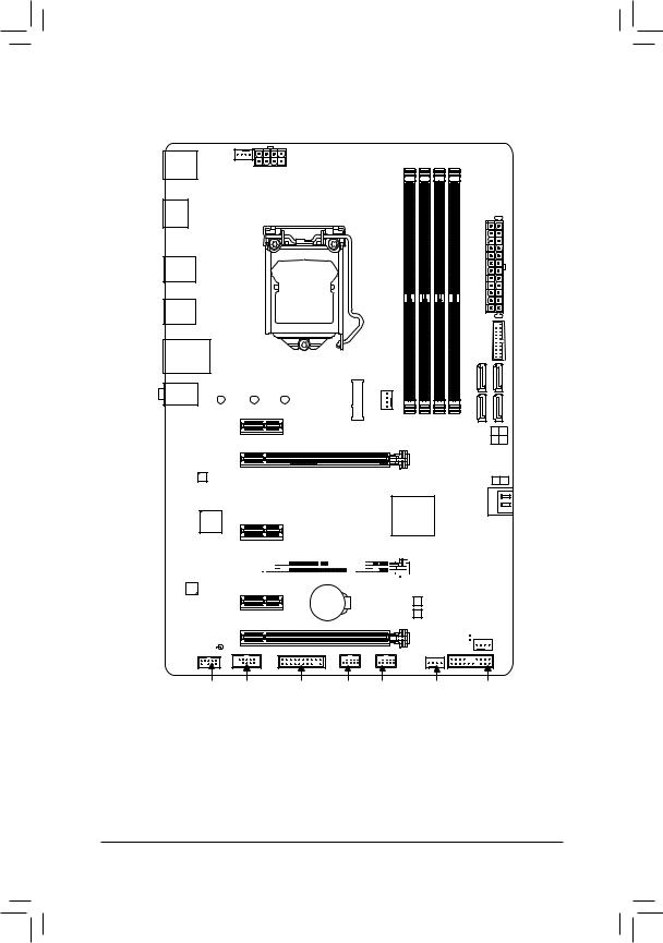
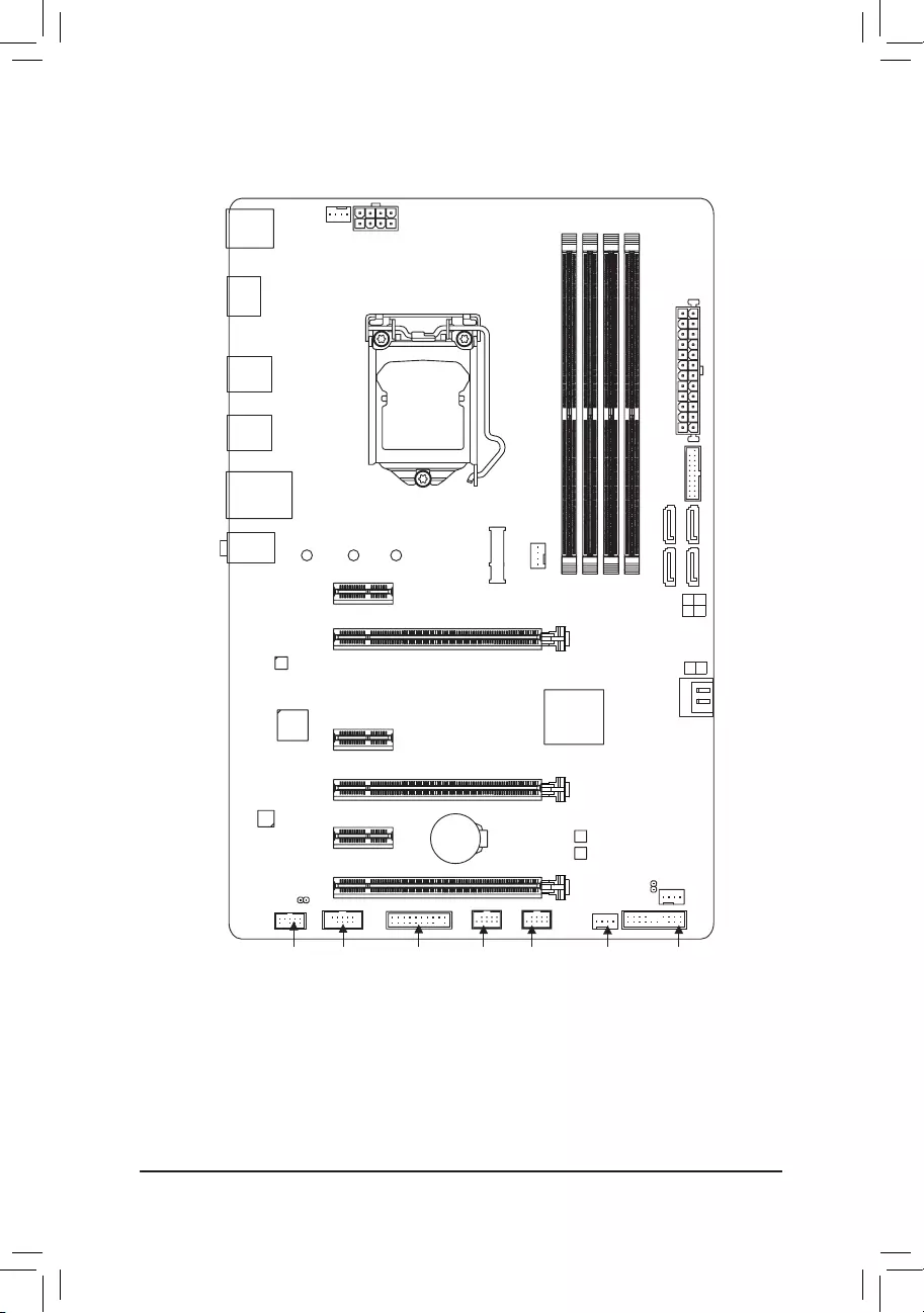
GA-Z270P-D3 Motherboard Layout
|
KB_MS |
SYS_FAN1 |
|
|
HDMI |
||
|
R_USB30_2 |
||
|
R_USB30_1 |
||
|
USB_LAN |
||
|
AUDIO |
80 |
60 |
|
PCIEX1_1 |
||
|
Realtek® |
PCIEX16 |
|
|
GbE LAN |
||
|
iTE® |
PCIEX1_2 |
|
|
Super I/O |
||
ATX_12V_2X4
LGA1151
GA-Z270P-D3
ATX
|
FAN |
F USB30 |
||
|
CPU_ |
|||
|
DDR44 DDR42 DDR43 DDR41 |
SATA3 |
1 |
0 |
|
3 |
2 |
||
|
SATA3 |
5 4 |
||
|
Intel® Z270 |
PCIEX4_1
CODEC 


 PCIEX1_3
BAT
PCIEX4_2
SPDIF_O
M_BIOS
B_BIOS
CLR_CMOS
SYS_FAN2
F_AUDIO COM TPM F_USB2 F_USB1 SYS_FAN3_PUMP F_PANEL
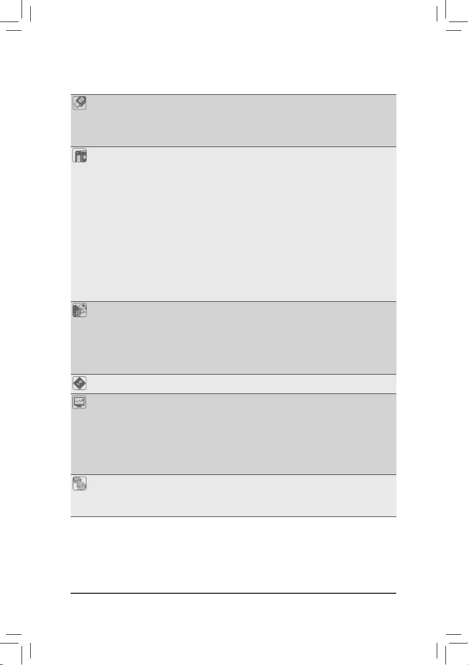
Box Contents
|
55 |
GA-Z270P-D3 motherboard |
55 |
Two SATA cables |
|
55 |
Motherboard driver disk |
55 |
I/O Shield |
|
55 |
User’s Manual |
55 |
One G Connector |
*The box contents above are for reference only and the actual items shall depend on the product package you obtain. The box contents are subject to change without notice.
—4 —

Chapter 1 Hardware Installation
1-1 Installation Precautions
The motherboard contains numerous delicate electronic circuits and components which can become damaged as a result of electrostatic discharge (ESD). Prior to installation, carefully read the user’s manual and follow these procedures:
•• Prior to installation, make sure the chassis is suitable for the motherboard.
•• Prior to installation, do not remove or break motherboard S/N (Serial Number) sticker or warranty sticker provided by your dealer. These stickers are required for warranty validation.
•• Always remove the AC power by unplugging the power cord from the power outlet before installing or removing the motherboard or other hardware components.
•• When connecting hardware components to the internal connectors on the motherboard, make sure they are connected tightly and securely.
•• When handling the motherboard, avoid touching any metal leads or connectors.
•• It is best to wear an electrostatic discharge (ESD) wrist strap when handling electronic components such as a motherboard, CPU or memory. If you do not have an ESD wrist strap, keep your hands dry and first touch a metal object to eliminate static electricity.
•• Prior to installing the motherboard, please have it on top of an antistatic pad or within an electrostatic shielding container.
•• Before connecting or unplugging the power supply cable from the motherboard, make sure the power supply has been turned off.
•• Before turning on the power, make sure the power supply voltage has been set according to the local voltage standard.
•• Before using the product, please verify that all cables and power connectors of your hardware components are connected.
•• To prevent damage to the motherboard, do not allow screws to come in contact with the motherboard circuit or its components.
•• Make sure there are no leftover screws or metal components placed on the motherboard or within the computer casing.
•• Do not place the computer system on an uneven surface.
•• Do not place the computer system in a high-temperature or wet environment.
•• Turning on the computer power during the installation process can lead to damage to system components as well as physical harm to the user.
•• If you are uncertain about any installation steps or have a problem related to the use of the product, please consult a certified computer technician.
•• If you use an adapter, extension power cable, or power strip, ensure to consult with its installation and/or grounding instructions.
— 5 —
|
1-2 |
Product Specifications |
|
|
CPU |
Support for 7th and 6th generation Intel® Core™ i7 processors/ |
|
|
Intel® Core™ i5 processors/Intel® Core™ i3 processors/ |
||
|
Intel® Pentium® processors/Intel® Celeron® processors in the LGA1151 package |
||
|
(Go to GIGABYTE’s website for the latest CPU support list.) |
||
|
L3 cache varies with CPU |
||
|
Chipset |
Intel® Z270 Express Chipset |
|
|
Memory |
4 x DDR4 DIMM sockets supporting up to 64 GB of system memory |
|
|
* Due to a Windows 32-bit operating system limitation, when more than 4 GB of physical |
||
|
memory is installed, the actual memory size displayed will be less than the size of |
||
|
the physical memory installed. |
Dual channel memory architecture
Support for DDR4 2400/2133 MHz memory modules
Support for ECC Un-buffered DIMM 1Rx8/2Rx8 memory modules (operate in non-ECC mode)
Support for non-ECC Un-buffered DIMM 1Rx8/2Rx8/1Rx16 memory modulesSupport for Extreme Memory Profile (XMP) memory modules
(Go to GIGABYTE’s website for the latest supported memory speeds and memory modules.)
|
Onboard |
Integrated Graphics Processor-Intel® HD Graphics support: |
||
|
Graphics |
— |
1 x HDMI port, supporting a maximum resolution of 4096×2160@24 Hz |
|
|
* Support for HDMI 1.4 version. |
|||
|
Maximum shared memory of 1 GB |
|||
|
Audio |
Realtek® ALC887 codec |
||
|
High Definition Audio |
|||
|
2/4/5.1/7.1-channel |
|||
|
Support for S/PDIF Out |
|||
|
LAN |
Realtek® GbE LAN chip (10/100/1000 Mbit) |
||
|
Expansion Slots |
1 x PCI Express x16 slot, running at x16 (PCIEX16) |
||
|
* For optimum performance, if only one PCI Express graphics card is to be installed, |
|||
|
be sure to install it in the PCIEX16 slot. |
|||
|
2 x PCI Express x16 slots, running at x4 (PCIEX4_1/PCIEX4_2) |
|||
|
3 x PCI Express x1 slots |
|||
|
(All of the PCI Express slots conform to PCI Express 3.0 standard.) |
|||
|
Multi-Graphics |
Support for AMD Quad-GPU CrossFireX™ and 2-Way AMD CrossFire™ |
||
|
Technology |
technologies (PCIEX16 and PCIEX4) |
||
|
Storage Interface |
Chipset: |
||
|
— |
1 x M.2 connector (Socket 3, M key, type 2242/2260/2280 SATA and PCIe |
||
|
x4/x2 SSD support) |
|||
|
— |
6 x SATA 6Gb/s connectors |
||
|
— |
Support for RAID 0, RAID 1, RAID 5, and RAID 10 |
||
|
* Refer to «1-7 Internal Connectors,» for the installation notices for the M.2 and SATA |
|||
|
connectors. |
— 6 —
|
USB |
Chipset: |
|
|
— 6 x USB 3.1 Gen 1 ports (4 ports on the back panel, 2 ports available through |
||
|
the internal USB header) |
||
|
— 6 x USB 2.0/1.1 ports (2 ports on the back panel, 4 ports available through |
||
|
the internal USB headers) |
||
|
Internal |
1 x 24-pin ATX main power connector |
|
|
Connectors |
1 x 8-pin ATX 12V power connector |
|
|
1 x CPU fan header |
||
|
2 x system fan headers |
||
|
1 x system fan/water cooling pump header |
||
|
6 x SATA 6Gb/s connectors |
||
|
1 x M.2 Socket 3 connector |
||
|
1 x front panel header |
||
|
1 x front panel audio header |
||
|
1 x S/PDIF Out header |
||
|
1 x USB 3.1 Gen 1 header |
||
|
2 x USB 2.0/1.1 headers |
||
|
1 x Trusted Platform Module (TPM) header |
||
|
1 x serial port header |
||
|
1 x Clear CMOS jumper |
||
|
Back Panel |
1 x PS/2 mouse port |
|
|
Connectors |
1 x PS/2 Keyboard port |
|
|
1 x HDMI port |
||
|
4 x USB 3.1 Gen 1 ports |
||
|
2 x USB 2.0/1.1 ports |
||
|
1 x RJ-45 port |
||
|
3 x audio jacks (Line In, Line Out, Mic In) |
||
|
I/O Controller |
iTE® I/O Controller Chip |
|
|
Hardware |
Voltage detection |
|
|
Monitor |
Temperature detection |
|
|
Fan speed detection |
||
|
Overheating warning |
||
|
Fan fail warning |
||
|
Fan speed control |
*Whether the fan (pump) speed control function is supported will depend on the fan (pump) you install.
|
BIOS |
2 x 64 Mbit flash |
|
|
Use of licensed AMI UEFI BIOS |
||
|
Support for DualBIOS™ |
||
|
PnP 1.0a, DMI 2.7, WfM 2.0, SM BIOS 2.7, ACPI 5.0 |
— 7 —
|
Unique Features |
Support for APP Center |
||
|
* Available applications in APP Center may vary by motherboard model. Supported |
|||
|
functionsofeachapplicationmayalsovarydependingonmotherboardspecifications. |
|||
|
— |
3D OSD |
||
|
— |
@BIOS |
||
|
— |
Ambient LED |
||
|
— |
AutoGreen |
||
|
— |
BIOS Setup |
||
|
— |
Color Temperature |
||
|
— |
Cloud Station |
||
|
— |
EasyTune |
||
|
— |
Easy RAID |
||
|
— |
Fast Boot |
||
|
— |
Game Boost |
||
|
— |
ON/OFF Charge |
||
|
— |
Platform Power Management |
||
|
— |
Smart Backup |
||
|
— |
Smart Keyboard |
||
|
— |
Smart TimeLock |
||
|
— |
System Information Viewer |
||
|
— |
USB Blocker |
||
|
— |
V-Tuner |
||
|
Support for 3TB+ Unlock |
|||
|
Support for Q-Flash |
|||
|
Support for Xpress Install |
|||
|
Bundled |
Norton® Internet Security (OEM version) |
||
|
Software |
Intel® Optane™ Memory Ready |
||
|
cFosSpeed |
|||
|
Operating |
Support for Windows 10/8.1 64-bit |
||
|
System |
Support for Windows 7 32-bit/64-bit |
||
|
* Operating systems supported may vary depending on your processor |
|||
|
model. |
|||
|
* Please download the «Windows USB Installation Tool» from GIGABYTE’s |
|||
|
website and install it before installing Windows 7. |
|||
|
Form Factor |
ATX Form Factor; 30.5cm x 19.9cm |
*GIGABYTE reserves the right to make any changes to the product specifications and product-related information without prior notice.
Please visit GIGABYTE’s website for support lists of CPU, memory modules, SSDs, and M.2 devices.
— 8 —
Please visit the SupportUtility List page on GIGABYTE’s website to download the latest version of apps.
|
1-3 |
Installing the CPU |
|
|
Read the following guidelines before you begin to install the CPU: |
||
|
•• |
Make sure that the motherboard supports the CPU. |
|
|
(Go to GIGABYTE’s website for the latest CPU support list.) |
||
|
•• |
Always turn off the computer and unplug the power cord from the power outlet before installing the |
|
|
CPU to prevent hardware damage. |
||
|
•• |
Locate the pin one of the CPU. The CPU cannot be inserted if oriented incorrectly. (Or you may |
|
|
locate the notches on both sides of the CPU and alignment keys on the CPU socket.) |
||
|
•• |
Apply an even and thin layer of thermal grease on the surface of the CPU. |
|
|
•• |
Do not turn on the computer if the CPU cooler is not installed, otherwise overheating and damage |
|
|
of the CPU may occur. |
||
|
•• |
Set the CPU host frequency in accordance with the CPU specifications. It is not recommended |
|
|
that the system bus frequency be set beyond hardware specifications since it does not meet the |
||
|
standard requirements for the peripherals. If you wish to set the frequency beyond the standard |
||
|
specifications, please do so according to your hardware specifications including the CPU, graphics |
||
|
card, memory, hard drive, etc. |
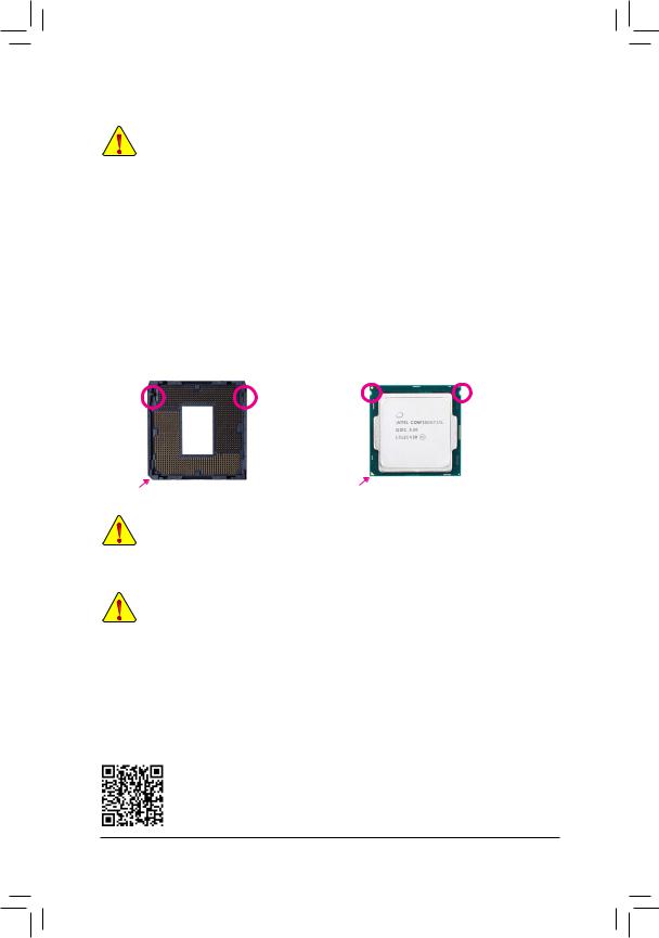
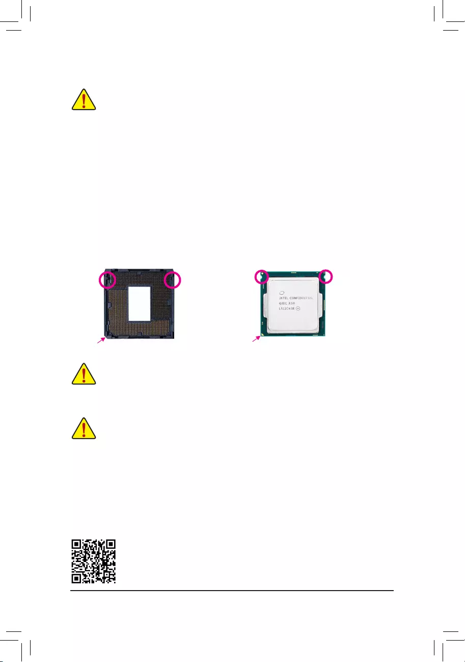
Installing the CPU
Locate the alignment keys on the motherboard CPU socket and the notches on the CPU.
|
LGA1151 CPU Socket |
LGA1151 CPU |
||
|
Alignment |
Alignment |
Notch |
Notch |
|
Key |
Key |
|
Pin One Corner of the CPU Socket |
Triangle Pin One Marking on the CPU |
Do not remove the CPU socket cover before inserting the CPU. It may pop off from the load plate automatically during the process of re-engaging the lever after you insert the CPU.
1-4 Installing the Memory
Read the following guidelines before you begin to install the memory:
•• Make sure that the motherboard supports the memory. It is recommended that memory of the same capacity, brand, speed, and chips be used.
(Go to GIGABYTE’s website for the latest supported memory speeds and memory modules.)
•• Always turn off the computer and unplug the power cord from the power outlet before installing the memory to prevent hardware damage.
•• Memory modules have a foolproof design. A memory module can be installed in only one direction. If you are unable to insert the memory, switch the direction.
Dual Channel Memory Configuration
This motherboard provides four memory sockets and supports Dual Channel Technology. After the memory is installed, the BIOS will automatically detect the specifications and capacity of the memory. Enabling Dual
Channel memory mode will double the original memory bandwidth.
Please visit GIGABYTE’s website for details on hardware installation.
— 9 —

The four memory sockets are divided into two channels and each channel has two memory sockets as following:
Channel A: DDR4_2, DDR4_4Channel B: DDR4_1, DDR4_3
Dual Channel Memory Configurations Table
|
DDR4_4 |
DDR4_2 |
DDR4_3 |
DDR4_1 |
|
|
2 Modules |
— — |
DS/SS |
— — |
DS/SS |
|
DS/SS |
— — |
DS/SS |
— — |
|
|
4 Modules |
DS/SS |
DS/SS |
DS/SS |
DS/SS |
(SS=Single-Sided, DS=Double-Sided, «- -«=No Memory)
Due to CPU limitations, read the following guidelines before installing the memory in Dual Channel mode.
1.Dual Channel mode cannot be enabled if only one memory module is installed.
2.When enabling Dual Channel mode with two or four memory modules, it is recommended that memory of the same capacity, brand, speed, and chips be used and installed in the same colored sockets.
1-5 Installing an Expansion Card
Read the following guidelines before you begin to install an expansion card:
•• Make sure the motherboard supports the expansion card. Carefully read the manual that came with your expansion card.
•• Always turn off the computer and unplug the power cord from the power outlet before installing an expansion card to prevent hardware damage.
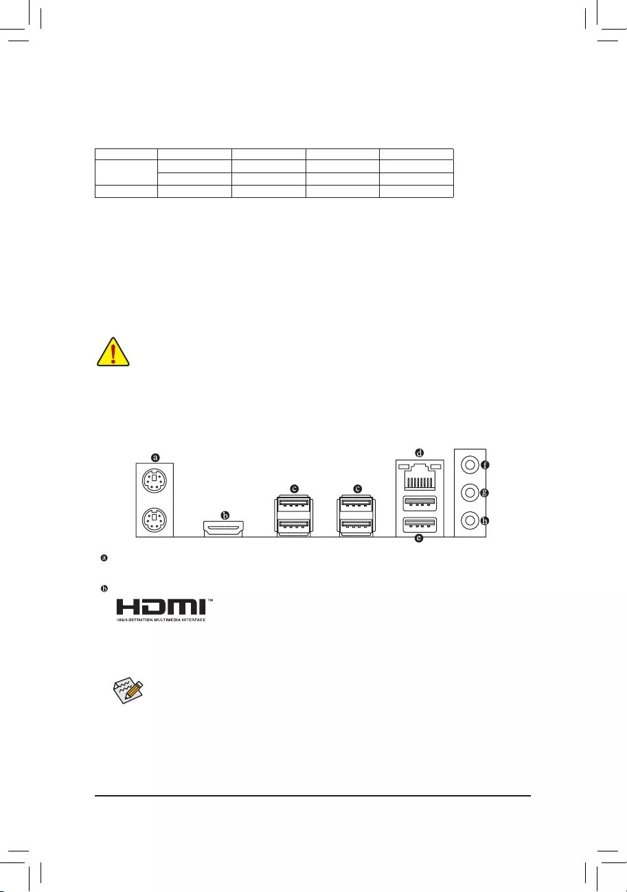
1-6 Back Panel Connectors
PS/2 Keyboard and PS/2 Mouse Port
Use the upper port (green) to connect a PS/2 mouse and the lower port (purple) to connect a PS/2 keyboard.
HDMI Port
 The HDMI port is HDCP compliant and supports Dolby TrueHD and DTS HD Master Audio formats. It also supports up to 192 KHz/16bit 8-channel LPCM audio output. You can use this port to connect your HDMI-supported monitor. The maximum supported
resolution is 4096×2160@24 Hz, but the actual resolutions supported are dependent on the monitor being used.
After installing the HDMI device, make sure to set the default sound playback device to HDMI. (The item name may differ depending on your operating system.)
— 10 —
![]()
USB 3.1 Gen 1 Port
The USB 3.1 Gen 1 port supports the USB 3.1 Gen 1 specification and is compatible to the USB 2.0 specification. Use this port for USB devices.
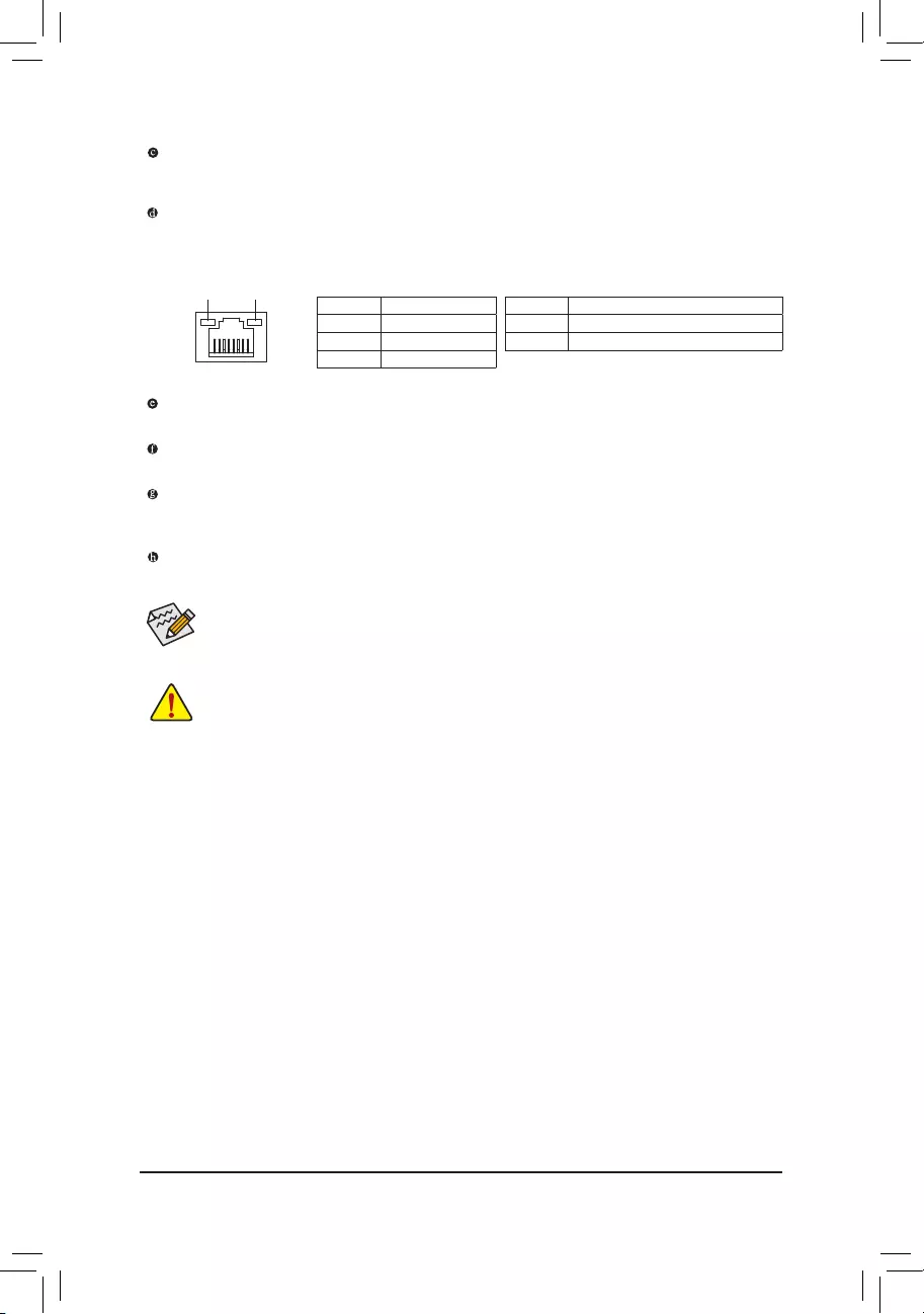
RJ-45 LAN Port
The Gigabit Ethernet LAN port provides Internet connection at up to 1 Gbps data rate. The following describes the states of the LAN port LEDs.
|
Connection/ |
Connection/Speed LED: |
Activity LED: |
|||||||||||||||||
|
Speed LED |
Activity LED |
||||||||||||||||||
|
State |
Description |
State |
Description |
||||||||||||||||
|
Orange |
1 Gbps data rate |
Blinking |
Data transmission or receiving is occurring |
||||||||||||||||
|
Green |
100 Mbps data rate |
Off |
No data transmission or receiving is occurring |
||||||||||||||||
|
Off |
10 Mbps data rate |
||||||||||||||||||
|
LAN Port |
|||||||||||||||||||
USB 2.0/1.1 Port
The USB port supports the USB 2.0/1.1 specification. Use this port for USB devices.
Line In (Blue)
The line in jack. Use this audio jack for line in devices such as an optical drive, walkman, etc.
Line Out (Green)
The line out jack. Use this audio jack for a headphone or 2-channel speaker. This jack can be used to connect front speakers in a 4/5.1/7.1-channel audio configuration.
Mic In (Pink)
The Mic in jack.
 To configure 7.1-channel audio, you have to use an HD front panel audio module and enable the
multi-channel audio feature through the audio driver. Please visit GIGABYTE’s website for more software information.
•• When removing the cable connected to a back panel connector, first remove the cable from your device and then remove it from the motherboard.
•• When removing the cable, pull it straight out from the connector. Do not rock it side to side to prevent an electrical short inside the cable connector.
— 11 —
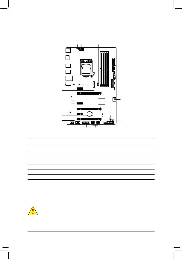
|
1-7 |
Internal Connectors |
|||||
|
4 |
1 |
3 |
||||
|
2 |
||||||
|
11 |
||||||
|
7 |
6 |
|||||
|
6 |
||||||
|
15 |
16 |
|||||
|
10 |
4 |
|||||
|
9 |
14 |
13 |
12 |
5 |
8 |
|
|
1) |
ATX_12V_2X4 |
9) |
F_AUDIO |
|||
|
2) |
ATX |
10) |
SPDIF_O |
|||
|
3) |
CPU_FAN |
11) |
F_USB30 |
|||
|
4) |
SYS_FAN1/2 |
12) |
F_USB1/F_USB2 |
|||
|
5) |
SYS_FAN3_PUMP |
13) |
TPM |
|||
|
6) |
SATA3 0/1/2/3/4/5 |
14) |
COM |
|||
|
7) |
M2P_32G |
15) |
BAT |
|||
|
|
F_PANEL |
16) |
CLR_CMOS |
Read the following guidelines before connecting external devices:
•• First make sure your devices are compliant with the connectors you wish to connect.
•• Before installing the devices, be sure to turn off the devices and your computer. Unplug the power cord from the power outlet to prevent damage to the devices.
•• After installing the device and before turning on the computer, make sure the device cable has been securely attached to the connector on the motherboard.
— 12 —
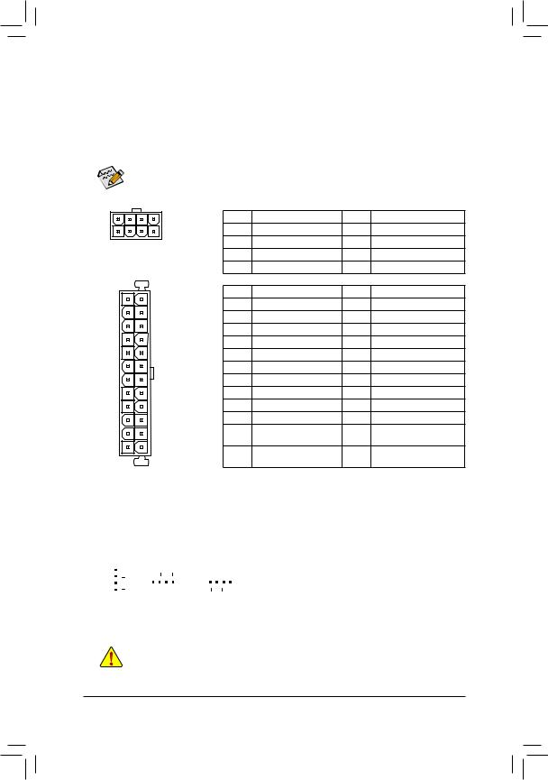
1/2) ATX_12V_2X4/ATX (2×4 12V Power Connector and 2×12 Main Power Connector)
With the use of the power connector, the power supply can supply enough stable power to all the components on the motherboard. Before connecting the power connector, first make sure the power supply is turned off and all devices are properly installed. The power connector possesses a foolproof design. Connect the power supply cable to the power connector in the correct orientation.
The 12V power connector mainly supplies power to the CPU. If the 12V power connector is not connected, the computer will not start.
To meet expansion requirements, it is recommended that a power supply that can withstand high power consumption be used (500W or greater). If a power supply is used that does not provide the required power, the result can lead to an unstable or unbootable system.
|
ATX_12V_2X4: |
||||||
|
5 |
8 |
Pin No. |
Definition |
Pin No. |
Definition |
|
|
1 |
4 |
1 |
GND (Only for 2×4-pin 12V) |
5 |
+12V (Only for 2×4-pin 12V) |
|
|
ATX_12V_2X4 |
2 |
GND (Only for 2×4-pin 12V) |
6 |
+12V (Only for 2×4-pin 12V) |
||
|
3 |
GND |
7 |
+12V |
|||
|
4 |
GND |
8 |
+12V |
|||
|
ATX: |
||||||
|
12 |
24 |
Pin No. |
Definition |
Pin No. |
Definition |
|
|
1 |
3.3V |
13 |
3.3V |
|||
|
2 |
3.3V |
14 |
-12V |
|||
|
3 |
GND |
15 |
GND |
|||
|
4 |
+5V |
16 |
PS_ON (soft On/Off) |
|||
|
5 |
GND |
17 |
GND |
|||
|
6 |
+5V |
18 |
GND |
|||
|
7 |
GND |
19 |
GND |
|||
|
8 |
Power Good |
20 |
NC |
|||
|
9 |
5VSB (stand by +5V) |
21 |
+5V |
|||
|
10 |
+12V |
22 |
+5V |
|||
|
11 |
+12V (Only for 2×12-pin |
23 |
+5V (Only for 2×12-pin ATX) |
|||
|
1 |
13 |
ATX) |
||||
|
12 |
3.3V (Only for 2×12-pin |
24 |
GND (Only for 2×12-pin ATX) |
|||
|
ATX) |
||||||
|
ATX |
3/4) CPU_FAN/SYS_FAN1/2 (Fan Headers)
All fan headers on this motherboard are 4-pin. Most fan headers possess a foolproof insertion design. When connecting a fan cable, be sure to connect it in the correct orientation (the black connector wire is the ground wire). The speed control function requires the use of a fan with fan speed control design. For optimum heat dissipation, it is recommended that a system fan be installed inside the chassis.
|
Pin No. |
Definition |
|||||||||||||
|
1 |
1 |
1 |
1 |
GND |
||||||||||
|
2 |
Voltage Speed Control |
|||||||||||||
|
CPU_FAN |
SYS_FAN1 |
SYS_FAN2 |
||||||||||||
|
3 |
Sense |
|||||||||||||
|
4 |
PWM Speed Control |
•• Be sure to connect fan cables to the fan headers to prevent your CPU and system from overheating. Overheating may result in damage to the CPU or the system may hang.
•• Thesefanheadersarenotconfigurationjumperblocks.Donotplaceajumpercapontheheaders.
— 13 —
5)SYS_FAN3_PUMP (System Fan/Water Cooling Pump Header)
The pump header is 4-pin and possesses a foolproof insertion design. Most fan headers possess a foolproof insertion design. When connecting a fan cable, be sure to connect it in the correct orientation (the black connector wire is the ground wire). The speed control function requires the use of a fan with fan speed control design. For optimum heat dissipation, it is recommended that a system fan be installed inside the chassis.
The header also provides speed control for a water cooling pump, refer to Chapter 2, «BIOS Setup,» «M.I.T.,» for more information
|
Pin No. |
Definition |
||
|
1 |
1 |
GND |
|
|
2 |
Voltage Speed Control |
||
|
3 |
Sense |
||
|
4 |
PWM Speed Control |
6) SATA3 0/1/2/3/4/5 (SATA 6Gb/s Connectors)
The SATA connectors conform to SATA 6Gb/s standard and are compatible with SATA 3Gb/s and SATA 1.5Gb/s standard. Each SATA connector supports a single SATA device. The Intel® ChipsetsupportsRAID0, RAID 1, RAID 5, and RAID 10. Refer to Chapter 3, «Configuring a RAID Set,» for instructions on configuring a RAID array.
|
1 |
1 |
Pin No. |
Definition |
||||
|
SATA3 |
5 |
1 |
GND |
||||
|
4 |
2 |
TXP |
|||||
|
SATA3 |
1 |
0 |
|||||
|
3 |
TXN |
||||||
|
3 |
2 |
7 |
1 |
||||
|
7 |
1 |
4 |
GND |
||||
|
5 |
RXN |
||||||
|
6 |
RXP |
||||||
|
7 |
7 |
7 |
GND |
||||

 To enable hot-plugging for the SATA ports, refer to Chapter 2, «BIOS Setup,» «PeripheralsSATA
  And RST Configuration,» for more information.
7)M2P_32G (M.2 Socket 3 Connector)
The M.2 connector supports M.2 SATASSDs and M.2 PCIe SSDs and support RAID configuration through the Intel® Chipset. Please note that an M.2 PCIe SSD cannot be used to create a RAID set either with an M.2 SATA SSD or a SATA hard drive and can only be used to build a RAID set with UEFI. Refer to Chapter 3, «Configuring a RAID Set,» for instructions on configuring a RAID array.
Follow the steps below to correctly install an M.2 SSD in the M.2 connector. Step 1:
Use a screw driver to unfasten the screw and nut from the motherboard. Locate the proper mounting hole for the M.2 SSD to be installed and then screw the nut first.
Step 2:
Slide the M.2 SSD into the connector at an angle. Step 3:
Press the M.2 SSD down and then secure it with the screw.

 Select the proper hole for the M.2 SSD to be installed and refasten the screw and nut. — 14 —
 Loading…

To reduce the impacts on global warming, the packaging materials of this product
are recyclable and reusable. GIGABYTE works with you to protect the environment.
For more product details, please visit GIGABYTE’s website.
GA-Z270P-D3
User’s Manual
Rev. 1001
12ME-Z270PD3-1001R
Copyright
© 2016 GIGA-BYTE TECHNOLOGY CO., LTD. All rights reserved.
The trademarks mentioned in this manual are legally registered to their respective owners.
Disclaimer
Information in this manual is protected by copyright laws and is the property of GIGABYTE.
Changes to the specications and features in this manual may be made by GIGABYTE without prior notice.
No part of this manual may be reproduced, copied, translated, transmitted, or published in any form or
by any means without GIGABYTE’s prior written permission.
In order to assist in the use of this product, carefully read the User’s Manual.
For product-related information, check on our website at: http://www.gigabyte.com
Identifying Your Motherboard Revision
The revision number on your motherboard looks like this: «REV: X.X.» For example, «REV: 1.0″ means
the revision of the motherboard is 1.0. Check your motherboard revision before updating motherboard
BIOS, drivers, or when looking for technical information.
Example:
Motherboard
GA-Z270P-D3
Dec. 7, 2016
Dec. 7, 2016
Motherboard
GA-Z270P-D3

— 3 —
Table of Contents
GA-Z270P-D3 Motherboard Layout ………………………………………………………………………4
Chapter 1 Hardware Installation ………………………………………………………………………….5
1-1 Installation Precautions ………………………………………………………………………… 5
1-2 ProductSpecications ………………………………………………………………………….. 6
1-3 Installing the CPU ……………………………………………………………………………….. 9
1-4 Installing the Memory …………………………………………………………………………… 9
1-5 Installing an Expansion Card ………………………………………………………………. 10
1-6 Back Panel Connectors ………………………………………………………………………. 10
1-7 Internal Connectors ……………………………………………………………………………. 12
Chapter 2 BIOS Setup ……………………………………………………………………………………..19
2-1 Startup Screen ………………………………………………………………………………….. 19
2-2 M.I.T. ……………………………………………………………………………………………….. 20
2-3 System …………………………………………………………………………………………….. 26
2-4 BIOS ………………………………………………………………………………………………… 27
2-5 Peripherals ……………………………………………………………………………………….. 30
2-6 Chipset …………………………………………………………………………………………….. 33
2-7 Power ………………………………………………………………………………………………. 34
2-8 Save & Exit ……………………………………………………………………………………….. 36
Chapter 3 Appendix …………………………………………………………………………………………37
3-1 ConguringaRAIDSet ………………………………………………………………………. 37
3-2 Drivers Installation ……………………………………………………………………………… 40
RegulatoryStatements …………………………………………………………………………………. 41
Contact Us …………………………………………………………………………………………………. 44
— 4 —
GA-Z270P-D3 Motherboard Layout
Box Contents
5GA-Z270P-D3 motherboard 5Two SATA cables
5Motherboard driver disk 5I/O Shield
5User’s Manual 5One G Connector
* The box contents above are for reference only and the actual items shall depend on the product package you obtain.
The box contents are subject to change without notice.
KB_MS
HDMI
R_USB30_2
USB_LAN
LGA1151
ATX
AUDIO
DDR4_4
DDR4_2
DDR4_3
DDR4_1
ATX_12V_2X4
Intel® Z270
CLR_CMOS
M_BIOS
B_BIOS
PCIEX1_1
PCIEX4_1
PCIEX16
PCIEX1_2
PCIEX1_3
F_USB30
SYS_FAN2
M2P_32G
CODEC
GA-Z270P-D3
F_PANELF_USB1F_USB2TPMCOM
SPDIF_O
F_AUDIO SYS_FAN3_PUMP
SYS_FAN1
CPU_FAN
iTE®
Super I/O
426080
SATA3
5
4
1 0
3 2
BAT
R_USB30_1
SATA3
Realtek®
GbE LAN
PCIEX4_2

Chapter 1 Hardware Installation
1-1 Installation Precautions
The motherboard contains numerous delicate electronic circuits and components which can become
damaged as a result of electrostatic discharge (ESD). Prior to installation, carefully read the user’s
manual and follow these procedures:
•Prior to installation, make sure the chassis is suitable for the motherboard.
•Prior to installation, do not remove or break motherboard S/N (Serial Number) sticker or
warranty sticker provided by your dealer. These stickers are required for warranty validation.
•Always remove the AC power by unplugging the power cord from the power outlet before
installing or removing the motherboard or other hardware components.
•When connecting hardware components to the internal connectors on the motherboard, make
sure they are connected tightly and securely.
•When handling the motherboard, avoid touching any metal leads or connectors.
•It is best to wear an electrostatic discharge (ESD) wrist strap when handling electronic
components such as a motherboard, CPU or memory. If you do not have an ESD wrist strap,
keepyourhandsdryandrsttouchametalobjecttoeliminatestaticelectricity.
•Prior to installing the motherboard, please have it on top of an antistatic pad or within an
electrostatic shielding container.
•Before connecting or unplugging the power supply cable from the motherboard, make sure
the power supply has been turned off.
•Before turning on the power, make sure the power supply voltage has been set according to
the local voltage standard.
•Before using the product, please verify that all cables and power connectors of your hardware
components are connected.
•To prevent damage to the motherboard, do not allow screws to come in contact with the
motherboard circuit or its components.
•Make sure there are no leftover screws or metal components placed on the motherboard or
within the computer casing.
•Do not place the computer system on an uneven surface.
•Do not place the computer system in a high-temperature or wet environment.
•Turning on the computer power during the installation process can lead to damage to system
components as well as physical harm to the user.
•If you are uncertain about any installation steps or have a problem related to the use of the
product,pleaseconsultacertiedcomputertechnician.
•If you use an adapter, extension power cable, or power strip, ensure to consult with its installation
and/or grounding instructions.
— 5 —
1-2 ProductSpecications
CPU Support for 7th and 6th generation Intel® Core™ i7 processors/
Intel® Core™ i5 processors/Intel® Core™ i3 processors/
Intel® Pentium® processors/Intel® Celeron® processors in the LGA1151 package
(Go to GIGABYTE’s website for the latest CPU support list.)
L3 cache varies with CPU
Chipset Intel® Z270 Express Chipset
Memory 4xDDR4DIMMsocketssupportingupto64GBofsystemmemory
* Due to a Windows 32-bit operating system limitation, when more than 4 GB of physical
memory is installed, the actual memory size displayed will be less than the size of
the physical memory installed.
Dual channel memory architecture
SupportforDDR42400/2133MHzmemorymodules
SupportforECCUn-bufferedDIMM 1Rx8/2Rx8 memory modules (operate in
non-ECC mode)
Supportfornon-ECCUn-bufferedDIMM1Rx8/2Rx8/1Rx16memorymodules
SupportforExtremeMemoryProle(XMP)memorymodules
(Go to GIGABYTE’s website for the latest supported memory speeds and memory
modules.)
Onboard
Graphics
Integrated Graphics Processor-Intel® HD Graphics support:
— 1 x HDMI port, supporting a maximum resolution of 4096×2160@24 Hz
* Support for HDMI 1.4 version.
Maximum shared memory of 1 GB
Audio Realtek® ALC887 codec
HighDenitionAudio
2/4/5.1/7.1-channel
Support for S/PDIF Out
LAN Realtek® GbE LAN chip (10/100/1000 Mbit)
Expansion Slots 1 x PCI Express x16 slot, running at x16 (PCIEX16)
* For optimum performance, if only one PCI Express graphics card is to be installed,
be sure to install it in the PCIEX16 slot.
2 x PCI Express x16 slots, running at x4 (PCIEX4_1/PCIEX4_2)
3 x PCI Express x1 slots
(All of the PCI Express slots conform to PCI Express 3.0 standard.)
Multi-Graphics
Technology
Support for AMD Quad-GPU CrossFireX™ and 2-Way AMD CrossFire™
technologies (PCIEX16 and PCIEX4)
Storage Interface Chipset:
— 1 x M.2 connector (Socket 3, M key, type 2242/2260/2280 SATA and PCIe
x4/x2 SSD support)
— 6 x SATA 6Gb/s connectors
- SupportforRAID0,RAID1,RAID5,andRAID10
* Referto»1-7InternalConnectors,»fortheinstallationnoticesfortheM.2andSATA
connectors.
— 6 —
USB Chipset:
— 6 x USB 3.1 Gen 1 ports (4 ports on the back panel, 2 ports available through
the internal USB header)
— 6 x USB 2.0/1.1 ports (2 ports on the back panel, 4 ports available through
the internal USB headers)
Internal
Connectors
1 x 24-pin ATX main power connector
1 x 8-pin ATX 12V power connector
1 x CPU fan header
2 x system fan headers
1 x system fan/water cooling pump header
6 x SATA 6Gb/s connectors
1 x M.2 Socket 3 connector
1 x front panel header
1 x front panel audio header
1 x S/PDIF Out header
1 x USB 3.1 Gen 1 header
2 x USB 2.0/1.1 headers
1 x Trusted Platform Module (TPM) header
1 x serial port header
1 x Clear CMOS jumper
Back Panel
Connectors
1 x PS/2 mouse port
1 x PS/2 Keyboard port
1 x HDMI port
4 x USB 3.1 Gen 1 ports
2 x USB 2.0/1.1 ports
1xRJ-45port
3 x audio jacks (Line In, Line Out, Mic In)
I/O Controller iTE® I/O Controller Chip
Hardware
Monitor
Voltage detection
Temperature detection
Fan speed detection
Overheating warning
Fan fail warning
Fan speed control
* Whether the fan (pump) speed control function is supported will depend on the fan
(pump) you install.
BIOS 2x64Mbitash
Use of licensed AMI UEFI BIOS
Support for DualBIOS™
PnP 1.0a, DMI 2.7, WfM 2.0, SM BIOS 2.7, ACPI 5.0
— 7 —
Unique Features Support for APP Center
* Available applications in APP Center may vary by motherboard model. Supported
functionsofeachapplicationmayalsovarydependingonmotherboardspecications.
— 3D OSD
— @BIOS
— Ambient LED
— AutoGreen
— BIOS Setup
— Color Temperature
— Cloud Station
— EasyTune
- EasyRAID
— Fast Boot
— Game Boost
— ON/OFF Charge
— Platform Power Management
— Smart Backup
— Smart Keyboard
— Smart TimeLock
— System Information Viewer
— USB Blocker
— V-Tuner
Support for 3TB+ Unlock
Support for Q-Flash
Support for Xpress Install
Bundled
Software
Norton® Internet Security (OEM version)
Intel® Optane™MemoryReady
cFosSpeed
Operating
System
Support for Windows 10/8.1 64-bit
Support for Windows 7 32-bit/64-bit
* Operating systems supported may vary depending on your processor
model.
* Pleasedownloadthe»WindowsUSBInstallationTool»fromGIGABYTE’s
website and install it before installing Windows 7.
Form Factor ATX Form Factor; 30.5cm x 19.9cm
* GIGABYTEreservestherighttomakeanychangestotheproductspecicationsandproduct-relatedinformationwithout
prior notice.
Please visit GIGABYTE’s website
for support lists of CPU, memory
modules, SSDs, and M.2 devices.
Please visit the SupportUtility List
page on GIGABYTE’s website to
download the latest version of apps.
— 8 —
1-3 Installing the CPU
ReadthefollowingguidelinesbeforeyoubegintoinstalltheCPU:
•Make sure that the motherboard supports the CPU.
(Go to GIGABYTE’s website for the latest CPU support list.)
•Always turn off the computer and unplug the power cord from the power outlet before installing the
CPU to prevent hardware damage.
•Locate the pin one of the CPU. The CPU cannot be inserted if oriented incorrectly. (Or you may
locate the notches on both sides of the CPU and alignment keys on the CPU socket.)
•Apply an even and thin layer of thermal grease on the surface of the CPU.
•Do not turn on the computer if the CPU cooler is not installed, otherwise overheating and damage
of the CPU may occur.
•SettheCPUhostfrequencyinaccordancewiththeCPUspecications.Itisnotrecommended
thatthesystembusfrequencybesetbeyondhardwarespecicationssinceitdoesnotmeetthe
standard requirements for the peripherals. If you wish to set the frequency beyond the standard
specications,pleasedosoaccordingtoyourhardwarespecicationsincludingtheCPU,graphics
card, memory, hard drive, etc.
Installing the CPU
Locate the alignment keys on the motherboard CPU socket and the notches on the CPU.
Do not remove the CPU socket cover before inserting the CPU. It may pop off from the load
plate automatically during the process of re—engaging the lever after you insert the CPU.
1-4 Installing the Memory
Readthefollowingguidelinesbeforeyoubegintoinstallthememory:
•Make sure that the motherboard supports the memory. It is recommended that memory of the same
capacity, brand, speed, and chips be used.
(Go to GIGABYTE’s website for the latest supported memory speeds and memory modules.)
•Always turn off the computer and unplug the power cord from the power outlet before installing the
memory to prevent hardware damage.
•Memory modules have a foolproof design. A memory module can be installed in only one direction.
If you are unable to insert the memory, switch the direction.
Alignment
Key
Alignment
Key
LGA1151 CPU Socket
Pin One Corner of the CPU Socket
DualChannelMemoryConguration
This motherboard provides four memory sockets and supports Dual Channel Technology. After the memory
isinstalled,theBIOSwillautomaticallydetectthespecicationsandcapacityofthememory.EnablingDual
Channel memory mode will double the original memory bandwidth.
LGA1151 CPU
Triangle Pin One Marking on the CPU
Notch
Notch
Please visit GIGABYTE’s website for details on hardware installation.
— 9 —
1-5 Installing an Expansion Card
Readthefollowingguidelinesbeforeyoubegintoinstallanexpansioncard:
•Make sure the motherboard supports the expansion card. Carefully read the manual that came
with your expansion card.
•Always turn off the computer and unplug the power cord from the power outlet before installing an
expansion card to prevent hardware damage.
Due to CPU limitations, read the following guidelines before installing the memory in Dual Channel mode.
1. Dual Channel mode cannot be enabled if only one memory module is installed.
2. When enabling Dual Channel mode with two or four memory modules, it is recommended that memory
of the same capacity, brand, speed, and chips be used and installed in the same colored sockets.
The four memory sockets are divided into two channels and each channel has two memory sockets as following:
ChannelA:DDR4_2,DDR4_4
ChannelB:DDR4_1,DDR4_3
DualChannelMemoryCongurationsTable
DDR4_4 DDR4_2 DDR4_3 DDR4_1
2 Modules — — DS/SS — — DS/SS
DS/SS — — DS/SS — —
4 Modules DS/SS DS/SS DS/SS DS/SS
(SS=Single-Sided,DS=Double-Sided,»--«=NoMemory)
1-6 Back Panel Connectors
PS/2 Keyboard and PS/2 Mouse Port
Use the upper port (green) to connect a PS/2 mouse and the lower port (purple) to connect a PS/2 keyboard.
HDMI Port
The HDMI port is HDCP compliant and supports Dolby TrueHD and DTS HD
Master Audio formats. It also supports up to 192 KHz/16bit 8-channel LPCM
audio output. You can use this port to connect your HDMI-supported monitor. The maximum supported
resolution is 4096×2160@24 Hz, but the actual resolutions supported are dependent on the monitor
being used.
After installing the HDMI device, make sure to set the default sound playback device to HDMI. (The
item name may differ depending on your operating system.)
— 10 —
USB 3.1 Gen 1 Port
TheUSB3.1Gen1portsupportstheUSB3.1Gen1specicationandiscompatibletotheUSB2.0
specication.UsethisportforUSBdevices.
RJ-45 LAN Port
The Gigabit Ethernet LAN port provides Internet connection at up to 1 Gbps data rate. The following
describes the states of the LAN port LEDs.
USB 2.0/1.1 Port
TheUSBportsupportstheUSB2.0/1.1specication.UsethisportforUSBdevices.
Line In (Blue)
The line in jack. Use this audio jack for line in devices such as an optical drive, walkman, etc.
Line Out (Green)
The line out jack. Use this audio jack for a headphone or 2-channel speaker. This jack can be used to
connectfrontspeakersina4/5.1/7.1-channelaudioconguration.
Mic In (Pink)
The Mic in jack.
•Whenremovingthecableconnectedtoabackpanelconnector,rstremovethecablefromyour
device and then remove it from the motherboard.
•When removing the cable, pull it straight out from the connector. Do not rock it side to side to
prevent an electrical short inside the cable connector.
Tocongure7.1-channelaudio,youhavetouseanHDfrontpanelaudiomoduleandenablethe
multi-channel audio feature through the audio driver. Please visit GIGABYTE’s website for more
software information.
Activity LED
Connection/
Speed LED
LAN Port
Activity LED:Connection/Speed LED:
State Description
Orange 1 Gbps data rate
Green 100 Mbps data rate
Off 10 Mbps data rate
State Description
Blinking Data transmission or receiving is occurring
Off No data transmission or receiving is occurring
— 11 —
Readthefollowingguidelinesbeforeconnectingexternaldevices:
•First make sure your devices are compliant with the connectors you wish to connect.
•Before installing the devices, be sure to turn off the devices and your computer. Unplug the power
cord from the power outlet to prevent damage to the devices.
•After installing the device and before turning on the computer, make sure the device cable has
been securely attached to the connector on the motherboard.
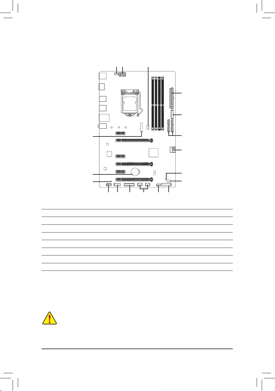
1-7 Internal Connectors
1) ATX_12V_2X4
2) ATX
3) CPU_FAN
4) SYS_FAN1/2
5) SYS_FAN3_PUMP
6) SATA3 0/1/2/3/4/5
7) M2 P_ 32G
 F_PANEL
9) F_AUDIO
10) SPDIF_O
11) F_USB30
12) F_USB1/F_USB2
13) TPM
14) COM
15) BAT
16) CLR_CMOS
5 8
6
2
11
139
1
4
14
16
4
7
12
3
6
10
15
— 12 —
131
2412
ATX
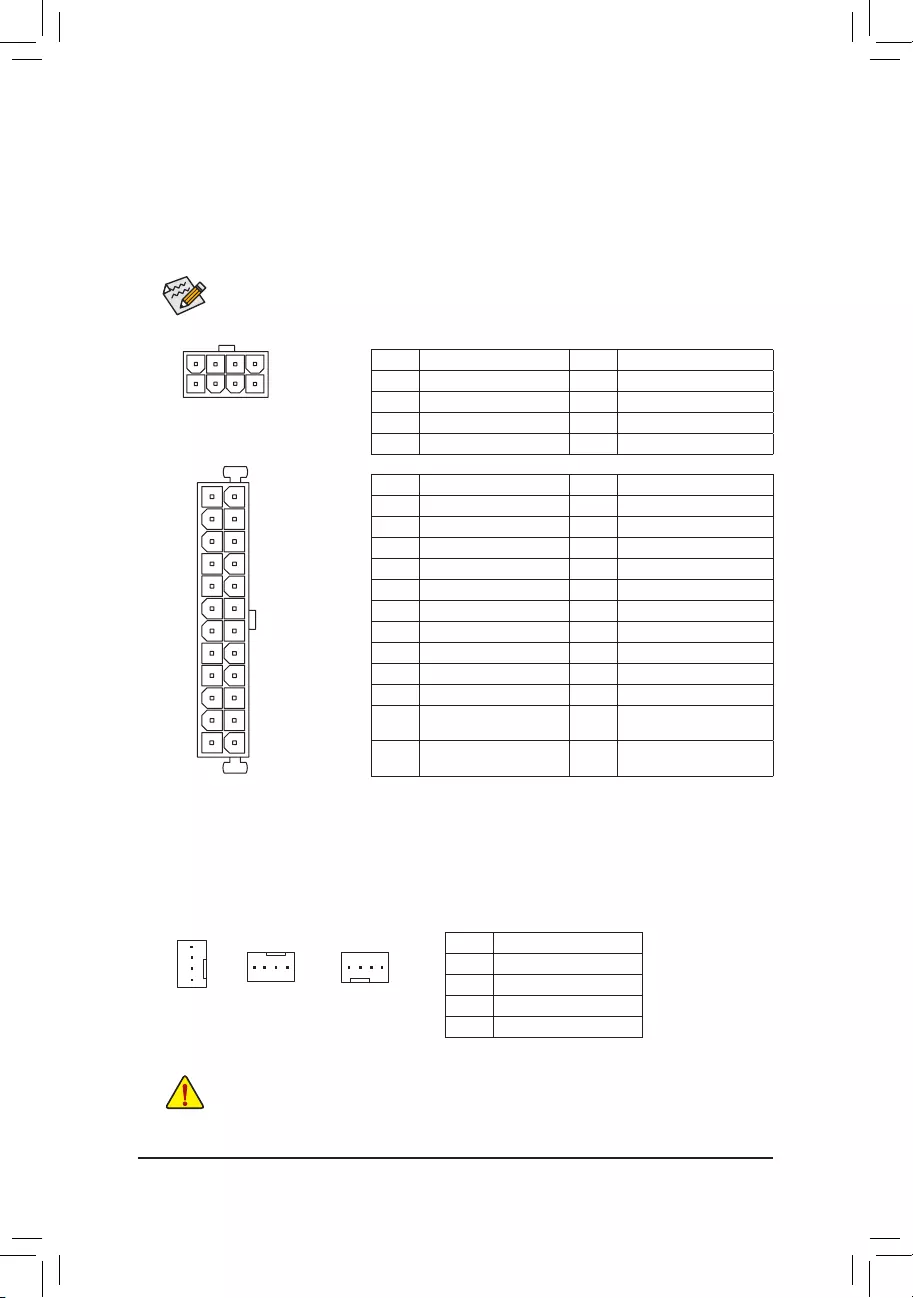
1/2) ATX_12V_2X4/ATX (2×4 12V Power Connector and 2×12 Main Power Connector)
With the use of the power connector, the power supply can supply enough stable power to all the components
onthemotherboard.Beforeconnectingthepowerconnector,rstmakesurethepowersupplyisturned
off and all devices are properly installed. The power connector possesses a foolproof design. Connect the
power supply cable to the power connector in the correct orientation.
The 12V power connector mainly supplies power to the CPU. If the 12V power connector is not connected,
the computer will not start.
To meet expansion requirements, it is recommended that a power supply that can withstand high
power consumption be used (500W or greater). If a power supply is used that does not provide the
required power, the result can lead to an unstable or unbootable system.
ATX:
Pin No. Denition Pin No. Denition
1 3.3V 13 3.3V
2 3.3V 14 -12V
3 GND 15 GND
4 +5V 16 PS_ON (soft On/Off)
5 GND 17 GND
6 +5V 18 GND
7 GND 19 GND
8 Power Good 20 NC
9 5VSB (stand by +5V) 21 +5V
10 +12V 22 +5V
11 +12V (Only for 2×12-pin
ATX)
23 +5V (Only for 2×12-pin ATX)
12 3.3V (Only for 2×12-pin
ATX)
24 GND (Only for 2×12-pin ATX)
ATX_12V_2X4:
Pin No. Denition Pin No. Denition
1GND (Only for 2×4-pin 12V) 5 +12V (Only for 2×4-pin 12V)
2GND (Only for 2×4-pin 12V) 6 +12V (Only for 2×4-pin 12V)
3 GND 7 +12V
4 GND 8 +12V
3/4) CPU_FAN/SYS_FAN1/2 (Fan Headers)
All fan headers on this motherboard are 4-pin. Most fan headers possess a foolproof insertion design.
When connecting a fan cable, be sure to connect it in the correct orientation (the black connector wire is
the ground wire). The speed control function requires the use of a fan with fan speed control design. For
optimum heat dissipation, it is recommended that a system fan be installed inside the chassis.
•Be sure to connect fan cables to the fan headers to prevent your CPU and system from
overheating. Overheating may result in damage to the CPU or the system may hang.
•Thesefanheadersarenotcongurationjumperblocks.Donotplaceajumpercapontheheaders.
ATX_12V_2X4
41
85
Pin No. Denition
1 GND
2 Voltage Speed Control
3 Sense
4 PWM Speed Control
CPU_FAN
SYS_FAN2
1
SYS_FAN1
1
1
— 13 —
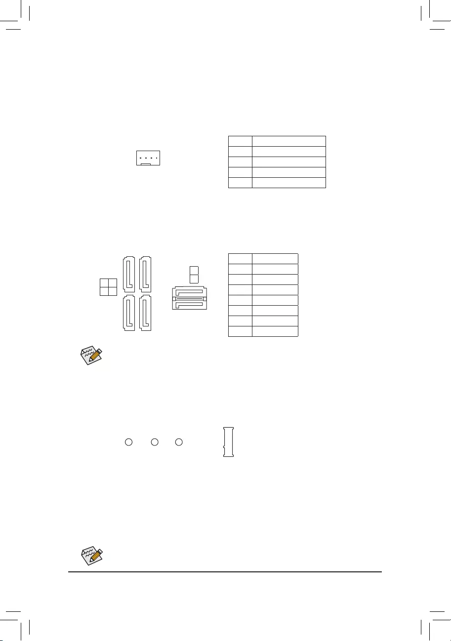
6) SATA3 0/1/2/3/4/5 (SATA 6Gb/s Connectors)
The SATA connectors conform to SATA 6Gb/s standard and are compatible with SATA 3Gb/s and SATA
1.5Gb/s standard. Each SATA connector supports a single SATA device. The Intel®ChipsetsupportsRAID0,
RAID1,RAID5,andRAID10.RefertoChapter3,»ConguringaRAIDSet,»forinstructionsonconguring
aRAIDarray.
Pin No. Denition
1 GND
2 TXP
3 TXN
4 GND
5RXN
6RXP
7 GND
Toenablehot-pluggingfortheSATAports,refertoChapter2,«BIOSSetup,»«PeripheralsSATA
AndRSTConguration,»formoreinformation.
1
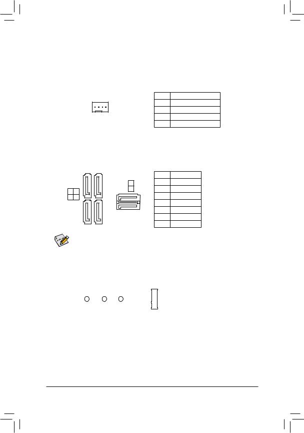
5) SYS_FAN3_PUMP (System Fan/Water Cooling Pump Header)
The pump header is 4-pin and possesses a foolproof insertion design. Most fan headers possess a foolproof
insertion design. When connecting a fan cable, be sure to connect it in the correct orientation (the black
connector wire is the ground wire). The speed control function requires the use of a fan with fan speed control
design. For optimum heat dissipation, it is recommended that a system fan be installed inside the chassis.
Theheaderalsoprovidesspeedcontrolforawatercoolingpump,refertoChapter2,»BIOSSetup,»«M.I.T.,»
for more information
Pin No. Denition
1 GND
2 Voltage Speed Control
3 Sense
4 PWM Speed Control
SATA3 1 0
3 2
SATA3
77
11
1
1
7
7
5
4
7) M2P_32G (M.2 Socket 3 Connector)
TheM.2connectorsupportsM.2SATASSDsandM.2PCIeSSDsandsupportRAIDcongurationthrough
the Intel® Chipset. PleasenotethatanM.2PCIeSSDcannotbeusedtocreateaRAIDseteitherwith
anM.2SATASSDoraSATAharddriveandcanonlybeusedtobuildaRAIDsetwithUEFI.Refer
toChapter3,»ConguringaRAIDSet,»forinstructionsonconguringaRAIDarray.
Follow the steps below to correctly install an M.2 SSD in the M.2 connector.
Step 1:
Use a screw driver to unfasten the screw and nut from the motherboard. Locate the proper mounting hole for
theM.2SSDtobeinstalledandthenscrewthenutrst.
Step 2:
Slide the M.2 SSD into the connector at an angle.
Step 3:
Press the M.2 SSD down and then secure it with the screw.
Select the proper hole for the M.2 SSD to be installed and refasten the screw and nut.
F_USB30 F_U
B_
F_ F_
_
B
BS_
B
SB_
B
_S
S_
_
B
_U
_
B
S
123
123
123
123
1
1
1
1
BSS
S
_S
SSU
1 2 3
S3 BSSS
U
__ 3
F_USB3F
S _
S _
S _
SF
B_
B_
F
_0
S
S
_0F
_F
_
_
__B
U
S _S
_
USB0_B
B_
80 60 42
— 14 —
SATA3 0 SATA3 1 SATA3 2 SATA3 3 SATA3 4 SATA3 5
M.2 SATA SSD r a a a a a
M.2 PCIe x4 SSD
aaaaaa
M.2 PCIe x2 SSD
aaaaaa
No M.2 SSD Installed aaaaaa
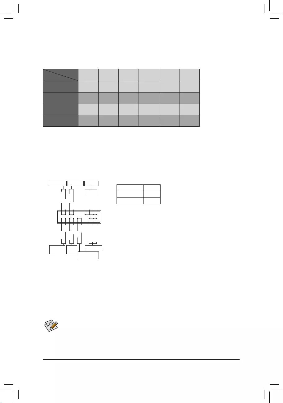
a: Available r: Not available
Connector
Type of
M.2 SSD
Installation Notices for the M.2, and SATA Connectors:
Due to the limited number of lanes provided by the Chipset, the availability of the SATA connectors may be
affected by the type of device installed in the M2P_32G connector. The M2P_32G connector shares bandwidth
withtheSATA30connector.Refertothefollowingtablefordetails.
The front panel design may differ by chassis. A front panel module mainly consists of power switch, reset
switch, power LED, hard drive activity LED, speaker and etc. When connecting your chassis front panel
module to this header, make sure the wire assignments and the pin assignments are matched correctly.
F_PANEL (Front Panel Header)
Connect the power switch, reset switch, speaker, chassis intrusion switch/sensor and system status indicator
on the chassis to this header according to the pin assignments below. Note the positive and negative pins
before connecting the cables.
System Status LED
S0 On
S3/S4/S5 Off
•PW(PowerSwitch,Red):
Connects to the power switch on the chassis front panel. You may
congurethewaytoturnoffyoursystemusingthepowerswitch(refer
toChapter2,»BIOSSetup,»»Power,»formoreinformation).
•SPEAK (Speaker, Orange):
Connects to the speaker on the chassis front panel. The system reports
system startup status by issuing a beep code. One single short beep
will be heard if no problem is detected at system startup.
•PLED/PWR_LED (Power LED, Yellow/Purple):
Connects to the power status indicator
on the chassis front panel. The LED is on
when the system is operating. The LED is
off when the system is in S3/S4 sleep state
or powered off (S5).
•HD (Hard Drive Activity LED, Blue):
Connects to the hard drive activity LED on the chassis front panel. The LED is on when the hard drive is
reading or writing data.
•RES (ResetSwitch,Green):
Connects to the reset switch on the chassis front panel. Press the reset switch to restart the computer if the
computer freezes and fails to perform a normal restart.
•CI (Chassis Intrusion Header, Gray):
Connects to the chassis intrusion switch/sensor on the chassis that can detect if the chassis cover has been
removed. This function requires a chassis with a chassis intrusion switch/sensor.
•NC (Orange): No Connection.
Power LED
1
2
19
20
CI-
CI+
PWR_LED-
PWR_LED+
PLED-
PW-
SPEAK+
SPEAK-
PLED+
PW+
Power LED
HD-
RES+
HD+
RES-
Hard Drive
Activity LED
Reset
Switch Chassis Intrusion
Header
Power Switch Speaker
PWR_LED-
NC
NC
— 15 —
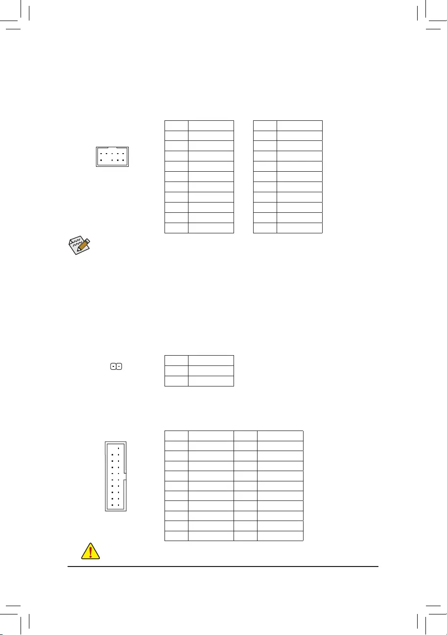
9) F_AUDIO (Front Panel Audio Header)
ThefrontpanelaudioheadersupportsIntelHighDenitionaudio(HD)andAC’97audio.Youmayconnect
your chassis front panel audio module to this header. Make sure the wire assignments of the module
connector match the pin assignments of the motherboard header. Incorrect connection between the module
connector and the motherboard header will make the device unable to work or even damage it.
For HD Front Panel Audio: For AC’97 Front Panel Audio:
•The front panel audio header supports HD audio by default.
•Audio signals will be present on both of the front and back panel audio connections simultaneously.
•Some chassis provide a front panel audio module that has separated connectors on each wire instead
of a single plug. For information about connecting the front panel audio module that has different
wire assignments, please contact the chassis manufacturer.
Pin No. Denition
1 MIC2_L
2 GND
3MIC2_R
4 NC
5LINE2_R
6 Sense
7FAUDIO_JD
8 No Pin
9 LINE2_L
10 Sense
Pin No. Denition
1 MIC
2 GND
3 MIC Power
4 NC
5LineOut(R)
6 NC
7 NC
8 No Pin
9 Line Out (L)
10 NC
F_USB30 F_U
B_
F_ F_
_
B
BS_
B
SB_
B
_S
S_
_
B
_U
_
B
S
123
123
123
123
1
1
1
1
BSS
S
_S
SSU
1 2 3
S3 BSSS
U
__ 3
F_USB3F
S _
S _
S _
SF
B_
B_
F
_0
S
S
_0F
_F
_
_
__B
U
S _S
_
USB0_B
B_
9 1
10 2
10) SPDIF_O (S/PDIF Out Header)
This header supports digital S/PDIF Out and connects a S/PDIF digital audio cable (provided by expansion
cards) for digital audio output from your motherboard to certain expansion cards like graphics cards and
sound cards. For example, some graphics cards may require you to use a S/PDIF digital audio cable for
digital audio output from your motherboard to your graphics card if you wish to connect an HDMI display
to the graphics card and have digital audio output from the HDMI display at the same time. For information
about connecting the S/PDIF digital audio cable, carefully read the manual for your expansion card.
Pin No. Denition
1 SPDIFO
2 GND
1
Pin No. Denition Pin No. Denition
1 VBUS 11 D2+
2SSRX1- 12 D2-
3SSRX1+ 13 GND
4 GND 14 SSTX2+
5 SSTX1- 15 SSTX2-
6 SSTX1+ 16 GND
7 GND 17 SSRX2+
8 D1- 18 SSRX2-
9 D1+ 19 VBUS
10 NC 20 No Pin
11) F_USB30 (USB 3.1 Gen 1 Header)
TheheaderconformstoUSB3.1Gen1andUSB2.0specicationandcanprovidetwoUSBports.For
purchasingtheoptional3.5″frontpanelthatprovidestwoUSB3.1Gen1ports,pleasecontactthelocal
dealer.
F_USB30 F_U
B_
F_ F_
_
B
BS_
B
SB_
B
_S
S_
_
B
_U
_
B
S
123
123
123
123
1
1
1
1
BSS
S
_S
SSU
1 2 3
S3 BSSS
U
__ 3
F_USB3F
S _
S _
S _
SF
B_
B_
F
_0
S
S
_0F
_F
_
_
__B
U
S _S
_
USB0_B
B_
10
20 1
11
Prior to installing the USB bracket, be sure to turn off your computer and unplug the power cord
from the power outlet to prevent damage to the USB bracket.
— 16 —
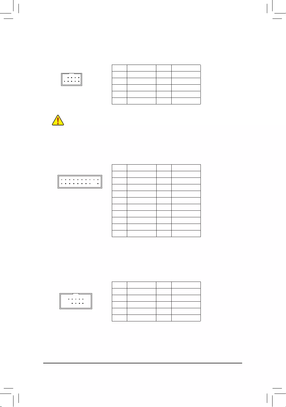
12) F_USB1/F_USB2 (USB 2.0/1.1 Headers)
TheheadersconformtoUSB2.0/1.1specication.EachUSBheadercanprovidetwoUSBportsviaan
optional USB bracket. For purchasing the optional USB bracket, please contact the local dealer.
Pin No. Denition Pin No. Denition
1 Power (5V) 6 USB DY+
2 Power (5V) 7 GND
3 USB DX- 8 GND
4 USB DY— 9 No Pin
5 USB DX+ 10 NC
•Do not plug the IEEE 1394 bracket (2×5-pin) cable into the USB 2.0/1.1 header.
•Prior to installing the USB bracket, be sure to turn off your computer and unplug the power cord
from the power outlet to prevent damage to the USB bracket.
10
9
2
1
20
19
2
1
F_USB30 F_U
B_
F_ F_
_
B
BS_
B
SB_
B
_S
S_
_
B
_U
_
B
S
123
123
123
123
1
1
1
1
BSS
S
_S
SSU
1 2 3
S3 BSSS
U
__ 3
F_USB3F
S _
S _
S _
SF
B_
B_
F
_0
S
S
_0F
_F
_
_
__B
U
S _S
_
USB0_B
B_
13) TPM (Trusted Platform Module Header)
You may connect a TPM (Trusted Platform Module) to this header.
Pin No. Denition Pin No. Denition
1 LCLK 11 LAD0
2 GND 12 GND
3LFRAME 13 NC
4 No Pin 14 NC
5LRESET 15 SB3V
6 NC 16 SERIRQ
7 LAD3 17 GND
8 LAD2 18 NC
9 VCC3 19 NC
10 LAD1 20 NC
Pin No. Denition Pin No. Denition
1 NDCD- 6 NDSR-
2 NSIN 7 NRTS-
3 NSOUT 8 NCTS-
4NDTR- 9NRI-
5 GND 10 No Pin
14) COM (Serial Port Header)
The COM header can provide one serial port via an optional COM port cable. For purchasing the optional
COM port cable, please contact the local dealer.
10
9
2
1
— 17 —
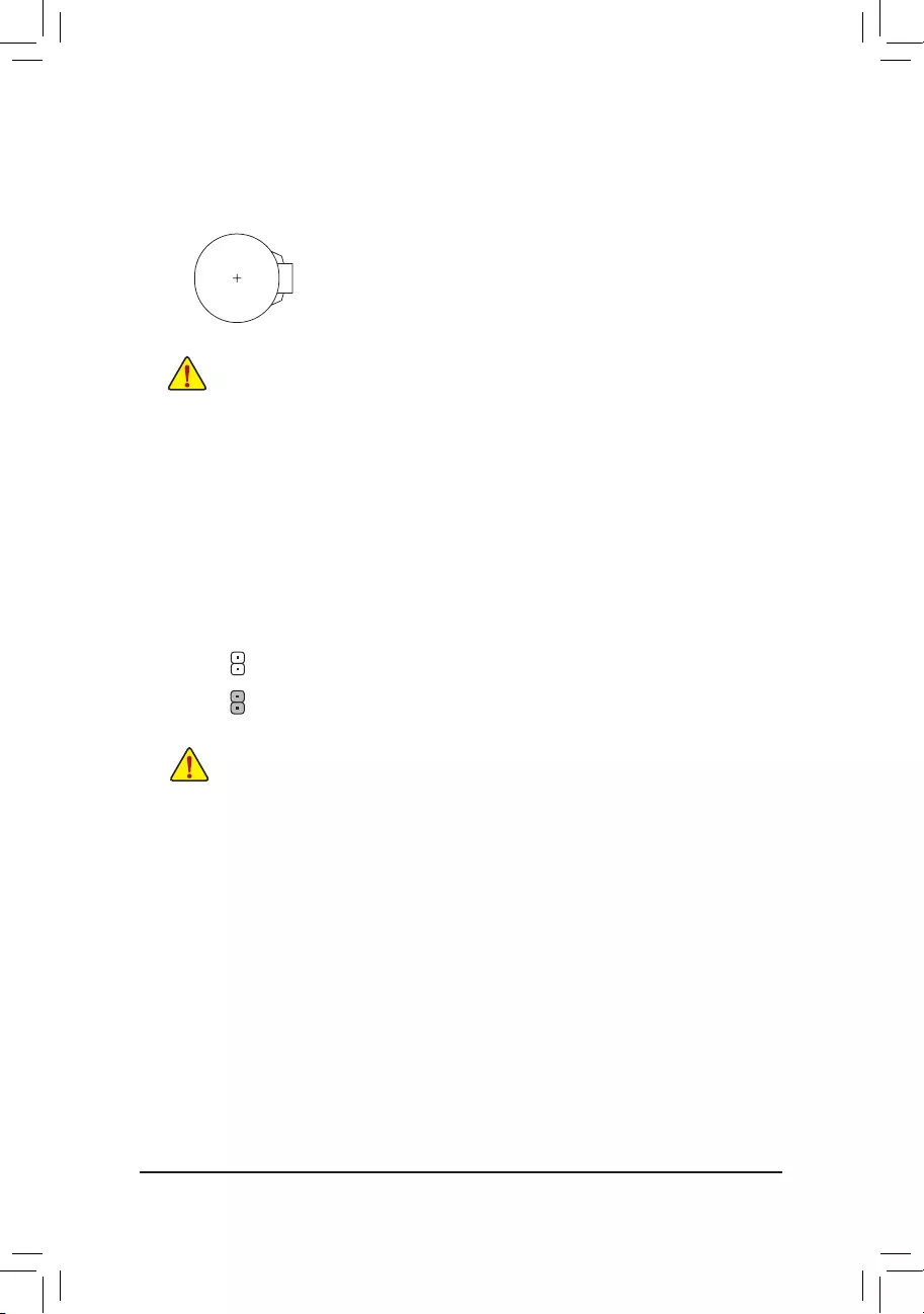
15) BAT (Battery)
Thebatteryprovidespowertokeepthevalues(suchasBIOScongurations,date,andtimeinformation)
intheCMOSwhenthecomputeristurnedoff.Replacethebatterywhenthebatteryvoltagedropstoalow
level, or the CMOS values may not be accurate or may be lost.
You may clear the CMOS values by removing the battery:
1. Turn off your computer and unplug the power cord.
2. Gently remove the battery from the battery holder and wait for one minute. (Or use a
metal object like a screwdriver to touch the positive and negative terminals of the battery
holder, making them short for 5 seconds.)
3. Replacethebattery.
4. Plug in the power cord and restart your computer.
•Always turn off your computer and unplug the power cord before replacing the battery.
•Replacethebatterywithanequivalentone.Dangerofexplosionifthebatteryisreplacedwith
an incorrect model.
•Contact the place of purchase or local dealer if you are not able to replace the battery by yourself
or uncertain about the battery model.
•When installing the battery, note the orientation of the positive side (+) and the negative side (-)
of the battery (the positive side should face up).
•Used batteries must be handled in accordance with local environmental regulations.
16) CLR_CMOS (Clear CMOS Jumper)
UsethisjumpertocleartheBIOScongurationandresettheCMOSvaluestofactorydefaults.Toclear
the CMOS values, use a metal object like a screwdriver to touch the two pins for a few seconds.
•Always turn off your computer and unplug the power cord from the power outlet before clearing
the CMOS values.
•After system restart, go to BIOS Setup to load factory defaults (select Load Optimized Defaults) or
manuallyconguretheBIOSsettings(refertoChapter2,«BIOSSetup,»forBIOScongurations).
Open: Normal
Short: Clear CMOS Values
— 18 —
•When the system is not stable as usual, select the Load Optimized Defaults item to set your system to its defaults.
•The BIOS Setup menus described in this chapter are for reference only and may differ by BIOS version.
BIOS (Basic Input and Output System) records hardware parameters of the system in the CMOS on the
motherboard. Its major functions include conducting the Power-On Self-Test (POST) during system startup,
saving system parameters and loading operating system, etc. BIOS includes a BIOS Setup program that allows
theusertomodifybasicsystemcongurationsettingsortoactivatecertainsystemfeatures.
When the power is turned off, the battery on the motherboard supplies the necessary power to the CMOS to
keepthecongurationvaluesintheCMOS.
To access the BIOS Setup program, press the <Delete> key during the POST when the power is turned on.
To upgrade the BIOS, use either the GIGABYTE Q-Flash or @BIOS utility.
•Q-Flash allows the user to quickly and easily upgrade or back up BIOS without entering the operating system.
•@BIOS is a Windows-based utility that searches and downloads the latest version of BIOS from the Internet
and updates the BIOS.
Chapter 2 BIOS Setup
•BecauseBIOSashingispotentiallyrisky,ifyoudonotencounterproblemsusingthecurrentversionofBIOS,
itisrecommendedthatyounotashtheBIOS.ToashtheBIOS,doitwithcaution.InadequateBIOSashing
may result in system malfunction.
•It is recommended that you not alter the default settings (unless you need to) to prevent system instability or other
unexpected results. Inadequately altering the settings may result in system’s failure to boot. If this occurs, try to
cleartheCMOSvaluesandresettheboardtodefaultvalues.(Refertothe»LoadOptimizedDefaults»sectionin
this chapter or introductions of the battery/clear CMOS jumper in Chapter 1 for how to clear the CMOS values.)
2-1 Startup Screen
The following startup Logo screen will appear when the computer boots.
(Sample BIOS Version: F1a)
Function Keys
There are two different BIOS modes as follows and you can use the <F2> key to switch between the two modes.
The Classic Setup mode provides detailed BIOS settings. You can press the arrow keys on your keyboard to move
among the items and press <Enter> to accept or enter a sub-menu. Or you can use your mouse to select the
item you want. Easy Mode allows users to quickly view their current system information or to make adjustments
foroptimumperformance.InEasyMode,youcanuseyourmousetomovethroughcongurationitems.
— 19 —
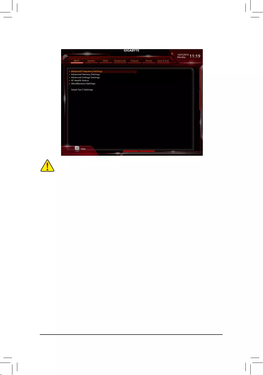
2-2 M.I.T.
Whether the system will work stably with the overclock/overvoltage settings you made is dependent on your overall
systemcongurations.Incorrectlydoingoverclock/overvoltagemayresultindamagetoCPU,chipset,ormemory
and reduce the useful life of these components. This page is for advanced users only and we recommend you not to
alter the default settings to prevent system instability or other unexpected results. (Inadequately altering the settings
may result in system’s failure to boot. If this occurs, clear the CMOS values and reset the board to default values.)
`Advanced Frequency Settings
&CPU Base Clock
Allows you to manually set the CPU base clock in 0.01 MHz increments. (Default: Auto)
Important: It is highly recommended that the CPU frequency be set in accordance with the CPU
specications.
&Host Clock Value
This value changes with the CPU Base Clock setting.
&Graphics Slice Ratio (Note)
AllowsyoutosettheGraphicsSliceRatio.
&Graphics UnSlice Ratio (Note)
AllowsyoutosettheGraphicsUnSliceRatio.
&CPU Upgrade (Note)
Allows you to set the CPU frequency. Options may vary depending on the CPU being used. (Default: Auto)
&CPU Clock Ratio
Allows you to alter the clock ratio for the installed CPU. The adjustable range is dependent on the CPU
being installed.
&CPU Frequency
Displays the current operating CPU frequency.
&FCLK Frequency for Early Power On
Allows you to set the FCLK frequency. Options are: Normal(800Mhz), 1GHz, 400MHz. 1GHz is the default.
(Note) This item is present only when you install a CPU that supports this feature. For more information about
Intel® CPUs’ unique features, please visit Intel’s website.
— 20 —

`Advanced CPU Core Settings
&CPU Clock Ratio, CPU Frequency, FCLK Frequency for Early Power On
The settings above are synchronous to those under the same items on the Advanced Frequency Settings
menu.
&AVX Offset (Note)
AVX offset is the negative offset of AVX ratio.
&Uncore Ratio
Allows you to set the CPU Uncore ratio. The adjustable range is dependent on the CPU being used.
&Uncore Frequency
Displays the current CPU Uncore frequency.
&CPU Flex Ratio Override
EnablesordisablestheCPUFlexRatio.ThemaximumCPUclockratiowillbebasedontheCPU Flex
Ratio Settings value if CPU Clock Ratio is set to Auto. (Default: Disabled)
&CPU Flex Ratio Settings
AllowsyoutosettheCPUFlexRatio.TheadjustablerangemayvarybyCPU.
&Intel(R) Turbo Boost Technology (Note)
Allows you to determine whether to enable the Intel® CPU Turbo Boost technology. Auto lets the BIOS
automaticallycongurethissetting.(Default:Auto)
&Turbo Ratio (Note)
Allows you to set the CPU Turbo ratios for different number of active cores. Auto sets the CPU Turbo ratios
accordingtotheCPUspecications.(Default:Auto)
&Power Limit TDP (Watts) / Power Limit Time
AllowsyoutosetthepowerlimitforCPUTurbomodeandhowlongittakestooperateatthespecied
powerlimit.Ifthespeciedvalueisexceeded,theCPUwillautomaticallyreducethecorefrequencyin
ordertoreducethepower.AutosetsthecurrentlimitaccordingtotheCPUspecications.(Default:Auto)
&Core Current Limit (Amps)
AllowsyoutosetacurrentlimitforCPUTurbomode.WhentheCPUcurrentexceedsthespeciedcurrent
limit, the CPU will automatically reduce the core frequency in order to reduce the current. Auto sets the
powerlimitaccordingtotheCPUspecications.(Default:Auto)
&No. of CPU Cores Enabled (Note)
Allows you to select the number of CPU cores to enable in an Intel® multi-core CPU (the number of CPU
cores may vary by CPU). AutoletstheBIOSautomaticallycongurethissetting.(Default:Auto)
&Hyper-Threading Technology (Note)
Allows you to determine whether to enable multi-threading technology when using an Intel® CPU that
supports this function. This feature only works for operating systems that support multi-processor mode.
AutoletstheBIOSautomaticallycongurethissetting.(Default:Auto)
&Intel(R) Speed Shift Technology (Intel® Speed Shift Technology (Note)
Enables or disables Intel
®
Speed Shift Technology. Enabling this feature allows the processor to ramp up its
operating frequency more quickly and then improves the system responsiveness. (Default: Disabled)
&CPU Enhanced Halt (C1E) (Note)
Enables or disables Intel
®
CPU Enhanced Halt (C1E) function, a CPU power-saving function in system halt
state. When enabled, the CPU core frequency and voltage will be reduced during system halt state to decrease
power consumption. AutoletstheBIOSautomaticallycongurethissetting.(Default:Auto)
(Note) This item is present only when you install a CPU that supports this feature. For more information about
Intel® CPUs’ unique features, please visit Intel’s website.
— 21 —

&C3 State Support (Note 1)
Allows you to determine whether to let the CPU enter C3 mode in system halt state. When enabled, the
CPU core frequency and voltage will be reduced during system halt state to decrease power consumption.
The C3 state is a more enhanced power-saving state than C1. AutoletstheBIOSautomaticallycongure
this setting. (Default: Auto)
&C6/C7 State Support (Note 1)
Allows you to determine whether to let the CPU enter C6/C7 mode in system halt state. When enabled, the
CPU core frequency and voltage will be reduced during system halt state to decrease power consumption.
The C6/C7 state is a more enhanced power-saving state than C3. AutoletstheBIOSautomaticallycongure
this setting. (Default: Auto)
&C8 State Support (Note 1)
Allows you to determine whether to let the CPU enter C8 mode in system halt state. When enabled, the CPU
core frequency and voltage will be reduced during system halt state to decrease power consumption. The
C8 state is a more enhanced power-saving state than C6/C7. AutoletstheBIOSautomaticallycongure
this setting. (Default: Auto)
&Package C State Limit (Note 1)
Allows you to specify the C-state limit for the processor. AutoletstheBIOSautomaticallycongurethis
setting. (Default: Auto)
&CPU Thermal Monitor (Note 1)
Enables or disables Intel® Thermal Monitor function, a CPU overheating protection function. When enabled,
the CPU core frequency and voltage will be reduced when the CPU is overheated. Auto lets the BIOS
automaticallycongurethissetting.(Default:Auto)
&CPU EIST Function (Note 1)
Enables or disables Enhanced Intel® Speed Step Technology (EIST). Depending on CPU loading, Intel®
EIST technology can dynamically and effectively lower the CPU voltage and core frequency to decrease
average power consumption and heat production. AutoletstheBIOSautomaticallycongurethissetting.
(Default: Auto)
&Voltage Optimization
Allows you to determine whether to enable voltage optimization to reduce power consumption. (Default:
Disabled)
&RSR
Allows you to determine whether to automatically lower the CPU turbo ratio if the CPU voltage/temperature
is too high. (Default: Enabled)
&Hardware Prefetcher
Allows you to determine whether to enable hardware prefetcher to prefetch data and instructions from the
memory into the cache. (Default: Enabled)
&Adjacent Cache Line Prefetch
Allows you to determine whether to enable the adjacent cache line prefetch mechanism that lets the
processor retrieve the requested cache line as well as the subsequent cache line. (Default: Enabled)
&ExtremeMemoryProle(X.M.P.)(Note 2)
Allows the BIOS to read the SPD data on XMP memory module(s) to enhance memory performance when
enabled.
Disabled Disables this function. (Default)
Prole1 UsesProle1settings.
Prole2(Note 2) UsesProle2settings.
(Note 1) This item is present only when you install a CPU that supports this feature. For more information about
Intel® CPUs’ unique features, please visit Intel’s website.
(Note 2) This item is present only when you install a CPU and a memory module that support this feature.
— 22 —

&System Memory Multiplier
Allows you to set the system memory multiplier. Auto sets memory multiplier according to memory SPD
data. (Default: Auto)
&Memory Ref Clock
Allows you to manually adjust the memory reference clock. (Default: Auto)
&Memory Odd Ratio(100/133 or 200/266)
Enabled allows Qclk to run in odd frequency. (Default: Auto)
&Memory Frequency (MHz)
Therstmemoryfrequencyvalueisthenormaloperatingfrequencyofthememorybeingused;thesecond
is the memory frequency that is automatically adjusted according to the System Memory Multiplier settings.
`Advanced Memory Settings
&ExtremeMemoryProle(X.M.P.)
(Note)
, System Memory Multiplier, Memory Ref Clock,
Memory Odd Ratio(100/133 or 200/266), Memory Frequency(Mhz)
The settings above are synchronous to those under the same items on the Advanced Frequency Settings
menu.
&Memory Boot Mode (Note)
Provides memory detection and training methods.
Auto LetstheBIOSautomaticallycongurethissetting.(Default)
Normal The BIOS automatically performs memory training. Please note that if the system
becomes unstable or unbootable, try to clear the CMOS values and reset the board
todefaultvalues.(Refertotheintroductionsofthebattery/clearCMOSjumperin
Chapter 1 for how to clear the CMOS values.)
EnableFastBoot Skipmemorydetectionandtraininginsomespeciccriteriaforfastermemory
boot.
Disable Fast Boot Detect and train memory at every single boot.
&Memory Enhancement Settings
Providesseveralmemoryperformanceenhancementsettings:Normal(basicperformance),RelaxOC,
Enhanced Stability, and Enhanced Performance. (Default: Normal)
&Memory Timing Mode
Manual and Advanced Manual allows the Memory Multiplier Tweaker, Channel Interleaving, Rank
Interleaving,andmemorytimingsettingsbelowtobecongurable.Optionsare:Auto(default),Manual,
Advanced Manual.
&ProleDDRVoltage
When using a non-XMP memory module or ExtremeMemoryProle(X.M.P.) is set to Disabled, the value
isdisplayedaccordingtoyourmemoryspecication.WhenExtremeMemoryProle(X.M.P.) is set to
Prole1 or Prole2, the value is displayed according to the SPD data on the XMP memory.
&Memory Multiplier Tweaker
Provides different levels of memory auto-tuning. (Default: Auto)
&Channel Interleaving
Enables or disables memory channel interleaving. Enabled allows the system to simultaneously access
different channels of the memory to increase memory performance and stability. Auto lets the BIOS
automaticallycongurethissetting.(Default:Auto)
&Rank Interleaving
Enables or disables memory rank interleaving. Enabled allows the system to simultaneously access different
ranks of the memory to increase memory performance and stability. Auto lets the BIOS automatically
congurethissetting.(Default:Auto)
(Note) This item is present only when you install a CPU and a memory module that support this feature.
— 23 —

`Channel A/B Memory Sub Timings
This sub-menu provides memory timing settings for each channel of memory. The respective timing setting
screensarecongurableonlywhenMemory Timing Mode is set to Manual or Advanced Manual. Note: Your
system may become unstable or fail to boot after you make changes on the memory timings. If this occurs,
please reset the board to default values by loading optimized defaults or clearing the CMOS values.
`Advanced Voltage Settings
`Advanced Power Settings
&CPU Vcore Loadline Calibration
AllowsyoutocongureLoad-LineCalibrationfortheCPUVcorevoltage.Selectingahigherlevelkeeps
the CPU Vcore voltage more consistent with what is set in BIOS under heavy load. Auto lets the BIOS
automaticallycongurethissettingandsetsthevoltagefollowingIntel’sspecications.(Default:Auto)
&VAXG Loadline Calibration
AllowsyoutocongureLoad-LineCalibrationfortheCPUVAXGvoltage.Selectingahigherlevelkeeps
the CPU VAXG voltage more consistent with what is set in BIOS under heavy load. Auto lets the BIOS
automaticallycongurethissettingandsetsthevoltagefollowingIntel’sspecications.(Default:Auto)
`CPU Core Voltage Control
This section provides CPU voltage control options.
`Chipset Voltage Control
This section provides Chipset voltage control options.
`DRAM Voltage Control
This section provides memory voltage control options.
`PC Health Status
&Reset Case Open Status
Disabled Keeps or clears the record of previous chassis intrusion status. (Default)
Enabled Clears the record of previous chassis intrusion status and the Case Openeldwillshow
«No»atnextboot.
&Case Open
Displays the detection status of the chassis intrusion detection device attached to the motherboard CI
header.Ifthesystemchassiscoverisremoved,thiseldwillshow«Yes»,otherwiseitwillshow«No».To
clear the chassis intrusion status record, set Reset Case Open Status to Enabled, save the settings to
the CMOS, and then restart your system.
&CPU Vcore/CPU VRIN/DRAM Channel A/B Voltage/+3.3V/+5V/+12V/CPU VAXG
Displays the current system voltages.
`Miscellaneous Settings
&Max Link Speed
Allows you to set the operation mode of the PCI Express slots to Gen 1, Gen 2, or Gen 3. Actual operation
modeissubjecttothehardwarespecicationofeachslot.AutoletstheBIOSautomaticallycongurethis
setting. (Default: Auto)
&3DMark01 Enhancement
Allows you to determine whether to enhance some legacy benchmark performance. (Default: Disabled)
— 24 —

`Smart Fan 5 Settings
&Monitor
Allows you to select a target to monitor and to make further adjustment. (Default: CPU FAN)
&Fan Speed Control
Allows you to determine whether to enable the fan speed control function and adjust the fan speed.
Normal Allows the fan to run at different speeds according to the temperature. You can adjust
the fan speed with System Information Viewer based on your system requirements.
(Default)
Silent Allows the fan to run at slow speeds.
Manual Allows you to control the fan speed in the curve graph.
Full Speed Allows the fan to run at full speeds.
&Fan Control Use Temperature Input
Allows you to select the reference temperature for fan speed control.
&Temperature Interval
Allows you to select the temperature interval for fan speed change.
&Fan/Pump Control Mode
Auto Lets the BIOS automatically detect the type of fan/pump installed and sets the optimal
control mode. (Default)
Voltage Voltage mode is recommended for a 3-pin fan/pump.
PWM PWM mode is recommended for a 4-pin fan/pump.
&Temperature
Displays the current temperature of the selected target area.
&Fan Speed
Displays current fan/pump speeds.
&Temperature Warning Control
Sets the warning threshold for temperature. When temperature exceeds the threshold, BIOS will emit
warning sound. Options are: Disabled (default), 60oC/140oF, 70oC/158oF, 80oC/176oF, 90oC/194oF.
&Fan/Pump Fail Warning
Allows the system to emit warning sound if the fan/pump is not connected or fails. Check the fan/pump
condition or fan/pump connection when this occurs. (Default: Disabled)
— 25 —
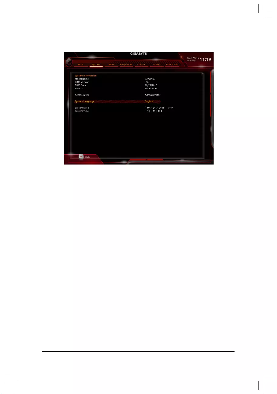
2-3 System
This section provides information on your motherboard model and BIOS version. You can also select the default
language used by the BIOS and manually set the system time.
&Access Level
Displays the current access level depending on the type of password protection used. (If no password is
set, the default will display as Administrator.) The Administrator level allows you to make changes to all
BIOS settings; the User level only allows you to make changes to certain BIOS settings but not all.
&System Language
Selects the default language used by the BIOS.
&System Date
Sets the system date. The date format is week (read-only), month, date, and year. Use <Enter> to switch
betweentheMonth,Date,andYeareldsandusethe<PageUp>or<PageDown>keytosetthedesired
value.
&System Time
Sets the system time. The time format is hour, minute, and second. For example, 1 p.m. is 13:00:00. Use
<Enter>toswitchbetweentheHour,Minute,andSecondeldsandusethe<PageUp>or<PageDown>
key to set the desired value.
— 26 —
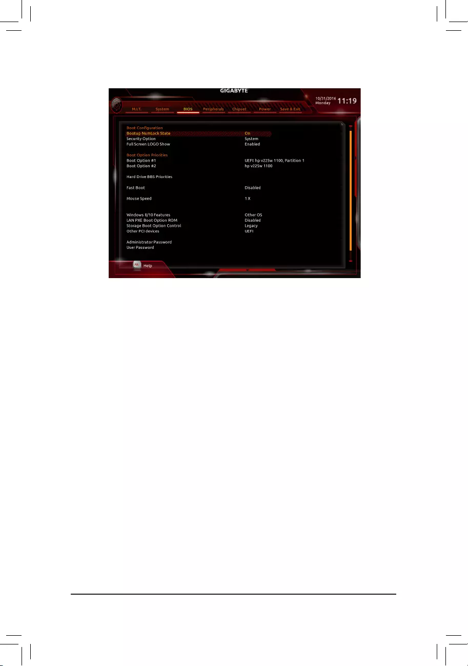
2-4 BIOS
&Bootup NumLock State
Enables or disables Numlock feature on the numeric keypad of the keyboard after the POST. (Default: On)
&Security Option
Specieswhetherapasswordisrequiredeverytimethesystemboots,oronlywhenyouenterBIOSSetup.
Afterconguringthisitem,setthepassword(s)undertheAdministrator Password/User Password item.
Setup A password is only required for entering the BIOS Setup program.
System A password is required for booting the system and for entering the BIOS Setup program.
(Default)
&Full Screen LOGO Show
Allows you to determine whether to display the GIGABYTE Logo at system startup. Disabled skips the
GIGABYTE Logo when the system starts up. (Default: Enabled)
&Boot Option Priorities
Speciestheoverallbootorderfromtheavailabledevices.RemovablestoragedevicesthatsupportGPT
formatwillbeprexedwith«UEFI:»stringonthebootdevicelist.Tobootfromanoperatingsystemthat
supportsGPTpartitioning,selectthedeviceprexedwith»UEFI:»string.
Or if you want to install an operating system that supports GPT partitioning such as Windows 7 64-bit, select
theopticaldrivethatcontainstheWindows764-bitinstallationdiskandisprexedwith»UEFI:»string.
& Hard Drive/CD/DVD ROM Drive/Floppy Drive/Network Device BBS Priorities
Speciesthebootorderforaspecicdevicetype,suchasharddrives,opticaldrives,oppydiskdrives,
and devices that support Boot from LAN function, etc. Press <Enter> on this item to enter the submenu that
presents the devices of the same type that are connected. This item is present only if at least one device
for this type is installed.
&Fast Boot
Enables or disables Fast Boot to shorten the OS boot process. Ultra Fast provides the fastest bootup
speed. (Default: Disabled)
— 27 —

&SATA Support
All Sata Devices All SATA devices are functional in the operating system and during the POST.
(Default)
Last Boot HDD Only Except for the previous boot drive, all SATA devices are disabled before the OS
boot process completes.
ThisitemiscongurableonlywhenFast Boot is set to Enabled or Ultra Fast.
&VGA Support
Allows you to select which type of operating system to boot.
Auto EnableslegacyoptionROMonly.
EFIDriver EnablesEFIoptionROM.(Default)
ThisitemiscongurableonlywhenFast Boot is set to Enabled or Ultra Fast.
&USB Support
Disabled All USB devices are disabled before the OS boot process completes.
Full Initial All USB devices are functional in the operating system and during the POST.
Partial Initial Part of the USB devices are disabled before the OS boot process completes.
(Default)
ThisitemiscongurableonlywhenFast Boot is set to Enabled. This function is disabled when Fast Boot
is set to Ultra Fast.
&PS2 Devices Support
Disabled All PS/2 devices are disabled before the OS boot process completes.
Enabled All PS/2 devices are functional in the operating system and during the POST.
(Default)
ThisitemiscongurableonlywhenFast Boot is set to Enabled. This function is disabled when Fast Boot
is set to Ultra Fast.
&NetWork Stack Driver Support
Disabled Disables booting from the network. (Default)
Enabled Enables booting from the network.
ThisitemiscongurableonlywhenFast Boot is set to Enabled or Ultra Fast.
&Next Boot After AC Power Loss
Normal Boot Enables normal bootup upon the return of the AC power. (Default)
Fast Boot Keeps the Fast Boot settings upon the return of the AC power.
ThisitemiscongurableonlywhenFast Boot is set to Enabled or Ultra Fast.
&Mouse Speed
Allows you to set the mouse cursor movement speed. (Default: 1 X)
&Windows 8/10 Features
Allows you to select the operating system to be installed. (Default: Other OS)
&CSM Support
Enables or disables UEFI CSM (Compatibility Support Module) to support a legacy PC boot process.
Enabled Enables UEFI CSM. (Default)
Disabled Disables UEFI CSM and supports UEFI BIOS boot process only.
ThisitemiscongurableonlywhenWindows 8/10 Features is set to Windows 8/10 or Windows 8/10
WHQL.
&LAN PXE Boot Option ROM
AllowsyoutoselectwhethertoenablethelegacyoptionROMfortheLANcontroller.(Default:Disabled)
ThisitemiscongurableonlywhenCSM Support is set to Enabled.
— 28 —

&Storage Boot Option Control
AllowsyoutoselectwhethertoenabletheUEFIorlegacyoptionROMforthestoragedevicecontroller.
Donotlaunch DisablesoptionROM.
Legacy EnableslegacyoptionROMonly.(Default)
UEFI EnablesUEFIoptionROMonly.
ThisitemiscongurableonlywhenCSM Support is set to Enabled.
&Other PCI devices
AllowsyoutoselectwhethertoenabletheUEFIorLegacyoptionROMforthePCIdevicecontrollerother
than the LAN, storage device, and graphics controllers.
Donotlaunch DisablesoptionROM.
Legacy EnableslegacyoptionROMonly.
UEFI EnablesUEFIoptionROMonly.(Default)
ThisitemiscongurableonlywhenCSM Support is set to Enabled.
&Administrator Password
Allowsyoutocongureanadministratorpassword.Press<Enter>onthisitem,typethepassword,and
thenpress<Enter>.Youwillberequestedtoconrmthepassword.Typethepasswordagainandpress
<Enter>. You must enter the administrator password (or user password) at system startup and when entering
BIOS Setup. Differing from the user password, the administrator password allows you to make changes to
all BIOS settings.
&User Password
Allowsyoutocongureauserpassword.Press<Enter>onthisitem,typethepassword,andthenpress
<Enter>.Youwillberequestedtoconrmthepassword.Typethepasswordagainandpress<Enter>.
You must enter the administrator password (or user password) at system startup and when entering BIOS
Setup. However, the user password only allows you to make changes to certain BIOS settings but not all.
To cancel the password, press <Enter> on the password item and when requested for the password, enter
thecorrectonerst.Whenpromptedforanewpassword,press<Enter>withoutenteringanypassword.
Press<Enter>againwhenpromptedtoconrm.
NOTE:BeforesettingtheUserPassword,besuretosettheAdministratorPasswordrst.
&Secure Boot
AllowsyoutoenableordisableSecureBootandcongurerelatedsettings.
— 29 —
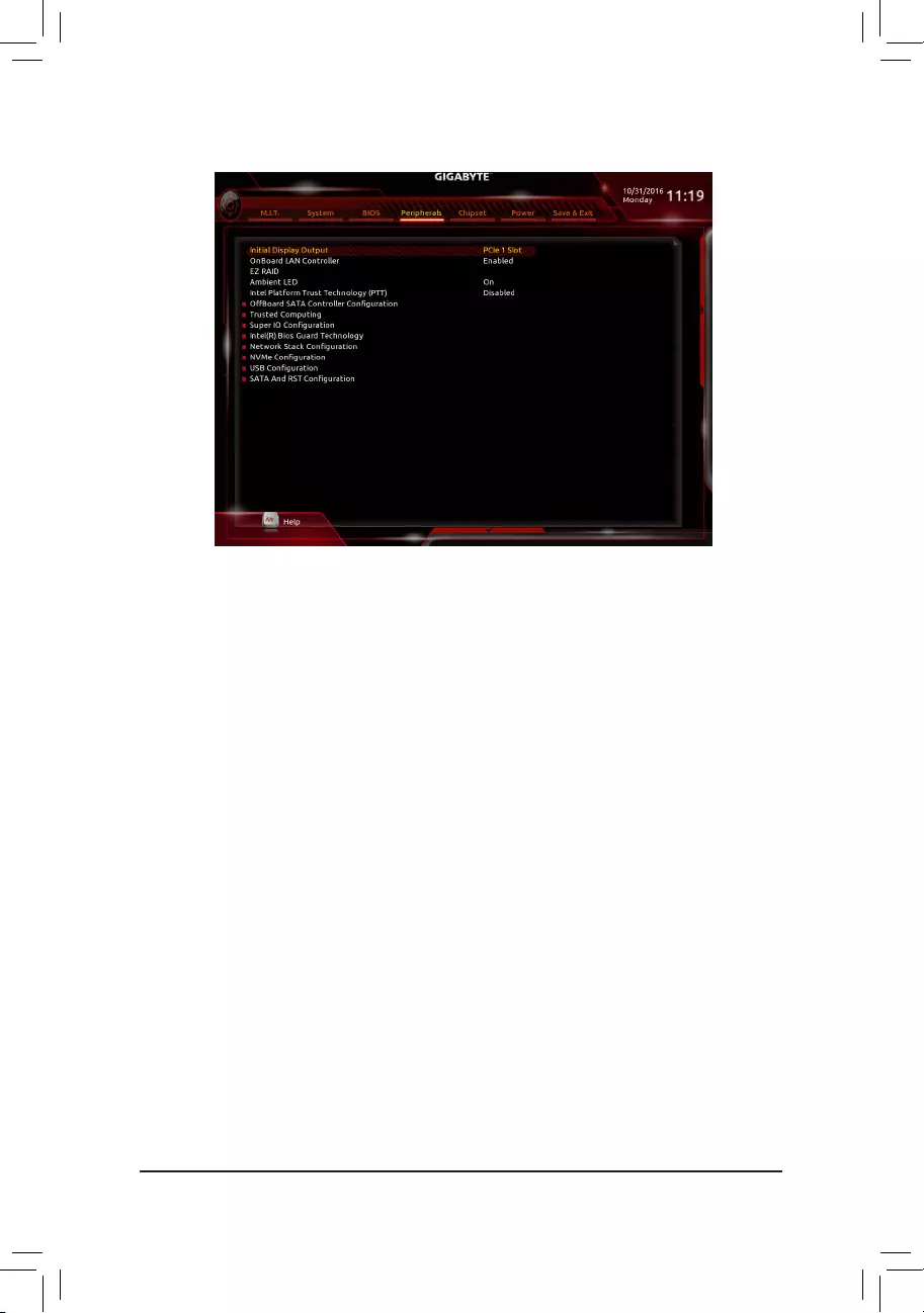
2-5 Peripherals
&Initial Display Output
SpeciestherstinitiationofthemonitordisplayfromtheinstalledPCIExpressgraphicscardortheonboard
graphics.
IGFX Setstheonboardgraphicsastherstdisplay.
PCIe1Slot SetsthegraphicscardonthePCIEX16slotastherstdisplay.(Default)
PCIe2Slot SetsthegraphicscardonthePCIEX4_1slotastherstdisplay.
PCIe3Slot SetsthegraphicscardonthePCIEX4_2slotastherstdisplay.
&OnBoard LAN Controller
Enables or disables the onboard LAN function. (Default: Enabled)
If you wish to install a 3rd party add-in network card instead of using the onboard LAN, set this item to
Disabled.
&EZ RAID
AllowsyoutoquicklysetupaRAIDarray.RefertoChapter3,»ConguringaRAIDSet,»forinstructions
onconguringaRAIDarray.
&Ambient LED
Enables or disables the onboard audio LED function.
Off Disables this function.
On Enables this function. (Default)
&Intel Platform Trust Technology (PTT)
Enables or disables Intel® PTT Technology. (Default: Disabled)
`OffBoardSATAControllerConguration
Displays information on your M.2 PCIe SSD if installed.
`Trusted Computing
Enables or disables Trusted Platform Module (TPM).
— 30 —

`SuperIOConguration
&Serial Port
Enables or disables the onboard serial port. (Default: Enabled)
`Intel(R) Bios Guard Technology
Enables or disables the Intel® BIOS Guard feature, which protects the BIOS from malicious attacks.
`NetworkStackConguration
&Network Stack
Disables or enables booting from the network to install a GPT format OS, such as installing the OS from
the Windows Deployment Services server. (Default: Disabled)
&Ipv4 PXE Support
EnablesordisablesIPv4PXESupport.ThisitemiscongurableonlywhenNetwork Stack is enabled.
&Ipv4 HTTP Support
EnablesordisablesHTTPbootsupportforIPv4.ThisitemiscongurableonlywhenNetwork Stack is
enabled.
&Ipv6 PXE Support
EnablesordisablesIPv6PXESupport.ThisitemiscongurableonlywhenNetwork Stack is enabled.
&Ipv6 HTTP Support
EnablesordisablesHTTPbootsupportforIPv6.ThisitemiscongurableonlywhenNetwork Stack is
enabled.
&PXE boot wait time
Allowsyoutocongurehowlongtowaitbeforeyoucanpress<Esc>toabortthePXEboot.Thisitemis
congurableonlywhenNetwork Stack is enabled. (Default: 0)
&Media detect count
Allowsyoutosetthenumberoftimestocheckthepresenceofmedia.Thisitemiscongurableonlywhen
Network Stack is enabled. (Default: 1)
`NVMeConguration
Displays information on your M.2 NVME PCIe SSD if installed.
`USBConguration
&Legacy USB Support
Allows USB keyboard/mouse to be used in MS-DOS. (Default: Enabled)
&XHCI Hand-off
Determines whether to enable XHCI Hand-off feature for an operating system without XHCI Hand-off
support. (Default: Disabled)
&USB Mass Storage Driver Support
Enables or disables support for USB storage devices. (Default: Enabled)
&Port 60/64 Emulation
Enables or disables emulation of I/O ports 64h and 60h. This should be enabled for full legacy support
for USB keyboards/mice in MS-DOS or in operating system that does not natively support USB devices.
(Default: Enabled)
&Mass Storage Devices
Displays a list of connected USB mass storage devices. This item appears only when a USB storage device
is installed.
— 31 —

`SATAAndRSTConguration
&SATA Controller(s)
Enables or disables the integrated SATA controllers. (Default: Enabled)
&SATA Mode Selection
EnablesordisablesRAIDfortheSATAcontrollersintegratedintheChipsetorcongurestheSATAcontrollers
to AHCI mode.
IntelRSTPremiumWithIntelOptaneSystemAcceleration EnablesRAIDfortheSATAcontroller.
AHCI CongurestheSATAcontrollerstoAHCImode.AdvancedHostControllerInterface
(AHCI)isaninterfacespecicationthatallowsthestoragedrivertoenableadvanced
Serial ATA features such as Native Command Queuing and hot plug. (Default)
&Aggressive LPM Support
Enables or disables the power saving feature, ALPM (Aggressive Link Power Management), for the Chipset
SATA controllers. (Default: Enabled)
&Port 0/1/2/3/4/5
Enables or disables each SATA port. (Default: Enabled)
&Hot plug
Enables or disable the hot plug capability for each SATA port. (Default: Disabled)
&ConguredaseSATA
Enables or disables support for external SATA devices.
— 32 —
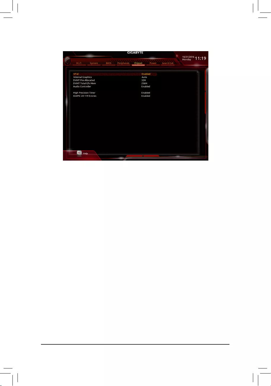
&VT-d (Note)
Enables or disables Intel® Virtualization Technology for Directed I/O. (Default: Enabled)
&Internal Graphics
Enables or disables the onboard graphics function. (Default: Auto)
&DVMT Pre-Allocated
Allows you to set the onboard graphics memory size. Options are: 32M~1024M. (Default: 32M)
&DVMT Total Gfx Mem
Allows you to allocate the DVMT memory size of the onboard graphics. Options are: 128M, 256M, MAX.
(Default: 256M)
&Audio Controller
Enables or disables the onboard audio function. (Default: Enabled)
If you wish to install a 3rd party add-in audio card instead of using the onboard audio, set this item to
Disabled.
&High Precision Timer
Enables or disables High Precision Event Timer (HPET) in the operating system. (Default: Enabled)
&IOAPIC 24-119 Entries
Enables or disables this function. (Default: Enabled)
2-6 Chipset
(Note) This item is present only when you install a CPU that supports this feature. For more information about
Intel® CPUs’ unique features, please visit Intel’s website.
— 33 —
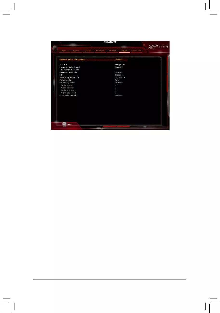
&Platform Power Management
Enables or disables the Active State Power Management function (ASPM). (Default: Disabled)
&PEG ASPM
AllowsyoutoconguretheASPM mode for the device connected to the CPU PEG bus.Thisitemis
congurableonlywhenPlatform Power Management is set to Enabled. (Default: Enabled)
&PCH ASPM
AllowsyoutoconguretheASPMmodeforthedeviceconnectedtoChipset’sPCIExpressbus.Thisitem
iscongurableonlywhenPlatform Power Management is set to Enabled. (Default: Enabled)
&DMI ASPM
AllowsyoutoconguretheASPMmodeforbothCPUsideandChipsetsideoftheDMIlink.Thisitemis
congurableonlywhenPlatform Power Management is set to Enabled. (Default: Enabled)
&AC BACK
Determines the state of the system after the return of power from an AC power loss.
Always Off The system stays off upon the return of the AC power. (Default)
Always On The system is turned on upon the return of the AC power.
Memory The system returns to its last known awake state upon the return of the AC power.
&Power On By Keyboard
Allows the system to be turned on by a PS/2 keyboard wake-up event.
Note: To use this function, you need an ATX power supply providing at least 1A on the +5VSB lead.
Disabled Disables this function. (Default)
Any Key Press any key to turn on the system.
Keyboard98 PressPOWERbuttonontheWindows98keyboardtoturnonthesystem.
Password Set a password with 1~5 characters to turn on the system.
2-7 Power
— 34 —

&Power On Password
Set the password when Power On By Keyboard is set to Password.
Press <Enter> on this item and set a password with up to 5 characters and then press <Enter> to accept.
To turn on the system, enter the password and press <Enter>.
Note: To cancel the password, press <Enter> on this item. When prompted for the password, press <Enter>
again without entering the password to clear the password settings.
&Power On By Mouse
Allows the system to be turned on by a PS/2 mouse wake-up event.
Note: To use this function, you need an ATX power supply providing at least 1A on the +5VSB lead.
Disabled Disables this function. (Default)
Move Move the mouse to turn on the system.
Double Click Double click on left button on the mouse to turn on the system.
&ErP
Determines whether to let the system consume least power in S5 (shutdown) state. (Default: Disabled)
Note: When this item is set to Enabled,thefollowingfunctionswillbecomeunavailable:ResumebyAlarm,
PME event wake up, power on by mouse, power on by keyboard, and wake on LAN.
&Soft-Off by PWR-BTTN
ConguresthewaytoturnoffthecomputerinMS-DOSmodeusingthepowerbutton.
Instant-Off Press the power button and then the system will be turned off instantly. (Default)
Delay 4 Sec. Press and hold the power button for 4 seconds to turn off the system. If the power
button is pressed for less than 4 seconds, the system will enter suspend mode.
&Power Loading
Enables or disables dummy load. When the power supply is at low load, a self-protection will activate causing
it to shutdown or fail. If this occurs, please set to Enabled. AutoletstheBIOSautomaticallycongurethis
setting. (Default: Auto)
&Resume by Alarm
Determines whether to power on the system at a desired time. (Default: Disabled)
If enabled, set the date and time as following:
Wakeupday:Turnonthesystemataspecictimeoneachdayoronaspecicdayinamonth.
Wake up hour/minute/second: Set the time at which the system will be powered on automatically.
Note: When using this function, avoid inadequate shutdown from the operating system or removal of the
AC power, or the settings may not be effective.
&RC6(Render Standby)
Allows you to determine whether to let the onboard graphics enter standby mode to decrease power
consumption. (Default: Enabled)
— 35 —
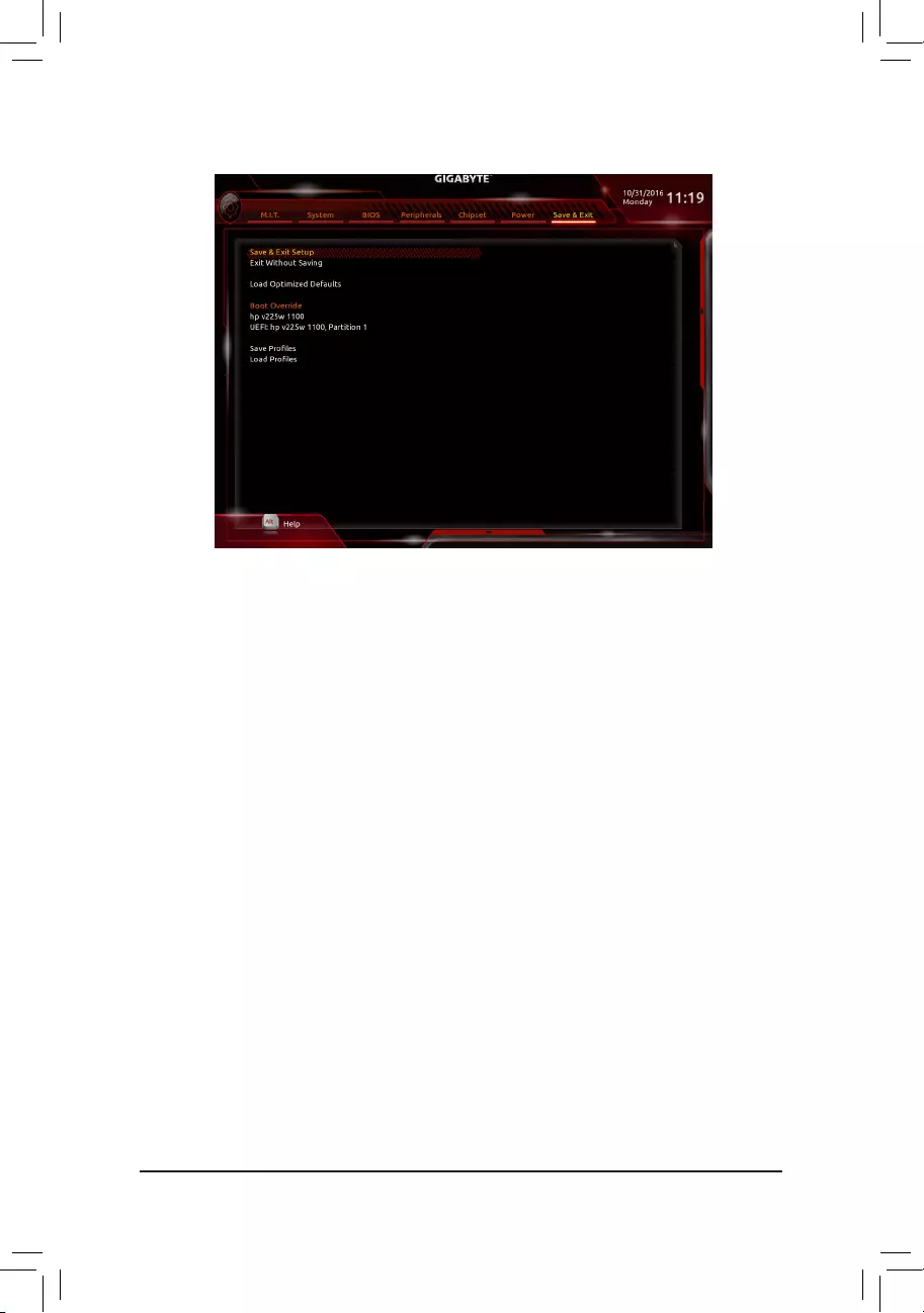
2-8 Save & Exit
&Save & Exit Setup
Press <Enter> on this item and select Yes. This saves the changes to the CMOS and exits the BIOS Setup
program. Select No or press <Esc> to return to the BIOS Setup Main Menu.
&Exit Without Saving
Press <Enter> on this item and select Yes. This exits the BIOS Setup without saving the changes made
in BIOS Setup to the CMOS. Select No or press <Esc> to return to the BIOS Setup Main Menu.
&Load Optimized Defaults
Press <Enter> on this item and select Yes to load the optimal BIOS default settings. The BIOS defaults
settings help the system to operate in optimum state. Always load the Optimized defaults after updating
the BIOS or after clearing the CMOS values.
&Boot Override
Allows you to select a device to boot immediately. Press <Enter> on the device you select and select Yes
toconrm.Yoursystemwillrestartautomaticallyandbootfromthatdevice.
&SaveProles
ThisfunctionallowsyoutosavethecurrentBIOSsettingstoaprole.Youcancreateupto8prolesand
saveasSetupProle1~SetupProle8.Press<Enter>tocomplete.OryoucanselectSelect File in
HDD/FDD/USBtosavetheproletoyourstoragedevice.
&LoadProles
If your system becomes unstable and you have loaded the BIOS default settings, you can use this function
toloadtheBIOSsettingsfromaprole createdbefore,without thehasslesofreconguringtheBIOS
settings.Firstselecttheproleyouwishtoloadandthenpress<Enter>tocomplete.YoucanselectSelect
File in HDD/FDD/USBtoinputtheprolepreviouslycreatedfromyourstoragedeviceorloadtheprole
automatically created by the BIOS, such as reverting the BIOS settings to the last settings that worked
properly (last known good record).
— 36 —

Chapter 3 Appendix
(Note1) AnM.2PCIeSSDcannotbeusedtosetupaRAIDseteitherwithanM.2SATASSDoraSATAhard
drive.
(Note2) Referto»1-7InternalConnectors,»fortheinstallationnoticesfortheM.2andSATAconnectors.
Before you begin, please prepare the following items:
•At least two SATA hard drives or SSDs. (Note 1) (To ensure optimal performance, it is recommended that you
use two hard drives with identical model and capacity). (Note 2)
•Windows setup disk.
•Motherboard driver disk.
•A USB thumb drive.
ConguringtheOnboardSATAController
A. Installing SATA hard drive(s) in your computer
Install the hard drives/SSDs in the Intel® Chipset controlled connectors on the motherboard. Then connect the
power connectors from your power supply to the hard drives.
B.ConguringSATAcontrollermodeinBIOSSetup
MakesuretoconguretheSATAcontrollermodecorrectlyinsystemBIOSSetup.
Steps:
1. Go to PeripheralsSATAAndRSTConguration, make sure SATA Controller(s) is enabled. To create
RAID,setSATA Mode Selection to Intel RST Premium With Intel Optane System Acceleration. Then
save the settings and restart your computer.
2. TousetheEZRAIDfeature,followthestepsin»C-1.»TocongureUEFIRAID,followthestepsin»C-2.»To
enterthelegacyRAIDROM,referto«C-3″formoreinformation.Finally,savethesettingsandexitBIOSSetup.
3-1 ConguringaRAIDSet
RAID Levels
RAID 0 RAID 1 RAID 5 RAID 10
Minimum
Number of Hard
Drives
≥2 2≥3 4
Array Capacity Number of hard
drives * Size of the
smallest drive
Size of the smallest
drive
(Number of hard
drives -1) * Size of
the smallest drive
(Number of hard
drives/2) * Size of the
smallest drive
Fault Tolerance No Yes Yes Yes
The BIOS Setup menus described in this section may differ from the exact settings for your motherboard.
The actual BIOS Setup menu options you will see shall depend on the motherboard you have and
the BIOS version.
C-1. Using EZ RAID
GIGABYTEmotherboardsprovideyouwith theEZRAID feature,allowingyoutoquicklycongureaRAID
arraywithsimpliedsteps.
Steps:
1. After restarting the computer, enter the BIOS Setup and go to Peripherals. Press <Enter> on the EZ RAID
item.SelectthetypeofharddrivesyouuseforRAIDintheType tab and then press <Enter>.
2. Go to the ModetabtoselectaRAIDlevel.RAIDlevelssupportedincludeRAID0,RAID1,RAID10,andRAID
5 (the selections available depend on the number of the hard drives being installed). Then press <Enter> to
move to the Create tab. Click Proceed to begin.
3. Aftercompleting,you’llbebroughtbacktotheIntel(R)RapidStorageTechnologyscreen.UnderRAID Volumes
youcanseethenewRAIDvolume.Toseemoredetailedinformation,press<Enter>onthevolumetocheck
forinformationonRAIDlevel,stripeblocksize,arrayname,andarraycapacity,etc.
— 37 —

PleasevisitGIGABYTE’swebsitefordetailsonconguringaRAIDarray.
C-2.UEFIRAIDConguration
OnlyWindows10/8.164-bitsupportsUEFIRAIDconguration.
Steps:
1. In BIOS Setup, go to BIOS and set Windows 8/10 Features to Windows 8/10 and CSM Support to Disabled.
Save the changes and exit BIOS Setup.
2. After the system reboot, enter BIOS Setup again. Then enter the PeripheralsIntel(R) Rapid Storage
Technology sub-menu.
3. On the Intel(R) Rapid Storage Technology menu, press <Enter> on Create RAID Volume to enter the
Create RAID Volume screen. Enter a volume name with 1~16 letters (letters cannot be special characters)
under the Nameitemandpress<Enter>.Then,selectaRAIDlevel.RAIDlevelssupportedincludeRAID0,
RAID1,Recovery,RAID10,andRAID5(theselectionsavailabledependonthenumberoftheharddrives
being installed). Next, use the down arrow key to move to Select Disks.
4. Under Select Disksitem,selecttheharddrivestobeincludedintheRAIDarray.Pressthe<Space>key
ontheharddrivestobeselected(selectedharddrivesaremarkedwith»X»).Thensetthestripeblocksize.
The stripe block size can be set from 4 KB to 128 KB. Once you have selected the stripe block size, set the
volume capacity.
5. After setting the capacity, move to Create Volume and press <Enter> to begin.
6. After completing, you’ll be brought back to the Intel(R) Rapid Storage Technology screen. Under RAID
VolumesyoucanseethenewRAIDvolume.Toseemoredetailedinformation,press<Enter>onthevolume
tocheckforinformationonRAIDlevel,stripeblocksize,arrayname,andarraycapacity,etc.
C-3.ConguringLegacyRAIDROM
Enter the Intel®legacyRAIDBIOSsetuputilitytocongureaRAIDarray.Skipthisstepandproceedwiththe
installationofWindowsoperatingsystemforanon-RAIDconguration.
Steps:
1. In BIOS Setup, go to BIOS and set CSM Support to Enabled and Storage Boot Option Control to Legacy.
Save the changes and exit BIOS Setup. After the POST memory test begins and before the operating system
bootbegins,lookforamessagewhichsays«Press<Ctrl-I>toenterCongurationUtility».Press<Ctrl>+<I>
toentertheRAIDCongurationUtility.
2. After you press <Ctrl> + <I>, the MAIN MENUscreenwillappear.IfyouwanttocreateaRAIDarray,select
Create RAID Volume in MAIN MENU and press <Enter>.
3. After entering the CREATE VOLUME MENU screen, enter a volume name with 1~16 letters (letters cannot
be special characters) under the Nameitemandpress<Enter>.Then,selectaRAIDlevel.RAIDlevels
supportedincludeRAID0,RAID1,Recovery,RAID10,andRAID5(theselectionsavailabledependonthe
number of the hard drives being installed). Press <Enter> to proceed.
4. Under Diskitem,selecttheharddrivestobeincludedintheRAIDarray.Ifonlytwoharddrivesareinstalled,
they will be automatically assigned to the array. Set the stripe block size if necessary. The stripe block size
can be set from 4 KB to 128 KB. Once you have selected the stripe block size, press <Enter>.
5. Enter the array capacity and press <Enter>. Finally press <Enter> on the Create Volume item to begin
creatingtheRAIDarray.Whenpromptedtoconrmwhethertocreatethisvolume,press<Y>toconrmor
<N> to cancel.
6. Whencompleted,youcanseedetailedinformationabouttheRAIDarrayintheDISK/VOLUME INFORMATION
section,includingtheRAIDlevel,stripeblocksize,arrayname,andarraycapacity,etc.ToexittheRAID
BIOS utility, press <Esc> or select 6. Exit in MAIN MENU.
— 38 —

Installing the SATA RAID/AHCI Driver and Operating System
With the correct BIOS settings, you are ready to install the operating system.
Installing the Operating System
As some operating systems already include Intel®SATARAID/AHCIdriver,youdonotneedtoinstallseparate
RAID/AHCIdriverduringtheWindowsinstallationprocess.Aftertheoperatingsystemisinstalled,werecommend
thatyouinstallallrequireddriversfromthemotherboarddriverdiskusing«XpressInstall»toensuresystem
performance and compatibility. If the operating system to be installed requires that you provide additional SATA
RAID/AHCIdriverduringtheOSinstallationprocess,pleaserefertothestepsbelow:
1. Copy the IRST folder under Boot in the driver disk to your USB thumb drive.
2. Boot from the Windows setup disk and perform standard OS installation steps. When the screen requesting
you to load the driver appears, select Browse.
3. Insert the USB thumb drive and then browse to the location of the driver. The locations of the drivers are
as follows:
Windows32-bit:iRSTf6py-x86
Windows64-bit:iRSTf6py-x64
4. When a screen as shown, select Intel Chipset SATA RAID Controller and click Next to load the driver and
continue the OS installation.
— 39 —
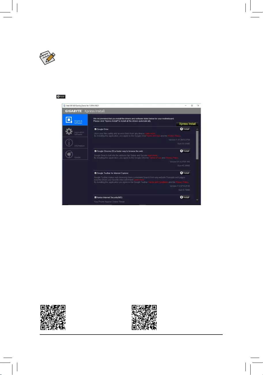
•Beforeinstalling the drivers,rst install theoperating system. (Thefollowing instructions use
Windows 10 as the example operating system.)
•After installing the operating system, insert the motherboard driver disk into your optical drive. Click
onthemessage»Taptochoosewhathappenswiththisdisc»onthetop-rightcornerofthescreen
andselect»RunRun.exe.»(OrgotoMyComputer,double-clicktheopticaldriveandexecutethe
Run.exeprogram.)
3-2 Drivers Installation
«XpressInstall»willautomaticallyscanyoursystemandthenlistallofthedriversthatarerecommendedto
install. You can click the Xpress Installbuttonand«XpressInstall»willinstallalloftheselecteddrivers.Orclick
the arrow icon to individually install the drivers you need.
Please visit GIGABYTE’s website
for more software information.
Please visit GIGABYTE’s website
for details on configuring the audio
software.
— 40 —
Regulatory Statements
Regulatory Notices
This document must not be copied without our written permission, and the contents there of must not be imparted
to a third party nor be used for any unauthorized purpose.
Contravention will be prosecuted. We believe that the information contained herein was accurate in all respects
at the time of printing. GIGABYTE cannot, however, assume any responsibility for errors or omissions in this text.
Also note that the information in this document is subject to change without notice and should not be construed
as a commitment by GIGABYTE.
Our Commitment to Preserving the Environment
Inaddition to high-efciencyperformance, all GIGABYTE motherboardsfulll European Unionregulations
forRoHS(RestrictionofCertainHazardousSubstancesinElectricalandElectronicEquipment)andWEEE
(Waste Electrical and Electronic Equipment) environmental directives, as well as most major worldwide safety
requirements. To prevent releases of harmful substances into the environment and to maximize the use of our
natural resources, GIGABYTE provides the following information on how you can responsibly recycle or reuse
mostofthematerialsinyour»endoflife»product.
Restriction of Hazardous Substances (RoHS) Directive Statement
GIGABYTE products have not intended to add and safe from hazardous substances (Cd, Pb, Hg, Cr+6, PBDE
andPBB).ThepartsandcomponentshavebeencarefullyselectedtomeetRoHSrequirement.Moreover,weat
GIGABYTE are continuing our efforts to develop products that do not use internationally banned toxic chemicals.
Waste Electrical & Electronic Equipment (WEEE) Directive Statement
GIGABYTEwillfulllthenationallawsasinterpretedfromthe2002/96/ECWEEE(WasteElectricalandElectronic
Equipment)directive.TheWEEEDirectivespeciesthetreatment,collection,recyclinganddisposalofelectric
and electronic devices and their components. Under the Directive, used equipment must be marked, collected
separately, and disposed of properly.
WEEE Symbol Statement
The symbol shown below is on the product or on its packaging, which indicates that this product
must not be disposed of with other waste. Instead, the device should be taken to the waste collection
centers for activation of the treatment, collection, recycling and disposal procedure. The separate
collection and recycling of your waste equipment at the time of disposal will help to conserve natural
resources and ensure that it is recycled in a manner that protects human health and the environment.
For more information about where you can drop off your waste equipment for recycling, please contact your
localgovernmentofce,yourhouseholdwastedisposalserviceorwhereyoupurchasedtheproductfordetails
of environmentally safe recycling.
Whenyourelectricalorelectronicequipmentisnolongerusefultoyou,«takeitback»toyourlocalorregional
waste collection administration for recycling.
Ifyouneedfurtherassistanceinrecycling,reusinginyour«endoflife»product,youmaycontactusatthe
Customer Care number listed in your product’s user’s manual and we will be glad to help you with your effort.
Finally, we suggest that you practice other environmentally friendly actions by understanding and using the
energy-saving features of this product (where applicable), recycling the inner and outer packaging (including
shipping containers) this product was delivered in, and by disposing of or recycling used batteries properly.
With your help, we can reduce the amount of natural resources needed to produce electrical and electronic
equipment,minimizetheuseoflandllsforthedisposalof«endoflife»products,andgenerallyimproveour
quality of life by ensuring that potentially hazardous substances are not released into the environment and are
disposed of properly.
— 41 —

FCC Notice (U.S.A. Only)
This equipment has been tested and found to comply with the limits for a Class B digital device, pursuant to Part
15oftheFCCRules.Theselimitsaredesignedtoprovidereasonableprotectionagainstharmfulinterference
in a residential installation. This equipment generates, uses, and can radiate radio frequency energy and, if not
installed and used in accordance with the instructions, may cause harmful interference to radio communications.
However, there is no guarantee that interference will not occur in a particular installation. If this equipment does
cause harmful interference to radio or television reception, which can be determined by turning the equipment
off and on, the user is encouraged to try to correct the interference by one or more of the following measures:
Reorientorrelocatethereceivingantenna.
Increase the separation between the equipment and receiver.
Connect the equipment into an outlet on a circuit different from that to which the receiver is connected.
Consult a dealer or experienced TV/radio technician for help.
Canada, Industry Canada (IC) Notices / Canada, avis d‘Industry Canada (IC)
ThisClassBdigitalapparatuscomplieswithCanadianICES-003andRSS-210.
Operation is subject to the following two conditions: (1) this device may not cause interference, and (2) this
device must accept any interference, including interference that may cause undesired operation of the device.
CetappareilnumériquedeclasseBestconformeauxnormescanadiennesICES-003etRSS-210.
Son fonctionnement est soumis aux deux conditions suivantes : (1) cet appareil ne doit pas causer
d’interférence et (2) cet appareil doit accepter toute interférence, notamment les interférences qui peuvent
affecter son fonctionnement.
— 42 —

— 43 —
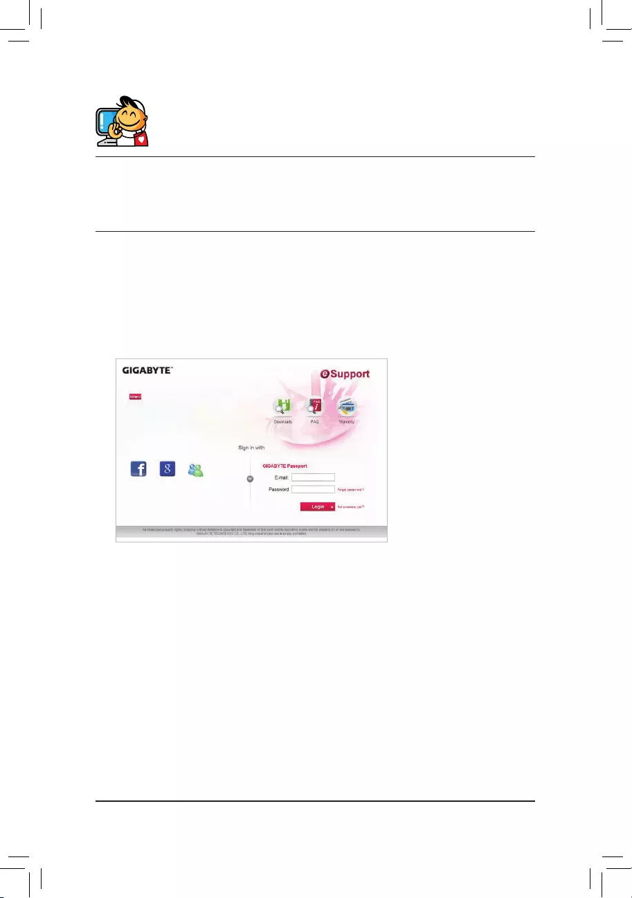
Contact Us
GIGA-BYTE TECHNOLOGY CO., LTD.
Address:No.6,BaoqiangRd.,XindianDist.,NewTaipeiCity231,Taiwan
TEL: +886-2-8912-4000, FAX: +886-2-8912-4005
Tech. and Non-Tech. Support (Sales/Marketing) : http://esupport.gigabyte.com
WEB address (English): http://www.gigabyte.com
WEB address (Chinese): http://www.gigabyte.tw
•GIGABYTE eSupport
To submit a technical or non-technical (Sales/Marketing) question, please link to:
http://esupport.gigabyte.com
— 44 —
Motherboard
GA-Z270P-D3
Dec. 7, 2016
Copyright
© 2016 GIGA-BYTE TECHNOLOGY CO., LTD. All rights reserved.
The trademarks mentioned in this manual are legally registered to their respective owners.
Disclaimer
Information in this manual is protected by copyright laws and is the property of GIGABYTE.
Changes to the specifications and features in this manual may be made by GIGABYTE without prior notice.
No part of this manual may be reproduced, copied, translated, transmitted, or published in any form or
by any means without GIGABYTE’s prior written permission.
„ In order to assist in the use of this product, carefully read the User’s Manual.
„ For product-related information, check on our website at: http://www.gigabyte.com
Identifying Your Motherboard Revision
The revision number on your motherboard looks like this: «REV: X.X.» For example, «REV: 1.0» means
the revision of the motherboard is 1.0. Check your motherboard revision before updating motherboard
BIOS, drivers, or when looking for technical information.
Example:
Motherboard
GA-Z270P-D3
Dec. 7, 2016
-
Драйверы
23
-
Инструкции по эксплуатации
3
Языки:

Gigabyte GA-Z270P-D3 инструкция по эксплуатации
(2 страницы)
- Языки:Английский, Арабский, Болгарский, Венгерский, Вьетнамский, Греческий, Иврит, Индонезийский, Испанский, Итальянский, Китайский, Корейский, Немецкий, Персидский, Польский, Португальский, Румынский, Русский, Сербский, Тайский, Турецкий, Французский, Хорватский, Чешский, Японский
-
Тип:
PDF -
Размер:
8.98 MB -
Описание:
Multilingual Installation Guide


На NoDevice можно скачать инструкцию по эксплуатации для Gigabyte GA-Z270P-D3. Руководство пользователя необходимо для ознакомления с правилами установки и эксплуатации Gigabyte GA-Z270P-D3. Инструкции по использованию помогут правильно настроить Gigabyte GA-Z270P-D3, исправить ошибки и выявить неполадки.