
- Manuals
- Brands
- Gigabyte Manuals
- Motherboard
- GA-Z97X-SLI
- User manual
-
Contents
-
Table of Contents
-
Bookmarks
Quick Links
GA-Z97X-SLI
User’s Manual
Rev. 1101
12ME-Z97XSLI-1101R
Related Manuals for Gigabyte GA-Z97X-SLI
Summary of Contents for Gigabyte GA-Z97X-SLI
-
Page 1
GA-Z97X-SLI User’s Manual Rev. 1101 12ME-Z97XSLI-1101R… -
Page 3: Identifying Motherboard Revision
No part of this manual may be reproduced, copied, translated, transmitted, or published in any form or by any means without GIGABYTE’s prior written permission. Documentation Classifications In order to assist in the use of this product, GIGABYTE provides the following types of documentations: „ For detailed product information, carefully read the User’s Manual.
-
Page 4: Table Of Contents
Table of Contents Box Contents ……………………6 Optional Items …………………….6 GA-Z97X-SLI Motherboard Layout ………………7 GA-Z97X-SLI Motherboard Block Diagram …………..8 Chapter 1 Hardware Installation ………………9 Installation Precautions ………………9 1-2 Product Specifications ………………10 Installing the CPU and CPU Cooler …………… 13 1-3-1 Installing the CPU ………………..13…
-
Page 5
Chapter 3 Configuring SATA Hard Drive(s) …………..60 3-1 Configuring SATA Controllers …………….. 60 Installing the SATA RAID/AHCI Driver and Operating System ……. 72 Chapter 4 Appendix ………………….76 Drivers Installation ………………… 76 Regulatory Statements ………………..77 Contact Us …………………… 79 — 5 -… -
Page 6: Box Contents
Box Contents ; GA-Z97X-SLI motherboard ; Motherboard driver disk ; User’s Manual ; Two SATA cables ; I/O Shield ; One 2-Way SLI bridge connector The box contents above are for reference only and the actual items shall depend on the product package you obtain.
-
Page 7: Ga-Z97X-Sli Motherboard Layout
GA-Z97X-SLI Motherboard Layout CPU_FAN KB_MS_USB ATX_12V_2X4 CPU_OPT LGA1150 HDMI R_USB30 USB30_LAN SYS_FAN1 AUDIO PCIEX1_1 GA-Z97X-SLI Intel ® GbE LAN PCIEX16 PCIEX1_2 ® Intel ® Super I/O PCIEX1_3 PCIEX8 CODEC PCI1 PCIe to PCI Bridge PCI2 B_BIOS M_BIOS CLR_CMOS F_USB1 F_AUDIO…
-
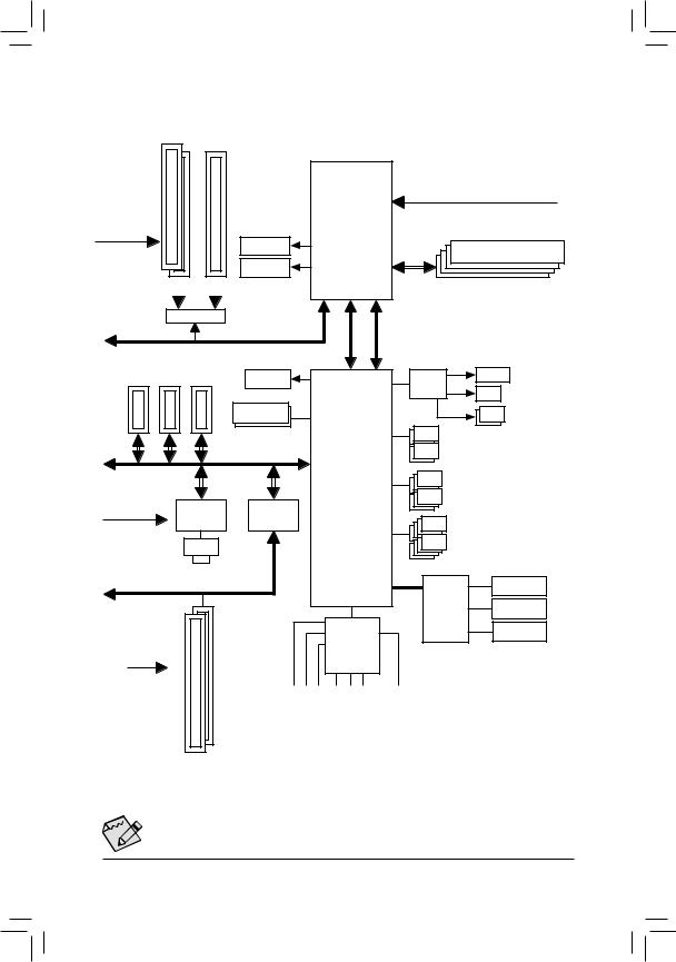
Page 8: Ga-Z97X-Sli Motherboard Block Diagram
GA-Z97X-SLI Motherboard Block Diagram 2 PCI Express x8 1 PCI Express x16 CPU CLK+/- (100 MHz) LGA1150 PCIe CLK (100 MHz) DDR3 1600/1333 MHz HDMI Dual Channel Memory DVI-D Switch PCI Express Bus 3 PCI Express x1 D-Sub Switch SATA Express Dual BIOS 2 SATA 6Gb/s…
-
Page 9: Chapter 1 Hardware Installation
Chapter 1 Hardware Installation Installation Precautions The motherboard contains numerous delicate electronic circuits and components which can become damaged as a result of electrostatic discharge (ESD). Prior to installation, carefully read the user’s manual and follow these procedures: • Prior to installation, make sure the chassis is suitable for the motherboard. • Prior to installation, do not remove or break motherboard S/N (Serial Number) sticker or warranty sticker provided by your dealer.
-
Page 10: Product Specifications
* D ue to a Windows 32-bit operating system limitation, when more than 4 GB of physical memory is installed, the actual memory size displayed will be less than the size of the physical memory installed. Dual channel memory architecture Š Support for DDR3 1600/1333 MHz memory modules Š Support for non-ECC memory modules Š Support for Extreme Memory Profile (XMP) memory modules Š ( Go to GIGABYTE’s website for the latest supported memory speeds and memory modules.) Onboard Integrated Graphics Processor: Š 1 x D-Sub port, supporting a maximum resolution of 1920×1200@60Hz Graphics 1 x DVI-D port, supporting a maximum resolution of 1920×1200@60Hz * The DVI-D port does not support D-Sub connection by adapter. 1 x HDMI port, supporting a maximum resolution of 4096×2160@24Hz or 2560×1600@60Hz * S upport for HDMI 1.4a version.
-
Page 11
Storage Interface Š Chipset: 1 x M.2 PCIe connector 1 x SATA Express connector 6 x SATA 6Gb/s connectors ( M.2, SATA Express, and SATA3 4/5 connectors can only be used one at a time. The SATA3 4/5 connectors will become unavailable when an M.2 SSD is installed.) Support for RAID 0, RAID 1, RAID 5, and RAID 10 Chipset: Š 6 x USB 3.0/2.0 ports (4 ports on the back panel, 2 ports available through the internal USB header) 8 x USB 2.0/1.1 ports (2 ports on the back panel, 6 ports available through the internal USB headers) Internal 1 x 24-pin ATX main power connector… -
Page 12
Š System ATX Form Factor; 30.5cm x 21.4cm Form Factor Š * G IGABYTE reserves the right to make any changes to the product specifications and product-related information without prior notice. * P lease visit the Support & DownloadsUtility page on GIGABYTE’s website to check the supported operating system(s) for the software listed in the «Unique Features» and «Bundled Software» columns. Hardware Installation — 12 -… -
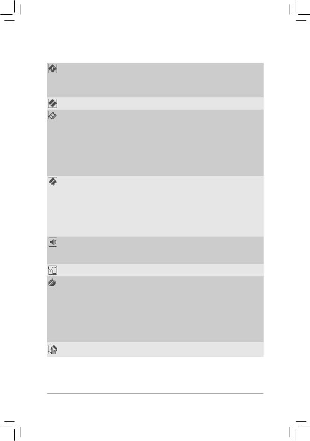
Page 13: Installing The Cpu And Cpu Cooler
Read the following guidelines before you begin to install the CPU: • Make sure that the motherboard supports the CPU. (Go to GIGABYTE’s website for the latest CPU support list.) • Always turn off the computer and unplug the power cord from the power outlet before installing the CPU to prevent hardware damage.
-
Page 14
B. Follow the steps below to correctly install the CPU into the motherboard CPU socket. • Before installing the CPU, make sure to turn off the computer and unplug the power cord from the power outlet to prevent damage to the CPU. •… -
Page 15: Installing The Cpu Cooler
1-3-2 Installing the CPU Cooler Follow the steps below to correctly install the CPU cooler on the motherboard. (The following procedure uses Intel boxed cooler as the example cooler.) ® Male Push Pin Direction of the Arrow Sign The Top on the Male of Female Push Pin Push Pin Female Push Pin Step 1: Step 2: Apply an even and thin layer of thermal grease on Before installing the cooler, note the direction of the the surface of the installed CPU.
-
Page 16: Installing The Memory
• Make sure that the motherboard supports the memory. It is recommended that memory of the same capacity, brand, speed, and chips be used. (Go to GIGABYTE’s website for the latest supported memory speeds and memory modules.) • Always turn off the computer and unplug the power cord from the power outlet before installing the memory to prevent hardware damage.
-
Page 17: Installing A Memory
1-4-2 Installing a Memory Before installing a memory module, make sure to turn off the computer and unplug the power cord from the power outlet to prevent damage to the memory module. DDR3 and DDR2 DIMMs are not compatible to each other or DDR DIMMs. Be sure to install DDR3 DIMMs on this motherboard.
-
Page 18: Installing An Expansion Card
Installing an Expansion Card Read the following guidelines before you begin to install an expansion card: • Make sure the motherboard supports the expansion card. Carefully read the manual that came with your expansion card. • Always turn off the computer and unplug the power cord from the power outlet before installing an expansion card to prevent hardware damage.
-
Page 19: Setting Up Amd Crossfire ™ /Nvidia ® Sli ™ Configuration
Setting up AMD CrossFire /NVIDIA Configuration ™ ® ™ A. System Requirements — Windows 8.1/8/7 operating system — A CrossFire/SLI-supported motherboard with two PCI Express x16 slots and correct driver — Two CrossFire/SLI-ready graphics cards of identical brand and chip and correct driver — CrossFire /SLI bridge connector (Note)
-
Page 20: Back Panel Connectors
Back Panel Connectors USB 2.0/1.1 Port The USB port supports the USB 2.0/1.1 specification. Use this port for USB devices such as a USB keyboard/mouse, USB printer, USB flash drive and etc. PS/2 Keyboard/Mouse Port Use this port to connect a PS/2 mouse or keyboard. D-Sub Port The D-Sub port supports a 15-pin D-Sub connector and supports a maximum resolution of 1920×1200@60Hz (the actual resolutions supported depend on the monitor being used). Connect a monitor that supports D-Sub connection to this port.
-
Page 21
USB 3.0/2.0 Port The USB 3.0 port supports the USB 3.0 specification and is compatible to the USB 2.0/1.1 specification. Use this port for USB devices such as a USB keyboard/mouse, USB printer, USB flash drive and etc. RJ-45 LAN Port The Gigabit Ethernet LAN port provides Internet connection at up to 1 Gbps data rate. The following describes the states of the LAN port LEDs. Connection/ Connection/Speed LED: Activity LED: Speed LED Activity LED State Description… -
Page 22: Internal Connectors
Internal Connectors 14 15 ATX_12V_2X4 F_AUDIO SPDIF_O CPU_FAN F_USB30 SYS_FAN1/2/3 F_USB1/F_USB2/F_USB3 CPU_OPT COMA SATA_EXPRESS SATA3 0/1/2/3/4/5 CLR_CMOS F_PANEL Read the following guidelines before connecting external devices: • First make sure your devices are compliant with the connectors you wish to connect. •…
-
Page 23
1/2) ATX_12V_2X4/ATX (2×4 12V Power Connector and 2×12 Main Power Connector) With the use of the power connector, the power supply can supply enough stable power to all the components on the motherboard. Before connecting the power connector, first make sure the power supply is turned off and all devices are properly installed. The power connector possesses a foolproof design. Connect the power supply cable to the power connector in the correct orientation. -
Page 24: Water Cooling Cpu Fan Header
3/4) CPU_FAN/SYS_FAN1/SYS_FAN2/SYS_FAN3 (Fan Headers) All fan headers on this motherboard are 4-pin. Most fan headers possess a foolproof insertion design. When connecting a fan cable, be sure to connect it in the correct orientation (the black connector wire is the ground wire). The motherboard supports CPU fan speed control, which requires the use of a CPU fan with fan speed control design. For optimum heat dissipation, it is recommended that a system fan be installed inside the chassis.
-
Page 25
6) SATA_EXPRESS (SATA Express Connector) The SATA Express connector supports a single SATA Express device. B S S 7) SATA3 0/1/2/3/4/5 (SATA 6Gb/s Connectors) The SATA connectors conform to SATA 6Gb/s standard and are compatible with SATA 3Gb/s and SATA 1.5Gb/s standard. -
Page 26
B S_ M.2 (M.2 Connector) You can insert an M.2 SSD into this connector. S B_ Follow the steps below to correctly install an M.2 SSD in the M.2 connector. F_USB3 F Step 1: Step 2: Use a screw driver to unfasten the screw and nut Slide the M.2 SSD into the connector at an from the motherboard.
 -
Page 27: Front Panel Header
9) F_PANEL (Front Panel Header) Connect the power switch, reset switch, speaker, chassis intrusion switch/sensor and system status indicator on the chassis to this header according to the pin assignments below. Note the positive and negative pins before connecting the cables. Power LED Power Switch Speaker…
-
Page 28
10) F_AUDIO (Front Panel Audio Header) The front panel audio header supports Intel High Definition audio (HD) and AC’97 audio. You may connect your chassis front panel audio module to this header. Make sure the wire assignments of the module connector match the pin assignments of the motherboard header. Incorrect connection between the module connector and the motherboard header will make the device unable to work or even damage it. For HD Front Panel Audio: For AC’97 Front Panel Audio: Pin No. -
Page 29
12) F_USB30 (USB 3.0/2.0 Header) The header conforms to USB 3.0/2.0 specification and can provide two USB ports. For purchasing the optional 3.5″ front panel that provides two USB 3.0/2.0 ports, please contact the local dealer. Pin No. Definition Pin No. Definition VBUS SSRX1- SSRX1+ SSTX2+ SSTX1- SSTX2- SSTX1+ SSRX2+ SSRX2- VBUS No Pin 13) F_USB1/F_USB2/F_USB3 (USB 2.0/1.1 Headers) The headers conform to USB 2.0/1.1 specification. Each USB header can provide two USB ports via an optional USB bracket. -
Page 30
14) COMA (Serial Port Header) The COM header can provide one serial port via an optional COM port cable. For purchasing the optional COM port cable, please contact the local dealer. Pin No. Definition NDCD- NSIN NSOUT NDTR- DEBUG PORT NDSR- NRTS- NCTS-… -
Page 31: Battery
16) BAT (Battery) The battery provides power to keep the values (such as BIOS configurations, date, and time information) in the CMOS when the computer is turned off. Replace the battery when the battery voltage drops to a low level, or the CMOS values may not be accurate or may be lost. You may clear the CMOS values by removing the battery: 1.
-
Page 32: Chapter 2 Bios Setup
To access the BIOS Setup program, press the <Delete> key during the POST when the power is turned on. To upgrade the BIOS, use either the GIGABYTE Q-Flash or @BIOS utility. Q-Flash allows the user to quickly and easily upgrade or back up BIOS without entering the operating system.
-
Page 33: Startup Screen
Startup Screen The following startup Logo screen will appear when the computer boots. Function Keys Function Keys: <DEL>: BIOS SETUPQ-FLASH Press the <Delete> key to enter BIOS Setup or to access the Q-Flash utility in BIOS Setup. <F9>: SYSTEM INFORMATION Press the <F9>…
-
Page 34: The Main Menu
The Main Menu A. Startup Guide (Default) The Startup Guide screen simplifies conventional complicated BIOS setup menus and presents only the most frequently used options in the easy-to-use interface. It helps first-time users to perform basic system setups more quickly and easily. B. ST Mode (Smart Tweak Mode) Differing from traditional UEFI interface, the ST Mode provides a fancy and user-friendly BIOS environment where users can easily point and click through various settings and make adjustments for optimum performance. In ST Mode, you can use your mouse to move through the option menus for quick configuration or press <F2>…
-
Page 35
C. Classic Setup Classic Setup is the conventional BIOS Setup interface where you can press the arrow keys on your keyboard to move among the items and press <Enter> to accept or enter a sub-menu. Or you can use your mouse to select the item you want. -
Page 36: System Information
BIOS Setup Menus „ M.I.T. Use this menu to configure the clock, frequency, and voltages of your CPU and memory, etc. Or check the system/CPU temperatures, voltages, and fan speeds. „ System Information Use this menu to configure the default language used by the BIOS and system time and date. „ BIOS Features Use this menu to configure the device boot order and advanced features available on the CPU. „ Peripherals Use this menu to configure all peripheral devices, such as SATA, USB, integrated audio, and integrated LAN, etc. „ Power Management Use this menu to configure all the power-saving functions. „ Save & Exit Save all the changes made in the BIOS Setup program to the CMOS and exit BIOS Setup. You can save the current BIOS settings to a profile or load optimized defaults for optimal-performance system operations.
-
Page 37: M.i.t
M.I.T. Whether the system will work stably with the overclock/overvoltage settings you made is dependent on your overall system configurations. Incorrectly doing overclock/overvoltage may result in damage to CPU, chipset, or memory and reduce the useful life of these components. This page is for advanced users only and we recommend you not to alter the default settings to prevent system instability or other unexpected results. (Inadequately altering the settings may result in system’s failure to boot. If this occurs, clear the CMOS values and reset the board to default values.) This section provides information on the BIOS version, CPU base clock, CPU frequency, memory frequency,…
-
Page 38
` M.I.T. Current Status This screen provides information on CPU/memory frequencies/parameters. ` Advanced Frequency Settings & Performance Upgrade (Note) Provides you with five different overclocking configurations. Options are: 20% Upgrade, 40% Upgrade, 60% Upgrade, 80% Upgrade, 100% Upgrade. (Default: Auto) & CPU Base Clock Allows you to manually set the CPU base clock in 0.01 MHz increments. (Default: Auto) Important: It is highly recommended that the CPU frequency be set in accordance with the CPU specifications. -
Page 39
& CPU Upgrade (Note) Allows you to set the CPU frequency. Options may vary depending on the CPU being used. (Default: Auto) & CPU Clock Ratio Allows you to alter the clock ratio for the installed CPU. The adjustable range is dependent on the CPU being installed. & CPU Frequency Displays the current operating CPU frequency. ` Advanced CPU Core Settings &… -
Page 40
& Turbo Ratio (1-Core Active~4-Core Active) (Note) Allows you to set the CPU Turbo ratios for different number of active cores. Auto sets the CPU Turbo ratios according to the CPU specifications. (Default: Auto) & Turbo Power Limit (Watts) Allows you to set a power limit for CPU Turbo mode. When the CPU power consumption exceeds the specified power limit, the CPU will automatically reduce the core frequency in order to reduce the power. -
Page 41: Advanced Memory Settings
& Extreme Memory Profile (X.M.P.) (Note) Allows the BIOS to read the SPD data on XMP memory module(s) to enhance memory performance when enabled. Disabled Disables this function. (Default) Uses Profile 1 settings. Profile1 Uses Profile 2 settings. (Note) Profile2 & System Memory Multiplier Allows you to set the system memory multiplier. Auto sets memory multiplier according to memory SPD data. (Default: Auto) & Memory Frequency (MHz) The first memory frequency value is the normal operating frequency of the memory being used; the second is the memory frequency that is automatically adjusted according to the System Memory Multiplier settings. ` Advanced Memory Settings &…
-
Page 42: Channel Interleaving
& Memory Enhancement Settings Provides three different memory performance enhancement settings: Normal (basic performance), Enhanced Stability, and Enhanced Performance. (Default: Normal) & Memory Timing Mode Manual and Advanced Manual allows the Channel Interleaving, Rank Interleaving, and memory timing settings below to be configurable. Options are: Auto (default), Manual, Advanced Manual. & Profile DDR Voltage When using a non-XMP memory module or Extreme Memory Profile (X.M.P.) is set to Disabled, the value is displayed according to your memory specification. When Extreme Memory Profile (X.M.P.) is set to Profile1 or Profile2, the value is displayed according to the SPD data on the XMP memory.
-
Page 43
` Advanced Voltage Settings This sub-menu allows you to set CPU, chipset and memory voltages. — 43 — BIOS Setup… -
Page 44: Pc Health Status
` PC Health Status & Reset Case Open Status Disabled Keeps or clears the record of previous chassis intrusion status. (Default) Clears the record of previous chassis intrusion status and the Case Open field will show Enabled «Close» at next boot. & Case Open Displays the detection status of the chassis intrusion detection device attached to the motherboard CI header. If the system chassis cover is removed, this field will show «Yes», otherwise it will show «No». To clear the chassis intrusion status record, set Reset Case Open Status to Enabled, save the settings to the CMOS, and then restart your system.
-
Page 45
& CPU Vcore/CPU VRIN/DRAM Voltage/+3.3V/+5V/+12V/CPU VAXG Displays the current system voltages. & CPU/System Temperature Displays current CPU/System temperature. & CPU/CPU OPT/System Fan Speed Displays current CPU/CPU_OPT/system fan speeds. & CPU/System Temperature Warning Sets the warning threshold for CPU/system temperature. When temperature exceeds the threshold, BIOS will emit warning sound. Options are: Disabled (default), 60 C/140 F, 70… -
Page 46
& 2nd System Fan Speed Control (SYS_FAN2 Connector) Allows you to determine whether to enable the fan speed control function and adjust the fan speed. Allows the fan to run at different speeds according to the system temperature. You Normal can adjust the fan speed with System Information Viewer based on your system requirements. (Default) Allows the fan to run at slow speeds. -
Page 47: Miscellaneous Settings
` Miscellaneous Settings & PCIe Slot Configuration Allows you to set the operation mode of the PCI Express slots to Gen 1, Gen 2, or Gen 3. Actual operation mode is subject to the hardware specification of each slot. Auto lets the BIOS automatically configure this setting. (Default: Auto) & DMI Gen2 Speed Allows you to configure the DMI link speed. Auto Lets the BIOS automatically configure this setting. Enabled Sets the DMI link speed to Gen 2. (Default) Sets the DMI link speed to Gen 1. Disabled &…
-
Page 48: System Information
System Information This section provides information on motherboard model and BIOS version. You can also select the default language used by the BIOS and manually set the system time. & System Language Selects the default language used by the BIOS. &…
-
Page 49: Bios Features
BIOS Features & Boot Option Priorities Specifies the overall boot order from the available devices. Removable storage devices that support GPT format will be prefixed with «UEFI:» string on the boot device list. To boot from an operating system that supports GPT partitioning, select the device prefixed with «UEFI:» string. Or if you want to install an operating system that supports GPT partitioning such as Windows 7 64-bit, select the optical drive that contains the Windows 7 64-bit installation disk and is prefixed with «UEFI:» string. & Bootup NumLock State Enables or disables Numlock feature on the numeric keypad of the keyboard after the POST. (Default: Enabled) — 49 — BIOS Setup…
-
Page 50: Security Option
System (Default) & Full Screen LOGO Show Allows you to determine whether to display the GIGABYTE Logo at system startup. Disabled skips the GIGABYTE Logo when the system starts up. (Default: Enabled) & Fast Boot Enables or disables Fast Boot to shorten the OS boot process. Ultra Fast provides the fastest bootup speed. (Default: Disabled)
-
Page 51: Boot Mode Selection
& Execute Disable Bit (Note) Enables or disables Intel Execute Disable Bit function. This function may enhance protection for the ® computer, reducing exposure to viruses and malicious buffer overflow attacks when working with its supporting software and system. (Default: Enabled) & Intel Virtualization Technology (Note) Enables or disables Intel Virtualization Technology. Virtualization enhanced by Intel…
-
Page 52: Network Stack
& Other PCI Device ROM Priority Allows you to select whether to enable the UEFI or Legacy option ROM for the PCI device controller other than the LAN, storage device, and graphics controllers. Legacy OpROM Enables legacy option ROM only. UEFI OpROM Enables UEFI option ROM only. (Default) This item is configurable only when CSM Support is set to Always.
-
Page 53: Peripherals
Peripherals & Initial Display Output Specifies the first initiation of the monitor display from the installed PCI graphics card, PCI Express graphics card or the onboard graphics. IGFX Sets the onboard graphics as the first display. Sets the graphics card on the PCIEX16 slot as the first display. (Default) PCIe 1 Slot Sets the graphics card on the PCIEX8 slot as the first display. PCIe 2 Slot PCI Sets the graphics card on the PCI slot as the first display. & PCH LAN Controller Enables or disables the onboard LAN function. (Default: Enabled) If you wish to install a 3rd party add-in network card instead of using the onboard LAN, set this item to Disabled.
-
Page 54: Audio Controller
The USB 3.0 ports are routed to the EHCI controller and the xHCI controller is turned Disabled off. All USB 3.0 devices function as High Speed devices regardless of xHCI software support/availability. & Audio Controller Enables or disables the onboard audio function. (Default: Enabled) If you wish to install a 3rd party add-in audio card instead of using the onboard audio, set this item to Disabled.
-
Page 55: Hot Plug
` SATA Configuration & Integrated SATA Controller Enables or disables the integrated SATA controllers. (Default: Enabled) & SATA Mode Selection Enables or disables RAID for the SATA controllers integrated in the Chipset or configures the SATA controllers to AHCI mode. IDE Configures the SATA controller to IDE mode. Enables RAID for the SATA controller. RAID AHCI C onfigures the SATA controllers to AHCI mode. Advanced Host Controller Interface (AHCI) is an interface specification that allows the storage driver to enable advanced Serial ATA features such as Native Command Queuing and hot plug. (Default) & M.2 PCIE SSD RAID Mode Enables or disables Intel Rapid Storage Technology for the M.2 PCIe SSD. (Default: Enabled) ®…
-
Page 56: Parallel Port
` Super IO Configuration This section provides information on the super I/O chip and allows you to configure the serial port and parallel port. & Serial Port A Enables or disables the onboard serial port. (Default: Enabled) & Parallel Port Enables or disables the onboard parallel port. (Default: Enabled) & Device Mode T his item is configurable only when Parallel Port is set to Enabled. Selects an operating mode for the onboard parallel (LPT) port. Options are: Standard Parallel Port Mode (Default), EPP Mode (Enhanced Parallel Port), ECP Mode (Extended Capabilities Port), EPP Mode & ECP Mode. ` Intel(R) Smart Connect Technology & ISCT Support Enables or disables Intel Smart Connect Technology. (Default: Disabled) ®…
-
Page 57: Power Management
Power Management & Power Loading Enables or disables dummy load. When the power supply is at low load, a self-protection will activate causing it to shutdown or fail. If this occurs, please set to Enabled. Auto lets the BIOS automatically configure this setting. (Default: Auto) & Resume by Alarm Determines whether to power on the system at a desired time. (Default: Disabled) If enabled, set the date and time as following: Wake up day: Turn on the system at a specific time on each day or on a specific day in a month.
-
Page 58: Power On Password
& Power On By Keyboard Allows the system to be turned on by a PS/2 keyboard wake-up event. Note: To use this function, you need an ATX power supply providing at least 1A on the +5VSB lead. Disabled Disables this function. (Default) Set a password with 1~5 characters to turn on the system. Password Keyboard 98 Press POWER button on the Windows 98 keyboard to turn on the system.
-
Page 59: Save & Exit
Save & Exit & Save & Exit Setup Press <Enter> on this item and select Yes. This saves the changes to the CMOS and exits the BIOS Setup program. Select No or press <Esc> to return to the BIOS Setup Main Menu. &…
-
Page 60: Chapter 3 Configuring Sata Hard Drive(S)
Chapter 3 Configuring SATA Hard Drive(s) RAID Levels RAID 0 RAID 1 RAID 5 RAID 10 Minimum Number of Hard ≥2 ≥3 ≥4 Drives Array Capacity Number of hard Size of the smallest (Number of hard (Number of hard drives * Size of the drive drives -1) * Size of drives/2) * Size of the smallest drive the smallest drive smallest drive Fault Tolerance To configure SATA hard drive(s), follow the steps below: A.
-
Page 61
B. Configuring SATA controller mode in BIOS Setup Make sure to configure the SATA controller mode correctly in system BIOS Setup. Step 1: Turn on your computer and press <Delete> to enter BIOS Setup during the POST (Power-On Self-Test). Go to PeripheralsSATA Configuration, make sure Integrated SATA Controller is enabled. To create RAID, set SATA Mode Selection to RAID (Figure 1). If you do not want to create RAID, set this item to IDE or AHCI. Figure 1 Step 2: If you want to configure UEFI RAID, follow the steps in «C-1.» To enter the legacy RAID ROM, save the settings and exit BIOS Setup. Refer to «C-2» for more information. The BIOS Setup menus described in this section may differ from the exact settings for your motherboard. -
Page 62
C-1. UEFI RAID Configuration Only Windows 8.1/8 64-bit supports UEFI RAID configuration. Step 1: In BIOS Setup, go to BIOS Features and set Windows 8 Features to Windows 8 and CSM Support to Never (Figure 2). Save the changes and exit BIOS Setup. Figure 2 Step 2: After the system reboot, enter BIOS Setup again. Then enter the PeripheralsIntel(R) Rapid Storage Technology sub-menu (Figure 3). -
Page 63
Step 3: On the Intel(R) Rapid Storage Technology menu, press <Enter> on Create RAID Volume to enter the Create RAID Volume screen. Enter a volume name with 1~16 letters (letters cannot be special characters) under the Name item and press <Enter>. Then, select a RAID level (Figure 4). RAID levels supported include RAID 0, RAID 1, RAID 10, and RAID 5 (the selections available depend on the number of the hard drives being installed). Next, use the down arrow key to move to Select Disks. Figure 4 Step 4: Under Select Disks item, select the hard drives to be included in the RAID array. Press the <Space> key on the hard drives to be selected (selected hard drives are marked with «X»). Then set the stripe block size (Figure 5). The stripe block size can be set from 4 KB to 128 KB. Once you have selected the stripe block size, set the volume capacity. -
Page 64
Step 5: After setting the capacity, move to Create Volume and press <Enter> to begin. (Figure 6) Figure 6 After completing, you’ll be brought back to the Intel(R) Rapid Storage Technology screen. Under RAID Volumes you can see the new RAID volume. To see more detailed information, press <Enter> on the volume to check for information on RAID level, stripe block size, array name, and array capacity, etc. (Figure 7) Figure 7 Configuring SATA Hard Drive(s) -
Page 65
Delete RAID Volume To delete a RAID array, press <Enter> on the volume to be deleted on the Intel(R) Rapid Storage Technology screen. After entering the RAID VOLUME INFO screen, press <Enter> on Delete to enter the Delete screen. Press <Enter> on Yes (Figure 8). Figure 8 — 65 — Configuring SATA Hard Drive(s) -
Page 66
C-2. Configuring Legacy RAID ROM Enter the Intel legacy RAID BIOS setup utility to configure a RAID array. Skip this step and proceed with the ® installation of Windows operating system for a non-RAID configuration. Step 1: After the POST memory test begins and before the operating system boot begins, look for a message which says «Press <Ctrl-I> to enter Configuration Utility» (Figure 9). Press <Ctrl> + <I> to enter the RAID Configuration Utility. Intel(R) Rapid Storage Technology — Option ROM — 13.0.0.2075 Copyright (C) Intel Corporation. All Rights Reserved. RAID Volumes : None defined. -
Page 67
Step 3: After entering the CREATE VOLUME MENU screen, enter a volume name with 1~16 letters (letters cannot be special characters) under the Name item and press <Enter>. Then, select a RAID level (Figure 11). RAID levels supported include RAID 0, RAID 1, RAID 10, and RAID 5 (the selections available depend on the number of the hard drives being installed). Press <Enter> to proceed. Intel(R) Rapid Storage Technology — Option ROM — 13.0.0.2075 Copyright (C) Intel Corporation. All Rights Reserved. [ CREATE VOLUME MENU ] Name : Volume0 RAID Level : RAID0(Stripe) Disks : Select Disks Strip Size : 16KB… -
Page 68
Step 5: Enter the array capacity and press <Enter>. Finally press <Enter> on the Create Volume item to begin creating the RAID array. When prompted to confirm whether to create this volume, press <Y> to confirm or <N> to cancel (Figure 13). Intel(R) Rapid Storage Technology — Option ROM — 13.0.0.2075 Copyright(C) Intel Corporation. All Rights Reserved. [ CREATE VOLUME MENU ] Name : Volume0 RAID Level : RAID0(Stripe) Disks :… -
Page 69
Recovery Volume Options Intel Rapid Recover Technology provides data protection by allowing users to easily restore data and system ® operation using a designated recovery drive. With the Rapid Recovery Technology, which employs RAID 1 functionality, users can copy the data from the master drive to the recovery drive; if needed, the data on the recovery drive can be restored back to the master drive. -
Page 70
Step 3: Press <Enter> under the Select Disks item. In the SELECT DISKS box, press <Tab> on the hard drive you want to use for the master drive and press <Space> on the hard drive you want to use for the recovery drive. (Make sure the recovery drive has equal or larger capacity than the master drive.) Then press <Enter> to confirm (Figure 17). Intel(R) Rapid Storage Technology — Option ROM — 13.0.0.2075 Copyright (C) Intel Corporation. All Rights Reserved. [ CREATE VOLUME MENU ] Name : Volume0 RAID Level : Recovery… -
Page 71
Delete RAID Volume To delete a RAID array, select Delete RAID Volume in MAIN MENU and press <Enter>. In the DELETE VOLUME MENU section, use the up or down arrow key to select the array to be deleted and press <Delete>. When prompted to confirm your selection (Figure 19), press <Y> to confirm or <N> to abort. -
Page 72: Installing The Sata Raid/Ahci Driver And Operating System
Installing the SATA RAID/AHCI Driver and Operating System With the correct BIOS settings, you are ready to install the operating system. A. Installing the Operating System As Windows 7 already includes Intel SATA RAID/AHCI driver, you do not need to install separate RAID/AHCI ®…
-
Page 73
B. Rebuilding an Array Rebuilding is the process of restoring data to a hard drive from other drives in the array. Rebuilding applies only to fault-tolerant arrays such as RAID 1, RAID 5 or RAID 10 arrays. The procedures below assume a new drive is added to replace a failed drive to rebuild a RAID 1 array. (Note: The new drive must have equal or greater capacity than the old one.) Turn off your computer and replace the failed hard drive with a new one. -
Page 74
• Performing the Rebuild in the Operating System While in the operating system, make sure the chipset driver has been installed from the motherboard driver disk. Then launch the Intel Rapid Storage Technology utility from the desktop. ® Step 2: Select a new drive to rebuild the RAID and click Rebuild. -
Page 75
• Restoring the Master Drive to a Previous State (for Recovery Volume only) When two hard drives are set to Recovery Volume in Update on Request mode, you can restore the master drive data to the last backup state when needed. For example, in case the master drive detects a virus, you can restore the recovery drive data to the master drive. -
Page 76: Chapter 4 Appendix
You can click the Xpress Install button and «Xpress Install» will install all of the selected drivers. Or click the arrow icon to individually install the drivers you need. For more software information, please visit GIGABYTE’s website. Appendix — 76 -…
-
Page 77: Regulatory Statements
This document must not be copied without our written permission, and the contents there of must not be imparted to a third party nor be used for any unauthorized purpose. Contravention will be prosecuted. We believe that the information contained herein was accurate in all respects at the time of printing. GIGABYTE cannot, however, assume any responsibility for errors or omissions in this text. Also note that the information in this document is subject to change without notice and should not be construed as a commitment by GIGABYTE.
-
Page 78
FCC Notice (U.S.A. Only) This equipment has been tested and found to comply with the limits for a Class B digital device, pursuant to Part 15 of the FCC Rules. These limits are designed to provide reasonable protection against harmful interference in a residential installation. -
Page 79: Contact Us
• Giga-Byte SINGAPORE PTE. LTD. — Singapore TEL: +86-24-83992342 WEB address : http://www.gigabyte.sg FAX: +86-24-83992102 • Thailand • GIGABYTE TECHNOLOGY (INDIA) LIMITED — India WEB address : http://th.giga-byte.com WEB address : http://www.gigabyte.in • Vietnam • Saudi Arabia WEB address : http://www.gigabyte.vn WEB address : http://www.gigabyte.com.sa…
-
Page 80
• Greece • Kazakhstan WEB address : http://www.gigabyte.com.gr WEB address : http://www.gigabyte.kz • Czech Republic You may go to the GIGABYTE website, select your language WEB address : http://www.gigabyte.cz in the language list on the top right corner of the website. • GIGABYTE Global Service System To submit a technical or non-technical (Sales/Marketing) question, please link to: http://ggts.gigabyte.com.tw…
 M.2 (M.2 Connector) You can insert an M.2 SSD into this connector. S B_ Follow the steps below to correctly install an M.2 SSD in the M.2 connector. F_USB3 F Step 1: Step 2: Use a screw driver to unfasten the screw and nut Slide the M.2 SSD into the connector at an from the motherboard.
 Посмотреть инструкция для Gigabyte GA-Z97X-SLI бесплатно. Руководство относится к категории материнские платы, 2 человек(а) дали ему среднюю оценку 8.5. Руководство доступно на следующих языках: английский. У вас есть вопрос о Gigabyte GA-Z97X-SLI или вам нужна помощь? Задайте свой вопрос здесь
- Box Contents
- Optional Items
- GA-Z97X-SLI Motherboard Layout
- GA-Z97X-SLI Motherboard Block Diagram
- Chapter 1 Hardware Installation
- Chapter 2 BIOS Setup
- Chapter 3 Configuring SATA Hard Drive(s)
- Chapter 4 Appendix
- e_z97X-i.pdf
Главная
| Gigabyte | |
| GA-Z97X-SLI | GA-Z97X-SLI | |
| материнская плата | |
| 4719331816575, 818313020536, 8183130205360, 0818313020536, 7337331801086, 0809385683750, 0809186289014, 0786229925101, 0758320496941, 0898029649641, 0851905136925, 0863121557477, 0870288340040, 0132018510377, 0807030513186 | |
| английский | |
| Руководство пользователя (PDF) |
Память
| Поддерживаемые типы памяти | DDR3-SDRAM |
| Тип слотов памяти | DIMM |
| Каналы памяти | Dual-channel |
| без функции коррекции ошибок | Да |
| Поддерживаемые частоты памяти | 1333,1600 MHz |
| Максимальная внутренняя память | 32 GB |
| Количество слотов памяти | 4 |
Процессор
| Производитель процессора | Intel |
| Совместимые серии процессоров | Intel Celeron, Intel Pentium |
| Сокет процессора | LGA 1150 (разъем H3) |
Внутренние порты
| Разъемы USB 2.0 | 3 |
| Разъемы USB 3.2 Gen 1 (3.1 Gen 1) | 1 |
| Число коннекторов SATA | 7 |
| Разъем выхода S/PDIF | Да |
| Разъем вентилятора центрального процессора | Да |
| Разъем питания ATX (24-конт.) | Да |
| Количество параллельных разъемов ATA (PATA) | — |
| Аудиоразъем передней панели | Да |
| Количество разъемов SATA II | — |
| Количество разъемов SATA III | — |
| EPS разъем питания (8-конт) | Да |
Контроллеры хранения данных
| Поддерживаемые интерфейсы носителя | SATA |
| Уровни RAID | 0, 1,5, 10 |
Прочие свойства
| Разъемы питания PCI Express (6-конт) | 1 |
Порты на задней панели
| Количество портов USB 2.0 | 2 |
| Количество портов USB 3.2 Gen 1 (3.1 Gen 1) Type-A | 4 |
| Количество портов Ethernet LAN ( RJ-45) | 1 |
| Количество портов eSATA | — |
| Количество портов PS/2 | 1 |
| Порты FireWire | — |
| Линейные выходы наушников | 6 |
| Линейный вход микрофона | Да |
| Количество портов VGA (D-Sub) | 1 |
| Количество портов DVI-D | 1 |
| Количество HDMI портов | 1 |
| Версия HDMI | 1.4a |
Сеть
| Подключение Ethernet | Да |
| Bluetooth | Нет |
Свойства
| Комплектующие для | ПК |
| Семейство чипсета материнской платы | Intel |
| Формат материнской платы | ATX |
| Выходные звуковые каналы | 7.1 канала |
| Аудио чип | Realtek ALC1150 |
| Поддерживаемые операционные системы Windows | Да |
| Чипсет материнской платы | Intel® Z97 |
| Тип источника питания | ATX |
Графический адаптер
| Объём памяти графического адаптера | 1000 MB |
| Поддержка технологии параллельной обработки | 2-Way CrossFireX, 2-Way SLI |
| Максимальное разрешение | 4096 x 2160 пикселей |
| Количество поддерживаемых дисплеев | 3 |
Слоты расширения
| PCI Express x1 слоты | 3 |
| PCI Express x16 слоты | 1 |
| PCI слоты | 2 |
BIOS
| Тип BIOS | UEFI AMI |
| Размер памяти BIOS | 64 Mbit |
| Версия ACPI | 5.0 |
| Перемычка Clear CMOS | Да |
Вес и размеры
| Ширина | 305 mm |
| Глубина | 214 mm |
Содержимое упаковки
| Поставляемое ПО | Norton Internet Security (OEM version)rnIntel Rapid Start TechnologyrnIntel Smart Connect TechnologyrnIntel Smart Response TechnologyrncFosSpeed |
показать больше
Не можете найти ответ на свой вопрос в руководстве? Вы можете найти ответ на свой вопрос ниже, в разделе часто задаваемых вопросов о Gigabyte GA-Z97X-SLI.
Какая ширина Gigabyte GA-Z97X-SLI?
Какая толщина Gigabyte GA-Z97X-SLI?
Инструкция Gigabyte GA-Z97X-SLI доступно в русский?
Не нашли свой вопрос? Задайте свой вопрос здесь
-
Страница 1
GA-Z97X-SLI User’s Manual Rev . 1001 12 M E — Z 9 7 X S L I -1 0 0 1 R[…]
-
Страница 2
Motherboard GA-Z97X-SLI Mar . 20, 2014 Mar. 20, 2014 Motherboard GA-Z97X-SLI[…]
-
Страница 3
Copyright © 2014 GIGA-BYTE TECHNOLOGY CO., L TD. All rights reserved. The trademarks mentioned in this manual are legally registered to their respective owners. Disclaimer Information in this manual is protected by copyright laws and is the property of GIGABYTE. Changes to the specications and features in this manual may be made by GIGABYTE wit[…]
-
Страница 4
— 4 — T able of Contents Box Contents ……………………………………………………………………………………………………. 6 Optional Items ………………………………………………………………………………………………….. 6 GA-Z97X-SLI Motherboard Layout …………………………..[…]
-
Страница 5
— 5 — Chapter3 ConguringSA T A HardDrive(s) …………………………………………………………. 60 3-1 ConguringSA T A Controllers ………………………………………………………………. 60 3-2 Installing the SA T A RAID/AHCI Driver and Operating System ………………….. 72 Chapt[…]
-
Страница 6
— 6 — Box Contents ; GA-Z97X-SLI motherboard ; Motherboard driver disk ; User’s Manual ; T wo SA T A cables ; I/O Shield ; One 2-W ay SLI bridge connector Optional Items 2-portUSB2.0bracket(PartNo.12CR1-1UB030-6*R) eSA T A bracket(PartNo.12CF1-3SA TPW-4*R) 3.5″FrontPanelwith2USB3[…]
-
Страница 7
— 7 — GA-Z97X-SLI Motherboard Layout KB_MS_USB CPU_F AN A TX_12V_2X4 AT X F_AUDIO AUDIO B_BIOS PCIEX8 DDR3_2 DDR3_1 DDR3_4 DDR3_3 B AT F_P ANEL COMA Intel ® Z97 PCI2 CLR_CMOS CODEC M_BIOS PCIEX1_1 PCIEX16 SPDIF_O F_USB1 LGA1 150 GA-Z97X-SLI DVI VGA HDMI R_USB30 USB30_LAN SA T A_EXPRESS PCI1 F_USB30 PCIEX1_2 SYS_F AN3 S ATA 3 iTE ® Super I/O SYS_F[…]
-
Страница 8
— 8 — GA-Z97X-SLI Motherboard Block Diagram Fordetailedproductinformation/limitation(s),referto»1-2ProductSpecications.» iTE ® Super I/O PS/2 KB/Mouse LGA1 150 CPU PCIe CLK (100MHz) PCIe CLK (100MHz) CPUCLK+/-(100MHz) 1 PCI Express x16 2 PCI Express x8 Dual BIOS COM LPT 8 USB 2.0/1.1 6 USB 3.0/2.[…]
-
Страница 9
— 9 — Hardware Installation 1-1 Installation Precautions The motherboard contains numerous delicate electronic circuits and components which can become damagedas aresultof electrostaticdischarge (ESD).Priorto installation,carefullyread theuser’s manual and follow these procedures: • Prior to insta[…]
-
Страница 10
— 10 — Hardware Installation 1-2 ProductSpecications CPU Support for Intel ® Core ™ i7 processors/Intel ® Core ™ i5 processors/ Intel ® Core ™ i3 processors/Intel ® Pentium ® processors/ Intel ® Celeron ® processors in the LGA1 150 package (GotoGIGABYTE’swebsiteforthelatestCPUsupportlist.) ?[…]
-
Страница 11
— 1 1 — Hardware Installation Storage Interface Chipset: — 1 x M.2 PCIe connector — 1 x SA T A Express connector — 6 x SA T A 6Gb/s connectors (M.2,SA T A Express,andSA T A34/5connectors canonlybeused oneatatime. The SA T A3 4/5 connectors will become unavailable when […]
-
Страница 12
— 12 — Hardware Installation BIOS 2x64Mbitash Use of licensed AMI UEFI BIOS Support for DualBIOS ™ PnP 1.0a, DMI 2.7, SM BIOS 2.7, ACPI 2.0 Unique Features Support for APP Center * AvailableapplicationsinAPP Center maydifferbymotherboard model.Supported functions of each a[…]
-
Страница 13
— 13 — Hardware Installation 1-3 Installing the CPU and CPU Cooler Read the following guidelines before you begin to install the CPU: • Make sure that the motherboard supports the CPU. (GotoGIGABYTE’swebsiteforthelatestCPUsupportlist.) • Always turn off the computer and unplug the power cord from the power ou[…]
-
Страница 14
— 14 — Hardware Installation B. Follow the steps below to correctly install the CPU into the motherboard CPU socket. Step 1: Gently press the CPU socket lever handle down and away from the socket with your nger.Then completely lift the CPU socket lever and the metal load plate/plastic cover will be lifted as well. Step[…]
-
Страница 15
— 15 — Hardware Installation 1-3-2 Installing the CPU Cooler Followthesteps belowto correctlyinstallthe CPUcooler onthe motherboard.(Thefollowing procedureuses Intel ® boxedcoolerastheexamplecooler .) Use extreme care when removing the CPU cooler because the thermal grease/tape b[…]
-
Страница 16
— 16 — Hardware Installation 1-4 Installing the Memory Read the following guidelines before you begin to install the memory: • Make sure that the motherboard supports the memory . It is recommended that memory of the same capacity , brand, speed, and chips be used. (GotoGIGABYTE’swebsiteforthelatestsupportedmemory[…]
-
Страница 17
— 17 — Hardware Installation 1-4-2 Installing a Memory Be fo re in st a lli ng a m e mo r y m od ul e, m ake s ur e to t ur n of f th e co mp u te r an d un pl ug t h e pow er c or d fr om t h e po we r ou tl et t o pr eve nt d am ag e to t h e me mo r y m od ul e. D DR3 a nd D DR 2 DI M Ms a re n ot c om pa t ib le t o ea ch ot h er o r DD R D IM […]
-
Страница 18
— 18 — Hardware Installation 1-5 Installing an Expansion Card Read the following guidelines before you begin to install an expansion card: • Make sure the motherboard supports the expansion card. Carefully read the manual that came with your expansion card. • Always turn off the computer and unplug the power cord from the power outlet before in[…]
-
Страница 19
— 19 — Hardware Installation 1-6 Setting up AMD CrossFire ™ /NVIDIA ® SLI ™ Conguration (Note) Thebridgeconnector(s)maybeneededornotdependingonyourgraphicscards. Procedure and driver screen for enabling CrossFire/SLI technology may differ by graphics cards and driver version. Refer to the manual tha[…]
-
Страница 20
— 20 — Hardware Installation 1-7 Back Panel Connectors USB 2.0/1.1 Port The USB port supports the USB 2.0/1.1 specication. Use this port for USB devices such as a USB keyboard/mouse,USBprinter ,USBashdriveandetc. PS/2 Keyboard/Mouse Port Use this port to connect a PS/2[…]
-
Страница 21
— 21 — Hardware Installation Center/Subwoofer Speaker Out Jack (Orange) Usethisaudiojacktoconnectcenter/subwooferspeakersina5.1/7.1-channelaudioconguration. Rear Speaker Out Jack (Black) Thisjackcanbeusedtoconnectfrontspeakersina4/5.1/7.1-channelaudioconguration. Side […]
-
Страница 22
— 22 — Hardware Installation 1-8 Internal Connectors Read the following guidelines before connecting external devices: • First make sure your devices are compliant with the connectors you wish to connect. • Before installing the devices, be sure to turn off the devices and your computer . Unplug the power cord from the power outlet to prevent d[…]
-
Страница 23
— 23 — Hardware Installation 1/2) A TX_12V_2X4/A TX (2×4 12V Power Connector and 2×12 Main Power Connector) With the use of the power connector , the power supply can supply enough stable power to all the components onthe motherboard. Before connecting the power connector,rstmake sure the power supply is[…]
-
Страница 24
— 24 — Hardware Installation • Be sure to connect fan cables to the fan headers to prevent your CPU and system from overheating. Overheating may result in damage to the CPU or the system may hang. • These fan headers are not conguration jumper blocks. Do notplace a jumper cap on theheaders. 3/4[…]
-
Страница 25
— 25 — Hardware Installation 6) SA T A_EXPRESS (SA T A Express Connector) The SA T A Express connector supports a single SA T A Express device. F_USB30 F_U B_ F_ F_ _ B BS_ ?[…]
-
Страница 26
— 26 — Hardware Installation Follow the steps below to correctly install an M.2 SSD in the M.2 connector . Step 1: Use a screw driver to unfasten the screw and nut from the motherboard. Locate the proper mounting hole for the M.2 SSD to be installed and then screwthenutrst. Step 2: Slide the M.2 SSD into the connector at an oblique angl[…]
-
Страница 27
— 27 — Hardware Installation The front panel design may differ by chassis. A front panel module mainly consists of power switch, reset switch, power LED, hard drive activity LED, speaker and etc. When connecting your chassis front panel module to this header , make sure the wire assignments and the pin assignments are matched correctly . 9) F_P ANE[…]
-
Страница 28
— 28 — Hardware Installation 10) F_AUDIO (Front Panel Audio Header) Thefront panelaudio header supportsIntel HighDenition audio(HD) and AC’97audio. Y oumay connect your chassis front panel audio module to this header . Make sure the wire assignments of the module connector match the pin[…]
-
Страница 29
— 29 — Hardware Installation 13) F_USB1/F_USB2/F_USB3 (USB 2.0/1.1 Headers) Theheaders conform to USB 2.0/1.1 specication. Each USBheader can provide two USB ports via an optional USB bracket. For purchasing the optional USB bracket, please contact the local dealer . DEBUG PO RT G.QBOFM 10 9[…]
-
Страница 30
— 30 — Hardware Installation 10 9 2 1 14) COMA (Serial Port Header) The COM header can provide one serial port via an optional COM port cable. For purchasing the optional COM port cable, please contact the local dealer . Pin No. Denition 1 NDCD- 2 NSIN 3 NSOUT 4 NDTR- 5 GND 6 NDSR- 7 NRTS- 8 NCTS- 9 NRI- 10 No Pin 15) LPT (Parallel Port Header) […]
-
Страница 31
— 31 — Hardware Installation 17) CLR_CMOS (Clear CMOS Jumper) Usethis jumper to clear the BIOS conguration and reset the CMOS values to factory defaults.T o clear the CMOS values, use a metal object like a screwdriver to touch the two pins for a few seconds. • Always turn off your compu[…]
-
Страница 32
BIOS Setup — 32 — BIOS (Basic Input and Output System) records hardware parameters of the system in the CMOS on the motherboard. Its major functions include conducting the Power-On Self-T est (POST) during system startup, saving system parameters and loading o[…]
-
Страница 33
— 33 — BIOS Setup 2-1 Startup Screen The following startup Logo screen will appear when the computer boots. Func ti on Key s: <DEL>: BIOS SETUPQ -FLASH Press the <Delete> key to enter BIOS Setup or to access the Q-Flash utility in BIOS Setup. <F9> : S YSTEM INFOR MA TION Press the <F9> key to display your system information[…]
-
Страница 34
BIOS Setup — 34 — 2-2 The Main Menu A. Startup Guide (Default) TheStartupGuidescreensimpliesconventional complicatedBIOSsetupmenusandpresents onlythemost frequently used options in the easy-to-use interface. It helps rst-time users to perform basic system?[…]
-
Страница 35
— 35 — BIOS Setup Setup Menus Function Keys Help Enter Q-Flash Select Default Language CongurationItems Current Settings C. Classic Setup Classic Setup is the conventional BIOS Setup interface where you can press the arrow keys on your keyboard to move among the items and press <Enter> to accept or enter a sub-menu. Or you can use your […]
-
Страница 36
BIOS Setup — 36 — BIOS Setup Menus M.I.T . Usethis menuto congurethe clock,frequency ,and voltagesof yourCPU andmemory ,etc. Orcheck the system/CPU temperatures, voltages, and fan speeds. System Information Usethismenutocongurethedefaultlanguageus[…]
-
Страница 37
— 37 — BIOS Setup 2-3 M.I.T . Whether the system will work stably with the overclock/overvoltage settings you made is dependent onyouroverallsystem congurations.Incorrectlydoingoverclock/overvoltagemayresultin damage to CPU, chipset, or memory and reduce the useful life of these components. This page is for ad[…]
-
Страница 38
BIOS Setup — 38 — ` M.I.T . Current Status This screen provides information on CPU/memory frequencies/parameters. ` Advanced Frequency Settings & Performance Upgrade (Note) Provides you with ve different overclocking congurations. Options are: 20% Upgrade, 40% Upgrade, 60%Upgrade,80%Upgr[…]
-
Страница 39
— 39 — BIOS Setup (Note) This item is present only when you install aC PU that supports this feature. For moreinformation about Intel ® CPUs’ unique features, please visit Intel’s website. ` Advanced CPU Core Settings & CPU Upgrade (Note) Allows youto set the[…]
-
Страница 40
BIOS Setup — 40 — (Note) This item is present only when you install aC PU that supports this feature. For moreinformation about Intel ® CPUs’ unique features, please visit Intel’s website. & T urbo Ratio (1-Core Active~4-Core Active) (Note) Allows you to set the CPU Turbo ratio[…]
-
Страница 41
— 41 — BIOS Setup ` Advanced Memory Settings & ExtremeMemoryProle(X.M.P .) (Note) Allows theBIOS to readthe SPD dataon XMPmemory module(s) toenhance memory performancewhen enabled. Disabled Disablesthisfunction.(Default) Prole1 Uses?[…]
-
Страница 42
BIOS Setup — 42 — This sub-menu provides memory timing settings for each channel of memory . This sub-menu provides memory timingsettingsforeachchannel ofmemory .Therespectivetimingsettingscreens arecongurableonlywhen Memory Timing Mode is set to Manual or Advanced Manual . Note: Y our system may b[…]
-
Страница 43
— 43 — BIOS Setup ` Advanced V oltage Settings This sub-menu allows you to set CPU, chipset and memory voltages.[…]
-
Страница 44
BIOS Setup — 44 — ` PC Health Status & Reset Case Open Status Disabled Keepsorclearstherecordofpreviouschassisintrusionstatus.(Default) Enabled Clears the record of previous chassis intrusion status and the Case Open eld will show «Close» at next boot. & Case Open Displays th[…]
-
Страница 45
— 45 — BIOS Setup & CPU Vcore/CPU VRIN/DRAM V oltage/+3.3V/+5V/+12V/CPU V AXG Displays the current system voltages. & CPU/System T emperature Displays current CPU/System temperature. & CPU/CPU OPT/System Fan Speed Displays current CPU/CPU_OPT/system fan speeds. & CPU/System T emperature Warning Sets the warning threshold for CPU/sys[…]
-
Страница 46
BIOS Setup — 46 — & 2nd System Fan Speed Control (SYS_F AN2 Connector) Allows you to determine whether to enable the fan speed control function and adjust the fan speed. Normal Allows the fan to run at different speeds according to the system temperature. Y ou can adjustthefanspeedwithEasyTunebasedonyoursystemr[…]
-
Страница 47
— 47 — BIOS Setup ` Miscellaneous Settings & PCIeSlotConguration Allows you to set the operation mode of the PCI Express slots to Gen 1, Gen 2, or Gen 3. Actual operation modeis subjectto thehardware specicationofeach slot. Auto letsthe BIOSautomaticallycongure this setting.([…]
-
Страница 48
BIOS Setup — 48 — 2-4 System Information This section provides information on motherboard model and BIOS version. Y ou can also select the default language used by the BIOS and manually set the system time. & System Language Selects the default language used by the BIOS. & System Date Setsthesystemdate.Thedateformat[…]
-
Страница 49
— 49 — BIOS Setup 2-5 BIOS Features & Boot Option Priorities Speciestheoverallbootorderfromtheavailabledevices. Removable storagedevices thatsupport GPT format willbe prexed with»UEFI:» stringon the bootdevice list. T o boot from an[…]
-
Страница 50
BIOS Setup — 50 — & Security Option Species whether a password is required every time the system boots, or only when you enter BIOSSetup. After conguringthis item,set thepassword(s) under the Administrator Password/User Password item. Setup A password[…]
-
Страница 51
— 51 — BIOS Setup & Execute Disable Bit (Note) Enables or disables Intel ® Execute Disable Bit function. This function may enhance protection for the computer , reducing exposure to viruses and malicious buffer overow attacks when working with its supportingsoftwareandsystem.(Default:[…]
-
Страница 52
BIOS Setup — 52 — & Administrator Password Allows you to congure an administrator password. Press <Enter> on this item, type the password, and thenpress <Enter>. Y ou will be requestedto conrm the password.Typethepassword again and[…]
-
Страница 53
— 53 — BIOS Setup 2-6 Peripherals & Initial Display Output Species the rst initiationof the monitor display from theinstalled PCI graphics card, PCI Expressgraphics card or the onboard graphics. IGFX Setstheonboardgraphicsastherstdisplay . PC[…]
-
Страница 54
BIOS Setup — 54 — Disabled The USB 3.0 ports are routed to the EHCI controller and the xHCI controller is turned off. All USB 3.0 devices function as High Speed devices regardless of xHCI software support/availability . & Audio Controller Enablesordisablestheonboardaudiofunction.(Default:Enabled) If you wish to i[…]
-
Страница 55
— 55 — BIOS Setup ` SA T AConguration & Integrated SA T A Controller EnablesordisablestheintegratedSA T Acontrollers.(Default:Enabled) & SA T A Mode Selection Enables or disables RAID for the SA T A controllers integrated in the Chipset or congures the […]
-
Страница 56
BIOS Setup — 56 — ` SuperIOConguration This section provides information on the super I/O chip and allows you to congure the serial port and parallel port. & Serial Port A Enablesordisablestheonboardserialport.(Default:Enabled) & Parallel Port […]
-
Страница 57
— 57 — BIOS Setup & Power Loading Enables or disables dummy load. When the power supply is at low load, a self-protection will activate causing it to shutdown or fail. If this occurs, please set to Enabled . Auto letsthe BIOSautomatically congurethis setting.(Default: Auto) & Resume by Alarm Determinesw[…]
-
Страница 58
BIOS Setup — 58 — & Power On By Keyboard Allows the system to be turned on by a PS/2 keyboard wake-up event. Note: T o use this function, you need an A TX power supply providing at least 1A on the +5VSB lead. Disabled Disablesthisfunction.(Default) Password Set a password with 1~5 characters to turn on the system. Ke[…]
-
Страница 59
— 59 — BIOS Setup 2-8 Save & Exit & Save & Exit Setup Press <Enter> on this item and select Ye s . This saves the changes to the CMOS and exits the BIOS Setup program. Select No or press <Esc> to return to the BIOS Setup Main Menu. & Exit Without Saving Press <Enter> on this item and select Yes . This exits the BIO[…]
-
Страница 60
Conguring SA T A Hard Drive(s) — 60 — Chapter3 ConguringSA T A HardDrive(s) 3-1 ConguringSA T A Controllers A. Installing SA T A hard drive(s) in your computer Attach one end of the SA T A signal cable to the rear of the SA T A hard drive and the other end to available SA T A port on the motherboard. Then connect th[…]
-
Страница 61
— 61 — Conguring SA T A Hard Drive(s) The BIOS Setup menus described in this section may differ from the exact settings for your motherboard. The actual BIOS Setup menu options you will see shall depend on the motherboard you have and the BIOS version. B.ConguringSA T AcontrollermodeinBIOSSetup Makesuretocongu[…]
-
Страница 62
Conguring SA T A Hard Drive(s) — 62 — C-1.UEFIRAIDConguration OnlyWindows8.1/864-bitsupportsUEFIRAIDconguration. Step 1: In BIOS Setup, go to BIOS Features and set Windows 8 Features to Windows 8 and CSM Support to Never (Figure2).SavethechangesandexitBIOSSetup. Step 2: After the system[…]
-
Страница 63
— 63 — Conguring SA T A Hard Drive(s) Step 3: On the Intel(R) Rapid Storage T echnology menu, press <Enter> on Create RAID V olume to enter the Create RAID V olume screen.Enteravolumenamewith1~16letters(letterscannotbespecialcharacters)underthe Name item and press <Enter>.?[…]
-
Страница 64
Conguring SA T A Hard Drive(s) — 64 — Step 5: After setting the capacity , move to Create V olume andpress<Enter>tobegin.(Figure6) After completing, you’ll be brought back to the Intel(R) Rapid Storage T echnology screen. Under RAID V olumes you can see the new RAID volume. T o see more detailed information, press[…]
-
Страница 65
— 65 — Conguring SA T A Hard Drive(s) Delete RAID V olume T o delete a RAID array , press <Enter> on the volume to be deleted on the Intel(R) Rapid Storage T echnology screen. After entering the RAID VOLUME INFO screen, press <Enter> on Delete to enter the Delete screen. Press <Enter> on Ye s (Figure8). Figure 8[…]
-
Страница 66
Conguring SA T A Hard Drive(s) — 66 — C-2.ConguringLegacyRAIDROM Enter the Intel ® legacy RAIDBIOS setuputility tocongure aRAID array .Skip thisstep and proceedwith the installationofWindowsoperatingsystemforanon-RAIDconguration. Step 1: After the[…]
-
Страница 67
— 67 — Conguring SA T A Hard Drive(s) Step 3: After entering the CREA TE VOLUME MENU screen,enter avolumenamewith1~16letters (letterscannotbe special characters)under the Name itemand press <Enter>. Then, selecta RAIDlevel (Figure 1 1). RAIDlevels su[…]
-
Страница 68
Conguring SA T A Hard Drive(s) — 68 — Step 5: Enter the array capacity and press <Enter>. Finally press <Enter> on the Create V olume item to begin creating the RAID array . When prompted to conrm whether to create this volume, press <Y> to conrm or <N> to can[…]
-
Страница 69
— 69 — Conguring SA T A Hard Drive(s) Recovery V olume Options Intel ® Rapid Recover T echnology provides data protection by allowing users to easily restore data and system operation using a designated recovery drive. With the Rapid Recovery T echnology, which employs RAID 1 functionality , users can copy the data from the master drive to the […]
-
Страница 70
Conguring SA T A Hard Drive(s) — 70 — Figure 17 Step 3: Press <Enter> under the Select Disks item. In the SELECT DISKS box, press <T ab> on the hard drive you want to use for the masterdrive and press <Space> on the hard drive you want to usefor the recovery drive. […]
-
Страница 71
— 71 — Conguring SA T A Hard Drive(s) Delete RAID V olume T o delete a RAID array , select Delete RAID V olume in MAIN MENU and press <Enter>. In the DELETE VOLUME MENU section, use the up or down arrow key to select the array to be deleted and press <Delete>. Whenpromptedtoconrmyourselection(Figure19),pres[…]
-
Страница 72
Conguring SA T A Hard Drive(s) — 72 — 3-2 Installing the SA T A RAID/AHCI Driver and Operating System With the correct BIOS settings, you are ready to install the operating system. A. Installing the Operating System As Windows 7 already include Intel ® SA T A RAID/AHCI driver , you do not need to install separate RAID/AHCI driver during the Win[…]
-
Страница 73
— 73 — Conguring SA T A Hard Drive(s) B. Rebuilding an Array Rebuilding is the process of restoring data to a hard drive from other drives in the array . Rebuilding applies only to fault-tolerant arrays such as RAID 1, RAID 5 or RAID 10 arrays. The procedures below assume a new drive isadded to replace a failed drive to r[…]
-
Страница 74
Conguring SA T A Hard Drive(s) — 74 — • Performing the Rebuild in the Operating System While in the operating system, make sure the chipset driver has been installed from the motherboard driver disk. Then launch the Intel ® Rapid Storage T echnology utility from the desktop. Step 1: Go to the Manage menu and click Rebuild to another disk in M[…]
-
Страница 75
— 75 — Conguring SA T A Hard Drive(s) Step 2: Go to the Manage menu of the Intel ® Rapid Storage T echnology utility and click Recover data in Manage V olume . The Status item on the left of the screen displays the rebuild progress. Step 3: Click Ye s to begin the data recovery . Step 4: After the recovery volume is completed, the Status will d[…]
-
Страница 76
Appendix — 76 — Chapter 6 Appendix Drivers Installation • Before installing the drivers, first install the operating system. (The following instructions use Windows8.1astheexampleoperatingsystem.) • After installing the operating system, insert the motherboard driver disk into your […]
-
Страница 77
— 77 — Appendix Regulatory Statements Regulatory Notices This document must not be copied without our written permission, and the contents there of must not be imparted to a thirdparty norbe usedfor anyunauthorized purpose.Contravention willbe prosecuted.W ebelieve thatthe information contain[…]
-
Страница 78
Appendix — 78 — FCC Notice (U.S.A. Only) This equipment has been tested and found to comply with the limits for a Class B digital device, pursuant to Part 15 of the FCC Rules. These limits are designed to provide reasonable protection against harmful interference in a residential installation. This equipment generates, uses, and can radiate radio f[…]
-
Страница 79
— 79 — Appendix Contact Us • GIGA-BYTE TECHNOLOGY CO., L TD. Address: No.6, Bao Chiang Road, Hsin-Tien Dist., New T aipei City 231,T aiwan TEL: +886-2-8912-4000 F AX: +886-2-8912-4005 T ech.andNon-T ech.Support(Sales/Marketing): http://ggts.gigabyte.com.tw WEBaddress(English):http://www .gigabyte.com WEBaddress(Chine[…]
-
Страница 80
Appendix — 80 — • GIGABYTE Global Service System T osubmit a technicalor non-technical(Sales/Marketing) question, please link to: http://ggts.gigabyte.com.tw Then select your language to enter the system. • G.B.T . TECHNOLOGY TRADING GMBH — Germany WEB address : http://www .gigabyte.de • G.B.T . TECH. CO., L TD. — U.K.[…]
![]()
GA-Z97X-SLI
User’s Manual
Rev. 1001
12ME-Z97XSLI-1001R

Motherboard
GA-Z97X-SLI
Mar. 20, 2014
Motherboard
GA-Z97X-SLI
Mar. 20, 2014
Copyright
© 2014 GIGA-BYTE TECHNOLOGY CO., LTD. All rights reserved.
The trademarks mentioned in this manual are legally registered to their respective owners.
Disclaimer
Information in this manual is protected by copyright laws and is the property of GIGABYTE.
Changes to the specifications and features in this manual may be made by GIGABYTE without prior notice.
No part of this manual may be reproduced, copied, translated, transmitted, or published in any form or by any means without GIGABYTE’s prior written permission.
Documentation Classifications
In order to assist in the use of this product, GIGABYTE provides the following types of
documentations:
For detailed product information, carefully read the User’s Manual.
For product-related information, check on our website at: http://www.gigabyte.com
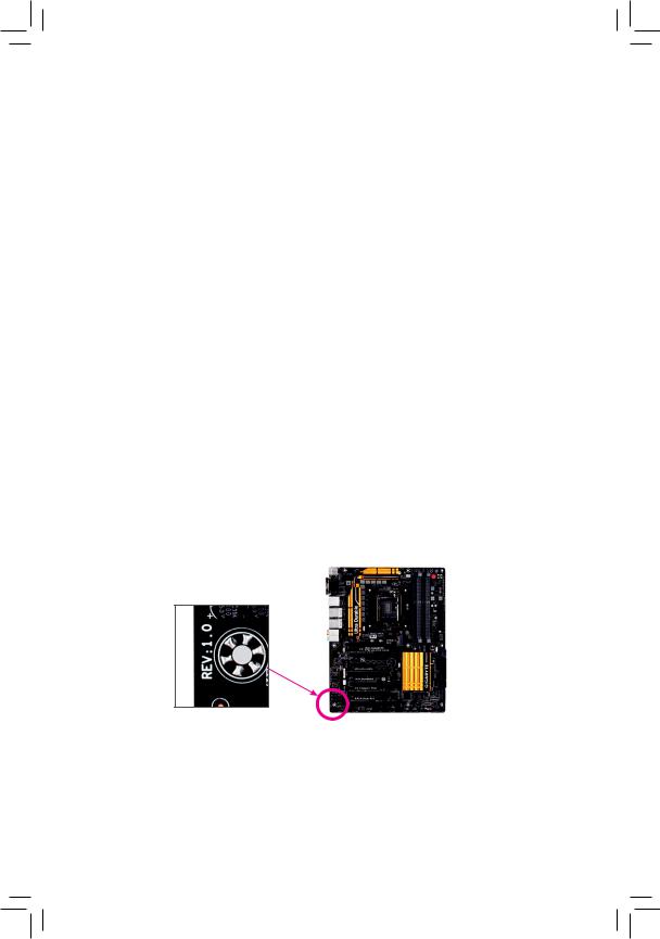
Identifying Your Motherboard Revision
The revision number on your motherboard looks like this: «REV: X.X.» For example, «REV: 1.0» means the revision of the motherboard is 1.0. Check your motherboard revision before updating motherboard BIOS, drivers, or when looking for technical information.
Example:

Table of Contents
|
Box Contents…………………………………………………………………………………………………….. |
6 |
||
|
Optional Items…………………………………………………………………………………………………… |
6 |
||
|
GA-Z97X-SLI Motherboard Layout………………………………………………………………………. |
7 |
||
|
GA-Z97X-SLI Motherboard Block Diagram……………………………………………………………. |
8 |
||
|
Chapter 1 Hardware Installation………………………………………………………………………….. |
9 |
||
|
1-1 |
Installation Precautions…………………………………………………………………………. |
9 |
|
|
1-2 |
Product Specifications………………………………………………………………………… |
10 |
|
|
1-3 Installing the CPU and CPU Cooler………………………………………………………. |
13 |
||
|
1-3-1 |
Installing the CPU……………………………………………………………………………………… |
13 |
|
|
1-3-2 Installing the CPU Cooler……………………………………………………………………………. |
15 |
||
|
1-4 |
Installing the Memory………………………………………………………………………….. |
16 |
|
|
1-4-1 Dual Channel Memory Configuration……………………………………………………………. |
16 |
||
|
1-4-2 |
Installing a Memory……………………………………………………………………………………. |
17 |
|
|
1-5 Installing an Expansion Card……………………………………………………………….. |
18 |
||
|
1-6 Setting up AMD CrossFire™/NVIDIA® SLI™ Configuration…………………………. |
19 |
||
|
1-7 |
Back Panel Connectors………………………………………………………………………. |
20 |
|
|
1-8 |
Internal Connectors……………………………………………………………………………. |
22 |
|
|
Chapter 2 BIOS Setup……………………………………………………………………………………… |
32 |
||
|
2-1 |
Startup Screen…………………………………………………………………………………… |
33 |
|
|
2-2 |
The Main Menu………………………………………………………………………………….. |
34 |
|
|
2-3 |
M.I.T…………………………………………………………………………………………………. |
37 |
|
|
2-4 |
System Information…………………………………………………………………………….. |
48 |
|
|
2-5 |
BIOS Features…………………………………………………………………………………… |
49 |
|
|
2-6 |
Peripherals………………………………………………………………………………………… |
53 |
|
|
2-7 |
Power Management……………………………………………………………………………. |
57 |
|
|
2-8 |
Save & Exit……………………………………………………………………………………….. |
59 |
— 4 —

|
Chapter 3 |
Configuring SATA Hard Drive(s)…………………………………………………………. |
60 |
|
|
3-1 |
Configuring SATA Controllers………………………………………………………………. |
60 |
|
|
3-2 |
Installing the SATA RAID/AHCI Driver and Operating System………………….. |
72 |
|
|
Chapter 6 |
Appendix…………………………………………………………………………………………. |
76 |
|
|
Drivers Installation……………………………………………………………………………………….. |
76 |
||
|
Regulatory Statements…………………………………………………………………………………. |
77 |
||
|
Contact Us………………………………………………………………………………………………….. |
79 |
— 5 —
Box Contents
;; GA-Z97X-SLI motherboard ;; Motherboard driver disk ;; User’s Manual
;; Two SATA cables ;; I/O Shield
;; One 2-Way SLI bridge connector
The box contents above are for reference only and the actual items shall depend on the product package you obtain. The box contents are subject to change without notice.
Optional Items
2-port USB 2.0 bracket (Part No. 12CR1-1UB030-6*R)eSATA bracket (Part No. 12CF1-3SATPW-4*R)
3.5″ Front Panel with 2 USB 3.0/2.0 ports (Part No. 12CR1-FPX582-2*R)HDMI-to-DVI adapter (Part No. 12CT2-HDMI01-1*R)
LPT port cable (Part No. 12CF1-1LP001-0*R)COM port cable (Part No. 12CF1-1CM001-3*R)
— 6 —
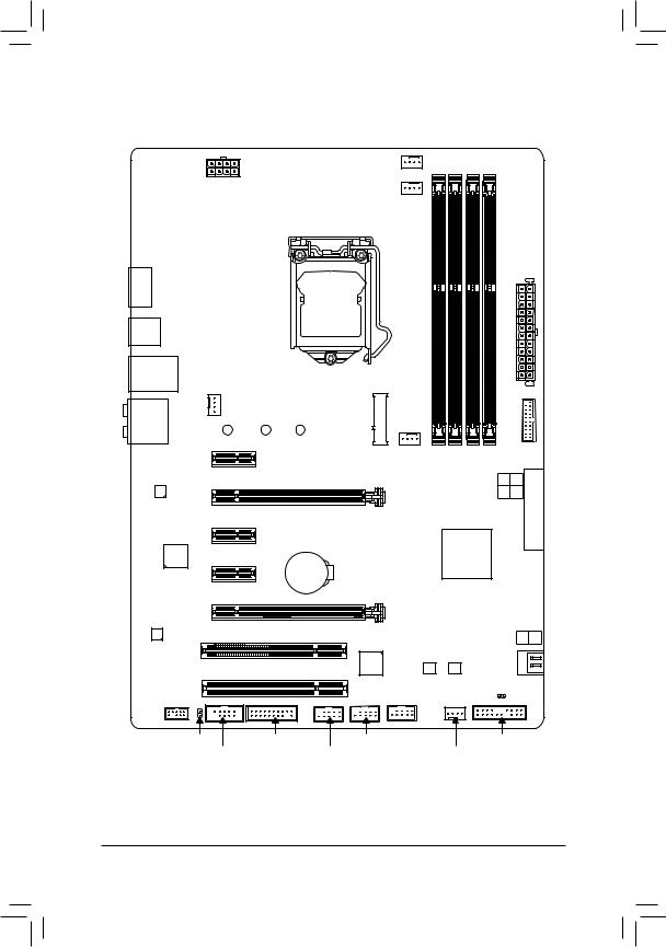
GA-Z97X-SLI Motherboard Layout
|
KB_MS_ |
USB |
CPU_FAN |
|||||
|
ATX_12V_2X4 |
CPU_OPT |
||||||
|
DVI |
|||||||
|
VGA |
LGA1150 |
||||||
ATX
HDMI
R_USB30
USB30_LAN
|
SYS_FAN1 |
|
|
AUDIO |
M.2 |
|
PCIEX1_1 |
|
|
Intel® |
GA-Z97X-SLI |
|
GbE LAN |
PCIEX16 |
|
PCIEX1_2 |
|
|
iTE® |
|
|
Super I/O |
PCIEX1_3 |
|
BAT |
SYS_FAN3
DDR3_1
DDR3_3
DDR3_2
DDR3_4
Intel® Z97
|
F USB30 |
|
|
2 4 |
|
|
3 5 |
EXPRESS |
|
SATA3 |
|
|
SATA_ |
|
PCIEX8 |
||||
|
CODEC |
SATA3 1 0 |
|||
|
PCI1 |
||||
|
PCIe to |
||||
|
PCI2 |
PCI Bridge |
|||
|
B_BIOS M_BIOS |
||||
|
F_AUDIO |
F_USB1 |
CLR_CMOS |
||
|
SPDIF_O |
LPT |
F_USB2 |
F_PANEL |
|
|
COMA |
F_USB3 |
SYS_FAN2 |
— 7 —
GA-Z97X-SLI Motherboard Block Diagram
|
2 PCI Express x8 |
1 PCI Express x16 |
or
PCIe CLK
(100 MHz)
HDMI
DVI-D
 x16
x16  x16
x16
Switch
PCI Express Bus
CPU CLK+/- (100 MHz)
LGA1150
CPU DDR3 1600/1333 MHz
Dual Channel Memory
FDI
DMI 2.0
|
3 PCI Express x1 |
D-Sub |
Switch |
or |
M.2 |
|||
|
SATA Express |
|||||||
|
or |
|||||||
|
Dual BIOS |
2 SATA 6Gb/s |
||||||
|
x1 |
x1 |
x1 |
PCI Express Bus |
4 SATA 6Gb/s |
|||
|
x1 |
x1 |
Intel® Z97 |
6 USB 3.0/2.0 |
||||
|
PCIe CLK |
|||||||
|
Intel® |
PCIe to |
||||||
|
(100 MHz) |
|||||||
|
GbE LAN |
PCI Bridge |
8 USB 2.0/1.1 |
|||||
|
RJ45 |
|||||||
|
PCI Bus |
LAN |
LPC |
|||||
|
COM |
|||||||
|
Bus |
iTE® |
LPT |
|||||
|
Super I/O |
|||||||
|
CODEC |
PS/2 KB/Mouse |
||||||
|
Out Out Out |
MIC |
Line |
Out |
|
Out |
|||
|
In |
|||
|
Speaker Speaker Speaker |
Line |
S/PDIF |
|
|
Rear Center/Subwoofer Side |

 For detailed product information/limitation(s), refer to «1-2 Product Specifications.»
— 8 —

Chapter 1 Hardware Installation
1-1 Installation Precautions
The motherboard contains numerous delicate electronic circuits and components which can become damaged as a result of electrostatic discharge (ESD). Prior to installation, carefully read the user’s manual and follow these procedures:
•• Prior to installation, make sure the chassis is suitable for the motherboard.
•• Prior to installation, do not remove or break motherboard S/N (Serial Number) sticker or warranty sticker provided by your dealer. These stickers are required for warranty validation.
•• Always remove the AC power by unplugging the power cord from the power outlet before installing or removing the motherboard or other hardware components.
•• When connecting hardware components to the internal connectors on the motherboard, make sure they are connected tightly and securely.
•• When handling the motherboard, avoid touching any metal leads or connectors.
•• It is best to wear an electrostatic discharge (ESD) wrist strap when handling electronic components such as a motherboard, CPU or memory. If you do not have an ESD wrist strap, keep your hands dry and first touch a metal object to eliminate static electricity.
•• Prior to installing the motherboard, please have it on top of an antistatic pad or within an electrostatic shielding container.
•• Before unplugging the power supply cable from the motherboard, make sure the power supply has been turned off.
•• Before turning on the power, make sure the power supply voltage has been set according to the local voltage standard.
•• Before using the product, please verify that all cables and power connectors of your hardware components are connected.
•• To prevent damage to the motherboard, do not allow screws to come in contact with the motherboard circuit or its components.
•• Make sure there are no leftover screws or metal components placed on the motherboard or within the computer casing.
•• Do not place the computer system on an uneven surface.
•• Do not place the computer system in a high-temperature environment.
•• Turning on the computer power during the installation process can lead to damage to system components as well as physical harm to the user.
•• If you are uncertain about any installation steps or have a problem related to the use of the product, please consult a certified computer technician.
|
— 9 — |
Hardware Installation |
|
1-2 |
Product Specifications |
|
|
CPU |
Support for Intel® Core™ i7 processors/Intel® Core™ i5 processors/ |
|
|
Intel® Core™ i3 processors/Intel® Pentium® processors/ |
||
|
Intel® Celeron® processors in the LGA1150 package |
||
|
(Go to GIGABYTE’s website for the latest CPU support list.) |
||
|
L3 cache varies with CPU |
||
|
Chipset |
Intel® Z97 Express Chipset |
|
|
Memory |
4 x DDR3 DIMM sockets supporting up to 32 GB of system memory |
* DuetoaWindows32-bitoperatingsystemlimitation,whenmorethan4GBofphysical memory is installed, the actual memory size displayed will be less than the size of the physical memory installed.
Dual channel memory architecture
Support for DDR3 1600/1333 MHz memory modules
Support for non-ECC memory modules
Support for Extreme Memory Profile (XMP) memory modules
(GotoGIGABYTE’swebsiteforthelatestsupportedmemoryspeedsandmemory modules.)
|
Onboard |
Integrated Graphics Processor: |
||
|
Graphics |
— |
1 x D-Sub port, supporting a maximum resolution of 1920×1200@60Hz |
|
|
— |
1 x DVI-D port, supporting a maximum resolution of 1920×1200@60Hz |
||
|
* The DVI-D port does not support D-Sub connection by adapter. |
|||
|
— |
1 x HDMI port, supporting a maximum resolution of 4096×2160@24Hz or |
||
|
2560×1600@60Hz |
|||
|
* Support for HDMI 1.4a version. |
|||
|
— |
Support for up to 3 displays at the same time |
||
|
— |
Maximum shared memory of 1 GB |
||
|
Audio |
Realtek® ALC1150 codec |
||
|
High Definition Audio |
|||
|
2/4/5.1/7.1-channel |
|||
|
Support for S/PDIF Out |
|||
|
LAN |
Intel® GbE LAN chip (10/100/1000 Mbit) |
||
|
Expansion Slots |
1 x PCI Express x16 slot, running at x16 (PCIEX16) |
||
|
* For optimum performance, if only one PCI Express graphics card is to be installed, |
|||
|
be sure to install it in the PCIEX16 slot. |
|||
|
1 x PCI Express x16 slot, running at x8 (PCIEX8) |
|||
|
* The PCIEX8 slot shares bandwidth with the PCIEX16 slot. When the PCIEX8 slot |
|||
|
is populated, the PCIEX16 slot will operate at up to x8 mode. |
|||
|
(The PCIEX16 and PCIEX8 slots conform to PCI Express 3.0 standard.) |
|||
|
3 x PCI Express x1 slots |
|||
|
(The PCI Express x1 slots conform to PCI Express 2.0 standard.) |
|||
|
2 x PCI slots |
|||
|
Multi-Graphics |
Support for 2-Way AMD CrossFire™/2-Way NVIDIA® SLI™ Technology |
||
|
Technology |
|
Hardware Installation |
— 10 — |
![]()
Storage Interface Chipset:
— 1 x M.2 PCIe connector
— 1 x SATA Express connector — 6 x SATA 6Gb/s connectors
(M.2, SATA Express, and SATA3 4/5 connectors can only be used one at a time. TheSATA34/5connectorswillbecomeunavailablewhenanM.2SSDisinstalled.)
—Support for RAID 0, RAID 1, RAID 5, and RAID 10
|
USB |
Chipset: |
|
|
— 6 USB 3.0/2.0 ports (4 ports on the back panel, 2 ports available through the |
||
|
internal USB header) |
||
|
— 8 USB 2.0/1.1 ports (2 ports on the back panel, 6 ports available through the |
||
|
internal USB headers) |
||
|
Internal |
1 x 24-pin ATX main power connector |
|
|
Connectors |
1 x 8-pin ATX 12V power connector |
|
|
1 x M.2 PCIe connector |
||
|
1 x SATA Express connector |
||
|
6 x SATA 6Gb/s connectors |
||
|
1 x CPU fan header |
||
|
1 x water cooling fan header (CPU_OPT) |
||
|
3 x system fan headers |
||
|
1 x front panel header |
||
|
1 x front panel audio header |
||
|
1 x S/PDIF Out header |
||
|
1 x USB 3.0/2.0 header |
||
|
3 x USB 2.0/1.1 headers |
||
|
1 x serial port header |
||
|
1 x parallel port header |
||
|
1 x Clear CMOS jumper |
||
|
Back Panel |
1 x PS/2 keyboard/mouse port |
|
|
Connectors |
1 x D-Sub port |
|
|
1 x DVI-D port |
||
|
1 x HDMI port |
||
|
4 x USB 3.0/2.0 ports |
||
|
2 x USB 2.0/1.1 ports |
||
|
1 x RJ-45 port |
||
|
6xaudiojacks(Center/SubwooferSpeakerOut,RearSpeakerOut,SideSpeaker |
||
|
Out, Line In, Line Out, Mic In) |
||
|
I/O Controller |
iTE® I/O Controller Chip |
|
|
Hardware |
System voltage detection |
|
|
Monitor |
CPU/System temperature detection |
|
|
CPU/CPU OPT/System fan speed detection |
||
|
CPU/System overheating warning |
||
|
CPU/CPU OPT/System fan fail warning |
||
|
CPU/CPU OPT/System fan speed control |
*Whether the fan speed control function is supported will depend on the cooler you install.
|
— 11 — |
Hardware Installation |
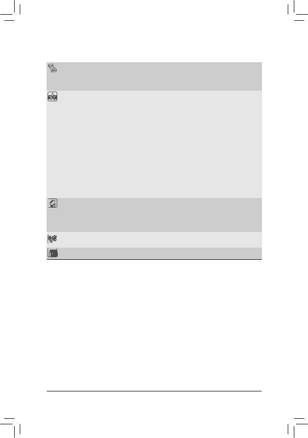
|
BIOS |
2 x 64 Mbit flash |
|||
|
Use of licensed AMI UEFI BIOS |
||||
|
Support for DualBIOS™ |
||||
|
PnP 1.0a, DMI 2.7, SM BIOS 2.7, ACPI 2.0 |
||||
|
Unique Features |
Support for APP Center |
|||
|
* Available applications in APP Center may differ by motherboard model. Supported |
||||
|
functions of each application may also differ depending on motherboard |
||||
|
specifications. |
||||
|
— |
@BIOS |
|||
|
— |
EasyTune |
|||
|
— |
EZ Setup |
|||
|
— |
Fast Boot |
|||
|
— |
ON/OFF Charge |
|||
|
— |
Smart TimeLock |
|||
|
— |
Smart Recovery 2 |
|||
|
— |
System Information Viewer |
|||
|
— |
USB Blocker |
|||
|
Support for Q-Flash |
||||
|
Support for Smart Switch |
||||
|
Support for Xpress Install |
||||
|
Bundled |
Norton® Internet Security (OEM version) |
|||
|
Software |
Intel® Rapid Start Technology |
|||
|
Intel® Smart Connect Technology |
||||
|
Intel® Smart Response Technology |
||||
|
cFosSpeed |
||||
|
Operating |
Support for Windows 8.1/8/7 |
|||
|
System |
||||
|
Form Factor |
ATX Form Factor; 30.5cm x 21.4cm |
*GIGABYTE reserves the right to make any changes to the product specifications and product-related information without prior notice.
*Please visit the Support & DownloadsUtility page on GIGABYTE’s website to check the supported operating system(s) for the software listed in the «Unique Features» and «Bundled Software» columns.
|
Hardware Installation |
— 12 — |
|
1-3 |
Installing the CPU and CPU Cooler |
|
|
Read the following guidelines before you begin to install the CPU: |
||
|
•• |
Make sure that the motherboard supports the CPU. |
|
|
(Go to GIGABYTE’s website for the latest CPU support list.) |
||
|
•• |
Always turn off the computer and unplug the power cord from the power outlet before installing the |
|
|
CPU to prevent hardware damage. |
||
|
•• |
Locate the pin one of the CPU. The CPU cannot be inserted if oriented incorrectly. (Or you may |
|
|
locate the notches on both sides of the CPU and alignment keys on the CPU socket.) |
||
|
•• |
Apply an even and thin layer of thermal grease on the surface of the CPU. |
|
|
•• |
Do not turn on the computer if the CPU cooler is not installed, otherwise overheating and damage |
|
|
of the CPU may occur. |
||
|
•• |
Set the CPU host frequency in accordance with the CPU specifications. It is not recommended |
|
|
that the system bus frequency be set beyond hardware specifications since it does not meet the |
||
|
standard requirements for the peripherals. If you wish to set the frequency beyond the standard |
||
|
specifications, please do so according to your hardware specifications including the CPU, graphics |
||
|
card, memory, hard drive, etc. |
1-3-1 Installing the CPU
A. Locate the alignment keys on the motherboard CPU socket and the notches on the CPU.
|
LGA1150 CPU Socket |
|
|
Alignment |
Alignment |
|
Key |
Key |
Pin One Corner of the CPU Socket
Triangle Pin One Marking on the CPU
|
— 13 — |
Hardware Installation |
B. Follow the steps below to correctly install the CPU into the motherboard CPU socket.
•• Before installing the CPU, make sure to turn off the computer and unplug the power cord from the power outlet to prevent damage to the CPU.
•• To protect the socket contacts, do not remove the protective plastic cover unless the CPU is inserted into the CPU socket. Save the cover properly and replace it if the CPU is removed.
Step 1:
Gently press the CPU socket lever handle down and away from the socket with your finger. Then completely lift the CPU socket lever and the metal load plate/plastic cover will be lifted as well.
Step 3:
Once the CPU is properly inserted, carefully replace the load plate. When replacing the load plate, make sure the front end of the load plate is under the shoulder screw. Then press the CPU socket lever. The protective plastic cover may pop off from the load plate during the process of engaging the lever. Remove the cover. (Save the cover properly and always replace it when the
CPU is not installed.)
Step 2:
Hold the CPU with your thumb and index fingers. Align the CPU pin one marking (triangle) with the pinonecorneroftheCPUsocket(oryoumayalign the CPU notches with the socket alignment keys) and gently insert the CPU into position.
Step 4:
Finally, secure the lever under its retention tab to complete the installation of the CPU.
NOTE:
Hold the CPU socket lever by the handle, not the lever base portion.
|
Hardware Installation |
— 14 — |
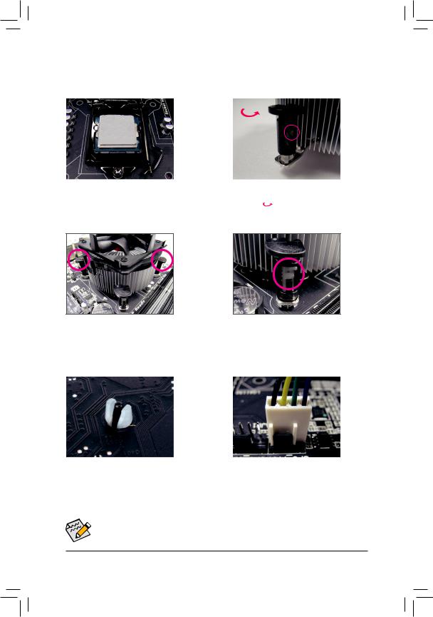
1-3-2 Installing the CPU Cooler
Follow the steps below to correctly install the CPU cooler on the motherboard. (The following procedure uses Intel® boxed cooler as the example cooler.)
|
Male |
|||||||||
|
Direction of |
Push Pin |
||||||||
|
the Arrow Sign |
The Top |
||||||||
|
on the Male |
|||||||||
|
of Female |
|||||||||
|
Push Pin |
|||||||||
|
Push Pin |
|||||||||
|
Female |
|||||||||
|
Push Pin |
|||||||||
|
Step 1: |
Step 2: |
||||||||
|
Apply an even and thin layer of thermal grease on |
Before installing the cooler, note the direction of the |
||||||||
|
the surface of the installed CPU. |
arrow sign |
onthemalepushpin.(Turningthe |
push pin along the direction of arrow is to remove the cooler, on the contrary, is to install.)
|
Step 3: |
Step 4: |
||
|
Place the cooler atop the CPU, aligning the |
You should hear a «click» when pushing down each |
||
|
four push pins through the pin holes on the |
push pin. Check that the Male and Female push |
||
|
motherboard. Push down on the push pins |
pins are joined closely. |
||
|
diagonally. |
(Refer to your CPU cooler installation manual for |
||
|
instructions on installing the cooler.) |
|||
|
Step 5: |
Step 6: |
|
After the installation, check the back of the |
Finally, attach the power connector of the CPU |
|
motherboard. If the push pin is inserted as the |
cooler to the CPU fan header (CPU_FAN) on the |
|
picture above shows, the installation is complete. |
motherboard. |
 Use extreme care when removing the CPU cooler because the thermal grease/tape between the CPU cooler and CPU may adhere to the CPU. Inadequately removing the CPU cooler may damage the CPU.
— 15 — Hardware Installation
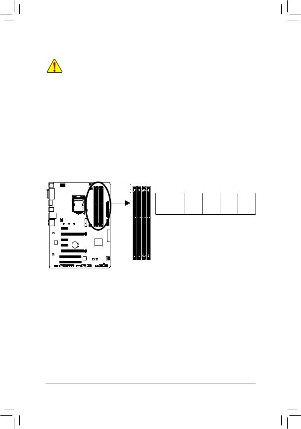
1-4 Installing the Memory
Read the following guidelines before you begin to install the memory:
•• Make sure that the motherboard supports the memory. It is recommended that memory of the same capacity, brand, speed, and chips be used.
(Go to GIGABYTE’s website for the latest supported memory speeds and memory modules.)
•• Always turn off the computer and unplug the power cord from the power outlet before installing the memory to prevent hardware damage.
•• Memory modules have a foolproof design. A memory module can be installed in only one direction. If you are unable to insert the memory, switch the direction.
1-4-1 Dual Channel Memory Configuration
This motherboard provides four DDR3 memory sockets and supports Dual Channel Technology. After the memory is installed, the BIOS will automatically detect the specifications and capacity of the memory. Enabling
Dual Channel memory mode will double the original memory bandwidth.
The four DDR3 memory sockets are divided into two channels and each channel has two memory sockets as following:
Channel A: DDR3_2, DDR3_4Channel B: DDR3_1, DDR3_3
Dual Channel Memory Configurations Table
|
DDR3_4 DDR3_2 |
DDR3_3 |
DDR3_1 |
||
|
Two Modules |
— — |
DS/SS |
— — |
DS/SS |
|
DS/SS |
— — |
DS/SS |
— — |
|
|
Four Modules |
DS/SS |
DS/SS |
DS/SS |
DS/SS |
(SS=Single-Sided, DS=Double-Sided, «- -«=No Memory)
DDR3_1
DDR3_3
DDR3_2
DDR3_4
Due to CPU limitations, read the following guidelines before installing the memory in Dual Channel mode.
1.Dual Channel mode cannot be enabled if only one DDR3 memory module is installed.
2.When enabling Dual Channel mode with two or four memory modules, it is recommended that memory of the same capacity, brand, speed, and chips be used and installed in the same colored DDR3 sockets. For optimum performance, when enabling Dual Channel mode with two memory modules, we recommend that you install them in the DDR3_1 and DDR3_2 sockets.
|
Hardware Installation |
— 16 — |
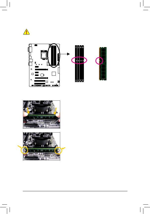
1-4-2 Installing a Memory
Before installing a memory module, make sure to turn off the computer and unplug the power cord from the power outlet to prevent damage to the memory module. DDR3 and DDR2 DIMMs are not compatible to each other or DDR DIMMs. Be sure to install DDR3 DIMMs on this motherboard.
Notch
DDR3 DIMM
ADDR3 memory module has a notch, so it can only fit in one direction. Follow the steps below to correctly install your memory modules in the memory sockets.
Step 1:
Note the orientation of the memory module. Spread the retaining clips at both ends of the memory socket. Place the memory module on the socket. As indicated in the picture on the left, place your fingers on the top edge of the memory, push down on the memory and insert it vertically into the memory socket.
Step 2:
The clips at both ends of the socket will snap into place when the memory module is securely inserted.
|
— 17 — |
Hardware Installation |
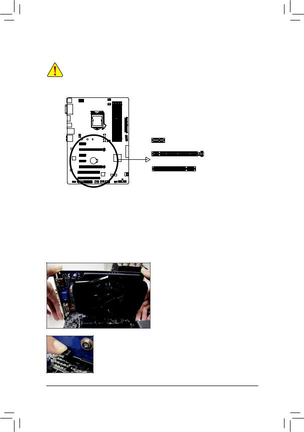
1-5 Installing an Expansion Card
Read the following guidelines before you begin to install an expansion card:
•• Make sure the motherboard supports the expansion card. Carefully read the manual that came with your expansion card.
•• Always turn off the computer and unplug the power cord from the power outlet before installing an expansion card to prevent hardware damage.
PCI Express x1 Slot
PCI Express x16 Slot
 PCI Slot
Follow the steps below to correctly install your expansion card in the expansion slot.
1.Locate an expansion slot that supports your card. Remove the metal slot cover from the chassis back panel.
2.Align the card with the slot, and press down on the card until it is fully seated in the slot.
3.Make sure the metal contacts on the card are completely inserted into the slot.
4.Secure the card’s metal bracket to the chassis back panel with a screw.
5.After installing all expansion cards, replace the chassis cover(s).
6.Turn on your computer. If necessary, go to BIOS Setup to make any required BIOS changes for your expansion card(s).
7.Install the driver provided with the expansion card in your operating system.
Example: Installing and Removing a PCI Express Graphics Card:
•• Installing a Graphics Card:
Gently push down on the top edge of the card until it is fully inserted into the PCI Express slot. Make sure the card is securely seated in the slot and does not rock.
•• Removing the Card:
Gently push back on the lever on the slot and then lift the card straight out from the slot.
|
Hardware Installation |
— 18 — |
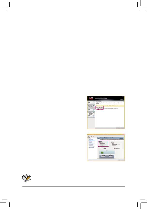
1-6 Setting up AMD CrossFire™/NVIDIA® SLI™ Configuration
A.System Requirements
— Windows 8.1/8/7 operating system
— A CrossFire/SLI-supported motherboard with two PCI Express x16 slots and correct driver — Two CrossFire/SLI-ready graphics cards of identical brand and chip and correct driver
— CrossFire (Note)/SLI bridge connector
— A power supply with sufficient power is recommended (Refer to the manual of your graphics cards for the power requirement)
B.Connecting the Graphics Cards
Step 1:
Observe the steps in «1-5 Installing an Expansion Card» and install CrossFire/SLI graphics cards on the PCIEX16 and PCIEX8 slots.
Step 2:
Insert the CrossFire (Note)/SLI bridge connectors in the CrossFire/SLI gold edge connectors on top of the cards.
Step 3:
Plug the display cable into the graphics card on the PCIEX16 slot.
C. Configuring the Graphics Card Driver
C-1. To Enable CrossFire Function
After installing the graphics card driver in the operating system, go to the AMD Catalyst Control Center. Browse to PerformanceAMD CrossFireX™ and ensure the Enable AMD CrossFireX check box is selected. and click Apply.
C-2. To Enable SLI Function
After installing the graphics card driver in the operating system, go to the NVIDIA Control Panel. Browse to the ConfigureSLI,Surround, Physx screen and ensure Maximize 3D performance is enabled.
(Note) The bridge connector(s) may be needed or not depending on your graphics cards.
Procedure and driver screen for enabling CrossFire/SLI technology may differ by graphics cards and driver version. Refer to the manual that came with your graphics cards for more information about enabling CrossFire/SLI technology.
|
— 19 — |
Hardware Installation |
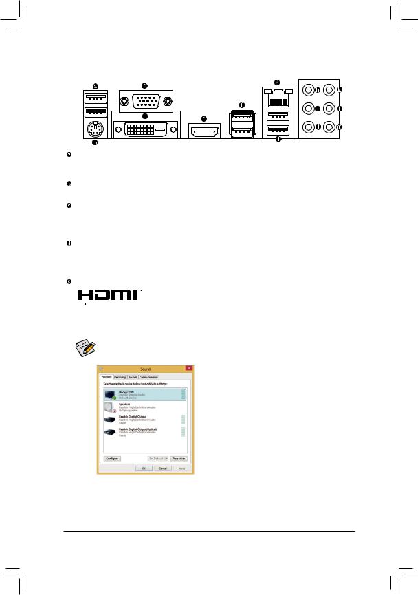
1-7 Back Panel Connectors
USB 2.0/1.1 Port
The USB port supports the USB 2.0/1.1 specification. Use this port for USB devices such as a USB keyboard/mouse, USB printer, USB flash drive and etc.
PS/2 Keyboard/Mouse Port
Use this port to connect a PS/2 mouse or keyboard.
D-Sub Port
The D-Sub port supports a 15-pin D-Sub connector and supports a maximum resolution of 1920×1200@60Hz (the actual resolutions supported depend on the monitor being used). Connect a monitor that supports
D-Sub connection to this port.
DVI-D Port (Note)
The DVI-D port conforms to the DVI-D specification and supports a maximum resolution of 1920×1200 @60Hz (the actual resolutions supported depend on the monitor being used). Connect a monitor that supports DVI-D connection to this port.
HDMI Port
The HDMI port is HDCP compliant and supports Dolby True HD and DTS HD


 MasterAudioformats.Italsosupportsupto192KHz/24bit8-channelLPCMaudio output. You can use this port to connect your HDMI-supported monitor. The maximum supported resolution is 4096×2160@24Hz or 2560×1600@60Hz, but the actual resolutions supported are dependent on the monitor being used.
After installing the HDMI device, make sure to set the default sound playback device to HDMI.
(The item name may differ depending on your operating system. The screenshot below is from Windows 8.1.)
In Windows 8.1, select Apps>Control Panel>Hardware and
Sound>Sound>Playback, set Intel(R) Display Audio to the default playback device.
Triple-Display Configurations for the Onboard Graphics:
Triple-display configurations are supported after you install motherboard drivers in OS. Only dual-display configurations are supported during the BIOS Setup or POST process.
(Note) The DVI-D port does not support D-Sub connection by adapter.
|
Hardware Installation |
— 20 — |
![]()
USB 3.0/2.0 Port
The USB 3.0 port supports the USB 3.0 specification and is compatible to the USB 2.0/1.1 specification. Use this port for USB devices such as a USB keyboard/mouse, USB printer, USB flash drive and etc.
RJ-45 LAN Port
The Gigabit Ethernet LAN port provides Internet connection at up to 1 Gbps data rate. The following describes the states of the LAN port LEDs.
|
Connection/ |
Connection/Speed LED: |
Activity LED: |
|||||||||||||||||
|
Speed LED |
Activity LED |
||||||||||||||||||
|
State |
Description |
State |
Description |
||||||||||||||||
|
Orange |
1 Gbps data rate |
Blinking |
Data transmission or receiving is occurring |
||||||||||||||||
|
Green |
100 Mbps data rate |
On |
No data transmission or receiving is |
||||||||||||||||
|
Off |
10 Mbps data rate |
occurring |
|||||||||||||||||
|
LAN Port |
|||||||||||||||||||
Center/Subwoofer Speaker Out Jack (Orange)
Use this audio jack to connect center/subwoofer speakers in a 5.1/7.1-channel audio configuration.
Rear Speaker Out Jack (Black)
This jack can be used to connect front speakers in a 4/5.1/7.1-channel audio configuration.
Side Speaker Out Jack (Gray)
Use this audio jack to connect side speakers in a 7.1-channel audio configuration.
Line In Jack (Blue)
The line in jack. Use this audio jack for line in devices such as an optical drive, walkman, etc.
Line Out Jack (Green)
The line out jack. This jack supports audio amplifying function. For better sound quality, it is recom-mended that you connect your headphone/speaker to this jack (actual effects may vary by the device being used).
Use this audio jack for a headphone or 2-channel speaker. This jack can be used to connect front speakers in a 4/5.1/7.1-channel audio configuration.
Mic In Jack (Pink)
The Mic in jack. Microphones must be connected to this jack.
The audio jacks can be reconfigured to perform different functions via the audio software (supported functions may vary based on hardware specification). Only microphones still MUST be connected to the default Mic in jack.
•• When removing the cable connected to a back panel connector, first remove the cable from your device and then remove it from the motherboard.
•• When removing the cable, pull it straight out from the connector. Do not rock it side to side to prevent an electrical short inside the cable connector.
|
— 21 — |
Hardware Installation |
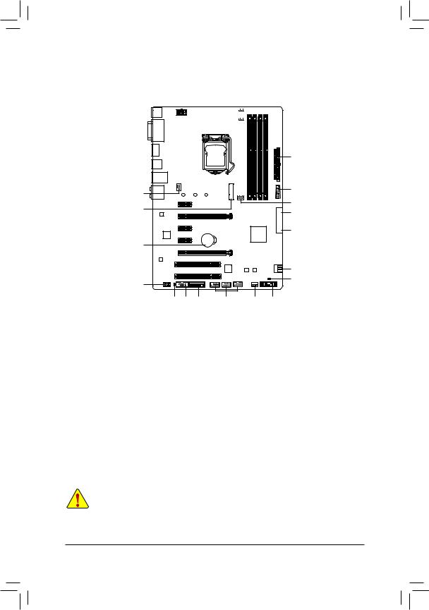
1-8 Internal Connectors
|
1 |
5 |
3 |
||||
|
2 |
|||||
|
4 |
12 |
||||
|
8 |
4 |
||||
|
7 |
|||||
|
6 |
|||||
|
16 |
|||||
|
7 |
|||||
|
10 |
17 |
||||
|
11 |
14 |
15 |
13 |
4 |
9 |
|
1) |
ATX_12V_2X4 |
10) |
F_AUDIO |
|
2) |
ATX |
11) |
SPDIF_O |
|
3) |
CPU_FAN |
12) |
F_USB30 |
|
4) |
SYS_FAN1/2/3 |
13) |
F_USB1/F_USB2/F_USB3 |
|
5) |
CPU_OPT |
14) |
COMA |
|
6) |
SATA_EXPRESS |
15) |
LPT |
|
7) |
SATA3 0/1/2/3/4/5 |
16) |
BAT |
|
|
M.2 |
17) |
CLR_CMOS |
|
9) |
F_PANEL |
Read the following guidelines before connecting external devices:
•• First make sure your devices are compliant with the connectors you wish to connect.
•• Before installing the devices, be sure to turn off the devices and your computer. Unplug the power cord from the power outlet to prevent damage to the devices.
•• After installing the device and before turning on the computer, make sure the device cable has been securely attached to the connector on the motherboard.
|
Hardware Installation |
— 22 — |
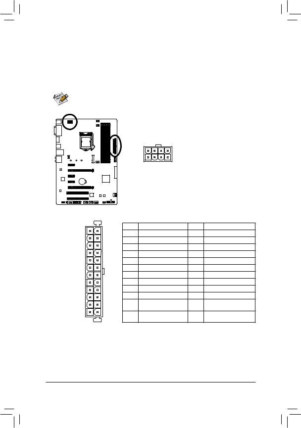
1/2) ATX_12V_2X4/ATX (2×4 12V Power Connector and 2×12 Main Power Connector)
With the use of the power connector, the power supply can supply enough stable power to all the components on the motherboard. Before connecting the power connector, first make sure the power supply is turned off and all devices are properly installed. The power connector possesses a foolproof design. Connect the power supply cable to the power connector in the correct orientation.
The 12V power connector mainly supplies power to the CPU. If the 12V power connector is not connected, the computer will not start.
To meet expansion requirements, it is recommended that a power supply that can withstand high power consumption be used (500W or greater). If a power supply is used that does not provide the required power, the result can lead to an unstable or unbootable system.
|
ATX_12V_2X4: |
||||
|
Pin No. |
Definition |
|||
|
1 |
GND (Only for 2×4-pin 12V) |
|||
|
2 |
GND (Only for 2×4-pin 12V) |
|||
|
5 |
8 |
3 |
GND |
|
|
4 |
GND |
|||
|
1 |
4 |
|||
|
5 |
+12V (Only for 2×4-pin 12V) |
|||
|
ATX_12V_2X4 |
6 |
+12V (Only for 2×4-pin 12V) |
||
|
7 |
+12V |
|||
|
8 |
+12V |
|
ATX: |
|||
|
Pin No. |
Definition |
Pin No. |
Definition |
|
1 |
3.3V |
13 |
3.3V |
|
2 |
3.3V |
14 |
-12V |
|
3 |
GND |
15 |
GND |
|
4 |
+5V |
16 |
PS_ON (soft On/Off) |
|
5 |
GND |
17 |
GND |
|
6 |
+5V |
18 |
GND |
|
7 |
GND |
19 |
GND |
|
8 |
Power Good |
20 |
-5V |
|
9 |
5VSB (stand by +5V) |
21 |
+5V |
|
10 |
+12V |
22 |
+5V |
|
11 |
+12V (Only for 2×12-pin |
23 |
+5V (Only for 2×12-pin ATX) |
|
ATX) |
|||
|
12 |
3.3V (Only for 2×12-pin |
24 |
GND (Only for 2×12-pinATX) |
|
ATX) |
|
— 23 — |
Hardware Installation |
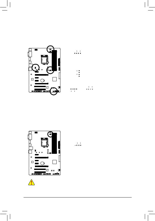
3/4) CPU_FAN/SYS_FAN1/SYS_FAN2/SYS_FAN3 (Fan Headers)
All fan headers on this motherboard are 4-pin. Most fan headers possess a foolproof insertion design.
When connecting a fan cable, be sure to connect it in the correct orientation (the black connector wire is the ground wire). The motherboard supports CPU fan speed control, which requires the use of a CPU fan with fan speed control design. For optimum heat dissipation, it is recommended that a system fan be installed inside the chassis.
|
CPU_FAN: |
||||||||||||||
|
Pin No. |
Definition |
|||||||||||||
|
1 |
1 |
GND |
||||||||||||
|
2 |
+12V |
|||||||||||||
|
CPU_FAN |
||||||||||||||
|
3 |
Sense |
|||||||||||||
|
4 |
Speed Control |
|||||||||||||
|
1 |
SYS_FAN1/2/3: |
|||||||||||||
|
Pin No. |
Definition |
|||||||||||||
|
1 |
GND |
|||||||||||||
|
SYS_FAN1 |
||||||||||||||
|
2 |
+12V / Speed Control |
|||||||||||||
|
3 |
Sense |
|||||||||||||
|
1 |
1 |
4 |
VCC |
|||||||||||
|
SYS_FAN2 |
SYS_FAN3 |
5)CPU_OPT (Water Cooling CPU Fan Header)
The fan header is 4-pin and possesses a foolproof insertion design. When connecting a fan cable, be sure to connect it in the correct orientation (the black connector wire is the ground wire). The speed control function requires the use of a fan with fan speed control design.
|
Pin No. |
Definition |
||||
|
1 |
GND |
||||
|
1 |
2 |
+12V / Speed Control |
|||
|
3 |
Sense |
||||
|
4 |
VCC |
•• Be sure to connect fan cables to the fan headers to prevent your CPU and system from overheating. Overheating may result in damage to the CPU or the system may hang.
•• Thesefanheadersarenotconfigurationjumperblocks.Donotplaceajumpercapontheheaders.
|
Hardware Installation |
— 24 — |
 Loading…