инструкцияGigabyte Z390 Aorus Pro

To reduce the impacts on global warming, the packaging materials of this product
are recyclable and reusable. GIGABYTE works with you to protect the environment.
For more product details, please visit GIGABYTE’s website.
Z390 AORUS
PRO
Z390 AORUS
PRO WIFI
Z390 AORUS PRO
Z390 AORUS PRO
WIFI
User’s Manual
Rev. 1001
12ME-Z39PROW-1001R
Посмотреть инструкция для Gigabyte Z390 Aorus Pro бесплатно. Руководство относится к категории материнские платы, 3 человек(а) дали ему среднюю оценку 9.3. Руководство доступно на следующих языках: английский. У вас есть вопрос о Gigabyte Z390 Aorus Pro или вам нужна помощь? Задайте свой вопрос здесь
- Z390 AORUS PRO (WIFI) Motherboard Layout
- Chapter 1 Hardware Installation
- Chapter 2 BIOS Setup
- Chapter 3 Appendix

Главная
| Gigabyte | |
| Z390 Aorus Pro | Z390 AORUS PRO WIFI | |
| материнская плата | |
| 4719331804299 | |
| английский | |
| Руководство пользователя (PDF), Инструкция по установке (PDF) |
Процессор
| Производитель процессора | Intel |
| Совместимые серии процессоров | Intel Celeron, Intel Core i3, Intel Core i5, Intel Core i7, Intel Pentium |
| Сокет процессора | LGA 1151 (разъем H4) |
Память
| Поддерживаемые типы памяти | DDR4-SDRAM |
| Тип слотов памяти | DIMM |
| Количество слотов памяти | 4 |
| Каналы памяти | Dual-channel |
| Максимальная внутренняя память | 64 GB |
| Небуферизованная память | Да |
| Поддерживаемые объемы модулей памяти | 16GB |
| Поддерживаемые частоты памяти | 2133,2400,2666,2800,3000,3200,3300,3333,3400,3466,3600,3666,3733,3800,3866,4000,4133 MHz |
| без функции коррекции ошибок | Да |
Контроллеры хранения данных
| Поддерживаемые типы накопителей | HDD & SSD |
| Уровни RAID | 0, 1,5, 10 |
Внутренние порты
| Количество параллельных разъемов ATA (PATA) | 0 |
| Разъем питания ATX (24-конт.) | Да |
| EPS разъем питания (8-конт) | Да |
| Разъем вентилятора центрального процессора | Да |
| Количество разъемов вентилятора корпуса | 6 |
| RGB LED контактный разъем | Да |
| Количество разъемов SATA III | 6 |
| Количество разъемов SATA II | 0 |
| Аудиоразъем передней панели | Да |
| Разъем передней панели | Да |
| Разъем выхода S/PDIF | Да |
| Разъемы USB 3.2 Gen 1 (3.1 Gen 1) | 1 |
| Разъемы USB 2.0 | 2 |
| Разъемы USB 3.2 Gen 2 (3.1 Gen 2) | 0 |
| разъемы Thunderbolt | 1 |
| TPM коннектор | Да |
Сеть
| Подключение Ethernet | Да |
| Тип Ethernet интерфейса | Гигабитный Ethernet |
| Wi-Fi | Да |
| Wi-Fi стандартов | 802.11a, Wi-Fi 5 (802.11ac), 802.11b, 802.11g, Wi-Fi 4 (802.11n) |
| Bluetooth | Да |
| Версия Bluetooth | 5.0 |
Свойства
| Семейство чипсета материнской платы | Intel |
| Чипсет материнской платы | Intel Z390 |
| Поддерживаемые операционные системы Windows | Windows 10 |
| Выходные звуковые каналы | 7.1 канала |
| Комплектующие для | ПК |
| Формат материнской платы | ATX |
| Аудио чип | Realtek ALC1220-VB |
BIOS
| Тип BIOS | UEFI AMI |
| Desktop Management Interface (DMI) версия | 2.7 |
| Размер памяти BIOS | 16 Mbit |
| Версия ACPI | 5.0 |
| Версия BIOS (SMBIOS) | 2.7 |
| Перемычка Clear CMOS | Да |
Прочие свойства
Графический адаптер
| Поддержка технологии параллельной обработки | 2-Way CrossFireX, 2-Way SLI, 3-Way CrossFireX, Quad-GPU CrossFireX, Quad-GPU SLI |
Слоты расширения
| PCI Express x1 слоты | 3 |
| PCI Express x16 слоты | 3 |
| Количество M.2 (M) слотов | 2 |
Порты на задней панели
| Количество портов USB 2.0 | 4 |
| Количество портов USB 3.2 Gen 1 (3.1 Gen 1) Type-A | 3 |
| Количество портов USB 3.2 Gen 1 (3.1 Gen 1) Type-С | 0 |
| Количество портов USB 3.2 Gen 2 (3.1 Gen 2) Type-A | 2 |
| Количество портов USB 3.2 Gen 2 (3.1 Gen 2) Type-С | 1 |
| Количество портов Ethernet LAN ( RJ-45) | 1 |
| Количество HDMI портов | 1 |
| Разъем антенны WiFi-AP | 2 |
| Порт выхода S/PDIF | Да |
| Линейные выходы наушников | 1 |
| Линейный вход микрофона | Да |
| Количество портов eSATA | 0 |
| Количество портов PS/2 | 0 |
| Порты FireWire | 0 |
| Количество портов VGA (D-Sub) | 0 |
| Количество портов DVI-D | 0 |
Особые свойства процессора
| Intel® Optane™ Memory Ready | Да |
Вес и размеры
| Ширина | 305 mm |
| Глубина | 244 mm |
Содержимое упаковки
| Поставляемое ПО | Norton® Internet SecurityncFosSpeed |
показать больше
Не можете найти ответ на свой вопрос в руководстве? Вы можете найти ответ на свой вопрос ниже, в разделе часто задаваемых вопросов о Gigabyte Z390 Aorus Pro.
Какая ширина Gigabyte Z390 Aorus Pro?
Какая толщина Gigabyte Z390 Aorus Pro?
Инструкция Gigabyte Z390 Aorus Pro доступно в русский?
Не нашли свой вопрос? Задайте свой вопрос здесь

To reduce the impacts on global warming, the packaging materials of this product
are recyclable and reusable. GIGABYTE works with you to protect the environment.
For more product details, please visit GIGABYTE’s website.
Z390 AORUS
PRO
Z390 AORUS
PRO WIFI
Z390 AORUS PRO
Z390 AORUS PRO
WIFI
User’s Manual
Rev. 1001
12ME-Z39PROW-1001R
— 2 —
Wireless Module Country Approvals:
Motherboard
Z390 AORUS PRO WIFI
Aug. 31, 2018
Aug. 31, 2018
Motherboard
Z390 AORUS PRO WIFI
Copyright
© 2018 GIGA-BYTE TECHNOLOGY CO., LTD. All rights reserved.
The trademarks mentioned in this manual are legally registered to their respective owners.
Disclaimer
Information in this manual is protected by copyright laws and is the property of GIGABYTE.
Changes to the specications and features in this manual may be made by GIGABYTE without prior notice.
No part of this manual may be reproduced, copied, translated, transmitted, or published in any form or
by any means without GIGABYTE’s prior written permission.
In order to assist in the use of this product, carefully read the User’s Manual.
For product-related information, check on our website at: https://www.gigabyte.com
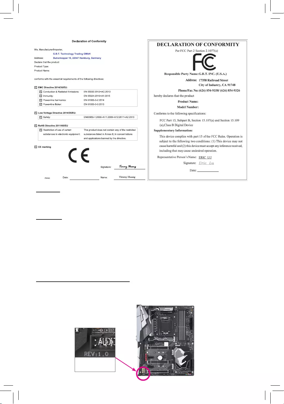
Identifying Your Motherboard Revision
The revision number on your motherboard looks like this: «REV: X.X.» For example, «REV: 1.0″ means
the revision of the motherboard is 1.0. Check your motherboard revision before updating motherboard
BIOS, drivers, or when looking for technical information.
Example:
Motherboard
Z390 AORUS PRO
Aug. 31, 2018
Aug. 31, 2018
Motherboard
Z390 AORUS PRO

— 4 —
Table of Contents
Z390 AORUS PRO (WIFI) Motherboard Layout …………………………………………………….. 5
Chapter 1 Hardware Installation ………………………………………………………………………….6
1-1 Installation Precautions ………………………………………………………………………… 6
1-2 ProductSpecications ………………………………………………………………………….. 7
1-3 Installing the CPU ……………………………………………………………………………… 11
1-4 Installing the Memory …………………………………………………………………………. 11
1-5 Installing an Expansion Card ………………………………………………………………. 12
1-6 Setting up AMD CrossFire™/NVIDIA® SLI™Conguration ………………………… 12
1-7 Back Panel Connectors ………………………………………………………………………. 13
1-8 Internal Connectors ……………………………………………………………………………. 15
Chapter 2 BIOS Setup ……………………………………………………………………………………..25
2-1 Startup Screen ………………………………………………………………………………….. 25
2-2 The Main Menu …………………………………………………………………………………. 26
2-3 M.I.T. ……………………………………………………………………………………………….. 27
2-4 System …………………………………………………………………………………………….. 33
2-5 BIOS ………………………………………………………………………………………………… 34
2-6 Peripherals ……………………………………………………………………………………….. 37
2-7 Chipset …………………………………………………………………………………………….. 40
2-8 Power ………………………………………………………………………………………………. 41
2-9 Save & Exit ……………………………………………………………………………………….. 43
Chapter 3 Appendix …………………………………………………………………………………………44
3-1 ConguringaRAIDSet ………………………………………………………………………. 44
3-2 Installing an Intel® Optane™ Memory …………………………………………………….. 46
3-3 Drivers Installation ……………………………………………………………………………… 48
Regulatory Statements …………………………………………………………………………………. 49
Contact Us …………………………………………………………………………………………………. 56
(Note 1) Only for the Z390 AORUS PRO WIFI.
(Note 2) The chip is on the back of the motherboard.
— 5 —
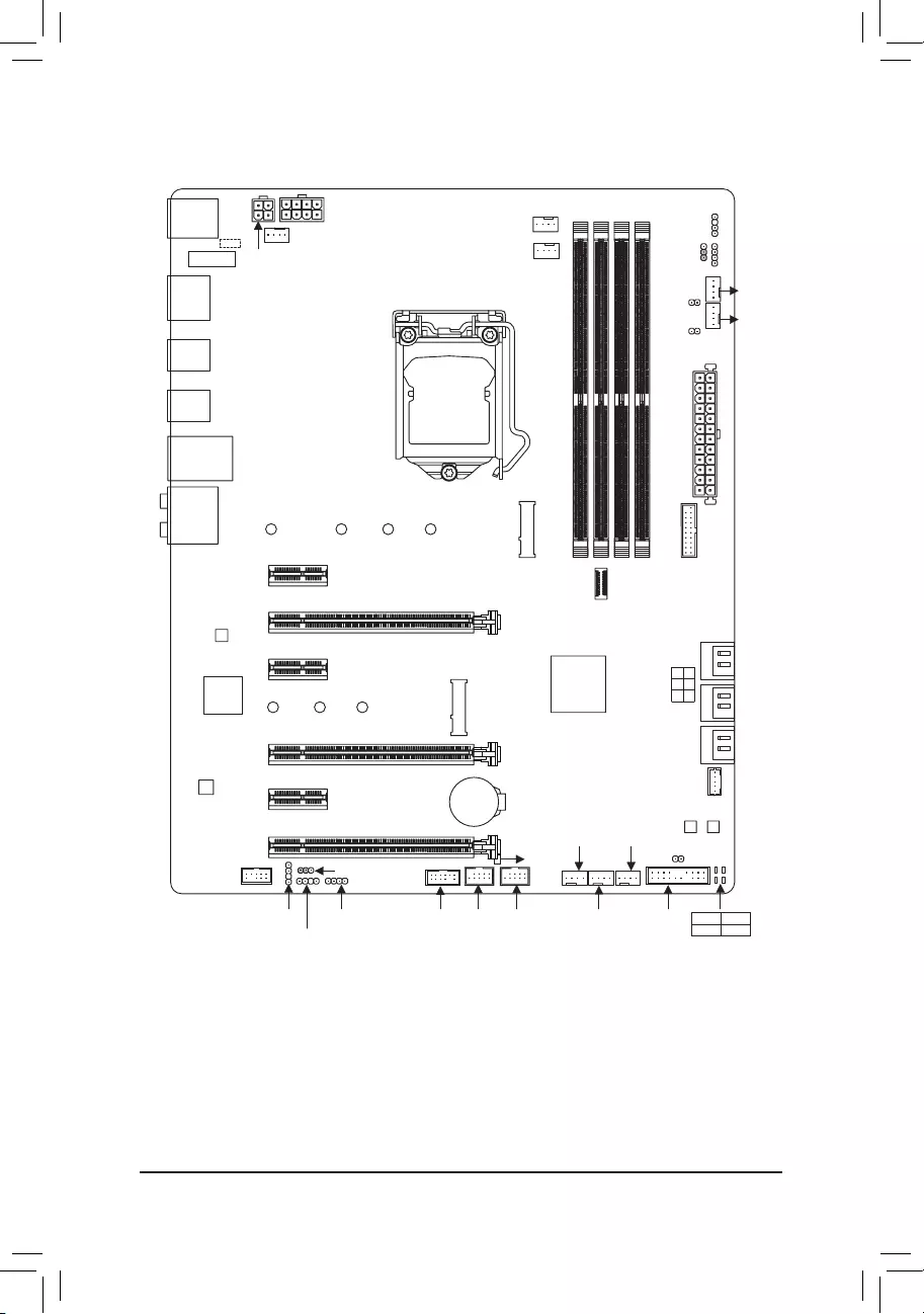
Z390 AORUS PRO (WIFI) Motherboard Layout
* The box contents above are for reference only and the actual items shall depend on the product package you obtain.
The box contents are subject to change without notice.
Box Contents
5Z390 AORUS PRO or Z390 AORUS PRO WIFI motherboard
5Motherboard driver disk 5One digital LED strip adapter cable
5User’s Manual 5One RGB LED strip extension cable
5Quick Installation Guide 5One Wi-Fi antenna (Note 1)
5Four SATA cables 5One G Connector
5M.2 screw(s)/M.2 standoff(s) 5Two thermistor cables
WIFI MODULE
(Note 1)
R_USB1
R_USB30
TYPEC
USB31
HDMI
USB30_LAN
LGA1151
ATX
AUDIO
DDR4_B1
DDR4_B2
DDR4_A1
DDR4_A2
ATX_12V_2X2
Intel® Z390
CLR_CMOS
THB_C
M_BIOS
B_BIOS
PCIEX1_1
PCIEX8
PCIEX4
PCIEX16
PCIEX1_2
PCIEX1_3
F_USB30
F_USB30C
SYS_FAN6_
PUMP
M2M
CODEC
Z390 AORUS PRO (WIFI)
F_PANELF_USB1F_USB2TPMLED_C1
DLED_V_SW1
SPDIF_O
F_AUDIO
SYS_FAN3
D_LED1
SYS_FAN1
CNVI
(Note 1)
CPU_FAN
LED_C2
D_LED2
DLED_V_SW2
CPU_OPT
iTE®
Super I/O 426080
M2A
426080110
SATA3 531
420
BAT
Intel® GbE
LAN
CPU DRAM
VGA BOOT
EC_TEMP2
EC_TEMP1
SYS_FAN5_
PUMP
ATX_12V_2X4
SYS_FAN4
USB 2.0
Hub (Note 2)
USB 2.0 Hub
SYS_FAN2

Chapter 1 Hardware Installation
1-1 Installation Precautions
The motherboard contains numerous delicate electronic circuits and components which can become
damaged as a result of electrostatic discharge (ESD). Prior to installation, carefully read the user’s
manual and follow these procedures:
•Prior to installation, make sure the chassis is suitable for the motherboard.
•Prior to installation, do not remove or break motherboard S/N (Serial Number) sticker or
warranty sticker provided by your dealer. These stickers are required for warranty validation.
•Always remove the AC power by unplugging the power cord from the power outlet before
installing or removing the motherboard or other hardware components.
•When connecting hardware components to the internal connectors on the motherboard, make
sure they are connected tightly and securely.
•When handling the motherboard, avoid touching any metal leads or connectors.
•It is best to wear an electrostatic discharge (ESD) wrist strap when handling electronic
components such as a motherboard, CPU or memory. If you do not have an ESD wrist strap,
keepyourhandsdryandrsttouchametalobjecttoeliminatestaticelectricity.
•Prior to installing the motherboard, please have it on top of an antistatic pad or within an
electrostatic shielding container.
•Before connecting or unplugging the power supply cable from the motherboard, make sure
the power supply has been turned off.
•Before turning on the power, make sure the power supply voltage has been set according to
the local voltage standard.
•Before using the product, please verify that all cables and power connectors of your hardware
components are connected.
•To prevent damage to the motherboard, do not allow screws to come in contact with the
motherboard circuit or its components.
•Make sure there are no leftover screws or metal components placed on the motherboard or
within the computer casing.
•Do not place the computer system on an uneven surface.
•Do not place the computer system in a high-temperature or wet environment.
•Turning on the computer power during the installation process can lead to damage to system
components as well as physical harm to the user.
•If you are uncertain about any installation steps or have a problem related to the use of the
product,pleaseconsultacertiedcomputertechnician.
•If you use an adapter, extension power cable, or power strip, ensure to consult with its installation
and/or grounding instructions.
— 6 —
1-2 ProductSpecications
CPU Support for Intel 9000 Processors and 8th Generation Intel® Core™ i7 processors/
Intel® Core™ i5 processors/Intel® Core™ i3 processors/Intel® Pentium® processors/
Intel® Celeron® processors in the LGA1151 package
(Go to GIGABYTE’s website for the latest CPU support list.)
L3 cache varies with CPU
Chipset Intel® Z390 Express Chipset
Memory 4 x DDR4 DIMM sockets supporting up to 64 GB of system memory
Dual channel memory architecture
Support for DDR4 2666/2400/2133 MHz memory modules
Support for ECC Un-buffered DIMM 1Rx8/2Rx8 memory modules (operate in
non-ECC mode)
Support for non-ECC Un-buffered DIMM 1Rx8/2Rx8/1Rx16 memory modules
Support for Extreme Memory Prole (XMP) memory modules
(Go to GIGABYTE’s website for the latest supported memory speeds and memory
modules.)
Onboard
Graphics
Integrated Graphics Processor-Intel® HD Graphics support:
— 1 x HDMI port, supporting a maximum resolution of 4096×2160@30 Hz
* Support for HDMI 1.4 version and HDCP 2.2.
Maximum shared memory of 1 GB
Audio Realtek® ALC1220-VB codec
* The back panel line out jack supports DSD audio.
HighDenitionAudio
2/4/5.1/7.1-channel
Support for S/PDIF Out
LAN Intel® GbE LAN chip (10/100/1000 Mbit)
Wireless
Communication
Module (Note)
Intel® CNVi interface 802.11a/b/g/n/ac, supporting 2.4/5 GHz Dual-Band
BLUETOOTH 5
Support for 11ac 160 MHz wireless standard and up to 1.73 Gbps data rate
* Actual data rate may vary depending on environment and equipment.
Expansion Slots 1 x PCI Express x16 slot, running at x16 (PCIEX16)
* For optimum performance, if only one PCI Express graphics card is to be installed,
be sure to install it in the PCIEX16 slot.
1 x PCI Express x16 slot, running at x8 (PCIEX8)
* The PCIEX8 slot shares bandwidth with the PCIEX16 slot. When the PCIEX8 slot is
populated, the PCIEX16 slot operates at up to x8 mode.
1 x PCI Express x16 slot, running at x4 (PCIEX4)
3 x PCI Express x1 slots
(All of the PCI Express slots conform to PCI Express 3.0 standard.)
1 x M.2 Socket 1 connector for an Intel® CNVi wireless module (CNVI) (Note)
Multi-Graphics
Technology
Support for NVIDIA® Quad-GPU SLI™ and 2-Way NVIDIA® SLI™ technologies
Support for AMD Quad-GPU CrossFire™ and 3-Way/2-Way AMD CrossFire™
technologies
(Note) Only for the Z390 AORUS PRO WIFI.
— 7 —
Storage Interface Chipset:
— 1 x M.2 connector (Socket 3, M key, type 2242/2260/2280/22110 SATA and
PCIe x4/x2 SSD support) (M2A)
— 1 x M.2 connector (Socket 3, M key, type 2242/2260/2280 SATA and PCIe
x4/x2 SSD support, prepared for Intel® Hybrid SSD) (M2M)
— 6 x SATA 6Gb/s connectors
— Support for RAID 0, RAID 1, RAID 5, and RAID 10
* Refer to «1-8 Internal Connectors,» for the installation notices for the M.2 and SATA
connectors.
Intel® Optane™ Memory Ready
USB Chipset:
— 1 x USB Type-C™ port with USB 3.1 Gen 2 support on the back panel
— 1 x USB Type-C™ port with USB 3.1 Gen 1 support, available through the
internal USB header
— 2 x USB 3.1 Gen 2 Type-A ports (red) on the back panel
— 5 x USB 3.1 Gen 1 ports (3 ports on the back panel, 2 ports available through
the internal USB header)
Chipset+USB 2.0 Hub:
— 8 x USB 2.0/1.1 ports (4 ports on the back panel, 4 ports available through
the internal USB headers)
Internal
Connectors
1 x 24-pin ATX main power connector
1 x 8-pin ATX 12V power connector
1 x 4-pin ATX 12V power connector
1 x CPU fan header
1 x water cooling CPU fan header
4 x system fan headers
2 x system fan/water cooling pump headers
2 x digital LED strip headers
2 x digital LED strip power select jumpers
2 x RGB LED strip headers
6 x SATA 6Gb/s connectors
2 x M.2 Socket 3 connectors
1 x front panel header
1 x front panel audio header
1 x S/PDIF Out header
1 x USB Type-C™ port, with USB 3.1 Gen 1 support
1 x USB 3.1 Gen 1 header
2 x USB 2.0/1.1 headers
1 x Thunderbolt™ add-in card connector
1 x Trusted Platform Module (TPM) header (2x6 pin, for the GC-TPM2.0_S
module only)
1 x Clear CMOS jumper
2 x temperature sensor headers
— 8 —
Back Panel
Connectors
4 x USB 2.0/1.1 ports
2 x SMA antenna connectors (2T2R) (Note)
1 x HDMI port
1 x USB Type-C™ port, with USB 3.1 Gen 2 support
2 x USB 3.1 Gen 2 Type-A ports (red)
3 x USB 3.1 Gen 1 ports
1 x RJ-45 port
1 x optical S/PDIF Out connector
5 x audio jacks
I/O Controller iTE® I/O Controller Chip
Hardware
Monitor
Voltage detection
Temperature detection
Fan speed detection
Water cooling ow rate detection
Overheating warning
Fan fail warning
Fan speed control
* Whether the fan (pump) speed control function is supported will depend on the fan
(pump) you install.
BIOS 2 x 128 Mbit ash
Use of licensed AMI UEFI BIOS
Support for DualBIOS™
PnP 1.0a, DMI 2.7, WfM 2.0, SM BIOS 2.7, ACPI 5.0
Unique Features Support for APP Center
* Available applications in APP Center may vary by motherboard model. Supported
functions of each application may also vary depending on motherboard specications.
— 3D OSD
— @BIOS
— AutoGreen
— Cloud Station
— EasyTune
— Easy RAID
— Fast Boot
— Game Boost
— ON/OFF Charge
— Platform Power Management
— RGB Fusion
(Note) Only for the Z390 AORUS PRO WIFI.
— 9 —
Unique Features — Smart Backup
— Smart Keyboard
— Smart TimeLock
— Smart HUD
— System Information Viewer
— Smart Survey
— USB Blocker
Support for Q-Flash
Support for Xpress Install
Bundled
Software
Norton® Internet Security (OEM version)
cFosSpeed
Operating
System Support for Windows 10 64-bit
Form Factor ATX Form Factor; 30.5cm x 24.4cm
* GIGABYTE reserves the right to make any changes to the product specications and product-related information without
prior notice.
Please visit GIGABYTE’s website for support lists of CPU, memory
modules, SSDs, and M.2 devices.
Please visit the SupportUtility List page on GIGABYTE’s website to download the latest
version of apps.
Z390 AORUS PRO Z390 AORUS PRO
WIFI
— 10 —
1-3 Installing the CPU
1-4 Installing the Memory
Read the following guidelines before you begin to install the memory:
•Make sure that the motherboard supports the memory. It is recommended that memory of the same
capacity, brand, speed, and chips be used.
(Go to GIGABYTE’s website for the latest supported memory speeds and memory modules.)
•Always turn off the computer and unplug the power cord from the power outlet before installing the
memory to prevent hardware damage.
•Memory modules have a foolproof design. A memory module can be installed in only one direction.
If you are unable to insert the memory, switch the direction.
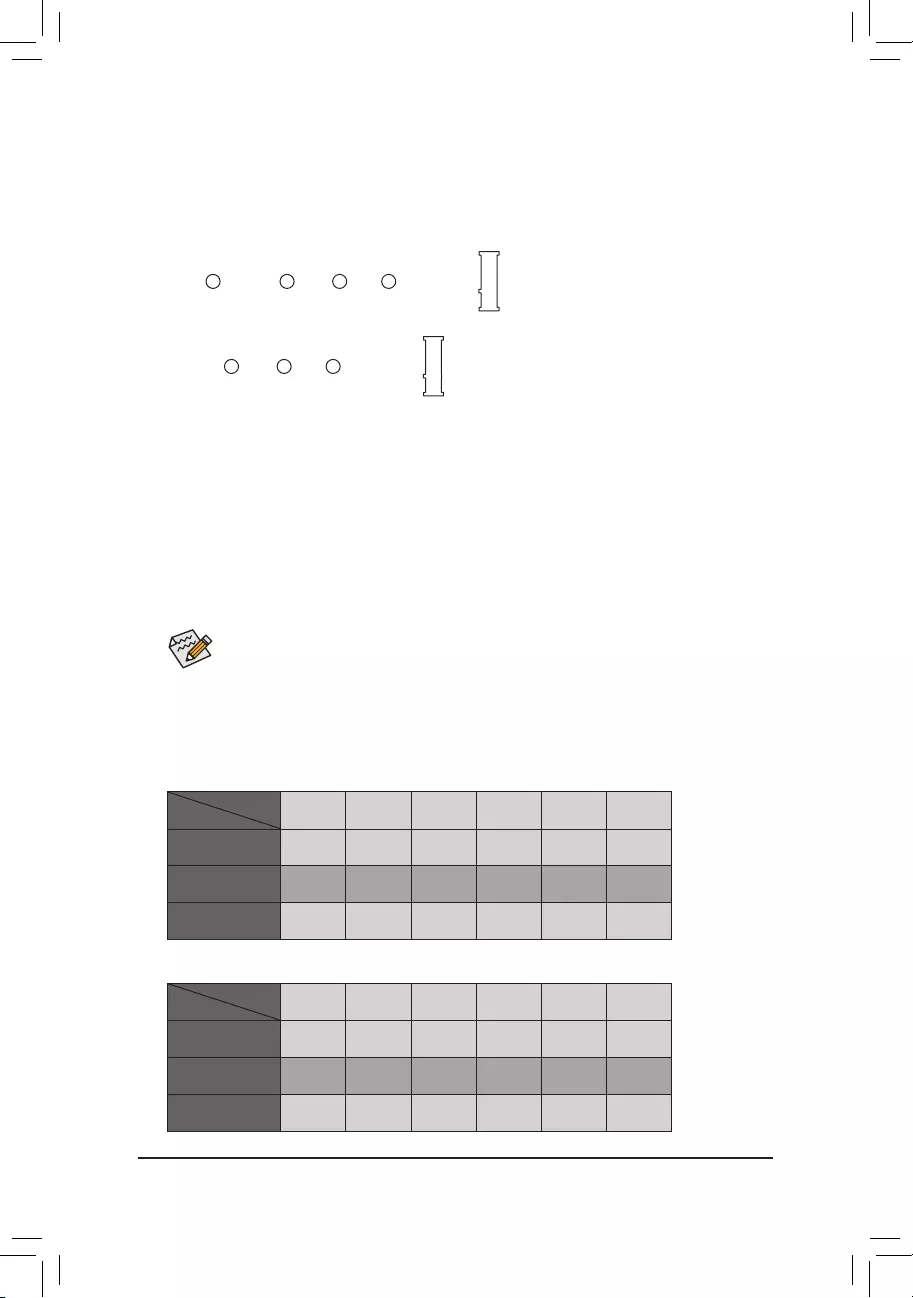
DualChannelMemoryConguration
This motherboard provides four memory sockets and supports Dual Channel Technology. After the memory
isinstalled,theBIOSwillautomaticallydetectthespecicationsandcapacityofthememory.EnablingDual
Channel memory mode will double the original memory bandwidth.
The four memory sockets are divided into two channels and each channel has two memory sockets as following:
Please visit GIGABYTE’s website for details on hardware installation.
Read the following guidelines before you begin to install the CPU:
•Make sure that the motherboard supports the CPU.
(Go to GIGABYTE’s website for the latest CPU support list.)
•Always turn off the computer and unplug the power cord from the power outlet before installing the
CPU to prevent hardware damage.
•Locate the pin one of the CPU. The CPU cannot be inserted if oriented incorrectly. (Or you may
locate the notches on both sides of the CPU and alignment keys on the CPU socket.)
•Apply an even and thin layer of thermal grease on the surface of the CPU.
•Do not turn on the computer if the CPU cooler is not installed, otherwise overheating and damage
of the CPU may occur.
•SettheCPUhostfrequencyinaccordancewiththeCPUspecications.Itisnotrecommended
thatthesystembusfrequencybesetbeyondhardwarespecicationssinceitdoesnotmeetthe
standard requirements for the peripherals. If you wish to set the frequency beyond the standard
specications,pleasedosoaccordingtoyourhardwarespecicationsincludingtheCPU,graphics
card, memory, hard drive, etc.
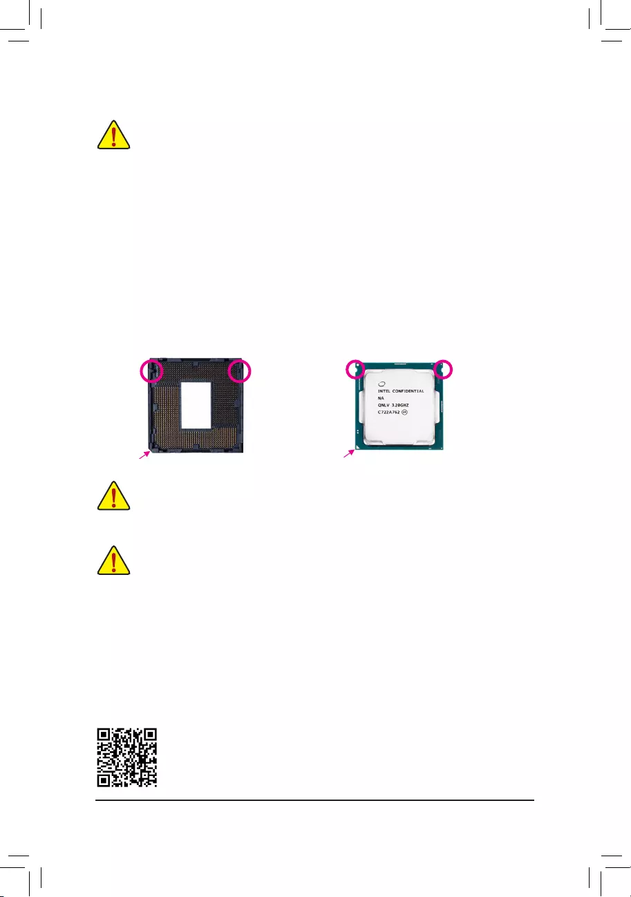
Installing the CPU
Locate the alignment keys on the motherboard CPU socket and the notches on the CPU.
Do not remove the CPU socket cover before inserting the CPU. It may pop off from the load
plate automatically during the process of re-engaging the lever after you insert the CPU.
Triangle Pin One Marking on the CPU
NotchNotch
LGA1151 CPU
Alignment KeyAlignment Key
LGA1151 CPU Socket
Pin One Corner of the CPU Socket
— 11 —
Channel A: DDR4_A1, DDR4_A2
Channel B: DDR4_B1, DDR4_B2
DualChannelMemoryCongurationsTable
DDR4_B1 DDR4_B2 DDR4_A1 DDR4_A2
2 Modules — — DS/SS — — DS/SS
DS/SS — — DS/SS — —
4 Modules DS/SS DS/SS DS/SS DS/SS
(SS=Single-Sided, DS=Double-Sided, «- -«=No Memory)
Due to CPU limitations, read the following guidelines before installing the memory in Dual Channel mode.
1. Dual Channel mode cannot be enabled if only one memory module is installed.
2. When enabling Dual Channel mode with two or four memory modules, it is recommended that memory
of the same capacity, brand, speed, and chips be used.
Procedure and driver screen for enabling CrossFire/SLI technology may differ by graphics cards and driver version.
Refer to the manual that came with your graphics cards for more information about enabling CrossFire/SLI technology.
1-5 Installing an Expansion Card
Read the following guidelines before you begin to install an expansion card:
•Make sure the motherboard supports the expansion card. Carefully read the manual that came
with your expansion card.
•Always turn off the computer and unplug the power cord from the power outlet before installing an
expansion card to prevent hardware damage.
B. Connecting the Graphics Cards
Step 1:
Observe the steps in «1-5 Installing an Expansion Card» and install CrossFire/SLI graphics cards on the PCI
Expressx16slots. (To setup a 2-Wayconguration,we recommendinstallingthe graphics cardson the
PCIEX16 and PCIEX8 slots.)
Step 2:
Insert the CrossFire (Note 2)/SLI bridge connectors in the CrossFire/SLI gold edge connectors on top of the cards.
Step 3:
Plug the display cable into the graphics card on the PCIEX16 slot.
1-6 Setting up AMD CrossFire™/NVIDIA® SLI™Conguration
A. System Requirements
—Windows 10 64-bit operating system
—A CrossFire/SLI-supported motherboard with two or more PCI Express x16 slots and correct driver
—CrossFire/SLI-ready graphics cards of identical brand and chip and correct driver
(For the latest GPUs that support the 3-way CrossFire technology, please refer to the AMD website.) (Note 1)
—CrossFire (Note 2)/SLI bridge connectors
—Apowersupplywithsufcientpowerisrecommended(Refertothemanualofyourgraphicscardsforthe
power requirement)
C.ConguringtheGraphicsCardDriver
C-1. To Enable CrossFire Function
After installing the graphics card driver in the operating system, go to the AMD RADEON SETTINGS screen.
Browse to GamingGlobal Settings and ensure AMD CrossFire is set to On.
C-2. To Enable SLI Function
After installing the graphics card driver in the operating system, go to the NVIDIA Control Panel. Browse to the
CongureSLI,Surround,Physx screen and ensure Maximize 3D performance is enabled.
(Note 1) When using dual core graphics cards, only 2-way is supported.
(Note 2) The bridge connector(s) may be needed or not depending on your graphics cards.
— 12 —
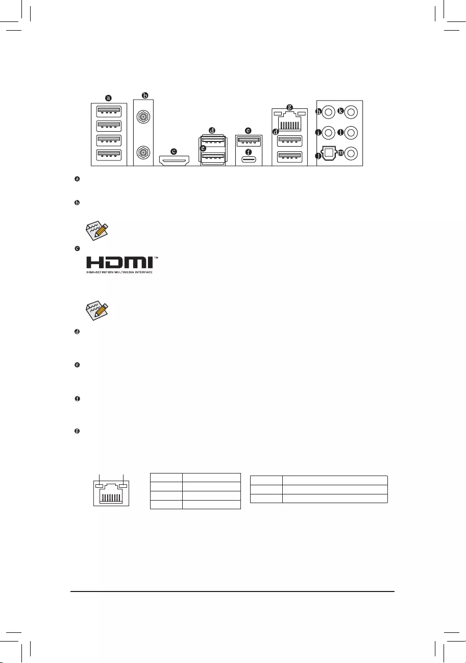
1-7 Back Panel Connectors
USB 2.0/1.1 Port
TheUSBportsupportstheUSB2.0/1.1specication.UsethisportforUSBdevices.
SMA Antenna Connectors (2T2R) (Note)
Use this connector to connect an antenna.
HDMI Port
The HDMI port supports HDCP 2.2 and Dolby TrueHD and DTS HD Master Audio
formats. It also supports up to 192KHz/16bit 8-channel LPCM audio output. You
can use this port to connect your HDMI-supported monitor. The maximum supported resolution is
4096×2160@30 Hz, but the actual resolutions supported are dependent on the monitor being used.
After installing the HDMI device, make sure to set the default sound playback device to HDMI.
(The item name may differ depending on your operating system.)
Tighten the antenna cables to the antenna connectors and then move the antenna to a place
where the signal is good.
USB 3.1 Gen 1 Port
TheUSB3.1Gen1portsupportstheUSB3.1Gen1specicationandiscompatibletotheUSB2.0
specication.UsethisportforUSBdevices.
USB 3.1 Gen 2 Type-A Port (Red)
TheUSB3.1Gen2Type-AportsupportstheUSB3.1Gen2specicationandiscompatibletotheUSB
3.1Gen1andUSB2.0specication.UsethisportforUSBdevices.
USB Type-C™ Port
ThereversibleUSBportsupportstheUSB3.1Gen2specicationandiscompatibletotheUSB3.1Gen
1andUSB2.0specication.UsethisportforUSBdevices.
RJ-45 LAN Port
The Gigabit Ethernet LAN port provides Internet connection at up to 1 Gbps data rate. The following
describes the states of the LAN port LEDs.
(Note) Only for the Z390 AORUS PRO WIFI.
(Note)
Activity LED
Connection/
Speed LED
LAN Port
Activity LED:
Connection/Speed LED:
State Description
Orange 1 Gbps data rate
Green 100 Mbps data rate
Off 10 Mbps data rate
State Description
Blinking Data transmission or receiving is occurring
On No data transmission or receiving is occurring
— 13 —
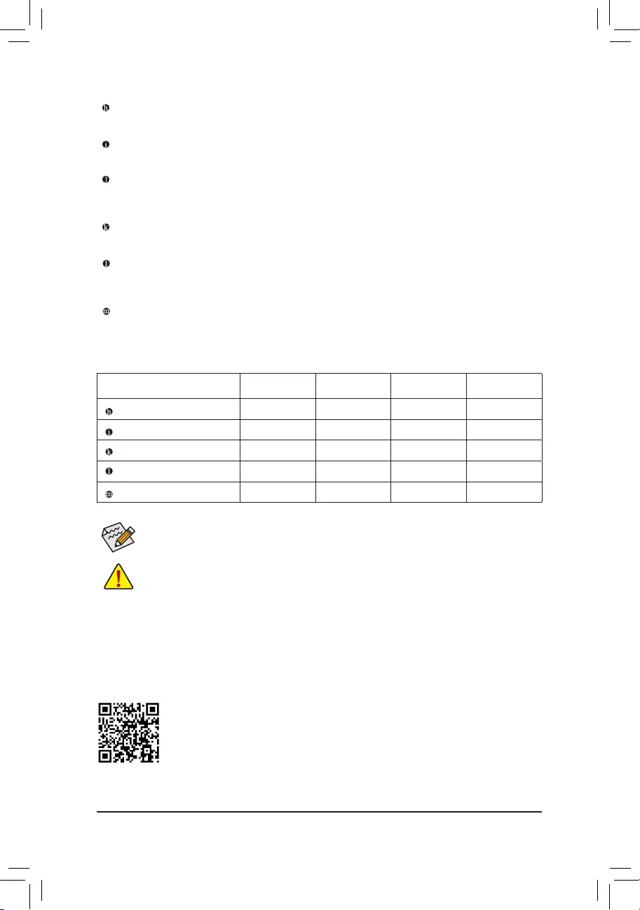
Center/Subwoofer Speaker Out
Use this audio jack to connect center/subwoofer speakers.
Rear Speaker Out
Use this audio jack to connect rear speakers.
Optical S/PDIF Out Connector
This connector provides digital audio out to an external audio system that supports digital optical audio.
Before using this feature, ensure that your audio system provides an optical digital audio in connector.
Line In/Side Speaker Out
The line in jack. Use this audio jack for line in devices such as an optical drive, walkman, etc.
Line Out/Front Speaker Out
The line out jack. This jack supports audio amplifying function. For better sound quality, it is recommended
that you connect your headphone/speaker to this jack (actual effects may vary by the device being used).
Mic In/Side Speaker Out
The Mic in jack.
AudioJackCongurations:
Jack Headphone/
2-channel 4-channel 5.1-channel 7.1-channel
Center/Subwoofer Speaker Out a a
Rear Speaker Out aaa
Line In/Side Speaker Out a
Line Out/Front Speaker Out a a a a
Mic In/Side Speaker Out a
•Whenremovingthecableconnectedtoabackpanelconnector,rstremovethecablefromyour
device and then remove it from the motherboard.
•When removing the cable, pull it straight out from the connector. Do not rock it side to side to
prevent an electrical short inside the cable connector.
If you want to install a Side Speaker, you need to retask either the Line in or Mic in jack to be Side
Speaker out through the audio driver.
PleasevisitGIGABYTE’swebsitefordetailsonconguringtheaudiosoftware.
— 14 —
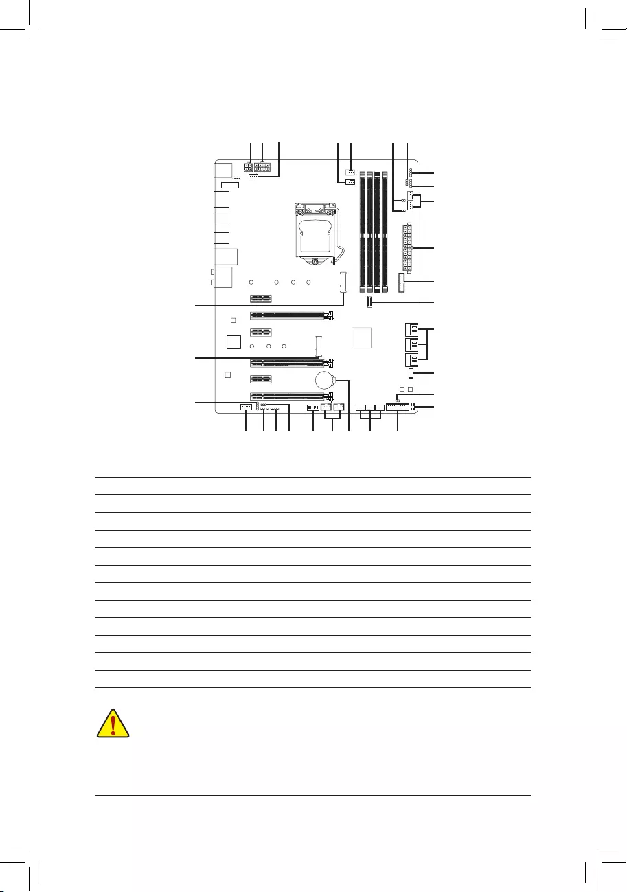
1-8 Internal Connectors
Read the following guidelines before connecting external devices:
•First make sure your devices are compliant with the connectors you wish to connect.
•Before installing the devices, be sure to turn off the devices and your computer. Unplug the power
cord from the power outlet to prevent damage to the devices.
•After installing the device and before turning on the computer, make sure the device cable has
been securely attached to the connector on the motherboard.
1) ATX_12V_2X2/ATX_12V_2X4
2) ATX
3) CPU_FAN
4) SYS_FAN1/2/3/4
5) SYS_FAN5/6_PUMP
6) CPU_OPT
7) EC_TEMP1/EC_TEMP2
 LED_C1/LED_C2
9) D_LED1/D_LED2
10) DLED_V_SW1/DLED_V_SW2
11) SATA3 0/1/2/3/4/5
12) M2A/M2M
13) F_PANEL
14) F_AUDIO
15) SPDIF_O
16) F_USB30C
17) F_USB30
18) F_USB1/F_USB2
19) TPM
20) THB_C
21) CLR_CMOS
22) BAT
23) CPU/DRAM/VGA/BOOT
5
8
9
13
2
11
16
1914 9 10
1
1
8
20
12
15
12
18 4
3 106 7
21
22
4
23
17
— 15 —
131
2412
ATX
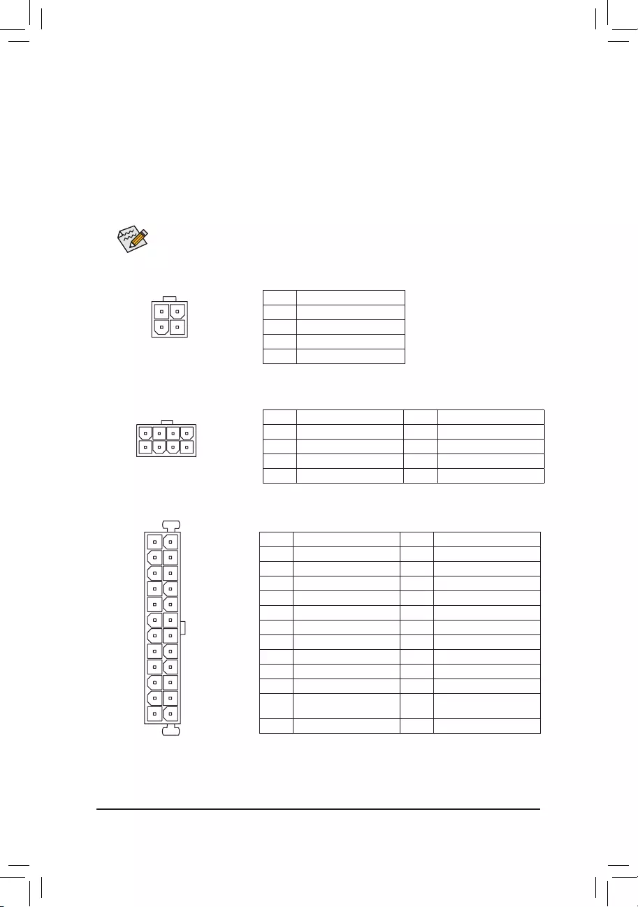
1/2)ATX_12V_2X2/ATX_12V_2X4/ATX(2×2,2×4,12VPowerConnectorsand2×12Main
Power Connector)
With the use of the power connector, the power supply can supply enough stable power to all the components
onthemotherboard.Beforeconnectingthepowerconnector,rstmakesurethepowersupplyisturned
off and all devices are properly installed. The power connector possesses a foolproof design. Connect the
power supply cable to the power connector in the correct orientation.
The 12V power connector mainly supplies power to the CPU. If the 12V power connector is not connected,
the computer will not start.
To meet expansion requirements, it is recommended that a power supply that can withstand high
power consumption be used (500W or greater). If a power supply is used that does not provide the
required power, the result can lead to an unstable or unbootable system.
ATX:
Pin No. Denition Pin No. Denition
1 3.3V 13 3.3V
2 3.3V 14 -12V
3 GND 15 GND
4 +5V 16 PS_ON (soft On/Off)
5 GND 17 GND
6 +5V 18 GND
7 GND 19 GND
8 Power Good 20 NC
9 5VSB (stand by +5V) 21 +5V
10 +12V 22 +5V
11 +12V (Only for 2×12-pin
ATX)
23 +5V (Only for 2×12-pin ATX)
12 3.3V (Only for 2×12-pin ATX) 24 GND (Only for 2×12-pin ATX)
ATX_12V_2X4:
Pin No. Denition Pin No. Denition
1 GND (Only for 2×4-pin 12V) 5 +12V (Only for 2×4-pin 12V)
2 GND (Only for 2×4-pin 12V) 6 +12V (Only for 2×4-pin 12V)
3 GND 7 +12V
4 GND 8 +12V
ATX_12V_2X4
41
85
ATX_12V_2X2:
Pin No. Denition
1 GND
2 GND
3 +12V
4 +12V
ATX_12V_2X2
2
4
1
3
— 16 —
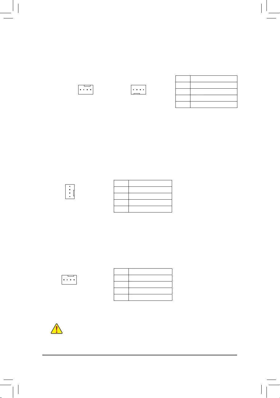
3/4) CPU_FAN/SYS_FAN1/2/3/4 (Fan Headers)
All fan headers on this motherboard are 4-pin. Most fan headers possess a foolproof insertion design.
When connecting a fan cable, be sure to connect it in the correct orientation (the black connector wire is
the ground wire). The speed control function requires the use of a fan with fan speed control design. For
optimum heat dissipation, it is recommended that a system fan be installed inside the chassis.
CPU_FAN/SYS_FAN1
1 1
SYS_FAN2/SYS_FAN3/SYS_FAN4
Pin No. Denition
1 GND
2 Voltage Speed Control
3 Sense
4 PWM Speed Control
5) SYS_FAN5/6_PUMP (System Fan/Water Cooling Pump Headers)
The fan/pump headers are 4-pin and possess a foolproof insertion design. Most fan headers possess a
foolproof insertion design. When connecting a fan cable, be sure to connect it in the correct orientation (the
black connector wire is the ground wire). The speed control function requires the use of a fan with fan speed
control design. For optimum heat dissipation, it is recommended that a system fan be installed inside the
chassis. The header also provides speed control for a water cooling pump, refer to Chapter 2, «BIOS Setup,»
«M.I.T.,» for more information.
Pin No. Denition
1 GND
2 Voltage Speed Control
3 Sense
4 PWM Speed Control
1
6) CPU_OPT (Water Cooling CPU Fan Header)
The fan header is 4-pin and possesses a foolproof insertion design. Most fan headers possess a foolproof
insertion design. When connecting a fan cable, be sure to connect it in the correct orientation (the black
connector wire is the ground wire). The speed control function requires the use of a fan with fan speed control
design.
1
Pin No. Denition
1 GND
2 Voltage Speed Control
3 Sense
4 PWM Speed Control
•Be sure to connect fan cables to the fan headers to prevent your CPU and system from
overheating. Overheating may result in damage to the CPU or the system may hang.
•Thesefanheadersarenotcongurationjumperblocks.Donotplaceajumpercapontheheaders.
— 17 —
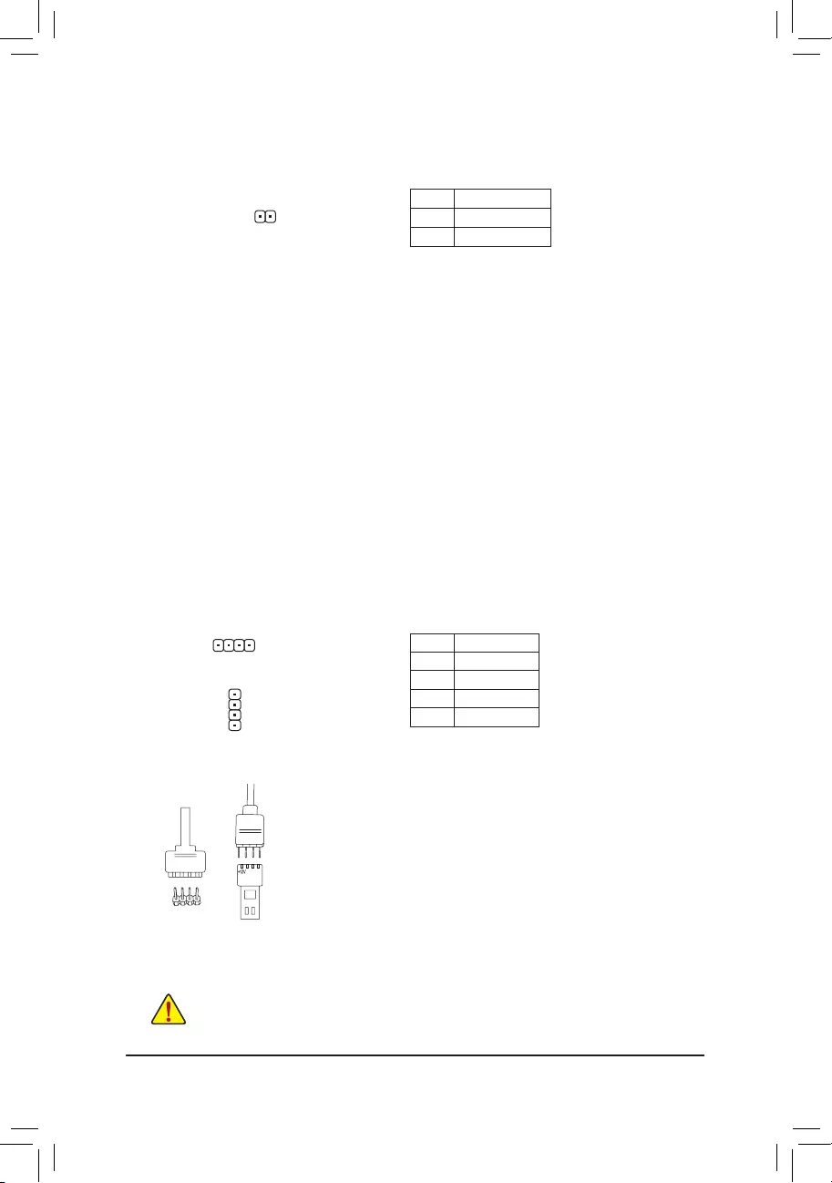
7) EC_TEMP1/EC_TEMP2 (Temperature Sensor Headers)
Connect the thermistor cables to the headers for temperature detection.
Pin No. Denition
1 SENSOR IN
2 GND
1
LED_C1/LED_C2 (RGB LED Strip Headers)
The headers can be used to connect a standard 5050 RGB LED strip (12V/G/R/B), with maximum power
rating of 2A (12V) and maximum length of 2m.
Pin No. Denition
1 12V
2 G
3 R
4 B
Before installing the devices, be sure to turn off the devices and your computer. Unplug the power
cord from the power outlet to prevent damage to the devices.
1
1
LED_C1
LED_C2
Connect one end of the RGB LED strip extension cable to the header
and the other end to your RGB LED strip. The black wire (marked
with a triangle on the plug) of the extension cable must be connected
to Pin 1 (12V) of this header. The 12V pin (marked with an arrow) on
the other end of the extension cable must be lined up with the 12V of
the LED strip. Be careful with the connection orientation of the LED
strip; incorrect connection may lead to the damage of the LED strip.
12V
1
RGB LED
Strip
12VRGB
BG12VR
— 18 —
11) SATA3 0/1/2/3/4/5 (SATA 6Gb/s Connectors)
The SATA connectors conform to SATA 6Gb/s standard and are compatible with SATA 3Gb/s and SATA
1.5Gb/s standard. Each SATA connector supports a single SATA device. The Intel® Chipset supports RAID 0,
RAID1,RAID5,andRAID10.RefertoChapter3,»ConguringaRAIDSet,»forinstructionsonconguring
a RAID array.
Pin No. Denition
1 GND
2 TXP
3 TXN
4 GND
5 RXN
6 RXP
7 GND
To enable hot-plugging for the SATA ports, refer to Chapter 2, «BIOS Setup,» «PeripheralsSATA
AndRSTConguration,»formoreinformation.
1
1
SATA3 5 3 1
4 2 0
7
7
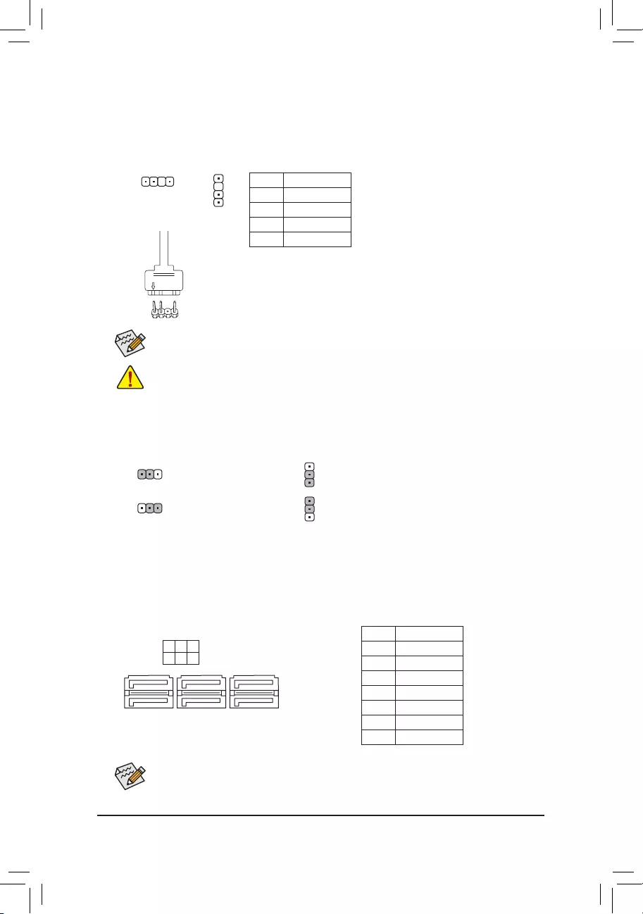
10) DLED_V_SW1/DLED_V_SW2 (Digital LED Strip Power Select Jumpers)
The jumpers allow you to select the supply voltage of the D_LED1 and D_LED2 headers. Be sure to
verify the voltage requirements of your digital LED strip and set the correct voltage with this jumper before
connection. Incorrect connection may lead to the damage of the LED strip.
1
1
1
1
1-2: 5V (Default) 1-2: 5V (Default)
2-3: 12V 2-3: 12V
DLED_V_SW1 DLED_V_SW2
9) D_LED1/D_LED2 (Digital LED Strip Headers)
The headers can be used to connect a standard 5050 digital LED strip, with maximum power rating of 5A
(12V or 5V) and maximum number of 1000 LEDs. There are 12V and 5V digital LED strips. Be sure to
verify the voltage requirements of your digital LED strip and set the DLED_V_SW1 and DLED_V_SW2
jumpers accordingly.
Pin No. Denition
1 V
2 D
3 No Pin
4 G
Before installing the devices, be sure to turn off the devices and your computer. Unplug the power
cord from the power outlet to prevent damage to the devices.
For how to turn on/off the lights of the LED strip please visit the «Unique Features» webpage
of GIGABYTE’s website.
D_LED1
D_LED2
Connect one end of the digital LED strip adapter cable to this header and
the other end to your digital LED strip. The power pin (marked with a triangle
on the plug) of the LED strip must be connected to Pin 1 of the digital LED
strip header. Incorrect connection may lead to the damage of the LED strip.
1
F_USB30 F_U
B_
F_ F_
_
B
BS_
B
SB_
B
_S
S_
_
B
_U
_
B
S
123
123
123
123
1
1
1
1
BSS
S
_S
SSU
1 2 3
S3 BSSS
U
__ 3
F_USB3F
S _
S _
S _
SF
B_
B_
F
_0
S
S
_0F
_F
_
_
__B
U
S _S
_ SF_
USB0_B
B_ F_USB3
F_USB303
_
_3U
F_USB30 F_U
B_
F_ F_
_
B
BS_
B
SB_
B
_S
S_
_
B
_U
_
B
S
123
123
123
123
1
1
1
1
BSS
S
_S
SSU
1 2 3
S3 BSSS
U
__ 3
F_USB3F
S _
S _
S _
SF
B_
B_
F
_0
S
S
_0F
_F
_
_
__B
U
S _S
_ SF_
USB0_B
B_ F_USB3
F_USB303
_
_3U
1
Digital LED strip
adapter cable
1
— 19 —
12) M2A/M2M (M.2 Socket 3 Connectors)
TheM.2connectorssupportM.2SATASSDsorM.2PCIeSSDsandsupportRAIDconguration.Please
note that an M.2 PCIe SSD cannot be used to create a RAID set either with an M.2 SATA SSD or a SATA
harddrive.TocreateaRAIDarraywithanM.2PCIeSSD,youmustsetupthecongurationinUEFIBIOS
mode.RefertoChapter3,»ConguringaRAIDSet,»forinstructionsonconguringaRAIDarray.
F_USB30 F_U
B_
F_ F_
_
B
BS_
B
SB_
B
_S
S_
_
B
_U
_
B
S
123
123
123
123
1
1
1
1
BSS
S
_S
SSU
1 2 3
S3 BSSS
U
__ 3
F_USB3F
S _
S _
S _
SF
B_
B_
F
_0
S
S
_0F
_F
_
_
__B
U
S _S
_ SF_
USB0_B
B_ F_USB3
F_USB303
_
_3U
80110 60 42
F_USB30 F_U
B_
F_ F_
_
B
BS_
B
SB_
B
_S
S_
_
B
_U
_
B
S
123
123
123
123
1
1
1
1
BSS
S
_S
SSU
1 2 3
S3 BSSS
U
__ 3
F_USB3F
S _
S _
S _
SF
B_
B_
F
_0
S
S
_0F
_F
_
_
__B
U
S _S
_ SF_
USB0_B
B_ F_USB3
F_USB303
_
_3U
80 60 42
Installation Notices for the M.2 and SATA Connectors:
Due to the limited number of lanes provided by the Chipset, the availability of the SATA connectors may
be affected by the type of device installed in the M.2 connectors. The M2A connector shares bandwidth
with the SATA3 1 connector; the M2M connector shares bandwidth with the SATA3 4, 5 connectors.Refer
to the following table for details.
Follow the steps below to correctly install an M.2 SSD in the M.2 connector.
Step 1:
Get a screw and a standoff from the included M.2 screw and standoff packs. Locate the M.2 connector
where you will install the M.2 SSD, use a screwdriver to unfasten the screw on the heatsink and then
remove the heatsink.
Step 2:
LocatethepropermountingholefortheM.2SSDtobeinstalledandthentightenthestandoffrst.Insert
the M.2 SSD into the M.2 connector at an angle.
Step 3:
Press the M.2 SSD down and then secure it with the screw. Replace the heatsink and secure it to the
original hole.
Select the proper hole for the M.2 SSD to be installed and refasten the screw and nut.
M2A
M2M
•M2M:
SATA3 0 SATA3 1 SATA3 2 SATA3 3 SATA3 4 SATA3 5
M.2 SATA SSD a a a a r r
M.2 PCIe SSD
a a a a r r
No M.2 SSD Installed a a a a a a
a: Available, r: Not available
Connector
Type of
M.2 SSD
•M2A:
SATA3 0 SATA3 1 SATA3 2 SATA3 3 SATA3 4 SATA3 5
M.2 SATA SSD ara a a a
M.2 PCIe SSD
a a a a a a
No M.2 SSD Installed a a a a a a
a: Available, r: Not available
Connector
Type of
M.2 SSD
— 20 —
The front panel design may differ by chassis. A front panel module mainly consists of power switch,
reset switch, power LED, hard drive activity LED, speaker and etc. When connecting your chassis
front panel module to this header, make sure the wire assignments and the pin assignments are
matched correctly.
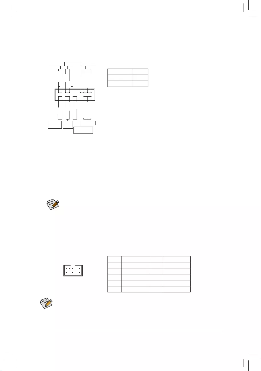
13) F_PANEL (Front Panel Header)
Connect the power switch, reset switch, speaker, chassis intrusion switch/sensor and system status indicator
on the chassis to this header according to the pin assignments below. Note the positive and negative pins
before connecting the cables.
System Status LED
S0 On
S3/S4/S5 Off
•PW (Power Switch, Red):
Connects to the power switch on the chassis front panel. You may
congurethewaytoturnoffyoursystemusingthepowerswitch(refer
to Chapter 2, «BIOS Setup,» «Power,» for more information).
•SPEAK (Speaker, Orange):
Connects to the speaker on the chassis front panel. The system reports
system startup status by issuing a beep code. One single short beep
will be heard if no problem is detected at system startup.
•PLED/PWR_LED (Power LED, Yellow/Purple):
Connects to the power status indicator
on the chassis front panel. The LED is on
when the system is operating. The LED is
off when the system is in S3/S4 sleep state
or powered off (S5).
•HD (Hard Drive Activity LED, Blue):
Connects to the hard drive activity LED on the chassis front panel. The LED is on when the hard drive
is reading or writing data.
•RES (Reset Switch, Green):
Connects to the reset switch on the chassis front panel. Press the reset switch to restart the computer
if the computer freezes and fails to perform a normal restart.
•CI (Chassis Intrusion Header, Gray):
Connects to the chassis intrusion switch/sensor on the chassis that can detect if the chassis cover has
been removed. This function requires a chassis with a chassis intrusion switch/sensor.
•NC (Orange): No Connection.
14) F_AUDIO (Front Panel Audio Header)
ThefrontpanelaudioheadersupportsHighDenitionaudio(HD).Youmayconnectyourchassisfront
panel audio module to this header. Make sure the wire assignments of the module connector match the
pin assignments of the motherboard header. Incorrect connection between the module connector and the
motherboard header will make the device unable to work or even damage it.
Some chassis provide a front panel audio module that has separated connectors on each wire instead
of a single plug. For information about connecting the front panel audio module that has different wire
assignments, please contact the chassis manufacturer.
F_USB30 F_U
B_
F_ F_
_
B
BS_
B
SB_
B
_S
S_
_
B
_U
_
B
S
123
123
123
123
1
1
1
1
BSS
S
_S
SSU
1 2 3
S3 BSSS
U
__ 3
F_USB3F
S _
S _
S _
SF
B_
B_
F
_0
S
S
_0F
_F
_
_
__B
U
S _S
_ SF_
USB0_B
B_ F_USB3
F_USB303
_
_3U
9 1
10 2
Pin No. Denition Pin No. Denition
1 MIC2_L 6 Sense
2 GND 7 FAUDIO_JD
3 MIC2_R 8 No Pin
4 NC 9 LINE2_L
5 LINE2_R 10 Sense
NC
NC
Power LED
1
2
19
20
CI-
CI+
PWR_LED-
PWR_LED+
PLED-
PW-
SPEAK+
SPEAK-
PLED+
PW+
Power LED
HD-
RES+
HD+
RES-
Hard Drive
Activity LED
Reset
Switch Chassis Intrusion
Header
Power Switch Speaker
PWR_LED-
— 21 —
F_USB30 F_U
B_
F_ F_
_
B
BS_
B
SB_
B
_S
S_
_
B
_U
_
B
S
123
123
123
123
1
1
1
1
BSS
S
_S
SSU
1 2 3
S3 BSSS
U
__ 3
F_USB3F
S _
S _
S _
SF
B_
B_
F
_0
S
S
_0F
_F
_
_
__B
U
S _S
_ SF_
USB0_B
B_ F_USB3
F_USB303
_
_3U
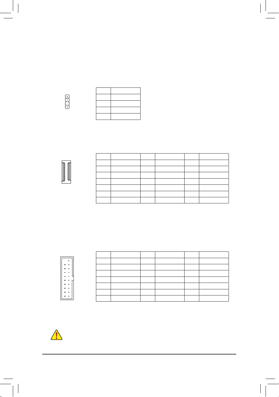
15) SPDIF_O (S/PDIF Out Header)
This header supports digital S/PDIF Out and connects a S/PDIF digital audio cable (provided by expansion
cards) for digital audio output from your motherboard to certain expansion cards like graphics cards and
sound cards. For example, some graphics cards may require you to use a S/PDIF digital audio cable for
digital audio output from your motherboard to your graphics card if you wish to connect an HDMI display
to the graphics card and have digital audio output from the HDMI display at the same time. For information
about connecting the S/PDIF digital audio cable, carefully read the manual for your expansion card.
Pin No. Denition
1 5VDUAL
2 No Pin
3 SPDIFO
4 GND
1
16) F_USB30C (USB Type-C™ Header with USB 3.1 Gen 1 Support)
TheheaderconformstoUSB3.1Gen1specicationandcanprovideoneUSBport.
Pin No. Denition Pin No. Denition Pin No. Denition
1 VBUS 8 CC1 15 RX2+
2 TX1+ 9 SBU1 16 RX2-
3 TX1- 10 SBU2 17 GND
4 GND 11 VBUS 18 D-
5 RX1+ 12 TX2+ 19 D+
6 RX1- 13 TX2- 20 CC2
7 VBUS 14 GND
Pin No. Denition Pin No. Denition Pin No. Denition
1 VBUS 8 D1- 15 SSTX2-
2 SSRX1- 9 D1+ 16 GND
3 SSRX1+ 10 NC 17 SSRX2+
4 GND 11 D2+ 18 SSRX2-
5 SSTX1- 12 D2- 19 VBUS
6 SSTX1+ 13 GND 20 No Pin
7 GND 14 SSTX2+
17) F_USB30 (USB 3.1 Gen 1 Header)
TheheaderconformstoUSB3.1Gen1andUSB2.0specicationandcanprovidetwoUSBports.For
purchasing the optional 3.5″ front panel that provides two USB 3.1 Gen 1 ports, please contact the local
dealer.
F_USB30 F_U
B_
F_ F_
_
B
BS_
B
SB_
B
_S
S_
_
B
_U
_
B
S
123
123
123
123
1
1
1
1
BSS
S
_S
SSU
1 2 3
S3 BSSS
U
__ 3
F_USB3F
S _
S _
S _
SF
B_
B_
F
_0
S
S
_0F
_F
_
_
__B
U
S _S
_ SF_
USB0_B
B_ F_USB3
F_USB303
_
_3U
10
20
20
10
1
11
11
1
Prior to installing the USB bracket, be sure to turn off your computer and unplug the power cord
from the power outlet to prevent damage to the USB bracket.
F_USB30 F_U
B_
F_ F_
_
B
BS_
B
SB_
B
_S
S_
_
B
_U
_
B
S
123
123
123
123
1
1
1
1
BSS
S
_S
SSU
1 2 3
S3 BSSS
U
__ 3
F_USB3F
S _
S _
S _
SF
B_
B_
F
_0
S
S
_0F
_F
_
_
__B
U
S _S
_ SF_
USB0_B
B_ F_USB3
F_USB303
_
_3U
— 22 —
19) TPM (Trusted Platform Module Header)
You may connect a TPM (Trusted Platform Module) to this header.
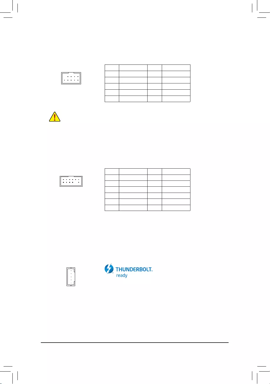
18) F_USB1/F_USB2 (USB 2.0/1.1 Headers)
TheheadersconformtoUSB2.0/1.1specication.EachUSBheadercanprovidetwoUSBportsviaan
optional USB bracket. For purchasing the optional USB bracket, please contact the local dealer.
Pin No. Denition Pin No. Denition
1 Power (5V) 6 USB DY+
2 Power (5V) 7 GND
3 USB DX- 8 GND
4 USB DY— 9 No Pin
5 USB DX+ 10 NC
•Do not plug the IEEE 1394 bracket (2×5-pin) cable into the USB 2.0/1.1 header.
•Prior to installing the USB bracket, be sure to turn off your computer and unplug the power cord
from the power outlet to prevent damage to the USB bracket.
10
9
2
1
Pin No. Denition Pin No. Denition
1LAD0 7LAD3
2VCC3 8GND
3LAD1 9LFRAME
4No Pin 10 NC
5LAD2 11 SERIRQ
6LCLK 12 LRESET
F_USB30 F_U
B_
F_ F_
_
B
BS_
B
SB_
B
_S
S_
_
B
_U
_
B
S
123
123
123
123
1
1
1
1
BSS
S
_S
SSU
1 2 3
S3 BSSS
U
__ 3
F_USB3F
S _
S _
S _
SF
B_
B_
F
_0
S
S
_0F
_F
_
_
__B
U
S _S
_ SF_
USB0_B
B_ F_USB3
F_USB303
_
_3U
12
11
2
1
20) THB_C (Thunderbolt™ Add-in Card Connector)
This connector is for a GIGABYTE Thunderbolt™ add-in card.
Supports a Thunderbolt™ add-in card.
F_USB30 F_U
B_
F_ F_
_
B
BS_
B
SB_
B
_S
S_
_
B
_U
_
B
S
123
123
123
123
1
1
1
1
BSS
S
_S
SSU
1 2 3
S3 BSSS
U
__ 3
F_USB3F
S _
S _
S _
SF
B_
B_
F
_0
S
S
_0F
_F
_
_
__B
U
S _S
_ SF_
USB0_B
B_ F_USB3
F_USB303
_
_3U
1
— 23 —
22) BAT (Battery)
Thebatteryprovidespowertokeepthevalues(suchasBIOScongurations,date,andtimeinformation)
in the CMOS when the computer is turned off. Replace the battery when the battery voltage drops to a low
level, or the CMOS values may not be accurate or may be lost.
23) CPU/DRAM/VGA/BOOT (Status LEDs)
The status LEDs show whether the CPU, memory, graphics card, and operating system are working
properly after system power-on. If the CPU/DRAM/VGA LED is on, that means the corresponding device
is not working normally; if the BOOT LED is on, that means you haven’t entered the operating system yet.
You may clear the CMOS values by removing the battery:
1. Turn off your computer and unplug the power cord.
2. Gently remove the battery from the battery holder and wait for one minute. (Or use a metal
object like a screwdriver to touch the positive and negative terminals of the battery holder,
making them short for 5 seconds.)
3. Replace the battery.
4. Plug in the power cord and restart your computer.
•Always turn off your computer and unplug the power cord before replacing the battery.
•Replace the battery with an equivalent one. Damage to your devices may occur if the battery is
replaced with an incorrect model.
•Contact the place of purchase or local dealer if you are not able to replace the battery by yourself
or uncertain about the battery model.
•When installing the battery, note the orientation of the positive side (+) and the negative side (-)
of the battery (the positive side should face up).
•Used batteries must be handled in accordance with local environmental regulations.
CPU: CPU status LED
DRAM: Memory status LED
VGA: Graphics card status LED
BOOT: Operating system status LED
F_USB30 F_U
B_
F_ F_
_
B
BS_
B
SB_
B
_S
S_
_
B
_U
_
B
S
123
123
123
123
1
1
1
1
BSS
S
_S
SSU
1 2 3
S3 BSSS
U
__ 3
F_USB3F
S _
S _
S _
SF
B_
B_
F
_0
S
S
_0F
_F
_
_
__B
U
S _S
_ SF_
USB0_B
B_ F_USB3
F_USB303
_
_3U
21) CLR_CMOS (Clear CMOS Jumper)
UsethisjumpertocleartheBIOScongurationandresettheCMOSvaluestofactorydefaults.Toclear
the CMOS values, use a metal object like a screwdriver to touch the two pins for a few seconds.
•Always turn off your computer and unplug the power cord from the power outlet before clearing
the CMOS values.
•After system restart, go to BIOS Setup to load factory defaults (select Load Optimized Defaults) or
manuallyconguretheBIOSsettings(refertoChapter2,«BIOSSetup,»forBIOScongurations).
Open: Normal
Short: Clear CMOS Values
— 24 —
CPU DRAM
VGA BOOT
BIOS (Basic Input and Output System) records hardware parameters of the system in the CMOS on the
motherboard. Its major functions include conducting the Power-On Self-Test (POST) during system startup,
saving system parameters and loading operating system, etc. BIOS includes a BIOS Setup program that allows
theusertomodifybasicsystemcongurationsettingsortoactivatecertainsystemfeatures.
When the power is turned off, the battery on the motherboard supplies the necessary power to the CMOS to
keepthecongurationvaluesintheCMOS.
To access the BIOS Setup program, press the <Delete> key during the POST when the power is turned on.
To upgrade the BIOS, use either the GIGABYTE Q-Flash or @BIOS utility.
•Q-Flash allows the user to quickly and easily upgrade or back up BIOS without entering the operating system.
•@BIOS is a Windows-based utility that searches and downloads the latest version of BIOS from the Internet
and updates the BIOS.
Chapter 2 BIOS Setup
•BecauseBIOSashingispotentiallyrisky,ifyoudonotencounterproblemsusingthecurrentversionofBIOS,
itisrecommendedthatyounotashtheBIOS.ToashtheBIOS,doitwithcaution.InadequateBIOSashing
may result in system malfunction.
•It is recommended that you not alter the default settings (unless you need to) to prevent system instability or other
unexpected results. Inadequately altering the settings may result in system’s failure to boot. If this occurs, try to
clear the CMOS values and reset the board to default values. (Refer to the «Load Optimized Defaults» section in
this chapter or introductions of the battery/clear CMOS jumper in Chapter 1 for how to clear the CMOS values.)
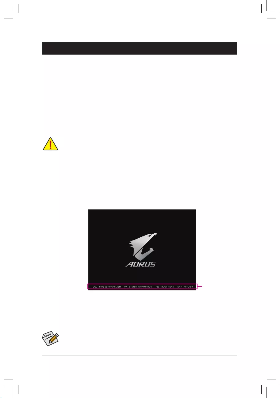
2-1 Startup Screen
The following startup Logo screen will appear when the computer boots.
(BIOS Sample: Z390 AORUS PRO WIFI, T0m)
Function Keys
•When the system is not stable as usual, select the Load Optimized Defaults item to set your system to its defaults.
•The BIOS Setup menus described in this chapter are for reference only and may differ by BIOS version.
There are two different BIOS modes as follows and you can use the <F2> key to switch between the two modes.
The Classic Setup mode provides detailed BIOS settings. You can press the arrow keys on your keyboard to move
among the items and press <Enter> to accept or enter a sub-menu. Or you can use your mouse to select the
item you want. Easy Mode allows users to quickly view their current system information or to make adjustments
foroptimumperformance.InEasyMode,youcanuseyourmousetomovethroughcongurationitems.
— 25 —
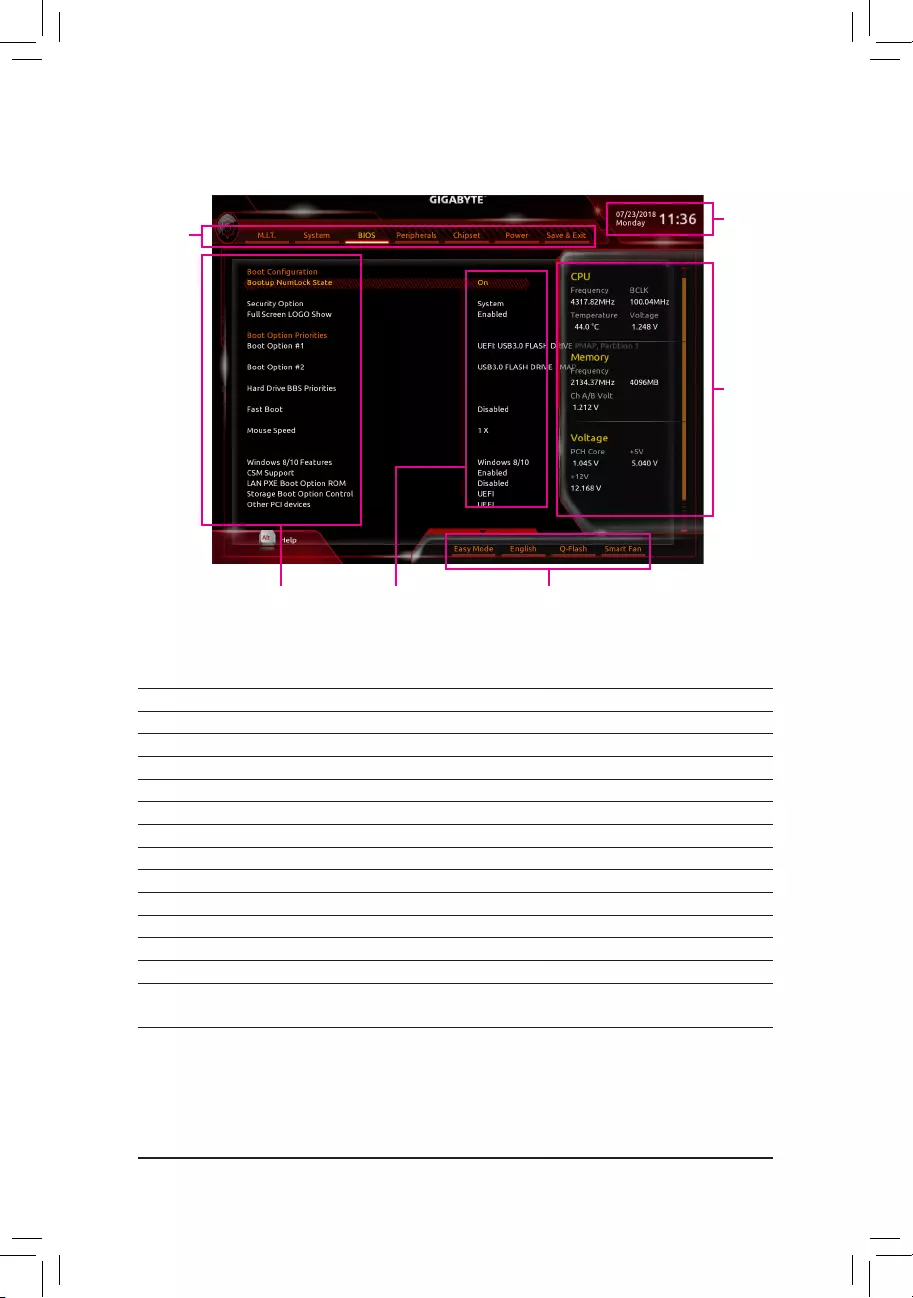
2-2 The Main Menu
Classic Setup Function Keys
<f><g> Move the selection bar to select a setup menu
<h><i>Movetheselectionbartoselectancongurationitemonamenu
<Enter> Execute command or enter a menu
<+>/<Page Up> Increase the numeric value or make changes
<—>/<Page Down> Decrease the numeric value or make changes
<F1> Show descriptions of the function keys
<F2> Switch to Easy Mode
<F5> Restore the previous BIOS settings for the current submenus
<F7> Load the Optimized BIOS default settings for the current submenus
<F8> Access the Q-Flash utility
<F9> Display system information
<F10> Save all the changes and exit the BIOS Setup program
<F12> Capture the current screen as an image and save it to your USB drive
<Esc> Main Menu: Exit the BIOS Setup program
Submenus: Exit current submenu
Hardware Infor—
mation
CongurationItems Current Settings
Setup Menus
System Time
Quick Access Bar allows you to enter Easy Mode, select
BIOSdefaultlanguage,congurefansettings,orenter
Q-Flash.
— 26 —
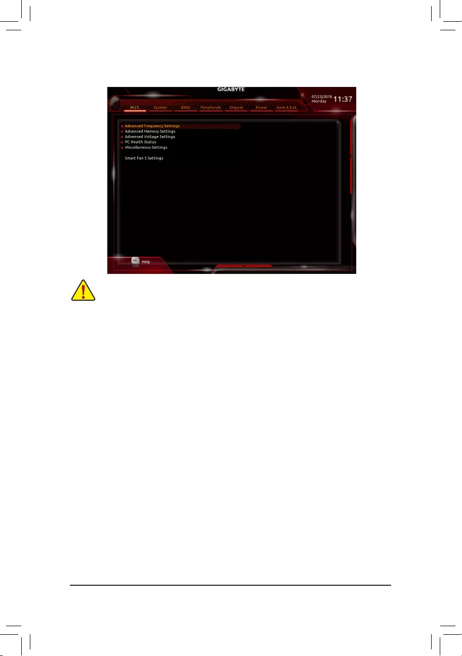
2-3 M.I.T.
Whether the system will work stably with the overclock/overvoltage settings you made is dependent on your overall
systemcongurations.Incorrectlydoingoverclock/overvoltagemayresultindamagetoCPU,chipset,ormemory
and reduce the useful life of these components. This page is for advanced users only and we recommend you not to
alter the default settings to prevent system instability or other unexpected results. (Inadequately altering the settings
may result in system’s failure to boot. If this occurs, clear the CMOS values and reset the board to default values.)
`Advanced Frequency Settings
&CPU Base Clock
Allows you to manually set the CPU base clock in 0.01 MHz increments. (Default: Auto)
Important: It is highly recommended that the CPU frequency be set in accordance with the CPU
specications.
&Host Clock Value
This value changes with the CPU Base Clock setting.
&Graphics Slice Ratio (Note)
Allows you to set the Graphics Slice Ratio.
&Graphics UnSlice Ratio (Note)
Allows you to set the Graphics UnSlice Ratio.
&CPU Upgrade (Note)
Allows you to set the CPU frequency. Options may vary depending on the CPU being used. (Default: Auto)
&Enhanced Multi-Core Performance
DetermineswhethertoallowtheCPUtorunatTurboC1speed.AutoletstheBIOSautomaticallycongure
this setting. (Default: Auto)
&CPU Clock Ratio
Allows you to alter the clock ratio for the installed CPU. The adjustable range is dependent on the CPU
being installed.
&CPU Frequency
Displays the current operating CPU frequency.
&FCLK Frequency for Early Power On
Allows you to set the FCLK frequency. Options are: Normal(800Mhz), 1GHz, 400MHz. (Default: 1GHz)
(Note) This item is present only when you install a CPU that supports this feature. For more information about
Intel® CPUs’ unique features, please visit Intel’s website.
— 27 —

`Advanced CPU Core Settings
&CPUClockRatio,CPUFrequency,FCLKFrequencyforEarlyPowerOn
The settings above are synchronous to those under the same items on the Advanced Frequency Settings
menu.
&AVX Offset (Note)
AVX offset is the negative offset of AVX ratio.
&Uncore Ratio
Allows you to set the CPU Uncore ratio. The adjustable range is dependent on the CPU being used.
&Uncore Frequency
Displays the current CPU Uncore frequency.
&CPU Flex Ratio Override
Enables or disables the CPU Flex Ratio. The maximum CPU clock ratio will be based on the CPU Flex
Ratio Settings value if CPU Clock Ratio is set to Auto. (Default: Disabled)
&CPU Flex Ratio Settings
Allows you to set the CPU Flex Ratio. The adjustable range may vary by CPU.
&Intel(R) Turbo Boost Technology (Note)
Allows you to determine whether to enable the Intel® CPU Turbo Boost technology. Auto lets the BIOS
automaticallycongurethissetting.(Default:Auto)
&Turbo Ratio (Note)
Allows you to set the CPU Turbo ratios for different number of active cores. Auto sets the CPU Turbo ratios
accordingtotheCPUspecications.(Default:Auto)
&Power Limit TDP (Watts) / Power Limit Time
AllowsyoutosetthepowerlimitforCPUTurbomodeandhowlongittakestooperateatthespecied
powerlimit.Ifthespeciedvalueisexceeded,theCPUwillautomaticallyreducethecorefrequencyin
order to reduce the power. AutosetsthepowerlimitaccordingtotheCPUspecications.(Default:Auto)
&Core Current Limit (Amps)
AllowsyoutosetacurrentlimitforCPUTurbomode.WhentheCPUcurrentexceedsthespeciedcurrent
limit, the CPU will automatically reduce the core frequency in order to reduce the current. Auto sets the
powerlimitaccordingtotheCPUspecications.(Default:Auto)
&Turbo Per Core Limit Control (Note)
Allows you to control each CPU core limit separately. (Default: Auto)
&No. of CPU Cores Enabled (Note)
Allows you to select the number of CPU cores to enable in an Intel® multi-core CPU (the number of CPU
cores may vary by CPU). AutoletstheBIOSautomaticallycongurethissetting.(Default:Auto)
&Hyper-Threading Technology (Note)
Allows you to determine whether to enable multi-threading technology when using an Intel® CPU that
supports this function. This feature only works for operating systems that support multi-processor mode.
AutoletstheBIOSautomaticallycongurethissetting.(Default:Auto)
&Intel(R) Speed Shift Technology (Intel® Speed Shift Technology) (Note)
Enables or disables Intel® Speed Shift Technology. Enabling this feature allows the processor to ramp up
its operating frequency more quickly and then improves the system responsiveness. (Default: Auto)
(Note) This item is present only when you install a CPU that supports this feature. For more information about
Intel® CPUs’ unique features, please visit Intel’s website.
— 28 —

&CPU Enhanced Halt (C1E) (Note)
Enables or disables Intel
®
CPU Enhanced Halt (C1E) function, a CPU power-saving function in system halt
state.
When enabled, the CPU core frequency and voltage will be reduced during system halt state to
decrease power consumption. AutoletstheBIOSautomaticallycongurethissetting.(Default:Auto)
&C3 State Support (Note)
Allows you to determine whether to let the CPU enter C3 mode in system halt state. When enabled, the
CPU core frequency and voltage will be reduced during system halt state to decrease power consumption.
The C3 state is a more enhanced power-saving state than C1. AutoletstheBIOSautomaticallycongure
this setting. (Default: Auto)
&C6/C7 State Support (Note)
Allows you to determine whether to let the CPU enter C6/C7 mode in system halt state. When enabled, the
CPU core frequency and voltage will be reduced during system halt state to decrease power consumption.
The C6/C7 state is a more enhanced power-saving state than C3. AutoletstheBIOSautomaticallycongure
this setting. (Default: Auto)
&C8 State Support (Note)
Allows you to determine whether to let the CPU enter C8 mode in system halt state. When enabled, the CPU
core frequency and voltage will be reduced during system halt state to decrease power consumption. The
C8 state is a more enhanced power-saving state than C6/C7. AutoletstheBIOSautomaticallycongure
this setting. (Default: Auto)
&C10 State Support (Note)
Allows you to determine whether to let the CPU enter C10 mode in system halt state. When enabled, the
CPU core frequency and voltage will be reduced during system halt state to decrease power consumption.
The C10 state is a more enhanced power-saving state than C8. AutoletstheBIOSautomaticallycongure
this setting. (Default: Auto)
&Package C State Limit (Note)
Allows you to specify the C-state limit for the processor. AutoletstheBIOSautomaticallycongurethis
setting. (Default: Auto)
&CPU Thermal Monitor (Note)
Enables or disables Intel® Thermal Monitor function, a CPU overheating protection function. When enabled,
the CPU core frequency and voltage will be reduced when the CPU is overheated. Auto lets the BIOS
automaticallycongurethissetting.(Default:Auto)
&Ring to Core offset (Down Bin)
Allows you to determine whether to disable the CPU Ring ratio auto-down function. Auto lets the BIOS
automaticallycongurethissetting.(Default:Auto)
&CPU EIST Function (Note)
Enables or disables Enhanced Intel® Speed Step Technology (EIST). Depending on CPU loading, Intel®
EIST technology can dynamically and effectively lower the CPU voltage and core frequency to decrease
average power consumption and heat production. AutoletstheBIOSautomaticallycongurethissetting.
(Default: Auto)
&Race To Halt (RTH) (Note)/EnergyEfcientTurbo (Note)
Enables or disables the CPU power saving related settings.
&Voltage Optimization
Allows you to determine whether to enable voltage optimization to reduce power consumption. (Default:
Auto)
&Hardware Prefetcher
Allows you to determine whether to enable hardware prefetcher to prefetch data and instructions from the
memory into the cache. (Default: Auto)
(Note) This item is present only when you install a CPU that supports this feature. For more information about
Intel® CPUs’ unique features, please visit Intel’s website.
— 29 —

&Adjacent Cache Line Prefetch
Allows you to determine whether to enable the adjacent cache line prefetch mechanism that lets the
processor retrieve the requested cache line as well as the subsequent cache line. (Default: Enabled)
&ExtremeMemoryProle(X.M.P.)(Note)
Allows the BIOS to read the SPD data on XMP memory module(s) to enhance memory performance when
enabled.
Disabled Disables this function. (Default)
Prole1 UsesProle1settings.
Prole2(Note) UsesProle2settings.
&System Memory Multiplier
Allows you to set the system memory multiplier. Auto sets memory multiplier according to memory SPD
data. (Default: Auto)
&Memory Ref Clock
Allows you to manually adjust the memory reference clock. (Default: Auto)
&Memory Odd Ratio (100/133 or 200/266)
Enabled allows Qclk to run in odd frequency. (Default: Auto)
&Memory Frequency (MHz)
Therstmemoryfrequencyvalueisthenormaloperatingfrequencyofthememorybeingused;thesecond
is the memory frequency that is automatically adjusted according to the System Memory Multiplier settings.
`Advanced Memory Settings
&ExtremeMemoryProle(X.M.P.)(Note),SystemMemoryMultiplier,MemoryRefClock,
MemoryOddRatio(100/133or200/266),MemoryFrequency(MHz)
The settings above are synchronous to those under the same items on the Advanced Frequency Settings
menu.
&Memory Boot Mode (Note)
Provides memory detection and training methods.
Auto LetstheBIOSautomaticallycongurethissetting.(Default)
Normal The BIOS automatically performs memory training. Please note that if the system
becomes unstable or unbootable, try to clear the CMOS values and reset the board
to default values. (Refer to the introductions of the battery/clear CMOS jumper in
Chapter 1 for how to clear the CMOS values.)
EnableFastBoot Skipmemorydetectionandtraininginsomespeciccriteriaforfastermemory
boot.
Disable Fast Boot Detect and train memory at every single boot.
&Realtime Memory Timing
Allowsyoutone-tunememorytimingsaftertheBIOSstage.(Default:Auto)
&Memory Enhancement Settings
Provides several memory performance enhancement settings: Normal (basic performance), Relax OC,
Enhanced Stability, and Enhanced Performance. (Default: Normal)
&Memory Timing Mode
Manual and Advanced Manual allows the Memory Multiplier Tweaker, Channel Interleaving, Rank
Interleaving,andmemorytimingsettingsbelowtobecongurable.Optionsare:Auto(default),Manual,
Advanced Manual.
(Note) This item is present only when you install a CPU and a memory module that support this feature.
— 30 —

&ProleDDRVoltage
When using a non-XMP memory module or ExtremeMemoryProle(X.M.P.) is set to Disabled, the value
isdisplayedaccordingtoyourmemoryspecication.WhenExtremeMemoryProle(X.M.P.) is set to
Prole1 or Prole2, the value is displayed according to the SPD data on the XMP memory.
&Memory Multiplier Tweaker
Provides different levels of memory auto-tuning. (Default: Auto)
&Channel Interleaving
Enables or disables memory channel interleaving. Enabled allows the system to simultaneously access
different channels of the memory to increase memory performance and stability. Auto lets the BIOS
automaticallycongurethissetting.(Default:Auto)
&Rank Interleaving
Enables or disables memory rank interleaving. Enabled allows the system to simultaneously access different
ranks of the memory to increase memory performance and stability. Auto lets the BIOS automatically
congurethissetting.(Default:Auto)
`Channel A/B Memory Sub Timings
This sub-menu provides memory timing settings for each channel of memory. The respective timing setting
screensarecongurableonlywhenMemory Timing Mode is set to Manual or Advanced Manual. Note: Your
system may become unstable or fail to boot after you make changes on the memory timings. If this occurs,
please reset the board to default values by loading optimized defaults or clearing the CMOS values.
`Advanced Voltage Settings
`Advanced Power Settings
&CPU Vcore Loadline Calibration
AllowsyoutocongureLoad-LineCalibrationfortheCPUVcorevoltage.Selectingahigherlevelkeeps
the CPU Vcore voltage more consistent with what is set in BIOS under heavy load. Auto lets the BIOS
automaticallycongurethissettingandsetsthevoltagefollowingIntel’sspecications.(Default:Auto)
`CPU Core Voltage Control
This section provides CPU voltage control options.
`Chipset Voltage Control
This section provides Chipset voltage control options.
`DRAM Voltage Control
This section provides memory voltage control options.
`Internal VR Control
This section provides VR voltage control options.
`PC Health Status
&Reset Case Open Status
Disabled Keeps or clears the record of previous chassis intrusion status. (Default)
Enabled Clears the record of previous chassis intrusion status and the Case Openeldwill
show «No» at next boot.
&Case Open
Displays the detection status of the chassis intrusion detection device attached to the motherboard CI
header.Ifthesystemchassiscoverisremoved,thiseldwillshow«Yes»,otherwiseitwillshow«No».To
clear the chassis intrusion status record, set Reset Case Open Status to Enabled, save the settings to
the CMOS, and then restart your system.
— 31 —

& CPU Vcore/CPU VCCSA/CPU VCCIO/DDRVtt A/B/DRAM Channel A/B Voltage/DDRVpp
A/B/+3.3V/+5V/PCH Core/+12V/CPU VAXG
Displays the current system voltages.
`Miscellaneous Settings
&Max Link Speed
Allows you to set the operation mode of the PCI Express slots to Gen 1, Gen 2, or Gen 3. Actual operation
modeissubjecttothehardwarespecicationofeachslot.AutoletstheBIOSautomaticallycongurethis
setting. (Default: Auto)
&3DMark01 Enhancement
Allows you to determine whether to enhance some legacy benchmark performance. (Default: Disabled)
`Smart Fan 5 Settings
&Monitor
Allows you to select a target to monitor and to make further adjustment. (Default: CPU FAN)
&Fan Speed Control
Allows you to determine whether to enable the fan speed control function and adjust the fan speed.
Normal Allows the fan to run at different speeds according to the temperature. You can adjust
the fan speed with System Information Viewer based on your system requirements.
(Default)
Silent Allows the fan to run at slow speeds.
Manual Allows you to control the fan speed in the curve graph.
Full Speed Allows the fan to run at full speeds.
&Fan Control Use Temperature Input
Allows you to select the reference temperature for fan speed control.
&Temperature Interval
Allows you to select the temperature interval for fan speed change.
&Fan/Pump Control mode
Auto Lets the BIOS automatically detect the type of fan/pump installed and sets the optimal
control mode. (Default)
Voltage Voltage mode is recommended for a 3-pin fan/pump.
PWM PWM mode is recommended for a 4-pin fan/pump.
&Fan/Pump Stop
Enables or disables the fan/pump stop function. You can set the temperature limit using the temperature
curve. The fan or pump stops operation when the temperature is lower than the limit. (Default: Disabled)
&Temperature
Displays the current temperature of the selected target area.
&Fan Speed
Displays current fan/pump speeds.
&Flow Rate
Displaystheowrateofyourwatercoolingsystem.
&Temperature Warning Control
Sets the warning threshold for temperature. When temperature exceeds the threshold, BIOS will emit
warning sound. Options are: Disabled (default), 60oC/140oF, 70oC/158oF, 80oC/176oF, 90oC/194oF.
&Fan/Pump Fail Warning
Allows the system to emit warning sound if the fan/pump is not connected or fails. Check the fan/pump
condition or fan/pump connection when this occurs. (Default: Disabled)
— 32 —
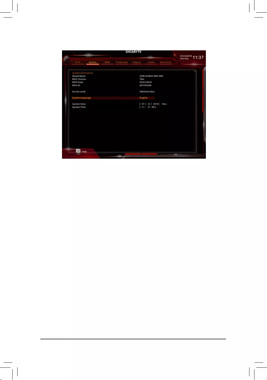
2-4 System
This section provides information on your motherboard model and BIOS version. You can also select the default
language used by the BIOS and manually set the system time.
&Access Level
Displays the current access level depending on the type of password protection used. (If no password is
set, the default will display as Administrator.) The Administrator level allows you to make changes to all
BIOS settings; the User level only allows you to make changes to certain BIOS settings but not all.
&System Language
Selects the default language used by the BIOS.
&System Date
Sets the system date. The date format is week (read-only), month, date, and year. Use <Enter> to switch
betweentheMonth,Date,andYeareldsandusethe<PageUp>or<PageDown>keytosetthedesired
value.
&System Time
Sets the system time. The time format is hour, minute, and second. For example, 1 p.m. is 13:00:00. Use
<Enter>toswitchbetweentheHour,Minute,andSecondeldsandusethe<PageUp>or<PageDown>
key to set the desired value.
— 33 —
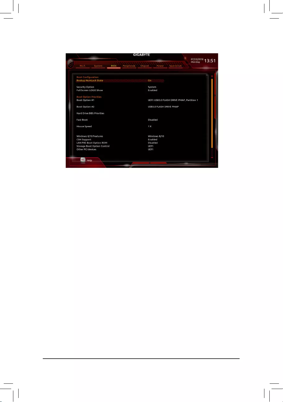
2-5 BIOS
&Bootup NumLock State
Enables or disables Numlock feature on the numeric keypad of the keyboard after the POST. (Default: On)
&Security Option
Specieswhetherapasswordisrequiredeverytimethesystemboots,oronlywhenyouenterBIOSSetup.
Afterconguringthisitem,setthepassword(s)undertheAdministrator Password/User Password item.
Setup A password is only required for entering the BIOS Setup program.
System A password is required for booting the system and for entering the BIOS Setup program.
(Default)
&Full Screen LOGO Show
Allows you to determine whether to display the GIGABYTE Logo at system startup. Disabled skips the
GIGABYTE Logo when the system starts up. (Default: Enabled)
&Boot Option Priorities
Speciestheoverallbootorderfromtheavailabledevices.RemovablestoragedevicesthatsupportGPT
formatwillbeprexedwith«UEFI:»stringonthebootdevicelist.Tobootfromanoperatingsystemthat
supportsGPTpartitioning,selectthedeviceprexedwith»UEFI:»string.
Or if you want to install an operating system that supports GPT partitioning such as Windows 10 64-bit,
selecttheopticaldrivethatcontainstheWindows1064-bitinstallationdiskandisprexedwith«UEFI:»
string.
& Hard Drive/CD/DVD ROM Drive/Floppy Drive/Network Device BBS Priorities
Speciesthebootorderforaspecicdevicetype,suchasharddrives,opticaldrives,oppydiskdrives,
and devices that support Boot from LAN function, etc. Press <Enter> on this item to enter the submenu that
presents the devices of the same type that are connected. This item is present only if at least one device
for this type is installed.
&Fast Boot
Enables or disables Fast Boot to shorten the OS boot process. Ultra Fast provides the fastest bootup
speed. (Default: Disabled)
— 34 —

&SATA Support
Last Boot HDD Only Except for the previous boot drive, all SATA devices are disabled before the OS
boot process completes.
All Sata Devices All SATA devices are functional in the operating system and during the POST.
(Default)
ThisitemiscongurableonlywhenFast Boot is set to Enabled or Ultra Fast.
&VGA Support
Allows you to select which type of operating system to boot.
Auto Enables legacy option ROM only.
EFI Driver Enables EFI option ROM. (Default)
ThisitemiscongurableonlywhenFast Boot is set to Enabled or Ultra Fast.
&USB Support
Disabled All USB devices are disabled before the OS boot process completes.
Full Initial All USB devices are functional in the operating system and during the POST.
Partial Initial Part of the USB devices are disabled before the OS boot process completes.
(Default)
ThisitemiscongurableonlywhenFast Boot is set to Enabled. This function is disabled when Fast Boot
is set to Ultra Fast.
&NetWork Stack Driver Support
Disabled Disables booting from the network. (Default)
Enabled Enables booting from the network.
ThisitemiscongurableonlywhenFast Boot is set to Enabled or Ultra Fast.
&Next Boot After AC Power Loss
Normal Boot Enables normal bootup upon the return of the AC power. (Default)
Fast Boot Keeps the Fast Boot settings upon the return of the AC power.
ThisitemiscongurableonlywhenFast Boot is set to Enabled or Ultra Fast.
&Mouse Speed
Allows you to set the mouse cursor movement speed. (Default: 1 X)
&Windows 8/10 Features
Allows you to select the operating system to be installed. (Default: Window 8/10)
&CSM Support
Enables or disables UEFI CSM (Compatibility Support Module) to support a legacy PC boot process.
Disabled Disables UEFI CSM and supports UEFI BIOS boot process only.
Enabled Enables UEFI CSM. (Default)
&LAN PXE Boot Option ROM
Allows you to select whether to enable the legacy option ROM for the LAN controller. (Default: Disabled)
ThisitemiscongurableonlywhenCSM Support is set to Enabled.
&Storage Boot Option Control
Allows you to select whether to enable the UEFI or legacy option ROM for the storage device controller.
Do not launch Disables option ROM.
UEFI Enables UEFI option ROM only. (Default)
Legacy Enables legacy option ROM only.
ThisitemiscongurableonlywhenCSM Support is set to Enabled.
— 35 —

&Other PCI devices
Allows you to select whether to enable the UEFI or Legacy option ROM for the PCI device controller other
than the LAN, storage device, and graphics controllers.
Do not launch Disables option ROM.
UEFI Enables UEFI option ROM only. (Default)
Legacy Enables legacy option ROM only.
ThisitemiscongurableonlywhenCSM Support is set to Enabled.
&Administrator Password
Allowsyoutocongureanadministratorpassword.Press<Enter>onthisitem,typethepassword,and
thenpress<Enter>.Youwillberequestedtoconrmthepassword.Typethepasswordagainandpress
<Enter>. You must enter the administrator password (or user password) at system startup and when entering
BIOS Setup. Differing from the user password, the administrator password allows you to make changes to
all BIOS settings.
&User Password
Allowsyoutocongureauserpassword.Press<Enter>onthisitem,typethepassword,andthenpress
<Enter>.Youwillberequestedtoconrmthepassword.Typethepasswordagainandpress<Enter>.
You must enter the administrator password (or user password) at system startup and when entering BIOS
Setup. However, the user password only allows you to make changes to certain BIOS settings but not all.
To cancel the password, press <Enter> on the password item and when requested for the password, enter
thecorrectonerst.Whenpromptedforanewpassword,press<Enter>withoutenteringanypassword.
Press<Enter>againwhenpromptedtoconrm.
NOTE:BeforesettingtheUserPassword,besuretosettheAdministratorPasswordrst.
&Secure Boot
AllowsyoutoenableordisableSecureBootandcongurerelatedsettings.Thisitemiscongurableonly
when CSM Support is set to Disabled.
— 36 —
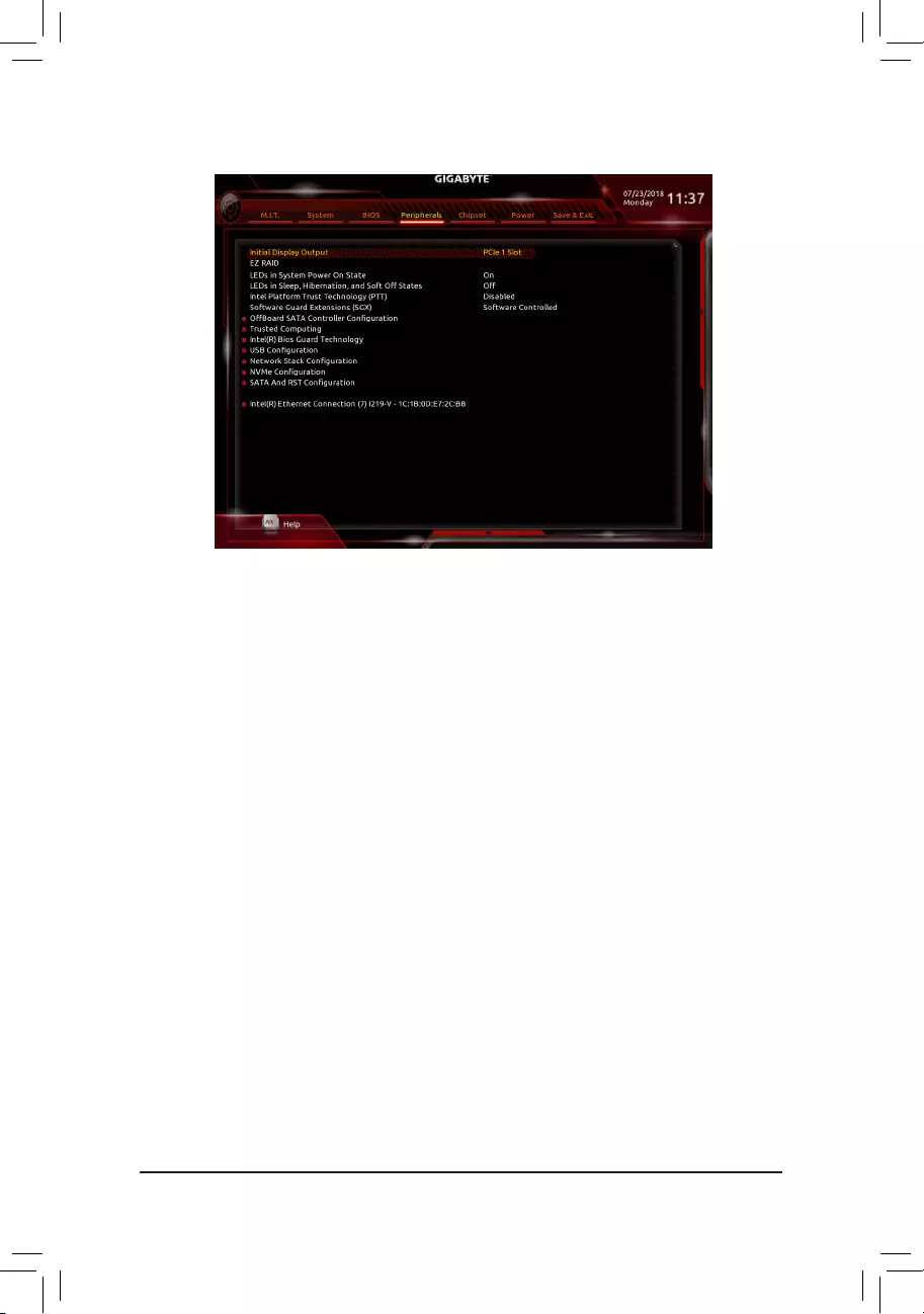
2-6 Peripherals
&Initial Display Output
SpeciestherstinitiationofthemonitordisplayfromtheinstalledPCIExpressgraphicscardortheonboard
graphics.
IGFX Setstheonboardgraphicsastherstdisplay.
PCIe1Slot SetsthegraphicscardonthePCIEX16slotastherstdisplay.(Default)
PCIe2Slot SetsthegraphicscardonthePCIEX8slotastherstdisplay.
PCIe3Slot SetsthegraphicscardonthePCIEX4slotastherstdisplay.
&EZ RAID
AllowsyoutoquicklysetupaRAIDarray.RefertoChapter3,«ConguringaRAIDSet,»forinstructions
onconguringaRAIDarray.
&LEDs in System Power On State
Allows you to enable or disable motherboard LED lighting when the system is on.
Off Disables the selected lighting mode when the system is on. (Default)
On Enables the selected lighting mode when the system is on.
&LEDsinSleep,Hibernation,andSoftOffStates
Allows you to set the lighting mode of the motherboard LEDs in system S3/S4/S5 state.
ThisitemiscongurablewhenLEDs in System Power On State is set to On.
Off Disables the selected lighting mode when the system enters S3/S4/S5 state. (Default)
On Enables the selected lighting mode when the system enters S3/S4/S5 state.
&Intel Platform Trust Technology (PTT)
Enables or disables Intel® PTT Technology. (Default: Disabled)
&Software Guard Extensions (SGX)
Enables or disables the Intel® Software Guard Extensions technology. This feature allows legal software
to operate in a safe environment and protects the software against attacks from malicious software. The
Software Controlled option allows you to enable or disable this feature with an Intel-provided application.
(Default: Software Controlled)
— 37 —

`OffBoardSATAControllerConguration
Displays information on your M.2 PCIe SSD if installed.
`Trusted Computing
Enables or disables Trusted Platform Module (TPM).
`Intel(R) Bios Guard Technology
Enables or disables the Intel® BIOS Guard feature, which protects the BIOS from malicious attacks.
`USBConguration
&Legacy USB Support
Allows USB keyboard/mouse to be used in MS-DOS. (Default: Enabled)
&XHCI Hand-off
Determines whether to enable XHCI Hand-off feature for an operating system without XHCI Hand-off
support. (Default: Disabled)
&USB Mass Storage Driver Support
Enables or disables support for USB storage devices. (Default: Enabled)
&Port 60/64 Emulation
Enables or disables emulation of I/O ports 64h and 60h. This should be enabled for full legacy support
for USB keyboards/mice in MS-DOS or in operating system that does not natively support USB devices.
(Default: Disabled)
&Mass Storage Devices
Displays a list of connected USB mass storage devices. This item appears only when a USB storage device
is installed.
`NetworkStackConguration
&Network Stack
Disables or enables booting from the network to install a GPT format OS, such as installing the OS from
the Windows Deployment Services server. (Default: Disabled)
&Ipv4 PXE Support
EnablesordisablesIPv4PXESupport.ThisitemiscongurableonlywhenNetwork Stack is enabled.
&Ipv4 HTTP Support
EnablesordisablesHTTPbootsupportforIPv4.ThisitemiscongurableonlywhenNetwork Stack is
enabled.
&Ipv6 PXE Support
EnablesordisablesIPv6PXESupport.ThisitemiscongurableonlywhenNetwork Stack is enabled.
&Ipv6 HTTP Support
EnablesordisablesHTTPbootsupportforIPv6.ThisitemiscongurableonlywhenNetwork Stack is
enabled.
&IPSECCerticate
EnablesordisablestheInternetProtocolSecurity.ThisitemiscongurableonlywhenNetwork Stack is
enabled.
&PXE boot wait time
Allowsyoutocongurehowlongtowaitbeforeyoucanpress<Esc>toabortthePXEboot.Thisitemis
congurableonlywhenNetwork Stack is enabled. (Default: 0)
&Media detect count
Allowsyoutosetthenumberoftimestocheckthepresenceofmedia.Thisitemiscongurableonlywhen
Network Stack is enabled. (Default: 1)
— 38 —

`NVMeConguration
Displays information on your M.2 NVME PCIe SSD if installed.
`SATAAndRSTConguration
&SATA Controller(s)
Enables or disables the integrated SATA controllers. (Default: Enabled)
&SATA Mode Selection
EnablesordisablesRAIDfortheSATAcontrollersintegratedintheChipsetorcongurestheSATAcontrollers
to AHCI mode.
Intel RST Premium With Intel Optane System Acceleration Enables RAID for the SATA controller.
AHCI CongurestheSATAcontrollerstoAHCImode.AdvancedHostControllerInterface
(AHCI)isaninterfacespecicationthatallowsthestoragedrivertoenableadvanced
Serial ATA features such as Native Command Queuing and hot plug. (Default)
&Aggressive LPM Support
Enables or disables the power saving feature, ALPM (Aggressive Link Power Management), for the Chipset
SATA controllers. (Default: Enabled)
&Port 0/1/2/3/4/5
Enables or disables each SATA port. (Default: Enabled)
&Hot plug
Enables or disable the hot plug capability for each SATA port. (Default: Disabled)
&ConguredaseSATA
Enables or disables support for external SATA devices.
— 39 —
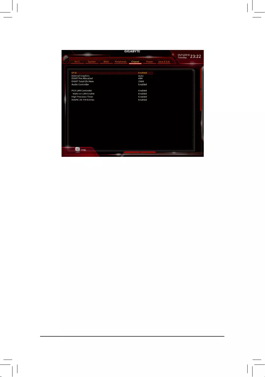
2-7 Chipset
(Note) This item is present only when you install a CPU that supports this feature. For more information about
Intel® CPUs’ unique features, please visit Intel’s website.
&VT-d (Note)
Enables or disables Intel® Virtualization Technology for Directed I/O. (Default: Enabled)
&Internal Graphics
Enables or disables the onboard graphics function. (Default: Auto)
&DVMT Pre-Allocated
Allows you to set the onboard graphics memory size. Options are: 32M~1024M. (Default: 64M)
&DVMT Total Gfx Mem
Allows you to allocate the DVMT memory size of the onboard graphics. Options are: 128M, 256M, MAX.
(Default: 256M)
&Audio Controller
Enables or disables the onboard audio function. (Default: Enabled)
If you wish to install a 3rd party add-in audio card instead of using the onboard audio, set this item to
Disabled.
&Above 4G Decoding
Enables or disables 64-bit capable devices to be decoded in above 4 GB address space (only if your system
supports 64-bit PCI decoding). Set to Enabled if more than one advanced graphics card are installed and
their drivers are not able to be launched when entering the operating system (because of the limited 4 GB
memory address space). (Default: Disabled)
&PCH LAN Controller
Enables or disables the Intel® GbE LAN function. (Default: Enabled)
If you wish to install a 3rd party add-in network card instead of using the onboard LAN, set this item to
Disabled.
&Wake on LAN Enable
Enables or disables the wake on LAN function. (Default: Enabled)
&IOAPIC 24-119 Entries
Enables or disables this function. (Default: Enabled)
— 40 —
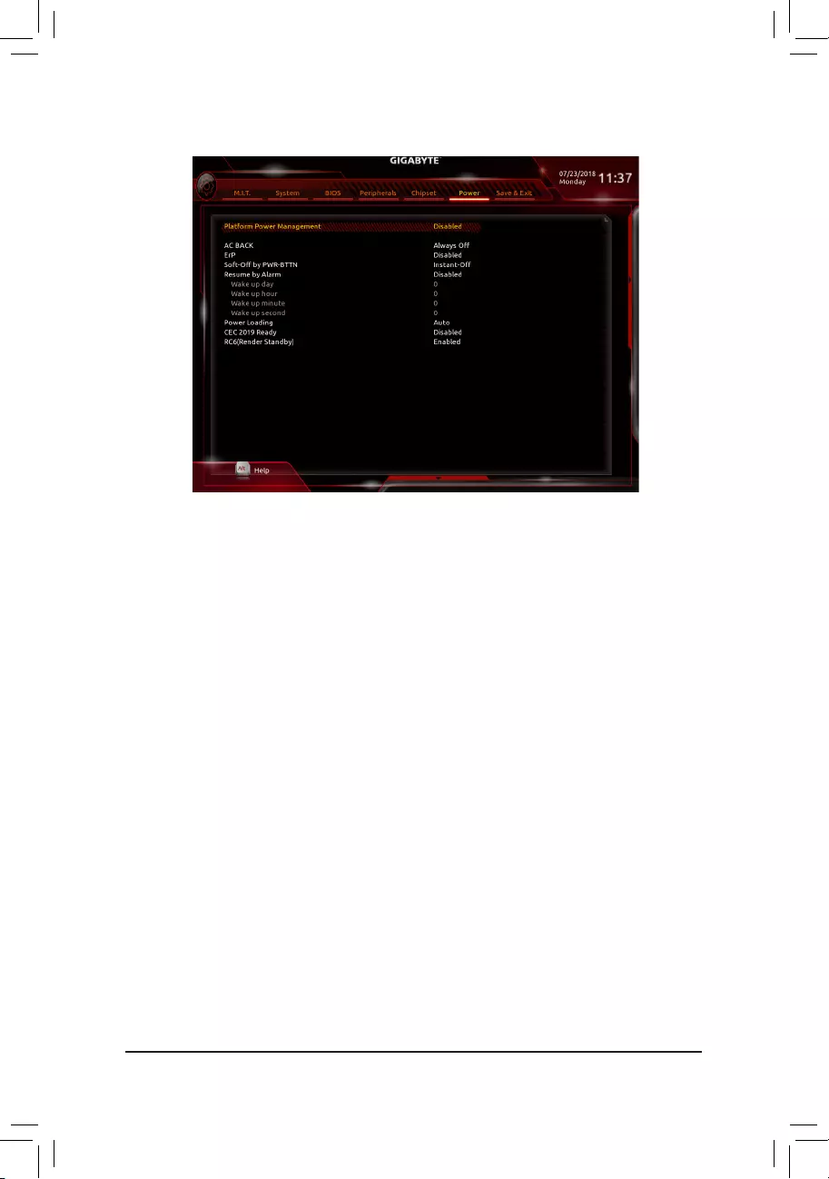
2-8 Power
&Platform Power Management
Enables or disables the Active State Power Management function (ASPM). (Default: Disabled)
&PEG ASPM
Allowsyou tocongure theASPM modefor thedevice connectedto theCPUPEGbus.This itemis
congurableonlywhenPlatform Power Management is set to Enabled. (Default: Disabled)
&PCH ASPM
AllowsyoutoconguretheASPMmodeforthedeviceconnectedtoChipset’sPCIExpressbus.Thisitem
iscongurableonlywhenPlatform Power Management is set to Enabled. (Default: Disabled)
&DMI ASPM
AllowsyoutoconguretheASPMmodeforbothCPUsideandChipsetsideoftheDMIlink.Thisitemis
congurableonlywhenPlatform Power Management is set to Enabled. (Default: Disabled)
&AC BACK
Determines the state of the system after the return of power from an AC power loss.
Memory The system returns to its last known awake state upon the return of the AC power.
Always On The system is turned on upon the return of the AC power.
Always Off The system stays off upon the return of the AC power. (Default)
&ErP
Determines whether to let the system consume least power in S5 (shutdown) state. (Default: Disabled)
Note: When this item is set to Enabled, the following functions will become unavailable: Resume by Alarm,
power on by mouse, and power on by keyboard.
&Soft-Off by PWR-BTTN
ConguresthewaytoturnoffthecomputerinMS-DOSmodeusingthepowerbutton.
Instant-Off Press the power button and then the system will be turned off instantly. (Default)
Delay 4 Sec. Press and hold the power button for 4 seconds to turn off the system. If the power
button is pressed for less than 4 seconds, the system will enter suspend mode.
— 41 —

&Resume by Alarm
Determines whether to power on the system at a desired time. (Default: Disabled)
If enabled, set the date and time as following:
Wakeupday:Turnonthesystemataspecictimeoneachdayoronaspecicdayinamonth.
Wake up hour/minute/second: Set the time at which the system will be powered on automatically.
Note: When using this function, avoid inadequate shutdown from the operating system or removal of the
AC power, or the settings may not be effective.
&Power Loading
Enables or disables dummy load. When the power supply is at low load, a self-protection will activate causing
it to shutdown or fail. If this occurs, please set to Enabled. AutoletstheBIOSautomaticallycongurethis
setting. (Default: Auto)
&CEC 2019 Ready
Allows you to select whether to allow the system to adjust power consumption when it is in shutdown, idle,
or standby state in order to comply with the CEC (California Energy Commission) 2019 Standards. (Default:
Disabled)
&RC6(Render Standby)
Allows you to determine whether to let the onboard graphics enter standby mode to decrease power
consumption. (Default: Enabled)
— 42 —
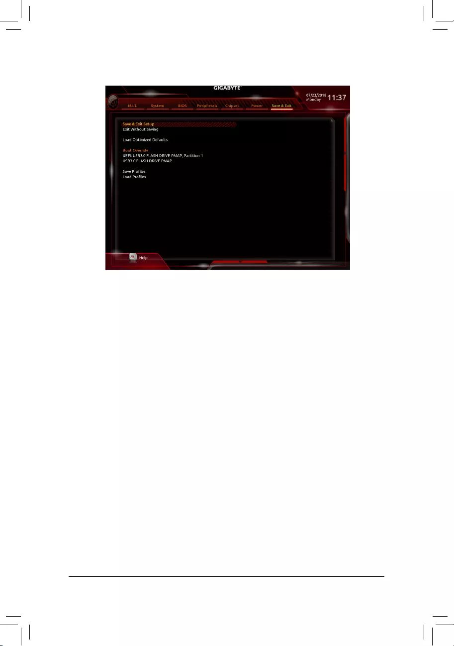
2-9 Save & Exit
&Save & Exit Setup
Press <Enter> on this item and select Yes. This saves the changes to the CMOS and exits the BIOS Setup
program. Select No or press <Esc> to return to the BIOS Setup Main Menu.
&Exit Without Saving
Press <Enter> on this item and select Yes. This exits the BIOS Setup without saving the changes made
in BIOS Setup to the CMOS. Select No or press <Esc> to return to the BIOS Setup Main Menu.
&Load Optimized Defaults
Press <Enter> on this item and select Yes to load the optimal BIOS default settings. The BIOS defaults
settings help the system to operate in optimum state. Always load the Optimized defaults after updating
the BIOS or after clearing the CMOS values.
&Boot Override
Allows you to select a device to boot immediately. Press <Enter> on the device you select and select Yes
toconrm.Yoursystemwillrestartautomaticallyandbootfromthatdevice.
&SaveProles
ThisfunctionallowsyoutosavethecurrentBIOSsettingstoaprole.Youcancreateupto8prolesand
saveasSetupProle1~SetupProle8.Press<Enter>tocomplete.OryoucanselectSelect File in
HDD/FDD/USBtosavetheproletoyourstoragedevice.
&LoadProles
If your system becomes unstable and you have loaded the BIOS default settings, you can use this function
toloadtheBIOS settingsfromaprolecreatedbefore,withoutthehasslesof reconguringtheBIOS
settings.Firstselecttheproleyouwishtoloadandthenpress<Enter>tocomplete.YoucanselectSelect
File in HDD/FDD/USBtoinputtheprolepreviouslycreatedfromyourstoragedeviceorloadtheprole
automatically created by the BIOS, such as reverting the BIOS settings to the last settings that worked
properly (last known good record).
— 43 —
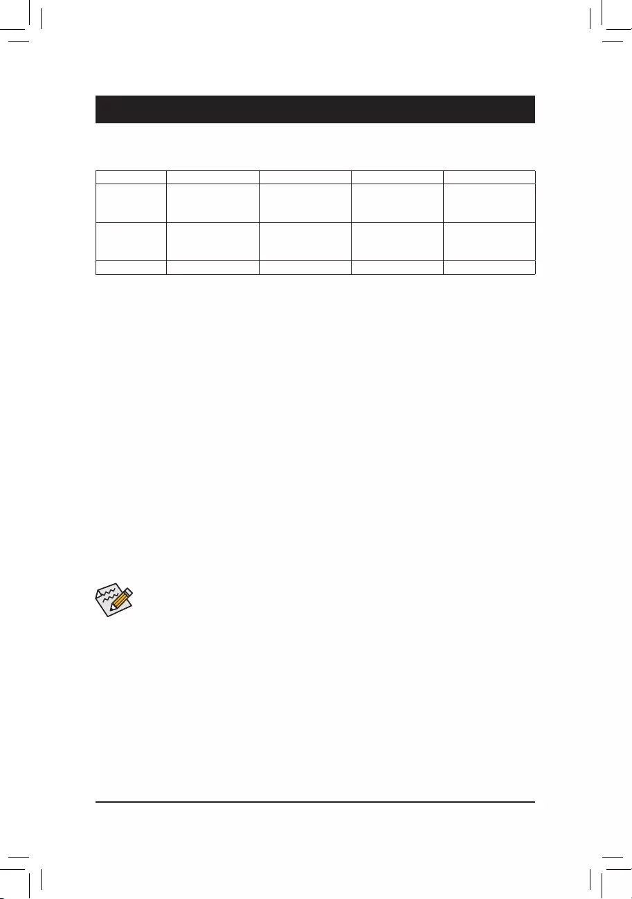
Chapter 3 Appendix
Beforeyoubegin,pleasepreparethefollowingitems:
•At least two SATA hard drives or SSDs. (Note 1) (To ensure optimal performance, it is recommended that you
use two hard drives with identical model and capacity). (Note 2)
•Windows setup disk.
•Motherboard driver disk.
•A USB thumb drive.
ConguringtheOnboardSATAController
A. Installing SATA hard drive(s) in your computer
Install the hard drives/SSDs in the Intel® Chipset controlled connectors on the motherboard. Then connect the
power connectors from your power supply to the hard drives.
B.ConguringSATAcontrollermodeinBIOSSetup
MakesuretoconguretheSATAcontrollermodecorrectlyinsystemBIOSSetup.
Steps:
1. Go to PeripheralsSATAAndRSTConguration, make sure SATA Controller(s) is enabled. To create
RAID, set SATA Mode Selection to Intel RST Premium With Intel Optane System Acceleration. Then
save the settings and restart your computer. Note: When using a PCIe SSD, make sure to set the Use RST
Legacy OROM item under PeripheralsSATAAndRSTConguration to Disabled. Then depending the
M.2 connector you use, set the corresponding PCIe Storage Dev On Port XX item to RST Controlled.
2. TousetheEZRAIDfeature,followthestepsin»C-1.»TocongureUEFIRAID,followthestepsin»C-2.»To
enter the legacy RAID ROM, refer to «C-3» for more information. Finally, save the settings and exit BIOS Setup.
3-1 ConguringaRAIDSet
RAID Levels
The BIOS Setup menus described in this section may differ from the exact settings for your motherboard.
The actual BIOS Setup menu options you will see shall depend on the motherboard you have and
the BIOS version.
(Note 1) An M.2 PCIe SSD cannot be used to set up a RAID set either with an M.2 SATA SSD or a SATA hard
drive.
(Note 2) Refer to «1-8 Internal Connectors,» for the installation notices for the M.2 and SATA connectors.
C-1. Using EZ RAID
GIGABYTEmotherboardsprovideyouwiththe EZRAIDfeature,allowingyoutoquickly congureaRAID
arraywithsimpliedsteps.
Steps:
1. After restarting the computer, enter the BIOS Setup and go to Peripherals. Press <Enter> on the EZ RAID
item. Select the type of hard drives you use for RAID in the Type tab and then press <Enter>.
2. Go to the Mode tab to select a RAID level. RAID levels supported include RAID 0, RAID 1, RAID 10, and
RAID 5 (the selections available depend on the number of the hard drives being installed). Then press
<Enter> to move to the Create tab. Click Proceed to begin.
RAID 0 RAID 1 RAID 5 RAID 10
Minimum
Number of Hard
Drives
≥2 2≥3 4
Array Capacity Number of hard
drives * Size of the
smallest drive
Size of the smallest
drive
(Number of hard
drives -1) * Size of
the smallest drive
(Number of hard
drives/2) * Size of the
smallest drive
Fault Tolerance No Yes Yes Yes
— 44 —

C-3.ConguringLegacyRAIDROM
Enter the Intel®legacyRAIDBIOSsetuputilitytocongureaRAIDarray.Skipthisstepandproceedwiththe
installationofWindowsoperatingsystemforanon-RAIDconguration.
Steps:
1. In BIOS Setup, go to BIOS and set CSM Support to Enabled and Storage Boot Option Control to Legacy.
Next, go to PeripheralsSATAAndRSTConguration and make sure Use RST Legacy OROM is set
to Enabled. Save the changes and exit BIOS Setup. After the POST memory test begins and before the
operatingsystembootbegins,lookforamessagewhichsays«Press<Ctrl-I>toenterCongurationUtility».
Press<Ctrl>+<I>toentertheRAIDCongurationUtility.
2. After you press <Ctrl> + <I>, the MAIN MENU screen will appear. If you want to create a RAID array, select
Create RAID Volume in MAIN MENU and press <Enter>.
3. After entering the CREATE VOLUME MENU screen, enter a volume name with 1~16 letters (letters cannot
be special characters) under the Name item and press <Enter>. Then, select a RAID level. RAID levels
supported include RAID 0, RAID 1, RAID 10, and RAID 5 (the selections available depend on the number of
the hard drives being installed). Press <Enter> to proceed.
4. Under Disks item, select the hard drives to be included in the RAID array. If only two hard drives are installed,
they will be automatically assigned to the array. Set the stripe block size if necessary. The stripe block size
can be set from 4 KB to 128 KB. Once you have selected the stripe block size, press <Enter>.
5. Enter the array capacity and press <Enter>. Finally press <Enter> on the Create Volume item to begin
creatingtheRAIDarray.Whenpromptedtoconrmwhethertocreatethisvolume,press<Y>toconrmor
<N> to cancel.
6. When completed, you can see detailed information about the RAID array in the DISK/VOLUME INFORMATION
section, including the RAID level, stripe block size, array name, and array capacity, etc. To exit the RAID
BIOS utility, press <Esc> or select 6. Exit in MAIN MENU.
C-2.UEFIRAIDConguration
Steps:
1. In BIOS Setup, go to BIOS and set CSM Support to Disabled. Save the changes and exit BIOS Setup.
2. After the system reboot, enter BIOS Setup again. Then enter the PeripheralsIntel(R) Rapid Storage
Technology sub-menu.
3. On the Intel(R) Rapid Storage Technology menu, press <Enter> on Create RAID Volume to enter the
Create RAID Volume screen. Enter a volume name with 1~16 letters (letters cannot be special characters)
under the Name item and press <Enter>. Then, select a RAID level. RAID levels supported include RAID
0, RAID 1, RAID 10, and RAID 5 (the selections available depend on the number of the hard drives being
installed). Next, use the down arrow key to move to Select Disks.
4. Under Select Disks item, select the hard drives to be included in the RAID array. Press the <Space> key
on the hard drives to be selected (selected hard drives are marked with «X»). Then set the stripe block size.
The stripe block size can be set from 4 KB to 128 KB. Once you have selected the stripe block size, set the
volume capacity.
5. After setting the capacity, move to Create Volume and press <Enter> to begin.
6. After completing, you’ll be brought back to the Intel(R) Rapid Storage Technology screen. Under RAID
Volumes you can see the new RAID volume. To see more detailed information, press <Enter> on the volume
to check for information on RAID level, stripe block size, array name, and array capacity, etc.
PleasevisitGIGABYTE’swebsitefordetailsonconguringaRAIDarray.
3. After completing, you’ll be brought back to the Intel(R) Rapid Storage Technology screen. Under RAID
Volumes you can see the new RAID volume. To see more detailed information, press <Enter> on the volume
to check for information on RAID level, stripe block size, array name, and array capacity, etc.
— 45 —

Installing the RAID/AHCI Driver and Operating System
With the correct BIOS settings, you are ready to install the operating system.
Installing the Operating System
As some operating systems already include RAID/AHCI driver, you do not need to install separate RAID/AHCI
driver during the Windows installation process. After the operating system is installed, we recommend that you
install all required drivers from the motherboard driver disk using «Xpress Install» to ensure system performance
and compatibility. If the operating system to be installed requires that you provide additional SATA RAID/AHCI
driver during the OS installation process, please refer to the steps below:
1. Copy the IRST folder under Boot in the driver disk to your USB thumb drive.
2. Boot from the Windows setup disk and perform standard OS installation steps. When the screen requesting
you to load the driver appears, select Browse.
3. ThenbrowsetotheUSBashdriveandselectthelocationofthedriver.Thelocationofthedriverisas
follows:IRSTf6py-x64
4. When a screen as shown, select Intel Chipset SATA RAID Controller and click Next to load the driver and
continue the OS installation.
3-2 Installing an Intel® Optane™ Memory
System Requirements
1. Intel® Optane™ memory.
2. The Optane™ memory must have at least 16 GB capacity, and it must have equal or smaller capacity than
the hard drive/SSD to be accelerated.
3. The Optane™ memory cannot be used to accelerate an existing RAID array; the accelerated hard drive/SSD
cannot be included in a RAID array.
4. The hard drive/SSD to be accelerated must be a SATA hard drive or M.2 SATA SSD.
5. The hard drive/SSD to be accelerated can be a system drive or data drive. The system drive must be GPT formatted
and have Windows 10 64-bit (or later version) installed on it. The data drive must also be GPT formatted.
6. The motherboard driver disk.
Installation Guidelines
A-1: Installation in AHCI mode
IftheSATAcontrollerhasbeenconguredinAHCImode,pleasefollowthestepsbelow:
1. After entering the operating system, insert the motherboard driver disk into your optical drive. On the Xpress
Install screen, select Intel(R) Optane(TM) Memory System Acceleration (Note) to install. Follow the on-screen
instructions to continue. When completed, restart the system.
2. After re-entering the operating system, follow the on-screen instructions to complete the settings, and then the
Intel® Optane™ Memory application will appear automatically. If you install more than one Optane™ memory,
please select which one you are going to use. Then select which drive to be accelerated. Click Enable. All
data on the Optane™ memory will be erased. Make sure you back up the data before continuing. Follow the
on-screen instructions to proceed. When completed, restart the system.
3. Launch the Intel® Optane™ Memory application from the Start menu and make sure the Intel® Optane™
Memory has been enabled. (The SATA controller mode is changed to «Intel RST Premium With Intel Optane
System Acceleration» from AHCI mode. DO NOT change your SATA controller mode back to AHCI. Doing
so will cause the Optane™ memory unable to function properly.)
4. Ifyouwanttoacceleratethesystemdrive,youcanselectspecicfolders,les,orapplicationstoaccelerateusing
the Intel® Optane™ Memory Pinning function. (The Optane™ memory used must have at least 32 GB capacity.)
(Note) If the system already has Intel®RapidStorageTechnologyutilityinstalled,youhavetoremoveitrst
before installing the Intel(R) Optane(TM) Memory System Acceleration application.
— 46 —

A-2: Installation in Intel RST Premium With Intel Optane System Acceleration mode
IftheSATAcontrollerhasbeenconguredinIntelRSTPremiumWithIntelOptaneSystemAccelerationmode,
please follow the steps below:
1. After system restarts, go to the BIOS Setup, make sure CSM Support under the BIOS menu is disabled.
2. Go to PeripheralsSATAAndRSTConguration and make sure USE RST Legacy OROM is disabled. If
you want to enable the Optane™ memory installed in the M2M connector, set PCIe Storage Dev on Port 17
to RST Controlled; to enable the Optane™ memory installed in the M2A connector, set PCIe Storage Dev
on Port 9 to RST Controlled.
3. Enter the operating system, launch the Intel® Rapid Storage Technology utility from the Start menu, and
then enable Intel® Optane™ Memory on the Intel® Optane™ Memory tab.
4. If you install more than one Optane™ memory, please select which one you are going to use. Then select
which drive to be accelerated. Click Yes to continue. Follow the on-screen instructions to proceed. When
completed, restart the system.
5. Launch the Intel® Rapid Storage Technology utility from the Start menu and make sure the Intel® Optane™
Memoryhasbeenenabled.Ifyouwanttoacceleratethesystemdrive,youcanselectspecicfolders,les,
or applications to accelerate using the Intel® Optane™ Memory Pinning function. (The Optane™ memory
used must have at least 32 GB capacity.)
•An Optane™ memory cannot be used to accelerate an M.2 PCIe SSD.
•If more than one Optane™ memory is installed, you can select only one of them to accelerate your
SATA-based boot drive. The other(s) can only be used as data drive(s).
•Do not abruptly remove the Optane™ memory. Doing so will cause the operating system to stop
functioning correctly.
•If you want to change/remove the Optane™ memory, you must disable it using the Intel® Rapid
StorageTechnologyorIntel(R)OptaneMemoryapplicationrst.
•After enabling the Optane™ memory, the related BIOS settings will remain even after a BIOS update.
— 47 —
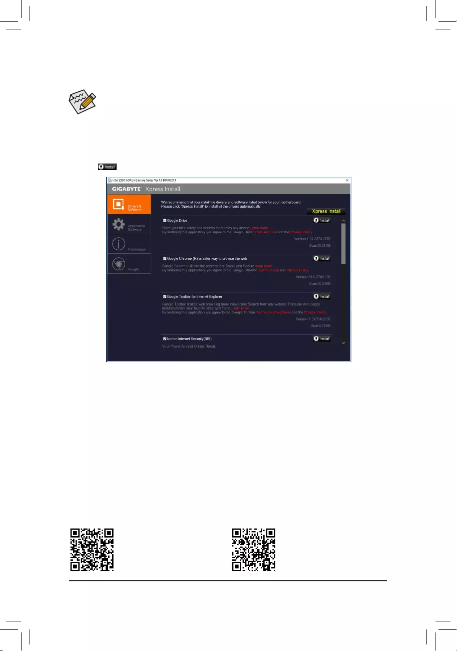
•Beforeinstallingthedrivers,rstinstalltheoperatingsystem.
•After installing the operating system, insert the motherboard driver disk into your optical drive. Click
on the message «Tap to choose what happens with this disc» on the top-right corner of the screen
and select «Run Run.exe.» (Or go to My Computer, double-click the optical drive and execute the
Run.exe program.)
«Xpress Install» will automatically scan your system and then list all of the drivers that are recommended to
install. You can click the Xpress Install button and «Xpress Install» will install all of the selected drivers. Or click
the arrow icon to individually install the drivers you need.
3-3 Drivers Installation
Please visit GIGABYTE’s website for
more software information.
Please visit GIGABYTE’s website for
more troubleshooting information.
— 48 —
Regulatory Statements
Regulatory Notices
This document must not be copied without our written permission, and the contents there of must not be imparted to a
third party nor be used for any unauthorized purpose.
Contravention will be prosecuted. We believe that the information contained herein was accurate in all respects at the
time of printing. GIGABYTE cannot, however, assume any responsibility for errors or omissions in this text. Also note
that the information in this document is subject to change without notice and should not be construed as a commitment
by GIGABYTE.
Our Commitment to Preserving the Environment
Inadditiontohigh-efciencyperformance,allGIGABYTEmotherboardsfulllEuropeanUnionregulationsforRoHS
(Restriction of Certain Hazardous Substances in Electrical and Electronic Equipment) and WEEE (Waste Electrical and
Electronic Equipment) environmental directives, as well as most major worldwide safety requirements. To prevent releases
of harmful substances into the environment and to maximize the use of our natural resources, GIGABYTE provides the
following information on how you can responsibly recycle or reuse most of the materials in your «end of life» product.
Restriction of Hazardous Substances (RoHS) Directive Statement
GIGABYTE products have not intended to add and safe from hazardous substances (Cd, Pb, Hg, Cr+6, PBDE and
PBB). The parts and components have been carefully selected to meet RoHS requirement. Moreover, we at GIGABYTE
are continuing our efforts to develop products that do not use internationally banned toxic chemicals.
Waste Electrical & Electronic Equipment (WEEE) Directive Statement
GIGABYTEwillfulllthenationallawsasinterpretedfromthe2002/96/ECWEEE(WasteElectricalandElectronic
Equipment)directive.TheWEEEDirectivespeciesthetreatment,collection,recyclinganddisposalofelectricand
electronic devices and their components. Under the Directive, used equipment must be marked, collected separately,
and disposed of properly.
WEEE Symbol Statement
The symbol shown below is on the product or on its packaging, which indicates that this product must
not be disposed of with other waste. Instead, the device should be taken to the waste collection centers
for activation of the treatment, collection, recycling and disposal procedure. The separate collection and
recycling of your waste equipment at the time of disposal will help to conserve natural resources and ensure
that it is recycled in a manner that protects human health and the environment. For more information about where you
candropoffyourwasteequipmentforrecycling,pleasecontactyourlocalgovernmentofce,yourhouseholdwaste
disposal service or where you purchased the product for details of environmentally safe recycling.
When your electrical or electronic equipment is no longer useful to you, «take it back» to your local or regional waste
collection administration for recycling.
If you need further assistance in recycling, reusing in your «end of life» product, you may contact us at the Customer
Care number listed in your product’s user’s manual and we will be glad to help you with your effort.
Finally, we suggest that you practice other environmentally friendly actions by understanding and using the energy-saving
features of this product (where applicable), recycling the inner and outer packaging (including shipping containers) this
product was delivered in, and by disposing of or recycling used batteries properly. With your help, we can reduce the
amountofnaturalresourcesneededtoproduceelectricalandelectronicequipment,minimizetheuseoflandllsfor
the disposal of «end of life» products, and generally improve our quality of life by ensuring that potentially hazardous
substances are not released into the environment and are disposed of properly.
Battery Information
European Union—Disposal and recycling information
GIGABYTE Recycling Program (available in some regions)
This symbol indicates that this product and/or battery should not be disposed of with household waste. You must use
the public collection system to return, recycle, or treat them in compliance with the local regulations.
— 49 —

FCC Notice (U.S.A. Only)
Operation is subject to the following two conditions: (1) this device may not cause harmful interference, and (2)
this device must accept any interference received, including interference that may cause undesired operation.
WARNING: This equipment has been tested and found to comply with the limits for a Class B digital device,
pursuant to Part 15 of the FCC Rules. These limits are designed to provide reasonable protection against harmful
interference in a residential installation.
This equipment generates and radiates radio frequency energy and, if not installed and used in accordance
with the instructions, may cause harmful interference to radio communications.
However, there is no guarantee that interference will not occur in a particular installation. If this equipment does
cause harmful interference to radio or television reception, which can be determined by turning the equipment
off and on, the user is encouraged to try to correct the interference by one or more of the following measures:
•Reorient or relocate the receiving antenna.
•Increase the separation between the equipment and receiver.
•Connect the equipment into an outlet on a circuit different from that to which the receiver is connected.
•Consult a dealer or experienced TV/radio technician for help.
TheusermayndthefollowingbookletpreparedbytheFederalCommunicationsCommissionhelpful:
The Interference Handbook.
ThisbookletisavailablefromtheU.S.GovernmentPrintingOfce,Washington,D.C.20402.StockNo.004-
000-00345-4
Notice for 5GHz
Operations in the 5.15-5.25GHz band are restricted to indoor usage only. (For 5GHz only)
RF exposure statement
The product comply with the FCC portable RF exposure limit set forth for an uncontrolled environment and are
safe for intended operation as described in this manual. The further RF exposure reduction can be achieved if
the product can be kept as far as possible from the user body or set the device to lower output power if such
function is available.
CAUTION:
The manufacturer is not responsible for any interference caused by unauthorized
modicationsand/oruseofunauthorizedantennas.
Suchchangesand/ormodicationsnotexpresslyapprovedbythepartyresponsiblefor
compliance of this device could void the user’s authority to operate the equipment.
— 50 —

Canada-Industry Canada (IC):
This device complies with Canadian RSS-210.
This device complies with Industry Canada license-exempt RSS standard(s). Operation is subject to the
following two conditions:
(1) this device may not cause interference, and
(2) this device must accept any interference, including interference that may cause undesired operation of
the device.
Ce dispositif est conforme à la norme CNR-210 d’Industrie Canada applicable aux appareils radio exempts de
licence. Son fonctionnement est sujet aux deux conditions suivantes:
(1) le dispositif ne doit pas produire de brouillage préjudiciable, et
(2) ce dispositif doit accepter tout brouillage reçu, y compris un brouillage susceptible de provoquer un
fonctionnement indésirable.
Notice for 5GHz:
Caution :
(i) the device for operation in the band 5150-5250 MHz is only for indoor use to reduce the potential for harmful
interference to co-channel mobile satellite systems;
(ii) the maximum antenna gain permitted for devices in the bands 5250-5350 MHz and 5470-5725 MHz shall
comply with the e.i.r.p. limit; and
(iii) the maximum antenna gain permitted for devices in the band 5725-5825 MHz shall comply with the e.i.r.p.
limitsspeciedforpoint-to-pointandnonpoint-to-pointoperationasappropriate.
(iv) Users should also be advised that high-power radars are allocated as primary users (i.e. priority users)
of the bands 5250-5350 MHz and 5650-5850 MHz and that these radars could cause interference and/or
damage to LE-LAN devices.
Avertissement:
Le guide d’utilisation des dispositifs pour réseaux locaux doit inclure des instructions précises sur les restrictions
susmentionnées, notamment :
(i) les dispositifs fonctionnant dans la bande 5 150-5 250 MHz sont réservés uniquement pour une utilisation à
l’intérieuranderéduirelesrisquesdebrouillagepréjudiciableauxsystèmesdesatellitesmobilesutilisant
les mêmes canaux;
(ii) le gain maximal d’antenne permis pour les dispositifs utilisant les bandes 5 250-5 350 MHz et 5 470-5 725
MHz doit se conformer à la limite de p.i.r.e.;
(iii) le gain maximal d’antenne permis (pour les dispositifs utilisant la bande 5 725-5 825 MHz) doit se conformer
àlalimitedep.i.r.e.spéciéepourl’exploitationpointàpointetnonpointàpoint,selonlecas.
(iv) De plus, les utilisateurs devraient aussi être avisés que les utilisateurs de radars de haute puissance sont
désignés utilisateurs principaux (c.-à-d., qu’ils ont la priorité) pour les bandes 5 250-5 350 MHz et 5 650-5
850 MHz et que ces radars pourraient causer du brouillage et/ou des dommages aux dispositifs LAN-EL.
Radiation Exposure Statement:
The product comply with the Canada portable RF exposure limit set forth for an uncontrolled environment and
are safe for intended operation as described in this manual. The further RF exposure reduction can be achieved
if the product can be kept as far as possible from the user body or set the device to lower output power if such
function is available.
— 51 —

European Community Radio Equipment Directive (RED) Compliance Statement:
This equipment complies with all the requirements and other relevant provisions of Radio Equipment Directive
2014/53/EU.
ThisequipmentissuitableforhomeandofceuseinalltheEuropeanCommunityMemberStatesandEFTA
Member States.
The low band 5.15 -5.35 GHz is for indoor use only.
Restrictions d’utilisation en France:
Pour la France métropolitaine
2.400 — 2.4835 GHz (Canaux 1à 13) autorisé en usage intérieur
2.400 — 2.454 GHz (canaux 1 à 7) autorisé en usage extérieur
Pour la Guyane et la Réunion
2.400 — 2.4835 GHz (Canaux 1à 13) autorisé en usage intérieur
2.420 — 2.4835 GHz (canaux 5 à 13) autorisé en usage extérieur
Notice for Italy:
The use of these equipments is regulated by:
1. D.L.gs 1.8.2003, n. 259, article 104 (activity subject to general authorization) for outdoor use and article
105 (free use) for indoor use, in both cases for private use.
2. D.M. 28.5.03, for supply to public of RLAN access to networks and telecom services. L’uso degli apparati
èregolamentatoda:
1. D.L.gs 1.8.2003, n. 259, articoli 104 (attività soggette ad autorizzazione generale) se utilizzati al di fuori
del proprio fondo e 105 (libero uso) se utilizzati entro il proprio fondo, in entrambi i casi per uso private.
2. D.M. 28.5.03, per la fornitura al pubblico dell’accesso R-LAN alle reti e ai servizi di telecomunicazioni.
Taiwan NCC Wireless Statements / 無線設備警告聲明:
低功率電波輻射性電機管理辦法
第十二條: 經型式認證合格之低功率射頻電機,非經許可,公司、商號或使用者均不得擅自變更頻
率、加大功率或變更原設計之特性及功能。
第十四條: 低功率射頻電機之使用不得影響飛航安全及干擾合法通信;經發現有干擾現象時,應立
即停用,並改善至無干擾時方得繼續使用。前項合法通信,指依電信法規定作業之無線
電通信。低功率射頻電機須忍受合法通信或工業、科學及醫療用電波輻射性電機設備之
干擾。
在5.25-5.35秭赫頻帶內操作之無線資訊傳輸設備,限於室內使用。
Korea KCC NCC Wireless Statement:
5,25 GHz — 5,35 GHz 대역을 사용하는 무선 장치는 실내에서만 사용하도록 제한됩니다。
Japan Wireless Statement:
5.15GHz帯 ~ 5.35GHz帯: 屋内のみの使用。
— 52 —

— 53 —

— 54 —

— 55 —
Contact Us
GIGA-BYTETECHNOLOGYCO.,LTD.
Address: No.6, Baoqiang Rd., Xindian Dist., New Taipei City 231, Taiwan
TEL: +886-2-8912-4000, FAX: +886-2-8912-4005
Tech. and Non-Tech. Support (Sales/Marketing) : https://esupport.gigabyte.com
WEB address (English): https://www.gigabyte.com
WEB address (Chinese): https://www.gigabyte.com/tw
•GIGABYTE eSupport
To submit a technical or non-technical (Sales/Marketing) question, please link to:
https://esupport.gigabyte.com
— 56 —
Z390 AORUS PRO
WIFI
User’s Manual
Rev. 1001
12ME-Z39PROW-1001R
Z390 AORUS
PRO
Z390 AORUS
PRO WIFI
For more product details, please visit GIGABYTE’s website.
To reduce the impacts on global warming, the packaging materials of this product are recyclable and reusable. GIGABYTE works with you to protect the environment.
Motherboard
Z390 AORUS PRO WIFI
Aug. 31, 2018
Wireless Module Country Approvals:
Motherboard
Z390 AORUS PRO WIFI
Aug. 31, 2018
— 2 —
Motherboard
Z390 AORUS PRO
Motherboard
Z390 AORUS PRO
Aug. 31, 2018
Aug. 31, 2018
Copyright
©
2018 GIGA-BYTE TECHNOLOGY CO., LTD. All rights reserved.
The trademarks mentioned in this manual are legally registered to their respective owners.
Disclaimer
Information in this manual is protected by copyright laws and is the property of GIGABYTE.
Changes to the specifications and features in this manual may be made by GIGABYTE without prior notice.
No part of this manual may be reproduced, copied, translated, transmitted, or published in any form or by any means without GIGABYTE’s prior written permission.
In order to assist in the use of this product, carefully read the User’s Manual.
For product-related information, check on our website at: https://www.gigabyte.com
Identifying Your Motherboard Revision
The revision number on your motherboard looks like this: «REV: X.X.» For example, «REV: 1.0» means the revision of the motherboard is 1.0. Check your motherboard revision before updating motherboard
BIOS, drivers, or when looking for technical information.
Example:
Table of Contents
Z390 AORUS PRO (WIFI) Motherboard Layout ……………………………………………………..5
Chapter 1 Hardware Installation ………………………………………………………………………….6
1-1 Installation Precautions ………………………………………………………………………… 6
1-2 Product Specifications
………………………………………………………………………….. 7
1-3 Installing the CPU ……………………………………………………………………………… 11
1-4 Installing the Memory …………………………………………………………………………. 11
1-5 Installing an Expansion Card ………………………………………………………………. 12
1-6 Setting up AMD CrossFire
™
/NVIDIA
®
SLI
™
Configuration
………………………… 12
1-7 Back Panel Connectors ………………………………………………………………………. 13
1-8 Internal Connectors ……………………………………………………………………………. 15
Chapter 2 BIOS Setup ……………………………………………………………………………………..25
2-1 Startup Screen ………………………………………………………………………………….. 25
2-2 The Main Menu …………………………………………………………………………………. 26
2-3 M.I.T. ……………………………………………………………………………………………….. 27
2-4 System …………………………………………………………………………………………….. 33
2-5 BIOS ………………………………………………………………………………………………… 34
2-6 Peripherals ……………………………………………………………………………………….. 37
2-7 Chipset …………………………………………………………………………………………….. 40
2-8 Power ………………………………………………………………………………………………. 41
2-9 Save & Exit ……………………………………………………………………………………….. 43
Chapter 3 Appendix …………………………………………………………………………………………44
3-1 Configuring a RAID Set
………………………………………………………………………. 44
3-2 Installing an Intel
®
Optane
™
Memory …………………………………………………….. 46
3-3 Drivers Installation ……………………………………………………………………………… 48
Regulatory Statements …………………………………………………………………………………. 49
Contact Us …………………………………………………………………………………………………. 56
— 4 —
Z390 AORUS PRO (WIFI) Motherboard Layout
R_USB1
USB 2.0
Hub
(Note 2)
ATX_12V_2X4
SYS_FAN1
CNVI
(Note 1)
ATX_12V_2X2
WIFI MODULE
(Note 1)
CPU_FAN
CPU_OPT
LGA1151
EC_TEMP1
EC_TEMP2
ATX
TYPEC
USB31
USB30_LAN
AUDIO
110
PCIEX1_1
80 60 42
PCIEX16
Intel
®
GbE
LAN
PCIEX1_2 iTE
®
Super I/O
80
PCIEX8
60
Z390 AORUS PRO (WIFI)
42
CODEC
PCIEX1_3
BAT
F_AUDIO
PCIEX4
DLED_V_SW1
DDR4_B1 DDR4_B2
Intel
®
Z390
SYS_FAN2
USB 2.0 Hub
M_BIOS
B_BIOS
SYS_FAN4
CLR_CMOS
Box Contents
SPDIF_O
D_LED1
LED_C1 TPM F_USB2 F_USB1 SYS_FAN3 F_PANEL
CPU DRAM
VGA BOOT
5
Z390 AORUS PRO or Z390 AORUS PRO WIFI motherboard
5
Motherboard driver disk
5
5
5
User’s Manual
Quick Installation Guide
Four SATA cables
5
M.2 screw(s)/M.2 standoff(s)
5
One digital LED strip adapter cable
5
One RGB LED strip extension cable
5
5
One G Connector
5
One Wi-Fi antenna
(Note 1)
Two thermistor cables
* The box contents above are for reference only and the actual items shall depend on the product package you obtain.
The box contents are subject to change without notice.
(Note 1) Only for the Z390 AORUS PRO WIFI.
(Note 2) The chip is on the back of the motherboard.
— 5 —
Chapter 1 Hardware Installation
1-1 Installation Precautions
The motherboard contains numerous delicate electronic circuits and components which can become damaged as a result of electrostatic discharge (ESD). Prior to installation, carefully read the user’s manual and follow these procedures:
•
Prior to installation, make sure the chassis is suitable for the motherboard.
•
Prior to installation, do not remove or break motherboard S/N (Serial Number) sticker or warranty sticker provided by your dealer. These stickers are required for warranty validation.
•
Always remove the AC power by unplugging the power cord from the power outlet before installing or removing the motherboard or other hardware components.
•
When connecting hardware components to the internal connectors on the motherboard, make sure they are connected tightly and securely.
•
When handling the motherboard, avoid touching any metal leads or connectors.
•
It is best to wear an electrostatic discharge (ESD) wrist strap when handling electronic components such as a motherboard, CPU or memory. If you do not have an ESD wrist strap,
keep your hands dry and first touch a metal object to eliminate static electricity.
•
Prior to installing the motherboard, please have it on top of an antistatic pad or within an electrostatic shielding container.
•
Before connecting or unplugging the power supply cable from the motherboard, make sure the power supply has been turned off.
•
Before turning on the power, make sure the power supply voltage has been set according to the local voltage standard.
•
Before using the product, please verify that all cables and power connectors of your hardware components are connected.
•
To prevent damage to the motherboard, do not allow screws to come in contact with the motherboard circuit or its components.
•
Make sure there are no leftover screws or metal components placed on the motherboard or within the computer casing.
•
Do not place the computer system on an uneven surface.
•
Do not place the computer system in a high-temperature or wet environment.
•
Turning on the computer power during the installation process can lead to damage to system components as well as physical harm to the user.
•
If you are uncertain about any installation steps or have a problem related to the use of the
product, please consult a certified computer technician.
•
If you use an adapter, extension power cable, or power strip, ensure to consult with its installation and/or grounding instructions.
— 6 —
1-2 Product Specifications
CPU
Chipset
Memory
Onboard
Graphics
Audio
Support for 9th and 8th Generation Intel
®
Core
™ processors/Intel processors/Intel
®
®
Core
™
i5 processors/Intel
®
Core
™
Celeron
i9 processors/Intel
i3 processors/Intel
®
(Go to GIGABYTE’s website for the latest CPU support list.)
L3 cache varies with CPU
®
processors in the LGA1151 package
®
Core
™
i7
Pentium
®
Intel
®
Z390 Express Chipset
4 x DDR4 DIMM sockets supporting up to 128 GB (32 GB single DIMM capacity) of system memory
Dual channel memory architecture
Support for DDR4 2666/2400/2133 MHz memory modules
Support for ECC Un-buffered DIMM 1Rx8/2Rx8 memory modules (operate in non-ECC mode)
Support for non-ECC Un-buffered DIMM 1Rx8/2Rx8/1Rx16 memory modules
Support for Extreme Memory Pro fi le (XMP) memory modules
(Go to GIGABYTE’s website for the latest supported memory speeds and memory modules.)
Integrated Graphics Processor-Intel
®
HD Graphics support:
— 1 x HDMI port, supporting a maximum resolution of [email protected] Hz
* Support for HDMI 1.4 version and HDCP 2.2.
Maximum shared memory of 1 GB
Realtek
®
ALC1220-VB codec
* The back panel line out jack supports DSD audio.
High De fi nition Audio
2/4/5.1/7.1-channel
Support for S/PDIF Out
LAN
Intel
®
GbE LAN chip (10/100/1000 Mbit)
Wireless
Communication
Module
(Note)
Intel
®
CNVi interface 802.11a/b/g/n/ac, supporting 2.4/5 GHz Dual-Band
BLUETOOTH 5
Support for 11ac 160 MHz wireless standard and up to 1.73 Gbps data rate
* Actual data rate may vary depending on environment and equipment.
Expansion Slots
1 x PCI Express x16 slot, running at x16 (PCIEX16)
* For optimum performance, if only one PCI Express graphics card is to be installed, be sure to install it in the PCIEX16 slot.
1 x PCI Express x16 slot, running at x8 (PCIEX8)
* The PCIEX8 slot shares bandwidth with the PCIEX16 slot. When the PCIEX8 slot is populated, the PCIEX16 slot operates at up to x8 mode.
1 x PCI Express x16 slot, running at x4 (PCIEX4)
3 x PCI Express x1 slots
(All of the PCI Express slots conform to PCI Express 3.0 standard.)
1 x M.2 Socket 1 connector for an Intel
®
CNVi wireless module (CNVI)
(Note)
Multi-Graphics
Technology
Support for NVIDIA
®
Quad-GPU SLI
™
and 2-Way NVIDIA
Support for AMD Quad-GPU CrossFire technologies
™
®
SLI
™
technologies
and 3-Way/2-Way AMD CrossFire
™
(Note) Only for the Z390 AORUS PRO WIFI.
— 7 —
Storage Interface Chipset:
— 1 x M.2 connector (Socket 3, M key, type 2242/2260/2280/22110 SATA and
PCIe x4/x2 SSD support) (M2A)
— 1 x M.2 connector (Socket 3, M key, type 2242/2260/2280 SATA and PCIe x4/x2 SSD support) (M2M)
— 6 x SATA 6Gb/s connectors
— Support for RAID 0, RAID 1, RAID 5, and RAID 10
* Refer to «1-8 Internal Connectors,» for the installation notices for the M.2 and SATA connectors.
Intel
®
Optane
™
Memory Ready
USB
Chipset:
— 1 x USB Type-C
™
port with USB 3.1 Gen 2 support on the back panel
— 1 x USB Type-C
™
port with USB 3.1 Gen 1 support, available through the internal USB header
— 2 x USB 3.1 Gen 2 Type-A ports (red) on the back panel
— 5 x USB 3.1 Gen 1 ports (3 ports on the back panel, 2 ports available through the internal USB header)
Chipset+2 USB 2.0 Hubs:
— 8 x USB 2.0/1.1 ports (4 ports on the back panel, 4 ports available through the internal USB headers)
Internal
Connectors
1 x 24-pin ATX main power connector
1 x 8-pin ATX 12V power connector
1 x 4-pin ATX 12V power connector
1 x CPU fan header
1 x water cooling CPU fan header
4 x system fan headers
2 x system fan/water cooling pump headers
2 x digital LED strip headers
2 x digital LED strip power select jumpers
2 x RGB LED strip headers
6 x SATA 6Gb/s connectors
2 x M.2 Socket 3 connectors
1 x front panel header
1 x front panel audio header
1 x S/PDIF Out header
1 x USB Type-C
™
port, with USB 3.1 Gen 1 support
1 x USB 3.1 Gen 1 header
2 x USB 2.0/1.1 headers
1 x Thunderbolt
™
add-in card connector
1 x Trusted Platform Module (TPM) header (2×6 pin, for the GC-TPM2.0_S module only)
1 x Clear CMOS jumper
2 x temperature sensor headers
— 8 —
Back Panel
Connectors
4 x USB 2.0/1.1 ports
2 x SMA antenna connectors (2T2R)
(Note)
1 x HDMI port
1 x USB Type-C
™
port, with USB 3.1 Gen 2 support
2 x USB 3.1 Gen 2 Type-A ports (red)
3 x USB 3.1 Gen 1 ports
1 x optical S/PDIF Out connector
1 x RJ-45 port
5 x audio jacks
iTE
®
I/O Controller Chip I/O Controller
Hardware
Monitor
BIOS
Voltage detection
Temperature detection
Fan speed detection
Water cooling fl ow rate detection
Overheating warning
Fan fail warning
Fan speed control
* Whether the fan (pump) speed control function is supported will depend on the fan
(pump) you install.
2 x 128 Mbit fl ash
Use of licensed AMI UEFI BIOS
Support for DualBIOS
™
PnP 1.0a, DMI 2.7, WfM 2.0, SM BIOS 2.7, ACPI 5.0
Unique Features Support for APP Center
* Available applications in APP Center may vary by motherboard model. Supported functions of each application may also vary depending on motherboard speci fi cations.
— 3D OSD
— @BIOS
— AutoGreen
— Cloud Station
— EasyTune
— Easy RAID
— Fast Boot
— Game Boost
— ON/OFF Charge
— Platform Power Management
— RGB Fusion
(Note) Only for the Z390 AORUS PRO WIFI.
— 9 —
Unique Features
Bundled
Software
Operating
System
Form Factor
— Smart Backup
— Smart Keyboard
— Smart TimeLock
— Smart HUD
— System Information Viewer
— Smart Survey
— USB Blocker
— V-Tuner
Support for Q-Flash
Support for Xpress Install
Norton
®
Internet Security (OEM version)
cFosSpeed
Support for Windows 10 64-bit
ATX Form Factor; 30.5cm x 24.4cm
* GIGABYTE reserves the right to make any changes to the product speci fi cations and product-related information without prior notice.
Z390 AORUS PRO Z390 AORUS PRO
WIFI
Please visit GIGABYTE’s website for support lists of CPU, memory modules, SSDs, and M.2 devices.
Please visit the
SupportUtility List
page on GIGABYTE’s website to download the latest version of apps.
— 10 —
1-3 Installing the CPU
Read the following guidelines before you begin to install the CPU:
• Make sure that the motherboard supports the CPU.
(Go to GIGABYTE’s website for the latest CPU support list.)
• Always turn off the computer and unplug the power cord from the power outlet before installing the
CPU to prevent hardware damage.
• Locate the pin one of the CPU. The CPU cannot be inserted if oriented incorrectly. (Or you may locate the notches on both sides of the CPU and alignment keys on the CPU socket.)
• Apply an even and thin layer of thermal grease on the surface of the CPU.
•
Do not turn on the computer if the CPU cooler is not installed, otherwise overheating and damage of the CPU may occur.
•
Set the CPU host frequency in accordance with the CPU specifications. It is not recommended that the system bus frequency be set beyond hardware specifications since it does not meet the standard requirements for the peripherals. If you wish to set the frequency beyond the standard specifications, please do so according to your hardware specifications including the CPU, graphics card, memory, hard drive, etc.
Installing the CPU
Locate the alignment keys on the motherboard CPU socket and the notches on the CPU.
LGA1151 CPU Socket
LGA1151 CPU
Alignment Key Alignment Key
Notch Notch
Pin One Corner of the CPU Socket Triangle Pin One Marking on the CPU
Do not remove the CPU socket cover before inserting the CPU. It may pop off from the load plate automatically during the process of re-engaging the lever after you insert the CPU.
1-4 Installing the Memory
Read the following guidelines before you begin to install the memory:
•
Make sure that the motherboard supports the memory. It is recommended that memory of the same capacity, brand, speed, and chips be used.
(Go to GIGABYTE’s website for the latest supported memory speeds and memory modules.)
•
Always turn off the computer and unplug the power cord from the power outlet before installing the memory to prevent hardware damage.
• Memory modules have a foolproof design. A memory module can be installed in only one direction.
If you are unable to insert the memory, switch the direction.
Dual Channel Memory Configuration
This motherboard provides four memory sockets and supports Dual Channel Technology. After the memory is installed, the BIOS will automatically detect the specifications and capacity of the memory. Enabling Dual
Channel memory mode will double the original memory bandwidth.
The four memory sockets are divided into two channels and each channel has two memory sockets as following:
Please visit GIGABYTE’s website for details on hardware installation.
— 11 —
Channel A: DDR4_A1, DDR4_A2
Channel B: DDR4_B1, DDR4_B2
Dual Channel Memory Configurations Table
DDR4_B1 DDR4_B2
2 Modules — —
DS/SS
DS/SS
— —
4 Modules DS/SS DS/SS
(SS=Single-Sided, DS=Double-Sided, «- -«=No Memory)
DDR4_A1
— —
DS/SS
DS/SS
DDR4_A2
DS/SS
— —
DS/SS
Due to CPU limitations, read the following guidelines before installing the memory in Dual Channel mode.
1. Dual Channel mode cannot be enabled if only one memory module is installed.
2. When enabling Dual Channel mode with two or four memory modules, it is recommended that memory of the same capacity, brand, speed, and chips be used.
1-5 Installing an Expansion Card
Read the following guidelines before you begin to install an expansion card:
•
Make sure the motherboard supports the expansion card. Carefully read the manual that came with your expansion card.
• Always turn off the computer and unplug the power cord from the power outlet before installing an expansion card to prevent hardware damage.
1-6 Setting up AMD CrossFire
™
/NVIDIA
®
SLI
™
Configuration
A. System Requirements
—
Windows 10 64-bit operating system
—
A CrossFire/SLI-supported motherboard with two or more PCI Express x16 slots and correct driver
—
CrossFire/SLI-ready graphics cards of identical brand and chip and correct driver
(For the latest GPUs that support the 3-way CrossFire technology, please refer to the AMD website.)
(Note 1)
—
CrossFire
(Note 2)
/SLI bridge connectors
—
A power supply with sufficient power is recommended (Refer to the manual of your graphics cards for the power requirement)
B. Connecting the Graphics Cards
Step 1:
Observe the steps in «1-5 Installing an Expansion Card» and install CrossFire/SLI graphics cards on the PCI
Express x16 slots. (To set up a 2-Way configuration, we recommend installing the graphics cards on the
PCIEX16 and PCIEX8 slots.)
Step 2:
Insert the CrossFire
(Note 2)
/SLI bridge connectors in the CrossFire/SLI gold edge connectors on top of the cards.
Step 3:
Plug the display cable into the graphics card on the PCIEX16 slot.
C. Configuring the Graphics Card Driver
C-1. To Enable CrossFire Function
After installing the graphics card driver in the operating system, go to the
AMD RADEON SETTINGS
screen.
Browse to GamingGlobal Settings and ensure
AMD CrossFire
is set to On.
C-2. To Enable SLI Function
After installing the graphics card driver in the operating system, go to the
NVIDIA Control Panel
. Browse to the
Configure SLI, Surround, Physx
screen and ensure
Maximize 3D performance
is enabled.
(Note 1) When using dual core graphics cards, only 2-way is supported.
(Note 2) The bridge connector(s) may be needed or not depending on your graphics cards.
Procedure and driver screen for enabling CrossFire/SLI technology may differ by graphics cards and driver version.
Refer to the manual that came with your graphics cards for more information about enabling CrossFire/SLI technology.
— 12 —
1-7 Back Panel Connectors
(Note)
USB 2.0/1.1 Port
The USB port supports the USB 2.0/1.1 specification. Use this port for USB devices.
SMA Antenna Connectors (2T2R)
(Note)
Use this connector to connect an antenna.
Tighten the antenna cables to the antenna connectors and then move the antenna to a place where the signal is good.
HDMI Port
The HDMI port supports HDCP 2.2 and Dolby TrueHD and DTS HD Master Audio formats. It also supports up to 192KHz/16bit 8-channel LPCM audio output. You can use this port to connect your HDMI-supported monitor. The maximum supported resolution is
[email protected] Hz, but the actual resolutions supported are dependent on the monitor being used.
After installing the HDMI device, make sure to set the default sound playback device to HDMI.
(The item name may differ depending on your operating system.)
USB 3.1 Gen 1 Port
The USB 3.1 Gen 1 port supports the USB 3.1 Gen 1 specification and is compatible to the USB 2.0 specification. Use this port for USB devices.
USB 3.1 Gen 2 Type-A Port (Red)
The USB 3.1 Gen 2 Type-A port supports the USB 3.1 Gen 2 specification and is compatible to the USB
3.1 Gen 1 and USB 2.0 specification. Use this port for USB devices.
USB Type-C
™
Port
The reversible USB port supports the USB 3.1 Gen 2 specification and is compatible to the USB 3.1 Gen
1 and USB 2.0 specification. Use this port for USB devices.
RJ-45 LAN Port
The Gigabit Ethernet LAN port provides Internet connection at up to 1 Gbps data rate. The following describes the states of the LAN port LEDs.
Connection/
Speed LED
Activity LED
Connection/Speed LED:
State
Orange
Green
Off
Description
1 Gbps data rate
100 Mbps data rate
10 Mbps data rate
Activity LED:
State
Blinking
On
LAN Port
Description
Data transmission or receiving is occurring
No data transmission or receiving is occurring
(Note) Only for the Z390 AORUS PRO WIFI.
— 13 —
Center/Subwoofer Speaker Out
Use this audio jack to connect center/subwoofer speakers.
Rear Speaker Out
Use this audio jack to connect rear speakers.
Optical S/PDIF Out Connector
This connector provides digital audio out to an external audio system that supports digital optical audio.
Before using this feature, ensure that your audio system provides an optical digital audio in connector.
Line In/Side Speaker Out
The line in jack. Use this audio jack for line in devices such as an optical drive, walkman, etc.
Line Out/Front Speaker Out
The line out jack. This jack supports audio amplifying function. For better sound quality, it is recommended that you connect your headphone/speaker to this jack (actual effects may vary by the device being used).
Mic In/Side Speaker Out
The Mic in jack.
Audio Jack Configurations:
Jack
Center/Subwoofer Speaker Out
Rear Speaker Out
Line In/Side Speaker Out
Line Out/Front Speaker Out
Mic In/Side Speaker Out
Headphone/
2-channel a
4-channel a a
5.1-channel a a a
7.1-channel a a a a a
If you want to install a Side Speaker, you need to retask either the Line in or Mic in jack to be Side
Speaker out through the audio driver.
• When removing the cable connected to a back panel connector, first remove the cable from your device and then remove it from the motherboard.
•
When removing the cable, pull it straight out from the connector. Do not rock it side to side to prevent an electrical short inside the cable connector.
Please visit GIGABYTE’s website for details on configuring the audio software.
— 14 —
1-8 Internal Connectors
1 1 4 6 3 7 10
12
12
15
2
17
16
11
20
21
23
9
8
5
14 9 8 10 19 18 22 4 13
1) ATX_12V_2X2/ATX_12V_2X4
2) ATX
3) CPU_FAN
4) SYS_FAN1/2/3/4
5) SYS_FAN5/6_PUMP
6) CPU_OPT
7) EC_TEMP1/EC_TEMP2
LED_C1/LED_C2
9) D_LED1/D_LED2
10) DLED_V_SW1/DLED_V_SW2
11) SATA3 0/1/2/3/4/5
12) M2A/M2M
13) F_PANEL
14) F_AUDIO
15) SPDIF_O
16) F_USB30C
17)
18)
19)
20)
21)
22)
23)
F_USB30
F_USB1/F_USB2
TPM
THB_C
CLR_CMOS
BAT
CPU/DRAM/VGA/BOOT
Read the following guidelines before connecting external devices:
• First make sure your devices are compliant with the connectors you wish to connect.
• Before installing the devices, be sure to turn off the devices and your computer. Unplug the power cord from the power outlet to prevent damage to the devices.
•
After installing the device and before turning on the computer, make sure the device cable has been securely attached to the connector on the motherboard.
— 15 —
G.QBOFM
DEBUG
PORT
1/2) ATX_12V_2X2/ATX_12V_2X4/ATX (2×2, 2×4, 12V Power Connectors and 2×12 Main
Power Connector)
With the use of the power connector, the power supply can supply enough stable power to all the components on the motherboard. Before connecting the power connector, first make sure the power supply is turned off and all devices are properly installed. The power connector possesses a foolproof design. Connect the power supply cable to the power connector in the correct orientation.
The 12V power connector mainly supplies power to the CPU. If the 12V power connector is not connected, the computer will not start.
To meet expansion requirements, it is recommended that a power supply that can withstand high power consumption be used (500W or greater). If a power supply is used that does not provide the required power, the result can lead to an unstable or unbootable system.
3 4
1
ATX_12V_2X2
2
ATX_12V_2X2:
Pin No.
Definition
1 GND
2
3
4
GND
+12V
+12V
5
1
ATX_12V_2X4
8
4
ATX_12V_2X4:
Pin No.
Definition
1
2
3
4
GND (Only for 2×4-pin 12V)
GND (Only for 2×4-pin 12V)
GND
GND
Pin No.
Definition
5 +12V (Only for 2×4-pin 12V)
6
7
8
+12V (Only for 2×4-pin 12V)
+12V
+12V
12 24
1
ATX
13
9
10
11
6
7
8
ATX:
Pin No.
Definition
1 3.3V
4
5
2
3
12
3.3V
GND
+5V
GND
+5V
GND
Power Good
5VSB (stand by +5V)
+12V
21
22
+12V (Only for 2×12-pin
ATX)
23
3.3V (Only for 2×12-pin ATX) 24
18
19
20
Pin No.
Definition
13 3.3V
14
15
-12V
GND
16
17
PS_ON (soft On/Off)
GND
GND
GND
NC
+5V
+5V
+5V (Only for 2×12-pin ATX)
GND (Only for 2×12-pin ATX)
— 16 —
DEBUG
PORT
G.QBOFM
DEBUG PO
3/4) CPU_FAN/SYS_FAN1/2/3/4 (Fan Headers)
All fan headers on this motherboard are 4-pin. Most fan headers possess a foolproof insertion design.
When connecting a fan cable, be sure to connect it in the correct orientation (the black connector wire is the ground wire). The speed control function requires the use of a fan with fan speed control design. For optimum heat dissipation, it is recommended that a system fan be installed inside the chassis.
1
CPU_FAN/SYS_FAN1
1
SYS_FAN2/SYS_FAN3/SYS_FAN4
Pin No.
Definition
1
2
GND
Voltage Speed Control
3
4
Sense
PWM Speed Control
5) SYS_FAN5/6_PUMP (System Fan/Water Cooling Pump Headers)
The fan/pump headers are 4-pin and possess a foolproof insertion design. Most fan headers possess a foolproof insertion design. When connecting a fan cable, be sure to connect it in the correct orientation (the black connector wire is the ground wire). The speed control function requires the use of a fan with fan speed control design. For optimum heat dissipation, it is recommended that a system fan be installed inside the chassis. The header also provides speed control for a water cooling pump, refer to Chapter 2, «BIOS Setup,»
«M.I.T.,» for more information.
1
Pin No.
Definition
1 GND
2
3
4
Voltage Speed Control
Sense
PWM Speed Control
6) CPU_OPT (Water Cooling CPU Fan Header)
The fan header is 4-pin and possesses a foolproof insertion design. Most fan headers possess a foolproof insertion design. When connecting a fan cable, be sure to connect it in the correct orientation (the black connector wire is the ground wire). The speed control function requires the use of a fan with fan speed control design.
1
Pin No.
Definition
1 GND
2
3
4
Voltage Speed Control
Sense
PWM Speed Control
• Be sure to connect fan cables to the fan headers to prevent your CPU and system from overheating. Overheating may result in damage to the CPU or the system may hang.
•
These fan headers are not configuration jumper blocks. Do not place a jumper cap on the headers.
— 17 —
DEBUG
PORT
DEBUG
PORT
DEBUG
PORT
G.QBOFM
G.QBOFM
G.QBOFM
7) EC_TEMP1/EC_TEMP2 (Temperature Sensor Headers)
Connect the thermistor cables to the headers for temperature detection.
1
Pin No.
Definition
1 SENSOR IN
2 GND
G.QBOFM
G.QBOFM
DEBUG
PORT
LED_C1/LED_C2 (RGB LED Strip Headers)
The headers can be used to connect a standard 5050 RGB LED strip (12V/G/R/B), with maximum power rating of 2A (12V) and maximum length of 2m.
1
LED_C1
Pin No.
Definition
1
2
3
4
12V
G
R
B
LED_C2
1
1
12V
12V
12V G
G R
R
B
B
G12V
G12V
R B
R B
RGB LED
Strip
Connect one end of the RGB LED strip extension cable to the header and the other end to your RGB LED strip. The black wire (marked with a triangle on the plug) of the extension cable must be connected to Pin 1 (12V) of this header. The 12V pin (marked with an arrow) on the other end of the extension cable must be lined up with the 12V of the LED strip. Be careful with the connection orientation of the LED strip; incorrect connection may lead to the damage of the LED strip.
Before installing the devices, be sure to turn off the devices and your computer. Unplug the power cord from the power outlet to prevent damage to the devices.
— 18 —
S S
BS_ B
_ B SB_ B
S_ _ B _U _ B
1
1
3 12
1 2 3
S
S
DEBUG
PORT
DEBUG
PORT
DEBUG
PORT
B_
B USB0_
B_
U
F_USB303 F_USB3
U _3
F _0
F
_F
_0
9) D_LED1/D_LED2 (Digital LED Strip Headers)
The headers can be used to connect a standard 5050 digital LED strip, with maximum power rating of 5A
(12V or 5V) and maximum number of 1000 LEDs. There are 12V and 5V digital LED strips. Be sure to verify the voltage requirements of your digital LED strip and set the DLED_V_SW1 and DLED_V_SW2 jumpers accordingly.
1
D_LED1
1
D_LED2
Pin No.
Definition
1
2
V
D
3
4
No Pin
G
F_ S
_
B
BS_
1
Digital LED strip adapter cable
Connect one end of the digital LED strip adapter cable to this header and the other end to your digital LED strip. The power pin (marked with a triangle on the plug) of the LED strip must be connected to Pin 1 of the digital LED strip header. Incorrect connection may lead to the damage of the LED strip.
For how to turn on/off the lights of the LED strip, refer to the instructions in Chapter 2, «BIOS
Setup,» «Peripherals.»
_
Before installing the devices, be sure to turn off the devices and your computer. Unplug the power cord from the power outlet to prevent damage to the devices.
10) DLED_V_SW1/DLED_V_SW2 (Digital LED Strip Power Select Jumpers)
The jumpers allow you to select the supply voltage of the D_LED1 and D_LED2 headers. Be sure to verify the voltage requirements of your digital LED strip and set the correct voltage with this jumper before connection. Incorrect connection may lead to the damage of the LED strip.
_
1
1-2: 5V (Default)
F_USB3F
1
1-2: 5V (Default)
1
DLED_V_SW1
2-3: 12V
B
_
_U
1
DLED_V_SW2
2-3: 12V
3 _ _
U
11) SATA3 0/1/2/3/4/5 (SATA 6Gb/s Connectors)
The SATA connectors conform to SATA 6Gb/s standard and are compatible with SATA 3Gb/s and SATA
1.5Gb/s standard. Each SATA connector supports a single SATA device. The Intel a RAID array.
S _
S_
®
Chipset supports RAID 0,
RAID 1, RAID 5, and RAID 10. Refer to Chapter 3, «Configuring a RAID Set,» for instructions on configuring
7
7
G.QBOFM
B
G.QBOFM
SB_
1
1
G.QBOFM
Pin No.
Definition
1
2
GND
TXP
3
4
TXN
GND
5
6
7
RXN
RXP
GND
1 2 3
3 12
S
To enable hot-plugging for the SATA ports, refer to Chapter 2, «BIOS Setup,» «PeripheralsSATA
And RST Configuration,» for more information.
_S
1
— 19 —
1
S BS
_S S
F S
S S BS
S
B_
B_
3 S
_ S
_ S
_ S
U
1 2 3
S S
F_ F_ F_U
F_USB30
F_USB30
F_USB30
F_ U
F_ U
F_
F_
F_
F_
S S
3 2 1
U
S S
3 2 1
U
S _
S _
S _
U
S _
S 3
S _
S _
U
B_
S 3
B_
B_
B_
B_
S
B S S S
S F
S F
B_
S
B S S S
B S S
1
1
B S S
1
1
S
3
_S
12
_S
S
1 2 3
U
3
1 2 3
12
S _S
_
_
_
U
_
B
_
B
S B_
B
_ _ 3
_ _ 3
_ _B
S B_
B
_ S
S_
_
B
_ U
_
B
_ S
S_
_
B
_ U
_
B
F_USB3 F
F_USB3 F
_ S _
_ _B _ S _
S _S
_
_
USB 0_ B
USB 0_ B
B_
_
B_
F_USB3
S F_
F_USB3
S F_
F_USB30 3
F_USB30 3
B S_
B
B S_
B
F
_ 0
_ 0
_ F
F
S
S
S
S
_ F
_ 0 F
12) M2A/M2M (M.2 Socket 3 Connectors)
The M.2 connectors support M.2 SATA SSDs or M.2 PCIe SSDs and support RAID configuration. Please note that an M.2 PCIe SSD cannot be used to create a RAID set either with an M.2 SATA SSD or a SATA hard drive. To create a RAID array with an M.2 PCIe SSD, you must set up the configuration in UEFI BIOS mode. Refer to Chapter 3, «Configuring a RAID Set,» for instructions on configuring a RAID array.
M2A
110 80 60 42
M2M
80 60 42
Follow the steps below to correctly install an M.2 SSD in the M.2 connector.
Step 1:
U
Get a screw and a standoff from the included M.2 screw and standoff packs. Locate the M.2 connector where you will install the M.2 SSD, use a screwdriver to unfasten the screw on the heatsink and then remove the heatsink.
Step 2:
_3 U
Locate the proper mounting hole for the M.2 SSD to be installed and then tighten the standoff first. Insert the M.2 SSD into the M.2 connector at an angle.
Step 3:
Press the M.2 SSD down and then secure it with the screw. Replace the heatsink and secure it to the original hole.
Select the proper hole for the M.2 SSD to be installed and refasten the screw and nut.
Installation Notices for the M.2 and SATA Connectors:
Due to the limited number of lanes provided by the Chipset, the availability of the SATA connectors may be affected by the type of device installed in the M.2 connectors. The M2A connector shares bandwidth with the SATA3 1 connector; the M2M connector shares bandwidth with the SATA3 4, 5 connectors.Refer to the following table for details.
• M2A:
Type of
M.2 SSD
Connector
SATA3 0 SATA3 1 SATA3 2 SATA3 3 SATA3 4 SATA3 5
M.2 SATA SSD a r a a a a
M.2 PCIe SSD a
No M.2 SSD Installed a a
: Available, r
: Not available
•
M2M:
Type of
M.2 SSD
Connector
SATA3 0
M.2 SATA SSD a
M.2 PCIe SSD a
No M.2 SSD Installed a a
: Available, r
: Not available a a
SATA3 1 a a a a a
SATA3 2 a a a a a
SATA3 3 a a a a a
SATA3 4 r r a a a
SATA3 5 r r a
— 20 —
G.QBOFM
DEBUG
PORT
F_USB30
S _
S 3
F_ U
B_
S
13) F_PANEL (Front Panel Header)
Connect the power switch, reset switch, speaker, chassis intrusion switch/sensor and system status indicator on the chassis to this header according to the pin assignments below. Note the positive and negative pins before connecting the cables.
Power LED
Power Switch Speaker
2
1
20
19
•
PLED/PWR_LED
(Power LED, Yellow/Purple):
System Status LED
Connects to the power status indicator
S0
S3/S4/S5
On
Off on the chassis front panel. The LED is on when the system is operating. The LED is off when the system is in S3/S4 sleep state or powered off (S5).
Hard Drive
Activity LED
Reset Power LED
Switch Chassis Intrusion
Header
•
PW
(Power Switch, Red):
Connects to the power switch on the chassis front panel. You may configure the way to turn off your system using the power switch (refer to Chapter 2, «BIOS Setup,» «Power,» for more information).
•
SPEAK
(Speaker, Orange):
Connects to the speaker on the chassis front panel. The system reports system startup status by issuing a beep code. One single short beep will be heard if no problem is detected at system startup.
•
HD
(Hard Drive Activity LED, Blue):
Connects to the hard drive activity LED on the chassis front panel. The LED is on when the hard drive is reading or writing data.
•
RES
(Reset Switch, Green):
Connects to the reset switch on the chassis front panel. Press the reset switch to restart the computer if the computer freezes and fails to perform a normal restart.
•
CI
(Chassis Intrusion Header, Gray):
Connects to the chassis intrusion switch/sensor on the chassis that can detect if the chassis cover has been removed. This function requires a chassis with a chassis intrusion switch/sensor.
•
NC
(Orange): No Connection.
The front panel design may differ by chassis. A front panel module mainly consists of power switch, reset switch, power LED, hard drive activity LED, speaker and etc. When connecting your chassis front panel module to this header, make sure the wire assignments and the pin assignments are matched correctly.
14) F_AUDIO (Front Panel Audio Header)
The front panel audio header supports High Definition audio (HD). You may connect your chassis front panel audio module to this header. Make sure the wire assignments of the module connector match the pin assignments of the motherboard header. Incorrect connection between the module connector and the motherboard header will make the device unable to work or even damage it.
9
10
1
2
F_
Pin No.
Definition
1 MIC2_L
2
3
4
5
GND
MIC2_R
NC
LINE2_R
Pin No.
Definition
6 Sense
7
8
9
10
No Pin
LINE2_L
Sense
Some chassis provide a front panel audio module that has separated connectors on each wire instead of a single plug. For information about connecting the front panel audio module that has different wire assignments, please contact the chassis manufacturer.
B S S
1
1
_S
— 21 —
_
B
S
3 12
1 2 3
S B_
B
B S S S
U
_ _ 3
_ S
S_
_
B
_ U
_
B
F_USB3 F
S F
_
_ _B _ S _
B_
S _S
_
S _
S S
3 2 1
U
B S_
B
F
_ 0 F
_ 0
_ F
_
S F_
S _
_3 U
U
B_
USB 0_ B
B_
F_USB3 F_USB30 3
S
S
F_USB30
F_ U F_ F_
S S
3 2 1
U
F_USB30
S _
S _
S _
U
S 3
S _
B_
S _
S _
U
F_ U
B_
F_
B S S
1
1
F_
S S
3 2 1
U
_S
B_
S 3
B_
B_
S
B S S S
S F
_
B
B S_
B
S
S
B S S
1
1
S
3 12
_S
1 2 3
3 12
_
B
S B_
B
B S_
B
1 2 3
B S S S
S F
U
U
_
_ _ 3
S B_
B
_ _ 3
_ S
S_
_
B
_ U
_
B
_ _B
F_USB3 F
_
_ S
S_
_
B
_ U
_
B
F_USB3 F
S _
F
_ 0
F
S
S
_
_ 0
_ F
B_
_
S _S
_ _B
_
S _
_ 0 F
S _S
_ F
_
USB 0_ B
_
B_
USB 0_ B
_
B_
F_USB3
S F_
15) SPDIF_O (S/PDIF Out Header)
This header supports digital S/PDIF Out and connects a S/PDIF digital audio cable (provided by expansion cards) for digital audio output from your motherboard to certain expansion cards like graphics cards and sound cards. For example, some graphics cards may require you to use a S/PDIF digital audio cable for digital audio output from your motherboard to your graphics card if you wish to connect an HDMI display to the graphics card and have digital audio output from the HDMI display at the same time. For information about connecting the S/PDIF digital audio cable, carefully read the manual for your expansion card.
1
Pin No.
Definition
1 5VDUAL
2
3
4
No Pin
SPDIFO
GND
_3 U
F_USB3
F_USB30 3
16) F_USB30C (USB Type-C
™
Header with USB 3.1 Gen 1 Support)
The header conforms to USB 3.1 Gen 1 specification and can provide one USB port.
10
F_USB30 3
11
1
20
Pin No.
Definition
3
4
1
2
VBUS
TX1+
TX1-
GND
5
6
7
RX1+
RX1-
VBUS
Pin No.
Definition
10
11
8
9
CC1
SBU1
SBU2
VBUS
12
13
14
TX2+
TX2-
GND
Pin No.
Definition
15
16
17
18
19
20
RX2+
RX2-
GND
D-
D+
CC2
F_USB30
F_ U
17) F_USB30 (USB 3.1 Gen 1 Header)
F_
The header conforms to USB 3.1 Gen 1 and USB 2.0 specification and can provide two USB ports. For purchasing the optional 3.5″ front panel that provides two USB 3.1 Gen 1 ports, please contact the local dealer.
20
11
1
10
B_
Pin No.
Definition
1 VBUS
4
5
2
3
6
7
SSRX1-
SSRX1+
GND
SSTX1-
SSTX1+
GND
Pin No.
Definition
8 D1-
9
10
11
12
13
14
D1+
NC
D2-
1
GND
1
SSTX2+
Pin No.
Definition
15 SSTX2-
16
17
18
19
20
_S
GND
SSRX2+
SSRX2-
VBUS
No Pin
S
3 12
Prior to installing the USB bracket, be sure to turn off your computer and unplug the power cord from the power outlet to prevent damage to the USB bracket.
1 2 3
S
— 22 —
S
S
F_
_
B
S B_
B
S 3
B S S S
U
_ _ 3
_ S
S_
_
B
_ U
_
B
F_USB3 F
S _
S F
_
_ _B _ S _
B_
S _S
_
S _
_ S F_
S _
S S
3 2 1
U
B S_
B
_ 0
_ F
F
_ 0 F
_3 U
U
B_
USB 0_ B
B_
F_USB3 F_USB30 3
S
S
F_USB30
F_ U F_ F_
G.QBOFM
S S
3 2 1
U
S
S
S _
S _
S _
S 3
B_
S
DEBUG
PORT
B S S
1
1
S
3 12
1 2 3
_S
B S S S
S F
B_
S _S
_
_
_
U
_
B
B S_
B
F_USB303
_ _ 3
18) F_USB1/F_USB2 (USB 2.0/1.1 Headers)
The headers conform to USB 2.0/1.1 specification. Each USB header can provide two USB ports via an optional USB bracket. For purchasing the optional USB bracket, please contact the local dealer.
9
10
_ S
1
2
S_
_
B
Pin No.
Definition
1 Power (5V)
2
3
4
5
Power (5V)
USB DX-
USB DY-
USB DX+
Pin No.
Definition
6 USB DY+
7
8
9
10
GND
GND
No Pin
NC
•
_ U
Do not plug the IEEE 1394 bracket (2×5-pin) cable into the USB 2.0/1.1 header.
•
Prior to installing the USB bracket, be sure to turn off your computer and unplug the power cord from the power outlet to prevent damage to the USB bracket.
F_USB3 F
S
S
_ _B
19) TPM (Trusted Platform Module Header)
You may connect a TPM (Trusted Platform Module) to this header.
_
11
12
1
2
S _
Pin No.
Definition
3
4
1
2
5
6
LAD0
VCC3
LAD1
No Pin
LAD2
LCLK
_ 0
Pin No.
Definition
9
10
7
8
11
12
LAD3
GND
_ F
LFRAME
NC
SERIRQ
LRESET
_ 0 F
F_USB3
20) THB_C (Thunderbolt
™
Add-in Card Connector)
This connector is for a GIGABYTE Thunderbolt
™
add-in card.
S F_
1
B USB0_
Supports a Thunderbolt
™
add-in card.
B_
B_
_3 U
U
U
U _3
B_
USB 0_ B
B_
F_USB3 F_USB30 3
— 23 —
_ S
F_ S _
_ S
F _0
_F
_0
F
B
BS_
S_
_
S _
_
S_
B
_
_U
B
F_USB3F
B
SB_
B
_
_B _
3 _ _
U
_
_
_S S
B_
_S
3 12
1 2 3
S
1
1
S BS
F S
S S BS
S
B_
3 S
_ S
U
1 2 3
S S
F_ F_ F_U
F_USB30
F_USB30
F_ U F_ F_
S S
3 2 1
U
S _
S _
S _
U
S 3
B_
B_
B S S
1
1
_S
_
B
S
3 12
1 2 3
S B_
B
S
B S S S
U
_ _ 3
_ S
S_
_
B
_ U
_
B
21) CLR_CMOS (Clear CMOS Jumper)
F_USB3 F
Use this jumper to clear the BIOS configuration and reset the CMOS values to factory defaults. To clear
S F
B_
Open: Normal
Short: Clear CMOS Values
_ _B _ S _
•
S
Always turn off your computer and unplug the power cord from the power outlet before clearing the CMOS values.
• After system restart, go to BIOS Setup to load factory defaults (select Load Optimized Defaults) or manually configure the BIOS settings (refer to Chapter 2, «BIOS Setup,» for BIOS configurations).
22) BAT (Battery)
The battery provides power to keep the values (such as BIOS configurations, date, and time information) in the CMOS when the computer is turned off. Replace the battery when the battery voltage drops to a low level, or the CMOS values may not be accurate or may be lost.
You may clear the CMOS values by removing the battery:
1. Turn off your computer and unplug the power cord.
S F_
2. Gently remove the battery from the battery holder and wait for one minute. (Or use a metal object like a screwdriver to touch the positive and negative terminals of the battery holder, making them short for 5 seconds.)
3. Replace the battery.
4. Plug in the power cord and restart your computer.
• Always turn off your computer and unplug the power cord before replacing the battery.
• Replace the battery with an equivalent one. Damage to your devices may occur if the battery is replaced with an incorrect model.
•
Contact the place of purchase or local dealer if you are not able to replace the battery by yourself or uncertain about the battery model.
• When installing the battery, note the orientation of the positive side (+) and the negative side (-) of the battery (the positive side should face up).
•
Used batteries must be handled in accordance with local environmental regulations.
23) CPU/DRAM/VGA/BOOT (Status LEDs)
The status LEDs show whether the CPU, memory, graphics card, and operating system are working properly after system power-on. If the CPU/DRAM/VGA LED is on, that means the corresponding device is not working normally; if the BOOT LED is on, that means you haven’t entered the operating system yet.
USB 0_ B
CPU DRAM
VGA BOOT
CPU:
CPU status LED
DRAM:
Memory status LED
VGA:
Graphics card status LED
BOOT:
Operating system status LED
— 24 —
B S_
B
_3 U
_ 0
_ F
F
_ 0 F
S
S
Chapter 2 BIOS Setup
BIOS (Basic Input and Output System) records hardware parameters of the system in the CMOS on the motherboard. Its major functions include conducting the Power-On Self-Test (POST) during system startup, saving system parameters and loading operating system, etc. BIOS includes a BIOS Setup program that allows the user to modify basic system configuration settings or to activate certain system features.
When the power is turned off, the battery on the motherboard supplies the necessary power to the CMOS to keep the configuration values in the CMOS.
To access the BIOS Setup program, press the <Delete> key during the POST when the power is turned on.
To upgrade the BIOS, use either the GIGABYTE Q-Flash or @BIOS utility.
• Q-Flash allows the user to quickly and easily upgrade or back up BIOS without entering the operating system.
•
@BIOS is a Windows-based utility that searches and downloads the latest version of BIOS from the Internet and updates the BIOS.
•
Because BIOS flashing is potentially risky, if you do not encounter problems using the current version of BIOS, it is recommended that you not flash the BIOS. To flash the BIOS, do it with caution. Inadequate BIOS flashing may result in system malfunction.
• It is recommended that you not alter the default settings (unless you need to) to prevent system instability or other unexpected results. Inadequately altering the settings may result in system’s failure to boot. If this occurs, try to clear the CMOS values and reset the board to default values. (Refer to the «Load Optimized Defaults» section in this chapter or introductions of the battery/clear CMOS jumper in Chapter 1 for how to clear the CMOS values.)
2-1 Startup Screen
The following startup Logo screen will appear when the computer boots.
(BIOS Sample: Z390 AORUS PRO WIFI, T0m)
Function Keys
There are two different BIOS modes as follows and you can use the <F2> key to switch between the two modes.
The Classic Setup mode provides detailed BIOS settings. You can press the arrow keys on your keyboard to move among the items and press <Enter> to accept or enter a sub-menu. Or you can use your mouse to select the item you want. Easy Mode allows users to quickly view their current system information or to make adjustments for optimum performance. In Easy Mode, you can use your mouse to move through configuration items.
•
•
When the system is not stable as usual, select the
Load Optimized Defaults
item to set your system to its defaults.
The BIOS Setup menus described in this chapter are for reference only and may differ by BIOS version.
— 25 —
2-2 The Main Menu
Setup Menus
Configuration Items Current Settings Quick Access Bar allows you to enter Easy Mode, select
BIOS default language, configure fan settings, or enter
Q-Flash.
Classic Setup Function Keys
< f
>< g
>
< h
>< i
>
<Enter>
<+>/<Page Up>
Move the selection bar to select a setup menu
Move the selection bar to select an configuration item on a menu
Execute command or enter a menu
Increase the numeric value or make changes
<->/<Page Down> Decrease the numeric value or make changes
<F1> Show descriptions of the function keys
<F2>
<F5>
Switch to Easy Mode
Restore the previous BIOS settings for the current submenus
<F7>
<F8>
<F9>
<F10>
<F12>
<Esc>
Load the Optimized BIOS default settings for the current submenus
Access the Q-Flash utility
Display system information
Save all the changes and exit the BIOS Setup program
Capture the current screen as an image and save it to your USB drive
Main Menu: Exit the BIOS Setup program
Submenus: Exit current submenu
— 26 —
System Time
Hardware Information
2-3 M.I.T.
Whether the system will work stably with the overclock/overvoltage settings you made is dependent on your overall system configurations. Incorrectly doing overclock/overvoltage may result in damage to CPU, chipset, or memory and reduce the useful life of these components. This page is for advanced users only and we recommend you not to alter the default settings to prevent system instability or other unexpected results. (Inadequately altering the settings may result in system’s failure to boot. If this occurs, clear the CMOS values and reset the board to default values.)
`
Advanced Frequency Settings
&
CPU Base Clock
Allows you to manually set the CPU base clock in 0.01 MHz increments. (Default: Auto)
Important:
It is highly recommended that the CPU frequency be set in accordance with the CPU specifications.
&
Host Clock Value
This value changes with the
CPU Base Clock
setting.
&
Graphics Slice Ratio
(Note)
Allows you to set the Graphics Slice Ratio.
&
Graphics UnSlice Ratio
(Note)
Allows you to set the Graphics UnSlice Ratio.
&
CPU Upgrade
(Note)
Allows you to set the CPU frequency. Options may vary depending on the CPU being used. (Default: Auto)
&
Enhanced Multi-Core Performance
Determines whether to allow the CPU to run at Turbo C1 speed. Auto lets the BIOS automatically configure this setting. (Default: Auto)
&
CPU Clock Ratio
Allows you to alter the clock ratio for the installed CPU. The adjustable range is dependent on the CPU being installed.
&
CPU Frequency
Displays the current operating CPU frequency.
&
FCLK Frequency for Early Power On
Allows you to set the FCLK frequency. Options are: Normal(800Mhz), 1GHz, 400MHz. (Default: 1GHz)
(Note) This item is present only when you install a CPU that supports this feature. For more information about
Intel
®
CPUs’ unique features, please visit Intel’s website.
— 27 —
`
Advanced CPU Core Settings
&
CPU Clock Ratio, CPU Frequency, FCLK Frequency for Early Power On
The settings above are synchronous to those under the same items on the
Advanced Frequency Settings
menu.
&
AVX Offset
(Note)
AVX offset is the negative offset of AVX ratio.
&
Uncore Ratio
Allows you to set the CPU Uncore ratio. The adjustable range is dependent on the CPU being used.
&
Uncore Frequency
Displays the current CPU Uncore frequency.
&
CPU Flex Ratio Override
Enables or disables the CPU Flex Ratio. The maximum CPU clock ratio will be based on the
CPU Flex
Ratio Settings
value if
CPU Clock Ratio
is set to
Auto
. (Default: Disabled)
&
CPU Flex Ratio Settings
Allows you to set the CPU Flex Ratio. The adjustable range may vary by CPU.
&
Intel(R) Turbo Boost Technology
(Note)
Allows you to determine whether to enable the Intel
® automatically configure this setting. (Default: Auto)
CPU Turbo Boost technology.
Auto
lets the BIOS
&
Turbo Ratio
(Note)
Allows you to set the CPU Turbo ratios for different number of active cores.
Auto
sets the CPU Turbo ratios according to the CPU specifications. (Default: Auto)
&
Power Limit TDP (Watts) / Power Limit Time
Allows you to set the power limit for CPU Turbo mode and how long it takes to operate at the specified power limit. If the specified value is exceeded, the CPU will automatically reduce the core frequency in order to reduce the power.
Auto
sets the power limit according to the CPU specifications. (Default: Auto)
&
Core Current Limit (Amps)
Allows you to set a current limit for CPU Turbo mode. When the CPU current exceeds the specified current limit, the CPU will automatically reduce the core frequency in order to reduce the current.
Auto
sets the power limit according to the CPU specifications. (Default: Auto)
&
Turbo Per Core Limit Control
(Note)
Allows you to control each CPU core limit separately. (Default: Auto)
&
No. of CPU Cores Enabled
(Note)
Allows you to select the number of CPU cores to enable in an Intel
®
multi-core CPU (the number of CPU cores may vary by CPU).
Auto
lets the BIOS automatically configure this setting. (Default: Auto)
&
Hyper-Threading Technology
(Note)
Allows you to determine whether to enable multi-threading technology when using an Intel
®
CPU that supports this function. This feature only works for operating systems that support multi-processor mode.
Auto
lets the BIOS automatically configure this setting. (Default: Auto)
&
Intel(R) Speed Shift Technology (Intel
®
Speed Shift Technology)
(Note)
Enables or disables Intel
®
Speed Shift Technology. Enabling this feature allows the processor to ramp up its operating frequency more quickly and then improves the system responsiveness. (Default: Auto)
(Note) This item is present only when you install a CPU that supports this feature. For more information about
Intel
®
CPUs’ unique features, please visit Intel’s website.
— 28 —
&
CPU Enhanced Halt (C1E)
(Note)
Enables or disables Intel
®
CPU Enhanced Halt (C1E) function, a CPU power-saving function in system halt state. When enabled, the CPU core frequency and voltage will be reduced during system halt state to decrease power consumption.
Auto
lets the BIOS automatically configure this setting. (Default: Auto)
&
C3 State Support
(Note)
Allows you to determine whether to let the CPU enter C3 mode in system halt state. When enabled, the
CPU core frequency and voltage will be reduced during system halt state to decrease power consumption.
The C3 state is a more enhanced power-saving state than C1.
Auto
lets the BIOS automatically configure this setting. (Default: Auto)
&
C6/C7 State Support
(Note)
Allows you to determine whether to let the CPU enter C6/C7 mode in system halt state. When enabled, the
CPU core frequency and voltage will be reduced during system halt state to decrease power consumption.
The C6/C7 state is a more enhanced power-saving state than C3.
Auto
lets the BIOS automatically configure this setting. (Default: Auto)
&
C8 State Support
(Note)
Allows you to determine whether to let the CPU enter C8 mode in system halt state. When enabled, the CPU core frequency and voltage will be reduced during system halt state to decrease power consumption. The
C8 state is a more enhanced power-saving state than C6/C7.
Auto
lets the BIOS automatically configure this setting. (Default: Auto)
&
C10 State Support
(Note)
Allows you to determine whether to let the CPU enter C10 mode in system halt state. When enabled, the
CPU core frequency and voltage will be reduced during system halt state to decrease power consumption.
The C10 state is a more enhanced power-saving state than C8.
Auto
lets the BIOS automatically configure this setting. (Default: Auto)
&
Package C State Limit
(Note)
Allows you to specify the C-state limit for the processor.
Auto
lets the BIOS automatically configure this setting. (Default: Auto)
&
CPU Thermal Monitor
(Note)
Enables or disables Intel
®
Thermal Monitor function, a CPU overheating protection function. When enabled, the CPU core frequency and voltage will be reduced when the CPU is overheated.
Auto
lets the BIOS automatically configure this setting. (Default: Auto)
&
Ring to Core offset (Down Bin)
Allows you to determine whether to disable the CPU Ring ratio auto-down function.
Auto
lets the BIOS automatically configure this setting. (Default: Auto)
&
CPU EIST Function
(Note)
Enables or disables Enhanced Intel
®
Speed Step Technology (EIST). Depending on CPU loading, Intel
®
EIST technology can dynamically and effectively lower the CPU voltage and core frequency to decrease average power consumption and heat production.
Auto
lets the BIOS automatically configure this setting.
(Default: Auto)
&
Race To Halt (RTH)
(Note)
/Energy Efficient Turbo
(Note)
Enables or disables the CPU power saving related settings.
&
Voltage Optimization
Allows you to determine whether to enable voltage optimization to reduce power consumption. (Default:
Auto)
&
Hardware Prefetcher
Allows you to determine whether to enable hardware prefetcher to prefetch data and instructions from the memory into the cache. (Default: Auto)
(Note) This item is present only when you install a CPU that supports this feature. For more information about
Intel
®
CPUs’ unique features, please visit Intel’s website.
— 29 —
&
Adjacent Cache Line Prefetch
Allows you to determine whether to enable the adjacent cache line prefetch mechanism that lets the processor retrieve the requested cache line as well as the subsequent cache line. (Default: Enabled)
&
Extreme Memory Profile (X.M.P.)
(Note)
Allows the BIOS to read the SPD data on XMP memory module(s) to enhance memory performance when enabled.
Disabled Disables this function. (Default)
Profile1 Uses Profile 1 settings.
Profile2
(Note)
Uses Profile 2 settings.
&
System Memory Multiplier
Allows you to set the system memory multiplier.
Auto
sets memory multiplier according to memory SPD data. (Default: Auto)
&
Memory Ref Clock
Allows you to manually adjust the memory reference clock. (Default: Auto)
&
Memory Odd Ratio (100/133 or 200/266)
Enabled
allows Qclk to run in odd frequency. (Default: Auto)
&
Memory Frequency (MHz)
The first memory frequency value is the normal operating frequency of the memory being used; the second is the memory frequency that is automatically adjusted according to the
System Memory Multiplier
settings.
`
Advanced Memory Settings
&
Extreme Memory Profile (X.M.P.)
(Note)
, System Memory Multiplier, Memory Ref Clock,
Memory Odd Ratio (100/133 or 200/266), Memory Frequency(MHz)
The settings above are synchronous to those under the same items on the
Advanced Frequency Settings
menu.
&
Memory Boot Mode
(Note)
Provides memory detection and training methods.
Auto Lets the BIOS automatically configure this setting. (Default)
Normal The BIOS automatically performs memory training. Please note that if the system becomes unstable or unbootable, try to clear the CMOS values and reset the board to default values. (Refer to the introductions of the battery/clear CMOS jumper in
Chapter 1 for how to clear the CMOS values.)
Enable Fast Boot Skip memory detection and training in some specific criteria for faster memory boot.
Disable Fast Boot Detect and train memory at every single boot.
&
Realtime Memory Timing
Allows you to fine-tune memory timings after the BIOS stage. (Default: Auto)
&
Memory Enhancement Settings
Provides several memory performance enhancement settings: Normal (basic performance), Relax OC,
Enhanced Stability, and Enhanced Performance. (Default: Normal)
&
Memory Timing Mode
Manual
and
Advanced Manual
allows the
Memory Multiplier Tweaker
,
Channel Interleaving
,
Rank
Interleaving
, and memory timing settings below to be configurable. Options are: Auto (default), Manual,
Advanced Manual.
(Note) This item is present only when you install a CPU and a memory module that support this feature.
— 30 —
&
Profile DDR Voltage
When using a non-XMP memory module or
Extreme Memory Profile (X.M.P.)
is set to
Disabled
, the value is displayed according to your memory specification. When
Extreme Memory Profile (X.M.P.)
is set to
Profile1
or
Profile2
, the value is displayed according to the SPD data on the XMP memory.
&
Memory Multiplier Tweaker
Provides different levels of memory auto-tuning. (Default: Auto)
&
Channel Interleaving
Enables or disables memory channel interleaving.
Enabled
allows the system to simultaneously access different channels of the memory to increase memory performance and stability.
Auto
lets the BIOS automatically configure this setting. (Default: Auto)
&
Rank Interleaving
Enables or disables memory rank interleaving.
Enabled
allows the system to simultaneously access different ranks of the memory to increase memory performance and stability.
Auto
lets the BIOS automatically configure this setting. (Default: Auto)
`
Channel A/B Memory Sub Timings
This sub-menu provides memory timing settings for each channel of memory. The respective timing setting screens are configurable only when
Memory Timing Mode
is set to
Manual
or
Advanced Manual
. Note: Your system may become unstable or fail to boot after you make changes on the memory timings. If this occurs, please reset the board to default values by loading optimized defaults or clearing the CMOS values.
`
Advanced Voltage Settings
`
Advanced Power Settings
&
CPU Vcore Loadline Calibration
Allows you to configure Load-Line Calibration for the CPU Vcore voltage. Selecting a higher level keeps the CPU Vcore voltage more consistent with what is set in BIOS under heavy load.
Auto
lets the BIOS automatically configure this setting and sets the voltage following Intel’s specifications. (Default: Auto)
`
CPU Core Voltage Control
This section provides CPU voltage control options.
`
Chipset Voltage Control
This section provides Chipset voltage control options.
`
DRAM Voltage Control
This section provides memory voltage control options.
`
Internal VR Control
This section provides VR voltage control options.
`
PC Health Status
&
Reset Case Open Status
Disabled Keeps or clears the record of previous chassis intrusion status. (Default)
Enabled Clears the record of previous chassis intrusion status and the
Case Open
field will show «No» at next boot.
&
Case Open
Displays the detection status of the chassis intrusion detection device attached to the motherboard CI header. If the system chassis cover is removed, this field will show «Yes», otherwise it will show «No». To clear the chassis intrusion status record, set
Reset Case Open Status
to
Enabled
, save the settings to the CMOS, and then restart your system.
— 31 —
&
CPU Vcore/CPU VCCSA/CPU VCCIO/DDRVtt A/B/DRAM Channel A/B Voltage/DDRVpp
A/B/+3.3V/+5V/PCH Core/+12V/CPU VAXG
Displays the current system voltages.
`
Miscellaneous Settings
&
Max Link Speed
Allows you to set the operation mode of the PCI Express slots to Gen 1, Gen 2, or Gen 3. Actual operation mode is subject to the hardware specification of each slot.
Auto
lets the BIOS automatically configure this setting. (Default: Auto)
&
3DMark01 Enhancement
Allows you to determine whether to enhance some legacy benchmark performance. (Default: Disabled)
`
Smart Fan 5 Settings
&
Monitor
Allows you to select a target to monitor and to make further adjustment. (Default: CPU FAN)
&
Fan Speed Control
Allows you to determine whether to enable the fan speed control function and adjust the fan speed.
Normal Allows the fan to run at different speeds according to the temperature. You can adjust the fan speed with System Information Viewer based on your system requirements.
(Default)
Silent Allows the fan to run at slow speeds.
Manual Allows you to control the fan speed in the curve graph.
Full Speed Allows the fan to run at full speeds.
&
Fan Control Use Temperature Input
Allows you to select the reference temperature for fan speed control.
&
Temperature Interval
Allows you to select the temperature interval for fan speed change.
&
Fan/Pump Control mode
Auto Lets the BIOS automatically detect the type of fan/pump installed and sets the optimal control mode. (Default)
Voltage Voltage mode is recommended for a 3-pin fan/pump.
PWM PWM mode is recommended for a 4-pin fan/pump.
&
Fan/Pump Stop
Enables or disables the fan/pump stop function. You can set the temperature limit using the temperature curve. The fan or pump stops operation when the temperature is lower than the limit. (Default: Disabled)
&
Temperature
Displays the current temperature of the selected target area.
&
Fan Speed
Displays current fan/pump speeds.
&
Flow Rate
Displays the flow rate of your water cooling system.
&
Temperature Warning Control
Sets the warning threshold for temperature. When temperature exceeds the threshold, BIOS will emit warning sound. Options are: Disabled (default), 60 o
C/140 o
F, 70 o
C/158 o
F, 80 o
C/176 o
F, 90 o
C/194 o
F.
&
Fan/Pump Fail Warning
Allows the system to emit warning sound if the fan/pump is not connected or fails. Check the fan/pump condition or fan/pump connection when this occurs. (Default: Disabled)
— 32 —
2-4 System
This section provides information on your motherboard model and BIOS version. You can also select the default language used by the BIOS and manually set the system time.
&
Access Level
Displays the current access level depending on the type of password protection used. (If no password is set, the default will display as
Administrator
.) The Administrator level allows you to make changes to all
BIOS settings; the User level only allows you to make changes to certain BIOS settings but not all.
&
System Language
Selects the default language used by the BIOS.
&
System Date
Sets the system date. The date format is week (read-only), month, date, and year. Use <Enter> to switch between the Month, Date, and Year fields and use the <Page Up> or <Page Down> key to set the desired value.
&
System Time
Sets the system time. The time format is hour, minute, and second. For example, 1 p.m. is 13:00:00. Use
<Enter> to switch between the Hour, Minute, and Second fields and use the <Page Up> or <Page Down> key to set the desired value.
— 33 —
2-5 BIOS
&
Bootup NumLock State
Enables or disables Numlock feature on the numeric keypad of the keyboard after the POST. (Default: On)
&
Security Option
Specifies whether a password is required every time the system boots, or only when you enter BIOS Setup.
After configuring this item, set the password(s) under the
Administrator Password/User Password
item.
Setup A password is only required for entering the BIOS Setup program.
System A password is required for booting the system and for entering the BIOS Setup program.
(Default)
&
Full Screen LOGO Show
Allows you to determine whether to display the GIGABYTE Logo at system startup.
Disabled
skips the
GIGABYTE Logo when the system starts up. (Default: Enabled)
&
Boot Option Priorities
Specifies the overall boot order from the available devices. Removable storage devices that support GPT format will be prefixed with «UEFI:» string on the boot device list. To boot from an operating system that supports GPT partitioning, select the device prefixed with «UEFI:» string.
Or if you want to install an operating system that supports GPT partitioning such as Windows 10 64-bit, select the optical drive that contains the Windows 10 64-bit installation disk and is prefixed with «UEFI:» string.
&
Hard Drive/CD/DVD ROM Drive/Floppy Drive/Network Device BBS Priorities
Specifies the boot order for a specific device type, such as hard drives, optical drives, floppy disk drives, and devices that support Boot from LAN function, etc. Press <Enter> on this item to enter the submenu that presents the devices of the same type that are connected. This item is present only if at least one device for this type is installed.
&
Fast Boot
Enables or disables Fast Boot to shorten the OS boot process.
Ultra Fast
provides the fastest bootup speed. (Default: Disabled)
— 34 —
&
SATA Support
Last Boot HDD Only Except for the previous boot drive, all SATA devices are disabled before the OS boot process completes.
All Sata Devices All SATA devices are functional in the operating system and during the POST.
(Default)
This item is configurable only when
Fast Boot
is set to
Enabled
or
Ultra Fast
.
&
VGA Support
Allows you to select which type of operating system to boot.
Auto Enables legacy option ROM only.
EFI Driver Enables EFI option ROM. (Default)
This item is configurable only when
Fast Boot
is set to
Enabled
or
Ultra Fast
.
&
USB Support
Disabled All USB devices are disabled before the OS boot process completes.
Full Initial All USB devices are functional in the operating system and during the POST.
Partial Initial Part of the USB devices are disabled before the OS boot process completes.
(Default)
This item is configurable only when
Fast Boot
is set to
Enabled
. This function is disabled when
Fast Boot
is set to
Ultra Fast
.
&
NetWork Stack Driver Support
Disabled Disables booting from the network. (Default)
Enabled Enables booting from the network.
This item is configurable only when
Fast Boot
is set to
Enabled
or
Ultra Fast
.
&
Next Boot After AC Power Loss
Normal Boot Enables normal bootup upon the return of the AC power. (Default)
Fast Boot Keeps the Fast Boot settings upon the return of the AC power.
This item is configurable only when
Fast Boot
is set to
Enabled
or
Ultra Fast
.
&
Mouse Speed
Allows you to set the mouse cursor movement speed. (Default: 1 X)
&
Windows 8/10 Features
Allows you to select the operating system to be installed. (Default: Window 8/10)
&
CSM Support
Enables or disables UEFI CSM (Compatibility Support Module) to support a legacy PC boot process.
Disabled Disables UEFI CSM and supports UEFI BIOS boot process only.
Enabled Enables UEFI CSM. (Default)
&
LAN PXE Boot Option ROM
Allows you to select whether to enable the legacy option ROM for the LAN controller. (Default: Disabled)
This item is configurable only when
CSM Support
is set to
Enabled
.
&
Storage Boot Option Control
Allows you to select whether to enable the UEFI or legacy option ROM for the storage device controller.
Do not launch Disables option ROM.
UEFI Enables UEFI option ROM only. (Default)
Legacy Enables legacy option ROM only.
This item is configurable only when
CSM Support
is set to
Enabled
.
— 35 —
&
Other PCI devices
Allows you to select whether to enable the UEFI or Legacy option ROM for the PCI device controller other than the LAN, storage device, and graphics controllers.
Do not launch Disables option ROM.
UEFI Enables UEFI option ROM only. (Default)
Legacy Enables legacy option ROM only.
This item is configurable only when
CSM Support
is set to
Enabled
.
&
Administrator Password
Allows you to configure an administrator password. Press <Enter> on this item, type the password, and then press <Enter>. You will be requested to confirm the password. Type the password again and press
<Enter>. You must enter the administrator password (or user password) at system startup and when entering
BIOS Setup. Differing from the user password, the administrator password allows you to make changes to all BIOS settings.
&
User Password
Allows you to configure a user password. Press <Enter> on this item, type the password, and then press
<Enter>. You will be requested to confirm the password. Type the password again and press <Enter>.
You must enter the administrator password (or user password) at system startup and when entering BIOS
Setup. However, the user password only allows you to make changes to certain BIOS settings but not all.
To cancel the password, press <Enter> on the password item and when requested for the password, enter the correct one first. When prompted for a new password, press <Enter> without entering any password.
Press <Enter> again when prompted to confirm.
NOTE: Before setting the User Password, be sure to set the Administrator Password first.
&
Secure Boot
Allows you to enable or disable Secure Boot and configure related settings. This item is configurable only when
CSM Support
is set to
Disabled
.
— 36 —
2-6 Peripherals
&
Initial Display Output
Specifies the first initiation of the monitor display from the installed PCI Express graphics card or the onboard graphics.
IGFX Sets the onboard graphics as the first display.
PCIe 1 Slot Sets the graphics card on the PCIEX16 slot as the first display. (Default)
PCIe 2 Slot Sets the graphics card on the PCIEX8 slot as the first display.
PCIe 3 Slot Sets the graphics card on the PCIEX4 slot as the first display.
&
EZ RAID
Allows you to quickly set up a RAID array. Refer to Chapter 3, «Configuring a RAID Set,» for instructions on configuring a RAID array.
&
LEDs in System Power On State
Allows you to enable or disable motherboard LED lighting when the system is on.
Off Disables the selected lighting mode when the system is on. (Default)
On Enables the selected lighting mode when the system is on.
&
LEDs in Sleep, Hibernation, and Soft Off States
Allows you to set the lighting mode of the motherboard LEDs in system S3/S4/S5 state.
Off Disables the selected lighting mode when the system enters S3/S4/S5 state. (Default)
On Enables the selected lighting mode when the system enters S3/S4/S5 state.
This item is configurable when
LEDs in System Power On State
is set to
On
.
&
Intel Platform Trust Technology (PTT)
Enables or disables Intel
®
PTT Technology. (Default: Disabled)
&
Software Guard Extensions (SGX)
Enables or disables the Intel
®
Software Guard Extensions technology. This feature allows legal software to operate in a safe environment and protects the software against attacks from malicious software. The
Software Controlled
option allows you to enable or disable this feature with an Intel-provided application.
(Default: Software Controlled)
— 37 —
`
OffBoard SATA Controller Configuration
Displays information on your M.2 PCIe SSD if installed.
`
Trusted Computing
Enables or disables Trusted Platform Module (TPM).
`
Intel(R) Bios Guard Technology
Enables or disables the Intel
®
BIOS Guard feature, which protects the BIOS from malicious attacks.
`
USB Configuration
&
Legacy USB Support
Allows USB keyboard/mouse to be used in MS-DOS. (Default: Enabled)
&
XHCI Hand-off
Determines whether to enable XHCI Hand-off feature for an operating system without XHCI Hand-off support. (Default: Disabled)
&
USB Mass Storage Driver Support
Enables or disables support for USB storage devices. (Default: Enabled)
&
Port 60/64 Emulation
Enables or disables emulation of I/O ports 64h and 60h. This should be enabled for full legacy support for USB keyboards/mice in MS-DOS or in operating system that does not natively support USB devices.
(Default: Disabled)
&
Mass Storage Devices
Displays a list of connected USB mass storage devices. This item appears only when a USB storage device is installed.
`
Network Stack Configuration
&
Network Stack
Disables or enables booting from the network to install a GPT format OS, such as installing the OS from the Windows Deployment Services server. (Default: Disabled)
&
Ipv4 PXE Support
Enables or disables IPv4 PXE Support. This item is configurable only when
Network Stack
is enabled.
&
Ipv4 HTTP Support
Enables or disables HTTP boot support for IPv4. This item is configurable only when
Network Stack
is enabled.
&
Ipv6 PXE Support
Enables or disables IPv6 PXE Support. This item is configurable only when
Network Stack
is enabled.
&
Ipv6 HTTP Support
Enables or disables HTTP boot support for IPv6. This item is configurable only when
Network Stack
is enabled.
&
IPSEC Certificate
Enables or disables the Internet Protocol Security. This item is configurable only when
Network Stack
is enabled.
&
PXE boot wait time
Allows you to configure how long to wait before you can press <Esc> to abort the PXE boot. This item is configurable only when
Network Stack
is enabled. (Default: 0)
&
Media detect count
Allows you to set the number of times to check the presence of media. This item is configurable only when
Network Stack
is enabled. (Default: 1)
— 38 —
`
NVMe Configuration
Displays information on your M.2 NVME PCIe SSD if installed.
`
SATA And RST Configuration
&
SATA Controller(s)
Enables or disables the integrated SATA controllers. (Default: Enabled)
&
SATA Mode Selection
Enables or disables RAID for the SATA controllers integrated in the Chipset or configures the SATA controllers to AHCI mode.
Intel RST Premium With Intel Optane System Acceleration Enables RAID for the SATA controller.
AHCI Configures the SATA controllers to AHCI mode. Advanced Host Controller Interface
(AHCI) is an interface specification that allows the storage driver to enable advanced
Serial ATA features such as Native Command Queuing and hot plug. (Default)
&
Aggressive LPM Support
Enables or disables the power saving feature, ALPM (Aggressive Link Power Management), for the Chipset
SATA controllers. (Default: Enabled)
&
Port 0/1/2/3/4/5
Enables or disables each SATA port. (Default: Enabled)
&
Hot plug
Enables or disable the hot plug capability for each SATA port. (Default: Disabled)
&
Configured as eSATA
Enables or disables support for external SATA devices.
— 39 —
2-7 Chipset
&
VT-d
(Note)
Enables or disables Intel
®
Virtualization Technology for Directed I/O. (Default: Enabled)
&
Internal Graphics
Enables or disables the onboard graphics function. (Default: Auto)
&
DVMT Pre-Allocated
Allows you to set the onboard graphics memory size. Options are: 32M~1024M. (Default: 64M)
&
DVMT Total Gfx Mem
Allows you to allocate the DVMT memory size of the onboard graphics. Options are: 128M, 256M, MAX.
(Default: 256M)
&
Audio Controller
Enables or disables the onboard audio function. (Default: Enabled)
If you wish to install a 3rd party add-in audio card instead of using the onboard audio, set this item to
Disabled
.
&
Above 4G Decoding
Enables or disables 64-bit capable devices to be decoded in above 4 GB address space (only if your system supports 64-bit PCI decoding). Set to
Enabled
if more than one advanced graphics card are installed and their drivers are not able to be launched when entering the operating system (because of the limited 4 GB memory address space). (Default: Disabled)
&
PCH LAN Controller
Enables or disables the Intel
Disabled
.
®
GbE LAN function. (Default: Enabled)
If you wish to install a 3rd party add-in network card instead of using the onboard LAN, set this item to
&
Wake on LAN Enable
Enables or disables the wake on LAN function. (Default: Enabled)
&
IOAPIC 24-119 Entries
Enables or disables this function. (Default: Enabled)
(Note) This item is present only when you install a CPU that supports this feature. For more information about
Intel
®
CPUs’ unique features, please visit Intel’s website.
— 40 —
2-8 Power
&
Platform Power Management
Enables or disables the Active State Power Management function (ASPM). (Default: Disabled)
&
PEG ASPM
Allows you to configure the ASPM mode for the device connected to the CPU PEG bus. This item is configurable only when
Platform Power Management
is set to
Enabled
. (Default: Disabled)
&
PCH ASPM
Allows you to configure the ASPM mode for the device connected to Chipset’s PCI Express bus. This item is configurable only when
Platform Power Management
is set to
Enabled
. (Default: Disabled)
&
DMI ASPM
Allows you to configure the ASPM mode for both CPU side and Chipset side of the DMI link. This item is configurable only when
Platform Power Management
is set to
Enabled
. (Default: Disabled)
&
AC BACK
Determines the state of the system after the return of power from an AC power loss.
Memory The system returns to its last known awake state upon the return of the AC power.
Always On The system is turned on upon the return of the AC power.
Always Off The system stays off upon the return of the AC power. (Default)
&
ErP
Determines whether to let the system consume least power in S5 (shutdown) state. (Default: Disabled)
Note: When this item is set to
Enabled
, the following functions will become unavailable: Resume by Alarm, power on by mouse, and power on by keyboard.
&
Soft-Off by PWR-BTTN
Configures the way to turn off the computer in MS-DOS mode using the power button.
Instant-Off Press the power button and then the system will be turned off instantly. (Default)
Delay 4 Sec. Press and hold the power button for 4 seconds to turn off the system. If the power button is pressed for less than 4 seconds, the system will enter suspend mode.
— 41 —
&
Resume by Alarm
Determines whether to power on the system at a desired time. (Default: Disabled)
If enabled, set the date and time as following:
Wake up day: Turn on the system at a specific time on each day or on a specific day in a month.
Wake up hour/minute/second: Set the time at which the system will be powered on automatically.
Note: When using this function, avoid inadequate shutdown from the operating system or removal of the
AC power, or the settings may not be effective.
&
Power Loading
Enables or disables dummy load. When the power supply is at low load, a self-protection will activate causing it to shutdown or fail. If this occurs, please set to
Enabled
.
Auto
lets the BIOS automatically configure this setting. (Default: Auto)
&
CEC 2019 Ready
Allows you to select whether to allow the system to adjust power consumption when it is in shutdown, idle, or standby state in order to comply with the CEC (California Energy Commission) 2019 Standards. (Default:
Disabled)
&
RC6(Render Standby)
Allows you to determine whether to let the onboard graphics enter standby mode to decrease power consumption. (Default: Enabled)
— 42 —
2-9 Save & Exit
&
Save & Exit Setup
Press <Enter> on this item and select
Yes
. This saves the changes to the CMOS and exits the BIOS Setup program. Select
No
or press <Esc> to return to the BIOS Setup Main Menu.
&
Exit Without Saving
Press <Enter> on this item and select
Yes
. This exits the BIOS Setup without saving the changes made in BIOS Setup to the CMOS. Select
No
or press <Esc> to return to the BIOS Setup Main Menu.
&
Load Optimized Defaults
Press <Enter> on this item and select
Yes
to load the optimal BIOS default settings. The BIOS defaults settings help the system to operate in optimum state. Always load the Optimized defaults after updating the BIOS or after clearing the CMOS values.
&
Boot Override
Allows you to select a device to boot immediately. Press <Enter> on the device you select and select
Yes
to confirm. Your system will restart automatically and boot from that device.
&
Save Profiles
This function allows you to save the current BIOS settings to a profile. You can create up to 8 profiles and save as Setup Profile 1~ Setup Profile 8. Press <Enter> to complete. Or you can select
Select File in
HDD/FDD/USB
to save the profile to your storage device.
&
Load Profiles
If your system becomes unstable and you have loaded the BIOS default settings, you can use this function to load the BIOS settings from a profile created before, without the hassles of reconfiguring the BIOS settings. First select the profile you wish to load and then press <Enter> to complete. You can select
Select
File in HDD/FDD/USB
to input the profile previously created from your storage device or load the profile automatically created by the BIOS, such as reverting the BIOS settings to the last settings that worked properly (last known good record).
— 43 —
Chapter 3 Appendix
3-1 Configuring a RAID Set
RAID Levels
RAID 0
Minimum
Number of Hard
Drives
Array Capacity
Fault Tolerance
≥2
Number of hard drives * Size of the smallest drive
No
RAID 1
2
Size of the smallest drive
Yes
RAID 5
≥3
(Number of hard drives -1) * Size of the smallest drive
Yes
RAID 10
4
(Number of hard drives/2) * Size of the smallest drive
Yes
Before you begin, please prepare the following items:
•
At least two SATA hard drives or SSDs.
(Note 1)
(To ensure optimal performance, it is recommended that you use two hard drives with identical model and capacity).
(Note 2)
•
• Windows setup disk.
Motherboard driver disk.
•
A USB thumb drive.
Configuring the Onboard SATA Controller
A. Installing SATA hard drive(s) in your computer
Install the hard drives/SSDs in the Intel
®
Chipset controlled connectors on the motherboard. Then connect the power connectors from your power supply to the hard drives.
B. Configuring SATA controller mode in BIOS Setup
Make sure to configure the SATA controller mode correctly in system BIOS Setup.
Steps:
1. Go to
PeripheralsSATA And RST Configuration
, make sure
SATA Controller(s)
is enabled. To create
RAID, set
SATA Mode Selection
to
Intel RST Premium With Intel Optane System Acceleration
. Then save the settings and restart your computer. Note: When using a PCIe SSD, make sure to set the
Use RST
Legacy OROM
item under
PeripheralsSATA And RST Configuration
to
Disabled
. Then depending the
M.2 connector you use, set the corresponding
PCIe Storage Dev On Port XX
item to
RST Controlled
.
2. To use the EZ RAID feature, follow the steps in «C-1.» To configure UEFI RAID, follow the steps in «C-2.» To enter the legacy RAID ROM, refer to «C-3» for more information. Finally, save the settings and exit BIOS Setup.
The BIOS Setup menus described in this section may differ from the exact settings for your motherboard.
The actual BIOS Setup menu options you will see shall depend on the motherboard you have and the BIOS version.
C-1. Using EZ RAID
GIGABYTE motherboards provide you with the EZ RAID feature, allowing you to quickly configure a RAID array with simplified steps.
Steps:
1. After restarting the computer, enter the BIOS Setup and go to
Peripherals
. Press <Enter> on the
EZ RAID
item. Select the type of hard drives you use for RAID in the
Type
tab and then press <Enter>.
2. Go to the
Mode
tab to select a RAID level. RAID levels supported include RAID 0, RAID 1, RAID 10, and
RAID 5 (the selections available depend on the number of the hard drives being installed). Then press
<Enter> to move to the
Create
tab. Click
Proceed
to begin.
(Note 1) An M.2 PCIe SSD cannot be used to set up a RAID set either with an M.2 SATA SSD or a SATA hard drive.
(Note 2) Refer to «1-8 Internal Connectors,» for the installation notices for the M.2 and SATA connectors.
— 44 —
3. After completing, you’ll be brought back to the
Intel(R) Rapid Storage Technology
screen. Under
RAID
Volumes
you can see the new RAID volume. To see more detailed information, press <Enter> on the volume to check for information on RAID level, stripe block size, array name, and array capacity, etc.
C-2. UEFI RAID Configuration
Steps:
1. In BIOS Setup, go to
BIOS
and set
CSM Support
to
Disabled
. Save the changes and exit BIOS Setup.
2. After the system reboot, enter BIOS Setup again. Then enter the
PeripheralsIntel(R) Rapid Storage
Technology
sub-menu.
3. On the
Intel(R) Rapid Storage Technology
menu, press <Enter> on
Create RAID Volume
to enter the
Create RAID Volume
screen. Enter a volume name with 1~16 letters (letters cannot be special characters) under the
Name
item and press <Enter>. Then, select a RAID level. RAID levels supported include RAID
0, RAID 1, RAID 10, and RAID 5 (the selections available depend on the number of the hard drives being installed). Next, use the down arrow key to move to
Select Disks
.
4. Under
Select Disks
item, select the hard drives to be included in the RAID array. Press the <Space> key on the hard drives to be selected (selected hard drives are marked with «X»). Then set the stripe block size.
The stripe block size can be set from 4 KB to 128 KB. Once you have selected the stripe block size, set the volume capacity.
5. After setting the capacity, move to
Create Volume
and press <Enter> to begin.
6. After completing, you’ll be brought back to the
Intel(R) Rapid Storage Technology
screen. Under
RAID
Volumes
you can see the new RAID volume. To see more detailed information, press <Enter> on the volume to check for information on RAID level, stripe block size, array name, and array capacity, etc.
C-3. Configuring Legacy RAID ROM
Enter the Intel
®
legacy RAID BIOS setup utility to configure a RAID array. Skip this step and proceed with the installation of Windows operating system for a non-RAID configuration.
Steps:
1. In BIOS Setup, go to
BIOS
and set
CSM Support
to
Enabled
and
Storage Boot Option Control
to
Legacy
.
Next, go to
PeripheralsSATA And RST Configuration
and make sure
Use RST Legacy OROM
is set to
Enabled
. Save the changes and exit BIOS Setup. After the POST memory test begins and before the operating system boot begins, look for a message which says «Press <Ctrl-I> to enter Configuration Utility».
Press <Ctrl> + <I> to enter the RAID Configuration Utility.
2. After you press <Ctrl> + <I>, the
MAIN MENU
screen will appear. If you want to create a RAID array, select
Create RAID Volume
in MAIN MENU and press <Enter>.
3. After entering the
CREATE VOLUME MENU
screen, enter a volume name with 1~16 letters (letters cannot be special characters) under the
Name
item and press <Enter>. Then, select a RAID level. RAID levels supported include RAID 0, RAID 1, RAID 10, and RAID 5 (the selections available depend on the number of the hard drives being installed). Press <Enter> to proceed.
4. Under
Disks
item, select the hard drives to be included in the RAID array. If only two hard drives are installed, they will be automatically assigned to the array. Set the stripe block size if necessary. The stripe block size can be set from 4 KB to 128 KB. Once you have selected the stripe block size, press <Enter>.
5. Enter the array capacity and press <Enter>. Finally press <Enter> on the
Create Volume
item to begin creating the RAID array. When prompted to confirm whether to create this volume, press <Y> to confirm or
<N> to cancel.
6. When completed, you can see detailed information about the RAID array in the
DISK/VOLUME INFORMATION
section, including the RAID level, stripe block size, array name, and array capacity, etc. To exit the RAID
BIOS utility, press <Esc> or select
6. Exit
in
MAIN MENU
.
Please visit GIGABYTE’s website for details on configuring a RAID array.
— 45 —
Installing the RAID/AHCI Driver and Operating System
With the correct BIOS settings, you are ready to install the operating system.
Installing the Operating System
As some operating systems already include RAID/AHCI driver, you do not need to install separate RAID/AHCI driver during the Windows installation process. After the operating system is installed, we recommend that you install all required drivers from the motherboard driver disk using «Xpress Install» to ensure system performance and compatibility. If the operating system to be installed requires that you provide additional SATA RAID/AHCI driver during the OS installation process, please refer to the steps below:
1. Copy the
IRST
folder under
Boot
in the driver disk to your USB thumb drive.
2. Boot from the Windows setup disk and perform standard OS installation steps. When the screen requesting you to load the driver appears, select
Browse
.
3. Then browse to the USB flash drive and select the location of the driver. The location of the driver is as follows: IRSTf6flpy-x64
4. When a screen as shown, select
Intel Chipset SATA RAID Controller
and click
Next
to load the driver and continue the OS installation.
3-2 Installing an Intel
®
Optane
™
Memory
System Requirements
1. Intel
®
Optane
™
memory.
2. The Optane
™
memory must have at least 16 GB capacity, and it must have equal or smaller capacity than the hard drive/SSD to be accelerated.
3. The Optane
™
memory cannot be used to accelerate an existing RAID array; the accelerated hard drive/SSD cannot be included in a RAID array.
4. The hard drive/SSD to be accelerated must be a SATA hard drive or M.2 SATA SSD.
5. The hard drive/SSD to be accelerated can be a system drive or data drive. The system drive must be GPT formatted and have Windows 10 64-bit (or later version) installed on it. The data drive must also be GPT formatted.
6. The motherboard driver disk.
Installation Guidelines
A-1: Installation in AHCI mode
If the SATA controller has been configured in AHCI mode, please follow the steps below:
1. After entering the operating system, insert the motherboard driver disk into your optical drive. On the
Xpress
Install
screen, select
Intel(R) Optane(TM) Memory System Acceleration
(Note)
to install. Follow the on-screen instructions to continue. When completed, restart the system.
2. After re-entering the operating system, follow the on-screen instructions to complete the settings, and then the
Intel
®
Optane
™
Memory
application will appear automatically. If you install more than one Optane
™
memory, please select which one you are going to use. Then select which drive to be accelerated. Click
Enable
. All data on the Optane
™
memory will be erased. Make sure you back up the data before continuing. Follow the on-screen instructions to proceed. When completed, restart the system.
3. Launch the
Intel
®
Optane
™
Memory
application from the Start menu and make sure the Intel
®
Optane
™
Memory has been enabled. (The SATA controller mode is changed to «Intel RST Premium With Intel Optane
System Acceleration» from AHCI mode. DO NOT change your SATA controller mode back to AHCI. Doing so will cause the Optane
™
memory unable to function properly.)
4. If you want to accelerate the system drive, you can select specific folders, files, or applications to accelerate using the
Intel
®
Optane
™
Memory Pinning
function. (The Optane
™
memory used must have at least 32 GB capacity.)
(Note) If the system already has Intel
®
Rapid Storage Technology utility installed, you have to remove it first before installing the Intel(R) Optane(TM) Memory System Acceleration application.
— 46 —
A-2: Installation in Intel RST Premium With Intel Optane System Acceleration mode
If the SATA controller has been configured in Intel RST Premium With Intel Optane System Acceleration mode, please follow the steps below:
1. After system restarts, go to the BIOS Setup, make sure
CSM Support
under the
BIOS
menu is disabled.
2. Go to
PeripheralsSATA And RST Configuration
and make sure
USE RST Legacy OROM
is disabled. If you want to enable the Optane
™
memory installed in the M2M connector, set
PCIe Storage Dev on Port 17
to
RST Controlled
; to enable the Optane
™
memory installed in the M2A connector, set
PCIe Storage Dev on Port 9
to
RST Controlled
.
3. Enter the operating system, launch the I
ntel
4. If you install more than one Optane
®
Rapid Storage Technology
utility from the Start menu, and then enable Intel
®
Optane
™
Memory on the
Intel
®
Optane
™
Memory
tab.
™
memory, please select which one you are going to use. Then select which drive to be accelerated. Click
Yes
to continue. Follow the on-screen instructions to proceed. When completed, restart the system.
5. Launch the Intel
®
Rapid Storage Technology utility from the Start menu and make sure the Intel
®
Optane
™
Memory has been enabled. If you want to accelerate the system drive, you can select specific folders, files, or applications to accelerate using the
Intel
®
Optane
™
Memory Pinning
function. (The Optane
™
memory used must have at least 32 GB capacity.)
•
•
An Optane
™
memory cannot be used to accelerate an M.2 PCIe SSD.
If more than one Optane
™
memory is installed, you can select only one of them to accelerate your
SATA-based boot drive. The other(s) can only be used as data drive(s).
•
Do not abruptly remove the Optane
™
memory. Doing so will cause the operating system to stop functioning correctly.
• If you want to change/remove the Optane
™
memory, you must disable it using the Intel
®
Rapid
•
Storage Technology or Intel(R) Optane Memory application first.
After enabling the Optane
™
memory, the related BIOS settings will remain even after a BIOS update.
— 47 —
3-3 Drivers Installation
•
Before installing the drivers, first install the operating system.
•
After installing the operating system, insert the motherboard driver disk into your optical drive. Click on the message «Tap to choose what happens with this disc» on the top-right corner of the screen and select «Run
Run
.exe.» (Or go to My Computer, double-click the optical drive and execute the
Run.exe program.)
«Xpress Install» will automatically scan your system and then list all of the drivers that are recommended to install. You can click the
Xpress Install
button and «Xpress Install» will install all of the selected drivers. Or click the arrow icon to individually install the drivers you need.
Please visit GIGABYTE’s website for more software information.
— 48 —
Please visit GIGABYTE’s website for more troubleshooting information.
Regulatory Statements
Regulatory Notices
This document must not be copied without our written permission, and the contents there of must not be imparted to a third party nor be used for any unauthorized purpose.
Contravention will be prosecuted. We believe that the information contained herein was accurate in all respects at the time of printing. GIGABYTE cannot, however, assume any responsibility for errors or omissions in this text. Also note that the information in this document is subject to change without notice and should not be construed as a commitment by GIGABYTE.
Our Commitment to Preserving the Environment
In addition to high-efficiency performance, all GIGABYTE motherboards fulfill European Union regulations for RoHS
(Restriction of Certain Hazardous Substances in Electrical and Electronic Equipment) and WEEE (Waste Electrical and
Electronic Equipment) environmental directives, as well as most major worldwide safety requirements. To prevent releases of harmful substances into the environment and to maximize the use of our natural resources, GIGABYTE provides the following information on how you can responsibly recycle or reuse most of the materials in your «end of life» product.
Restriction of Hazardous Substances (RoHS) Directive Statement
GIGABYTE products have not intended to add and safe from hazardous substances (Cd, Pb, Hg, Cr+6, PBDE and
PBB). The parts and components have been carefully selected to meet RoHS requirement. Moreover, we at GIGABYTE are continuing our efforts to develop products that do not use internationally banned toxic chemicals.
Waste Electrical & Electronic Equipment (WEEE) Directive Statement
GIGABYTE will fulfill the national laws as interpreted from the 2002/96/EC WEEE (Waste Electrical and Electronic
Equipment) directive. The WEEE Directive specifies the treatment, collection, recycling and disposal of electric and electronic devices and their components. Under the Directive, used equipment must be marked, collected separately, and disposed of properly.
WEEE Symbol Statement
The symbol shown below is on the product or on its packaging, which indicates that this product must not be disposed of with other waste. Instead, the device should be taken to the waste collection centers for activation of the treatment, collection, recycling and disposal procedure. The separate collection and recycling of your waste equipment at the time of disposal will help to conserve natural resources and ensure that it is recycled in a manner that protects human health and the environment. For more information about where you can drop off your waste equipment for recycling, please contact your local government office, your household waste disposal service or where you purchased the product for details of environmentally safe recycling.
When your electrical or electronic equipment is no longer useful to you, «take it back» to your local or regional waste collection administration for recycling.
If you need further assistance in recycling, reusing in your «end of life» product, you may contact us at the Customer
Care number listed in your product’s user’s manual and we will be glad to help you with your effort.
Finally, we suggest that you practice other environmentally friendly actions by understanding and using the energy-saving features of this product (where applicable), recycling the inner and outer packaging (including shipping containers) this product was delivered in, and by disposing of or recycling used batteries properly. With your help, we can reduce the amount of natural resources needed to produce electrical and electronic equipment, minimize the use of landfills for the disposal of «end of life» products, and generally improve our quality of life by ensuring that potentially hazardous substances are not released into the environment and are disposed of properly.
Battery Information
European Union—Disposal and recycling information
GIGABYTE Recycling Program (available in some regions)
This symbol indicates that this product and/or battery should not be disposed of with household waste. You must use the public collection system to return, recycle, or treat them in compliance with the local regulations.
— 49 —
FCC Notice (U.S.A. Only)
Operation is subject to the following two conditions: (1) this device may not cause harmful interference, and (2) this device must accept any interference received, including interference that may cause undesired operation.
WARNING: This equipment has been tested and found to comply with the limits for a Class B digital device, pursuant to Part 15 of the FCC Rules. These limits are designed to provide reasonable protection against harmful interference in a residential installation.
This equipment generates and radiates radio frequency energy and, if not installed and used in accordance with the instructions, may cause harmful interference to radio communications.
However, there is no guarantee that interference will not occur in a particular installation. If this equipment does cause harmful interference to radio or television reception, which can be determined by turning the equipment off and on, the user is encouraged to try to correct the interference by one or more of the following measures:
• Reorient or relocate the receiving antenna.
•
Increase the separation between the equipment and receiver.
•
Connect the equipment into an outlet on a circuit different from that to which the receiver is connected.
• Consult a dealer or experienced TV/radio technician for help.
The user may find the following booklet prepared by the Federal Communications Commission helpful:
The Interference Handbook.
This booklet is available from the U.S. Government Printing Office, Washington, D.C.20402. Stock No.004-
000-00345-4
Notice for 5GHz
Operations in the 5.15-5.25GHz band are restricted to indoor usage only. (For 5GHz only)
RF exposure statement
The product comply with the FCC portable RF exposure limit set forth for an uncontrolled environment and are safe for intended operation as described in this manual. The further RF exposure reduction can be achieved if the product can be kept as far as possible from the user body or set the device to lower output power if such function is available.
CAUTION:
The manufacturer is not responsible for any interference caused by unauthorized modifications and/or use of unauthorized antennas.
Such changes and/or modifications not expressly approved by the party responsible for compliance of this device could void the user’s authority to operate the equipment.
— 50 —
Canada-Industry Canada (IC):
This device complies with Canadian RSS-210.
This device complies with Industry Canada license-exempt RSS standard(s). Operation is subject to the following two conditions:
(1) this device may not cause interference, and
(2) this device must accept any interference, including interference that may cause undesired operation of the device.
Ce dispositif est conforme à la norme CNR-210 d’Industrie Canada applicable aux appareils radio exempts de licence. Son fonctionnement est sujet aux deux conditions suivantes:
(1) le dispositif ne doit pas produire de brouillage préjudiciable, et
(2) ce dispositif doit accepter tout brouillage reçu, y compris un brouillage susceptible de provoquer un fonctionnement indésirable.
Notice for 5GHz:
Caution :
(i) the device for operation in the band 5150-5250 MHz is only for indoor use to reduce the potential for harmful interference to co-channel mobile satellite systems;
(ii) the maximum antenna gain permitted for devices in the bands 5250-5350 MHz and 5470-5725 MHz shall comply with the e.i.r.p. limit; and
(iii) the maximum antenna gain permitted for devices in the band 5725-5825 MHz shall comply with the e.i.r.p. limits specified for point-to-point and non point-to-point operation as appropriate.
(iv) Users should also be advised that high-power radars are allocated as primary users (i.e. priority users) of the bands 5250-5350 MHz and 5650-5850 MHz and that these radars could cause interference and/or damage to LE-LAN devices.
Avertissement:
Le guide d’utilisation des dispositifs pour réseaux locaux doit inclure des instructions précises sur les restrictions susmentionnées, notamment :
(i) les dispositifs fonctionnant dans la bande 5 150-5 250 MHz sont réservés uniquement pour une utilisation à l’intérieur afin de réduire les risques de brouillage préjudiciable aux systèmes de satellites mobiles utilisant les mêmes canaux;
(ii) le gain maximal d’antenne permis pour les dispositifs utilisant les bandes 5 250-5 350 MHz et 5 470-5 725
MHz doit se conformer à la limite de p.i.r.e.;
(iii) le gain maximal d’antenne permis (pour les dispositifs utilisant la bande 5 725-5 825 MHz) doit se conformer
à la limite de p.i.r.e. spécifiée pour l’exploitation point à point et non point à point, selon le cas.
(iv) De plus, les utilisateurs devraient aussi être avisés que les utilisateurs de radars de haute puissance sont désignés utilisateurs principaux (c.-à-d., qu’ils ont la priorité) pour les bandes 5 250-5 350 MHz et 5 650-5
850 MHz et que ces radars pourraient causer du brouillage et/ou des dommages aux dispositifs LAN-EL.
Radiation Exposure Statement:
The product comply with the Canada portable RF exposure limit set forth for an uncontrolled environment and are safe for intended operation as described in this manual. The further RF exposure reduction can be achieved if the product can be kept as far as possible from the user body or set the device to lower output power if such function is available.
— 51 —
European Community Radio Equipment Directive (RED) Compliance Statement:
This equipment complies with all the requirements and other relevant provisions of Radio Equipment Directive
2014/53/EU.
This equipment is suitable for home and office use in all the European Community Member States and EFTA
Member States.
The low band 5.15 -5.35 GHz is for indoor use only.
Restrictions d’utilisation en France:
Pour la France métropolitaine
2.400 — 2.4835 GHz (Canaux 1à 13) autorisé en usage intérieur
2.400 — 2.454 GHz (canaux 1 à 7) autorisé en usage extérieur
Pour la Guyane et la Réunion
2.400 — 2.4835 GHz (Canaux 1à 13) autorisé en usage intérieur
2.420 — 2.4835 GHz (canaux 5 à 13) autorisé en usage extérieur
Notice for Italy:
The use of these equipments is regulated by:
1. D.L.gs 1.8.2003, n. 259, article 104 (activity subject to general authorization) for outdoor use and article
105 (free use) for indoor use, in both cases for private use.
2. D.M. 28.5.03, for supply to public of RLAN access to networks and telecom services. L’uso degli apparati
è regolamentato da:
1. D.L.gs 1.8.2003, n. 259, articoli 104 (attività soggette ad autorizzazione generale) se utilizzati al di fuori del proprio fondo e 105 (libero uso) se utilizzati entro il proprio fondo, in entrambi i casi per uso private.
2. D.M. 28.5.03, per la fornitura al pubblico dell’accesso R-LAN alle reti e ai servizi di telecomunicazioni.
Taiwan NCC Wireless Statements /
無線設備警告聲明
:
低功率電波輻射性電機管理辦法
第十二條: 經型式認證合格之低功率射頻電機,非經許可,公司、商號或使用者均不得擅自變更頻
率、加大功率或變更原設計之特性及功能。
第十四條: 低功率射頻電機之使用不得影響飛航安全及干擾合法通信;經發現有干擾現象時,應立
即停用,並改善至無干擾時方得繼續使用。前項合法通信,指依電信法規定作業之無線
電通信。低功率射頻電機須忍受合法通信或工業、科學及醫療用電波輻射性電機設備之
干擾。
在5.25-5.35秭赫頻帶內操作之無線資訊傳輸設備,限於室內使用。
Korea KCC NCC Wireless Statement:
5,25 GHz — 5,35 GHz
대역을 사용하는 무선 장치는 실내에서만 사용하도록 제한됩니다。
Japan Wireless Statement:
5.15GHz
帯
~ 5.35GHz
帯: 屋内のみの使用。
— 52 —
— 53 —
— 54 —
— 55 —
Contact Us
GIGA-BYTE TECHNOLOGY CO., LTD.
Address: No.6, Baoqiang Rd., Xindian Dist., New Taipei City 231, Taiwan
TEL: +886-2-8912-4000, FAX: +886-2-8912-4005
Tech. and Non-Tech. Support (Sales/Marketing) : https://esupport.gigabyte.com
WEB address (English): https://www.gigabyte.com
WEB address (Chinese): https://www.gigabyte.com/tw
•
GIGABYTE eSupport
To submit a technical or non-technical (Sales/Marketing) question, please link to: https://esupport.gigabyte.com
— 56 —
![]()
Z390 AORUS PRO
Z390 AORUS PRO WIFI
User’s Manual
Rev. 1001
12ME-Z39PROW-1001R
|
Z390 AORUS |
Z390 AORUS |
|
PRO |
PRO WIFI |
For more product details, please visit GIGABYTE’s website.
To reduce the impacts on global warming, the packaging materials of this product are recyclable and reusable. GIGABYTE works with you to protect the environment.

Motherboard
Z390 AORUS PRO WIFI
Aug. 31, 2018
Motherboard
Z390 AORUS PRO WIFI
Aug. 31, 2018
Wireless Module Country Approvals:
— 2 —
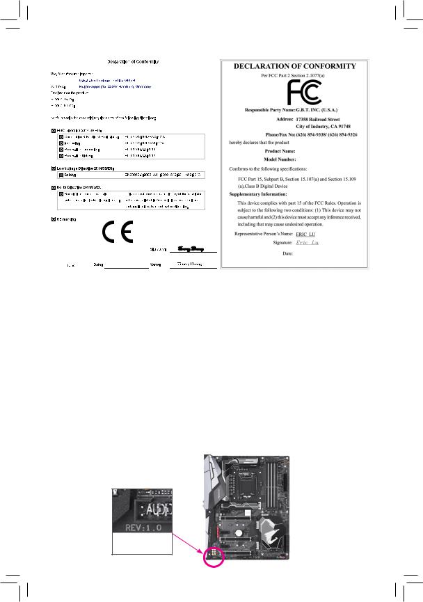
Motherboard
Z390 AORUS PRO
Aug. 31, 2018
Motherboard
Z390 AORUS PRO
Aug. 31, 2018
Copyright
© 2018 GIGA-BYTE TECHNOLOGY CO., LTD. All rights reserved.
The trademarks mentioned in this manual are legally registered to their respective owners.
Disclaimer
Information in this manual is protected by copyright laws and is the property of GIGABYTE.
ChangestothespecificationsandfeaturesinthismanualmaybemadebyGIGABYTEwithoutpriornotice.
No part of this manual may be reproduced, copied, translated, transmitted, or published in any form or by any means without GIGABYTE’s prior written permission.
In order to assist in the use of this product, carefully read the User’s Manual.
For product-related information, check on our website at: https://www.gigabyte.com
Identifying Your Motherboard Revision
The revision number on your motherboard looks like this: «REV: X.X.» For example, «REV: 1.0» means the revision of the motherboard is 1.0. Check your motherboard revision before updating motherboard BIOS, drivers, or when looking for technical information.
Example:

Table of Contents
|
Z390 AORUS PRO (WIFI) Motherboard Layout…………………………………………………….. |
5 |
|
|
Chapter 1 Hardware Installation………………………………………………………………………….. |
6 |
|
|
1-1 |
Installation Precautions…………………………………………………………………………. |
6 |
|
1-2 |
Product Specifications………………………………………………………………………….. |
7 |
|
1-3 |
Installing the CPU………………………………………………………………………………. |
11 |
|
1-4 |
Installing the Memory………………………………………………………………………….. |
11 |
|
1-5 Installing an Expansion Card……………………………………………………………….. |
12 |
|
|
1-6 Setting up AMD CrossFire™/NVIDIA® SLI™ Configuration…………………………. |
12 |
|
|
1-7 |
Back Panel Connectors………………………………………………………………………. |
13 |
|
1-8 |
Internal Connectors……………………………………………………………………………. |
15 |
|
Chapter 2 BIOS Setup……………………………………………………………………………………… |
25 |
|
|
2-1 |
Startup Screen…………………………………………………………………………………… |
25 |
|
2-2 |
The Main Menu………………………………………………………………………………….. |
26 |
|
2-3 |
M.I.T…………………………………………………………………………………………………. |
27 |
|
2-4 |
System……………………………………………………………………………………………… |
33 |
|
2-5 |
BIOS………………………………………………………………………………………………… |
34 |
|
2-6 |
Peripherals………………………………………………………………………………………… |
37 |
|
2-7 |
Chipset……………………………………………………………………………………………… |
40 |
|
2-8 |
Power……………………………………………………………………………………………….. |
41 |
|
2-9 |
Save & Exit……………………………………………………………………………………….. |
43 |
|
Chapter 3 Appendix…………………………………………………………………………………………. |
44 |
|
|
3-1 Configuring a RAID Set………………………………………………………………………. |
44 |
|
|
3-2 Installing an Intel® Optane™ Memory…………………………………………………….. |
46 |
|
|
3-3 |
Drivers Installation……………………………………………………………………………… |
48 |
|
Regulatory Statements…………………………………………………………………………………. |
49 |
|
|
Contact Us………………………………………………………………………………………………….. |
56 |
— 4 —
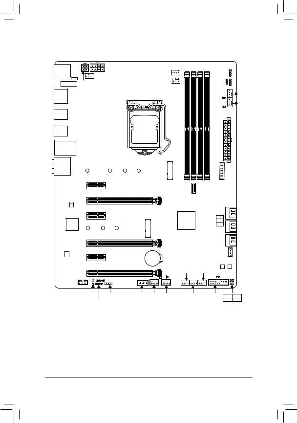
Z390 AORUS PRO (WIFI) Motherboard Layout
|
R_USB1 USB 2.0 |
ATX_12V_2X4 |
|||||
|
Hub(Note 2) |
SYS_FAN1 |
|||||
|
CNVI (Note 1) |
ATX_12V_2X2 |
|||||
|
WIFI MODULE (Note 1) |
||||||
|
HDMI |
LGA1151 |
|||||
|
R USB30 |
||||||
|
TYPEC |
||||||
|
USB31 |
||||||
|
USB30_LAN |
||||||
|
AUDIO |
110 |
80 |
60 |
42 |
||
|
PCIEX1_1 |
||||||
|
PCIEX16 |
Z390 AORUS PRO (WIFI) |
|||||
|
Intel® GbE |
||||||
|
LAN |
||||||
|
PCIEX1_2 |
||||||
|
iTE® |
80 |
60 |
42 |
M2M |
||
|
Super I/O |
||||||
PCIEX8
|
CPU_FAN |
SW2 LED2D |
||
|
V |
LED C2 |
FAN5SYS_ PUMP |
|
|
CPU_OPT |
DLED |
||
|
EC_TEMP1 |
|||
|
EC_TEMP2 |
_ |
||
|
SYSFAN6 PUMP |
|||
|
ATX |
|||
|
M2A DDR4 B1 DDR4 B2 |
F USB30 |
|
USB30C |
DDR4 A1 DDR4 A2 |
|
F |
|
|
1 0 |
|
|
Intel® Z390 |
3 2 |
|
5 4 |
|
|
SATA3 |
|
CODEC |
PCIEX1_3 |
||
|
BAT |
|||
|
PCIEX4 |
|||
|
F_AUDIO |
DLED_V_SW1 |
USB |
|
|
Box Contents |
SPDIF_O LED_C1 |
TPM F_USB2 F_USB1 |
|
|
D_LED1 |
|
THB C |
|||
|
M_BIOS |
|||
|
B_BIOS |
|||
|
SYS_FAN2 SYS_FAN4 |
CLR_CMOS |
||
|
2.0 Hub |
|||
|
SYS_FAN3 |
F_PANEL CPU |
DRAM |
|
|
VGA |
BOOT |
|
55 |
Z390 AORUS PRO or Z390 AORUS PRO WIFI motherboard |
||
|
55 |
Motherboard driver disk |
55 |
One digital LED strip adapter cable |
|
55 |
User’s Manual |
55 |
One RGB LED strip extension cable |
|
55 |
Quick Installation Guide |
55 |
One Wi-Fi antenna (Note 1) |
|
55 |
Four SATA cables |
55 |
One G Connector |
|
55 |
M.2 screw(s)/M.2 standoff(s) |
55 |
Two thermistor cables |
*The box contents above are for reference only and the actual items shall depend on the product package you obtain. The box contents are subject to change without notice.
(Note 1) Only for the Z390 AORUS PRO WIFI. (Note 2) The chip is on the back of the motherboard.
— 5 —

Chapter 1 Hardware Installation
1-1 Installation Precautions
The motherboard contains numerous delicate electronic circuits and components which can become damaged as a result of electrostatic discharge (ESD). Prior to installation, carefully read the user’s manual and follow these procedures:
•• Prior to installation, make sure the chassis is suitable for the motherboard.
•• Prior to installation, do not remove or break motherboard S/N (Serial Number) sticker or warranty sticker provided by your dealer. These stickers are required for warranty validation.
•• Always remove the AC power by unplugging the power cord from the power outlet before installing or removing the motherboard or other hardware components.
•• When connecting hardware components to the internal connectors on the motherboard, make sure they are connected tightly and securely.
•• When handling the motherboard, avoid touching any metal leads or connectors.
•• It is best to wear an electrostatic discharge (ESD) wrist strap when handling electronic components such as a motherboard, CPU or memory. If you do not have an ESD wrist strap, keep your hands dry and first touch a metal object to eliminate static electricity.
•• Prior to installing the motherboard, please have it on top of an antistatic pad or within an electrostatic shielding container.
•• Before connecting or unplugging the power supply cable from the motherboard, make sure the power supply has been turned off.
•• Before turning on the power, make sure the power supply voltage has been set according to the local voltage standard.
•• Before using the product, please verify that all cables and power connectors of your hardware components are connected.
•• To prevent damage to the motherboard, do not allow screws to come in contact with the motherboard circuit or its components.
•• Make sure there are no leftover screws or metal components placed on the motherboard or within the computer casing.
•• Do not place the computer system on an uneven surface.
•• Do not place the computer system in a high-temperature or wet environment.
•• Turning on the computer power during the installation process can lead to damage to system components as well as physical harm to the user.
•• If you are uncertain about any installation steps or have a problem related to the use of the product, please consult a certified computer technician.
•• If you use an adapter, extension power cable, or power strip, ensure to consult with its installation and/or grounding instructions.
— 6 —

|
1-2 |
Product Specifications |
|||
|
CPU |
Support for Intel 9000 Processors and 8th Generation Intel® Core™ i7 processors/ |
|||
|
Intel® Core™ i5 processors/Intel® Core™ i3 processors/Intel® Pentium® processors/ |
||||
|
Intel® Celeron® processors in the LGA1151 package |
||||
|
(Go to GIGABYTE’s website for the latest CPU support list.) |
||||
|
L3 cache varies with CPU |
||||
|
Chipset |
Intel® Z390 Express Chipset |
|||
|
Memory |
4 x DDR4 DIMM sockets supporting up to 64 GB of system memory |
|||
|
Dual channel memory architecture |
||||
|
Support for DDR4 2666/2400/2133 MHz memory modules |
||||
|
Support for ECC Un-buffered DIMM 1Rx8/2Rx8 memory modules (operate in |
||||
|
non-ECC mode) |
||||
|
Support for non-ECC Un-buffered DIMM 1Rx8/2Rx8/1Rx16 memory modules |
||||
|
Support for Extreme Memory Profile (XMP) memory modules |
||||
|
(Go to GIGABYTE’s website for the latest supported memory speeds and memory |
||||
|
modules.) |
||||
|
Onboard |
Integrated Graphics Processor-Intel® HD Graphics support: |
|||
|
Graphics |
— |
1 x HDMI port, supporting a maximum resolution of 4096×2160@30 Hz |
||
|
* Support for HDMI 1.4 version and HDCP 2.2. |
||||
|
Maximum shared memory of 1 GB |
||||
|
Audio |
Realtek® ALC1220-VB codec |
|||
|
* The back panel line out jack supports DSD audio. |
||||
|
High Definition Audio |
||||
|
2/4/5.1/7.1-channel |
||||
|
Support for S/PDIF Out |
||||
|
LAN |
Intel® GbE LAN chip (10/100/1000 Mbit) |
|||
|
Wireless |
Intel® CNVi interface 802.11a/b/g/n/ac, supporting 2.4/5 GHz Dual-Band |
|||
|
Communication |
BLUETOOTH 5 |
|||
|
Module (Note) |
Support for 11ac 160 MHz wireless standard and up to 1.73 Gbps data rate |
|||
|
* Actual data rate may vary depending on environment and equipment. |
||||
|
Expansion Slots |
1 x PCI Express x16 slot, running at x16 (PCIEX16) |
|||
|
* For optimum performance, if only one PCI Express graphics card is to be installed, |
||||
|
be sure to install it in the PCIEX16 slot. |
||||
|
1 x PCI Express x16 slot, running at x8 (PCIEX8) |
||||
|
* The PCIEX8 slot shares bandwidth with the PCIEX16 slot. When the PCIEX8 slot is |
||||
|
populated, the PCIEX16 slot operates at up to x8 mode. |
||||
|
1 x PCI Express x16 slot, running at x4 (PCIEX4) |
||||
|
3 x PCI Express x1 slots |
||||
|
(All of the PCI Express slots conform to PCI Express 3.0 standard.) |
||||
|
1 x M.2 Socket 1 connector for an Intel® CNVi wireless module (CNVI) (Note) |
||||
|
Multi-Graphics |
Support for NVIDIA® Quad-GPU SLI™ and 2-Way NVIDIA® SLI™ technologies |
|||
|
Technology |
Support for AMD Quad-GPU CrossFire™ and 3-Way/2-Way AMD CrossFire™ |
|||
|
technologies |
||||
|
(Note) |
Only for the Z390 AORUS PRO WIFI. |
|||
|
— 7 — |

|
Storage Interface |
Chipset: |
||
|
— |
1 x M.2 connector (Socket 3, M key, type 2242/2260/2280/22110 SATA and |
||
|
PCIe x4/x2 SSD support) (M2A) |
|||
|
— |
1 x M.2 connector (Socket 3, M key, type 2242/2260/2280 SATA and PCIe |
||
|
x4/x2 SSD support, prepared for Intel® Hybrid SSD) (M2M) |
|||
|
— |
6 x SATA 6Gb/s connectors |
||
|
— |
Support for RAID 0, RAID 1, RAID 5, and RAID 10 |
||
|
* Refer to «1-8 Internal Connectors,» for the installation notices for the M.2 and SATA |
|||
|
connectors. |
|||
|
Intel® Optane™ Memory Ready |
|||
|
USB |
Chipset: |
||
|
— |
1 x USB Type-C™ port with USB 3.1 Gen 2 support on the back panel |
||
|
— |
1 x USB Type-C™ port with USB 3.1 Gen 1 support, available through the |
||
|
internal USB header |
|||
|
— |
2 x USB 3.1 Gen 2 Type-A ports (red) on the back panel |
||
|
— |
5 x USB 3.1 Gen 1 ports (3 ports on the back panel, 2 ports available through |
||
|
the internal USB header) |
|||
|
Chipset+USB 2.0 Hub: |
|||
|
— |
8 x USB 2.0/1.1 ports (4 ports on the back panel, 4 ports available through |
||
|
the internal USB headers) |
|||
|
Internal |
1 x 24-pin ATX main power connector |
||
|
Connectors |
1 x 8-pin ATX 12V power connector |
1 x 4-pin ATX 12V power connector
1 x CPU fan header
1 x water cooling CPU fan header
4 x system fan headers
2 x system fan/water cooling pump headers
2 x digital LED strip headers
2 x digital LED strip power select jumpers
2 x RGB LED strip headers
6 x SATA 6Gb/s connectors
2 x M.2 Socket 3 connectors
1 x front panel header
1 x front panel audio header
1 x S/PDIF Out header
1 x USB Type-C™ port, with USB 3.1 Gen 1 support
1 x USB 3.1 Gen 1 header
2 x USB 2.0/1.1 headers
1 x Thunderbolt™ add-in card connector
1 x Trusted Platform Module (TPM) header (2×6 pin, for the GC-TPM2.0_S module only)
1 x Clear CMOS jumper
2 x temperature sensor headers
—8 —
|
Back Panel |
4 x USB 2.0/1.1 ports |
|
Connectors |
2 x SMA antenna connectors (2T2R) (Note) |
|
1 x HDMI port |
|
|
1 x USB Type-C™ port, with USB 3.1 Gen 2 support |
|
|
2 x USB 3.1 Gen 2 Type-A ports (red) |
|
|
3 x USB 3.1 Gen 1 ports |
|
|
1 x RJ-45 port |
|
|
1 x optical S/PDIF Out connector |
|
|
5 x audio jacks |
|
|
I/O Controller |
iTE® I/O Controller Chip |
Voltage detection
Temperature detection
Fan speed detection
Water cooling flow rate detection
Overheating warning
Fan fail warning
Fan speed control
*Whether the fan (pump) speed control function is supported will depend on the fan (pump) you install.
|
BIOS |
2 x 128 Mbit flash |
|
|
Use of licensed AMI UEFI BIOS |
Support for DualBIOS™
PnP 1.0a, DMI 2.7, WfM 2.0, SM BIOS 2.7, ACPI 5.0
Unique Features Support for APP Center
*Available applications in APP Center may vary by motherboard model. Supported functions of each application may also vary depending on motherboard specifications.
—3D OSD
—@BIOS
—AutoGreen
—Cloud Station
—EasyTune
—Easy RAID
—Fast Boot
—Game Boost
—ON/OFF Charge
—Platform Power Management
—RGB Fusion
(Note) Only for the Z390 AORUS PRO WIFI.
— 9 —
|
Unique Features |
— |
Smart Backup |
||
|
— |
Smart Keyboard |
|||
|
— |
Smart TimeLock |
|||
|
— |
Smart HUD |
|||
|
— |
System Information Viewer |
|||
|
— |
Smart Survey |
|||
|
— |
USB Blocker |
|||
|
Support for Q-Flash |
||||
|
Support for Xpress Install |
||||
|
Bundled |
Norton® Internet Security (OEM version) |
|||
|
Software |
cFosSpeed |
|||
|
Operating |
Support for Windows 10 64-bit |
|||
|
System |
||||
|
Form Factor |
ATX Form Factor; 30.5cm x 24.4cm |
*GIGABYTE reserves the right to make any changes to the product specifications and product-related information without prior notice.
|
Z390 AORUS PRO |
Z390 AORUS PRO |
|
WIFI |
Please visit GIGABYTE’s website for support lists of CPU, memory modules, SSDs, and M.2 devices.
Please visit the SupportUtility List page on GIGABYTE’s website to download the latest version of apps.
— 10 —
![]()
|
1-3 |
Installing the CPU |
|
|
Read the following guidelines before you begin to install the CPU: |
||
|
•• |
Make sure that the motherboard supports the CPU. |
|
|
(Go to GIGABYTE’s website for the latest CPU support list.) |
||
|
•• |
Always turn off the computer and unplug the power cord from the power outlet before installing the |
|
|
•• |
CPU to prevent hardware damage. |
|
|
Locate the pin one of the CPU. The CPU cannot be inserted if oriented incorrectly. (Or you may |
||
|
•• |
locate the notches on both sides of the CPU and alignment keys on the CPU socket.) |
|
|
Apply an even and thin layer of thermal grease on the surface of the CPU. |
||
|
•• |
Do not turn on the computer if the CPU cooler is not installed, otherwise overheating and damage |
|
|
•• |
of the CPU may occur. |
|
|
Set the CPU host frequency in accordance with the CPU specifications. It is not recommended |
||
|
that the system bus frequency be set beyond hardware specifications since it does not meet the |
||
|
standard requirements for the peripherals. If you wish to set the frequency beyond the standard |
||
|
specifications, please do so according to your hardware specifications including the CPU, graphics |
||
|
card, memory, hard drive, etc. |
Installing the CPU
Locate the alignment keys on the motherboard CPU socket and the notches on the CPU.
|
LGA1151 CPU Socket |
LGA1151 CPU |
||
|
Alignment Key |
Alignment Key |
Notch |
Notch |
|
Pin One Corner of the CPU Socket |
Triangle Pin One Marking on the CPU |
Do not remove the CPU socket cover before inserting the CPU. It may pop off from the load plate automatically during the process of re-engaging the lever after you insert the CPU.
1-4 Installing the Memory
Read the following guidelines before you begin to install the memory:
•• Make sure that the motherboard supports the memory. It is recommended that memory of the same capacity, brand, speed, and chips be used.
(Go to GIGABYTE’s website for the latest supported memory speeds and memory modules.)
•• Always turn off the computer and unplug the power cord from the power outlet before installing the memory to prevent hardware damage.
•• Memory modules have a foolproof design. A memory module can be installed in only one direction. If you are unable to insert the memory, switch the direction.
Dual Channel Memory Configuration
This motherboard provides four memory sockets and supports Dual Channel Technology. After the memory is installed, the BIOS will automatically detect the specifications and capacity of the memory. Enabling Dual
Channel memory mode will double the original memory bandwidth.
The four memory sockets are divided into two channels and each channel has two memory sockets as following:
Please visit GIGABYTE’s website for details on hardware installation.
— 11 —
Channel A: DDR4_A1, DDR4_A2Channel B: DDR4_B1, DDR4_B2
Dual Channel Memory Configurations Table
|
DDR4_B1 |
DDR4_B2 |
DDR4_A1 |
DDR4_A2 |
|
|
2 Modules |
— — |
DS/SS |
— — |
DS/SS |
|
DS/SS |
— — |
DS/SS |
— — |
|
|
4 Modules |
DS/SS |
DS/SS |
DS/SS |
DS/SS |
(SS=Single-Sided, DS=Double-Sided, «- -«=No Memory)
Due to CPU limitations, read the following guidelines before installing the memory in Dual Channel mode.
1.Dual Channel mode cannot be enabled if only one memory module is installed.
2.When enabling Dual Channel mode with two or four memory modules, it is recommended that memory of the same capacity, brand, speed, and chips be used.
1-5 Installing an Expansion Card
Read the following guidelines before you begin to install an expansion card:
•• Make sure the motherboard supports the expansion card. Carefully read the manual that came with your expansion card.
•• Always turn off the computer and unplug the power cord from the power outlet before installing an expansion card to prevent hardware damage.
1-6 Setting up AMD CrossFire™/NVIDIA® SLI™ Configuration
A.System Requirements
— Windows 10 64-bit operating system
— A CrossFire/SLI-supported motherboard with two or more PCI Express x16 slots and correct driver — CrossFire/SLI-ready graphics cards of identical brand and chip and correct driver
(For the latest GPUs that support the 3-way CrossFire technology, please refer to the AMD website.) (Note 1) — CrossFire (Note 2)/SLI bridge connectors
— A power supply with sufficient power is recommended (Refer to the manual of your graphics cards for the power requirement)
B.Connecting the Graphics Cards
Step 1:
Observe the steps in «1-5 Installing an Expansion Card» and install CrossFire/SLI graphics cards on the PCI
Express x16 slots. (To set up a 2-Way configuration, we recommend installing the graphics cards on the
PCIEX16 and PCIEX8 slots.) Step 2:
Insert the CrossFire (Note 2)/SLI bridge connectors in the CrossFire/SLI gold edge connectors on top of the cards. Step 3:
Plug the display cable into the graphics card on the PCIEX16 slot.
C. Configuring the Graphics Card Driver
C-1. To Enable CrossFire Function
After installing the graphics card driver in the operating system, go to the AMD RADEON SETTINGS screen. Browse to GamingGlobal Settings and ensure AMD CrossFire is set to On.
C-2. To Enable SLI Function
After installing the graphics card driver in the operating system, go to the NVIDIA Control Panel. Browse to the
Configure SLI, Surround, Physx screen and ensure Maximize 3D performance is enabled.
(Note 1) When using dual core graphics cards, only 2-way is supported.
(Note 2) The bridge connector(s) may be needed or not depending on your graphics cards.
Procedure and driver screen for enabling CrossFire/SLI technology may differ by graphics cards and driver version. Refer to the manual that came with your graphics cards for more information about enabling CrossFire/SLI technology.
— 12 —
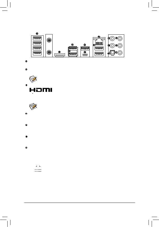
1-7 Back Panel Connectors
 (Note)
USB 2.0/1.1 Port
The USB port supports the USB 2.0/1.1 specification. Use this port for USB devices.
SMA Antenna Connectors (2T2R) (Note)
Use this connector to connect an antenna.

 Tighten the antenna cables to the antenna connectors and then move the antenna to a place
where the signal is good.
HDMI Port
 The HDMI port supports HDCP 2.2 and Dolby TrueHD and DTS HD Master Audio


 formats. It also supports up to 192KHz/16bit 8-channel LPCM audio output. You can use this port to connect your HDMI-supported monitor. The maximum supported resolution is 4096×2160@30 Hz, but the actual resolutions supported are dependent on the monitor being used.
After installing the HDMI device, make sure to set the default sound playback device to HDMI. (The item name may differ depending on your operating system.)
USB 3.1 Gen 1 Port
The USB 3.1 Gen 1 port supports the USB 3.1 Gen 1 specification and is compatible to the USB 2.0 specification. Use this port for USB devices.
USB 3.1 Gen 2 Type-A Port (Red)
The USB 3.1 Gen 2 Type-A port supports the USB 3.1 Gen 2 specification and is compatible to the USB 3.1 Gen 1 and USB 2.0 specification. Use this port for USB devices.
USB Type-C™ Port
The reversible USB port supports the USB 3.1 Gen 2 specification and is compatible to the USB 3.1 Gen 1 and USB 2.0 specification. Use this port for USB devices.
RJ-45 LAN Port
The Gigabit Ethernet LAN port provides Internet connection at up to 1 Gbps data rate. The following describes the states of the LAN port LEDs.
|
Connection/ |
Connection/Speed LED: |
Activity LED: |
|||||||||||||||||
|
Speed LED |
Activity LED |
||||||||||||||||||
|
State |
Description |
State |
Description |
||||||||||||||||
|
Orange |
1 Gbps data rate |
Blinking |
Data transmission or receiving is occurring |
||||||||||||||||
|
Green |
100 Mbps data rate |
On |
No data transmission or receiving is occurring |
||||||||||||||||
|
Off |
10 Mbps data rate |
||||||||||||||||||
|
LAN Port |
|||||||||||||||||||
(Note) Only for the Z390 AORUS PRO WIFI.
— 13 —
Center/Subwoofer Speaker Out
Use this audio jack to connect center/subwoofer speakers.
Rear Speaker Out
Use this audio jack to connect rear speakers.
Optical S/PDIF Out Connector
This connector provides digital audio out to an external audio system that supports digital optical audio. Before using this feature, ensure that your audio system provides an optical digital audio in connector.
Line In/Side Speaker Out
The line in jack. Use this audio jack for line in devices such as an optical drive, walkman, etc.
Line Out/Front Speaker Out
The line out jack. This jack supports audio amplifying function. For better sound quality, it is recommended that you connect your headphone/speaker to this jack (actual effects may vary by the device being used).
Mic In/Side Speaker Out
The Mic in jack.
Audio Jack Configurations:
|
Jack |
Headphone/ |
4-channel |
5.1-channel |
7.1-channel |
|
|
2-channel |
|||||
|
Center/Subwoofer Speaker Out |
a |
a |
|||
|
Rear Speaker Out |
a |
a |
a |
||
|
Line In/Side Speaker Out |
a |
||||
|
Line Out/Front Speaker Out |
a |
a |
a |
a |
|
|
Mic In/Side Speaker Out |
a |
||||

 If you want to install a Side Speaker, you need to retask either the Line in or Mic in jack to be Side Speaker out through the audio driver.
•• When removing the cable connected to a back panel connector, first remove the cable from your device and then remove it from the motherboard.
•• When removing the cable, pull it straight out from the connector. Do not rock it side to side to prevent an electrical short inside the cable connector.
Please visit GIGABYTE’s website for details on configuring the audio software.
— 14 —
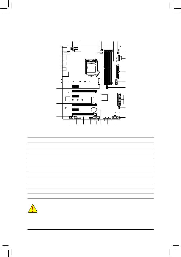
|
1-8 |
Internal Connectors |
|||||||||
|
1 |
1 |
4 |
6 |
3 |
7 |
10 |
||||
|
9 |
||||||||||
|
8 |
||||||||||
|
5 |
||||||||||
|
2 |
||||||||||
|
17 |
||||||||||
|
12 |
16 |
|||||||||
|
11 |
||||||||||
|
12 |
||||||||||
|
20 |
||||||||||
|
15 |
21 |
|||||||||
|
23 |
||||||||||
|
14 |
9 |
8 |
10 |
19 |
18 |
22 |
4 |
13 |
||
|
1) |
ATX_12V_2X2/ATX_12V_2X4 |
13) |
F_PANEL |
|||||||
|
2) |
ATX |
14) |
F_AUDIO |
|||||||
|
3) |
CPU_FAN |
15) |
SPDIF_O |
|||||||
|
4) |
SYS_FAN1/2/3/4 |
16) |
F_USB30C |
|||||||
|
5) |
SYS_FAN5/6_PUMP |
17) |
F_USB30 |
|||||||
|
6) |
CPU_OPT |
18) |
F_USB1/F_USB2 |
|||||||
|
7) |
EC_TEMP1/EC_TEMP2 |
19) |
TPM |
|||||||
|
|
LED_C1/LED_C2 |
20) |
THB_C |
|||||||
|
9) |
D_LED1/D_LED2 |
21) |
CLR_CMOS |
|||||||
|
10) |
DLED_V_SW1/DLED_V_SW2 |
22) |
BAT |
|||||||
|
11) |
SATA3 0/1/2/3/4/5 |
23) |
CPU/DRAM/VGA/BOOT |
|||||||
|
12) |
M2A/M2M |
Read the following guidelines before connecting external devices:
•• First make sure your devices are compliant with the connectors you wish to connect.
•• Before installing the devices, be sure to turn off the devices and your computer. Unplug the power cord from the power outlet to prevent damage to the devices.
•• After installing the device and before turning on the computer, make sure the device cable has been securely attached to the connector on the motherboard.
— 15 —
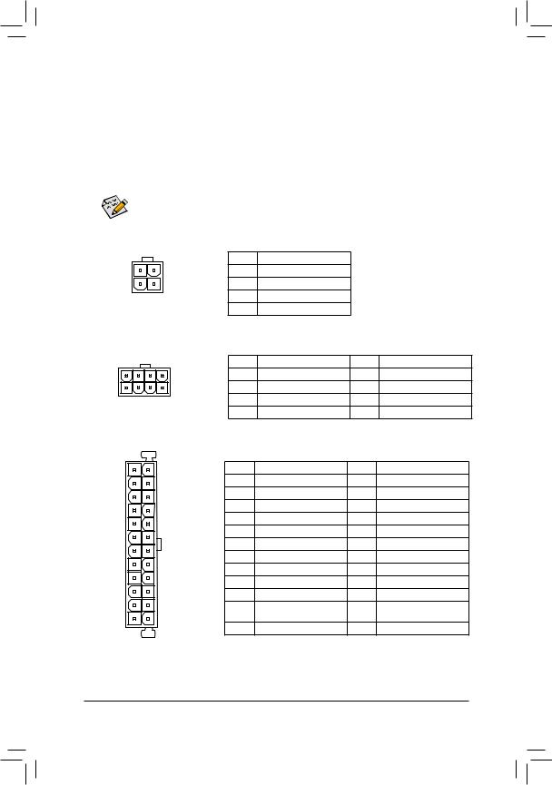
1/2)ATX_12V_2X2/ATX_12V_2X4/ATX (2×2, 2×4, 12V Power Connectors and 2×12 Main
Power Connector)
With the use of the power connector, the power supply can supply enough stable power to all the components on the motherboard. Before connecting the power connector, first make sure the power supply is turned off and all devices are properly installed. The power connector possesses a foolproof design. Connect the power supply cable to the power connector in the correct orientation.
The 12V power connector mainly supplies power to the CPU. If the 12V power connector is not connected, the computer will not start.
To meet expansion requirements, it is recommended that a power supply that can withstand high power consumption be used (500W or greater). If a power supply is used that does not provide the required power, the result can lead to an unstable or unbootable system.
|
ATX_12V_2X2: |
||||||
|
Pin No. |
Definition |
|||||
|
3 |
4 |
1 |
GND |
|||
|
1 |
2 |
2 |
GND |
|||
|
ATX_12V_2X2 |
3 |
+12V |
||||
|
4 |
+12V |
|||||
|
ATX_12V_2X4: |
||||||
|
Pin No. |
Definition |
Pin No. |
Definition |
|||
|
5 |
8 |
1 |
GND (Only for 2×4-pin 12V) |
5 |
+12V (Only for 2×4-pin 12V) |
|
|
1 |
4 |
2 |
GND (Only for 2×4-pin 12V) |
6 |
+12V (Only for 2×4-pin 12V) |
|
|
ATX_12V_2X4 |
3 |
GND |
7 |
+12V |
||
|
4 |
GND |
8 |
+12V |
|||
|
ATX: |
||||||
|
12 |
24 |
Pin No. |
Definition |
Pin No. |
Definition |
|
|
1 |
3.3V |
13 |
3.3V |
|||
|
2 |
3.3V |
14 |
-12V |
|||
|
3 |
GND |
15 |
GND |
|||
|
4 |
+5V |
16 |
PS_ON (soft On/Off) |
|||
|
5 |
GND |
17 |
GND |
|||
|
6 |
+5V |
18 |
GND |
|||
|
7 |
GND |
19 |
GND |
|||
|
8 |
Power Good |
20 |
NC |
|||
|
9 |
5VSB (stand by +5V) |
21 |
+5V |
|||
|
10 |
+12V |
22 |
+5V |
|||
|
11 |
+12V (Only for 2×12-pin |
23 |
+5V (Only for 2×12-pin ATX) |
|||
|
1 |
13 |
12 |
ATX) |
24 |
GND (Only for 2×12-pin ATX) |
|
|
3.3V (Only for 2×12-pin ATX) |
ATX
— 16 —
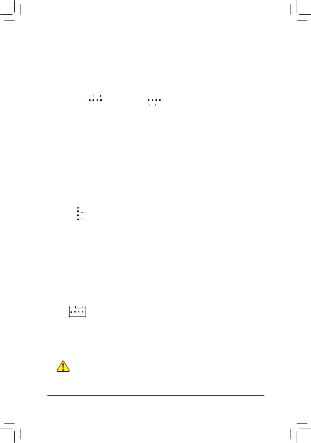
3/4) CPU_FAN/SYS_FAN1/2/3/4 (Fan Headers)
All fan headers on this motherboard are 4-pin. Most fan headers possess a foolproof insertion design. When connecting a fan cable, be sure to connect it in the correct orientation (the black connector wire is the ground wire). The speed control function requires the use of a fan with fan speed control design. For optimum heat dissipation, it is recommended that a system fan be installed inside the chassis.
|
Pin No. |
Definition |
||||||||||
|
1 |
1 |
1 |
GND |
||||||||
|
2 |
Voltage Speed Control |
||||||||||
|
CPU_FAN/SYS_FAN1 |
SYS_FAN2/SYS_FAN3/SYS_FAN4 |
3 |
Sense |
||||||||
|
4 |
PWM Speed Control |
5)SYS_FAN5/6_PUMP (System Fan/Water Cooling Pump Headers)
The fan/pump headers are 4-pin and possess a foolproof insertion design. Most fan headers possess a foolproof insertion design. When connecting a fan cable, be sure to connect it in the correct orientation (the black connector wire is the ground wire). The speed control function requires the use of a fan with fan speed control design. For optimum heat dissipation, it is recommended that a system fan be installed inside the chassis. The header also provides speed control for a water cooling pump, refer to Chapter 2, «BIOS Setup,» «M.I.T.,» for more information.
|
Pin No. |
Definition |
||
|
1 |
GND |
||
|
2 |
Voltage Speed Control |
||
|
1 |
3 |
Sense |
|
|
4 |
PWM Speed Control |
6)CPU_OPT (Water Cooling CPU Fan Header)
The fan header is 4-pin and possesses a foolproof insertion design. Most fan headers possess a foolproof insertion design. When connecting a fan cable, be sure to connect it in the correct orientation (the black connector wire is the ground wire). The speed control function requires the use of a fan with fan speed control design.
|
Pin No. |
Definition |
|
|
1 |
1 |
GND |
|
2 |
Voltage Speed Control |
|
|
3 |
Sense |
|
|
4 |
PWM Speed Control |
•• Be sure to connect fan cables to the fan headers to prevent your CPU and system from overheating. Overheating may result in damage to the CPU or the system may hang.
•• Thesefanheadersarenotconfigurationjumperblocks.Donotplaceajumpercapontheheaders.
— 17 —
 Loading…