- Manuals
- Brands
- Gigabyte Manuals
- Motherboard
- Z390 GAMING X
- User manual
-
Contents
-
Table of Contents
-
Bookmarks
Quick Links
Z390 GAMING X
User’s Manual
Rev. 1001
12ME-Z39GX-1001R
For more product details, please visit GIGABYTE’s website.
To reduce the impacts on global warming, the packaging materials of this product
are recyclable and reusable. GIGABYTE works with you to protect the environment.
Related Manuals for Gigabyte Z390 GAMING X
Summary of Contents for Gigabyte Z390 GAMING X
-
Page 1
Z390 GAMING X User’s Manual Rev. 1001 12ME-Z39GX-1001R For more product details, please visit GIGABYTE’s website. To reduce the impacts on global warming, the packaging materials of this product are recyclable and reusable. GIGABYTE works with you to protect the environment. -
Page 2
Information in this manual is protected by copyright laws and is the property of GIGABYTE. Changes to the specifications and features in this manual may be made by GIGABYTE without prior notice. No part of this manual may be reproduced, copied, translated, transmitted, or published in any form or by any means without GIGABYTE’s prior written permission. -
Page 3: Table Of Contents
Table of Contents Z390 GAMING X Motherboard Layout …………….4 Chapter 1 Hardware Installation ………………5 Installation Precautions ………………5 1-2 Product Specifications ………………6 Installing the CPU ……………….. 9 Installing the Memory ………………9 Installing an Expansion Card …………….. 10 Back Panel Connectors ……………… 10 Internal Connectors ………………
-
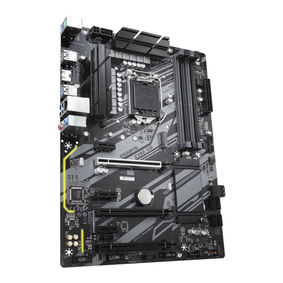
Page 4: Z390 Gaming X Motherboard Layout
Z390 GAMING X Motherboard Layout ATX_12V_2X4 KB_MS_USB CPU_FAN SYS_FAN1 ATX_12V_2X2 LGA1151 R_USB30 R_USB31 USB30_LAN AUDIO PCIEX1_1 Z390 GAMING X PCIEX16 Intel ® Intel Z390 PCIEX1_2 ® ® Super I/O PCIEX4 CODEC PCIEX1_3 B_BIOS THB_C M_BIOS PCIEX1_4 CLR_CMOS F_AUDIO F_USB LED_C…
-
Page 5: Chapter 1 Hardware Installation
Chapter 1 Hardware Installation Installation Precautions The motherboard contains numerous delicate electronic circuits and components which can become damaged as a result of electrostatic discharge (ESD). Prior to installation, carefully read the user’s manual and follow these procedures: • Prior to installation, make sure the chassis is suitable for the motherboard. • Prior to installation, do not remove or break motherboard S/N (Serial Number) sticker or warranty sticker provided by your dealer.
-
Page 6: 1-2 Product Specifications
Š S upport for ECC Un-buffered DIMM 1Rx8/2Rx8 memory modules (operate in Š non-ECC mode) Support for non-ECC Un-buffered DIMM 1Rx8/2Rx8/1Rx16 memory modules Š Support for Extreme Memory Profile (XMP) memory modules Š (Go to GIGABYTE’s website for the latest supported memory speeds and memory modules.) Onboard Integrated Graphics Processor-Intel HD Graphics support: ® Š Graphics 1 x HDMI port, supporting a maximum resolution of 4096×2160@30 Hz * Support for HDMI 1.4 version and HDCP 2.2.
-
Page 7
Chipset: Š 1 x USB 3.1 Gen 2 Type-A port (red) on the back panel 7 x USB 3.1 Gen 1 ports (5 ports on the back panel, 2 ports available through the internal USB header) 4 x USB 2.0/1.1 ports (2 ports on the back panel, 2 ports available through the internal USB header) Internal 1 x 24-pin ATX main power connector… -
Page 8
ATX Form Factor; 30.5cm x 22.5cm Š * G IGABYTE reserves the right to make any changes to the product specifications and product-related information without prior notice. Please visit the SupportUtility List Please visit GIGABYTE’s website for support lists of CPU, memory page on GIGABYTE’s website to modules, SSDs, and M.2 devices. download the latest version of apps. — 8 -… -
Page 9: Installing The Cpu
• Make sure that the motherboard supports the memory. It is recommended that memory of the same capacity, brand, speed, and chips be used. (Go to GIGABYTE’s website for the latest supported memory speeds and memory modules.) • Always turn off the computer and unplug the power cord from the power outlet before installing the memory to prevent hardware damage.
-
Page 10: Installing An Expansion Card
The four memory sockets are divided into two channels and each channel has two memory sockets as following: Channel A: DDR4_A1, DDR4_A2 Channel B: DDR4_B1, DDR4_B2 Dual Channel Memory Configurations Table DDR4_B1 DDR4_B2 DDR4_A1 DDR4_A2 2 Modules DS/SS DS/SS DS/SS DS/SS 4 Modules DS/SS DS/SS DS/SS DS/SS (SS=Single-Sided, DS=Double-Sided, «- -«=No Memory) Due to CPU limitations, read the following guidelines before installing the memory in Dual Channel mode. Dual Channel mode cannot be enabled if only one memory module is installed. When enabling Dual Channel mode with two or four memory modules, it is recommended that memory of the same capacity, brand, speed, and chips be used.
-
Page 11
2-channel Center/Subwoofer Speaker Out Rear Speaker Out Side Speaker Out Line In Line Out/Front Speaker Out Mic In • When removing the cable connected to a back panel connector, first remove the cable from your device and then remove it from the motherboard. • When removing the cable, pull it straight out from the connector. Do not rock it side to side to prevent an electrical short inside the cable connector. Please visit GIGABYTE’s website for details on configuring the audio software. — 11 -… -
Page 12: Internal Connectors
Internal Connectors 9 10 8 18 ATX_12V_2X2/ATX_12V_2X4 SPDIF_O F_USB30 CPU_FAN F_USB SYS_FAN1/2/3 THB_C LED_C SATA3 0/1/2/3/4/5 M2A/M2M CLR_CMOS F_PANEL F_AUDIO CPU/DRAM/VGA/BOOT Read the following guidelines before connecting external devices: • First make sure your devices are compliant with the connectors you wish to connect. • Before installing the devices, be sure to turn off the devices and your computer. Unplug the power cord from the power outlet to prevent damage to the devices.
-
Page 13
1/2) ATX_12V_2X2/ATX_12V_2X4/ATX (2×2, 2×4, 12V Power Connectors and 2×12 Main Power Connector) With the use of the power connector, the power supply can supply enough stable power to all the components on the motherboard. Before connecting the power connector, first make sure the power supply is turned off and The power connector possesses a foolproof design. Connect the power all devices are properly installed. -
Page 14
Pin No. Definition Connect your RGB LED strip to the header. The power pin (marked with a triangle on the plug) of the LED strip must be connected to Pin 1 (12V) of RGB this header. Incorrect connection may lead to the damage of the LED strip. LED Strip For how to turn on/off the lights of the LED strip please visit the «Unique Features» webpage of GIGABYTE’s website. Before installing the devices, be sure to turn off the devices and your computer. Unplug the power cord from the power outlet to prevent damage to the devices. — 14 -… -
Page 15
S B_ 6) SATA3 0/1/2/3/4/5 (SATA 6Gb/s Connectors) The SATA connectors conform to SATA 6Gb/s standard and are compatible with SATA 3Gb/s and SATA 1.5Gb/s standard. Each SATA connector supports a single SATA device. The Intel Chipset supports RAID 0, ® RAID 1, RAID 5, and RAID 10. Refer to Chapter 3, «Configuring a RAID Set,» for instructions on configuring a RAID array. Pin No. -
Page 16
Installation Notices for the M.2 and SATA Connectors: Due to the limited number of lanes provided by the Chipset, the availability of the SATA connectors may be affected by the type of device installed in the M.2 connector. The M2A connector shares bandwidth with the SATA3 1. The M2M connector shares bandwidth with the SATA3 4, 5 connectors. Refer to the following tables for details. • M2A: Connector Type of SATA3 0 SATA3 1 SATA3 2 SATA3 3 SATA3 4 SATA3 5… -
Page 17
 F_PANEL (Front Panel Header) Connect the power switch, reset switch, speaker, chassis intrusion switch/sensor and system status indicator on the chassis to this header according to the pin assignments below. Note the positive and negative pins before connecting the cables. •…
 -
Page 18
10) SPDIF_O (S/PDIF Out Header) This header supports digital S/PDIF Out and connects a S/PDIF digital audio cable (provided by expansion cards) for digital audio output from your motherboard to certain expansion cards like graphics cards and sound cards. For example, some graphics cards may require you to use a S/PDIF digital audio cable for digital audio output from your motherboard to your graphics card if you wish to connect an HDMI display to the graphics card and have digital audio output from the HDMI display at the same time. For information about connecting the S/PDIF digital audio cable, carefully read the manual for your expansion card. Pin No. Definition 5VDUAL S F_ No Pin SPDIFO F_USB30 F_ U 11) F_USB30 (USB 3.1 Gen 1 Header) The header conforms to USB 3.1 Gen 1 and USB 2.0 specification and can provide two USB ports. For purchasing the optional 3.5″ front panel that provides two USB 3.1 Gen 1 ports, please contact the local dealer. -
Page 19
13) THB_C (Thunderbolt Add-in Card Connector) ™ This connector is for a GIGABYTE Thunderbolt add-in card. ™ Supports a Thunderbolt add-in card. ™ B S_ S B_ 14) COM (Serial Port Header) The COM header can provide one serial port via an optional COM port cable. For purchasing the optional COM port cable, please contact the local dealer. -
Page 20
B S S 16) CLR_CMOS (Clear CMOS Jumper) Use this jumper to clear the BIOS configuration and reset the CMOS values to factory defaults. To clear the CMOS values, use a metal object like a screwdriver to touch the two pins for a few seconds. F_USB3 F Open: Normal Short: Clear CMOS Values • Always turn off your computer and unplug the power cord from the power outlet before clearing the CMOS values. -
Page 21: Chapter 2 Bios Setup
BIOS includes a BIOS Setup program that allows the user to modify basic system configuration settings or to activate certain system features. When the power is turned off, the battery on the motherboard supplies the necessary power to the CMOS to keep the configuration values in the CMOS. To access the BIOS Setup program, press the <Delete> key during the POST when the power is turned on. To upgrade the BIOS, use either the GIGABYTE Q-Flash or @BIOS utility. Q-Flash allows the user to quickly and easily upgrade or back up BIOS without entering the operating system. • @BIOS is a Windows-based utility that searches and downloads the latest version of BIOS from the Internet •…
-
Page 22: The Main Menu
The Main Menu System Time Setup Menus Hardware Information Configuration Items Current Settings Quick Access Bar allows you to enter Easy Mode, select BIOS default language, configure fan settings, or enter Q-Flash. Classic Setup Function Keys <f><g> Move the selection bar to select a setup menu <h><i> Move the selection bar to select an configuration item on a menu <Enter> Execute command or enter a menu <+>/<Page Up> Increase the numeric value or make changes <->/<Page Down>…
-
Page 23
M.I.T. Whether the system will work stably with the overclock/overvoltage settings you made is dependent on your overall system configurations. Incorrectly doing overclock/overvoltage may result in damage to CPU, chipset, or memory and reduce the useful life of these components. This page is for advanced users only and we recommend you not to alter the default settings to prevent system instability or other unexpected results. -
Page 24
& FCLK Frequency for Early Power On Allows you to set the FCLK frequency. Options are: Normal(800Mhz), 1GHz, 400MHz. (Default: 1GHz) ` Advanced CPU Core Settings & CPU Clock Ratio, CPU Frequency, FCLK Frequency for Early Power On The settings above are synchronous to those under the same items on the Advanced Frequency Settings menu. -
Page 25
& CPU Enhanced Halt (C1E) (Note) Enables or disables Intel CPU Enhanced Halt (C1E) function, a CPU power-saving function in system halt ® state. When enabled, the CPU core frequency and voltage will be reduced during system halt state to decrease power consumption. -
Page 26
& Adjacent Cache Line Prefetch Allows you to determine whether to enable the adjacent cache line prefetch mechanism that lets the processor retrieve the requested cache line as well as the subsequent cache line. (Default: Auto) & Extreme Memory Profile (X.M.P.) (Note) Allows the BIOS to read the SPD data on XMP memory module(s) to enhance memory performance when enabled. Disabled Disables this function. (Default) Uses Profile 1 settings. Profile1 Uses Profile 2 settings. (Note) Profile2 & System Memory Multiplier Allows you to set the system memory multiplier. Auto sets memory multiplier according to memory SPD data. (Default: Auto) &… -
Page 27
& Profile DDR Voltage When using a non-XMP memory module or Extreme Memory Profile (X.M.P.) is set to Disabled, the value is displayed according to your memory specification. When Extreme Memory Profile (X.M.P.) is set to Profile1 or Profile2, the value is displayed according to the SPD data on the XMP memory. & Memory Multiplier Tweaker Provides different levels of memory auto-tuning. (Default: Auto) & Channel Interleaving Enables or disables memory channel interleaving. Enabled allows the system to simultaneously access different channels of the memory to increase memory performance and stability. -
Page 28
& CPU Vcore/CPU VCCSA/DRAM Channel A/B Voltage/+3.3V/+5V/+12V/CPU VAXG Displays the current system voltages. ` Miscellaneous Settings & Max Link Speed Allows you to set the operation mode of the PCI Express slots to Gen 1, Gen 2, or Gen 3. Actual operation mode is subject to the hardware specification of each slot. Auto lets the BIOS automatically configure this setting. (Default: Auto) &… -
Page 29: System
System This section provides information on your motherboard model and BIOS version. You can also select the default language used by the BIOS and manually set the system time. & Access Level Displays the current access level depending on the type of password protection used. (If no password is set, the default will display as Administrator.) The Administrator level allows you to make changes to all BIOS settings;…
-
Page 30: Bios
A password is required for booting the system and for entering the BIOS Setup program. System (Default) & Full Screen LOGO Show Allows you to determine whether to display the GIGABYTE Logo at system startup. Disabled skips the GIGABYTE Logo when the system starts up. (Default: Enabled) & Boot Option Priorities Specifies the overall boot order from the available devices. Removable storage devices that support GPT format will be prefixed with «UEFI:» string on the boot device list. To boot from an operating system that…
-
Page 31
& SATA Support Last Boot HDD Only E xcept for the previous boot drive, all SATA devices are disabled before the OS boot process completes. (Default) All Sata Devices A ll SATA devices are functional in the operating system and during the POST. This item is configurable only when Fast Boot is set to Enabled or Ultra Fast. & VGA Support Allows you to select which type of operating system to boot. Auto Enables legacy option ROM only. EFI Driver Enables EFI option ROM. (Default) This item is configurable only when Fast Boot is set to Enabled or Ultra Fast. &… -
Page 32
& Other PCI devices Allows you to select whether to enable the UEFI or Legacy option ROM for the PCI device controller other than the LAN, storage device, and graphics controllers. Do not launch Disables option ROM. UEFI Enables UEFI option ROM only. (Default) Enables legacy option ROM only. Legacy This item is configurable only when CSM Support is set to Enabled. & Administrator Password Allows you to configure an administrator password. Press <Enter> on this item, type the password, and then press <Enter>. You will be requested to confirm the password. Type the password again and press <Enter>. You must enter the administrator password (or user password) at system startup and when entering BIOS Setup. Differing from the user password, the administrator password allows you to make changes to all BIOS settings. & User Password Allows you to configure a user password. Press <Enter> on this item, type the password, and then press <Enter>. You will be requested to confirm the password. Type the password again and press <Enter>. You must enter the administrator password (or user password) at system startup and when entering BIOS Setup. -
Page 33: Peripherals
Peripherals & PCIE Bifurcation Support Allows you to determine how the the bandwidth of the PCIEX16 slot is divided. Options: PCIE x16, PCIE x8/x8, PCIE x8/x4/x4. (Default: PCIE x16) & Initial Display Output Specifies the first initiation of the monitor display from the installed PCI Express graphics card or the onboard graphics. IGFX Sets the onboard graphics as the first display. Sets the graphics card on the PCIEX16 slot as the first display. (Default) PCIe 1 Slot Sets the graphics card on the PCIEX4 slot as the first display. PCIe 2 Slot & EZ RAID Allows you to quickly set up a RAID array. Refer to Chapter 3, «Configuring a RAID Set,» for instructions on configuring a RAID array.
-
Page 34
` Trusted Computing Enables or disables Trusted Platform Module (TPM). ` Super IO Configuration & Serial Port Enables or disables the onboard serial port. (Default: Enabled) ` Intel(R) Bios Guard Technology Enables or disables the Intel BIOS Guard feature, which protects the BIOS from malicious attacks. ® ` USB Configuration & Legacy USB Support Allows USB keyboard/mouse to be used in MS-DOS. (Default: Enabled) &… -
Page 35
& Media detect count Allows you to set the number of times to check the presence of media. This item is configurable only when Network Stack is enabled. (Default: 1) ` NVMe Configuration Displays information on your M.2 NVME PCIe SSD if installed. ` SATA And RST Configuration & SATA Controller(s) Enables or disables the integrated SATA controllers. (Default: Enabled) & SATA Mode Selection Enables or disables RAID for the SATA controllers integrated in the Chipset or configures the SATA controllers to AHCI mode. Enables RAID for the SATA controller. Intel RST Premium With Intel Optane System Acceleration AHCI C onfigures the SATA controllers to AHCI mode. Advanced Host Controller Interface (AHCI) is an interface specification that allows the storage driver to enable advanced Serial ATA features such as Native Command Queuing and hot plug. (Default) & Aggressive LPM Support Enables or disables the power saving feature, ALPM (Aggressive Link Power Management), for the Chipset SATA controllers. (Default: Enabled) &… -
Page 36: Chipset
Chipset & VT-d (Note) Enables or disables Intel Virtualization Technology for Directed I/O. (Default: Enabled) ® & Internal Graphics Enables or disables the onboard graphics function. (Default: Auto) & DVMT Pre-Allocated Allows you to set the onboard graphics memory size. Options are: 32M~1024M. (Default: 64M) & DVMT Total Gfx Mem Allows you to allocate the DVMT memory size of the onboard graphics. Options are: 128M, 256M, MAX. (Default: 256M) & Audio Controller Enables or disables the onboard audio function. (Default: Enabled) If you wish to install a 3rd party add-in audio card instead of using the onboard audio, set this item to Disabled.
-
Page 37: Power
Power & Platform Power Management Enables or disables the Active State Power Management function (ASPM). (Default: Disabled) & PEG ASPM Allows you to configure the ASPM mode for the device connected to the CPU PEG bus. This item is configurable only when Platform Power Management is set to Enabled. (Default: Disabled) & PCH ASPM Allows you to configure the ASPM mode for the device connected to Chipset’s PCI Express bus. This item is configurable only when Platform Power Management is set to Enabled. (Default: Disabled) &…
-
Page 38
& Power On Password Set the password when Power On By Keyboard is set to Password. Press <Enter> on this item and set a password with up to 5 characters and then press <Enter> to accept. To turn on the system, enter the password and press <Enter>. Note: To cancel the password, press <Enter> on this item. When prompted for the password, press <Enter> again without entering the password to clear the password settings. & Power On By Mouse Allows the system to be turned on by a PS/2 mouse wake-up event. Note: To use this function, you need an ATX power supply providing at least 1A on the +5VSB lead. -
Page 39: Save & Exit
Save & Exit & Save & Exit Setup Press <Enter> on this item and select Yes. This saves the changes to the CMOS and exits the BIOS Setup program. Select No or press <Esc> to return to the BIOS Setup Main Menu. & Exit Without Saving Press <Enter> on this item and select Yes. This exits the BIOS Setup without saving the changes made in BIOS Setup to the CMOS. Select No or press <Esc> to return to the BIOS Setup Main Menu. &…
-
Page 40: Chapter 3 Appendix
The actual BIOS Setup menu options you will see shall depend on the motherboard you have and the BIOS version. C-1. Using EZ RAID GIGABYTE motherboards provide you with the EZ RAID feature, allowing you to quickly configure a RAID array with simplified steps. Steps: 1. After restarting the computer, enter the BIOS Setup and go to Peripherals. Press <Enter> on the EZ RAID item. Select the type of hard drives you use for RAID in the Type tab and then press <Enter>.
-
Page 41
3. After entering the CREATE VOLUME MENU screen, enter a volume name with 1~16 letters (letters cannot be special characters) under the Name item and press <Enter>. Then, select a RAID level. RAID levels supported include RAID 0, RAID 1, RAID 10, and RAID 5 (the selections available depend on the number of the hard drives being installed). Press <Enter> to proceed. 4. Under Disks item, select the hard drives to be included in the RAID array. If only two hard drives are installed, they will be automatically assigned to the array. Set the stripe block size if necessary. The stripe block size can be set from 4 KB to 128 KB. Once you have selected the stripe block size, press <Enter>. 5. Enter the array capacity and press <Enter>. Finally press <Enter> on the Create Volume item to begin creating the RAID array. When prompted to confirm whether to create this volume, press <Y> to confirm or <N> to cancel. 6. When completed, you can see detailed information about the RAID array in the DISK/VOLUME INFORMATION section, including the RAID level, stripe block size, array name, and array capacity, etc. To exit the RAID BIOS utility, press <Esc> or select 6. Exit in MAIN MENU. Please visit GIGABYTE’s website for details on configuring a RAID array. — 41 -… -
Page 42: Installing An Intel ® Optane ™ Memory
Install the SATA RAID/AHCI driver and operating system With the correct BIOS settings, you are ready to install the operating system. Installing the Operating System As some operating systems already include Intel RAID/AHCI driver, you do not need to install separate RAID/ ® AHCI driver during the Windows installation process. After the operating system is installed, we recommend that you install all required drivers from the motherboard driver disk using «Xpress Install» to ensure system performance and compatibility.
-
Page 43
A-2: Installation in Intel RST Premium With Intel Optane System Acceleration mode If the SATA controller has been configured in Intel RST Premium With Intel Optane System Acceleration mode, please follow the steps below: 1. After system restarts, go to the BIOS Setup, make sure CSM Support under the BIOS menu is disabled. 2. -
Page 44: Drivers Installation
Run.exe program.) «Xpress Install» will automatically scan your system and then list all of the drivers that are recommended to install. You can click the Xpress Install button and «Xpress Install» will install all of the selected drivers. Or click the arrow icon to individually install the drivers you need. Please visit GIGABYTE’s website for Please visit GIGABYTE’s website for more software information. more troubleshooting information. — 44 -…
-
Page 45: Regulatory Statements
Contravention will be prosecuted. We believe that the information contained herein was accurate in all respects at the time of printing. GIGABYTE cannot, however, assume any responsibility for errors or omissions in this text. Also note that the information in this document is subject to change without notice and should not be construed as a commitment by GIGABYTE.
-
Page 46
FCC Notice (U.S.A. Only) This equipment has been tested and found to comply with the limits for a Class B digital device, pursuant to Part 15 of the FCC Rules. These limits are designed to provide reasonable protection against harmful interference in a residential installation. This equipment generates, uses, and can radiate radio frequency energy and, if not installed and used in accordance with the instructions, may cause harmful interference to radio communications. -
Page 47
— 47 -… -
Page 48: Contact Us
Contact Us GIGA-BYTE TECHNOLOGY CO., LTD. Address: No.6, Baoqiang Rd., Xindian Dist., New Taipei City 231, Taiwan TEL: +886-2-8912-4000, FAX: +886-2-8912-4005 Tech. and Non-Tech. Support (Sales/Marketing) : https://esupport.gigabyte.com WEB address (English): https://www.gigabyte.com WEB address (Chinese): https://www.gigabyte.com/tw GIGABYTE eSupport • To submit a technical or non-technical (Sales/Marketing) question, please link to: https://esupport.gigabyte.com…
 F_PANEL (Front Panel Header) Connect the power switch, reset switch, speaker, chassis intrusion switch/sensor and system status indicator on the chassis to this header according to the pin assignments below. Note the positive and negative pins before connecting the cables. •…
 инструкцияGigabyte Z390 Gaming X

To reduce the impacts on global warming, the packaging materials of this product
are recyclable and reusable. GIGABYTE works with you to protect the environment.
For more product details, please visit GIGABYTE’s website.
Z390 GAMING X
User’s Manual
Rev. 1001
12ME-Z39GX-1001R
Посмотреть инструкция для Gigabyte Z390 Gaming X бесплатно. Руководство относится к категории материнские платы, 1 человек(а) дали ему среднюю оценку 9.3. Руководство доступно на следующих языках: английский. У вас есть вопрос о Gigabyte Z390 Gaming X или вам нужна помощь? Задайте свой вопрос здесь
- Z390 Gaming 7 Motherboard Layout
- Chapter 1 Hardware Installation
- Chapter 2 BIOS Setup
- Chapter 3 Appendix

Главная
Память
| Поддерживаемые типы памяти | DDR4-SDRAM |
| Тип слотов памяти | DIMM |
| Количество слотов памяти | 4 |
| Каналы памяти | Dual-channel |
| без функции коррекции ошибок | Да |
| Поддерживаемые частоты памяти | 2133,2400,2666 MHz |
| Поддерживаемые объемы модулей памяти | 16GB |
| Максимальная внутренняя память | 64 GB |
| Небуферизованная память | Да |
Процессор
| Производитель процессора | Intel |
| Совместимые серии процессоров | Intel Celeron, Intel Core i3, Intel Core i5, Intel Core i7 |
| Сокет процессора | LGA 1151 (разъем H4) |
Внутренние порты
| Разъемы USB 2.0 | 1 |
| Разъемы USB 3.2 Gen 1 (3.1 Gen 1) | 1 |
| Разъемы USB 3.2 Gen 2 (3.1 Gen 2) | 0 |
| Количество разъемов SATA III | 6 |
| Количество разъемов SATA II | 0 |
| Количество параллельных разъемов ATA (PATA) | 0 |
| Разъем выхода S/PDIF | Да |
| Аудиоразъем передней панели | Да |
| Разъем передней панели | Да |
| Разъем питания ATX (24-конт.) | Да |
| Разъем вентилятора центрального процессора | Да |
| Количество разъемов вентилятора корпуса | 3 |
| EPS разъем питания (8-конт) | Да |
| TPM коннектор | Да |
| Коннекторы последовательного порта | 1 |
| разъемы Thunderbolt | 1 |
| RGB LED контактный разъем | Да |
Контроллеры хранения данных
| Поддерживаемые типы накопителей | HDD & SSD |
| Уровни RAID | 0, 1,5, 10 |
Прочие свойства
| Последовательный порт через внутренний разъем | Да |
| DualBIOS | Да |
Порты на задней панели
| Количество портов USB 2.0 | 2 |
| Количество портов USB 3.2 Gen 1 (3.1 Gen 1) Type-A | 5 |
| Количество портов USB 3.2 Gen 1 (3.1 Gen 1) Type-С | 0 |
| Количество портов VGA (D-Sub) | 0 |
| Количество портов Ethernet LAN ( RJ-45) | 1 |
| Количество портов DVI-D | 0 |
| Количество HDMI портов | 1 |
| Порты FireWire | 0 |
| Количество портов PS/2 | 1 |
| Количество портов eSATA | 0 |
| Количество портов USB 3.2 Gen 2 (3.1 Gen 2) Type-A | 1 |
| Количество портов USB 3.2 Gen 2 (3.1 Gen 2) Type-С | 0 |
| Линейные выходы наушников | 1 |
| Линейный вход микрофона | Да |
Сеть
| Подключение Ethernet | Да |
| Тип Ethernet интерфейса | Гигабитный Ethernet |
Свойства
| Комплектующие для | ПК |
| Семейство чипсета материнской платы | Intel |
| Чипсет материнской платы | Intel Z390 |
| Формат материнской платы | ATX |
| Выходные звуковые каналы | 7.1 канала |
| Аудио чип | Realtek ALC892 |
| Поддерживаемые операционные системы Windows | Windows 10 |
Графический адаптер
| Поддержка технологии параллельной обработки | 2-Way CrossFireX, Quad-GPU CrossFireX |
Слоты расширения
| PCI Express x1 слоты | 4 |
| PCI Express x16 слоты | 2 |
| Количество M.2 (M) слотов | 2 |
BIOS
| Тип BIOS | UEFI AMI |
| Размер памяти BIOS | 16 Mbit |
| Версия ACPI | 5.0 |
| Перемычка Clear CMOS | Да |
| Desktop Management Interface (DMI) версия | 2.7 |
| Версия BIOS (SMBIOS) | 2.7 |
Вес и размеры
| Ширина | 305 mm |
| Глубина | 225 mm |
показать больше
Не можете найти ответ на свой вопрос в руководстве? Вы можете найти ответ на свой вопрос ниже, в разделе часто задаваемых вопросов о Gigabyte Z390 Gaming X.
Какая ширина Gigabyte Z390 Gaming X?
Какая толщина Gigabyte Z390 Gaming X?
Инструкция Gigabyte Z390 Gaming X доступно в русский?
Не нашли свой вопрос? Задайте свой вопрос здесь
Смотреть руководство для Gigabyte Z390 Gaming X ниже. Все руководства на ManualsCat.com могут просматриваться абсолютно бесплатно. Нажав кнопку «Выбор языка» вы можете изменить язык руководства, которое хотите просмотреть.

MANUALSCAT | RU
Вопросы и ответы
У вас есть вопрос о Gigabyte Z390 Gaming X, но вы не можете найти ответ в пользовательском руководстве? Возможно, пользователи ManualsCat.com смогут помочь вам и ответят на ваш вопрос. Заполните форму ниже — и ваш вопрос будет отображаться под руководством для Gigabyte Z390 Gaming X. Пожалуйста, убедитесь, что вы опишите свои трудности с Gigabyte Z390 Gaming X как можно более детально. Чем более детальным является ваш вопрос, тем более высоки шансы, что другой пользователь быстро ответит на него. Вам будет автоматически отправлено электронное письмо, чтобы проинформировать вас, когда кто-то из пользователей ответит на ваш вопрос.
Задать вопрос о Gigabyte Z390 Gaming X
- Бренд:
- Gigabyte
- Продукт:
- материнские платы
- Модель/название:
- Z390 Gaming X
- Тип файла:
- Доступные языки:
- английский