
Главная Каталоги и инструкции CIB UNIGAS
В данном разделе представлены самые актуальные инструкции по монтажу и эксплуатации горелок CIB UNIGAS, в том числе инструкции на короткофакельные горелки для котлов серий Е, ДЕ, ДКВР, КВГМ и их аналогов.
Требуется профессиональная консультация?
Газовые горелки CIB UNIGAS серии IDEA
Газовые горелки CIB UNIGAS серии IDEA c электронным управлением
Газовые горелки CIB UNIGAS серии TECNOPRESS
Газовые горелки CIB UNIGAS серии TECNOPRESS с электронным управлением
Газовые горелки CIB UNIGAS серии TECNOPRESS исполнения xP и xR
Газовые горелки CIB UNIGAS серии NOVANTA и CINQUECENTO с механическим и электронным управлением
Газовые горелки CIB UNIGAS серии CINQUECENTO нового поколения
Газовые горелки CIB UNIGAS серии MILLE с электронным управлением
Газовые горелки CIB UNIGAS серии MILLE нового поколения с электронным управлением
Газовые горелки CIB UNIGAS серии DUEMILA с электронным управлением
Цифровые менеджеры горения Siemens для горелок CIB UNIGAS
сделать сайт в megagroup.ru
-
Contents
-
Table of Contents
-
Troubleshooting
-
Bookmarks
Quick Links
PG30 — PG60
PG70 — PG81
Double-stage
Light oil Burners
MANUAL OF INSTALLATION — USE — MAINTENANCE
BURNERS — BRUCIATORI — BRULERS — BRENNER — QUEMADORES — ГОРЕЛКИ
M03965CE Rel. 4.1 03/2010
Related Manuals for CIB UNIGAS PG30
Summary of Contents for CIB UNIGAS PG30
-
Page 1
PG30 — PG60 PG70 — PG81 Double-stage Light oil Burners MANUAL OF INSTALLATION — USE — MAINTENANCE BURNERS — BRUCIATORI — BRULERS — BRENNER — QUEMADORES — ГОРЕЛКИ M03965CE Rel. 4.1 03/2010… -
Page 2: Table Of Contents
TABLE OF CONTENTS WARNINGS …………………………..3 PART I: INSTALLATION ……………………….5 GENERAL FEATURES…………………………….. 5 How to interpret the burner’s “Performance curve”……………………. 5 Burner model identification …………………………..5 Technical specifications ……………………………. 6 Performance curves …………………………….7 Overall dimensions …………………………….8 MOUNTINGS AND CONNECTIONS ………………………… 9 Packing ………………………………..
-
Page 3: Warnings
WARNINGS THIS MANUAL IS SUPPLIED AS AN INTEGRAL AND ESSENTIAL PART OF THE PRODUCT AND MUST BE DELIVERED TO THE USER. INFORMATION INCLUDED IN THIS SECTION ARE DEDICATED BOTH TO THE USER AND TO PERSONNEL FOLLOWING PRO- DUCT INSTALLATION AND MAINTENANCE. THE USER WILL FIND FURTHER INFORMATION ABOUT OPERATING AND USE RESTRICTIONS, IN THE SECOND SECTION OF THIS MANUAL.
-
Page 4
DIRECTIVES AND STANDARDS 3b) FIRING WITH GAS, LIGHT OIL OR OTHER FUELS Gas burners GENERAL European directives: The burner shall be installed by qualified personnel and in com- — Directive 90/396/CEE — Gas Appliances; pliance with regulations and provisions in force; wrong installation Directive 2006/95/EC on low voltage;… -
Page 5: Part I: Installation
Data are referred to standard conditions: atmospheric pressure at 1013mbar, ambient temperature at 15°C Burner model identification Burners are identified by burner type and model. Burner model identification is described as follows. Type PG60 Model PG30-PG60-PG70-PG81 (1) BURNER TYPE G — Light oil A — Biodiesel (2) FUEL…
-
Page 6: Technical Specifications
C.I.B. UNIGAS — M03965CE Technical specifications BURNERS PG30 PG60 PG70 PG81 Output min. -max. kW 105 — 383 151 — 791 291 — 1047 264-1900 Fuel Light oil Viscosity cSt @ 40°C 2 — 7.4 Density 0.84 kg/m max. bar…
-
Page 7: Performance Curves
C.I.B. UNIGAS — M03965CE Performance curves PG30 PG60 PG70 PG81 800 1000 1200 1400 1600 1800 2000 900 1000 1100 1200 To get the input in kcal/h, multiply value in kW by 860. Data are referred to standard conditions: atmospheric pressure at 1013mbar, ambient temperature at 15°C NOTE: The performance curve is a diagram that represents the burner performance in the type approval phase or in the laboratory tests, but does not represent the regulation range of the machine.
-
Page 8: Overall Dimensions
Overall dimensions (mm) PG30 PG60 1042 PG70 1145 PG81 1025 1175 *B, C = measure referred to burner fitted with standard blast tube *BL, CL = measure referred to burner fitted with extended blast tube…
-
Page 9: Mountings And Connections
Packing The burners are dispatched in wooden packages whose dimensions are: PG30: 1000 x 550 x 460 mm (L x P x H) PG60: 1200 x 670 x 540 mm (L x P x H) PG70-PG81: 1280 x 850 x 760 mm (L x P x H) Packing cases of this kind are affected by humidity and are not suitable for stacking.
-
Page 10: Hydraulic Diagrams For Light Oil Supplying Circuits
C.I.B. UNIGAS — M03965CE Hydraulic diagrams for light oil supplying circuits Fig. 2 — Gravity circuit Fig. 3 — Ring circuit Fig. 4 — Suction circuit Manual valve Light oil filter Light oil feeding pump One way valve Flexible hoses Relief valve NOTE: in plants where gravity or ring feed systems are provided, install an automatic interception device (see n.
-
Page 11: Installation Diagram Of Light Oil Pipes
To change from a 1-pipe system to a 2-pipe-system, insert the by-pass plug G (as for ccw-rotation- referring to the pump shaft). Caution: Changing the direction of rotation, all connections on top and side are reversed. PG30: Suntec AS57 PG60: Suntec AN67…
-
Page 12: Sizing The Pipeline
C.I.B. UNIGAS — M03965CE Bleed Bleeding in two-pipe operation is automatic: it is assured by a bleed flat on the piston. In one-pipe operation, the plug of a pressure gauge port must be loosened until the air is evacuated from the system. Sizing the pipeline ISyphon twin pipe feed Twin pipe suction feed…
-
Page 13: Connecting The Light Oil Flexible Hoses
C.I.B. UNIGAS — M03965CE tank, thus avoiding the possibility that they might be sucked into the pump. On initial commissioning a «dry» operation is foreseen for a considerable length of time (for example, when there is a long suction line to bleed). To avoid damages inject some lubrication oil into the vacuum inlet. Care must be taken when installing the pump not to force the pump shaft along its axis or laterally to avoid excessive wear on the joint, noise and overloading the gears.
-
Page 14: Light Oil Pumps
C.I.B. UNIGAS — M03965CE Light oil pumps The pumps provided with these burners can be: PG30: Suntec AS57 PG60: Suntec AN67 PG70: Suntec AJ6 PG81: Suntec J6 Suntec AS57 C Oil viscosity 2 — 12 cSt Oil temperature 0 — 60°C Max.
-
Page 15: Electrical Connections
IMPORTANT: while connecting electric supply wires to burner’s teminal block be sure that ground wire should be longer than phase and neutral ones. Burners PG70 — PG81 Burners PG30 — PG60 — PG70 — PG81 not fitted with printed circuit fitted with printed circuit…
-
Page 16: Adjustments
C.I.B. UNIGAS — M03965CE ADJUSTMENTS ATTENTION: before starting the burner up, be sure that the manual cutoff valves are open. Be sure that the mains switch is closed. Before starting up the burner, make sure that the return pipe to the tank is not obstructed. Any obstruction would cause the pump seal to break.
-
Page 17
C.I.B. UNIGAS — M03965CE Choosing the light oil nozzles PUMP PRESSURE (bar) OUTPUT I° NOZZLE II° NOZZLE I° NOZZLE II° NOZZLE I° NOZZLE (kW) (kCal/h) (kg/h) II° NOZZLE G.P.H. G.P.H. G.P.H. G.P.H. G.P.H. G.P.H. 86.000 0,85 1,25 0,80 1,20 0,75 1,10 103.200 10,1… -
Page 18
C.I.B. UNIGAS — M03965CE Oil nozzle flow rates PUMP PRESSURE (bar) NOZZLE NOZZLE G.P.H. G.P.H. (kg/h) 0,30 0,30 0,35 0,35 0,40 0,40 0,45 0,45 0,50 0,50 0,55 0,55 0,60 0,60 0,65 0,65 0,70 0,70 0,75 0,75 0,80 0,80 0,85 0,85 0,90 0,90 1,00… -
Page 19: Priming The Pump And Adjustments
Check that the combustion parameters are in the suggested limits. Priming the pump and adjustments PG30 Before carrying out the adjustment it is necessary to start up the fuel pump, proceeding as follows: remove the electric panel cover;…
-
Page 20
C.I.B. UNIGAS — M03965CE means of a screwdriver, by twisting the VS screw located inside the cam. Siemens SQN72: a key is provided to move cams I and IV, the other cams can be moved by means of screws. On the Siemens actuator the AUTO/MAN mode is provided (see picture). -
Page 21: Adjustments For Burners With Hydraulic Ram
C.I.B. UNIGAS — M03965CE means of the cam lever Siemens SQN72: a key is provided to move cams I and IV, the other cams can be moved by means of screws. On the Siemens actuator the AUTO/MAN mode is provided (see picture). 10 by removing the bridge between the 6 and 7 terminals of the TAB thermostat , the actuator moves to the position (degrees) set for the ST1 cam (low flame cam);…
-
Page 22: Adjusting The Combustion Head
C.I.B. UNIGAS — M03965CE Adjusting the combustion head To let the burner operate at a lower output, turn clockwise the VRT screw and move progressively the combustion head back towards the MIN position. ”MAX” position ”MIN” position Note: loosen VB screw to free the VRT screw; adjust the head and then remember to fasten VB again. Attention! if it is necessary to change the head position, repeat the air and gas adjustments described above.
-
Page 23: Part Ii: Operation
C.I.B. UNIGAS — M03965CE PART II: OPERATION LIMITATIONS OF USE THE BURNER IS AN APPLIANCE DESIGNED AND CONSTRUCTED TO OPERATE ONLY AFTER BEING CORRECTLY CON- NECTED TO A HEAT GENERATOR (E.G. BOILER, HOT AIR GENERATOR, FURNACE, ETC.), ANY OTHER USE IS TO BE CONSI- DERED IMPROPER AND THEREFORE DANGEROUS.
-
Page 24
Signalling light of the opening of 1st stage solenoid valve Signalling light of the opening of 2nd stage solenoid valve High flame operation signalling light Low flame operation signalling light Ignition transformer in operation signalling light Overload tripped signalling light ( PG30 excluded) -
Page 25: Part Iii: Maintenance
C.I.B. UNIGAS — M03965CE PART III: MAINTENANCE At least once a year carry out the maintenance operations listed below. In the case of seasonal servicing, it is recommended to carry out the maintenance at the end of each heating season; in the case of continuous operation the maintenance is carried out every 6 months.
-
Page 26: Correct Position Of Electrodes And Combustion Head
C.I.B. UNIGAS — M03965CE Correct position of electrodes and combustion head Fig. 15 ATTENTION: avoid the electrodes to get in touch with metallic parts (blast tube, head, etc.), otherwise the boiler operation would be compromised. Check the electrodes position after any intervention on the combustion head. To guarantee a good ignition the measures showed on the next picture Fig.
-
Page 27: Replacing The Ignition Electrodes
C.I.B. UNIGAS — M03965CE Replacing the ignition electrodes ATTENTION: avoid the electrodes to get in touch with metallic parts (blast tube, head, etc.), otherwise the boiler operation would be compromised. Check the electrodes position after any intervention on the combustion head. To replace the ignition electrodes, proceed as follows: remove the burner cover;…
-
Page 28: Troubleshooting
C.I.B. UNIGAS — M03965CE TROUBLESHOOTING MAIN SWITCH OPEN LINE FUSE INTERVENTION MAX. PRESSURE SWITCH FAULT FAN THERMAL CUTOUT INTERVENTION AUXILIARY RELAIS FUSES INTERVENTION CONTROL BOX FAULT ACTUATOR FAULT SMOKEY FLAME IGNITION TRANSFORMER FAULT IGNITION ELECTRODE DIRTY OR WRONG POSITIONED DIRTY NOZZLE FUEL SOLENOID VALVE DEFECTIVE PHOTORESISTOR DIRTY OR DEFECTIVE HI-LO FLAME THERMOSTAT DEFECTIVE…
-
Page 29: Spare Parts
C.I.B. UNIGAS — M03965CE SPARE PARTS Desription Code PG30 PG60 PG70 PG81 LOA24: 2020445 LOA24: 2020445 LMO44: 2020455 LMO44: 2020455 CONTROL BOX LMO24: 2020453 LMO24: 2020453 2080205 2080205 2080205 2080205 IGNITION ELECTRODES 2080206 2080206 2080206 2080206 LONG IGNITION ELECTRODES 2090025…
-
Page 30: Electrical Wiring Diagrams
C.I.B. UNIGAS — M03965CE ELECTRICAL WIRING DIAGRAMS Wiring diagram 07-348 Fan motor contactor coil Fan motor thermal cutout terminals Fan motor contactor terminals EVG1 Solenoid valve 1st stage EVG2 Solenoid valve 2nd stage Fuses Photoresistor Main switch Auxiliaries line switch Phase Burner in high flame signaling lamp Flame lockout signaling lamp…
-
Page 35
C.I.B. UNIGAS — M03965CE Wiring diagram 18-141 Fan motor contactor coil Connector for triphase version Fan motor thermal cutout terminals Fan motor contactor terminals EVG1 Solenoid valve 1st stage EVG2 Solenoid valve 2nd stage F-FU Fuses (FU=6,3A triphase versions — FU=10A monophase versions) FILTRO Line noise filter (optional) Connector on electrical board front panel… -
Page 38: Appendix
APPENDIX The multicolour «LED» is the key indicating element for both visual diagnosis and interface diagnosis. SIEMENS OIL BURNERS AUTOMATIC CONTROLLER SIEMENS LMO14 — LMO24 — LMO44 The LMO… burner controls are designed for the start-up and supervision of single- or 2-stage forced draught oil burners in intermittent operation. Yellow-burning flames are supervised with photoresistive detectors Yellow QRB…, blue-burning flames with blue-flame detectors QRC…
-
Page 39
LMO14 LMO24 — LMO44 A ´ μC control μC1 μC2 t 3n t 3n t 3n 7130a01e/0700 LMO24 — LMO44 7130d03e/ 0700 µC cont r ol µC 1 µC 2 Alarm device kbr… Cable link (required only when no oil pre-heater is used) BV… -
Page 40
2 supplementary terminals numbered “31” and “32”. General unit data The socket has two openings at the bottom for the leads; 5 others with Mains voltage AC 230 V +10 % / -15 % threaded connection for cable holders PG11 or 3/4UNP for non-metallic AC 120 V +10 % / -15 % sleeves are located on a mobile stuffing box, one on either side and 3 on Mains frequency… -
Page 41
To tamper with them in any way may have unforeseeable conse- Terminal flow: quences! terminals 4, 5 &10 terminals 6&7 Do not open them! terminal 8 Absorbed cap Protection IP40 Premitted temp: operational -20…+60°C transport & storage -50…+60°C Emplacement Mass (weight) controller 180g, socket 50g, AGK accessories 12 g. -
Page 44
C.I.B. UNIGAS S.p.A. Via L.Galvani, 9 — 35011 Campodarsego (PD) — ITALY Tel. +39 049 9200944 — Fax +39 049 9200945/9201269 web site: www.cibunigas.it — e-mail: cibunigas@cibunigas.it Note: Specifications and and data subject to change. Errors and omissions excepted.
-
Contents
-
Table of Contents
-
Troubleshooting
-
Bookmarks
Quick Links
R1025
R1030
R1040
Gas burners
MANUAL OF INSTLLATION — USE — MAINTENANCE
BURNERS — BRUCIATORI — BRULERS — BRENNER — QUEMADORES — ГОРЕЛКИ
M03996CH Rel. 7.0 06/2010
Related Manuals for CIB UNIGAS 1030
Summary of Contents for CIB UNIGAS 1030
-
Page 1
R1025 R1030 R1040 Gas burners MANUAL OF INSTLLATION — USE — MAINTENANCE BURNERS — BRUCIATORI — BRULERS — BRENNER — QUEMADORES — ГОРЕЛКИ M03996CH Rel. 7.0 06/2010… -
Page 2: Table Of Contents
TABLE OF CONTENTS WARNINGS …………………………..3 PART I: INSTALLATION ……………………….5 GENERAL FEATURES …………………………….. 5 How to interpret the burner’s “Performance curve” ……………………. 6 Burner model identification …………………………..7 Country and usefulness gas categories ……………………….7 Overall dimensions …………………………….8 Performance curves …………………………….
-
Page 3: Warnings
WARNINGS THIS MANUAL IS SUPPLIED AS AN INTEGRAL AND ESSENTIAL PART OF THE PRODUCT AND MUST BE DELIVERED TO THE USER. INFORMATION INCLUDED IN THIS SECTION ARE DEDICATED BOTH TO THE USER AND TO PERSONNEL FOLLOWING PRO- DUCT INSTALLATION AND MAINTENANCE. THE USER WILL FIND FURTHER INFORMATION ABOUT OPERATING AND USE RESTRICTIONS, IN THE SECOND SECTION OF THIS MANUAL.
-
Page 4
DIRECTIVES AND STANDARDS 3b) FIRING WITH GAS, LIGHT OIL OR OTHER FUELS Gas burners GENERAL European directives: The burner shall be installed by qualified personnel and in com- — Directive 2009/142/EC — Gas Appliances; pliance with regulations and provisions in force; wrong installation Directive 2006/95/EC on low voltage;… -
Page 5: Part I: Installation
C.I.B. UNIGAS — M03996CH PART I: INSTALLATION GENERAL FEATURES This series represents monobloc burners made in die-cast aluminium housing with relative flange to work on heating generators. The output range is from 2550kW to 13000kW (according to the burner type). They can be provided in progressive or fully-modulating version.
-
Page 6: How To Interpret The Burner’s «Performance Curve
C.I.B. UNIGAS — M03996CH How to interpret the burner’s “Performance curve” To check if the burner is suitable for the boiler to which it must be installled, the following parameters are needed: furnace input, in kW or kcal/h (kW = kcal/h / 860); backpressure (data are available on the boiler’s ID plate or in the user’s manual).
-
Page 7: Burner Model Identification
C.I.B. UNIGAS — M03996CH Burner model identification Burners are identified by burner type and model. Burner model identification is described as follows. Type R1025 Model (1) BURNER TYPE R1025 — R1030 — R1040 (2) FUEL M — Natural gas (3) OPERATION (Available versions) PR — Progressive MD — Fully modulating (4) BLAST TUBE…
-
Page 8: Overall Dimensions
Overall dimensions (mm) Burner flange and boiler recommended drilling template R1025 1888 1291 680 2142 1320 822 400 450 709 460 1036 200 836 80 1092 216 1146 379 R1025 1888 1291 680 2121 1299 822 400 450 709 714 80 1092 292 1146 379 R1025 1888 1291 680 2123 1301 822 400 450 709…
-
Page 9: Performance Curves
C.I.B. UNIGAS — M03996CH Performance curves R1025 M-..50 R1025 M-..1.xx 2000 3000 4000 5000 6000 7000 2000 3000 4000 5000 6000 7000 8000 9000 R1030 M-..65 R1030 M-..1.xx 2000 3000 4000 5000 6000 7000 8000 9000 10000 2000 3000 4000 5000 6000 7000…
-
Page 10: Pressure In The Network / Gas Rate Curves
C.I.B. UNIGAS — M03996CH Pressure in the network / gas rate curves R1025 M-..50 R1025 M-..1.xx DN65 DN80 DN100 Gas rate Stm Gas rate Stm R1030 M-..65 R1030 M-..1.xx DN80 DN100 1000 1200 1000 Gas rate Stm Gas rate Stm R1040 M-.
-
Page 11: Mounting And Connecting The Burner
C.I.B. UNIGAS — M03996CH MOUNTING AND CONNECTING THE BURNER Packing The burners are despatched in wooden crates whose dimensions are: 2280 x 1730 x 1360 (L x P x H) Packing cases of this type are affected by humidity and are not suitable for stacking. The following are placed in each packing case: burner with gas train detached;…
-
Page 12: Fitting The Burner To The Boiler
C.I.B. UNIGAS — M03996CH Fitting the burner to the boiler To perform the installation, proceed as follows: drill the furnace plateas decribed in paragraph (“Overall dimensions”); place the burner towards the furnace plate: lift and move the burner by means of its eyebolts placed on the top side (see”Lifting and moving the burner”);…
-
Page 13: Gas Train Connections
C.I.B. UNIGAS — M03996CH GAS TRAIN CONNECTIONS The diagrams show the components of the gas train included in the delivery and which must be fitted by the installer.The diagrams are in compliance with the current laws. ATTENTION: BEFORE EXECUTING THE CONNECTIONS TO THE GAS PIPE NETWORK, BE SURE THAT THE MANUAL CUTOFF VALVES ARE CLOSED.
-
Page 14
C.I.B. UNIGAS — M03996CH Gas train 4(DN100/125): Gas train with valves group MBC 1900/3100/5000SE (2 valves + gas filter + pressure governor + pressure switch) + PGCP gas leakage pressure switch and pilot gas train MANUFACTURER INSTALLER Gas train 4(DN100/125): Gas train with valves group VGD40 (2 valves + gas filter + pressure governor + pressure switch) + PGCP gas leakage pressure switch and pilot gas train MANUFACTURER INSTALLER… -
Page 15
C.I.B. UNIGAS — M03996CH The pilot gas train is already installed to the burner, the following connections must be executed: connection from the filter with stabiliser to the gas supply network connection from the valve to the main gas train, by means of the pipe provided with the burner. connection from the pilot gas train to the gas valves group of the main train connection to the gas supply network… -
Page 16: Assembling The Gas Grain
C.I.B. UNIGAS — M03996CH Assembling the gas grain To assemble the main gas train, proceed as follows: gas supply network ”direction” arrows for installation Keys 1A..1E Gasket Gas filter Gas valves group Bellows unit Manual valve Fig. 5 — Example of gas train 1-a) in case of threaded joints: use proper seals according to the gas used;…
-
Page 17: Siemens Vgd20
C.I.B. UNIGAS — M03996CH Siemens VGD20.. and VGD40.. gas valves — with SKP2.. (pressure governor) Mounting When mounting the VGD.. double gas valve, two flanges are required (as for VGD20.. model, the flanges are threaded); to prevent cuttings from falling inside the valve, first fit the flanges to the piping and then clean the associated parts; install the valve;…
-
Page 18: Pressure Adjusting Range
C.I.B. UNIGAS — M03996CH MULTIBLOC DUNGS MBC300-700-1200SE (Threaded valves group) Mounting 1. Mount flange onto tube lines. Use appropriate sealing agent (see Fig. 11) 2. Insert MBC…SE. Note position of O rings (see Fig. 12). 3. Tighten screws A – H Fig.
-
Page 19
C.I.B. UNIGAS — M03996CH Keys 1 spring 2 cap DUNGS MBC valves: Performance range (mbar) 4 — 20 20 — 40 40 — 80 80 — 150 Spring colour black green Siemens VGD valves with SKP actuator : Performance range (mbar) 0 — 22 15 — 120 100 — 250… -
Page 20: Electrical Connections
C.I.B. UNIGAS — M03996CH Electrical connections Respect the basic safety rules. make sure of the connection to the earthing system. do not reverse the phase and neutral connections. fit a differential thermal magnet switch adequate for connection to the mains. ATTENTION: before executing the electrical connections, pay attention to turn the plant’s switch to OFF and be sure that the burner’s main switch is in 0 position (OFF) too.
-
Page 21: Combustion Head Gas Pressure Curves Depending On The Flow Rate
C.I.B. UNIGAS — M03996CH Combustion head gas pressure curves depending on the flow rate Curves are referred to pressure = 0mbar in the combustion head! The curves referred to the gas pressure in the combustion head, depending on the gas flow rate, are referred to the burner properly adjusted (percentage of residual O in the flues as shown in the “Recommended combustion values”…
-
Page 22: Pressure — Rate In Combustion Head Curves
C.I.B. UNIGAS — M03996CH Pressure — rate in combustion head curves R1025 1000 Gas rate Stm R1030 R1040 200 300 400 500 600 700 800 900 1000 1100 1200 1000 1200 1400 Gas rate Stm Gas rate Stm Caution: the gas rate value is quoted on the x-axis, the related network pressure is quoted on the y-axis (pressure value in the combustion chamber is not included).
-
Page 23: Adjusting Air And Gas Flow Rates
C.I.B. UNIGAS — M03996CH ADJUSTING AIR AND GAS FLOW RATES Gas Filter The gas filters remove the dust particles that are present in the gas, and prevent the elements at risk (e.g.: burner valves, counters and regulators) from becoming rapidly blocked. The filter is normally installed upstream from all the control and on-off devices. VPS504 Gas proving system The VPS504 check the operation of the seal of the gas shut off valves.
-
Page 24: Adjusting Air And Gas Flow Rates
C.I.B. UNIGAS — M03996CH Adjusting air and gas flow rates ATTENTION: before starting the burner up, be sure that the manual cutoff valves are open and check that the pres- sure upstream the gas train complies the value quoted on paragraph “Technical specifications”. Be sure that the mains switch is closed.
-
Page 25
C.I.B. UNIGAS — M03996CH The burner is factory-set wih the adjusting plate holes fully open, and the combustion head at its MAX position, so it is fit to work at the maximum output. CAUTION: perform these adjustments once the burner is turned off and cooled. To adjust the gas flow, partially close the holes, as follows: loosen the three V screws that fix the adjusting plate D;… -
Page 26
C.I.B. UNIGAS — M03996CH Start the burner up by means of the thermostat series and wait until the pre-purge time comes to an end and the burner starts up; drive the burner to high flame stage, by means fo the thermostat TAB (for fully-modulating burners set CMF=1 — see paragraph “Fully-modulating burners”). -
Page 27
C.I.B. UNIGAS — M03996CH head position “MIN” head position “MAX” Attention! Change the combustion head position only if necessary. If so, repeat the air and gas adjustments described above. 11 the air and gas rate are now adjusted at the maximum power stage, go on with the point to point adjustement on the SV adjusting cam as to reach the minimum output point. -
Page 28: Calibration Of Air Pressure Switch
C.I.B. UNIGAS — M03996CH Calibration of air pressure switch To calibrate the air pressure switch, proceed as follows: Remove the transparent plastic cap. Once air and gas setting have been accomplished, startup the burner. During the pre-purge phase o the operation, turn slowly the adjusting ring nut VR in the clockwise direction until the burner lockout, then read the value on the pressure switch scale and set it to a value reduced by 15%.
-
Page 29: Part Ii: Operation
C.I.B. UNIGAS — M03996CH PART II: OPERATION LIMITATIONS OF USE THE BURNER IS AN APPLIANCE DESIGNED AND CONSTRUCTED TO OPERATE ONLY AFTER BEING CORRECTLY CON- NECTED TO A HEAT GENERATOR (E.G. BOILER, HOT AIR GENERATOR, FURNACE, ETC.), ANY OTHER USE IS TO BE CONSI- DERED IMPROPER AND THEREFORE DANGEROUS.
-
Page 30: Operation
C.I.B. UNIGAS — M03996CH OPERATION ATTENTION: before starting the burner up, be sure that the manual cutoff valves are open and check that the pres- sure upstream the gas train complies the value quoted on paragraph “Technical specifications”. Turn on the A switch, on the burner control panel. Keys Main switch Lock-out LED…
-
Page 31: Part Iii: Maintenance
C.I.B. UNIGAS — M03996CH PART III: MAINTENANCE At least once a year carry out the maintenance operations listed below. In the case of seasonal servicing, it is recommended to carry out the maintenance at the end of each heating season; in the case of continuous operation the maintenance is carried out every 6 months.
-
Page 32: Replacing The Spring In The Gas Valve Group
C.I.B. UNIGAS — M03996CH Replacing the spring in the gas valve group To replace the spring in the gas valve group,proceed as follows: Carefully twist the protection cap 1 and the O-ring 2. remove the “set value” spring 3 from housing 4. Replace spring 3.
-
Page 33: Adjusting The Ignition Electrode
C.I.B. UNIGAS — M03996CH Adjusting the ignition electrode ATTENTION: avoid the ignition electrode to contact metallic parts (blast tube, head, etc.), otherwise the burner operation would be compromised. Check the electrode position after any intervention on the combustion head. Fig. 17 — Detailed view of the diffuser with pilot (P) and ignition elecctrode (E) Fig.
-
Page 34: Replacing The Ignition Electrode
C.I.B. UNIGAS — M03996CH Replacing the ignition electrode ATTENTION: avoid the ignition electrode to contact metallic parts (blast tube, head, etc.), otherwise the boiler’s operation would be compromised. Check the electrode position after any intervention on the combustion head. To replace the ignition electrode, proceed as follows: remove the burner cover disconnect the electrode (E) cable (CE);…
-
Page 35: Cleaning And Replacing The Detection Photocell
C.I.B. UNIGAS — M03996CH Cleaning and replacing the detection photocell To clean/replace the detection photocell, proceed as follows: Disconnect the system from the electrical power supply. Shut off the gas supply remove the photocell from its slot (see next picture); clean the bulbe if dirty, taking care not to touch it with bare hands;…
-
Page 36: Troubleshooting
C.I.B. UNIGAS — M03996CH TROUBLESHOOTING CAUSE / TROUBLE MAIN SWITCH OPEN LACK OF GAS HIGH GAS PRESSURE SWITCH DEFECTIVE DEFECTIVE THERMOSTAT OVERLOAD TRIPPED LOCK OUT CONTROLS FUSES INTERRUPTED DEFECTIVE AIR PRESSURE SWITCH DEFECTIVE CONTROL BOX DEFECTIVE ACTUATOR AIR PRESSURE SWITCH FAULT OR BAD SETTING GAS PRESSURE SWITCH BAD SETTING IGNITION TRANSFORMER FAULT BUTTERFLY VALVE BAD SETTING…
-
Page 37: Spare Parts
C.I.B. UNIGAS — M03996CH SPARE PARTS Desription Code R1025 R1030 R1040 CONTROL BOX 2020448 2020448 2020448 GAS PROVING SYSTEM — LDU11 2020413 2020413 2020413 PILOT ELECTRODE 2080258 2080258 2080258 GAS FILTER — DN65 2090117 2090117 GAS FILTER — DN80 2090112 2090112 2090112 GAS FILTER — DN100…
-
Page 38: Burners Exploded View
BURNERS EXPLODED VIEW ITEM DESCRIPTION ITEM DESCRIPTION ITEM DESCRIPTION AIR INLET CONE INDEX LABEL 13.2.1 FRONT CONTROL PANEL SPACER AIR DAMPER INDEX 13.2.2 LIGHT BUTTERFLY VALVE ASS.Y GAS PRESSURE 13.2.3 LIGHT PHOTOCELL GAS SOLENOID VALVE 13.2.4 LOCK-OUT RESET BUTTON PLATE GAS GOVERNOR WITH FILTER 13.2.5 PROTECTION…
-
Page 40: Electrical Wiring Diagrams
C.I.B. UNIGAS — M03996CH ELECTRICAL WIRING DIAGRAMS Wiring diagram: Code SE12-059 — Fully-modulating burners Wiring diagram: Code SE12-063 — Progressive burners COMPLETE KEY Fan motor remote contactor coil (line) Fan motor remote contactor coil (star) Fan motor remote contactor coil (delta) Auxiliary fan motor contactor (star) Auxiliary fan motor contactor (triangle) Fan motor contactor (line)
-
Page 53: Appendix
APPENDIX consent to start-up by means of the thermostat or pressostat «R» SIEMENS LFL 1.3.. CONTROL BOX start-up program Automatic programme in the event of interruption and indication of posi- normal burner operation tion when interrupted regulation stop caused by «R» By default, in the event of any kind of interruption, the flow of fuel is imme- programmer returns to start-up position A.
-
Page 54
Ionisation monitor Twin-tube burners (**) voltage in detector electrode Preignition time until the all clear to the pilot burner valve at normal working 330V ±10% terminal 17. test 380V ±10% First safety time (pilot flame strenght); at the end of the safety time short circuit current max. -
Page 55
Programmer diagram pre-ventilation time limit contact switch for damper OPEN position safety time block remote signal ‘1st safety time main relay (working network) with contacts «ar» pre-ignition time Monitor fuse ‘pre-ignition time block relay with «br» contacts interval for creating current between terminals 18 and 19 fuel valve ‘interval for creating current between terminals 17 and 19 reset button… -
Page 60
C.I.B. UNIGAS S.p.A. Via L.Galvani, 9 — 35011 Campodarsego (PD) — ITALY Tel. +39 049 9200944 — Fax +39 049 9200945/9201269 web site: www.cibunigas.it — e-mail: cibunigas@cibunigas.it Note: Specifications and and data subject to change. Errors and omissions excepted.
Сертификат соответстветствия горелок CIB UNIGAS NG 350
Инструкция по эксплуатации горелок CIB UNIGAS NG 350
| ТЕХНИЧЕСКИЕ ХАРАКТЕРИСТИКИ | Показатель | Значение |
| Полезная мощность | кВт | 115 — 330 |
| Расход топлива | м3/ч | 12,0 -35,0 |
| Высота | мм | 508 |
| Ширина | мм | 596 |
| Длина стандарт / удлиненное сопло | мм | 733 / 878 |
Подробные технические характеристики горелки CIB UNIGAS NG 350
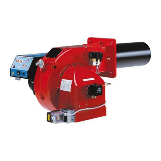
Горелка газовая одноступенчатая Cib Unigas NG 350 с современной газовой автоматикой в комплекте, настроенной на заводе.
Это горелка большой мощности новой серии IDEA. Это надежное и энергоэффективное решение для коммерческих и производстенных нужд.
Особенная геометрическая форма дроссельного клапана специально разработана для достижения линейной пропорции между углом раскрытия и расходом, способствует нормальному и эффективному по всему полезному объему горения.
Горелка, во всех своих модификациях, характеризуется некоторыми полезными функциональными доработками:
— быстро подключаемые к линии питания штепсельные вилки,
— механические компоненты, установленные на съемной опорной плите горелки,
— возможность отбора давления в камере сгорания,
— присоединительный фланец уменьшенной толщины, позволяющий уложиться в определенные габаритные размеры.
Положение головки сгорания регулируется с помощью градуированного штифта. Кроме того, газовая рампа, с соответствующими соединительными терминалами, может быть смонтирована как с левой стороны горелки, так и с правой.
Габаритные размеры:

Рабочее поле горелки:

Условия доставки:
- Доставка в пределах МКАД при заказе от 50000 рублей – бесплатно.
- Доставка в пределах МКАД при заказе менее 50000 рублей – 2500 рублей.
- Доставка за пределы МКАД – 35 рублей за км + Доставка в пределах МКАД.
- Доставка в регионы России до транспортной компании – бесплатно.
- Доставка в регионы России при заказе от 200000 рублей – бесплатно до Вашего города.
Варианты оплаты:
- Наличными курьеру при получении.
- Банковской картой при получении.
- Безналичным банковским переводом от частного или юридического лица.