SMART Digital DDA представляет собой компактный объемный, дозирующий насос с диафрагмой, двигателем с переменной скоростью вращения (двигатель PMS) и интеллектуальной электронной системой управления. Потребляет минимальное количество электроэнергии. Серия SMART Digital Dosing работает с полной длиной хода, чтобы обеспечить оптимальную точность, дозирования и всасывание даже для жидкостей с высокой вязкостью или дегазацией. Продолжительность каждого такта выпуска зависит от установки мощности, что обеспечивает оптимальный плавный и непрерывный расход. Монтажная панель обеспечивает быструю установку и обслуживание. Блок управления можно легко поворачивать в переднее, левое или правое положение. Колесо управления и разноцветная подсветка графического текстового ЖК-дисплей делают ввод в эксплуатацию интуитивно понятным. Элементы управления защищены прозрачной крышкой.
Система FlowControl (FCM) на основе датчиков обнаруживает неисправности непосредственно в дозирующей головке и отображает их в виде обычного текста в меню сигнализации, например. Воздушные пузыри, разрыв линии, избыточное давление. Интегрированная функция измерения расхода измеряет фактический расход и делает избыточное избыточное контрольное и контрольное оборудование (точность ± 1% от заданного значения в случае безотказной работы). Измеренный поток отображается и может быть интегрирован в управление процессом, например. SCADA. Кроме того, функция AutoFlowAdapt автоматически регулирует скорость работы насоса в соответствии с условиями процесса для поддержания целевого потока, даже напр. Различное противодавление или вспенивание пузырьков воздуха (принцип работы дегазации).
Дозирующая головка состоит из:
- Тефлоновой мембраны, материал которой является универсальным, химически стойким и обеспечивает длительный срок службы.
- Двойных шариковых (всасывающего и нагнетательного) клапанов для устранения перетечек жидкостей и максимальной точности дозирования.
- Клапана деаэрации для удаления воздуха из дозирующей головки в момент пуска, что облегчает запуск насоса.
- Датчика давления
Режимы работы:
- Ручное дозирование в мл / ч, л / ч или гал.
- Импульсное управление в мл / импульс (с функцией памяти).
- Аналоговое управление 0/4-20 мА (масштабируемое).
- Режим работы «Партия» в мл, л или гал.
- Таймер на основе функции «Партия» (дозирование по таймеру, недельным циклом).
- Цифровое управление (GENIbus подготовлены для модулей Grundfos CIU).
Другие особенности:
- Авто-деаэрация во время работы насоса в режиме ожидания, чтобы избежать аварии из-за воздушных пробок.
- SlowMode (анти-кавитация), позволяет уменьшать частоту вращения двигателя на 50% (maximum flow: 100 л/ч) и 25% (maximum flow: 50 л/ч), например, высокой вязкостью или дегазации жидкостей.
- Дисплей “Сервис” показывает, когда необходимо выполнить техобслуживание изнашиваемых деталей.
- Два варианта блокировки клавиш в зависимости от уровня защиты для защиты насоса от несанкционированного доступа.
- Дополнительная функция для отображения дополнительной информации, например, фактический ввод мА.
- Счетчик для общего дозированного объема (сброс), часы работы и т.д.
- Сохранять и загружать пользовательские настройки, а также изменять заводские настройки.
Сигнальные входы / выходы:
- Вход для импульсов, аналоговый 0 / 4-20 мА и внешний останов.
- Вход для сигнала низкого уровня и пустого резервуара.
- Два беспотенциальных выходных реле для максимального 30 В переменного / постоянного тока (настраиваемый, например, сигнал тревоги, сигнал хода, дозировка насоса, таймер и т. Д.).
- Выходной аналоговый 0 / 4-20 мА.
- Интерфейс связи Fieldbus (GENIbus, для подключения преобразователя fieldbus Grundfos CIU).
Предлагаем Вам купить Grundfos DDA 12-10 AR-PVC/E/C-F-31U2U2FG по выгодной цене 221 359 р.
Grundfos DDA 12-10 AR-PVC/E/C-F-31U2U2FG отличается высоким качеством и оптимальной ценой. Производитель известен во всем мире и предоставляет гарантию на свою продукцию.
Чтобы купить Grundfos DDA 12-10 AR-PVC/E/C-F-31U2U2FG в нашем интернет магазине вам достаточно оформить заказ онлайн на сайте
SMART Digital S
DIGITAL DOSING up to 30 l/h
DDA, DDC, DDE
Pumps and accessories
GRUNDFOS
DATA BOOKLET
2
SMART Digital S
1.
General data 3
Performance range . . . . . . . . . . . . . . . . . . . . . . . . . . . . . . . . . . . . . . . . . . . . . . . . . . . . . . . . . . . . . . . . . . . . . . . . . . . . 3
Features at a glance . . . . . . . . . . . . . . . . . . . . . . . . . . . . . . . . . . . . . . . . . . . . . . . . . . . . . . . . . . . . . . . . . . . . . . . . . . . 4
2.
Identification 6
Type key . . . . . . . . . . . . . . . . . . . . . . . . . . . . . . . . . . . . . . . . . . . . . . . . . . . . . . . . . . . . . . . . . . . . . . . . . . . . . . . . . . . . 6
3.
Functions 7
Overview of functions. . . . . . . . . . . . . . . . . . . . . . . . . . . . . . . . . . . . . . . . . . . . . . . . . . . . . . . . . . . . . . . . . . . . . . . . . . . 7
Functional description . . . . . . . . . . . . . . . . . . . . . . . . . . . . . . . . . . . . . . . . . . . . . . . . . . . . . . . . . . . . . . . . . . . . . . . . . . 8
Control cube DDA and DDC . . . . . . . . . . . . . . . . . . . . . . . . . . . . . . . . . . . . . . . . . . . . . . . . . . . . . . . . . . . . . . . . . . . . . 9
Menu . . . . . . . . . . . . . . . . . . . . . . . . . . . . . . . . . . . . . . . . . . . . . . . . . . . . . . . . . . . . . . . . . . . . . . . . . . . . . . . . . . . . . . 10
Operation modes . . . . . . . . . . . . . . . . . . . . . . . . . . . . . . . . . . . . . . . . . . . . . . . . . . . . . . . . . . . . . . . . . . . . . . . . . . . . . 11
Functions . . . . . . . . . . . . . . . . . . . . . . . . . . . . . . . . . . . . . . . . . . . . . . . . . . . . . . . . . . . . . . . . . . . . . . . . . . . . . . . . . . . 13
Wiring diagram, DDA . . . . . . . . . . . . . . . . . . . . . . . . . . . . . . . . . . . . . . . . . . . . . . . . . . . . . . . . . . . . . . . . . . . . . . . . . . 19
Wiring diagram, DDC . . . . . . . . . . . . . . . . . . . . . . . . . . . . . . . . . . . . . . . . . . . . . . . . . . . . . . . . . . . . . . . . . . . . . . . . . . 20
Wiring diagram, DDE-PR, -P . . . . . . . . . . . . . . . . . . . . . . . . . . . . . . . . . . . . . . . . . . . . . . . . . . . . . . . . . . . . . . . . . . . . 21
4.
Construction 22
DDA and DDC . . . . . . . . . . . . . . . . . . . . . . . . . . . . . . . . . . . . . . . . . . . . . . . . . . . . . . . . . . . . . . . . . . . . . . . . . . . . . . . 22
DDE . . . . . . . . . . . . . . . . . . . . . . . . . . . . . . . . . . . . . . . . . . . . . . . . . . . . . . . . . . . . . . . . . . . . . . . . . . . . . . . . . . . . . . . 23
5.
Dimensions 24
DDA and DDC . . . . . . . . . . . . . . . . . . . . . . . . . . . . . . . . . . . . . . . . . . . . . . . . . . . . . . . . . . . . . . . . . . . . . . . . . . . . . . . 24
DDE . . . . . . . . . . . . . . . . . . . . . . . . . . . . . . . . . . . . . . . . . . . . . . . . . . . . . . . . . . . . . . . . . . . . . . . . . . . . . . . . . . . . . . . 24
6.
Technical data 25
DDA . . . . . . . . . . . . . . . . . . . . . . . . . . . . . . . . . . . . . . . . . . . . . . . . . . . . . . . . . . . . . . . . . . . . . . . . . . . . . . . . . . . . . . . 25
DDC . . . . . . . . . . . . . . . . . . . . . . . . . . . . . . . . . . . . . . . . . . . . . . . . . . . . . . . . . . . . . . . . . . . . . . . . . . . . . . . . . . . . . . . 26
DDE . . . . . . . . . . . . . . . . . . . . . . . . . . . . . . . . . . . . . . . . . . . . . . . . . . . . . . . . . . . . . . . . . . . . . . . . . . . . . . . . . . . . . . . 27
7.
Pump selection 28
DDA, standard range . . . . . . . . . . . . . . . . . . . . . . . . . . . . . . . . . . . . . . . . . . . . . . . . . . . . . . . . . . . . . . . . . . . . . . . . . . 28
DDC, standard range . . . . . . . . . . . . . . . . . . . . . . . . . . . . . . . . . . . . . . . . . . . . . . . . . . . . . . . . . . . . . . . . . . . . . . . . . . 29
DDE, standard range . . . . . . . . . . . . . . . . . . . . . . . . . . . . . . . . . . . . . . . . . . . . . . . . . . . . . . . . . . . . . . . . . . . . . . . . . . 30
DDA, DDC, DDE, non-standard range. . . . . . . . . . . . . . . . . . . . . . . . . . . . . . . . . . . . . . . . . . . . . . . . . . . . . . . . . . . . . 31
8.
Accessories for small dosing pumps up to 60 l/h 33
Accessories overview . . . . . . . . . . . . . . . . . . . . . . . . . . . . . . . . . . . . . . . . . . . . . . . . . . . . . . . . . . . . . . . . . . . . . . . . . 33
Installation kits for dosing pumps. . . . . . . . . . . . . . . . . . . . . . . . . . . . . . . . . . . . . . . . . . . . . . . . . . . . . . . . . . . . . . . . . 34
Cables and plugs . . . . . . . . . . . . . . . . . . . . . . . . . . . . . . . . . . . . . . . . . . . . . . . . . . . . . . . . . . . . . . . . . . . . . . . . . . . . . 35
E-box for SMART digital S DDA . . . . . . . . . . . . . . . . . . . . . . . . . . . . . . . . . . . . . . . . . . . . . . . . . . . . . . . . . . . . . . . . . 36
Hoses. . . . . . . . . . . . . . . . . . . . . . . . . . . . . . . . . . . . . . . . . . . . . . . . . . . . . . . . . . . . . . . . . . . . . . . . . . . . . . . . . . . . . . 37
Foot valves FV . . . . . . . . . . . . . . . . . . . . . . . . . . . . . . . . . . . . . . . . . . . . . . . . . . . . . . . . . . . . . . . . . . . . . . . . . . . . . . . 38
Rigid suction lances RSL . . . . . . . . . . . . . . . . . . . . . . . . . . . . . . . . . . . . . . . . . . . . . . . . . . . . . . . . . . . . . . . . . . . . . . . 39
Injection units . . . . . . . . . . . . . . . . . . . . . . . . . . . . . . . . . . . . . . . . . . . . . . . . . . . . . . . . . . . . . . . . . . . . . . . . . . . . . . . . 43
Multi-function valves, pressure relief valves, pressure loading valves. . . . . . . . . . . . . . . . . . . . . . . . . . . . . . . . . . . . . 45
Pump connection kits and inlay kits . . . . . . . . . . . . . . . . . . . . . . . . . . . . . . . . . . . . . . . . . . . . . . . . . . . . . . . . . . . . . . . 48
Adapters. . . . . . . . . . . . . . . . . . . . . . . . . . . . . . . . . . . . . . . . . . . . . . . . . . . . . . . . . . . . . . . . . . . . . . . . . . . . . . . . . . . . 49
Dosing tanks . . . . . . . . . . . . . . . . . . . . . . . . . . . . . . . . . . . . . . . . . . . . . . . . . . . . . . . . . . . . . . . . . . . . . . . . . . . . . . . . 51
Water meter . . . . . . . . . . . . . . . . . . . . . . . . . . . . . . . . . . . . . . . . . . . . . . . . . . . . . . . . . . . . . . . . . . . . . . . . . . . . . . . . . 55
9.
Pumped liquids
10. Grundfos Product Center
56
57
SMART Digital S
1. General data
Performance range
p
[bar]
16
DDA 7.5-16
10
7
DDC 6-10
DDE 6-10
DDA 12-10
DDC 9-7 DDA 17-7
4
DDC 15-4
DDE 15-4
0
Fig. 1
Performance range
6 7.5
9 12 15 17
DDA 30-4
30 Q [l/h]
1
3
1
SMART Digital S
Features at a glance
Precise and easy setting / usability and interaction
The operator can easily install the pump and set it to discharge exactly the quantity of dosing liquid required for the application. In the display, the setting of the pump is read out directly, the flow is shown in ml/h, l/h, or gph.
The click wheel (turn-and-push knob) and the graphical LC display with plain-text menu in more than
25 languages make commissioning and operation intuitive. As the LCD is backlit in different colours, the pump status can be seen from a distance (traffic-light concept).
Fig. 2
DDA, DDC, DDE
Digital Dosing
TM
The SMART Digital S generation DDA, DDC and DDE with powerful variable-speed stepper motor brings state-of-the-art technology to perfection.
Combined expert knowledge and the patented solutions set future standards. Traditional technologies such as stroke length or stroke frequency adjustment with synchronous motor or solenoid drive become a thing of the past.
Unique flexibility with only a few variants
The included click-stop mounting plate makes the pump more flexible. Three different positions are possible without using any additional accessories, such as wall brackets. Service and pump exchange can now be done easily and fast just by clicking the pump in and out of the mounting plate.
The control cube on the DDA and DDC pump can be lifted and turned easily into three different positions: front, left or right.
Fig. 3
Modularity of the control cube
A turn-down ratio of up to 1:3000, a wide supply voltage range (100-240 V; 50/60 Hz), combined connection sets and other features reduce the models and variants to a minimum.
Fig. 4
Display DDA, DDC
Thanks to a variety of operation modes, signal inputs and outputs, the pump can easily be integrated into every process.
Advanced process reliability
An intelligent drive and microprocessor control ensures that dosing is performed precisely and with low pulsation, even if the pump is dosing high-viscosity or degassing liquids. Malfunctions, caused e.g. by air bubbles, are detected quickly by the maintenance-free
FlowControl system and then displayed in the alarm menu.
The AutoFlowAdapt function automatically adjusts the pump according to the process conditions, e.g. varying backpressure. The integrated flow measurement makes additional monitoring and control equipment redundant.
Designed to save costs
In general, the investment for a dosing pump installation is low compared to its life cycle costs including the cost of the chemicals. The following features make the SMART Digital S DDA, DDC and
DDE pumps contribute to low life cycle costs:
• No underdosing or overdosing due to high dosing accuracy and FlowControl
• Longer maintenance intervals thanks to the universal chemical resistance of the full-PTFE diaphragm
• Reduced energy consumption thanks to state-of-the-art drive technology.
4
SMART Digital S
Three application-oriented type ranges
DDA: High-end pump range for extended flow and pressure ranges with sensor-based FlowControl and measurement functions for challenging industrial applications, e.g.
• Process water
• Food and beverage
• Ultrafiltration and reverse osmosis
• Pulp and paper
• Boiler feed water
• CIP (Cleaning-In-Place).
DDC: User-friendly pump range with standard inputs and outputs for common applications, e.g.
• Drinking water
• Waste water
• Swimming pool water
• Cooling tower
• Chemical industry.
DDE: Low-budget pump range with basic functions including manual operation or control via PLC for OEM applications, e.g.
• Car wash
• Irrigation.
1
5
2
SMART Digital S
2. Identification
Type key
Example: DDA 7.5-16 AR-PP/V/C-F-3 1 U2U2 F G
Type range
DDA
7.5-16 AR-PP/V/C-F-3 1 U2U2 F G
DDA
DDC
DDE
Max. flow [l/h]
DDA
7.5
-16 AR-PP/V/C-F-3 1 U2U2 F G
Maximum pressure [bar]
DDA 7.5-
16
AR-PP/V/C-F-3 1 U2U2 F G
Control variant
DDA 7.5-16
AR
-PP/V/C-F-3 1 U2U2 F G
B Basic (DDE)
P
PR
A
AR
FC
FCM
B with pulse mode (DDE)
P with relay output (DDE)
Standard (DDC)
A with alarm relay and analog input (DDA, DDC)
AR with FlowControl (DDA)
FC with flow measurement (DDA)
Dosing head variant
DDA 7.5-16 AR-
PP
/V/C-F-3 1 U2U2 F G
PP Polypropylene
PVC
PV
SS
Polyvinyl chloride**
PVDF (polyvinylidene fluoride)
Stainless steel 1.4401
Gasket material
DDA 7.5-16 AR-PP/
V
/C-F-3 1 U2U2 F G
E
V
T
EPDM
FKM
PTFE
Valve ball material
DDA 7.5-16 AR-PP/V/
C
-F-3 1 U2U2 F G
C
SS
Ceramic
Stainless steel 1.4401
Control cube position
DDA 7.5-16 AR-PP/V/C-
F
-3 1 U2U2 F G
F Front-mounted (change to left and right possible)
X No control cube (DDE)
Supply voltage
DDA 7.5-16 AR-PP/V/C-F-
3
1 U2U2 F G
3 1 x 100-240 V, 50/60 Hz
Valve type
DDA 7.5-16 AR-PP/V/C-F-3
1
U2U2 F G
1
2
Standard
Spring-loaded
0.1 bar suction opening pressure
0.1 bar discharge opening pressure
Connection, suction/discharge
DDA 7.5-16 AR-PP/V/C-F-3 1
U2U2
F G
U2U2
Union nut G 5/8″ with parts for hose connection
4/6 mm, 6/9 mm, 6/12 mm, 9/12 mm
U7U7
AA
VV
XX
Union nut G 5/8″ with parts for hose connection
0.17″ x 1/4″; 1/4″ x 3/8″; 3/8″ x 1/2″
Union nut G 5/8″ with threaded connection Rp 1/4″, internal thread
Union nut G 5/8″ with threaded connection 1/4″ NPT, internal thread
No connections included
I001
*
I002
*
I003
*
I004
*
Hose 4/6 mm (up to 7.5 l/h, 13 bar)
Hose 9/12 mm (up to 60 l/h, 9 bar)
Hose 0.17″ x 1/4″ (up to 7.5 l/h, 13 bar)
Hose 3/8″ x 1/2″ (up to 60 l/h, 10 bar)
Mains plug
DDA 7.5-16 AR-PP/V/C-F-3 1 U2U2
F
G
F
B
EU
USA, Canada
E
J
I
G
L
UK
Australia, New Zealand
Switzerland
Japan
Argentina
Design/approval
DDA 7.5-16 AR-PP/V/C-F-3 1 U2U2 F
G
G
A
Grundfos red
Grundfos green
B
X
C
Grundfos black
Neutral/black
China approval
Special variant
DDA 7.5-16 AR-PP/V/C-F-3 1 U2U2 F G
C3
C3 Inspection Certificate 3.1 (EN 10204)
* Installation set: Including 2 pump connections, foot valve, injection unit, 6 m PE discharge hose, 2 m PVC suction hose, 2 m PVC deaeration hose (4/6 mm)
** PVC dosing heads only up to 10 bar
6
SMART Digital S
3. Functions
Overview of functions
Control variant: FCM
General
Digital Dosing: Internal stroke speed and frequency control
Mounting plate (basic/wall mounting)
Control panel, see page
9
Control cube mountable in three positions: front, left, right
Control panel position: front-fitted
Transparent protective cover for control elements
Capacity setting in millilitres, litres or US-gallons
Graphical display with background light in four colours for status indication: white, green, yellow, red
Plain-text menu in different languages
Turn-and-push knob (click wheel) for easy navigation
Capacity adjustment knob (0.1 — 100 %)
Start/Stop key
100 % key (deaearation)
Operation mode switch (manual/pulse)
Operation modes, see page
11
Manual speed control
Pulse control in ml/pulse
Pulse control (1:n)
Analog control 0/4-20 mA
Batch control (pulse-based)
Dosing timer cycle
Dosing timer week
Fieldbus control
Functions, see page
13
Auto deaeration also during pump standby
FlowControl system with selective fault diagnosis
Pressure monitoring (min/max)
Flow measurement
AutoFlowAdapt
SlowMode (anti-cavitation)
Calibration mode
Scaling of analog input
Service information display
Relay setting: alarm, warning, stroke signal, pump dosing, pulse input*
Relay setting (additionally): timer cycle, timer week
Inputs/outputs, see page 14
Input for external stop
Input for pulse control
Input for analog 0/4-20 mA control
Input for low-level signal
Input for empty tank signal
Output relay (2 relays)
Output analog 0/4-20 mA
Input/Output for GENIbus
Input/Output for E-box (e.g. E-box 150 with Profibus DP)
●
●
●
●
●
●
●
●
●
●
* DDE-PR: relay 1: alarm; relay 2: low-level signal, stroke signal, pulse input
●
●
●
●
●
●
●
●
●
●
●
●
●
●
●
●
●
●
●
●
●
●
●
●
●
●
●
DDA
FC
●
●
●
●
●
●
●
●
●
●
●
●
●
●
●
●
●
●
●
●
●
●
●
●
●
●
●
●
●
●
●
●
●
●
●
AR
●
●
●
●
●
●
●
●
●
●
●
●
●
●
●
●
●
●
●
●
●
●
●
●
●
●
●
●
●
●
●
●
●
●
●
●
●
●
●
●
●
●
●
●
●
●
AR
DDC
A
●
●
●
●
●
●
●
●
●
●
●
●
●
●
●
●
●
●
●
●
●
●
●
●
●
●
●
●
●
PR
DDE
P
●
●
●
●
B
●
●
● ● ●
●
●
●
●
●
●
●
●
●
●
●
●
●
●
●
●
●
●
●
●
●
●
3
7
3
Functional description
The electronically controlled variable-speed motor
(stepper motor) of the DDA, DDC and DDE pumps provides optimum control of the stroke speed.
The duration of each discharge stroke varies according to the capacity set, resulting in optimum discharge flow in any operating situation, while the duration of each suction stroke is constant (see figure below).
The advantages are as follows:
• The pump always operates at full stroke length, irrespective of the capacity set; this ensures optimum accuracy, priming and suction.
• A capacity range of up to 1:3000 (turn-down ratio) reduces variants and spare parts.
• Smooth and continuous dosing ensuring an optimum mixing ratio at the injection point without needing static mixers.
• Significant reduction of pressure peaks, preventing mechanical stress on wearing parts such as diaphragm, tubes, connections, resulting in extended maintenance intervals.
• The installation is less affected by long suction and discharge lines.
• Easier dosing of high-viscosity and degassing liquids (SlowMode).
The optimum dosing control shown below takes place in any operation mode.
SlowMode Capacity setting
100 % —
Discharge
Suction
Discharge
50 % —
Suction
Discharge
10 % —
Suction
Discharge
10 % 50 %
Suction
Extended suction stroke (SlowMode)
Fig. 5
Relation between stroke-frequency adjustment and capacity
SMART Digital S
Duration
Duration
Duration
Duration
8
SMART Digital S
Control cube DDA and DDC
DDA and DDC pumps are supplied with front-mounted control cube. The position of the control cube can easily be changed by unfastening 2 screws, lifting the cube, turning it to the left or to the right and fastening both screws again.
Fig. 6
Two of three possible control cube positions
Operating elements DDA and DDC
1
2
Operation
Manual
7.5
l/h
7.49 l/h
3
4
Fig. 7
Operating elements DDA and DDC
Pos.
Description
1
2
3
4
Graphical LC display
[Start/Stop] key
Click wheel
[100%] key
The click wheel guides the user quickly and easily through the plain-text menu.
If the maximum capacity is required over a short period of time, for example during start-up, press the 100 % key. To set the pump to run for a specific number of seconds at maximum capacity, press the 100 % key and turn the click wheel clockwise simultaneously.
Operating elements DDE
0.6
0.5
0.4
1
0.8
0.3
0.2
0.15
1.5 2
0%
3 4 5 6
8
10
15
20
30
80
60
40
50
100
%
100%
Fig. 8
Operating elements DDE
5
6
3
4
7
1
2
Pos.
Description
5
6
7
3
4
1
2
Status LED pulse (DDE-PR and DDE-P)
Operation mode switch (DDE-PR and DDE-P)
Status LED manual
Capacity adjustment knob
Logarithmic scale
100 % key (DDE-PR and DDE-P)
Mechanical lock
With the capacity adjustment knob the capacity of the pump can easily be adjusted in % of the maximum flow.
Applies to DDE-PR, DDE-P
When holding down the operation mode switch, the pump changes from manual operation to pulse mode or vice versa.
If the maximum capacity is required over a short period of time, for example during start-up, press the 100 % key.
Depending on the selected operation mode, the respective status LED (pulse or manual) is activated according to the following table:
LED colour
Green (flashing)
Green
Red-green (flashing)
Yellow
Red
Red (flashing)
Pump status
Stopped
Running
External stop
Low level (warning)
Empty tank (alarm)
Motor blocked (alarm)
3
9
3
SMART Digital S
Menu
The DDA and DDC dosing pumps feature a user-friendly plain-text menu. The menu consists of 4 tabs: Operation;
Info; Alarm; Setup. During initial start-up, all menu text appears in the English language. The menu can be set to display other languages.
This example applies to DDA pumps:
Operation
Manual
7.50
l/h
7.49 l/h
Setup
Language
Operation mode
Analog output
SlowMode
………………………..
English >
Manual >
Input >
Off >
Info
Fr 12.12.2009
Counter
Service
Service kit
………………………..
12:34
>
—
Alarm
1
Low level
12.12.2009
2
Empty
11.12.2009
13:34
14:34
Fig. 9
Menu overview (example of main menus)
The menu text appears in more than 25 languages on a big graphical display, backlit in four different colours according to the traffic light concept.
Display
White
Green
Yellow
Red
Fault
—
—
Warning
Alarm
Pump status
Stop Standby
Running
Stop Standby
10
SMART Digital S
Operation modes
Manual control
The pump ensures constant dosing according to the quantity set in l/h or ml/h or gph by means of the click wheel. The pump automatically changes between the measuring units.
Setting range
Setting range*
Pump type
DDA 7.5-16
DDA 12-10
DDA 17-7
DDA 30-4
DDC 6-10
DDC 9-7
DDC 15-4
DDE 6-10
DDE 15-4
From [l/h]
0.0025
0.0120
0.0170
0.0300
0.0060
0.0090
0.0150
0.0060
0.0150
To [l/h]
7.5
12.0
17.0
30.0
6.0
9.0
15.0
6.0
15.0
* When the SlowMode function is enabled the max. flow is reduced
(see page 13
)
Pulse control
The pump doses in proportion to an external potential-free pulse signal, for example from a water meter. There is no direct relation between pulses and dosing strokes. The pump automatically calculates its optimal speed to ensure that the required quantity is dosed for each incoming pulse.
Applies to DDA and DDC
The quantity to be dosed is set in ml/pulse. The pump adjusts its speed according to two factors:
• the frequency of external pulses
• the set quantity per pulse.
Setting range
Pump type
DDA 7.5-16
DDA 12-10
DDA 17-7
DDA 30-4
DDC 6-10
DDC 9-7
DDC 15-4
Setting range [ml/pulse]
0.0015 — 14.9
0.0029 — 29.0
0.0031 — 31.0
0.0062 — 62.0
0.0016 — 16.2
0.0017 — 16.8
0.0032 — 31.6
The frequency of external pulses is multiplied by the set quantity. If the product exceeds the maximum flow of the pump, a maximum of 65,000 pulses can be stored for later processing with the Memory pulse function, when activated.
Applies to DDE-PR, DDE-P control variant
The dosing quantity per pulse is adjusted with the adjustment knob according to the scale from 0.1 to
100 % of the stroke volume. The pump adjusts its speed according to two factors:
• the frequency of external pulses
• the set percentage of stroke volume.
Setting range, DDE-PR, DDE-P
Pump type
DDE 6-10
DDE 15-4
Setting range [ml/pulse]
0.0008 — 0.81
0.0016 — 1.58
Analog 0/4-20 mA control
Applies to DDA and DDC-AR control variant
The pump ensures dosing according to an external analog signal. The dosed capacity is proportional to the input value in mA.
Operation mode
4-20
0-20
Input signal
≤ 4.1 mA
≥ 19.8 mA
≤ 0.1 mA
≥ 19.8 mA
Dosing capacity
0 %
100 %
0 %
100 %
Dosing capacity
Q [%]
100
80
60
40
20
4 — 20 mA
0
0 4 8
0 — 20 mA
12 16 20
Input signal
[mA]
Fig. 10
0/4-20 mA control
Applies to DDA
With the analog scaling function, the curve can be individually drawn between two arbitrary points: l and l
2
/Q
2
.
1
/Q
1
Dosing capacity
Q [%]
100
80
60
40
20
0
0 4 8 12 16 20
Input signal
[mA]
Fig. 11
Analog scaling
3
11
3
SMART Digital S
Pulse-based batch control
Applies to DDA
The set quantity is dosed in batches within the set dosing time (t
1
). A batch is dosed every time the pump receives an external pulse. If the pump receives new pulses before a batch is completed, these pulses will be ignored. In the event of interrupts such as external stop or alarm, incoming pulses will also be ignored.
After ending of the interrupts, a new batch will be dosed with the next incoming pulse.
Batch volume t
1 t
1
Pulse Pulse
Fig. 12
Pulse-based batch control
Setting range
Setting range
Pump type
DDA 7.5-16
DDA 12-10
DDA 17-7
DDA 30-4
From
[ml/batch]
0.74
1.45
1.55
3.10
To [l/batch]
999
999
999
999
Resolution [ml]*
0.09
0.18
0.19
0.39
* Due to the digital motor control, down to 1/8 of the dosing volume can be dosed.
Dosing timer cycle
Applies to DDA
After a start delay (t
2
) the set batch volume is repeatedly dosed in the set cycle time (t
3 time (t
1
). The dosing
) can be adjusted. Batch dosing is stopped during any interrupt, e.g. power supply failure or external stop while the time continues running in the background (real-time clock). After ending of the interrupt, batch dosing proceeds according to the current status in the timeline.
Batch volume
Dosing timer week
Applies to DDA
The integrated real-time clock features also batch dosing based on a weekly period. There is a maximum of 16 procedures per week. Each dosing procedure consists of:
• Batch volume
• Dosing time
• Start time
• 1 to 7 weekdays (Monday to Sunday).
In case several procedures are overlapping, the procedure with the highest flow rate has the highest priority. Batch dosing is stopped during any interrupt, e.g. power supply failure or external stop, while the time continues running in the background (real-time clock). After ending of the interrupt, batch dosing proceeds according to the current status in the timeline.
0:00
1 1 1
6:00
4 4
12:00
2 2
18:00
0:00
3
Mo Tu
3 3
We
3
Th Fr
3
Sa
3
3
Su
Fig. 14
Dosing timer week (example with 4 procedures)
Setting range
The batch volume setting range corresponds to the pulse-based batch control setting range.
t
1 t
1 t
2 t
3
Fig. 13
Dosing timer cycle
Setting range
The batch volume setting range corresponds to the pulse-based batch control setting range.
12
SMART Digital S
Functions
SlowMode
Applies to DDA, DDC
When the SlowMode function (anti-cavitation) is selected, the pump extends and smooths its suction stroke. This results in a softer suction stroke.
The SlowMode function is used in these situations:
• when pumping high-viscosity liquids
• when pumping degassing liquids
• when the suction line is long
• when the suction lift is high.
Depending on the application, the motor speed during the suction stroke can be reduced individually to approximately 50 % or 25 % of the normal motor speed.
The maximum pump capacity is reduced accordingly.
See pages 25 and
26 for further details.
Auto deaeration
Applies to DDA
The auto deaeration function avoids breakdown of the dosing process due to air-locking, when dosing degassing liquids such as sodium hypochlorite.
During long dosing breaks, e.g. at the weekend or overnight, air-bubbles can form in the suction line and get into the dosing head. If too much air is in the dosing head, and the dosing process is started again, no liquid will be dosed (air-lock). Software-controlled diaphragm movements at regular intervals encourage the air bubbles to rise and finally to be displaced out of the dosing head.
These movements are executed
• when the pump is not stopped and
• during dosing breaks (e.g. external stop or no incoming pulses).
Calibration
Applies to DDA and DDC
The pump is calibrated in the factory at the nominal pressure of the respective pump type (see maximum pressure Technical data page
25 ,
26
). After start-up, the dosing pump can be calibrated for the actual installation to ensure that the displayed value (ml, l or gph) is correct. A calibration program in the setup menu facilitates this process. The AutoFlowAdapt function keeps the dosing precision (DDA-FCM control variant), even if the backpressure changes.
For the description of the AutoFlowAdapt function, see page
18
.
External stop
Applies to DDA, DDC, DDE-PR, DDE-P
With the external stop function, the pump can be stopped from a remote place via an external contact. It is not recommended to switch on and off the power supply as it was usual when working with a conventional dosing pump. When working with microprocessor-controlled digital dosing pumps, the external stop signal has to be used, in order to keep the optimal dosing precision and to prevent damages to the electronics.
When activating the external stop signal, the pump changes from running to standby . The operation display shows an activated external stop .
The signal input can be set to normally open (default) or normally closed contact.
Counters
Applies to DDA and DDC
The pump displays resettable and non-resettable counters in the info menu tab.
Counter
Volume
Operating hours
Motor runtime
Strokes
Power on/off
Description
Accumulated dosed quantity in litres or
US gallons
Accumulated number of operating hours
(power-on)
Accumulated number of motor runtime hours
Accumulated number of dosing strokes
Accumulated number of times the mains supply has been switched on
Resettable
Yes
No
No
No
No
3
13
3
SMART Digital S
Service display
Applies to DDA, DDC
Due to the optimised construction and the smooth digital dosing principle, the service periods are more than twice as long, if compared to conventional pumps.
However, the wear parts have to be exchanged in regular intervals in order to keep the dosing precision and the process reliability at a high level. The service display in the pump shows when service of the wear parts is required. The displayed service kit product number makes service more convenient. The following information is displayed in the Info display:
Display
Service
Service kit
—
Soon
Now
8-digit Grundfos product number
Reset service system
Description
No service required
Order parts for service soon
Service must be performed now
The service kit contains all parts needed for standard maintenance: diaphragm + valves
After performing the service, reset the system
The following service messages appear, depending on what happens first:
Display
Service soon
Service now
* Applies to DDA only
Motor runtime
[h]
7,500
8,000
Regular intervals
[months]*
23
24
In case of difficult liquids the service intervals can be shorter and service has to be performed earlier.
Level control
Applies to DDA, DDC, DDE-PR and DDE-P
The pump can be connected to a dual level control unit for monitoring of the chemical level in the tank. The pump can react to two level signals:
Pump reaction*
Level sensors
Low-level signal
Empty tank signal
DDA, DDC
• Display is yellow
(Warning)
• is flashing
• Pump continues running
• Display is red (Alarm)
• is flashing
• Pump stops
DDE-PR, DDE-P
• LED lights up in yellow
• Pump continues running
• LED lights up in red
• Pump stops
* Depending on the pump model and settings, the relay outputs can be activated (see
Relay output
, page 14
)
Relay output
Applies to DDA, DDC-AR and DDE-PR
The pump can activate 2 external signals by means of built-in relays switched via internal potential-free contacts. Depending on the process control requirements, the following relay output settings can be chosen:
Applies to DDA and DDC-AR
Signal
Description
Relay 1 Relay 2
Alarm*
Warning*
Alarm
Warning
Timer week
Display red, pump stopped
(e.g. empty tank signal, etc.)
Display yellow, pump running
(low level signal, etc.)
Stroke signal Stroke signal Every completed stroke
Pump dosing Pump dosing* Pump is running and dosing
Pulse input Pulse input
Bus control Bus control
Timer cycle
Every pulse coming in from pulse input
Set by a command in the Bus
communication function (page 15 )
(only DDA)
Timer can be set in menu: on-time, cycle-time, start delay (only DDA)
Timer can be set in menu: procedure, on-time, start time and weekdays (only
DDA)
NO*
NC
Contact type
NO*
NC
Normally Open Contact
Normally Closed Contact
* default setting
Applies to DDE-PR control variant
Relay 1
Alarm*
NO*
NC
Signal
Description
Relay 2
Low level*
Empty tank, motor blocked
Low level tank
Stroke signal Every completed stroke
Pulse input Every pulse coming in from pulse input
Contact type
NO*
NC
Normally Open Contact
Normally Closed Contact
* default setting
14
SMART Digital S
Analog output
Applies to DDA
In addition to the analog input (operation mode: analog
0/4-20 mA) the pump is also equipped with an analog
0/4-20 mA output signal. Depending on the process control requirements, the following analog output settings are available:
Setting
Description of analog output signal
Control variant
FCM FC AR
Output = Input
Actual flow
Backpressure
Bus control
Analog feedback signal (not for master-slave application).
The analog input signal is mapped 1:1 to the analog output.
Flow measured in the dosing head
(Flow Measurement page
18
)
Backpressure measured in the dosing head
(Pressure monitoring page
18 )
Set by a command in the bus communication (see below)
X
X
X
X
X
X*
X
X
X
X*
X
* Output signal is calculated based on motor speed and pump status
(target flow rate).
Bus communication
Applies to DDA
The pump is equipped with a built-in module for
GENIbus communication. With the additional E-Box module (please see page
36 ) the pump can be
integrated into a fieldbus network.
The bus communication possibilities enable remote monitoring and setting via the fieldbus system.
Key lock and mechanical lock
Applies to DDA, DDC
To protect the pump from maloperation, a key lock can be set by entering a 4-digit PIN-code. When the pump is locked, it is still possible to navigate through the menus Alarm and Info and to acknowledge alarms. Two levels of protection are available:
• Settings: the keys and 100% are still available.
• Settings + keys: the keys locked.
and
100%
are also
For temporary (2 minutes) or final deactivation the preset 4-digit pin-code has to be entered again.
Applies to DDE
The adjustment knob can be locked with a locking screw to fix the current setting.
Basic settings
Applies to DDA, DDC
With load factory settings, the pump can be reset to the default settings. In addition, with save customer settings, the current configuration of the pump is stored and can be activated later by load customer settings. The latest saved configuration is stored in the memory.
Units
Applies to DDA, DDC
It is possible to select metric units (litre/millilitre/bar) or
US units (US gallons/psi). Depending on the operation mode and menu, the following units are displayed:
Operation mode/Function
Manual control
Pulse control
Analog 0/4-20 mA control
Batch control
(pulse- or timer-based)
Calibration
Volume counter
Pressure monitoring
Metric units
ml/h or l/h ml/ ml/h or l/h ml or l l ml bar gal ml gal psi
US units
gph ml/ gph
Fig. 15
DDA with E-box
3
15
3
SMART Digital S
Additional display
Applies to DDA, DDC
The additional display function provides further useful status information, e.g. the target flow rate as well as the actual flow rate. The value is shown in the operation display together with the corresponding symbol.
Operation
Manual
7.50
l/h
7.49 l/h
Additional display
Fig. 16
Additional display
The following additional information can be selected:
Settings Description
Depending on the operation mode:
Actual flow (manual, pulse)
1)
Default display
Dosed volume
Actual flow
Backpressure
Target flow (pulse)
Input current (analog)
4)
Remaining batch volume (batch, timer)
3)
Time until next batch (timer)
3)
Total dosed volume (Counters see page
13 )
Actually measured flow
1)
Current backpressure in the dosing head
2)
1) Only DDA-FCM control variant
2) Only DDA-FCM/FC control variant
3) Only DDA pumps
4) Only DDA pumps and DDC-AR control variant
FlowControl
Applies to DDA-FC/FCM
Fig. 17
DDA FlowControl
The pump monitors the dosing process of liquids when the FlowControl function is activated. Although the pump is still operating, some influences such as air bubbles may cause reduced flow rates or even stop the dosing process. For optimal process safety and reliability, the activated FlowControl function immediately detects and displays the following malfunctions:
• Overpressure
• Discharge line burst
• Air bubbles in the dosing head
• Cavitation at the suction side
• Suction valve leakage
• Discharge valve leakage.
The unique FlowControl is based on an intelligent and maintenance-free sensor integrated in the dosing head. During the dosing process, the sensor measures the actual pressure and sends the measured value to the microprocessor in the pump. An internal indicator diagram is generated combining the actual pressure value with the diaphragm position (stroke length).
With it, the dosing process is monitored, as the different malfunctions can immediately be detected due to their specific deviations in the curve.
Compressible air bubbles, for instance, will reduce the discharge phase and the stroke volume (see fig.
18
).
The sensitivity and the delay of the FlowControl function can be adjusted individually.
FlowControl requires a minimum backpressure of
2 bar. Grundfos recommend an additional spring-loaded valve (approx. 3 bar) on the discharge side for dosing low capacities (< 1 l/h) (please see page
46
).
16
SMART Digital S
Pressure
Trouble-free dosing stroke
1
2
Air bubbles disturbing the dosing stroke
4
Stroke length
Fig. 18
Indicator diagram
3
4
1
2
Compression phase
Discharge phase
Expansion phase
Suction phase
3
3
17
3
SMART Digital S
Pressure monitoring
Applies to DDA-FC/FCM
The integrated pressure sensor measures the actual pressure of the system, which is shown in the display.
A maximum pressure can be set. If the pressure in the system exceeds the set maximum (e.g. caused by a closed valve), the pressure monitoring function stops the dosing process immediately. As soon as the backpressure falls below the set maximum, the dosing process is continued. In case the pressure drops below the minimum limit (e.g. caused by a burst discharge line) the pump stops and major chemical spills are prevented.
Pressure setting range
Pump type
DDA 7.5-16
DDA 12-10
DDA 17-7
DDA 30-4
Fixed min. pressure
[bar]*
< 2
< 2
< 2
< 2
Adjustable max. pressure
[bar]**
3 … 17 (default)
3 … 11 (default)
3 … 8 (default)
3 … 5 (default)
* Can be either set as a warning (pump keeps running) or as an alarm (pump stops)
** The adjustable max. pressure is equivalent to the max. operating pressure plus 1 bar
Flow measurement
Applies to DDA-FCM
The pump can precisely measure and display the actual dosing flow. Via the analog 0/4-20 mA output, the actual flow signal can easily be integrated in any process control system, without needing any additional measurement equipment.
The Flow measurement function is based on an indicator diagram as described in FlowControl
(page
16 ). Accumulating the length of each discharge
stroke phase and multiplying it with the stroke frequency results in the displayed actual flow.
Any malfunctions, such as air bubbles or lower backpressure, will result in a reduced or increased actual flow rate. When the AutoFlowAdapt function
(page 18 ) is activated, the pump compensates these
influences by correcting the stroke speed.
AutoFlowAdapt
Applies to DDA-FCM
When activating the AutoFlowAdapt function even environmental changes will be compensated, so that the required target flow rate will be achieved.
The integrated AutoFlowAdapt makes additional monitoring and control devices redundant.
The AutoFlowAdapt function is based on:
• FlowControl: malfunctions are detected
• Pressure monitoring: system pressure changes are detected
• Flow measurement: deviations in the target flow are detected.
Examples:
• FlowControl detects air bubbles in the system.
Due to a special motor drive strategy and a certain speed increase, the pump will try to keep the flow rate constant. This is especially important when dosing degassing liquids.
• In general, increasing system pressure reduces the stroke volume whereas falling system pressure increases the stroke volume. The AutoFlowAdapt function compensates this by automatically and continuously adapting the motor speed.
Despite fluctuating system pressure, dosing accuracy is maintained.
18
SMART Digital S
Wiring diagram, DDA
2
3
1
4
4
1
3
2
2
3
1
5
4
2
3
1
4
Sensor
FlowControl input
1
GND
2
3
►
4
1
2
3
GND
Cable 1
Analog/external stop/pulse
Product No.
2 m cable: 96609014
5 m cable: 96609016
Cable 2
Level input see page
39
, suction lances
Cable 1: Analog, external stop and pulse input
5
GND
4
3
BUS
2
BUS
1
Cable 3
GENIbus, analog output
Product No.
2 m cable: 96632921
5 m cable: 96632922
3
4
2
1
2
1
Cable 4
Relay output
Product No.
2 m cable: 96609017
5 m cable: 96609019
Function
Analog
External stop
Pulse
Cable 2: Level input
1/brown
GND/ (-) mA
GND
GND
2/white
(+) mA
Pin holes
3/blue
X
4/black
X
Function
Low level
Empty tank
Cable 3: GENIbus, analog output
1
X
2
X
Pin holes
3
GND
GND
4
Function
GENIbus
Analog output
Cable 4: Relay output
1/brown
+30 V
2/white
GENI bus A
Pin holes
3/blue
GENI bus B
4/black
(+) mA
5/yellow-green
GND
GND/ (-) mA
Plug type
mA signal
Contact
Contact
Plug type
Contact
Contact
Plug type
Bus mA signal
Function
Relay 1
Relay 2
1/brown
X
2/white
X
Pin holes
3/blue
X
4/black
X
Plug type
Contact
Contact
3
19
3
Wiring diagram, DDC
2
3
1
4
4
1
3
2
2
3
1
4
SMART Digital S
3
►
4
1
GND
2
Cable 1
Analog/external stop/pulse
Product No.
2 m cable: 96609014
5 m cable: 96609016
1
2
3
GND
Cable 2
Level input see page
39 , suction
lances
Cable 1: Analog, external stop and pulse input
Function
Analog*
External stop
Pulse
Cable 2: Level input
1/brown
GND/ (-) mA
GND
GND
2/white
(+) mA
Pin holes
3/blue
X
1
X
2
X
Pin holes
3
GND
GND
Function
Low level
Empty tank
Cable 4: Relay output*
Function
Relay 1
Relay 2
* applies to DDC-AR
1/brown
X
2/white
X
Pin holes
3/blue
X
4
4/black
X
3
4
2
1
2
1
Cable 4
Relay output
Product No.
2 m cable: 96609017
5 m cable: 96609019
4/black
X
Plug type
mA signal
Contact
Contact
Plug type
Contact
Contact
Plug type
Contact
Contact
20
SMART Digital S
Wiring diagram, DDE-PR, -P
4
1
3
2
2
3
1
4
2
3
1
4
1
2
3
GND
Cable 2
Level input see page
39 , suction
lances
Cable 1: External stop and pulse input
Function
External stop
Pulse
Cable 2: Level input
1/brown
GND
GND
Function
Low level
Empty tank
Cable 4: Relay output*
Function
Relay 1 (Alarm)
Relay 2 (see page
14 )
* applies to DDE-PR
1
X
1/brown
X
2/white
Pin holes
3/blue
X
4/black
X
2
X
4
1
GND
3
Ź
Cable 1
External stop/pulse
Product No.
2 m cable: 96609014
5 m cable: 96609016
3
4
2
1
2
1
Cable 4
Relay output
Product No.
2 m cable: 96609017
5 m cable: 96609019
Pin holes
3
GND
GND
4
2/white
X
Pin holes
3/blue
X
4/black
X
Plug type
Contact
Contact
Plug type
Contact
Contact
Plug type
Contact
Contact
3
21
4
SMART Digital S
4. Construction
DDA and DDC
12
13 14 15 16 17 18 19 20 21 22
11
10
9
8
7
6
5
4
3
2
1
Fig. 19
Sectional drawing, DDA
Construction
The DDA and DDC pumps are motor-driven diaphragm dosing pumps consisting of the following main parts:
Dosing head:
Patented design with a minimum of clearance space optimised for degassing liquids.
With integrated deaeration valve for priming and venting complete with connection for a 4/6 mm or 0.17″ x 1/4″ tubing. DDA-FCM/FC pumps have an integrated pressure sensor in the dosing head.
Valves:
Double-ball discharge and suction valve* design for less clearance space — optimised for degassing liquids. Spring-loaded valves for higher viscosities are available as an option.
Connections:
Robust and easy-to-use connection packages for various sizes of tubing or pipes.
Diaphragm:
Full PTFE diaphragm designed for long life and universal chemical resistance.
Flange:
With separation chamber, safety diaphragm and drain hole.
Drive unit:
Positive return crank with patented noiseless spur gear drive, energy recovery spring for high efficiency (only DDA), stepper motor, all mounted in a robust gear housing.
Control cube:
Containing operation electronics with display, keys, click-wheel and protective cover.
Housing:
Containing drive unit and power electronics with robust signal sockets. The housing can be clicked on the mounting plate.
23 24
25
26
27
28
29
Material specification
Pos. Description
1
2
3
4
5
6
7
8
9
10
11
12
13
14
15
Stepper motor
Cooling element**
Suction valve, complete***
Valve ball, DN 4*
Dosing head
Safety diaphragm
Dosing head screw
Diaphragm
Pressure sensor
Dosing head cover
Deaeration valve
Deaeration valve O-ring
Discharge valve, complete***
Discharge valve O-ring
Discharge valve ball, DN 8
16 Discharge valve seat
17 Discharge valve ball cage
18 Flange
19 Energy recovery spring**
20 Connecting rod
21 Gear box
22 Housing
23 Control cube
24 Display cover
25 Operation PCB
26 Click wheel
27 Hall sensor
28 Power PCB
29 Mounting plate
—
—
—
Material options
—
Aluminium
—
Ceramic Al
2
SS 1.4401
O
3
99.5 %,
PP, PVC, PVDF, SS 1.4435
EPDM
SS 1.4301
full PTFE
—
PP, SS 1.4301
PP, PVC, PVDF
EPDM/FKM
—
EPDM, FKM, PTFE
Ceramic Al
2
SS 1.4401
O
3
99.5 %,
EPDM, FKM, PTFE
PP, PVC, PVDF, SS 1.4435
PPO/PS 20 % gf
EN 10270-2/VD SiCr
PA 6.6 30 % gf
PPO/PS 20 % gf
PPO/PS 20 % gf
PPO/PS 20 % gf
PC
PPO/PS 20 % gf
PPO/PS 20 % gf
* Only for pumps up to 7.5 l/h with standard valves
** Only for DDA
*** Pump can be supplied with spring-loaded valves (Material: Tantal)
22
SMART Digital S
DDE
10
11
9
12 13 14 15 16 17 18 19
20
8
7
3
2
6
5
4
1
Fig. 20
Sectional drawing, DDE
Construction
The DDE pump is a motor-driven diaphragm dosing pump consisting of the following main parts:
Dosing head:
Patented design with a minimum of clearance space optimised for degassing liquids.
With integrated deaeration valve for priming and venting complete with connection for a 4/6 mm or 0.17″ x 1/4″ tubing.
Valves:
Double-ball discharge and suction valve* design for less clearance space — optimised for degassing liquids. Spring-loaded valves for higher viscosities are available as an option.
Connections:
Robust and easy-to-use connection packages for various sizes of tubing or pipes.
Diaphragm:
Full PTFE diaphragm designed for long life and universal chemical resistance.
Flange:
With separation chamber, safety diaphragm and drain hole.
Drive unit:
Positive return crank with patented noiseless spur gear drive, stepper motor, all mounted in a robust gear housing.
Housing:
Containing drive unit, control panel and electronics with robust signal sockets. The housing can be clicked on the mounting plate.
21
22
23
Material specification
Pos. Description Material options
1
2
3
Stepper motor
Suction valve, complete**
Valve ball, DN 4*
4 Dosing head
5 Safety diaphragm
6 Dosing head screw
7 Diaphragm
—
—
Ceramic Al
SS 1.4401
2
O
3
99.5 %,
PP, PVC, PVDF, SS 1.4435
EPDM
SS 1.4301
full PTFE
8 Dosing head cover
9 Deaeration valve
13 Discharge valve ball, DN 8
PP, SS 1.4301
PP, PVC, PVDF
10 Deaeration valve O-ring
11 Discharge valve, complete** —
EPDM/FKM
12 Discharge valve O-ring EPDM, FKM, PTFE
Ceramic Al
SS 1.4401
2
O
3
99.5 %,
14 Discharge valve ball cage
15 Discharge valve seat
16 Flange
17 Connecting rod
18 Gear box
19 Housing
20 Hall sensor
21 Capacity adjustment knob
22 Power PCB
23 Mounting plate
—
—
PP, PVC, PVDF, SS 1.4435
EPDM, FKM, PTFE
PPO/PS 20 % gf
PA 6.6 30 % gf
PPO/PS 20 % gf
PPO/PS 20 % gf
PPO/PS 20 % gf
PPO/PS 20 % gf
* Only for pumps up to 6 l/h with standard valves
** Pump can be supplied with spring-loaded valves (Material: Tantal)
4
23
5
5. Dimensions
DDA and DDC
17.5
110
100%
G 5/8
A1
A
4 x Ø6
105
120
168
Fig. 21
DDA and DDC with front-fitted or side-fitted control cube
D
DDE
17.5
110
G 5/8
A1
161 17
SMART Digital S
24
4 x Ø6
105
120
Fig. 22
DDE-PR with front-fitted control elements
Pump type
DDA 7.5-16
DDC 6-10
DDC 9-7
DDE 6-10
DDA 12-10
DDA 17-7
DDC 15-4
DDE 15-4
DDA 30-4
A [mm]
280
280
295
A1 [mm]
251
251
267
D
B [mm]
196
200.5
204.5
161 17
C [mm]
46.5
39.5
35.5
D [mm]
24
24
38.5
SMART Digital S
6. Technical data
DDA
DDA
Turn-down ratio (setting range)
Max. dosing capacity
Max. dosing capacity with SlowMode 50 %
Max. dosing capacity with SlowMode 25 %
Min. dosing capacity
Max. operating pressure
Mechanical data
Max. stroke frequency
1)
Stroke volume
Accuracy of repeatability
Max. suction lift during operation
2)
Max. suction lift when priming with wet valves
2)
Min. pressure difference between suction and discharge side
Electrical data
Signal input
Signal output
Weight/size
Max. inlet pressure, suction side
Max. viscosity in SlowMode 25 % with spring-loaded valves
3)
Max. viscosity in SlowMode 50 % with spring-loaded valves
3)
Max. viscosity without SlowMode with spring-loaded valves
3)
Max. viscosity without spring-loaded valves
3)
Min. internal hose/pipe diameter suction/discharge side
4), 2)
Min. internal hose/pipe diameter suction/discharge side (high viscosity)
4)
Min./Max. liquid temperature
Min./Max. ambient temperature
Voltage
Length of mains cable
Max. inrush current for 2 ms at 100 V
Max. inrush current for 2 ms at 230 V
Max. power consumption P
1
Enclosure class
Electrical safety class
Max. load low-level / empty tank / pulse / external stop input
Min. pulse length
Max. pulse frequency
Impedance at analog 0/4-20 mA input
Accuracy of analog input (full-scale value)
Min. resolution of analog input
Max. resistance in level/pulse circuit
Max. ohmic load on relay output
Max. voltage on relay/analog output
Impedance at 0/4-20 mA analog output
Accuracy of analog output (full-scale value)
Min. resolution of analog output
Weight (PVC, PP, PVDF)
Weight (stainless steel)
Diaphragm diameter
Sound pressure
Max. sound pressure level
Approvals
1) The maximum stroke frequency varies depending on calibration
2) Data is based on measurements with water
3) Maximum suction lift: 1 m, dosing capacity reduced (approx. 30 %)
4) Length of suction line: 1.5 m, length of discharge line: 10 m (at max. viscosity)
5) With E-box
[V]
[
Ω
]
[%]
[mA]
[kg]
[kg]
[mm]
[ms]
[Hz]
[
Ω
]
[%]
[mA]
[
Ω
]
[A]
[dB(A)]
[1:X]
[l/h]
[gph]
[l/h]
[gph]
[l/h]
[gph]
[l/h]
[gph]
[bar]
[psi]
[strokes/min]
[ml]
[%]
[m]
[m]
[bar]
[bar]
[mPas] (= cP) 2500
[mPas] (= cP) 1800
[mPas] (= cP) 600
[mPas] (= cP) 50
4 [mm]
[mm]
[°C]
[°C]
[V]
[m]
[A]
[A]
[W]
7.5-16 12-10 17-7 30-4
3000
7.5
2.0
3.75
1000
12.0
3.1
6.00
1000
17.0
4.5
8.50
1000
30.0
8.0
15.00
1.00
1.88
1.55
3.00
2.25
4.25
4.00
7.50
0.50
0.78
1.13
2.00
0.0025
0.0120
0.0170
0.0300
0.0007
0.0031
0.0045
0.0080
16
★
10 7 4
230 150 100 60
190 155 205 180
0.74
1.45
1.55
3.10
2
± 1
6
3 3
1 (FC and FCM: 2)
2
2
1500
600
200
150
9
2.4
3.2
44
2500
1300
500
300
2000
1300
500
300
6 6
9
-10/45
0/45
100-240 V, 50/60 Hz
1.5
8
25
24
5)
IP65, Nema 4X
II
12 V, 5 mA
5
100
15
± 1.5
0.05
1000
0.5
30 VDC/30 VAC
500
± 1.5
0.02
2.4
3.2
50
60
2.6
4.0
74
CE, CB, CSA-US, NSF61, EAC, ACS, C-Tick
★
Max. pressure for PVC version: 10 bar
6
25
6
SMART Digital S
DDC
DDC
Turn-down ratio (setting range)
Max. dosing capacity
Max. dosing capacity with SlowMode 50 %
Max. dosing capacity with SlowMode 25 %
Min. dosing capacity
Max. operating pressure
Mechanical data
Max. stroke frequency
1)
Stroke volume
Accuracy of repeatability
Max. suction lift during operation
2)
Max. suction lift when priming with wet valves
2)
Min. pressure difference between suction and discharge side
Electrical data
Signal input
Signal output
Weight/size
Max. inlet pressure, suction side
Max. viscosity in SlowMode 25 % with spring-loaded valves
3)
Max. viscosity in SlowMode 50 % with spring-loaded valves
3)
Max. viscosity without SlowMode with spring-loaded valves
3)
Max. viscosity without spring-loaded valves
3)
Min. internal hose/pipe diameter suction/discharge side
4), 2)
Min. internal hose/pipe diameter suction/discharge side (high viscosity)
4)
Min./Max. liquid temperature
Min./Max. ambient temperature
Voltage AC
Length of mains cable
Max. inrush current for 2 ms at 100 V
Max. inrush current for 2 ms at 230 V
Max. power consumption P
1
Enclosure class
Electrical safety class
Max. load low-level / empty tank / pulse / external stop input
Min. pulse length
Max. pulse frequency
Impedance at analog 0/4-20 mA input
Accuracy of analog input (full-scale value)
Min. resolution of analog input
Max. resistance in level/pulse circuit
Max. ohmic load on relay output
Max. voltage on relay output
Weight (PVC, PP, PVDF)
Weight (stainless steel)
Diaphragm diameter
Sound pressure
Max. sound pressure level
Approvals
1) The maximum stroke frequency varies depending on calibration
2) Data is based on measurements with water
3) Maximum suction lift: 1 m, dosing capacity reduced (approx. 30 %)
4) Length of suction line: 1.5 m, length of discharge line: 10 m (at max. viscosity)
[ms]
[Hz]
[
Ω
]
[%]
[mA]
[
Ω
]
[A]
[V]
[kg]
[kg]
[mm]
[dB(A)]
[1:X]
[l/h]
[gph]
[l/h]
[gph]
[l/h]
[gph]
[l/h]
[gph]
[bar]
[psi]
[strokes/min]
[ml]
[%]
[m]
[m]
[bar]
[bar]
[mPas] (= cP)
[mPas] (= cP)
[mPas] (= cP)
[mPas] (= cP)
[mm]
[mm]
[°C]
[°C]
[V]
[m]
[A]
[A]
[W]
6-10
1000
6.0
1.5
3.00
0.75
1.50
0.38
0.0060
0.0015
10
150
140
0.81
9-7
1000
9.0
2.4
4.50
1.20
2.25
0.60
0.0090
0.0024
7
100
200
0.84
± 1
6
2 2 3
2500
1800
600
50
4
1
2
2000
1300
500
50
2000
1300
500
300
6 6
9
-10/45
0/45
100-240 V, 50/60 Hz
1.5
8
25
22
IP65, Nema 4X
II
12 V, 5 mA
5
100
15
± 1.5
0.05
1000
0.5
30 VDC/30 VAC
2.4
3.2
44
2.4
3.2
50
60
15-4
1000
15.0
4.0
7.50
2.00
3.75
1.00
0.0150
0.0040
4
60
180
1.58
CE, CB, CSA-US, NSF61, EAC, C-Tick
26
SMART Digital S
DDE
DDE
Turn-down ratio (setting range)
Max. dosing capacity
Min. dosing capacity
Max. pressure
Mechanical data
Max. stroke frequency
Stroke volume
Accuracy of repeatability
Max. suction lift during operation
1)
Max. suction lift when priming with wet valves
1)
Min. pressure difference between suction and discharge side
Electrical data
Signal input
Signal output
Weight/size
Max. inlet pressure, suction side
Max. viscosity with spring-loaded valves
2)
Max. viscosity without spring-loaded valves
2)
Min. internal hose/pipe diameter suction/discharge side
1), 3)
Min. internal hose/pipe diameter suction/discharge side (HV)
3)
Min./Max. liquid temperature
Min./Max. ambient temperature
Voltage
Length of mains cable
Max. inrush current for 2 ms at 100 V
Max. inrush current for 2 ms at 230 V
Max. power consumption P
1
Enclosure class
Electrical safety class
Max. load low-level / empty tank / pulse / external stop input
Min. pulse length
Max. pulse frequency
Max. resistance in level/pulse circuit
Max. ohmic load on relay output
Max. voltage on relay output
Weight (PVC, PP, PVDF)
Weight (stainless steel)
Diaphragm diameter
Sound pressure
Max. sound pressure level
Approvals
1) Data is based on measurements with water
2) Maximum suction lift: 1 m, dosing capacity reduced (approx. 30 %)
3) Length of suction line: 1.5 m, length of discharge line: 10 m (at max. viscosity)
[1:X]
[l/h]
[gph]
[l/h]
[gph]
[bar]
[psi]
[strokes/min]
[ml]
[%]
[m]
[m]
[bar]
[bar]
[mPas] (= cP)
[mPas] (= cP)
[mm]
[mm]
[°C]
[°C]
[V]
[m]
[A]
[A]
[W]
[ms]
[Hz]
[
Ω
]
[A]
[V]
[kg]
[kg]
[mm]
[dB(A)]
6-10
1000
6.0
1.5
0.0060
0.0015
10
150
140
0.81
± 5
6
2 3
1
2
600
50
500
50
4 6
9
-10/45
0/45
100-240 V, 50/60 Hz
1.5
8
25
19
IP65, Nema 4X
II
12 V, 5 mA
5
100
1000
0.5
2.4
30 VDC/30 VAC
2.4
3.2
44
3.2
50
60
15-4
1000
15.0
4.0
0.0150
0.0040
4
60
180
1.58
CE, CB, CSA-US, NSF61, EAC, C-Tick
6
27
7
SMART Digital S
7. Pump selection
DDA, standard range
Power supply: 1 x 100-240 V, 50/60 Hz (switch mode)
Mains plug:
Valves:
EU
Standard
Connection set: U2U2 / I001 / AA (see
Type key
on page
6
)
Max. flow
[l/h]
Max. pressure
[bar]
Materials
Dosing head
Gaskets
Valve balls
Installation set*
Type designation**
AR
Product number
FC FCM
7.5
12
17
30
16
10
7
4
PP
PVC***
PVDF
SS
PP
PVC
PVDF
SS
PP
PVC
PVDF
SS
PP
PVC
PVDF
EPDM
FKM
EPDM
FKM
PTFE
PTFE
EPDM
FKM
EPDM
FKM
PTFE
PTFE
EPDM
FKM
EPDM
FKM
PTFE
PTFE
EPDM
FKM
EPDM
FKM
PTFE
Ceramic
Ceramic
Ceramic
Ceramic
Ceramic
SS 1.4401
Ceramic
Ceramic
Ceramic
Ceramic
Ceramic
SS 1.4401
Ceramic
Ceramic
Ceramic
Ceramic
Ceramic
SS 1.4401
Ceramic
Ceramic
Ceramic
Ceramic
Ceramic
No
Yes
No
Yes
No
Yes
No
Yes
Yes
No
Yes
No
Yes
No
No
Yes
No
Yes
No
No
Yes
No
Yes
No
No
Yes
No
Yes
No
Yes
No
Yes
No
No
Yes
No
Yes
No
Yes
No
Yes
No
Yes
No
DDA 7.5-16
AR
-PP/E/C-F-31U2U2FG
DDA 7.5-16
AR
-PP/E/C-F-31I001FG
DDA 7.5-16
AR
-PP/V/C-F-31U2U2FG
DDA 7.5-16
AR
-PP/V/C-F-31I001FG
DDA 7.5-16
AR
-PVC/E/C-F-31U2U2FG
DDA 7.5-16
AR
-PVC/E/C-F-31I001FG
DDA 7.5-16
AR
-PVC/V/C-F-31U2U2FG
DDA 7.5-16
AR
-PVC/V/C-F-31I001FG
DDA 7.5-16
AR
-PV/T/C-F-31U2U2FG
DDA 7.5-16
AR
-PV/T/C-F-31I001FG
DDA 7.5-16
AR
-SS/T/SS-F-31AAFG
DDA 12-10
AR
-PP/E/C-F-31U2U2FG
DDA 12-10
AR
-PP/E/C-F-31I002FG
DDA 12-10
AR
-PP/V/C-F-31U2U2FG
DDA 12-10
AR
-PP/V/C-F-31I002FG
DDA 12-10
AR
-PVC/E/C-F-31U2U2FG
DDA 12-10
AR
-PVC/E/C-F-31I002FG
DDA 12-10
AR
-PVC/V/C-F-31U2U2FG
DDA 12-10
AR
-PVC/V/C-F-31I002FG
DDA 12-10
AR
-PV/T/C-F-31U2U2FG
DDA 12-10
AR
-PV/T/C-F-31I002FG
DDA 12-10
AR
-SS/T/SS-F-31AAFG
DDA 17-7
AR
-PP/E/C-F-31U2U2FG
DDA 17-7
AR
-PP/E/C-F-31I002FG
DDA 17-7
AR
-PP/V/C-F-31U2U2FG
DDA 17-7
AR
-PP/V/C-F-31I002FG
DDA 17-7
AR
-PVC/E/C-F-31U2U2FG
DDA 17-7
AR
-PVC/E/C-F-31I002FG
DDA 17-7
AR
-PVC/V/C-F-31U2U2FG
DDA 17-7
AR
-PVC/V/C-F-31I002FG
DDA 17-7
AR
-PV/T/C-F-31U2U2FG
DDA 17-7
AR
-PV/T/C-F-31I002FG
DDA 17-7
AR
-SS/T/SS-F-31AAFG
DDA 30-4
AR
-PP/E/C-F-31U2U2FG
DDA 30-4
AR
-PP/E/C-F-31I002FG
DDA 30-4
AR
-PP/V/C-F-31U2U2FG
DDA 30-4
AR
-PP/V/C-F-31I002FG
DDA 30-4
AR
-PVC/E/C-F-31U2U2FG
DDA 30-4
AR
-PVC/E/C-F-31I002FG
DDA 30-4
AR
-PVC/V/C-F-31U2U2FG
DDA 30-4
AR
-PVC/V/C-F-31I002FG
DDA 30-4
AR
-PV/T/C-F-31U2U2FG
DDA 30-4
AR
-PV/T/C-F-31I002FG
DDA 30-4
AR
-SS/T/SS-F-31AAFG
97721938 97721972 97722006
97721939 97721973 97722007
97721942 97721976 97722010
97721943 97721977 97722011
97721946 97721980 97722014
97721947 97721981 97722015
97721950 97721984 97722018
97721951 97721985 97722019
97721966 97722000 97722034
97721967 97722001 97722035
97721970 97722004 97722038
97722040 97722074 97722108
97722041 97722075 97722109
97722044 97722078 97722112
97722045 97722079 97722113
97722048 97722082 97722116
97722049 97722083 97722117
97722052 97722086 97722120
97722053 97722087 97722121
97722068 97722102 97722136
97722069 97722103 97722137
97722072 97722106 97722140
97722142 97722176 97722210
97722143 97722177 97722211
97722146 97722180 97722214
97722147 97722181 97722215
97722150 97722184 97722218
97722151 97722185 97722219
97722154 97722188 97722222
97722155 97722189 97722223
97722170 97722204 97722238
97722171 97722205 97722239
97722174 97722208 97722242
97722244 97722278 97722313
97722245 97722279 97722314
97722248 97722282 97722317
97722249 97722283 97722318
97722252 97722286 97722331
97722253 97722288 97722332
97722256 97722291 97722335
97722257 97722292 97722336
97722272 97722307 97722351
97722273 97722308 97722352
97722276 97722311 97722355 SS PTFE SS 1.4401
* Installation set includes: 2 pump connections, foot valve, injection unit, 6 m PE discharge hose, 2 m PVC suction hose, 2 m PVC deaeration hose
(4/6 mm)
** Also available in — and
FCM
-control version
*** PVC dosing heads only up to 10 bar
28
SMART Digital S
DDC, standard range
Power supply: 1 x 100-240 V, 50/60 Hz (switch mode)
Mains plug: EU
Valves: Standard
Connection set: U2U2 / I001 / AA (see
Type key
on page
6
)
Max. flow
[l/h]
Max. pressure
[bar]
Dosing head
Materials
Gaskets Valve balls
Installation set*
Type designation**
Product number
A AR
6
9
15
10
7
4
PP
PVC
PVDF
SS
PP
PVC
PVDF
SS
PP
PVC
PVDF
EPDM
FKM
EPDM
FKM
PTFE
PTFE
EPDM
FKM
EPDM
FKM
PTFE
PTFE
EPDM
FKM
EPDM
FKM
PTFE
Ceramic
Ceramic
Ceramic
Ceramic
Ceramic
SS 1.4401
Ceramic
Ceramic
Ceramic
Ceramic
Ceramic
SS 1.4401
Ceramic
Ceramic
Ceramic
Ceramic
Ceramic
No
Yes
No
Yes
No
No
Yes
No
Yes
Yes
No
No
Yes
Yes
No
Yes
No
Yes
No
Yes
No
No
Yes
No
No
No
Yes
No
Yes
No
Yes
No
Yes
DDC 6-10
A
-PP/E/C-F-31U2U2FG
DDC 6-10
A
-PP/E/C-F-31I001FG
DDC 6-10
A
-PP/V/C-F-31U2U2FG
DDC 6-10
A
-PP/V/C-F-31I001FG
DDC 6-10
A
-PVC/E/C-F-31U2U2FG
DDC 6-10
A
-PVC/E/C-F-31I001FG
DDC 6-10
A
-PVC/V/C-F-31U2U2FG
DDC 6-10
A
-PVC/V/C-F-31I001FG
DDC 6-10
A
-PV/T/C-F-31U2U2FG
DDC 6-10
A
-PV/T/C-F-31I001FG
DDC 6-10
A
-SS/T/SS-F-31AAFG
DDC 9-7
A
-PP/E/C-F-31U2U2FG
DDC 9-7
A
-PP/E/C-F-31I002FG
DDC 9-7
A
-PP/V/C-F-31U2U2FG
DDC 9-7
A
-PP/V/C-F-31I002FG
DDC 9-7
A
-PVC/E/C-F-31U2U2FG
DDC 9-7
A
-PVC/E/C-F-31I002FG
DDC 9-7
A
-PVC/V/C-F-31U2U2FG
DDC 9-7
A
-PVC/V/C-F-31I002FG
DDC 9-7
A
-PV/T/C-F-31U2U2FG
DDC 9-7
A
-PV/T/C-F-31I002FG
DDC 9-7
A
-SS/T/SS-F-31AAFG
DDC 15-4
A
-PP/E/C-F-31U2U2FG
DDC 15-4
A
-PP/E/C-F-31I002FG
DDC 15-4
A
-PP/V/C-F-31U2U2FG
DDC 15-4
A
-PP/V/C-F-31I002FG
DDC 15-4
A
-PVC/E/C-F-31U2U2FG
DDC 15-4
A
-PVC/E/C-F-31I002FG
DDC 15-4
A
-PVC/V/C-F-31U2U2FG
DDC 15-4
A
-PVC/V/C-F-31I002FG
DDC 15-4
A
-PV/T/C-F-31U2U2FG
DDC 15-4
A
-PV/T/C-F-31I002FG
DDC 15-4
A
-SS/T/SS-F-31AAFG
97721402
97721405
97721406
97721421
97721422
97721425
97721461
97721462
97721465
97721466
97721469
97721470
97721473
97721474
97721489
97721490
97721493
97721324
97721325
97721328
97721329
97721332
97721333
97721336
97721337
97721352
97721353
97721356
97721393
97721394
97721397
97721398
97721401
97721436
97721439
97721440
97721455
97721456
97721459
97721495
97721496
97721499
97721500
97721503
97721504
97721507
97721508
97721523
97721524
97721527
97721358
97721359
97721362
97721363
97721366
97721367
97721370
97721371
97721387
97721388
97721391
97721427
97721428
97721431
97721432
97721435
SS PTFE SS 1.4401
* Installation set includes: 2 pump connections, foot valve, injection unit, 6 m PE discharge hose, 2 m PVC suction hose, 2 m PVC deaeration hose
(4/6 mm)
** Also available in -control version
7
29
7
SMART Digital S
DDE, standard range
Power supply: 1 x 100-240 V, 50/60 Hz (switch mode)
Mains plug: EU
Valves: Standard
Connection set: U2U2 / I001 / AA (see
Type key
on page
6
)
Max. flow
[l/h]
Max. pressure
[bar]
Dosing head
Materials
Gaskets Valve balls
Installation set*
Type designation**
B
Product number
P PR
6
15
10
4
PP
PVC
PVDF
SS
PP
PVC
PVDF
EPDM
FKM
EPDM
FKM
PTFE
PTFE
EPDM
FKM
EPDM
FKM
PTFE
Ceramic
Ceramic
Ceramic
Ceramic
Ceramic
SS 1.4401
Ceramic
Ceramic
Ceramic
Ceramic
Ceramic
No
Yes
No
No
Yes
No
Yes
No
No
Yes
No
Yes
No
Yes
No
Yes
Yes
No
Yes
No
Yes
No
DDE 6-10
B
-PP/E/C-X-31U2U2FG
DDE 6-10
B
-PP/E/C-X-31I001FG
DDE 6-10
B
-PP/V/C-X-31U2U2FG
DDE 6-10
B
-PP/V/C-X-31I001FG
97720905 97720949 98147240
97720906 97720950 98147261
97720909 97720953 98147264
97720910 97720954 98147265
DDE 6-10
B
-PVC/E/C-X-31U2U2FG 97720923 97720957 98147268
DDE 6-10
B
-PVC/E/C-X-31I001FG 97720924 97720958 98147269
DDE 6-10
B
-PVC/V/C-X-31U2U2FG 97720927 97720961 98147272
DDE 6-10
B
-PVC/V/C-X-31I001FG 97720928 97720962 98147273
DDE 6-10
B
-PV/T/C-X-31U2U2FG
DDE 6-10
B
-PV/T/C-X-31I001FG
DDE 6-10
B
-SS/T/SS-X-31AAFG
DDE 15-4
B
-PP/E/C-X-31U2U2FG
97720943 97720977 98147288
97720944 97720978 98147289
97720947 97720981 98147292
97720983 97721017 98147294
DDE 15-4
B
-PP/E/C-X-31I002FG
DDE 15-4
B
-PP/V/C-X-31U2U2FG
97720984 97721018 98147295
97720987 97721021 98147298
DDE 15-4
B
-PP/V/C-X-31I002FG 97720988 97721022 98147299
DDE 15-4
B
-PVC/E/C-X-31U2U2FG 97720991 97721025 98147302
DDE 15-4
B
-PVC/E/C-X-31I002FG 97720992 97721026 98147303
DDE 15-4
B
-PVC/V/C-X-31U2U2FG 97720995 97721029 98147306
DDE 15-4
B
-PVC/V/C-X-31I002FG
DDE 15-4
B
-PV/T/C-X-31U2U2FG
97720996
97721011
97721030
97721045
98147307
98147322
DDE 15-4
B
-PV/T/C-X-31I002FG
DDE 15-4
B
-SS/T/SS-X-31AAFG
97721012 97721046 98147323
97721015 97721049 98147326 SS PTFE SS 1.4401
* Installation set includes: 2 pump connections, foot valve, injection unit, 6 m PE discharge hose, 2 m PVC suction hose, 2 m PVC deaeration hose
(4/6 mm)
** Also available in and
PR-
control version
30
SMART Digital S
DDA, DDC, DDE, non-standard range
Key to the three following tables:
Maximum flow — pressure
Control variant
Materials
Control cube position
Supply voltage
Valve type
Connection / Installation set
[l/h] — [bar]
B:
P:
PR:
A:
AR:
FC:
FCM:
Basic (DDE)
B with pulse mode (DDE)
P with relay output (DDE)
Standard (DDC)
A with alarm relay and analog input (DDA, DDC)
AR with FlowControl (DDA)
FC with flow measurement (DDA)
Dosing head
PP: PP
PVC:
PV:
SS:
PVC (PVC dosing heads only up to 10 bar)
PVDF
Stainless steel 1.4401
Gaskets
E:
V:
EPDM
FKM
T: PTFE
Valve balls
C: Ceramic
SS:
F:
X:
Stainless steel 1.4401
Front-mounted (change to left and right possible)
No control cube (DDE)
3: 1 x 100-240 V, 50/60 Hz
1: Standard
2: Spring-loaded (HV version)
Suction / discharge connection
U2U2: Union nut G 5/8″ with parts for hose connection 4/6 mm, 6/9 mm, 6/12 mm, 9/12 mm
U7U7:
AA:
Union nut G 5/8″ with parts for hose connection 0.17″ x 1/4″; 1/4″ x 3/8″; 3/8″ x 1/2″
Union nut G 5/8″ with threaded connection Rp 1/4″, internal thread
VV:
XX:
Union nut G 5/8″ with threaded connection 1/4″ NPT, internal thread
No connections included
Installation set*
I001: 4/6 mm (up to 7.5 l/h, 13 bar)
I002:
I003:
9/12 mm (up to 60 l/h, 9 bar)
0.17″ x 1/4″ (up to 7.5 l/h, 13 bar)
I004: 3/8″ x 1/2″ (up to 60 l/h, 10 bar)
F: EU
Mains plug
Design
L:
G:
A:
B:
G:
I:
UK
Australia, New Zealand
E: Switzerland
J: Japan
X:
C:
Argentina
Grundfos red
Grundfos green
Grundfos black
Neutral/black
China approval
C3: Inspection Certificate 3.1 (EN 10204)
Special variant
* Installation set includes 2 pump connections, foot valve, injection unit, 6 m PE discharge hose, 2 m PVC suction hose, 2 m PVC deaeration hose
(4/6 mm)
7
31
7
SMART Digital S
DDA
Max. flow — press.
Control variant
7.5-16
12-10
17-7
30-4
AR
FC
FCM
AR
FC
FCM
Materials
Head Gaskets Balls
PP
PVC
PV
E
V
T
E
V
C
C
SS SS
PP
PVC
PV
SS
T
E
V
T
E
V
T
C
C
SS
Control cube position
F
F
F
F
Supply voltage
3
3
3
3
Valve type
1
2
1
2
1
2
1
2
Connection /
Installation set
Mains plug Design
U2U2
U7U7
XX
I001
I003
AA
VV
XX
U2U2
U7U7
XX
I002
I004
AA
VV
XX
F
B
G
I
E
J
L
G
A
B
X
C
DDC
Max. flow — press.
Control variant
6-10
9-7
15-4
A
AR
A
AR
Materials
Head Gaskets Balls
PP
PVC
PV
E
V
T
E
V
C
C
SS SS
PP
PVC
PV
SS
T
E
V
T
E
V
T
C
C
SS
Control cube position
F
F
F
F
Supply voltage
3
3
3
3
Valve type
1
2
1
2
1
2
1
2
Connection /
Installation set
Mains plug Design
U2U2
U7U7
XX
I001
I003
AA
VV
XX
U2U2
U7U7
XX
I002
I004
AA
VV
XX
F
B
G
I
E
J
L
G
A
B
X
C
DDE
Max. flow — press.
Control variant
6-10
15-4
B
P
PR
B
P
PR
Materials
Head Gaskets Balls
PP
PVC
PV
E
V
T
E
V
C
C
SS SS
PP
PVC
PV
SS
T
E
V
T
E
V
T
C
C
SS
Control cube position
X
X
X
X
Supply voltage
3
3
3
3
Valve type
1
2
1
2
1
2
1
2
Connection /
Installation set
Mains plug Design
U2U2
U7U7
XX
I001
I003
AA
VV
XX
U2U2
U7U7
XX
I002
I004
AA
VV
XX
F
B
G
I
E
J
L
G
A
B
X
C
Special variant
C3
Special variant
C3
Special variant
C3
32
Accessories for dosing pumps
8. Accessories for small dosing pumps up to 60 l/h
Accessories overview
Grundfos offer a comprehensive range of accessories covering every need when dosing with Grundfos pumps.
8
Injection units see pages
43 ,
44
Hoses see page
37
Multi-function valves, pressure loading valves, pressure relief valves, pressure valves, see pages
45 ,
46 ,
47
P S
100%
Example: SMART Digital dosing pump
Cables see page
35
E-box see page
36
Installation kits see page
34
Pump connection kits and inlay kits see page
48
Adapters see page
49
T-pieces see page
50
Dosing tanks see page
51
Handheld mixer see page
54
Drain valves see page
54
Foot valves and rigid suction lances, see pages
38
, 39
Fig. 23
Dosing pump with accessories
33
8
Accessories for dosing pumps
Installation kits for dosing pumps
An installation kit includes the following parts:
• Injection unit with spring-loaded non-return valve
(see page
43
)
• PE outlet hose, 6 m
• PVC inlet hose, 2 m
• PVC deaeration hose, 2 m
• PE foot valve with strainer and weight, without or with level indication (see page
38
).
Fig. 24
Installation kit with foot valve without level indication
Fig. 25
Installation kit with foot valve with level indication
Technical data
Max. flow rate*
[l/h]
Max. pressure
[bar]
Inlet / outlet hose
[mm]
Size
Deaeration hose
[mm]
7.5
30
60
13
12
9
4/6
6/9
9/12
4/6
4/6
4/6
Body
PP
PVC
PVDF
PP
PVC
PVDF
PP
PVC
PVDF
Material of injection unit
Gasket
FKM
EPDM
FKM
EPDM
PTFE
FKM
EPDM
PTFE
FKM
EPDM
FKM
EPDM
PTFE
FKM
EPDM
PTFE
FKM
EPDM
FKM
EPDM
PTFE
FKM
EPDM
PTFE
Ball
Ceramic
Ceramic
Ceramic
Ceramic
Ceramic
Ceramic
Ceramic
Ceramic
Ceramic
Ceramic
Ceramic
Ceramic
Ceramic
Ceramic
Ceramic
Ceramic
Ceramic
Ceramic
Ceramic
Ceramic
Ceramic
Ceramic
Ceramic
Ceramic
Product number
Foot valve without level indication
95730440
95730441
95730442
95730443
95730444
95730445
95730446
95730447
95730448
95730449
95730450
95730451
95730452
95730453
95730454
95730455
95730456
95730457
95730458
95730459
95730460
95730461
95730462
95730463
Foot valve with level indication
95730464
95730465
95730466
95730467
95730468
95730469
95730470
95730471
95730472
95730473
95730474
95730475
95730476
95730477
95730478
95730479
95730480
95730481
95730482
95730483
95730484
95730485
95730486
95730487
* Viscosity similar to water
34
Accessories for dosing pumps
Cables and plugs
The listed cables and plugs are suitable for the connection of a pump to external control devices, such as process controllers, flow meters, start/stop contacts and level sensors.
Technical data
• Cable material: PVC, 0.34 mm
2
• Plug size: M 12
Socket Application
Input
Analog pulse
External stop
Input
Low level
Empty tank
Output Analog
Output
Relay 1
Relay 2
Pins
4
4
5
4
Fig. 26
Cable and plug
Plug type
Straight
Angled
Straight
Straight
Angled
Straight
Angled
Cable length
[m]
2
5
No cable
2
No cable
2
5
No cable
2
2
5
No cable
2
Product number
96609014
96609016
96698715
96693246
96698715
96632921
96632922
96609031
96699697
96609017
96609019
96696198
96698716
8
35
8
Accessories for dosing pumps
E-box for SMART digital S DDA
The Grundfos E-box (Extension Box) is a Plug & Play fieldbus communication interface for the integration of
SMART Digital S DDA dosing pumps (up to 30 l/h) into a fieldbus network. Fieldbus communication allows to use the DDA dosing pump in industrial automation systems (PLC; SCADA), where advanced remote control and monitoring functions are required:
• Remote control of all settings, such as operation mode, flow rate, etc.
• Remote monitoring of all parameters, such as measured flow, pressure, faults with cause, etc.
The E-box contains a standard Grundfos CIM communication interface module for data transmission between a fieldbus network and a Grundfos pump.
SMART digital S DDA dosing pumps can be retrofitted easily with the E-box: it is simply placed between the pump and the mounting plate. The E-box has a connecting cable that is plugged directly into the pump.
Description
E-box 150 Profibus DP
E-box 200 Modbus RTU
E-box 500 Ethernet
Product number
97513994
98563350
99171932
Fig. 27
E-box
Dimensions
Fig. 28
E-box, dimensions
General data
Supply voltage
Max. power consumption
Max. relative humidity
Pollution degree
Enclosure class
30 VDC, ± 10 % (via
M 12 plug of DDA)
5 W
96 %
2
IP65 according to IEC
60529
NEMA 4X
Electrical safety class
Min./max. ambient temperature
Approvals
Weight
GENIbus connection
(E-box to pump)
3
0/45 °C
CE, CB, CSA-US,
RCM
Data protocol
0.4 kg
GENIbus
GENIbus connection type Three-wire RS-485
Transmission speed
Cable length
9.6 kbits/s
160 mm
E-box 150 Profibus DP
Required pump software for retrofitting
Profibus implementation class
Connection type
V2.5 or higher
DP-V0
Recommended cable type
Maximum cable length
RS-485, two-wire (lines: A, B)
Screened, double-twisted pair conductor cross-section: 0.34 — 1 mm
AWG: 22-17
2
100 m at 12000 kbits/s
1200 m at 9.6 kbits/s
Slave address (set in DDA display)
Line termination (set via DIP switches)
Supported data rates
1-126
On/off
9.6 — 12000 kbits/s
GSD file for system integration: http://net.grundfos.com/qr/i/GRUN0CD9
E-box 200 Modbus RTU
Required pump software for retrofitting
Connection type
Recommended cable type
Maximum cable length
Slave address (set in DDA display)
Line termination (set via DIP switches)
Supported data rates
V2.5 or higher
RS-485, two-wire + common
Screened, twisted pair conductor cross-section:
0.20 — 0.25 mm
2
AWG: 24-23
1200 m
1-247
On/off
9600 / 19200 / 38400 bits/s
E-box 500 Ethernet
Required pump software for retrofitting
Ethernet protocol
Application layer
Transport layer
Internet layer
Link layer
Recommended cable type
Maximum cable length
Supported data rates
V2.5 or higher
PROFINET IO / Modbus TCP
(selected via rotary switch)
DHCP, HTTP, Ping, FTP, SMTP,
SNTP, Modbus TCP
TCP
Internet protocol V4 (IPv4)
ARP, media access control (Ethernet)
Screened/unscreened, twisted-pair cables, CAT5, CAT5e or CAT6
100 m at 10/100 Mbits/s
10 / 100 Mbits/s
36
Accessories for dosing pumps
Hoses
Hoses in various materials, sizes and lengths for small dosing pumps.
Fig. 29
Hoses
Technical data
Max. flow rate*
[l/h]
7.5
17
30
60
* Viscosity similar to water
Size
(internal/external diameter)
[mm]
4/6
5/8
6/9
6/12
9/12
Material
PE
PVC
ETFE
PE
PE
PVC
ETFE
PVC, textile-reinforced
PE
PVC
ETFE
Max. pressure at 20 °C
[bar]
13
0.5
20
13
12
0.5
20
23
9
0.5
13
Length
[m]
10
50
3
10
50
3
10
50
3
50
3
10
50
10
50
3
10
3
10
50
3
50
3
10
50
10
50
3
10
3
10
50
3
Product number
95730335
95730336
95730340
95730341
95730342
96693751
96653571
91835686
96727395
96705657
96727398
96727434
95730890
95724702
95730343
95730344
95730345
91835676
91836504
91835680
96701733
96702133
96727418
95730337
95730338
95730339
95730888
96727393
95730889
96727409
96727412
96727415
95730334
8
37
8
Accessories for dosing pumps
Foot valves FV
Foot valves are installed at the lower end of the inlet hose. They are available either without level indication or with low-level and empty-tank indication.
Foot valves include:
• Weight
• Strainer (mesh size approx. 0.8 mm)
• Non-return valve
• Hose connection set: 4/6 mm, 6/9 mm, 6/12 mm and
9/12 mm
• Pipe connection set: threaded, Rp 1/4″, internal thread (stainless steel).
Foot valves with low-level and empty-tank indication include additionally:
• Reed-switch unit with two floaters
• 5 metres of cable with PE jacket
• M 12 plug to connect DDA, DDC, DDE or DDI dosing pump
• PE cap,
∅
58 mm, for assembly in Grundfos cylindrical tanks, or for use with tank adapters.
The contact type of the low-level and empty-tank indication is factory-set to NO. The contact type can be set to NC by turning the floaters upside down.
Electrical data of the level indication:
• Max. voltage: 48 V
• Max. current: 0.5 A
• Max. load: 10 VA
Dimensions
*
*
$ $
*
Fig. 31
Foot valves: stainless-steel (left), PE or PVDF
(centre and right)
38
Fig. 30
Foot valves: without level indication (left), with level indication (right)
Technical data
Max. flow rate
[l/h]
60
Body
PE
PVDF
SS
Material
Gasket
FKM, EPDM
PTFE
FKM, EPDM
PTFE
PTFE
Ball
Ceramic
Ceramic
Ceramic
Ceramic
SS
Product number
Without level indication
98070951
98070952
98070953
98070954
98070963
With level indication
98070966
98070967
98070968
98070969
—
Accessories for dosing pumps
Rigid suction lances RSL
Grundfos offer a comprehensive range of rigid suction lances for a variety of chemical containers.
Rigid suction lances are installed at the lower end of the inlet hose. They are available either without level indication or with low-level and empty-tank indication.
Their immersion depth is adjustable.
Rigid suction lances include:
• Strainer (mesh size approx. 0.8 mm)
• Non-return valve
• Hose connection set: 4/6 mm, 6/9 mm, 6/12 mm and
9/12 mm
• Adjustable tank connection with holes for e.g. relief line.
Rigid suction lances with low-level and empty-tank indication include additionally:
• Reed-switch unit with 2 floaters
• 5 metres of cable with PE jacket
• M 12 plug to connect DDA, DDC, DDE or DDI dosing pump.
The contact type of the low-level and empty-tank indication is factory-set to NO. The contact type can be set to NC by turning the floaters upside down.
Electrical data of the level indication:
• Max. voltage: 48 V
• Max. current: 0.5 A
• Max. load: 10 VA
Dimensions
Fig. 32
Rigid suction lance
*
Fig. 33
Rigid suction lance
Dimensions / Selection
For dosing tank type
Tank volume
[l]
Grundfos cylindrical tank
(see page 52
)
Grundfos square tank
(see page
Standard jerricans according to EN 12712*
IBC*
51
L-ring drum*
Steel drum*
)*
40
60
100
200
300
500
1000
100
120
220
216
12, 33 (large cap)
25, 30, 33
60 all sizes
* Suitable adapters see page
41
Recommended immersion depth (L)
[mm]
400
500
690
690
980
1100
1200
690
820
980
980
400
500
690
1200
8
39
8
Accessories for dosing pumps
Technical data
Max. flow rate
[l/h]
Max. immersion depth*
[mm]
Body
400
500
570
690
60
820
980
PE
PVDF
PE
PVDF
1100
PE
PVDF
PE
1200
PVDF
* Minimum immersion depth for all sizes: approx. 140 mm
PE
PVDF
PE
PVDF
PE
PVDF
PE
PVDF
Material
Gasket
FKM, EPDM
PTFE
FKM, EPDM
PTFE
FKM, EPDM
PTFE
FKM, EPDM
PTFE
FKM, EPDM
PTFE
FKM, EPDM
PTFE
FKM, EPDM
PTFE
FKM, EPDM
PTFE
FKM, EPDM
PTFE
FKM, EPDM
PTFE
FKM, EPDM
PTFE
FKM, EPDM
PTFE
FKM, EPDM
PTFE
FKM, EPDM
PTFE
FKM, EPDM
PTFE
FKM, EPDM
PTFE
Ball
Ceramic
Ceramic
Ceramic
Ceramic
Ceramic
Ceramic
Ceramic
Ceramic
Ceramic
Ceramic
Ceramic
Ceramic
Ceramic
Ceramic
Ceramic
Ceramic
Ceramic
Ceramic
Ceramic
Ceramic
Ceramic
Ceramic
Ceramic
Ceramic
Ceramic
Ceramic
Ceramic
Ceramic
Ceramic
Ceramic
Ceramic
Ceramic
Product number
RSL without level indication
98071026
98071027
98071028
98071029
98071038
98071039
98071040
98071041
98071050
98071051
98071052
98071053
98071062
98071063
98071064
98071065
98070978
98070979
98070980
98070981
98070990
98070991
98070992
98070993
98071002
98071003
98071004
98071005
98071014
98071015
98071016
98071017
RSL with level indication
98071122
98071123
98071124
98071125
98071134
98071135
98071136
98071137
98071146
98071147
98071148
98071149
98071158
98071159
98071160
98071161
98071074
98071075
98071076
98071077
98071086
98071087
98071088
98071089
98071098
98071099
98071100
98071101
98071110
98071111
98071112
98071113
40
Accessories for dosing pumps
Accessories for suction lances and foot valves with level indication
Adapters for containers
These adapters allow the installation of standard rigid suction lances (G 2″ thread) and foot valves with level indication (PE cap) on different types of containers.
Fig. 34
Adapters for containers
Technical data
Adapter type For container type
Counter nut for tanks without threaded opening, e.g. 100-litre square tank or
1000-litre cylindrical tank
Containers with 2″ NPT threaded opening
Drums with S 70 x 6 coarse thread (MAUSER 2″)
Drums with S 56 x 4 coarse thread (TriSure
®
)
Jerricans with small opening (approx.
∅
36), according to EN 12713
Jerricans with medium-sized opening (approx.
∅
45), according to EN 12713
Jerricans with large opening (approx.
∅
57), according to EN 12713
US containers with bung hole of 63 mm (ASTM International)
IBC (Intermediate Bulk Container) with opening of
∅
150 mm, S 160 x 7
Remark
PVC, grey
Product number
98071170
PVC, grey
PE, blue
PE, orange
PE, green
PE, yellow
PE, brown
PE, white
PE, black
98156690
98071171
98071172
98071173
98071174
98071175
98071176
98071177
8
41
8
Accessories for dosing pumps
Emission protection kits
Gas emitted by liquid in a container can cause bad odour and corrosion. Emission protection kits help avoid such problems. Rigid suction lances can be retrofitted with emission protection kits.
Two variants are available:
• Emission protection kit with snifting valve: no gas can escape from the container, but air can be drawn in.
• Emission protection kit for use with filter: gas can escape from the container and air can be drawn in.
The kit can be connected to a filter by means of a
4/6 mm hose.
Emission protection kits include:
• Gasket for the tank adapter
• Snifting valve or hose nipple 4/6 mm (hose is not included)
• Gasket for the cable outlet.
M 12-plug-to-flat-plug adapter
The adapter allows to connect rigid suction lances or foot valves with level indication to pumps with a level input designed for flat plugs (e.g. DMX and DMH with
AR control unit).
Order data
Description
M 12-plug-to-flat-plug adapter
Product number
96635010
42
Fig. 35
Emission protection kit
Position Description
A
B
C
Gasket for the cable outlet
Air valve
Gasket for the tank adapter
Order data
Variant
Emission protection kit with snifting valve
Emission protection kit for use with filter
Product number
98071178
98071179
Accessories for dosing pumps
Injection units
Injection units connect the dosing line with the process line. They ensure a minimum counterpressure of 0.7 bar and avoid backflow of the dosing liquid.
In general, they include:
• Injection pipe. PP, PVC and PVDF versions can be shortened.
• Spring-loaded non-return valve with Tantal spring.
• Hose connection set: 4/6 mm, 6/9 mm, 6/12 mm, and 9/12 mm.
• Pipe connection set: threaded, Rp 1/4″, internal thread (stainless steel).
Standard injection units
Dimensions
L 2
L 1
Fig. 36
Standard injection unit, PP, PVC, and PVDF version
8
L 2 L 1
Fig. 37
Standard injection unit, stainless-steel version
Technical data
Max. flow rate
[l/h]
Max. pressure
[bar]
60
16
100
16
Body
PP
PVC
PVDF
Stainless steel
PVC
Material
Gasket
FKM
EPDM
FKM
EPDM
PTFE
FKM
EPDM
PTFE
PTFE
FKM
EPDM
PTFE
Injection units with lip valve
Injection units with lip valve are typically used to add sodium hypochlorite solution to water with a high carbonate content. The FKM lip prevents crystallisation and blocking caused by alkali carbonate reactions at the point of injection.
Ball
Ceramic
Ceramic
Ceramic
Ceramic
Ceramic
Ceramic
Ceramic
Ceramic
Stainless steel
Ceramic
Ceramic
Ceramic
Dimensions
L 1
[mm]
100
100
100
100
100
100
100
100
27
300
300
300
Dimensions
L 2
[mm]
47
47
47
47
47
47
47
47
50
47
47
47
L 2 L 1
Fig. 38
Injection unit with lip valve
Technical data
Max. flow rate
[l/h]
60
Max. pressure
[bar]
16
Body
PVC
Material
Gasket
FKM
Ball
Ceramic
L 1
[mm]
55
Dimensions
L 2
[mm]
59
Product number
95730904
95730908
95730912
95730916
95730920
95730924
95730928
95730932
95730936
95730940
95730944
95730948
Product number
95730964
43
8
Accessories for dosing pumps
Injection units with ball valve
Injection units with ball valve are used for applications where the injection point must be closable. The ball valve is placed between the injection pipe and the spring-loaded non-return valve. Thus, the dosing line can be completely disconnected from the process. The non-return valve can be disassembled and cleaned without stopping the process and emptying the process line.
Technical data
Max. flow rate
[l/h]
Max. pressure
[bar]
60
16
64
Body
PVC
Stainless steel
Material
Gasket
FKM
EPDM
PTFE
Injection units with removable injection pipe
Injection units with removable injection pipe are used where regular cleaning of the injection pipe is required.
The injection pipe can be removed from the process line without stopping the process water flow. The injection point can be closed with the integrated ball valve. The immersion depth of the injection pipe can be adjusted.
Dimensions
L 2
Fig. 39
Injection unit with ball valve
Ball
Ceramic
Ceramic
Stainless steel
Dimensions
L 1
[mm]
100
100
27
Dimensions
L 2
[mm]
183
183
138
L 1
Product number
95730952
95730956
95730960
L 2 L 1
Fig. 40
Injection unit with removable injection pipe
Technical data
Max. flow rate
[l/h]
Max. pressure
[bar]
60 10
Body
PVC
Material
Gasket
FKM
EPDM
Hot-injection units with ball valve
Hot-injection units with ball valve can be used for direct injection of the dosing medium into processes with a high process water temperature of up to 120 °C.
Hot-injection units have a stainless-steel injection pipe and a bendable stainless-steel cooling pipe of 1 metre.
The stainless-steel ball valve is installed between the injection pipe and the cooling pipe. The cooling pipe separates the hot parts from the non-return valve and the dosing line.
Technical data
Max. flow rate
[l/h]
60
Max. pressure
[bar]
16
64
Body
PVDF
Stainless steel
Material
Gasket
PTFE
PTFE
Ball
Ceramic
Ceramic
Dimensions
L 1
[mm]
185
185
Dimensions
L 2
[mm]
280
280
L 2
Fig. 41
Hot-injection unit with ball valve
Ball
Ceramic
Stainless steel
L 1
[mm]
27
27
Dimensions
L 2
[mm]
1158
1158
Product number
95730968
95730972
L 1
Product number
95730976
95730980
44
Accessories for dosing pumps
Multi-function valves, pressure relief valves, pressure loading valves
Multi-function valves combine the functions of pressure relief valves and pressure loading valves. In addition, they allow deaeration of the pump and emptying of the outlet line for maintenance.
Pressure relief valves protect the pump and the outlet-side installations against excessive pressure. All pressurised dosing installations should include a pressure relief valve.
Pressure loading valves maintain a certain counterpressure for the dosing pump.
They are used in the following applications:
• too low counterpressure or no counterpressure at all
• fluctuating system pressure with outlet-side pulsation damper.
• To prevent syphoning, when the inlet pressure is higher than the counterpressure.
Multi-function valves
A multi-function valve is mounted directly on the pump outlet side. The top connection is for the outlet line, the side connection leads the relief liquid back into the tank.
• Loading pressure, adjustable from 1 to 4 bar, is factory-set to 3 bar.
• Relief pressure, adjustable from 7 to 16 bar, is factory-set to 10 bar or 16 bar.
• Maximum operating pressure: 16 bar.
• Hose connection set: 4/6 mm, 6/9 mm, 6/12 mm, and 9/12 mm.
Dimensions
Ø 60
G 5/8
45
Fig. 43
Multi-function valve
139
8
Fig. 42
Multi-function valve, pressure relief valve, pressure loading valve
Technical data
Max. flow rate
[l/h]
60
Body
PVDF
Connections
Material
PP
PVC
PVDF
Gasket
FKM
EPDM
FKM
EPDM
PTFE
FKM
EPDM
PTFE
Diaphragm
PTFE
PTFE
PTFE
PTFE
PTFE
PTFE
PTFE
PTFE
Product number
Relief pressure
10 bar
95704585
95704591
95730807
95730808
95730809
95730810
95730811
95730812
Relief pressure
16 bar
95730821
95730822
95730823
95730824
95730825
95730826
95730827
95730828
45
8
Accessories for dosing pumps
Pressure relief valves PRV
Pressure relief valves are installed in the outlet line near the pump using the 2 in-line connections. The side connection leads the relief liquid back into the tank.
• Relief pressure, adjustable from 5 to 10 bar, is factory-set to 10 bar, or
• Relief pressure, adjustable from 7 to 16 bar, is factory-set to 16 bar.
• Maximum operating pressure: 16 bar.
• Hose connection set: 4/6 mm, 6/9 mm, 6/12 mm, and 9/12 mm.
• Pipe connection set: threaded, Rp 1/4″, internal thread (stainless steel).
Technical data
Max. flow rate
[l/h]
60
Diaphragm
PTFE
Material
Body and connections
PP
PVC
PVDF
Stainless steel
Gasket
FKM / EPDM
FKM / EPDM
PTFE
FKM / EPDM
PTFE
No gaskets
Dimensions
Pressure loading valves PLV
Pressure loading valves are installed in the outlet line after the pressure relief valve, and after the pulsation damper, if fitted.
• Loading pressure, adjustable from 1 to 5 bar, is factory-set to 3 bar.
• Maximum operating pressure: 16 bar.
• Hose connection set: 4/6 mm, 6/9 mm, 6/12 mm, and 9/12 mm.
• Pipe connection set: threaded, Rp 1/4″, internal thread (stainless steel).
78 (-)
Product number
Relief pressure
10 bar
95730757
95730758
95730759
95730760
95730761
95730771
Relief pressure
16 bar
95730773
95730774
95730775
95730776
95730777
95730783
Ø4.5 (-)
21 (22)
82 (82)
Fig. 45
Pressure loading valve. Dimensions in brackets apply to stainless-steel version.
Technical data
Max. flow rate
[l/h]
60
Diaphragm
PTFE
Dimensions
Material
Body and connections
PP
PVC
PVDF
Stainless steel
48(20)
78 (-)
Ø4.5(-)
21(22)
82(82)
Fig. 44
Pressure relief valve. Dimensions in brackets apply to stainless-steel version.
Gasket
FKM / EPDM
FKM / EPDM
PTFE
FKM / EPDM
PTFE
No gaskets
Product number
95730741
95730742
95730743
95730744
95730745
95730751
46
Accessories for dosing pumps
Pressure valves
Pressure valves provide a constant counterpressure of
3 bar. They are particularly required for DDA-FC or
DDA-FCM pumps at very small flow rates.
Pressure valves are installed either directly on the pump outlet side, or on the pressure relief valve.
• Loading pressure: 3 bar, not adjustable.
• Maximum system pressure: 16 bar.
• Spring material: Alloy C-4 (NiMo16CrTi, material number 2.4610).
• No connections included.
Technical data
Max. flow rate
[l/h]
60
Ball
Ceramic
Stainless steel
Dimensions
Material
Body
PP
PVC
PVDF
Stainless steel
Fig. 46
Pressure valve
G 5/8
Gaskets
FKM
EPDM
FKM
EPDM
PTFE
FKM
EPDM
PTFE
PTFE
Product number
95730325
95730326
95730327
95730328
95730329
95730330
95730331
95730332
95730333
8
47
8
Accessories for dosing pumps
Pump connection kits and inlay kits
Retrofit pump connection kits and inlay kits for the integration of Grundfos standard dosing pumps into installations with various sizes of hoses or pipes.
A pump connection kit includes:
• 1 set of inlays
• 1 union nut.
The inlay kits are used to connect pumps and accessories to pipes or hoses that differ from Grundfos standard sizes.
An inlay kit includes:
• 2 sets of inlays.
Technical data
Connection type
Hose (cone and ring)
Hose (cone and ring)
Hose (cutting ring type)
Pipe welding
Pipe cementing
Pipe, external thread
Pipe, internal thread
Pipe (cutting ring type)
Fig. 47
Left: pump connection kit; right: inlay kit
Size
4/6 mm, 6/9 mm, 6/12 mm, 9/12 mm
0.17″ x 1/4″, 1/4″ x 3/8″, 3/8″ x 1/2″
4/6 mm, or 0.17″ x 1/4″
4/9 mm
5/8 mm
6/8 mm
6/9 mm
6/12 mm
9/12 mm
1/4″ x 3/8
3/8″ x 1/2″
1/8″ x 1/4″
External diameter 16 mm
Internal diameter 12 mm
1/2″ NPT
Rp 1/4″
1/4″ NPT
4/6 mm
8/10 mm
Material
PP
PVC
PVDF
PP
PVC
PVDF
PP
PVC
PVC
PVDF
PP
PVC
PVDF
PP
PVC
PVDF
PVDF
PP
PVC
PVDF
PP
PVC
PVDF
PP
PP
PVC
PVDF
PP
PVC
PVDF
PP
PVC
PVDF
PP
PVDF
PP
PVDF
PVC
PP
PVC
PVDF
Stainless steel
Stainless steel
Stainless steel
Stainless steel
Stainless steel
Product number
Connection kit
97702487
97702497
97702477
97702488
97702498
97702478
97702489
97702499
97702479
97702490
97702500
97702482
97702492
97702503
97702483
97702493
97691902
97691903
97691904
97691905
97691906
97691907
97702474
97702485
97702495
98153922
98153944
98153949
97702475
97702486
97702496
97702476
97702504
97702481
97702502
97702480
97702501
97702491
97702484
97702494
97702505
97702508
97702472
97702473
97702506
97702507
Inlay kit
95730722
95730731
95730713
95730723
95730732
95730714
95730724
95730733
95730715
95730725
95730734
95730718
95730727
95730737
95730719
95730728
—
—
—
—
—
—
95730984
95730720
95730729
98153977
98154006
98154029
95730711
95730721
95730730
95730712
95730738
95730717
95730736
95730716
95730735
95730726
—
—
—
—
95730739
95730740
—
—
48
Accessories for dosing pumps
Adapters
Threaded adapters
Threaded adapters are used to convert between different threaded connection sizes.
A threaded adapter kit includes:
• 1 adapter
• 1 O-ring.
Technical data
Type
Threaded connection size
Internal thread External thread
G 3/8″
G 5/8″
G 5/8″
G 5/8″
G 5/8″
G 5/8″
G 5/8″
G 3/8″
G 3/4″
G 1 1/4″
M 20 x 1.5
M 30 x 3.5
G 1 1/4″ G 5/8″
PP
PVC
PVDF
Union nut adapters
Union nut adapters consist of a rigid pipe with union nuts on both ends. They have neither gaskets nor glued or welded connections.
Technical data
Type
Threaded connection size
Internal thread Internal thread
Body
PP
PVC
PVDF
PP
PVC
PVDF
PP
PVC
PVDF
PP
PVC
PVDF
PP
PVC
PVDF
Material
Gaskets
PTFE
FKM / EPDM
PTFE
FKM / EPDM
FKM / EPDM
PTFE
FKM / EPDM
PTFE
FKM / EPDM
FKM / EPDM
PTFE
FKM / EPDM
PTFE
FKM / EPDM
FKM / EPDM
PTFE
FKM / EPDM
PTFE
FKM / EPDM
FKM / EPDM
PTFE
FKM / EPDM
PTFE
FKM / EPDM
FKM / EPDM
FKM / EPDM
PVDF
PTFE
FKM / EPDM
FKM / EPDM
PTFE
FKM / EPDM
PTFE
G 5/8″ G 5/8″
Material
Body
PVC
PP
PVDF
Product number
95730437
95730438
95730439
Product number
95730419
95730420
95730421
95730422
95730423
95730424
95730425
95730426
95730427
95730428
95730429
95730430
95730431
95730407
95730408
95730409
95730410
95730411
95730412
95730413
95730414
95730415
95730416
95730417
95730418
98154048
98154054
95730432
95730433
95730434
95730435
95730436
8
49
8
Accessories for dosing pumps
Hose-to-hose and hose-to-pipe adapters
Technical data
Type Description
Valve body with two external threads G 5/8″
Side 1
Connections
For hoses 4/6 mm, 6/9 mm, 6/12 mm,
Without
9/12 mm
Without
Side 2
Material
Body and connections
PP
PVC
PVDF
PP
PVC
PVDF
Threaded Rp 1/4 Stainless steel
Gaskets
FKM / EPDM
FKM / EPDM
PTFE
FKM / EPDM
PTFE
FKM / EPDM
FKM / EPDM
PTFE
FKM / EPDM
PTFE
PTFE
FKM / EPDM
Pipe cementing end on one side, external thread
G 5/8″ on the other side
For hoses 4/6 mm,
6/9 mm, 6/12 mm,
9/12 mm
Without
Internal
∅
12 mm
Internal
∅
12 mm
Pipe welding end on one side, external thread G
5/8″ on the other side
For hoses 4/6 mm,
6/9 mm, 6/12 mm,
9/12 mm
Without
External
∅
16 mm
External
∅
16 mm
PVC
PVC
PP
PVDF
PP
PVDF
PTFE
FKM / EPDM
PTFE
FKM / EPDM
FKM / EPDM
PTFE
FKM / EPDM
FKM / EPDM
PTFE
Product number
95730367
95730368
95730369
95730370
95730371
95730356
95730357
95730358
95730359
95730360
95730361
95730378
95730379
95730365
95730366
95730377
95730380
95730381
95730362
95730363
95730364
T-pieces
Technical data
Type Description
Three external threads G 5/8″
Two male threads G
5/8″, one internal connection with union nut
Bottom
—
Union nut
G 5/8″
Connections
Top Side
For hoses 4/6 mm, 6/9 mm, 6/12 mm,
9/12 mm
Without
Without
—
For hoses
4/6 mm,
6/9 mm,
6/12 mm,
9/12 mm
Without
Material
Body and connections
PP
PVC
PVDF
PP
PVC
PVDF
PP
PVC
PVDF
PP
PVC
PVDF
Gaskets
FKM / EPDM
FKM / EPDM
PTFE
FKM / EPDM
PTFE
FKM / EPDM
FKM / EPDM
PTFE
FKM / EPDM
PTFE
FKM / EPDM
FKM / EPDM
PTFE
FKM / EPDM
PTFE
FKM / EPDM
FKM / EPDM
PTFE
FKM / EPDM
PTFE
Product number
95730387
95730388
95730389
95730390
95730391
95730346
95730347
95730348
95730349
95730350
95730397
95730398
95730399
95730400
95730401
95730351
95730352
95730353
95730354
95730355
50
Accessories for dosing pumps
Dosing tanks
Square tank, 100 litres
The closed, square tank has a screw cap and a mounting platform for one pump or two pumps in parallel.
The pump mounting platform is higher than the screw cap to protect pumps and connections when filling chemicals into the tank.
• Tank material: MDPE
• Weight: 15 kg
• Wall thickness: 4 mm
• Liquid temperature: -20 °C to +45 °C.
SMART Digital S pumps can be fitted directly on the mounting platform by means of brass inserts moulded into the platform. For other pumps a bracket is required.
The square tank is prepared for a G 3/4″ drain valve.
When using a rigid suction lance in the tank, choose the counter nut for fixing (see page
41
).
Dimensions
Ø152
M5
137
192
500
Fig. 49
Square tank, dimensions
Order data
Tank volume
[l]
100
Product number
96489271
8
Fig. 48
Square tank
51
8
Accessories for dosing pumps
Cylindrical tanks
Cylindrical tanks are available transparent or black.
They have a litre scale and a black screw cap.
• Tank material: LLDPE, UV-stabilised
• Liquid temperature: -20 °C to +45 °C.
All cylindrical tanks are prepared for a G 3/4″ opening for a drain valve, and have a screw plug (PE/EPDM).
The cylindrical tanks with volumes of 60, 100, 200, 300 and 500 litres include additionally:
• Threaded M 6 inserts for the assembly of a SMART
Digital S, a DDI, or a DMX model 221 dosing pump.
For other pumps a bracket is required.
• A G 2″ opening for a rigid suction lance or a foot valve, closed with a screw plug
• A flange for an electric stirrer with threaded inserts
• Threaded M 6 inserts at the bottom part for floor mounting with a set of floor-mounting brackets (see page
54
).
Technical data
Tank volume
[l]
40
60
100
200
300
500
1000
Dimensions
Prepared for direct assembly of an electric stirrer
—
—
Yes
—
Yes
—
Yes
—
Yes
—
Yes
—
Yes, with reinforced beam
Fig. 50
Cylindrical tank, 60 litres
Weight
[kg]
3.4
5.5
5.5
7.5
7.5
11.5
11.5
13
13
28
28
40
48
Product number
Transparent
96688081
98148805
98150038
98149057
98150051
98149215
98150053
98149245
98150055
98149266
98150057
96688086
98173675
Black
95701166
98149053
98150040
98149082
98150052
98149224
98150054
98149252
98150056
98149269
98150058
95706305
98173752
Ø160
Ø420
Rp 3/4″
52
Fig. 51
Cylindrical tank, 40 litres
Accessories for dosing pumps
0[
0[
*
0[
*
Fig. 52
Cylindrical tank, 60 and 100 litres
*
0[
0[
0[
Fig. 54
Cylindrical tank, 500 litres
*
Ø160
*
0[
0[
*
Fig. 53
Cylindrical tank, 200 and 300 litres
0[
Ø1080
Rp 3/4″
Fig. 55
Cylindrical tank, 1000 litres
8
53
8
Accessories for dosing pumps
Collecting tray
The collecting tray is available in several sizes to suit the respective dosing tank size. It collects chemicals that might leak out of the tank, and protects the environment.
• Material: PE
• Colour: transparent.
For tank size
[l]
60
100
200
300
500
1000
Volume
[l]
80
120
210
400
500
1000
Accessories for dosing tanks
Ø 270
Ø 140
Fig. 56
Collecting tray
Dimensions (diameter x height)
[mm]
500 x 545
500 x 700
770 x 595
770 x 960
860 x 980
1150 x 1080
Product number
96726831
96726832
98150059
96726834
95701272
96726836
Ø 70
Fig. 57
Dissolving hopper, dimensions
Technical data
Fig. 58
Handheld mixer
Description
Drain valve for installation in the threaded sleeve of the dosing tank
Ventilation valve
Specifications
Dosing tank connection G 3/4″
Dissolving hopper for washing powders into the dosing tank
Handheld mixer for use in dosing tanks
Spring-loaded, opening pressure 0.05 bar
Dosing tank connection: DN 40 through-bolt; water connection: G 5/4″, with union nut and inlay for PVC pipe (cementing diameter 25 mm)
Shaft length 1200 mm, length can be adapted to the corresponding dosing tank, with DN 15 through-bolt for connection at the dosing tank
4 floor-mounting brackets with fixing screws Set of floor-mounting brackets
Set of screws for mounting a pump on a
100-litre square tank
Set of screws for mounting a pump on a 60-,
100-, 200-, 300-, or a 500-litre cylindrical tank
Set of screws for mounting a pump on a
40-litre or a 1000-litre cylindrical tank
For pump types DDA, DDC, DDE
For pump types DDA, DDC, DDE, DDI, DMX model 221
For pump types DDA, DDC, DDE, DDI, DMX model 221
Material
PVC
PVC / FKM / glass
PVC
Product number
96689132
96694401
96726979
PE
Stainless steel
Stainless steel
PP
98133793
98149921
95730862
98159495
95730864
54
Accessories for dosing pumps
Water meter
The in-line water meter with potential-free pulse signal is suitable for use in flow-proportional dosing applications.
• Qn 1.5 and Qn 2.5 meters are of the multi-jet, dry dial type, for cold water up to 30 °C, or hot water up to 90 °C.
• Qn 15 meters and up are of the helical vane type, for cold water up to 50 °C, or hot water up to 120 °C.
• Max. pressure: 16 bar.
If the water meter is connected directly to the pump pulse input, use a control plug (PN 96698715).
• Qn 1.5 to Qn 15 meters are threaded.
• Qn 40 to Qn 150 meters are flanged.
• Cable length: 3 m.
Fig. 59
Water meter
Qn
[m
3
/h]
1.5*
2.5*
15*
1.5*
2.5*
15*
40**
60**
150**
Pulse rate
[l/pulse]
1
2.5
10
0.25
0.25
2.5
100
25
100
Maximum short-period capacity
[m
3
/h]
5
30
80
120
300
3
5
30
3
Maximum pressure
[bar]
16
16
10
10
10
16
16
16
16
Transitional capacity with error ± 2 %
[l/h]
120
200
3000
120
200
3000
4000
6000
12000
Minimum capacity with error ± 5 %
[l/h]
50
70
450
50
70
450
700
1200
3000
* Maximum load, Reed contact: 30 VAC/VDC, 0.2 A.
** Maximum load, Namur contact: 8-12 VDC, 1 kOhm (requires external power supply).
Dimensions
30 °C
96446846
96446847
—
96482640
96482641
96482642
—
—
—
Product number
Maximum water temperature
50 °C
—
—
96446848
—
—
—
96446849
96446850
96446851
90 °C
96446897
96446898
—
96482643
96482644
96482645
—
—
—
120 °C
—
—
96446899
—
—
—
96446900
96446901
96446902
Connections Installation kit connection
Port-to-port length
[mm]
Port-to-port length incl. kit
[mm]
Size
Threaded connection
Qn 1.5
Qn 2.5
Qn 15
Flanged connection
Qn 40
Qn 60
Qn 150
G 3/4″
G 1″
G 2.5
DN 80
DN 100
DN 150
G 1/2″
G 3/4″
G 2″
165
190
300
225
250
300
—
—
—
245
288
438
8
55
9
SMART Digital S
9. Pumped liquids
The resistance table below is intended as a general guide for material resistance (at room temperature), and does not replace testing of the chemicals and pump materials under specific working conditions.
Pumped liquid (20 °C)
The data shown are based on information from various sources available, but many factors (purity, temperature, abrasive particles, etc.) may affect the chemical resistance of a given material.
Note:
Some of the liquids in this table may be toxic, corrosive or hazardous. Please be careful when handling these liquids.
Dosing head
Material
Gasket Ball
Description
Chemical formula
Concentration
%
Acetic acid
Aluminium chloride
Aluminium sulphate
Ammonia, aqueous
Calcium hydroxide
★
7
Calcium hypochlorite
Chromic acid
Copper sulphate
Ferric chloride
★
3
Ferric sulphate
★
3
Ferrous chloride
Ferrous sulphate
Fluosilicic acid
Hydrochloric acid
Hydrogen peroxide
Nitric acid
Peracetic acid
Potassium hydroxide
Potassium permanganate
Sodium chlorate
Sodium chloride
Sodium chlorite
Sodium hydroxide
Sodium hypochlorite
Sodium sulphide
Sodium sulphite
Sodium thiosulfate
Sulphurous acid
Sulphuric acid
★
4
●
Resistant
❍
Limited resistance
Not resistant
CH
3
COOH
25
60
85
40 AlCl
3
Al
2
(SO
4
)
3
NH
4
OH
Ca(OH)
2
Ca(OCl)
2
60
28
20
10
30 H
2
CrO
4
CuSO
4
FeCl
3
Fe
2
(SO
4
)
3
FeCl
FeSO
H
2
2
4
SiF
6
50
30
60
60
40
50
40
< 25
HCl
H
2
O
2
25-37
30
30
40 HNO
3
CH
3
COOOH
KOH
KMnO
4
NaClO
3
NaCl
NaClO
2
70
5-15
50
10
30
30
20
30
NaOH
NaClO
50
12-15
Na
2
S
Na
2
SO
3
Na
2
S
2
O
3
H
2
SO
3
30
20
10
6
H
2
SO
4
< 80
80-96
★ 3
Risk of crystallisation.
98
★
4
Reacts violently with water and generates much heat.
(Pump should be absolutely dry before dosing sulphuric acid.)
★
7
Once the pump is stopped, calcium hydroxide will sediment rapidly.
●
●
●
●
●
●
●
—
●
●
●
●
●
●
●
●
●
●
—
●
●
●
●
●
●
●
●
●
❍
●
●
❍
●
●
●
●
●
●
—
●
—
●
●
●
—
❍
—
●
●
—
●
—
●
●
●
●
●
—
●
●
●
●
●
●
●
●
●
●
●
●
●
●
●
●
●
●
●
●
●
●
●
●
●
●
●
●
●
●
●
●
—
—
●
●
●
●
●
●
●
●
❍
—
●
●
❍
—
●
●
●
●
●
●
●
●
●
—
●
●
❍
●
●
●
●
●
●
●
●
❍
●
—
❍
—
●
❍
—
—
●
●
❍
●
—
●
●
●
●
—
●
●
●
●
●
—
—
●
●
—
Further information:
http://product-selection.grundfos.com/liquids.html
—
●
●
❍
●
❍
—
●
❍
●
●
●
●
●
●
●
●
—
●
●
●
●
●
—
●
●
●
●
●
●
●
●
●
—
●
●
—
—
—
●
●
●
●
●
●
●
●
●
●
●
●
●
●
●
●
●
●
●
●
●
●
●
●
●
●
●
●
●
●
●
●
●
●
●
●
●
●
●
●
●
●
●
●
●
●
●
●
●
●
●
●
●
●
●
●
●
●
●
●
●
●
●
●
●
●
●
●
●
●
●
●
●
●
●
●
●
●
●
●
●
●
●
●
●
●
●
●
—
●
●
❍
●
●
❍
●
●
●
●
●
●
●
●
●
●
●
●
●
●
●
●
●
●
●
●
—
—
—
—
●
❍
—
●
●
●
●
●
●
●
●
●
●
●
—
●
●
●
❍
—
●
●
●
❍
●
❍
●
●
●
●
—
●
●
●
●
●
—
56
SMART Digital S
10. Grundfos Product Center
Online search and sizing tool to help you make the right choice.
http://product-selection.grundfos.com
SIZING
enables you to size a pump based on entered data and selection choices.
REPLACEMENT
enables you to find a replacement product.
Search results will include information on
• the lowest purchase price
• the lowest energy consumption
• the lowest total life cycle cost.
10
CATALOGUE
gives you access to the Grundfos product catalogue.
LIQUIDS
enables you to find pumps designed for aggressive, flammable or other special liquids.
All the information you need in one place
Performance curves, technical specifications, pictures, dimensional drawings, motor curves, wiring diagrams, spare parts, service kits, 3D drawings, documents, system parts.
The Product Center displays any recent and saved items — including complete projects — right on the main page.
Downloads
On the product pages, you can download installation and operating instructions, data booklets, service instructions, etc. in PDF format.
Subject to alterations.
57
95724709
0517
ECM: 1207283
GRUNDFOS A/S
DK-8850 Bjerringbro . Denmark
Telephone: +45 87 50 14 00 www.grundfos.com
Заказать
Данные каталога DDA 12-10
| Наименование продукции | DDA 12-10 |
| Производственный номер | 97722040 |
| EAN номер | 5710622721829 |
Описание DDA 12-10
DDA 12-10
DDA 12-10 AR-PP/E/C-F-31U2U2FG
SMART Digital DDA представляет собой компактный объемный, дозирующий насос с диафрагмой и переменной скоростью вращения (шаговый двигатель). Интеллектуальная электронная система управления потребляет минимальное количество электроэнергии. Особенностью дозировочных насосов SMART Digital является полный рабочий ход мембраны в процессе работы, что обеспечивает полноту всасывания при работе с вязкими жидками и жидкостями способными легко выделять газ. Производительность регулируется за счет скорости движения мембраны в период нагнетания, а не за счет ограничения объема жидкости в дозирующей головке. Быстросъемная монтажная плита с соединением позволяет монтировать насос в трех различных положениях без использования дополнительных принадлежностей. Блок управления можно легко поднять и повернуть в одно из трех положений: фронтальное, слева или справа. Колесо управления и разноцветная подсветка графического текстового ЖК-дисплей делают ввод в эксплуатацию интуитивно понятным. Элементы управления защищены прозрачной крышкой.
Дозирующая головка состоит из: — Тефлоновой мембраны, материал которой является универсальным, химически стойким и обеспечивает длительный срок службы. — Двойных шариковых (всасывающего и нагнетательного) клапанов для устранения перетечек жидкостей и максимальной точности дозирования. — Клапана деаэрации для удаления воздуха из дозирующей головки в момент пуска, что облегчает запуск насоса.
Режимы работы: — Дозирование в мл / ч, л / ч или гал. — Импульсное управление в мл / импульс (с функцией памяти). — Аналоговое управление 0/4-20 мА (масштабируемое). — Режим работы «Партия» в мл, л или гал. — Таймер на основе функции «Партия» (дозирование по таймеру, недельным циклом). — Цифровое управление (GENIbus подготовлены для ProfibusDP E-box).
Другие особенности: — Авто-деаэрация во время работы насоса в режиме ожидания, чтобы избежать аварии из-за воздушных пробок. — SlowMode (анти-кавитация), позволяет уменьшать частоту вращения двигателя на 50% (maximum flow: 6 л/ч) и 25% (maximum flow: 3 л/ч), например, высокой вязкостью или дегазации жидкостей. — Дисплей “Сервис” показывает, когда необходимо выполнить техобслуживание изнашиваемых деталей. — Два варианта блокировки клавиш в зависимости от уровня защиты для защиты насоса от несанкционированного доступа. — Дополнительная функция для отображения дополнительной информации, например, фактический ввод мА. — Счетчик для общего дозированного объема (сброс), часы работы и т.д. — Сохранять и загружать пользовательские настройки, а также изменять заводские настройки.
Сигнальные входы / выходы: — Вход для импульсного, аналогового 0/4-20mA сигнала, внешний останов. — Вход сигнала низкого уровня и пустого резервуара. — Два без потенциальных выходных реле для макс. 30 В AC / DC (конфигурируемый, например, сигнализации, сигнал хода, дозирующий насос, таймер и т.д.) — Аналоговый выход 0/4-20. — Межсетевой интерфейс связи (GENIbus, а также для дополнительного Profibus DP E-box для модернизации).
Основные данные DDA 12-10
| Расшифровка | DDA 12-10 AR-PP/E/C-F-31U2U2FG |
| Максимальная произв-ть | 12 л/ч |
| Макс. произ-ть с slow mode 50% | 6 л/ч |
| Макс. произв-ть с slow mode 25% | 3 л/ч |
| Мин.расход | 12 ml/h |
| Глубина регулировки | 1:1000 |
| Данные на фирменной табличке | CE,CSA-US,GOST,C-TICK |
| макс. вязкость при 100% производи-ти | 300 mPas |
| Точность дозирования | 1 % |
| Type key | DDA 12-10 AR-PP/E/C-F-31U2U2FG |
| Max. Flow | 12 л/ч |
| Max. flow in slow mode 50% | 6 л/ч |
| Max. flow in slow mode 25% | 3 л/ч |
| Min flow | 12 ml/h |
| Turn-down ratio | 1:1000 |
| Макс. рабочее давление | 10 бар |
| Данные на паспортной табличке | CE |
| Тип клапана | Стандартный |
| Maximum viscosity at 100 % | 300 mPas |
| Accuracy of repeatability | 1 % |
Изображение DDA 12-10
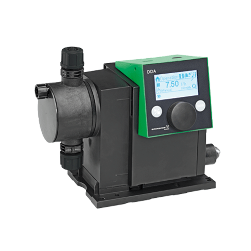
Примечание к изображению: Внимание! Фотография продукта может отличаться от существующего.
Кривая характеристики DDA 12-10
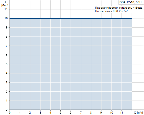
Жидкость DDA 12-10
| Рабочая жидкость | Вода |
| Диапазон температур жидкости | -10 .. 45 °C |
| Темпер. жидкости | 20 °C |
| Плотность | 998.2 кг/м3 |
Материалы DDA 12-10
| Дозирующая головка | PP (полипропилен) |
| Шарик клапана | Керамика |
| Прокладка | EPDM |
| Dosing head | PP (полипропилен) |
Данные электрооборудования DDA 12-10
| Максимальная подводимая мощность — P1 | 24 Вт |
| Промышленная частота | 50 Hz |
| Тип кабельной вилки | EU |
| Пусковой ток | 25A при 230В для 2мсек |
| Максимальная подводимая мощность — P1 | 18 Вт |
| Номинальное напряжение | 1 x 100-240 V |
| Класс защиты (IEC 34-5) | IP65 / NEMA 4X |
| Тип кабельной вилки | SCHUKO |
| Сетевой кабель | 1.5 м |
| Inrush current | 25A при 230В для 2мсек |
Монтаж DDA 12-10
| Диапазон температуры окружающей среды | 0 .. 45 °C |
| Макс. рабочее давление | 10 бар |
| Монтажный набор | НЕТ |
| Тип установки | Без монтажного набора |
| Вход насоса | 4/6, 6/9, 6/12, 9/12 mm |
| Выход насоса | 4/6, 6/9, 6/12, 9/12 mm |
| Макс. высота всасывания во время работы | 6 м |
| Макс. высота всасывания при заливке | 3 м |
| Installation set | НЕТ |
| Installation type | Без монтажного набора |
| Max. Suction lift during operation | 6 м |
| Max. Suction lift during priming | 3 м |
Устр-ва управл-ия DDA 12-10
| Вариант управления | AR |
| Панель управления | монтируется на передней панели |
| Контроль уровня | YES |
| Аналоговый вход | 0/4-20 мА |
| Импульсный выход | ДА |
| Внешний старт/стоп | ДА |
| Аналоговый выход | 0/4-20 мА |
| Аварийное реле | 2 |
| Протокол BUS | ДА |
| Pulse control | ДА |
| Ext. Stop input | ДА |
| Output relays | 2 |
| Bus communication | ДА |
Другое DDA 12-10
| Нетто вес | 3 кг |
| Полный вес | 4 кг |
| ЦВЕТ | GREEN |
Габаритный чертеж DDA 12-10
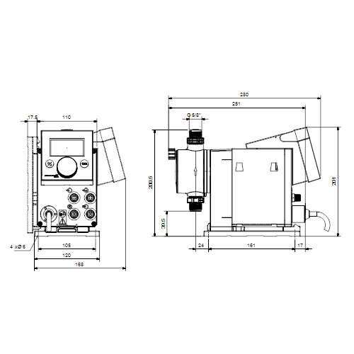
| Примечание | Правовая оговорка |
| Внимание! Все величины даны в [мм], если не указано иное. | На данном упрощённом габаритном чертеже представлены не все компоненты. |
[elementor-template id=»15025″]
Техническое описание:
Grundfos DDA 12-10 AR-PP/E/C-F-31U2U2FG, артикул: 97722040 — это компактный объемный, дозирующий насос с диафрагмой, двигателем с переменной скоростью вращения (двигатель PMS) и интеллектуальной электронной системой управления. Потребляет минимальное количество электроэнергии. Серия SMART Digital Dosing работает с полной длиной хода, чтобы обеспечить оптимальную точность, дозирования и всасывание даже для жидкостей с высокой вязкостью или дегазацией. Продолжительность каждого такта выпуска зависит от установки мощности, что обеспечивает оптимальный плавный и непрерывный расход. Монтажная панель обеспечивает быструю установку и обслуживание. Блок управления можно легко поворачивать в переднее, левое или правое положение. Колесо управления и разноцветная подсветка графического текстового ЖК-дисплей делают ввод в эксплуатацию интуитивно понятным. Элементы управления защищены прозрачной крышкой.
Дозирующая головка состоит из:
- Тефлоновой мембраны, материал которой является универсальным, химически стойким и обеспечивает длительный срок службы.
- Двойных шариковых (всасывающего и нагнетательного) клапанов для устранения перетечек жидкостей и максимальной точности дозирования.
- Клапана деаэрации для удаления воздуха из дозирующей головки в момент пуска, что облегчает запуск насоса.
Режимы работы:
- Ручное дозирование в мл / ч, л / ч или гал.
Импульсное управление в мл / импульс (с функцией памяти)
- Аналоговое управление 0/4-20 мА (масштабируемое).
- Режим работы «Партия» в мл, л или гал.
- Таймер на основе функции «Партия» (дозирование по таймеру, недельным циклом).
- Цифровое управление (GENIbus подготовлены для модулей Grundfos CIU).
- Авто-деаэрация во время работы насоса в режиме ожидания, чтобы избежать аварии из-за воздушных пробок.
- SlowMode (анти-кавитация), позволяет уменьшать частоту вращения двигателя на 50% (maximum flow: 60 л/ч) и 25%(maximum flow: 30 л/ч), например, высокой вязкостью или дегазации жидкостей.
- Дисплей “Сервис” показывает, когда необходимо выполнить техобслуживание изнашиваемых деталей.
- Два варианта блокировки клавиш в зависимости от уровня защиты для защиты насоса от несанкционированного доступа.
- Дополнительная функция для отображения дополнительной информации, например, фактический ввод мА.
- Счетчик для общего дозированного объема (сброс), часы работы и т.д.
- Сохранять и загружать пользовательские настройки, а также изменять заводские настройки.
Сигнальные входы / выходы:
- Вход для импульсов, аналоговый 0 / 4-20 мА и внешний останов.
- Вход для сигнала низкого уровня и пустого резервуара.
- Два беспотенциальных выходных реле для максимального 30 В переменного / постоянного тока (настраиваемый, например, сигнал тревоги, сигнал хода, дозировка насоса, таймер и т. Д.).
- Выходной аналоговый 0 / 4-20 мА.
- Интерфейс связи Fieldbus (GENIbus, для подключения преобразователя fieldbus Grundfos CIU).
См. подробное описание серии
Технические данные:Расшифровка: DDA 12-10 AR-PP/E/C-F-31U2U2FG |
Жидкость:Рабочая жидкость: Вода |
Материалы:Дозирующая головка: PP (полипропилен) |
Данные электрооборудования:Максимальная потребляемая мощность — P1: 24 Вт |
Монтаж:Диапазон температуры окружающей среды: 0 .. 45 °C |
Управление:Вариант управления: AR |
|
|
Другое:Нетто вес: 2 кг |
Гидравлические характеристики:

Габаритные размеры:
Деталировка:
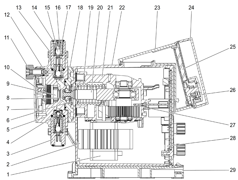
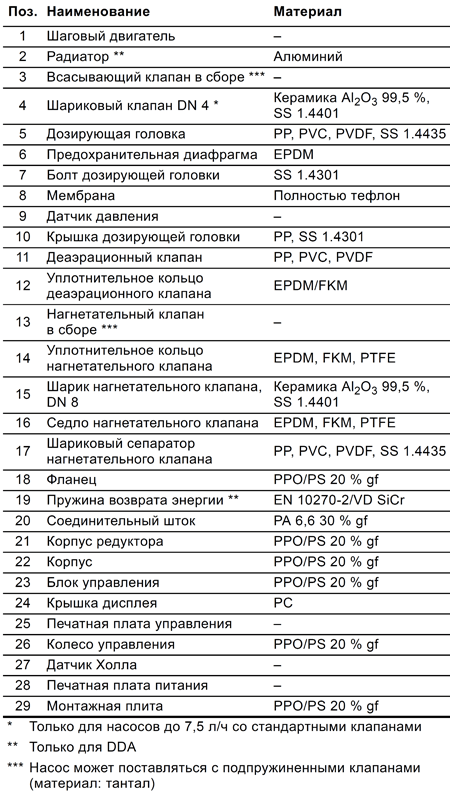
Документация:
[elementor-template id=»59448″]
[elementor-template id=»162759″]