-
Contents
-
Table of Contents
-
Troubleshooting
-
Bookmarks
Quick Links
This user manual describes all items concerning the operation of
the system in detail as much as possible. However, it is impractical to give
particular descriptions of all unnecessary and/or unavailable operations of
the system due to the manual content limit, product specific operations and
other causes. Therefore, the operations not specified herein shall be
considered impossible or unallowable.
This user manual is the property of GSK CNC Equipment Co.,
Ltd. All rights are reserved. It is against the law for any organization or
individual to publish or reprint this manual without the express written
permission of GSK and the latter reserves the right to ascertain their legal
liability.
Summary of Contents for GSK GSK980TDc
Система ЧПУ для токарных станков GSK 980TDb.
Руководство по эксплуатации
Формат: PDF
В данном руководстве по эксплуатации приведена подробная информация об
операциях, выполняемых на системе ЧПУ GSK 980TDb. Однако в нем не содержится
практическое описание ненужных операций и/или операций, выполнение которых
невозможно на системе ЧПУ с данными техническими характеристиками.
Оглавление:
ГЛАВА ПЕРВАЯ ПРОГРАММ�?РОВАН�?Е 15
1.1 Общая информация о системе ЧПУ GSK980TDb 15
1.2 Системы ЧПУ для станков и станки ЧПУ 19
1.3 Основы программирования 21
1.4 Структура управляющей программы 25
1.5 Запуск программы 30
1.6 �?нкрементальная система измерения перемещений по основным осям 31
1.7 �?нкрементальная система измерения перемещений по вспомогательным осям 35
ГЛАВА ВТОРАЯ M,S,T,F КОМАНДЫ 37
2.1 М команды (вспомогательная функция) 37
2.2 Функции шпинделя 41
2.3 Функция инструмента 46
2.4 Функция подачи 60
ГЛАВА ТРЕТЬЯ G КОМАНДЫ 67
3.1 Команды 67
3.2 Быстрое перемещение G00 70
3.3 Линейная интерполяция G01 72
3.4 Круговая интерполяция G02, G03 73
3.5 Дуговая интерполяция из трех координат G05 6
3.6 Эллиптическая интерполяция G6.2, G6.3 77
3.7 Параболическая интерполяция G7.2, G7.3 80
3.8 Функция снятия фасок 83
3.9 Выдержка G04 89
3.10 Функция нулевой точки станка 89
3.11 Пропуск интерполяции G31 93
3.12 Автоматическая коррекция на инструмент G36, G37 95
3.13 Система координат заготовки G50 97
3.14 Команда постоянного цикла 98
3.15 Команды комбинированных циклов 104
3.16 Команды нарезания резьбы резцом 127
3.17 Поддержание постоянной окружной скорости G96, поддержание постоянной
частоты вращения шпинделя G97 141
3.18 Подача за минуту G98, подача за оборот G99 143
3.19. Функция дополнительной оси 144
3.20 Макрокоманды 145
3.21 Операторы макрокоманд 156
3.22 Переключение между метрической и дюймовой системой измерения 160
ГЛАВА ЧЕТВЕРТАЯ КОРРЕКЦ�?Я НА РАД�?УС ЗАКРУГЛЕН�?Я РЕЖУЩЕЙ КРОМК�?
�?НСТРУМЕНТА (G41, G42) 163
4.1 Применение 163
4.2 Траектория коррекции на радиус закругления режущей кромки инструмента 172
КН�?ГА ВТОРАЯ ЭКСПЛУАТАЦ�?Я СЧПУ 185
ГЛАВА 1 РЕЖ�?М РАБОТЫ �? ОП�?САН�?Е ОКОН 186
1.2 Режимы управления 192
ГЛАВА 2 ВКЛЮЧЕН�?Е/ОТКЛЮЧЕН�?Е П�?ТАН�?Я �? ЗАЩ�?ТА 212
2.1 Включение питания СЧПУ 212
2.2 Отключение питания СЧПУ 212
2.3 Защита предела хода 212
2.4 Аварийный режим работы 214
ГЛАВА 3 РУКОВОДСТВО ПО ЭКСПЛУАТАЦ�?�? 215
3.1 Перемещение по оси координат 215
3.2 Другие операции при работе в режиме ручного управления 218
ГЛАВА 4 УПРАВЛЕН�?Е ПОСРЕДСТВОМ ЭЛЕКТРОННОГО ШТУРВАЛА/ПОШАГОВОЕ
УПРАВЛЕН�?Е 220
4.1 Пошаговая подача 220
4.2 Подача посредством электронного штурвала 221
ГЛАВА 5 РЕЖ�?М РУЧНОГО ВВОДА ДАННЫХ (MDI) 224
5.1 Ввод кодовых слов 224
5.2 Выполнение кодовых слов 225
5.3 Установка параметров 225
5.4 �?зменение данных 225
ГЛАВА 6 РЕДАКТ�?РОВАН�?Е ПРОГРАММЫ �? УПРАВЛЕН�?Е ПРОГРАММОЙ 228
6.1 Написание программы 228
6.2 Комментарий к программе 237
6.3 Удаление программы 239
6.5 Выполнение программы 241
6.6 �?зменение имени программы 241
6.7 Копирование программы 241
6.8 Управление программой 241
6.9 Другие операции, доступные в режиме редактирования 242
ГЛАВА 7 КОРРЕКЦ�?Я НА �?НСТРУМЕНТ �? РАЗМЕРНАЯ НАСТРОЙКА 244
7.1 Настройка положения инструмента 244
7.2 Пробная размерная настройка инструмента 245
7.3 Размерная настройка инструмента в нулевой точке программы 247
7.4 Установка и изменение значения коррекции 250
7.4.6 Блокировка и разблокировка значения коррекции 252
ГЛАВА 8 РАБОТА В РЕЖ�?МЕ АВТОМАТ�?ЧЕСКОГО УПРАВЛЕН�?Я 254
8.1 Работа в режиме автоматического управления 254
8.2 Работа в различных режимах 258
8.3 Другие операции 262
ГЛАВА 9 ВОЗВРАТ В НУЛЕВУЮ ТОЧКУ ПРОГРАММЫ 263
9.1 Возврат в нулевую точку программы 263
9.3 Другие операции при возврате в нулевую точку станка 265
ГЛАВА 10 ВВОД, РЕЗЕРВНОЕ КОП�?РОВАН�?Е �? ВОССТАНОВЛЕН�?Е ДАННЫХ 266
10.1 Ввод данных 266
10.3 Установка и изменение пароля 275
10.3.1 Вход в уровень управления 276
ГЛАВА 11 СОВЕРШЕННОЕ УПРАВЛЕН�?Е (ФУНКЦ�?Я
�?СПОЛЬЗОВАН�?Я УСТРОЙСТВА USB) 280
11.1 Путь доступа 280
11.2 Выполнение операций 281
11.3 Примечание 282
ГЛАВА 12 ФУНКЦ�?Я УПРАВЛЕН�?Я ЧЕРЕЗ УСТРОЙСТВО USB 283
12.1 Окно КАТАЛОГ ФАЙЛОВ 283
12.2 Описание обычных операций с файлами 83
ГЛАВА 13 КОММУН�?КАЦ�?Я 285
13.1 Описание коммуникационное программное обеспечение TDComm2a СЧПУ
GSK980TDb 285
13.2 Подготовка перед коммуникацией 294
13.3 Ввод данных (передача данных с ПК на СЧПУ) 295
13.4 Вывод данных (передача данных с СЧПУ на ПК) 300
13.5 Обмен данными между двумя системами ЧПУ 307
ГЛАВА 14 ПР�?МЕРЫ ОБРАБОТК�? 309
14.1 Программирование 310
14.2 Ввод программы 311
14.3 Проверка программ 313
14.4 Размерная настройка инструмента и запуск 314
КН�?ГА ТРЕТЬЯ УСТАНОВКА �? ПОДКЛЮЧЕН�?Е 318
ГЛАВА 1 СХЕМА УСТАНОВК�? 319
1.1 Подключение СЧПУ GSK980TDb 319
1.2 Установка СЧПУ GSK980TDb 320
ГЛАВА 2 ОПРЕДЕЛЕН�?Е �? ПОДКЛЮЧЕН�?Е С�?ГНАЛОВ �?НТЕРФЕЙСА 323
2.1 Подключение к приводу 323
2.2 Подключение СЧПУ к энкодеру шпинделя 327
2.3 Подключение к электронному штурвалу (MPG) 328
2.4 �?нтерфейс шпинделя 329
2.5 Подключение СЧПУ GSK980TDb к ПК 330
2.6 Подключение интерфейса питания 331
2.7 Описание интерфейса ввода/вывода 332
2.8 Функция ввода/вывода и подключение 338
2.9 Общеупотребительные обозначения на электрических схемах 368
ГЛАВА 3 ПАРАМЕТРЫ 370
3.1 Описание параметра (последовательное) 370
3.1.1 Битовый параметр 370
3.2 Описание параметров (последовательность функций) 401
ГЛАВА 4 СПОСОБЫ �? РЕЖ�?МЫ НАСТРОЙК�? СТАНКА 425
4.1 Аварийный останов и пределы хода 425
4.2 Конфигурация привода 425
4.3 Настройка передаточного числа 426
4.4 Настройка характеристик разгона/торможения 426
4.5 Механическая настройка нулевой точки станка 427
4.6 Настройка шпинделя 429
4.7 Коррекция люфтов 430
4.8 Настройка резцедержателя 431
4.9 Настройка пошагового режима/режима управления посредством электронного штурвала 431
4.10 Другие настройки 431
ГЛАВА 5 СООБЩЕН�?Я Д�?АГНОСТ�?К�? 434
5.1 Диагностика СЧПУ 434
5.2 Состояние ПЛК 436
5.3 Данные ПЛК 451
ГЛАВА 6 СОХРАНЕН�?Е ЗНАЧЕН�?Я КОМПЕНСАЦ�?�? ПОГРЕШНОСТ�? ШАГА 454
6.1 Описание функции 454
6.2 Характеристики 454
6.3 Установка параметров 454
6.4 Примечания по установке компенсации 455
6.5 Примеры установки параметров компенсации погрешности шага 455
Приложение 459
Приложение 1 Установочный чертеж СЧПУ GSK980TDb 460
Приложение 2 Габаритные размеры СЧПУ GSK980TDb-В 461
Приложение 3 Габаритные размеры съемной панели AP01 461
Приложение 4 Габаритные размеры съемной панели AP02 462
Приложение 5 Габаритные размеры съемной панели AP03 462
Приложение 6 Габаритные размеры счетчика входных/выходных импульсов
MCT01A 463
Приложение 7 Внешние габариты счетчика входных/выходных импульсов MCT02 463
Приложение 8 Перечень стандартных параметров 464
Приложение 9 Перечень предупредительных сообщений 470
Приложение 10 Перечень операций 476
ВН�?МАН�?Е!
Вся информация, которая размещается на сайте носит ознакомительный характер. Мы стремимся к тому, чтобы Вы получали только достоверную, максимально полную и точную информацию. Но мы не исключаем, что некоторая информация может со временем утратить свою актуальность, допускаем возможность ошибок в содержании.
�?нформация на сайте размещается в исходном виде. Мы не даем гарантии на полноту и актуальность информации. �?нформация предоставляется также без каких-либо других явно или неявно выраженных или предполагаемых гарантий.
Администрация сайта оставляет за собой право, не уведомляя пользователей и посетителей ресурса, вносить изменения в контент.
Администрация сайта не несет ответственности за информацию, предоставленную пользователями.
На сайте есть ссылки на сторонние ресурсы (сайты), на которые мы не имеем никакого влияния. Ссылки на другие ресурсы предназначены для того, чтобы пользователю было удобнее искать информацию по схожей тематике. Мы не несем ответственности за содержание других сайтов (контент), за их доступность пользователям.
Нет и не может быть таких обстоятельств, при которых владелец (администрация) сайта будет нести какую-либо ответственность перед какой-либо стороной за прямой, непрямой или косвенно причиненный ущерб из-за использования информации, находящейся на страницах этого сайта, или информации на том сайте, на который имеется гиперссылка с этого ресурса. Ни при каких обстоятельствах мы не будем нести ответственность за возможную, но упущенную выгоду, потерю программ или данных, приостановку вашей хозяйственной деятельности и в аналогичных случаях, даже если будем явно проинформированы о большой вероятности подобного ущерба.
�?нтернет не обеспечивает надежной защиты данных и информации, поэтому не несет и не может нести ответственность за информацию, которую получают пользователи из �?нтернета.
Посещая данный сайт и используя его контент в своих целях, Вы прямо выражаете свое согласие с данным «Отказом от ответственности» и принимаете всю ответственность на себя.
Администрация сайта в любое время может и имеет право вносить изменения в эти правила. Они вступают в силу безотлагательно с этого момента. Если Вы продолжаете пользоваться сайтом после того, как в «Отказ от ответственности» внесены изменения, значит — Вы автоматически согласились на соблюдение обновленных правил.
Владельцы и создатели данного ресурса не несут ответственности за содержание ссылок, за их использование и за информацию, размещенную на данном сайте, как не несут ответственность за игнорирование пользователями коммерческого статуса того программного обеспечения, на которое ведут ссылки с этого сайта.
Авторское право и право на товарный знак
Мы стремимся соблюдать авторские права других собственников и использовать собственные или не требующие лицензирования материалы. Загрузка и копирование текстовых материалов, изображений, фотографий или иных файлов с нашего сайта допускается только для личного, некоммерческого использования. Поскольку содержимое этого раздела сайта создается из открытых общедоступных и бесплатных источников. Если вам стало известно об авторском праве на какой-либо материал на сайте, пожалуйста, сообщите нам. После уведомления о нарушениях, мы удалим такое содержимое немедленно.
![]()
Российский станкостроительный завод
Системы чпу GSK
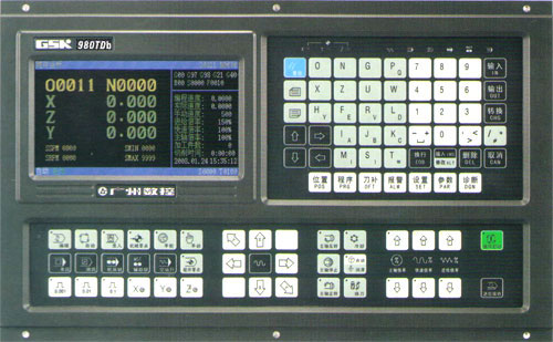

GSK980TDb преставляет из себя систему ЧПУ для токарных станков нового поколения с программируемой системой FPGA. Система позволяет управлять широким спектром задач в режиме реального времени и интерполирование заготовок, что позволяет обрабатывать детали с высокой точностью. Цветной жидкокристаллический дисплей отображает информацию в высоком разрешении на английском, китайском, испанском и русском языках. Вы можете купить системы чпу GSK со склада и под заказ.
-
Характеристики
- Контролируемые оси (X, Y, Z), управляемые оси (X, Z), точное вычисление на микро уровне, а так же максимальная скорость при быстром ходе 60 м/мин, возможность производить линейную, параболическую, дуговую, эллиптическую интерполяцию;
- Шаг перемещений 0,001 мм, регулирование по умножению и делению 1…32767;
- Коррекция погрешности шага, коррекция длины инструмента, компенсация люфтов, пространственная поправка на длину инструмента, а так же поправка на радиус инструмента;
- Встроенная система PLC позволяет производить загрузку, передачу и редактирование многоступенчатых схем;
- Реализация экспоненциальной функции замедления или ускорения для максимальной точности обработки;
- Возможность нарезания метрической и дюймовой однозаходной и многозаходной резьбы, упорной резьбы, конической резьбы, различных видов ходовой резьбы. Высокая скорость нарезания резьб с заданными параметрами угла, выхода и скорости;
- Возможность программирования как в дюймах, так и в мм, автоматическое выполнение фаски, управление магазином с инструментами;
- Программирование макро командами, возможность вызова макро команд с параметрами;
- Цветной дисплей выводит информацию на английском, китайском, испанском и русском языках;
- Большой объём памяти 6144КВ позволяет хранить 384 программы обработки деталей;
- Лёгкое управление системой ЧПУ с использованием многоуровневого эксплуатационного кода;
- Двусторонняя связь между ЧПУ и ПК, модернизированное програмное обеспечение PLC.
Представительства в регионах


 This user manual describes all items concerning the operation of the system in detail as much as possible. However, it is impractical to give
particular descriptions of all unnecessary and/or unavailable operations of
the system due to the manual content limit, product specific operations and
other causes. Therefore, the operations not specified herein shall be
considered impossible or unallowable.
 This user manual is the property of GSK CNC Equipment Co., Ltd. All rights are reserved. It is against the law for any organization or
individual to publish or reprint this manual without the express written
permission of GSK and the latter reserves the right to ascertain their legal
liability.

GSK980TDb Turning CNC System User Manual
FOREWORD
Dear user,
We are really grateful for your patronage and purchase of this GSK980TDb Turning CNC system made by GSK CNC Equipment Co., Ltd.
The user manual describes the programming, operation, installation and connection of this GSK980TDb Turning CNC system. Please read it carefully before operation in order to get the safe and effective working.
Warning
 This system can only be operated by authorized and qualified personnel as improper operations may cause accidents.
Please carefully read this user manual before use!
Note: The power supply installed on (in) the cabinet is exclusive to GSK’S CNC systems.
The power supply form is forbidden to be used for other purposes. Otherwise, there may be extreme danger!
This user manual shall be kept by final user.
II

Notes
Notes
■ Delivery and storage
zPacking box over 6 layers in pile is unallowed.
zNever climb the packing box, neither stand on it, nor place heavy objects on it.
zDo not move or drag the product by the cables connected with it.
zForbid collision or scratch to the panel and displayer.
zPacking box should be protected from damping, insolation and raining.
■Open packing box to check
zEnsure things in packing box are the required ones.
zEnsure the product is not damaged in delivery.
zEnsure the parts in packing box are in accordance to the order.
zContact us in time if the product type is inconsistent with the order, there is short of accessories, or product damage in delivery.
■Connection
zOnly qualified persons can connect the system or check the connection.
zThe system must be earthed, its resistance must be less than 4 Ω and the ground wire cannot be replaced by zero wire.
zConnection must be correct and firm to avoid the product to be damaged or other unexpected result.
zConnect with surge diode in the specified direction to avoid the damage to the system.
zSwitch off power supply before pulling out plug or opening electric cabinet.
■Troubleshooting
zSwitch off power supply before troubleshooting or changing components.
zTroubleshoot and then startup the system when there is short circuit or overload.
zDo not switch on or off it frequently and an interval is 1 minute at least after the system is powered on again.
III

GSK980TDb Turning CNC System User Manual
Announcement
zThis manual describes various items as much as possible. However, operations allowable or unallowable cann’t be explained one by one due to so many possibilities that may involve with, so the contents that are not specially stated in this manual shall be considered to be unavailable.
Warning
zPlease read this user manual and a manual from machine builder completely before installation, programming and operation; do operate the system and machine according to user manuals, otherwise it may damage the system, machine, workpiece and even injure the operator.
Cautions
z Functions, technical indexes described in this user manual are only for the system. Actual functions and technical performance of machine tool with this CNC system are determined by machine builder’s design, so refer to its user manual.
zThe system is employed with integrated machine control panel and the keys on machine control panel are defined by PLC program. Functions of keys in this user manual are for standard PLC program. Please notice it!
zRefer to user manual from machine manufacturer about functions and meanings of keys on machine control panel.
All specification and designs are subject to change without further notice.
IV

Summary
Volume Programming
GSK980TDb CNC Technical Specification, Product
Type, Command and Program Format
Volume Operation
GSK980TDb CNC Operation Use
Volume Installation and Connection
GSK980TDb CNC Installation, Connection and Setting
Appendix
CNC Ladder Function Allocation, Alarm Message Table
V

GSK980TDb Turning CNC System User Manual
Safety Responsibility
Manufacturer’s safety responsibility
——The manufacturer should be responsible for the cleared or the controlled safety in the design and the structure of the CNC system and the accessories.
——The manufacturer should be responsible for the CNC system and the accessories. ——The manufacturer should be responsible for the message and the suggestion for the user.
User’s safety responsibility
——The user should study and train the system safety operation, master the safety operation content.
——The user should be responsible for the danger caused by increasing, changing or modifying the CNC system, the accessories by itself.
——The user should be responsible for the danger because of the mistaken operation, regulation, maintenance, installation and storage.
VI
|
Contents |
||||||
|
CONTENTS |
||||||
|
Volume Programming |
||||||
|
CHAPTER 1 |
PROGRAMMING …………………………………………………………………………………………… |
3 |
||||
|
1.1 |
GSK980TDb introduction ……………………………………………………………………………………….. |
3 |
||||
|
1.1.1 |
Product introduction……………………………………………………………………………………… |
3 |
||||
|
1.1.2 |
Technical specification ………………………………………………………………………………….. |
4 |
||||
|
1.1.3 |
Environment and conditions…………………………………………………………………………… |
6 |
||||
|
1.1.4 |
Power supply ………………………………………………………………………………………………. |
7 |
||||
|
1.1.5 |
Guard…………………………………………………………………………………………………………. |
7 |
||||
|
1.2 CNC system of machine tools and CNC machine tools ………………………………………………. |
7 |
|||||
|
1.3 |
Programming fundamentals……………………………………………………………………………………. |
9 |
||||
|
1.3.1 |
Coordinates definition …………………………………………………………………………………… |
9 |
||||
|
1.3.2 Machine coordinate system, Machine Zero and machine reference point …………….. |
9 |
|||||
|
1.3.3 Workpiece coordinate system and Program Zero……………………………………………. |
10 |
|||||
|
1.3.4 |
Interpolation function ………………………………………………………………………………….. |
11 |
||||
|
1.3.5 Absolute programming and incremental programming …………………………………….. |
12 |
|||||
|
1.3.6 Diameter programming and radius programming ……………………………………………. |
12 |
|||||
|
1.4 Structure of an NC program ………………………………………………………………………………….. |
13 |
|||||
|
1.4.1 General structure of a program…………………………………………………………………….. |
14 |
|||||
|
1.4.2 Main program and subprogram…………………………………………………………………….. |
17 |
|||||
|
1.5 |
Program run……………………………………………………………………………………………………….. |
18 |
||||
|
1.5.1 Sequence of program run ……………………………………………………………………………. |
18 |
|||||
|
1.5.2 Execution sequence of word………………………………………………………………………… |
19 |
|||||
|
1.6 Basic axis incremental system………………………………………………………………………………. |
19 |
|||||
|
1.6.1 Incremental system speed of basic axis ………………………………………………………… |
19 |
|||||
|
1.6.2 Incremental system unit of basic axis ……………………………………………………………. |
20 |
|||||
|
1.6.3 Incremental system data range of basic axis ………………………………………………….. |
20 |
|||||
|
1.6.4 Incremental system data range and unit of basic axis ……………………………………… |
21 |
|||||
|
1.6.5 Program address value unit and range of incremental system of basic axis………… |
22 |
|||||
|
1.7 Additional axis incremental system ………………………………………………………………………… |
23 |
|||||
|
1.7.1 Additional axis being the current incremental system ………………………………………. |
24 |
|||||
|
1.7.2 Additional axis being IS-A incremental system ……………………………………………….. |
24 |
|||||
|
CHAPTER 2 |
MSTF COMMAND |
……………………………………………………………………………………….. |
25 |
|||
|
2.1 |
M (miscellaneous function) …………………………………………………………………………………… |
25 |
||||
|
2.1.1 |
End of program |
M02 ………………………………………………………………………………… |
25 |
|||
|
2.1.2 |
End of program run |
M30 …………………………………………………………………………… |
25 |
|||
|
2.1.3 |
Subprogram call |
M98 ……………………………………………………………………………….. |
26 |
|||
|
2.1.4 |
Return from subprogram M99 ……………………………………………………………………. |
26 |
||||
|
2.1.5 |
Macro program call |
M9000 M9999 …………………………………………………………… |
27 |
|||
|
2.1.6 M commands defined by standard PLC ladder diagram …………………………………… |
27 |
|||||
|
2.1.7 |
Program stop M00……………………………………………………………………………………. |
28 |
||||
|
2.1.8 Program optional stop M01………………………………………………………………………….. |
28 |
|||||
|
2.1.9 Spindle CW, CCW and stop control M03, M04, M05 ……………………………………….. |
29 |
|||||
|
2.1.10 |
Cooling control |
M08, M09 ……………………………………………………………………….. |
29 |
|||
|
2.1.11 |
Tailstock control |
M10, M11 ………………………………………………………………………. |
29 |
|||
|
2.1.12 |
Chuck control |
M12, M13 …………………………………………………………………………. |
29 |
VII

GSK980TDb Turning CNC System User Manual
|
2.1.13 Spindle position/speed control switch M14, M15 …………………………………………… |
29 |
|||||||
|
2.1.14 Spindle clamped/released M20, M21…………………………………………………………… |
30 |
|||||||
|
2.1.15 |
The 2nd spindle position/speed switch |
M24, M25………………………………………… |
30 |
|||||
|
2.1.16 Lubricating control M32, M33 …………………………………………………………………….. |
30 |
|||||||
|
2.1.17 Spindle automatic gear change M41, M42, M43, M44……………………………………. |
30 |
|||||||
|
2.1.18 Spindle 8-point orientation M50 M58…………………………………………………………. |
30 |
|||||||
|
2.1.19 The 2nd spindle rotation CCW, rotation CW , stop M63, M64, M65…………………… |
31 |
|||||||
|
2.2 |
Spindle function ………………………………………………………………………………………………….. |
31 |
||||||
|
2.2.1 Spindle speed switching value control …………………………………………………………… |
31 |
|||||||
|
2.2.2 Spindle speed analog voltage control ……………………………………………………………. |
32 |
|||||||
|
2.2.3 Constant surface speed control G96, constant rotational speed control G97 ………. |
32 |
|||||||
|
2.2.4 |
Spindle override…………………………………………………………………………………………. |
35 |
||||||
|
2.2.5 Multiple spindle control function……………………………………………………………………. |
35 |
|||||||
|
2.2.6 Cs contour control funciton………………………………………………………………………….. |
36 |
|||||||
|
2.3 |
Tool function ………………………………………………………………………………………………………. |
36 |
||||||
|
2.3.1 |
Tool control ……………………………………………………………………………………………….. |
36 |
||||||
|
2.3.2 |
Tool life management …………………………………………………………………………………. |
40 |
||||||
|
CHAPTER 3 G COMMANDS |
……………………………………………………………………………………………. |
50 |
||||||
|
3.1 |
Commands ………………………………………………………………………………………………………… |
50 |
||||||
|
3.1.1 Modal, non-modal and initial mode……………………………………………………………….. |
51 |
|||||||
|
3.1.2 |
Omitting words…………………………………………………………………………………………… |
51 |
||||||
|
3.1.3 |
Related definitions ……………………………………………………………………………………… |
53 |
||||||
|
3.2 |
Rapid traverse movement |
G00 …………………………………………………………………………… |
53 |
|||||
|
3.3 |
Linear interpolation |
G01…………………………………………………………………………………….. |
54 |
|||||
|
3.4 |
Circular interpolation |
G02, G03…………………………………………………………………………… |
56 |
|||||
|
3.5 |
Three-point circular interpolation |
G05 ………………………………………………………………….. |
59 |
|||||
|
3.6 |
Ellipse interpolation |
G6.2, G6.3…………………………………………………………………………… |
60 |
|||||
|
3.7 |
Parabola interpolation |
G7.2, G7.3……………………………………………………………………….. |
63 |
|||||
|
3.8 |
Plane selection G17 G19 …………………………………………………………………………………… |
65 |
||||||
|
3.9 |
Polar coordinate interpolation G12.1, G13.1……………………………………………………………. |
66 |
||||||
|
3.10 |
Cylindrical interpolation G7.1………………………………………………………………………………. |
69 |
||||||
|
3.11 |
Chamfering function…………………………………………………………………………………………… |
72 |
||||||
|
3.11.1 |
Linear chamfering…………………………………………………………………………………….. |
72 |
||||||
|
3.11.2 |
Circular chamfering…………………………………………………………………………………… |
74 |
||||||
|
3.11.3 |
Special cases…………………………………………………………………………………………… |
76 |
||||||
|
3.12 |
Dwell G04………………………………………………………………………………………………………. |
78 |
||||||
|
3.13 |
Machine Zero function |
……………………………………………………………………………………….. |
78 |
|||||
|
3.13.1 |
Machine 1st reference point G28 ……………………………………………………………… |
78 |
||||||
|
3.13.2 |
Machine 2nd, 3rd, 4th reference point |
G30………………………………………………… |
79 |
|||||
|
3.14 |
Skip interpolation |
G31……………………………………………………………………………………… |
81 |
|||||
|
3.15 |
Automatic tool offset |
G36, G37 …………………………………………………………………………. |
83 |
|||||
|
3.16 |
Workpiece coordinate system |
G50 ……………………………………………………………………. |
86 |
|||||
|
3.17 |
Fixed cycle command ………………………………………………………………………………………… |
87 |
||||||
|
3.17.1 |
Axial cutting cycle |
G90……………………………………………………………………………. |
87 |
|||||
|
3.17.2 |
Radial cutting cycle |
G94 …………………………………………………………………………. |
90 |
|||||
|
3.17.3 Caution of fixed cycle commands ……………………………………………………………….. |
92 |
|||||||
|
3.18 |
Multiple cycle commands……………………………………………………………………………………. |
93 |
||||||
|
3.18.1 Axial roughing cycle G71…………………………………………………………………………… |
93 |
VIII
|
Contents |
||||
|
3.18.2 Radial roughing cycle G72…………………………………………………………………………. |
99 |
|||
|
3.18.3 |
Closed cutting cycle G73……………………………………………………………………….. |
103 |
||
|
3.18.4 |
Finishing cycle G70 ………………………………………………………………………………… |
107 |
||
|
3.18.5 |
Axial grooving multiple cycle G74 …………………………………………………………… |
108 |
||
|
3.18.6 Radial grooving multiple cycle G75……………………………………………………………. |
111 |
|||
|
3.19 |
Thread cutting commands ………………………………………………………………………………… |
114 |
||
|
3.19.1 Thread cutting with constant lead G32……………………………………………………….. |
115 |
|||
|
3.19.2 Rigid thread cutting G32.1 ……………………………………………………………………….. |
117 |
|||
|
3.19.3 |
Thread cutting with variable lead |
G34……………………………………………………… |
119 |
|
|
3.19.4 |
Z thread cutting G33 …………………………………………………………………………….. |
121 |
||
|
3.19.5 Rigid tapping G84, G88 …………………………………………………………………………… |
122 |
|||
|
3.19.6 Thread cutting cycle G92…………………………………………………………………………. |
125 |
|||
|
3.19.7 Multiple thread cutting cycle G76………………………………………………………………. |
128 |
|||
|
3.20 |
Constant surface speed control G96, constant rotational speed control G97 ……….. |
132 |
||
|
3.21 Feedrate per minute G98, feedrate per rev G99…………………………………………………… |
132 |
|||
|
3.22. |
Additional Axis Function…………………………………………………………………………………… |
134 |
||
|
3.22.1 |
Additional axis start…………………………………………………………………………………. |
134 |
||
|
3.22.2 Motion of additional axis ………………………………………………………………………….. |
134 |
|||
|
3.22.3 Additional axis coordinates display ……………………………………………………………. |
135 |
|||
|
3.23 |
Macro commands ……………………………………………………………………………………………. |
135 |
||
|
3.23.1 |
MACRO variables …………………………………………………………………………………… |
135 |
||
|
3.23.2 |
Operation and jump command |
G65 ………………………………………………………… |
140 |
|
|
3.23.3 Program example with macro command ……………………………………………………. |
143 |
|||
|
3.24 |
Statement macro command ………………………………………………………………………………. |
145 |
||
|
3.24.1 Arithmetic and logic operation…………………………………………………………………… |
145 |
|||
|
3.24.2 |
Transfer and cycle ………………………………………………………………………………….. |
147 |
||
|
3.25 |
Metric/Inch Switch……………………………………………………………………………………………. |
149 |
||
|
3.25.1 |
Functional summary ……………………………………………………………………………….. |
149 |
||
|
3.25.2 |
Function command G20/G21……………………………………………………………………. |
150 |
||
|
3.25.3 |
Notes ……………………………………………………………………………………………………. |
150 |
||
|
CHAPTER 4 TOOL NOSE RADIUS COMPENSATION (G41, G42) ……………………………………… |
151 |
|||
|
4.1 |
Application ……………………………………………………………………………………………………….. |
151 |
||
|
4.1.1 |
Overview…………………………………………………………………………………………………. |
151 |
||
|
4.1.2 Imaginary tool nose direction……………………………………………………………………… |
152 |
|||
|
4.1.3 |
Compensation value setting……………………………………………………………………….. |
155 |
||
|
4.1.4 |
Command format ……………………………………………………………………………………… |
156 |
||
|
4.1.5 |
Compensation direction …………………………………………………………………………….. |
156 |
||
|
4.1.6 |
Notes ……………………………………………………………………………………………………… |
158 |
||
|
4.1.7 |
Application ………………………………………………………………………………………………. |
159 |
||
|
4.2 Tool nose radius compensation offset path……………………………………………………………. |
160 |
|||
|
4.2.1 Inner and outer side………………………………………………………………………………….. |
160 |
|||
|
4.2.2 Tool traversing when starting tool ……………………………………………………………….. |
160 |
|||
|
4.2.3 Tool traversing in Offset mode ……………………………………………………………………. |
162 |
|||
|
4.2.4 Tool traversing in Offset canceling mode ……………………………………………………… |
167 |
|||
|
4.2.5 |
Tool interference check……………………………………………………………………………… |
168 |
||
|
4.2.6 Commands for canceling compensation vector temporarily ……………………………. |
170 |
|||
|
4.2.7 |
Particulars……………………………………………………………………………………………….. |
172 |
IX
![]()
GSK980TDb Turning CNC System User Manual
Volume Operation
|
CHAPTER 1 OPERATION MODE AND DISPLAY INTERFACE …………………………………………… |
175 |
||
|
1.1 |
Panel division……………………………………………………………………………………………………. |
175 |
|
|
1.1.1 |
State indication ………………………………………………………………………………………… |
176 |
|
|
1.1.2 |
Edit keypad……………………………………………………………………………………………… |
176 |
|
|
1.1.3 |
Menu display …………………………………………………………………………………………… |
177 |
|
|
1.1.4 |
Machine panel …………………………………………………………………………………………. |
177 |
|
|
1.2 |
Summary of operation mode ………………………………………………………………………………. |
180 |
|
|
1.3 |
Display interface ……………………………………………………………………………………………….. |
181 |
|
|
1.3.1 |
POS interface ………………………………………………………………………………………….. |
183 |
|
|
1.3.2 |
PRG interface ………………………………………………………………………………………….. |
186 |
|
|
1.3.3 TOOL OFFSET&WEAR, MACRO, TOOL-LIFE MANAGEMENT interfaces ………. |
188 |
||
|
1.3.4 |
ALARM interface ……………………………………………………………………………………… |
190 |
|
|
1.3.5 |
Setting interface……………………………………………………………………………………….. |
191 |
|
|
1.3.6 BIT PARAMETER, DATA PARAMETER, SCREW-PITCH COMP interfaces ……… |
194 |
1.3.7CNC DIAGNOSIS, PLC STATE, PLC VALUE, TOOL PANEL, VERSION MESSAGE
|
interfaces ………………………………………………………………………………………………………….. |
195 |
||
|
CHAPTER 2 POWER ON/OFF AND PROTECTION………………………………………………………….. |
199 |
||
|
2.1 |
System power on ………………………………………………………………………………………………. |
199 |
|
|
2.2 |
System power off ………………………………………………………………………………………………. |
199 |
|
|
2.3 |
Overtravel protection …………………………………………………………………………………………. |
199 |
|
|
2.3.1 |
Hardware overtravel protection…………………………………………………………………… |
200 |
|
|
2.3.2 |
Software Overtravel Protection…………………………………………………………………… |
200 |
|
|
2.4 |
Emergency operation…………………………………………………………………………………………. |
201 |
|
|
2.4.1 |
Reset ……………………………………………………………………………………………………… |
201 |
|
|
2.4.2 |
Emergency stop……………………………………………………………………………………….. |
201 |
|
|
2.4.3 |
Feed hold………………………………………………………………………………………………… |
201 |
|
|
2.4.4 |
Power-off ………………………………………………………………………………………………… |
201 |
|
|
CHAPTER 3 |
MANUAL OPERATION ……………………………………………………………………………….. |
202 |
|
|
3.1 |
Coordinate axis move ………………………………………………………………………………………… |
202 |
|
|
3.1.1 |
Manual feed…………………………………………………………………………………………….. |
202 |
|
|
3.1.2 |
Manual rapid traverse……………………………………………………………………………….. |
203 |
|
|
3.1.3 |
Speed tune ……………………………………………………………………………………………… |
203 |
|
|
3.2 |
Other manual operations ……………………………………………………………………………………. |
204 |
|
|
3.2.1 Spindle CCW, CW, stop control ………………………………………………………………….. |
204 |
||
|
3.2.2 |
Spindle jog ………………………………………………………………………………………………. |
204 |
|
|
3.2.3 |
Cooling control…………………………………………………………………………………………. |
205 |
|
|
3.2.4 |
Lubricating control ……………………………………………………………………………………. |
205 |
|
|
3.2.5 |
Chuck control…………………………………………………………………………………………… |
206 |
|
|
3.2.6 |
Tailstock control ……………………………………………………………………………………….. |
206 |
|
|
3.2.7 |
Hydraulic control………………………………………………………………………………………. |
206 |
|
|
3.2.8 |
Manual tool change ………………………………………………………………………………….. |
207 |
|
|
3.2.9 |
Spindle override……………………………………………………………………………………….. |
207 |
X
|
Contents |
|||
|
CHAPTER 4 |
MPG/STEP OPERATION…………………………………………………………………………….. |
208 |
|
|
4.1 |
Step feed………………………………………………………………………………………………………….. |
208 |
|
|
4.1.1 |
Increment selection…………………………………………………………………………………… |
208 |
|
|
4.1.2 |
Moving direction selection …………………………………………………………………………. |
209 |
|
|
4.2 |
MPG(handwheel) feed ……………………………………………………………………………………….. |
209 |
|
|
4.2.1 |
Increment selection…………………………………………………………………………………… |
209 |
|
|
4.2.2 Moving axis and direction selection …………………………………………………………….. |
210 |
||
|
4.2.3 |
Other operations ………………………………………………………………………………………. |
210 |
|
|
4.2.4 |
Explanation items …………………………………………………………………………………….. |
211 |
|
|
CHAPTER 5 |
MDI OPERATION ………………………………………………………………………………………. |
212 |
|
|
5.1 |
Code words input………………………………………………………………………………………………. |
212 |
|
|
5.2 |
Code words execution ……………………………………………………………………………………….. |
213 |
|
|
5.3 |
Parameter setting………………………………………………………………………………………………. |
213 |
|
|
5.4 |
Data alteration…………………………………………………………………………………………………… |
213 |
|
|
5.5 |
Other operations ……………………………………………………………………………………………….. |
214 |
|
|
CHAPTER 6 PROGRAM EDIT AND MANAGEMENT ………………………………………………………… |
215 |
||
|
6.1 |
Program creation ………………………………………………………………………………………………. |
215 |
|
|
6.1.1 Creating a block number……………………………………………………………………………. |
215 |
||
|
6.1.2 |
Inputting a program…………………………………………………………………………………… |
215 |
|
|
6.1.3 |
Searching a character……………………………………………………………………………….. |
216 |
|
|
6.1.4 |
Inserting a character …………………………………………………………………………………. |
218 |
|
|
6.1.5 |
Deleting a character………………………………………………………………………………….. |
219 |
|
|
6.1.6 |
Altering a character…………………………………………………………………………………… |
219 |
|
|
6.1.7 Deleting a single block………………………………………………………………………………. |
220 |
||
|
6.1.8 |
Deleting blocks ………………………………………………………………………………………… |
220 |
|
|
6.1.9 |
Deleting a segment…………………………………………………………………………………… |
221 |
|
|
6.1.10 Macro program edit…………………………………………………………………………………. |
222 |
||
|
6.2 |
Program annotation …………………………………………………………………………………………… |
222 |
|
|
6.2.1 Creating a program annotation …………………………………………………………………… |
222 |
||
|
6.2.2 Altering a program annotation…………………………………………………………………….. |
224 |
||
|
6.3 |
Deleting program ………………………………………………………………………………………………. |
224 |
|
|
6.3.1 |
Deleting a program …………………………………………………………………………………… |
224 |
|
|
6.3.2 |
Deleting all programs………………………………………………………………………………… |
224 |
|
|
6.3.3 Initiation of program area…………………………………………………………………………… |
224 |
||
|
6.4 |
Selecting a program…………………………………………………………………………………………… |
224 |
|
|
6.4.1 |
Search ……………………………………………………………………………………………………. |
224 |
|
|
6.4.2 |
Scanning…………………………………………………………………………………………………. |
225 |
|
|
6.4.3 |
Cursor…………………………………………………………………………………………………….. |
225 |
|
|
6.5 |
Execution of the program……………………………………………………………………………………. |
226 |
|
|
6.6 |
Renaming a program …………………………………………………………………………………………. |
226 |
|
|
6.7 |
Copy a program ………………………………………………………………………………………………… |
226 |
|
|
6.8 |
Program management ……………………………………………………………………………………….. |
226 |
|
|
6.8.1 |
Program list……………………………………………………………………………………………… |
226 |
|
|
6.8.2 |
Part-Prg number ………………………………………………………………………………………. |
226 |
|
|
6.8.3 Memory size and used capacity………………………………………………………………….. |
227 |
XI

|
GSK980TDb Turning CNC System |
User Manual |
||
|
6.9 |
Other operations available in Edit mode ……………………………………………………………….. |
227 |
|
|
CHAPTER 7 TOOL OFFSET AND SETTING ……………………………………………………………………. |
228 |
||
|
7.1 |
Tool positioning setting ………………………………………………………………………………………. |
228 |
|
|
7.2 |
Trial toolsetting …………………………………………………………………………………………………. |
229 |
|
|
7.3 |
Toolsetting by machine zero return ………………………………………………………………………. |
230 |
|
|
7.4 |
Setting and altering the offset value……………………………………………………………………… |
232 |
|
|
7.4.1 |
Offset setting …………………………………………………………………………………………… |
233 |
|
|
7.4.2 |
Offset alteration ……………………………………………………………………………………….. |
234 |
|
|
7.4.3 Offset alteration in communication mode……………………………………………………… |
234 |
||
|
7.4.4 Clearing the offset values ………………………………………………………………………….. |
235 |
||
|
7.4.5 Setting and altering the tool wear ……………………………………………………………….. |
235 |
||
|
7.4.6 Locking and unlocking the offset value ………………………………………………………… |
235 |
||
|
7.4.7 No.0 tool offset moving workpiece coordinate system……………………………………. |
236 |
||
|
CHAPTER 8 AUTO OPERATION ……………………………………………………………………………………. |
238 |
||
|
8.1 |
Automatic run……………………………………………………………………………………………………. |
238 |
|
|
8.1.1 Selection of the program to be run ……………………………………………………………… |
238 |
||
|
8.1.2 Start of the automatic run…………………………………………………………………………… |
239 |
||
|
8.1.3 Stop of the automatic run…………………………………………………………………………… |
239 |
||
|
8.1.4 Automatic run from an arbitrary block………………………………………………………….. |
240 |
||
|
8.1.5 Adjustment of the feedrate, rapid rate …………………………………………………………. |
240 |
||
|
8.1.6 |
Spindle speed adjustment………………………………………………………………………….. |
241 |
|
|
8.2 |
Running state……………………………………………………………………………………………………. |
241 |
|
|
8.2.1 |
Single block execution………………………………………………………………………………. |
241 |
|
|
8.2.2 |
Dry run……………………………………………………………………………………………………. |
242 |
|
|
8.2.3 |
Machine lock……………………………………………………………………………………………. |
243 |
|
|
8.2.4 |
MST lock…………………………………………………………………………………………………. |
244 |
|
|
8.2.5 |
Block skip ……………………………………………………………………………………………….. |
244 |
|
|
8.3 |
Other operations ……………………………………………………………………………………………….. |
245 |
|
|
CHAPTER 9 ZERO RETURN OPERATION ……………………………………………………………………… |
246 |
||
|
9.1 |
Program zero return…………………………………………………………………………………………… |
246 |
|
|
9.1.1 |
Program Zero ………………………………………………………………………………………….. |
246 |
|
|
9.1.2 Program zero return steps …………………………………………………………………………. |
246 |
||
|
9.2 |
Machine Zero return ………………………………………………………………………………………….. |
247 |
|
|
9.2.1 Machine Zero (machine reference point)……………………………………………………… |
247 |
||
|
9.2.2 Machine Zero return steps…………………………………………………………………………. |
247 |
||
|
9.3 |
Other operations in zero return ……………………………………………………………………………. |
248 |
|
|
CHAPTER 10 DATA SETTING, BACKUP and RESTORE …………………………………………………… |
249 |
||
|
10.1 |
Data setting…………………………………………………………………………………………………….. |
249 |
|
|
10.1.1 |
Switch setting ………………………………………………………………………………………… |
249 |
|
|
10.1.2 |
Graphic display………………………………………………………………………………………. |
249 |
|
|
10.1.3 |
Parameter setting …………………………………………………………………………………… |
251 |
|
|
10.2 Data recovery and backup………………………………………………………………………………… |
256 |
||
|
10.3 Password setting and alteration…………………………………………………………………………. |
257 |
||
|
10.3.1 |
Operation level entry ………………………………………………………………………………. |
258 |
XII
|
Contents |
|||
|
10.3.2 |
Altering the password ……………………………………………………………………………… |
259 |
|
|
10.3.3 Setting the lower password level ………………………………………………………………. |
260 |
||
|
CHAPTER 11 U OPERATION FUNCTION ……………………………………………………………………….. |
262 |
||
|
11.1 |
File catalog window………………………………………………………………………………………….. |
262 |
|
|
11.2 Commonly use file operation function introduction………………………………………………… |
262 |
||
|
11.2.1 File extension and return………………………………………………………………………….. |
262 |
||
|
11.2.2 |
File copy………………………………………………………………………………………………… |
263 |
|
|
11.2.3 |
Open CNC file………………………………………………………………………………………… |
263 |
|
|
CHAPTER 12 ADVANCED OPERATION USB FUNCTION ……………………………………………. |
264 |
||
|
12.1 |
Entering the advanced operation window ……………………………………………………………. |
264 |
|
|
12.2 |
Operation path ………………………………………………………………………………………………… |
264 |
|
|
12.3 |
Operation explanation………………………………………………………………………………………. |
265 |
|
|
12.4 |
Note |
………………………………………………………………………………………………………………. |
266 |
|
CHAPTER 13 |
COMMUNICATION …………………………………………………………………………………… |
267 |
|
|
13.1 |
TDComm2a communication software introduction of GSK980TDb …………………………. |
267 |
|
|
13.1.1 |
Files download (PC→CNC) ……………………………………………………………………… |
268 |
|
|
13.1.2 |
Uploading files (CNC→PC)………………………………………………………………………. |
273 |
|
|
13.1.3 |
Setting option…………………………………………………………………………………………. |
275 |
|
|
13.2 |
Preparation before communication …………………………………………………………………….. |
275 |
|
|
13.3 |
Data input (PC→CNC)……………………………………………………………………………………… |
276 |
|
|
13.3.1 |
Inputting a program…………………………………………………………………………………. |
276 |
|
|
13.3.2 Inputting a tool offset……………………………………………………………………………….. |
278 |
||
|
13.3.3 Input of the parameter……………………………………………………………………………… |
279 |
||
|
13.4 |
Data output(CNC→PC)…………………………………………………………………………………….. |
280 |
|
|
13.4.1 |
Output a program……………………………………………………………………………………. |
280 |
|
|
13.4.2 |
Outputting all programs …………………………………………………………………………… |
283 |
|
|
13.4.3 Outputting a tool offset…………………………………………………………………………….. |
284 |
||
|
13.4.4 |
Outputting a parameter……………………………………………………………………………. |
285 |
|
|
13.5 |
Communication between CNC and CNC …………………………………………………………….. |
286 |
|
|
CHAPTER 14 |
MACHINING EXAMPLES ………………………………………………………………………….. |
288 |
|
|
14.1 |
Programming ………………………………………………………………………………………………….. |
289 |
|
|
14.2 |
Program input …………………………………………………………………………………………………. |
290 |
|
|
14.2.1 View a saved program …………………………………………………………………………….. |
290 |
||
|
14.2.2 Creating a new program ………………………………………………………………………….. |
291 |
||
|
14.3 Checkout a program …………………………………………………………………………………………… |
292 |
||
|
14.3.1 |
Graphic setting……………………………………………………………………………………….. |
292 |
|
|
14.3.2 |
Program check……………………………………………………………………………………….. |
292 |
|
|
14.4 |
Toolsetting and running…………………………………………………………………………………….. |
293 |
XIII

|
GSK980TDb Turning CNC System |
User Manual |
||
|
Volume Connection |
|||
|
CHAPTER 1 |
INSTALLATION LAYOUT…………………………………………………………………………….. |
299 |
|
|
1.1 |
GSK980TDb system connection………………………………………………………………………….. |
299 |
|
|
1.1.1 GSK980TDb, GSK980TDb-V back cover interface layout………………………………. |
299 |
||
|
1.1.2 |
Interface explanation ………………………………………………………………………………… |
300 |
|
|
1.2 |
GSK980TDb installation …………………………………………………………………………………….. |
300 |
|
|
1.2.1 |
GSK980TDb external dimensions ………………………………………………………………. |
300 |
|
|
1.2.2 Preconditions of the cabinet installation……………………………………………………….. |
300 |
||
|
1.2.3 |
Measures against interference …………………………………………………………………… |
300 |
|
|
CHAPTER 2 DEFINITION & CONNECTION OF INTERFACE SIGNALS………………………………. |
302 |
||
|
2.1 |
Connection to drive unit ……………………………………………………………………………………… |
302 |
|
|
2.1.1 |
Drive interface definition ……………………………………………………………………………. |
302 |
|
|
2.1.2 Code pulse and direction signals………………………………………………………………… |
302 |
||
|
2.1.3 Drive unit alarm signal nALM……………………………………………………………………… |
302 |
||
|
2.1.4 Axis enable signal nEN……………………………………………………………………………… |
303 |
||
|
2.1.5 Pulse disable signal nSET…………………………………………………………………………. |
303 |
||
|
2.1.6 |
Zero signal nPC……………………………………………………………………………………….. |
303 |
|
|
2.1.7 Connection to a drive unit………………………………………………………………………….. |
305 |
||
|
2.2 |
Being connected with spindle encoder …………………………………………………………………. |
306 |
|
|
2.2.1 Spindle encoder interface definition…………………………………………………………….. |
306 |
||
|
2.2.2 |
Signal explanation ……………………………………………………………………………………. |
306 |
|
|
2.2.3 Being connected with spindle encoder interface……………………………………………. |
306 |
||
|
2.3 |
Being connected with MPG (Manual Pulse Generator) …………………………………………… |
307 |
|
|
2.3.1 |
MPG interface definition ……………………………………………………………………………. |
307 |
|
|
2.3.2 |
Signal explanation ……………………………………………………………………………………. |
307 |
|
|
2.4 |
Spindle interface ……………………………………………………………………………………………….. |
308 |
|
|
2.4.1 |
Spindle interface definition…………………………………………………………………………. |
308 |
|
|
2.4.2 Connection to inverter …………………………………………………………………………………. |
308 |
||
|
2.5 |
GSK980TDb GSK980TDb-V being connected with PC ………………………………………… |
309 |
|
|
2.5.1 |
Communication interface definition……………………………………………………………… |
309 |
|
|
2.5.2 |
Communication interface connection…………………………………………………………… |
309 |
|
|
2.6 |
Power interface connection ………………………………………………………………………………… |
310 |
|
|
2.7 |
I/O interface definition………………………………………………………………………………………… |
310 |
|
|
2.7.1 |
Input signal ……………………………………………………………………………………………… |
312 |
|
|
2.7.2 |
Output signal …………………………………………………………………………………………… |
313 |
|
|
2.8 |
I/O function and connection ………………………………………………………………………………… |
315 |
|
|
2.8.1 Stroke limit and emergency stop…………………………………………………………………. |
315 |
||
|
2.8.2 |
Tool change control ………………………………………………………………………………….. |
317 |
|
|
2.8.3 |
Machine zero return………………………………………………………………………………….. |
323 |
|
|
2.8.4 |
Spindle control …………………………………………………………………………………………. |
330 |
|
|
2.8.5 Spindle switching volume control………………………………………………………………… |
333 |
||
|
2.8.6 Spindle automatic gearing control……………………………………………………………….. |
333 |
||
|
2.8.7 |
Spindle eight-point orientation function………………………………………………………… |
335 |
|
|
2.8.8 Spindle Cs axis control function………………………………………………………………….. |
338 |
XIV

|
Contents |
||
|
2.8.9 |
Multiple spindle function ……………………………………………………………………………. |
340 |
|
2.8.10 |
Rigid tapping function ……………………………………………………………………………… |
343 |
|
2.8.11 External cycle start and feed hold ……………………………………………………………… |
344 |
|
|
2.8.12 |
Cooling control……………………………………………………………………………………….. |
345 |
|
2.8.13 |
Lubricating control ………………………………………………………………………………….. |
345 |
|
2.8.14 |
Chuck control…………………………………………………………………………………………. |
347 |
|
2.8.15 |
Tailstock control ……………………………………………………………………………………… |
349 |
|
2.8.16 |
Low pressure detection……………………………………………………………………………. |
350 |
|
2.8.17 Hydraulic control (only applied to 980TDb-V) ……………………………………………… |
351 |
|
|
2.8.18 |
Safety door detection………………………………………………………………………………. |
352 |
|
2.8.19 |
Block skip………………………………………………………………………………………………. |
352 |
|
2.8.20 |
CNC macro variables………………………………………………………………………………. |
353 |
|
2.8.21 |
Tri-colour indicator ………………………………………………………………………………….. |
353 |
|
2.8.22 |
External override…………………………………………………………………………………….. |
354 |
|
2.8.23 |
External MPG ………………………………………………………………………………………… |
354 |
|
2.8.24 Gear/tool number display (only applied to 980TDb-V) ………………………………….. |
355 |
|
|
2.9 Commonly use symbol of electricity drawing …………………………………………………………. |
356 |
|
|
CHAPTER 3 PARAMETERS ………………………………………………………………………………………….. |
357 |
|
|
3.1 Parameter description (by sequence) …………………………………………………………………… |
357 |
|
|
3.1.1 |
Bit parameter …………………………………………………………………………………………… |
357 |
|
3.1.2 |
Data parameter………………………………………………………………………………………… |
366 |
|
3.1.3 PLC K parameter standard PLC definition ………………………………………………. |
386 |
|
|
3.2 Parameter description (by function sequence)……………………………………………………….. |
388 |
|
|
3.2.1 X, Z, Y, 4th,5th axis control logic…………………………………………………………………… |
388 |
|
|
3.2.2 |
Acceleration&deceleration control ………………………………………………………………. |
390 |
|
3.2.3 |
Precision compensation…………………………………………………………………………….. |
392 |
|
3.2.4 |
Machine protection …………………………………………………………………………………… |
395 |
|
3.2.5 |
Machine zero return………………………………………………………………………………….. |
395 |
|
3.2.6 |
Threading function ……………………………………………………………………………………. |
400 |
|
3.2.7 |
Spindle control …………………………………………………………………………………………. |
401 |
|
3.2.8 |
Tool compensation……………………………………………………………………………………. |
404 |
|
3.2.9 Tool life management function ……………………………………………………………………. |
404 |
|
|
3.2.10 |
Tool wear parameter ……………………………………………………………………………….. |
405 |
|
3.2.11 |
Edit and display………………………………………………………………………………………. |
405 |
|
3.2.12 |
Communication setting ……………………………………………………………………………. |
405 |
|
3.2.13 |
MPG Parameters ……………………………………………………………………………………. |
406 |
|
3.2.14 PLC axis control function …………………………………………………………………………. |
406 |
|
|
3.2.15 |
Skip function ………………………………………………………………………………………….. |
406 |
|
3.2.16 |
Automatic toolsetting function…………………………………………………………………… |
407 |
|
3.2.17 Input and output function in metric and inch system …………………………………….. |
407 |
|
|
3.2.18 Parameters related to arc turning ……………………………………………………………… |
408 |
|
|
3.2.19 Parameters related to the additional ………………………………………………………….. |
408 |
|
|
CHAPTER 4 MACHINE DEBUGGING METHODS AND MODES ………………………………………… |
411 |
|
|
4.1 Emergency stop and limit……………………………………………………………………………………. |
411 |
|
|
4.2 Drive unit configuration ………………………………………………………………………………………. |
411 |
XV

GSK980TDb Turning CNC System User Manual
|
4.3 |
Gear ratio adjustment ………………………………………………………………………………………… |
411 |
|
|
4.4 |
ACC&DEC characteristic adjustment……………………………………………………………………. |
412 |
|
|
4.5 |
Mechanical (machine) zero adjustment ………………………………………………………………… |
413 |
|
|
4.6 |
Spindle adjustment ……………………………………………………………………………………………. |
415 |
|
|
4.6.1 |
Spindle encoder……………………………………………………………………………………….. |
415 |
|
|
4.6.2 |
Spindle brake…………………………………………………………………………………………… |
415 |
|
|
4.6.3 |
Switch volume control of spindle speed……………………………………………………….. |
416 |
|
|
4.6.4 |
Analog voltage control of spindle speed ………………………………………………………. |
416 |
|
|
4.7 |
Backlash Offset…………………………………………………………………………………………………. |
416 |
|
|
4.8 |
Tool Post Debugging………………………………………………………………………………………….. |
417 |
|
|
4.9 |
Step/MPG Adjustment………………………………………………………………………………………… |
418 |
|
|
4.10 |
Other adjustment …………………………………………………………………………………………….. |
418 |
|
|
CHAPTER 5 |
DIAGNOSIS MESSAGE ……………………………………………………………………………… |
420 |
|
|
5.1 |
CNC diagnosis………………………………………………………………………………………………….. |
420 |
|
|
5.1.1 I/O status and data diagnosis message……………………………………………………….. |
420 |
||
|
5.1.2 CNC motion state and data diagnosis message……………………………………………. |
420 |
||
|
5.1.3 |
Diagnosis keys ………………………………………………………………………………………… |
421 |
|
|
5.1.4 |
Others…………………………………………………………………………………………………….. |
422 |
|
|
5.2 |
PLC state…………………………………………………………………………………………………………. |
422 |
|
|
5.2.1 X address (machine→PLC , defined by standard PLC ladders) ………………………. |
422 |
||
|
5.2.2 Y address (PLC→machine, defined by standard PLC ladders) ……………………….. |
424 |
||
|
5.2.3 |
Machine panel …………………………………………………………………………………………. |
426 |
|
|
5.2.4 |
F address(CNC→PLC)……………………………………………………………………………… |
428 |
|
|
5.2.5 |
G address(PLC→CNC) …………………………………………………………………………….. |
435 |
|
|
5.2.6 Address A (message display requiery signal, defined by standard PLC ladders) .. |
440 |
||
|
5.2.7 K address K parameter, standard PLC definition ……………………………………… |
441 |
||
|
5.3 |
PLC data………………………………………………………………………………………………………….. |
444 |
|
|
5.3.1 Timer address T(defined by standard PLC ladders) ………………………………………. |
444 |
||
|
5.3.2 Counter address C(Defined by standard PLC Ladders) …………………………………. |
445 |
||
|
5.3.3 Timer presetting address DT(Defined by standard PLC ladders) …………………….. |
445 |
||
|
5.3.4 Counter presetting address DC ………………………………………………………………….. |
445 |
||
|
CHAPTER 6 MEMORIZING PITCH ERROR COMPENSATION ………………………………………….. |
446 |
||
|
6.1 |
Function description…………………………………………………………………………………………… |
446 |
|
|
6.2 |
Specification …………………………………………………………………………………………………….. |
446 |
|
|
6.3 |
Parameter setting ……………………………………………………………………………………………… |
446 |
|
|
6.3.1 |
Pitch compensation ………………………………………………………………………………….. |
446 |
|
|
6.3.2 |
Pitch error origin ………………………………………………………………………………………. |
446 |
|
|
6.3.3 |
Offset interval ………………………………………………………………………………………….. |
447 |
|
|
6.3.4 |
Offset value …………………………………………………………………………………………….. |
447 |
|
|
6.4 |
Notes of offset setting ………………………………………………………………………………………… |
447 |
|
|
6.5 |
Setting examples of offset parameters………………………………………………………………….. |
447 |
XVI

|
Contents |
||
|
Appendix |
||
|
Appendix 1 GSK980TDb, GSK980TDb-V contour dimension……………………………………………………. |
453 |
|
|
Appendix 2 GSK980TDb-B outline dimension …………………………………………………………………………… |
454 |
|
|
Appendix 3 Outline Dimension of Accessional Panel AP01……………………………………………………….. |
454 |
|
|
Appendix 4 Outline Dimension of Accessional Panel AP02……………………………………………………….. |
455 |
|
|
Appendix 5 Outline Dimension of Accessional Panel AP03……………………………………………………….. |
455 |
|
|
Appendix 6 |
Outline Dimension of I/O deconcentrator MCT01A …………………………………………………. |
456 |
|
Appendix 7 |
Outline Dimension of I/O deconcentrator MCT02……………………………………………………. |
456 |
|
Appendix 8 |
Delivery standard parameter…………………………………………………………………………………… |
457 |
|
Appendix 9 |
Alarm list ………………………………………………………………………………………………………………… |
463 |
|
Appendix 10 Operation list ………………………………………………………………………………………………………… |
471 |
XVII

GSK980TDb Turning CNC System User Manual
XVIII

Chapter 1 Programming
Volume Programming
1
![]()
GSK980TDb Turning CNC System User Manual
2
Chapter 1 Programming
CHAPTER 1 PROGRAMMING
1.1GSK980TDb introduction
1.1.1Product introduction
GSK980TDb is a new upgraded software, hardware product based of GSK980TDa, with 5 feed axes(including C axis), 2 analog spindles, 2ms high-speed interpolation, 0.1μm control precision, which can obviously improve the machining efficiency, precision and surface quality. It adds the USB interface, U disc file operation and program run. As the upgrade product of GSK980TDa, GSK980TDb (GSK980TDb-V) is the best choice of economic CNC turning machine.
Programming Volume
X, Z, Y, 4th, 5th ; axis name and axis type of Y, 4th, 5th can be defined
2ms interpolation period, control precision 1μm, 0.1μm
Max. speed 60m/min up to 24m/min in 0.1μm
Adapting to the servo spindle to realize the spindle continuously positioning, rigid tapping, and the rigid thread machining
Built-in multi PLC programs, and the PLC program currently running can be selected
G71 supporting flute contour cycle cutting
Statement macro command programming, macro program call with parameter
Metric/inch programming, automatic toolsetting, automatic chamfer, tool life management function
Chinese, English, Spanish, Russian display can be selected by parameters.
USB interface, U disc file operation, system configuration and software
2-channel 0V 10V analog voltage output, two-spindle control
1-channel MPG input, MPG function
41 input signals and 36 output signals
Appearance installation dimension, and command system are compatible with GSK980TDa
3

|
GSK980TDb Turning CNC System |
User Manual |
||||
|
1.1.2 |
Technical specification |
||||
|
Controllable axes |
|||||
|
Controllable axes: 5 X, Z, Y , 4th,5th |
|||||
|
Link axes 3 |
|||||
|
Volume |
|||||
|
PLC controllable axes 3 X, Z, Y |
|||||
|
Feed axis function |
|||||
|
Least input unit: 0.001mm 0.0001inch and 0.0001mm 0.00001inch |
|||||
|
Programming |
Least command unit 0.001mm 0.0001inch and 0.0001mm 0.00001inch |
||||
|
Position command range: ±99999999× least command unit |
|||||
|
Rapid traverse speed max. speed 60m/min in 0.001mm command unit, max. speed |
|||||
|
24m/min in 0.0001mm command unit |
|||||
|
Rapid override: F0, 25%, 50%, 100% |
|||||
|
Feedrate override: 0 150% 16 grades to tune |
|||||
|
Interpolation mode: linear interpolation, arc interpolation(three-point arc interpolation), |
|||||
|
thread interpolation, ellipse interpolation, parabola interpolation and rigid tapping |
|||||
|
Automatic chamfer function |
|||||
|
Thread function |
|||||
|
General thread(following spindle)/rigid thread |
|||||
|
Single/multi metric, inch straight thread, taper thread, end face thread, constant pitch |
|||||
|
thread and variable pitch thread |
|||||
|
Thread run-out length, angle, speed characteristics can be set |
|||||
|
Thread pitch: 0.01mm 500mm or 0.06 tooth/inch 2540 tooth/inch |
|||||
|
Acceleration/deceleration function |
|||||
|
Cutting feed: linear |
|||||
|
Rapid traverse: linear, S |
|||||
|
Thread cutting: linear, exponential |
|||||
|
Initial speed, termination speed, time of acceleration/deceleration |
can be set by |
||||
|
parameters. |
|||||
|
Spindle function |
|||||
|
2-channel 0V 10V analog voltage output, two-spindle control |
|||||
|
1-channel spindle encoder feedback, spindle encoder line can be set 100p/r 5000p/r |
|||||
|
Transmission ratio between encoder and spindle: 1 255 : 1 255 |
|||||
|
Spindle speed: it is set by S or PLC, and speed range: 0r/min 9999r/min |
|||||
|
Spindle override: 50% 120% 8 grades tune |
|||||
|
Spindle constant surface speed control |
|||||
|
Rigid tapping |
|||||
|
Tool function |
|||||
|
Tool length compensation |
|||||
|
Tool nose radius compensation C |
Tool wear compensationTool life management
Toolsetting mode: fixed-point toolsetting, trial-cut toolsetting, reference point return toolsetting, automatic toolsetting
4

Chapter 1 Programming
|
Tool offset execution mode: modifying coordinate mode, tool traverse mode |
||
|
Precision compensation |
||
|
Backlash compensation |
||
|
Memory pitch error compensation |
||
|
PLC function |
Volume |
|
|
Two-level PLC program up to 5000 steps the 1st program refresh period 8ms |
||
|
PLC program communication download |
||
|
PLC warning and PLC alarm |
||
|
Programming |
||
|
Many PLC programs up to 16PCS , the PLC program currently running can be |
||
|
selected |
||
|
Basic I/O 41 input signals /36 output signals |
||
|
Man-machine interface |
||
|
7.4″ wide screen LCD resolution: 234×480 |
||
|
Chinese, English, Spanish, Russian display |
||
|
Planar tool path display |
||
|
Real-time clock |
||
|
Operation management |
||
|
Operation mode: edit, auto, MDI, machine zero return, MPG/single, manual, program |
||
|
zero return |
||
|
Multi-level operation privilege management |
||
|
Alarm record |
||
|
Program edit |
||
|
Program capacity: 40MB 10000 programs including subprograms and macro |
||
|
programs |
||
|
Edit function: program/block word search, modification, deletion |
||
|
Program format: ISO command, statement macro command programming, relative |
||
|
coordinate, absolute coordinate and compound coordinate programming |
||
|
Program call: macro program call with parameter, 4-level program built-in |
||
|
Communication function |
||
|
RS232 two-way transmitting part programs and parameters, PLC program, system |
||
|
software serial upgrade |
||
|
USB U file operation, U file directly machining, PLC program, system software U |
||
|
upgrade |
||
|
Safety function |
||
|
Emergency stop |
||
|
Hardware travel limit |
Software travel check
Data backup and recovery
5

Programming Volume
GSK980TDb Turning CNC System User Manual
G command table
Table 1-1
Command Function
|
G00 |
Rapid traverse |
|
|
(positioning) |
||
|
G01 |
Linear interpolation |
|
|
G02 |
CW arc interpolation |
|
|
G03 |
CCW arc interpolation |
|
|
G04 |
Dwell, exact stop |
|
|
G05 |
Three-point |
arc |
|
interpolation |
||
|
G6.2 |
Ellipse interpolation |
|
|
(CW) |
||
|
G6.3 |
Ellipse |
|
|
interpolation(CCW) |
||
|
G7.2 |
Parabola |
|
|
interpolation(CW) |
||
|
G7.3 |
Parabola |
|
|
interpolation(CCW) |
||
|
G12.1 |
Polar coordinate |
|
|
interpolation |
||
|
G7.1 |
Cylinder interpolation |
|
|
G15 |
Polar coordinate |
|
|
command cancel |
||
|
G16 |
Polar coordinate |
|
|
command |
||
|
G17 |
Plane selection |
|
|
command |
||
|
G18 |
Plane selection |
|
|
command |
||
|
G19 |
Plane selection |
|
|
command |
||
|
G10 |
Data input ON |
|
|
G11 |
Data input OFF |
|
Command |
Function |
||||
|
G20 |
Input in inch |
||||
|
G21 |
Input in metric |
||||
|
G28 |
Reference point return |
||||
|
G30 |
2nd, 3rd, |
4th reference |
point |
||
|
return |
|||||
|
G31 |
Skip function |
||||
|
G32 |
Constant pitch thread cutting |
||||
|
G32.1 |
Rigid thread cutting |
||||
|
G33 |
Z tapping cycle |
||||
|
G34 |
Thread |
cutting |
with variable |
||
|
lead |
|||||
|
G36 |
Automatic tool compensation X |
||||
|
G37 |
Automatic tool compensation Z |
||||
|
G40 |
Tool nose radius compensation |
||||
|
cancel |
|||||
|
G41 |
Tool nose radius compensation |
||||
|
left |
|||||
|
G42 |
Tool nose radius compensation |
||||
|
right |
|||||
|
G50 |
Workpiece |
coordinate system |
|||
|
setting |
|||||
|
G65 |
Macro command non-modal |
||||
|
call |
|||||
|
G66 |
Macro program modal call |
||||
|
G67 |
Macro |
program |
modal |
call |
|
|
cancel |
|||||
|
G71 |
Axial roughing cycle(flute cycle) |
||||
Command
G72
G73
G70
G74
G75
G76
G80
G84
G88
G90
G92
G94
G96
G97
G98
G99
Function
Radial roughing cycle
Closed cutting cycle
Finishing cycle
Axial grooving cycle
Radial grooving cycle Multiple thread cutting cycle
Rigid tapping state cancel
Axial rigid tapping
Radial rigid tapping
Axial cutting cycle
Thread cutting cycle
Radial cutting cycle
Constant surface speed control
Constant surface speed control cancel
Feed per minute
Feed per revolution
1.1.3Environment and conditions
GSK980TDb storage delivery, working environment as follows:
Table 1-2
|
Item |
Working conditions |
Storage delivery conditions |
|
Ambient temperature |
0 45 |
-40 +70 |
|
Ambient humidity |
≤90%(no freezing) |
≤95%(40 ) |
|
Atmosphere pressure |
86 kPa 106 kPa |
86 kPa 106 kPa |
|
Altitude |
≤1000m |
≤1000m |
6

Chapter 1 Programming
1.1.4Power supply
GSK980TDb can normally run in the following AC input power supply.
Voltage: within(0.85 1.1)×rated AC input voltage (AC 220V);
Frequency: 49Hz 51Hz continuously changing
1.1.5Guard
GSK980TDb guard level is not less than IP20.
1.2CNC system of machine tools and CNC machine tools
CNC machine tool is an electro-mechanical integrated product, composed of Numerical Control Systems of Machine Tools, machines, electric control components, hydraulic components, pneumatic components, lubricant, cooling and other subsystems (components), and CNC systems of machine tools are control cores of CNC machine tools. CNC systems of machine tools are made up of computerized numerical control(CNC), servo (stepper) motor drive devices, servo (or stepper) motor etc.
Operational principles of CNC machine tools: according to requirements of machining technology, edit user programs and input them to CNC, then CNC outputs motion control commands to the servo (stepper) motor drive devices, and last the servo (or stepper) motor completes the cutting feed of machine tool by mechanical driving device; logic control commands in user programs to control spindle start/stop, tool selections, cooling ON/OFF, lubricant ON/OFF are output to electric control systems of machine tools from CNC, and then the electric control systems control output components including buttons, switches, indicators, relays, contactors and so on. Presently, the electric control systems are employed with Programmable Logic Controller (PLC) with characteristics of compact, convenience and high reliance. Thereof, the motion control systems and logic control systems are the main of CNC machine tools.
GSK980TDb Turning Machine CNC system has simultaneously motion control and logic control function to control two axes of CNC machine tool to move, and has nested PLC function. Edit PLC programs (ladder diagram) according to requirements of input and output control of machine tool and then download them to GSK980TDb Turning Machine CNC system, which realizes the required electric control requirements of machine tool, is convenient to electric design of machine tool and reduces cost of CNC machine tool.
Software used to control GSK980TDb Turning Machine CNC system are divided into system software (NC for short) and PLC software (PLC for short). NC system is used to control the display, communication, edit, decoding, interpolation and acceleration/deceleration, and PLC system for controlling explanations, executions, inputs and outputs of ladder diagrams.
Standard PLC programs are loaded (except for the special order) when GSK980TDb Turning Machine CNC System is delivered, concerned PLC control functions in following functions and operations are described according to control logics of standard PLC programs, marking with “Standard PLC functions” in GSK980TDb Turning CNC System User Manual. Refer to Operation Manual of machine manufacturer about functions and operations of PLC control because the machine manufacturer may modify or edit PLC programs again.
Programming Volume
7
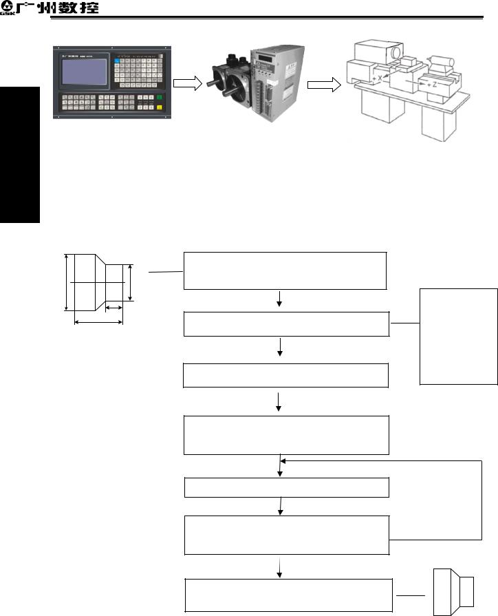
Programming Volume
GSK980TDb Turning CNC System User Manual
Fig. 1-1
Programming is a course of workpiece contours, machining technologies, technology parameters and tool parameters being edit into part programs according to special CNC programming G codes. CNC machining is a course of CNC controlling a machine tool to complete machining of workpiece according requirements of part programs.
Technical flow of CNC machining is as following Fig. 1-2.
Analyse workpiece drawings and confirm machining processing
Edit part programs and record into CNC
Test part programs and execute trial run
Execute toolsetting and set tool offsets and coordinates
Run part programs and machine workpiece
Check part dimension and modify part programs and compensations
O0001
G00 X3.76 Z0
G01 Z-1.28 F50
…
M30
The machining ends and the workpiece is formed
Fig. 1-2
8
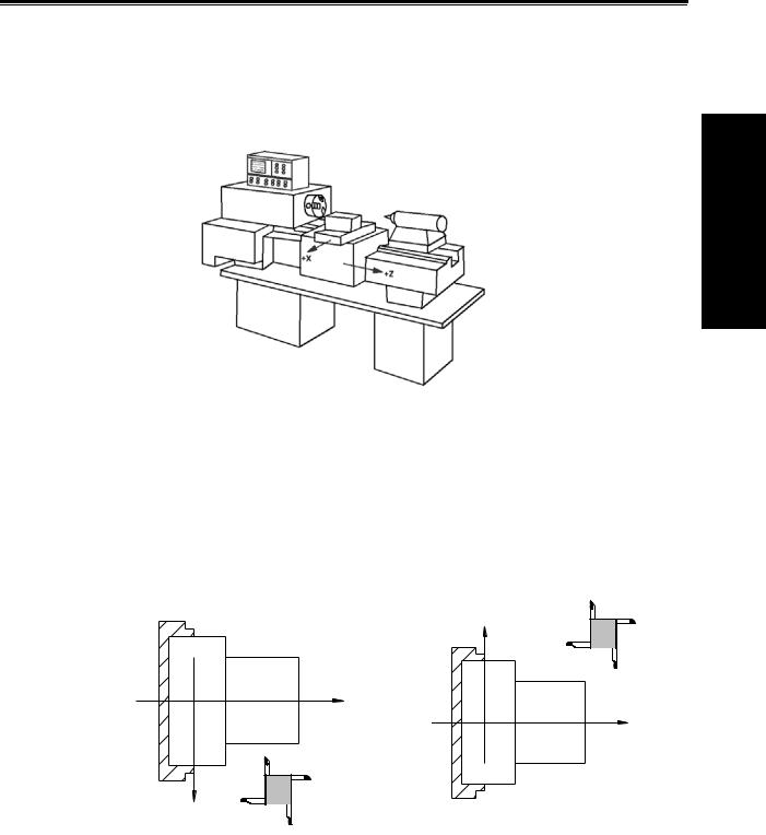
1.3Programming fundamentals
1.3.1Coordinates definition
Sketch map of CNC turning machine is as follows:
Chapter 1 Programming
Programming Volume
Fig. 1-3
GSK980TDb uses a rectangular coordinate system composed of X, Z axis. X axis is perpendicular with axes of spindle and Z axis is parallel with axes of spindle; negative directions of them approach to the workpiece and positive ones are away from it.
There is a front tool post and a rear tool post of NC turning machine according to their relative position between the tool post and the spindle, Fig. 1-5 is a coordinate system of the front tool post and Fig. 1-6 is a rear tool post one. It shows exactly the opposite of X axes, but the same of Z axes from figures. In the manual, it will introduce programming application with the front tool post coordinate system in the following figures and examples.
Z
X
Fig.1-4 Front tool post coordinate system
Fig.1-5 Rear tool post coordinate system
1.3.2 Machine coordinate system, Machine Zero and machine reference point
Machine tool coordinate system is a benchmark one used for CNC counting coordinates and a fixed one on the machine tool. Machine tool zero is a fixed point which position is specified by zero switch or zero return switch on the machine tool. Usually, the zero return switch is installed on max. stroke in X, Z positive direction. Machine reference point is located at the position at which the
9

Programming Volume
GSK980TDb Turning CNC System User Manual
machine zero value adding the data parameter No.114/No.115 value. When No.114/No.115 value is 0, the machine reference point coincides with the machine zero. The coordinates of machine reference point is the No.120/No.121 value. Machine zero return/G28 zero return is to execute the machine reference point return. After the machine zero return/machine reference point return is completed, GSK980TDb machine coordinate system which takes No.120/No.121 value as the reference point.
Note: Do not execute the machine reference point return without the reference point switch installed on the machine tool, otherwise, the motion exceeds the travel limit and the machine to be damaged.
1.3.3Workpiece coordinate system and Program Zero
The workpiece coordinate system is a rectangular coordinate system based on the part drawing, also called floating coordinate system. After the workpiece is installed on the machine, the absolute coordinates of tool’s current position is set by G50 according to the workpiece’s measure, and so the workpiece coordinate system is established in CNC. Generally, Z axis of the workpiece coordinate system coincides with the spindle axis. The established workpiece is valid till it is replaced by a new one.
The current position of workpiece coordinate system set by G50 is the program zero.
Note: Do not execute the machine reference point return without using G50 to set the workpiece coordinate system after power on, otherwise, the alarm occurs.
Workpiece Rod
|
Z1 (Z2) |
|||||||||||||||||||||||||||
|
O2 |
O1 |
||||||||||||||||||||||||||
|
x1/2 (x2/2) |
|||||||||||||||||||||||||||
|
z1 |
|||||||||||||||||||||||||||
|
z2 |
|||||||||||||||||||||||||||
|
(x,z) |
|||||||||||||||||||||||||||
|
(x1,z1) |
|||||||||||||||||||||||||||
|
X/2 |
|||||||||||||||||||||||||||
|
X2 |
X1 |
||||||||||||||||||||||||||
|
(x2,z2) |
Z |
||||||||||||||||||||||||||
|
(0,0) |
|||||||||||||||||||||||||||
|
Z |
|||||||||||||||||||||||||||
|
Fig. 1-6 |
X |
||||||||||||||||||||||||||
In the above figure, XOZ is the coordinate system of machine tool, X1O1Z1 is the workpiece coordinate system of X axis located at the heading of workpiece, X2O2Z2 is the one of X axis located at the ending of workpiece, O point is the machine reference point, A point is the tool nose and coordinates of A point in the above-mentioned coordinate systems is as follows:
A point in the machine tool coordinate system: (x,z); A point in X1O1Z1 coordinate system: (x1,z1);
A point in X2O2Z2 coordinate system: (x2,z2).
10

Chapter 1 Programming
1.3.4Interpolation function
Interpolation is defined as a planar or three dimensional contour formed by path of 2 or multiple axes moving at the same time, also called Contour control. The controlled moving axis is called link axis when the interpolation is executed. The moving distance, direction and speed of it are controlled synchronously in the course of running to form the required Composite motion path. Positioning control is defined that motion end point of one axis or multiple axes instead of the motion path in the course of running is controlled.
GSK980TDb X and Z axis are link axes and 2 axes link CNC system. The system possesses linear, circular and thread interpolation function.
Linear interpolation: Composite motion path of X, Z axis is a straight line from starting point to end point.
Circular interpolation: Composite motion path of X, Z axis is arc radius defined by R or the circle center (I, K) from starting point to end point.
Thread interpolation: Moving distance of X or Z axis or X and Z axis is defined by rotation angle of spindle to form spiral cutting path on the workpiece surface to realize the thread cutting. For thread interpolation, the feed axis rotates along with the spindle, the long axis moves one pitch when the spindle rotates one rev, and the short axis and the long axis directly interpolate.
Example:
|
Fig. 1-7 |
|||
|
… |
|||
|
G32 W-27 F3; |
(B→C; thread interpolation) |
||
|
G1 |
X50 |
Z-30 F100; |
|
|
G1 |
X80 |
Z-50; |
(D→E; linear interpolation) |
|
G3 |
X100 W-10 R10; (E→F; circular interpolation) |
…
M30;
Programming Volume
11
![]()
Programming Volume
GSK980TDb Turning CNC System User Manual
1.3.5Absolute programming and incremental programming
Specify coordinate values of path’s end point or target position in programming and there are 3 kinds of programming method according to coordinate values in programming: absolute programming, incremental programming and compound programming.
Programming with X/Z axis absolute coordinate value to program (present with X, Z) is defined to be the absolute programming;
Programming with X/Z axis incremental movement (present with U, W) is defined to be the incremental programming;
In the system, X, Z axis separately uses the absolute programming and incremental program, which is called the compound programming.
Example: A→B linear interpolation
 Fig.1-8
Absolute programming: G01 X200 Z50; Incremental programming: G01 U100 W-50;
Compound programming: G01 X200 W-50; or G01 U100 Z50
Note: When there are command address X/ U or Z/ W at the same time, X/Z command value is valid.
Example: G50 X10 Z20;
G01 X20 W30 U20 Z30; End point of the block (X20, Z30)
1.3.6Diameter programming and radius programming
Programming methods of X coordinate values are divided into: diameter programming and radius programming.
Diameter programming: when NO.001 Bit2 is 0, X input command value is in diameter and X coordinate is in diameter at the moment;
Radius programming: when NO.001 Bit2 is 1, X input command value is in radius and X coordinate is in radius at the moment.
Table 1-3 Addresses related to diameter or radius programming
|
Address |
Explanation |
Diameter |
Radius |
||
|
programming |
programming |
||||
|
X |
X coordinate |
In diameter |
In radius |
||
|
Addresses |
G50 setting X coordinate |
||||
|
U |
X increment |
In diameter |
In radius |
||
|
related to |
|||||
|
X finishing allowance in G71, G72, G73 |
In diameter |
In radius |
|||
|
diameter or |
|||||
|
Moving distance of tool retraction after |
|||||
|
radius |
In diameter |
In radius |
|||
|
cutting in G75 |
|||||
|
programming |
R |
||||
|
Moving distance of tool retraction when |
In diameter |
In radius |
|||
|
cutting to the end point in G74 |
|||||
12

Chapter 1 Programming
Except for addresses and data in Table 1-1, others (arc radius, taper in G90) are unrelated to diameter or radius programming, and their input values in X direction are defined by the radius.
Note: The diameter programming is used except for the special description in the following explanation.
1.4Structure of an NC program
User needs to compile part programs (called program) according to command formats of CNC system. CNC system executes programs to control the machine tool movement, the spindle starting/stopping, the cooling and the lubricant ON/OFF to complete the machine of workpiece.
Program example:
Programming Volume
|
Fig. 1-9 |
||
|
O0001 |
; |
(Program name) |
|
N0005 |
G0 X100 Z50; |
(Rapidly positioning to A point) |
|
N0010 |
M12; |
(Clamping workpiece) |
|
N0015 |
T0101; |
(Changing No.1 tool and executing its offset) |
|
N0020 |
M3 S600; |
(Starting the spindle with 600 r/min) |
|
N0025 |
M8 |
(Cooling ON) |
|
N0030 |
G1 X50 Z0 F600; |
(Approaching B point with 600mm/min) |
|
N0040 |
W-30 F200; |
(Cutting from B point to C point) |
|
N0050 |
X80 W-20 F150; |
(Cutting from C point to D point) |
|
N0060 |
G0 X100 Z50; |
(Rapidly retracting to A point) |
|
N0070 |
T0100; |
(Canceling the tool offset) |
|
N0080 |
M5 S0; |
(Stopping the spindle) |
|
N0090 |
M9; |
(Cooling OFF) |
|
N0100 |
M13; |
(Releasing workpiece) |
|
N0110 |
M30; |
(End of program, spindle stopping and Cooling OFF) |
|
N0120 |
% |
The tool leaves the path of A→B→C→D→A after the above-mentioned programs are executed.
13

GSK980TDb Turning CNC System User Manual
1.4.1General structure of a program
A program consists of a sequence of blocks, beginning with “OXXXX”(program name)and ending with “%”; a block begins with block number (omitted) and ends with “;” or “*”. See the general structure of program as follows:
Programming Volume
Fig. 1-10 Structure of a program
Program name
There are most 10000 programs stored in GSK980TDb. To identify it, each program has only one program name (there is no the same program name) beginning with command address O and the following 4 digits.
○ □□□□
Program number (0000 9999, the leading zero can be omitted) Address O
Word
A word is the basic command unit to command CNC system to complete the control function, composed of an English letter (called command address) and the following number (operation command with/without sign). The command address describes the meaning of its following operation command and there may be different meaning in the same command address when the different words are combined together. All words of GSK980TDb are in Table 1-4.
Table 1-4 Word table
|
Address |
Command value range |
Function meaning |
Unit |
|
O |
0 9999 |
Program name |
|
|
N |
0 9999 |
Block number |
|
|
G |
00 99 |
Preparatory function |
|
|
X |
-99999999 99999999 |
X coordinate |
Related to IS-B, IS-C |
|
0 99999.999(s) |
Pause time |
||
|
Z |
-99999999 99999999 |
Z coordinate |
Related to IS-B, IS-C |
|
Y |
-99999999 99999999 |
Y coordinate |
Related to IS-B, IS-C |
|
14 |
|
Chapter 1 Programming |
||||||||||||||
|
Address |
Command value range |
Function meaning |
Unit |
|||||||||||
|
-99999999 99999999 |
X increment |
Related to IS-B, IS-C |
||||||||||||
|
0 99999.999(s) |
Pause time |
|||||||||||||
|
U |
||||||||||||||
|
X finishing allowance in G71,G72, |
||||||||||||||
|
-99999 |
99999 |
G73 |
Related to IS-B, IS-C |
Volume |
||||||||||
|
-99999999 99999999 |
X tool retraction clearance in G73 |
Related to IS-B, IS-C |
||||||||||||
|
1 99999 |
Cutting depth in G71 |
Related to IS-B, IS-C |
||||||||||||
|
-99999999 99999999 |
Z increment |
Related to IS-B, IS-C |
||||||||||||
|
Programming |
||||||||||||||
|
1 99999 |
Cutting depth in G72 |
Related to IS-B, IS-C |
||||||||||||
|
W |
||||||||||||||
|
-99999 99999 |
Z finishing allowance in G71,G72, |
Related to IS-B, IS-C |
||||||||||||
|
G73 |
||||||||||||||
|
-99999999 99999999 |
Z tool retraction in G73 |
Related to IS-B, IS-C |
||||||||||||
|
V |
-99999999 99999999 |
Y increment |
Related to IS-B, IS-C |
|||||||||||
|
-99999999 99999999 |
Arc radius |
Related to IS-B, IS-C |
||||||||||||
|
1 99999 |
Tool retraction in G71, G72 |
Related to IS-B, IS-C |
||||||||||||
|
1 9999 (times) |
Roughing cycle times in G73 |
|||||||||||||
|
R |
1 99999 |
Tool retraction clearance in G74, |
Related to IS-B, IS-C |
|||||||||||
|
G75 |
||||||||||||||
|
1 99999 |
Tool retraction clearance from end |
Related to IS-B, IS-C |
||||||||||||
|
point in G74, G75 |
||||||||||||||
|
1 99999999 |
Finishing allowance in G76 |
Related to IS-B, IS-C |
||||||||||||
|
-99999999 99999999 |
Taper in G90, G92, G94, G96 |
Related to IS-B, IS-C |
||||||||||||
|
-99999999 99999999 |
X vector between |
arc |
center |
and |
Related to IS-B, IS-C |
|||||||||
|
I |
starting point |
|||||||||||||
|
0.06 25400 tooth/inch |
Metric thread teeth |
|||||||||||||
|
K |
-99999999 99999999 |
Z vector between |
arc |
center |
and |
Related to IS-B, IS-C |
||||||||
|
starting point |
||||||||||||||
|
0 8000 mm/min |
Feedrate per minute |
|||||||||||||
|
F |
||||||||||||||
|
Feedrate per rev |
||||||||||||||
|
0.0001 500(mm/r) |
||||||||||||||
|
0.001 500 mm |
Metric thread lead |
|||||||||||||
|
S |
0 9999 r/min |
Spindle speed specified |
||||||||||||
|
00 04 |
Multi-gear spindle output |
|||||||||||||
|
T |
01 32 |
Tool function |
||||||||||||
|
00 99 |
Miscellaneous function output, |
|||||||||||||
|
M |
program execution flow |
|||||||||||||
|
9000 9999 |
Subprogram call |
|||||||||||||
|
P |
0 9999999 |
0.001s |
Pause time |
|||||||||||
|
0 9999 |
Calling times of subprogram number |
|||||||||||||
|
0 999 |
Subprogram call times |
|||||||||||||
|
0 9999999 |
X circle movement in G74, G75 |
Related to IS-B, IS-C |
||||||||||||
|
Thread cutting parameter in G76 |
||||||||||||||
15

GSK980TDb Turning CNC System User Manual
|
Address |
Command value range |
Function meaning |
Unit |
||
|
0 9999 |
Initial block number of finishing in |
||||
|
the compound cycle command |
|||||
|
1 9999999 |
Parabola mouth size in G7.2, G7.3 |
Related to IS-B, IS-C |
|||
|
Volume |
0 9999 |
End block number of finishing in the |
Related to IS-B, IS-C |
||
|
1 9999999 |
First cut-in depth in G76 |
||||
|
compound cycle |
|||||
|
0 9999999 |
Z circle movement in G74, G75 |
Related to IS-B, IS-C |
|||
|
Programming |
|||||
|
0 9999 |
Min. cut-in depth in G76 |
Related to IS-B, IS-C |
|||
|
1 9999999 |
|||||
|
Q |
0 360000 |
Offset angle between one-turn |
|||
|
signal and starting point of thread |
|||||
|
cutting at the initial angle in G32 |
|||||
|
Angle between long axis of the |
|||||
|
ellipse and Z in G6.2, G6.3 |
|||||
|
0 9999 |
Angle between long axis of the |
||||
|
ellipse and Z in G7.2, G7.3 |
|||||
|
A |
0 99999999 |
Length of long radius of ellipse in |
Related to IS-B, IS-C |
||
|
G6.2, G6.3 |
|||||
|
B |
0 99999999 |
Length of short radius of ellipse in |
Related to IS-B, IS-C |
||
|
G6.2, G6.3 |
|||||
|
H |
01 99 |
Operand in G65 |
|||
Block
A block which is basic unit of CNC program consists of a sequence of words, ending with “;” or “*” . There is the character “;” or “*” between blocks. “;” is used to separate blocks in the manual as follows:
/ N0030 G0 X20 Z30 ;
End of block Block number Block skip
One block may be with a number of words or only with “; ”ending character(EOB) instead of words. There must be one or more blank space between many words.
There is only one for other addresses except for N, G, S, T, H, L in one block, otherwise the system alarms. The last word in the same address is valid when there are more N, G, S, T, H, L in the same block. The last G code is valid when there are more G codes which are in the same group in one block.
Block number
A block number consists of an address N and its following 4-digit: N0000 N9999, and the leading zero can be omitted. The block number must be at the beginning of block, otherwise the block is invalid.
The block number can be omitted, but there must be the block number when the program calls/skips the target block. The increment of block number is at will and it better to increase or decrease the sequence of block number in order to conveniently search and analyze programs.
16

Chapter 1 Programming
When “Automatic number” in the switch window is set to “ON”, block numbers will be automatically created incrementally and their increment is defined by No.42.
Character for block skip
Insert “/” in the front of block and startup  when some block cannot be executed (cannot be deleted), and the system skips the block and executes the next one. The block with “/” in the front of it is executed if the block skip switch is not started.
Character for end of a program
“%” is an ending character of program. “%” is a mark of communication ended when the program is transmitted. The system will automatically insert “ ” at the end of program.
Program annotation
A program annotation has less than 20 characters (10 Chinese characters) for each program, lies in a bracket following its program name and is expressed only in English and digitals in CNC system; it can be edited in Chinese in PC and displayed in Chinese in CNC system after being downloaded.
1.4.2Main program and subprogram
To simply the programming, when the same or similar machining path and control procedure is used many times, its program commands are edited to a sole program to call. A program which calls the program is the main program and the called program (end with M99) is subprogram. They both take up the program capacity and storage space of system. The subprogram has own name, and can be called at will by the main program and also can run separately. The system returns to the main program to continue when the subprogram ends as follows.
Programming Volume
0001;
G50 X100 Z100;
M3 S1 T0101;
G0 X0 Z0;
G1 U200 Z200 F200;
M98 P21006;
G0 X100 Z100;
M5 S0 T0100; M30;
%
 1006;
1006;
G1 X50 Z50;
U100 W200;
U30 W-15 F250;  M99;
M99;
%
Fig. 1-12 Main program and subprogram
17

Programming Volume
GSK980TDb Turning CNC System User Manual
1.5Program run
1.5.1Sequence of program run
Running the current open program must be in Auto mode. GSK980TDb cannot open two or more programs at the same, and runs only program any time. When the first block is open, the cursor is located in the heading of the first block and can be moved in Edit mode. In the run stop state in Auto
mode, the program starts to run by the cycle start signal ( is pressed or external cycle start signal)from a block pointed by current cursor, usually blocks are executed one by one according to their programming sequence, the program stops running till executing M02 or M30. The cursor moves along with program running and is located at the heading of the current block. Sequence and state of program running are changed in the followings:
zThe program stops running after pressing  or emergent stop button;
zThe program stops running when the system or PLC alarms;
zThe program runs and single block stops (the program run stops after the current block runs completely) in Edit, MDI mode, and then a block pointed by the current cursor starts running
after the system switches into Auto mode,  is pressed or external cycle start signal is switched on;
zThe program stops running in Manual(Jog), Handwheel (MPG), Single Block, Program Reference Point Return, Machine Reference Point Return mode and it continuously runs
from current position after the system is switched into Auto mode and  is pressed or the external cycle start signal is switched on;
|
z The program pauses after pressing |
or the external cycle start signal is switched off, |
|
|
and it continuously runs from current position after pressing |
or the external cycle |
|
|
start signal is switched on; |
z When Single Block is ON, the program pauses after every block is executed completely, and
|
then it continuously runs from the next block after |
is pressed or the external cycle |
|
start signal is switched on; |
zBlock with “/” in the front of it is not executed when the block skipping switch is ON;
zThe system skips to the target block to run after executing G65;
zPlease see Section Three G Commands about execution sequence of G70~73;
zCall corresponding subprograms or macro program to run when executing M98 or M9000~M9999; the system returns to main program to call the next block when executing M99(if M99 specifies a target block number, the system returns to it to run) after the subprograms or macro programs run completely;
zThe system return to the first block to run and the current program is executed repetitively when M99 is executed in a main program.
18

Chapter 1 Programming
1.5.2Execution sequence of word
There are many words (G, X, Z, F, R, M, S, T and so on) and most of M, S, T is transmitted to PLC by NC explaining and others are directly executed by NC. M98, M99, M9000 M9999, S word used to specify the spindle speed r/min, m/min is directly executed by NC.
NC firstly executes G and then M commands when G codes and M00, M01, M02 and M30 are in the same block.
NC firstly executes G and then M commands( without transmitting M signal to PLC) when G codes and M98, M99, M9000 M9999 are in the same block.
When G codes and M, S, T executed by PLC are in the same block, PLC defines M, S, T and G to be executed simultaneously, or execute M, S ,T after G codes. Please see User Manual of machine manufacturer for execution sequence of commands.
Execution sequence of G, M, S, T in the same block defined by GSK980TDb standard PLC program is as follows:
M3, M4, M8, M10, M12, M32, M41, M42, M43, M44, S□□, T□□□□ and G codes are executed simultaneously;
M5, M9, M11, M13, M33 after G codes are executed;
M00, M01, M02, M30 after other commands of current block are executed.
1.6Basic axis incremental system
The incremental system includes least input increment(input) and least command increment(output). Least input increment is the least movement unit of programming movement distance, and least command increment is the least unit of tool traversing on the machine. The two increment systems use mm, inch or deg.
The basic axes include X, Z, and their incremental system has IS-B, IS-C selected by No.00.1
ISC.
|
001 |
ISC |
||||||||
|
ISC |
0 IS-B μ level |
1 IS-C 0.1μ level
In different incremental system, selecting the different axis pulse output mode can receive the different output speed. The selection is executed by No.203 ABPx.
|
203 |
ABP5 |
ABP4 |
ABPZ |
ABPY |
ABPX |
|||||
|
ABPn |
0 axis |
output is |
completed |
by pressing |
‘PULSE+DIRECTION’ |
|||||
|
1 axis output is completed by pressing ‘AB-phase pulse’ |
1.6.1Incremental system speed of basic axis
|
Corresponding |
μ level IS-B |
0.1μ level IS-C |
|||
|
speed |
Metric machine |
Inch machine |
Metric machine |
Inch machine |
|
|
Output mode |
|||||
|
(mm/min) |
(inch/min) |
(mm/min) |
(inch/min) |
||
|
Pulse direction |
60,000 |
6,000 |
6,000 |
600 |
|
|
AB quadrature |
240,000 |
24,000 |
24,000 |
2,400 |
Programming Volume
19

GSK980TDb Turning CNC System User Manual
1.6.2Incremental system unit of basic axis
In different incremental system and different metric/inch, the least input/output increment is different as follows:
|
μ level IS-B |
Least input |
Least command |
||||||||
|
Volume |
||||||||||
|
increment input |
increment output |
|||||||||
|
metric input(G21) |
0.001 |
(mm) |
0.001 |
(mm) |
||||||
|
Metric machine |
0.001 |
(deg) |
0.001 |
(deg) |
||||||
|
inch input(G20) |
0.0001 (inch) |
0.001 |
(mm) |
|||||||
|
Programming |
||||||||||
|
0.001 |
(deg) |
0.001 |
(deg) |
|||||||
|
0.001 |
(deg) |
0.001 |
(deg) |
|||||||
|
metric input (G21) |
0.001 |
(mm) |
0.0001 (inch) |
|||||||
|
Inch machine |
0.001 |
(deg) |
0.001 |
(deg) |
||||||
|
inch input (G20) |
0.0001 (inch) |
0.0001 (inch) |
||||||||
|
0.1μ level IS-C |
Least input |
Least command |
||||||||
|
increment input |
increment output |
|||||||||
|
metric input (G21) |
0.0001 |
(mm) |
0.0001 |
(mm) |
||||||
|
Metric machine |
0.0001 |
(deg) |
0.0001 |
(deg) |
||||||
|
inch input (G20) |
0.00001 (inch) |
0.0001 |
(mm) |
|||||||
|
0.0001 |
(deg) |
0.0001 |
(deg) |
|||||||
|
metric input (G21) |
0.0001 |
(mm) |
0.00001 (inch) |
|||||||
|
Inch machine |
0.0001 |
(deg) |
0.0001 |
(deg) |
||||||
|
inch input (G20) |
0.00001 (inch) |
0.00001 (inch) |
||||||||
|
0.0001 |
(deg) |
0.0001 |
(deg) |
|||||||
Least input increment (input) using the metric or the inch is specified by G20 or G21 or is completed by modifying ISC parameter.
Least command increment(output) using the metric or the inch is determined by the machine, and is set by No.004 SCW.
1.6.3Incremental system data range of basic axis
In different incremental system and pulse output frequency, the corresponding different data range is as follows:
|
Incremental system |
Command data input range |
Data format |
||||
|
metric input (G21) |
-99999.999 |
~ 99999.999 |
(mm) |
5.3 |
||
|
-99999.999 |
~ 99999.999 |
(deg) |
5.3 |
|||
|
μ level IS-B |
||||||
|
inch input (G20) |
-9999.9999 ~ 9999.9999 |
(inch) |
4.4 |
|||
|
-9999.999 |
~ 9999.999 |
(deg) |
4.3 |
|||
|
metric input (G21) |
-9999.9999 |
~ 9999.9999 |
(mm) |
4.4 |
||
|
0.1μ level |
-9999.9999 |
~ 9999.9999 |
(deg) |
4.4 |
||
|
IS-C |
||||||
|
inch input (G20) |
-999.99999 ~ 999.99999 |
(inch) |
3.5 |
|||
|
-999.9999 |
~ 999.9999 |
(deg) |
3.4 |
|||
Note 1: 5.3 in the above table means 5-bit integer and 3-bit decimal. And other data likes these.
Note 2: Refer to the table about the command value range and unit except for the specified in the following descriptions.
20

Chapter 1 Programming
1.6.4Incremental system data range and unit of basic axis
zSpeed parameter
Linear axis speed parameter unit is determined by the machine type. i.e.: metric machine speed unit: mm/min, inch machine is: 0.1inch/min.
Linear axis speed parameter range is determined by the machine type and incremental system type.
Data parameter No. 027: cutting upper speed.
|
Machine type |
Incremental system |
Linear axis speed unit |
Parameter range |
Rotary axis speed unit |
|
|
Metric machine |
μ level IS-B |
mm/min |
10~ 60000 |
||
|
0.1μ level IS-C |
10~ 6000 |
deg/min |
|||
|
Inch machine |
μ level IS-B |
0.1inch/min |
5~60000 |
||
|
0.1μ level IS-C |
5~6000 |
||||
Rotary axis does not execute the metric/inch conversion, the rotary axis speed unit is deg/min; the parameter range is the same that of metric machine.
The different incremental system switch may cause the set max. run speed in the data parameter exceeding max. range permitted by the system, so, the operator should modify the speed parameter to avoid the unexpected when the first power-on after switch.
zIncremental parameter
The unit and range of linear axis incremental parameter are determined by the machine type and incremental system type.
No.045: X software limit.
|
Machine type |
Incremental system |
Linear axis incremental unit |
Linear axis parameter range |
|
|
Metric machine |
μ level IS-B |
0.001mm |
-99, 999.999~ 99,999.999 |
|
|
0.1μ level IS-C |
0.0001 mm |
-9, 999.9999~ 9,999.9999 |
||
|
Inch machine |
μ level IS-B |
0.0001inch |
-9, 999.9999~ 9,999.9999 |
|
|
0.1μ level IS-C |
0.00001 inch |
-999.99999~ 999.99999 |
||
The rotary axis does not execute the metric/inch switch, the unit of rotary axis incremental parameter is determined by the incremental system type. The range of rotary axis incremental parameter is the same that of the metric machine.
|
Machine type |
Incremental system |
Rotary axis speed unit |
Rotary axis parameter range |
||
|
Metric, Inch |
μ level IS-B |
0.001° |
0~ 99999.999 |
||
|
machine |
|||||
|
IS-C |
0.0001° |
0~ 9999.9999 |
|||
|
0.1 μ level |
zProgramming value input range
Linear axis coordinate data unit is determined by the metric/inch input system. i.e. metric input is mm; inch input is inch;
Linear axis coordinate data range is determined by metric/inch input system and incremental system. The range is the same that of the command data input range as follows:
|
Incremental system |
Linear axis coordinate data range |
|||
|
μ level IS-B |
Metric input (G21) |
-99999.999 |
~ 99999.999(mm) |
|
|
Inch input (G20) |
-9999.9999 |
~ 9999.9999(inch) |
||
|
0.1μ level IS-C |
Metric input (G21) |
-9999.9999 |
~ 9999.9999(mm) |
|
|
Inch input (G20) |
-999.99999 |
~ 999.99999(inch) |
||
Programming Volume
21
![]()
Programming Volume
GSK980TDb Turning CNC System User Manual
The rotary axis does not execute the metric/inch switch, the rotary axis coordinate data unit is deg. The range is the same that of metric input.
|
Input type |
Incremental system |
Rotary axis coordinate data range |
|
|
Metric, inch input |
μ level IS-B |
-99999.999 ~ 99999.999 deg |
|
|
0.1μ level IS-C |
-9999.9999 ~ 9999.9999(deg) |
||
zOffset data
Offset data unit is determined by metric/inch input system. i.e. metric input is mm; inch input is inch.
Offset data range is limited to 9999999 and is determined by the metric/inch input system and incremental system. The range is less one level than the command data input range as follows:
|
Input type |
Incremental system |
Offset data unit |
Offset data range |
|
|
Metric input(G21) |
μ level IS-B |
mm |
±9999.999 |
|
|
0.1μ level IS-C |
±999.9999 |
|||
|
Inch input (G20) |
μ level IS-B |
inch |
±999.9999 |
|
|
0.1μ level IS-C |
±99.99999 |
|||
zPitch data compensation
Linear axis pitch compensation unit and range are determined by the machine type and incremental system type. As follows
|
Machine type |
Incremental system |
Linear axis data unit |
Linear axis pitch |
|
|
compensation data range |
||||
|
Metric machine |
μ level IS-B |
0.001mm |
-127 127 |
|
|
0.1μ level IS-C |
0.0001mm |
-127 127 |
||
|
Inch machine |
μ level IS-B |
0.0001inch |
-127 127 |
|
|
0.1μ level IS-C |
0.00001inch |
-127 127 |
||
The rotary axis does not execute the metric/inch switch, the rotary axis pitch compensation unit is
|
determined by the least input unit as follows. |
||||
|
Machine type |
Incremental system |
Rotary axis pitch |
Rotary axis pitch |
|
|
compensation unit |
compensation range |
|||
|
0 255 |
||||
|
Metric, inch machine |
μ level IS-B |
0.001° |
||
|
0.1μ level IS-C |
0.0001° |
0 2550 |
||
1.6.5Program address value unit and range of incremental system of basic axis
zPitch definition and range:
|
Command |
μ level IS-B |
0.1μ level IS-C |
Unit |
||
|
0.0001~500.00 |
|||||
|
Metric input G21 |
F |
0.001~500.000 |
mm/tooth[lead] |
||
|
I |
0.06~25400 |
0.06~2540 |
tooth[lead]/inch |
||
|
0.00001~50.0 |
|||||
|
Inch input G20 |
F |
0.0001~50.00 |
inch/tooth[lead] |
||
|
I |
0.06~2540 |
0.06~254 |
tooth[lead]/inch |
||
22

Chapter 1 Programming
zSpeed F definition
G98 m/min: feed per minute: F unit: mm/min
G99 feed per rev: F definition and range are as follows:
|
Incremental system |
Address |
Metric input |
Inch input |
|
IS-B system |
F G98 |
0 99999.999 (mm/min) |
0 99999.999 (mm/min) |
|
IS-C system |
0 9999.9999 (mm/min) |
0 9999.9999 (mm/min) |
|
|
IS-B system |
F G99 |
0 500 (mm/r) |
0 500 (mm/r) |
|
IS-C system |
0 50 (mm/r) |
0 50 (mm/r) |
|
1.7Additional axis incremental system
Least incremental system in μ level IS-B or 0.1μ level IS-C , the additional axis does not execute the link, and is not used alone. When the least incremental output of additional axis is 0.01 in the low precision requirement and the feedrate must be fast, and so the working efficiency largely increases. The least incremental system of additional axis does not sometime consist with the current least incremental system. The system adds the optional function of the least incremental system of the additional axis (Y, 4th , 5th axis) .
Additional axis incremental system is set by No..187, No..189, No..191 as follows:
|
187 |
YIS1 |
YIS0 |
||||||||||||||||||
|
A4IS1, A4IS0 select the least incremental system of the 4th axis |
||||||||||||||||||||
|
Least input/ output |
||||||||||||||||||||
|
YIS1 |
YIS0 |
Y incremental system |
||||||||||||||||||
|
0 |
0 |
It is the same that the current |
||||||||||||||||||
|
incremental system of basic axis (XZ) |
||||||||||||||||||||
|
0.01 |
||||||||||||||||||||
|
0 |
1 |
IS-A |
||||||||||||||||||
|
0.001 |
||||||||||||||||||||
|
1 |
0 |
IS-B |
||||||||||||||||||
|
0.0001 |
||||||||||||||||||||
|
1 |
1 |
IS-C |
||||||||||||||||||
|
189 |
A4IS1 |
A4IS0 |
||||||||||||||||||
|
A4IS1, A4IS0 select the least incremental system of the 4th axis |
||||||||||||||||||||
|
A4IS1 |
A4IS0 |
4th incremental system |
Least input/ output |
|||||||||||||||||
|
0 |
0 |
It is the same that the current |
||||||||||||||||||
|
incremental system of basic axis (XZ) |
||||||||||||||||||||
|
0 |
1 |
IS-A |
0.01 |
|||||||||||||||||
|
1 |
0 |
IS-B |
0.001 |
|||||||||||||||||
|
1 |
1 |
IS-C |
0.0001 |
|||||||||||||||||
|
191 |
A5IS1 |
A5IS0 |
A5IS1, A5IS0 select the least incremental system of the 5th axis
Programming Volume
23

Programming Volume
GSK980TDb Turning CNC System User Manual
|
A5IS1 |
A5IS0 |
5th incremental system |
Least input/output |
|||||
|
0 |
0 |
It is the same that the current incremental |
||||||
|
system of basic axis (XZ) |
||||||||
|
0 |
1 |
IS-A |
0.01 |
|||||
|
1 |
0 |
IS-B |
0.001 |
|||||
|
1 |
1 |
IS-C |
0.0001 |
|||||
Note: The least I/O in the above table is expressed without considering the metric/inch and rotary axis.
1.7.1Additional axis being the current incremental system
IS-B or IS-C: the relative speed and data range of additional axis is the same that the described in Chapter 1.6.
1.7.2Additional axis being IS-A incremental system
IS-A: the max. speed of additional axis is separate 10 times and 100 times of IS-B and IS-C. The relative data and parameter range are same those of the incremental system of current basic axis (refer to Chapter 1.6).
24

Chapter 2 MSTF Command
CHAPTER 2 MSTF COMMAND
2.1M (miscellaneous function)
M command consists of command address M and its following 1 2 or 4 bit digits, used for controlling the flow of executed program or outputting M commands to PLC.
M □□□□
Command value(00~99, 9000~9999, the leading zero can be omitted) Command address
M98, M99, M9000 M9999 is executed by NC separately and NC does not output M commands to PLC.
M02, M03 are for ending of programs defined by NC, and NC outputs M commands to PLC which can control spindle OFF, cooling OFF and so on.
M98, M99, M9000 M9999 are for calling programs, M02, M30 are for ending of program which are not changed by PLC. Other M commands output to PLC and their function are defined by PLC. Please refer to User Manual from machine manufacturer.
There is only one M command in one block, otherwise the system alarms.
|
Table 2-1 M commands to control program execution |
||
|
Commands |
Functions |
|
|
M02 |
End of program |
|
|
M30 |
End of program |
|
|
M98 |
Call subprograms |
|
|
M99 |
Return from a subprogram; it is executed repeatedly when the program |
|
|
ends in M99(the current program is not called by other programs) |
||
|
M9000 M9999 |
Call macro programs(their program numbers are more than 9000) |
|
2.1.1 End of program M02
Command format: M02 or M2
Command function: In Auto mode, after other commands of current block are executed, the automatic run stops, and the cursor stops a block in M02 and does not return to the start of program. The cursor must return to the start of program when the program is executed again.
Besides the above-mentioned function executed by NC, M02 function is also defined by PLC ladder diagram as follows: current output of CNC is reserved after M02 is executed.
2.1.2 End of program run M30
Command format: M30
Command function: In Auto mode, after other commands of current block are executed in M30, the automatic run stops, the amount of workpiece is added 1, the tool nose radius compensation is cancelled and the cursor returns to the start of program (whether the cursor return to the start of program or not is defined by parameters).
If No.005 Bit 4 is set to 0, the cursor does not return to the beginning of program, and the cursor returns immediately after the program is executed completely when No.005 Bit 4 is set to 1.
Programming Volume
25

Programming Volume
GSK980TDb Turning CNC System User Manual
Except for the above-mentioned function executed by NC, M30 function is also defined by PLC ladder diagram as follows: the system closes M03, M04 or M08 signal output and outputs M05 signal after M30 is executed.
2.1.3Subprogram call M98
Command format: M98 P○○○○□□□□
Called subprogram number 0000 9999 . The leading zero of subprogram number can be omitted when the calling times is not input; the subprogram number must be with 4 digits when the calling times is input.. Call times: 1 9999. The calling times cannot be input when it is 1.
Command function: In Auto mode, after other commands are executed in M98, CNC calls subprograms specified by P, and subprograms are executed 9999 times at most. M98 is invalid in MDI mode.
2.1.4 Return from subprogram M99
Command format: M99 P○○○○
 Executed block after returning to the main program is 0000 9999 and its leading zero can be omitted.
Command function: After other commands of current block in the subprogram are executed, the system returns to the main program and continues to execute next block specified by P, and calls a block following M98 of current subprogram when P is not input. The current program is executed repeatedly when M99 is defined to end of program (namely, the current program is executed without calling other programs). M99 is invalid in MDI mode.
Example: Execution path of calling subprogram (with P in M99) as Fig. 2-1. Execution path of calling subprogram (without P in M99) as Fig. 2-2.
Fig. 2-1 Execution path of calling subprogram (with P in M99)
26

Chapter 2 MSTF Command
Fig. 2-2 Execution path of calling subprogram (without P in M99)
Subprogram calls can be nested up to four levels as shown in Fig. 2-3.
|
M a in p ro g ram |
S ub p ro g ram |
S u b p ro gr am |
S u bp ro g ram |
|||
|
O1 001 |
O 10 02 |
O1 003 |
O 10 04 |
|||
|
… |
. .. |
… |
. .. |
|||
|
… |
. .. |
… |
. .. |
|||
|
… |
. .. |
… |
. .. |
|||
|
M98 P10 02; |
M 98P 100 3; |
M98 P10 04; |
M 98P 100 5; |
|||
|
… |
. .. |
… |
. .. |
|||
|
… |
. .. |
… |
. .. |
|||
|
… |
. .. |
… |
. .. |
|||
|
… |
. .. |
… |
. .. |
|||
|
M30 ; |
M 99; |
M99 ; |
M 99; |
|||
|
L ev el 1 |
L ev el 2 |
L ev el 3 |
Fig. 2-3 Subprogram nesting
S u b pr og ra m
O10 05
…
…
…
…
…
…
…
…
M99 ;
Le vel 4
2.1.5Macro program call M9000 M9999
Command format: M□□□□
9000 9999
Command function: call macro programs corresponding to command values (O9000 O9999). Macro programs: O9000 O9999 programs are for machine manufacturer, used for editing
subprogram with special functions, called macro programs. The system must have 2-level operation level (machine manufacturer) when editing O9000 O9999, and macro programs calling commands are executed to call with 3 5 operation level. M9000 M9999 are invalid in MDI mode.
2.1.6M commands defined by standard PLC ladder diagram
Other M commands are defined by PLC except for the above-mentioned ones(M02, M30, M98, M99, M9000 M9999). The following M commands are defined by standard PLC, and GSK980TDb Turning Machine CNC system is used for controlling machine tool. Refer to commands of machine manufacturer about functions, significations, control time sequence and logic of M commands.
M commands defined by standard PLC ladder diagram.
Programming Volume
27

GSK980TDb Turning CNC System User Manual
|
Table 2-2 M commands |
|||||
|
Remark |
|||||
|
Command |
Function |
||||
|
M00 |
Program pause |
||||
|
M01 |
Program optional stop |
||||
|
Volume |
|||||
|
*M05 |
Spindle stop |
||||
|
M03 |
Spindle clockwise (CW) |
Functions interlocked |
|||
|
M04 |
Spindle counterclockwise (CCW) |
and states reserved |
|||
|
M08 |
Cooling ON |
Functions interlocked |
|||
|
Programming |
and states reserved |
||||
|
M13 |
Chuck releasing |
||||
|
*M09 |
Cooling OFF |
and states reserved |
|||
|
M10 |
Tailstock forward |
Functions interlocked |
|||
|
M11 |
Tailstock backward |
and states reserved |
|||
|
M12 |
Chuck clamping |
Functions interlocked |
|||
|
M14 |
Spindle position control |
Functions interlocked |
|||
|
and states reserved |
|||||
|
*M15 |
Spindle speed control |
||||
|
M20 |
Spindle clamping |
Functions interlocked |
|||
|
and states reserved |
|||||
|
*M21 |
Spindle releasing |
||||
|
M24 |
The 2nd spindle position control |
Functions interlocked |
|||
|
and states reserved |
|||||
|
*M25 |
The 2nd spindle speed control |
||||
|
M32 |
Lubricating ON |
Functions interlocked |
|||
|
*M33 |
Lubricating OFF |
and states reserved |
|||
|
*M50 |
Spindle orientation cancel |
||||
|
M51 |
Spindle orientate to No. 1 point |
||||
|
M52 |
Spindle orientate to No. 2 point |
||||
|
M53 |
Spindle orientate to No. 3 point |
Functions interlocked |
|||
|
M54 |
Spindle orientate to No. 4 point |
||||
|
and states reserved |
|||||
|
M55 |
Spindle orientate to No. 5 point |
||||
|
M56 |
Spindle orientate to No. 6 point |
||||
|
M57 |
Spindle orientate to No. 7 point |
||||
|
M58 |
Spindle orientate to No. 8 point |
||||
|
M63 |
The 2nd spindle rotation CCW |
Functions interlocked |
|||
|
M64 |
The 2nd spindle rotation CW |
||||
|
and states reserved |
|||||
|
*M65 |
The 2nd spindle stop |
||||
|
*M41, M42, |
Spindle automatic gear shifting |
Functions interlocked |
|||
|
M43, M44 |
and states reserved |
||||
Note: Commands with “*” defined by standard PLC is valid when power on.
2.1.7Program stop M00
Command format: M00 or M0
Command function: After M00 is executed, the program stops and the system displays “Pause”, and then the program continuously runs after the cycle start key is pressed.
2.1.8Program optional stop M01
Command format: M01 or M1
28

Chapter 2 MSTF Command
Command function: in AUTO, MDI mode, it is valid. Press  and its indicator lights and the system enters the optional stop state, at the moment, the program stops run and the system displays “PAUSE” after M01 is executed, after the cycle start key is pressed, the program continuously runs. When the program optional stop switch is not open, the program does not pause even if M01 runs.
2.1.9Spindle CW, CCW and stop control M03, M04, M05
Command format: M03 or M3 M04 or M4; M05 or M5.
Command function: M03: Spindle CW rotation; M04: Spindle CCW rotation; M05: Spindle stop.
Note: Refer to time sequence of output defined by standard PLC ladder in VOLUME INSTALLATION
& CONNECTION.
2.1.10 Cooling control M08, M09
Command format: M08 or M8; M09 or M9;
Command function: M08: Cooling ON; M09: Cooling OFF.
Note: Refer to time sequence and logic of M08, M09 defined by standard PLC ladder in VOLUME
INSTALLATION & CONNECTION.
2.1.11 Tailstock control M10, M11
Command format: M10; M11;
Command function: M10: tailstock going forward; M11: tailstock going backward.
Note: Refer to time sequence and logic of M10, M11 defined by standard PLC ladder in VOLUME
INSTALLATION & CONNECTION
2.1.12 Chuck control M12, M13
Command format: M12; M13;
Command function: M12: chuck clamping; M13: chuck releasing.
Note: Refer to time sequence and logic of M12, M13 defined by standard PLC ladder in VOLUME
INSTALLATION & CONNECTION.
2.1.13Spindle position/speed control switch M14, M15
Command format M14 M15
Command function M14 spindle is in the position control mode from speed control mode;
Programming Volume
29

Programming Volume
GSK980TDb Turning CNC System User Manual
M15 spindle is in speed control mode from the position control mode.
Note: Refer to time sequence and logic of M14, M15 defined by standard PLC ladder in VOLUME
INSTALLATION & CONNECTION.
2.1.14Spindle clamped/released M20, M21
Command format M20 M21
Command function M20 spindle clamped M21 spindle released
Note: Refer to time sequence and logic of M20, M21 defined by standard PLC ladder in VOLUME
INSTALLATION & CONNECTION.
2.1.15 The 2nd spindle position/speed switch M24, M25
Command format M24 M25
Command function M24 The 2nd spindle is switched from the speed control mode to the position control mode;
M25 The 2nd spindle is switched from the position control mode to the speed control mode.
Note: Refer to time sequence and logic of M24, M25 defined by standard PLC ladder in VOLUME
INSTALLATION&CONNECTION.
2.1.16Lubricating control M32, M33
Command format M32 M33
Command function M32 lubricating ON; M33 lubricating OFF.
Note: Refer to time sequence and logic of M32, M33 defined by standard PLC ladder in VOLUME
INSTALLATION&CONNECTION.
2.1.17Spindle automatic gear change M41, M42, M43, M44
Command format M4n (n=1, 2, 3, 4)
Command function When the system executes M4n, the spindle changes to gear n.
Note: Refer to time sequence and logic of M41, M42, M43, M44 defined by standard PLC ladder in VOLUME INSTALLATION&CONNECTION.
2.1.18Spindle 8-point orientation M50 M58
Command format M5n (n=0 
Command function M50 cancel orientation state; M5n(n=0 the spindle oriented to No. n point.
Note: Refer to time sequence and logic of M50 M58 defined by standard PLC ladder in VOLUME
INSTALLATION & CONNECTION.
30

Chapter 2 MSTF Command
2.1.19The 2nd spindle rotation CCW, rotation CW , stop M63, M64, M65
Command format: M63 M64 M65
Command function:
M63: spindle rotation CCW; M64: spindle rotation CW; M65: spindle stop.
Note 1: The sequence of M63, M64, M65 defined by the standard PLC is the same that of M03, M04, M05. Note 2: The function is enabled when the 2nd spindle function is valid.
2.2Spindle function
S command is used for controlling spindle speed and this GSK980TDb has two modes to control
it:
Spindle speed switching value control: S□□(2 digits command value)is executed by PLC, and PLC outputs switching value signal to machine tool to change spindle speed with grades.
Spindle speed analog voltage control: S□□□□(4 digits command value)specifies actual speed of spindle and NC outputs 0~10V analog voltage signal to spindle servo or converter to realize stepless spindle speed.
2.2.1Spindle speed switching value control
Spindle speed is controlled by switching value when No.001 BIT4 is set to 0. There is only one S command in a block, otherwise the system alarms.
Their executing sequence is defined by PLC when S command and word for moving function are in the same block. Please refer to User Manual from machine manufacturer.
When spindle speed is controlled by switching value, GSK980TDb Turning CNC system is used for machine tool and the time sequence and logic of executing S command is according to User Manual from machine manufacturer. Refer to S command defined by standard PLC of GSK980TDb as follows:
Command format: S□□
00 04(the leading zero can be omitted): No.1 No.4 gear of spindle speed is controlled by switching value.
In spindle speed switching value control mode, after S signal transmits to PLC, the system dwells time defined by No.081, then return FIN signal, and the dwell time is called runtime of S command.
Dwell time
|
Start to execute S command |
Start to execute the following word or block |
S01, S02, S03, S04 output are reserved when resetting CNC.
S1 S4 output are invalid when CNC is switched on. The corresponding S signal output is valid and reserved, and others are cancelled at the same time when executing one of S01, S02, S03, S04. When executing S00, S1 S4 output are cancelled and only one of S1 S4 is valid at the same time.
Programming Volume
31
 Loading…