
PSP SERIES
USER MANUAL
i
CONTENTS PAGE
1. Product Introduction……………………………………………………
1
2.
Safety Information……………………….……………….…… 3
3. Technical Specification………….…………………………….. 7
4.
Panel Controls and Indicator………………………….…..…. 9
5. Functional Description of Operation Element……………….. 12
6. Operating Instruction with Keypad Input…………………………. 13
7. Disposal………………………………………………………….. 17
8. Rectification of Faults………….……………………………… 18
9. Maintenance……….……….……………………………………. 19
10. APPENDIX: Connecting the Programmable Power Supply
via RS232 Interface…………………………………………………………… 21
PSP SERIES
USER MANUAL
ii
Declaration of Conformity
We
GOOD WILL INSTRUMENT CO., LTD.
No. 7-1, Jhongsing Rd., Tucheng City, Taipei County 236, Taiwan.
declares that the below mentioned product
PSP-603, PSP-405, PSP-2010
Are herewith confirmed to comply with the requirements set out in the Council
Directive on the Approximation of the Law of Member States relating to
Electromagnetic Compatibility (89/336/EEC, 92/31/EEC, 93/68/EEC) and Low
Voltage Equipment Directive (73/23/EEC, 93/68/EEC). For the evaluation regarding
the Electromagnetic Compatibility and Low Voltage Equipment Directive, the
following standards were applied:
◎ EMC
EN 61326-1:
Electrical equipment for measurement, control and laboratory use ––
EMC requirements (1997+A1: 1998)
Conducted and Radiated Emissions
EN 55011: 1998
Electrostatic Discharge
EN 61000-4-2: 1995+A1:1998
Current Harmonic
EN 61000-3-2: 1995+A1: 1998+A2: 1998
Radiated Immunity
EN 61000-4-3: 1996
Voltage Fluctuation
EN 61000-3-3: 1995
Electrical Fast Transients
EN 61000-4-4: 1995
————————-
Surge Immunity
EN 61000-4-5: 1995
————————-
Conducted Susceptibility
EN 61000-4-6: 1996
————————-
P.F.Magnetic Field
EN 61000-4-8: 1993
————————-
Voltage Dips/ Interrupts
EN 61000-4-11: 1994
◎ Safety
Low Voltage Equipment Directive 73/23/EEC & amended by 93/68/EEC
IEC/EN 61010-1: 2001
EN 60950 :1992+A1:1993+A2 :1993+A3 :1995+A4 : 1997+A11: 1997
IEC 60950:1991+A1:1992+A2 :1993+A3 :1995+A4 : 1996
![]()
PSP SERIES
USER MANUAL
1.Product Introduction…………………………………………………… 1
2.Safety Information……………………….……………….…… 3
3.Technical Specification………….…………………………….. 7
4.Panel Controls and Indicator………………………….…..…. 9
5.Functional Description of Operation Element……………….. 12
|
6. Operating Instruction with Keypad Input…………………………. |
13 |
7.Disposal………………………………………………………….. 17
8.Rectification of Faults………….……………………………… 18
9.Maintenance……….……….……………………………………. 19
10.APPENDIX: Connecting the Programmable Power Supply
|
via RS232 Interface…………………………………………………………… |
21 |
PSP SERIES
USER MANUAL
Declaration of Conformity
We
GOOD WILL INSTRUMENT CO., LTD.
No. 7-1, Jhongsing Rd., Tucheng City, Taipei County 236, Taiwan. declares that the below mentioned product
PSP-603, PSP-405, PSP-2010
Are herewith confirmed to comply with the requirements set out in the Council Directive on the Approximation of the Law of Member States relating to Electromagnetic Compatibility (89/336/EEC, 92/31/EEC, 93/68/EEC) and Low Voltage Equipment Directive (73/23/EEC, 93/68/EEC). For the evaluation regarding the Electromagnetic Compatibility and Low Voltage Equipment Directive, the following standards were applied:
EMC
EN 61326-1: Electrical equipment for measurement, control and laboratory use –– EMC requirements (1997+A1: 1998)
|
Conducted and Radiated Emissions |
Electrostatic Discharge |
|
|
EN 55011: 1998 |
EN 61000-4-2: 1995+A1:1998 |
|
|
Current Harmonic |
Radiated Immunity |
|
|
EN 61000-3-2: 1995+A1: 1998+A2: 1998 |
EN 61000-4-3: 1996 |
|
|
Voltage Fluctuation |
Electrical Fast Transients |
|
|
EN 61000-3-3: 1995 |
EN 61000-4-4: 1995 |
|
|
————————- |
Surge Immunity |
|
|
EN 61000-4-5: 1995 |
||
|
————————- |
Conducted Susceptibility |
|
|
EN 61000-4-6: 1996 |
||
|
————————- |
P.F.Magnetic Field |
|
|
EN 61000-4-8: 1993 |
||
|
————————- |
Voltage Dips/ Interrupts |
|
|
EN 61000-4-11: 1994 |
||
Safety
Low Voltage Equipment Directive 73/23/EEC & amended by 93/68/EEC
IEC/EN 61010-1: 2001
EN 60950 :1992+A1:1993+A2 :1993+A3 :1995+A4 : 1997+A11: 1997 IEC 60950:1991+A1:1992+A2 :1993+A3 :1995+A4 : 1996

PSP SERIES
USER MANUAL
SAFETY TERMS AND SYMBOLS
These terms may appear in this manual or on the product:
WARNING. Warning statements identify condition or practices that could result in injury or loss of life.
CAUTION. Caution statements identify conditions or practices that could result in damage to this product or other property.
The following symbols may appear in this manual or on the product:
|
DANGER |
ATTENTION |
Protective |
Earth (ground) |
Frame or |
|
High Voltage |
refer to Manual |
Conductor |
Terminal |
Chassis |
|
Terminal |
Terminal |
PSP SERIES
USER MANUAL
FOR UNITED KINGDOM ONLY
NOTE: This lead/appliance must only be wired by competent persons
WARNING: THIS APPLIANCE MUST BE EARTHED
IMPORTANT: The wires in this lead are coloured in accordance with the following code:
|
Green/ Yellow: |
Earth |
|
Blue: |
Neutral |
|
Brown: |
Live (Phase) |
As the colours of the wires in main leads may not correspond with the colours marking identified in your plug/appliance, proceed as follows:
The wire which is coloured Green & Yellow must be connected to the Earth terminal marked with the letter E or by the earth symbol  or coloured Green or Green & Yellow.
The wire which is coloured Blue must be connected to the terminal which is marked with the letter N or coloured Blue or Black.

PSP SERIES
USER MANUAL
The wire which is coloured Brown must be connected to the
terminal marked with the letter L or P or coloured Brown or Red.
If in doubt, consult the instructions provided with the equipment or contact the supplier.
This cable/appliance should be protected by a suitably rated and approved HBC mains fuse: refer to the rating information on the equipment and/or user instructions for details. As a guide, cable of 0.75mm2 should be protected by a 3A or 5A fuse. Larger conductors would normally require 13A types, depending on the connection method used.
Any moulded mains connector that requires removal /replacement must be destroyed by removal of any fuse & fuse carrier and disposed of immediately, as a plug with bared wires is hazardous if a engaged in live socket. Any re-wiring must be carried out in accordance with the information detailed on this label.
PSP SERIES
USER MANUAL
1. Product Introduction
The PSP series is a programmable switching power supply with backlit liquid crystal display built to the latest technological standards. Construction is in accordance with VDE 0411 = EN 61010. Moreover, the PSP series has been EMV-tested and fulfils the requirements of the applicable European and national directives. Conformance to these has been proven; the relevant statements and documents are lodged with the manufacturer.
Note: This is a Class A device which can cause RF interference within the home.
To maintain this condition and to guarantee safe operation, the user must observe these operating instructions without fail.
Application Note
zConnection of low-voltage loads to the marked connection sockets provided for this purpose and their operation at a voltage between 0 to rating voltage.
zThe current consumption of a connected load may not exceed rating current.
zThe Switching Power Supply PSP series is suitable for connection to 115 or 230 V 50/60 Hz AC power sockets.
zOperation must not take place under unfavorable ambient conditions including:
-Moisture or excessive air humidity.
-Dust and combustible gases, fumes or solvents.

PSP SERIES
USER MANUAL
2. Safety Information
Note: Damage caused by failure to observe the operating instructions voids the guarantee.
We accept no liability for consequential damage and accept no responsibility for damage to property or injury to persons caused by improper operation or failure to observe the safety instructions. Such cases void the guarantee. a) Installation and handling safety instructions
Observe the following rules when installing the instrument:
a1. Avoid use the instrument in extremely cold or hot locations or directly adjacent to a heating fan.
a2. Never switch the instrument on immediately when it is brought from a cold environment into a warm room until the instrument comes to room temperature as under the adverse conditions, the resultant condensation may destroy the instrument.
a3. Ensure there is proper ventilation for the vents in the case (front left side and cooling fan on the rear) to prevent heat build-up from damaging the instrument.
a4. Never operate the instrument near hot soldering irons.
a5. Do not place the Power Supply with its front panel down to avoid damaging the operating controls.
b) General safety requirements
The Switching Power Supply PSP series has been fully inspected and tested with technically safe condition before shipping from the factory. To maintain this condition and to ensure safe operation, it is essential for the user to observe the safety instructions and warning notes which
3
PSP SERIES
USER MANUAL
-Thunderstorms or storm conditions such as strong electrostatic fields,
etc.
Any use other than above description may leads to damage to the unit; or causes dangers such as short circuit, fire, electric shock, etc. No part of the product may be modified or converted. The safety instructions are to be followed without fail.
2

PSP SERIES
USER MANUAL
are contained in this user manual.
The instrument is constructed to Protection Class I. It is equipped with a VDE-approved power supply with safety cable and may only be used with and connected to AC supplies with safety earthing.
Ensure that the (yellow/green) earthed wire in the instrument, in its power cable and in the AC supply remains sound, because a damaged earth wire can endanger life.
In commercial facilities the accident-prevention regulations of the industrial employers’ liability association for electrical systems and equipment must be observed.
In schools, training facilities, hobby and self-help workshops, the operation of power supplies and accessories must be supervised by the trained personnel.
Make sure that only the fuses of the given types and nominal current ratings are used as replacements. The use of repaired fuses or the bridging of fuse holders is not permitted. A small flat-bladed screwdriver is required to change the AC fuse. Carefully lever up the cover in the AC power socket and withdraw it. Remove the defective fuse and replace it with an intact one of the same type and nominal current rating. Afterwards replace the fuse cover.
The measuring instrument is operated only when the case is securely closed and screwed up.
PSP SERIES
USER MANUAL
While proceeding the operation of power supplies, the wearing of metal or other conducting jewelry such as chains, bracelets, rings, etc. is not recommended.
Note: Power supplies are not intended for use with/on people or animals.
When connecting the outputs of more than one power supply in series voltages may danger to life (> 35 VDC). Only power supplies with an identical output (current and voltage) specification may be placed in series or in parallel, otherwise the weaker of the two will be damaged. The instrument is to be placed onto a hard, non-inflammable base, so that cooling air can enter unhindered. The cooling of the unit occurs predominantly through convection.
Note: Power supply ventilation holes should not be covered.
Power supplies and their connected loads should not be left operating unsupervised. There are measures for the protection and safety of connected loads in the face of power supply incidents (e.g. overvoltages, complete failure) and effects and dangers stemming from the loads themselves (e.g. unduly-high current consumption).
Faulty power supplies can produce voltages over 50 V DC, which can be dangerous even when the indicated normal output voltages of the units are lower than this.
Note: For power-on work, only tools expressly intended for this should be used.

PSP SERIES
USER MANUAL
The power supply outputs and connecting leads, sockets and terminals must be protected from being touched directly. In addition, the leads used must be sufficiently insulated and voltage-proof and the contact
points safe from being touched (safety sockets).
Use of bare metal leads and contacts should be avoided. All such items are to be covered by suitable, nonflammable insulating material or other measures taken and therefore protected from being touched directly. The electrically conducting parts of the connected load must also be appropriately protected from being touched directly.
If the instrument is assumed that safe operation is no longer possible according to the following phenomena, then the unit must be switched off and protected against unintentional operation:
—the unit shows visible signs of damage,
—the unit no longer functions and
—after prolonged storage under unfavourable conditions or
—after severe transportation stress.
Do switch on the switched power supply immediately when it has been brought from a cold environment into a warm room until it comes to room temperature as under adverse conditions, the resultant condensation can destroy the unit.
PSP SERIES
USER MANUAL
3. Technical Specifications
|
Model |
PSP-603 |
PSP-405 |
PSP-2010 |
||||
|
Operating voltage |
115/230 VAC ±15% |
||||||
|
Power frequency |
50/60 Hz |
||||||
|
Power consumption |
approx. 420VA max. |
||||||
|
Power output |
200W max. |
||||||
|
Output voltage |
0~60VDC, 20mV |
0~40VDC, |
0~20VDC, 10mV |
||||
|
resolution |
10mV resolution |
resolution |
|||||
|
Program Accuracy |
±0.05%±4 digits |
±0.05%±3 digits |
±0.05%±3 digits |
||||
|
Output Current |
0~3.5A |
0~5A |
0~10A |
||||
|
2mA resolution |
2mA resolution |
5mA resolution |
|||||
|
Program Accuracy |
±0.1%±5 digits |
±0.1%±5 digits |
±0.3%±10 digits |
||||
|
Voltage Load Regulation |
10 mV |
||||||
|
Current Load Regulation |
5 mA |
||||||
|
Voltage Line Regulation. |
0.05% |
||||||
|
Current Line Regulation |
0.05% |
||||||
|
Ripple Voltage |
20 mV rms |
||||||
|
Ripple Current |
10 mArms |
||||||
|
Readback Resolution |
20mV 2mA |
10mV 2mA |
10mV 5mA |
||||
|
(Meter) |
|||||||
|
Response |
Rise Time |
150ms ( 95% rating load) |
|||||
|
Time |
Fall Time |
150ms ( 10% rating load) |
|||||
|
Recovery Time |
30ms (50% Load Change, Minimum load 0.5A) |
||||||
|
Readback Accuracy (Meter) |
|||||||
|
Voltage |
±0.05%±4 digits |
±0.05%±3 digits |
±0.05%±3 digits |
||||
|
Current |
±0.1%±5 digits |
±0.1%±5 digits |
±0.3%±10 digits |
||||
|
Digital Display |
Multi-line LCD with background lighting |
||||||
|
AC fuse |
Slow-blow T6.3A/250V for 115V, T3.15A/250V for 230V |
||||||
|
Command Process Time |
250ms |
||||||
|
Interface (Standard) |
RS-232C |
||||||
|
Weight |
Approx. 4 kgs |
||||||
|
Dimensions |
Approx. 225×100×305 m/m |
||||||
|
(W × H × L) |
(without stand and power cable) |

PSP SERIES
USER MANUAL
Environmental Conditions
|
Operating |
Indoor use, altitude up to 2000m. |
|
|
Environment |
Ambient Temperature 0 to 40 . |
|
|
Relative Humidity 80%(Maximum). |
||
|
Installation category |
II |
|
|
Pollution Degree |
2 |
|
|
Operating temperature & |
0°C to +40°C |
|
|
Humidity |
80% (Maximum), non-condensing |
|
|
Storage temperature range |
-10°C to +70°C |
|
|
Accessories |
Power cord…………….……….. 1 |
|
|
Instruction manual…………… 1 |
||
|
Test Lead……….……………. 1 |
PSP SERIES
USER MANUAL
4. Panel Controls & Indicator
Front Panel
1) 4 mm safety sockets: 1a negative connection «-«, 1b positive connection «+» and 1c earth connection.
2)«POWER» AC switch for switching the power supply on («1») and off («0»).
3)Encoder wheel for changing the V SET, V LIMIT, I LIMIT, P LIMIT, +%, and -% parameter settings.
4)Keypad for actual operation of the Switching Power Supply PSP series. The exact description follows below.
5)Backlit LCD Display with indication of the output voltage, current, power settings and indication of the V, I and P limits. Additionally, indication of OUTPUT On or Off and keypad locked or unlocked.
Rear Panel
6)AC rear power socket.
7)RS-232 interface (with optocoupler) for connection to PC.
 Cooling fan.

|
PSP SERIES |
PSP SERIES |
|
USER MANUAL |
USER MANUAL |
|
z |
Front Panel |
z |
Rear Panel |
Figure 4-1
Figure 4-2
 Loading…
Сообщаем, что продажа осуществляется только клиентам, ведущим хозяйственную деятельность.
Важная информация для клиентов из России и Беларуси. Остановка продажи.
Здесь вы узнаете больше
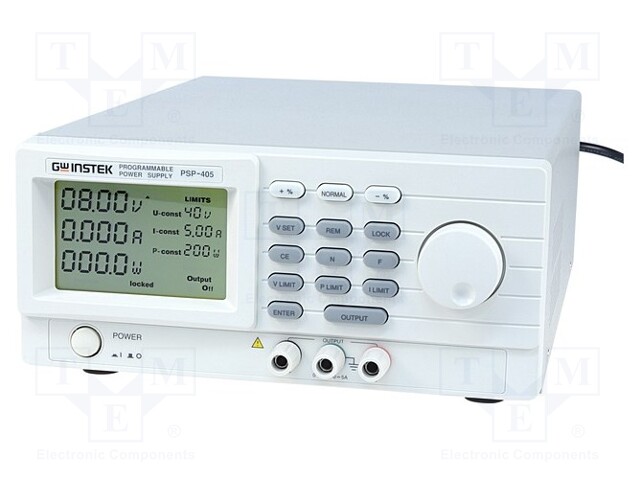
Обозначение производителя: PSP-405
Код TME: PSP-405
|
Производитель |
GW INSTEK | |
|
Тип блока питания |
лабораторный программируемый | |
|
Вид блока питания |
импульсный, одноканальный, программируемый | |
|
Вид используемого дисплея |
LCD | |
|
Кол-во каналов |
1 | |
|
Выходное напряжение |
0…40В DC | |
|
Выходной ток |
0…5А | |
|
Шумы и пульсация, регулир. напряжение |
≤20мVrms | |
|
Интерфейс |
RS232 | |
|
Защита |
от перегрева OTP, от перегрузок OPP, от перенапряжения OVP | |
|
Конструкция вилки |
EU | |
|
Размеры |
225x100x305мм | |
|
Подсветка |
есть |
Характеристики измерительных приборов
- интеллектуальное управление охлаждением
- работа в режиме стабилизации тока или напряжения
Стандартная комплектация
- измерительный провод
- кабель питания
Напряжение питания
- 100…240В AC
Масса брутто4391.1 g
Количество штук (Кратность заказа: 1)
Спросить о цене при большом количестве
Способ и стоимость доставки
Платежи

Документация не актуализируется автоматически, однако, мы прилагаем максимум усилий, чтобы предоставлять новейшие версии документов.