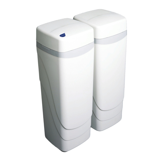
Умягчитель Аквафор WaterMax 152APQ предназначен для умягчения и очистки поступающей воды от содержащегося в ней сероводорода.
Умягчитель обладает двумя баками для сорбентов. Емкость одного из них — 30 литров, второго — 15. Большой бак заполнен умягчающей смолой, которая удаляет из воды соли жесткости и сероводород. Меньший бак вы можете заполнить солью исходя из ваших потребностей. Таким образом, умягчитель сможет устранять хлор, органические и прочие примеси. Благодаря технологии Bakteristat бактерии внутри фильтра не размножаются.
Для умягчения воды используются гранулы ионообменной смолы Fine. Их размер намного меньше, чем в стандартных умягчающих фильтров, и, как следствие, поверхность контакта больше. Этот факт положительно влияет на скорость ионного обмена. Кроме того, смола зажата между двумя сетками с размерами ячеек 20 мкм.
Преимущества фильтра:
- расход соли и времени на регенерацию намного меньше
- объем фильтра используется на 100%, т.к. не образуется застойных мест
- сетка защищает ионообменную смолу от взвесей и механических примесей
Алгоритм регенерации Аквафор WaterMax 152APQ
Контроллер собирает информацию о фактическом потреблении воды по дням недели. Затем он сравнивает данные с текущим потреблением воды. С учетом оставшегося ресурса смолы контроллер принимает решение о необходимости регенерации.
Купить умягчитель Аквафор WaterMax 152APQ
![]()
Наш интернет-магазин — это официальный дилер оборудования АКВАФОР. В каталоге представлены все фильтры для очистки воды, которые вы можете купить по низкой цене и с быстрой, бесплатной доставкой по Москве и МО.
Все фильтры АКВАФОР для организаций
- Manuals
- Brands
- Hague Quality Water Manuals
- Water Dispenser
- WaterMax ST Series
- Owner’s manual and installation manual
-
Contents
-
Table of Contents
-
Troubleshooting
-
Bookmarks
Quick Links
W
C
A
ATER
ONDITIONING
PPLIANCE
ST S
ERIES
O
‘
M
I
G
WNER
S
ANUAL AND
NSTALLATION
UIDE
V
1.1
ERSION
Related Manuals for Hague Quality Water WaterMax ST Series
Summary of Contents for Hague Quality Water WaterMax ST Series
-
Page 1
ATER ONDITIONING PPLIANCE ST S ERIES ’ WNER ANUAL AND NSTALLATION UIDE ERSION… -
Page 2
Any defects covered by this warranty should be promptly This warranty is null and void unless the Hague Appliance reported to Hague Quality Water International at 4343 S. was purchased from an independent Hague dealer. THERE Hamilton Rd. Groveport, OH 43125. In writing about the defects,… -
Page 3: Table Of Contents
Iron Filter and Potassium Permanganate Feeder Installation Guide …………25 Assembly and Parts ……………………….. 27 Troubleshooting ……………………….39 Reading Model Numbers ……………………..41 Efficiency Statements ……………………… 41 Water Conditioner Specifications ……………………. 42 Filter Specifications ……………………….45 Certificates …………………………46 WaterMax ST Series Owner’s Manual 5/11/2018…
-
Page 4: Owner Information
The serial number is located on the left front support panel. Completely fill out the Warranty Card and return it by mail to ensure that the appliance is registered with the factory and the warranty becomes validated. WaterMax ST Series Owner’s Manual 5/11/2018…
-
Page 5: Getting Maximum Efficiency From The Appliance
Hague filter can NSF/ANSI Standard 44. Any bypass system eliminate this problem. See Filter must be completely in the Service position to Specifications. ensure maximum barium and radium 226/228 reduction. WaterMax ST Series Owner’s Manual 5/11/2018…
-
Page 6: Smart Touch Controller
Navigates to the previous screen Resets all values to 0 and/or to the default value Escapes to the main menu Advances to the next day, when applicable Toggles between AM and PM, when applicable WaterMax ST Series Owner’s Manual 5/11/2018…
-
Page 7: Customer Settings
Display reads “Quiet Stop Time” followed by the current time that is set (Ex. 06:30am). To Set the Silent Mode Stop Time Enter the desired silent mode stop time (hh:mm). Tap “AP” for AM or PM. When the desired time is displayed, press Ok. WaterMax ST Series Owner’s Manual 5/11/2018…
-
Page 8
Enter the number of people in the household. When the desired number of people is displayed, press Ok. Note: Whenever you experience an electrical outage, check your controller for the correct time and day. Make any necessary corrections. WaterMax ST Series Owner’s Manual 5/11/2018… -
Page 9: Installation And Maintenance Information
See Installation Steps and Start-Up Procedures. Electricity—The transformer supplied is for a standard 115 volt, 60-cycle AC outlet for locations in North America or 220 volt, 50-cycle AC outlet for locations outside North America. WaterMax ST Series Owner’s Manual 5/11/2018…
-
Page 10: Precautions
Do not allow your appliance or drain line to freeze. Note: A bacteriostasis claim does not mean that these devices will make microbiologically unsafe water safe to consume or use. WaterMax ST Series Owner’s Manual 5/11/2018…
-
Page 11: Installation Steps And Start-Up Procedures
For outside installations, the appliance should be enclosed so it is protected from the weather. Softener Brine Tank Figure 2: Appliance Placement WaterMax ST Series Owner’s Manual 5/11/2018…
-
Page 12
Place the appliance in the Bypass position. Turn on the main water supply. Open the nearest cold water faucet to flush the plumbing of any excess soldering flux, air, or any other foreign material. WaterMax ST Series Owner’s Manual 5/11/2018… -
Page 13
After you add salt, including adding it after the tank has run out of salt, wait two hours for saturated brine before starting any regeneration. Caution: Use of potassium chloride when iron and/or manganese are present in the raw water supply is not recommended. WaterMax ST Series Owner’s Manual 5/11/2018… -
Page 14: Bypass Valve
Service mode when the appliance is repaired or the use of untreated water is complete by turning the blue knob clockwise until it hits the stop. Test Port Blue Bypass Knob Blending Valve Figure 3: Bypass Valve WaterMax ST Series Owner’s Manual 5/11/2018…
-
Page 15: Blending Valve
Always wait until the cycle position displays before advancing to the next cycle position. Tap the Regenerate button in Normal operating mode to Figure 4: Regenerate Button schedule a regeneration tonight or toggle it off. WaterMax ST Series Owner’s Manual 5/11/2018…
-
Page 16: Service Settings
Optional salt monitor in use (Yes or No) Regenerate Tonight Set to regenerate tonight (Yes or No) Dealer Name Enter the dealership/business name Dealer name Dealer Number Enter the dealership/business phone number 800-123-4567 * Required if iron is present WaterMax ST Series Owner’s Manual 5/11/2018…
-
Page 17
(For Reference Only) H-Total Gallons Number of gallons that have passed through the unit. Value does not reset (For Reference Only) H-Model Number Enter model number 3MAQ H-Save History Choose to save history (Yes or No) WaterMax ST Series Owner’s Manual 5/11/2018… -
Page 18
Screen Power Saving Mode The screen powers off and goes black to save energy. When the screen is touched, it wakes up and displays the name and phone number of the dealer. WaterMax ST Series Owner’s Manual 5/11/2018… -
Page 19
If iron is present in water supply, use salt setting #3 or #4. See Water Conditioner Specifications. If iron is present in the water supply, set Backwash 1 to 7 minutes. Do not use this salt setting in California. WaterMax ST Series Owner’s Manual 5/11/2018… -
Page 20
Model has no backwash flow control button or retainer. Must have a Do not use this salt setting in California. minimum of 7 gpm @ 30 psi available for proper backwash. See Mode 1 Setting Chart. WaterMax ST Series Owner’s Manual 5/11/2018… -
Page 21: Salt Depths
Note: Bold numbers pertain to available settings listed under Mode 1 and 2 Service Settings. To maintain peak performance of the appliance, inspect and clean the brine tank and air check/draw tube assembly annually or when sediment is present in the brine tank. WaterMax ST Series Owner’s Manual 5/11/2018…
-
Page 22: 2Ajq Replenishment Procedure
Minus factory freeboard — 4-3/4 inches (12.1 cm) Adjusted freeboard 2 inches (5.0 cm) Replenishment equals 5 lb (2.3 kg) media x 2 inches (2.5 cm) (adjusted freeboard) = 10 lb (4.5 kg) media. WaterMax ST Series Owner’s Manual 5/11/2018…
-
Page 23
Caution: Do not overtighten the fill plug. Check for Leaks Step 7 Turn on the water to re-pressurize the appliance. Check for leaks. Fix any leaks. The following pages provide information about the Hague Iron Filter and Potassium Permanganate Feeder. WaterMax ST Series Owner’s Manual 5/11/2018… -
Page 24: 1Aan Watermax ® Iron Filter Sizing Formula
4 oz (118 g) x 10 regenerations = 40 oz (1.1 kg) per month ÷ 16 = lb per month ____ lb 40 oz (1.1 kg) ÷ 16 oz/lb (1 kg/kg) = 2.5 lb (1.1 kg)* Notes: WaterMax ST Series Owner’s Manual 5/11/2018…
-
Page 25: Iron Filter And Potassium Permanganate Feeder Installation Guide
Pull up on the brine well cap to remove the safety shutoff assembly. Remove the rubber band from the air check/draw tube float rod assembly and replace the safety shutoff back into the brine well. Remove the plastic bag containing the three stainless steel screws and the 3/8-inch tubing. WaterMax ST Series Owner’s Manual 5/11/2018…
-
Page 26
Regenerate the iron filter immediately to charge the manganese greensand. To start a regeneration, push and hold the Regenerate button until the controller displays “Going to.” Complete the Installation Step 8 Follow Step 13 of the Installation Steps and Start-Up Procedures. WaterMax ST Series Owner’s Manual 5/11/2018… -
Page 27: Assembly And Parts
3/4-inch PVC Adapter Kit (includes 90251 and 90837) 90512 1-inch Copper Adapter Kit (includes 90251 and 90837) 90513 1-inch CPVC CTS Adapter Kit (includes 90251 and 90837) * An independent Hague dealer will specify the adapter(s) required. WaterMax ST Series Owner’s Manual 5/11/2018…
-
Page 28
90103 Brine Well Cap 54625 Safety Shutoff Assembly (see Figure 18) 54007 Support Panel (BT) C0700A Cabinet Overflow 54008 Brine Well 54009 Grid Plate 54003 Cabinet 54509 Entire Assembly (all of the above parts) WaterMax ST Series Owner’s Manual 5/11/2018… -
Page 29
Clip Injector Assembly (see Figure 12) 54508XXX* Media Tank (3-compartment) 54514XXX* Media Tank (2-compartment) (center and bottom screen) 54516XXX* Media Tank (1-compartment) (bottom screen) 54005 Support Panel * Must specify model. XXX indicates the model (Example: 54508BAQ) WaterMax ST Series Owner’s Manual 5/11/2018… -
Page 30
Valve, the Nozzle hole should line up with the Throat. Flush screen with water to clean. The over-mold gasket seals between the Injector Nozzle and the Injector Cap. 123117 Injector Cap Holds the injector assembly together and seals the assembly to the Main Control Valve. WaterMax ST Series Owner’s Manual 5/11/2018… -
Page 31
O-Ring seal area is kept clean and free of debris. Also, the O-Ring should be in the proper location in the groove. Do not overtighten the Fill Plug when assembling. When the flange comes into contact with the Media Tank, stop tightening. A 3/4-inch socket is recommended for assembly. WaterMax ST Series Owner’s Manual 5/11/2018… -
Page 32
90802 Screw 90812 Tubing 4.0-inch 90226 Test Port Valve 90828 O-Ring 90264 O-Ring 90809 Screw 93777 Turbine Sensor Wire with Cap 93271 Turbine Sensor Housing 54320 Plastic Turbine Axle 90522 Turbine Assembly 93838 O-Ring WaterMax ST Series Owner’s Manual 5/11/2018… -
Page 33
Valve and push the Bypass Valve Assembly into place; if not, the O-Rings may be “pinched.” If the O-Rings get pinched, replace with new ones. The Bypass Valve Assembly is pre-assembled and is not considered field-serviceable. If the Bypass Valve Assembly is damaged it must be replaced with a new assembly. WaterMax ST Series Owner’s Manual 5/11/2018… -
Page 34
90821 O-Ring 54502KIT Magnet Disk Assembly 120110 O-Ring 90819 O-Ring 53344 Drive Piston Assembly (includes 93839 Drain Gasket) 93839 Drain Gasket 95315 Entire Assembly (all of the above parts except 1, 2, and 13) WaterMax ST Series Owner’s Manual 5/11/2018… -
Page 35
Position Piston Assembly (53344) With Slide Piston Assembly Onto Piston Slide. Rotate The Piston Assembly 90 Degrees Dimple Oriented Vertically Push Toward End Cap to Stop. Clockwise Until You Hear An Audible Click As It Snaps Into Place. WaterMax ST Series Owner’s Manual 5/11/2018… -
Page 36
O-Ring seals the Cap and Housing. Place the O-Ring onto the housing end cap, lubricate with silicone grease and then using a twisting action, insert the Cap into the housing. Caution: The 3/8-inch locking clip must be installed to prevent air from being drawn into the appliance during brine rinse. WaterMax ST Series Owner’s Manual 5/11/2018… -
Page 37
When assembling the retainer to the Drain End Cap, the retainer should be screwed in until it stops. If the retainer is not fully engaged, the Flow Control may not function properly. WaterMax ST Series Owner’s Manual 5/11/2018… -
Page 38
Make sure tube is fully inserted into push-connect fitting Figure 18: Safety Shutoff Assembly Part # Description Quantity 54225 Push Connect Safety Shutoff 56018 Float 54160 Air Check/Draw Tube 54625 Entire Assembly (all of the above parts) WaterMax ST Series Owner’s Manual 5/11/2018… -
Page 39: Troubleshooting
With 12 VAC present at controller, replace the controller High ambient room temperature. If the No action necessary temperature exceeds 120°F (49°C), the display will blank out. This does not affect the operation of the controller WaterMax ST Series Owner’s Manual 5/11/2018…
-
Page 40
Intermittent pressure drop from feed source Install check valve on the inlet water line to the appliance (Check local plumbing codes first) Brine valve drips water back to brine tank Clean brine valve housing, replace piston assembly WaterMax ST Series Owner’s Manual 5/11/2018… -
Page 41: Reading Model Numbers
Operational efficiency is the actual efficiency achieved after the system has been installed. It is typically less than the efficiency due to individual application factors including water hardness, water usage, and other contaminates that reduce the softeners’ capacity. WaterMax ST Series Owner’s Manual 5/11/2018…
-
Page 42: Water Conditioner Specifications
For the purposes of plumbing appliance sizing, only the rated service flow rate and corresponding pressure loss EPA # 54369-OH-001. Not certified by WQA. may be used. Prolonged operation of a water softener at flow rates exceeding the tested service flow rate of 8 gpm (30.3 L/min) may compromise performance. WaterMax ST Series Owner’s Manual 5/11/2018…
-
Page 43
7.5 ± 0.5 10.0 gpm (37.9 L/min) 35 ± 5 psig (2.4 ± 0.3 bar) Radium 226/228 5 pCi/L 7.5 ± 0.5 10.0 gpm (37.9 L/min) 35 ± 5 psig (2.4 ± 0.3 bar) WaterMax ST Series Owner’s Manual 5/11/2018… -
Page 44: Filter Specifications
The 1AAS-BWO will raise the pH of most, but not all low pH water. Some water requires chemical injection using a chemical feed pump. Caution: Follow the instructions on the KMnO container. For optimum water quality, do not exceed recommended service flow rate for filter media type. WaterMax ST Series Owner’s Manual 5/11/2018…
-
Page 45
Certificates WaterMax ST Series Owner’s Manual 5/11/2018… -
Page 46: Certificates
Certificates, Cont. WaterMax ST Series Owner’s Manual 5/11/2018…
-
Page 47
Notes WaterMax ST Series Owner’s Manual 5/11/2018… -
Page 48
Barium/Radium reduction occurs as long as the appliance is softening the water. Test product water hardness every 12 months to check for proper functioning. Hague Quality Water, International 4343 S. Hamilton Rd. Groveport, OH 43125 Phone: 614-836-2115 LITHO USA ©2017 54077 5/5/18 –…
Производитель: Hague Water Technology, США
Комплектующие: Hague Water Technology, США
Расходные материалы: Соль таблетированная ЭКСТРА, 2х25 кг.
WaterMax APQ — флагман линейки WaterBoss, универсальный фильтр-обезжелезиватель и смягчитель для воды в коттеджах и таунхаусах с проживанием до 10 человек.
Производительность до 4,4 куб.м/ч.
Удаляет из воды соли жесткости, растворенное железо, марганец и сероводород.
Производительность 2,5-4,4 куб.м/ч, подсоединение 1″, электронный счетчик воды.
Автоматическая регенерация, низкий расход соли.
WaterMax APQ является флагманом в линейке водоочистителей семейства WaterBoss. Эта модель для комплексной очистки — высокопроизводительный обезжелезиватель и смягчитель для воды в едином корпусе. От аналогичной модели MXQ отличается тем, что в ней часть ионообменной загрузки заменена на особый фильтрующий материал KDF на основе медно-цинкового сплава, который оптимизирован для поглощения растворенного сероводорода, а также способен поглощать остаточные концентрации растворенного хлора (если, например, речь об обычном городском водопроводе). Таким образом, обезжелезиватель WaterMax APQ удаляет из воды запах тухлых яиц без потребности в отдельных аэрационных колоннах или крупногабаритных каталитических фильтрах, тем самым снова обеспечивая наиболее компактное решение проблемы. Модель APQ удаляет сероводород даже в случаях, когда его концентрация более чем в сто раз превышает допустимую! Но за все приходится платить, а в случае обезжелезивателя и смягчителя для воды WaterMax APQ платить приходится вдвое увеличившимся сбросом воды в дренаж: отмывка материала KDF от продуктов реакции требует большой скорости потока. Тем не менее, такой подход наряду со значительной массой KDF в фильтре (а она составляет 8,3 кг) гарантирует, что WaterMax APQ будет успешно удалять сероводород в течение всего срока службы. От прочих моделей система обезжелезивания APQ отличается наличием дополнительной емкости для второго сорбента, бактериостатической добавкой и расширенными возможностями процессора. Теперь можно одновременно с умягчением и обезжелезиванием воды эффективно удалять нитраты, свободный хлор и органические примеси, а также обеззараживать воду. В дополнение к 30 литровому отсеку с ионообменной смолой, этот фильтр имеет дополнительный 15 литровый отсек, который может быть заполнен тем или иным сорбентом в зависимости от состава воды. Кроме того, благодаря использованию технологии Bakteristat©, подавляется рост микроорганизмов внутри корпуса фильтра.
Как и в системах WaterBoss, размер гранул ионообменной смолы класса Fine, используемой в системе WaterMax, значительно меньше гранул смолы используемых в стандартных умягчителях, а следовательно, поверхность контакта смолы с водой, при одинаковом объеме, у WaterMax гораздо больше, что значительно влияет на кинетику процессов ионного обмена, ускоряя их. Такое преимущество получено благодаря запатентованной системе распределения потока, где ионообменная смола зажата между двумя 20 мкм сетками. Это решение позволило получить еще несколько конкурентных преимуществ.
1. Сократить расход соли, воды и времени на регенерацию.
2. Наиболее полно использовать рабочий объем фильтра. Из-за отсутствия застойных зон, ионообменная смола в WaterMax используется на все 100%.
3. Защитить ионообменную смолу от взвесей и механических примесей.

Как и системы WaterBoss, системы WaterMax обладают уникальным алгоритмом регенерации. Встроенный контроллер собирает данные о фактическом потреблении воды по дням недели. Затем он сравнивает их с данными по расходу на текущий день. Учитывая оставшийся ресурс смолы, контроллер принимает решение – начать регенерацию в настоящее время или отложить её на более поздний срок. Микропроцессор обладает автономным источником питания, благодаря чему все произведенные настройки сохраняются, а при отключении электроэнергии менее чем на сутки, корректировка текущего времени не потребуется.
|
Технические характеристики системы
|
WaterMax APQ
|
| Макс. производительность, м3/ч | 4,4 |
| Рабочая производительность, м3/ч | 2,5 |
| Макс. компенсируемая жесткость, мг-экв/л | 31 |
| Максимальное содержание в воде ионов железа и марганца, мг/л | 12 |
| Максимальное содержание в воде сероводорода, мг/л | 5 |
| Объем фильтрующей среды, л | 30 |
| Количество соли на одну регенерацию, кг | 1,6 — 2,8 |
| Продолжительность регенерации, минут | 44 — 61 |
| Количество воды на одну регенерацию, л | 300 — 336 |
| Максимальный поток воды при регенерации, м3/ч | 0,5 |
| Присоединительные размеры, дюйм | 1 |
| Возможный запас соли, кг. | 90 |
| Электрические характеристики | 12 В, 1 фаза, 50 Гц |
| Рабочая температура воды | 3-49 °С |
| Давление воды (min — max, атм) | 2-8 |
| Падение давления на фильтре в состоянии «сервис» при расходе 19 л/мин, атм | 0,4 |
| Высота | 77 см |
| Размеры основания, см | 38,1 х 76,2 |
| Сухой вес, кг | 50,1 |
Заявка на сервисное обслуживание
Введите свои данные в поля — мы Вам перезвоним
в самое ближайшее время.
Если Вы имеете фотографии установленной системы,
анализы воды — пожалуйста, прикрепите их к форме заявки.

WATERMAX OWNER’S MANUAL
Contents
5
Different WaterMax Models
5
Features of the WaterMax Range
5Warranty
5
Validity of Warranty
5Pumpmaster
6
Auto Pumpmaster Indicators (all models except O-range)
6
Junior Pumpmaster (used with O-range models)
6
Float Switch
6
Using a 220V power supply to operate the WaterMax in case of emergency
6
Using the WaterMax as End-Suction Pump
6
Pressure Release Valve Assembly
6
Solar Trackers
6
The Pump Kit
6
Optional Extras
7
Exploded Pump View
8
Installation Information
8
Installation Diagram
9
Regular Replacement of Diaphragms
9
Multiple Pump Installation
9
Using the WaterMax as a Manhole Pump
9
Double Pump Installation
10Troubleshooting
02
10
Wiring Connections
11
Wiring Connection - Single Module
11
Wiring Connection - Three Modules in Series
11
Wiring Connection - Two Modules in Series
15
WaterMax OA48
16
WaterMax OA
17
WaterMax OB
18
WaterMax WA
19
WaterMax WA48
20
WaterMax WB
21
WaterMax WC
22
WaterMax WD
23
WaterMax WSA
25
WaterMax PSA
26
WaterMax PSB
27
WaterMax PSC
29
WaterMax BU
30
WaterMax O-Range Part Drawings
31
Part Numbers WaterMax OA48
31
Part Numbers WaterMax OA
32
Part Numbers WaterMax OB
32
Part Numbers WaterMax WA48
33
Part Numbers WaterMax WA
34
WaterMax W-Range Part Drawings
35
Part Numbers WaterMax WB
35
Part Numbers WaterMax WC
36
Part Numbers WaterMax WB
36
Part Numbers WaterMax BU
37
Part Numbers WaterMax PA
38
Replacement of Diaphragms
38
Disassembly of Pump and Inspection for Brush Change
38
Replacement of Bearings
39
Warranty Certificate
40
Acknowledgement of Receipt
41
Pump Warranty Information
03
WATERMAX OWNER’S MANUAL
Congratulations in acquiring the world-renowned WaterMax solar submersible pump you have become one
of thousands of satisfied users of this popular All Power solar pump range. We are positive that you will
experience many happy pumping years with this new acquirement.
Please visit our website to find out about our full range of product, www.allpower.co.za
Distribution List
If you have access to email, you may request that your name be added to the WaterMax distribution list in order
that you be kept updated with information on your pump as well as the WaterMax pump range in general.
Please email us at [email protected] with your request.
Profile - WaterMax
The WaterMax range consists of positive submersible pumps constructed of high quality bronze and
stainless steel, 95/114/130/144mm in diameter respectively, weighing 9/12/19kg and boasting 19/25/32mm
pump outlets. It delivers flow rates of between 700 and 17000 litres per day. It can be run off a variety of solar
module configurations and pump selections between 20 and 150 metres.
Multiple pumps can also be installed down the same well, borehole or other source.
3-Phase Solar Pumping Options
Should you require high hourly flowrates you can also request a quote on a 3-phase pumping solution delivering
extremely high flow rates directly off solar modules via a MPPT Inverter. Please email us at [email protected]
Different WaterMax Models
Model
Pump Diameter (and Mass)
Total Head
Maximum Litres per hour
Litres per day @ 1000W/M2
Suggested Solar Module Configurations
OA48
95mm (and 9kg)
0 - 70m
120 - 440 l/h
1000 - 3900 l/day
1 to 4 x 40W or 50W in series
OA
95mm (and 9kg)
0 - 80m
150 - 450 l/h
1760 - 4675 l/day
1 to 2 x 60W or 80W or 100W in series
OB
95mm (and 9kg)
0 - 100m
150 - 350 l/h
900 - 3680 l/day
1 to 2 x 80W or 100W in series
WA48
114mm (and 12kg)
0 - 70m
150 - 750 l/h
1100 - 6300 l/day
1, 2, and 3 x 60W or 80W in series
WA
114mm (and 12kg)
0 - 80m
225 - 850 l/h
1887 - 8300 l/day
2 to 4 x 60W or 80W in series
WB
114mm (and 12kg)
0 - 100m
180 - 730 l/h
1300 - 7800 l/day
2 to 4 x 60W or 80W in series
WC
114mm (and 12kg)
100 - 150m
300 - 460 l/h
1495 - 3680 l/day
3 to 4 x 80W in series or 6 x 80W in series-parallel
WD
114mm (and 12kg)
0 - 40m
280 - 800 l/h
1485 - 7644 l/day
1 or 2 x 80W or 100W in series or 2 x 60W in series
WSA
114mm (and 14kg)
0 - 160m
230 - 1000 l/h
2100 - 8600 l/day
400W - 800W solar module system
PSA
130mm (and 19kg)
0 - 80m
250 - 1550 l/h
2000 - 13000 l/day
400W - 800W solar module system
PSB
130mm (and 19kg)
0 - 100m
250 - 1300 l/h
2800 - 13000 l/day
400W - 800W solar module system
PSC
130mm (and 19kg)
0 - 150m
125 - 1100 l/h
1700 - 9500 l/day
400W - 800W solar module system
BU
144mm (and 19kg)
0 - 40m
860 - 1800 l/h
4650 - 16524 l/day
2 to 4 x 100W in series or 6 x 60W/80W in series-parallel
Features of the WaterMax Range
MM
A positive displacement submersible pump which is constructed of high quality bronze and stainless steel
MM
Spares are freely available
MM
Pumps are serviceable, clean and non-polluting
MM
Pumps are maintenance friendly
MM
Silent operation (therefore environmentally friendly)
MM
Can be moved from camp to camp as stock is rotated
MM
Ideal for homes, farms and livestock watering
MM
Can run on as little as 10 Watts of power
MM
Installed below the water in a borehole, lake, cistern or stream
MM
Repair kits are available
MM
Simplicity is the key feature
MM
It hangs from HDPE pipe (plastic)
MM
All accessories are non-corrosive
MM
Fitted with an equalizing diaphragm to compensate for submergence pressures, allowing early start-up and improving performance
MM
Used extensively by world renowned game parks in Africa
MM
Can run dry without water in the pump chamber
MM
Makes use of sealed bearings obtainable at any bearing dealer and thus does not need oil lubrication on any components which wear with time
MM
Running direct off the solar array without the use of batteries and complicated electronics
MM
Not susceptible to lightning strikes
MM
Maximum of 10 minutes to replace diaphragms
MM
Installation takes about 30 minutes
Warranty
A 24 month warranty is applicable in South Africa. An international warranty is over a 12 month period. The warranty certificate is printed on
page 038, please ensure that you are aware of all the conditions set out therein.
Validity of Warranty
In order to validate the warranty on our solar submersible pump range it is imperative that the warranty sheet (see page 040) in the Operational
Manual of the pump be filled out and returned to All Power (or to an agent if not situated in South Africa). It is also necessary to replace diaphragms
during the warranty period as prescribed on page 038.
Pumpmaster
The Pumpmaster was developed to accommodate the DC submersible pumps giving maximum brush life and efficiency. They are high quality
state-of-the-art DC automatic tracking power converters designed to interface photovoltaic arrays with DC motors.
The primary functions of the Pumpmaster are to:
MM
Automatically boost the current of the PV array to match the requirements of the load
MM
Automatically hold the voltage of the PV array constant (around it’s maximum power point)
MM
In performing the above functions the water output is increased by no less than 30% per day under all load and light conditions
The many secondary functions of the Pumpmaster are to provide maximum motor protection and user convenience, as well as a float switch
connection facility and low water level control (although the latter feature is not used often because of the ability of the pump to run dry). These
features combined with low cost, make it one of the most unique power converters on the market.
05
Auto Pumpmaster Indicators (all models except O-range)
Indicators like the power light, float light and error light are used to indicate multiple pumping or error conditions. Please consult the pumpmaster
label on the lid of the unit for details.
Junior Pumpmaster (used with O-range models)
This unit is a basic low current booster for use with the O-range models only. No pumping or error indicators are included in this unit, but should
these features be required an Auto Pumpmaster can be used instead.
The Junior Pumpmaster is not an automatic unit, thus requiring manual adjustment when solar modules are added or removed. Please consult
your WaterMax specialist.
Float Switch
A float switch can be added as an optional extra to the pump kit to control the water level in tank / dam / etc by switching the pump on and off.
Only milli-amperes are drawn through the float cable to trigger a transistor and as a result a very light cable can be used for long runs.
The float switch can operate effectively through the Auto Pumpmaster over a distance of up to 50m. For distances exceeding 50m, please
approach your agent for an Isolated Float Sense facility to be added to your Auto Pumpmaster.
The Junior Pumpmaster (for use with the O-range models) does not have a float switch connecting facility.
Using a 220V power supply to operate the WaterMax in case of emergency
The WaterMax can be run off a generating set or any other 220V AC power supply by using a WaterMax AC/DC Pumpmaster. The AC/DC
Pumpmaster performs exactly the same functions as the Auto Pumpmaster, with the added capability to allow pumping from a 220V AC source.
Using the WaterMax as End-Suction Pump
The WaterMax can be used as an end-suction pump in order to suck water from a source and lift it to the point of delivery. It is suggested that
the suction side not exceed 4m total head. A suction manifold can be acquired from your distributor.
Pressure Release Valve Assembly
If the pump will be operating in freezing conditions during the winter season it is advisable to fit a pressure release valve assembly to combat
any damage that may occur to the pump due to pressure not being relieved as a result of frozen pipes, or even any other blockages. However,
this is only applicable to the WaterMax O-range models. All other models make use of the Auto Pumpmaster or AC/DC Pumpmaster which has
built-in automatic current protection.
Solar Trackers
Solar trackers can be used with the WaterMax solar pump range. The solar tracker faces the solar modules towards the sun on it’s daily track
optimizing the angle of radiation on the solar modules. The energy to move the tracker is not taken from the solar modules and therefore it is
known as a passive tracker. Output improvement of 25% and more per day can be expected when using a solar tracker. However, the cost of a
solar tracker may prove to be uneconomical compared to adding one or more solar modules to the solar array, which will have the same effect.
Consult your WaterMax specialist in this regard.
The Pump Kit
If you have ordered a complete standard pump kit it should consist of the following:
□□
A highly efficient WaterMax stainless steel and bronze solar pump fitted with zinc anode
□□
Solar Modules. The flow rates indicated in this manual are maximum figures obtained at radiation levels of 1000 Watt/m2 using the indicated
solar modules
□□
One Pumpmaster
□□
One solar module frame
□□
Submersible cable and one splicing kit
□□
Safety rope
□□
HDPE pipe
□□
Two Plasson Male Adaptors
□□
One Baseplate
□□
One packet of cable ties
□□
One nylon elbow
□□
One stainless steel barrel nipple
□□
One brass non-return valve
□□
One free set diaphragms
□□
WaterMax Owners Manual
Optional Extras
06
□□
Float Switch (Automatic on/off switch control) (see page 06)
□□
Pressure Release Valve Assembly (frost protection) (see page 06)
□□
Combo manifold (for multiple installations down the same borehole)
□□
Suction manifold (to use pump as end-suction pump)
Exploded Pump View
Elbow
Reducer
Baseplate
Reducer
Male Adaptor
Pipe (HDPE)
Male Adaptor
Non Return Valve
Stainless Steel Nipple
Pump
07
Installation Information
MM
Check the pump kit to ensure that it is complete (see page 07)
MM
To assist during installation of the pump it is good practice to have this manual handy
MM
Some of the installation steps below have been executed in the factory and can thus be ignored
1.
Assemble the solar module frame
2.
Fit the solar module(s) to the frame. The modules must be more-or-less 90° to the sun. To adjust the angle of the module(s) during
installation of the system it is best to ensure that the module(s) will be 90° to the sun at 12:00. To maximise performance, it is suggested
that the angle of the module(s) be adjusted seasonally (EXAMPLE: In the beginning of Autumn/Winter and again early Spring/Summer) or
that a solar tracker (see page 06) be used.
3.
Make sure that the Pumpmaster is switched off.
4.
Fit the Pumpmaster to the frame in such a way that it is protected against the elements of nature. It is important that the Pumpmaster be
positioned in such a way that water running down the wires/cable will not enter the Pumpmaster through the glands.
5.
Do the solar module wiring as inidicated diagrammatically (see page 011 - 014).
6.
Splice the lead-out cable of the pump to the submersible cable in accordance with the instruction of the manufacturers of the splice kit.
7.
Fit the nylon elbow to the base plate.
8.
Fit the stainless steel barrel nipple to the pump and the brass non-return valve to the nipple. Ensure that the arrow on the non-return valve
points upwards.
9.
Use the male adaptors to the fit the HDPE pipe to the non-return valve and base plate.
10. Tie the safety rope to the stainless steel barrel nipple and the base plate.
11. Fit the solar module frame to a 50mm / 75mm / 100mm (pole size can be established from your agent) pole as close as possible to the borehole.
12. Make use of the supplied cable ties to tie the cable, pipe and rope together atleast every 2m. This will increase the liability of the safety
system when the pump needs to be hauled from the borehole.
13. Connect the submersible cable to the Pumpmaster.
14. Lower the pump down the borehole and ensure that the pump is not installed deeper than 20m below the static water level (if you need to
install the pump deeper, please approach your agent for written permission).
15. Switch the Pumpmaster on and watch the water flowing!
Installation Diagram
Water Reservoir
Solar Module(s)
Pump Master
75-80mm Steel Pipe
Water Level Switch
Concrete Base
Delivery Pipe
Power Cable
Cable Ties to secure Cable to Delivery Pipe
High Water Probe
Low Water Probe
Pump
IMPORTANT HINT: Changing the polarity of the pump in the Pumpmaster by reversing the pump wires every 3 - 4 months will prolong brush life!
08
Regular Replacement of Diaphragms
A free set of diaphragms and a set of counter sunk cap screws are supplied with your WaterMax with your pump for use in case of emergency.
Initial replacement of the diaphragms (with free set of diaphragms supplied) after 12 months of date of purchase in order to inspect the wear and
tear and to decide on future replacement cycles is a warranty rquirement. Please see replacement instructions on page 037.
The recommended replacement cycles after the initial 12 month replacement are as follows:
IMPORTANT: These are suggested replacement cycles only and does not make All Power or any agent/distributor liable for any losses that may occur as a
result of these suggestions.
MM
Total heads of 0 - 50m and one or two solar modules in series - 24 months
MM
Total heads of 0 - 50m and three or four solar modules in series - 18 months
MM
Total heads of 51 - 100m (all recommended solar module configurations) - 18 months
MM
Total heads exceeding 100m (all recommended solar module configurations) - 12 months
IMPORTANT: In all the above cases please reduce the replacement cycle if the quality of water is suspect, for example in cases of sandy or muddy water.
Multiple Pump Installation
Multiple pumps can be used from the same source to increase flow rate where even higher flow rates are required.
Double Pump Installation
Please note that the fitting sizes will differ from WaterMax model to model.
The drawing below refers to ALL modules which are 114mm in diameter.
32mm Combined Delivery Pipe
32mm Male Adapter
Base Plate
Combo Manifold Safety Rope
32mm Non-Return Valve
Combo Manifold
32mm Stainless Steel Nipple
25mm Male Adapter (2)
Delivery Pipe - Pump 1
Power Cable - Pump 1
Power Cable - Pump 1
Safety Rope - Pump 1
Safety Rope - Pump 1
25mm Male Adapter
25mm Delivery Pipe - Pump 1
Pump 1
25mm Male Adapter
Pump 2
Using the WaterMax as a Manhole Pump
The WaterMax solar pump can be used as a manhole pump to pump water from a sump by installing the pump upside down. The pump operates at
its best when installed in a small sump in a manhole (sump must have just enough space to allow easy operation of float switch and deep enough
to cover the filter area).
Use submersible cable to splice to the pump lead-out cable. Submersible cable to be connected to Motor + and Motor - on the Pumpmaster
Control Box. Pump motor is DC - thus reversed polarity operation is possible (changing the polarity every couple of months will extend brush life).
Solar modules must be in correct configuration - approach your WaterMax specialist for advice.
09
Troubleshooting
IMPORTANT: Thorough inspection and proper execution of the steps hereunder will without doubt avoid unnecessary work and inconvenience for
customers. Please let us know how we can be of further assistance - we have products of excellent quality and it is unusual that customers do experience
problems - in most cases problems experienced are not related to the pump or controller but rather to cabling, piping and connections on the system. In
any event our after sales service is excellent and we will with pleasure assist you as far as possible.
In order to avoid unnecessary costs regular replacement of pump diaphragms is imperative - (contact your WaterMax specialist for more information).
1.
Ensure that the solar module wiring configuration is done as indicated on the drawing included with pump. If not, please contact your
supplier to establish the correct configuration.
2.
Switch the Pumpmaster OFF, wait 30 seconds for it to reset and switch it on again. If the pump works after this, it means that some dampness
entered the motor compartment during the manufacturing process. The damp should evaporate after a while and the pump switch should not
trip again. If you have not detected it, the pump would have reset itself after a minute or two. It will also restart by itself again the next morning.
3.
Ensure the pump is below the water level. If not, the pipe, cable and safety rope must be extended in order to lower the pump as low as
possible (but no more than 20m) below the water level. In this case the pump should be operating once the Pumpmaster has been switched
on.
4.
Ensure that the non-return valve is fitted the right way round (the arrow on the outer should point upwards).
5.
Ensure that no leaks exist in the pipe, cable and couplings.
6.
Check that all wiring is properly connected to the Pumpmaster.
7.
Ensure that the solar modules are facing North and correctly angled.
8.
Check that the current trip preset is actually correct - consult your WaterMax solar specialist if necessary.
9.
Also check the error conditions indicated by the Pumpmaster
10. If the pump is not operating and no water is deposited from the borehole (test this by disconnecting the delivery pipe to the dam/tank at the
nylon elbow) connect the pump wires directly to the solar module wires. If the pump operates normally it is obvious that the Pumpmaster must
be faulty. Arrange with your Watermax specialist for replacement of the Pumpmaster.
Wiring Connections
The solar module connections should be 100% correct and not be done without consultation with the manufacturer or supplier of your WaterMax
pump. The next few pages contain possible solar module configurations, but it is wise to consult with your WaterMax specialist before modules,
if not supplied by the agent, are connected to the pump.
If solar module connections are not done properly the following may occur:
MM
Pump may not run at all
MM
Power to pump may exceed the motor capacity and damage the motor (sometimes only after operating off the modules a couple of days or weeks).
MM
Pump may under perform
MM
Pump controller (Pumpmaster) may not respond properly
A Watermax 3-Phase solar pump system in operation at Steytlerville, Eastern Cape, South Africa
010
Wiring Connection - Single Module
Wiring Connection - Two Modules in Series
Wiring Connection - Three Modules in Series
011
Four Modules in Series
Two Modules in Parallel
012
Four Modules in Series-Parallel
Six Modules in Series-Parallel
013
Eight Modules in Series-Parallel
Typical frames for use with the Watermax solar pumps
014
1.65
1.37
1.11
20m
10m
0m
1.09
1.35
1.63
1.89
1980
2210
1435
1470
1540
1610
1680
50m
40m
30m
20m
10m
0m
375
360
355
350
340
3130
2880
2663
40V
300
290
285
280
270
265
260
255
l/Hour
3520
3240
3018
2800
2550
2310
2080
1860
l/Day
3 x 50W Modules
WaterMax OA48
1.06
1.31
1.60
1.90
2.14
2.42
2.69
3.01
Amps
*Daily flowrates are for fixed arrays only with Junior Pumpmaster - total head (daily flowrates): From water level to point of delivery
*Other solar module configurations are possible - consult manufacturers
1760
60m
2450
1550
70m
Total Head
440
420
405
400
2.16
330
320
310
l/Hour
l/Day
1.94
30m
390
2.41
2.69
2.98
Amps
3 x 40W Modules
2.20
40m
380
370
360
l/Hour
48V
l/Day
2.45
50m
54V
2 x 40W Modules
2.70
60m
For testing purposes only
2.97
Amps
70m
Total Head
WaterMax OA48 (FCC304802A)
240
230
220
210
205
200
195
190
l/Hour
3880
3530
3240
2985
2735
2480
2235
1960
l/Day
4 x 40W MODULES
1.04
1.30
1.57
1.86
2.15
2.45
2.77
3.06
Amps
32V
The daily charts and tables below contain maximum figures obtained with radiation levels of 1000 Watt/m2
Performance Tables and Curves
160
155
152
150
145
140
130
120
l/Hour
3960
3690
3443
3200
2925
2660
2405
2160
l/Day
4 x 50W Modules
0.99
1.25
1.55
1.85
2.14
2.46
2.77
2.93
Amps
24V
The WaterMax OA48 has been introduced to accommodate up to 4 small solar modules in series in the small pump range. The versatility of
working with up to four modules and with relatively high flow rates between 0 and 70m makes it a leader in the small pump market. Pump diameter:
95mm. Pump Outlet: 19mm. Pump Mass: 9kg.
WaterMax OA48
litres per hour
litres per day
0
500
1000
1500
2000
2500
3000
3500
4000
10m
20m
32V
40m
total head
30m
40V
50m
48V
60m
54V
0m
10m
2 x 40W
4 x 40W
20m
40m
total head
30m
3 x 40W
4 x 50W
50m
3 x 50W
60m
WaterMax OA48 Daily Performance Chart
0m
4500
0
5 0
100
150
200
250
300
350
400
450
500
24V
WaterMax OA48 DC Performance Curves
70m
70m
2.81
2.40
1.94
1.48
30m
20m
10m
0m
2298
3180
0m
1500
1440
1400
3260
2953
2630
*Daily flowrates are for fixed arrays only with Junior Pumpmaster - total head (daily flowrates): From water level to point of delivery
*Other solar module configurations are possible - consult manufacturers
3260
2953
2630
1986
10m
2321
20m
1360
2321
30m
3758
3475
3199
2936
2643
1320
1996
40m
1996
1200
50m
2369
1162
60m
4174
3867
3566
3265
2964
2663
2362
2061
l/Day
950
l/Day
1.23
1.66
2.12
2.54
2.99
3.43
3.84
4.24
4.73
Amps
2 x 80W
Modules (Series)
70m
l/Day
430
420
410
400
390
380
370
360
350
l/Hour
2 x 60W
Modules (Series)
WaterMax OA
1.29
1.73
2.18
2.63
3.05
3.51
3.91
4.32
4.74
Amps
1 x 100W
Modules (Series)
490
480
470
460
450
440
430
420
410
l/Hour
36V
1760
l/Day
1 x 80W
Modules (Series)
1.35
1.80
2.27
2.66
3.10
3.56
3.99
4.44
4.82
Amps
40V
80m
Total Head
575
555
550
545
535
l/Day
3.27
40m
530
520
l/Day
3.75
50m
500
480
l/Hour
2 x 50W
Modules (Series)
4.23
60m
44V
2 x 40W
Modules (Series)
4.67
70m
For testing purposes only
5.05
Amps
80m
Total Head
WaterMax OA (FCC283202A)
32V
The daily charts and tables below contain maximum figures obtained with radiation levels of 1000 Watt/m2
Performance Tables and Curves
1.15
1.55
2.02
2.47
2.91
3.38
3.87
4.37
4.71
Amps
270
260
255
250
240
230
220
210
200
l/Hour
4675
4422
4176
3930
3684
3438
3192
2946
2700
l/Day
2 x 100/24 Modules (Series - Parallel)
OR 4 x 50W Modules (Series - Parallel)
375
370
360
350
340
330
320
310
300
l/Hour
24V
The WaterMax OA has been introduced to accommodate up to 2 solar modules in series and 4 modules in series-parallel in the small pump range,
The versatility of working with up to four modules and with relatively high flow rates between 0 and 80m makes it a leader in the small pump market.
Pump diameter: 95mm. Pump Outlet: 19mm. Pump Mass: 9kg.
WaterMax OA
litres per hour
litres per day
0
500
1000
1500
2000
2500
3000
3500
4000
4500
5000
0
50
100
150
200
250
300
350
400
450
500
550
600
650
10m
20m
32V
30m
total head
40m
40V
50m
48V
60m
70m
54V
0m
10m
2 x 80W
2 x 60W
20m
30m
total head
40m
2 x 40W
1 x 100W
80m
50m
60m
70m
80m
2 x 50W
1 x 80W
2 x 100/24V or 4 x 50W
WaterMax OA Daily Performance Chart
0m
24V
WaterMax OA DC Performance Curves
3.32
3.00
2.67
2.34
1.98
1.66
50m
40m
30m
20m
10m
0m
1.63
1.97
2.26
2.62
2.94
3.27
3.58
2163
2331
2499
2667
2835
3003
3171
3339
3507
3680
90m
80m
70m
60m
50m
40m
30m
20m
10m
0m
390
370
360
350
340
330
320
315
WaterMax OB
1.62
1.94
2.29
2.63
2.97
3.25
3.57
3.86
4.20
4.50
4.79
Amps
*Daily flowrates are for fixed arrays only with Junior Pumpmaster - total head (daily flowrates): From water level to point of delivery
*Other solar module configurations are possible - consult manufacturers
1995
100m
Total Head
420
400
395
390
380
370
360
3.97
305
300
290
l/Hour
350
320
310
305
300
295
290
280
275
265
260
l/Hour
1.50
1.85
2.21
2.53
2.84
3.17
3.54
3.81
4.14
4.48
4.77
Amps
32V
300
285
275
270
265
260
255
250
245
240
230
l/Hour
3102
2880
2660
2440
2220
2000
1780
1560
1340
1120
900
l/Day
3.65
60m
355
4.24
4.55
4.88
Amps
36V
l/Day
4.00
70m
350
345
340
l/Hour
40V
2 x 80W Modules (Series)
4.28
80m
44V
4 x 50W Modules (Series-Parallel) OR 2 x 100W/24V Modules (Series-Parallel)
4.63
90m
For testing purposes only
4.90
Amps
100m
Total Head
WaterMax OB (FCC253203B)
The daily charts and tables below contain maximum figures obtained with radiation levels of 1000 Watt/m2
Performance Tables and Curves
1.49
1.82
2.13
2.49
2.80
3.12
3.45
3.83
4.17
4.45
4.74
Amps
24V
210
200
195
190
185
180
170
165
160
155
150
l/Hour
The WaterMax OB has been introduced to accommodate up to two 80W solar modules in series or four 50W solar modules in series-parallel in
the small pump range. The versatility of working with up to four modules and between 0 and 100m total head makes it a leader in the small pump
market. Pump diameter: 95mm. Pump Outlet: 19mm. Pump Mass: 9kg.
WaterMax OB
litres per hour
litres per day
0
500
1000
1500
2000
2500
3000
3500
4000
4500
0
50
100
150
200
250
300
350
400
450
10m
20m
30m
32V
40m
total head
50m
36V
60m
70m
40V
80m
0m
10m
20m
2 x 80W
30m
40m
total head
50m
60m
70m
80m
4 x 50W or 2 x 100W/24V
90m
90m
44V
WaterMax OB Daily Performance Chart
0m
24V
WaterMax OB DC Performance Curves
100m
100m
2.74
2.30
1.89
1.55
30m
20m
10m
0m
850
810
795
780
760
1.42
1.77
2.17
2.56
2.99
3.40
800
775
750
725
710
695
680
660
640
l/Hour
2270
2653
3036
3419
3802
4185
4570
60m
50m
40m
30m
20m
10m
0m
4970
4602
4237
3872
3507
3142
1.38
1.72
2.13
2.55
3.98
3.35
3.74
4.14
4.56
Amps
725
715
700
675
660
650
630
610
600
l/Hour
1.32
1.69
2.12
2.54
2.91
3.31
3.71
4.11
4.5
Amps
48V
5904
5438
4975
4512
4049
3586
3123
2660
2197
l/Day
3 x 60W (Series)
1.21
1.62
2.04
2.43
2.81
3.24
3.64
4.02
4.46
Amps
6838
6414
5992
5570
5148
4726
4304
3882
3460
l/Day
3 x 80W (Series)
650
625
610
595
575
565
550
535
520
l/Hour
WaterMax WA Daily Flowrates
55V
*Daily flowrates are for fixed arrays only with Auto Pumpmaster - total head (daily flowrates): From water level to point of delivery
*Other solar module configurations are possible - consult manufacturers
2412
70m
2777
2047
1887
80m
l/Day
3.16
40m
740
3.77
4.20
4.58
Amps
l/Day
3.55
50m
720
710
685
l/Hour
60V
2 x 80W (Series)
3.90
60m
64V
2 x 60W (Series)
4.20
70m
Total Head
4.6
Amps
80m
Total Head
WaterMax WA DC Performance Curves (FCC286405AS)
36V
480
460
450
430
420
410
400
380
370
l/Hour
The daily charts and tables below contain maximum figures obtained with radiation levels of 1000 Watt/m
Performance Tables and Curves
2
7490
7056
6622
6188
5754
5320
4886
4452
4017
l/Day
4 x 60W (Series)
1.16
1.57
1.97
2.39
2.81
3.20
3.60
4.07
4.53
Amps
32V
420
400
380
375
360
350
340
330
315
l/Hour
290
285
280
270
260
250
240
236
225
l/Hour
8300
7819
7338
6857
6376
5895
5414
4933
4452
l/Day
4 x 80W (Series)
1.04
1.47
1.92
2.31
2.74
3.23
3.68
4.13
4.49
Amps
24V
The WaterMax WA uses two, three or four 80W modules and caters for daily flow rates of between 2000 and 8300 litres at 0 - 80m. It is thus aimed
at higher flow rates between 0 and 80m. 80W modules are recommended to ensure that the flowrates indicated are in fact achieved.
WaterMax WA
litres per hour
litres per day
0
0m
1000
2000
3000
4000
5000
6000
7000
8000
10m
20m
32V
64V
30m
total head
40m
36V
50m
48V
60m
70m
55V
10m
2 x 80W
2 x 60W
20m
30m
40m
total head
3 x 80W
3 x 60W
50m
60m
4 x 80W
4 x 60W
70m
WaterMax WA Daily Performance Chart
0m
9000
0
100
200
300
400
500
600
700
800
900
24V
60V
WaterMax WA DC Performance Curves
80m
80m
2.62
2.11
1.65
20m
10m
0m
1.56
2.01
2.54
3.06
1300
1490
1341
1431
1503
1602
1763
50m
40m
30m
20m
10m
0m
1958
1780
1670
755
745
725
710
690
670
650
635
l/Hour
4373
3975
3611
3248
2885
2521
2157
1793
l/Day
2 x 60W (Series)
WaterMax WA48
1.36
1.85
2.36
2.84
3.37
3.85
4.35
4.82
Amps
36V
4950
4500
4150
3750
3300
2850
2622
2478
l/Day
2 x 80W (Series)
570
540
525
500
490
475
455
440
l/Hour
WaterMax WA48 (FCC284805AS)
*Daily flowrates are for fixed arrays only with Auto Pumpmaster - total head (daily flowrates): From water level to point of delivery
*Other solar module configurations are possible - consult manufacturers
1210
60m
1590
1100
70m
Total Head
875
855
825
790
3.52
l/Day
3.12
30m
770
4.05
4.53
5.07
Amps
l/Day
3.63
40m
750
730
710
l/Hour
48V
1 x 80W (Series)
4.12
50m
55V
1 x 60W (Series)
4.61
60m
For testing purposes only
5.15
Amps
70m
Total Head
1.30
1.80
2.31
2.83
3.33
3.86
4.42
5.01
Amps
500
470
455
435
420
405
390
380
l/Hour
5426
5167
4727
4287
3847
3407
2967
2527
l/Day
3 x 60W (Series)
32V
The daily charts and tables below contain maximum figures obtained with radiation levels of 1000 Watt/m2
Performance Tables and Curves
1.22
1.67
2.22
2.74
3.30
3.80
4.37
4.92
Amps
370
350
330
300
285
275
265
255
l/Hour
6626
6310
5916
5408
4900
4500
4100
3888
l/Day
3 x 80W (Series)
24V
The WaterMax WA48 uses one, two or three 80W modules and caters for daily flow rates of between 1100 and 6310 litres at 0 - 70m. 80W modules
are recommended to ensure that the flowrates indicated are in fact achieved.
WaterMax WA48
litres per hour
litres per day
0
1000
2000
3000
4000
5000
6000
2
3
32V
4
total head
36V
5
6
48V
7
55V
0m
10m
1 x 80W
1 x 60W
20m
40m
total head
30m
2 x 80W
2 x 60W
50m
3 x 80W
3 x 60W
60m
WaterMax WA48 Daily Performance Chart
1
7000
0
100
200
300
400
500
600
700
800
900
1000
24V
WaterMax WA48 DC Performance Curves
70m
8
4.45
4.13
3.77
3.41
3.10
2.73
2.35
1.99
1.63
1.33
90m
80m
70m
60m
50m
40m
30m
20m
10m
0m
1.12
1.45
1.81
2.23
2.62
2.94
3.28
3.65
3.99
4.45
4.82
Amps
600
590
575
560
550
540
525
510
500
490
480
3817
4259
4701
5143
5585
6027
6469
6911
7353
7800
90m
80m
70m
60m
50m
40m
30m
20m
10m
0m
6375
5988
5606
5224
4812
4460
4078
3696
3314
2932
2550
*Daily flowrates are for fixed arrays only with Auto Pumpmaster - total head (daily flowrates): From water level to point of delivery
*Other solar module configurations are possible - consult manufacturers
3375
1.12
1.40
1.80
2.20
2.56
2.92
3.28
3.60
4.00
4.38
4.79
Amps
WaterMax WB
l/Hour
l/Day
650
640
630
620
610
600
590
580
565
550
540
l/Hour
l/Day
1.18
1.51
1.86
2.24
2.61
2.95
3.35
3.70
4.06
4.46
4.87
Amps
55V
3 x 80W Modules
730
700
690
680
670
660
640
620
600
580
560
l/Hour
60V
4 x 80W Modules
64V
100m
Total Head
4.90
Amps
100m
Total Head
48V
540
520
510
500
490
475
460
450
435
420
410
l/Hour
WaterMax WB (FCC256406B)
400
390
380
370
360
350
340
330
320
310
300
l/Hour
6075
5688
5306
4924
4512
4160
3778
3396
3014
2632
2250
l/Day
3 x 60W Modules
1.07
1.39
1.76
2.13
2.50
2.87
3.22
3.54
3.94
4.34
4.76
Amps
36V
The daily charts and tables below contain maximum figures obtained with radiation levels of 1000 Watt/m
Performance Tables and Curves
2
1.04
1.35
1.72
2.10
2.48
2.83
3.23
3.55
3.93
4.37
4.78
Amps
32V
350
330
325
315
310
300
290
280
270
260
250
0.94
1.27
1.63
2.04
2.39
2.81
3.20
3.56
3.91
4.31
4.70
Amps
4088
3824
3563
3302
3041
2780
2519
2258
1997
1736
1475
l/Day
2 x 80W Modules
l/Hour
24V
235
230
225
220
215
210
205
200
190
185
180
l/Hour
The WaterMax WB uses two, three or four 80W modules and caters for daily flow rates of between 2000 and 8300 litres at 0 - 100m. It is thus aimed
at higher flow rates between 0 and 100m. 80W modules are recommended to ensure that the flowrates indicated are in fact achieved.
WaterMax WB
litres per hour
litres per day
0
1000
2000
3000
4000
5000
6000
7000
8000
9000
0
100
200
300
400
500
600
700
800
10m
20m
30m
32V
60V
40m
total head
50m
36V
64V
60m
70m
48V
80m
0m
10m
20m
2 x 80W
30m
40m
50m
total head
3 x 80W
60m
70m
4 x 80W
80m
WaterMax WB Daily Performance Chart
0m
24V
55V
WaterMax WB DC Performance Curves
100m
90m
100m
3 x 60W
90m
4.69
4.38
4.15
4.17
130m
120m
110m
100m
3042
3150
3290
3410
3588
140m
130m
120m
110m
100m
57V
460
430
410
400
390
375
l/Hour
3680
3374
3068
2762
2456
2150
l/Day
4 x 80W Modules
WaterMax WC
*Daily flowrates are for fixed arrays only with Auto Pumpmaster - total head (daily flowrates): From water level to point of delivery
*Other solar module configurations are possible - consult manufacturers
2925
150m
l/Day
6 x 50W Modules
4.9
140m
Total Head
5.2
150m
Total Head
WaterMax WC (FCC206407C)
3.81
4.1
4.4
4.6
4.89
5.18
Amps
The daily charts and tables below contain maximum figures obtained with radiation levels of 1000 Watt/m2
Performance Tables and Curves
48V
2950
2659
2368
2077
1786
1495
l/Day
3 x 80W Modules
365
360
350
340
320
300
l/Hour
The WaterMax WC is manufactured for high flow rates from 100 - 150m and performs at its best when using four 80W solar modules in series
and even better with 6 x 50W solar modules in series-parallel. It delivers daily flowrates of between 1495 and 3680 litres using 3, 4 or 6 modules.
WaterMax WC
litres per hour
litres per day
100m
500
1000
1500
2000
2500
3000
3500
4000
110m
57V
120m
total head
130m
140m
110m
6 x 50W
120m
total head
3 x 80W
130m
140m
4 x 80W
WaterMax WC Daily Performance Chart
100m
100
200
300
400
500
48V
WaterMax WC DC Performance Curves
150m
150m
4.80
4.04
3.25
2.53
30m
20m
10m
0m
760
740
730
715
700
l/Hour
5437
6318
7200
20m
10m
0m
*Daily flowrates are for fixed arrays only with Auto Pumpmaster - total head (daily flowrates): From water level to point of delivery
*Other solar module configurations are possible - consult manufacturers
4556
30m
4400
3780
3413
3090
3000
l/Day
WaterMax WD
2.27
3.01
3.82
4.62
5.39
Amps
l/Day
860
840
820
800
780
l/Hour
32V
WaterMax WD (FCC283208D)
2 x 60W Modules
2.38
3.11
3.84
4.62
5.44
Amps
36V
2 x 80W Modules
980
940
910
880
855
l/Hour
3675
40V
40m
Total Head
For testing purposes only
5.58
Amps
40m
Total Head
2.04
2.83
3.56
4.28
5.08
Amps
24V
The daily charts and tables below contain maximum figures obtained with radiation levels of 1000 Watt/m2
Performance Tables and Curves
550
540
525
515
500
l/Hour
2080
1956
1800
1740
1680
l/Day
1 x 80W Modules
1.85
2.25
3.36
3.81
4.58
Amps
15V
307
305
300
290
280
l/Hour
The WaterMax WD is manufactured for high flow rates from 0 - 40m with only one 80W solar module. It can also deliver high flow rates with two
60W or even better, two 80W solar modules.
WaterMax WD
litres per hour
litres per day
1000
2000
3000
4000
5000
6000
7000
8000
10m
24V
total head
20m
32V
36V
30m
40V
0m
1 x 80W
10m
total head
20m
2 x 80W
30m
2 x 60W
WaterMax WD Daily Performance Chart
0m
200
400
600
800
1000
1200
15V
WaterMax WD DC Performance Curves
40m
40m
8.6
8.3
7.8
7.3
6.9
6.5
6.0
5.6
5.2
4.7
4.5
3.8
3.4
2.9
2.5
2.1
150m
140m
130m
120m
110m
100m
90m
80m
70m
60m
50m
40m
30m
20m
10m
0m
For testing purposes only
9.0
Amps
160m
Total Head
68V
1050
1020
1000
990
970
950
930
920
910
890
870
850
840
820
810
805
800
l/Hour
2.0
2.4
2.8
3.3
3.8
4.2
4.7
5.2
5.5
6.0
6.5
6.9
7.4
7.8
8.1
8.7
9.0
Amps
64V
960
950
930
920
910
900
890
870
850
840
830
820
800
790
770
760
750
l/Hour
1.9
2.3
2.7
3.2
3.8
4.0
4.6
5.0
5.4
5.9
6.4
6.7
7.2
7.6
8.0
8.5
8.9
Amps
57V
870
860
850
840
830
810
800
790
780
760
750
740
730
720
710
700
670
l/Hour
1.8
2.2
2.6
3.2
3.8
4.2
4.7
5.1
5.6
5.9
6.4
6.8
7.3
7.6
8.1
8.4
8.9
Amps
48V
760
750
745
740
730
720
710
700
680
650
640
620
610
600
590
580
570
l/Hour
1.6
2.0
2.4
2.9
3.4
3.9
4.4
4.9
5.3
5.8
6.2
6.6
7.0
7.4
7.9
8.3
8.6
Amps
WaterMax WSA DC Performance Curves (FCC286409WSA)
36V
580
570
550
545
540
530
500
490
480
470
460
450
440
430
420
400
390
l/Hour
The daily charts and tables below contain maximum figures obtained with radiation levels of 1000 Watt/m2
Performance Tables and Curves
1.6
1.9
2.4
2.9
3.4
4.0
4.4
4.8
5.3
5.6
6.1
6.5
6.9
7.4
7.8
8.2
8.6
Amps
32V
520
490
480
470
460
450
440
430
420
410
400
390
380
370
360
355
350
l/Hour
The WaterMax WSA cater for higher flow rates on total heads up to 160m. Diameter: 114mm. Outlet: 25mm. Mass: 14kg.
WaterMax WSA
1.4
1.8
2.3
2.8
3.3
3.9
4.3
4.8
5.2
5.6
6.0
6.4
6.8
7.1
7.5
7.9
8.4
Amps
24V
360
355
350
340
330
325
320
310
305
300
290
270
260
250
240
235
230
l/Hour
litres per hour
200
400
600
800
1000
1200
0m
20m
24V
64V
40m
32V
68V
60m
total head
80m
36V
100m
48V
120m
140m
57V
WaterMax WSA DC Performance Curves
160m
5040
5655
6090
6453
6975
7053
7360
7440
8075
90m
80m
70m
60m
50m
40m
30m
20m
10m
8313
7905
7820
7508
7425
7120
6960
6525
5880
5395
4980
4400
3950
3600
3400
2850
*Other solar module configurations are possible - consult manufacturersy
*Daily flowrates are for fixed arrays only with Auto Pumpmaster - total head (daily flowrates): From water level to point of delivery
4125
3660
120m
4500
3600
130m
110m
2950
140m
100m
2145
2400
l/Day
l/Day
150m
500W Solar Modules
400W Solar Modules
160m
Total Head
WaterMax WSA
8550
8370
8280
8190
7788
7565
7395
7225
6930
6640
5810
5333
4740
4620
4460
4125
l/Day
600W Solar Modules
The daily charts and tables below contain maximum figures obtained with radiation levels of 1000 Watt/m
Performance Tables and Curves
2
8650
8470
8380
8290
8100
8010
7830
7438
7140
7055
6765
6320
5530
5390
5220
4500
l/Day
800W Solar Modules
The WaterMax WSA cater for higher flow rates on total heads up to 160m. Diameter: 114mm. Outlet: 25mm. Mass: 14kg.
WaterMax WSA
litres per day
1000
2000
3000
4000
5000
6000
7000
8000
9000
20m
400W
40m
60m
500W
80m
total head
100m
600W
120m
140m
800W
WaterMax WSA Daily Performance Chart
160m
7.6
6.9
6.6
5.4
4.5
3.8
3.0
2.3
60m
50m
40m
30m
20m
10m
0m
2.0
2.8
3.6
4.3
5.1
5.9
6.6
7.4
8.1
Amps
4675
4813
6000
7650
9100
10800
11200
70m
60m
50m
40m
30m
20m
10m
11900
11475
10400
9563
9187
7200
6900
6600
*Daily flowrates are for fixed arrays only with Auto Pumpmaster - total head (daily flowrates): From water level to point of delivery
*Other solar module configurations are possible - consult manufacturers
4125
2.0
2.8
3.5
4.3
5.0
5.8
6.5
7.4
8.1
Amps
48V
1025
1000
975
950
925
900
875
850
825
l/Hour
WaterMax PSA Daily Flowrates
1150
1100
1075
1050
1025
1000
975
950
925
l/Hour
l/Day
1450
1400
1350
1300
1275
1225
1200
1175
1150
l/Hour
l/Day
2.2
3.0
3.8
4.5
5.3
6.0
6.8
7.6
8.3
Amps
53V
500W Modules
1600
1550
1500
1450
1400
1350
1300
1250
1200
l/Hour
64V
400W Modules
68V
80m
Total Head
For testing purposes only
8.3
70m
Amps
80m
Total Head
36V
725
700
685
675
650
625
600
575
550
l/Hour
12250
11475
11050
10836
9800
9600
8813
8050
l/Day
600W Modules
1.9
2.6
3.4
4.2
4.8
5.7
6.4
7.1
7.9
Amps
WaterMax PSA DC Performance Curves (FCC286409PA)
The daily charts and tables below contain maximum figures obtained with radiation levels of 1000 Watt/m2
Performance Tables and Curves
1.9
2.6
3.3
4.0
4.9
5.6
6.3
7.0
7.8
Amps
32V
600
590
560
550
535
510
500
475
450
l/Hour
13500
12500
11340
11130
10850
9750
9425
9100
l/Day
800W Modules
1.8
2.5
3.2
3.9
4.7
5.5
6.2
7.0
7.7
Amps
24V
400
380
365
350
330
315
300
280
265
l/Hour
The WaterMax Penta uses more and larger solar modules to cater to higher flow rates on total heads up to 80m. Diameter: 130mm. Outlet: 32mm.
Mass: 16kg.
WaterMax PSA
litres per hour
litres per day
3000
10m
4000
5000
6000
7000
8000
9000
10000
11000
12000
13000
10m
20m
32V
68V
30m
total head
40m
36V
50m
48V
60m
70m
53V
20m
400W
30m
500W
50m
total head
40m
600W
60m
70m
800W
WaterMax PSA Daily Performance Chart
0m
14000
200
400
600
800
1000
1200
1400
1600
1800
24V
64V
WaterMax PSA DC Performance Curves
80m
80m
9.4
8.2
7.6
6.4
5.7
4.9
4.2
3.3
2.7
1.8
80m
70m
60m
50m
40m
30m
20m
10m
0m
1.8
2.6
3.3
4.0
4.8
5.4
6.2
6.8
7.5
8.3
8.8
Amps
4070
4565
5280
7080
7930
8960
9380
10500
11520
90m
80m
70m
60m
50m
40m
30m
20m
10m
12240
11550
10720
9600
9150
8260
7475
6600
4800
4560
*Daily flowrates are for fixed arrays only with Auto Pumpmaster - total head (daily flowrates): From water level to point of delivery
*Other solar module configurations are possible - consult manufacturers
2820
1.5
2.1
2.9
3.5
4.3
4.9
5.7
6.4
7.0
7.8
8.5
Amps
48V
1080
1030
1000
950
920
900
860
830
780
740
710
l/Hour
WaterMax PSB Daily Flowrates
1170
1130
1060
1030
1000
950
920
880
830
800
760
l/Hour
l/Day
1500
1440
1400
1340
1280
1220
1180
1150
1100
1040
1020
l/Hour
500W Modules
1.7
2.5
3.3
4.1
4.8
5.4
6.2
6.9
7.5
8.2
9.6
Amps
51V
l/Day
1600
1520
1460
1430
1350
1320
1280
1210
1160
1120
1080
l/Hour
64V
400W Modules
68V
100m
Total Head
For testing purposes only
10.3
90m
Amps
100m
Total Head
36V
800
740
720
680
660
600
590
560
540
500
470
l/Hour
12960
12600
11390
10880
9760
9145
8625
7975
7280
5320
l/Day
600W Modules
1.3
2.0
2.7
3.4
4.2
4.8
5.6
6.1
6.8
7.4
8.1
Amps
WaterMax PSB DC Performance Curves (FCC256409PSB)
The daily charts and tables below contain maximum figures obtained with radiation levels of 1000 Watt/m
Performance Tables and Curves
2
1.5
2.2
2.9
3.5
4.2
4.7
5.4
6.1
6.7
7.3
8.0
Amps
32V
660
640
620
580
560
540
500
470
440
420
400
l/Hour
13000
12700
12060
11520
10980
10003
9775
8800
8320
7650
l/Day
800W Modules
1.5
2.1
2.8
3.5
4.2
4.9
5.5
6.3
7.1
7.6
8.3
Amps
24V
480
450
420
400
360
350
340
300
280
250
220
l/Hour
The WaterMax Penta B uses more and larger solar modules to cater for higher flow rates on total heads up to 100m. Pump diameter - 130mm,
Pump Outlet - 32mm and Pump Mass - 19kg.
WaterMax PSB
litres per hour
litres per day
10m
20m
30m
32V
68V
40m
total head
50m
36V
60m
70m
48V
80m
90m
51V
20m
400W
30m
40m
500W
60m
total head
50m
600W
70m
80m
800W
90m
WaterMax PSB Daily Performance Chart
2000
10m
3000
4000
5000
6000
7000
8000
9000
10000
11000
12000
13000
0m
200
400
600
800
1000
1200
1400
1600
1800
24V
64V
WaterMax PSB DC Performance Curves
100m
100m
8.3
8.0
7.7
7.4
7.1
6.7
6.4
6.0
5.6
5.2
4.8
4.4
3.9
3.5
3.0
2.5
2.0
150m
140m
130m
120m
110m
100m
90m
80m
70m
60m
50m
40m
30m
20m
10m
0m
Amps
160m
Total Head
68V
1160
1100
1050
1000
950
900
860
820
790
750
710
680
660
640
600
540
520
l/Hour
1.9
2.5
3.0
3.5
4.0
4.4
4.9
5.4
5.8
6.0
6.5
6.8
7.3
7.6
7.9
8.2
8.4
Amps
64V
1100
1050
1000
950
900
860
820
790
750
700
670
650
610
580
550
510
480
l/Hour
1.9
2.3
2.8
3.3
3.8
4.3
4.7
5.1
5.4
5.9
6.3
6.6
6.9
7.3
7.6
7.8
8.1
Amps
57V
990
950
900
860
810
760
730
700
650
600
570
540
500
475
450
420
400
l/Hour
1.7
2.2
2.7
3.1
3.6
4.1
4.5
5.0
5.4
5.8
6.2
6.5
6.8
7.2
7.5
7.7
8.0
Amps
48V
820
780
740
700
660
620
600
550
520
490
450
430
400
380
360
340
310
l/Hour
1.5
2.0
2.5
3.1
3.5
4.1
4.6
5.0
5.4
5.8
6.2
6.6
6.9
7.3
7.6
7.9
8.2
Amps
WaterMax PSC DC Performance Curves (FCC20640PSC)
36V
620
580
550
510
490
460
440
410
390
360
350
320
300
280
260
240
220
l/Hour
The daily charts and tables below contain maximum figures obtained with radiation levels of 1000 Watt/m
Performance Tables and Curves
2
1.5
2.0
2.5
2.9
3.4
3.9
4.4
4.9
5.2
5.7
6.1
6.4
6.8
7.1
7.4
7.7
8.0
Amps
32V
530
500
460
440
410
390
365
350
320
300
280
260
250
230
220
210
200
l/Hour
1.4
1.9
2.4
2.9
3.4
3.9
4.3
4.8
5.3
5.7
6.0
6.5
6.9
7.3
7.6
7.9
8.2
Amps
24V
400
360
350
320
300
270
260
240
230
210
200
190
160
150
140
130
125
l/Hour
The WaterMax PSC caters for higher flow rates on total heads up to 160m. Once again 80W solar modules are recommended because of its high
efficiency and flexibility with regards to different configurations. Pump diameter - 130mm, Pump Outlet - 32mm and Pump Mass - 19kg.
WaterMax PSC
litres per hour
100
200
300
400
500
600
700
800
900
1000
1100
1200
1300
0m
24V
64V
20m
40m
32V
68V
60m
36V
100m
total head
80m
48V
120m
140m
57V
WaterMax PSC DC Performance Curves
160m
2160
2280
2375
2700
3135
3850
4500
5530
5740
6020
6525
6888
7500
8400
140m
130m
120m
110m
100m
90m
80m
70m
60m
50m
40m
30m
20m
10m
8925
8500
8075
7200
6880
6560
5925
5438
4550
4020
3900
3050
2900
2750
2520
*Daily flowrates are for fixed arrays only with Auto Pumpmaster - total head (daily flowrates): From water level to point of delivery
*Other solar module configurations are possible - consult manufacturers
2040
150m
2200
l/Day
l/Day
1786
500W Modules
400W Modules
160m
Total Head
WaterMax PSC Daily Flowrates
9450
9000
7650
8100
7525
6970
6320
5813
5425
5025
4550
4270
3770
3300
3060
2880
l/Day
600W Modules
The daily charts and tables below contain maximum figures obtained with radiation levels of 1000 Watt/m2
Performance Tables and Curves
9550
9100
7750
8200
7740
7175
6913
6188
5775
5528
5200
4880
4350
3850
3570
3360
l/Day
800W Modules
The WaterMax PSC caters for higher flow rates on total heads up to 160m. Once again 80W solar modules are recommended because of its high
efficiency and flexibility with regards to different configurations. Pump diameter - 130mm, Pump Outlet - 32mm and Pump Mass - 19kg.
WaterMax PSC
litres per day
500
1000
2000
3000
4000
5000
6000
7000
8000
9000
10000
11000
20m
400W
40m
60m
500W
80m
total head
100m
600W
120m
140m
800W
WaterMax PSC Daily Performance Chart
160m
5.53
4.38
3.34
2.33
30m
20m
10m
0m
14000
20m
10m
*Daily flowrates are for fixed arrays only with Auto Pumpmaster - total head (daily flowrates): From water level to point of delivery
*Other solar module configurations are possible - consult manufacturers
9336
12225
30m
6413
14441
13072
10892
9263
l/Day
WaterMax PSA Daily Flowrates
1610
1540
1480
1410
1350
l/Hour
l/Day
2.19
3.15
4.24
5.28
6.40
Amps
500W Modules
1944
1859
1787
1702
1500
l/Hour
53V
400W Modules
64V
40m
Total Head
6.60
Amps
40m
Total Head
WaterMax BU (FCC286409BU)
2.06
3.00
4.05
5.10
6.20
Amps
48V
2.
1470
1420
1340
1280
1200
l/Hour
The daily charts and tables below contain maximum figures obtained with radiation levels of 1000 Watt/m
Performance Tables and Curves
15291
14706
13226
11400
l/Day
600W Modules
1.94
2.90
4.00
5.05
6.15
Amps
36V
1080
1030
975
930
860
l/Hour
The WaterMax PSC caters for higher flow rates on total heads up to 160m. Pump diameter - 144mm, Pump Outlet - 32mm and Pump Mass - 19kg.
WaterMax BU
litres per hour
litres per day
10m
4000
5000
6000
7000
8000
9000
10000
11000
12000
13000
14000
15000
16000
20m
48V
total head
30m
53V
64V
40m
400W
20m
500W
total head
600W
30m
WaterMax BU Daily Performance Chart
0
10m
500
1000
1500
2000
2500
3000
36V
WaterMax BU DC Performance Curves
40m
50m
WaterMax O-Range Part Drawings
0014
0034
0024
0013
0012
0011
0033
0023
0010
0022
0009
0032
0008
0021
0007
0039
0031
0006
0019
0030
0018
0029
0005
Fixed Cap
0020
0028
0048
0005
0035
0047
0027
0004
0026
0016
0036
0037
0040
0003
0015
0025
0002
Leads to Brushes
0001
030
Part Numbers WaterMax OA48
Part No.
Description
Part No.
Description
Part No.
Description
0001OA48
Circlip, Rear Cap
0020OA48
Bearing, Motor Top
0038OA48
Screw, Centre Cap
0002OA48
Cap, Rear
0021OA48
Cam
0039OA48
Screw, Cam Grub
0003OA48
Diaphragm, Equalizing
0022OA48
Bearing, Wobbler
0040OA48
O-ring, Leadout (large)
0004OA48
Bump Stop
0023OA48
Piston Plate, Wobbler
0043OA48
Valve, Inlet (small)
0005OA48
Outer Casing, Stainless Steel
0024OA48
O-ring, Main Housing
0044OA48
Retainer, Valve Inlet
0006OA48
Nut, Motor Cap (0034)
0025OA48
Housing, Main
0045OA48
Valve, Outlet (large)
0007OA48
Cap, Motor Bottom End
0026OA48
Diaphragm, Main
0046OA48
Retainer, Valve Outlet
0008OA48
Washer, Wavey
0027OA48
Retainer, Bronze
0047OA48
Circlip, Armature Shaft Bearing
0009OA48
Bearing, Motor Bottom
0028OA48
Screw, Counter Sunk Cap
0048OA48
Circlip, Motor Top Cap Bearing
0010OA48
Stud, Main
0029OA48
Valve Assembly
0049OA48
Zinc Anode
0011OA48
Brush Holder
0030OA48
O-ring, Valve Assembly
0050OA48
Bolt, Zinc Anode
0012OA48
Brush
0031OA48
Stud, Outlet Cap
0051OA48
Crystal. Sillicon (Baglett)
0013OA48
Retainer, Brush
0032OA48
Strainer
0057OA48
Casing, Valve Assembly
0014OA48
Housing, Magnet
0033OA48
Cap, Bronze Outlet
0062OA48
Ferrule, Lead-out
0015OA48
Commutator
0034OA48
Nut, Cap Head (0006)
BNRV20
Non-return Valve, Brass - 20mm
0016OA48
Armature
0035OA48
Cable, Lead Out
SSBN20
Nipple, Stainless Steel Barrel - 20mm
0018OA48
Screw, Motor Cap
0036OA48
Bush, Bronze Spacer
0019OA48
Cap, Motor Top
0037OA48
O-ring, Leadout (small)
Part Numbers WaterMax OA
Part No.
Description
Part No.
Description
Part No.
Description
0001OA
Circlip, Rear Cap
0020OA
Bearing, Motor Top
0038OA
Screw, Centre Cap
0002OA
Cap, Rear
0021OA
Cam
0039OA
Screw, Cam Grub
0003OA
Diaphragm, Equalizing
0022OA
Bearing, Wobbler
0040OA
O-ring, Leadout (large)
0004OA
Bump Stop
0023OA
Piston Plate, Wobbler
0043OA
Valve, Inlet (small)
0005OA
Outer Casing, Stainless Steel
0024OA
O-ring, Main Housing
0044OA
Retainer, Valve Inlet
0006OA
Nut, Motor Cap (0034)
0025OA
Housing, Main
0045OA
Valve, Outlet (large)
0007OA
Cap, Motor Bottom End
0026OA
Diaphragm, Main
0046OA
Retainer, Valve Outlet
0008OA
Washer, Wavey
0027OA
Retainer, Bronze
0047OA
Circlip, Armature Shaft Bearing
0009OA
Bearing, Motor Bottom
0028OA
Screw, Counter Sunk Cap
0048OA
Circlip, Motor Top Cap Bearing
0010OA
Stud, Main
0029OA
Valve Assembly
0049OA
Zinc Anode
0011OA
Brush Holder
0030OA
O-ring, Valve Assembly
0050OA
Bolt, Zinc Anode
0012OA
Brush
0031OA
Stud, Outlet Cap
0051OA
Crystal. Sillicon (Baglett)
0013OA
Retainer, Brush
0032OA
Strainer
0057OA
Casing, Valve Assembly
0014OA
Housing, Magnet
0033OA
Cap, Bronze Outlet
0062OA
Ferrule, Lead-out
0015OA
Commutator
0034OA
Nut, Cap Head (0006)
BNRV20
Non-return Valve, Brass - 20mm
0016OA
Armature
0035OA
Cable, Lead Out
SSBN20
Nipple, Stainless Steel Barrel - 20mm
0018OA
Screw, Motor Cap
0036OA
Bush, Bronze Spacer
0019OA
Cap, Motor Top
0037OA
O-ring, Leadout (small)
Part Numbers WaterMax OB
Part No.
Description
Part No.
Description
Part No.
Description
0001OB
Circlip, Rear Cap
0020OB
Bearing, Motor Top
0038OB
Screw, Centre Cap
0002OB
Cap, Rear
0021OB
Cam
0039OB
Screw, Cam Grub
0003OB
Diaphragm, Equalizing
0022OB
Bearing, Wobbler
0040OB
O-ring, Leadout (large)
0004OB
Bump Stop
0023OB
Piston Plate, Wobbler
0043OB
Valve, Inlet (small)
0005OB
Outer Casing, Stainless Steel
0024OB
O-ring, Main Housing
0044OB
Retainer, Valve Inlet
0006OB
Nut, Motor Cap (0034)
0025OB
Housing, Main
0045OB
Valve, Outlet (large)
031
Part Numbers WaterMax OB
Part No.
Description
Part No.
Description
Part No.
Description
0007OB
Cap, Motor Bottom End
0026OB
Diaphragm, Main
0046OB
Retainer, Valve Outlet
0008OB
Washer, Wavey
0027OB
Retainer, Bronze
0047OB
Circlip, Armature Shaft Bearing
0009OB
Bearing, Motor Bottom
0028OB
Screw, Counter Sunk Cap
0048OB
Circlip, Motor Top Cap Bearing
0010OB
Stud, Main
0029OB
Valve Assembly
0049OB
Zinc Anode
0011OB
Brush Holder
0030OB
O-ring, Valve Assembly
0050OB
Bolt, Zinc Anode
0012OB
Brush
0031OB
Stud, Outlet Cap
0051OB
Crystal. Sillicon (Baglett)
0013OB
Retainer, Brush
0032OB
Strainer
0057OB
Casing, Valve Assembly
0014OB
Housing, Magnet
0033OB
Cap, Bronze Outlet
0062OB
Ferrule, Lead-out
0015OB
Commutator
0034OB
Nut, Cap Head (0006)
BNRV20
Non-return Valve, Brass - 20mm
0016OB
Armature
0035OB
Cable, Lead Out
SSBN20
Nipple, Stainless Steel Barrel - 20mm
0018OB
Screw, Motor Cap
0036OB
Bush, Bronze Spacer
0019OB
Cap, Motor Top
0037OB
O-ring, Leadout (small)
Typical Solar Pump & Tank Installation
032
WaterMax W-Range Part Drawings
0034
0014
0024
0013
0012
0011
0033
0023
0010
0022
0032
0009
0021
0008
0039
0007
0032
0020
0006
0030
0019
0029
0035
0028
0005
Fixed Cap
0018
0027
0005
0036
0017
0026
0037
0040
0004
0016
0025
0003
Leads to Brushes
0015
0002
0001
033
Part Numbers WaterMax WA
Part No.
Description
Part No.
Description
Part No.
Description
0001WA
Circlip, Rear Cap
0019WA
Cap, Motor Top
0037WA
O-ring, Leadout (small)
0002WA
Cap, Rear
0020WA
Bearing, Motor Top
0038WA
Screw, Centre Cap
0003WA
Diaphragm, Equalizing
0021WA
Cam
0039WA
Screw, Cam Grub
0004WA
Bump Stop
0022WA
Bearing, Wobbler
0040WA
O-ring, Leadout (large)
0005WA
Outer Casing, Stainless Steel
0023WA
Piston Plate, Wobbler
0041WA
Lug, Male (Motor)
0006WA
Nut, Motor Cap (0034)
0024WA
O-ring, Main Housing
0042WA
Lug, Female (Motor)
0007WA
Cap, Motor Bottom End
0025WA
Housing, Main
0043WA
Valve, Inlet (small)
0008WA
Washer, Wavey
0026WA
Diaphragm, Main
0044WA
Retainer, Valve Inlet
0009WA
Bearing, Motor Bottom
0027WA
Retainer, Bronze
0045WA
Valve, Outlet (large)
0010WA
Stud, Main
0028WA
Screw, Counter Sunk Cap
0046WA
Retainer, Valve Outlet
0011WA
Brush Holder
0029WA
Valve Assembly
0049WA
Zinc Anode
0012WA
Brush
0030WA
O-ring, Valve Assembly
0050WA
Bolt, Zinc Anode
0013WA
Retainer, Brush
0031WA
Stud, Outlet Cap
0051WA
Crystal, Silicon (Baglett)
0014WA
Housing, Magnet
0032WA
Strainer
0057WA
Casing, Valve Assembly
0015WA
Commutator
0033WA
Cap, Bronze Outlet
0061WA
Filter, Sponge
0016WA
Armature
0034WA
Nut, Cap Head (0006)
BNRV25
Non-return Valve, Brass - 25mm
0017WA
Bush, Armature
0035WA
Cable, Lead Out
SSBN25
Nipple, Stainless Steel Barrell - 25mm
0018WA
Screw, Motor Cap
0036WA
Bush, Bronze Spacer
Part Numbers WaterMax WA48
Part No.
Description
Part No.
Description
Part No.
Description
0001WA48
Circlip, Rear Cap
0019WA48
Cap, Motor Top
0037WA48
O-ring, Leadout (small)
0002WA48
Cap, Rear
0020WA48
Bearing, Motor Top
0038WA48
Screw, Centre Cap
0003WA48
Diaphragm, Equalizing
0021WA48
Cam
0039WA48
Screw, Cam Grub
0004WA48
Bump Stop
0022WA48
Bearing, Wobbler
0040WA48
O-ring, Leadout (large)
0005WA48
Outer Casing, Stainless Steel
0023WA48
Piston Plate, Wobbler
0041WA48
Lug, Male (Motor)
0006WA48
Nut, Motor Cap (0034)
0024WA48
O-ring, Main Housing
0042WA48
Lug, Female (Motor)
0007WA48
Cap, Motor Bottom End
0025WA48
Housing, Main
0043WA48
Valve, Inlet (small)
0008WA48
Washer, Wavey
0026WA48
Diaphragm, Main
0044WA48
Retainer, Valve Inlet
0009WA48
Bearing, Motor Bottom
0027WA48
Retainer, Bronze
0045WA48
Valve, Outlet (large)
0010WA48
Stud, Main
0028WA48
Screw, Counter Sunk Cap
0046WA48
Retainer, Valve Outlet
0011WA48
Brush Holder
0029WA48
Valve Assembly
0049WA48
Zinc Anode
0012WA48
Brush
0030WA48
O-ring, Valve Assembly
0050WA48
Bolt, Zinc Anode
0013WA48
Retainer, Brush
0031WA48
Stud, Outlet Cap
0051WA48
Crystal, Silicon (Baglett)
0014WA48
Housing, Magnet
0032WA48
Strainer
0057WA48
Casing, Valve Assembly
0015WA48
Commutator
0033WA48
Cap, Bronze Outlet
0061WA48
Filter, Sponge
0016WA48
Armature
0034WA48
Nut, Cap Head (0006)
BNRV25
Non-return Valve, Brass - 25mm
0017WA48
Bush, Armature
0035WA48
Cable, Lead Out
SSBN25
Nipple, Stainless Steel Barrell - 25mm
0018WA48
Screw, Motor Cap
0036WA48
Bush, Bronze Spacer
Part Numbers WaterMax WB
034
Part No.
Description
Part No.
Description
Part No.
Description
0001WB
Circlip, Rear Cap
0019WB
Cap, Motor Top
0037WB
O-ring, Leadout (small)
0002WB
Cap, Rear
0020WB
Bearing, Motor Top
0038WB
Screw, Centre Cap
0003WB
Diaphragm, Equalizing
0021WB
Cam
0039WB
Screw, Cam Grub
0004WB
Bump Stop
0022WB
Bearing, Wobbler
0040WB
O-ring, Leadout (large)
0005WB
Outer Casing, Stainless Steel
0023WB
Piston Plate, Wobbler
0041WB
Lug, Male (Motor)
0006WB
Nut, Motor Cap (0034)
0024WB
O-ring, Main Housing
0042WB
Lug, Female (Motor)
0007WB
Cap, Motor Bottom End
0025WB
Housing, Main
0043WB
Valve, Inlet (small)
Part Numbers WaterMax WB
Part No.
Description
Part No.
Description
Part No.
Description
0008WB
Washer, Wavey
0026WB
Diaphragm, Main
0044WB
Retainer, Valve Inlet
0009WB
Bearing, Motor Bottom
0027WB
Retainer, Bronze
0045WB
Valve, Outlet (large)
0010WB
Stud, Main
0028WB
Screw, Counter Sunk Cap
0046WB
Retainer, Valve Outlet
0011WB
Brush Holder
0029WB
Valve Assembly
0049WB
Zinc Anode
0012WB
Brush
0030WB
O-ring, Valve Assembly
0050WB
Bolt, Zinc Anode
0013WB
Retainer, Brush
0031WB
Stud, Outlet Cap
0051WB
Crystal, Silicon (Baglett)
0014WB
Housing, Magnet
0032WB
Strainer
0057WB
Casing, Valve Assembly
0015WB
Commutator
0033WB
Cap, Bronze Outlet
0062WB
Ferrule, Lead-out
0016WB
Armature
0034WB
Nut, Cap Head (0006)
BNRV25
Non-return Valve, Brass - 25mm
0017WB
Bush, Armature
0035WB
Cable, Lead Out
SSBN25
Nipple, Stainless Steel Barrell - 25mm
0018WB
Screw, Motor Cap
0036WB
Bush, Bronze Spacer
Part Numbers WaterMax WC
Part No.
Description
Part No.
Description
Part No.
Description
0001WC
Circlip, Rear Cap
0019WC
Cap, Motor Top
0037WC
O-ring, Leadout (small)
0002WC
Cap, Rear
0020WC
Bearing, Motor Top
0038WC
Screw, Centre Cap
0003WC
Diaphragm, Equalizing
0021WC
Cam
0039WC
Screw, Cam Grub
0004WC
Bump Stop
0022WC
Bearing, Wobbler
0040WC
O-ring, Leadout (large)
0005WC
Outer Casing, Stainless Steel
0023WC
Piston Plate, Wobbler
0041WC
Lug, Male (Motor)
0006WC
Nut, Motor Cap (0034)
0024WC
O-ring, Main Housing
0042WC
Lug, Female (Motor)
0007WC
Cap, Motor Bottom End
0025WC
Housing, Main
0043WC
Valve, Inlet (small)
0008WC
Washer, Wavey
0026WC
Diaphragm, Main
0044WC
Retainer, Valve Inlet
0009WC
Bearing, Motor Bottom
0027WC
Retainer, Bronze
0045WC
Valve, Outlet (large)
0010WC
Stud, Main
0028WC
Screw, Counter Sunk Cap
0046WC
Retainer, Valve Outlet
0011WC
Brush Holder
0029WC
Valve Assembly
0049WC
Zinc Anode
0012WC
Brush
0030WC
O-ring, Valve Assembly
0050WC
Bolt, Zinc Anode
0013WC
Retainer, Brush
0031WC
Stud, Outlet Cap
0051WC
Crystal, Silicon (Baglett)
0014WC
Housing, Magnet
0032WC
Strainer
0057WC
Casing, Valve Assembly
0015WC
Commutator
0033WC
Cap, Bronze Outlet
0062WC
Ferrule, Lead-out
0016WC
Armature
0034WC
Nut, Cap Head (0006)
BNRV25
Non-return Valve, Brass - 25mm
0017WC
Bush, Armature
0035WC
Cable, Lead Out
SSBN25
Nipple, Stainless Steel Barrell - 25mm
0018WC
Screw, Motor Cap
0036WC
Bush, Bronze Spacer
Part Numbers WaterMax WB
Part No.
Description
Part No.
Description
Part No.
Description
0001WD
Circlip, Rear Cap
0019WD
Cap, Motor Top
0037WD
O-ring, Leadout (small)
0002WD
Cap, Rear
0020WD
Bearing, Motor Top
0038WD
Screw, Centre Cap
0003WD
Diaphragm, Equalizing
0021WD
Cam
0039WD
Screw, Cam Grub
0004WD
Bump Stop
0022WD
Bearing, Wobbler
0040WD
O-ring, Leadout (large)
0005WD
Outer Casing, Stainless Steel
0023WD
Piston Plate, Wobbler
0041WD
Lug, Male (Motor)
0006WD
Nut, Motor Cap (0034)
0024WD
O-ring, Main Housing
0042WD
Lug, Female (Motor)
0007WD
Cap, Motor Bottom End
0025WD
Housing, Main
0043WD
Valve, Inlet (small)
0008WD
Washer, Wavey
0026WD
Diaphragm, Main
0044WD
Retainer, Valve Inlet
0009WD
Bearing, Motor Bottom
0027WD
Retainer, Bronze
0045WD
Valve, Outlet (large)
0010WD
Stud, Main
0028WD
Screw, Counter Sunk Cap
0046WD
Retainer, Valve Outlet
0011WD
Brush Holder
0029WD
Valve Assembly
0049WD
Zinc Anode
0012WD
Brush
0030WD
O-ring, Valve Assembly
0050WD
Bolt, Zinc Anode
0013WD
Retainer, Brush
0031WD
Stud, Outlet Cap
0051WD
Crystal, Silicon (Baglett)
0014WD
Housing, Magnet
0032WD
Strainer
0057WD
Casing, Valve Assembly
0015WD
Commutator
0033WD
Cap, Bronze Outlet
0062WD
Ferrule, Lead-out
035
Part Numbers WaterMax WB
Part No.
Description
Part No.
Description
Part No.
Description
0016WD
Armature
0034WD
Nut, Cap Head (0006)
BNRV25
Non-return Valve, Brass - 25mm
0017WD
Bush, Armature
0035WD
Cable, Lead Out
SSBN25
Nipple, Stainless Steel Barrell - 25mm
0018WD
Screw, Motor Cap
0036WD
Bush, Bronze Spacer
Part Numbers WaterMax BU
Part No.
Description
Part No.
Description
Part No.
Description
0001BU
Circlip, Rear Cap
0020BU
Bearing, Motor Top
0040BU
O-ring, Leadout (large)
0002BU
Cap, Rear
0021BU
Cam
0041BU
Lug, Male (Motor)
0003BU
Diaphragm, Equalizing
0022BU
Bearing, Wobbler
0042BU
Lug, Female (Motor)
0004BU
Bump Stop
0023BU
Piston Plate, Wobbler
0043BU
Valve, Inlet (small)
0005BU
Outer Casing, Stainless Steel
0024BU
O-ring, Main Housing
0044BU
Retainer, Valve Inlet
0006BU
Nut, Motor Cap (0034)
0025BU
Housing, Main
0045BU
Valve, Outlet (large)
0007BU
Cap, Motor Bottom End
0026BU
Diaphragm, Main
0046BU
Retainer, Valve Outlet
0008BU
Washer, Wavey
0027BU
Retainer, Bronze
0049BU
Zinc Anode
0009BU
Bearing, Motor Bottom
0028BU
Screw, Counter Sunk Cap
0050BU
Bolt, Zinc Anode
0010BU
Stud, Main
0029BU
Valve Assembly
0051BU
Crystal, Silicon (Baglett)
0011BU
Brush Holder
0030BU
O-ring, Valve Assembly
0057BU
Casing, Valve Assembly
0012BU
Brush
0031BU
Stud, Outlet Cap
0060BU
Screw Assembly, Centre Valve
0013BU
Retainer, Brush
0032BU
Strainer
0061BU
Filter, Sponge
0014BU
Housing, Magnet
0033BU
Cap, Bronze Outlet
0062BU
Ferrule, Lead-out
0015BU
Commutator
0034BU
Nut, Cap Head (0006)
BNRV32
Non-return Valve, Brass - 32mm
0016BU
Armature
0035BU
Cable, Lead Out
SSBN32
Nipple, Stainless Steel Barrell - 32mm
0017BU
Bush, Armature
0037BU
O-ring, Leadout (small)
0018BU
Screw, Motor Cap
0038BU
Screw, Centre Cap
0019BU
Cap, Motor Top
0039BU
Screw, Cam Grub
Part Numbers WaterMax PA
036
Part No.
Description
Part No.
Description
Part No.
Description
0005PA
Outer Casing, Stainless Steel
0026PA
Diaphragm, Main
0052PA
Housing, Bronze Motor End
0008PA
Washer, Wavey
0027PA
Retainer, Bronze
0053PA
Nut, Motor End Housing
0009PA
Bearing, Motor Bottom
0028PA
Screw, Counter Sunk Cap
0054PA
Plug, Motor End Housing
0010PA
Stud, Main
0029PA
Valve Assembly
0055PA
Circlip, Armature
0011PA
Brush Holder
0030PA
O-ring, Valve Assembly
0056PA
O-ring, Motor End Housing
0012PA
Brush
0031PA
Stud, Outlet Cap
0057PA
Casing, Valve Assembly
0013PA
Retainer, Brush
0032PA
Strainer
0058PA
O-ring, Motor End Housing Nut
0014PA
Housing, Magnet
0033PA
Cap, Bronze Outlet
0059PA
O-ring, Motor End Housing Plug
0015PA
Commutator
0034PA
Nut, Cap Head (0006)
0060PA
Screw Assembly, Centre Valve
0016PA
Armature
0035PA
Cable, Lead Out
0061PA
Filter, Sponge
0018PA
Screw, Motor Cap
0037PA
O-ring, Leadout (small)
0062PA
Ferrule, Lead-out
0019PA
Cap, Motor Top
0039PA
Screw, Cam Grub
BNRV32
Non-return Valve, Brass - 32mm
0020PA
Bearing, Motor Top
0040PA
O-ring, Leadout (large)
SSBN32
Nipple, Stainless Steel Barrel - 32mm
0021PA
Cam
0043PA
Valve, Inlet (small)
0022PA
Bearing, Wobbler
0044PA
Retainer, Valve Inlet
0023PA
Piston Plate, Wobbler
0045PA
O-ring, Leadout (large)
0024PA
O-ring, Main Housing
0046PA
Retainer, Valve Outlet
0025PA
Housing, Main
0051PA
Crystal, Silicon (Baglett)
Replacement of Diaphragms
Easy Steps to replace diaphragms
NOTE: Please see parts drawings on page 030
xx for
and
identification
033 for identification
of part numbers
of partindicated
numbers in
indicated
brackets.
in brackets.
1.
Removed the stainless steel cap head nuts (0034) - anti-clockwise - with Allen Key and remove.
2.
Lift off bronze outlet cap housing (0033).
3.
Lift off strainer (0032).
4.
Lift off valve assembly (0029) from stainless steel 5mm outlet cap studs (0031).
5.
Unscrew stainless steel counter sunk cap screws (0028) with Allen Key and remove.
6.
Lift off bronze retainers (0027) from diaohragm and remove.
7.
Remove diaphragms (0026) from main housing (0025) and replace with new diaphragms.
8.
Once the diaphragms (0026) have been replaced the pump must be connected to a 12V battery to run slowly whilst the valve assembly (0029)
and other parts are put in place in order to allow the diaphragms to seat properly on the main housing (0025) and in the valve assembly (0029).
Disassembly of Pump and Inspection for Brush Change
NOTE: Please see parts drawings on page 030 and 033 for identification of part numbers indicated in brackets.
1.
Remove diaphragms as detailed in Replacement of Diaphragms this is important to alleviate pressure before opening the pump from the rear.
2.
With long nose pliers remove circlip (0001) at the rear.
3.
Use special tool to remove rear cap (0002) or lever it out.
4.
Remove equalizing diaphragm (0003) by hand, pushing the one side down and folding.
5.
Use 10mm threaded rod to remove bump stop rubber (0004) by pulling it to the rear after screwing the rod into the centre of the nut moulded
in the rubber (0004).
6.
Unscrew the centre cap screw (0038) and remove.
7.
Screw the 10mm threaded rod into one of the side nuts on the fixed centre cap inside the stainless steel outer casing (0005) and turn clockwise
to jack out the pump and motor from the stainless steel outer casing (0005).
8.
The brushes (0012) are now easily accessible on either side of the magnet housing (0014).
9.
Unscrew brush retainers (0013).
10. Remove brushes (0012) by pulling on the pig tails thereof.
11. To replace brush holder (0011), if necessary, break existing ones out and glue in the new ones using plastic steel or Pratley Quick Set type
glue. Allow to dry.
Replacement of Bearings
NOTE: Please see parts drawings on page 030 and 033 for identification of part numbers indicated in brackets.
1.
Remove diaphragms as detailed in Replacement of Diaphragms this is important to alleviate pressure before opening pump from the rear.
2.
Disassemble pump as detailed in Disassembly of Pump and Inspection for Brush Change on page 037.
3.
Remove motor cap nuts (0006) by turning anti-clockwise with Allen Key.
4.
Screw 8mm threaded rod into centre threaded hole of motor end cap (0007).
5.
This will jack motor end cap (0007) from bottom motor bearing (0009) which should remain on armature shaft.
6.
Using bearing puller to remove bearing (0009) from armature shaft.
7.
Remove wavey washer (0008) from motor end cap (0007) and inspect.
8.
By hand, slide the magnet housing (0014) from the armature (0016) and main studs (0010) and inspect (remove brush leads from lead out
cable before removing).
9.
Unscrew motor cap screws (0018) from the main housing (0025). This will allow the removal of the armature assembly from the main housing (0025).
10. Remove grub screw (0039) with Allen Key.
11. Slide cam (0021) assembly from armature shaft and remove.
12. Remove circlip (0045) with circlip pliers.
13. Press on the armature shaft drive end after supporting top motor cap (0019) between two bars. The bearing (0020) will push out of top motor
cap (0019).
14. Use bearing puller to pull bearing (0020) from armature shaft (0016).
15. Support the wobbler piston plate (0023) in a press and push out the bearing(s) (0022) - the O-range has 2 wobbler bearings and all the other
models one wobbler bearing - together with the cam (0021).
16. Support bearings (0022) in press and press out cam (0021).
17. The pump has now been totally disassembled and bearings and/or brushes can now be replaced and the pump re-assembled.
037
Warranty Certificate
All Power warrants the WaterMax solar submersible pump to be free from defects in materials and workmanship under normal application and
service conditions for twelve (12) months (24 months inside South African borders) from date of sale to the customer or dealer whichever is the
shortest period. All Power will, at own discretion, either repair or replace the product, if it fails due to a defect in material or workmanship during
the period of this warranty. The purchaser, on the other hand must submit installation details as contained in the Warranty Sheet supplied with this
manual within 21 days from date of purchase.
This warranty is extended only to the original purchaser. An invoice or other acceptable proof of date or original purchase will be rquired before
any warranty performance is rendered.
This warranty only covers failures due to defects in materials or workmanship which occur during normal use. It does not cover damage which
occurs in transit or failures which are caused by products not supplied by All Power or failures which result from accident, misuse, abuse, neglect,
mishandling, misapplication, alteration, modification or repairs by anyone other than All Power (or officially appointed distributor), or damage that
is attributable to Acts of God.
Any disassembly of the product whatsoever voids all warranty.
There are no express warranties except as listed above. All Power shall have no responsibility for damage or property, persons, animals, or other
loss or injury resulting from the use of this product. Under no circumstances will All Power be liable for any incidental or consequential damage,
unless otherwise expressly stated herein.
All Power maximum liability under any warranty, expressed, implied, or statutory, is limited to the purchase price of the pump. The purchaser’s
exclusive remedy shall be only as stated herein. This warranty is in lieu of all other warranties expressed or implied. This warranty gives you specific
rights which are applicable in South Africa and areas under South African jurisdiction only.
This warranty excludes labour, transportation and related costs incurred by the consumer to make allegedly defective equipment available to the
factory inspection, re-installation, costs of repared or replaced equipment, consequential damages of any kind, reimbursement for loss caused by
interruption of service, or loss of profits.
In certain cases, this warranty may be covered by officiallt appointed distributors. In these cases the warranty in total is carried over to the relevant
distributor and All Power has no further commitment whatsoever.
Should a problem with the product develops during the warranty period, you may contact your distributor. If the problem is not handled to your
satisfaction please make use of contact information at the bottom of the page as well as the email address:
[email protected]
t. 041 451 3936 www.allpower.co.za f. 041 453 2659
79 kempston Rd. Sidwell. Port Elizabeth . P.O Box 263 . Port Elizabeth . 6000
038
Acknowledgement of Receipt
IMPORTANT: In order to ensure that your warranty is properly recorded, please fill out this page as well as the Warranty Information on the back page
and submit it to your agent who will forward a copy of the document to us or alternatively submit BOTH PAGES directly to (please ensure that you
receive acknowledgement of receipt):
P O Box 263, Port Elizabeth, 6000, South Africa or Fax to: +27 (0)41 453 2659 or email to: [email protected]
I,
pump and Pumpmaster described below:
(pump owner), the undersigned herewith acknowledge receipt of the
Pump Name:
Pump Model:
Pump Serial Nr:
Pumpmaster Serial Nr:
I have read and understand the contents of the warranty certificate as detailed on page 038.
I have received an Operation Manual for the above pump.
I am aware that I must submit the Pump Warranty Information document which is inside the Operation Manual within 21 days of date of purchase,
or that I must inform All Power in writing within 21 days when the installation will be done and confirm that the relevant form will be submitted
immediately after installation - the effective date of the warranty remains the date of purchase.
I have received a free set of diaphragms and a set of counter sunk cap screws for use in case of emergency.
I am aware that I must replace the diaphragms (with free set of diaphragms supplied) after 12 months of date of purchase in order to inspect the
wear and tear and to decide on future replacement cycles. The recommended replacement cycles after the initial 12 month replacement are as
follows (these are suggested replacement cycles only and does not make All Power or any agent/distributor liable for any losses that may occur
as a result of these suggestions):
MM
Total heads of 0 - 50m and one or two solar modules in series: 24 months
MM
Total heads of 0 - 50m and three or four solar modules in series: 18 months
MM
Total heads of 51 - 100m (all recommended solar module configurations): 18 months
MM
Total heads exceeding 100m (all recommended solar module configurations): 12 months
IMPORTANT: In all the above cases please reduce the replacement cycle if the quality of water is suspect, for example in cases of sandy or muddy water.
I am also aware that All Power is willing to do the first 12 month diaphragm replacement free of charge (transport costs and in-transit insurance,
if any, to the account of the customer).
I am aware that All Power will inspect and report on my replaced diaphragms, free of charge, when I have replaced it and submitted the replaced
diaphragms to All Power (transport costs or postage for the customer’s account).
I am aware that I am not entitled to any warranty support if I do not submit this signed document together with the Pump Warranty Information
sheet to an official distributor within the prescribed periods and that I must ensure that I receive acknowledgement of receipt in writing.
Customer Signature:
Date:
Sales Consultant:
039
Pump Warranty Information
IMPORTANT: In order to ensure that your warranty is properly recorded, please fill out this page as well as the information on the reverse of this page
abd submit it to your agent who will forward a copy of the document to us or alternatively submit BOTH PAGES directly to (please ensure that you
receive acknowledgement of receipt):
P O Box 263, Port Elizabeth, 6000, South Africa or Fax to: +27 (0)41 453 2659 or email to: [email protected]
Full name of purchaser:
Postal address of purchaser:
Residential address of purchaser:
Address where pump is installed:
Telephone number:
Fax number:
Email address:
Business name of agent:
Telephone number of agent:
Fax number:
Name of sales consultant:
Date of purchase:
Invoice number:
Pump serial number:
Pump model:
Pumpmaster serial number:
Pumpmaster version number:
Surface lift:
Borehole water level:
Installation depth:
Borehole depth:
Distance between borehole and
point where water is transferred to:
Distance between solar modules
and boreholes:
Number of solar modules:
Solar module manufacturer:
Solar modules configuration
(series/parallel):
Wattage per solar module:
If the pump is not running off solar modules, how is it powered?
Submersible cable used:
EXAMPLE: 6MM23-CORE
Pipe size down the borehole:
Pipe size between borehole and
point where water is transferred to:
EXAMPLE: 32mm HDPE
Was a non-return valve fitted to
the pump?
Was a pressure release valve
assembly fitted below the base
plate?
Was a float switch fitted to the
Pumpmaster?
Was the water sense wire
connected properly?
If fear for electrolysis exists, was
the pump fitted with zinc anode?
EXAMPLE: 25mm HDPE
Is it the intention that this pump
be rotated between applications?
Give details:
To supply water for?
EXAMPLE: 100 Cattle, 500 Sheep, 30 Small Game, 100 Ostrich, 2000L/Day Domestic etc
Installation done by:
Telephone number of person who
did installation:
Date installed:
Would you like to receive FREE
updated information on the
product you purchased?
Please forward my updated
information via:
Comments by purchaser:
Comments by purchaser:
040
Date:
EXAMPLE: Mail / emal / Fax
Если у вас отсутствует техническая возможность для скачивания Инструкция по эксплуатации для Hague Quality Water Intl WATERMAX 60 SERIES
вы можете прочесть документ прямо на нашем сайте или
Скачать Hague Quality Water Intl WATERMAX 60 SERIES Инструкция по эксплуатации

- 1
- 2
- 3
- 4
- 5
- 6
- 7
- 8
- 9
- 10
- 11
- 12
- 13
- 14
- 15
- 16
- 17
- 18
- 19
- 20
- 21
- 22
- 23
- 24
- 25
- 26
- 27
- 28
- 29
- 30
- 31
- 32
- 33
- 34
- 35
- 36
- 37
- 38
- 39
- 40
- 41
- 42
- 43
- 44
- 45
- 46
- 47
- 48
- 49
- 50
- 51
- 52
- 53