- Manuals
- Brands
- HIKVISION Manuals
- Control Panel
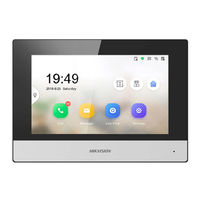
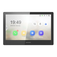
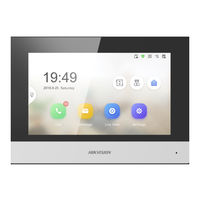
- DS-KH6320-TE1
Manuals and User Guides for HIKVISION DS-KH6320-TE1. We have 4 HIKVISION DS-KH6320-TE1 manuals available for free PDF download: Configuration Manual, Operation Manual
HIKVISION DS-KH6320-TE1 Configuration Manual (82 pages)
Network Indoor Station
Brand: HIKVISION
|
Category: Network Hardware
|
Size: 10.94 MB
Table of Contents
-
Table of Contents
8
-
Chapter 1 About this Manual
10
-
Chapter 2 Activation
11
-
Activate Via Ivms-4200 Client Software
11
-
-
Chapter 3 Local Operation
12
-
Quick Operation (for DS-KH6320EY-WTE2)
12
-
Quick Operation (for Normal Device)
17
-
Basic Settings
24
-
Set Indoor Station Network Parameters
25
-
Set Linked Device IP
26
-
Set Wi-Fi
27
-
Set Indoor Station no
28
-
SIP Settings
30
-
Add Camera
31
-
Zone and Alarm Settings
32
-
Password Settings
34
-
Change Admin Password
34
-
Security Settings
35
-
Modify Arm/Disarm Password
35
-
Modify Unlock/Duress Code
37
-
Synchronize Time
38
-
Sound Settings
38
-
Call Settings
39
-
Volume Settings
41
-
Via the Mobile Client
41
-
Link to the Mobile Client
41
-
Unlink the Account
42
-
System Settings
44
-
Output Settings
48
-
Device Information
49
-
-
Chapter 4 Remote Operation Via the Client Software
50
-
Device Management
50
-
Add Video Intercom Devices
50
-
Modify Network Information
52
-
System Configuration
53
-
Remote Configuration
53
-
System
53
-
Video Intercom
59
-
Network
69
-
Person Management
73
-
Organization Management
74
-
Person Management
75
-
-
Appendix A. Relevant Instructions for External Power Supply and Wiring of 2-Wire Video Intercom Products (2020-1-20)
78
-
Appendix B. Communication Matrix and Device Command
81
Advertisement
HIKVISION DS-KH6320-TE1 Configuration Manual (59 pages)
Video Intercom Indoor Station
Brand: HIKVISION
|
Category: Intercom System
|
Size: 8.7 MB
Table of Contents
-
Table of Contents
8
-
1 About this Manual
10
-
2 Local Operation
11
-
Activate Indoor Station
11
-
Quick Operation
12
-
Configuration Settings
15
-
Set Indoor Station Network Parameters
15
-
Set Linked Device IP
16
-
Set Indoor Station no
17
-
SIP Settings
18
-
Add Camera
19
-
Zone and Alarm Settings
19
-
-
Password Settings
21
-
Modify Unlock/Duress Code
22
-
Modify Admin Password
22
-
-
Synchronize Time
23
-
Sound Settings
24
-
Call Settings
24
-
Volume Settings
25
-
-
Link to the Mobile Client
25
-
Restore Indoor Station
26
-
System Maintenance
26
-
Device Information
28
-
Output Settings
28
-
-
3 Remote Operation Via the Client Software
30
-
Activate Device Remotely
30
-
Device Management
30
-
Add Video Intercom Devices
31
-
Modify Network Information
33
-
-
System Configuration
34
-
Remote Configuration
34
-
System
34
-
Video Intercom
40
-
Network
48
-
-
Person Management
52
-
Organization Management
53
-
Person Management
54
-
-
-
Communication Matrix and Device Command
58
HIKVISION DS-KH6320-TE1 Configuration Manual (47 pages)
Network Indoor Station
Brand: HIKVISION
|
Category: Control Panel
|
Size: 8.91 MB
Table of Contents
-
Table of Contents
5
-
1 Local Operation
7
-
Activate Indoor Station
7
-
Configuration Settings
7
-
Set Indoor Station Network Parameters
8
-
Set Linked Device IP
8
-
Set Indoor Station no
10
-
SIP Settings
11
-
Add Camera
12
-
Zone and Alarm Settings
12
-
-
Password Settings
14
-
Synchronize Time
15
-
Sound Settings
16
-
Call Settings
16
-
Volume Settings
18
-
-
Link to the Mobile Client
18
-
Restore Indoor Station
18
-
System Maintenance
19
-
Device Information
21
-
-
2 Remote Operation Via the Client Software
22
-
Activate Device Remotely
22
-
Device Management
22
-
Add Video Intercom Devices
23
-
Modify Network Information
25
-
-
System Configuration
26
-
Remote Configuration
26
-
System
26
-
Video Intercom
31
-
Network
38
-
-
Person and Card Management
41
-
Organization Management
41
-
Person Management
42
-
-
-
Communication Matrix and Device Command
46
Advertisement
HIKVISION DS-KH6320-TE1 Operation Manual (33 pages)
Network Indoor Station
Brand: HIKVISION
|
Category: Intercom System
|
Size: 3.69 MB
Advertisement
Related Products
-
HIKVISION DS-KH8350-WTE1
-
HIKVISION DS-PK00 series
-
HIKVISION DS-19A08-F/Kx
-
HIKVISION DS-PHA20-P
-
HIKVISION DS-PHA20-M
-
HIKVISION DS-PHA20-W2M
-
HIKVISION DS-PHA20-W2P
-
HIKVISION AX DS-PWA32-HGR
-
HIKVISION AX DS-PWA32-HS
-
HIKVISION AX DS-PWA32-HSR
HIKVISION Categories
![]()
Security Camera
DVR
Network Hardware
Intercom System
Security Sensors
More HIKVISION Manuals
Содержание
- Подключение и настройка ip домофона Hikvision
- Содержание:
- 1. Подключение ip домофона Hikvision
- 2. Настройка ip домофона Hikvision
- 3. Настройка монитора ip домофона Hikvision в программе IVMS — 4200
- 4. Выпуск карт ip домофона Hikvision
- 5. Подключение электро замка к ip домофону Hikvision
- 6. Подключение ip камеры
- 7. Добавление подчинённого монитора к основному монитору ip домофона
- 8. Настройка многоабонентской системы ip домофонии Hikvision
- Подключение комплекта домофона Hikvision DS-KV6113-WPE1 и DS-KH6320-WTE1
- Быстрая настройка IP-домофона и вызывной панели Hikvision
Подключение и настройка ip домофона Hikvision
Здесь подробная фото и видео инструкция о порядке подключения и настройки ip домофонов Hikvision. Подробнее о функционале ip домофонии читайте в статье Возможности ip видеодомофона Hikvision
Содержание:
Подключение ip домофона Hikvision
Настройка ip видеодомофона Hikvision
Выпуск карт ip домофона Hikvision
Подключение электро-механического замка к ip домофону Hikvision
Подключение ip камеры к ip домофону Hikvision
Добавление второго (подчинённого) монитора к основному монитору ip видеодомофона
Настройка многоабонентской системы ip домофонии Hikvision
Установка ip домофона Hikvision
Подключение ip домофона Hikvision к интернету
Подключение тревожных датчиков к ip домофону Hikvision
Часто задаваемые вопросы
1. Подключение ip домофона Hikvision
IP домофоны Hikvision поддерживают питание 12В и подключение по технологии PoE (Питание и данные подаются на устройство по одному сетевому кабелю Витая пара)
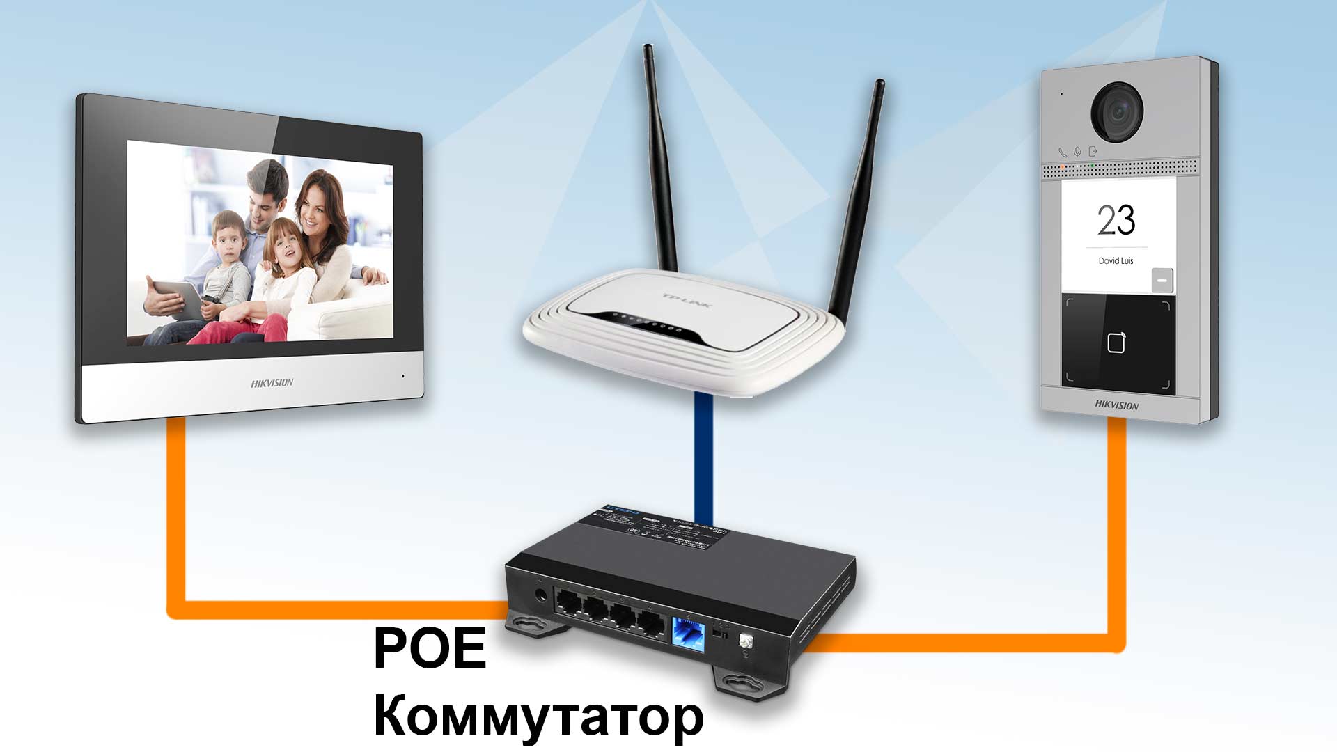
Рассмотрим вариант подключения системы ip домофонии по технологии РОЕ, т.к. такой способ наиболее удобный и практичный. Монитор ip домофона Hikvision и ip вызывную панель подключаем к РОЕ Коммутатору в свободный РОЕ порт. После объединяем порт Up-Link коммутатора с вашим интернет — роутером в вашу локальную компьютеную сеть. Если всё же ваш электрик сделал разводку витой пары по старой аналоговой схеме, соединив кабелем напрямую два сетевых устройства, не отчаевайтесь, сделать ip домофонию есть возможность и при такой разводке.
2. Настройка ip домофона Hikvision
В программе SADP активируем вызывную панель и монитор домофонной системы. После активации присваиваем каждому устройству ip адрес и шлюз (Gateway)
У ip вызывных панелей Hikvision есть свой web интерфейс, можете зайти на него через браузер Internet explorer и произвести настройку. Но у мониторов ip домофона Hikvision нет своего web интерфейса, поэтому настройку устройств можно производить локально в меню на экране сенсорного монитора или на компьютере в программе IVMS-4200.
Добавляем наши ip домофоны в клиент IVMS — 4200 логин и пароль — тот что задали при активации
Если в вашей системе ip домофонии будет более 2х устройств, например многоабонентская система, то для корректной работы советую всё же прошить каждое устройство последней прошивкой. Здесь найдете ссылки на последнюю прошивку для ip домофонов Hikvision (ссылки на версии прошивок ). После прошивки устройств Hikvision, что бы избежать остаточных багов, обязательно сбросте устройство до заводских настроек, кстати это правило касается не только ip домофонии.
Видео подключение и настройки ip домофона Hikvision
3. Настройка монитора ip домофона Hikvision в программе IVMS — 4200
Для настройки монитора ip домофона Hikvision в бесплатной программе IVMS — 4200 нужно добавить устройство в эту программу. Здесь же можно и произвести первичную активацию устройства, если вы не активировали вашу вызывную и монитор ранее в удобной и простой утилите SADP.
1. При выборе online device в нижнем поле отобразяться все ваши устройства в сети. Выбираем монитор и жмем добавить «Add».

2. В открывшемся диалоговом окне указываем любое имя устройству, ставим галочку синхронизировать время, указываем логин и пароль, тот который вы задали при активации.
3. Нажимаем шестеренку и попадаем в меню настроек. Основная логика заключается в том, что бы на мониторе ip домофона в меню настроек конфигурация связанной сети указать ip адрес вашей вызывной панели в строку Main Door Station ip adress.
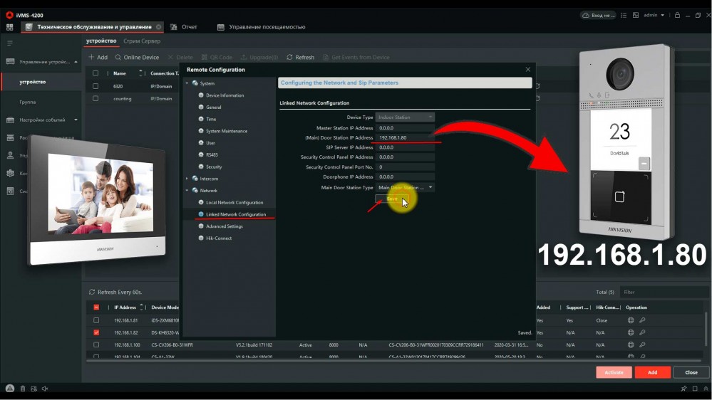
4. Всё, ip домофония связана и готова к работе, проверьте, нажав на кнопку вызова, должен пойти вызов на моиторе домофона.
4. Выпуск карт ip домофона Hikvision
ip домофоны Hikvision поддерживают стандарт карт Mifare.
Для выпуска карт необходимо сначала прислонить к считывателю мастер карту (в комплекте поставки). Затем программируем нужное количество карт для абонентов просто поочередно прикладывая карты к считывателю, завершаем выпуск карт повторно прислонив мастер карту к считывателю. Так же можно начать выпуск карт из меню web интерфейса самой вызывной панели. Такой способ удобен, если вы потеряли мастер карту от вызывной панели.
5. Подключение электро замка к ip домофону Hikvision
Для подключения к ip домофону Hikvision электро-механического замка необходимо плюс питания соединить с электро -механическим замком и синим кабелем вызывной панели, а минус соединить с зеленым кабелем вызывной панели .
6. Подключение ip камеры
Для подключения к ip домофону Hikvision цифровой камеры необходимо в мониторе видеодомофона зайти в настройки, далее -конфигурация, пароль администратора (пароль которй вы задали при активации монитора) . Затем — Устройство — добавить устройство — выбрать тип устройства — ip камера, затем в открывшемся окне присвойте любое имя для камеры, введите ip адрес камеры видеонаблюдения, а так же логин и пароль от камеры, жмем сохранить. Важно! Вторичный поток в ip камере должен быть выставлен кодеком H.264
7. Добавление подчинённого монитора к основному монитору ip домофона
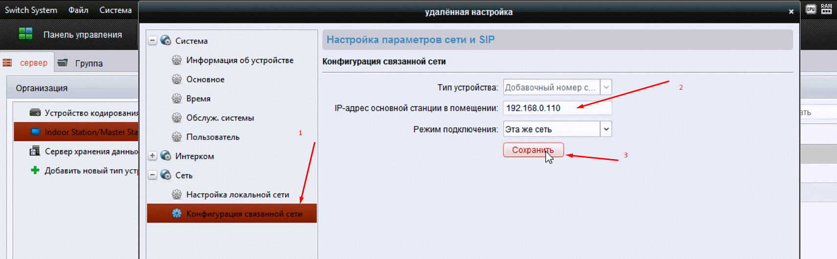
Для подключения второго, подчиненного монитора к основному монитору ip домофона Hikvision, нужно зайти в настройки добавочного монитора видеодомофона, далее — интерком, конфигурация идентификатора — тип устройства: Добавочный номер станции, ниже в строке указываем номер 1 — сохранить — перезагрузка устройства. После перезагрузки монитор стал добавочным. 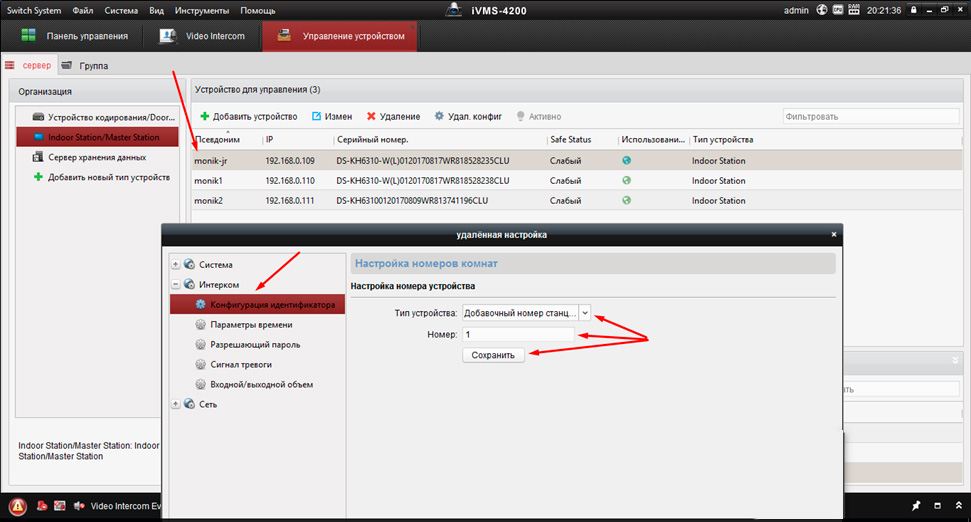
Затем повторно заходим на дополнительный монитор и в разделе сеть выбираем конфигурация связанной сети в строке ip адрес основной станции в помещении прописываем ip адрес главного монитора (не вызывной панели), в нашем случае это 192.168.0.110 , жмем сохранить.
8. Настройка многоабонентской системы ip домофонии Hikvision
Логика настройки многоабонентской ip домофонии Hikvision
Для всех мониторов:
1. указать №№ квартир (101, 102, 103 и т.д.)
2. указать ip адрес (главного) домофона (нашей многоабонетской ip вызывной панели)
Для главной многоабонетской ip вызывной панели:
1. Присвоить каждой кнопке № квартиры (101, 102, 103 и т.д.). Всё, настройка выполнена
Если же в системе есть подчиненные/межкомнатные вызывные панели ip домофонов hikvision, то
1. их необходимо перевести в режим не главной вызывной панели (Sub Villa Door Station), а после указать подчиненным панелям кто главная вызывная вызывная (прописать ip адрес Main Villa Door Station)
2. указать № квартиры (монитора — 101 или 102 или 103 и т.д.)
Ниже на видео пошагово как это сделать
Источник
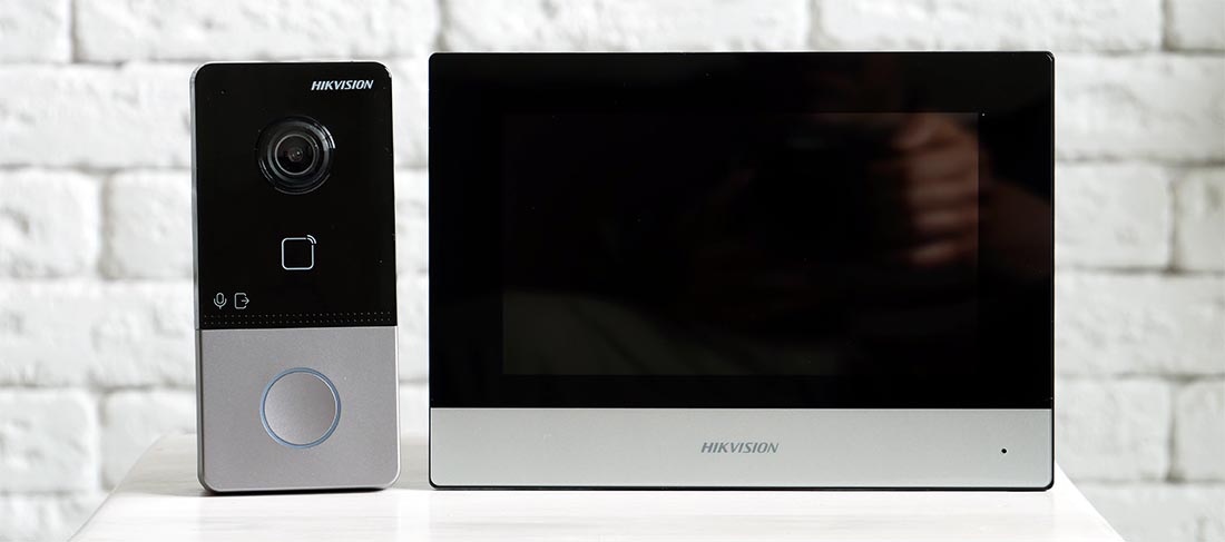
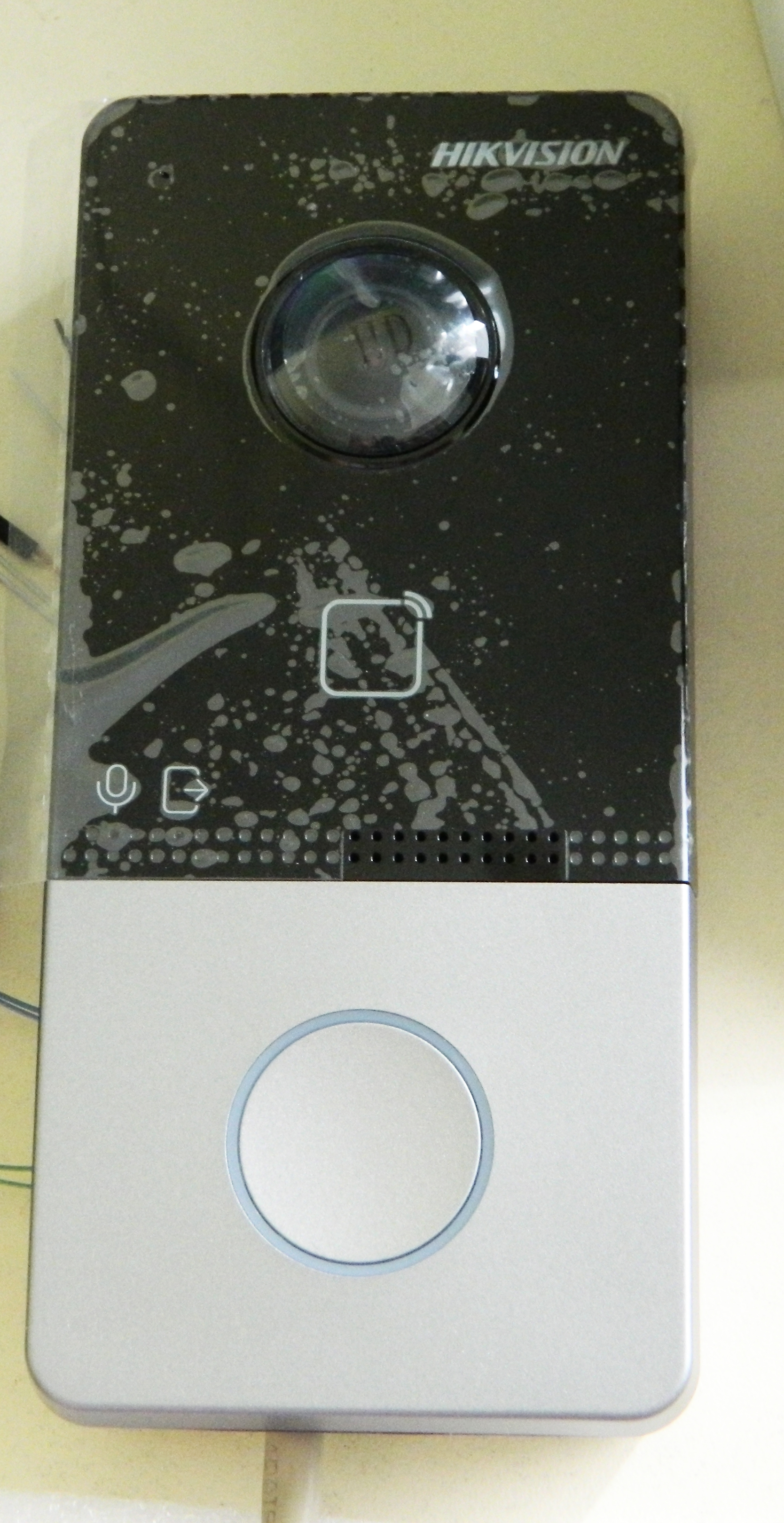
Подключение комплекта домофона Hikvision DS-KV6113-WPE1 и DS-KH6320-WTE1

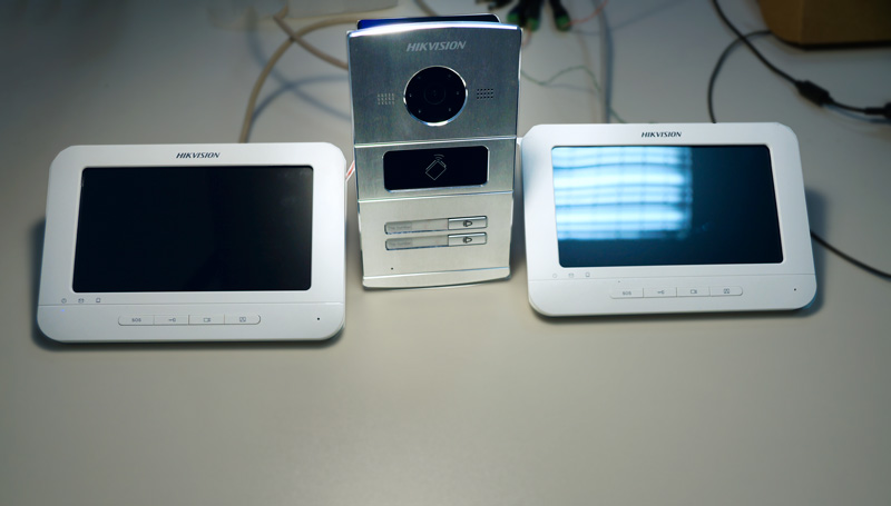
В этой статье мы будем подключать комплект домофонии Hikvision который включает в себя:
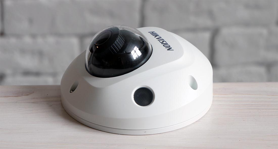
Камера видеонаблюдения Hikvision DS-2CD2523G0-IS
Для подключения и настройки нам понадобиться PoE коммутатор (например Dahua DH-PFS3006-4ET-60), утилита Hikvision SADP Tool и пару патч-кордов.
Подключаем домофон панель и камеру к РоЕ коммутатору, а сам РоЕ коммутатор к интернет роутеру.
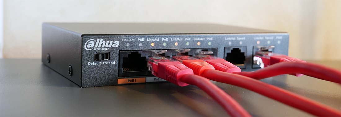
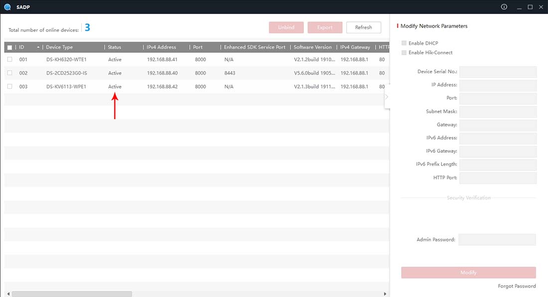
Устанавливаем и запускаем утилиту Hikvision SADP Tool и видим 3 наших устройства со статусом Inactive.
Этот статус говорит нам что устройства подключаются впервые или сброшены на заводские настройки.
Нам нужно активировать каждое устройство по инструкции —
После активации статусы на устройствах поменяются на Active.
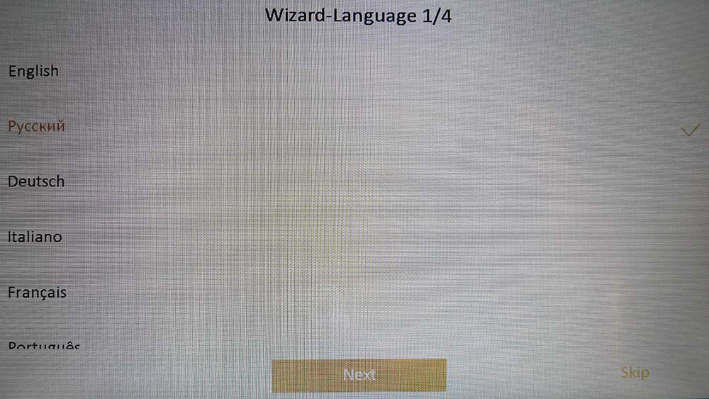
Вся последующая настройка выполняться с экрана домофона в 4 шага.
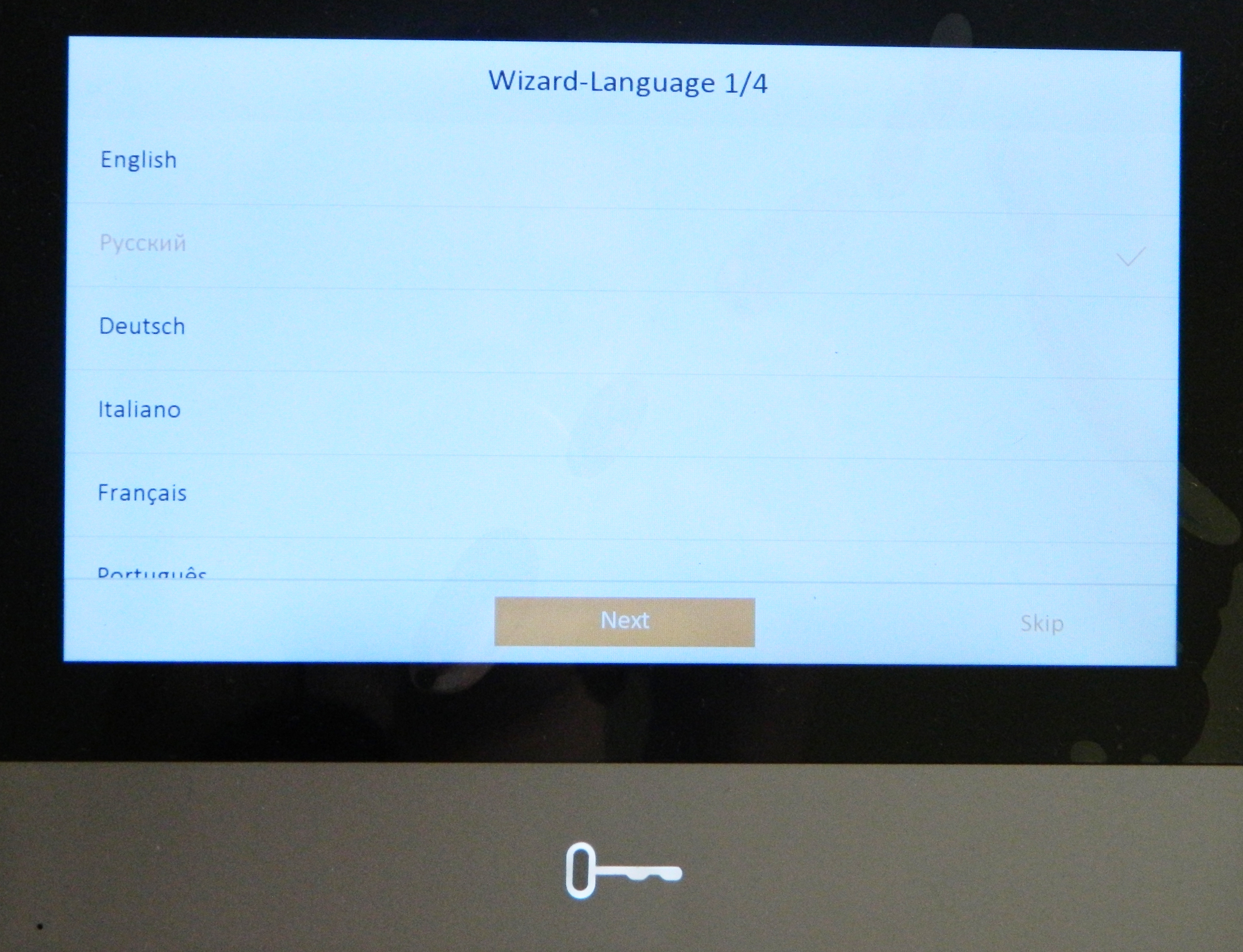
Шаг 1 — Выбираем язык Русский — нажимаем Nex
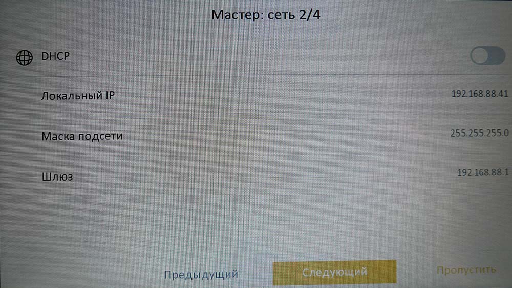
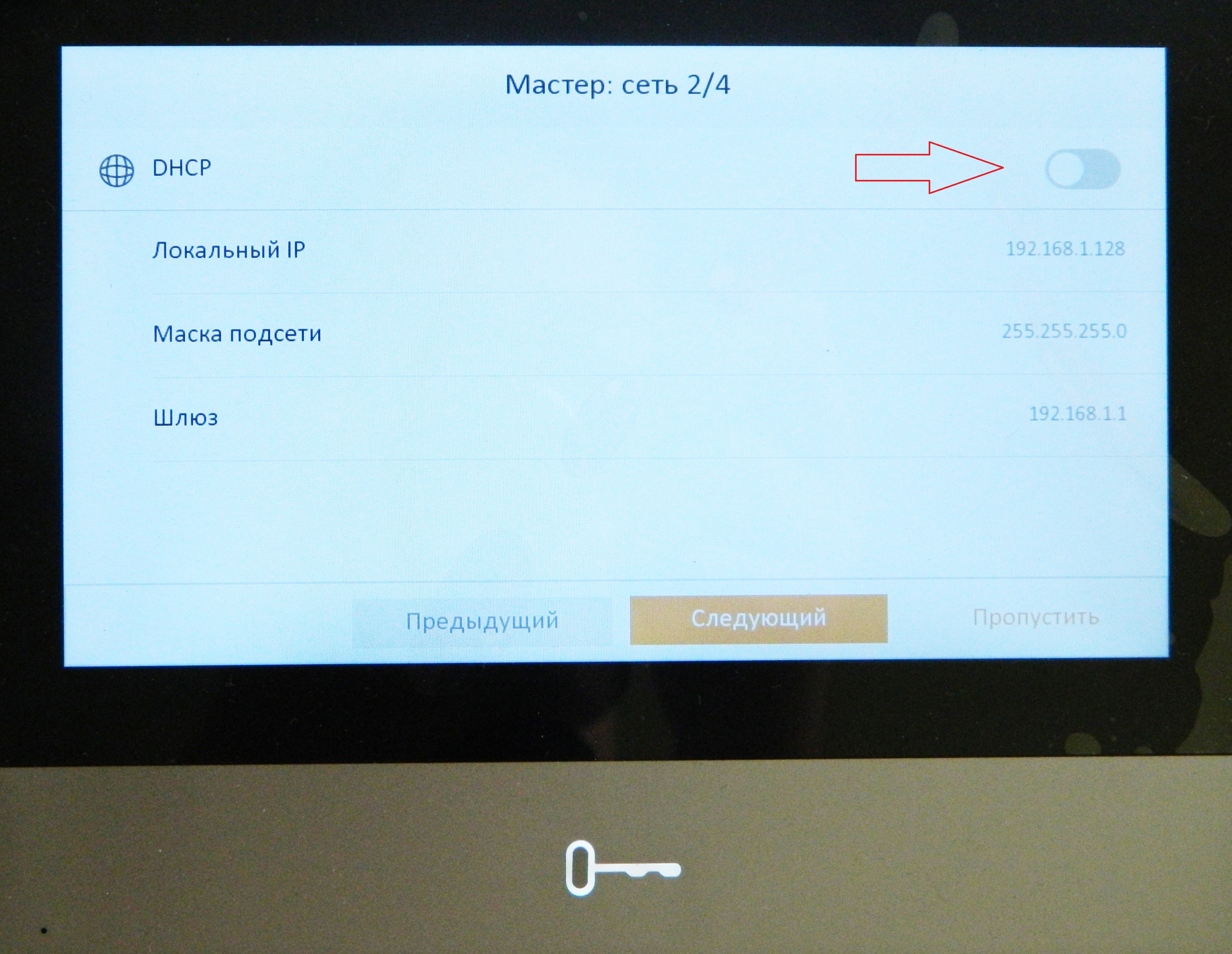
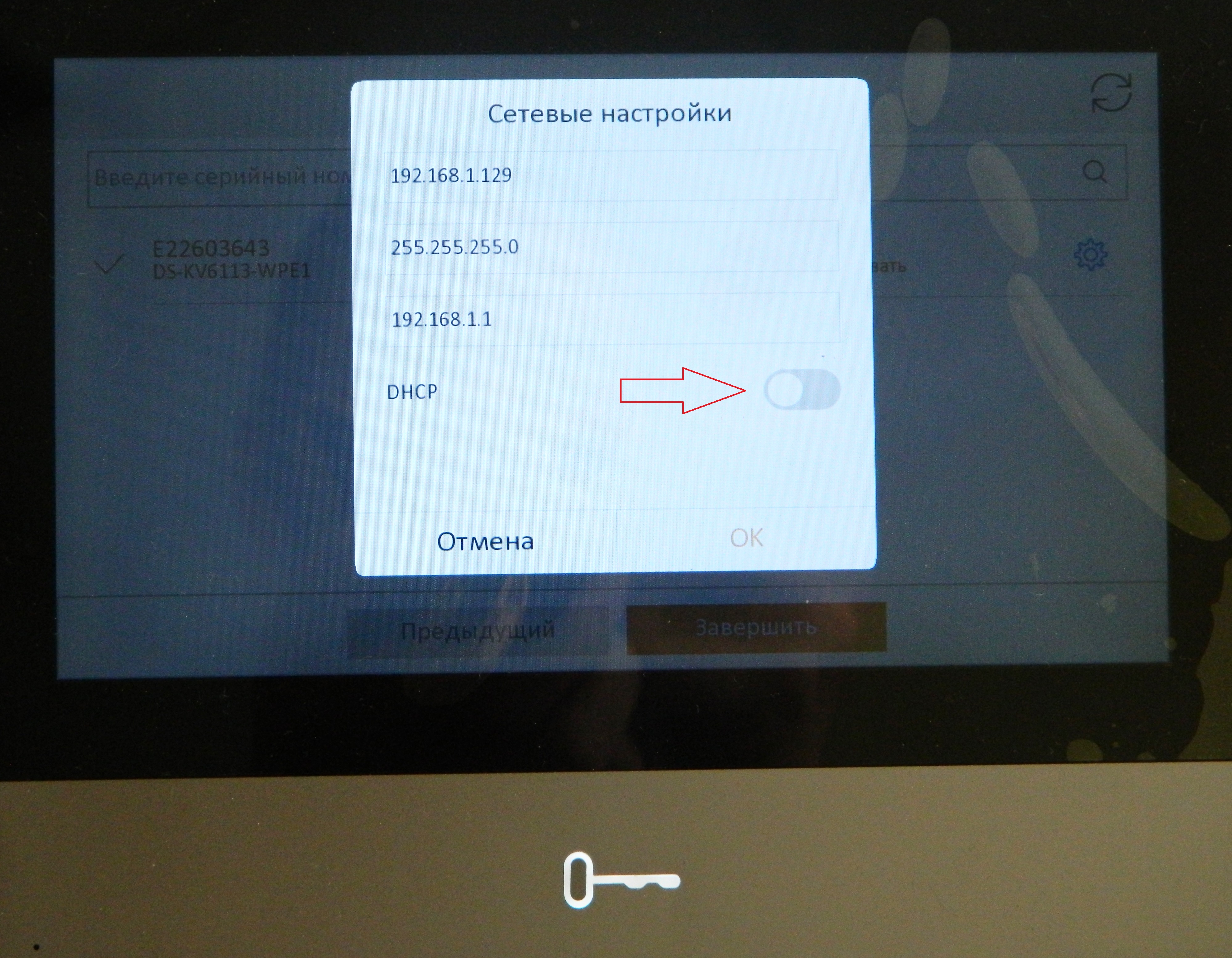
Шаг 2 — Активируем галочку DHCP (через 1-2 сек она вернётся обратно — это нормально) — нажимаем Следующий
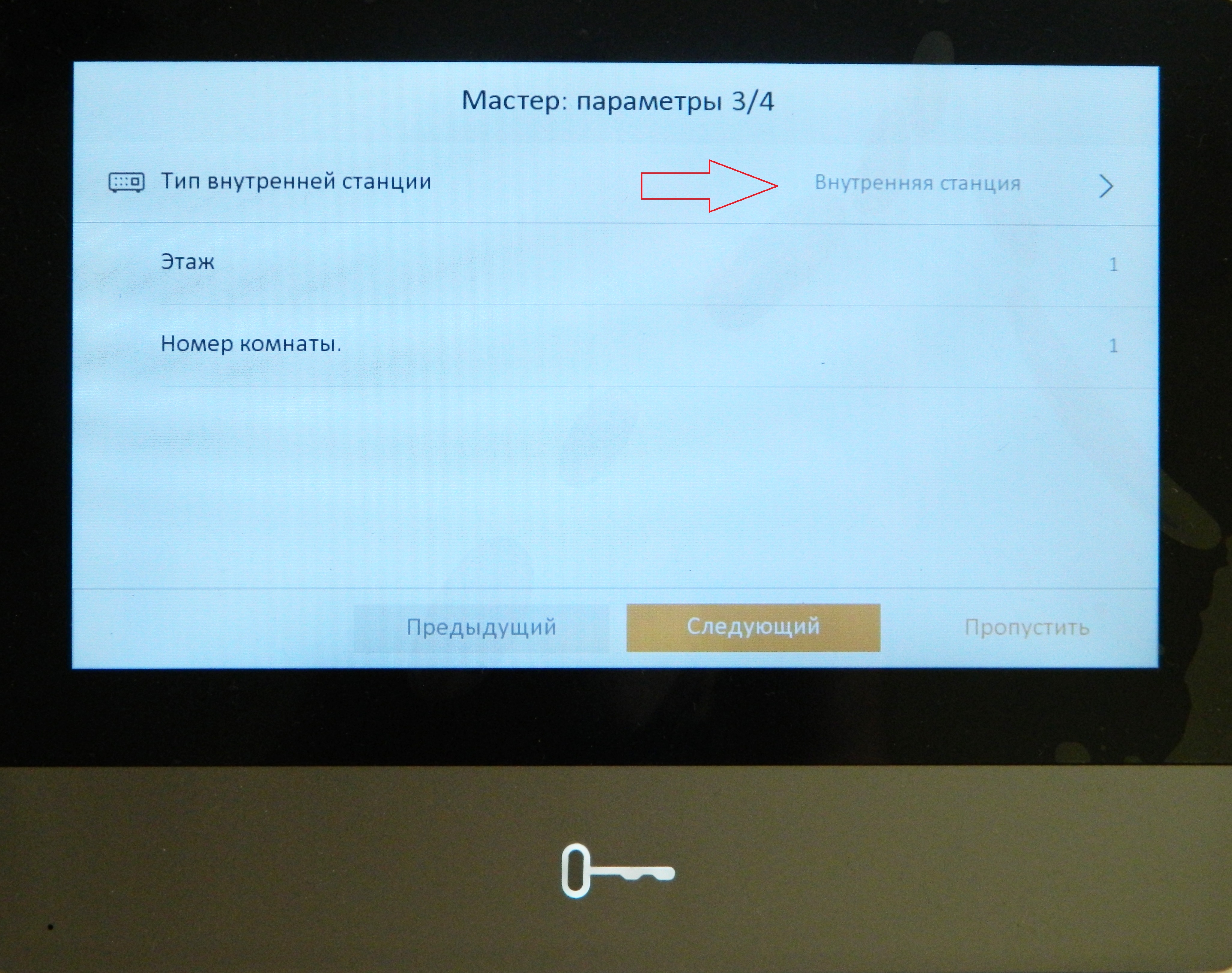
Шаг 3 — Если у Вас один домофон нажимаем — Следующий

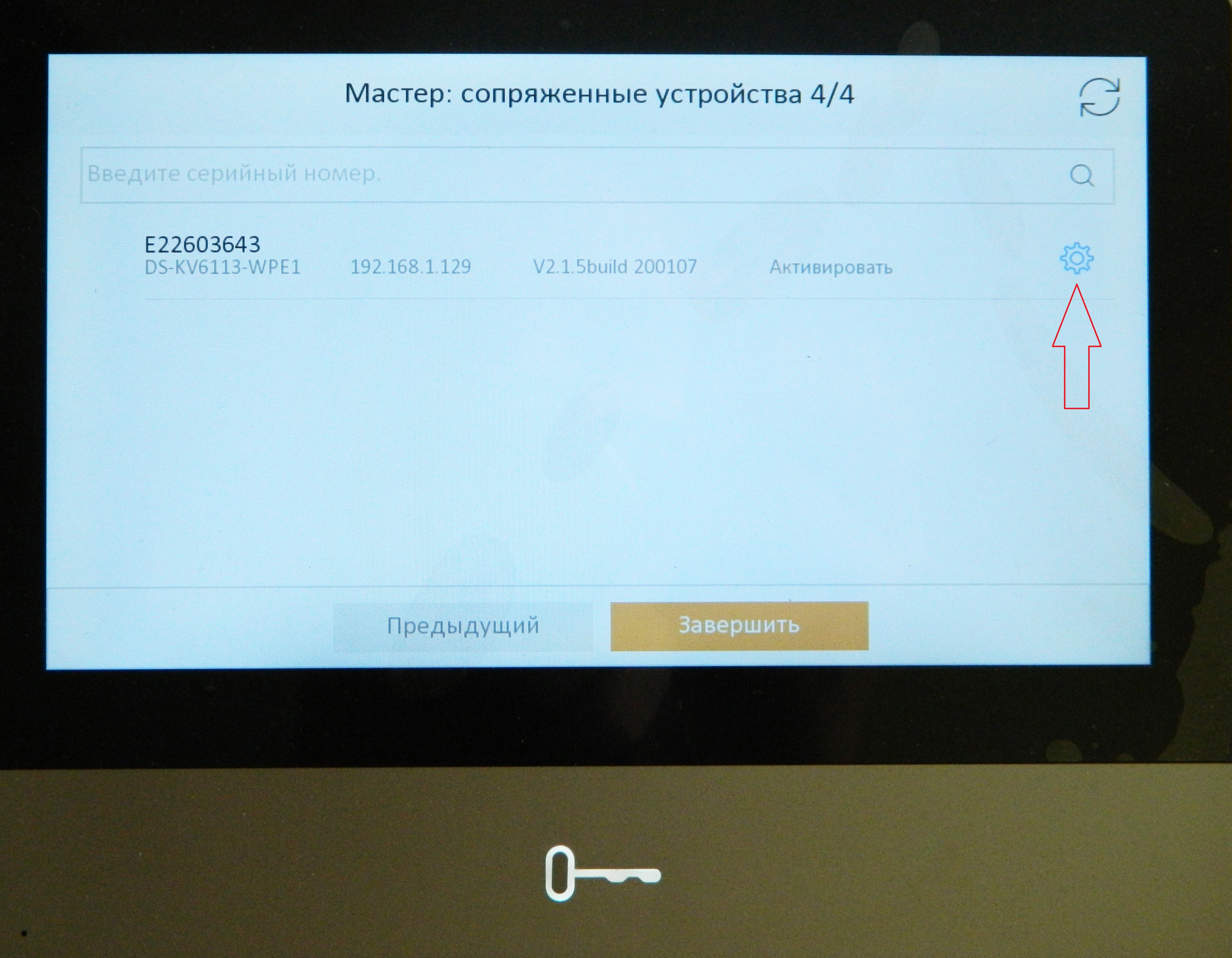
Шаг 4 — Отмечаем найденную панель и нажимаем Завершить.
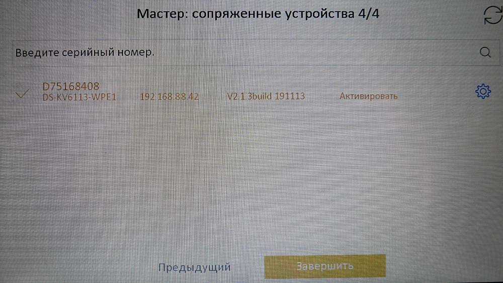
На этом подключение вызывной панели к домофону закончено.
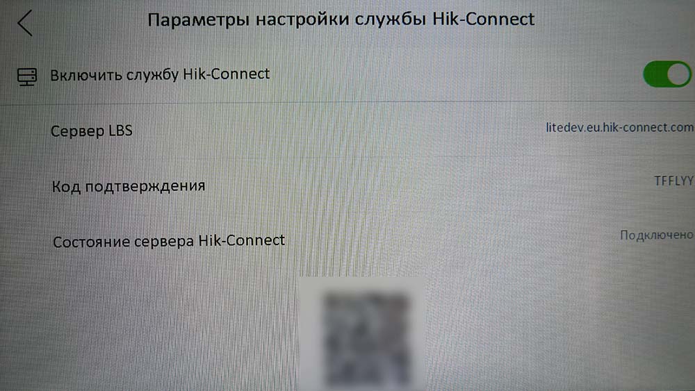
Настройка вызова на смартфон.
Для начала нужно включить службу Hik-Connect.
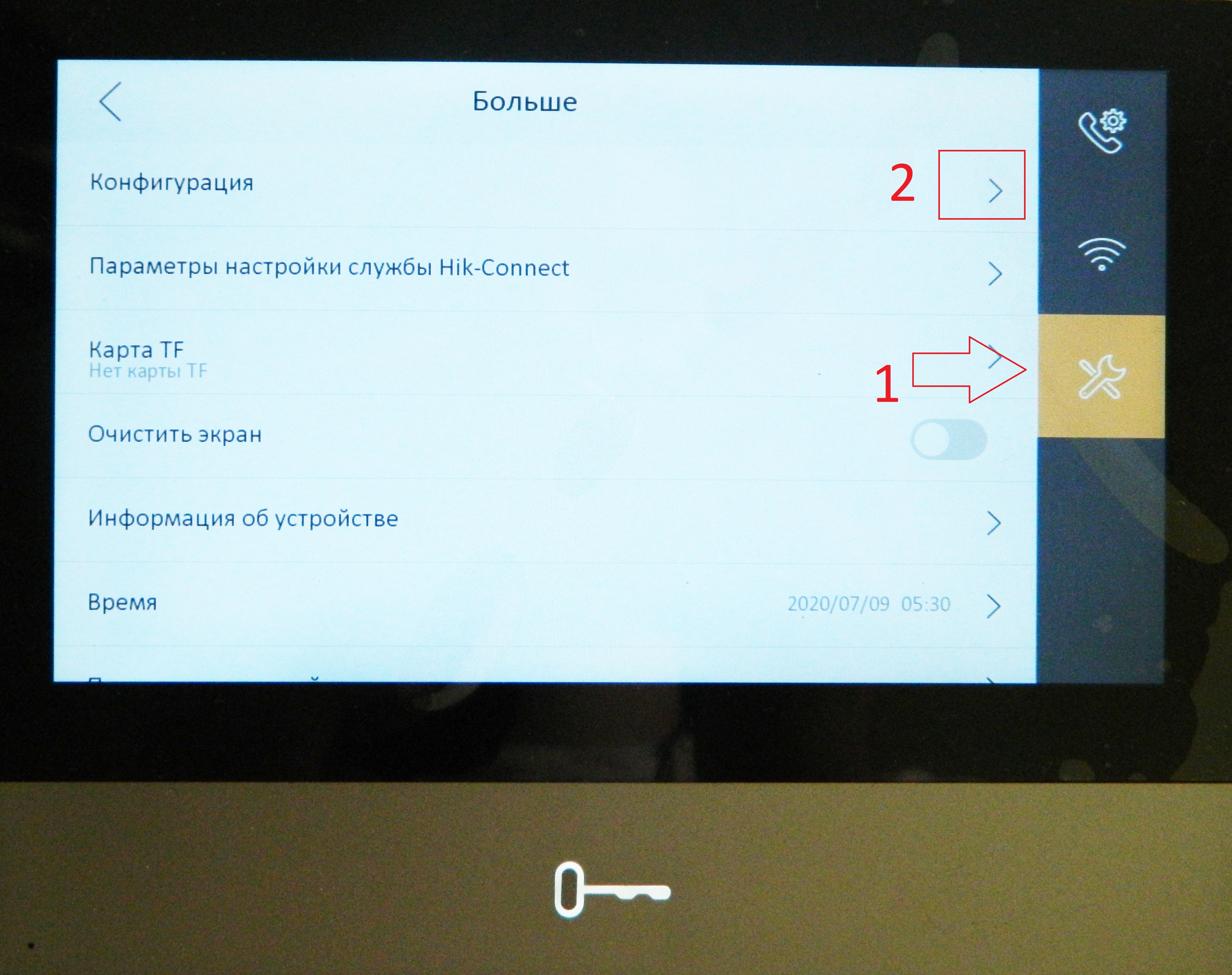
Заходим — Настройки — Больше — Параметры настройки службы Hik-Connect, включаем службу и проверяем статус — Подключено.
После этого заходим в приложение Hik-Connect на смартфоне, нажимаем Добавить устройство
Сканируем QR код который расположен внизу экрана меню настроек службы Hik-Connect домофона (или наклеен на самом домофоне)
Далее — Добавить
Вводим код подтверждения указанный в меню настроек службы Hik-Connect домофона, нажимаем — Ок.
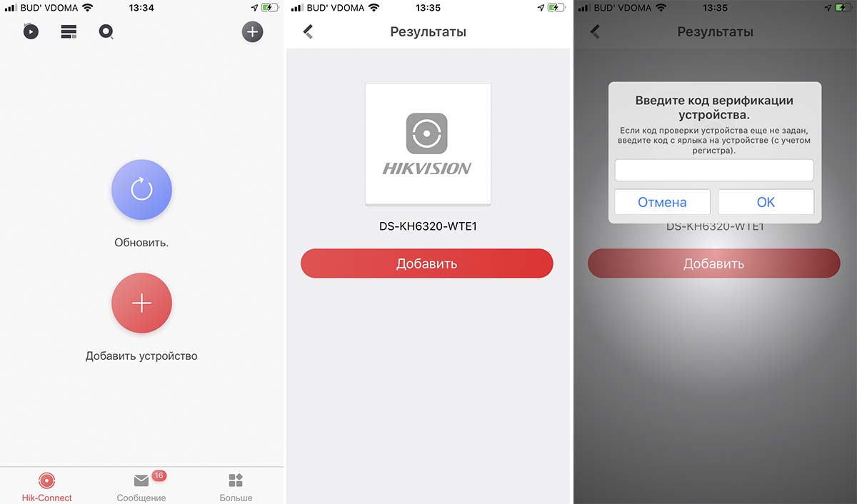
Через мобильное приложение можно пообщаться с посетителем и открыть дверь.
Надеемся данная статья была полезной. Если у Вас возникнут вопросы, пишите в чат или звоните в нашу техническую поддержку.
Источник
Быстрая настройка IP-домофона и вызывной панели Hikvision
Сегодня всё популярнее становится установка IP домофонии в частных домах, в виду своей возможности наблюдать за происходящим с помощью камеры с вызывной панели, прохода по карточкам RFID и не сложной самостоятельной первоначальной настройке.
Выбранные в данном проекте устройства (видеодомофн Hikvision IP DS-KH8350-WTE1 7 и вызывная панель DS-KV61X3-(W)PE1) обладают технологией PoE, что позволяет питать устройства по витой паре, подключим вызывную панель и домофон к PoE-свитчу. Также подключим электромеханический замок по схеме:
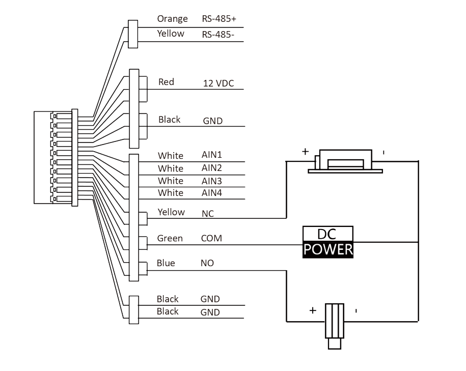
Где NO – выход реле дверного замка (нормально разомкнутый), а COM – общий интерфейс
При первом включении домофона появится мастер первоначальной настройки, на первом экране нужно задать пароль пользователя:
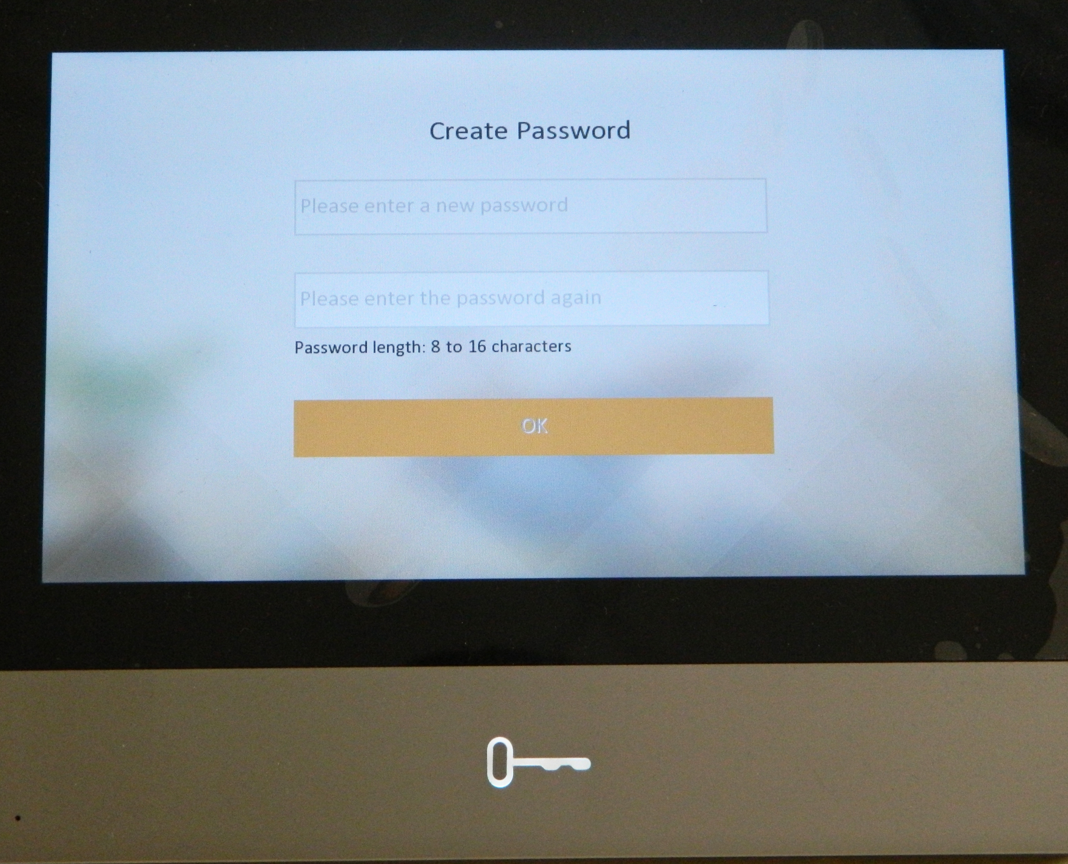
Первоначальная настройка состоит из четырёх этапов, первый – выбор языка интерфейса:
Вторым этапом является настройка сети, в верхней части экрана есть кнопка “DHCP”, предназначенная для автоматического получения настроек от роутера:
Третий этап отвечает за выбор типа внутренней станции, оставляем параметр «Внутренняя станция»:
На последнем, четвёртом этапе, остаётся добавить вызывную панель, которая автоматически отобразится в списке, если подключена к той же сети, что и домофон, для конфигурации нажмём шестерёнку в правом столбце, напротив наименования:
Здесь, также, есть кнопка “DHCP” для получения автоматических настроек сети:
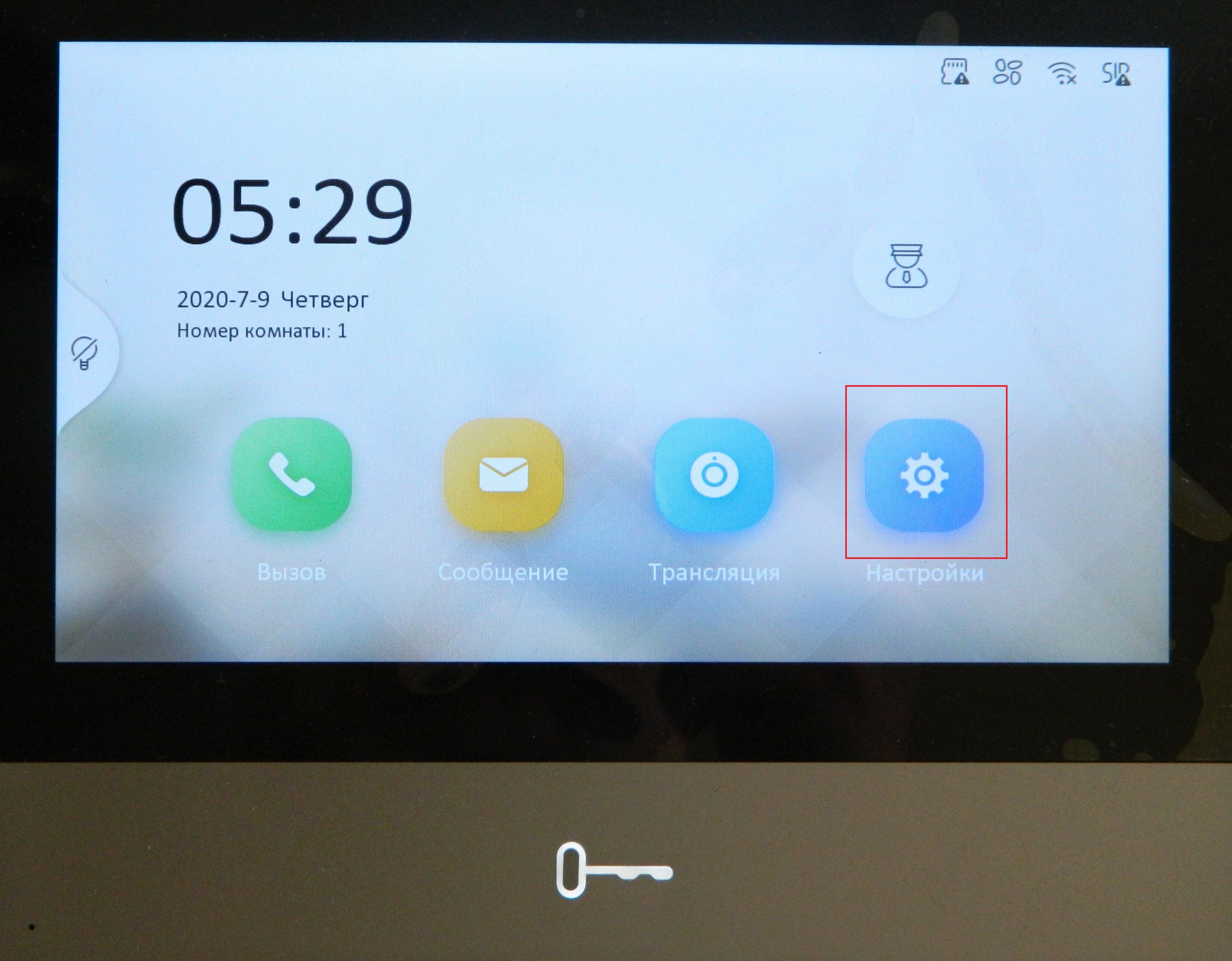
После мастера настроек вы попадёте на главный экран, откуда мы сразу переходим в настройки:
В правом столбце переходим в третий пункт и выбираем «Конфигурация» (пароль администратора – 888999):
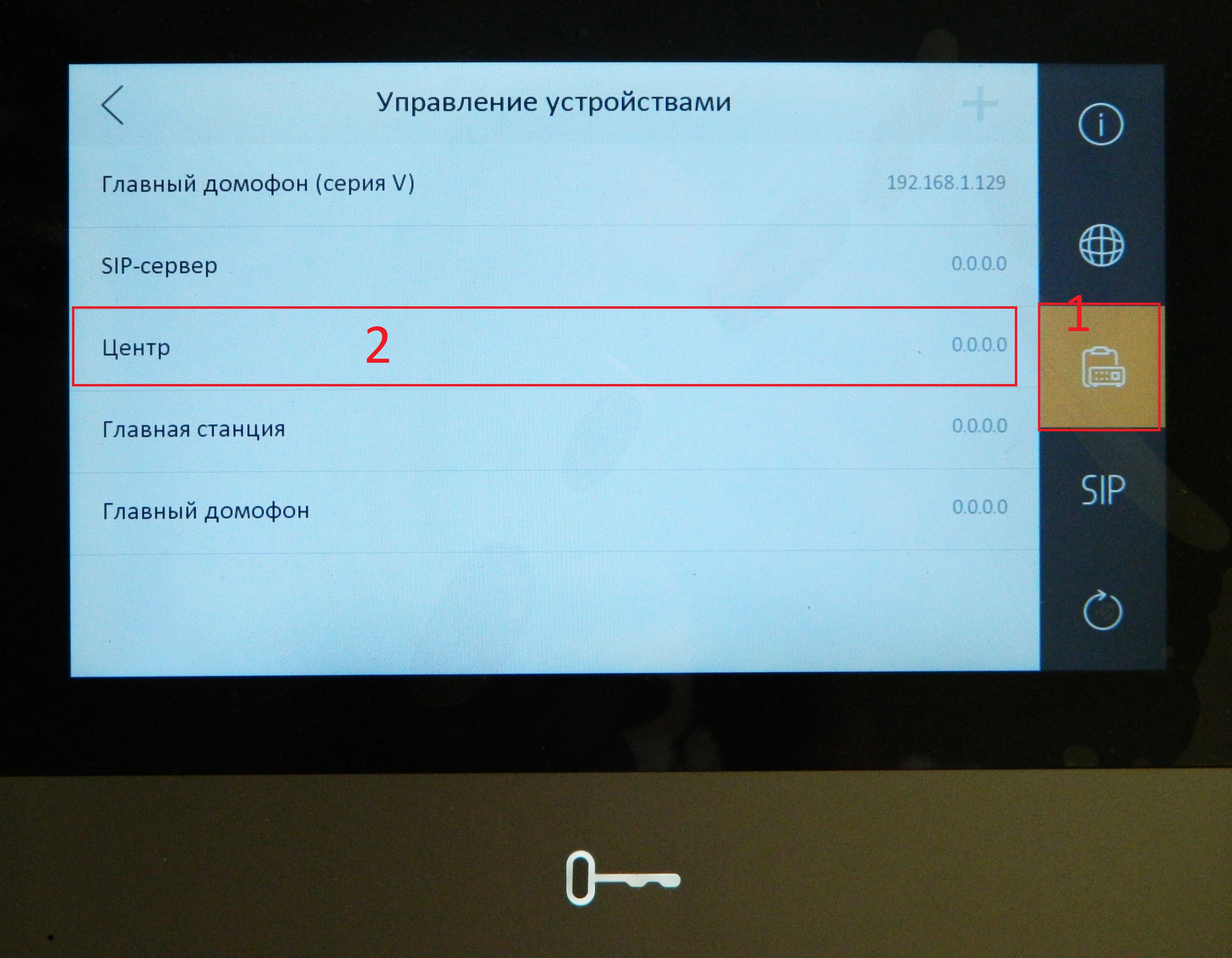
Далее переходим в 3 пункт меню «Управление устройствами» и прописываем в настройке «Центр» IP-адрес домофона:
Для теста нажмём на вызывной панели кнопку вызова, расположенную снизу:
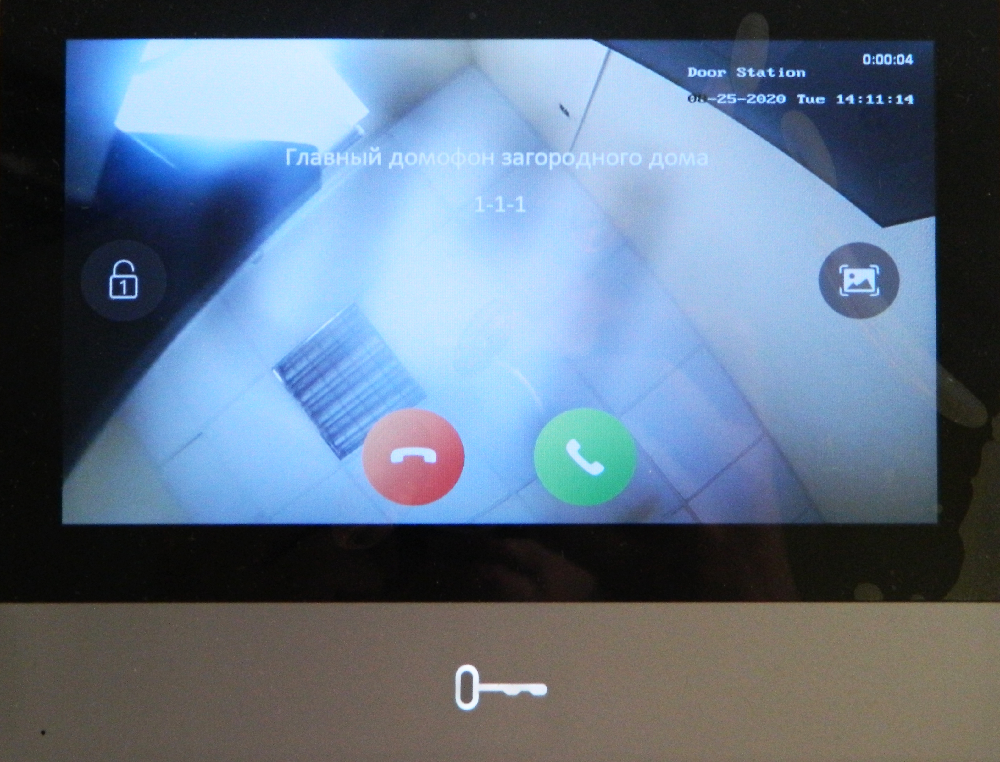
Если всё настроено верно, то на домофон должен прийти вызов с отображением происходящего с камеры панели, при вызове Вы можете принять или отклонить вызов, также в левой части экрана находится кнопка разблокирования двери, в правой части кнопка для создания скриншота:
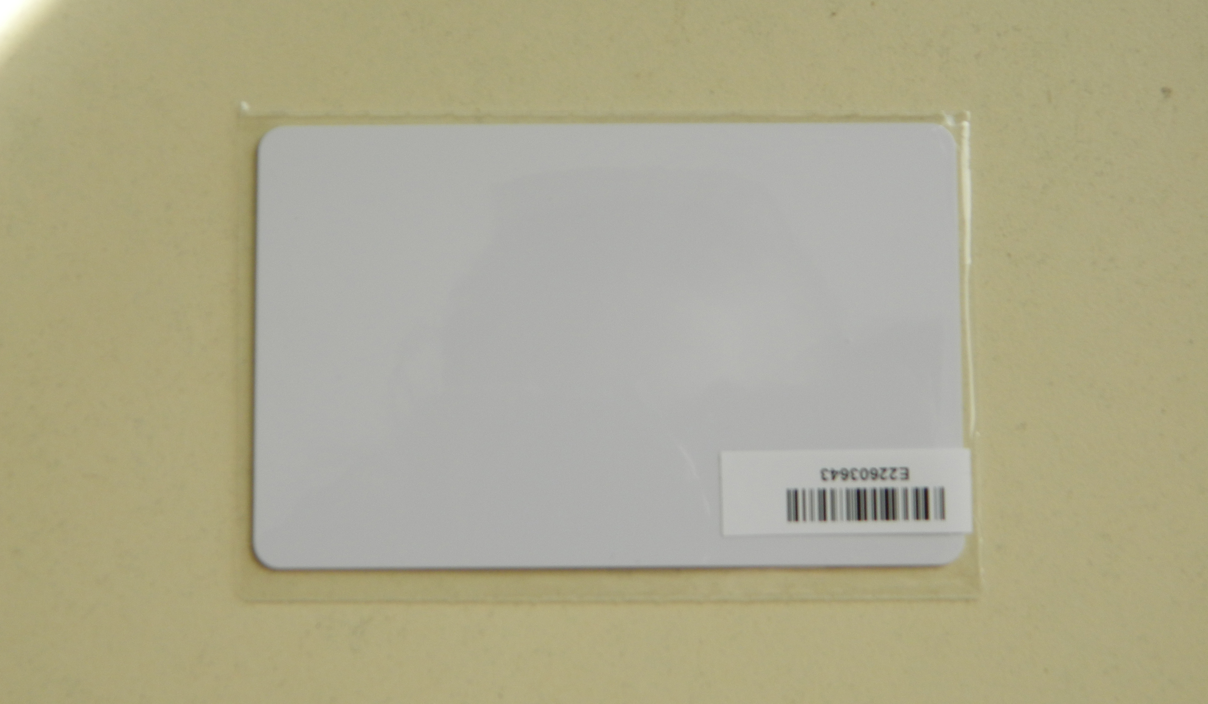
Для добавления карточек нужно приложить к считывателю сначала карточку «мастер-ключ» из комплекта со считывателем или вызывной панелью, после чего приложить программируемый ключ (формат Mifare)
Источник

Network Indoor Station
Configuration Guide
Network Indoor Station Configuration Guide
Legal Information
©2020 Hangzhou Hikvision Digital Technology Co., Ltd. All rights reserved.
About this Manual
The Manual includes instructions for using and managing the Product.
Pictures, charts, images and all other information hereinafter are for
description and explanation only. The information contained in the Manual
is subject to change, without notice, due to firmware updates or other
reasons. Please find the latest version of this Manual at the Hikvision
website ( https://www.hikvision.com/ ).
Please use this Manual with the guidance and assistance of professionals
trained in supporting the Product.
Trademarks
and other Hikvision's trademarks and logos are the
properties of Hikvision in various jurisdictions.
Other trademarks and logos mentioned are the properties of their
respective owners.
Disclaimer
TO THE MAXIMUM EXTENT PERMITTED BY APPLICABLE LAW, THIS MANUAL
AND THE PRODUCT DESCRIBED, WITH ITS HARDWARE, SOFTWARE AND
FIRMWARE, ARE PROVIDED “AS IS” AND “WITH ALL FAULTS AND ERRORS”.
HIKVISION MAKES NO WARRANTIES, EXPRESS OR IMPLIED, INCLUDING
WITHOUT LIMITATION, MERCHANTABILITY, SATISFACTORY QUALITY, OR
FITNESS FOR A PARTICULAR PURPOSE. THE USE OF THE PRODUCT BY YOU IS
AT YOUR OWN RISK. IN NO EVENT WILL HIKVISION BE LIABLE TO YOU FOR
ANY SPECIAL, CONSEQUENTIAL, INCIDENTAL, OR INDIRECT DAMAGES,
INCLUDING, AMONG OTHERS, DAMAGES FOR LOSS OF BUSINESS PROFITS,
BUSINESS INTERRUPTION, OR LOSS OF DATA, CORRUPTION OF SYSTEMS, OR
LOSS OF DOCUMENTATION, WHETHER BASED ON BREACH OF CONTRACT,
TORT (INCLUDING NEGLIGENCE), PRODUCT LIABILITY, OR OTHERWISE, IN
i
Network Indoor Station Configuration Guide
CONNECTION WITH THE USE OF THE PRODUCT, EVEN IF HIKVISION HAS
BEEN ADVISED OF THE POSSIBILITY OF SUCH DAMAGES OR LOSS.
YOU ACKNOWLEDGE THAT THE NATURE OF INTERNET PROVIDES FOR
INHERENT SECURITY RISKS, AND HIKVISION SHALL NOT TAKE ANY
RESPONSIBILITIES FOR ABNORMAL OPERATION, PRIVACY LEAKAGE OR
OTHER DAMAGES RESULTING FROM CYBER-ATTACK, HACKER ATTACK, VIRUS
INSPECTION, OR OTHER INTERNET SECURITY RISKS; HOWEVER, HIKVISION
WILL PROVIDE TIMELY TECHNICAL SUPPORT IF REQUIRED.
YOU AGREE TO USE THIS PRODUCT IN COMPLIANCE WITH ALL APPLICABLE
LAWS, AND YOU ARE SOLELY RESPONSIBLE FOR ENSURING THAT YOUR USE
CONFORMS TO THE APPLICABLE LAW. ESPECIALLY, YOU ARE RESPONSIBLE,
FOR USING THIS PRODUCT IN A MANNER THAT DOES NOT INFRINGE ON THE
RIGHTS OF THIRD PARTIES, INCLUDING WITHOUT LIMITATION, RIGHTS OF
PUBLICITY, INTELLECTUAL PROPERTY RIGHTS, OR DATA PROTECTION AND
OTHER PRIVACY RIGHTS. YOU SHALL NOT USE THIS PRODUCT FOR ANY
PROHIBITED END-USES, INCLUDING THE DEVELOPMENT OR PRODUCTION
OF WEAPONS OF MASS DESTRUCTION, THE DEVELOPMENT OR
PRODUCTION OF CHEMICAL OR BIOLOGICAL WEAPONS, ANY ACTIVITIES IN
THE CONTEXT RELATED TO ANY NUCLEAR EXPLOSIVE OR UNSAFE NUCLEAR
FUEL-CYCLE, OR IN SUPPORT OF HUMAN RIGHTS ABUSES.
IN THE EVENT OF ANY CONFLICTS BETWEEN THIS MANUAL AND THE
APPLICABLE LAW, THE LATER PREVAILS.
ii
Network Indoor Station Configuration Guide
Symbol Conventions
The symbols that may be found in this document are defined as follows.
Symbol
Danger
Caution
Note
Description
Indicates a hazardous situation which, if not avoided, will or
could result in death or serious injury.
Indicates a potentially hazardous situation which, if not
avoided, could result in equipment damage, data loss,
performance degradation, or unexpected results.
Provides additional information to emphasize or
supplement important points of the main text.
iii
Network Indoor Station Configuration Guide
Contents
1 Local Operation .......................................................................................... 1
1.1 Activate Indoor Station ..................................................................................... 1
1.2 Configuration Settings ....................................................................................... 1
1.2.1 Set Indoor Station Network Parameters ................................................... 2
1.2.2 Set Linked Device IP .................................................................................. 2
1.2.3 Set Indoor Station No. .............................................................................. 4
1.2.4 SIP Settings ............................................................................................... 5
1.2.5 Add Camera .............................................................................................. 6
1.2.6 Zone and Alarm Settings ........................................................................... 6
1.3 Password Settings ............................................................................................. 8
1.4 Synchronize Time .............................................................................................. 9
1.5 Sound Settings ................................................................................................. 10
1.5.1 Call Settings ............................................................................................ 10
1.5.2 Volume Settings ...................................................................................... 12
1.6 Link to the Mobile Client ................................................................................. 12
1.7 Restore Indoor Station .................................................................................... 12
1.8 System Maintenance ....................................................................................... 13
1.9 Device Information .......................................................................................... 15
2 Remote Operation via the client software ............................................... 16
2.1 Activate Device Remotely ............................................................................... 16
2.2 Device Management ....................................................................................... 16
2.2.1 Add Video Intercom Devices .................................................................. 17
iv
Network Indoor Station Configuration Guide
2.2.2 Modify Network Information ................................................................. 19
2.3 System Configuration ...................................................................................... 20
2.4 Remote Configuration ..................................................................................... 20
2.4.1 System .................................................................................................... 20
2.4.2 Video Intercom ....................................................................................... 25
2.4.3 Network .................................................................................................. 32
2.5 Person and Card Management ........................................................................ 35
2.5.1 Organization Management ..................................................................... 35
2.5.2 Person Management .............................................................................. 36
A. Communication Matrix and Device Command ....................................... 40
v
Network Indoor Station Configuration Guide
1 Local Operation
1.1 Activate Indoor Station
You can only configure and operate the indoor station after creating a password for
the device activation.
Steps
1. Power on the device. It will enter the activation page automatically.
Figure 1-1 Activation Page
2. Create a password and confirm it.
3. Tap OK to activate the indoor station.
Note
We highly recommend you to create a strong password of your own choosing
(using a minimum of 8 characters, including at least three kinds of following
categories: upper case letters, lower case letters, numbers, and special
characters) in order to increase the security of your product. And we
recommend you change your password regularly, especially in the high security
system, changing the password monthly or weekly can better protect your
product.
1.2 Configuration Settings
1
Network Indoor Station Configuration Guide
Configuration settings is required before starting using the indoor station. It is
necessary to set the indoor station network, room No., linked devices, device time
display, and so on.
1.2.1 Set Indoor Station Network Parameters
Network connection is mandatory for the use of the indoor station. Set the network
parameters after activating the indoor station. Only when the IP address of the
indoor station is in the same network segment as other devices, it can work properly
in the same system.
Steps
Note
The default IP address of the indoor station is 192.0.0.64.
Two ways are available for you to set IP address: DHCP, and set IP address manually.
1. Tap Settings →
2. Tap
→ Configuration , and enter admin (activation) password.
to enter the network settings page.
Figure 1-2 Network Settings
3. Set the network parameters.
- Enable DHCP, and the system can assign an IP address of the indoor station
automatically.
- Disable the DHCP function, and set the IP address manually. You should set
the device IP address, the gateway, the DNS address.
1.2.2 Set Linked Device IP
2
Network Indoor Station Configuration Guide
Linked network parameters refers to the network parameters of devices (like door
station, doorphone, master station, center, etc.), to which the indoor station is
linked. Linked devices for the indoor station refers to door station, center, master
station, and doorphone.
With the private SIP protocol, intercom can be realized only when all these devices
are in the same network segment with the indoor station.
With the standard SIP protocol, intercom can be realized when all these devices
support the standard SIP protocol.
Steps
Note
•
The doorphone does not support adding with the standard SIP protocol.
•
Here take door station network settings as example.
1. Tap Settings →
2. Tap
→ Configuration , and enter admin (activation) password.
to enter the device management page.
Figure 1-3 Device Management Page
3. Tap Indoor Extension and select a connect indoor extension.
4. Tap Main Door Station to pop up the device information dialog.
3
Network Indoor Station Configuration Guide
Figure 1-4 Device Information
Restore the door station via indoor station.
Tap
to restore the parameters of the door station.
Modify the IP address of the linked door station.
Tap
to edit the IP address of door station.
5. Select the device to link. Edit the network parameters.
1.2.3 Set Indoor Station No.
Indoor station No. and the indoor extension No. are numbers, which can be dialed
by other devices to call the indoor station and the indoor extension in an intercom
system. The indoor station No., is composed of the floor No. and the room No.
The indoor extension No. Should be a numeric from 1 to 5.
Up to 5 indoor extensions can be set for 1 indoor station.
Steps
1. Tap Settings →
2. Tap
→ Configuration , and enter admin (activation) password.
to enter the indoor station settings page.
4
Network Indoor Station Configuration Guide
Figure 1-5 Set Indoor Station Information
3. Select Indoor Station Type from Indoor Station or Indoor Extension according to
your actual needs.
- Indoor Station: You can set the indoor station's room information, including
the room name, community No., building No., Unit No., floor, and room No.,
the live view duration, the SIP register password, and the SIP parameters.
- Indoor Extension: You can set the indoor extension's room information,
including the room name and the extension No., live view duration, and the
SIP register password.
4. Tap Room Information and set room name, community No., building No., unit
No., floor No., and room No. according to your actual needs.
1.2.4 SIP Settings
Devices can communicate with each other via SIP protocol. You create set the SIP
register password, enable standard SIP and set VIOP account.
Steps
1. Tap Settings →
→ Configuration , and enter admin (activation) password.
2. Set SIP register password.
1) Tap SIP register password.
2) Create a new SIP register password and confirm the password.
3) Tap OK.
3. Optional: Enable standard SIP.
1) Tap SIP Settings.
5
Network Indoor Station Configuration Guide
2) Enable Enable Standard SIP.
3) Tap VOIP Account Settings and configure the account information, including
the user name, the phone number, the registered user name, the password,
the domain, the port No,, and the expiration date.
Note
Up to 32 characters are allowed in the user name.
1.2.5 Add Camera
Steps
1. Tap Settings →
2. Tap
→ Configuration , and enter admin (activation) password.
to enter the device management page.
3. Tap + to pop up the dialog box.
4. Select HIK Protocol and you can add the camera depended on the HIK protocol.
5. Enter the device name and IP address.
6. Enter the device user name and the password of the camera.
7. Exit the page to save the settings.
1.2.6 Zone and Alarm Settings
Zone Settings
You can set the zone type, alarm type and delay time and other parameters of 8
zones.
Before You Start
Tap Settings →
→ Shortcut Settings , and enable Alarm.
Steps
Note
Arming status page and zone settings page are hidden by default. You should enable
alarm function first.
1. Tap Settings →
→ Zone Settings to enter the zone settings page.
6
Network Indoor Station Configuration Guide
Figure 1-6 Zone Settings
2. Press a zone to pop up the zone editing dialogue box.
3. Set the zone type, alarm type, status of arming status, entering delay, and exiting
delay.
4. Tap OK to save the settings.
Note
•
7 zone types are selectable: Panic Button, Door Magnetic, Smoke Detector,
Active Infrared, Passive Infrared, Gas Detector, and Doorbell.
•
3 alarm types are selectable: 24h Alarm, Instant Alarm, and Delay Alarm.
Set the alarm type as 24h alarm, and the zone will be armed for 24h.
Set the alarm type as instant alarm, and the zone will alarm once it's
triggered.
Set the alarm type as delay alarm, and you should set the entering delay
duration and exiting delay duration.
•
Both the entering delay duration and the exiting delay duration are from 30s
to 60s.
•
For Gas Detector and Smoke Detector, the alarm type is set as default 24h
alarm. The alarm type of them can not be changed.
Arming Mode Settings
4 arming modes can be configured: stay mode, away mode, sleeping mode and
custom mode.
7
Network Indoor Station Configuration Guide
Before You Start
Tap Settings → → Shortcut Settings to enable Alarm.
Steps
Note
On the home page, the arming status function and zone settings function are hidden
by default. You should enable the alarm function first.
1. Back to the home page, tap Settings →
mode settings page.
→ Scene Settings to enter the arming
2. Tap Stay Mode, Away Mode, Sleeping Mode, or Custom to enter the page.
Figure 1-7 Arming Mode Settings
3. Arm the selected zone.
Note
•
Zones are configurable on the arming mode page.
•
24H alarm zone including smoke detector zone and gas detector zone will be
triggered even if they are disabled.
•
Arming mode settings should be configured with the settings of arming
status on the user page of the device.
1.3 Password Settings
8
Network Indoor Station Configuration Guide
You can create and edit the arm/disarm password, duress code and unlock password
of the indoor station.
Steps
1. Tap Settings →
→ Password to enter the password settings page.
2. Tap Arm/Disarm, Unlock or Duress Code to pop up the password settings dialog
box.
Arm/Disarm
The password is for arming or disarming the zone for the indoor station.
Note
By default, the Arm/Disarm page is hidden. Tap Settings →
→ Shortcut
Settings and enable Alarm. And the Arm/Disarm page will be displayed.
Unlock
Create the indoor station's unlock password. If the device has connected to a
lock, enter the password to unlock.
Duress Code
When you are hijacked and forced to open the door, you can enter the
duress code. An alarm will be triggered to notify the management center
secretly.
Note
The duress code and the unlock password cannot be the same.
3. Enter the old password.
4. Create a new password and confirm it.
5. Tap OK to save the settings.
1.4 Synchronize Time
Steps
1. Tap Settings →
→ Time and Date → Sync Time to enter the time
synchronization page.
9
Network Indoor Station Configuration Guide
Figure 1-8 Time Synchronization
2. Enable Enable NTP.
3. Set the synchronizing interval, enter the IP address/domain of NTP server and
port No., and select the time zone.
Note
•
The default unit of synchronizing interval is minute.
•
The time zone can be configured as well if the NTP is not enabled.
1.5 Sound Settings
Set the ringtone sound and the volume.
1.5.1 Call Settings
You can set the ringtone, ring duration, call forwarding time on call settings page.
Steps
1. Tap Settings →
to enter the call settings page.
10
Network Indoor Station Configuration Guide
Figure 1-9 Call Settings
2. Set corresponding parameters.
Ringtone
There are 3 ringtones by default, and you can custom and import at most 4
ringtones via Batch Configuration Tool or iVMS-4200 Client Software.
Ringtone Duration: The maximum duration of indoor station when it is called
without being accepted. Ringtone duration ranges from 30 s to 60 s.
Calling Duration
The call will end automatically when the actual calling duration is longer
than the configured one. Calling duration ranges from 30 s to 60 s.
Call Forwarding
The ring duration limit beyond which the call is automatically forwarded to
the mobile phone designated by the resident. Call forwarding ranges from 0
s to 20 s.
Other Settings
You can set the Do Not Disturb function.
Do Not Disturb Device
Select All and all devices will not disturb this device. Select Indoor
Station and all indoor station will not disturb this device.
Do Not Disturb
Set the do not disturb schedule. Select Close and the do not disturb
function will not be enabled. Select All Day and this device will not be
disturbed all day. Select Schedule and you can set the do not disturb
11
Network Indoor Station Configuration Guide
time duration. Within the configured time, this device will not be
disturbed.
Note
Indoor extension does not support the ring duration settings, call forwarding
settings, or auto-answer function.
1.5.2 Volume Settings
Set the microphone volume, prompt sound volume, call volume, and enable touch
sound.
Steps
1. Tap Settings →
→ Volume Settings to enter the volume settings page.
2. Set the microphone volume, prompt sound volume, and the call volume. You can
also enable Touch Sound to turn on the key sound.
1.6 Link to the Mobile Client
Steps
1. Tap Settings →
→ Hik-Connect Service Settings to enter the settings page.
2. Enable Enable Hik-Connect Service.
3. Edit LBS server and Verification Code.
Note
Verification code is used to add the device to mobile client.
4. Optional: Scan QR code on the screen to add the device to the mobile client.
1.7 Restore Indoor Station
Steps
1. Tap Settings →
2. Tap
→ Configuration , and enter admin (activation) password.
to enter the system maintenance page.
3. Tap Restore Default Settings to restore the default settings and reboot the
system.
12
Network Indoor Station Configuration Guide
4. Tap Restore All to restore all parameters and reboot the system.
1.8 System Maintenance
You can format or install TF card, clear the screen, view the version information of
the indoor station and reboot the system on the system maintenance page.
Tap Settings →
Password
to enter the general settings page.
Figure 1-11 General Settings Page
Create the device unlock password and the duress code
Unlock
Create the indoor station's unlock password. If the device has connected to a
lock, enter the password to unlock.
Duress Code
When you are hijacked and forced to open the door, you can enter the
configured duress code. An alarm will be triggered to notify the
management center secretly.
Note
The duress code and the unlock password cannot be the same.
Time and Date
You can set the displayed time and date format, current time. You can also tap
Sync Time and enable NTP to synchronize the device time.
13
Network Indoor Station Configuration Guide
Note
•
Make sure your device is connected with the network or the NTP function
will not available.
•
For details, see Synchronize Time.
System Language
Tap System Language to change the system language.
Note
The indoor station supports 11 languages.
Brightness Adjustment
Tap + or - to adjust the screen brightness.
Clean Screen
Enable Clear Screen and the screen will be locked for 30s. And you can clear the
screen within the time duration.
Note
•
After enabling Clear Screen function, press and hold the Unlock key to exit
the clear screen mode.
•
The device without unlock key will exit the clear screen mode automatically
when the time is out.
TF Card
Tap TF Card to view the TF card and you can also format the TF card.
Tap Settings →
to enter the system maintenance page.
Reboot Device
Tap Reboot Device to reboot the system.
Upgrade
Tap Configuration, and enter the admin (activation) password.
Tap
→ Upgrade to get the upgrade package online.
Wizard
Tap Configuration, and enter the admin (activation) password.
Tap → Wizard and set the language, network, indoor station type, device No.,
and select a device according to the wizard.
Tap Settings →
to enter the preference page.
14
Network Indoor Station Configuration Guide
Shortcut Settings
Enable call elevator, alarm, call management center, or leave message and the
icon will be displayed on the home page.
Zone Settings
Set the zone parameters. For details, see Zone Settings.
Scene Settings
Set the scene parameters, including the stay mode, the away mode, the sleeping
mode, or customize the scene. For details, see Arming Mode Settings.
1.9 Device Information
View the device information, including the version, model, serial No. and open
source disclaimer.
Steps
1. Tap Settings →
→ Device Information to enter the Device Information page.
2. View the device version, module, and serial No.
3. Optional: Tap Open Source Disclaimer to view the OSS statement.
15
Network Indoor Station Configuration Guide
2 Remote Operation via the client
software
The Video Intercom module provides remote control and configuration on video
intercom products via the iVMS-4200 client software.
2.1 Activate Device Remotely
You can only configure and operate the indoor station after creating a password for
the device activation.
Before You Start
Default parameters of indoor station are as follows:
•
Default IP Address: 192.0.0.64.
•
Default Port No.: 8000.
•
Default User Name: admin.
Steps
1. Run the client software, enter Device Management, check the Online Device
area.
2. Select an inactivated device and click the Activate.
3. Create a password, and confirm the password.
Note
We highly recommend you to create a strong password of your own choosing
(using a minimum of 8 characters, including at least three kinds of following
categories: upper case letters, lower case letters, numbers, and special
characters) in order to increase the security of your product. And we
recommend you change your password regularly, especially in the high security
system, changing the password monthly or weekly can better protect your
product.
4. Click OK to activate the device.
2.2 Device Management
16
Network Indoor Station Configuration Guide
Device management includes device activation, adding device, editing device, and
deleting device, and so on.
After running the iVMS-4200, video intercom devices should be added to the client
software for remote configuration and management.
2.2.1 Add Video Intercom Devices
Steps
Note
•
You can add at most 512 indoor stations and master stations in total to the
client, and add at most 16 door stations to the client.
•
For video intercom devices, you are required to create the password to activate
them before they can be added to the software and work properly.
•
You can add online video intercom devices, and add them manually. Here take
adding online video intercom devices as example.
1. Click Maintenance and Management → Device Management to enter the
device management page.
2. Click the Device tap.
3. Click Add to add the device to the client.
17
Network Indoor Station Configuration Guide
Figure 2-1 Add the Device
4. Optional: Click Online Device, the active online devices in the same local subnet
with the client software will be displayed on the Online Device area.
Note
To add online devices to the software, you are required to change the device IP
address to the same subnet with your computer first.
1) You can click Refresh Every 60s to refresh the information of the online
devices.
2) Select the devices to be added from the list.
3) Click Add to Client to add the device to the client.
5. Input the required information.
Nickname
18
Network Indoor Station Configuration Guide
Edit a name for the device as you want.
Address
Input the device's IP address. The IP address of the device is obtained
automatically in this adding mode.
Port
Input the device port No. The default value is 8000.
User Name
Input the device user name. By default, the user name is admin.
Password
Input the device password. By default, the password is 12345.
6. Optional: You can check the checkbox Export to Group to create a group by the
device name. All the channels of the device will be imported to the
corresponding group by default.
The client also provides a method to add the offline devices. Check the checkbox
Add Offline Device, input the required information and the device channel
number and alarm input number, and then click Add. When the offline device
comes online, the software will connect it automatically.
Note
•
Add Multiple Online Devices: If you want to add multiple online devices to
the client software, click and hold Ctrl key to select multiple devices, and
click Add to Client to open the device adding dialog box. In the pop-up
message box, enter the user name and password for the devices to be
added.
•
Add All the Online Devices: If you want to add all the online devices to the
client software, click Add All and click OK in the pop-up message box. Then
enter the user name and password for the devices to be added.
2.2.2 Modify Network Information
Select the device from the device list, click
information of the selected device.
, and then you can modify the network
Note
You should enter the admin password of the device in the Password field of the popup window to modify the parameters.
19
Network Indoor Station Configuration Guide
2.3 System Configuration
You can configure the video intercom parameters accordingly.
Steps
1. Click Maintenance and Management → System Configuration → Acs and
videoIntercom to enter the system configuration page.
2. Enter the required information.
Ringtone
Click ... and select the audio file from the local path for the ringtone of
indoor station. Optionally, you can click
for a testing of the audio file.
Max. Ring Duration
Input the maximum duration of the ringtone, ranging from 15 seconds to 60
seconds.
Max. Speaking Duration with Indoor Station
Input the maximum duration of speaking with the indoor station, ranging
from 120 seconds to 600 seconds.
Max. Speaking Duration with Door Station
Input the maximum duration of speaking with the door station, ranging from
90 seconds to 120 seconds.
3. Click Save to save the settings.
2.4 Remote Configuration
In the device list area, select a device and click
page.
to enter the remote configuration
2.4.1 System
Click System on the remote configuration page to display the device information:
Device Information, General, Time, System Maintenance, User, and RS-485.
20
Network Indoor Station Configuration Guide
Device Information
Click Device Information to enter device basic information page. You can
view basic information (the device type, and serial No.), and version
information of the device.
Figure 2-2 Device Information
General
Click General to enter device general parameters settings page. You can
view and edit the device name and device ID.
Figure 2-3 General
Time
Click Time to enter the device time settings page.
21
Network Indoor Station Configuration Guide
Figure 2-4 Synchronize Time
Select Time Zone or Enable NTP. Click Save to save the time settings.
• Time Zone
• Select a time zone from the drop-down list menu.
• Click Synchronization.
• NTP
• Check the checkbox of Enable NTP to enable NTP.
• Enter the server address, NTP port, and synchronization interval.
• DST
• Check the checkbox of Enable DST to enable DST.
• Enter the start time and end time of DST, and set the DST bias.
Note
The default port No. is 123.
System Maintenance
Click System Maintenance to enter the page.
22
Network Indoor Station Configuration Guide
Figure 2-5 System Maintenance
• Click Reboot and the system reboot dialog box pops up. Click Yes to
reboot the system.
• Click Restore Default Settings to restore the default parameters.
• Click Restore All to restore all parameters of device and reset the device
to inactive status.
Note
•
Click Restore Default Settings, all default settings, excluding
network parameters, will be restored.
•
Click Restore All, all default settings, including network
parameters, will be restored. The device will be reset to
inactivated status.
• Click Import Configuration File and the import file window pops up.
Select the path of remote configuration files. Click Open to import the
remote configuration file. The configuration file is imported and the
device will reboot automatically.
• Click Export Configuration File and the export file window pops up.
Select the saving path of remote configuration files and click Save to
export the configuration file.
23
Network Indoor Station Configuration Guide
• Click ... to select the upgrade file and click Upgrade to remote upgrade
the device. The process of remote upgrade will be displayed in the
process bar.
• Select a language, and click Save to change the device system language.
Note
• The device supports 11 languages: English, Russian, German, Italian,
French, Portuguese, Spanish, Turkish, Arabic, Polish, and Vietnamese.
• Rebooting the device is required after you change the system language.
User
Click User to enter the user information editing page.
Select the user to edit and click Modify to enter the user parameter page.
Figure 2-6 User Page
Note
• The new password and confirm password should be identical.
• After editing the password of device, click refresh button from the
device list, the added device will not be there. You should add the device
again with new password to operate the remote configuration.
24
Network Indoor Station Configuration Guide
RS-485
Click RS485 to enter the RS-485 settings page. You can view and edit the
RS-485 parameters of the device.
Figure 2-7 RS-485 Settings
Note
For indoor station and master station, there are 3 choices for the working
mode: transparent channel, disable, and custom.
2.4.2 Video Intercom
Click Video Intercom on the remote configuration page to enter the video intercom
parameters settings: Device Number Configuration, Time Parameters, Password,
Zone Configuration, IP Camera Information, and Volume Input and Output
Configuration, and so on.
Device ID Configuration
Steps
1. Click ID Configuration to enter device ID configuration page.
25
Network Indoor Station Configuration Guide
Figure 2-8 ID Configuration
2. Select the device type from the drop-down list, and set the corresponding
information.
3. Click Save to enable the device number configuration.
Time Parameters
Steps
1. Click Time Parameters to enter time parameters settings page.
Figure 2-9 Time Parameters
2. Configure the maximum ring duration, maximum live view time, and call
forwarding time.
3. Click Save.
Note
•
Maximum ring duration is the maximum duration of indoor station when it is
called without being received. The range of maximum ring duration varies
from 30s to 60s.
•
Maximum live view time is the maximum time of playing live view of the
indoor station. The range of maximum live view time varies from 10s to 60s.
26
Network Indoor Station Configuration Guide
•
Call forwarding time refers to the ring duration limit beyond which the call is
automatically forwarded to the mobile phone designated by the resident.
The range of call forwarding time varies from 0s to 20s.
•
For indoor extension, it only requires setting the maximum live view time.
Permission Password
Click Permission Password to enter password changing page.
Figure 2-10 Permission Password
For indoor station, you can change the arm/disarm password.
Zone Alarm
Steps
1. Click Zone Alarm to enter the zone settings page.
27
Network Indoor Station Configuration Guide
Figure 2-11 Zone Alarm
2. Select Zone No.
3. Select Zone Type.
4. Select Alarm Type.
5. Set the NO/NC status.
6. Set Entering Delay and Exiting Delay.
7. Select triggers.
8. Click Save to enable zone settings.
Note
•
7 zone types are supported: Emergency Switch, Door Magnetic Switch,
Smoke Detector, Active IR Detector, Passive IR Detector, Combustible Gas
Detector, and DoorBell Switch.
•
3 types of alarm mode are supported: Instant Alarm, 24H Alarm, and Delay
Alarm.
•
When the zone type is set to be Instant Alarm, only under arming mode, the
indoor station will receive alarm message when the detector is triggered.
Under disarming mode, it will not receive alarm message when the detector
is triggered.
•
When the zone type is set to be 24H Alarm, the indoor station will receive
alarm message when the detector is triggered no matter it is under arming
mode or disarming mode.
28
Network Indoor Station Configuration Guide
•
When the zone type is set to be Delay Alarm, only under arming mode, the
indoor station will receive alarm message when the detector is triggered.
Under disarming mode, it will not receive alarm message when the detector
is triggered.
•
After setting enter delay time, if OK is pressed within the enter delay time
after the alarm, the alarm event will not be uploaded to the management
center; if OK is not pressed within the enter delay time after the alarm, the
alarm event will be uploaded to the management center.
•
The exit delay is the time between you enable the arming mode and the
arming takes effect.
IP Camera Information
You can add, delete and modify cameras that can be added to the video intercom
products, with two ways of getting stream: direct or URL. By exporting and importing
the added device information, you can edit added devices parameters in batch.
Add Camera
Steps
1. Click IP Camera Information to enter IP camera information page.
Figure 2-12 IP Camera Information
2. Click Add to pop up the device adding dialog box.
3. Enter corresponding information (device name, IP address, port No., user name,
password, etc.), and click OK.
Note
Indoor extension does not support this function.
Export and Import Added Device Information
29
Network Indoor Station Configuration Guide
Steps
1. Click Export to export the added device information file.
2. Edit parameters of added devices in batch in the exported file.
3. Click Import to pop up importing box, and open the edited added device
information file.
Figure 2-13 Import Added Device Information
Volume Input and Output
Steps
1. Click Volume Input/Output to enter the volume input and output page.
Figure 2-14 Volume Input and Output
2. Slide the slider to adjust the volume input, volume output and talk volume.
3. Click Save to enable the settings.
30
Network Indoor Station Configuration Guide
Ring Import
Steps
1. Click Ring Import to enter the ring configuration page.
Figure 2-15 Ring Import
2. Click + to add the ring, and click x to delete the imported ring.
Note
•
The ring to be imported should be in the wav format, and the size of the ring
cannot be larger than 300k.
•
Up to 4 rings can be added.
Deploy Info
Click Deploy Info, you can get the deploy informations.
Figure 2-16 Deploy Info
Incoming Call Linkage
Steps
1. Click Incoming Call Linkage to enter configuration the page.
31
Network Indoor Station Configuration Guide
Figure 2-17 Incoming Call Linkage
2. Enable and select triggers.
When the calling incoming, the alarm you linked will be triggered.
Relay
Click Relay. Select a relay and click "
time. Click Save to save the settings.
" and set the relay name and output delay
2.4.3 Network
Local Network Configuration
Steps
1. Click Local Network Configuration to enter local network configuration page.
Figure 2-18 Local Network Configuration
2. Enter the local IP address, subnet mask, gateway address, and port No.
3. Click Save to enable the settings.
32
Network Indoor Station Configuration Guide
Note
•
The default port No. is 8000.
•
After editing the local network parameters of device, you should add the
devices to the device list again.
Linked Devices Network Configuration
In the linked devices network configuration page, you can configure the network
parameters of master stations, SIP servers and management centers of the same
LAN. The devices can be linked to the door station and realize the linkage between
these devices.
Steps
1. Click Linked Network Configuration to enter linked network configuration page.
Figure 2-19 Linked Network Configuration
2. Enter the master station IP address, (main) door station IP address, SIP server IP
address, management center IP address, and doorphone IP address.
3. Select the main door station type from the drop-down list.
4. Click Save to enable the settings.
33
Network Indoor Station Configuration Guide
Note
•
After adding master station IP Address, the linkage between indoor station
and master station can be realized.
•
After adding the door station IP Address, the video intercom between indoor
stations of same building can be realized.
•
After adding SIP Server Address IP, the video intercom of same community:
video intercom between indoor stations of different building, calling indoor
station from outer door station and video intercom between management
center and indoors.
•
After adding management center IP Address, the events can be uploaded to
the management center.
•
For indoor extension, only parameter about the main indoor station should
be configured.
DNS Settings
The indoor station supports 2 DNS address.
Click Advanced Settings to enter DNS address settings page.
Edit the IP address and click Save.
Figure 2-20 DNS Settings
Configure Mobile Client Connection
Configure Hik-Connect server parameters before viewing videos via mobile client.
Before You Start
Make sure the indoor station connects to the network.
Steps
1. Click Hik-Connect to enter configuration page.
2. Enable Enable Hik-Connect Access.
3. Enable Custom and edit Service Address
34
Network Indoor Station Configuration Guide
4. Enter the Verification Code.
5. Click Save.
2.5 Person and Card Management
You can add, edit, and delete the organization and person in Person and Card
Management module. Organization and person management is necessary for the
video intercom function.
In the main page, click
PersonalManagement Application to enter the page.
Figure 2-21 PersonalManagement Application
The page is divided into two parts: Organization Management and Person
Management.
Organization Management
You can add, edit, or delete the
organization as desired.
Person Management
After adding the organization, you can
add the person to the organization and
issue card to persons for further
management.
2.5.1 Organization Management
In the main page of the Client Software, click
Application to enter the configuration page.
35
PersonalManagement
Network Indoor Station Configuration Guide
Add Organization
Steps
1. In the organization list on the left, click +Add.
2. Input the organization name as desired.
3. You can add multiple levels of organizations according to the actual needs.
1) You can add multiple levels of organizations according to the actual needs.
2) Then the added organization will be the sub-organization of the upper-level
organization.
Note
Up to 10 levels of organizations can be created.
Modify and Delete Organization
You can select the added organization and click
to modify its name.
You can select an organization, and click X button to delete it.
Note
•
The lower-level organizations will be deleted as well if you delete an
organization.
•
Make sure there is no person added under the organization, or the organization
cannot be deleted.
2.5.2 Person Management
After adding the organization, you can add person to the organization and manage
the added person such as issuing cards in batch, importing and exporting person's
information in batch, etc.
Note
Up to 10,000 persons or cards can be added.
Add Person
Person information is necessary for the video intercom system. And when you set
linked device for the person, the intercom between intercom devices can be realized.
36
Network Indoor Station Configuration Guide
Steps
1. Select an organization in the organization list and click +Add on the person panel
to pop up the adding person dialog.
Note
The Person ID will be generated automatically and is editable.
2. Set basic person information.
1) Enter basic information: name, gender, tel, birthday details, effective period
and email address.
2) Optional: Click Add Face to upload the photo.
Note
The picture should be in *.jpg format.
Click Upload
Select the person picture from the local PC to
upload it to the client.
Click Take Phone
Take the person's photo with the PC camera.
Click Remote
Collection
Take the person's photo with the collection device.
3. Issue the card for the person.
1) Click Credential → Card .
2) Click + to pop up the Add Card dialog.
3) Select Normal Card as Card Type.
4) Enter the Card No.
5) Click Read and the card(s) will be issued to the person.
4. Add fingerprints to the person.
1) Click Credential → Fingerprint .
2) Click + to pop up the Add Fingerprint dialog.
3) Select Collection Mode.
4) Select Fingerprint Recorder or Device.
5) Click Start to collect the fingerprint.
6) Click Add.
Import and Export Person Information
37
Network Indoor Station Configuration Guide
The person information can be imported and exported in batch.
Steps
1. Exporting Person: You can export the added persons' information in Excel format
to the local PC.
1) After adding the person, you can click Export Person to pop up the following
dialog.
2) Click ... to select the path of saving the exported Excel file.
3) Check the checkboxes to select the person information to export.
4) Click OK to start exporting.
2. Importing Person: You can import the Excel file with persons information in
batch from the local PC.
1) Click Import Person.
2) You can click Download Template for Importing Person to download the
template first.
3) Input the person information to the downloaded template.
4) Click ... to select the Excel file with person information.
5) Click OK to start importing.
Get Person Information from Device
If the added device has been configured with person information (including person
details, fingerprint, issued card information), you can get the person information
from the device and import to the client for further operation.
Steps
Note
This function is only supported by the device the connection mothod of which is
TCP/IP when adding the device.
1. In the organization list on the left, select an organization to import the persons.
2. Click Get from Device to pop up the dialog box.
3. The added device will be displayed.
4. Click to select the device and then click Get to start getting the person
information from the device.
38
Network Indoor Station Configuration Guide
Note
•
The person information, including person details, person's fingerprint
information (if configured), and the linked card (if configured), will be
imported to the selected organization.
•
If the person name stored in the device is empty, the person name will be
filled with the issued card No. after importing to the client.
•
The gender of the persons will be Male by default.
Modify and Delete Person
Select the person and click Edit to open the editing person dialog.
To delete the person, select a person and click Delete to delete it.
Note
If a card is issued to the current person, the linkage will be invalid after the person is
deleted.
Change Person to Other Organization
You can move the person to another organization if needed.
Steps
1. Select the person in the list and click Change Organization.
2. Select the organization to move the person to.
3. Click OK to save the settings.
39
Network Indoor Station Configuration Guide
A. Communication Matrix and Device
Command
Communication Matrix
Scan the following QR code to get the device communication matrix.
Note that the matrix contains all communication ports of Hikvision access
control and video intercom devices.
Figure A-1 QR Code of Communication Matrix
Device Command
Scan the following QR code to get the device common serial port
commands.
Note that the command list contains all commonly used serial ports
commands for all Hikvision access control and video intercom devices.
Figure A-2 Device Command
40
UD20191B
Здесь подробная фото и видео инструкция о порядке подключения и настройки ip домофонов Hikvision.
Подробнее о функционале ip домофонии читайте в статье Возможности ip видеодомофона Hikvision
Содержание:
-
Схема подключения ip домофона Hikvision
-
Настройка ip видеодомофона Hikvision
- Настройка монитора ip домофона Hikvision в программе IVMS-4200
-
Выпуск карт ip домофона Hikvision
-
Подключение электро-механического замка к ip домофону Hikvision
-
Подключение ip камеры к ip домофону Hikvision
-
Добавление второго (подчинённого) монитора к основному монитору ip видеодомофона
-
Настройка многоабонентской системы ip домофонии Hikvision
- Настройка модульной системы ip домофонии Hikvision
-
Установка ip домофона Hikvision
-
Подключение ip домофона Hikvision к интернету
- Как прошить ip домофон Hikvision
-
Подключение тревожных датчиков к ip домофону Hikvision
-
Часто задаваемые вопросы
- Инструкции по настройке от производителя Hikvision (PDF)
1. Подключение ip домофона Hikvision
IP домофоны Hikvision поддерживают питание 12В и подключение по технологии PoE (Питание и данные подаются на устройство по одному сетевому кабелю Витая пара)
Рассмотрим вариант подключения системы ip домофонии по технологии РОЕ, т.к. такой способ наиболее удобный и практичный. Монитор ip домофона Hikvision и ip вызывную панель подключаем к РОЕ Коммутатору в свободный РОЕ порт. После объединяем порт Up-Link коммутатора с вашим интернет — роутером в вашу локальную компьютеную сеть.
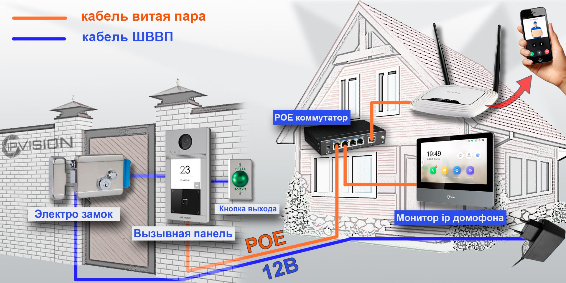
Если всё же ваш электрик сделал разводку витой пары по старой аналоговой схеме, соединив кабелем напрямую два сетевых устройства, не отчаевайтесь, сделать ip домофонию есть возможность и при такой разводке.
2. Настройка ip домофона Hikvision
|
В программе SADP активируем вызывную панель и монитор домофонной системы. После активации присваиваем каждому устройству ip адрес и шлюз (Gateway). Если не хотите устанавливать утилиту SADP, то можете активировать устройство Hikvision через web интерфейс на браузере. При этом ip адрес обычно по умолчанию будет 192.168.1.64 (поменять обязательно на другой, что бы не было конфликта ip адресов с монитором домофона) Так, введя этот ip адрес в браузер у вас откроется диалоговое окно, где вы и сможете активировать устройство, а именно, нужно будет придумать свой персональный пароль, логин будет admin. Частая проблема это раскладка клавиатуры RU/EN !!! Проверьте внимательно, что бы бы ввод пароля был на английском Как уже говорил, у ip вызывных панелей Hikvision есть свой web интерфейс, нужное зайти на него через любой браузер, и произвести настройку. На видео ниже 2 способа настройки ip домофона Hikvision: 1. Локально через монитор 2. Через браузер Вместе с тем, у мониторов ip домофона Hikvision нет своего web интерфейса, а вы хотите произвести настройку или управлять монитором с компа, то настройку устройств можно производить на компьютере в программе IVMS-4200. Добавляем наши ip домофоны в клиент IVMS — 4200 логин и пароль — тот что задали при активации Если в вашей системе ip домофонии будет более 2х устройств, например многоабонентская система, то для корректной работы советую всё же прошить каждое устройство последней прошивкой. Здесь найдете ссылки на последнюю прошивку для ip домофонов Hikvision (ссылки на версии прошивок). После прошивки устройств Hikvision, что бы избежать остаточных багов, обязательно сбросте устройство до заводских настроек, кстати это правило касается не только ip домофонии. |
3. Настройка монитора ip домофона Hikvision в программе IVMS — 4200Видео подключение и настройки ip домофона Hikvision в программе IVMS-4200 Для настройки монитора ip домофона Hikvision в бесплатной программе IVMS — 4200 нужно добавить устройство в эту программу. Здесь же можно и произвести первичную активацию устройства, если вы не активировали вашу вызывную и монитор ранее в удобной и простой утилите SADP. 1. При выборе online device в нижнем поле отобразяться все ваши устройства в сети. Выбираем монитор и жмем добавить «Add».
2. В открывшемся диалоговом окне указываем любое имя устройству, ставим галочку синхронизировать время, указываем логин и пароль, тот который вы задали при активации. 3. Нажимаем шестеренку и попадаем в меню настроек. Основная логика заключается в том, что бы на мониторе ip домофона в меню настроек конфигурация связанной сети указать ip адрес вашей вызывной панели в строку Main Door Station ip adress.
4. Всё, ip домофония связана и готова к работе, проверьте, нажав на кнопку вызова, должен пойти вызов на моиторе домофона. |
4. Выпуск карт ip домофона Hikvision
|
ip домофоны Hikvision поддерживают стандарт карт Mifare. Для выпуска карт необходимо сначала прислонить к считывателю мастер карту (в комплекте поставки). Затем программируем нужное количество карт для абонентов просто поочередно прикладывая карты к считывателю, завершаем выпуск карт повторно прислонив мастер карту к считывателю. Так же можно начать выпуск карт из меню web интерфейса самой вызывной панели. Такой способ удобен, если вы потеряли мастер карту от вызывной панели. |
|
|
5. Подключение электро замка к ip домофону Hikvision
|
Для подключения к ip домофону Hikvision электро-механического замка необходимо плюс питания соединить с электро -механическим замком и синим кабелем вызывной панели, а минус соединить с зеленым кабелем вызывной панели . |
|
|
|
|
6. Подключение ip камеры
|
Для подключения к ip домофону Hikvision цифровой камеры необходимо в мониторе видеодомофона зайти в настройки, далее -конфигурация, пароль администратора (пароль которй вы задали при активации монитора) . Затем — Устройство — добавить устройство — выбрать тип устройства — ip камера, затем в открывшемся окне присвойте любое имя для камеры, введите ip адрес камеры видеонаблюдения, а так же логин и пароль от камеры, жмем сохранить. Важно! Вторичный поток в ip камере должен быть выставлен кодеком H.264 |
|
|
7. Добавление подчинённого монитора к основному монитору ip домофона
|
|
| Для подключения второго, подчиненного монитора к основному монитору ip домофона Hikvision, нужно зайти в настройки добавочного монитора видеодомофона, далее — интерком, конфигурация идентификатора — тип устройства: Добавочный номер станции, ниже в строке указываем номер 1 — сохранить — перезагрузка устройства. После перезагрузки монитор стал добавочным. |
|
|
Затем повторно заходим на дополнительный монитор и в разделе сеть выбираем конфигурация связанной сети в строке ip адрес основной станции в помещении прописываем ip адрес главного монитора (не вызывной панели), в нашем случае это 192.168.0.110, жмем сохранить. |
|
|
8. Настройка многоабонентской системы ip домофонии Hikvision
Логика настройки многоабонентской ip домофонии Hikvision
Для всех мониторов:
1. указать №№ квартир (101, 102, 103 и т.д.)
2. указать ip адрес (главного) домофона (нашей многоабонетской ip вызывной панели)
Для главной многоабонетской ip вызывной панели:
1. Присвоить каждой кнопке № квартиры (101, 102, 103 и т.д.). Всё, настройка выполнена
Если же в системе есть подчиненные/межкомнатные вызывные панели ip домофонов hikvision, то
1. их необходимо перевести в режим не главной вызывной панели (Sub Villa Door Station), а после указать подчиненным панелям кто главная вызывная вызывная (прописать ip адрес Main Villa Door Station)
2. указать № квартиры (монитора — 101 или 102 или 103 и т.д.)
Ниже на видео пошагово как это сделать
9. Как настроить Модульную систему ip домофонии Hikvision на 6 абонентов
10. Установка ip домофона Hikvision
|
В комплекте поставки к ip домофонам Hikvision в металлическом корпусе типа DS-KV8102-IM содержится врезная пластиковая монтажная коробка, в комплекте с моделями в пластиковом корпусе DS-KV8102-IP металлическая пластина под контур панели, инструкция по монтажу. |
|
|
11. Подключение ip домофона Hikvision к интернету
|
Подключить к интернету для принятия вызова на мобильный телефон до недавнего времени можно было только монитор ip видеодомофона. Если хотите добавить только вызывную панель листайте дальше. Для подключения к интернету ip домофона Hikvision необходимо установить на смартфон мобильное приложение Hik-Connect. Скачать Hik-connect для android и ios. Добавить устройство в мобильном приложении можно сканировав QR-код, расположенный на задней панели или ввести серийный номер монитора. Подробную процедуру добавления ip домофона к облачному сервису смотрите на видео ниже. |
|
|
|
|
| Вместе с тем, можно добавить к интернету и вызывную панель без монитора, но для этого нужно перепрошить специальной sip прошивкой | |
|
|
|
| Прошивка для автономной работы IP вызывной панели Hikvision DS-KB8112-IM здесь | Прошивка для автономной работы IP вызывной панели Hikvision DS-KV6113-WPE1 здесь |
12. Как прошить ip домофон Hikvision
Скачать прошивки для ip видеодомофонов Hikvision
13. Подключение тревожных датчиков к ip домофону Hikvision
|
Подключить к монитору ip домофона Hikvision можно до 8-и разных датчиков. Датчики могут быть как проводные, так и беспроводные. Например у известной компании AJAX есть плата сопряжения Oc Bridge, с помощью которой можно добавить беспроводные тревожные датчики AJAX к монитору ip домофона Hikvision |
|
|
|
|
14. Важные моменты при выборе ip вызывной панели Hikvision.
Плюсы и минусы моделей в обзоре на готовые комплекты ip видеодомофона.
1. Обращаю внимание, что не все модели имеют считыватель карт, однако к ним можно подключить и внешний считыватель карт.
2. Так же важно сколько дверей можно подключить к одной вызывной панели, так например, если вызываня панель содержит два реле, то можно удаленно открывать не только калитку, но еще и например откатные ворота.
3. Вместе с тем, не все модели антивандальные, и при установке пластиковых вызывных панелей на улице, советуем использовать защитные козырьки от попадания атмосферных осадков. Так же некоторые вызывные панели содержат модуль Wi — Fi, слот для карты памяти. А вот питание на все устройства ip домофонии можно подать как по РОЕ, так и 12В.
4. Отдельно хотелось бы отметить тот факт, что только монитор ip домофона можно добавить к интернету, однако есть одно исключние. Есть специальные прошивки, с помощью которых можно подключить также ip вызывную панель к облаку Hik-Connect, отдельно без монитора.
|
|
|
|
|
|
Смотреть все готовые комплекты ip видеодомофонов
|
15. Часто задаваемые вопросы: |
|
| 1. Какие кабеля и как их надо разводить в доме, что бы подключить систему ip домофонии? |
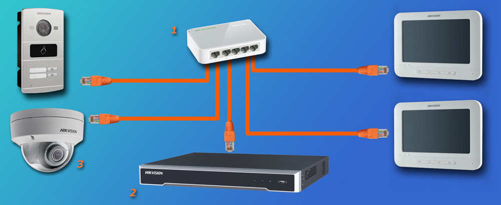
Нужен сетевой кабель витая пара (UTP). Подключаются оба устройства в вашу локальную сеть, например через коммутатор (Свич). Но можно и соединить монитор и вызывную панель напрямую кабелем, однако в таком случае очень сильно урежится функционал ip домофонии, а именно не сможете подключить устройство к интернету. |
|
1. Свич; 2. Сетевой видеорегистратор (NVR); 3. ip камера |
|
| 2. Нужен ли отдельный кабель для подачи питания к каждому устройству ip домофонии, например ШВВП ? |
Не обязательно, можно использовать свободные жилы витой пары (UTP) для подачи питания. |
| 3. Какие кабеля нужно провести от вызывной панели к электро механическому замку или защелке в двери, что бы удаленно управлять открытием входной двери? |
Достаточно одного кабеля витая пара от вызывной панели к электромеханическому замку |
| 4. Какой использовать видеорегистратор для объединения системы видеонаблюдения и ip домофонии, что бы записывать видео поток с ip вызывной панели, а так же просматривать на мониторе домофонной системы все ip камеры в сети? | Необходимо использовать видеорегистратор без РОЕ, поскольку в регистраторе с технологией РОЕ — вытянуть видео поток не получится, поскольку такой регистратор использует для камер вторую, внутреннюю подсеть. |

Затем повторно заходим на дополнительный монитор и в разделе сеть выбираем конфигурация связанной сети в строке ip адрес основной станции в помещении прописываем ip адрес главного монитора (не вызывной панели), в нашем случае это 192.168.0.110, жмем сохранить.
8. Настройка многоабонентской системы ip домофонии Hikvision
Логика настройки многоабонентской ip домофонии Hikvision
Для всех мониторов:
1. указать №№ квартир (101, 102, 103 и т.д.)
2. указать ip адрес (главного) домофона (нашей многоабонетской ip вызывной панели)
Для главной многоабонетской ip вызывной панели:
1. Присвоить каждой кнопке № квартиры (101, 102, 103 и т.д.). Всё, настройка выполнена
Если же в системе есть подчиненные/межкомнатные вызывные панели ip домофонов hikvision, то
1. их необходимо перевести в режим не главной вызывной панели (Sub Villa Door Station), а после указать подчиненным панелям кто главная вызывная вызывная (прописать ip адрес Main Villa Door Station)
2. указать № квартиры (монитора — 101 или 102 или 103 и т.д.)
Ниже на видео пошагово как это сделать
9. Как настроить Модульную систему ip домофонии Hikvision на 6 абонентов
10. Установка ip домофона Hikvision
|
В комплекте поставки к ip домофонам Hikvision в металлическом корпусе типа DS-KV8102-IM содержится врезная пластиковая монтажная коробка, в комплекте с моделями в пластиковом корпусе DS-KV8102-IP металлическая пластина под контур панели, инструкция по монтажу. |
|
|
11. Подключение ip домофона Hikvision к интернету
|
Подключить к интернету для принятия вызова на мобильный телефон до недавнего времени можно было только монитор ip видеодомофона. Если хотите добавить только вызывную панель листайте дальше. Для подключения к интернету ip домофона Hikvision необходимо установить на смартфон мобильное приложение Hik-Connect. Скачать Hik-connect для android и ios. Добавить устройство в мобильном приложении можно сканировав QR-код, расположенный на задней панели или ввести серийный номер монитора. Подробную процедуру добавления ip домофона к облачному сервису смотрите на видео ниже. |
|
|
|
|
| Вместе с тем, можно добавить к интернету и вызывную панель без монитора, но для этого нужно перепрошить специальной sip прошивкой | |
|
|
|
| Прошивка для автономной работы IP вызывной панели Hikvision DS-KB8112-IM здесь | Прошивка для автономной работы IP вызывной панели Hikvision DS-KV6113-WPE1 здесь |
12. Как прошить ip домофон Hikvision
Скачать прошивки для ip видеодомофонов Hikvision
13. Подключение тревожных датчиков к ip домофону Hikvision
|
Подключить к монитору ip домофона Hikvision можно до 8-и разных датчиков. Датчики могут быть как проводные, так и беспроводные. Например у известной компании AJAX есть плата сопряжения Oc Bridge, с помощью которой можно добавить беспроводные тревожные датчики AJAX к монитору ip домофона Hikvision |
|
|
|
|
14. Важные моменты при выборе ip вызывной панели Hikvision.
Плюсы и минусы моделей в обзоре на готовые комплекты ip видеодомофона.
1. Обращаю внимание, что не все модели имеют считыватель карт, однако к ним можно подключить и внешний считыватель карт.
2. Так же важно сколько дверей можно подключить к одной вызывной панели, так например, если вызываня панель содержит два реле, то можно удаленно открывать не только калитку, но еще и например откатные ворота.
3. Вместе с тем, не все модели антивандальные, и при установке пластиковых вызывных панелей на улице, советуем использовать защитные козырьки от попадания атмосферных осадков. Так же некоторые вызывные панели содержат модуль Wi — Fi, слот для карты памяти. А вот питание на все устройства ip домофонии можно подать как по РОЕ, так и 12В.
4. Отдельно хотелось бы отметить тот факт, что только монитор ip домофона можно добавить к интернету, однако есть одно исключние. Есть специальные прошивки, с помощью которых можно подключить также ip вызывную панель к облаку Hik-Connect, отдельно без монитора.
|
|
|
|
|
|
Смотреть все готовые комплекты ip видеодомофонов
|
15. Часто задаваемые вопросы: |
|
| 1. Какие кабеля и как их надо разводить в доме, что бы подключить систему ip домофонии? |
Нужен сетевой кабель витая пара (UTP). Подключаются оба устройства в вашу локальную сеть, например через коммутатор (Свич). Но можно и соединить монитор и вызывную панель напрямую кабелем, однако в таком случае очень сильно урежится функционал ip домофонии, а именно не сможете подключить устройство к интернету. |
|
1. Свич; 2. Сетевой видеорегистратор (NVR); 3. ip камера |
|
| 2. Нужен ли отдельный кабель для подачи питания к каждому устройству ip домофонии, например ШВВП ? |
Не обязательно, можно использовать свободные жилы витой пары (UTP) для подачи питания. |
| 3. Какие кабеля нужно провести от вызывной панели к электро механическому замку или защелке в двери, что бы удаленно управлять открытием входной двери? |
Достаточно одного кабеля витая пара от вызывной панели к электромеханическому замку |
| 4. Какой использовать видеорегистратор для объединения системы видеонаблюдения и ip домофонии, что бы записывать видео поток с ip вызывной панели, а так же просматривать на мониторе домофонной системы все ip камеры в сети? | Необходимо использовать видеорегистратор без РОЕ, поскольку в регистраторе с технологией РОЕ — вытянуть видео поток не получится, поскольку такой регистратор использует для камер вторую, внутреннюю подсеть. |
© — защищено авторским правом, любое использование материала полностью либо в части, возможно только с согласия автора
Чтобы задать вопрос Авторизируйтесь с помощью одной из предложенных соц.сети