-
Contents
-
Table of Contents
-
Bookmarks
Quick Links
User Manual
Installation
Industrial Ethernet Workgroup Switch
MACH104 Full Gigabit Family
MACH104-20TX-F
FAULT
USB
V.24
FAULT
RM
Sb
P
MACH104-20TX-F…
MACH104-20TX-FR
FAULT
USB
V.24
FAULT
RM
Sb
P
MACH104-20TX-FR…
MACH104-20TX-F-4PoE
FAULT
USB
V.24
FAULT
RM
Sb
P
MACH104-20TX-F-4PoE…
Installation MACH104
Release 08 01/2019
5
7
1
3
2
4
6
8
5
7
1
3
2
4
6
8
P
5
7
1
3
2
4
6
8
9
11
13
15
10
12
14
16
9
11
13
15
10
12
14
16
9
11
13
15
10
12
14
16
https://hirschmann-support.belden.com
17
19
21
23
18
20
22
24
17
19
21
23
18
20
22
24
17
19
21
23
18
20
22
24
Technical support
Summary of Contents for Hirschmann MACH104-20TX-FR Series
- Home
- Brands
- Hirschmann Manuals
- Network Router
- MACH104-20TX-FR
|
|
Related Devices:
|
Types of Manuals:
The main types of Hirschmann MACH104-20TX-FR instructions:
- User guide — rules of useing and characteristics
- Service manual — repair, diagnostics, maintenance
- Operation manual — description of the main functions of equipment
Network Router, Switch User Guides by Hirschmann:
Similar to Hirschmann MACH104-20TX-FR Manuals, User Guides and Instructions:
-
Belkin F5U261
EnEsItNePoP74102em F5U261FrDeHi-Speed USB 2.04-Port Drive Bay Hub User ManualManuel d’utilisation du hub 4 ports en baieBenutzerhandbuch für Hub mit 4 Anschlüssen fürUSB 2.0 Hi-Speed zum Einbau in LaufwerkschachtGebruikershandleiding Hi-Speed USB 2.0schijfpositiehub met 4 poorten Manual del usuario del Concentrado …
F5U261 Switch, 72
-
ShoreTel ShoreGear 90BRI
IntroductionAbout the ShoreGear 90BRIThe SG-90BRI Voice Switch connects enterprise telephone extensions through an internal IP network, or to any central office (CO) ISDN BRI trunk line. The switch provides connectivity through:• Two RJ-45 local area network (LAN) connectors• Four RJ-45 ISDN BRI ports for connect …
ShoreGear 90BRI Switch, 2
-
Philio Technology Corporation PAN32
In Wall Micro switch (Dry Contact) PAN32 Introduction This product can operate in any Z-Wave network with other Z-Wave certified devices from other manufacturers. All mains operated nodes within the network will act as repeaters regardless of vendor to increase reliability of the network. Mini size desig …
PAN32 Switch, 7
-
anko 42953272
User Manual USB-C to HDMI adaptor Keycode 42953272 Please read all the information carefully before you use the device to avoid accidents and keep it for future reference. Product Introduction 1. This product is a multi-functional extension of type-c HUB, compatible with USB3.1 USB-C interface for mobile phon …
42953272 Switch, 3
User Manual
Installation
Industrial Ethernet Workgroup Switch
MACH104-PoEP Full Gigabit Family
FAULT
RM
Sb
x y
MACH104
USB V.24
FAULT
1 3
P
2 4
MACH104-16TX-PoEP+2X…
MACH104-16TX-PoEP+2X-R…
MACH104-16TX-PoEP+2X-E…
FAULT
RM
Sb
x y
MACH104
USB V.24
FAULT
1 3
P
2 4
MACH104-16TX-PoEP…
MACH104-16TX-PoEP-R…
MACH104-16TX-PoEP-E…
5 7 9 11
6 8 10 12
5 7 9 11
6 8 10 12
13 15 17 19
14 16 18 20
13 15 17 19
14 16 18 20
21 22
Installation MACH104-PoEP
Release 06 11/2013
Technical support https://hirschmann-support.belden.eu.com
The naming of copyrighted trademarks in this manual, even when not specially indicated, should not be taken to mean that these names may be considered as free in the sense of the trademark and tradename protection law and hence that they may be freely used by anyone.
© 2013 Hirschmann Automation and Control GmbH
Manuals and software are protected by copyright. All rights reserved. The copying, reproduction, translation, conversion into any electronic medium or machine scannable form is not permitted, either in whole or in part. An exception is the preparation of a backup copy of the software for your own use. For devices with embedded software, the end-user license agreement on the enclosed CD/DVD applies.
The performance features described here are binding only if they have been expressly agreed when the contract was made. This document was produced by Hirschmann Automation and
Control GmbH according to the best of the company’s knowledge. Hirschmann reserves the right to change the contents of this document without prior notice. Hirschmann can give no guarantee in respect of the correctness or accuracy of the information in this document.
Hirschmann can accept no responsibility for damages, resulting from the use of the network components or the associated operating software. In addition, we refer to the conditions of use specified in the license contract.
You can get the latest version of this manual on the Internet at the Hirschmann product site
(www.hirschmann.com).
Printed in Germany
Hirschmann Automation and Control GmbH
Stuttgarter Str. 45-51
72654 Neckartenzlingen
Germany
Tel.: +49 1805 141538
Installation 039 782-001-06-1113 –
21.11.2013
Contents
Safety instructions
About this manual
Legend
1 Description
1.1
General device description
1.2
Device name and product code
1.3
Device variants available
1.4
Device views
1.4.1 Front view
1.4.2 Rear view
1.5
Supply voltage
1.5.1 MACH104-16TX-PoEP…
MACH104-16TX-PoEP+2X…
1.5.2 MACH104-16TX-PoEP-R…
MACH104-16TX-PoEP+2X-R…
1.5.3 MACH104-16TX-PoEP-E…
MACH104-16TX-PoEP+2X-E…
1.6
Ethernet ports
1.6.1 10/100/1000 Mbit/s twisted pair port
1.6.2 100 Mbit/s F/O port
1.6.3 1000 Mbit/s F/O port
1.6.4 10-Gbit/s F/O port
1.6.5 PoE ports
1.6.6 Combo ports
1.6.7 SFP/XFP transceiver
1.7
Display elements
1.7.1 Device state
1.7.2 Port state
1.8
Management interfaces
1.8.1 V.24 interface (external management)
1.8.2 USB interface
1.9
Signal contact
Installation MACH104-PoEP
Release 06 11/2013
5
10
10
15
15
15
17
17
18
18
15
15
16
16
19
19
20
21
21
22
22
11
11
12
12
13
13
14
14
3
2 Installation
2.1
Unpacking and checking the content of the package
2.2
Installing SFP/XFP transceivers (optional)
2.3
MACH104-16TX-PoEP-E…,
MACH104-16TX-PoEP+2X-E…:
Wiring and assembling the operating voltage
2.4
Wiring and assembling the signal contact
2.5
Installing the device and grounding
2.5.1 Selecting the assembly location
2.5.2 Mounting on a flat surface
2.5.3 Mounting in a switch cabinet
2.5.4 Mounting on the wall
2.5.5 Grounding the device
2.6
Operating the device
2.7
Connecting network cables
3 Basic set-up
3.1
Default settings
4 Maintenance and service
5 Deinstallation
5.1
Removing the device
5.2
Deinstalling the SFP/XFP transceivers
6 Technical data
A Further Support
34
34
34
35
24
25
26
26
27
27
28
29
29
30
31
31
33
44
23
23
24
4
Installation MACH104-PoEP
Release 06 11/2013
Safety instructions
Certified usage
Only use the device for application cases that are described in the
Hirschmann product information, including this manual. Only operate the device according to the technical specifications.
Supply voltage
The supply voltage is electrically isolated from the housing.
Solely connect a supply voltage that corresponds to the type plate of your device.
This applies to the following device variants only:
MACH104-16TX-PoEP-E…
MACH104-16TX-PoEP+2X-E…
Install an input fuse with a maximum rating of 10 A, characteristic B, into the supply line to the voltage input.
Use conductors with a minimum cross-section of 1 mm
2
for the supply line to the voltage input.
Exclusively connect SELV circuits with the voltage restrictions in accordance with IEC/EN 60950-1 to the supply voltage connections.
Ensure that the connected supply voltage complies with the requirements according to IEEE 802.3af or IEEE 802.3at.
Use undamaged parts.
The device does not contain any service components. Internal fuses are only triggered if there is a fault in the device. If the device is not functioning correctly, or if it is damaged, switch off the voltage supply and return the device to the plant for inspection.
Only switch on the device when the housing is closed.
Only use connection cables that are permitted for the specified temperature range.
Relevant for North America:
Only use copper wire/conductors of class 1, 60/75°C or 75°C.
Make sure that the disconnecting device is easily accessible so that the MACH104-PoEP device can be disconnected from the mains voltage.
If you disconnect the device from the mains voltage using
— the plug in the socket
— an on/off switch it must be easily accessible.
This applies to the following device variants only:
MACH104-16TX-PoEP-R…
MACH104-16TX-PoEP+2X-R…
Pull both non-heating plugs to disconnect the device from mains voltage.
Installation MACH104-PoEP
Release 06 11/2013
5
Shielding ground
The shielding ground of the connectable twisted pair lines is connected to the protective conductor connection via the front panel.
Beware of possible short circuits when connecting a cable section with conductive shielding braiding.
Housing
Only technicians authorized by the manufacturer are permitted to open the housing.
The device is grounded via the voltage supply socket.
Never insert sharp objects (small screwdrivers, wires, etc.) into the inside of the device.
Verify that the electrical installation meets locally or nationally applicable safety regulations.
Keep the ventilation slits free to ensure good air circulation.
Make sure there is at least 3.94 inches (10 cm) of space in front of the ventilation slits of the housing.
The device must be installed in the horizontal or upright position, either as a table unit in the switch cabinet
(see figure 6)
or on the wall (see
figure 7)
.
In order to fix the device to a concrete wall choose screws with a thread major diameter of at least 5 mm.
Environment
Only operate the device at the specified ambient temperature
(temperature of the surrounding air at a distance of up to 5 cm from the device) and at the specified relative humidity.
When you are selecting the installation location, make sure you observe the climatic threshold values specified in the technical data.
Use the device in an environment with a maximum pollution degree that complies with the specifications in the technical data.
Qualification requirements for personnel
Qualified personnel as understood in this manual and the warning signs, are persons who are familiar with the setup, assembly, startup, and operation of this product and are appropriately qualified for their job. This includes, for example, those persons who have been:
trained or directed or authorized to switch on and off, to ground and to label power circuits and devices or systems in accordance with current safety engineering standards;
trained or directed in the care and use of appropriate safety equipment in accordance with the current standards of safety engineering;
trained in providing first aid.
6
Installation MACH104-PoEP
Release 06 11/2013
General safety instructions
This device is operated by electricity. You must follow precisely the prescribed safety requirements for the voltage connections in this document.
See “Supply voltage” on page 5.
Non-observance of these safety instructions can cause material damage and/or injuries.
Only appropriately qualified personnel should work on this device or in its vicinity. The personnel must be thoroughly familiar with all the warnings and maintenance procedures outlined in this operating manual.
The proper and safe operation of this device depends on proper handling during transportation, proper storage and assembly, and conscientious operation and maintenance procedures.
Never start operation with damaged components.
Only use the devices in accordance with this manual. In particular, observe all warnings and safety-related information.
Any work that may be required on the electrical installation may only be carried out by personnel trained for this purpose.
Two or more devices configured with the same IP address can cause unpredictable operation of your network.
Install and maintain a process that assigns a unique IP address to every device in the network.
Please note that products recommended as accessories may have characteristics that do not fully correspond to those of the corresponding product. This may limit their possible usage in the overall system.
Only connect the PoE connections to PoE-supplier devices whose data connections are located in the interior of the building and are specified as SELV circuits.
Note: LED or LASER components in compliance with IEC 60825-1
(2007):
CLASS 1 LASER PRODUCT
CLASS 1 LED PRODUCT
National and international safety regulations
Make sure that the electrical installation meets local or nationally applicable safety regulations.
CE marking
The labeled devices comply with the regulations contained in the following
European directive(s):
Installation MACH104-PoEP
Release 06 11/2013
7
Device variant
MACH104-16TX-PoEP…
MACH104-16TX-PoEP+2X…
MACH104-16TX-PoEP-R…
MACH104-16TX-PoEP+2X-R…
MACH104-16TX-PoEP-E…
MACH104-16TX-PoEP+2X-E…
MACH104-16TX-PoEP…
MACH104-16TX-PoEP+2X…
MACH104-16TX-PoEP-R…
MACH104-16TX-PoEP+2X-R…
Directive
2011/65/EU (RoHS)
Directive of the European Parliament and of the Council on the restriction of the use of certain hazardous substances in electrical and electronic equipment.
2004/108/EC (EMC)
Directive of the European Parliament and the council for standardizing the regulations of member states with regard to electromagnetic compatibility.
2006/95/EC
Directive of the European Parliament and the council for standardizing the regulations of member states with regard to electrical equipment to be used within specific voltage ranges.
In accordance with the above-named EU directive(s), the EU conformity declaration will be at the disposal of the relevant authorities at the following address:
Hirschmann Automation and Control GmbH
Stuttgarter Str. 45-51
72654 Neckartenzlingen
Germany
Tel.: +49 1805 141538
The product can be used in the industrial sector.
Interference immunity: EN 61000-6-2
Emitted interference: EN 55022
Reliability: EN 60950-1
Warning! This is a class A device. This device can cause interference in living areas, and in this case the operator may be required to take appropriate measures.
Note: The assembly guidelines provided in these instructions must be strictly adhered to in order to observe the EMC threshold values.
FCC note
This device complies with part 15 of the FCC rules. Operation is subject to the following two conditions: (1) this device may not cause harmful interference; (2) this device must accept any interference received, including interference that may cause undesired operation.
8
Installation MACH104-PoEP
Release 06 11/2013
Appropriate testing has established that this device fulfills the requirements of a class A digital device in line with part 15 of the FCC regulations.
These requirements are designed to provide sufficient protection against interference when the device is being used in a business environment.
The device creates and uses high frequencies and can also radiate high frequencies, and if it is not installed and used in accordance with this operating manual, it can cause radio transmission interference. The use of this device in a living area can also cause interference, and in this case the user is obliged to cover the costs of removing the interference.
Recycling note
After usage, this device must be disposed of properly as electronic waste, in accordance with the current disposal regulations of your county, state, and country.
Installation MACH104-PoEP
Release 06 11/2013
9
About this manual
The “Installation” user manual contains a device description, safety instructions, a description of the display, and the other information that you need to install the device.
The following manuals are available as PDF files on the CD/DVD supplied:
Installation user manual
Basic Configuration user manual
Redundancy Configuration user manual
Reference manual for the graphical user interface
Command Line Interface user manual
The Industrial HiVision Network Management Software provides you with additional options for smooth configuration and monitoring:
ActiveX control for SCADA integration
Auto-topology discovery
Browser interface
Client/server structure
Event handling
Event log
Simultaneous configuration of multiple devices
Graphical user interface with network layout
SNMP/OPC gateway.
Legend
The symbols used in this manual have the following meanings:
Listing
Work step
Subheading
10
Installation MACH104-PoEP
Release 06 11/2013
1 Description
1.1
General device description
The MACH104-PoEP family provides you with a range of device variants.
The MACH104-PoEP devices are designed for the special requirements of industrial automation. They meet the relevant industry standards, provide very high operational reliability, even under extreme conditions, and also long-term reliability and flexibility.
The devices with software variant L2… allow you to set up switched industrial
Ethernet networks that conform to the IEEE 802.3 standard.
The devices with software variant L2… allow you to set up switched and routed industrial Ethernet networks that conform to the IEEE 802.3 standard.
The devices work without a fan.
The following installation options are available:
19″ switch cabinet
Installing the device on a flat surface
Mounting on a flat surface
You have the option of choosing various media to connect to the terminal devices and other network components:
twisted pair cable
multimode F/O
singlemode F/O
The ring redundancy concept allows the network to be reconfigured quickly after a failure.
There are convenient options for managing the device. Administer your devices via:
a Web browser
Telnet
management software (such as Industrial HiVision)
a V.24 interface (locally on the device)
The devices provide you with a large range of functions, which the manuals for the operating software inform you about. You will find these manuals as
PDF files on the enclosed CD/DVD, or you can download them from the
Internet on the Hirschmann product pages ( www.hirschmann.com
).
The Hirschmann network components help you ensure continuous communication across all levels of the company.
Installation MACH104-PoEP
Release 06 11/2013
11
1.2
Device name and product code
The device name corresponds to the product code. The product code is made up of characteristics with defined positions. The characteristic values stand for specific product properties.
Item
1 … 17
18 + x
Last 4 positions
Product characteristic
Basic properties of all device variants
Characteristi c value
MACH104-
16TX-PoEP
Special properties of the device variants
Blank
-R
-E
+2X
+2X-R
+2X-E
Software variant -L2P
-L3P
Description
Industrial Ethernet Workgroup Switch with:
4 × 1000-Mbit/s Combo Ports
16 × 1000-Mbit/s Twisted-Pair Ports with
PoE+
Rated voltage range AC
100 V … 240 V, 50 Hz … 60 Hz
Rated voltage range AC
100 V … 240 V, 50 Hz … 60 Hz
Redundant power supply
For the use of type-1-powered devices (PoE):
Nominal voltage DC
48 V
For the use of type-2-powered devices (PoE+):
Nominal voltage DC
54 V
Additionally: 2 × 10-Gbit/s F/O ports
Rated voltage range AC
100 V … 240 V, 50 Hz … 60 Hz
Additionally: 2 × 10-Gbit/s F/O ports
Rated voltage range AC
100 V … 240 V, 50 Hz … 60 Hz
Redundant power supply
Additionally: 2 × 10-Gbit/s F/O ports
For the use of type-1-powered devices (PoE):
Nominal voltage DC
48 V
For the use of type-2-powered devices (PoE+):
Nominal voltage DC
54 V
Layer 2 Professional
Layer 3 Professional
Table 1: Device name and product code
1.3
Device variants available
Under “Order numbers” on page 40
you can see which device variants are available.
12
Installation MACH104-PoEP
Release 06 11/2013
1.4
Device views
1.4.1
Front view
FAULT
RM
Sb
x y
MACH104
USB V.24
FAULT
P
1 3
5 7 9 11 13 15 17 19
6 8 10 12 14 16 18 20
2 4
1 2 3 4 5 6 7
1
2
3
4
5
LED display elements
Signal contact
USB interface
V.24 interface
Ports 1 to 4
Device Status
6
7
Ports 5 to 12
Ports 13 to 20
1000-Mbit/s Combo Ports
1000-Mbit/s Twisted-Pair Ports with PoE+
1000-Mbit/s Twisted-Pair Ports with PoE+
8
9
Ports 21, 22 10-Gbit/s F/O ports
MAC address of device (label)
10 Bracket
Table 2: Front view of device variants:
MACH104-16TX-PoEP+2X…
MACH104-16TX-PoEP+2X-R…
MACH104-16TX-PoEP+2X-E…
21
8
22
1
4
5
2
3
6
7
8
9
FAULT
RM
Sb
x y
MACH104
USB V.24
FAULT
P
1 3
5 7 9 11 13 15 17 19
6 8 10 12 14 16 18 20
2 4
1 2 3 4
LED display elements
5
Device Status
6 7
Signal contact
USB interface
V.24 interface
Ports 1 to 4
Ports 5 to 12
Ports 13 to 20
1000-Mbit/s Combo Ports
1000-Mbit/s Twisted-Pair Ports with PoE+
1000-Mbit/s Twisted-Pair Ports with PoE+
MAC address of device (label)
Bracket
Table 3: Front view of device variants:
MACH104-16TX-PoEP…
MACH104-16TX-PoEP-R…
MACH104-16TX-PoEP-E…
9 10
8 9
Installation MACH104-PoEP
Release 06 11/2013
13
1.4.2
Rear view
1
1 Non-heating appliance socket
Connecting the supply voltage
Table 4: Rear view of device variants:
MACH104-16TX-PoEP…
MACH104-16TX-PoEP+2X…
1
1
2
Non-heating appliance socket
Non-heating appliance socket
Connecting the supply voltage
Supply voltage 2
Connecting the supply voltage
Supply voltage 1
Table 5: Rear view of device variants:
MACH104-16TX-PoEP-R…
MACH104-16TX-PoEP+2X-R…
1
2
1 3-pin DC socket Connecting the supply voltage
Table 6: Rear view of device variants:
MACH104-16TX-PoEP-E…
MACH104-16TX-PoEP+2X-E…
1.5
Supply voltage
Note: Read the safety guidelines under
“Supply voltage” on page 5
.
Note: Observe the information about the voltages to be connected:
“Technical data” on page 35
14
Installation MACH104-PoEP
Release 06 11/2013
1.5.1
MACH104-16TX-PoEP…
MACH104-16TX-PoEP+2X…
For the supply voltage, the following applies:
A power module providing the PoE voltage and the internal supply voltage is integrated in the device.
Supply voltage is connected via a non-heating appliance socket.
The input voltage is electrically isolated from the housing.
1.5.2
MACH104-16TX-PoEP-R…
MACH104-16TX-PoEP+2X-R…
For the supply voltage, the following applies:
The supply voltage can be connected redundantly.
Two power modules providing the PoE voltage and the internal supply voltage are integrated in the device. The power modules operate in loadsharing mode.
Supply voltage is connected via non-heating appliance sockets.
The input voltage is electrically isolated from the housing.
Both inputs are separate from one another.
Note: With non-redundant supply of the mains voltage, the device reports a power failure. You can prevent this message by applying the supply voltage via both inputs, or by changing the configuration in the Management.
1.5.3
MACH104-16TX-PoEP-E…
MACH104-16TX-PoEP+2X-E…
For the supply voltage, the following applies:
PoE voltage and internal supply voltage are provided by an external power module.
The voltage supply is connected via a 3-pin terminal block with snap locks.
You will find further information under “MACH104-16TX-PoEP-E…,
MACH104-16TX-PoEP+2X-E…: Wiring and assembling the operating voltage” on page 24 .
1.6
Ethernet ports
You can connect terminal devices and other segments on the ports of the device via twisted pair cables or F/O cables.
1.6.1
10/100/1000 Mbit/s twisted pair port
This port is an RJ45 socket.
Installation MACH104-PoEP
Release 06 11/2013
15
The 10/100/1000 Mbit/s twisted pair port offers you the ability to connect network components according to the IEEE 802.3 10BASE-T/100BASE-
TX/1000BASE-T standard.
This port supports:
Autonegotiation
Autopolarity
Autocrossing (if autonegotiation is activated)
1000 Mbit/s full duplex
100 Mbit/s half-duplex mode, 100 Mbit/s full duplex mode
10 Mbit/s half-duplex mode, 10 Mbit/s full duplex mode
Note: Some of these ports also support Power over Ethernet (PoE).
See “PoE ports” on page 17.
Delivery state: autonegotiation activated
The socket housing is electrically connected with the front panel.
The pin assignment corresponds to MDI-X.
Figure Pin
3
4
5
1
2
6
7
8
7
8
5
6
3
4
1
2
Function Ports with PoE support:
PoE voltage feed
BI_DB+ Minus terminal of the supply voltage
BI_DB− Minus terminal of the supply voltage
BI_DA+ Plus terminal of the supply voltage
BI_DD+
BI_DD−
BI_DA− Plus terminal of the supply voltage
BI_DC+
BI_DC−
Table 7: Pin assignment of a 1000 MBit/s TP interface in MDI-X mode, RJ45 socket — for PoE with the power supplied via the wire pairs transmitting the signal
1.6.2
100 Mbit/s F/O port
This port is an SFP slot.
100 MBit/s F/O ports enable the connection of terminal devices or independent network segments in compliance with the IEEE 802.3
100BASE-FX standard.
These ports support:
Full or half duplex mode
Default setting: Full duplex
1.6.3
1000 Mbit/s F/O port
This port is an SFP slot.
16
Installation MACH104-PoEP
Release 06 11/2013
1000 Mbit/s F/O ports enable the connection of terminal devices or independent network segments according to the IEEE 802.3 1000BASE-
SX/1000BASE-LX standard.
These ports support:
Autonegotiation
Full duplex mode
Delivery state: autonegotiation activated
1.6.4
10-Gbit/s F/O port
This port is an XFP slot.
The 10 Gbit/s F/O port allows you to connect network components according to the IEEE 802.3ae 10GBASE-SR/LR standard.
Full duplex mode
Default setting: Full duplex
1.6.5
PoE ports
Note: Only connect the PoE connections to PoE-supplier devices whose data connections are located in the interior of the building and are specified as SELV circuits.
Note: You will find further information under “10/100/1000 Mbit/s twisted pair port” on page 15 .
Some twisted-pair ports support Power over Ethernet (PoE):
Ports
1 to 4
5 to 20
PoE support
No
Yes
Table 8: Twisted-pair ports and PoE support
The PoE ports allow the connection and remote supply of, for example, IP telephones (Voice over IP), webcams, sensors, printer servers and WLAN access points. With PoE, power is supplied to these terminal devices via the twisted-pair cable.
The PoE support complies with the following standards:
Standard Description
IEEE 802.3af
Brief description
Classes
IEEE 802.3at
Brief description
Classes
Table 9: PoE support: Standards
PoE
Max. Powered Device (PD) class 0 (15.4 W)
PoE Plus
Max. Powered Device (PD) class 4 (30 W)
Installation MACH104-PoEP
Release 06 11/2013
17
The following applies to PoE ports:
The PoE voltage is supplied via the wire pairs transmitting the signal
(phantom voltage).
The individual ports (joint PoE voltage) are not electrically insulated from each other.
Maximum power available to PoE terminal devices:
240 W
Note: We recommend to distribute the PoE power equally between the two port groups (ports 5 to 12 and ports 13 to 20).
1.6.6
Combo ports
You have the option to alternatively connect F/O (via SFP transceivers) or twisted pairs to a combo port.
Media type
Twisted pair
Fiber optic cable
Connection options
Standard
Connection type either or
ISO/IEC 8802-03 10BASE-T/100BASE-
TX/1000BASE-T
RJ45
Standard
Connection type
IEEE 802.3 100BASE-
FX
Fast Ethernet SFP transceiver
Standard
Connection type
ISO/IEC 8802-03
1000BASE-SX/LX
1 Gigabit Ethernet SFP transceiver
Table 10: Combo ports: Connection options
When you are using an SFP transceiver, you get an optical interface. You thus deactivate the corresponding TP interface.
1.6.7
SFP/XFP transceiver
1
2
Figure 1: SFP transceiver and XFP transceiver
1 – Fast Ethernet F/O SFP transceiver
2 – Gigabit Ethernet F/O SFP transceiver
3 – 10-Gigabit Ethernet F/O XFP transceiver
3
18
Installation MACH104-PoEP
Release 06 11/2013
SFP is the acronym for Small Form-factor Pluggable which is also commonly known as mini-GBIC (GigaBit Interface Converter).
Both Fast Ethernet SFP transceivers and Gigabit Ethernet SFP transceivers are available for your device.
XFP transceivers are slightly larger than SFP transceivers. They support 10-
Gigabit Ethernet only.
Note: Only use Hirschmann SFP/XFP transceivers.
1.7
Display elements
After the operating voltage is set up, the software starts and initializes itself.
Afterwards, the device performs a self-test. During this process, various
LEDs light up.
The process takes around 15 seconds.
1.7.1
Device state
FAULT
RM
Sb
P
These LEDs provide information about conditions which affect the operation of the whole device.
The following table applies to the stated device variants only:
MACH104-16TX-PoEP-R…
MACH104-16TX-PoEP+2X-R…
LED Display
P Power supply
Color
Green
Yellow
Activity
Lights up
Lights up
None
Meaning
The supply voltages 1 and 2 are on.
The supply voltages 1 or 2 are on.
The supply voltages 1 and 2 are too low.
The following table applies to the stated device variants only:
MACH104-16TX-PoEP…
MACH104-16TX-PoEP-E…
MACH104-16TX-PoEP+2X…
MACH104-16TX-PoEP+2X-E…
LED Display
P Power supply
Color
Green
Activity
Lights up
None
Meaning
The supply voltage is on.
The supply voltage is too low.
Installation MACH104-PoEP
Release 06 11/2013
19
The following table applies to all device variants:
LED Display
Sb Stand-by
Color
Green
Activity
None
Lights up
Meaning
Stand-by mode not enabled
Standby mode enabled
FAULT Signal contact
RM
RM and
Sb
Ring
Manager
ACA memory operation
Red
Green
Yellow
None
Lights up
None
Lights up flashing
Lights up
The signal contact is closed — it is not reporting any detected errors.
The signal contact is open — it is reporting a detected error.
The RM function is deactivated.
The RM function is active.
The redundant port is disabled.
The device detects an incorrect configuration of the HIPER-Ring (e.g. the ring is not connected to the ring port).
The RM function is active.
The redundant port is enabled.
Error in the memory operation Flashing alternately flash synchronously
– 2 x per period flash synchronously
– 1 x per period
Save a configuration file from the ACA to the device.
Saving a configuration file from the device to the ACA.
If the manual adjustment is active on the “FAULT” signal contact, then the detected error display is independent of the setting of the signal contact.
1.7.2
Port state
These LEDs display port-related information.
The LEDs are directly located on the ports.
The following table applies to ports 5 to 20:
LED Display
left LED Link status right LED PoE
Color
Green
Activity
None
Meaning
The device detects an invalid or missing connection.
Lights up The device detects a valid connection.
Flashes 1 time a period The port is switched to stand-by.
Yellow
Flashes 3 times a period The port is disabled.
Flashing The device is sending and/or receiving data.
None orange Lights up
No PoE voltage at port.
No PoE voltage at port.
Flashes 1 time a period No PoE voltage at port because power capacity is exhausted.
Flashes 3 times a period The PoE voltage is deactivated in the management system.
20
Installation MACH104-PoEP
Release 06 11/2013
The following table applies to all other ports:
LED Display
left LED Link status right LED
(if present)
Color
Green
Yellow
Activity
None
Meaning
The device detects an invalid or missing connection.
Lights up The device detects a valid connection.
Flashes 1 time a period The port is switched to stand-by.
Flashes 3 times a period The port is disabled.
Flashing The device is sending and/or receiving data.
permanently active
1.8
Management interfaces
1.8.1
V.24 interface (external management)
The V.24 interface is an RJ11 socket.
The V.24 user interface is serial and allows you to connect the following devices directly:
External management station (VT100 terminal or PC with appropriate terminal emulation). With this management station, the Command Line
Interface (CLI) is available to you. Furthermore, the system monitor is available to you at the system start.
An AutoConfiguration Adapter ACA 11
VT 100 terminal settings
Speed
Data
Stopbit
Handshake
Parity
9,600 Baud
8 bit
1 bit off none
The socket housing is electrically connected to the front panel of the device.
The V.24 interface is not electrically isolated from the supply voltage.
6
1
RJ11 DB9
5
8
1
CTS n.c.
TX
GND
RX
RTS
RJ11
3
4
1
2
5
6
DB9
Figure 2: Pin assignment of the V.24 interface and the DB9 connector
2
3
5
Installation MACH104-PoEP
Release 06 11/2013
21
Note: You will find the order number for the terminal cable, which is ordered separately, in the Technical Data chapter
(see on page 35 “Technical data”)
.
1.8.2
USB interface
The USB socket provides an interface for the local connection of an
AutoConfiguration Adapter. It is used for saving/loading the configuration and for loading the software.
See “Accessories” on page 41.
Figure
1 2 3 4
3
4
Pin
1
2
Operation
VCC (VBus)
− Data
+ Data
Ground (GND)
Table 11: Pin assignment of the USB interface
1.9
Signal contact
The signal contact is a potential-free relay contact.
The device allows you to perform remote diagnosis via the signal contact. In the process, the device signals events such as a line interruption. When an event occurs, the device opens the relay contact and interrupts the closed circuit. The management setting specifies which events switch a contact.
You can also use the management to switch the signal contact manually and thus control external devices.
22
Installation MACH104-PoEP
Release 06 11/2013
2 Installation
On delivery, the device is ready for operation.
The following procedure has been proven to be successful for the assembly of the device:
Unpacking and checking the content of the package
Installing SFP/XFP transceivers (optional)
MACH104-16TX-PoEP-E…, MACH104-16TX-PoEP+2X-E…: Wiring and assembling the operating voltage
Wiring and assembling the signal contact
Installing the device and grounding
Operating the device
Connecting network cables
Note: Read the safety guidelines under “Safety instructions” on page 5 .
2.1
Unpacking and checking the content of the package
Check whether the package includes all items named in section
“Scope of delivery” on page 41
.
Check the individual parts for transport damage.
Installation MACH104-PoEP
Release 06 11/2013
23
2.2
Installing SFP/XFP transceivers (optional)
Note: You will find further information under “SFP/XFP transceiver” on page 18
.
Note: Only use Hirschmann SFP/XFP transceivers.
Before attaching an SFP or XFP transceiver, first remove the protective cap of the SFP/XFP transceiver.
Push the SFP/XFP transceiver with the lock closed into the socket until it latches audibly in place.
Figure 3: F/O SFP transceiver
2.3
MACH104-16TX-PoEP-E…,
MACH104-16TX-PoEP+2X-E…:
Wiring and assembling the operating voltage
WARNING
ELECTRIC SHOCK
Never insert sharp objects (small screwdrivers, wires, etc.) into the connection terminals for the power lines, and do not touch the terminals!
Non-adherence to these instructions can lead to death, serious physical injury or material damage.
24
Installation MACH104-PoEP
Release 06 11/2013
WARNING
FIRE HAZARD
Install an input fuse with a maximum rating of 10 A, characteristic B, into the supply line to the voltage input.
Use conductors with a minimum cross-section of 1 mm
2 to the voltage input.
for the supply line
Non-adherence to these instructions can lead to death, serious physical injury or material damage.
Note: Read the safety guidelines under “Supply voltage” on page 5 .
Figure
1 2 3
2
3
Pin
1
Function
Protective grounding
Minus terminal of the supply voltage
Plus terminal of the supply voltage
Table 12: Pin assignment of the 3-pin terminal block for the supply voltage
Remove the power connector from the device.
Connect the protective conductor according to the pin assignment on the device with the terminal. Tighten the screws of the terminal.
Connect the lines for the supply voltage to the + and — terminals.
Plug the terminal block into the connection for the supply voltage on the device.
2.4
FAULT
Wiring and assembling the signal contact
Figure 4: 2-pin terminal block
Installation MACH104-PoEP
Release 06 11/2013
25
WARNING
ELECTRIC SHOCK
Never insert sharp objects (small screwdrivers, wires, etc.) into the connection terminals for the signal lines, and do not touch the terminals!
Non-adherence to these instructions can lead to death, serious physical injury or material damage.
For the signal contact to be connected, make sure the following requirements are met:
The lines to be connected are voltage-free.
The connected voltage is limited by a current limitation device or a fuse.
Observe the electrical threshold values for the signal contact.
See “General technical data” on page 35.
Remove the power connector from the device.
Connect the signal contact lines to the terminal block.
Mount the terminal block for the signal contact on the front of the device using the screw locking. Check whether the terminal block is mounted correctly and screwed on.
Note: Relevant for North America:
The tightening torque for fixing the signal contact terminal block to the device is 3 lb in (0.34 Nm).
2.5
Installing the device and grounding
The device can be mounted on a flat surface, in a 19″ standard switch cabinet, or on the wall.
2.5.1
Selecting the assembly location
Select the assembly location according to the safety guidelines (see on
page 5 “Safety instructions”)
.
When selecting the assembly location, also make sure the following requirements are met:
The assembly location can be accessed for maintenance and repair work.
The LED display elements are clearly visible.
Twisted-pair cables are at a sufficient distance from potential sources of electrical interference, such as power cables.
The device has a separate power source with a ground connection. The power supply can be interrupted by means of a separate isolator or power switch. We recommend using overvoltage protection for all devices.
26
Installation MACH104-PoEP
Release 06 11/2013
Note: The shielding ground of the connectable industrial twisted pair lines is connected to the front panel as a conductor.
2.5.2
Mounting on a flat surface
Before operating the device on a flat surface, such as a table, fasten the housing feet supplied at a distance of 2 cm from the corners of the bottom of the device.
If necessary, remove any dirt from the adhesive surfaces on the bottom of the device.
Remove the protective foil from the adhesive surface of a housing foot and attach the housing foot.
2.5.3
Mounting in a switch cabinet
Note: Install the device in the 19″ switch cabinet using sliding or mounting rails.
This provides a more stable position of your device in environments subject to vibration.
For more information on sliding/mounting rails and how to install them, please contact your switch cabinet manufacturer.
The devices are designed to be mounted in a 19″ switch cabinet.
Make sure there is sufficient ventilation. If necessary, provide a fan for the
19″ switch cabinet. This will prevent the basic devices from overheating.
Measure the depth of the 19″ switch cabinet so as to allow the power supply cables to be fitted at the back and the data cables to be fitted at the front.
Install the sliding/mounting rails in the 19″ switch cabinet as instructed by the manufacturer, and make sure the device is resting on both rails.
Installation MACH104-PoEP
Release 06 11/2013
27
3
M
4-AIR
MED
RM P1
RL1
L/D
RIN
FD
P2
ST
BY
RL2
1000
LED
TEST
IA SLO
TS
SLOT
LED
.PORT
P3
FA
AN
P4
RUN
M4-F
AS
T 8SFP
M 4-8
TP-RJ45
M ACH
400
2 48
+4
LS
DA
LS
D
LS
DA
SE LEC
LED
LS
DA LS
D
LS DA
LS
DA
LS
D
6.1
6.2
6.3
6.4
6.5
LS/
DA
6.6
6.7
M4-F
AST 8SFP
M4-F
AST 8TP-
RJ
45
LS/DA 6.
RL1
LS
D
LS
DA LS
DA
LS D
6.8
RL2
6.1
6.2
6.3
6.4
LS
D
DA
LS
DA
LS
D
6.5
6.6
6.7
6.8
LS /DA
V.24
USB
2
1
Figure 5: Assembly in a switch cabinet with sliding/mounting rails
1 — MACH104-PoEP device
2 — sliding/mounting rail
3 — 19“ switch cabinet
FAULT
RM
Sb
x y
MACH104
USB V.24
FAULT
P
1
2
3
4
5 7 9 11
6 8 10 12
13 15 17 19
14 16 18 20
Figure 6: Mounting the MACH104-PoEP in the 19″ cabinet
Fasten the device by screwing the brackets to the switch cabinet.
Note: When operating the device in an environment with strong vibrations, you have the option to additionally fasten the back of the device to the switch cabinet using two brackets.
You can obtain additional brackets as accessories
(see on page 41
“Accessories”)
.
2.5.4
Mounting on the wall
Note: In order to fix the device to a concrete wall choose screws with a thread major diameter of at least 5 mm.
Use the pre-mounted brackets included in the delivery.
See figure 7 on page 29.
Additionally attach two brackets to the back of the device.
See figure 7 on page 29.
28
Installation MACH104-PoEP
Release 06 11/2013
You can obtain additional brackets as accessories
(see on page 41
“Accessories”)
.
Fasten the device by screwing the brackets to the wall.
Figure 7: Vertical mounting on the wall
Note: The shielding ground of the connectable industrial twisted pair lines is connected to the front panel as a conductor.
2.5.5
Grounding the device
The device is grounded via the power supply connections.
2.6
Operating the device
WARNING
ELECTRIC SHOCK
Solely connect a supply voltage that corresponds to the type plate of your device.
Failure to follow these instructions can result in death, serious injury, or equipment damage.
Installation MACH104-PoEP
Release 06 11/2013
29
WARNING
ELECTRIC SHOCK
This applies to the following device variants only:
MACH104-16TX-PoEP-E…
MACH104-16TX-PoEP+2X-E…
Ground the device before connecting the power supply. Disconnect the grounding last.
Exclusively connect SELV circuits with the voltage restrictions in accordance with IEC/EN 60950-1 to the supply voltage connections.
Failure to follow these instructions can result in death, serious injury, or equipment damage.
Note: Read the safety guidelines under
“Supply voltage” on page 5
.
By connecting the voltage supply via the voltage supply socket(s), you start the operation of the device.
2.7
Connecting network cables
Note: Verify that you connect solely optical ports with the same optical transmission properties with each other.
You will find further information under
“Ethernet ports” on page 15 .
Install the data lines according to your requirements.
30
Installation MACH104-PoEP
Release 06 11/2013
3 Basic set-up
WARNING
UNINTENTIONAL OPERATION IN DEVICE
Two or more devices configured with the same IP address can cause unpredictable operation of your network.
Install and maintain a process that assigns a unique IP address to every device in the network.
Failure to follow these instructions can result in death, serious injury, or equipment damage.
The IP parameters must be entered when the device is installed for the first time. The device provides 6 options for configuring IP addresses:
Entry via V.24 connection
Entry using the HiDiscovery protocol via the application HiDiscovery or
Industrial HiVision
Configuration via BOOTP
Configuration via DHCP
Configuration via DHCP Option 82
Auto Configuration Adapter
Further information on the basic settings of the device can be found in the
“Basic Configuration” user manual on the CD/DVD.
3.1
Default settings
IP address: The device looks for the IP address using DHCP
Management password: user, password: public (read only) admin, password: private (read and write)
V.24 data rate: 9,600 Baud
Ring redundancy: off
Ethernet ports: link status is not evaluated (signal contact)
Optical 100 Mbit/s ports: 100 Mbit/s full duplex
All other ports: autonegotiation
Redundancy manager switched off
(DIP switch RM and Stand-by: ON)
Installation MACH104-PoEP
Release 06 11/2013
31
Stand-by coupling switched off
(DIP switch RM and Stand-by: ON)
Port 3 = control port, port 4 = coupling port for redundant ring coupling
Rapid Spanning Tree: on
32
Installation MACH104-PoEP
Release 06 11/2013
4 Maintenance and service
When designing this device, Hirschmann largely avoided using wear parts. The parts subject to wear and tear are dimensioned to last longer than the lifetime of the product when it is operated normally. Operate this device according to the specifications
(see on page 35 “Technical data”)
.
Relays are subject to natural wear. This wear depends on the frequency of the switching operations. Check the resistance of the closed relay contacts and the switching function depending on the frequency of the switching operations.
Hirschmann is continually working to improve and develop our software.
You should regularly check whether there is a new version of the software that provides you with additional benefits. You will find software information and downloads on the product pages of the Hirschmann website.
Depending on the degree of pollution in the operating environment, check at regular intervals that the ventilation slots in the device are not obstructed.
Note: You will find information about the complaints and returns procedures in the Internet under http://www.beldensolutions.com/en/Service/Repairs/index.phtml
.
Installation MACH104-PoEP
Release 06 11/2013
33
5 Deinstallation
5.1
Removing the device
To detach the device from the switch cabinet or the wall, remove the screws from the brackets on the device.
FAULT
RM
Sb
x y
MACH104
USB V.24
FAULT
P
1
2
3
4
5 7 9 11
6 8 10 12
Figure 8: Disassembling the device
13 15 17 19
14 16 18 20
5.2
Deinstalling the SFP/XFP transceivers
Pull the SFP/XFP transceiver out of the socket using the opened lock.
Close the SFP/XFP transceiver with the protective cap.
2
1
Figure 9: Deinstalling an SFP transceiver
34
Installation MACH104-PoEP
Release 06 11/2013
6 Technical data
General technical data
Dimensions
Weight
See “Dimension drawings” on page 37.
MACH104-16TX-PoEP…
MACH104-16TX-PoEP+2X…
4.6 kg
5.2 kg MACH104-16TX-PoEP-R…
MACH104-16TX-PoEP+2X-
R…
MACH104-16TX-PoEP-E…
MACH104-16TX-PoEP+2X-
E…
4.4 kg
Operating voltage MACH104-16TX-PoEP…
MACH104-16TX-PoEP+2X…
MACH104-16TX-PoEP-R…
MACH104-16TX-PoEP+2X-
R…
MACH104-16TX-PoEP-E…
MACH104-16TX-PoEP+2X-
E…
Rated voltage range AC
100 V … 240 V, 50 Hz … 60 Hz
Voltage range AC incl. maximum tolerances
90 V to 264 V, 47 to 63 Hz
Note: Exclusively connect SELV circuits with the voltage restrictions in accordance with IEC/EN 60950-1 to the supply voltage connections.
Ensure that the connected supply voltage complies with the requirements according to IEEE 802.3af or IEEE 802.3at.
For the use of type-1-powered devices
(PoE):
Nominal voltage DC
48 V
Max. voltage range DC
45 V … 57 V
For the use of type-2-powered devices
(PoE+):
Nominal voltage DC
54 V
Max. voltage range DC
51 V … 57 V max. 1.5 A (240 V AC) max. 3.5 A (100 V AC)
Current consumption
MACH104-16TX-PoEP…
MACH104-16TX-PoEP+2X…
MACH104-16TX-PoEP-R…
MACH104-16TX-PoEP+2X-
R…
MACH104-16TX-PoEP-E…
MACH104-16TX-PoEP+2X-
E…
Activation current MACH104-16TX-PoEP…
MACH104-16TX-PoEP+2X…
MACH104-16TX-PoEP-R…
MACH104-16TX-PoEP+2X-
R…
MACH104-16TX-PoEP-E…
MACH104-16TX-PoEP+2X-
E…
max. 4.8 A (54 V DC) max. 5.5 A (48 V DC) typ. <40 A at 240 V AC and cold start typ. <6 A
Installation MACH104-PoEP
Release 06 11/2013
35
PoE power
Power failure bypass
Maximum number of Powered
Devices (PDs)
8 × Powered Device (PD) class 4 (30 W)
16 × Powered Device (PD) class 0
(15.4 W)
> 20 ms MACH104-16TX-PoEP…
MACH104-16TX-PoEP+2X…
MACH104-16TX-PoEP-R…
MACH104-16TX-PoEP+2X-
R…
MACH104-16TX-PoEP-E…
MACH104-16TX-PoEP+2X-
E…
> 10 ms
Note: Applies to the basic device only, not to the Powered Devices connected.
Overload current protection at input
Climatic conditions during operation
Non-replaceable fuse
Ambient temperature +32 °F … +122 °F (0 °C … +50 °C)
Climatic conditions during storage
Signal contact
Humidity
Air pressure
Ambient temperature
Humidity
Air pressure
Switching current
Switching voltage
Pollution degree
Protection classes Laser protection
Degree of protection
Note: This applies to the following device variants only:
MACH104-16TX-PoEP+2X…
MACH104-16TX-PoEP+2X-R…
MACH104-16TX-PoEP+2X-E…
If XFP transceivers without extension
“EEC” are used, the maximum operating temperature is reduced to 40 °C. For operating temperatures between 40 °C and 50 °C, use M-XFP…EEC transceivers.
10% … 95%
(non-condensing) minimum 795 hPa (+2000 m) maximum 1060 hPa (≈ −1312 ft (−400 m))
−4 °F … +185 °F (−20 °C …+85 °C)
10% … 95%
(non-condensing) minimum 700 hPa (≈ +9842 ft (+3000 m)) maximum 1060 hPa (≈ −1312 ft (−400 m)) max. 1 A, SELV max. 60 V DC or max. 30 V AC, SELV
2
Class 1 in compliance with IEC 60825-1
IP 30
36
Installation MACH104-PoEP
Release 06 11/2013
Dimension drawings
43,9 1.73
mm inch
462,6
18.21
19,3
0.76
EMC and immunity
EMC interference immunity
IEC/EN 61000-4-2 Electrostatic discharge
Contact discharge
Air discharge
IEC/EN 61000-4-3 Electromagnetic field
80 MHz … 3000 MHz
IEC/EN 61000-4-4 Fast transients (burst)
Power line
Data line
Installation MACH104-PoEP
Release 06 11/2013
444
17.48
3,3
0.13
31,75 1.25
4,5 0.18
342 13.46
19,3
0.76
6 kV
8 kV
20 V/m
2 kV
4 kV
37
EMC interference immunity
IEC/EN 61000-4-5 Voltage surges
This applies to the following device variants only:
MACH104-16TX-PoEP-E…
MACH104-16TX-PoEP+2X-E…
Power line, line / line
Power line, line / ground
Data line
This applies to the following device variants only:
MACH104-16TX-PoEP…
MACH104-16TX-PoEP+2X…
MACH104-16TX-PoEP-R…
MACH104-16TX-PoEP+2X-R…
Power line, line / line
Power line, line / ground
Data line
IEC/EN 61000-4-6 Conducted disturbances
150 kHz … 80 MHz
EN 61000-4-9 Pulse magnetic fields
EMC interference emission
EN 55022 Class A
FCC 47 CFR Part 15 Class A
Yes
Yes
Network range
Note: The line lengths specified for the transceivers apply for the respective fiber data (fiber attenuation and BLP/dispersion).
TP port
Length of a twisted pair segment max. 100 m/328 ft (for cat5e cable)
Table 13: TP port 10BASE-T / 100BASE-TX / 1000BASE-T
Product code
M-FAST-
SFP-…
Wave length
Fiber System attenuation
-MM/LC… MM 1310 nm 50/125 µm 0-8 dB
-MM/LC… MM 1310 nm 62.5/125 µm 0-11 dB
-SM/LC… SM 1310 nm 9/125 µm 0-13 dB
Example for F/O line length a
Fiber attenuation
BLP/ dispersion
0-5 km 1.0 dB/km 800 MHz×km
0-4 km 1.0 dB/km 500 MHz×km
0-25 km 0.4 dB/km 3.5 ps/(nm×km)
—
SM+/LC…
SM 1310 nm 9/125 µm 10-29 dB 25-65 km 0.4 dB/km 3.5 ps/(nm×km)
-LH/LC… SM 1550 nm 9/125 µm 10-29 dB 47-104 km 0.25 dB/km 19 ps/(nm×km)
-LH/LC… SM 1550 nm 9/125 µm 10-29 dB 55-140 km 0.18 dB/km b
18 ps/(nm×km)
Table 14: Fiber port 100BASE-FX (SFP fiber optic Fast Ethernet Transceiver)
a. including 3 dB system reserve when compliance with the fiber data is observed b. with ultra-low-loss optical fiber
38
Installation MACH104-PoEP
Release 06 11/2013
1 kV
2 kV
2 kV
0.5 kV
1 kV
1 kV
10 V
300 A/m
Product code
M-SFP-…
Wave length
Fiber System attenuation
-SX/LC… MM 850 nm 50/125 µm 0-7.5 dB
Example for F/O line length a
Fiber attenuatio n
BLP b
/ dispersion
0-550 m 3.0 dB/km 400 MHz×km
-SX/LC… MM 850 nm 62.5/125
µm
0-7.5 dB 0-275 m 3.2 dB/km 200 MHz×km
-MX/LC MM 1310 nm 50/125 µm 0-8 dB 2 km c
1.0 dB/km 500 MHz×km
-MX/LC MM 1310 nm 62.5/125
µm
-LX/LC… MM 1310 nm d
0-8 dB
50/125 µm 0-10.5 dB
1 km
0-550 m
1.0 dB/km
1.0 dB/km
500 MHz×km
800 MHz×km
-LX/LC… MM 1310 nm d
62.5/125
µm
0-10.5 dB 0-550 m
-LX/LC… SM 1310 nm 9/125 µm 0-10.5 dB 0-20 km e
1.0 dB/km
0.4 dB/km
500 MHz×km
3.5 ps/(nm×km)
-LX+/LC… SM 1310 nm 9/125 µm 5-20 dB
-LH/LC… LH 1550 nm
-LH+/LC LH 1550 nm 9/125 µm 15-30 dB
-LH+/LC LH 1550 nm
9/125 µm 5-22 dB
9/125 µm 15-30 dB
14-42 km 0.4 dB/km 3.5 ps/(nm×km)
23-80 km 0.25 dB/km 19 ps/(nm×km)
71-108 km 0.25 dB/km 19 ps/(nm×km)
71-128 km 0.21 dB/km
(typically)
19 ps/(nm×km)
Table 15: Fiber port 1000BASE-FX (SFP fiber optic Gigabit Ethernet Transceiver)
a. including 3 dB system reserve when compliance with the fiber data is observed b. The bandwidth length product cannot be used to calculate the expansion.
c. Distances of up to 3 km reachable, 1000 MHz*km (1300 nm) d. With F/O adapter compliant with IEEE 802.3-2002 clause 38 (single-mode fiber offset-launch mode conditioning patch cord) e. including 2.5 dB system reserve when compliance with the fiber data is observed
Product code
M-XFP-…
Wave length
-SR/LC MM 850 nm
-SR/LC
-SR/LC
MM 850 nm
MM 850 nm
Fiber System attenuation
50/125 µm 0-8.1 dB
50/125 µm 0-8.1 dB
50/125 µm 0-8.1 dB
Example for F/O line length
Fiber attenuatio n
BLP a
/ dispersion
max. 66 m 3.0 dB/km 400 MHz*km max. 82 m 3.0 dB/km 500 MHz*km max. 300 m 3.0 dB/km 2,000 MHz*km
-SR/LC
-SR/LC
MM 850 nm
MM 850 nm
62.5/125
µm
62.5/125
µm
0-8.1 dB
0-8.1 dB
-LR/LC SM 1310 nm 9/125 µm 0-7.8 dB max. 26 m 3.2 dB/km 160 MHz*km max. 33 m 3.2 dB/km 200 MHz*km
-ER/LC SM 1550 nm 9/125 µm 3-15 dB typ. 10 km 0.4 dB/km 3.5 ps/(nm*km)
10-40 km 0.25 dB/km 19 ps/(nm*km)
-ZR/LC SM 1550 nm 9/125 µm 11-24 dB 40-80 km 0.25 dB/km ;19 ps/(nm*km)
Table 16: F/O Port 10GBASE-SR/LR (XFP fiber optic 10 Gigabit Ethernet transceiver)
a. The bandwidth length product cannot be used to calculate the expansion.
Installation MACH104-PoEP
Release 06 11/2013
39
Product code
M-SFP-
BIDI…
Type A
LX/LC
EEC
Type B
LX/LC
EEC
Type A
LH/LC
EEC
Type B
LH/LC
EEC
Wave length
TX
Wave length
RX
Fiber System attenuation
SM 1310 nm 1550 nm 9/125
µm
LH 1490 nm 1590 nm 9/125
µm
LH 1590 nm 1490 nm 9/125
µm
0-11 dB
SM 1550 nm 1310 nm 9/125
µm
0-11 dB
5-24 dB
5-24 dB
Example for F/O line length a
Fiber attenuati on
Dispersion
0-20 km 0.4 dB/km 3.5 ps/(nm×km)
0-20 km 0.25 dB/km
23-80 km 0.25 dB/km
23-80 km 0.25 dB/km
19 ps/(nm×km)
19 ps/(nm×km)
19 ps/(nm×km)
Table 17: F/O port (bidirectional Gigabit Ethernet SFP Transceiver)
a. including 3 dB system reserve when compliance with the fiber data is observed
MM = Multimode, SM = Singlemode, LH = Singlemode Longhaul
Order numbers
MACH104-PoEPdevice
MACH104-16TX-PoEP-L2P
MACH104-16TX-PoEP-R-L2P
MACH104-16TX-PoEP-E-L2P
MACH104-16TX-PoEP+2X-L2P
MACH104-16TX-PoEP+2X-R-L2P
MACH104-16TX-PoEP+2X-E-L2P
MACH104-16TX-PoEP-L3P
MACH104-16TX-PoEP-R-L3P
MACH104-16TX-PoEP-E-L3P
MACH104-16TX-PoEP+2X-L3P
MACH104-16TX-PoEP+2X-R-L3P
MACH104-16TX-PoEP+2X-E-L3P
Power consumption/power output
Order number
942 030-001
942 026-001
942 027-001
942 031-001
942 033-001
942 032-001
942 030-002
942 026-002
942 027-002
942 031-002
942 033-002
942 032-002
MACH104-PoEPdevice
MACH104-16TX-PoEP…
MACH104-16TX-PoEP+2X…
MACH104-16TX-PoEP-R…
MACH104-16TX-PoEP+2X-R…
MACH104-16TX-PoEP-E…
MACH104-16TX-PoEP+2X-E…
Maximum power consumption
max. 330 W
Maximum power output
max. 300 BTU/h max. 340 W max. 300 W max. 340 BTU/h max. 200 BTU/h
40
Installation MACH104-PoEP
Release 06 11/2013
Scope of delivery
Device
MACH104-16TX-PoEP…
MACH104-16TX-PoEP+2X…
MACH104-16TX-PoEP-R…
MACH104-16TX-PoEP+2X-
R…
MACH104-16TX-PoEP-E…
MACH104-16TX-PoEP+2X-
E…
Scope of delivery
Device
Terminal block
2 ×
1 ×
2-pin
for signal contact
Brackets with fastening screws (premounted)
Housing feet, stick-on
Power cord
1 ×
Euro version
CD/DVD with manual
Installation user manual
Device
Terminal block
1 ×
2-pin
for signal contact
2 × Brackets with fastening screws (premounted)
Housing feet, stick-on
Power cord
2 ×
Euro version
CD/DVD with manual
Installation user manual
Device
Terminal block
1 ×
2-pin
for signal contact
2 × Brackets with fastening screws (premounted)
Housing feet, stick-on
Terminal block
1 ×
3-pin
for supply voltage
CD/DVD with manual
Installation user manual
Accessories
Note: Please note that products recommended as accessories may have characteristics that do not fully correspond to those of the corresponding product. This may limit their possible usage range in the overall system.
Name
AutoConfiguration Adapter ACA 21-USB
AutoConfiguration Adapter ACA 11
Terminal cable
Installation MACH104-PoEP
Release 06 11/2013
Order number
943 271-002
943 751-001
943 301-001
41
Name
2-pin terminal block (50 units)
Bracket for fastening the housing
Long bracket (+ 50 mm) for fastening the housing
(additional)
Network management software Industrial HiVision
OPC Server software HiOPC
10-Gigabit Ethernet XFP transceiver
M-XFP-SR/LC
M-XFP-SR/LC EEC
M-XFP-LR/LC
M-XFP-LR/LC EEC
M-XFP-ER/LC
M-XFP-ER/ LC EEC
M-XFP-ZR/LC
Gigabit Ethernet SFP transceiver
M-SFP-SX/LC
M-SFP-SX/LC EEC
M-SFP-MX/LC
M-SFP-LX/LC
M-SFP-LX/LC EEC
M-SFP-LX+/LC
M-SFP-LX+/ LC EEC
M-SFP-LH/LC
M-SFP-LH/LC EEC
M-SFP-LH+/LC
Fast Ethernet SFP Transceiver
M-FAST SFP-TX/RJ45 a b
M-FAST SFP-MM/LC
M-FAST SFP-MM/LC EEC
M-FAST SFP-SM/LC
M-FAST SFP-SM/LC EEC
M-FAST SFP-SM+/LC
M-FAST SFP-SM+/LC EEC
M-FAST SFP-LH/LC
M-FAST SFP-LH/LC EEC
Order number
943 845-010
943 943-001
943 943-101 a. Usable with HiOS, software version 03.0., and Classic Software, software version 08.0.
b. SFP transceiver supports PRP as the redundancy protocol exclusively.
Bidirectional Gigabit Ethernet SFP transceiver Order number
M-SFP-BIDI Type A LX/LC EEC
M-SFP-BIDI Type B LX/LC EEC
943 974-001
943 974-002
M-SFP-BIDI Type A LH/LC EEC
M-SFP-BIDI Type B LH/LC EEC
M-SFP-BIDI Bundle LX/LC EEC (type A + B)
M-SFP-BIDI Bundle LH/LC EEC (type A + B)
943 975-001
943 975-002
943 974-101
943 975-101
943 156-xxx
943 055-001
Order number
943 917-001
942 054-001
943 919-001
942 055-001
943 920-001
942 056-001
943 921-001
Order number
943 014-001
943 896-001
942 035-001
943 015-001
943 897-001
942 023-001
942 024-001
943 042-001
943 898-001
943 049-001
Order number
942 098-001
943 865-001
943 945-001
943 866-001
943 946-001
943 867-001
943 947-001
943 868-001
943 948-001
42
Installation MACH104-PoEP
Release 06 11/2013
Underlying norms and standards
Name
EN 61000-6-2
EN 55022
FCC 47 CFR Part 15
EN 60950-1
IEEE 802.1 D
IEEE 802.1 D
IEEE 802.1Q
IEEE 802.1 Q
IEEE 802.1w
IEEE 802.3
Electromagnetic compatibility (EMC) – Part 6-2: Generic standards – Immunity for industrial environments
Information technology equipment – Radio disturbance characteristics – Limits and methods of measurement
Code of Federal Regulations
Information technology equipment – Safety – Part 1: General requirements
Switching, GARP, GMRP, Spanning Tree
Media access control (MAC) bridges (includes IEEE 802.1p
Priority and Dynamic Multicast Filtering, GARP, GMRP)
Virtual LANs (VLANs, MRP, Spanning Tree)
Virtual Bridged Local Area Networks (VLAN Tagging, GVRP)
Rapid Reconfiguration
Ethernet
Table 18: List of norms and standards
The device generally fulfills the norms and standards named in their current versions.
The device has a certification based on a specific standard or de facto standard solely if the certification indicator appears on the housing.
If your device has a shippingcertification according to Germanischer
Lloyd, the certification mark can be found printed on the device label. You will find out whether your device has other shipping certifications on the
Hirschmann website under www.hirschmann.com
in the product information.
Installation MACH104-PoEP
Release 06 11/2013
43
A Further Support
Technical Questions
For technical questions, please contact any Hirschmann dealer in your area or Hirschmann directly.
You will find the addresses of our partners on the Internet at http://www.hirschmann.com
Contact our support at https://hirschmann-support.belden.eu.com
You can contact us in the EMEA region at
Tel.: +49 (0)1805 14-1538
E-mail: [email protected]
in the America region at
Tel.: +1 (717) 217-2270
E-mail: [email protected]
in the Asia-Pacific region at
Tel.: +65 6854 9860
E-mail: [email protected]
Hirschmann Competence Center
The Hirschmann Competence Center is ahead of its competitors:
Consulting incorporates comprehensive technical advice, from system evaluation through network planning to project planning.
Training offers you an introduction to the basics, product briefing and user training with certification.
The current technology and product training courses can be found at http://www.hicomcenter.com
Support ranges from the first installation through the standby service to maintenance concepts.
With the Hirschmann Competence Center, you have decided against making any compromises. Our client-customized package leaves you free to choose the service components you want to use.
Internet: http://www.hicomcenter.com
44
Installation MACH104-PoEP
Release 06 11/2013
Installation MACH104-PoEP
Release 06 11/2013
45
46
Installation MACH104-PoEP
Release 06 11/2013
Installation MACH104-PoEP
Release 06 11/2013
47
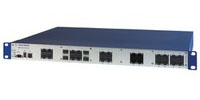
Коммутатор 24-портовый промышленный Hirschmann MACH104-20TX-FR, 942 003-101, 20 портов GE TX, 4 комбинированных порта GE SFP.
Тип: управляемый.
24 порта:
• 20x (10/100/1000 BASE-TX, RJ45)
• 4 гигабитных комбинированных порта (10/100/1000 BASE-TX, RJ45 или 100/1000 BASE-FX, SFP)
Интерфейс V.24: 1 разъем RJ11.
USB-интерфейс: 1 x USB.
Управление: последовательный интерфейс, веб-интерфейс, SNMP V1/V2, ПО для передачи файлов HiVision HTTP/TFTP.
Температура эксплуатации: 0 С — 50 С.
Размеры (Ш х В х Г): 448 мм х 44 мм х 345 мм.
Монтаж в 19-дюймовый шкаф управления
Вес: 4400 грамм.
Класс защиты: IP20.
Вы можете купить свитч MACH104-20TX-FR с доставкой по самой низкой цене. Технические специалисты Bouz Group помогут подобрать коммутаторы или другое оборудование для вашего бизнеса.
Идет загрузка меню,
подождите …
•
Промышленные сети
››
Каталог
››
Офисный Ethernet
››
Коммутатор MACH100
››
MACH 104-20TX-FR
MACH 104-20TX-FR
Коммутатор 2-го уровня с программным обеспечением Professional version с резервным питанием
Технические характеристики
|
Общая информация |
|||||
|
Название |
MACH 104-20TX-FR |
||||
|
Номер по каталогу |
942 003-101 |
||||
|
Интерфейсы |
|||||
|
Количество и тип портов |
|
||||
|
V.24 интерфейс |
1 х RJ-11 |
||||
|
USB интерфейс |
ACA21-USB |
||||
|
Источник питания |
1A на 24 V DC/AC |
||||
|
Электропитание |
|||||
|
Рабочее напряжение |
100 / 240VAC, 47-63Hz (резервное питание) |
||||
|
Потребляемый ток |
0,4А / 0,2А |
||||
|
Условия эксплуатации |
|||||
|
Рабочая температура |
0С до +50С |
||||
|
Физические параметры |
|||||
|
Размеры (ШхВхГ) |
448 мм x 44 мм x 310 мм |
||||
|
Установка |
19’’-стойка или настольное размещение |