-
Contents
-
Table of Contents
-
Troubleshooting
-
Bookmarks
Related Manuals for Hitachi L200 Series
Summary of Contents for Hitachi L200 Series
-
Page 1
L200 Series Inverter Instruction Manual • Single-phase Input 200V Class • Three-phase Input 200V Class • Three-phase Input 400V Class Manual Number: NB660XA After reading this manual, keep it handy for future reference. September 2004 Hitachi Industrial Equipment Systems Co., Ltd. -
Page 3: Safety Messages
L200 Inverter Safety Messages For the best results with the L200 Series inverter, carefully read this manual and all of the warning labels attached to the inverter before installing and operating it, and follow the instructions exactly. Keep this manual handy for quick reference. Definitions and Symbols A safety instruction (message) includes a “Safety Alert Symbol”…
-
Page 4
L200 series equipment. CAUTION: Proper grounds, disconnecting devices and other safety devices and their location are the responsibility of the user and are not provided by Hitachi Industrial Equipment Systems Co., Ltd. CAUTION: Be sure to connect a motor thermal disconnect switch or overload device to the L200 series controller to assure that the inverter will shut down in the event of an overload or an overheated motor. -
Page 5
L200 Inverter WARNING: Rotating shafts and above-ground electrical potentials can be hazardous. Therefore, it is strongly recommended that all electrical work conform to the National Electrical Codes and local regulations. Installation, alignment and maintenance should be performed only by qualified personnel. Factory-recommended test procedures included in the instruction manual should be followed. -
Page 6: Index To Warnings And Cautions In This Manual
Index to Warnings and Cautions in This Manual Cautions and Warnings for Orientation and Mounting Procedures CAUTION: Hazard of electrical shock. Disconnect incoming power ..2–3 before working on this control. Wait five (5) minutes before removing the front cover. CAUTION: Be sure to install the unit on flame-resistant material such as ..
-
Page 7
L200 Inverter WARNING: “Suitable for use on a circuit capable of delivering not more ..2–15 than 5,000 rms symmetrical amperes, 480 V maximum.” For models with suffix H. HIGH VOLTAGE: Be sure to ground the unit. Otherwise, there is a .. -
Page 8
CAUTION: Remarks for using ground fault interrupter breakers in the ..2–19 main power supply: Adjustable frequency inverters with CE-filters (RFI- filter) and shielded (screened) motor cables have a higher leakage current toward Earth GND. Especially at the moment of switching ON this can cause an inadvertent trip of ground fault interrupters. -
Page 9
L200 Inverter Warnings for Configuring Drive Parameters WARNING: When parameter B012, level of electronic thermal setting, is ..3–33 set to motor FLA rating (Full Load Ampere nameplate rating), the inverter provides solid state motor overload protection at 115% of motor FLA or equivalent. -
Page 10
viii WARNING: Be sure not to touch the inside of the energized inverter or to ..4–3 put any conductive object into it. Otherwise, there is a danger of electric shock and/or fire. WARNING: If power is turned ON when the Run command is already .. -
Page 11: General Warnings And Cautions
L200 Inverter Warnings and Cautions for Troubleshooting and Maintenance WARNING: Wait at least five (5) minutes after turning OFF the input ..6–2 power supply before performing maintenance or an inspection. Other- wise, there is the danger of electric shock. WARNING: Make sure that only qualified personnel will perform ..
-
Page 12
CAUTION: Do not stop operation by switching OFF electromagnetic contactors on the primary or secondary sides of the inverter. Ground fault interrupter Power Input L1, L2, L3 U, V, W Motor Inverter When there has been a sudden power failure while an operation instruction is active, then the unit may restart operation automatically after the power failure has ended. -
Page 13
L200 Inverter CAUTION: EFFECTS OF POWER DISTRIBUTION SYSTEM ON INVERTER In the cases below involving a general-purpose inverter, a large peak current can flow on the power supply side, sometimes destroying the converter module: 1. The unbalance factor of the power supply is 3% or higher. 2. -
Page 14
CAUTION: When the EEPROM error E08 occurs, be sure to confirm the setting values again. CAUTION: When using normally closed active state settings (C011 to C015) for exter- nally commanded Forward or Reverse terminals [FW] or [RV], the inverter may start automatically when the external system is powered OFF or disconnected from the inverter! So, do not use normally closed active state settings for Forward or Reverse terminals [FW] or [RV] unless your system design protects against unintended motor… -
Page 15
xiii L200 Inverter Terminal Tightening Torque and Wire Size The wire size range and tightening torque for field wiring terminals are presented in the tables below. Motor Output Power Terminal Torque Input Inverter Model Wiring Size Voltage ft-lbs (N-m) Range (AWG) L200-002NFEF/NFU L200-004NFEF/NFU 0.55… -
Page 16: Motor Overload Protection
7 1/2 L200-055HFEF/HFU L200-075HFEF/HFU Motor Overload Protection Hitachi L200 inverters provide solid state motor overload protection, which depends on the proper setting of the following parameters: • B012 “electronic overload protection” • B212 “electronic overload protection, 2nd motor” Set the rated current [Amperes] of the motor(s) with the above parameters. The setting range is 0.2 * rated current to 1.2 * rated current.
-
Page 17: Table Of Contents
L200 Inverter Table of Contents Safety Messages Hazardous High Voltage General Precautions — Read These First! Index to Warnings and Cautions in This Manual General Warnings and Cautions UL® Cautions, Warnings, and Instructions Table of Contents Revisions xvii Contact Information xviii Chapter 1: Getting Started Introduction…
-
Page 18: Table Of Contents
Connecting the Inverter to ModBus B–3 Network Protocol Reference B–6 ModBus Data Listing B–19 Appendix C: Drive Parameter Settings Tables Introduction C–2 Parameter Settings for Keypad Entry C–2 Appendix D: CE–EMC Installation Guidelines CE–EMC Installation Guidelines D–2 Hitachi EMC Recommendations D–6 Index…
-
Page 19
xvii L200 Inverter Revisions Revision History Table Operation Revision Comments Date of Issue Manual No. Initial release of manual NB660X March 2004 NB660X Revision A April 2004 NB660XA Pages 3–37 to 3–39, B–33 – Added B032 description, made Index entries… -
Page 20: Contact Information
NOTE: To receive technical support for the Hitachi inverter you purchased, contact the Hitachi inverter dealer from whom you purchased the unit, or the sales office or factory contact listed above. Please be prepared to provide the following inverter nameplate information: 1.
-
Page 21: Introduction
Getting Started In This Chapter… page — Introduction …………. — L200 Inverter Specifications ……— Introduction to Variable-Frequency Drives ..— Frequently Asked Questions ……
-
Page 22
• Continuous operation at 100% torque within a 1:10 speed range (6/60 Hz / 5/50 Hz) without motor derating A full line of accessories from Hitachi is available to complete your motor application: • Digital remote operator keypad • Panel-mount keypad bezel kit and DIN rail mounting adapter (35mm rail size) •… -
Page 23
(below left). A cable (part no. ICS–1 or ICS–3, 1m or 3m) connects the modular connectors of the keypad and inverter. Hitachi provides a panel mount keypad kit OPE–SRmini (below, right). It includes the mounting flange, gasket, keypad, and other hardware. You can mount the keypad with the potentiometer for a NEMA1 rated installation. -
Page 24
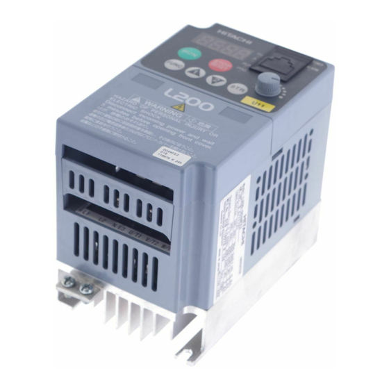
Introduction Inverter Specifications Label The Hitachi L200 inverters have product labels located on the right side of the housing, as pictured below. Be sure to verify that the specifications on the labels match your power source, motor, and application safety requirements. -
Page 25: L200 Inverter Specifications
1–5 L200 Inverter L200 Inverter Specifications Model-specific tables for 200V and 400V class inverters The following tables are specific to L200 inverters for the 200V and 400V class model groups. Note that “General Specifications” on page 1–10 apply to both voltage class groups.
-
Page 26
(for Low Voltage Directive). Note 7: At the rated voltage when using a Hitachi standard 3-phase, 4-pole motor. Note 8: The braking torque via capacitive feedback is the average deceleration torque at the shortest deceleration (stopping from 50/60 Hz as indicated). -
Page 27
1–7 L200 Inverter L200 Inverter Specifications, continued… Item 200V Class Specifications, continued L200 inverters, EU version 015NFEF 022NFEF — — — 200V models USA version 015NFU 022NFU 037LFU 055LFU 075LFU Applicable motor size *2 Rated capacity 230V 12.7 (kVA) 240V 13.3 Rated input voltage 1-phase: 200 to 240V ±10%, 50/60 Hz ±5%,… -
Page 28
1–8 L200 Inverter Specifications Item 400V Class Specifications L200 inverters, EU version 004HFEF 007HFEF 015HFEF 022HFEF 400V models USA version 004HFU 007HFU 015HFU 022HFU Applicable motor size *2 0.75 Rated capacity (460V) kVA Rated input voltage *6 3-phase: 380 to 480V ±10%, 50/60 Hz ±5% Integrated EMC EU version Three phase filter, Category C3 *5… -
Page 29
1–9 L200 Inverter Item 400V Class Specifications, continued L200 inverters, EU version 030HFEF 040HFEF 055HFEF 075HFEF 400V models USA version — 040HFU 055HFU 075HFU Applicable motor size *2 Rated capacity (460V) kVA 10.3 12.7 Rated input voltage *6 3-phase: 380 to 480V ±10%, 50/60 Hz ±5% Integrated EMC EU version Three phase filter, Category C3… -
Page 30: General Specifications
1–10 L200 Inverter Specifications General Specifications The following table applies to all L200 inverters. Item General Specifications Protective housing *1 IP20 Control method Sinusoidal Pulse Width Modulation (PWM) control Carrier frequency 2kHz to 14kHz (default setting: 5kHz) Output frequency range *4 0.5 to 400 Hz Frequency accuracy Digital command: 0.01% of the maximum frequency…
-
Page 31
1–11 L200 Inverter Item General Specifications Other functions AVR function, curved accel/decel profile, upper and lower limiters, 16-stage speed profile, fine adjustment of start frequency, carrier frequency change (2 to 14 kHz) *10, frequency jump, gain and bias setting, process jogging, electronic thermal level adjustment, retry function, trip history monitor, 2nd setting selection, fan ON/OFF selection Protective function… -
Page 32: Introduction To Variable-Frequency Drives
Introduction to Variable-Frequency Drives The Purpose of Motor Speed Control for Industry Hitachi inverters provide speed control for 3-phase AC induction motors. You connect AC power to the inverter, and connect the inverter to the motor. Many applications benefit from a motor with variable speed, in several ways: •…
-
Page 33
Inverter Input and Three-Phase Power The Hitachi L200 Series of inverters includes two sub-groups: the 200V class and the 400V class inverters. The drives described in this manual may be used in either the United States or Europe, although the exact voltage level for commercial power may be slightly different from country to country. -
Page 34
The Hitachi inverter is a rugged and reliable device. The intention is for the inverter to assume the role of controlling power to the motor during all normal operations. There- fore, this manual instructs you not to switch off power to the inverter while the motor is running (unless it is an emergency stop). -
Page 35
For loads that continuously overhaul the motor for extended periods of time, the L200 may not be suitable (contact your Hitachi distributor). For loads that continuously overhaul the motor for extended periods of time, the L200 may not be suitable (contact your Hitachi distributor). -
Page 36
1–16 Introduction to Variable-Frequency Drives Velocity Profiles The L200 inverter is capable of sophisticated speed control. A graphical representation of Set speed Speed that capability will help you understand and configure the associated parameters. This Accel Decel manual makes use of the velocity profile graph used in industry (shown at right). -
Page 37: Frequently Asked Questions
1–17 L200 Inverter Frequently Asked Questions What is the main advantage in using an inverter to drive a motor, compared to alternative solutions? An inverter can vary the motor speed with very little loss of efficiency, unlike mechanical or hydraulic speed control solutions. The resulting energy savings usually pays for the inverter in a relatively short time.
-
Page 38
The greater the number of poles, the slower the top motor speed will be, but it will have higher torque at the base speed. Will I be able to add dynamic (resistive) braking to my Hitachi L200 drive after the initial installation? Yes. -
Page 39
Several options related to electrical noise suppression are available for the Hitachi inverters. How can I know if my application will require any of these options? The purpose of these noise filters is to reduce the inverter electrical noise so the operation of nearby electrical devices is not affected. -
Page 41
Inverter Mounting and Installation In This Chapter..page — Orientation to Inverter Features …… — Basic System Description ……. — Step-by-Step Basic Installation……— Powerup Test ……….— Using the Front Panel Keypad …… -
Page 42: Orientation To Inverter Features
The electronics housing and front panel are built onto the front of the heat sink. Inverter Keypad — The inverter uses a digital POWER operator interface, or keypad. The four-digit HITACHI ALARM display can show a variety of performance 5 0.0 parameters. LEDs indicate whether the display units are Hertz or Amperes.
-
Page 43
2–3 L200 Inverter Front Housing Cover HIGH VOLTAGE: Hazard of electrical shock. Disconnect incoming power before working on this control. Wait five (5) minutes before removing the front cover. Housing Cover Removal — The front housing cover is held in place by two pairs of tabs. Since these are hidden from view, it is good to become familiar with their locations before attempting to remove the cover. -
Page 44
2–4 Orientation to Inverter Features Logic Connector Introduction After removing the front housing cover, take a moment to become familiar with the connectors, as shown below. Relay output Logic and analog contacts signal connections… -
Page 45: Connecting The Inverter To Modbus
2–5 L200 Inverter DIP Switch Introduction The inverter has three (3) internal DIP switches, located to the right of the logic connec- tors as shown below. This section provides an introduction, and refers you to other chapters that discuss each DIP switch in depth. The SR/SK (Source/Sink) DIP switch configures the inverter’s intelligent inputs for sinking or sourcing type circuit.
-
Page 46
2–6 Orientation to Inverter Features Power Wiring Access — First, ensure no power source of any kind is connected to the inverter. If power has been connected, wait five minutes after powerdown and verify the Power LED is OFF to proceed. After removing the front housing cover, the housing partition that covers the power wiring exit will be able to slide upward as shown to the right. -
Page 47: Basic System Description
2–7 L200 Inverter Basic System Description A motor control system will obviously include a motor and inverter, as well as a breaker or fuses for safety. If you are connecting a motor to the inverter on a test bench just to get started, that’s all you may need for now.
-
Page 48: Step-By-Step Basic Installation
2–8 Step-by-Step Basic Installation WARNING: In the cases below involving a general-purpose inverter, a large peak current can flow on the power supply side, sometimes destroying the converter module: 1.The unbalance factor of the power supply is 3% or higher. 2.The power supply capacity is at least 10 times greater than the inverter capacity (or the power supply capacity is 500 kVA or more).
-
Page 49: Choosing A Mounting Location
2–9 L200 Inverter Choosing a Mounting Location Step 1: Study the following caution messages associated with mounting the inverter. This is the time when mistakes are most likely to occur that will result in expensive rework, equipment damage, or personal injury. CAUTION: Be sure to install the unit on flame-resistant material such as a steel plate.
-
Page 50
Air flow Clear area 10 cm (3.94”) minimum POWER HITACHI ALARM 5 0.0 STOP RESET FUNC. L200 5 cm (1.97”) -
Page 51
2–11 L200 Inverter Check Inverter Dimensions Step 4: Locate the applicable drawing on the following pages for your inverter. Dimensions are given in millimeters (inches) format. L200–002NFEF, –002NFU, –004NFEF, –004NFU, –005NFEF 5(0.20) 5(0.20) 67(2.64) 80(3.15) 93(3.66), -002xxx models 107(4.21), -004xxx models 130(5.12), -005xxx models NOTE: Some inverter housings require two mounting screws, while others require four. -
Page 52
2–12 Step-by-Step Basic Installation Dimensional drawings, continued… L200–007NFEF, –007NFU, –011NFEF, –015NFEF, –015NFU, –022NFEF, –022NFU, –037LFU, –015HFEF, –015HFU, 022HFEF, 022HFU, 030HFEF, –040HFEF, –040HFU Φ 5(0.20) 98(3.86) 5(0.20) 110(4.33) -
Page 53
2–13 L200 Inverter Dimensional drawings, continued… L200–004HFEF, –004HFU 2-Φ5(0.20) 5(0.20) 98(3.86) 110(4.33) -
Page 54
2–14 Step-by-Step Basic Installation Dimensional drawings, continued… L200–007HFEF, –007HFU 2-Φ5(0.20) 98(3.86) 5(0.20) 110(4.33) -
Page 55
2–15 L200 Inverter Prepare for Wiring Step 5: It is very important to perform the wiring steps carefully and correctly. Before proceeding, please study the caution and warning messages below. WARNING: “Use 60/75°C Cu wire only” or equivalent. WARNING: “Open Type Equipment.” WARNING: “Suitable for use on a circuit capable of delivering not more than 5,000 rms symmetrical amperes, 240 V maximum.”… -
Page 56
2–16 Step-by-Step Basic Installation Determining Wire and Fuse Sizes The maximum motor currents in your application determines the recommended wire size. The following table gives the wire size in AWG. The “Power Lines” column applies to the inverter input power, output wires to the motor, the earth ground connection, and any other component shown in the “Basic System Description”… -
Page 57
2–17 L200 Inverter Terminal Dimensions and Torque Specs The terminal screw dimensions for all L200 inverters are listed in table below. This information is useful in sizing spade lug or ring lug connectors for wire terminations. CAUTION: Fasten the screws with the specified fastening torque in the table below. Check for any loosening of screws. -
Page 58
2–18 Step-by-Step Basic Installation Please use the terminal arrangement below corresponding to your inverter model. Inverter models L200–002NFEF/NFU, –004NFEF/NFU, –005NFEF Jumper – L2 N/L3 U/T1 V/T2 W/T3 Chassis Ground Inverter models L200–007NFEF to –022NFEF, –037LFU, –004HFEF/HFU to –040HFEF/HFU Jumper – Chassis U/T1 V/T2 W/T3… -
Page 59
2–19 L200 Inverter CAUTION: Be sure not to connect an AC power supply to the output terminals. Other- wise, there is the possibility of damage to the inverter and the danger of injury and/or fire. L200 Inverter Power Input Output to Motor CAUTION: Remarks for using ground fault interrupter breakers in the main power supply: Adjustable frequency inverters with CE-filters (RFI-filter) and shielded (screened) motor… -
Page 60
2–20 Step-by-Step Basic Installation Wire the Inverter Output to Motor Step 7: The process of motor selection is beyond the scope of this manual. However, it must be an AC induction motor with three phases. It should also come with a chassis ground lug. -
Page 61: Powerup Test
3. Get an introduction to the use of the built-in operator keypad. The powerup test gives you an important starting point to ensure a safe and successful application of the Hitachi inverter. We highly recommend performing this test before proceeding to the other chapters in this manual.
-
Page 62
2–22 Powerup Test Pre-test and Operational Precautions The following instructions apply to the powerup test, or to any time the inverter is powered and operating. Please study the following instructions and messages before proceeding with the powerup test. 1. The power supply must have fusing suitable for the load. Check the fuse size chart presented in Step 5, if necessary. -
Page 63: Using The Front Panel Keypad
The display is used in programming the inverter’s parameters, as well as monitor- ing specific parameter values during operation. Power LED Display Units (Hertz / Amperes) LEDs Serial port Alarm LED POWER Parameter Display HITACHI ALARM Run/Stop LED 5 0.0 Program/Monitor LED Run Key Enable LED STOP RESET Potentiometer Enable LED FUNC.
-
Page 64
Using the Front Panel Keypad Keys, Modes, and Parameters The purpose of the keypad is to provide a way to change POWER HITACHI modes and parameters. The term function applies to both ALARM 0 0 1 monitoring modes and parameters. These are all accessible… -
Page 65
2–25 L200 Inverter Keypad Navigational Map The L200 Series inverter drives have many programmable functions and parameters. Chapter 3 will cover these in detail, but you need to access just a few items to perform the powerup test. The menu structure makes use of function codes and parameter codes to allow programming and monitoring with only a 4-digit display and a few keys and LEDs. -
Page 66
Potentiometer Enable LED The inverter output frequency can be set from several sources, including an analog input, memory setting, POWER HITACHI or the network, for example. The powerup test uses ALARM 5 0.0 the keypad potentiometer as the speed control source for your convenience. -
Page 67
Run Key Enable LED command causes the inverter to accelerate the motor to POWER the selected speed. The Run command can arrive from HITACHI ALARM various sources, including the control terminals, the Run 5 0.0 key on the keypad, or the network. In the figure to the… -
Page 68
2–28 Using the Front Panel Keypad Set the Motor Base Frequency — The motor is designed to operate at a specific AC frequency. Most commercial motors are designed for 50/60 Hz operation. First, check the motor specifications. Then follow the steps below to verify the setting or correct it for your motor. -
Page 69
2–29 L200 Inverter Action Display Func./Parameter (Starting point) Base frequency setting A 0 0 3 AVR voltage select key and hold until—> Press the A 0 8 2 Default values for AVR voltage: key. Press the FUNC. 2 3 0 200V class = 230VAC 400V class = 400VAC (–xxxFEF) 400V class = 460VAC (–xxxFU) -
Page 70
2–30 Using the Front Panel Keypad Set the Number of Motor Poles — The motor’s internal winding arrangement deter- mines its number of magnetic poles. The specifications label on the motor usually indicates the number of poles. For proper operation, verify the parameter setting matches the motor poles. -
Page 71
Monitoring Parameters with the Display After using the keypad for parameter editing, it’s a good idea to switch the inverter from POWER HITACHI ALARM Program Mode to Monitor Mode. The PRG 5 0.0 LED will be OFF, and the Hertz or Ampere LED indicates the display units. -
Page 72
NOTE: Some factory automation devices such as PLCs have alternate Run/Program modes; the device is in either one mode or the other. In the Hitachi inverter, however, Run Mode alternates with Stop Mode, and Program Mode alternates with Monitor Mode. -
Page 73: Configuring Drive Parameters
Configuring Drive Parameters In This Chapter..page — Choosing a Programming Device ….— Using Keypad Devices ……..— “D” Group: Monitoring Functions….. — “F” Group: Main Profile Parameters ….— “A” Group: Standard Functions ….. — “B” Group: Fine Tuning Functions ….
-
Page 74: Choosing A Programming Device
Choosing a Programming Device Introduction Hitachi variable frequency drives (inverters) use the latest electronics technology for getting the right AC waveform to the motor at the right time. The benefits are many, including energy savings and higher machine output or productivity. The flexibility required to handle a broad range of applications has required ever more configurable options and parameters—inverters are now a complex industrial automation component.
-
Page 75: Using Keypad Devices
Power LED Display Units (Hertz / Amperes) LEDs Serial port Alarm LED POWER Parameter Display HITACHI ALARM Run/Stop LED 5 0.0 Program/Monitor LED Run Key Enable LED STOP RESET Potentiometer Enable LED FUNC.
-
Page 76
3–4 Using Keypad Devices Keypad Navigational Map You can use the inverter’s front panel keypad to navigate to any parameter or function. The diagram below shows the basic navigational map to access these items. Monitor Mode Program Mode PRG LED=OFF PRG LED=ON Display Data Select Parameter… -
Page 77
3–5 L200 Inverter Operational Modes The RUN and PRG LEDs tell just part of the story; Run Mode and Program Modes are independent STOP RESET Stop modes, not opposite modes. In the state diagram to the right, Run alternates with Stop, and Program Mode alternates with Monitor Mode. -
Page 78: D» Group: Monitoring Functions
3–6 “D” Group: Monitoring Functions “D” Group: Monitoring Functions You can access important system parameter values with the “D” Group monitoring functions, whether the inverter is in Run Mode or Stop Mode. After selecting the function code number for the parameter you want to monitor, press the Function key once to show the value on the display.
-
Page 79
3–7 L200 Inverter “D” Function Mode Units Func. Name / Description Edit Code SRW Display D007 Scaled output frequency Displays the output frequency — Hz times monitor scaled by the constant in B086. constant Decimal point indicates range: F-Cnv 00000.00 XX.XX 0.00 to 99.99 XXX.X 100.0 to 999.9 XXXX. -
Page 80
3–8 “D” Group: Monitoring Functions Local Monitoring During Network Operation The L200 inverter’s serial port may be connected to a network or to an external digital operator. During those times, the inverter keypad keys will not function (except for the Stop key). -
Page 81: F» Group: Main Profile Parameters
3–9 L200 Inverter “F” Group: Main Profile Parameters The basic frequency (speed) profile is Output defined by parameters contained in the F002 F003 frequency “F” Group as shown to the right. The set running frequency is in Hz, but accelera- F001 tion and deceleration are specified in the time duration of the ramp (from zero to…
-
Page 82: A» Group: Standard Functions
3–10 “A” Group: Standard Functions “A” Group: Standard Functions Control Source Settings The inverter provides flexibility in how you control Run/Stop operation and set the output frequency (motor speed). It has other control sources that can override the A001/ A002 settings. Parameter A001 sets the source selection for the inverter’s output frequency.
-
Page 83
3–11 L200 Inverter Run Command Source Setting — For parameter A002, the following table provides a further description of each option, and a reference to other page(s) for more information Code Run Command Source Refer to page(s)… Control terminal — The [FW] or [RV] input terminals control 4–12 3–43 Run/Stop operation… -
Page 84
3–12 “A” Group: Standard Functions The inverter has other control sources that can temporarily override the parameter A001 setting, forcing a different output frequency source. The following table lists all frequency source setting methods and their relative priority (“1” is the highest priority). Priority A001 Frequency Source Setting Method Refer to page… -
Page 85
3–13 L200 Inverter Basic Parameter Settings These settings affect the most fundamental behavior of the inverter—the outputs to the motor. The frequency of the inverter’s AC output determines the motor speed. You may select from three different sources for the reference speed. During application develop- ment you may prefer using the potentiometer, but you may switch to an external source (control terminal setting) in the finished application, for example. -
Page 86
3–14 “A” Group: Standard Functions Analog Input Settings The inverter has the capability to accept an external analog input that can command the output frequency to the motor. Voltage input (0 –10V) and current input (4–20mA) are available on separate terminals ([O] and [OI], respectively). Terminal [L] serves as signal ground for the two analog inputs. -
Page 87
3–15 L200 Inverter “A” Function Defaults Mode Func. Name / –FEF –FU Description Units Edit Code SRW Display (EU) (USA) A005 [AT] selection Four options, select codes: 00… Select between [O] and AT-Slct O/OI [OI] at [AT] 01… [O] + [OI] ([AT] input is ignored) 02… -
Page 88
3–16 “A” Group: Standard Functions The jog speed setting is used whenever the Jog command is active. The jog speed setting range is arbitrarily limited to 10 Hz, to provide safety during manual operation. The acceleration to the jog frequency is instantaneous, but you can choose from three modes for the best method for stopping the jog operation. -
Page 89
3–17 L200 Inverter Torque Control Algorithms The inverter generates the motor output Inverter Torque Control Algorithms according to the V/f algorithm selected. Parameter A044 selects the inverter algorithm V/f control, for generating the frequency output, as shown constant torque in the diagram to the right (A244 for 2nd Output motor). -
Page 90
3–18 “A” Group: Standard Functions Be aware that running the motor at a low speed for a long time can cause motor overheating. This is particularly true when manual torque boost is ON, or if the motor relies on a built-in fan for cooling. NOTE: Manual torque boost applies only to constant torque (A044=00) and variable torque (A044=01) V/f control. -
Page 91
3–19 L200 Inverter “A” Function Defaults Mode Func. Name / –FEF –FU Description Units Edit Code SRW Display (EU) (USA) A244 V/f characteristic curve Two available V/f curves; — selection, 2nd motor three select codes: 00… Constant torque 2CTRL C-TRQ 01… -
Page 92
3–20 “A” Group: Standard Functions DC Braking Settings The DC braking feature can provide additional stopping torque when Running Free run DC braking compared to a normal deceleration to a stop. DC braking is particularly useful at low speeds when normal decelera- tion torque is minimal. -
Page 93
3–21 L200 Inverter Frequency-related Functions Frequency Limits – Upper and lower Output limits can be imposed on the inverter frequency output frequency. These limits will apply Upper regardless of the source of the speed refer- A061 limit ence. You can configure the lower frequency limit to be greater than zero as Settable shown in the graph. -
Page 94
3–22 “A” Group: Standard Functions Jump Frequencies – Some motors or machines exhibit resonances at particular speed(s), which can be destructive for prolonged running at those speeds. The inverter has up to three jump frequencies as shown in the graph. The hysteresis around the jump frequencies causes the inverter output to skip around the sensitive frequency values. -
Page 95: Pid Control
3–23 L200 Inverter PID Control When enabled, the built-in PID loop calculates an ideal inverter output value to cause a loop feedback process variable (PV) to move closer in value to the setpoint (SP). The frequency command serves as the SP. The PID loop algorithm will read the analog input for the process variable (you specify the current or voltage input) and calculate the output.
-
Page 96
3–24 “A” Group: Standard Functions Automatic Voltage Regulation (AVR) Function The automatic voltage regulation (AVR) feature keeps the inverter output waveform at a relatively constant amplitude during power input fluctuations. This can be useful if the installation is subject to input voltage fluctuations. However, the inverter cannot boost its motor output to a voltage higher than the power input voltage. -
Page 97
3–25 L200 Inverter Second Acceleration and Deceleration Functions The L200 inverter features two-stage acceleration and deceleration ramps. This gives flexibility in the profile shape. You can specify the frequency transition point, the point at which the standard acceleration (F002) or deceleration (F003) changes to the second acceleration (A092) or deceleration (A093). -
Page 98
3–26 “A” Group: Standard Functions “A” Function Defaults Mode Func. Name / –FEF –FU Description Units Edit Code SRW Display (EU) (USA) A095 Acc1 to Acc2 frequency Output frequency at which transition point Accel1 switches to Accel2, range is 0.0 to 400.0 Hz ACC CHfr0000.0Hz A295 Acc1 to Acc2 frequency Output frequency at which… -
Page 99
3–27 L200 Inverter Accel/Decel Standard acceleration and deceleration is Output linear. The inverter CPU can also calculate frequency Accel. curve selection an S-curve acceleration or deceleration curve as shown. This profile is useful for Target freq. favoring the load characteristics in particu- lar applications. -
Page 100
3–28 “A” Group: Standard Functions Additional Analog Input Settings Input Range Settings – The parameters in the following table adjust the input charac- teristics of the analog current input. When using the inputs to command the inverter output frequency, these parameters adjust the starting and ending ranges for the current, as well as the output frequency range. -
Page 101
3–29 L200 Inverter Analog Input Calculate Function – The inverter can mathematically combine two input sources into one value. The Calculate function can either add, subtract, or multiply the two selected sources. This provides the flexibility needed by various applica- tions.You can use the result for the output frequency setting (use A001=10) or for the PID Process Variable (PV) input (use A075=03). -
Page 102
3–30 “A” Group: Standard Functions ADD Frequency – The inverter can add or subtract an offset value to the output frequency setting which is specified by A001 (will work with any of the five possible sources). The ADD Frequency is a value you can store in parameter A145. The ADD Frequency is summed with or subtracted from the output frequency setting only when the [ADD] terminal is ON. -
Page 103: B» Group: Fine Tuning Functions
3–31 L200 Inverter “B” Group: Fine Tuning Functions The “B” Group of functions and parameters adjust some of the more subtle but useful aspects of motor control and system configuration. Automatic Restart Mode The restart mode determines how the inverter will resume operation after a fault causes a trip event.
-
Page 104
3–32 “B” Group: Fine Tuning Functions “B” Function Defaults Mode Func. Name / –FEF –FU Description Units Edit Code SRW Display (EU) (USA) B001 Selection of automatic Select inverter restart method, — restart mode four option codes: 00… Alarm output after trip, IPS POWR no automatic restart 01… -
Page 105
3–33 L200 Inverter you must set the thermal overload threshold in terms of current (amperes) for parameter B012. The range is 20% to 120% of the rated current for each inverter model. If the current exceeds the level you specify, the inverter will trip and log an event (error E05) in the history table. -
Page 106
3–34 “B” Group: Fine Tuning Functions Overload Restriction If the inverter’s output current exceeds a Motor preset current level you specify during Current acceleration or constant speed, the overload Restriction area B022 restriction feature automatically reduces the output frequency to restrict the overload. This feature does not generate an alarm or trip event. -
Page 107
3–35 L200 Inverter Software Lock Mode The software lock function keeps personnel from accidentally changing parameters in the inverter memory. Use B031 to select from various protection levels. The table below lists all combinations of B031 option codes and the ON/OFF state of the [SFT] input. Each Check or Ex Mode indicates whether the corresponding parameter(s) can be edited. -
Page 108
3–36 “B” Group: Fine Tuning Functions “B” Function Defaults Mode Func. Name / –FEF –FU Description Units Edit Code SRW Display (EU) (USA) B031 Software lock mode Prevents parameter changes, in — selection four options, option codes: 00… all parameters except S-Lock B031 are locked when [SFT] terminal is ON… -
Page 109
3–37 L200 Inverter Miscellaneous Settings The miscellaneous settings include scaling factors, initialization modes, and others. This section covers some of the most important settings you may need to configure. B032: Reactive current setting – Each L200 inverter model is designed for a particular motor size (hp/power rating). -
Page 110
3–38 “B” Group: Fine Tuning Functions NOTE: Parameter setting B032 affects the inverter’s electronic thermal protection (B012 setting) and its overload restriction function (B022 setting). NOTE: For low B032 values, the effect on the electronic thermal protection and overload restriction functions may not be accurate. B080: [AM] analog signal gain –… -
Page 111
3–39 L200 Inverter “B” Function Defaults Mode Func. Name / –FEF –FU Description Units Edit Code SRW Display (EU) (USA) B032 Reactive current setting Calibrate detection of motor’s 100. 100. reactive (no load) current for Io-SET 00100% current monitor, electric thermal setting, and overload restriction setting. -
Page 112
3–40 “B” Group: Fine Tuning Functions B091/B088: Stop Mode / Restart Mode Configuration – You can configure how the inverter performs a standard stop (each time Run FWD and REV signals turn OFF). Setting B091 determines whether the inverter will control the deceleration, or whether it will perform a free-run stop (coast to a stop). -
Page 113
3–41 L200 Inverter “B” Function Defaults Mode Func. Name / –FEF –FU Description Units Edit Code SRW Display (EU) (USA) B088 Restart mode after FRS Selects how the inverter — resumes operation when the RUN FRS free-run stop (FRS) is cancelled, two options: 00… -
Page 114: C» Group: Intelligent Terminal Functions
3–42 “C” Group: Intelligent Terminal Functions “C” Group: Intelligent Terminal Functions The five input terminals [1], [2], [3], [4], and [5] can be configured for any of 19 different functions. The next two tables show how to configure the five terminals. The inputs are logical, in that they are either OFF or ON.
-
Page 115
3–43 L200 Inverter The input logic convention is programmable for each of the six inputs. Most inputs default to normally open (active high), but you can select normally closed (active low) in order to invert the sense of the logic. “C”… -
Page 116
3–44 “C” Group: Intelligent Terminal Functions Input Function Summary Table – This table shows all twenty-four intelligent input functions at a glance. Detailed descriptions of these functions, related parameters and settings, and example wiring diagrams are in “Using Intelligent Input Terminals” on page 4–9. -
Page 117
3–45 L200 Inverter Input Function Summary Table Option Terminal Function Name Description Code Symbol Unattended Start On powerup, the inverter will not resume a Run Protection command (mostly used in the US) On powerup, the inverter will resume a Run command that was active before power loss Software Lock The keypad and remote programming devices… -
Page 118
3–46 “C” Group: Intelligent Terminal Functions Input Function Summary Table Option Terminal Function Name Description Code Symbol PIDC PID Reset Resets the PID loop controller. The main conse- quence is that the integrator sum is forced to zero. No effect on PID loop controller Remote Control Accelerates (increases output frequency) motor UP Function (motor-… -
Page 119
3–47 L200 Inverter Output Terminal Configuration The inverter provides configuration for logic (discrete) and analog outputs, shown in the table below. “C” Function Defaults Mode Func. Name / –FEF –FU Description Units Edit Code SRW Display (EU) (USA) C021 Terminal [11] function —… -
Page 120
3–48 “C” Group: Intelligent Terminal Functions Output Function Summary Table – This table shows all ten functions for the logical outputs (terminals [11], [12]) at a glance. Detailed descriptions of these functions, related parameters and settings, and example wiring diagrams are in “Using Intelligent Output Terminals”… -
Page 121
3–49 L200 Inverter Output Function Summary Table Option Terminal Function Name Description Code Symbol Logic Output when the Boolean operation specified by C143 Function has a logical “1” result when the Boolean operation specified by C143 has a logical “0” result Analog Function Summary Table –… -
Page 122
3–50 “C” Group: Intelligent Terminal Functions The Error for the PID loop is the magni- PID Error (PV–SP) deviation threshold tude (absolute value) of the difference Output between the Setpoint (desired value) and Process Variable (actual value). The PID C044 output deviation signal [OD] (output terminal function option code 04) indicates when the error magnitude has… -
Page 123
3–51 L200 Inverter Network Communication Settings The following table lists parameters that configure the inverter’s serial communications port. The settings affect how the inverter communicates with a digital operator (such as SRW–0EX), as well as a ModBus network (for networked inverter applications). The settings cannot be edited via the network, in order to ensure network reliability. -
Page 124
3–52 “C” Group: Intelligent Terminal Functions Analog Signal Calibration Settings The functions in the following table configure the signals for the analog output termi- nals. Note that these settings do not change the current/voltage or sink/source character- istics—only the zero and span (scaling) of the signals. “C”… -
Page 125
3–53 L200 Inverter Miscellaneous Functions The following table contains miscellaneous functions not in other function groups. “C” Function Defaults Mode Func. Name / –FEF –FU Description Units Edit Code SRW Display (EU) (USA) C091 Debug mode enable Displays debug parameters. —… -
Page 126
3–54 “C” Group: Intelligent Terminal Functions Output Logic and Timing Logic Output Function – The inverter has a built-in logic output feature. You can select any two of the other nine intelligent output options for internal inputs. Then, configure the logic function to apply the logical AND, OR, or XOR (exclusive OR) operator as desired to the two inputs. -
Page 127
3–55 L200 Inverter “C” Function Defaults Mode Func. Name / –FEF –FU Description Units Edit Code SRW Display (EU) (USA) C143 Logic function select Applies a logic function to — calculate [LOG] output state, LogicOPE three options: 00… [LOG] = A AND B 01… -
Page 128: H» Group: Motor Constants Functions
3–56 “H” Group: Motor Constants Functions “H” Group: Motor Constants Functions The “H” Group parameters configure the Inverter Torque Control Algorithms inverter for the motor characteristics. You must manually set H003 and H004 values to V/f control, match the motor. Parameter H006 is factory- constant torque set.
-
Page 129
Operations and Monitoring In This Chapter..page — Introduction …………. — Connecting to PLCs and Other Devices ..— Control Logic Signal Specifications ….— Intelligent Terminal Listing……. — Using Intelligent Input Terminals ….. — Using Intelligent Output Terminals ….—… -
Page 130
4–2 Introduction Introduction The previous material in Chapter 3 gave a reference listing of all the programmable functions of the inverter. We suggest that you first scan through the listing of inverter functions to gain a general familiarity. This chapter will build on that knowledge in the following ways: 1. -
Page 131
4–3 L200 Inverter Warning Messages for Operating Procedures Before continuing, please read the following Warning messages. WARNING: Be sure to turn ON the input power supply only after closing the front case. While the inverter is energized, be sure not to open the front case. Otherwise, there is the danger of electric shock. -
Page 132: Connecting To Plcs And Other Devices
Connecting to PLCs and Other Devices Connecting to PLCs and Other Devices Hitachi inverters (drives) are useful in many types of applications. During installation, the inverter keypad (or other programming device) will facilitate the initial configura- tion. After installation, the inverter will generally receive its control commands through the control logic connector or serial interface from another controlling device.
-
Page 133
4–5 L200 Inverter Example Wiring Diagram The schematic diagram below provides a general example of logic connector wiring, in addition to basic power and motor wiring covered in Chapter 2. The goal of this chapter is to help you determine the proper connections for the various terminals shown below for your specific application needs. -
Page 134: Control Logic Signal Specifications
4–6 Control Logic Signal Specifications Control Logic Signal Specifications The control logic connectors are located just behind the front housing cover. The relay contacts are just to the left of the logic connectors. Connector labeling is shown below. Relay contacts Analog Analog Logic…
-
Page 135: Intelligent Terminal Listing
4–7 L200 Inverter Intelligent Terminal Listing Intelligent Inputs Use the following table to locate pages for intelligent input material in this chapter. Intelligent INPUTS Symbol Code Name Page Forward Run/Stop 4–12 Reverse Run/Stop 4–12 Multi-speed Select, Bit 0 (LSB) 4–13 Multi-speed Select, Bit 1 4–13 Multi-speed Select, Bit 2…
-
Page 136
4–8 Intelligent Terminal Listing Intelligent Outputs Use the following table to locate pages for intelligent output material in this chapter. Intelligent OUTPUTS Symbol Code Name Page Run Signal 4–37 Frequency Arrival Type 1 – Constant Speed 4–38 Frequency Arrival Type 2 – Over-frequency 4–38 Overload Advance Notice Signal 4–40… -
Page 137: Using Intelligent Input Terminals
4–9 L200 Inverter Using Intelligent Input Terminals Terminals [1], [2], [3], [4], and [5] are identical, programmable inputs for general use. The input circuits can use the inverter’s internal (isolated) +24V field supply or an external power supply. This section describes input circuits operation and how to connect them properly to switches or transistor outputs on field devices.
-
Page 138
4–10 Using Intelligent Input Terminals The two diagrams below show input wiring circuits using the inverter’s internal +24V supply. Each diagram shows the connection for simple switches, or for a field device with transistor outputs. Note that in the lower diagram, it is necessary to connect terminal [L] only when using the field device with transistors. -
Page 139
4–11 L200 Inverter The two diagrams below show input wiring circuits using an external supply. If using the upper wiring diagram, be sure to use a diode with the external supply. This will prevent a power supply contention in case the SR/SK switch is accidentally placed in the incorrect position. -
Page 140
4–12 Using Intelligent Input Terminals Forward Run/Stop and Reverse Run/Stop Commands: When you input the Run command via the terminal [FW], the inverter executes the Forward Run command (high) or Stop command (low). When you input the Run command via the terminal [RV], the inverter executes the Reverse Run command (high) or Stop command (low). -
Page 141
4–13 L200 Inverter Multi-Speed Select The inverter can store up to 16 different target frequencies (speeds) that the motor output uses for Input Function steady-state run condition. These speeds are acces- Multi- speed sible through programming four of the intelligent CF4 CF3 CF2 CF1 terminals as binary-encoded inputs CF1 to CF4 per Speed 0… -
Page 142
4–14 Using Intelligent Input Terminals Option Terminal Input Function Name Description Code Symbol State C001, C002, C003, C004, Example (some CF inputs require input Valid for inputs: C005 configuration; some are default inputs—see page 3–42): F001, A001 = 02, Required settings: (MSB) (LSB) A020 to A035… -
Page 143
4–15 L200 Inverter Jogging Command The Jog input [JG] is used to command the [JG] motor to rotate slowly in small increments for manual operation. The speed is limited to [FW], [RV] 10 Hz. The frequency for the jogging opera- tion is set by parameter A038. -
Page 144
4–16 Using Intelligent Input Terminals External Signal for DC Braking When the terminal [DB] is turned ON, the Scenario 1 DC braking feature is enabled. Set the follow- ing parameters when the external DC braking [FW, RV] terminal [DB] is to be used: •… -
Page 145
4–17 L200 Inverter Set Second Motor If you assign the [SET] function to an intelligent input terminal, you can select between two sets of motor parameters. The second parameters store an alternate set of motor characteristics. When the terminal [SET] is turned ON, the inverter will use the second set of parameters to generate the frequency output to the motor. -
Page 146
4–18 Using Intelligent Input Terminals Two-stage Acceleration and Deceleration When terminal [2CH] is turned ON, the Output target inverter changes the rate of acceleration and frequency frequency deceleration from the initial settings (F002 second and F003) to use the second set of accelera- initial tion/deceleration values. -
Page 147
4–19 L200 Inverter Free-run Stop When the terminal [FRS] is turned ON, the inverter stops the output and the motor enters the free-run state (coasting). If terminal [FRS] is turned OFF, the output resumes sending power to the motor if the Run command is still active. The free-run stop feature works with other parameters to provide flexibility in stopping and starting motor rotation. -
Page 148: External Trip
4–20 Using Intelligent Input Terminals External Trip When the terminal [EXT] is turned ON, the inverter enters the trip state, indicates error code E12, and stops the output. This is a general purpose interrupt type feature, and the meaning of the error depends on what you connect to the [EXT] terminal. Even if the [EXT] input is turned OFF, the inverter remains in the trip state.
-
Page 149: Unattended Start Protection
4–21 L200 Inverter Unattended Start Protection If the Run command is already set when power is turned ON, the inverter starts running immediately after powerup. The Unattended Start Protection (USP) function prevents that automatic startup, so that the inverter will not run without outside intervention. When USP is active and you need to reset an alarm and resume running, either turn the Run command OFF, or perform a reset operation by the terminal [RS] input or the keypad Stop/reset key.
-
Page 150: Software Lock
4–22 Using Intelligent Input Terminals Software Lock When the terminal [SFT] is turned ON, the data of all the parameters and functions (except the output frequency, depending on the setting of B031) is locked (prohibited from editing). When the data is locked, the keypad keys cannot edit inverter parameters. To edit parameters again, turn OFF the [SFT] terminal input.
-
Page 151
4–23 L200 Inverter Analog Input Current/Voltage Select The [AT] terminal selects whether the inverter uses the voltage [O] or current [OI] input terminals for external frequency control. When intelligent input [AT] is ON, you can set the output frequency by applying a current input signal at [OI]-[L]. When the [AT] input is OFF, you can apply a voltage input signal at [O]-[L] to set the output frequency. -
Page 152: Reset Inverter
4–24 Using Intelligent Input Terminals Reset Inverter The [RS] terminal causes the inverter to 12 ms execute the reset operation. If the inverter is minimum in Trip Mode, the reset cancels the Trip state. [RS] When the signal [RS] is turned ON and OFF, approx.
-
Page 153
4–25 L200 Inverter Thermistor Thermal Protection Motors that are equipped with a thermistor can be protected from overheating. Input terminal [5] has the unique ability to sense a thermistor resistance. When the resistance value of the thermistor connected to terminal [TH] (6) and [L] is more than 3 k Ω ±10%, the inverter enters the Trip Mode, turns OFF the output to the motor, and indicates the trip status E35. -
Page 154
4–26 Using Intelligent Input Terminals Three-wire Interface Operation The 3-wire interface is an industry standard motor control interface. This function uses two inputs for momentary contact start/stop control, and a third for selecting forward or reverse direction. To implement the 3-wire interface, assign 20 [STA] (Start), 21 [STP] (Stop), and 22 [F/R] (Forward/Reverse) to three of the intelligent input terminals. -
Page 155
4–27 L200 Inverter The diagram below shows the use of 3-wire control. STA (Start Motor) is an edge-sensi- tive input; an OFF-to-ON transition gives the Start command. The control of direction is level-sensitive, and the direction may be changed at any time. STP (Stop Motor) is also a level-sensitive input. -
Page 156
4–28 Using Intelligent Input Terminals PID ON/OFF and PID Clear The PID loop function is useful for controlling motor speed to achieve constant flow, pressure, temperature, etc. in many process applications. The PID Disable function temporarily suspends PID loop execution via an intelligent input terminal. It overrides the parameter A071 (PID Enable) to stop PID execution and return to normal motor frequency output characteristics. -
Page 157
4–29 L200 Inverter Remote Control Up and Down Functions The [UP] [DWN] terminal functions can adjust the output frequency for remote control while the motor is running. The acceleration time and deceleration time of this function is same as normal operation ACC1 and DEC1 (2ACC1,2DEC1). The input terminals operate according to these principles: •… -
Page 158
4–30 Using Intelligent Input Terminals It is possible for the inverter to retain the frequency set from the [UP] and [DWN] termi- nals through a power loss. Parameter C101 enables/disables the memory. If disabled, the inverter retains the last frequency before an UP/DWN adjustment. Use the [UDC] terminal to clear the memory and return to the original set output frequency. -
Page 159
4–31 L200 Inverter Force Operation from Digital Operator This function permits a digital operator interface to override the following two settings in the inverter: • A001 — Frequency source setting • A002 — Run command source setting When using the [OPE] terminal input, typically A001 and A002 are configured for sources other than the digital operator interface for the output frequency and Run command sources, respectively. -
Page 160: Add Frequency Enable
4–32 Using Intelligent Input Terminals ADD Frequency Enable The inverter can add or subtract an offset value to the output frequency setting which is specified by A001 (will work with any of the five possible sources). The ADD Frequency is a value you can store in parameter A145. The ADD Frequency is summed with or subtracted from the output frequency setting only when the [ADD] terminal is ON.
-
Page 161: Force Terminal Mode
4–33 L200 Inverter Force Terminal Mode The purpose of this intelligent input is to allow a device to force the inverter to allow control of the following two parameters via the control terminals: • A001 — Frequency source setting (01 = control terminals [FW] and [RV] •…
-
Page 162: Using Intelligent Output Terminals
4–34 Using Intelligent Output Terminals Using Intelligent Output Terminals The intelligent output terminals are programmable in a similar way to the intelligent input terminals. The inverter has several output functions that you can assign individu- ally to three physical logic outputs. Two of the outputs are open-collector transistors, and the third output is the alarm relay (form C –…
-
Page 163
4–35 L200 Inverter Internal Relay Output The inverter has an internal relay output with Inverter logic normally open and normally closed contacts (Type circuit board 1 form C). The output signal that controls the relay is configurable; the Alarm Signal is the default setting. -
Page 164
4–36 Using Intelligent Output Terminals Output Signal ON/OFF Delay Function Intelligent outputs including terminals [11], [12], and the output relay, have configurable signal transition delays. Each output can delay either the OFF-to-ON or ON-to-OFF transitions, or both. Signal transition delays are variable from 0.1 to 100.0 seconds. This feature is useful in applications that must tailor inverter output signals to meet timing requirements of certain external devices. -
Page 165: Run Signal
4–37 L200 Inverter Run Signal When the [RUN] signal is selected as an [FW], intelligent output terminal, the inverter [RV] outputs a signal on that terminal when it is in Run Mode. The output logic is active low, and B082 is the open collector type (switch to ground).
-
Page 166
4–38 Using Intelligent Output Terminals Frequency Arrival Signals The Frequency Arrival group of outputs help coordinate external systems with the current velocity profile of the inverter. As the name implies, output [FA1] turns ON when the output frequency arrives at the standard set frequency (parameter F001). Output [FA2] relies on programmable accel/ decel thresholds for increased flexibility. -
Page 167
4–39 L200 Inverter Frequency arrival output [FA1] uses the Output standard output frequency (parameter 1.5 Hz freq. F001) as the threshold for switching. In 0.5 Hz F001 F001 the figure to the right, Frequency Arrival 1.5 Hz [FA1] turns ON when the output 0.5 Hz frequency gets within 0.5 Hz below or 1.5 Hz above the target constant… -
Page 168: Overload Advance Notice Signal
4–40 Using Intelligent Output Terminals Overload Advance Notice Signal When the output current exceeds a preset Current threshold value, the [OL] terminal signal turns ON. C041 power running The parameter C041 sets the overload threshold. The overload detection circuit C041 regeneration operates during powered motor opera- threshold…
-
Page 169: Output Deviation For Pid Control
4–41 L200 Inverter Output Deviation for PID Control The PID loop error is defined as the SP, PV Process variable magnitude (absolute value) of the differ- ence between the Setpoint (target value) C044 Setpoint and the Process Variable (actual value). C044 When the error magnitude exceeds the preset value for C044, the [OD] terminal…
-
Page 170: Alarm Signal
4–42 Using Intelligent Output Terminals Alarm Signal The inverter alarm signal is active when a fault has occurred and it is in the Trip Mode (refer to the STOP RESET Stop diagram at right). When the fault is cleared the alarm signal becomes inactive.
-
Page 171
4–43 L200 Inverter The alarm relay output can be configured in two main ways: • Trip/Power Loss Alarm – The alarm relay is configured as normally closed (C036=1) by default, shown below (left). An external alarm circuit that detects broken wiring also as an alarm connects to [AL0] and [AL1]. -
Page 172: Analog Input Disconnect Detect
4–44 Using Intelligent Output Terminals Analog Input Disconnect Detect This feature is useful when the inverter receives a speed reference from an external device. Upon input signal loss at either the [O] or [OI] terminal, the inverter normally just decelerates the motor to a stop. However, the inverter can use the intelligent output terminal [Dc] to signal other machinery that a signal loss has occurred.
-
Page 173: Pid Second Stage Output
4–45 L200 Inverter PID Second Stage Output The inverter has a built-in PID loop feature for two-stage control, useful for certain applications such as building ventilation or heating and cooling (HVAC). In an ideal control environment, a single PID loop controller (stage) would be adequate. However, in certain conditions, the maximum output energy from the first stage is not enough to maintain the Process Variable (PV) at or near the Setpoint (SP).
-
Page 174
4–46 Using Intelligent Output Terminals To use the PID Second Stage Output feature, you will need to choose upper and lower limits for the PV, via C053 and C052 respectively. As the timing diagram below shows, these are the thresholds Stage #1 inverter uses to turn ON or OFF Stage #2 inverter via the [FBV] output. -
Page 175
4–47 L200 Inverter Option Terminal Output Function Name Description Code Symbol State Feedback Value • Transitions to ON when the inverter is in RUN Check Mode and the PID Process Variable (PV) is less than the Feedback Low Limit (C053) •… -
Page 176
4–48 Using Intelligent Output Terminals Network Detection Signal The Network Detection Signal output indicates the general status of network communi- cations. The inverter has a programmable watchdog timer to monitor network activity. Parameter C077 sets the time-out period. If communications stop or pause longer than the specified time-out period, the Ndc output turns ON. -
Page 177: Logic Output Function
4–49 L200 Inverter Master Slave Watchdog timer Time-out C077 =xx.xx sec. [NDc] Alarm C076 =00 or 01 Logic Output Function The Logic Output Function uses the inverter’s built-in logic feature. You can select any two of the other nine intelligent output options for internal inputs (use C141 and C142). Then, use C143 to configure the logic function to apply the logical AND, OR, or XOR (exclusive OR) operator as desired to the two inputs.
-
Page 178
4–50 Using Intelligent Output Terminals Option Terminal Output Function Name Description Code Symbol State Logic Output when the Boolean operation specified by C143 Function has a logical “1” result when the Boolean operation specified by C143 has a logical “0” result 11, 12, AL0 –… -
Page 179: Analog Input Operation
4–51 L200 Inverter Analog Input Operation The L200 inverters provide for analog input to H O OI command the inverter frequency output value. +V Ref. The analog input terminal group includes the [L], [OI], [O], and [H] terminals on the Voltage input control connector, which provide for Voltage Current input…
-
Page 180
4–52 Analog Input Operation The following table shows the available analog input settings. Parameter A005 and the input terminal [AT] determine the External Frequency Command input terminals that are available, and how they function. The analog inputs [O] and [OI] use terminal [L] as the reference (signal return). -
Page 181: Analog Output Operation
4–53 L200 Inverter Analog Output Operation In inverter applications it is useful to monitor H O OI the inverter operation from a remote location or – Analog from the front panel of an inverter enclosure. In Voltage A GND some cases, this requires only a panel-mounted Output volt meter.
-
Page 182: Pid Loop Operation
4–54 PID Loop Operation PID Loop Operation In standard operation, the inverter uses a reference source selected by parameter A001 for the output frequency, which may be a fixed value (F001), a variable set by the front panel potentiometer, or value from an analog input (voltage or current). To enable PID operation, set A071 = 01.
-
Page 183
4–55 L200 Inverter PID Loop Configuration The inverter’s PID loop algorithm is configurable for various applications. PID Output Limit — The PID loop controller has a built-in output limit function. This function monitors the difference between the PID setpoint and the loop output (inverter output frequency), measured as a percentage of the full scale range of each. -
Page 184: Configuring The Inverter For Multiple Motors
4–56 Configuring the Inverter for Multiple Motors Configuring the Inverter for Multiple Motors Simultaneous Connections For some applications, you may need to connect two or more motors (wired in parallel) to a single inverter’s output. For example, this is common in conveyor applications where two separate conveyors need to L200 have approximately the same speed.
-
Page 185
4–57 L200 Inverter Having two motor profiles lets you store two “personalities” for motors in one inverter’s memory. The inverter allows the final selection between the two motor types to be made in the field through the use of an intelligent input terminal function [SET]. This provides an extra level of flexibility needed in particular situations. -
Page 187
Inverter System Accessories In This Chapter..page — Introduction …………. — Component Descriptions……… — Dynamic Braking ………. -
Page 188
5–3 ALI–x2–xxx LPF–xxx R–2–xxx RF noise Note: The Hitachi part number series for accesso- filter ries includes different sizes of each part type, specified by the –x suffix. Hitachi product litera- AC reactor, or ture can help match size and rating of your LCR filter inverter to the proper accessory size. -
Page 189: Component Descriptions
5–3 L200 Inverter Component Descriptions AC Reactors, Input Side This is useful in suppressing harmonics induced on the power supply lines, or when the main power voltage imbalance exceeds 3% (and power source capacity is more than 500 kVA), or to smooth out line fluctuations. It also improves the power factor. In the following cases for a general-purpose inverter, a large peak current flows on the main power supply side, and is able to destroy the inverter module: •…
-
Page 190: Ce–Emc Installation Guidelines
5–4 Component Descriptions Zero-phase Reactor (RF Noise Filter) The zero-phase reactor helps reduce radiated noise from the inverter wiring. It can be used on the input or output side of the inverter. The example zero-phase reactor shown to the right comes with a mounting bracket.
-
Page 191: Dynamic Braking
5–5 L200 Inverter Dynamic Braking Introduction The purpose of dynamic braking is to improve the ability of the inverter to stop (deceler- ate) the motor and load. This becomes necessary when an application has some or all of the following characteristics: •…
-
Page 193
Troubleshooting and Maintenance In This Chapter..page — Troubleshooting……….— Monitoring Trip Events, History, & Conditions — Restoring Factory Default Settings ….— Maintenance and Inspection ……— Warranty………… -
Page 194: Troubleshooting
6–2 Troubleshooting Troubleshooting Safety Messages Please read the following safety messages before troubleshooting or performing mainte- nance on the inverter and motor system. WARNING: Wait at least five (5) minutes after turning OFF the input power supply before performing maintenance or an inspection. Otherwise, there is the danger of electric shock.
-
Page 195: Troubleshooting Tips
6–3 L200 Inverter Troubleshooting Tips The table below lists typical symptoms and the corresponding solution(s). Symptom/condition Probable Cause Solution • • Is the frequency command source Make sure the parameter A001 parameter setting correct? setting A001 is correct. • • Is the Run command source A002 Make sure the parameter parameter setting correct?
-
Page 196
6–4 Troubleshooting Symptom/condition Probable Cause Solution • • If using the analog input, is the Check the wiring. current or voltage at [O] or [OI]? • Check the potentiometer or signal generating device. • • Is the load too heavy? Reduce the load. -
Page 197: Monitoring Trip Events, History, & Conditions
6–5 L200 Inverter Monitoring Trip Events, History, & Conditions Fault Detection and Clearing The microprocessor in the inverter detects a variety of fault conditions and captures the event, record- STOP RESET Stop ing it in a history table. The inverter output turns OFF, or “trips”…
-
Page 198
6–6 Monitoring Trip Events, History, & Conditions Error Name Cause(s) Code E 1 2 External trip A signal on an intelligent input terminal configured as EXT has occurred. The inverter trips and turns OFF the output to the motor. E 1 3 When the Unattended Start Protection (USP) is enabled, an error occurred when power is applied while a Run signal is present. -
Page 199
6–7 L200 Inverter Trip History and Inverter Status We recommend that you first find the cause of the fault before clearing it. When a fault occurs, the inverter stores important performance data at the moment of the fault. To access the data, use the monitor functions (Dxxx) and select D081 for details about the present fault (E ). -
Page 200: Restoring Factory Default Settings
6–8 Restoring Factory Default Settings Restoring Factory Default Settings You can restore all inverter parameters to the original factory (default) settings for the intended country of use. After initializing the inverter, use the powerup test in Chapter 2 to get the motor running again. To initialize the inverter, follow the steps below. Action Display Func./Parameter…
-
Page 201: Maintenance And Inspection
6–9 L200 Inverter Maintenance and Inspection Monthly and Yearly Inspection Chart Inspection Cycle Inspection Item Inspected Check for… Criteria Method Month Year Ambient Extreme Thermometer, Ambient temperature environment temperatures hygrometer between -10 to 40°C, & humidity non-condensing Major devices Abnormal Visual and aural Stable environment for Overall…
-
Page 202: Megger Test
6–10 Maintenance and Inspection Megger Test The megger is a piece of test equipment that uses a high voltage to determine if an insulation degradation has occurred. For inverters, it is important that the power termi- nals be isolated from the Earth GND terminal via the proper amount of insulation. The circuit diagram below shows the inverter wiring for performing the megger test.
-
Page 203: Spare Parts
6–11 L200 Inverter Spare parts We recommend that you stock spare parts to reduce down time, including these parts: Quantity Part description Symbol Notes Used Spare Cooling fan 015NF, 022NF, 037LF, 015HF to 075HF Case • Front case • Key cover •…
-
Page 204: General Inverter Electrical Measurements
6–12 Maintenance and Inspection General Inverter Electrical Measurements The following table specifies how to measure key system electrical parameters. The diagrams on the next page show inverter-motor systems and the location of measurement points for these parameters. Circuit location Measuring Parameter Notes Reference Value…
-
Page 205
6–13 L200 Inverter The figures below show measurement locations for voltage, current, and power measure- ments listed in the table on the previous page. The voltage to be measured is the funda- mental wave effective voltage. The power to be measured is the total effective power. Single-phase Measurement Diagram Inverter Motor… -
Page 206
6–14 Maintenance and Inspection Inverter Output Voltage Measurement Techniques Taking voltage measurements around drives equipment requires the right equipment and a safe approach. You are working with high voltages and high-frequency switching waveforms that are not pure sinusoids. Digital voltmeters will not usually produce reliable readings for these waveforms. -
Page 207
6–15 L200 Inverter IGBT Test Method The following procedure will check the inverter transistors (IGBTs) and diodes: 1. Disconnect input power to terminals [R, S, and T] and motor terminals [U, V, and W]. 2. Disconnect any wires from terminals [+] and [–] for regenerative braking. 3. -
Page 208: Warranty
(18) months from the date of purchase, or twelve (12) months from the date of installation, whichever occurs first. The warranty shall cover the repair or replacement, at Hitachi’s sole discretion, of ONLY the inverter that was installed.
-
Page 209: Glossary
Glossary and Bibliography In This Appendix..page — Glossary …………— Bibliography …………
-
Page 210
Auto-tuning is a common feature of process controllers with PID loops. Hitachi inverters feature auto tuning to determine motor parameters for optimal commutation. Auto-tuning is avail- able as a special command from a digital operator panel. See also Digital Operator Panel. -
Page 211
Digital Operator Panel For Hitachi inverters, “digital operator panel” (DOP) refers first to the operator keypad on the front panel of the inverter. It also includes hand-held remote keypads, which connect to the inverter via a cable. -
Page 212
Insulated Gate Bipolar Transistor (IGBT) – A semiconductor transistor capable of conducting very large currents when in satura- tion and capable of withstanding very high voltages when it is OFF. This high-power bipolar transistor is the type used in Hitachi invert- ers. Inertia The natural resistance a stationary object to being moved by an external force. -
Page 213
The ability of a motor drive to store preset discrete speed levels for the motor, and control motor speed according to the currently selected speed preset. The Hitachi inverters have 16 preset speeds. Motor Load In motor terminology, motor load consists of the inertia of the physical mass that is moved by the motor and the related friction from guiding mechanisms. -
Page 214
A technique used in some variable-frequency drives (featured in Control some other Hitachi inverter model families) to rotate the force vector in the motor without the use of a shaft position sensor (angular). Benefits include an increase in torque at the lowest speed… -
Page 215
Hot varies sinusoidally above and below Neutral. This power source is named Single Phase to differentiate it from three-phase power sources. Some Hitachi inverters can accept single phase input power, but they all output three-phase power to the motor. See also Three-phase. -
Page 216
The saturation voltage has been decreasing, resulting in less heat dissipation. Hitachi inverters use state-of-the- art semiconductors to provide high performance and reliability in a compact package. See also IGBT and Saturation Voltage. -
Page 217: Network Protocol Reference
ModBus Network Communications In This Appendix..page — Introduction …………. — Connecting the Inverter to ModBus….— Network Protocol Reference ……— ModBus Data Listing ……..
-
Page 218
1 to 32, on the network. In a typical application, a host computer or controller is the master and each of the inverter(s) or other devices is a slave. Host computer ModBus Network POWER POWER POWER HITACHI HITACHI HITACHI ALARM ALARM ALARM 5 0.0 5 0.0 5 0.0… -
Page 219: Connecting The Inverter To Modbus
Dust cover 3. Cable Wiring — The inverter communications port uses RS485 differential transceiver. The pinout is shown to the right and listed below. Be POWER HITACHI sure the cable connection you make matches the ALARM 5 0.0 diagram. STOP RESET FUNC.
-
Page 220
Select termination resistors that match the characteristic impedance of the network cable. The diagram below shows a network with the needed termination resistor at each end. ModBus Network POWER POWER POWER HITACHI HITACHI HITACHI ALARM ALARM ALARM 5 0.0 5 0.0 5 0.0… -
Page 221
B–5 L200 Inverter 6. Inverter Parameter Setup — The inverter has several settings related to ModBus communications. The table below lists them together. The Required column indicates which parameters must be set properly to allow communications. You may need to refer to the host computer documentation in order to match some of its settings. -
Page 222: Network Protocol Reference
B–6 Network Protocol Reference Network Protocol Reference Transmission procedure The transmission between the external control equipment and the inverter takes the procedure below Query External control equipment Response Inverter Latency time (silent interval plus C078 setting) • Query — A frame sent from the external control equipment to the inverter •…
-
Page 223
B–7 L200 Inverter Data: • A function command is set here. • The data format used in the L200 series is corresponding to the Modbus data format below. Name of Data Description Coil Binary data that can be referenced and changed (1 bit long) Holding Register 16-bit data that can be referenced and changed Function code:… -
Page 224
B–8 Network Protocol Reference Message Configuration: Response Transmission time required: • A time period between reception of a query from the master and transmission of a response from the inverter is the sum of the silent interval (3.5 characters long) + C078 (transmission latency time). -
Page 225
B–9 L200 Inverter No response occurs: In the cases below, the inverter ignores a query and returns no response. • When receiving a broadcasting query • When detecting a transmission error in reception of a query • When the slave address set in the query is not equal to the slave address of the inverter •… -
Page 226
B–10 Network Protocol Reference Explanation of function codes Read Coil Status [01h]: This function reads the status (ON/OFF) of selected coils. An example follows below. • Read intelligent input terminals [1] to [5] of an inverter having a slave address “8.” •… -
Page 227
B–11 L200 Inverter • When a read coil is outside the defined coils, the final coil data to be transmitted contains “0“as the status of the coil outside the range. • When the Read Coil Status command cannot be executed normally, see the exception response. -
Page 228
B–12 Network Protocol Reference The data set in the response is as follows: Response Buffer Coil Number + 0 (high + 0 (low + 1 (high + 1 (low + 2 (high + 2 (low order) order) order) order) order) order) Coil Status Trip data… -
Page 229
B–13 L200 Inverter When writing in a selected coil fails, see the exception response. Write in Holding Register [06h]: This function writes data in a specified holding register. An example follows: • Write “50Hz” as the first Multi-speed 0 (A020) in an inverter having slave address “5.”… -
Page 230
B–14 Network Protocol Reference Loopback Test [08h]: This function checks a master-slave transmission using any test data. An example follows: • Send test data to an inverter having slave address “1” and receiving the test data from the inverter (as a loopback test). Query: Response: Example… -
Page 231
B–15 L200 Inverter Write in Coils [0Fh]: This function writes data in consecutive coils. An example follows: • Change the state of intelligent input terminal [1] to [5] of an inverter having a slave address “5.” • This example assumes the intelligent input terminals have terminal states listed below. Item Data Intelligent input terminal… -
Page 232
B–16 Network Protocol Reference Writing in Holding Registers [10h]: This function writes data in consecutive holding registers. An example follows: • Write “3000 seconds” as the first acceleration time 1 (F002) in an inverter having a slave address “1.” • This example uses change data “300000(493E0h)” to set “3000 seconds” as the data resolution of the registers “0024h”… -
Page 233
B–17 L200 Inverter Exception Response: When sending a query (excluding a broadcasting query) to an inverter, the master always requests a response from the inverter. Usually, the inverter returns a response according to the query. However, when finding an error in the query, the inverter returns an excep- tion response. -
Page 234
B–18 Network Protocol Reference Store New Register Data (ENTER command) After being written in a selected holding register by the Write in Holding Register command (06h) or in selected holding registers by the Write in Holding Registers command (10h), new data is temporary and still outside the storage element of the inverter. -
Page 235: Modbus Data Listing
B–19 L200 Inverter ModBus Data Listing ModBus Coil List The following tables list the primary coils for the inverter interface to the network. The table legend is given below. • Coil Number — The network address to the coil, which is a single bit (binary) value •…
-
Page 236
B–20 ModBus Data Listing List of Coil Numbers Coil Name Description Number 0014h Alarm signal 0 ..Normal 1 ..Trip 0015h PID deviation signal 0 ..OFF 1 ..ON 0016h Overload signal 0017h Frequency arrival signal (set frequency or above) 0018h Frequency arrival signal (at constant speed) 0019h Run Mode signal… -
Page 237
B–21 L200 Inverter ModBus Holding Registers The following tables list the holding registers for the inverter interface to the network. The table legend is given below. • Function Code — The inverter’s reference code for the parameter or function (same as inverter keypad display) •… -
Page 238
B–22 ModBus Data Listing List of Holding Registers Network Data Func. Name Description Code Reg. Range Res. D001 Output frequency Real-time display of output 00Ah 0 to 0.1 Hz monitor frequency to motor, from 4000 0.0 to 400.0 Hz D002 Output current monitor Filtered display of output 00Bh… -
Page 239
B–23 L200 Inverter Note 1: Assume that the inverter current rating is 1000 (for D002). The following table lists holding registers for the “D” Group Monitor Functions. Holding Registers, “D” Group Monitor Functions Network Data Func. Name Description Code Reg. Res. -
Page 240
B–24 ModBus Data Listing The table below lists the holding registers for the “F” Group Main Profile Parameters. Holding Registers, “F” Group Main Profile Parameters Network Data Func. Name Description Code Reg. Range Res. F001 Output frequency R/W Standard default target 0023h 0 / (start 0.1 Hz… -
Page 241
B–25 L200 Inverter The following table lists the holding registers for the “A” Group Standard Functions. Holding Registers for “A” Group Standard Functions Network Data Func. Name Description Code Reg. Range Res. A001 Frequency source R/W Five options; select codes: 002Dh 0 to 3, 10 —… -
Page 242
B–26 ModBus Data Listing Holding Registers for “A” Group Standard Functions Network Data Func. Name Description Code Reg. Range Res. A015 Pot./O–L input start R/W Two options; select codes: 0038h 0, 1 — frequency enable 00… Use offset (A011 value) 01… -
Page 243
B–27 L200 Inverter Holding Registers for “A” Group Standard Functions Network Data Func. Name Description Code Reg. Range Res. A042 Manual torque boost R/W Can boost starting torque 004Fh 0 to 200 0.1 % value between 0 and 20% above normal V/f curve, A242 Manual torque boost… -
Page 244
B–28 ModBus Data Listing Holding Registers for “A” Group Standard Functions Network Data Func. Name Description Code Reg. Range Res. A062 Frequency lower limit R/W Sets a limit on output 0064h (B082 x 0.1 Hz setting frequency greater than zero. 10) to Range is start frequency (A061 x… -
Page 245
B–29 L200 Inverter Holding Registers for “A” Group Standard Functions Network Data Func. Name Description Code Reg. Range Res. A081 AVR function select R/W Automatic (output) voltage 0072h 0, 1, 2 — regulation, selects from three type of AVR functions, three option codes: 00… -
Page 246
B–30 ModBus Data Listing Holding Registers for “A” Group Standard Functions Network Data Func. Name Description Code Reg. Range Res. A095 Acc1 to Acc2 frequency R/W Output frequency at which 007Eh 0 to 4000 0.1 Hz transition point Accel1 switches to Accel2, range is 0.0 to 400.0 Hz A295 Acc1 to Acc2 frequency… -
Page 247
B–31 L200 Inverter Holding Registers for “A” Group Standard Functions Network Data Func. Name Description Code Reg. Range Res. A142 B input select for calcu- R/W Five options: 00E4h 0 to 4 — late function 00… Digital operator 01… Keypad potentiometer 02… -
Page 248
B–32 ModBus Data Listing The following table lists the holding registers for the “B” Group Fine Tuning Functions. “B” Group Fine Tuning Functions Network Data Func. Name Description Code Reg. Range Res. B001 Selection of automatic R/W Select inverter restart method, 0089h 0, 1, 2, 3 —… -
Page 249
B–33 L200 Inverter “B” Group Fine Tuning Functions Network Data Func. Name Description Code Reg. Range Res. B021 Overload restriction R/W Select the operating mode 0092h 0, 1, 2 — operation mode during overload conditions, three options, option codes: 00… Disabled 01… -
Page 250
B–34 ModBus Data Listing “B” Group Fine Tuning Functions Network Data Func. Name Description Code Reg. Range Res. B084 Initialization mode R/W Select the type of initialization 009Ah 0, 1, 2 — (parameters or trip to occur, two option codes: history) 00… -
Page 251
B–35 L200 Inverter “B” Group Fine Tuning Functions Network Data Func. Name Description Code Reg. Range Res. B130 Over-voltage R/W Pauses deceleration ramp when 00A4h 0, 1 — LADSTOP enable DC bus voltage rises above threshold level, in order to avoid over-voltage trip. -
Page 252
B–36 ModBus Data Listing The following table lists the holding registers for the “C” Group Intelligent Input Functions. “C” Group Intelligent Terminal Functions Network Data Func. Name Description Code Reg. Range Res. C001 Terminal [1] function 00A7h 0, 1, 2, 3, —… -
Page 253
B–37 L200 Inverter “C” Group Intelligent Terminal Functions Network Data Func. Name Description Code Reg. Range Res. C042 Frequency arrival R/W Sets the frequency arrival 00BCh 0 to 4000 0.1 Hz setting for acceleration setting threshold for the output frequency during acceleration, range is 0.0 to 400.0 Hz C043 Arrival frequency… -
Page 254
B–38 ModBus Data Listing “C” Group Intelligent Terminal Functions Network Data Func. Name Description Code Reg. Range Res. C085 Thermistor input tuning R/W Range is 0.0 to 200.0% 00EEh 0 to 2000 0.1 % C086 [AM] terminal offset R/W Range is 0.0 to 10.0V 00C9h 0 to 100 0.1 V… -
Page 255
B–39 L200 Inverter “C” Group Intelligent Terminal Functions Network Data Func. Name Description Code Reg. Range Res. C149 Output relay OFF delay R/W Range is 0.0 to 100.0 sec. 00F7h 0 to 1000 0.1 sec Note 1: Assume that the inverter current rating is 10000 (for C041). The following table lists the holding registers for the “H”… -
Page 257: Drive Parameter Settings Tables
Drive Parameter Settings Tables In This Appendix..page — Introduction …………. — Parameter Settings for Keypad Entry….
-
Page 258: Parameter Settings For Keypad Entry
C–2 Introduction Introduction This appendix lists the user-programmable parameters for the L200 series inverters and the default values for European and U.S. product types. The right-most column of the tables is blank, so you can record values you have changed from the default. This involves just a few parameters for most applications.
-
Page 259
C–3 L200 Inverter Standard Functions “A” Group Parameters Default Setting User Func. -FEF Setting Name Code (EU) (USA) A001 Frequency source setting A002 Run command source setting A003 Base frequency setting 50.0 60.0 A203 Base frequency setting, 2nd 50.0 60.0 motor A004 Maximum frequency setting… -
Page 260
C–4 Parameter Settings for Keypad Entry “A” Group Parameters Default Setting User Func. -FEF Setting Name Code (EU) (USA) A031 Multi-speed 11 setting A032 Multi-speed 12 setting A033 Multi-speed 13 setting A034 Multi-speed 14 setting A035 Multi-speed 15 setting A038 Jog frequency setting 1.00 1.00… -
Page 261
C–5 L200 Inverter “A” Group Parameters Default Setting User Func. -FEF Setting Name Code (EU) (USA) A063, Jump (center) frequency setting A065, A067 A064, Jump (hysteresis) frequency A066, width setting A068 A071 PID Enable A072 PID proportional gain A073 PID integral time constant A074 PID derivative time constant A075… -
Page 262
C–6 Parameter Settings for Keypad Entry “A” Group Parameters Default Setting User Func. -FEF Setting Name Code (EU) (USA) A101 [OI]–[L] input active range start frequency A102 [OI]–[L] input active range end frequency A103 [OI]–[L] input active range start current A104 [OI]–[L] input active range end 100. -
Page 263
C–7 L200 Inverter Fine Tuning Functions “B” Group Parameters Default Setting User Func. -FEF Setting Name Code (EU) (USA) B001 Selection of automatic restart mode B002 Allowable under-voltage power failure time B003 Retry wait time before motor restart B004 Instantaneous power failure / under-voltage trip alarm enable B005 Number of restarts on power… -
Page 264
C–8 Parameter Settings for Keypad Entry “B” Group Parameters Default Setting User Func. -FEF Setting Name Code (EU) (USA) B086 Frequency scaling conversion factor B087 STOP key enable B088 Restart mode after FRS B089 Monitor display select for networked inverter B091 Stop mode selection B130… -
Page 265
C–9 L200 Inverter Intelligent Terminal Functions “C” Group Parameters Default Setting User Func. -FEF Setting Name Code (EU) (USA) C001 Terminal [1] function C002 Terminal [2] function C003 Terminal [3] function C004 Terminal [4] function C005 Terminal [5] function C011 Terminal [1] active state C012 Terminal [2] active state… -
Page 266
C–10 Parameter Settings for Keypad Entry “C” Group Parameters Default Setting User Func. -FEF Setting Name Code (EU) (USA) C077 Communication erorr time-out 0.00 0.00 C078 Communication wait time C081 O input span calibration 100.0 100.0 C082 OI input span calibration 100.0 100.0 C085… -
Page 267
C–11 L200 Inverter Motor Constants Functions “H” Group Parameters Default Setting User Func. -FEF Setting Name Code (EU) (USA) H003 Motor capacity Specified Specified by the by the inverter inverter capacity capacity H203 Motor capacity, 2nd setting Specified Specified by the by the inverter inverter… -
Page 269: Hitachi Emc Recommendations
CE–EMC Installation Guidelines In This Appendix..page — CE–EMC Installation Guidelines ….. — Hitachi EMC Recommendations …..
-
Page 270
D–2 CE–EMC Installation Guidelines CE–EMC Installation Guidelines You are required to satisfy the EMC directive (89/336/EEC) when using an L200 inverter in an EU country. To satisfy the EMC directive and to comply with standard, follow the guidelines in this section. 1. -
Page 271
D–3 L200 Inverter 4. Take measures to minimize interference that is frequently coupled in through installa- tion cables. • Separate interfering cables with 0.25m minimum from cables susceptible to inter- ference. A particularly critical point is laying parallel cables over longer distances. If two cables intersect (one crosses over the other), the interference is smallest if they intersect at an angle of 90°. -
Page 272
D–4 CE–EMC Installation Guidelines L200 inverter designed for use in Europe (–xxxLFEF/xxxHFEF models) have built-in line filters. In the event your application needs additional filtering, the following diagrams show control panel mounting and wiring examples for different filter types. L200 inverter with footprint-type filter… -
Page 273
D–5 L200 Inverter L200 inverter with book-type filter… -
Page 274: Hitachi Emc Recommendations
D–6 Hitachi EMC Recommendations Hitachi EMC Recommendations WARNING: This equipment should be installed, adjusted, and serviced by qualified personal familiar with construction and operation of the equipment and the hazards involved. Failure to observe this precaution could result in bodily injury.
-
Page 275
Index A Group functions 3–10 B Group functions 3–31 AC reactors 5–3 Base frequency 2–28, A–2 Acceleration 1–16, 3–9 setting 3–13 characteristic curves 3–27 Bibliography A–8 second function 3–25 Braking 1–15 two-stage 4–18 dynamic 5–5 Access levels 3–5, 3–35, 4–22 resistive 1–18 Accessories… -
Page 276
Index–2 Choke 2–7, 5–4, A–2 Chopper frequency 3–38 Editing parameters 2–23, 2–26 Circuit breaker sizes in Run Mode 3–5, 3–35, 4–22 Clearance for ventilation 2–10 Electromagnetic compatibility D–2 Coasting 3–40 Electronic thermal overload Connectors configuration 3–32 logic terminals 2–4 error code 6–5 removal 2–4… -
Page 277
Index–3 L200 Inverter Glossary of terms A–2 Keypad 1–3, 2–2, 3–2 features 2–23, 3–3 navigation 2–25, 3–4 navigation, trip events 6–7 H Group parameters 3–56 Harmonics A–4 History of trip events 3–7 Horsepower A–4 LEDs 2–22, 2–23, 2–31, 3–3 Line reactor A–5 Linear accel/decel 3–27… -
Page 278
Index–4 Nameplate 1–4 Parameter editing 2–23, 2–26 Navigational map 2–25, 3–4 Parameter settings 1–15, 2–24 trip events 6–7 listings C–2 A–5 PID loop 1–19 NEMA clear input 4–28 definition A–5 configuration 4–55 rated installation 1–3 definition A–5 Network communications 1–17, B–2 error 4–41, A–3… -
Page 279
Index–5 L200 Inverter Ratings label 1–4 Safety messages Reactance A–6 Saturation voltage A–6 Reactive current setting 3–37 Scaling 3–38 Read/write copy unit 1–3 S-curve accel/decel 3–27 Rectifier A–6 Second accel and decel 3–25 Reduced torque 3–17 Second motor 4–17 Regenerative braking A–6 Second stage output 4–45… -
Page 280
Index–6 Tachometer A–7 V/f control 3–17 Technical support xviii Variable torque 3–17 Term definitions A–2 Variable-frequency drives Terminal/program source configuration 2–5, introduction 1–12 2–26, 3–11 Velocity profile 1–16 Terminals Ventilation 2–10, 2–21 arrangement 2–18 Voltage gain 3–18 listing 4–7 Voltage input 3–14 torque specs xiii, 2–17…
-
Страница 1
L200 Series In ver ter Instruction Man ual • Single-phase Input 200V Class • Three-phase Input 200V Class • Three-phase Input 400V Class After reading this manual, keep it handy f or future reference. Hitachi Industrial Equipment Systems Co., Ltd. Manual Number : NB660XA September 2004 Co v er[…]
-
Страница 2
[…]
-
Страница 3
L200 Inverter i Saf ety Messa ges For the best results with the L200 Series in verter , carefully read this manual and all of the warning labels attached to the in verter before installing and operating it, and follo w the instructions exactly . K eep th is manual handy for quick reference. Definitions and Symbols A safety instruction (message) inc[…]
-
Страница 4
ii General Precautions — Read These Fir st! W ARNING: This equipment should be installed, adjusted, and serviced by qualif ied electrical maintenance personnel familiar w ith the construction and operation of the equipment and the hazards in volv ed. Failure to ob serve this precaution could result in bodily injury . W ARNING: The user is responsib[…]
-
Страница 5
L200 Inverter iii W ARNING: Rotating shafts and abo ve-ground electr ical potentials can be hazardous. Therefore, it is strongly recommended that all electrical work conform to the National Electrical Codes and local regulations. Inst allation , alignment and maintenance should be performed only by qualified p ersonnel. Factory-recommended test pro[…]
-
Страница 6
iv Inde x to W arnings and Cautions in This Manual Cautions and W arnings for Orie ntation and Mounting Pr ocedures Wiring — W arnings for Electrical Practices and Wire Specifications CA UTION: Hazard of electric al shock. Disconnect incoming po wer before working on this control. W ait fi ve (5) minutes before remo ving the front cov er . ……. […]
-
Страница 7
L200 Inverter v Wiring — Cautions f or Electrical Practices W ARNING: “Suitable for use on a circui t capable of deli vering not more than 5,000 rms symmetrical amperes, 480 V maximum. ” F or models with suf fix H. …. 2–15 HIGH V OL T A GE: Be sure to ground the unit. Otherwise, there is a danger of electric shock and/or f ire. …. 2–15 […]
-
Страница 8
vi P owerup T est Caution Messages CA UTION: Remarks for using ground fault interrupter break ers in the main po wer supply: Adjustable freque nc y in verters with CE-f ilters (RFI- filter) and shielded (screened) motor cables ha ve a higher leakage current to ward Earth GND. Especially at the moment of switching ON this can cause an inadvertent tr[…]
-
Страница 9
L200 Inverter vii W arnings for Configuring Drive P arameters Cautions f or Configuring Drive P arameters W arnings for Operations and Monitoring W ARNING: When parameter B012, le ve l of electronic thermal setting, is set to motor FLA rating (Full Load Ampere nameplate rating), the in verter provides solid state motor o verload protection at 115% […]
-
Страница 10
viii Cautions f or Operations and Monitoring W ARNING: Be sure not to touch the insi de of the e nergized in ve rter or to put any conducti ve o bject into it. Othe rwise, there is a danger of electric shock and/or fire. ……. 4–3 W ARNING: If po wer is turned ON when the Run command is already acti ve, the motor will automatically start and in[…]
-
Страница 11
L200 Inverter ix W arnings and Cautions for T roub leshooting and Maintenance General W arnings and Cautions W ARNING: Ne ver modify the unit. Otherwise, there is a danger of electric shock and/ or injury . CA UTION: W ithstand voltage tests and insula tion resistance tests (HIPO T) are ex ecuted before the units are shipped, so there is no need to[…]
-
Страница 12
x CA UTION: Do not stop operation by switching OFF electromagnetic contactors on the primary or secondary sides of the in verter . When there has been a sudden po wer failure whil e an operation instruction is acti v e, then the unit may restart operation aut omatically afte r the power failure has ended. If there is a possibility that such an occu[…]
-
Страница 13
L200 Inverter xi CA UTION: EFFECTS OF PO WER DIST RIBUTION SYSTEM ON INVER TER In the cases belo w in volving a general-purpos e in verter , a lar ge peak current can flo w on the po wer supply side, sometimes destroying the con verter module: 1. The unbalance factor of the po wer supply is 3% or higher . 2. The po wer supply capacity is at least 1[…]
-
Страница 14
xii CA UTION: When the EEPR OM error E08 occurs, be sure to conf irm th e setting v alues again. CA UTION: When using normally closed acti ve state settings (C011 to C015) for e xter- nally commanded Forw ard or Re verse terminal s [FW] or [R V], the in verter may start automatically when the e xternal system is power ed OFF or disconnected fr om t[…]
-
Страница 15
L200 Inverter xiii T erminal Tightening T or que and Wire Size The wire size range and tightening torque fo r f ield wiring terminals are presented in the tables below . Wire Connectors W ARNING: Field wiring connections must be made by a UL Listed and CSA Certified ring lug terminal connector sized for the wire gauge being used. The connector must[…]
-
Страница 16
xiv Cir cuit Breaker and Fuse Sizes The in verter’ s connections to input po wer mu st include UL Listed in verse time circuit breakers with 600V rating, or UL Listed fuses as sho wn in the table below . Motor Overload Pr otection Hitachi L200 in verters provide solid state motor o verload protection, which depends on the proper setting of the fo[…]
-
Страница 17
xv L200 Inverter Safety Messages Hazardous High Voltage i General Precautions — Read These Fi rst! ii Index to Warnings and Cautions in This Manual iv General Warnings and Cautions ix UL ® Cautions, Warnings, and Instructions xii Table of Contents Revisions xvii Contact Information xviii Chapter 1: Getting Started Introduction 1–2 L200 Inverter […]
-
Страница 18
xvi Chapter 4: Operations and Monitoring Introduction 4–2 Connecting to PLCs and Other Devices 4–4 Control Logic Signal Specifications 4–6 Intelligent Terminal Listing 4–7 Using Intelligent Input Terminals 4–9 Using Intelligent Output Terminals 4–34 Analog Input Operation 4–51 Analog Output Operation 4–53 PID Loop Operation 4–54 C[…]
-
Страница 19
L200 Inverter xvii Revisions Revision History T able No. Revision Comments Date of Issue Operation Manual No. Initial release of manual NB660X March 2004 NB660X 1 Re vision A Pages 3–37 to 3–39, B–33 – Added B032 description, made Index entries April 2004 NB660XA[…]
-
Страница 20
xviii Contact Inf ormation NO TE: T o receive technical support for the Hita chi in verter you purchased, contact the Hitachi in verter dealer from whom you purchased the unit, or the sales of fi ce or factory contact listed abov e. Please be prepared to pro vide the follo wing in ve rter nameplate information: 1. Model 2. Date of purchase 3. Manuf[…]
-
Страница 21
Getting Star ted In This Chapter … p age — Introduction …………….. ……………….. ……………. 2 — L200 Inverter S pecifications …………… …………. 5 — Introduction to V ariable-Frequency Drives …. 12 — Frequently Asked Questions ……………………. 17 1[…]
-
Страница 22
Introduction Getting Star ted 1–2 Intr oduction Main Features Congratulations on your purchase of an L200 Series Hitachi in verter! This in verter dri ve features state-of -the-art circuitry and components to provide high performance. The housing footprint is e xceptionally small, gi ven the size of the corresponding motor . The Hitachi L200 prod[…]
-
Страница 23
L200 Inverter Getting Star ted 1–3 Operator Interface Options The L200 in verter can connect to an external digital operator via the front panel serial port connector . The separate ke ypad is sho wn to the right (part no. OPE–SRmini). This allo ws you to operate the in verter remotely , as shown (belo w left). A cable (part no. ICS–1 or ICS?[…]
-
Страница 24
Introduction Getting Star ted 1–4 In ver ter Specifications Label The Hitachi L200 in verters ha ve product labels located on the right side of the housing, as pictured belo w . Be sure to verify that the specifications on the labels match your power source, motor , and application safety requirements. Model Number Con vention The model number fo[…]
-
Страница 25
L200 Inverter Getting Star ted 1–5 L200 In ver ter Specifications Model-specific tables f or 200V and 400V class in ver ters The follo wing tables are specif ic to L200 in verters for the 200V and 400V class model groups. Note that “ General Specif ications ” on page 1–10 apply to both voltage class groups. Footnotes for all specif icati on[…]
-
Страница 26
L200 Inverter Speci fications Getting Star ted 1–6 Footnotes for the preceding table and the tables that follo w: Note 1: The protection method conforms to JEM 1030. Note 2: The applicable motor refers to Hitachi standard 3-phase motor (4-pole). When using other motors, care must be taken to pre vent the rated motor current (50/ 60 Hz) from excee[…]
-
Страница 27
L200 Inverter Getting Star ted 1–7 L200 In verter Specifications, continued… Item 200V Class Specif ications, continued L200 in verters, 200V models EU version 015NFEF 022NFEF — — — USA version 015NFU 022NFU 037LFU 055LFU 075LFU Applicable motor size *2 kW 1.5 2.2 3.7 5.5 7.5 HP 2 3 5 7.5 10 Rated capacity (kV A) 230V 2.8 3.9 6.3 9.5 12.7[…]
-
Страница 28
L200 Inverter Speci fications Getting Star ted 1–8 Item 400V Class Specif ications L200 in verters, 400V models EU version 004HFEF 007HFEF 015HFEF 022HFEF USA version 004HFU 007 HFU 015HFU 022HFU Applicable motor size *2 kW 0.4 0.75 1.5 2.2 HP 1/2 1 2 3 Rated capacity (460V) kV A 1.1 1.9 2.9 4.2 Rated input voltage *6 3-phase: 380 to 480V ±10%, […]
-
Страница 29
L200 Inverter Getting Star ted 1–9 Item 400V Class Specif ications, continued L200 in verters, 400V models EU version 030HFEF 040HFEF 055HFEF 075HFEF USA version — 040HFU 055HFU 075HFU Applicable motor size *2 kW 3.0 4.0 5.5 7.5 HP 4 5 7.5 10 Rated capacity (460V) kV A 6.2 6.6 10.3 12.7 Rated input voltage *6 3-phase: 380 to 480V ±10%, 50/60 H[…]
-
Страница 30
L200 Inverter Speci fications Getting Star ted 1–10 General Specifications The follo wing table applies to all L200 in verters. Item General Specif ications Protectiv e housing *1 IP20 Control method Sinusoidal Pulse W id th Modulation (PWM) control Carrier frequency 2kHz to 14kH z (default setting: 5kHz) Output frequency range *4 0.5 to 400 Hz F[…]
-
Страница 31
L200 Inverter Getting Star ted 1–11 Signal Ratings Detailed ratings are in “ Control Logic Signal Specifications ” on page 4–6 . Other functions A VR function, curv ed accel/ decel prof ile, upper and lo wer limiters, 16-stage speed profile, f ine ad justment of start frequency , carrier frequency change (2 to 14 kHz) *10, frequency jump, g[…]
-
Страница 32
Introduction to Varia ble-Frequency Drives Getting Star ted 1–12 Intr oduction to V ariable-Frequenc y Drives The Purpose of Motor Speed Contr ol for Industry Hitachi in verters provide speed control fo r 3-phase A C induction motors. Y ou connect A C power to the in verter , and connect the in verter to the motor . Many applications benefit from[…]
-
Страница 33
L200 Inverter Getting Star ted 1–13 T orque and Constant V olts/Hertz Operation In the past, A C variab le speed driv es used an open loop (scalar) technique to control speed. The constant-volts-per -hertz operation maintains a constant ra tio between the applied voltage and the applied frequenc y . W ith these conditions, A C induction motors in[…]
-
Страница 34
Introduction to Varia ble-Frequency Drives Getting Star ted 1–14 In ver ter Output to the Motor The A C motor must be connected only to the in ve rter’ s output terminals. The output terminals are uniquely labeled (to dif ferentiate them from the input terminals) with the designations U/T1, V/T2, and W/T3. This corresponds to typical motor lead[…]
-
Страница 35
L200 Inverter Getting Star ted 1–15 Intelligent Functions and P arameters Much of this manual is de voted to describ ing how to use in verter functions and h ow to conf ig- ure in verter parameters. The in verter is micro- processor- controlled, and has many indepen dent functions. The microprocessor has an on-board EEPR OM for parameter storage.[…]
-
Страница 36
Introduction to Varia ble-Frequency Drives Getting Star ted 1–16 V elocity Pr ofiles The L200 in verter is capable of sophisticated speed control. A graphi cal representation of that capability will help you understand and conf igure the associated parameters. This manual makes use of the v elocity profile graph used in industry (shown at right).[…]
-
Страница 37
L200 Inverter Getting Star ted 1–17 Frequentl y Asked Questions Q. What is the main advantage in using an in verter to dri ve a motor , compared to alternativ e solut ions? A. An in verter can vary the motor speed with very little loss of eff iciency , unlike mechanical or hydraulic speed control solutions. The resulting ener gy sa vings usually […]
-
Страница 38
Frequently Asked Qu es tions Getting Star ted 1–18 Q. Why doesn’ t the motor hav e a neutral connection as a return to the in verter? A. The motor theoretically represent s a “balanced Y” load if all three sta tor windings ha ve the same impedance. The Y connection allo ws each of the three wires to alternately serve as i nput or return on […]
-
Страница 39
L200 Inverter Getting Star ted 1–19 Q. Ho w will I kno w if my application will require resistiv e braking? A. For ne w applications, it may be dif f icult to tell before you actually test a motor/driv e solution. In general, some applications can rely on system losses such as friction to serve as the decelerating force, or otherwise can tolerate[…]
-
Страница 40
[…]
-
Страница 41
In ver ter Mounting and Installation In This Chapter …. p age — Orientation to Inverter Features …………………. 2 — Basic System Description ……………… …………. 7 — S tep-by-S tep Basic Installation …………………… 8 — Powerup T est ………………………………………… 21 — Using the Front Panel[…]
-
Страница 42
Orientation to I nverter Features In v er ter Mounting and Installation 2–2 Orientation to In ver ter Features Unpack ing and Inspection Please take a fe w moments to unpack your new L200 in verter and perform these steps: 1. Look for any damage that may ha ve occurred during shipping. 2. V e rify the contents of the box include: a. One L200 in v[…]
-
Страница 43
L200 Inverter In v er ter Mounting and Installation 2–3 Fr ont Housing Co ver HIGH V OL T A GE: Hazard of electrical shock. Di sconnect incoming po wer before working on this control. W ait f i ve (5) minutes before remo ving the front cov er . Ho usi ng Cover Re moval — The front housing cov er is held in place by two pairs of tabs. Since these […]
-
Страница 44
Orientation to I nverter Features In v er ter Mounting and Installation 2–4 Logic Connector Intr oduction After removing the front housing co ve r , take a moment to become familiar with the connectors, as sho wn below . Logic and analog signal connections Rela y output contacts[…]
-
Страница 45
L200 Inverter In v er ter Mounting and Installation 2–5 DIP Switch Intr oduction The in verter has three (3) internal DIP switch es, located to the right of the logic connec- tors as sho wn belo w . This section provid es an introduction, and refers you to other chapters that discuss each DIP switch in depth. The SR/SK (Source/Sink) DIP switch co[…]
-
Страница 46
Orientation to I nverter Features In v er ter Mounting and Installation 2–6 Po wer Wiring Access — First, ensure no power source of an y kind is connected to the in verter . If po wer has been connected, wa it fi ve minutes after po werdo wn and verify the Po wer LED is OFF to proceed. After removing the front housing co ver , the housing partiti[…]
-
Страница 47
L200 Inverter In v er ter Mounting and Installation 2–7 Basic System Description A motor control system will obviously include a motor and in verter , as well as a breaker or fuses for safety . If you are connecting a motor to the in v erter on a test bench just to get started, that’ s all you may need for now . But a system can also ha ve a v […]
-
Страница 48
Step-by-St ep Ba sic Installation In v er ter Mounting and Installation 2–8 W ARNING: In the cases below in volving a gene ral-purpose in verter , a large peak current can flo w on the power supply side , sometimes destro ying the con verter module: 1.The unbalance factor of the po wer supply is 3% or higher . 2.The po wer supply capacity is at l[…]
-
Страница 49
L200 Inverter In v er ter Mounting and Installation 2–9 Choosing a Mounting Location Step 1: Study the follo wing caution messages associated with mounting the in verter . This is the time when mistakes are most likely to occur that will result in expensi ve re work, equipment damage, or personal injury . CA UTION: Be sure to install the unit on […]
-
Страница 50
Step-by-St ep Ba sic Installation In v er ter Mounting and Installation 2–10 Ensure Adequate V e ntilation Step 2: T o summarize the caution messages—you wi ll need to find a solid, non-flamma- ble, vertical surface that is in a relati vely clean and dry en vironment. In order to ensure enough room for air circulation around the in verter to ai[…]
-
Страница 51
L200 Inverter In v er ter Mounting and Installation 2–11 Check In ver ter Dimensions Step 4: Locate the applicable drawing on th e follo wing pages for your in verter . Dimensions are gi ven in millimeters (inches) format. NO TE: Some in verter housings require two moun ting scre ws, while others require four . Be sure to use lock washers or othe[…]
-
Страница 52
Step-by-St ep Ba sic Installation In v er ter Mounting and Installation 2–12 Dimensional drawings, continued… 2- Φ 5(0.20) 98(3.86) 110(4.33) 118(4.65) 130(5.12) 5(0.20) 7(0.28) 4(0.16) 115(4.53) 6(0.24) L200–007NFEF , –007NFU , –011NFEF , –015NFEF , –015NFU , –022NFEF , –022NFU , –037LFU , –015HFEF , –015HFU , 022HFEF , 02[…]
-
Страница 53
L200 Inverter In v er ter Mounting and Installation 2–13 Dimensional drawings, continued … 2- Φ 5(0.20) 98(3.86) 110(4.33) 5(0.20) 118(4.65) 130(5.12) 7(0.28) 128(5.04) 2.6(0.10) L200–004HFEF , –004HFU[…]
-
Страница 54
Step-by-St ep Ba sic Installation In v er ter Mounting and Installation 2–14 Dimensional drawings, continued… 2- Φ 5(0.20) 118(4.65) 130(5.12) 98(3.86) 110(4.33) 5(0.20) 4(0.16) 7(0.28) 155(6.10) 6(0.24) L200–007HFEF , –007HFU[…]
-
Страница 55
L200 Inverter In v er ter Mounting and Installation 2–15 Prepare for Wiring Step 5: It is ve ry important to perform the wi ring steps carefully and correctly . Before proceeding, please study the caution and warning messages belo w . W ARNING: “Use 60/75°C Cu wire only” or equiv alent. W ARNING: “Open T ype Equipment. ” W ARNING: “Sui[…]
-
Страница 56
Step-by-St ep Ba sic Installation In v er ter Mounting and Installation 2–16 Determining Wire and Fuse Sizes The maximum motor currents in your applic ation determines the recommend ed wire size. The follo wing table gi ves the wire size in A WG. The “Po wer Lines” colu mn applies to the in verter input power , output wires to the motor, the […]
-
Страница 57
L200 Inverter In v er ter Mounting and Installation 2–17 T erminal Dimensions and T or que Specs The terminal scre w dimensions for all L200 in verters are listed in table belo w . This information is useful in sizing spade lug or ring lug connectors for wire terminations. CA UTION: F asten the screws with the sp ecif ied fastening torque in the […]
-
Страница 58
Step-by-St ep Ba sic Installation In v er ter Mounting and Installation 2–18 Please use the terminal arrangement belo w corresponding to your in verter model. NO TE: An in v erter powered by a portable po we r generator may recei ve a distorted power w a v eform, ov erheating the generator . In general, the generator capacity should be fi ve time[…]
-
Страница 59
L200 Inverter In v er ter Mounting and Installation 2–19 CA UTION: Be sure not to connect an A C po wer supply to the output terminals. Other- wise, there is the possibility of damage to th e in verter and the danger of injury and/or fir e . CA UTION: Remarks for using ground fa ult interr upter breakers in the main po wer supply: Adjustable freq[…]
-
Страница 60
Step-by-St ep Ba sic Installation In v er ter Mounting and Installation 2–20 Wire the In ver ter Output to Motor Step 7: The process of motor selection is beyond the scop e of this manual. Ho we ver , it must be an A C induction motor with three phases. It should also come with a chassis ground lug. If the motor does not ha ve three po wer input […]
-
Страница 61
L200 Inverter In v er ter Mounting and Installation 2–21 Uncover the In ver ter V ents Step 8: After mounting and wiring the in verter , remov e an y cov ers from the in verter housing. This includes material ov er the side ventilation ports. W ARNING: Make sure the input po wer to the in verter is O FF . If th e dri ve has been po wered, leav e […]
-
Страница 62
Powerup Test In v er ter Mounting and Installation 2–22 Pre-test and Operational Precautions The follow ing instructions apply to the powerup test, or to an y time the inv erter is powered and operating. Please study the follo wing instructions and messages before proceeding with the po werup test. 1. The po wer supply must ha ve fusing suitable […]
-
Страница 63
L200 Inverter In v er ter Mounting and Installation 2–23 Using the Fr ont P anel K e ypad Please take a moment to familiarize yourself with the keypad layout sho wn in the figure belo w . The display is used in programming th e in verter’ s parameters, as well as monitor- ing specif ic parameter values during operation. Ke y and Indicator Legen[…]
-
Страница 64
Using the Front Panel Keypad In v er ter Mounting and Installation 2–24 Ke ys, Modes, and P arameters The purpose of the ke ypad is to provide a way to change modes and parameters. The term function applies to both monitoring modes and parameters. These are all accessible through function codes that are primarily 4-char acter codes. The va rious […]
-
Страница 65
L200 Inverter In v er ter Mounting and Installation 2–25 Ke ypad Navigational Map The L200 Series in verter dri ves ha ve ma ny programmable functions and parameters. Chapter 3 will cover these in detail, b ut you need to access just a few items to perform the po werup test. The menu structure makes use of function codes and parameter codes to al[…]
-
Страница 66
Using the Front Panel Keypad In v er ter Mounting and Installation 2–26 Selecting Functions and Editing P arameters T o prepare to run the motor in the po werup test, this section will show ho w to configure the necessary parameters: 1. Conf irm the TM/PRG DIP switch setting. 2. Select the ke ypad potentiometer as th e source of motor speed comma[…]
-
Страница 67
L200 Inverter In v er ter Mounting and Installation 2–27 If the Potentiometer Enable LED is OFF , follow the steps belo w . Select the K eypad for the R U N Command — The R UN command causes the i n verter to accelerate the motor to the selected speed. The Run command can arri ve from va rious sources, including the control terminals, the Run ke […]
-
Страница 68
Using the Front Panel Keypad In v er ter Mounting and Installation 2–28 Set the Motor Base Fr equency — The motor is designed to operate at a specif ic A C frequency . Most commercial motors are designed for 50/60 Hz operation. First, check the motor specifications. Then follo w t he steps belo w to verify the setting or correct it for your motor[…]
-
Страница 69
L200 Inverter In v er ter Mounting and Installation 2–29 Set the Moto r Curr ent — The in verter has thermal ov erload protection that is designed to protect the in verter and motor from ov erheating due to an e xcessive load. The in verter’ s uses the motor’ s current rating to calculate the time-base d heating effect. This protection depend[…]
-
Страница 70
Using the Front Panel Keypad In v er ter Mounting and Installation 2–30 Set the Number of Motor Poles — The motor’ s internal wi nding arrangement deter- mines its number of magnetic poles. The sp ecif ications label on the motor usually indicates the number of poles. For proper ope ration, verify the parameter setting matches the motor poles. […]
-
Страница 71
L200 Inverter In v er ter Mounting and Installation 2–31 Monitoring P arameter s with the Displa y After using the ke ypad for parameter editing, it’ s a good idea to switch the in verter from Program Mode to Monitor Mode. The PRG LED will be OFF , and the Hertz or Ampere LED indicates the display units. For the po werup test, monitor the motor[…]
-
Страница 72
Using the Front Panel Keypad In v er ter Mounting and Installation 2–32 P owerup T est Observations and Summary Step 10: Reading this section will help you make some useful observ ations when f irst running the motor . Err or Codes — If the in verter displays an error code (format is “ E X X ”), see “ Monitoring T rip Ev ents, History , &am[…]
-
Страница 73
Configuring Drive P arameter s In This Chapter …. p age — Choosing a Programming Device ………………. 2 — Using Keypad Devices ……………….. ……………. 3 — “D” Group: Monitoring Functions ………………… 6 — “F” Group: Main Profile Parameters ……………. 9 — “A” Group: S tandard Functions ……[…]
-
Страница 74
Choosing a Programmin g Device Configuring Drive P arameters 3–2 Choosing a Pr ogramming De vice Intr oduction Hitachi v ariable frequenc y dri ves (in verte rs) use the latest electronics technology for getting the right A C wav eform to the motor at the right time. The benef its are many , including energy sa vings and higher machin e output or[…]
-
Страница 75
L200 Inverter Configuring Drive P arameters 3–3 Using K e ypad De vices The L200 Series in verter front ke ypad contains all the elements for both monitoring and programming parameters. The ke ypad layout is pictured belo w . All other programming de vices for the in verter hav e a similar key arrangement and function. Ke y and Indicator Legend ?[…]
-
Страница 76
Using Keypad Devices Configuring Drive P arameters 3–4 Ke ypad Navigational Map Y ou can use the inv erter’ s front panel keypad to na vigate to any parameter or function. The diagram below sho ws the basic navigational map to access these items. NO TE: The in verter 7-segment display sho ws lower case “b” and “d, ” meaning the same as […]
-
Страница 77
L200 Inverter Configuring Drive P arameters 3–5 Operational Modes The R UN and PRG LEDs tell just part of the story; Run Mode and Program Modes are independent modes, not opposite modes. In the state diagram to the right, Run alternates with Stop, and Program Mode alternates with Monitor Mode. This is a very important ability , for it sho ws that[…]
-
Страница 78
“D” Group: Monitoring Fun ctions Configuring Drive P arameters 3–6 “D” Gr oup: Monitoring Functions Y ou can access important system paramete r v alues with the “D” Group monitoring functions, whether the in verter is in R un Mode or Stop Mode. After selecting the function code number for the parameter you wa nt to monitor , press the[…]
-
Страница 79
L200 Inverter Configuring Drive P arameters 3–7 T rip Event and Histor y Monitoring The trip e vent and history monitoring featur e lets you cycle through related information using the ke ypad. See “ Monitoring T rip Events, History , & Conditions ” on page 6–5 for more details. D007 Scaled output frequency monitor Displays the output f[…]
-
Страница 80
“D” Group: Monitoring Fun ctions Configuring Drive P arameters 3–8 Local Monitoring During Network Operation The L200 in verter’ s serial port may be connected to a network or to an e xternal digital operator . During those times, the in verter ke ypad ke ys will not function (e xcept for the Stop ke y). Ho we ver , the in verter’ s 4-dig[…]
-
Страница 81
L200 Inverter Configuring Drive P arameters 3–9 “F” Gr oup: Main Pr ofile P arameter s The basic frequency (speed) prof ile is defined by parameters contained in the “F” Group as shown to the right. The set running frequenc y is in Hz, but accelera- tion and deceleration ar e specif ied in the time duration of the ramp (from zero to maxim[…]
-
Страница 82
“A” Group: Standard Function s Configuring Drive P arameters 3–10 “A” Gr oup: Standar d Functions Contr ol Source Settings The in verter provides fle xibility in ho w you control Run/Stop operation and set the output frequency (motor sp eed). It has othe r control sources that can ov erride the A001/ A002 settings. Parameter A001 sets the[…]
-
Страница 83
L200 Inverter Configuring Drive P arameters 3–11 Run Command Source Setting — F or parameter A002, the follo wing table provides a further description of each option, and a refe rence to other page(s) for more information A001/A002 Override Sour ces — The in verter allows some sources to o verride the settings for output frequenc y and the Run co[…]
-
Страница 84
“A” Group: Standard Function s Configuring Drive P arameters 3–12 The in verter has other control sources that can temporarily override the parameter A00 1 setting, forcing a dif ferent output frequenc y source. Th e follo wing table lists all frequency source setting methods and their relati ve priority (“1” is the highest priority). The[…]
-
Страница 85
L200 Inverter Configuring Drive P arameters 3–13 Basic P arameter Settings These settings af fect the most fundamental be ha vior of the in verter—the outputs to the motor . The frequency of the in verter’ s A C output determines the motor speed. Y ou may select from three different sources for th e reference speed. During application de velo[…]
-
Страница 86
“A” Group: Standard Function s Configuring Drive P arameters 3–14 Analog Input Settings The in verter has the capability to accept an external analog input that can command the output frequency to the motor . V oltage i nput (0 –10V) and current input (4–20mA) are av ailable on separate terminal s ([O] and [OI], respecti vely). T erminal […]
-
Страница 87
L200 Inverter Configuring Drive P arameters 3–15 Multi-speed and Jog Frequency Setting The L200 in verter has the capability to store and output up to 16 preset frequencies to the motor (A020 to A035). As in traditional motion terminology , we call this multi-speed pr ofile capability . These preset frequencies are se lected by means of digital i[…]
-
Страница 88
“A” Group: Standard Function s Configuring Drive P arameters 3–16 The jog speed setting is used whenev er the Jog command is activ e. The jog speed setting range is arbitrarily limited to 10 Hz, to provide safety during manual operation. The acceleration to the jog frequency is instan tan eous, b ut you can choose from three modes for the bes[…]
-
Страница 89
L200 Inverter Configuring Drive P arameters 3–17 T orque Contr ol Algorithms The in verter generates the motor output according to the V/f algorithm selected. Parameter A044 selects the inv erter algorithm for generating the frequency output, as sho wn in the diagram to the right (A244 for 2nd motor). The factory def ault is 00 (constant torque).[…]
-
Страница 90
“A” Group: Standard Function s Configuring Drive P arameters 3–18 Be aw are that running the motor at a lo w speed for a long time can cause motor ov erheating. This is particularly true when manual torque boost is ON, or if the mo tor relies on a built-in f an for cooling. NO TE: Manual torque boost applies only to constant torque (A044=00) […]
-
Страница 91
L200 Inverter Configuring Drive P arameters 3–19 A244 V/f charac teristic curve selection, 2nd motor T wo a vailable V/f curves; three select codes: 00 … Constant torque 01 … Reduced torqu e ✘ 02 02 — 2CTRL C-TRQ A045 V/f gain setting Sets v oltage gain of the in verter , range is 20. to 100.% ✔ 100. 100. % V-Gain 0010 0% “A” Functi[…]
-
Страница 92
“A” Group: Standard Function s Configuring Drive P arameters 3–20 DC Braking Settings The DC braking feature can provide additional stopping torque when compared to a normal deceleration to a stop. DC braking is particularly useful at lo w speeds when normal decelera- tion torque is minimal. When you enable DC braking, the in v erter injects […]
-
Страница 93
L200 Inverter Configuring Drive P arameters 3–21 Frequency-related Functions Frequency Limits – Upper and lo wer limits can be imposed on the inv erter output frequency . These limits will appl y regardless of the sou rce of the speed refer- ence. Y ou can conf igure the lo wer frequency limit to be greater than zero as show n in the graph. The[…]
-
Страница 94
“A” Group: Standard Function s Configuring Drive P arameters 3–22 Jump Fr equencies – Some motors or machines exhi bit resonances at particular speed(s), which can be destructi ve for prolo nged running at those speeds. The in verter has up to three jump fr equencies as sho wn in the graph. The hysteresis around the jump frequencies causes […]
-
Страница 95
L200 Inverter Configuring Drive P arameters 3–23 PID Contr ol When enabled, the built- in PID loop calculates an ideal in verter output v alue to cause a loop feedback process v ariable (PV) to mov e closer in v a lue to the setpoint (SP). The frequency command serv es as the SP . The PID loop algorithm will read the analog input for the process […]
-
Страница 96
“A” Group: Standard Function s Configuring Drive P arameters 3–24 A utomatic V oltage Regulation (A VR) Function The automatic v oltage re gulation (A VR) featur e keeps the in verter output w a veform at a relati vely constant amplitude during po wer input fluctuations. This can be useful if the installation is subject to input voltage fluct[…]
-
Страница 97
L200 Inverter Configuring Drive P arameters 3–25 Second Acceleration and Deceleration Functions The L200 in verter features two-stage acceler ation and deceleration ramps. This gi ves flexibility in the prof ile shape. Y ou can sp ecify the frequency transition point, the point at which the standard acceleration (F002) or deceleration (F003) chan[…]
-
Страница 98
“A” Group: Standard Function s Configuring Drive P arameters 3–26 NO TE: F or A095 and A096 (and for 2nd motor settings), if you set a very rapid Acc1 or Dec1 time (less than 1.0 second), the in verter ma y not be able to change rates to Acc2 or Dec2 before reaching the ta r get frequency . In that case, the in verter decreases the rate of Ac[…]
-
Страница 99
L200 Inverter Configuring Drive P arameters 3–27 Accel/Decel Standard acceleration and deceleration is linear . The in v erter CPU ca n also calculate an S-curve acceleration or deceleration curve as sho wn. This profile is useful for fa voring the load characteristics in particu- lar applications. Curve settings for acceleration and decel- erati[…]
-
Страница 100
“A” Group: Standard Function s Configuring Drive P arameters 3–28 Additional Analog Input Settings Input Range Settings – The parameters in the follo wi ng table adjust the input charac- teristics of the analog current input. When using the inputs to command the in verter output frequency , these parameters adjust th e starting and ending r[…]
-
Страница 101
L200 Inverter Configuring Drive P arameters 3–29 Analog Input Calculate Function – The in verter can mathematically combine two input sources into one value. The Calculate f unction can either add, subtract, or multiply the two selected sources. This pro vides the flexibility needed by v arious applica- tions.Y ou can use the result for the out[…]
-
Страница 102
“A” Group: Standard Function s Configuring Drive P arameters 3–30 ADD Frequency – Th e in verter can add or subtract an offset v alue to the output frequency setting which is sp ecif ied by A001 (will work with any of the f i ve possible sources). The ADD Frequency is a v alue you can store in parameter A145. The ADD Frequency is summed wit[…]
-
Страница 103
L200 Inverter Configuring Drive P arameters 3–31 “B” Gr oup: Fine T uning Functions The “B” Group of functions and parameters adju st some of the more subtle b ut useful aspects of motor control and system configuration. A utomatic Restart Mode The restart mode determines ho w the in verter will resume operation after a fault causes a tri[…]
-
Страница 104
“B” Group: Fine Tuning Fun ctions Configuring Drive P arameters 3–32 Electr onic Thermal Overload Alarm Setting The thermal ov erload detection protects the in verter and motor from ov erheating due to an excessi ve load. It uses a current/in verse time curve to determine the trip point. First, use B013 to select the torque charac- teristic t[…]
-
Страница 105
L200 Inverter Configuring Drive P arameters 3–33 you must set the thermal ov erload threshold in terms of current (amperes) for parameter B012. The range is 20% to 120% of the rated current for each in verter model. If the current exceeds the le v el you specify , the in verter will trip and log an ev ent (error E05) in the history table. The in […]
-
Страница 106
“B” Group: Fine Tuning Fun ctions Configuring Drive P arameters 3–34 Overload Restriction If the in verter’ s output current e xceeds a preset current le vel you specify during acceleration or constant speed, the ov erload restriction feature automatically reduces the output frequency to restrict the o verload. This feature does not generat[…]
-
Страница 107
L200 Inverter Configuring Drive P arameters 3–35 Software Loc k Mode The software lock function keeps personnel from accidentally ch anging parameters in the in verter memory . Use B031 to select from various protection le vels. The table below lists all combinations of B031 option codes and the ON/OFF state of the [SFT] input. Each Check ✔ or […]
-
Страница 108
“B” Group: Fine Tuning Fun ctions Configuring Drive P arameters 3–36 NO TE: T o disable parameter editing when us ing B031 lock modes 00 and 01, assign the [SFT] function to one of the intelligent input terminals. See “ Software Lock ” on page 4–22 . “B” Function Run Mode Edit Defaults Func. Code Name / SR W Display Description –F[…]
-
Страница 109
L200 Inverter Configuring Drive P arameters 3–37 Miscellaneous Settings The miscellaneous settings include scaling factor s, initialization modes, and others. This section cov ers some of the most importa nt settings you may need to configure. B032: Reactiv e curr ent setting – Each L200 in verter model is designed for a particular motor size ([…]
-
Страница 110
“B” Group: Fine Tuning Fun ctions Configuring Drive P arameters 3–38 NO TE: Parameter setting B032 af fects the in ve rter’ s electronic thermal protection (B012 setting) and its ov erload restriction function (B022 setting). NO TE: For lo w B032 v alues, the ef fect on the electronic thermal protection and ov erload restriction functions m[…]
-
Страница 111
L200 Inverter Configuring Drive P arameters 3–39 “B” Function Run Mode Edit Defaults Func. Code Name / SR W Display Description –FEF (EU) –FU (USA) Units B032 Reactiv e current setting Calibrate detection of motor’ s reactiv e (no load) current f or current monitor , electric thermal setting, and ov erload restriction setting. Range is […]
-
Страница 112
“B” Group: Fine Tuning Fun ctions Configuring Drive P arameters 3–40 B091/B088: Stop Mode / Restart Mode Conf iguration – Y ou can configure ho w the in verter performs a standard stop (each time Run FWD and REV signals turn OFF). Setting B091 determines whether the in verter will control the deceleration, or whether it will perform a free-[…]
-
Страница 113
L200 Inverter Configuring Drive P arameters 3–41 B089: Monitor display select f or network ed in verter – When the L200 in verter is controlled via network, the in verter’ s keypad display can still pro vide Monitor Mode. The D00x parameter selected by function B089 will be displayed on the ke ypad. See “ Local Monitoring During Network Ope[…]
-
Страница 114
“C” Group: Intelligent Terminal Functions Configuring Drive P arameters 3–42 “C” Gr oup: Intelligent T erminal Functions The f iv e input terminals [ 1] , [ 2] , [ 3] , [ 4] , and [ 5] can be conf igured for any of 19 dif ferent functions. The next tw o tables sho w how to conf igure the fi ve terminals. The inputs are logical, in that th[…]
-
Страница 115
L200 Inverter Configuring Drive P arameters 3–43 The input logic con vention is programmable for each of the six inputs. Most inputs default to normally open (acti v e high), b ut you ca n select normally closed (acti v e lo w) in order to in vert the sense of the logic. NO TE: An input terminal configured for opt ion code 18 ([RS] Reset command)[…]
-
Страница 116
“C” Group: Intelligent Terminal Functions Configuring Drive P arameters 3–44 Input Function Summary T able – This table show s all twenty-four intelligent input functions at a glance. Detailed descriptions of these functions, related parameters and settings, and e xample wiring diagrams are in “ Using Intelligent Input T erminals ” on p[…]
-
Страница 117
L200 Inverter Configuring Drive P arameters 3–45 13 USP Unattended Start Protection ON On powerup, the in verter will not resume a Run command (mostly used in the US) OFF On powerup, the in verter will resume a Run command that was acti ve before po wer loss 15 SFT Software Lock ON The keypad a nd remote programming de vices are pre vented from c[…]
-
Страница 118
“C” Group: Intelligent Terminal Functions Configuring Drive P arameters 3–46 Note 1: When using the Multi-speed Select settings CF1 to CF4, do not display parameter F001 or change the v alue of F 001 while the in verter is in Run Mode (motor running). If it is necessary to check the va lue of F001 during Run Mode, please monitor D001 instead […]
-
Страница 119
L200 Inverter Configuring Drive P arameters 3–47 Output T erminal Configuration The in verter pro vides conf iguration for logic (discrete) and analog outputs, sho wn in the table below . The output logic con vention is programmable for terminals [11], [12], and the alarm relay terminals. The open-collector output te rminals [11] and [12] default[…]
-
Страница 120
“C” Group: Intelligent Terminal Functions Configuring Drive P arameters 3–48 Output Function Summary T able – This table shows all ten functions for the logical outputs (terminals [11], [12]) at a glance. Detailed descriptions of these functions, related parameters and settings, a nd example wiring diagrams are in “ Using Intelligent Outp[…]
-
Страница 121
L200 Inverter Configuring Drive P arameters 3–49 Analog Function Summary T able – This table shows both functions for the analog voltage output [AM] terminal, conf igured by C028. More information on using and calibrating the [AM] output terminal is in “ Analog Output Operation ” on page 4–53 . Output Function Adjustment P arameters The f[…]
-
Страница 122
“C” Group: Intelligent Terminal Functions Configuring Drive P arameters 3–50 The Error for the PID loo p is the magni- tude (absolute v alue) of the dif ference between the Setpoint (desired v alue) and Process V ariable (actual v alue). The PID output de viation signal [OD] (output terminal function option code 04) indicates when the error m[…]
-
Страница 123
L200 Inverter Configuring Drive P arameters 3–51 Netw ork Comm unication Settings The following table lists parameters that c onfigure the inverter’s serial communications port. The settings affect how the inverter communicates with a digital operator (such as SRW–0EX), as well as a ModBus network (fo r networked inverter applications). The s[…]
-
Страница 124
“C” Group: Intelligent Terminal Functions Configuring Drive P arameters 3–52 Analog Signal Calibration Settings The functions in the follo wing table confi gure the signals for the analog output termi- nals. Note that these settings do not change the current/v oltage or sink/source character- istics—only the zero and span (scaling) of the s[…]
-
Страница 125
L200 Inverter Configuring Drive P arameters 3–53 Miscellaneous Functions The follo wing table contains miscellaneous functions not in other function groups. “C” Function Run Mode Edit Defaults Func. Code Name / SR W Display Description –FEF (EU) –FU (USA) Units C091 Debug mode enable Displays debug parameters. T wo option codes: 00 … Di[…]
-
Страница 126
“C” Group: Intelligent Terminal Functions Configuring Drive P arameters 3–54 Output Logic and Timing Logic Output Function – The in v erter has a b uilt-in logi c output feature. Y ou can select any tw o of the other nine intelligent output options for internal inputs. Th en, configure the logic function to apply the logical AND, OR, or XOR[…]
-
Страница 127
L200 Inverter Configuring Drive P arameters 3–55 Output Sign al ON /OFF Delay Function — Intelligent outputs including terminals [11], [12], and the output relay, have configurable signal transition delays. Each output can delay either the OFF-to-ON or ON-to-OFF tr ansitions, or both. Signal transition delays are variable from 0.1 to 100.0 second[…]
-
Страница 128
“H” Group: Motor Co nstants Functions Configuring Drive P arameters 3–56 “H” Gr oup: Motor Constants Functions The “H” Group parameters configure the in verter for the motor characteristics. You must manually set H003 and H004 values to match the motor. Parameter H006 is factory- set. If you want to reset the parameters to the factory[…]
-
Страница 129
Operations and Monitoring In This Chapter …. p age — Introduction …………….. ……………….. ……………. 2 — Connecting to PLCs and Other Devices ……… 4 — Control Logic Signal S pecifications …………….. 6 — Intelligent T ermina l Listing ……………… …………. 7 — Using Intelligent Input T erminals[…]
-
Страница 130
Introduction Operations and Monitoring 4–2 Intr oduction The pre vious material in Chapter 3 gav e a reference listing of all the programmable functions of the in verter . W e suggest that you f irst scan through the listing of in verter functions to gain a general familiarity . This chapter will build on that knowledge in the following w ays: 1.[…]
-
Страница 131
L200 Inverter Operations and Monitoring 4–3 W arning Messages for Operating Pr ocedures Before continuing, please read the follo wing W arning messages. W ARNING: Be sure to turn ON the input po wer supply only after closing the front case. While the in v erter is energized, be sure not to open the front case. Otherwise, ther e is the danger of e[…]
-
Страница 132
Connecting to PLCs and Other Devices Operations and Monitoring 4–4 Connecting to PLCs and Other De vices Hitachi in verters (dri ves) are useful in man y types of applications . During installation, the in verter ke ypad (or other programming device) will f acilitate the initial configura- tion. After installation, the in verter will ge nerally r[…]
-
Страница 133
L200 Inverter Operations and Monitoring 4–5 Example Wiring Diagram The schematic diagram below pro vides a gene ral example of logic connector wiring, in addition to basic po wer and motor wiring co ve red in Chapter 2. The goal of this chapter is to help you determine the proper connecti ons for the v arious terminals shown belo w for your speci[…]
-
Страница 134
Control Logic Signal Specifications Operations and Monitoring 4–6 Contr ol Logic Signal Specifications Specifications for th e logic connection terminals are in the follo wing table: Note 1: The two terminals [L] are electrically c onnected together inside the in verter . Note 2: W e recommend using [L] logic GND (to th e right) for logic input c[…]
-
Страница 135
L200 Inverter Operations and Monitoring 4–7 Intelligent T erminal Listing Intelligent Inputs Use the follo wing table to locate pages for in telligent i nput material in this chapter . Intelligent INPUTS Symbol Code Name Page FW 00 Forward Run/Stop 4–12 R V 01 Rev erse Run/Stop 4–12 CF1 02 Multi-speed Select, Bit 0 (LSB) 4–13 CF2 03 Multi-s[…]
-
Страница 136
Intelligent Terminal Listing Operations and Monitoring 4–8 Intelligent Outputs Use the follo wing table to locate pages for in telligent output material in this chapter . Intelligent OUTPUTS Symbol Code Name Page R UN 00 Run Signal 4–37 F A1 01 Frequency Arri va l T ype 1 – Constant Speed 4–38 F A2 02 Frequency Arri val T ype 2 – Over-fre[…]
-
Страница 137
L200 Inverter Operations and Monitoring 4–9 Using Intelligent Input T erminals T erminals [1], [2], [3], [4], and [5] are identical, programmable inputs for general use. The input circuits can use the in verter’ s in ternal (isolated) +24V field supply or an external po wer supply . This section descri bes input circuits operation and how to co[…]
-
Страница 138
Using Intelligent Input Terminals Operations and Monitoring 4–10 The two diagrams belo w show input wiring circ uits using the in verter’ s internal +24V supply . Each diagram shows the connection for simple switch es, or for a field de vice with transistor outputs. Note that in the lo wer diagram, it is necessary to connect terminal [L] only w[…]
-
Страница 139
L200 Inverter Operations and Monitoring 4–11 The two diagrams belo w sho w input wiring circ uits using an external supply . If using the upper wiring diagram, be sure to use a diode wi th the external supply . This will prev ent a power supply contention in case the SR/SK switch is accidentally placed in the incorrect position. Be sure to use th[…]
-
Страница 140
Using Intelligent Input Terminals Operations and Monitoring 4–12 Forwar d Run/Stop and Re verse Run/Stop Commands: When you input the Run command via the terminal [FW], the in verter ex ecutes the Forw ard Run command (high) or Stop command (lo w ). When you input the Run command via the terminal [R V], the in verter executes the Re verse Run com[…]
-
Страница 141
L200 Inverter Operations and Monitoring 4–13 Multi-Speed Select The in verter can store up to 16 dif ferent target frequencies (speeds) that the motor output uses for steady-state run condition. These speeds are acces- sible through programming f our of the intelligent terminals as binary-encoded inputs CF1 to CF4 per the table to the right. Thes[…]
-
Страница 142
Using Intelligent Input Terminals Operations and Monitoring 4–14 While using the multi-speed capability, you can monitor the present frequency with monitor function D001 during each se gment of a mul ti-speed operation. NO TE: When using the Multi-speed Sel ect setti ngs CF1 to CF4, do not display parame- ter F001 or change the value of F001 whil[…]
-
Страница 143
L200 Inverter Operations and Monitoring 4–15 Jogging Command The Jog input [JG] is used to command the motor to rotate slowly in small increments for manual operation. The speed is limited to 10 Hz. The frequency for the jogging opera- tion is set by parameter A038. Jogging does not use an acceleration ramp, so we recom- mend setting the jogging […]
-
Страница 144
Using Intelligent Input Terminals Operations and Monitoring 4–16 External Signal f or DC Braking When the terminal [DB] is turned ON, the DC braking feature is enabled. Set the follow- ing parameters when the external DC braking terminal [DB] is to be used: • A053 – DC braking delay time setting. The range is 0.1 to 5.0 seconds. • A054 – […]
-
Страница 145
L200 Inverter Operations and Monitoring 4–17 Set Second Motor If you assign the [SET] function to an intellig ent input terminal, you can select between two sets of motor parameters. The second pa rameters store an alternate set of motor characteristics. When the terminal [SET] is turned ON, the in verter will use the second set of parameters to […]
-
Страница 146
Using Intelligent Input Terminals Operations and Monitoring 4–18 T wo-sta ge Acceleration and Deceleration When terminal [2CH] i s turned ON, the in verter changes the rate of acceleration and deceleration from the initial settings (F002 and F003) to use the second set of accelera- tion/deceleration v alues. When the terminal is turned OFF , the […]
-
Страница 147
L200 Inverter Operations and Monitoring 4–19 Free-run Stop When the terminal [FRS] is turned ON, the in v erter stops the output and the motor enters the free-run state (coasting). If terminal [F RS] is turned OFF , the output resumes sending power to the motor if the Run command is s till acti ve. The free-run stop feature works with other param[…]
-
Страница 148
Using Intelligent Input Terminals Operations and Monitoring 4–20 External T rip When the terminal [EXT] is turned ON, the in verter enters the trip state, indicates error code E12, and stops the output. This is a gene ral purpose interrupt type feature, and the meaning of the error depends on what you conn ect to the [EXT] terminal. Ev en if the […]
-
Страница 149
L200 Inverter Operations and Monitoring 4–21 Unattended Start Protection If the Run command is already set when po wer is turned ON, the in verter starts running immediately after po werup. The Unattended Start Protection (USP) function prev ents that automatic startup, so that the in verter will not run without outside intervention. When USP is […]
-
Страница 150
Using Intelligent Input Terminals Operations and Monitoring 4–22 Software Loc k When the terminal [SFT] is turned ON, the data of all the parameters and functions (except the output frequenc y , depending on the setting of B031) is locked (prohibited from editing). When the data is locked, th e k e ypad keys cannot edit in verter parameters. T o […]
-
Страница 151
L200 Inverter Operations and Monitoring 4–23 Analog Input Current/V oltage Select The [AT] terminal selects whet her the inverter uses the volta ge [O] or current [OI] input terminals for external frequency control. Wh en intelligent input [A T] is ON, you can set the output frequency by applyin g a current inp u t signal at [OI]-[L]. When the [A[…]
-
Страница 152
Using Intelligent Input Terminals Operations and Monitoring 4–24 Reset In ver ter The [RS] terminal causes the inverter to execute the reset operati on. If the inverter is in Trip Mode, the reset cancels the Trip state. When the signal [RS] is turned ON and OFF, the inverter executes the reset operation. The minimum pulse width for [RS] must be 1[…]
-
Страница 153
L200 Inverter Operations and Monitoring 4–25 Thermistor Thermal Pr otection Motors that are equipped with a thermisto r can be protected from ov erheating. Input terminal [5] has the unique ability to sense a thermistor resistance. When the resistance va lue of the thermistor connected to terminal [TH] (6) and [L] is more than 3 k Ω ±10%, the […]
-
Страница 154
Using Intelligent Input Terminals Operations and Monitoring 4–26 Three-wire Interface Operation The 3-wire interface is an industry standard motor control interf ace. This function uses two inputs for momen tary contact start/stop cont rol, and a third for selecting forward or re verse direction. T o implement the 3-wire interface, assign 20 [ST […]
-
Страница 155
L200 Inverter Operations and Monitoring 4–27 The diagram belo w sho ws the use of 3-wire cont rol. ST A (Start Motor) is an edge-sensi- ti v e input; an OFF-to-ON transition gi v es the Start command. The control of d irection is le vel-sensiti ve, and the direction may be cha nged at any time. STP (Stop Motor) is also a le vel-sensiti ve input. […]
-
Страница 156
Using Intelligent Input Terminals Operations and Monitoring 4–28 PID ON/OFF and PID Clear The PID loop function is useful for controll ing motor speed to achie ve constant flo w , pressure, temperature, etc. in many proc ess applications. The PID Disable function temporarily suspends PID loop ex ecution via an intelligent input terminal. It ov er[…]
-
Страница 157
L200 Inverter Operations and Monitoring 4–29 Remote Contr ol Up and Down Functions The [UP] [D WN] terminal functions can adju st the output frequenc y for remote control while the motor is running. The acceleration ti me and deceleration time of this function is same as normal operation A CC1 and DE C1 (2A CC1,2DEC1). The input terminals operate[…]
-
Страница 158
Using Intelligent Input Terminals Operations and Monitoring 4–30 It is possible for the inv e rter to retain th e frequency set from the [UP] and [D WN] termi- nals through a po wer loss. Parameter C101 enab les/disables th e memory . If disabled, the in verter retains the last frequenc y befo re an UP/D WN adj ustment. Use the [UDC] terminal to […]
-
Страница 159
L200 Inverter Operations and Monitoring 4–31 For ce Operation from Digital Operator This function permits a digital operator interface to ov erride the following two settings in the in verter: • A001 — Frequenc y source setting • A002 — Run command source setting When using the [OPE] terminal input, typi cally A001 and A002 are conf igured fo[…]
-
Страница 160
Using Intelligent Input Terminals Operations and Monitoring 4–32 ADD Frequency Enab le The in verter can add or subtract an of fset v alue to the output frequenc y setting which is specified by A001 (will w ork with an y of the fi ve possible sources). The ADD Frequency is a v alue you can store in para meter A145. The ADD Frequency is summed wit[…]
-
Страница 161
L200 Inverter Operations and Monitoring 4–33 For ce T erminal Mode The purpose of this intelligent input is to allo w a de vice to force the inv erter to allo w control of the follo wing two para meters via the control terminals: • A001 — Frequenc y source setting (01 = control terminals [FW] and [R V] • A002 — Run command source setting ( 01[…]
-
Страница 162
Using Intelligent Output Terminals Operations and Monitoring 4–34 Using Intelligent Output T erminals The intelligent output terminals are programmable in a similar way to the intelligent input terminals. The in verter has se veral output functions that you can assign individu- ally to three physical logic outputs. T wo of the outputs are open-co[…]
-
Страница 163
L200 Inverter Operations and Monitoring 4–35 Internal Rela y Output The in verter has an internal relay output with normally open and normally closed contacts (T ype 1 form C). The output signal that controls the relay is configurable; the Alarm Signal is the default setting. Thus, the terminals are labeled [AL0], [AL1], [AL2], as sho wn to the r[…]
-
Страница 164
Using Intelligent Output Terminals Operations and Monitoring 4–36 Output Signal ON/OFF Delay Function Intelligent outputs including terminals [11], [12] , and the output relay , hav e conf igurable signal transition delays. Each output can de lay either the OFF-to-ON or ON-to-OFF transitions, or both. Signal transition delays are v ariable from 0[…]
-
Страница 165
L200 Inverter Operations and Monitoring 4–37 Run Signal When the [R UN] signal is selected as an intelligent output terminal, the in verter outputs a signal on that terminal when it is in Run Mode. The output logic is acti ve lo w , and is the open collector type (switch to ground). [FW], [R V] Output freq. Run Signal star t freq. t ON 1 0 1 0 B0[…]
-
Страница 166
Using Intelligent Output Terminals Operations and Monitoring 4–38 Frequency Arriv al Signals The F requ ency Arrival group of outputs help coordinate external systems with the current velocity prof ile of the in verter . As the name implies, output [F A1] turns ON when the output fr equency arrives at the standard set frequency (parameter F001 ).[…]
-
Страница 167
L200 Inverter Operations and Monitoring 4–39 Frequency arri val output [F A1] uses the standard output frequency (parameter F001) as the threshold for switching. In the figure to the right, Frequenc y Arriv al [F A1] turns ON when the outpu t frequency gets within 0.5 Hz belo w or 1.5 Hz above the tar get constant frequency . This provides hyster[…]
-
Страница 168
Using Intelligent Output Terminals Operations and Monitoring 4–40 Overload Adv ance Notice Signal When the output current e xceeds a pr eset value, the [OL] terminal signal turns ON. The parameter C041 sets the ov erload threshold. The ov erload detection circuit operates during po wered motor opera- tion and during regenerati ve braking. The out[…]
-
Страница 169
L200 Inverter Operations and Monitoring 4–41 Output Deviation f or PID Control The PID loop error is defined as the magnitude (absolute v alue) of the dif fer- ence between the Set point (target v alue) and the Process V ariable (actual v alue). When the error magnitude exceeds the preset v alue for C044, the [OD] terminal signal turns ON. Refer […]
-
Страница 170
Using Intelligent Output Terminals Operations and Monitoring 4–42 Alarm Signal The in verter alarm signal is acti ve when a f ault has occurred and it is in the T rip Mode (refer to the diagram at right). When the fault is cleared the alarm signal becomes ina cti ve. W e must make a distinction between the alarm signal AL and the alarm relay cont[…]
-
Страница 171
L200 Inverter Operations and Monitoring 4–43 The alarm relay output can be c onfigured in tw o main ways: • T rip/Power Loss Alarm – The alarm relay is conf igured as normally closed (C036=1) by default, sho wn below (left). An e x ternal alarm circuit that detects broken wiring also as an alarm connects to [AL0] and [AL1]. After po werup and[…]
-
Страница 172
Using Intelligent Output Terminals Operations and Monitoring 4–44 Analog Input Disconnect Detect This feature is useful when the in verter re cei ves a speed reference from an e xternal de vice. Upon input signal loss at either the [O] or [OI] terminal, the in verter normally just decelerates the motor to a stop. Ho we ver , the in ve rter can us[…]
-
Страница 173
L200 Inverter Operations and Monitoring 4–45 PID Second Stage Output The in verter has a built-in PID loop feature for two-sta ge contr ol, useful for certain applications such as building v entilation or heating and cooling (HV A C). In an ideal control en vironment, a single PID loop contro ller (stage) would be adequate. Howe ver , in certain […]
-
Страница 174
Using Intelligent Output Terminals Operations and Monitoring 4–46 T o use the PID Second Stage Output featur e, you will need to choose upper and lo wer limits for the PV , via C053 and C052 respectiv ely . As the timing diagram below sho ws, these are the thresholds Stage #1 in verter uses to turn ON or OFF Stage #2 in verter via the [FBV] outpu[…]
-
Страница 175
L200 Inverter Operations and Monitoring 4–47 Option Code T erminal Symbol Function Name Output State Description 07 FBV Feedback V alue Check ON • T ransitions to ON when the in v erter is in R UN Mode and the PID Proce ss V ariable (PV) is less than the Feedback Low Limit (C053) OFF • T ransitions to OFF when the PID Feedback V alue (PV) exc[…]
-
Страница 176
Using Intelligent Output Terminals Operations and Monitoring 4–48 Netw ork Detection Signal The Network Detection Signal output indicates the general status of netw ork communi- cations. The in verter has a programmable wa tchdog timer to monito r network acti vity . Parameter C077 sets the time-o ut period. If communications stop or pause longer[…]
-
Страница 177
L200 Inverter Operations and Monitoring 4–49 Logic Output Function The Logic Output Function uses the in ve rter’ s built-in logic feature. Y ou can select any two of the other nine intelligent output opti ons for internal inputs (use C141 and C142). Then, use C143 to conf igure th e logic function to apply th e logical AND, OR, or XOR (exclusi[…]
-
Страница 178
Using Intelligent Output Terminals Operations and Monitoring 4–50 Option Code T erminal Symbol Function Name Output State Description 09 LOG Logic Output Function ON when the Boolean operation specified by C143 has a logical “1” result OFF when the Boolean operation specif ied by C143 has a logical “0” result V a lid f or outputs: 11, 12,[…]
-
Страница 179
L200 Inverter Operations and Monitoring 4–51 Analog Input Operation The L200 in verters provide for analog input to command the in ve rter frequency output v alue. The analog input terminal group includes the [L], [OI], [O], and [H] termina ls on the control connector , which provide for V oltage [O] or Current [OI] input. All analog input signal[…]
-
Страница 180
Analog Input Oper ation Operations and Monitoring 4–52 The follo wing table sho ws the av ailable an alog input settings. Parameter A005 and the input terminal [A T] determine the External Frequency Command input terminals that are av ailable, and how the y fun ction. The analog inputs [O] and [OI] use terminal [L] as the reference (signal return[…]
-
Страница 181
L200 Inverter Operations and Monitoring 4–53 Analog Output Operation In in verter applications it is useful to monitor the in v erter operation from a remote location or from the front panel of an in verter enclo sure. In some cases, this requi res only a panel-mounted volt meter . In other cases, a controller such as a PLC may provide the in ver[…]
-
Страница 182
PID Loop Operation Operations and Monitoring 4–54 PID Loop Operation In standard operation, the in verter uses a reference source sel ected by parameter A001 for the output frequency , which may be a fi x ed v alue (F001), a v ariable set by the front panel potentiometer , or value from an analog input (v oltage or current). T o enable PID operat[…]
-
Страница 183
L200 Inverter Operations and Monitoring 4–55 PID Loop Configuration The in verter’ s PID loop algorithm is configurable for v arious applications. PID Output Limit — The PID loop controller has a b uilt-in output limit function. This function monitors the dif ference between the PID setpoint and the loop output (in verter output frequency), mea[…]
-
Страница 184
Configuring the Inver ter for Multiple Motors Operations and Monitoring 4–56 Configuring the In ver ter f or Multiple Motor s Simultaneous Connections For some app lications, you may need to connect two or more motors (wired in parallel) to a single in ve rter’ s output. For e xample, this is common in con ve yor applications where two sepa rat[…]
-
Страница 185
L200 Inverter Operations and Monitoring 4–57 Having tw o motor prof iles lets you store two “per sonalities” for motors in one in v erter’ s memory . The in v erter allo ws the final selec tion between the two mo tor types to be made in the f ield through the use of an intelligent input terminal function [SET]. This provides an extra le vel[…]
-
Страница 186
[…]
-
Страница 187
In ver ter System Accessories In This Chapter …. p age — Introduction …………….. ……………….. ……………. 2 — Component Descriptions ……………….. …………. 3 — Dynamic Braking ……………………………………… 5 5[…]
-
Страница 188
Introduction Motor Control Accessories 5–2 Intr oduction A motor control system will obviously include a motor and in verter , as well as fuses for safety . If you are connecting a motor to the in verter on a test bench just to get started, that’ s all you may need for no w . But a fully dev eloped system can also have a v ariety of additional […]
-
Страница 189
L200 Inverter Motor Control Accessories 5–3 Component Descriptions A C Reactors, Input Side This is useful in suppressing harmonics i nduced on the po wer supply lines, or when the main po wer voltage imbalance exceed s 3% (and po wer source capacity is more than 500 kV A), or to smooth out line fluctuations. It also improves the po wer factor . […]
-
Страница 190
Component D escriptions Motor Control Accessories 5–4 Zer o-phase Reactor (RF Noise Filter) The zero-phase reactor helps reduce radiated noise from the in verter wiring. It can be used on the input or output side of the in verter . The example zero-phase reactor sho wn to the right comes with a mounting bracket. The wiring must go through the ope[…]
-
Страница 191
L200 Inverter Motor Control Accessories 5–5 Dynamic Braking Intr oduction The purpose of dynamic braking is to improv e th e ability of the in vert er to stop (deceler- ate) the motor and load. This becomes necessary when an application has some or all of the following characteristics: • High load inertia compared to the av ailable motor torque[…]
-
Страница 192
[…]
-
Страница 193
T r oub leshooting and Maintenance In This Chapter …. p age — T roubleshooting …………………….. ………………… 2 — Monitoring T rip Events , History , & Conditions . 5 — Restoring Factory Default Settings …………….. 8 — Maintenance and Inspection ……………………… 9 — W arranty ……………….. […]
-
Страница 194
Troubleshooting T roubleshooting and Maintenance 6–2 T r oubleshooting Safety Messages Please read the followin g safety messages before troubleshooting or performing mainte- nance on the in verter and motor system. W ARNING: W ait at least f iv e (5) minutes after turning OFF the input power supply before performing maintenance or an insp ection[…]
-
Страница 195
L200 Inverter T roubleshooting and Maintenance 6–3 T roubleshooting Tips The table below lists typical symptoms and the corresponding solution(s). Symptom/condition Probable Cause Solution The motor will not run. The in verter outputs [U], [V], [W] are not supplying voltage. • Is the frequency command source A001 parameter setting correct? • […]
-
Страница 196
Troubleshooting T roubleshooting and Maintenance 6–4 The motor speed will not reach the target frequenc y (desired speed). • If using the analog input, is the current or voltage at [O] or [OI]? • Check the wiring. • Check the potentiometer or signal generating de vice. • Is the load too heavy? • Reduce the load. • Heavy loads acti vat[…]
-
Страница 197
L200 Inverter T roubleshooting and Maintenance 6–5 Monitoring T rip Events, History , & Conditions Fa ult Detection and Clearing The microprocessor in the in v erter detects a v ariety of fault conditions and captures the e vent, record- ing it in a history table. The in verter output turns OFF , or “trips” similar to the way a circuit br[…]
-
Страница 198
Monitoring Trip Events , History, & C onditions T roubleshooting and Maintenance 6–6 NO TE: If an EEPR OM error (E08) occurs, be sure to confirm the parameter data v alues are still correct. If the po wer is turned OFF while the [RS] (Reset) intelligent input terminal is ON, an EEPR OM error will occur when power is restored. E1 2 External tr[…]
-
Страница 199
L200 Inverter T roubleshooting and Maintenance 6–7 T rip Histor y and In ver ter Status W e recommend that you first f ind the cause of the fault before clearing it. When a fault occurs, the in verter stores important performa nce data at the moment of the fault. T o access the data, use the monitor functions (D xxx) and select D081 for details a[…]
-
Страница 200
Restoring Factory Default Settings T roubleshooting and Maintenance 6–8 Restoring F actor y Default Settings Y ou can restore all in verter parameters to th e original factory (default) settings for the intended country of use. After initializing the in verter , use the po werup test in Chapter 2 to get the motor running again. T o initialize the[…]
-
Страница 201
L200 Inverter T roubleshooting and Maintenance 6–9 Maintenance and Inspection Monthly and Y early Inspection Char t Note 1: The life of a capacitor is affected by the ambient te mperature. See “ Ca pacitor Life Curve ” on p age 6–11 . Note 2: The in verter must be cleaned periodica lly . If dust accumulates on the fan and heat sink, it can […]
-
Страница 202
Maintenan ce and Inspecti on T roubleshooting and Maintenance 6–10 Megger T est The me gger is a piece of test equipment that us es a high v oltage to determine if an insulation degradation has occurred. F or in vert ers, it is important that the po wer termi- nals be isolated from the Earth GND terminal via the proper amount of insulation. The c[…]
-
Страница 203
L200 Inverter T roubleshooting and Maintenance 6–11 Spare par ts W e recommend that you stock spare parts to reduce down time, including these parts: Capacitor Life Curve The DC b us inside the in verter uses a lar ge capacitor as shown in the diagram below . The capacitor handles high v oltage and current as it smooths the po wer for use by the […]
-
Страница 204
Maintenan ce and Inspecti on T roubleshooting and Maintenance 6–12 General In ver ter Electrical Measurements The follow ing table specifies ho w t o measur e ke y system electrical parameters. The diagrams on the ne xt page show in verter -mot or systems and the location of measurement points for these parameters. Note 1: Use a meter indicating […]
-
Страница 205
L200 Inverter T roubleshooting and Maintenance 6–13 The figu res belo w sho w measurement locations for v oltage, current, and po wer measure- ments listed in the table on the pre vious page. The v oltage to be measured is the funda- mental wa ve ef fecti ve v oltage. The power to be measured is the total ef fectiv e po wer . E 1 W 1 I 1 I 1 I 1 […]
-
Страница 206
Maintenan ce and Inspecti on T roubleshooting and Maintenance 6–14 In ver ter Output V oltage Measurement T e chniques T aking voltage measurements around dri v es equipment requires the right equipment and a safe approach. Y ou are working with high v oltages and high-frequenc y switching wa veforms that are not pure sinusoids. Di gital v oltmet[…]
-
Страница 207
L200 Inverter T roubleshooting and Maintenance 6–15 IGBT T est Method The follo wing procedure will check the in verter transistors (IGBTs) and diodes: 1. Disconnect input po wer to terminals [R, S, and T] and motor terminals [U, V , and W]. 2. Disconnect any wires from terminals [+ ] and [–] for re generati ve braking. 3. Use a Digital V olt M[…]
-
Страница 208
Warranty T roubleshooting and Maintenance 6–16 W arranty W arranty T erms The warranty period under normal inst allation and handling conditions shall be eighteen (18) months from the date of purchase, or twelv e (12) months from the date of installation, whiche v er occurs f irst. Th e w arranty shall cov er the repair or replacemen t, at Hitach[…]
-
Страница 209
Glossar y and Bib liograph y In This Appendix…. p age — Glossary …………………. ……………….. ……………. 2 — Bibliography ………………. ……………….. …………. 8 A[…]
-
Страница 210
Glossary Appendix A A–2 Glossary Ambient T emperatur e The air temperat ure in the chamber containing a po wered electronic unit. A unit’ s heat sinks rely on a lower ambien t temperature in order to dissipate heat aw ay from sensiti ve electronics. Arriv al Fr equency The arri v al frequency refers to the set output frequenc y of the in ve rte[…]
-
Страница 211
L200 Inverter Appendix A A–3 DC Braking The in verter DC braking feature stops the A C commutation to the motor , and sends a DC current through the motor windings in order to stop the motor . Also called “DC injection braking, ” it has little ef fect at high speed, and is used as the motor is nearing a stop. Deadband In a control system, the[…]
-
Страница 212
Glossary Appendix A A–4 Fr ee-run Stop A method of stopping a motor, caused wh en the in verter simply turns OFF its motor output connections. This may allo w the motor and load to coast to a stop, or a mechanical brake may intervene and shorten the deceleration time. Fr equency Setting While frequency has a broad meani ng in electronics, it typi[…]
-
Страница 213
L200 Inverter Appendix A A–5 Jogging Operation Usually done manually , a jog command from an operator’ s panel requests the motor/dri ve system to run indef initely in a particular direction, until the machine operator ends the jog operation. Jump Fr equency A jump frequency is a point on the in verter output frequency range that you want the i[…]
-
Страница 214
Glossary Appendix A A–6 Pr ocess V ariable A physical property of a process that is of interest because it affects the quality of the primary task acc omplished by the process. For an industrial ov en, temperature is the process v ariable. See also PID Loop and Err or . PWM Pulse-width modulation: A type of A C adjustable frequency dri ve that ac[…]
-
Страница 215
L200 Inverter Appendix A A–7 Setpoint (SP) The setpoint is the desired v alue of a pr ocess v ariable of interest. See also Pr ocess V ariable (PV) and PID Loop . Single-phase power An A C power source consisting of Hot and Neutral wires. An Earth Ground connection usually accompanies them. In theory , the voltage potential on Neutral stays at or[…]
-
Страница 216
Bibliography Appendix A A–8 T orque Th e rotational force e xerted by a mo tor shaft. The units of measure- ment consist of the distance (r adius from shaft center axis) and force (weight) applied at that di stance. Units are usually gi ven as pound-feet, ounce-inches, or Ne wton-meters. T ransistor A solid state, three-terminal de vi ce that pro[…]
-
Страница 217
ModBus Netw ork Comm unications In This Appendix…. p age — Introduction …………….. ……………….. ……………. 2 — Connecting the Inverter to ModBus …………….. 3 — Network Protocol Reference ……………………… 6 — ModBus Data Listing ……………….. …………….. 19 B[…]
-
Страница 218
Introduction Appendix B B–2 Intr oduction L200 Series in verters hav e b uilt-in RS-485 serial communications, featuring the ModBus R TU protocol. The inv erters can conne ct directly to existing factory networks or work with ne w network ed applications, without any e xtra interface equipment. The specifications for L200 serial communications ar[…]
-
Страница 219
L200 Inverter Appendix B B–3 Connecting the In ver ter to ModBus Follo w the steps in this section to connect the inv erter to the ModBus network. 1. Open Serial Port Co ver — The in verter ke ypad has a hinged dust co ver protecting the serial port connector . Lift the cov er from the bottom edge, and tilt upw ard as sho wn (belo w left). 2. Mod[…]
-
Страница 220
Connecting the Inverter to ModBus Appendix B B–4 4. T erminate Network Wiring — The RS-485 wiring must be terminated at each physical end to suppress electrical reflections and help decrease transmission errors. The L200 communications port does not include a termination resistor . Therefore, you will need to add termination to the in ve rter if […]
-
Страница 221
L200 Inverter Appendix B B–5 6. In verter Parameter Setup — The in verter has sev eral settings related to ModBus communications. The table belo w lists them together . The Required c olumn in dicate s which parameters must be set properly to allo w communications. Y ou may need to refer to the host computer documentation in order to match some o[…]
-
Страница 222
Network Protoc ol Reference Appendix B B–6 Netw ork Pr otocol Reference T ransmission procedure The transmission between the external cont rol equipment and the in verter take s the procedure belo w • Query — A frame sent from the external control equipment to the in verter • Response — A frame returned from in verter to the external control […]
-
Страница 223
L200 Inverter Appendix B B–7 Data: • A function command is set here. • The data format used in the L200 series is corresponding to the Modb us data format belo w . Function code: Specify a function you want to make the in vert er ex ecute. Function codes a vailable to the L200 series are listed belo w . Err or check: Modbus-R TU uses CRC (Cyc[…]
-
Страница 224
Network Protoc ol Reference Appendix B B–8 Message Configuration: Response T ransmission time requir ed: • A time period between reception of a query from the master and transmission of a response from the in verter is the sum of the silent interv al (3.5 characters long) + C078 (transmission latency time). • The master must provide a time pe[…]
-
Страница 225
L200 Inverter Appendix B B–9 No response occurs: In the cases belo w , the in verter ignores a query and returns no response. • When recei ving a broadcasting query • When detecting a transmission error in reception of a query • When the sla ve address set in the query is not equal to the sla v e a ddress of the in verter • When a time in[…]
-
Страница 226
Network Protoc ol Reference Appendix B B–10 Explanation of function codes Read Coil Status [01h]: This function reads the status (ON/OFF) of selected coils. An example follows belo w . • Read intelligent input terminals [1] to [5] of an in verter having a sla ve address “8. ” • This example assumes the intelligent input term inals ha ve t[…]
-
Страница 227
L200 Inverter Appendix B B–11 • When a read coil is outside the defi ned coils, the final coil data to be transmitted contains “0“as the status of the coil outside the range. • When the Read Coil Status command cannot be e xecu ted normally , see the exception response. Read Holding Register [03h]: This function reads the contents of the […]
-
Страница 228
Network Protoc ol Reference Appendix B B–12 The data set in the response is as follo ws: When the Read Coil Status command cannot be ex ecuted normally , refer to the exception response. Write in Coil [05h]: This function writes data in a single coil. Coil status changes are as follo ws: An example follo ws (note that to command the in verter , s[…]
-
Страница 229
L200 Inverter Appendix B B–13 When writing in a selected coil fails, see the e xception response. Write in Holding Register [06h]: This function writes data in a specif ied holding register . An example follo ws: • Write “50Hz” as the f irst Multi-speed 0 (A020) in an in verter ha ving slave address “5. ” • This example uses change da[…]
-
Страница 230
Network Protoc ol Reference Appendix B B–14 Loopback T est [08h]: This function checks a master-sla ve tran smission using any test data. An e xample follows: • Send test data to an in verter ha ving slav e address “1” and recei ving the test data from the in verter (as a loopback test). The test subcode is for echo (00h,00h) only and not a[…]
-
Страница 231
L200 Inverter Appendix B B–15 Write in Coils [0Fh]: This function writes data in consecuti ve coils. An e xample follo w s: • Change the state of intelligent input terminal [1] to [5] of an in verter ha ving a slav e address “5. ” • This e xample assumes the in telligent input te rminals ha ve terminal states listed belo w . Item Data Int[…]
-
Страница 232
Network Protoc ol Reference Appendix B B–16 Writing in Holding Registers [10h]: This function writes data in consecuti v e holding re gisters. An example follo ws: • Write “3000 seconds” as the fi rst acceleration time 1 (F002) in an in verter ha ving a slav e address “1. ” • This example uses change data “300000(493E 0h)” to set […]
-
Страница 233
L200 Inverter Appendix B B–17 Exception Response: When sending a query (excluding a broadcasting qu ery) to an in verter , the master always requests a response from the in verter . Usually , the in verter returns a response according to the query . Howe ver , when finding an error in the query , the in verter returns an excep- tion response. The[…]
-
Страница 234
Network Protoc ol Reference Appendix B B–18 Store New Register Data (ENTER command) After being written in a selected holding re gister by the Write in Holding Register command (06h) or in selected holding re gisters by the Write in Holding Registers command (10h), ne w data is temporary and still outside the storage element of the in verter . If[…]
-
Страница 235
L200 Inverter Appendix B B–19 ModBus Data Listing ModBus Coil List The follow ing tables list the primary coils fo r the in verter interface to the network. The table legend is gi ven belo w . • Coil Number — The network address to the coil, which is a single bit (binary) v alue • Name — The functional name of the coil • R/W — The read-only[…]
-
Страница 236
ModBus Data Listing Appendix B B–20 Note 1: ON usually when either the control circ uit terminal board or a coil is ON. Among intelligent input terminals, the c ontrol circuit terminal board is a high- priority terminal. If the master cannot reset the coil ON status due to a trans- mission line break, turn ON and OFF the control circuit terminal […]
-
Страница 237
L200 Inverter Appendix B B–21 ModBus Holding Registers The follo wing tables list the holding registers for the in verter interface to the network. The table legend is gi ven belo w . • Function Code — The in verter’ s reference code for the parameter or function (same as in verter ke ypad display) • Name — The standard functional name of t[…]
-
Страница 238
ModBus Data Listing Appendix B B–22 D001 Output frequency monitor R Real-time display of output frequency to motor , from 0.0 to 400.0 Hz 00Ah 0 to 4000 0.1 Hz D002 Output current monitor *1 R Filtered display of output current to motor (100 ms internal filter time const ant), range is 0 to 200% of in verter rated current 00Bh 0 to 2000 0.1% D003[…]
-
Страница 239
L200 Inverter Appendix B B–23 Note 1: Assume that the in verter current rating is 1000 (for D002). The follo wing table lists holding re gist ers for the “D” Group Monitor Functions. Note 1: Stores ne w data made by transmission (for Wri te all memory). For more information, refer to the Store Ne w Register Data (ENTER command). Holding Regis[…]
-
Страница 240
ModBus Data Listing Appendix B B–24 The table below lists the holding re gisters for the “F” Group Main Profile P arameters. Note 1: When the v alue is 10000 (100.0 seconds), a v alue in the second decimal place is ignored. Holding Registers, “F” Group Main Pr ofile Parameters Func. Code Name R/W Description Network Data Reg. Range Res. F[…]
-
Страница 241
L200 Inverter Appendix B B–25 The follo wing table lists the holding regist ers for the “ A” Group Standard Functions. Holding Registers f or “A” Group Standard Functions Func. Code Name R/W Description Network Data Reg. Range Res. A001 Frequency source setting R/W Five options; select codes: 00 … Keypad potentiometer 01 … Control ter[…]
-
Страница 242
ModBus Data Listing Appendix B B–26 A015 Pot./O–L input start frequency enable R/W T wo options; select codes: 00 … Use of fset (A011 v alue) 01 … Use 0 Hz 0038h 0, 1 — A016 External frequency filter time const ant R/W Range n = 1 to 8, where n = number of samples for avg. 0039h 1 to 8 1 sample A020 Multi-speed 0 setting R/W Defines the f[…]
-
Страница 243
L200 Inverter Appendix B B–27 A042 Manual torque boost val u e R/W Can boost starting torque between 0 and 20% above normal V/f curve, range is 0.0 to 20.0% 004Fh 0 to 200 0.1 % A242 Manual torque boost value, 2nd motor R/W 0050h A043 Manual torque boost frequency adjustment R/W Sets the frequency of the V/f breakpoint A in graph (top of previous[…]
-
Страница 244
ModBus Data Listing Appendix B B–28 A062 Frequency lo wer limit setting R/W Sets a limit on output frequency greater than zero. Range is start frequency (B082) to frequency upper limit (A061). 0.0 .. setting is disabled >0.1 setting is enabled 0064h (B082 x 10) to (A061 x 10), 0=disable >1=enabl e 0.1 Hz A262 Frequency lo wer limit setting,[…]
-
Страница 245
L200 Inverter Appendix B B–29 A081 A VR function select R/W Automatic (output) voltage regulation, selects from three type of A VR functions, three option codes: 00 … A VR enabled 01 … A VR disabled 02 … A VR enabled except during deceleration 0072h 0, 1, 2 — A082 A VR voltage select R/W 200V class in verter settings: 00 … 200 01 … 21[…]
-
Страница 246
ModBus Data Listing Appendix B B–30 A095 Acc1 to Acc2 frequency transition point R/W Output frequency at which Accel1 switches to A ccel2, range is 0.0 to 400.0 Hz 007Eh 0 to 4000 0.1 Hz A295 Acc1 to Acc2 frequency transition point, 2nd motor R/W 007Fh A096 Dec1 to Dec2 frequency transition point R/W Output frequency at which Decel1 switches to D[…]
-
Страница 247
L200 Inverter Appendix B B–31 Note 1: When the v alue is 10000 (100.0 seconds), a v alue in the second decimal place is ignored (for A092/A292 and A093/A293). A142 B input select for calcu- late function R/W Fi ve options: 00 … Digital operato r 01 … Keypad potentiometer 02 … [O] input 03 … [OI] input 04 … Network variable 00E4h 0 to 4 […]
-
Страница 248
ModBus Data Listing Appendix B B–32 The follo wing table lists the holding re gist ers for the “B” Group Fine T uning Functions. “B” Group Fine T uning Functions Func. Code Name R/W Description Networ k Data Reg. Range Res. B001 Selection of automatic restart mode R/W Select in verter restart method, four option codes: 00 … Alarm output[…]
-
Страница 249
L200 Inverter Appendix B B–33 B021 Overload restriction operation mode R/W Select the operating mode during ov erload conditions, three options, option codes: 00 … Disabled 01 … Enabled for acceleration and constant speed 02 … Enabled for constant speed only 0092h 0, 1, 2 — B022 Overload restriction setting R/W Sets the leve l for ov erlo[…]
-
Страница 250
ModBus Data Listing Appendix B B–34 B084 Initialization mode (parameters or trip history) R/W Select the type of initialization to occur , two option codes: 00 … T rip h istory clear 01 … Parameter initialization 02 … T rip h istory clear and parameter initialization 009Ah 0, 1, 2 — B085 Country code for initial- ization (not accessible t[…]
-
Страница 251
L200 Inverter Appendix B B–35 Note 1: Assume that the in verter current rating is 10000 (for B013/B213). B130 Over -voltage LADSTOP enable R/W Pauses deceleration ramp when DC bus v oltage rises above threshold le vel, in order to av oid over-v oltage trip. T wo option codes: 00 … Disable 01 … Enable 00A4h 0, 1 — B150 Carrier mode (not acce[…]
-
Страница 252
ModBus Data Listing Appendix B B–36 The follo wing table lists the holding re gi sters for the “C” Group Intelligent Input Functions. I “C” Group I ntelligent T erminal Functions Func. Code Name R/W Description Networ k Data Reg. Range Res. C001 T erminal [1] function R/W See “ Input T erminal Config- uration ” on page 3–42 00A7h 0,[…]
-
Страница 253
L200 Inverter Appendix B B–37 C042 Frequency arri val setting for acceleration R/W Sets the f requency arri v al setting threshold for the output frequency during acceleration, range is 0.0 to 400.0 Hz 00BCh 0 to 4000 *1 0.1 Hz C043 Arri val frequency setting for deceleration R/W Sets the frequ ency arri v al setting threshold for the output freq[…]
-
Страница 254
ModBus Data Listing Appendix B B–38 C085 Thermistor input tuning R/W Range is 0.0 to 200.0% 00EEh 0 to 2000 0.1 % C086 [AM] terminal offset tuning R/W Range is 0.0 to 10.0V 00C9h 0 to 100 0.1 V C091 Debug mode enable — Displays d ebug parameters. T wo option codes: 00 … Disable 01 … Enable —— — C101 Up/Do wn memory mode selection R/W […]
-
Страница 255
L200 Inverter Appendix B B–39 Note 1: Assume that the in verter current rating is 10000 (for C041). The follo wing table lists the holding regi sters for the “H” Group Motor Constants. C149 Output relay OFF delay R/W Range is 0.0 to 100.0 sec. 00F7h 0 to 1000 0.1 sec “C” Group Intelligent T erminal Functions Func. Code Name R/W Descriptio[…]
-
Страница 256
[…]
-
Страница 257
Drive P arameter Settings T ab les In This Appendix…. p age — Introduction …………….. ……………….. ……………. 2 — Parameter Settings for Keyp ad Entry ………….. 2 C[…]
-
Страница 258
Introduction Appendix C C–2 Intr oduction This appendix lists the user-programmable parameters for the L200 series in verters and the default v alues for European and U.S. product types. The right-most column of the tables is blank, so you can record v alues you have changed from the default. This in volves just a fe w parameters for most appl ic[…]
-
Страница 259
L200 Inverter Appendix C C–3 Standar d Functions “A” Gr oup Parameters Default Setting User Setting Func. Code Name -FEF (EU) -FU (USA) A001 Frequency source setting 01 00 A002 Run command source setting 01 02 A003 Base frequency setting 50.0 60.0 A203 Base frequency setting , 2nd motor 50.0 60.0 A004 Maximum frequency setting 50.0 60.0 A204 […]
-
Страница 260
Parameter Settings for Keypad Entry Appendix C C–4 A031 Multi-speed 11 setting 0.0 0.0 A032 Multi-speed 12 setting 0.0 0.0 A033 Multi-speed 13 setting 0.0 0.0 A034 Multi-speed 14 setting 0.0 0.0 A035 Multi-speed 15 setting 0.0 0.0 A038 Jog frequency setting 1.00 1.00 A039 Jog stop mode 00 00 A041 T orque boost select 00 00 A241 T orque boost sele[…]
-
Страница 261
L200 Inverter Appendix C C–5 A063, A065, A067 Jump (center) frequency setting 0.0 0.0 A064, A066, A068 Jump (hysteresis) frequency width setting 0.5 0.5 A071 PID Enable 00 00 A072 PID proportional gain 1.0 1.0 A073 PID integral time constant 1.0 1.0 A074 PID deriv ativ e time constant 0.0 0.0 A075 PV scale con version 1.00 1.00 A076 PV source set[…]
-
Страница 262
Parameter Settings for Keypad Entry Appendix C C–6 A101 [OI]–[L] input activ e range start frequency 0.0 0.0 A102 [OI]–[L] input activ e range end frequency 0.0 0.0 A103 [OI]–[L] input activ e range start current 0.0 0.0 A104 [OI]–[L] input activ e range end current 100. 100. A105 [OI]–[L] input start frequency enable 01 01 A141 A input[…]
-
Страница 263
L200 Inverter Appendix C C–7 Fine T uning Functions “B” Group P arameters Default Setting User Setting Func. Code Name -FEF (EU) -FU (USA) B001 Selection of automatic restart mode 00 00 B002 Allow able under -voltage po wer failure time 1.0 1.0 B003 Retry wait time before motor restart 1.0 1.0 B004 Instantaneous power f a ilure / under- volta[…]
-
Страница 264
Parameter Settings for Keypad Entry Appendix C C–8 B086 Frequency scaling con version fac to r 1.0 1.0 B087 STOP ke y enable 00 00 B088 Restart mode after FRS 00 00 B089 Monitor display select for networked in verter 01 01 B091 Stop mode selection 00 00 B130 Over -v oltage LADSTOP enable 00 00 B150 Carrier mode 00 00 “B” Gr oup Parameters Def[…]
-
Страница 265
L200 Inverter Appendix C C–9 Intelligent T erminal Functions “C” Group P arameters Default Setting User Setting Func. Code Name -FEF (EU) -FU (USA) C001 T erminal [1] function 00 00 C002 T erminal [2] function 01 01 C003 T erminal [3] function 02 16 C004 T erminal [4] function 03 13 C005 T erminal [5] function 18 09 C011 T erminal [1] activ e[…]
-
Страница 266
Parameter Settings for Keypad Entry Appendix C C–10 C077 Communication erorr time-out 0.00 0.00 C078 Communication wait time 0. 0. C081 O input span calibration 100.0 100.0 C082 OI input span calibration 100.0 100.0 C085 Thermistor input tuning 100.0 100.0 C086 [AM] terminal offset tuning 0.0 0.0 C091 Debug mode enable 00 00 C101 Up/Down memory m[…]
-
Страница 267
L200 Inverter Appendix C C–11 Motor Constants Functions “H” Group P arameters Default Set ting User Setting Func. Code Name -FEF (EU) -FU (USA) H003 Motor capacity Specif ied by the in verter capacity Specified by the in verter capacity H203 Motor capacity , 2nd setting Specif ied by the in verter capacity Specified by the in verter capacity […]
-
Страница 268
[…]
-
Страница 269
CE–EMC Installation Guidelines In This Appendix…. p age — CE–EMC Installation Guidelines ………………… 2 — Hitachi EMC Recommendations ………………… 6 D[…]
-
Страница 270
CE–EMC Installation Guidelines Appendix D D–2 CE–EMC Installation Guidelines Y ou are required to satisfy the EMC directi ve (89/336/EEC) when using an L200 in verter in an EU country . T o satisfy the EMC directive and to comply with standard, follow the guidelines in this section. 1. As user you must ensure that the HF (hi gh frequenc y) im[…]
-
Страница 271
L200 Inverter Appendix D D–3 4. T ake measures to minimize interference that is frequently coupled in through installa- tion cables. • Separate interfering cables with 0.25m minimum from cables susceptible to inter- ference. A partic ularly critical point is laying para llel cables over longer distances. If two cables intersect (one crosses o v[…]
-
Страница 272
CE–EMC Installation Guidelines Appendix D D–4 L200 in verter designed for use in Europe (–xxxLFEF/xxxHFEF models) ha ve built-in line filters. In the e vent your applicati on needs additional f iltering, the following diagrams show control panel mounting and wiring e xamples for different f ilter t ypes. L1 L2 L3 P E M 3~ L200 in ver ter with[…]
-
Страница 273
L200 Inverter Appendix D D–5 L1 L2 L3 PE L200 in ver ter with book-type filter M 3~[…]
-
Страница 274
Hitachi EMC Recommendations Appendix D D–6 Hitachi EMC Recommendations W ARNING: This equipment should be installed, adjusted, and serviced by qualified personal familiar with construction and ope ration of the equipment and the hazards in volved. F ailure to observe this precaution could result in bodily injury . Use the follo wing checklist to […]
-
Страница 275
Inde x A A Group functions 3–10 AC reactors 5–3 Acceleration 1–16 , 3–9 characteristic curves 3–27 second function 3–25 two-stage 4–18 Access levels 3–5 , 3–35 , 4–22 Accessories 5–2 ADD frequency 3–30 enable input 4–32 Alarm signal 4–35 , 4–42 Algorithms, torque control 3–5 , 3–56 Ambient temperature 2–10 , A–[…]
-
Страница 276
Index –2 Choke 2–7 , 5–4 , A–2 Chopper frequency 3–38 Circuit breaker sizes xiv Clearance for ventilation 2–10 Coasting 3–40 Connectors logic terminals 2–4 removal 2–4 serial port B–3 Constant torque 3–17 Constant volts/hertz operation 1–13 Contact information xviii Control algorithms 3–17 Copy unit 1–3 , 3–2 Cover rem[…]
-
Страница 277
L200 Inverter Index –3 G Glossary of terms A–2 H H Group parameters 3–56 Harmonics A–4 History of trip events 3–7 Horsepower A–4 I IGBT 1–12 , A–4 test method 6–15 Index of terminal functions 4–7 Inertia A–4 Initialization 6–8 codes 3–38 Input circuits 4–4 , 4–9 Inspection electrical mea surements 6–12 IGBT test meth[…]
-
Страница 278
Index –4 N Nameplate 1–4 Navigational map 2–25 , 3–4 trip events 6–7 NEC A–5 NEMA definition A–5 rated installation 1–3 Network communications 1–17 , B–2 detection signal 4–48 error code 6–6 local monitoring 3–8 ModBus data listing B–19 parameter settings B–5 protocol reference B–6 termination resistor B–4 Noise fi[…]
-
Страница 279
L200 Inverter Index –5 R Ratings label 1–4 Reactance A–6 Reactive current sett ing 3–37 Read/write copy unit 1–3 Rectifier A–6 Reduced torque 3–17 Regenerative braking A–6 Regulation A–6 Regulatory agency approvals 1–4 Relay alarm signal contacts 4–42 as intelligent output 4–35 Remote control 4–29 Reset function 3–53 , 4[…]
-
Страница 280
Index –6 T Tachometer A–7 Technical support xviii Term definitions A–2 Terminal/program source configuration 2–5 , 2–26 , 3–11 Terminals arrangement 2–18 listing 4–7 torque specs xiii , 2–17 Termination resistor, network B–4 Thermal protection inverter, error code 6–6 motor 4–25 Thermal switc h A–7 Thermistor definition A?[…]
-
Hitachi L200 — page 1
L200 Series In ver ter Instruction Man ual • Single-phase Input 200V Class • Three-phase Input 200V Class • Three-phase Input 400V Class After reading this manual, keep it handy f or future reference. Hitachi Industrial Equipment Systems Co., Ltd. Manual Number : NB660XA September 2004 Co v er …
-
Hitachi L200 — page 2
…
-
Hitachi L200 — page 3
L200 Inverter i Saf ety Messa ges For the best results with the L200 Series in verter , carefully read this manual and all of the warning labels attached to the in verter before installing and operating it, and follo w the instructions exactly . K eep th is manual handy for quick reference. Definitions and Symbols A safety instruction (message) inc …
-
Hitachi L200 — page 4
ii General Precautions — Read These Fir st! W ARNING: This equipment should be installed, adjusted, and serviced by qualif ied electrical maintenance personnel familiar w ith the construction and operation of the equipment and the hazards in volv ed. Failure to ob serve this precaution could result in bodily injury . W ARNING: The user is responsib …
-
Hitachi L200 — page 5
L200 Inverter iii W ARNING: Rotating shafts and abo ve-ground electr ical potentials can be hazardous. Therefore, it is strongly recommended that all electrical work conform to the National Electrical Codes and local regulations. Inst allation , alignment and maintenance should be performed only by qualified p ersonnel. Factory-recommended test pro …
-
Hitachi L200 — page 6
iv Inde x to W arnings and Cautions in This Manual Cautions and W arnings for Orie ntation and Mounting Pr ocedures Wiring — W arnings for Electrical Practices and Wire Specifications CA UTION: Hazard of electric al shock. Disconnect incoming po wer before working on this control. W ait fi ve (5) minutes before remo ving the front cov er . ……. …
-
Hitachi L200 — page 7
L200 Inverter v Wiring — Cautions f or Electrical Practices W ARNING: “Suitable for use on a circui t capable of deli vering not more than 5,000 rms symmetrical amperes, 480 V maximum. ” F or models with suf fix H. …. 2–15 HIGH V OL T A GE: Be sure to ground the unit. Otherwise, there is a danger of electric shock and/or f ire. …. 2–15 …
-
Hitachi L200 — page 8
vi P owerup T est Caution Messages CA UTION: Remarks for using ground fault interrupter break ers in the main po wer supply: Adjustable freque nc y in verters with CE-f ilters (RFI- filter) and shielded (screened) motor cables ha ve a higher leakage current to ward Earth GND. Especially at the moment of switching ON this can cause an inadvertent tr …
-
Hitachi L200 — page 9
L200 Inverter vii W arnings for Configuring Drive P arameters Cautions f or Configuring Drive P arameters W arnings for Operations and Monitoring W ARNING: When parameter B012, le ve l of electronic thermal setting, is set to motor FLA rating (Full Load Ampere nameplate rating), the in verter provides solid state motor o verload protection at 115% …
-
Hitachi L200 — page 10
viii Cautions f or Operations and Monitoring W ARNING: Be sure not to touch the insi de of the e nergized in ve rter or to put any conducti ve o bject into it. Othe rwise, there is a danger of electric shock and/or fire. ……. 4–3 W ARNING: If po wer is turned ON when the Run command is already acti ve, the motor will automatically start and in …
-
Hitachi L200 — page 11
L200 Inverter ix W arnings and Cautions for T roub leshooting and Maintenance General W arnings and Cautions W ARNING: Ne ver modify the unit. Otherwise, there is a danger of electric shock and/ or injury . CA UTION: W ithstand voltage tests and insula tion resistance tests (HIPO T) are ex ecuted before the units are shipped, so there is no need to …
-
Hitachi L200 — page 12
x CA UTION: Do not stop operation by switching OFF electromagnetic contactors on the primary or secondary sides of the in verter . When there has been a sudden po wer failure whil e an operation instruction is acti v e, then the unit may restart operation aut omatically afte r the power failure has ended. If there is a possibility that such an occu …
-
Hitachi L200 — page 13
L200 Inverter xi CA UTION: EFFECTS OF PO WER DIST RIBUTION SYSTEM ON INVER TER In the cases belo w in volving a general-purpos e in verter , a lar ge peak current can flo w on the po wer supply side, sometimes destroying the con verter module: 1. The unbalance factor of the po wer supply is 3% or higher . 2. The po wer supply capacity is at least 1 …
-
Hitachi L200 — page 14
xii CA UTION: When the EEPR OM error E08 occurs, be sure to conf irm th e setting v alues again. CA UTION: When using normally closed acti ve state settings (C011 to C015) for e xter- nally commanded Forw ard or Re verse terminal s [FW] or [R V], the in verter may start automatically when the e xternal system is power ed OFF or disconnected fr om t …
-
Hitachi L200 — page 15
L200 Inverter xiii T erminal Tightening T or que and Wire Size The wire size range and tightening torque fo r f ield wiring terminals are presented in the tables below . Wire Connectors W ARNING: Field wiring connections must be made by a UL Listed and CSA Certified ring lug terminal connector sized for the wire gauge being used. The connector must …
-
Hitachi L200 — page 16
xiv Cir cuit Breaker and Fuse Sizes The in verter’ s connections to input po wer mu st include UL Listed in verse time circuit breakers with 600V rating, or UL Listed fuses as sho wn in the table below . Motor Overload Pr otection Hitachi L200 in verters provide solid state motor o verload protection, which depends on the proper setting of the fo …
-
Hitachi L200 — page 17
xv L200 Inverter Safety Messages Hazardous High Voltage i General Precautions — Read These Fi rst! ii Index to Warnings and Cautions in This Manual iv General Warnings and Cautions ix UL ® Cautions, Warnings, and Instructions xii Table of Contents Revisions xvii Contact Information xviii Chapter 1: Getting Started Introduction 1–2 L200 Inverter …
-
Hitachi L200 — page 18
xvi Chapter 4: Operations and Monitoring Introduction 4–2 Connecting to PLCs and Other Devices 4–4 Control Logic Signal Specifications 4–6 Intelligent Terminal Listing 4–7 Using Intelligent Input Terminals 4–9 Using Intelligent Output Terminals 4–34 Analog Input Operation 4–51 Analog Output Operation 4–53 PID Loop Operation 4–54 C …
-
Hitachi L200 — page 19
L200 Inverter xvii Revisions Revision History T able No. Revision Comments Date of Issue Operation Manual No. Initial release of manual NB660X March 2004 NB660X 1 Re vision A Pages 3–37 to 3–39, B–33 – Added B032 description, made Index entries April 2004 NB660XA …
-
Hitachi L200 — page 20
xviii Contact Inf ormation NO TE: T o receive technical support for the Hita chi in verter you purchased, contact the Hitachi in verter dealer from whom you purchased the unit, or the sales of fi ce or factory contact listed abov e. Please be prepared to pro vide the follo wing in ve rter nameplate information: 1. Model 2. Date of purchase 3. Manuf …
-
Hitachi L200 — page 21
Getting Star ted In This Chapter … p age — Introduction …………….. ……………….. ……………. 2 — L200 Inverter S pecifications …………… …………. 5 — Introduction to V ariable-Frequency Drives …. 12 — Frequently Asked Questions ……………………. 17 1 …
-
Hitachi L200 — page 22
Introduction Getting Star ted 1–2 Intr oduction Main Features Congratulations on your purchase of an L200 Series Hitachi in verter! This in verter dri ve features state-of -the-art circuitry and components to provide high performance. The housing footprint is e xceptionally small, gi ven the size of the corresponding motor . The Hitachi L200 prod …
-
Hitachi L200 — page 23
L200 Inverter Getting Star ted 1–3 Operator Interface Options The L200 in verter can connect to an external digital operator via the front panel serial port connector . The separate ke ypad is sho wn to the right (part no. OPE–SRmini). This allo ws you to operate the in verter remotely , as shown (belo w left). A cable (part no. ICS–1 or ICS? …
-
Hitachi L200 — page 24
Introduction Getting Star ted 1–4 In ver ter Specifications Label The Hitachi L200 in verters ha ve product labels located on the right side of the housing, as pictured belo w . Be sure to verify that the specifications on the labels match your power source, motor , and application safety requirements. Model Number Con vention The model number fo …
-
Hitachi L200 — page 25
L200 Inverter Getting Star ted 1–5 L200 In ver ter Specifications Model-specific tables f or 200V and 400V class in ver ters The follo wing tables are specif ic to L200 in verters for the 200V and 400V class model groups. Note that “ General Specif ications ” on page 1–10 apply to both voltage class groups. Footnotes for all specif icati on …
-
Hitachi L200 — page 26
L200 Inverter Speci fications Getting Star ted 1–6 Footnotes for the preceding table and the tables that follo w: Note 1: The protection method conforms to JEM 1030. Note 2: The applicable motor refers to Hitachi standard 3-phase motor (4-pole). When using other motors, care must be taken to pre vent the rated motor current (50/ 60 Hz) from excee …
-
Hitachi L200 — page 27
L200 Inverter Getting Star ted 1–7 L200 In verter Specifications, continued… Item 200V Class Specif ications, continued L200 in verters, 200V models EU version 015NFEF 022NFEF — — — USA version 015NFU 022NFU 037LFU 055LFU 075LFU Applicable motor size *2 kW 1.5 2.2 3.7 5.5 7.5 HP 2 3 5 7.5 10 Rated capacity (kV A) 230V 2.8 3.9 6.3 9.5 12.7 …
-
Hitachi L200 — page 28
L200 Inverter Speci fications Getting Star ted 1–8 Item 400V Class Specif ications L200 in verters, 400V models EU version 004HFEF 007HFEF 015HFEF 022HFEF USA version 004HFU 007 HFU 015HFU 022HFU Applicable motor size *2 kW 0.4 0.75 1.5 2.2 HP 1/2 1 2 3 Rated capacity (460V) kV A 1.1 1.9 2.9 4.2 Rated input voltage *6 3-phase: 380 to 480V ±10%, …
-
Hitachi L200 — page 29
L200 Inverter Getting Star ted 1–9 Item 400V Class Specif ications, continued L200 in verters, 400V models EU version 030HFEF 040HFEF 055HFEF 075HFEF USA version — 040HFU 055HFU 075HFU Applicable motor size *2 kW 3.0 4.0 5.5 7.5 HP 4 5 7.5 10 Rated capacity (460V) kV A 6.2 6.6 10.3 12.7 Rated input voltage *6 3-phase: 380 to 480V ±10%, 50/60 H …
-
Hitachi L200 — page 30
L200 Inverter Speci fications Getting Star ted 1–10 General Specifications The follo wing table applies to all L200 in verters. Item General Specif ications Protectiv e housing *1 IP20 Control method Sinusoidal Pulse W id th Modulation (PWM) control Carrier frequency 2kHz to 14kH z (default setting: 5kHz) Output frequency range *4 0.5 to 400 Hz F …
-
Hitachi L200 — page 31
L200 Inverter Getting Star ted 1–11 Signal Ratings Detailed ratings are in “ Control Logic Signal Specifications ” on page 4–6 . Other functions A VR function, curv ed accel/ decel prof ile, upper and lo wer limiters, 16-stage speed profile, f ine ad justment of start frequency , carrier frequency change (2 to 14 kHz) *10, frequency jump, g …
-
Hitachi L200 — page 32
Introduction to Varia ble-Frequency Drives Getting Star ted 1–12 Intr oduction to V ariable-Frequenc y Drives The Purpose of Motor Speed Contr ol for Industry Hitachi in verters provide speed control fo r 3-phase A C induction motors. Y ou connect A C power to the in verter , and connect the in verter to the motor . Many applications benefit from …
-
Hitachi L200 — page 33
L200 Inverter Getting Star ted 1–13 T orque and Constant V olts/Hertz Operation In the past, A C variab le speed driv es used an open loop (scalar) technique to control speed. The constant-volts-per -hertz operation maintains a constant ra tio between the applied voltage and the applied frequenc y . W ith these conditions, A C induction motors in …
-
Hitachi L200 — page 34
Introduction to Varia ble-Frequency Drives Getting Star ted 1–14 In ver ter Output to the Motor The A C motor must be connected only to the in ve rter’ s output terminals. The output terminals are uniquely labeled (to dif ferentiate them from the input terminals) with the designations U/T1, V/T2, and W/T3. This corresponds to typical motor lead …
-
Hitachi L200 — page 35
L200 Inverter Getting Star ted 1–15 Intelligent Functions and P arameters Much of this manual is de voted to describ ing how to use in verter functions and h ow to conf ig- ure in verter parameters. The in verter is micro- processor- controlled, and has many indepen dent functions. The microprocessor has an on-board EEPR OM for parameter storage. …
-
Hitachi L200 — page 36
Introduction to Varia ble-Frequency Drives Getting Star ted 1–16 V elocity Pr ofiles The L200 in verter is capable of sophisticated speed control. A graphi cal representation of that capability will help you understand and conf igure the associated parameters. This manual makes use of the v elocity profile graph used in industry (shown at right). …
-
Hitachi L200 — page 37
L200 Inverter Getting Star ted 1–17 Frequentl y Asked Questions Q. What is the main advantage in using an in verter to dri ve a motor , compared to alternativ e solut ions? A. An in verter can vary the motor speed with very little loss of eff iciency , unlike mechanical or hydraulic speed control solutions. The resulting ener gy sa vings usually …
-
Hitachi L200 — page 38
Frequently Asked Qu es tions Getting Star ted 1–18 Q. Why doesn’ t the motor hav e a neutral connection as a return to the in verter? A. The motor theoretically represent s a “balanced Y” load if all three sta tor windings ha ve the same impedance. The Y connection allo ws each of the three wires to alternately serve as i nput or return on …
-
Hitachi L200 — page 39
L200 Inverter Getting Star ted 1–19 Q. Ho w will I kno w if my application will require resistiv e braking? A. For ne w applications, it may be dif f icult to tell before you actually test a motor/driv e solution. In general, some applications can rely on system losses such as friction to serve as the decelerating force, or otherwise can tolerate …
-
Hitachi L200 — page 40
…
-
Hitachi L200 — page 41
In ver ter Mounting and Installation In This Chapter …. p age — Orientation to Inverter Features …………………. 2 — Basic System Description ……………… …………. 7 — S tep-by-S tep Basic Installation …………………… 8 — Powerup T est ………………………………………… 21 — Using the Front Panel …
-
Hitachi L200 — page 42
Orientation to I nverter Features In v er ter Mounting and Installation 2–2 Orientation to In ver ter Features Unpack ing and Inspection Please take a fe w moments to unpack your new L200 in verter and perform these steps: 1. Look for any damage that may ha ve occurred during shipping. 2. V e rify the contents of the box include: a. One L200 in v …
-
Hitachi L200 — page 43
L200 Inverter In v er ter Mounting and Installation 2–3 Fr ont Housing Co ver HIGH V OL T A GE: Hazard of electrical shock. Di sconnect incoming po wer before working on this control. W ait f i ve (5) minutes before remo ving the front cov er . Ho usi ng Cover Re moval — The front housing cov er is held in place by two pairs of tabs. Since these …
-
Hitachi L200 — page 44
Orientation to I nverter Features In v er ter Mounting and Installation 2–4 Logic Connector Intr oduction After removing the front housing co ve r , take a moment to become familiar with the connectors, as sho wn below . Logic and analog signal connections Rela y output contacts …
-
Hitachi L200 — page 45
L200 Inverter In v er ter Mounting and Installation 2–5 DIP Switch Intr oduction The in verter has three (3) internal DIP switch es, located to the right of the logic connec- tors as sho wn belo w . This section provid es an introduction, and refers you to other chapters that discuss each DIP switch in depth. The SR/SK (Source/Sink) DIP switch co …
-
Hitachi L200 — page 46
Orientation to I nverter Features In v er ter Mounting and Installation 2–6 Po wer Wiring Access — First, ensure no power source of an y kind is connected to the in verter . If po wer has been connected, wa it fi ve minutes after po werdo wn and verify the Po wer LED is OFF to proceed. After removing the front housing co ver , the housing partiti …
-
Hitachi L200 — page 47
L200 Inverter In v er ter Mounting and Installation 2–7 Basic System Description A motor control system will obviously include a motor and in verter , as well as a breaker or fuses for safety . If you are connecting a motor to the in v erter on a test bench just to get started, that’ s all you may need for now . But a system can also ha ve a v …
-
Hitachi L200 — page 48
Step-by-St ep Ba sic Installation In v er ter Mounting and Installation 2–8 W ARNING: In the cases below in volving a gene ral-purpose in verter , a large peak current can flo w on the power supply side , sometimes destro ying the con verter module: 1.The unbalance factor of the po wer supply is 3% or higher . 2.The po wer supply capacity is at l …
-
Hitachi L200 — page 49
L200 Inverter In v er ter Mounting and Installation 2–9 Choosing a Mounting Location Step 1: Study the follo wing caution messages associated with mounting the in verter . This is the time when mistakes are most likely to occur that will result in expensi ve re work, equipment damage, or personal injury . CA UTION: Be sure to install the unit on …
-
Hitachi L200 — page 50
Step-by-St ep Ba sic Installation In v er ter Mounting and Installation 2–10 Ensure Adequate V e ntilation Step 2: T o summarize the caution messages—you wi ll need to find a solid, non-flamma- ble, vertical surface that is in a relati vely clean and dry en vironment. In order to ensure enough room for air circulation around the in verter to ai …
-
Hitachi L200 — page 51
L200 Inverter In v er ter Mounting and Installation 2–11 Check In ver ter Dimensions Step 4: Locate the applicable drawing on th e follo wing pages for your in verter . Dimensions are gi ven in millimeters (inches) format. NO TE: Some in verter housings require two moun ting scre ws, while others require four . Be sure to use lock washers or othe …
-
Hitachi L200 — page 52
Step-by-St ep Ba sic Installation In v er ter Mounting and Installation 2–12 Dimensional drawings, continued… 2- Φ 5(0.20) 98(3.86) 110(4.33) 118(4.65) 130(5.12) 5(0.20) 7(0.28) 4(0.16) 115(4.53) 6(0.24) L200–007NFEF , –007NFU , –011NFEF , –015NFEF , –015NFU , –022NFEF , –022NFU , –037LFU , –015HFEF , –015HFU , 022HFEF , 02 …
-
Hitachi L200 — page 53
L200 Inverter In v er ter Mounting and Installation 2–13 Dimensional drawings, continued … 2- Φ 5(0.20) 98(3.86) 110(4.33) 5(0.20) 118(4.65) 130(5.12) 7(0.28) 128(5.04) 2.6(0.10) L200–004HFEF , –004HFU …
-
Hitachi L200 — page 54
Step-by-St ep Ba sic Installation In v er ter Mounting and Installation 2–14 Dimensional drawings, continued… 2- Φ 5(0.20) 118(4.65) 130(5.12) 98(3.86) 110(4.33) 5(0.20) 4(0.16) 7(0.28) 155(6.10) 6(0.24) L200–007HFEF , –007HFU …
-
Hitachi L200 — page 55
L200 Inverter In v er ter Mounting and Installation 2–15 Prepare for Wiring Step 5: It is ve ry important to perform the wi ring steps carefully and correctly . Before proceeding, please study the caution and warning messages belo w . W ARNING: “Use 60/75°C Cu wire only” or equiv alent. W ARNING: “Open T ype Equipment. ” W ARNING: “Sui …
-
Hitachi L200 — page 56
Step-by-St ep Ba sic Installation In v er ter Mounting and Installation 2–16 Determining Wire and Fuse Sizes The maximum motor currents in your applic ation determines the recommend ed wire size. The follo wing table gi ves the wire size in A WG. The “Po wer Lines” colu mn applies to the in verter input power , output wires to the motor, the …
-
Hitachi L200 — page 57
L200 Inverter In v er ter Mounting and Installation 2–17 T erminal Dimensions and T or que Specs The terminal scre w dimensions for all L200 in verters are listed in table belo w . This information is useful in sizing spade lug or ring lug connectors for wire terminations. CA UTION: F asten the screws with the sp ecif ied fastening torque in the …
-
Hitachi L200 — page 58
Step-by-St ep Ba sic Installation In v er ter Mounting and Installation 2–18 Please use the terminal arrangement belo w corresponding to your in verter model. NO TE: An in v erter powered by a portable po we r generator may recei ve a distorted power w a v eform, ov erheating the generator . In general, the generator capacity should be fi ve time …
-
Hitachi L200 — page 59
L200 Inverter In v er ter Mounting and Installation 2–19 CA UTION: Be sure not to connect an A C po wer supply to the output terminals. Other- wise, there is the possibility of damage to th e in verter and the danger of injury and/or fir e . CA UTION: Remarks for using ground fa ult interr upter breakers in the main po wer supply: Adjustable freq …
-
Hitachi L200 — page 60
Step-by-St ep Ba sic Installation In v er ter Mounting and Installation 2–20 Wire the In ver ter Output to Motor Step 7: The process of motor selection is beyond the scop e of this manual. Ho we ver , it must be an A C induction motor with three phases. It should also come with a chassis ground lug. If the motor does not ha ve three po wer input …
-
Hitachi L200 — page 61
L200 Inverter In v er ter Mounting and Installation 2–21 Uncover the In ver ter V ents Step 8: After mounting and wiring the in verter , remov e an y cov ers from the in verter housing. This includes material ov er the side ventilation ports. W ARNING: Make sure the input po wer to the in verter is O FF . If th e dri ve has been po wered, leav e …
-
Hitachi L200 — page 62
Powerup Test In v er ter Mounting and Installation 2–22 Pre-test and Operational Precautions The follow ing instructions apply to the powerup test, or to an y time the inv erter is powered and operating. Please study the follo wing instructions and messages before proceeding with the po werup test. 1. The po wer supply must ha ve fusing suitable …
-
Hitachi L200 — page 63
L200 Inverter In v er ter Mounting and Installation 2–23 Using the Fr ont P anel K e ypad Please take a moment to familiarize yourself with the keypad layout sho wn in the figure belo w . The display is used in programming th e in verter’ s parameters, as well as monitor- ing specif ic parameter values during operation. Ke y and Indicator Legen …
-
Hitachi L200 — page 64
Using the Front Panel Keypad In v er ter Mounting and Installation 2–24 Ke ys, Modes, and P arameters The purpose of the ke ypad is to provide a way to change modes and parameters. The term function applies to both monitoring modes and parameters. These are all accessible through function codes that are primarily 4-char acter codes. The va rious …
-
Hitachi L200 — page 65
L200 Inverter In v er ter Mounting and Installation 2–25 Ke ypad Navigational Map The L200 Series in verter dri ves ha ve ma ny programmable functions and parameters. Chapter 3 will cover these in detail, b ut you need to access just a few items to perform the po werup test. The menu structure makes use of function codes and parameter codes to al …
-
Hitachi L200 — page 66
Using the Front Panel Keypad In v er ter Mounting and Installation 2–26 Selecting Functions and Editing P arameters T o prepare to run the motor in the po werup test, this section will show ho w to configure the necessary parameters: 1. Conf irm the TM/PRG DIP switch setting. 2. Select the ke ypad potentiometer as th e source of motor speed comma …
-
Hitachi L200 — page 67
L200 Inverter In v er ter Mounting and Installation 2–27 If the Potentiometer Enable LED is OFF , follow the steps belo w . Select the K eypad for the R U N Command — The R UN command causes the i n verter to accelerate the motor to the selected speed. The Run command can arri ve from va rious sources, including the control terminals, the Run ke …
-
Hitachi L200 — page 68
Using the Front Panel Keypad In v er ter Mounting and Installation 2–28 Set the Motor Base Fr equency — The motor is designed to operate at a specif ic A C frequency . Most commercial motors are designed for 50/60 Hz operation. First, check the motor specifications. Then follo w t he steps belo w to verify the setting or correct it for your motor …
-
Hitachi L200 — page 69
L200 Inverter In v er ter Mounting and Installation 2–29 Set the Moto r Curr ent — The in verter has thermal ov erload protection that is designed to protect the in verter and motor from ov erheating due to an e xcessive load. The in verter’ s uses the motor’ s current rating to calculate the time-base d heating effect. This protection depend …
-
Hitachi L200 — page 70
Using the Front Panel Keypad In v er ter Mounting and Installation 2–30 Set the Number of Motor Poles — The motor’ s internal wi nding arrangement deter- mines its number of magnetic poles. The sp ecif ications label on the motor usually indicates the number of poles. For proper ope ration, verify the parameter setting matches the motor poles. …
-
Hitachi L200 — page 71
L200 Inverter In v er ter Mounting and Installation 2–31 Monitoring P arameter s with the Displa y After using the ke ypad for parameter editing, it’ s a good idea to switch the in verter from Program Mode to Monitor Mode. The PRG LED will be OFF , and the Hertz or Ampere LED indicates the display units. For the po werup test, monitor the motor …
-
Hitachi L200 — page 72
Using the Front Panel Keypad In v er ter Mounting and Installation 2–32 P owerup T est Observations and Summary Step 10: Reading this section will help you make some useful observ ations when f irst running the motor . Err or Codes — If the in verter displays an error code (format is “ E X X ”), see “ Monitoring T rip Ev ents, History , &am …
-
Hitachi L200 — page 73
Configuring Drive P arameter s In This Chapter …. p age — Choosing a Programming Device ………………. 2 — Using Keypad Devices ……………….. ……………. 3 — “D” Group: Monitoring Functions ………………… 6 — “F” Group: Main Profile Parameters ……………. 9 — “A” Group: S tandard Functions …… …
-
Hitachi L200 — page 74
Choosing a Programmin g Device Configuring Drive P arameters 3–2 Choosing a Pr ogramming De vice Intr oduction Hitachi v ariable frequenc y dri ves (in verte rs) use the latest electronics technology for getting the right A C wav eform to the motor at the right time. The benef its are many , including energy sa vings and higher machin e output or …
-
Hitachi L200 — page 75
L200 Inverter Configuring Drive P arameters 3–3 Using K e ypad De vices The L200 Series in verter front ke ypad contains all the elements for both monitoring and programming parameters. The ke ypad layout is pictured belo w . All other programming de vices for the in verter hav e a similar key arrangement and function. Ke y and Indicator Legend ? …
-
Hitachi L200 — page 76
Using Keypad Devices Configuring Drive P arameters 3–4 Ke ypad Navigational Map Y ou can use the inv erter’ s front panel keypad to na vigate to any parameter or function. The diagram below sho ws the basic navigational map to access these items. NO TE: The in verter 7-segment display sho ws lower case “b” and “d, ” meaning the same as …
-
Hitachi L200 — page 77
L200 Inverter Configuring Drive P arameters 3–5 Operational Modes The R UN and PRG LEDs tell just part of the story; Run Mode and Program Modes are independent modes, not opposite modes. In the state diagram to the right, Run alternates with Stop, and Program Mode alternates with Monitor Mode. This is a very important ability , for it sho ws that …
-
Hitachi L200 — page 78
“D” Group: Monitoring Fun ctions Configuring Drive P arameters 3–6 “D” Gr oup: Monitoring Functions Y ou can access important system paramete r v alues with the “D” Group monitoring functions, whether the in verter is in R un Mode or Stop Mode. After selecting the function code number for the parameter you wa nt to monitor , press the …
-
Hitachi L200 — page 79
L200 Inverter Configuring Drive P arameters 3–7 T rip Event and Histor y Monitoring The trip e vent and history monitoring featur e lets you cycle through related information using the ke ypad. See “ Monitoring T rip Events, History , & Conditions ” on page 6–5 for more details. D007 Scaled output frequency monitor Displays the output f …
-
Hitachi L200 — page 80
“D” Group: Monitoring Fun ctions Configuring Drive P arameters 3–8 Local Monitoring During Network Operation The L200 in verter’ s serial port may be connected to a network or to an e xternal digital operator . During those times, the in verter ke ypad ke ys will not function (e xcept for the Stop ke y). Ho we ver , the in verter’ s 4-dig …
-
Hitachi L200 — page 81
L200 Inverter Configuring Drive P arameters 3–9 “F” Gr oup: Main Pr ofile P arameter s The basic frequency (speed) prof ile is defined by parameters contained in the “F” Group as shown to the right. The set running frequenc y is in Hz, but accelera- tion and deceleration ar e specif ied in the time duration of the ramp (from zero to maxim …
-
Hitachi L200 — page 82
“A” Group: Standard Function s Configuring Drive P arameters 3–10 “A” Gr oup: Standar d Functions Contr ol Source Settings The in verter provides fle xibility in ho w you control Run/Stop operation and set the output frequency (motor sp eed). It has othe r control sources that can ov erride the A001/ A002 settings. Parameter A001 sets the …
-
Hitachi L200 — page 83
L200 Inverter Configuring Drive P arameters 3–11 Run Command Source Setting — F or parameter A002, the follo wing table provides a further description of each option, and a refe rence to other page(s) for more information A001/A002 Override Sour ces — The in verter allows some sources to o verride the settings for output frequenc y and the Run co …
-
Hitachi L200 — page 84
“A” Group: Standard Function s Configuring Drive P arameters 3–12 The in verter has other control sources that can temporarily override the parameter A00 1 setting, forcing a dif ferent output frequenc y source. Th e follo wing table lists all frequency source setting methods and their relati ve priority (“1” is the highest priority). The …
-
Hitachi L200 — page 85
L200 Inverter Configuring Drive P arameters 3–13 Basic P arameter Settings These settings af fect the most fundamental be ha vior of the in verter—the outputs to the motor . The frequency of the in verter’ s A C output determines the motor speed. Y ou may select from three different sources for th e reference speed. During application de velo …
-
Hitachi L200 — page 86
“A” Group: Standard Function s Configuring Drive P arameters 3–14 Analog Input Settings The in verter has the capability to accept an external analog input that can command the output frequency to the motor . V oltage i nput (0 –10V) and current input (4–20mA) are av ailable on separate terminal s ([O] and [OI], respecti vely). T erminal …
-
Hitachi L200 — page 87
L200 Inverter Configuring Drive P arameters 3–15 Multi-speed and Jog Frequency Setting The L200 in verter has the capability to store and output up to 16 preset frequencies to the motor (A020 to A035). As in traditional motion terminology , we call this multi-speed pr ofile capability . These preset frequencies are se lected by means of digital i …
-
Hitachi L200 — page 88
“A” Group: Standard Function s Configuring Drive P arameters 3–16 The jog speed setting is used whenev er the Jog command is activ e. The jog speed setting range is arbitrarily limited to 10 Hz, to provide safety during manual operation. The acceleration to the jog frequency is instan tan eous, b ut you can choose from three modes for the bes …
-
Hitachi L200 — page 89
L200 Inverter Configuring Drive P arameters 3–17 T orque Contr ol Algorithms The in verter generates the motor output according to the V/f algorithm selected. Parameter A044 selects the inv erter algorithm for generating the frequency output, as sho wn in the diagram to the right (A244 for 2nd motor). The factory def ault is 00 (constant torque). …
-
Hitachi L200 — page 90
“A” Group: Standard Function s Configuring Drive P arameters 3–18 Be aw are that running the motor at a lo w speed for a long time can cause motor ov erheating. This is particularly true when manual torque boost is ON, or if the mo tor relies on a built-in f an for cooling. NO TE: Manual torque boost applies only to constant torque (A044=00) …
-
Hitachi L200 — page 91
L200 Inverter Configuring Drive P arameters 3–19 A244 V/f charac teristic curve selection, 2nd motor T wo a vailable V/f curves; three select codes: 00 … Constant torque 01 … Reduced torqu e ✘ 02 02 — 2CTRL C-TRQ A045 V/f gain setting Sets v oltage gain of the in verter , range is 20. to 100.% ✔ 100. 100. % V-Gain 0010 0% “A” Functi …
-
Hitachi L200 — page 92
“A” Group: Standard Function s Configuring Drive P arameters 3–20 DC Braking Settings The DC braking feature can provide additional stopping torque when compared to a normal deceleration to a stop. DC braking is particularly useful at lo w speeds when normal decelera- tion torque is minimal. When you enable DC braking, the in v erter injects …
-
Hitachi L200 — page 93
L200 Inverter Configuring Drive P arameters 3–21 Frequency-related Functions Frequency Limits – Upper and lo wer limits can be imposed on the inv erter output frequency . These limits will appl y regardless of the sou rce of the speed refer- ence. Y ou can conf igure the lo wer frequency limit to be greater than zero as show n in the graph. The …
-
Hitachi L200 — page 94
“A” Group: Standard Function s Configuring Drive P arameters 3–22 Jump Fr equencies – Some motors or machines exhi bit resonances at particular speed(s), which can be destructi ve for prolo nged running at those speeds. The in verter has up to three jump fr equencies as sho wn in the graph. The hysteresis around the jump frequencies causes …
-
Hitachi L200 — page 95
L200 Inverter Configuring Drive P arameters 3–23 PID Contr ol When enabled, the built- in PID loop calculates an ideal in verter output v alue to cause a loop feedback process v ariable (PV) to mov e closer in v a lue to the setpoint (SP). The frequency command serv es as the SP . The PID loop algorithm will read the analog input for the process …
-
Hitachi L200 — page 96
“A” Group: Standard Function s Configuring Drive P arameters 3–24 A utomatic V oltage Regulation (A VR) Function The automatic v oltage re gulation (A VR) featur e keeps the in verter output w a veform at a relati vely constant amplitude during po wer input fluctuations. This can be useful if the installation is subject to input voltage fluct …
-
Hitachi L200 — page 97
L200 Inverter Configuring Drive P arameters 3–25 Second Acceleration and Deceleration Functions The L200 in verter features two-stage acceler ation and deceleration ramps. This gi ves flexibility in the prof ile shape. Y ou can sp ecify the frequency transition point, the point at which the standard acceleration (F002) or deceleration (F003) chan …
-
Hitachi L200 — page 98
“A” Group: Standard Function s Configuring Drive P arameters 3–26 NO TE: F or A095 and A096 (and for 2nd motor settings), if you set a very rapid Acc1 or Dec1 time (less than 1.0 second), the in verter ma y not be able to change rates to Acc2 or Dec2 before reaching the ta r get frequency . In that case, the in verter decreases the rate of Ac …
-
Hitachi L200 — page 99
L200 Inverter Configuring Drive P arameters 3–27 Accel/Decel Standard acceleration and deceleration is linear . The in v erter CPU ca n also calculate an S-curve acceleration or deceleration curve as sho wn. This profile is useful for fa voring the load characteristics in particu- lar applications. Curve settings for acceleration and decel- erati …
-
Hitachi L200 — page 100
“A” Group: Standard Function s Configuring Drive P arameters 3–28 Additional Analog Input Settings Input Range Settings – The parameters in the follo wi ng table adjust the input charac- teristics of the analog current input. When using the inputs to command the in verter output frequency , these parameters adjust th e starting and ending r …
-
Hitachi L200 — page 101
L200 Inverter Configuring Drive P arameters 3–29 Analog Input Calculate Function – The in verter can mathematically combine two input sources into one value. The Calculate f unction can either add, subtract, or multiply the two selected sources. This pro vides the flexibility needed by v arious applica- tions.Y ou can use the result for the out …
-
Hitachi L200 — page 102
“A” Group: Standard Function s Configuring Drive P arameters 3–30 ADD Frequency – Th e in verter can add or subtract an offset v alue to the output frequency setting which is sp ecif ied by A001 (will work with any of the f i ve possible sources). The ADD Frequency is a v alue you can store in parameter A145. The ADD Frequency is summed wit …
-
Hitachi L200 — page 103
L200 Inverter Configuring Drive P arameters 3–31 “B” Gr oup: Fine T uning Functions The “B” Group of functions and parameters adju st some of the more subtle b ut useful aspects of motor control and system configuration. A utomatic Restart Mode The restart mode determines ho w the in verter will resume operation after a fault causes a tri …
-
Hitachi L200 — page 104
“B” Group: Fine Tuning Fun ctions Configuring Drive P arameters 3–32 Electr onic Thermal Overload Alarm Setting The thermal ov erload detection protects the in verter and motor from ov erheating due to an excessi ve load. It uses a current/in verse time curve to determine the trip point. First, use B013 to select the torque charac- teristic t …
-
Hitachi L200 — page 105
L200 Inverter Configuring Drive P arameters 3–33 you must set the thermal ov erload threshold in terms of current (amperes) for parameter B012. The range is 20% to 120% of the rated current for each in verter model. If the current exceeds the le v el you specify , the in verter will trip and log an ev ent (error E05) in the history table. The in …
-
Hitachi L200 — page 106
“B” Group: Fine Tuning Fun ctions Configuring Drive P arameters 3–34 Overload Restriction If the in verter’ s output current e xceeds a preset current le vel you specify during acceleration or constant speed, the ov erload restriction feature automatically reduces the output frequency to restrict the o verload. This feature does not generat …
-
Hitachi L200 — page 107
L200 Inverter Configuring Drive P arameters 3–35 Software Loc k Mode The software lock function keeps personnel from accidentally ch anging parameters in the in verter memory . Use B031 to select from various protection le vels. The table below lists all combinations of B031 option codes and the ON/OFF state of the [SFT] input. Each Check ✔ or …
-
Hitachi L200 — page 108
“B” Group: Fine Tuning Fun ctions Configuring Drive P arameters 3–36 NO TE: T o disable parameter editing when us ing B031 lock modes 00 and 01, assign the [SFT] function to one of the intelligent input terminals. See “ Software Lock ” on page 4–22 . “B” Function Run Mode Edit Defaults Func. Code Name / SR W Display Description –F …
-
Hitachi L200 — page 109
L200 Inverter Configuring Drive P arameters 3–37 Miscellaneous Settings The miscellaneous settings include scaling factor s, initialization modes, and others. This section cov ers some of the most importa nt settings you may need to configure. B032: Reactiv e curr ent setting – Each L200 in verter model is designed for a particular motor size ( …
-
Hitachi L200 — page 110
“B” Group: Fine Tuning Fun ctions Configuring Drive P arameters 3–38 NO TE: Parameter setting B032 af fects the in ve rter’ s electronic thermal protection (B012 setting) and its ov erload restriction function (B022 setting). NO TE: For lo w B032 v alues, the ef fect on the electronic thermal protection and ov erload restriction functions m …
-
Hitachi L200 — page 111
L200 Inverter Configuring Drive P arameters 3–39 “B” Function Run Mode Edit Defaults Func. Code Name / SR W Display Description –FEF (EU) –FU (USA) Units B032 Reactiv e current setting Calibrate detection of motor’ s reactiv e (no load) current f or current monitor , electric thermal setting, and ov erload restriction setting. Range is …
-
Hitachi L200 — page 112
“B” Group: Fine Tuning Fun ctions Configuring Drive P arameters 3–40 B091/B088: Stop Mode / Restart Mode Conf iguration – Y ou can configure ho w the in verter performs a standard stop (each time Run FWD and REV signals turn OFF). Setting B091 determines whether the in verter will control the deceleration, or whether it will perform a free- …
-
Hitachi L200 — page 113
L200 Inverter Configuring Drive P arameters 3–41 B089: Monitor display select f or network ed in verter – When the L200 in verter is controlled via network, the in verter’ s keypad display can still pro vide Monitor Mode. The D00x parameter selected by function B089 will be displayed on the ke ypad. See “ Local Monitoring During Network Ope …
-
Hitachi L200 — page 114
“C” Group: Intelligent Terminal Functions Configuring Drive P arameters 3–42 “C” Gr oup: Intelligent T erminal Functions The f iv e input terminals [ 1] , [ 2] , [ 3] , [ 4] , and [ 5] can be conf igured for any of 19 dif ferent functions. The next tw o tables sho w how to conf igure the fi ve terminals. The inputs are logical, in that th …
-
Hitachi L200 — page 115
L200 Inverter Configuring Drive P arameters 3–43 The input logic con vention is programmable for each of the six inputs. Most inputs default to normally open (acti v e high), b ut you ca n select normally closed (acti v e lo w) in order to in vert the sense of the logic. NO TE: An input terminal configured for opt ion code 18 ([RS] Reset command) …
-
Hitachi L200 — page 116
“C” Group: Intelligent Terminal Functions Configuring Drive P arameters 3–44 Input Function Summary T able – This table show s all twenty-four intelligent input functions at a glance. Detailed descriptions of these functions, related parameters and settings, and e xample wiring diagrams are in “ Using Intelligent Input T erminals ” on p …
-
Hitachi L200 — page 117
L200 Inverter Configuring Drive P arameters 3–45 13 USP Unattended Start Protection ON On powerup, the in verter will not resume a Run command (mostly used in the US) OFF On powerup, the in verter will resume a Run command that was acti ve before po wer loss 15 SFT Software Lock ON The keypad a nd remote programming de vices are pre vented from c …
-
Hitachi L200 — page 118
“C” Group: Intelligent Terminal Functions Configuring Drive P arameters 3–46 Note 1: When using the Multi-speed Select settings CF1 to CF4, do not display parameter F001 or change the v alue of F 001 while the in verter is in Run Mode (motor running). If it is necessary to check the va lue of F001 during Run Mode, please monitor D001 instead …
-
Hitachi L200 — page 119
L200 Inverter Configuring Drive P arameters 3–47 Output T erminal Configuration The in verter pro vides conf iguration for logic (discrete) and analog outputs, sho wn in the table below . The output logic con vention is programmable for terminals [11], [12], and the alarm relay terminals. The open-collector output te rminals [11] and [12] default …
-
Hitachi L200 — page 120
“C” Group: Intelligent Terminal Functions Configuring Drive P arameters 3–48 Output Function Summary T able – This table shows all ten functions for the logical outputs (terminals [11], [12]) at a glance. Detailed descriptions of these functions, related parameters and settings, a nd example wiring diagrams are in “ Using Intelligent Outp …
-
Hitachi L200 — page 121
L200 Inverter Configuring Drive P arameters 3–49 Analog Function Summary T able – This table shows both functions for the analog voltage output [AM] terminal, conf igured by C028. More information on using and calibrating the [AM] output terminal is in “ Analog Output Operation ” on page 4–53 . Output Function Adjustment P arameters The f …
-
Hitachi L200 — page 122
“C” Group: Intelligent Terminal Functions Configuring Drive P arameters 3–50 The Error for the PID loo p is the magni- tude (absolute v alue) of the dif ference between the Setpoint (desired v alue) and Process V ariable (actual v alue). The PID output de viation signal [OD] (output terminal function option code 04) indicates when the error m …
-
Hitachi L200 — page 123
L200 Inverter Configuring Drive P arameters 3–51 Netw ork Comm unication Settings The following table lists parameters that c onfigure the inverter’s serial communications port. The settings affect how the inverter communicates with a digital operator (such as SRW–0EX), as well as a ModBus network (fo r networked inverter applications). The s …
-
Hitachi L200 — page 124
“C” Group: Intelligent Terminal Functions Configuring Drive P arameters 3–52 Analog Signal Calibration Settings The functions in the follo wing table confi gure the signals for the analog output termi- nals. Note that these settings do not change the current/v oltage or sink/source character- istics—only the zero and span (scaling) of the s …
-
Hitachi L200 — page 125
L200 Inverter Configuring Drive P arameters 3–53 Miscellaneous Functions The follo wing table contains miscellaneous functions not in other function groups. “C” Function Run Mode Edit Defaults Func. Code Name / SR W Display Description –FEF (EU) –FU (USA) Units C091 Debug mode enable Displays debug parameters. T wo option codes: 00 … Di …
-
Hitachi L200 — page 126
“C” Group: Intelligent Terminal Functions Configuring Drive P arameters 3–54 Output Logic and Timing Logic Output Function – The in v erter has a b uilt-in logi c output feature. Y ou can select any tw o of the other nine intelligent output options for internal inputs. Th en, configure the logic function to apply the logical AND, OR, or XOR …
-
Hitachi L200 — page 127
L200 Inverter Configuring Drive P arameters 3–55 Output Sign al ON /OFF Delay Function — Intelligent outputs including terminals [11], [12], and the output relay, have configurable signal transition delays. Each output can delay either the OFF-to-ON or ON-to-OFF tr ansitions, or both. Signal transition delays are variable from 0.1 to 100.0 second …
-
Hitachi L200 — page 128
“H” Group: Motor Co nstants Functions Configuring Drive P arameters 3–56 “H” Gr oup: Motor Constants Functions The “H” Group parameters configure the in verter for the motor characteristics. You must manually set H003 and H004 values to match the motor. Parameter H006 is factory- set. If you want to reset the parameters to the factory …
-
Hitachi L200 — page 129
Operations and Monitoring In This Chapter …. p age — Introduction …………….. ……………….. ……………. 2 — Connecting to PLCs and Other Devices ……… 4 — Control Logic Signal S pecifications …………….. 6 — Intelligent T ermina l Listing ……………… …………. 7 — Using Intelligent Input T erminals …
-
Hitachi L200 — page 130
Introduction Operations and Monitoring 4–2 Intr oduction The pre vious material in Chapter 3 gav e a reference listing of all the programmable functions of the in verter . W e suggest that you f irst scan through the listing of in verter functions to gain a general familiarity . This chapter will build on that knowledge in the following w ays: 1. …
-
Hitachi L200 — page 131
L200 Inverter Operations and Monitoring 4–3 W arning Messages for Operating Pr ocedures Before continuing, please read the follo wing W arning messages. W ARNING: Be sure to turn ON the input po wer supply only after closing the front case. While the in v erter is energized, be sure not to open the front case. Otherwise, ther e is the danger of e …
-
Hitachi L200 — page 132
Connecting to PLCs and Other Devices Operations and Monitoring 4–4 Connecting to PLCs and Other De vices Hitachi in verters (dri ves) are useful in man y types of applications . During installation, the in verter ke ypad (or other programming device) will f acilitate the initial configura- tion. After installation, the in verter will ge nerally r …
-
Hitachi L200 — page 133
L200 Inverter Operations and Monitoring 4–5 Example Wiring Diagram The schematic diagram below pro vides a gene ral example of logic connector wiring, in addition to basic po wer and motor wiring co ve red in Chapter 2. The goal of this chapter is to help you determine the proper connecti ons for the v arious terminals shown belo w for your speci …
-
Hitachi L200 — page 134
Control Logic Signal Specifications Operations and Monitoring 4–6 Contr ol Logic Signal Specifications Specifications for th e logic connection terminals are in the follo wing table: Note 1: The two terminals [L] are electrically c onnected together inside the in verter . Note 2: W e recommend using [L] logic GND (to th e right) for logic input c …
-
Hitachi L200 — page 135
L200 Inverter Operations and Monitoring 4–7 Intelligent T erminal Listing Intelligent Inputs Use the follo wing table to locate pages for in telligent i nput material in this chapter . Intelligent INPUTS Symbol Code Name Page FW 00 Forward Run/Stop 4–12 R V 01 Rev erse Run/Stop 4–12 CF1 02 Multi-speed Select, Bit 0 (LSB) 4–13 CF2 03 Multi-s …
-
Hitachi L200 — page 136
Intelligent Terminal Listing Operations and Monitoring 4–8 Intelligent Outputs Use the follo wing table to locate pages for in telligent output material in this chapter . Intelligent OUTPUTS Symbol Code Name Page R UN 00 Run Signal 4–37 F A1 01 Frequency Arri va l T ype 1 – Constant Speed 4–38 F A2 02 Frequency Arri val T ype 2 – Over-fre …
-
Hitachi L200 — page 137
L200 Inverter Operations and Monitoring 4–9 Using Intelligent Input T erminals T erminals [1], [2], [3], [4], and [5] are identical, programmable inputs for general use. The input circuits can use the in verter’ s in ternal (isolated) +24V field supply or an external po wer supply . This section descri bes input circuits operation and how to co …
-
Hitachi L200 — page 138
Using Intelligent Input Terminals Operations and Monitoring 4–10 The two diagrams belo w show input wiring circ uits using the in verter’ s internal +24V supply . Each diagram shows the connection for simple switch es, or for a field de vice with transistor outputs. Note that in the lo wer diagram, it is necessary to connect terminal [L] only w …
-
Hitachi L200 — page 139
L200 Inverter Operations and Monitoring 4–11 The two diagrams belo w sho w input wiring circ uits using an external supply . If using the upper wiring diagram, be sure to use a diode wi th the external supply . This will prev ent a power supply contention in case the SR/SK switch is accidentally placed in the incorrect position. Be sure to use th …
-
Hitachi L200 — page 140
Using Intelligent Input Terminals Operations and Monitoring 4–12 Forwar d Run/Stop and Re verse Run/Stop Commands: When you input the Run command via the terminal [FW], the in verter ex ecutes the Forw ard Run command (high) or Stop command (lo w ). When you input the Run command via the terminal [R V], the in verter executes the Re verse Run com …
-
Hitachi L200 — page 141
L200 Inverter Operations and Monitoring 4–13 Multi-Speed Select The in verter can store up to 16 dif ferent target frequencies (speeds) that the motor output uses for steady-state run condition. These speeds are acces- sible through programming f our of the intelligent terminals as binary-encoded inputs CF1 to CF4 per the table to the right. Thes …
-
Hitachi L200 — page 142
Using Intelligent Input Terminals Operations and Monitoring 4–14 While using the multi-speed capability, you can monitor the present frequency with monitor function D001 during each se gment of a mul ti-speed operation. NO TE: When using the Multi-speed Sel ect setti ngs CF1 to CF4, do not display parame- ter F001 or change the value of F001 whil …
-
Hitachi L200 — page 143
L200 Inverter Operations and Monitoring 4–15 Jogging Command The Jog input [JG] is used to command the motor to rotate slowly in small increments for manual operation. The speed is limited to 10 Hz. The frequency for the jogging opera- tion is set by parameter A038. Jogging does not use an acceleration ramp, so we recom- mend setting the jogging …
-
Hitachi L200 — page 144
Using Intelligent Input Terminals Operations and Monitoring 4–16 External Signal f or DC Braking When the terminal [DB] is turned ON, the DC braking feature is enabled. Set the follow- ing parameters when the external DC braking terminal [DB] is to be used: • A053 – DC braking delay time setting. The range is 0.1 to 5.0 seconds. • A054 – …
-
Hitachi L200 — page 145
L200 Inverter Operations and Monitoring 4–17 Set Second Motor If you assign the [SET] function to an intellig ent input terminal, you can select between two sets of motor parameters. The second pa rameters store an alternate set of motor characteristics. When the terminal [SET] is turned ON, the in verter will use the second set of parameters to …
-
Hitachi L200 — page 146
Using Intelligent Input Terminals Operations and Monitoring 4–18 T wo-sta ge Acceleration and Deceleration When terminal [2CH] i s turned ON, the in verter changes the rate of acceleration and deceleration from the initial settings (F002 and F003) to use the second set of accelera- tion/deceleration v alues. When the terminal is turned OFF , the …
-
Hitachi L200 — page 147
L200 Inverter Operations and Monitoring 4–19 Free-run Stop When the terminal [FRS] is turned ON, the in v erter stops the output and the motor enters the free-run state (coasting). If terminal [F RS] is turned OFF , the output resumes sending power to the motor if the Run command is s till acti ve. The free-run stop feature works with other param …
-
Hitachi L200 — page 148
Using Intelligent Input Terminals Operations and Monitoring 4–20 External T rip When the terminal [EXT] is turned ON, the in verter enters the trip state, indicates error code E12, and stops the output. This is a gene ral purpose interrupt type feature, and the meaning of the error depends on what you conn ect to the [EXT] terminal. Ev en if the …
-
Hitachi L200 — page 149
L200 Inverter Operations and Monitoring 4–21 Unattended Start Protection If the Run command is already set when po wer is turned ON, the in verter starts running immediately after po werup. The Unattended Start Protection (USP) function prev ents that automatic startup, so that the in verter will not run without outside intervention. When USP is …
-
Hitachi L200 — page 150
Using Intelligent Input Terminals Operations and Monitoring 4–22 Software Loc k When the terminal [SFT] is turned ON, the data of all the parameters and functions (except the output frequenc y , depending on the setting of B031) is locked (prohibited from editing). When the data is locked, th e k e ypad keys cannot edit in verter parameters. T o …
-
Hitachi L200 — page 151
L200 Inverter Operations and Monitoring 4–23 Analog Input Current/V oltage Select The [AT] terminal selects whet her the inverter uses the volta ge [O] or current [OI] input terminals for external frequency control. Wh en intelligent input [A T] is ON, you can set the output frequency by applyin g a current inp u t signal at [OI]-[L]. When the [A …
-
Hitachi L200 — page 152
Using Intelligent Input Terminals Operations and Monitoring 4–24 Reset In ver ter The [RS] terminal causes the inverter to execute the reset operati on. If the inverter is in Trip Mode, the reset cancels the Trip state. When the signal [RS] is turned ON and OFF, the inverter executes the reset operation. The minimum pulse width for [RS] must be 1 …
-
Hitachi L200 — page 153
L200 Inverter Operations and Monitoring 4–25 Thermistor Thermal Pr otection Motors that are equipped with a thermisto r can be protected from ov erheating. Input terminal [5] has the unique ability to sense a thermistor resistance. When the resistance va lue of the thermistor connected to terminal [TH] (6) and [L] is more than 3 k Ω ±10%, the …
-
Hitachi L200 — page 154
Using Intelligent Input Terminals Operations and Monitoring 4–26 Three-wire Interface Operation The 3-wire interface is an industry standard motor control interf ace. This function uses two inputs for momen tary contact start/stop cont rol, and a third for selecting forward or re verse direction. T o implement the 3-wire interface, assign 20 [ST …
-
Hitachi L200 — page 155
L200 Inverter Operations and Monitoring 4–27 The diagram belo w sho ws the use of 3-wire cont rol. ST A (Start Motor) is an edge-sensi- ti v e input; an OFF-to-ON transition gi v es the Start command. The control of d irection is le vel-sensiti ve, and the direction may be cha nged at any time. STP (Stop Motor) is also a le vel-sensiti ve input. …
-
Hitachi L200 — page 156
Using Intelligent Input Terminals Operations and Monitoring 4–28 PID ON/OFF and PID Clear The PID loop function is useful for controll ing motor speed to achie ve constant flo w , pressure, temperature, etc. in many proc ess applications. The PID Disable function temporarily suspends PID loop ex ecution via an intelligent input terminal. It ov er …
-
Hitachi L200 — page 157
L200 Inverter Operations and Monitoring 4–29 Remote Contr ol Up and Down Functions The [UP] [D WN] terminal functions can adju st the output frequenc y for remote control while the motor is running. The acceleration ti me and deceleration time of this function is same as normal operation A CC1 and DE C1 (2A CC1,2DEC1). The input terminals operate …
-
Hitachi L200 — page 158
Using Intelligent Input Terminals Operations and Monitoring 4–30 It is possible for the inv e rter to retain th e frequency set from the [UP] and [D WN] termi- nals through a po wer loss. Parameter C101 enab les/disables th e memory . If disabled, the in verter retains the last frequenc y befo re an UP/D WN adj ustment. Use the [UDC] terminal to …
-
Hitachi L200 — page 159
L200 Inverter Operations and Monitoring 4–31 For ce Operation from Digital Operator This function permits a digital operator interface to ov erride the following two settings in the in verter: • A001 — Frequenc y source setting • A002 — Run command source setting When using the [OPE] terminal input, typi cally A001 and A002 are conf igured fo …
-
Hitachi L200 — page 160
Using Intelligent Input Terminals Operations and Monitoring 4–32 ADD Frequency Enab le The in verter can add or subtract an of fset v alue to the output frequenc y setting which is specified by A001 (will w ork with an y of the fi ve possible sources). The ADD Frequency is a v alue you can store in para meter A145. The ADD Frequency is summed wit …
-
Hitachi L200 — page 161
L200 Inverter Operations and Monitoring 4–33 For ce T erminal Mode The purpose of this intelligent input is to allo w a de vice to force the inv erter to allo w control of the follo wing two para meters via the control terminals: • A001 — Frequenc y source setting (01 = control terminals [FW] and [R V] • A002 — Run command source setting ( 01 …
-
Hitachi L200 — page 162
Using Intelligent Output Terminals Operations and Monitoring 4–34 Using Intelligent Output T erminals The intelligent output terminals are programmable in a similar way to the intelligent input terminals. The in verter has se veral output functions that you can assign individu- ally to three physical logic outputs. T wo of the outputs are open-co …
-
Hitachi L200 — page 163
L200 Inverter Operations and Monitoring 4–35 Internal Rela y Output The in verter has an internal relay output with normally open and normally closed contacts (T ype 1 form C). The output signal that controls the relay is configurable; the Alarm Signal is the default setting. Thus, the terminals are labeled [AL0], [AL1], [AL2], as sho wn to the r …
-
Hitachi L200 — page 164
Using Intelligent Output Terminals Operations and Monitoring 4–36 Output Signal ON/OFF Delay Function Intelligent outputs including terminals [11], [12] , and the output relay , hav e conf igurable signal transition delays. Each output can de lay either the OFF-to-ON or ON-to-OFF transitions, or both. Signal transition delays are v ariable from 0 …
-
Hitachi L200 — page 165
L200 Inverter Operations and Monitoring 4–37 Run Signal When the [R UN] signal is selected as an intelligent output terminal, the in verter outputs a signal on that terminal when it is in Run Mode. The output logic is acti ve lo w , and is the open collector type (switch to ground). [FW], [R V] Output freq. Run Signal star t freq. t ON 1 0 1 0 B0 …
-
Hitachi L200 — page 166
Using Intelligent Output Terminals Operations and Monitoring 4–38 Frequency Arriv al Signals The F requ ency Arrival group of outputs help coordinate external systems with the current velocity prof ile of the in verter . As the name implies, output [F A1] turns ON when the output fr equency arrives at the standard set frequency (parameter F001 ). …
-
Hitachi L200 — page 167
L200 Inverter Operations and Monitoring 4–39 Frequency arri val output [F A1] uses the standard output frequency (parameter F001) as the threshold for switching. In the figure to the right, Frequenc y Arriv al [F A1] turns ON when the outpu t frequency gets within 0.5 Hz belo w or 1.5 Hz above the tar get constant frequency . This provides hyster …
-
Hitachi L200 — page 168
Using Intelligent Output Terminals Operations and Monitoring 4–40 Overload Adv ance Notice Signal When the output current e xceeds a pr eset value, the [OL] terminal signal turns ON. The parameter C041 sets the ov erload threshold. The ov erload detection circuit operates during po wered motor opera- tion and during regenerati ve braking. The out …
-
Hitachi L200 — page 169
L200 Inverter Operations and Monitoring 4–41 Output Deviation f or PID Control The PID loop error is defined as the magnitude (absolute v alue) of the dif fer- ence between the Set point (target v alue) and the Process V ariable (actual v alue). When the error magnitude exceeds the preset v alue for C044, the [OD] terminal signal turns ON. Refer …
-
Hitachi L200 — page 170
Using Intelligent Output Terminals Operations and Monitoring 4–42 Alarm Signal The in verter alarm signal is acti ve when a f ault has occurred and it is in the T rip Mode (refer to the diagram at right). When the fault is cleared the alarm signal becomes ina cti ve. W e must make a distinction between the alarm signal AL and the alarm relay cont …
-
Hitachi L200 — page 171
L200 Inverter Operations and Monitoring 4–43 The alarm relay output can be c onfigured in tw o main ways: • T rip/Power Loss Alarm – The alarm relay is conf igured as normally closed (C036=1) by default, sho wn below (left). An e x ternal alarm circuit that detects broken wiring also as an alarm connects to [AL0] and [AL1]. After po werup and …
-
Hitachi L200 — page 172
Using Intelligent Output Terminals Operations and Monitoring 4–44 Analog Input Disconnect Detect This feature is useful when the in verter re cei ves a speed reference from an e xternal de vice. Upon input signal loss at either the [O] or [OI] terminal, the in verter normally just decelerates the motor to a stop. Ho we ver , the in ve rter can us …
-
Hitachi L200 — page 173
L200 Inverter Operations and Monitoring 4–45 PID Second Stage Output The in verter has a built-in PID loop feature for two-sta ge contr ol, useful for certain applications such as building v entilation or heating and cooling (HV A C). In an ideal control en vironment, a single PID loop contro ller (stage) would be adequate. Howe ver , in certain …
-
Hitachi L200 — page 174
Using Intelligent Output Terminals Operations and Monitoring 4–46 T o use the PID Second Stage Output featur e, you will need to choose upper and lo wer limits for the PV , via C053 and C052 respectiv ely . As the timing diagram below sho ws, these are the thresholds Stage #1 in verter uses to turn ON or OFF Stage #2 in verter via the [FBV] outpu …
-
Hitachi L200 — page 175
L200 Inverter Operations and Monitoring 4–47 Option Code T erminal Symbol Function Name Output State Description 07 FBV Feedback V alue Check ON • T ransitions to ON when the in v erter is in R UN Mode and the PID Proce ss V ariable (PV) is less than the Feedback Low Limit (C053) OFF • T ransitions to OFF when the PID Feedback V alue (PV) exc …
-
Hitachi L200 — page 176
Using Intelligent Output Terminals Operations and Monitoring 4–48 Netw ork Detection Signal The Network Detection Signal output indicates the general status of netw ork communi- cations. The in verter has a programmable wa tchdog timer to monito r network acti vity . Parameter C077 sets the time-o ut period. If communications stop or pause longer …
-
Hitachi L200 — page 177
L200 Inverter Operations and Monitoring 4–49 Logic Output Function The Logic Output Function uses the in ve rter’ s built-in logic feature. Y ou can select any two of the other nine intelligent output opti ons for internal inputs (use C141 and C142). Then, use C143 to conf igure th e logic function to apply th e logical AND, OR, or XOR (exclusi …
-
Hitachi L200 — page 178
Using Intelligent Output Terminals Operations and Monitoring 4–50 Option Code T erminal Symbol Function Name Output State Description 09 LOG Logic Output Function ON when the Boolean operation specified by C143 has a logical “1” result OFF when the Boolean operation specif ied by C143 has a logical “0” result V a lid f or outputs: 11, 12, …
-
Hitachi L200 — page 179
L200 Inverter Operations and Monitoring 4–51 Analog Input Operation The L200 in verters provide for analog input to command the in ve rter frequency output v alue. The analog input terminal group includes the [L], [OI], [O], and [H] termina ls on the control connector , which provide for V oltage [O] or Current [OI] input. All analog input signal …
-
Hitachi L200 — page 180
Analog Input Oper ation Operations and Monitoring 4–52 The follo wing table sho ws the av ailable an alog input settings. Parameter A005 and the input terminal [A T] determine the External Frequency Command input terminals that are av ailable, and how the y fun ction. The analog inputs [O] and [OI] use terminal [L] as the reference (signal return …
-
Hitachi L200 — page 181
L200 Inverter Operations and Monitoring 4–53 Analog Output Operation In in verter applications it is useful to monitor the in v erter operation from a remote location or from the front panel of an in verter enclo sure. In some cases, this requi res only a panel-mounted volt meter . In other cases, a controller such as a PLC may provide the in ver …
-
Hitachi L200 — page 182
PID Loop Operation Operations and Monitoring 4–54 PID Loop Operation In standard operation, the in verter uses a reference source sel ected by parameter A001 for the output frequency , which may be a fi x ed v alue (F001), a v ariable set by the front panel potentiometer , or value from an analog input (v oltage or current). T o enable PID operat …
-
Hitachi L200 — page 183
L200 Inverter Operations and Monitoring 4–55 PID Loop Configuration The in verter’ s PID loop algorithm is configurable for v arious applications. PID Output Limit — The PID loop controller has a b uilt-in output limit function. This function monitors the dif ference between the PID setpoint and the loop output (in verter output frequency), mea …
-
Hitachi L200 — page 184
Configuring the Inver ter for Multiple Motors Operations and Monitoring 4–56 Configuring the In ver ter f or Multiple Motor s Simultaneous Connections For some app lications, you may need to connect two or more motors (wired in parallel) to a single in ve rter’ s output. For e xample, this is common in con ve yor applications where two sepa rat …
-
Hitachi L200 — page 185
L200 Inverter Operations and Monitoring 4–57 Having tw o motor prof iles lets you store two “per sonalities” for motors in one in v erter’ s memory . The in v erter allo ws the final selec tion between the two mo tor types to be made in the f ield through the use of an intelligent input terminal function [SET]. This provides an extra le vel …
-
Hitachi L200 — page 186
…
-
Hitachi L200 — page 187
In ver ter System Accessories In This Chapter …. p age — Introduction …………….. ……………….. ……………. 2 — Component Descriptions ……………….. …………. 3 — Dynamic Braking ……………………………………… 5 5 …
-
Hitachi L200 — page 188
Introduction Motor Control Accessories 5–2 Intr oduction A motor control system will obviously include a motor and in verter , as well as fuses for safety . If you are connecting a motor to the in verter on a test bench just to get started, that’ s all you may need for no w . But a fully dev eloped system can also have a v ariety of additional …
-
Hitachi L200 — page 189
L200 Inverter Motor Control Accessories 5–3 Component Descriptions A C Reactors, Input Side This is useful in suppressing harmonics i nduced on the po wer supply lines, or when the main po wer voltage imbalance exceed s 3% (and po wer source capacity is more than 500 kV A), or to smooth out line fluctuations. It also improves the po wer factor . …
-
Hitachi L200 — page 190
Component D escriptions Motor Control Accessories 5–4 Zer o-phase Reactor (RF Noise Filter) The zero-phase reactor helps reduce radiated noise from the in verter wiring. It can be used on the input or output side of the in verter . The example zero-phase reactor sho wn to the right comes with a mounting bracket. The wiring must go through the ope …
-
Hitachi L200 — page 191
L200 Inverter Motor Control Accessories 5–5 Dynamic Braking Intr oduction The purpose of dynamic braking is to improv e th e ability of the in vert er to stop (deceler- ate) the motor and load. This becomes necessary when an application has some or all of the following characteristics: • High load inertia compared to the av ailable motor torque …
-
Hitachi L200 — page 192
…
-
Hitachi L200 — page 193
T r oub leshooting and Maintenance In This Chapter …. p age — T roubleshooting …………………….. ………………… 2 — Monitoring T rip Events , History , & Conditions . 5 — Restoring Factory Default Settings …………….. 8 — Maintenance and Inspection ……………………… 9 — W arranty ……………….. …
-
Hitachi L200 — page 194
Troubleshooting T roubleshooting and Maintenance 6–2 T r oubleshooting Safety Messages Please read the followin g safety messages before troubleshooting or performing mainte- nance on the in verter and motor system. W ARNING: W ait at least f iv e (5) minutes after turning OFF the input power supply before performing maintenance or an insp ection …
-
Hitachi L200 — page 195
L200 Inverter T roubleshooting and Maintenance 6–3 T roubleshooting Tips The table below lists typical symptoms and the corresponding solution(s). Symptom/condition Probable Cause Solution The motor will not run. The in verter outputs [U], [V], [W] are not supplying voltage. • Is the frequency command source A001 parameter setting correct? • …
-
Hitachi L200 — page 196
Troubleshooting T roubleshooting and Maintenance 6–4 The motor speed will not reach the target frequenc y (desired speed). • If using the analog input, is the current or voltage at [O] or [OI]? • Check the wiring. • Check the potentiometer or signal generating de vice. • Is the load too heavy? • Reduce the load. • Heavy loads acti vat …
-
Hitachi L200 — page 197
L200 Inverter T roubleshooting and Maintenance 6–5 Monitoring T rip Events, History , & Conditions Fa ult Detection and Clearing The microprocessor in the in v erter detects a v ariety of fault conditions and captures the e vent, record- ing it in a history table. The in verter output turns OFF , or “trips” similar to the way a circuit br …
-
Hitachi L200 — page 198
Monitoring Trip Events , History, & C onditions T roubleshooting and Maintenance 6–6 NO TE: If an EEPR OM error (E08) occurs, be sure to confirm the parameter data v alues are still correct. If the po wer is turned OFF while the [RS] (Reset) intelligent input terminal is ON, an EEPR OM error will occur when power is restored. E1 2 External tr …
-
Hitachi L200 — page 199
L200 Inverter T roubleshooting and Maintenance 6–7 T rip Histor y and In ver ter Status W e recommend that you first f ind the cause of the fault before clearing it. When a fault occurs, the in verter stores important performa nce data at the moment of the fault. T o access the data, use the monitor functions (D xxx) and select D081 for details a …
-
Hitachi L200 — page 200
Restoring Factory Default Settings T roubleshooting and Maintenance 6–8 Restoring F actor y Default Settings Y ou can restore all in verter parameters to th e original factory (default) settings for the intended country of use. After initializing the in verter , use the po werup test in Chapter 2 to get the motor running again. T o initialize the …
-
Hitachi L200 — page 201
L200 Inverter T roubleshooting and Maintenance 6–9 Maintenance and Inspection Monthly and Y early Inspection Char t Note 1: The life of a capacitor is affected by the ambient te mperature. See “ Ca pacitor Life Curve ” on p age 6–11 . Note 2: The in verter must be cleaned periodica lly . If dust accumulates on the fan and heat sink, it can …
-
Hitachi L200 — page 202
Maintenan ce and Inspecti on T roubleshooting and Maintenance 6–10 Megger T est The me gger is a piece of test equipment that us es a high v oltage to determine if an insulation degradation has occurred. F or in vert ers, it is important that the po wer termi- nals be isolated from the Earth GND terminal via the proper amount of insulation. The c …
-
Hitachi L200 — page 203
L200 Inverter T roubleshooting and Maintenance 6–11 Spare par ts W e recommend that you stock spare parts to reduce down time, including these parts: Capacitor Life Curve The DC b us inside the in verter uses a lar ge capacitor as shown in the diagram below . The capacitor handles high v oltage and current as it smooths the po wer for use by the …
-
Hitachi L200 — page 204
Maintenan ce and Inspecti on T roubleshooting and Maintenance 6–12 General In ver ter Electrical Measurements The follow ing table specifies ho w t o measur e ke y system electrical parameters. The diagrams on the ne xt page show in verter -mot or systems and the location of measurement points for these parameters. Note 1: Use a meter indicating …
-
Hitachi L200 — page 205
L200 Inverter T roubleshooting and Maintenance 6–13 The figu res belo w sho w measurement locations for v oltage, current, and po wer measure- ments listed in the table on the pre vious page. The v oltage to be measured is the funda- mental wa ve ef fecti ve v oltage. The power to be measured is the total ef fectiv e po wer . E 1 W 1 I 1 I 1 I 1 …
-
Hitachi L200 — page 206
Maintenan ce and Inspecti on T roubleshooting and Maintenance 6–14 In ver ter Output V oltage Measurement T e chniques T aking voltage measurements around dri v es equipment requires the right equipment and a safe approach. Y ou are working with high v oltages and high-frequenc y switching wa veforms that are not pure sinusoids. Di gital v oltmet …
-
Hitachi L200 — page 207
L200 Inverter T roubleshooting and Maintenance 6–15 IGBT T est Method The follo wing procedure will check the in verter transistors (IGBTs) and diodes: 1. Disconnect input po wer to terminals [R, S, and T] and motor terminals [U, V , and W]. 2. Disconnect any wires from terminals [+ ] and [–] for re generati ve braking. 3. Use a Digital V olt M …
-
Hitachi L200 — page 208
Warranty T roubleshooting and Maintenance 6–16 W arranty W arranty T erms The warranty period under normal inst allation and handling conditions shall be eighteen (18) months from the date of purchase, or twelv e (12) months from the date of installation, whiche v er occurs f irst. Th e w arranty shall cov er the repair or replacemen t, at Hitach …
-
Hitachi L200 — page 209
Glossar y and Bib liograph y In This Appendix…. p age — Glossary …………………. ……………….. ……………. 2 — Bibliography ………………. ……………….. …………. 8 A …
-
Hitachi L200 — page 210
Glossary Appendix A A–2 Glossary Ambient T emperatur e The air temperat ure in the chamber containing a po wered electronic unit. A unit’ s heat sinks rely on a lower ambien t temperature in order to dissipate heat aw ay from sensiti ve electronics. Arriv al Fr equency The arri v al frequency refers to the set output frequenc y of the in ve rte …
-
Hitachi L200 — page 211
L200 Inverter Appendix A A–3 DC Braking The in verter DC braking feature stops the A C commutation to the motor , and sends a DC current through the motor windings in order to stop the motor . Also called “DC injection braking, ” it has little ef fect at high speed, and is used as the motor is nearing a stop. Deadband In a control system, the …
-
Hitachi L200 — page 212
Glossary Appendix A A–4 Fr ee-run Stop A method of stopping a motor, caused wh en the in verter simply turns OFF its motor output connections. This may allo w the motor and load to coast to a stop, or a mechanical brake may intervene and shorten the deceleration time. Fr equency Setting While frequency has a broad meani ng in electronics, it typi …
-
Hitachi L200 — page 213
L200 Inverter Appendix A A–5 Jogging Operation Usually done manually , a jog command from an operator’ s panel requests the motor/dri ve system to run indef initely in a particular direction, until the machine operator ends the jog operation. Jump Fr equency A jump frequency is a point on the in verter output frequency range that you want the i …
-
Hitachi L200 — page 214
Glossary Appendix A A–6 Pr ocess V ariable A physical property of a process that is of interest because it affects the quality of the primary task acc omplished by the process. For an industrial ov en, temperature is the process v ariable. See also PID Loop and Err or . PWM Pulse-width modulation: A type of A C adjustable frequency dri ve that ac …
-
Hitachi L200 — page 215
L200 Inverter Appendix A A–7 Setpoint (SP) The setpoint is the desired v alue of a pr ocess v ariable of interest. See also Pr ocess V ariable (PV) and PID Loop . Single-phase power An A C power source consisting of Hot and Neutral wires. An Earth Ground connection usually accompanies them. In theory , the voltage potential on Neutral stays at or …
-
Hitachi L200 — page 216
Bibliography Appendix A A–8 T orque Th e rotational force e xerted by a mo tor shaft. The units of measure- ment consist of the distance (r adius from shaft center axis) and force (weight) applied at that di stance. Units are usually gi ven as pound-feet, ounce-inches, or Ne wton-meters. T ransistor A solid state, three-terminal de vi ce that pro …
-
Hitachi L200 — page 217
ModBus Netw ork Comm unications In This Appendix…. p age — Introduction …………….. ……………….. ……………. 2 — Connecting the Inverter to ModBus …………….. 3 — Network Protocol Reference ……………………… 6 — ModBus Data Listing ……………….. …………….. 19 B …
-
Hitachi L200 — page 218
Introduction Appendix B B–2 Intr oduction L200 Series in verters hav e b uilt-in RS-485 serial communications, featuring the ModBus R TU protocol. The inv erters can conne ct directly to existing factory networks or work with ne w network ed applications, without any e xtra interface equipment. The specifications for L200 serial communications ar …
-
Hitachi L200 — page 219
L200 Inverter Appendix B B–3 Connecting the In ver ter to ModBus Follo w the steps in this section to connect the inv erter to the ModBus network. 1. Open Serial Port Co ver — The in verter ke ypad has a hinged dust co ver protecting the serial port connector . Lift the cov er from the bottom edge, and tilt upw ard as sho wn (belo w left). 2. Mod …
-
Hitachi L200 — page 220
Connecting the Inverter to ModBus Appendix B B–4 4. T erminate Network Wiring — The RS-485 wiring must be terminated at each physical end to suppress electrical reflections and help decrease transmission errors. The L200 communications port does not include a termination resistor . Therefore, you will need to add termination to the in ve rter if …
-
Hitachi L200 — page 221
L200 Inverter Appendix B B–5 6. In verter Parameter Setup — The in verter has sev eral settings related to ModBus communications. The table belo w lists them together . The Required c olumn in dicate s which parameters must be set properly to allo w communications. Y ou may need to refer to the host computer documentation in order to match some o …
-
Hitachi L200 — page 222
Network Protoc ol Reference Appendix B B–6 Netw ork Pr otocol Reference T ransmission procedure The transmission between the external cont rol equipment and the in verter take s the procedure belo w • Query — A frame sent from the external control equipment to the in verter • Response — A frame returned from in verter to the external control …
-
Hitachi L200 — page 223
L200 Inverter Appendix B B–7 Data: • A function command is set here. • The data format used in the L200 series is corresponding to the Modb us data format belo w . Function code: Specify a function you want to make the in vert er ex ecute. Function codes a vailable to the L200 series are listed belo w . Err or check: Modbus-R TU uses CRC (Cyc …
-
Hitachi L200 — page 224
Network Protoc ol Reference Appendix B B–8 Message Configuration: Response T ransmission time requir ed: • A time period between reception of a query from the master and transmission of a response from the in verter is the sum of the silent interv al (3.5 characters long) + C078 (transmission latency time). • The master must provide a time pe …
-
Hitachi L200 — page 225
L200 Inverter Appendix B B–9 No response occurs: In the cases belo w , the in verter ignores a query and returns no response. • When recei ving a broadcasting query • When detecting a transmission error in reception of a query • When the sla ve address set in the query is not equal to the sla v e a ddress of the in verter • When a time in …
-
Hitachi L200 — page 226
Network Protoc ol Reference Appendix B B–10 Explanation of function codes Read Coil Status [01h]: This function reads the status (ON/OFF) of selected coils. An example follows belo w . • Read intelligent input terminals [1] to [5] of an in verter having a sla ve address “8. ” • This example assumes the intelligent input term inals ha ve t …
-
Hitachi L200 — page 227
L200 Inverter Appendix B B–11 • When a read coil is outside the defi ned coils, the final coil data to be transmitted contains “0“as the status of the coil outside the range. • When the Read Coil Status command cannot be e xecu ted normally , see the exception response. Read Holding Register [03h]: This function reads the contents of the …
-
Hitachi L200 — page 228
Network Protoc ol Reference Appendix B B–12 The data set in the response is as follo ws: When the Read Coil Status command cannot be ex ecuted normally , refer to the exception response. Write in Coil [05h]: This function writes data in a single coil. Coil status changes are as follo ws: An example follo ws (note that to command the in verter , s …
-
Hitachi L200 — page 229
L200 Inverter Appendix B B–13 When writing in a selected coil fails, see the e xception response. Write in Holding Register [06h]: This function writes data in a specif ied holding register . An example follo ws: • Write “50Hz” as the f irst Multi-speed 0 (A020) in an in verter ha ving slave address “5. ” • This example uses change da …
-
Hitachi L200 — page 230
Network Protoc ol Reference Appendix B B–14 Loopback T est [08h]: This function checks a master-sla ve tran smission using any test data. An e xample follows: • Send test data to an in verter ha ving slav e address “1” and recei ving the test data from the in verter (as a loopback test). The test subcode is for echo (00h,00h) only and not a …
-
Hitachi L200 — page 231
L200 Inverter Appendix B B–15 Write in Coils [0Fh]: This function writes data in consecuti ve coils. An e xample follo w s: • Change the state of intelligent input terminal [1] to [5] of an in verter ha ving a slav e address “5. ” • This e xample assumes the in telligent input te rminals ha ve terminal states listed belo w . Item Data Int …
-
Hitachi L200 — page 232
Network Protoc ol Reference Appendix B B–16 Writing in Holding Registers [10h]: This function writes data in consecuti v e holding re gisters. An example follo ws: • Write “3000 seconds” as the fi rst acceleration time 1 (F002) in an in verter ha ving a slav e address “1. ” • This example uses change data “300000(493E 0h)” to set …
-
Hitachi L200 — page 233
L200 Inverter Appendix B B–17 Exception Response: When sending a query (excluding a broadcasting qu ery) to an in verter , the master always requests a response from the in verter . Usually , the in verter returns a response according to the query . Howe ver , when finding an error in the query , the in verter returns an excep- tion response. The …
-
Hitachi L200 — page 234
Network Protoc ol Reference Appendix B B–18 Store New Register Data (ENTER command) After being written in a selected holding re gister by the Write in Holding Register command (06h) or in selected holding re gisters by the Write in Holding Registers command (10h), ne w data is temporary and still outside the storage element of the in verter . If …
-
Hitachi L200 — page 235
L200 Inverter Appendix B B–19 ModBus Data Listing ModBus Coil List The follow ing tables list the primary coils fo r the in verter interface to the network. The table legend is gi ven belo w . • Coil Number — The network address to the coil, which is a single bit (binary) v alue • Name — The functional name of the coil • R/W — The read-only …
-
Hitachi L200 — page 236
ModBus Data Listing Appendix B B–20 Note 1: ON usually when either the control circ uit terminal board or a coil is ON. Among intelligent input terminals, the c ontrol circuit terminal board is a high- priority terminal. If the master cannot reset the coil ON status due to a trans- mission line break, turn ON and OFF the control circuit terminal …
-
Hitachi L200 — page 237
L200 Inverter Appendix B B–21 ModBus Holding Registers The follo wing tables list the holding registers for the in verter interface to the network. The table legend is gi ven belo w . • Function Code — The in verter’ s reference code for the parameter or function (same as in verter ke ypad display) • Name — The standard functional name of t …
-
Hitachi L200 — page 238
ModBus Data Listing Appendix B B–22 D001 Output frequency monitor R Real-time display of output frequency to motor , from 0.0 to 400.0 Hz 00Ah 0 to 4000 0.1 Hz D002 Output current monitor *1 R Filtered display of output current to motor (100 ms internal filter time const ant), range is 0 to 200% of in verter rated current 00Bh 0 to 2000 0.1% D003 …
-
Hitachi L200 — page 239
L200 Inverter Appendix B B–23 Note 1: Assume that the in verter current rating is 1000 (for D002). The follo wing table lists holding re gist ers for the “D” Group Monitor Functions. Note 1: Stores ne w data made by transmission (for Wri te all memory). For more information, refer to the Store Ne w Register Data (ENTER command). Holding Regis …
-
Hitachi L200 — page 240
ModBus Data Listing Appendix B B–24 The table below lists the holding re gisters for the “F” Group Main Profile P arameters. Note 1: When the v alue is 10000 (100.0 seconds), a v alue in the second decimal place is ignored. Holding Registers, “F” Group Main Pr ofile Parameters Func. Code Name R/W Description Network Data Reg. Range Res. F …
-
Hitachi L200 — page 241
L200 Inverter Appendix B B–25 The follo wing table lists the holding regist ers for the “ A” Group Standard Functions. Holding Registers f or “A” Group Standard Functions Func. Code Name R/W Description Network Data Reg. Range Res. A001 Frequency source setting R/W Five options; select codes: 00 … Keypad potentiometer 01 … Control ter …
-
Hitachi L200 — page 242
ModBus Data Listing Appendix B B–26 A015 Pot./O–L input start frequency enable R/W T wo options; select codes: 00 … Use of fset (A011 v alue) 01 … Use 0 Hz 0038h 0, 1 — A016 External frequency filter time const ant R/W Range n = 1 to 8, where n = number of samples for avg. 0039h 1 to 8 1 sample A020 Multi-speed 0 setting R/W Defines the f …
-
Hitachi L200 — page 243
L200 Inverter Appendix B B–27 A042 Manual torque boost val u e R/W Can boost starting torque between 0 and 20% above normal V/f curve, range is 0.0 to 20.0% 004Fh 0 to 200 0.1 % A242 Manual torque boost value, 2nd motor R/W 0050h A043 Manual torque boost frequency adjustment R/W Sets the frequency of the V/f breakpoint A in graph (top of previous …
-
Hitachi L200 — page 244
ModBus Data Listing Appendix B B–28 A062 Frequency lo wer limit setting R/W Sets a limit on output frequency greater than zero. Range is start frequency (B082) to frequency upper limit (A061). 0.0 .. setting is disabled >0.1 setting is enabled 0064h (B082 x 10) to (A061 x 10), 0=disable >1=enabl e 0.1 Hz A262 Frequency lo wer limit setting, …
-
Hitachi L200 — page 245
L200 Inverter Appendix B B–29 A081 A VR function select R/W Automatic (output) voltage regulation, selects from three type of A VR functions, three option codes: 00 … A VR enabled 01 … A VR disabled 02 … A VR enabled except during deceleration 0072h 0, 1, 2 — A082 A VR voltage select R/W 200V class in verter settings: 00 … 200 01 … 21 …
-
Hitachi L200 — page 246
ModBus Data Listing Appendix B B–30 A095 Acc1 to Acc2 frequency transition point R/W Output frequency at which Accel1 switches to A ccel2, range is 0.0 to 400.0 Hz 007Eh 0 to 4000 0.1 Hz A295 Acc1 to Acc2 frequency transition point, 2nd motor R/W 007Fh A096 Dec1 to Dec2 frequency transition point R/W Output frequency at which Decel1 switches to D …
-
Hitachi L200 — page 247
L200 Inverter Appendix B B–31 Note 1: When the v alue is 10000 (100.0 seconds), a v alue in the second decimal place is ignored (for A092/A292 and A093/A293). A142 B input select for calcu- late function R/W Fi ve options: 00 … Digital operato r 01 … Keypad potentiometer 02 … [O] input 03 … [OI] input 04 … Network variable 00E4h 0 to 4 …
-
Hitachi L200 — page 248
ModBus Data Listing Appendix B B–32 The follo wing table lists the holding re gist ers for the “B” Group Fine T uning Functions. “B” Group Fine T uning Functions Func. Code Name R/W Description Networ k Data Reg. Range Res. B001 Selection of automatic restart mode R/W Select in verter restart method, four option codes: 00 … Alarm output …
-
Hitachi L200 — page 249
L200 Inverter Appendix B B–33 B021 Overload restriction operation mode R/W Select the operating mode during ov erload conditions, three options, option codes: 00 … Disabled 01 … Enabled for acceleration and constant speed 02 … Enabled for constant speed only 0092h 0, 1, 2 — B022 Overload restriction setting R/W Sets the leve l for ov erlo …
-
Hitachi L200 — page 250
ModBus Data Listing Appendix B B–34 B084 Initialization mode (parameters or trip history) R/W Select the type of initialization to occur , two option codes: 00 … T rip h istory clear 01 … Parameter initialization 02 … T rip h istory clear and parameter initialization 009Ah 0, 1, 2 — B085 Country code for initial- ization (not accessible t …
-
Hitachi L200 — page 251
L200 Inverter Appendix B B–35 Note 1: Assume that the in verter current rating is 10000 (for B013/B213). B130 Over -voltage LADSTOP enable R/W Pauses deceleration ramp when DC bus v oltage rises above threshold le vel, in order to av oid over-v oltage trip. T wo option codes: 00 … Disable 01 … Enable 00A4h 0, 1 — B150 Carrier mode (not acce …
-
Hitachi L200 — page 252
ModBus Data Listing Appendix B B–36 The follo wing table lists the holding re gi sters for the “C” Group Intelligent Input Functions. I “C” Group I ntelligent T erminal Functions Func. Code Name R/W Description Networ k Data Reg. Range Res. C001 T erminal [1] function R/W See “ Input T erminal Config- uration ” on page 3–42 00A7h 0, …
-
Hitachi L200 — page 253
L200 Inverter Appendix B B–37 C042 Frequency arri val setting for acceleration R/W Sets the f requency arri v al setting threshold for the output frequency during acceleration, range is 0.0 to 400.0 Hz 00BCh 0 to 4000 *1 0.1 Hz C043 Arri val frequency setting for deceleration R/W Sets the frequ ency arri v al setting threshold for the output freq …
-
Hitachi L200 — page 254
ModBus Data Listing Appendix B B–38 C085 Thermistor input tuning R/W Range is 0.0 to 200.0% 00EEh 0 to 2000 0.1 % C086 [AM] terminal offset tuning R/W Range is 0.0 to 10.0V 00C9h 0 to 100 0.1 V C091 Debug mode enable — Displays d ebug parameters. T wo option codes: 00 … Disable 01 … Enable —— — C101 Up/Do wn memory mode selection R/W …
-
Hitachi L200 — page 255
L200 Inverter Appendix B B–39 Note 1: Assume that the in verter current rating is 10000 (for C041). The follo wing table lists the holding regi sters for the “H” Group Motor Constants. C149 Output relay OFF delay R/W Range is 0.0 to 100.0 sec. 00F7h 0 to 1000 0.1 sec “C” Group Intelligent T erminal Functions Func. Code Name R/W Descriptio …
-
Hitachi L200 — page 256
…
-
Hitachi L200 — page 257
Drive P arameter Settings T ab les In This Appendix…. p age — Introduction …………….. ……………….. ……………. 2 — Parameter Settings for Keyp ad Entry ………….. 2 C …
-
Hitachi L200 — page 258
Introduction Appendix C C–2 Intr oduction This appendix lists the user-programmable parameters for the L200 series in verters and the default v alues for European and U.S. product types. The right-most column of the tables is blank, so you can record v alues you have changed from the default. This in volves just a fe w parameters for most appl ic …
-
Hitachi L200 — page 259
L200 Inverter Appendix C C–3 Standar d Functions “A” Gr oup Parameters Default Setting User Setting Func. Code Name -FEF (EU) -FU (USA) A001 Frequency source setting 01 00 A002 Run command source setting 01 02 A003 Base frequency setting 50.0 60.0 A203 Base frequency setting , 2nd motor 50.0 60.0 A004 Maximum frequency setting 50.0 60.0 A204 …
-
Hitachi L200 — page 260
Parameter Settings for Keypad Entry Appendix C C–4 A031 Multi-speed 11 setting 0.0 0.0 A032 Multi-speed 12 setting 0.0 0.0 A033 Multi-speed 13 setting 0.0 0.0 A034 Multi-speed 14 setting 0.0 0.0 A035 Multi-speed 15 setting 0.0 0.0 A038 Jog frequency setting 1.00 1.00 A039 Jog stop mode 00 00 A041 T orque boost select 00 00 A241 T orque boost sele …
-
Hitachi L200 — page 261
L200 Inverter Appendix C C–5 A063, A065, A067 Jump (center) frequency setting 0.0 0.0 A064, A066, A068 Jump (hysteresis) frequency width setting 0.5 0.5 A071 PID Enable 00 00 A072 PID proportional gain 1.0 1.0 A073 PID integral time constant 1.0 1.0 A074 PID deriv ativ e time constant 0.0 0.0 A075 PV scale con version 1.00 1.00 A076 PV source set …
-
Hitachi L200 — page 262
Parameter Settings for Keypad Entry Appendix C C–6 A101 [OI]–[L] input activ e range start frequency 0.0 0.0 A102 [OI]–[L] input activ e range end frequency 0.0 0.0 A103 [OI]–[L] input activ e range start current 0.0 0.0 A104 [OI]–[L] input activ e range end current 100. 100. A105 [OI]–[L] input start frequency enable 01 01 A141 A input …
-
Hitachi L200 — page 263
L200 Inverter Appendix C C–7 Fine T uning Functions “B” Group P arameters Default Setting User Setting Func. Code Name -FEF (EU) -FU (USA) B001 Selection of automatic restart mode 00 00 B002 Allow able under -voltage po wer failure time 1.0 1.0 B003 Retry wait time before motor restart 1.0 1.0 B004 Instantaneous power f a ilure / under- volta …
-
Hitachi L200 — page 264
Parameter Settings for Keypad Entry Appendix C C–8 B086 Frequency scaling con version fac to r 1.0 1.0 B087 STOP ke y enable 00 00 B088 Restart mode after FRS 00 00 B089 Monitor display select for networked in verter 01 01 B091 Stop mode selection 00 00 B130 Over -v oltage LADSTOP enable 00 00 B150 Carrier mode 00 00 “B” Gr oup Parameters Def …
-
Hitachi L200 — page 265
L200 Inverter Appendix C C–9 Intelligent T erminal Functions “C” Group P arameters Default Setting User Setting Func. Code Name -FEF (EU) -FU (USA) C001 T erminal [1] function 00 00 C002 T erminal [2] function 01 01 C003 T erminal [3] function 02 16 C004 T erminal [4] function 03 13 C005 T erminal [5] function 18 09 C011 T erminal [1] activ e …
-
Hitachi L200 — page 266
Parameter Settings for Keypad Entry Appendix C C–10 C077 Communication erorr time-out 0.00 0.00 C078 Communication wait time 0. 0. C081 O input span calibration 100.0 100.0 C082 OI input span calibration 100.0 100.0 C085 Thermistor input tuning 100.0 100.0 C086 [AM] terminal offset tuning 0.0 0.0 C091 Debug mode enable 00 00 C101 Up/Down memory m …
-
Hitachi L200 — page 267
L200 Inverter Appendix C C–11 Motor Constants Functions “H” Group P arameters Default Set ting User Setting Func. Code Name -FEF (EU) -FU (USA) H003 Motor capacity Specif ied by the in verter capacity Specified by the in verter capacity H203 Motor capacity , 2nd setting Specif ied by the in verter capacity Specified by the in verter capacity …
-
Hitachi L200 — page 268
…
-
Hitachi L200 — page 269
CE–EMC Installation Guidelines In This Appendix…. p age — CE–EMC Installation Guidelines ………………… 2 — Hitachi EMC Recommendations ………………… 6 D …
-
Hitachi L200 — page 270
CE–EMC Installation Guidelines Appendix D D–2 CE–EMC Installation Guidelines Y ou are required to satisfy the EMC directi ve (89/336/EEC) when using an L200 in verter in an EU country . T o satisfy the EMC directive and to comply with standard, follow the guidelines in this section. 1. As user you must ensure that the HF (hi gh frequenc y) im …
-
Hitachi L200 — page 271
L200 Inverter Appendix D D–3 4. T ake measures to minimize interference that is frequently coupled in through installa- tion cables. • Separate interfering cables with 0.25m minimum from cables susceptible to inter- ference. A partic ularly critical point is laying para llel cables over longer distances. If two cables intersect (one crosses o v …
-
Hitachi L200 — page 272
CE–EMC Installation Guidelines Appendix D D–4 L200 in verter designed for use in Europe (–xxxLFEF/xxxHFEF models) ha ve built-in line filters. In the e vent your applicati on needs additional f iltering, the following diagrams show control panel mounting and wiring e xamples for different f ilter t ypes. L1 L2 L3 P E M 3~ L200 in ver ter with …
-
Hitachi L200 — page 273
L200 Inverter Appendix D D–5 L1 L2 L3 PE L200 in ver ter with book-type filter M 3~ …
-
Hitachi L200 — page 274
Hitachi EMC Recommendations Appendix D D–6 Hitachi EMC Recommendations W ARNING: This equipment should be installed, adjusted, and serviced by qualified personal familiar with construction and ope ration of the equipment and the hazards in volved. F ailure to observe this precaution could result in bodily injury . Use the follo wing checklist to …
-
Hitachi L200 — page 275
Inde x A A Group functions 3–10 AC reactors 5–3 Acceleration 1–16 , 3–9 characteristic curves 3–27 second function 3–25 two-stage 4–18 Access levels 3–5 , 3–35 , 4–22 Accessories 5–2 ADD frequency 3–30 enable input 4–32 Alarm signal 4–35 , 4–42 Algorithms, torque control 3–5 , 3–56 Ambient temperature 2–10 , A– …
-
Hitachi L200 — page 276
Index –2 Choke 2–7 , 5–4 , A–2 Chopper frequency 3–38 Circuit breaker sizes xiv Clearance for ventilation 2–10 Coasting 3–40 Connectors logic terminals 2–4 removal 2–4 serial port B–3 Constant torque 3–17 Constant volts/hertz operation 1–13 Contact information xviii Control algorithms 3–17 Copy unit 1–3 , 3–2 Cover rem …
-
Hitachi L200 — page 277
L200 Inverter Index –3 G Glossary of terms A–2 H H Group parameters 3–56 Harmonics A–4 History of trip events 3–7 Horsepower A–4 I IGBT 1–12 , A–4 test method 6–15 Index of terminal functions 4–7 Inertia A–4 Initialization 6–8 codes 3–38 Input circuits 4–4 , 4–9 Inspection electrical mea surements 6–12 IGBT test meth …
-
Hitachi L200 — page 278
Index –4 N Nameplate 1–4 Navigational map 2–25 , 3–4 trip events 6–7 NEC A–5 NEMA definition A–5 rated installation 1–3 Network communications 1–17 , B–2 detection signal 4–48 error code 6–6 local monitoring 3–8 ModBus data listing B–19 parameter settings B–5 protocol reference B–6 termination resistor B–4 Noise fi …
-
Hitachi L200 — page 279
L200 Inverter Index –5 R Ratings label 1–4 Reactance A–6 Reactive current sett ing 3–37 Read/write copy unit 1–3 Rectifier A–6 Reduced torque 3–17 Regenerative braking A–6 Regulation A–6 Regulatory agency approvals 1–4 Relay alarm signal contacts 4–42 as intelligent output 4–35 Remote control 4–29 Reset function 3–53 , 4 …
-
Hitachi L200 — page 280
Index –6 T Tachometer A–7 Technical support xviii Term definitions A–2 Terminal/program source configuration 2–5 , 2–26 , 3–11 Terminals arrangement 2–18 listing 4–7 torque specs xiii , 2–17 Termination resistor, network B–4 Thermal protection inverter, error code 6–6 motor 4–25 Thermal switc h A–7 Thermistor definition A? …
002 — Allen Bradley PowerFlex4 Руководство пользователя (94)_rus.pdf 1.19 MB
Руководство пользователя на русском языке 94 страницы.
003 — ALTIVAR 18 Инструкция (31)_rus.pdf 453.74 KB
Инструкция к частотным преобразователям «ALTIVAR 18 » на русском языке 31 страница.
003 — ALTIVAR 18 Руководство (127)_eng.pdf 804.83 KB
Руководство по эксплуатации ALTIVAR 18 на английском языке 127 страниц.
003 — ALTIVAR 28 — Руководство по эксплуатации (48)_rus 860.81 KB
Руководство по эксплуатации для частотного преобразователя «Altivar 28». На русском языке 48 страниц.
003 — ALTIVAR 31 — Руководство по программированию (77)_rus.pdf 1.82 MB
Инструкция по программированию инвертора Altivar 31. На русском языке 77 страниц.
003 — ALTIVAR 31- Руководство по эксплуатации (17)_rus.pdf 689.52 KB
Руководство по эксплуатации и схема подключения для инверторов Altivar 31. На русском языке 17 страниц.
003 — ALTIVAR 312 Руководство по программированию (120)_rus 2.4 MB
Руководство по программированию частотного преобразователя ALTIVAR 312. а русском языке 120 страниц.
003 — ALTIVAR 58 — каталог и тамже размеры и вес (97)_rus 1.95 MB
Каталог. Там можна найти размеры и вес частотника. Всего 97 страниц на русском языке.
003 — ALTIVAR58 — руководство по программированию (59)_rus 1.93 MB
Руководство по программированию частотника ALTIVAR 58. На русском языке 59 страниц.
004 — Danfoss VLT 2800 Manua(120)_rus.pdf 3.1 MB
Руководство к частотному преобразователю Danfoss VLT 2800. На русском языке 120 страниц.
004 — DANFOSS VLT5000 (223)_rus 8.17 MB
Инструкция на русском языке
004 — Инструкция по эксплуатации_FC300(98)_rus .pdf 3.31 MB
Инструкция по эксплуатации к частотному преобразователю DANFOOS FC300. На русском языке 98 страниц.
004 — Руководство для проэктирования_FC300 (196)_rus.pdf 3.33 MB
Руководство для проэктирования к частному преобразователю DANFOOS FC300. На русском языке 196 страниц.
004 — Руководство по программированию_FC300(219)_rus.pdf 4.52 MB
Руководство по программированию к частотному преобразователю DANFOOS FC300. На русском языке 219 страниц.
006 — FUJI AF300 E11 Manual (146)_engl 2.01 MB
Инструкция к частотному преобразователю FUJI AF300 E11 на английском языке 146 страниц (отдельно есть перевод параметров на русском языке)
006 — FUJI AF300E$ (Instruction book GEI_100211G) (134)_engl 1.02 MB
Инструкция к частотному преобразователю FUJI AF-300E$ GE на английском языке 134 страницы. Отдельно на русском языке есть таблица праметров для программирования преобразователя.
006 — FUJI FRENIC FRN-G11S (188)_rus 3.67 MB
Инструкция на русском языке 188 страниц к частотнику FUJI FRN-G11S
006 — FUJI FRENIC 5000G9S_P9S Инструкция (128)_engl 16.21 MB
Инструкция к частотному преобразователю FUJI FRENIC 5000G9S_P9S. На английском языке 128 страниц
006 — FUJI FRENIC 5000P9S (101)_немец 2.21 MB
Инструкция к частотнику FUJI FRENIC 5000P9S на немецком языке — 101 страница.
007 — HITACHI L100 Manual (163)_engl 3.38 MB
HITACHI L100 Instruction Manual на английском языке 163 страницы.
007 — HITACHI L100 Инструкция (76)_rus 1.02 MB
Инструкция к частотному преобразователю HITACHI L100 на русском языке 76 страниц.
007 — HITACHI L200 Инструкция (276)_rus 6.5 MB
Инструкция к частотному преобразователю HITACHI L200 на русском языке 276 страниц.
007 — HITACHI L200 Руководство по эксплуатации (124)_rus 2.23 MB
HITACHI L200 Руководство по эксплуатации 124 страницы на Русском языке.
007 — HITACHI J300 — Инструкция по эксплуатации (109)_rus 1.39 MB
Инструкция по эксплуатации к частотному преобразователю HITAGHI J300 на русском языке 109 страниц.
007 — HITACHI L100 Инструкция (76)_rus 1.02 MB
Инструкция для частотного преобразователя HITACHI L100 на русском языке 76 страниц.
007 — Hitachi L300P Руководство (103)_rus.pdf 2.4 MB
Инструкция к частотному преобразователю HITACHI L300P на русском языке.
007 — HITACHI SJ100 Instruction manual (213)_engl 5.02 MB
Инструкция к частотному преобразователю HITACHI SJ100 на английском языке 213 страниц.
007 — HITACHI SJ300 Manual (130)_rus 2.15 MB
Инструкция к частотному преобразователю Hitachi SJ300 на русском языке.
007 — HITCHI J300 Instruction Manual (130)_engl 693.04 KB
Инструкция к частотному преобразователю HITCHI J300 на английском языке 130 страниц.
009 — LENZE SMD инструкция по эксплуатации (24)_rus 1.29 MB
Инструкция на русском языке 24 страницы.
011 — Magnetek GPD 505 Manual (151)_eng 2.03 MB
Инструкция к частотному преобразователю Magnetek GPD 505 на английском языке 151 страница.
011 — Magnetek GPD205 Техническое реководство (88)_eng.pdf 905.9 KB
Техническое руководство по частотным преобразователям Magnetek GPD205. Файл на английском языке из 88 страниц.
012 — MITSUBISHI FR_A240 Инструкция (124)_eng.pdf 8.41 MB
Инструкция к частотному преобразователю Mitsubishi FR-A240E на английском языке 128странец. При необходимости могу сделать таблицу настроек параметров на русском.
012 — MITSUBISHI FR-A044 — Инструкция (167)_eng.pdf 9.28 MB
Инструкция к частотным преобразователям серии MITSUBISHI FR-A044, на английском языке 167 страниц.
012 — MITSUBISHI FR-A044 Руководство (167)_eng.pdf 9.28 MB
Инструкция на частотные преобразователи MITSUBISHI FR-A044. На английском языке 167 страниц.
012 — MITSUBISHI FR-A500 Инструкция (186)_rus.pdf 2.56 MB
Инструкция на русском языке из 186 страниц
012 — MITSUBISHI FR-E500 Инструкция (194)_rus.pdf 2.8 MB
Инструкция на русском языке, 194 страницы.
012 — MITSUBISHI FR-E520 ( E540 ) Руководство по эксплуатации (278)_rus.pdf 4.5 MB
Руководство по эксплуатации частотных преобразователей Mitsubishi FR-E520 (E540). На русском языке 278 страниц.
012 — MITSUBISHI FR-E700 Руководство по установке (28)_rus.pdf 1.2 MB
Руководство по установке к частотному преобразователю MITSUBISHI FR E740. На русском языке 28 страниц.
012 — Mitsubishi FR-E700_Руководство (310)_eng.pdf 17.87 MB
Инструкция к частотным преобразователям Mitsubishi FR-E700. Файл на английском языке из 310 страниц.
012 — MITSUBISHI FR-F700 руководство по установке(24)_rus 1.09 MB
Руководство по установке частотного преобразователя MITSUBISHI FR-F700. На русском языке 24 страницы.
012 — MITSUBISHI FR-F740 руководство по эксплуатации(506)_rus 13.83 MB
Руководство по эксплуатации частотного преобразователя MITSUBISHI FR-F740 . На русском языке 506 страниц.
012 — MITSUBISHI FR-S500 (E500)(F700)(A700) — Руководство для начинающего (108)_rus.pdf 2.71 MB
Руководство для начинаючего. На русском языке 108 страниц.
012 — Mitsubishi FR-S500 Руководство по эксплуатации (84)_rus.pdf 1.72 MB
Руководство по эксплуатации частотных преобразователей Mitsubishi FR-S500. Файл на русском языке, 84 страницы.
015 — IDM G5+SERIES Руководство пользователя_engl.pdf 1.75 MB
Руководство пользователя на английском языке.
015 — OMRON 3G3JV SYSDRIVE_Руководство пользователя (161)_rus.pdf 2.08 MB
Руководство пользователя на частотные преобразователи OMRON 3G3JV. Текст на русском языке 161 страница.
015 — OMRON F7 Быстрый старт (146p) (169)_rus.pdf 5.29 MB
015 — OMRON F7 Quick start(146p) (169)_rus.pdf
015 — OMRON F7 Руководство по эксплуатации (367)_rus.pdf 9.68 MB
Руководство по експлуатации на русском языке (367 страниц).
015 — OMRON V7 Руководство пользователя (247)_rus.pdf 5.32 MB
Руководство пользователя по Инверторам OMRON V7 на русском языке 247страниц.
015 — OMRON VS Mini J7 Руководство пользователя (176)_rus.pdf 3.1 MB
Руководство пользователя на русскоя языке 176 страниц.
016 — SAFTRONICS FP5_GP5 Руководство (101)_eng.pdf 5.23 MB
Руководство по эксплуатации на английском языке 101 страница. (Дополнительно имеется таблица настройки параметров на русском языке).
016 — Saftronics FP5- GP5 Техническое руководство (108)_eng.pdf 1.31 MB
Техническое руководство на английском языке 108 страниц.
016 — Saftronics PC7 Руководство (225)_eng.pdf 2.19 MB
Руководство к частотному преобразователю SAFTRONICS PC7. На английском языке 225 страниц. На русском языке можно почитать инструкцию от частотного преобразователя OMRON V7. Эти частотники очень похожи друг на друга.
017 — Combivert F4C Руководство по программированию (278)_rus 8.16 MB
Siemens Combivert KEB F4C — Руководство по программированию на русском языке 278 страниц.
017 — MIKROMASTER MM440 Руководство по эксплуатации(140)_rus 5.85 MB
Руководство по эксплуатации к частотному преобразователю Siemens MM440 на русском языке 140 страниц.
017 — MM440_Описание параметров (169)_rus 2.04 MB
Описание параметров к частотному преобразователю Siemens Micromaster MM440. На русском языке 169 страниц.
017 — SIEMENS MM420 — Руководство по эксплуатации (130)_rus 6.87 MB
Руководство по эксплуатации к частотному преобразователю SIEMENS MM420. На русском языке 130 страниц.
017 — Siemens SED2 Руководство (81)_rus 2.1 MB
Инструкция к частотному преобразователю Siemens SED2 81 страница на Русском языке.
019 — TOSHIBA G3 (134)_eng.pdf 1.64 MB
Инструкция к частотному преобразователю «Toshiba G3» на английском языке.
019 — Toshiba Tosvert VF-S11 Инструкция (258)_rus 3.79 MB
Toshiba Tosvert VF-S11 Инструкция 258 страниц на русском языке
019 — TOSHIBA VF-S9 (198)_engl 4 MB
TOSHIBA VF-S9 инструкция на английском языке 198 страниц.
020 -COMMANDER SK — Расширенное руководство пользователя (202)_rus.PDF 5.68 MB
Расширенное руководство пользователя, на русском языке 202 страницы.
020 — Commder_SE Руководство пользователя (86)_rus 1.19 MB
Руководство пользователя к частотному преобразователю CONTROL TECHNIQUES COMANDER SE на русском языке 86 страниц.
020 — Commder_SE Руководство пользователя (86)_rus 1.19 MB
Инструкция к частотному преобразователю COMANDER SE фирмы CONTROL TECHNIQUES. На русском языке 86 страниц.
022 — Yaskawa P7 Руководство пользователя (252)_eng.pdf 3.85 MB
Руководство пользователя на частотные преобразователи Yaskawa P7. Состоит из 252 страниц на английском языке
022 — Yaskawa VS-606 V7 Краткая инструкция (23)_rus .pdf 3.66 MB
Краткая инструкция на русском языке к частотным преобразователям Yaskawa VS-606 V7.
022 — YASKAWA F7 Руководство по эксплуатации (374)_rus.pdf 6.95 MB
Руководство по эксплуатации YASKAWA F7 на русском языке 374 страницы.
022 — Yaskawa GPD315 V7 Руководство (162)_eng.pdf 2.13 MB
Руководство на частотные преобразователи «Yaskawa GPD315 V7». На английском языке 162 страницы.
022 — Yaskawa GPD506_P5 Техническое руководство (168)_eng 3.68 MB
Техническое руководство к частотным преобразователям серии GPD506/P5 фирм Yaskawa и Magnetek (168 страниц на английском языке)
022 — Yaskawa J7 Техническое руководство (96)_eng 3.21 MB
Техническое руководство к инверторам серии J7. На английском языке 96 страниц.
022 — Yaskawa V7 and V74X Drives Техническое руководство (155)_eng.pdf 2.45 MB
Руководство по експлуатации к частотным преобразователям Yaskawa V7, на английском языке 155страниц. Очень похожая на нее, Инструкция к частному преобразователю OMRON V7 (на русском языке), отличается только некоторыми параметрами. Инструкция на OMRON находится в вкладке «ИНСТРУКЦИИИ ПОЧАСТОТНИКАМ».
022 — Yaskawa V7 and V74X Инструкция (64)_eng.pdf 3.44 MB
Инструкция на частотные преобразователи серии Yaskawa V7 and V74X. На английском языке 64 страницы.
022 — Yaskawa V7 and V74X Руководство (158)_eng.pdf 2.23 MB
Инструкция к частотным преобразователям Yaskawa V7, на английском языке 158страниц. Очень похожая на нее, Инструкция к частному преобразователю OMRON V7 (на русском языке), отличается только некоторыми параметрами.
022 — YASKAWA V7 Инструкция по быстрому запуску (29)_rus.pdf 3.57 MB
Руководство по быстрому запуску частотных преобразователей » YASKAWA V7 «, на русском языке 29 страниц.
022 — Yaskawa VS Mini J7 Инструкция (117)_eng.pdf 2.06 MB
Инструкция на частотные преобразователи » Yaskawa VS Mini J7 «. Состоит из 117страниц на англйском языке
022 — Yaskawa VS Mini Руководство (77)_eng.pdf 2.95 MB
Руководство по эксплуатации частотных преобразователей Yaskawa VS Mini. Файдл на английском языке 77 страниц.
022 — Yaskawa VS mini, J7 and V7 Инструкция (76)_eng.pdf 2.64 MB
Инструкция на частотные преобразователи Yaskawa VS mini, J7 and V7. На английском языке 76 страниц.
022 — Yaskawa VS-606 V7 Инструкция (174)_eng.pdf 1.75 MB
Инструкция на частотные преобразователи Yaskawa VS-606 V7. На английском языке 174 страницы.
022 — Yaskawa VS-606-V7 Руководство (166)_eng.pdf 3.96 MB
Руководство по експлуатации к частотным преобразователям Yaskawa VS, на английском языке 166страниц. Очень похожая на нее, Инструкция к частному преобразователю OMRON VS (на русском языке), отличается только некоторыми параметрами. Инструкция на OMRON находится в вкладке «ИНСТРУКЦИИИ ПОЧАСТОТНИКАМ».
023 — NORDAC SK 700E Руководство по эксплуатации (120)_rus 14.63 MB
Руководство по эксплуатации к частотному преобразователю NORDAC SK 700E на русскоя языке 120 страниц.
028 — INVT CHE100_manual (125)_engl 1.86 MB
Инструкция к частотному преобразователю INVT CHE100 125 страниц на Английском языке.
028 — INVT CHE100_manual (125)_engl 1.86 MB
Инструкция на английском языке 125 страниц.
028 — INVT CHF100 (42)_rus 1.48 MB
Краткая инструкция к частотному преобразователю INVT CHF100 на Русском языке.
030 — Drivecon XT Series Instruktion Manual (120)_engl 2.76 MB
Drivecon XT Series. Инструкция на английском языке 120 страниц. На русском языке имеется много инструкций для частотника VACON, это тоже самое.
030 — Drivecon XT Service Manual (59)_engl 2.12 MB
Drivecon XT. Service Manual (59)_engl.
030 — VACON — Преобразователи чачтоты серии NXP-C (108)_rus 3.63 MB
Преобразователи чачтоты VACON серии NXP/C. На русском языке 108 страниц.
030 — VACON NX Руководство по прикладным программам (266)_rus 3.55 MB
VACON NX. Руководство по прикладным программам на русском языке 266 страниц.
800 — EFECTOR500 PN-2224 — датчик давления 10атм (4)_rus 100.77 KB
EFECTOR500 PN-2224 — датчик давления
800 — EFECTOR500 PN-2224 — Инструкция по эксплуатации (20)_rus.PDF 367.92 KB
Инструкция по эксплуатации к датчику давления (регулятору давления) EFECTOR500 PN-2224. На русском языке 20 страниц.
801 — XMLG_каталог датчиков 710.74 KB
Характеристики датчиков серии XMLG
997 — Файл настроек частотника FR-E540 616 B
Файл с параметрами для частотника Mitsubishi FR-E540. Открывается программой «VFD Setup 3.11 «. Частотник настроен для работы в амплитудно-частотном режиме от сети 380В. Тепловая защита двигателя отключена. Режим управления терминальный (т.е. от внешних выключателей и потенциометра). Максимальная частота 50Гц. Время разгона/торможения 5 сек.
998 — Как подключить частотник FR-E540 к порту RS485 881.12 KB
Как подключить частотник FR-E540 к порту RS485
999 — Что такое частотник и зачем он нужен.mht 203.19 KB
Эта статья для людей, чья специальность не предполагает глубоких знаний в области электропривода, но в силу обстоятельств которые вынуждены с ним столкнуться. Здесь можно будет найти некоторые ответы на вопросы что такое частотник и как устроен электродвигатель.
Руководстве по эксплуатации Hitachi L200 — вам приходилось его терять? Поскольку вы попали сюда, наверняка с вами это случилось. Но вы не единственный человек, сталкивающийся с проблемами с хранением руководства по эксплуатации всех домашних устройств. Ниже несколько советов, касающихся того, зачем собирать руководства по эксплуатации.
Руководстве по эксплуатации Hitachi L200 это определенный вид технической документации, являющейся неразлучным элементом каждого устройства, которое мы приобретаем. Они отличаются между собой количеством информации, которую можно найти на тему данного устройства: напр. Hitachi L200. Конечно же, если производитель считает что необходимо передать нам большее количество информации, касающейся устройства Hitachi L200, то стоит ее хоть раз прочитать — в начале, сразу же после покупки данной вещи. Однако мы считаем, что инструкции должны заключать самую важную, наиболее необходимую информацию о Hitachi L200, так, чтобы не отнимать желания пользователя прочесть ее уже в самом начале. Несомненно, если устройство Hitachi L200 имеет много продвинутых функций, неизбежно большое количество информации в содержании этого документа.
Które из информации в инструкции Hitachi L200 необходимо обязательно прочитать?
- Информацию, касающуюся правильного использования и ухода за устройством Hitachi L200 — нам необходимо ознакомиться с основными правилами, чтобы в случае проблем с устройством сервисный центр не отказал нам в гарантийном обслуживании, из-за неправильного использования
- Информация, касающаяся самых частых проблем с Hitachi L200 и способы их решения
- Информация, касающаяся гарантии устройства Hitachi L200 и ближайших сервисных центров, способных починить устройство в соответствии с рекомендациям производителя Hitachi
Как хранить инструкции дома?
Хорошей идеей является предназначение одного ящика, в котором бы хранилась инструкция Hitachi L200 а также всех других домашних устройств которыми мы пользуемся. Тогда значительно легче вам будет ее найти, чем искать в родных коробках, которые наверняка уже выбросили вы, или другие домочадцы. Раз в год достаточно просмотреть ящик и выбросить инструкции, которые касаются устройств, которыми вы уже не пользуетесь. Таким образом вы избежите хранения ненужных документов, а останутся только актуальные. Вы можете также скачать и распечатать инструкцию Hitachi L200 чтобы разместить ее в своем ящике.