-
Contents
-
Table of Contents
-
Troubleshooting
-
Bookmarks
Related Manuals for Hitachi SJ100
Summary of Contents for Hitachi SJ100
-
Page 1
SJ100 Series Inverter Instruction Manual • Single-phase Input 200V Class • Three-phase Input 200V Class • Three-phase Input 400V Class Manual Number: NB585XF December 2003 After reading this manual, keep it handy for future reference. Hitachi Industrial Equipment Systems Co., Ltd. -
Page 2: Hazardous High Voltage
Safety Messages For the best results with the SJ100 Series inverter, carefully read this manual and all of the warning labels attached to the inverter before installing and operating it, and follow the instructions exactly. Keep this manual handy for quick reference.
-
Page 3: General Precautions — Read These First
Equipment Systems Co., Ltd. CAUTION: Be sure to connect a motor thermal disconnect switch or overload device to the SJ100 series controller to assure that the inverter will shut down in the event of an overload or an overheated motor.
-
Page 4
Cable support Cable CAUTION: A double-pole disconnection device must be fitted to the incoming main power supply close to the inverter. Additionally, a protection device meeting IEC947-1/ IEC947-3 must be fitted at this point (protection device data shown in “Determining Wire and Fuse Sizes”… -
Page 5: Index To Warnings And Cautions In This Manual
Index to Warnings and Cautions in This Manual Installation — Cautions for Mounting Procedures CAUTION: The inverter is shipped with a plastic cover over the top vent grill. REMOVE this cover after the installation is complete. Operation with this cover in place will not allow proper cooling, and damage to the inverter may result.
-
Page 6
Otherwise, there is the possibility of damage to the inverter and the danger of fire. CAUTION: Be sure not to connect an AC power supply to the output terminals. Otherwise, there is the possibility of damage to the inverter and the danger of injury and/or fire. -
Page 7
CAUTION: Remarks for using ground fault interrupter breakers in the main power supply: Adjustable frequency inverters with CE-filters (RFI- filter) and shielded (screened) motor cables have a higher leakage current toward Earth GND. Especially at the moment of switching ON this can cause an inadvertent trip of ground fault interrupters. -
Page 8
(be sure to design the machine so that safety for personnel is secure even if it restarts.) Otherwise, it may cause injury to personnel. WARNING: If the power supply is cut OFF for a short period of time, the inverter may restart operation after the power supply recovers if the Run command is active. -
Page 9
viii WARNING: Be sure not to touch the inside of the energized inverter or to put any conductive object into it. Otherwise, there is a danger of electric shock and/or fire. WARNING: If power is turned ON when the Run command is already active, the motor will automatically start and injury may result. -
Page 10: General Warnings And Cautions
Warnings and Cautions for Troubleshooting and Maintenance WARNING: Wait at least five (5) minutes after turning OFF the input power supply before performing maintenance or an inspection. Other- wise, there is the danger of electric shock. WARNING: Make sure that only qualified personnel will perform maintenance, inspection, and part replacement.
-
Page 11
(Mgo) on the power supply side, so that the circuit does not allow automatic restarting after the power supply recovers. If the optional remote operator is used and the retry function has been selected, this will also cause automatic restarting when a Run command is active. -
Page 12
MUST install an input-side AC reactor of 3% (at a voltage drop at rated current) with respect to the supply voltage on the power supply side. Also, where the effects of an indirect lightning strike are possible, install a lightning conductor. -
Page 13: Ul® Cautions, Warnings, And Instructions
CAUTION: When the EEPROM error E08 occurs, be sure to confirm the setting values again. CAUTION: When using normally closed active state settings (C_11 to C_16) for exter- nally commanded Forward or Reverse terminals [FW] or [RV], the inverter may start automatically when the external system is powered OFF or disconnected from the inverter! So, do not use normally closed active state settings for Forward or Reverse terminals [FW] or [RV] unless your system design protects against unintended motor…
-
Page 14
The connector must be fixed using the crimping tool specified by the connector manufacturer. Wiring Size Inverter Model Range (AWG) Terminal (ring lug) xiii SJ100 Inverter Torque ft-lbs (N-m) Cable support Cable… -
Page 15: Motor Overload Protection
200V 0.75 400V Motor Overload Protection Hitachi SJ100 inverters provide solid state motor overload protection, which depends on the proper setting of the following parameters: • B_12 “electronic overload protection” • B212 “electronic overload protection, 2nd motor” Set the rated current [Amperes] of the motor(s) with the above parameters. The setting range is 0.5 * rated current to 1.2 * rated current.
-
Page 16: Table Of Contents
UL® Cautions, Warnings, and Instructions Table of Contents Revisions Contact Information Chapter 1: Getting Started Introduction SJ100 Inverter Specifications Introduction to Variable-Frequency Drives Frequently Asked Questions Chapter 2: Inverter Mounting and Installation Orientation to Inverter Features Basic System Description Step-by-Step Basic Installation…
-
Page 17
Warranty Appendix A: Glossary and Bibliography Glossary Bibliography Appendix B: Drive Parameter Settings Tables Introduction Parameter Settings for Keypad Entry Appendix C: CE–EMC Installation Guidelines CE–EMC Installation Guidelines Hitachi EMC Recommendations Index 4–2 4–4 4–5 4–8 4–24 4–32 4–33 4–35 4–39… -
Page 18: Revisions
Revision D Minor corrections throughout Revision E Minor corrections throughout Revision F Minor corrections throughout Revision History Table Date of Issue August 1999 xvii SJ100 Inverter Operation Manual No. April 1999 NB585X May 1999 NB585XA NB585XB May 2002 NB585XC Nov. 2002…
-
Page 19: Contact Information
NOTE: To receive technical support for the Hitachi inverter you purchased, contact the Hitachi inverter dealer from whom you purchased the unit, or the sales office or factory contact listed above. Please be prepared to provide the following inverter nameplate information: 1.
-
Page 20
Getting Started In This Chapter… — Introduction — SJ100 Inverter — Introduction to Variable-Frequency Drives — Frequently Asked Questions Specifications… page… -
Page 21: Introduction
• Motor constants are programmable, or may be set via auto-tuning • PID control adjusts motor speed automatically to maintain a process variable value The design in Hitachi inverters overcomes many of the traditional trade-offs between speed, torque and efficiency. The performance characteristics are: •…
-
Page 22
1–3 SJ100 Inverter A full line of accessories from Hitachi is available to complete your motor application. These include: • Digital remote operator keypad • Braking resistors (shown at right) • Radio noise filters • CE compliance filters • DIN rail mounting adapter (35mm rail size) -
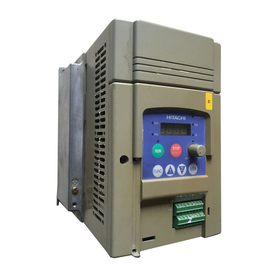
Page 23
Introduction Inverter Specifications Label The Hitachi SJ100 inverters have product labels located on the right side of the housing, as pictured below. Be sure to verify that the specifications on the labels match your power source, motor, and application safety requirements. -
Page 24: Sj100 Inverter Specifications
SJ100 Inverter Specifications Model-specific tables for 200V and 400V class inverters The following tables are specific to SJ100 inverters for the 200V and 400V class model groups. Note that “General Specifications” on page 1–9 groups. Footnotes for all specifications tables follow the table below.
-
Page 25
Note 5: When SLV is selected, please set the carrier frequency higher than 2.1 kHz. Note 6: At the rated voltage when using a Hitachi standard 3-phase, 4-pole motor (when selecting sensorless vector control—SLV). Note 7: The braking torque via capacitive feedback is the average deceleration torque at the shortest deceleration (stopping from 50/60 Hz as indicated). -
Page 26
SJ100 Inverter Specifications, continued… Item SJ100 inverters, CE version 200V models UL version Applicable motor size *2 Rated capacity 230V (kVA) *12 240V Rated input voltage Rated input 1-phase current (A) 3-phase Rated output voltage *3 Rated output current (A) -
Page 27
1–8 SJ100 Inverter Specifications Item SJ100 inverters, CE version 400V models UL version Applicable motor size *2 Rated capacity (460V) kVA Rated input voltage Rated input current (A) Rated output voltage *3 Rated output current (A) Efficiency at 100% rated output (%) -
Page 28: General Specifications
50/60 Hz torque, short time with resistor stop *7 DC braking Weight General Specifications The following table applies to all SJ100 inverters. Item Protective housing *1 Control method Output frequency range *4 Frequency accuracy Frequency setting resolution Volt./Freq. characteristic *5…
-
Page 29
1–10 SJ100 Inverter Specifications Item Input Freq. Operator panel Up and Down keys / Value settings signal setting Potentiometer External signal FWD/ Operator panel Run/Stop (Forward/Reverse run change by command) External signal Forward run/stop, Reverse run/stop Intelligent input terminal Output… -
Page 30
10VDC nominal, 10 mA maximum Alarm relay contacts 250 VAC, 2.5A (R load) max., 0.2A (I load, P.F.=0.4) max. 100 VAC, 10mA min. 30 VDC, 3.0A (R load) max., 0.7A (I load, P.F.=0.4) max. 5 VDC, 100mA min. SJ100 Inverter 4–6. Ratings 1–11… -
Page 31: Derating Curves
Use the following derating curves to help determine the optimal carrier frequency setting for your inverter, and to find the output current derating. Be sure to use the proper curve for your particular SJ100 inverter model number. Legend: SJ100–002NFE/NFU…
-
Page 32
Derating curves, continued… SJ100–007NFE/NFU 100% % of rated output current SJ100–0015NFE/NFU 100% % of rated output current SJ100–022NFE/NFU 100% % of rated output current SJ100 Inverter Carrier frequency Carrier frequency Carrier frequency 1–13… -
Page 33
1–14 SJ100 Inverter Specifications Derating curves, continued… SJ100–037LF/LFU % of rated output current SJ100–055LFU % of rated output current SJ100–075LFU % of rated output current 100% Carrier frequency 100% Carrier frequency 100% Carrier frequency… -
Page 34
Derating curves, continued… SJ100–004HFE/HFU 100% % of rated output current SJ100–007HFE/HFU 100% % of rated output current SJ100–015HFE/HFU 100% % of rated output current SJ100 Inverter Carrier frequency Carrier frequency Carrier frequency 1–15… -
Page 35
1–16 SJ100 Inverter Specifications Derating curves, continued… SJ100–022HFE/HFU % of rated output current SJ100–040HFE/HFU % of rated output current SJ100–055HFE/HFU % of rated output current 100% Carrier frequency 100% Carrier frequency 100% Carrier frequency… -
Page 36
1–17 SJ100 Inverter Derating curves, continued… SJ100–075HFE/HFU 100% % of rated output current Carrier frequency… -
Page 37: Introduction To Variable-Frequency Drives
Introduction to Variable-Frequency Drives The Purpose of Motor Speed Control for Industry Hitachi inverters provide speed control for 3-phase AC induction motors. You connect AC power to the inverter, and connect the inverter to the motor. Many applications benefit from a motor with variable speed, in several ways: •…
-
Page 38
From this it mathematically calculates two vector currents. One vector is related to motor flux current, and the other to motor torque current. The ability to separately control these two vectors is what allows the SJ100 to deliver extraordinary low-speed performance and speed control accuracy. -
Page 39
The Hitachi inverter is a rugged and reliable device. The intention is for the inverter to assume the role of controlling power to the motor during all normal operations. There- fore, this manual instructs you not to switch off power to the inverter while the motor is running (unless it is an emergency stop). -
Page 40
(see page 5–2 “Dynamic Braking” on page 5–5 continuously overhaul the motor for extended periods of time, the SJ100 may not be suitable (contact your Hitachi distributor). The inverter parameters include acceleration and deceleration, which you can set to match the needs of the application. -
Page 41
FWD and REV commands determine the direction before the motion starts. NOTE: The SJ100 can move loads in both directions. However, it is not designed for use in servo-type applications that use a bipolar velocity signal that determines direction. Set speed… -
Page 42: Frequently Asked Questions
Amplifier is a term almost exclusively used to describe drives for servo or stepper motors. Although the SJ100 inverter is a variable speed drive, can I use it in a fixed-speed application? Yes, sometimes an inverter can be used simply as a “soft-start”…
-
Page 43
The greater the number of poles, the slower the top motor speed will be, but it will have higher torque at the base speed. Will I be able to add dynamic (resistive) braking to my Hitachi SJ100 drive after the initial installation? Yes. -
Page 44
Other applications may not need noise suppression, unless you notice electrical interference with the operation of other devices. The SJ100 features a PID loop feature. PID loops are usually associated with chemical processes, heating, or process industries in general. How could the PID… -
Page 45
Inverter Mounting and Installation In This Chapter… — Orientation to Inverter Features — Basic System Description — Step-by-Step Basic — Powerup Test — Using the Front Panel Keypad Installation… page… -
Page 46: Orientation To Inverter Features
Orientation to Inverter Features Unpacking and Inspection Please take a few moments to unpack your new SJ100 inverter and perform these steps: 1. Look for any damage that may have occurred during shipping. 2. Verify the contents of the box include: a.
-
Page 47
Then adhere the remaining trip code label to the area beside the connectors. Be careful not to cover the screw access on models like the one shown. 2–3 SJ100 Inverter Controls for mode and parameter changes… -
Page 48
2–4 Orientation to Inverter Features 3. Third-level access — First, ensure no power source of any kind is connected to the inverter. If power has been connected, wait five minutes after powerdown and verify the Power LED is OFF to proceed. Then locate the recessed retention screw on the left side main front panel (it is along the left hinge area on some models, or behind… -
Page 49: Basic System Description
Input-side This is useful in suppressing harmonics induced on the AC Reactor power supply lines and for improving the power factor. WARNING: Some applications must use an input- side AC reactor to prevent inverter damage. See Warning on next page.
-
Page 50: Step-By-Step Basic Installation
MUST install an input-side AC reactor of 3% (at a voltage drop at rated current) with respect to the supply voltage on the power supply side. Also, where the effects of an indirect lightning strike are possible, install a lightning conductor.
-
Page 51
2–7 SJ100 Inverter Choosing a Mounting Location Step 1: Study the following caution messages associated with mounting the inverter. This is the time when mistakes are most likely to occur that will result in expensive rework, equipment damage, or personal injury. -
Page 52
Remember to remove the top cover (unless the installation is to have a NEMA rating)! 2. Keep any other heat-producing equipment as far away from the inverter as possible. 10 cm (3.94”) minimum 12 cm (4.72”) SJ100 minimum 10 cm (3.94”) minimum Air flow Top cover… -
Page 53
107 (4.21) -005NFE NOTE: Some inverter housings require two mounting screws, while others require four. Be sure to use lock washers or other means to ensure screws do not loosen due to vibration. SJ100 Inverter 67(2.64) 5(0.20) 4(0.16) 80(3.15) 2–9… -
Page 54
2–10 Step-by-Step Basic Installation Dimensional drawings, continued… External Dimensions MODEL SJ 100 -004HFE -004HFU -007NFE -007NFU -011NFE MODEL SJ 100 -007HFE(No fan) -007HFU(No fan) -015HFE -015HFU -022HFE -022HFU 5(0.20) Ground Terminal 98(3.86) 5(0.20) 5(0.20) 110(4.33) 4(0.16) Ground Terminal 98(3.86) 5(0.20) 110(4.33) 4(0.16) -
Page 55
Dimensional drawings, continued… SJ100 -015NFE -015NFU SJ100 -022NFE -022NFU -030HFE -037LFU -040HFE -040HFU Ground Terminal 140(5.51) 128(5.04) 5(0.20) 5(0.20) 140(5.51) 128(5.04) 5(0.20) 5(0.20) 2–11 SJ100 Inverter Ground Terminal… -
Page 56
2–12 Step-by-Step Basic Installation Dimensional drawings, continued… SJ100 -055LFU -055HFE -055HFU -075LFU -075HFE -075HFU 182 (7.17) 160 (6.30) 7 (0.28) NOTE: Model SJ100-075LFU has (2) fans. All other models in this housing have (1) fan. 7 (0.28) Ground Terminal… -
Page 57
HIGH VOLTAGE: Wiring work shall be carried out only by qualified personnel. Oth- erwise, there is a danger of electric shock and/or fire. HIGH VOLTAGE: Implement wiring after checking that the power supply is OFF. Otherwise, you may incur electric shock and/or fire. -
Page 58: Basic System Description
The “Signal Lines” column applies to any wire connecting to the two green 8-position connectors just inside the front panel half-door. Motor Output (kW/HP) Inverter Model SJ100-002NFE/NFU SJ100-004NFE/NFU 0.55 SJ100-005NFE 0.75 SJ100-007NFE/NFU…
-
Page 59
Terminal Dimensions and Torque Specs The terminal screw dimensions for all SJ100 inverters are listed in table below. This information is useful in sizing spade lug or ring lug connectors for wire terminations. CAUTION: Fasten the screws with the specified fastening torque in the table below. -
Page 60
2–16 Step-by-Step Basic Installation Please use the terminal arrangement below corresponding to your inverter model. –002NFE/NFU, –004NFE/NFU, –005NFE –007 to 022NFE/NFU, –037LFU, 004 to 040HFE/HFU –055LFU, –075LFU, 055HFE/HFU, 075HFE/HFU NOTE: An inverter powered by a portable power generator may receive a distorted power waveform, overheating the generator. -
Page 61
Ground fault interrupters in the power input wiring of an inverter are not an absolute protection against electric shock. CAUTION: Be sure to install a fuse in each phase of the main power supply to the inverter. Otherwise, there is the danger of fire. -
Page 62
2–18 Step-by-Step Basic Installation Wire the Inverter Output to Motor Step 7: The process of motor selection is beyond the scope of this manual. However, it must be an AC induction motor with three phases. It should also come with a chassis ground lug. -
Page 63: Powerup Test
• The inverter is connected to a power source and motor. • No additional wiring of inverter connectors or terminals has been done. • The power supply is reliable, and the motor is a known working unit, and the motor nameplate ratings match the inverter ratings.
-
Page 64
Please study the following instructions and messages before proceeding with the powerup test. 1. The power supply must have fusing suitable for the load. Check the fuse size chart presented in Step 5, if necessary. 2. Be sure you have access to a disconnect switch for the drive input power if necessary. -
Page 65: Using The Front Panel Keypad
• Potentiometer — Allows an operator to directly set the motor speed when the potenti- ometer is enabled for output frequency control. • Potentiometer Enable LED — ON when the potentiometer is enabled for value entry. SJ100 Inverter Power LED POWER…
-
Page 66
2–22 Using the Front Panel Keypad • Parameter Display — A 4-digit, 7-segment display for parameters and function codes. • Display Units, Hertz/Amperes — One of these LEDs will be ON to indicate the units associated with the parameter display. •… -
Page 67: Powerup Test
Keypad Navigational Map The SJ100 Series inverter drives have many programmable functions and parameters. Chapter 3 will cover these in detail, but you need to access just a few items to perform the powerup test. The menu structure makes use of function codes and parameter codes to allow programming and monitoring with only a 4-digit display and a few keys and LEDs.
-
Page 68: Using The Front Panel Keypad
2–24 Using the Front Panel Keypad Selecting Functions and Editing Parameters In order to run the motor for the powerup test, this section will show how to: • select the inverter’s maximum output frequency to the motor • select the keypad potentiometer as the source of motor speed command •…
-
Page 69
Run Enable LED above the RUN switch on the keypad will turn ON. This is normal, and does not mean the motor is trying to run. It means that the RUN key is now enabled. DO NOT press the RUN key at this time—finish out the programming exercise first. SJ100 Inverter Display Func./Parameter… -
Page 70
2–26 Using the Front Panel Keypad Configure the Inverter for the Number of Motor Poles- The number of magnetic poles of a motor is determined by the motor’s internal winding arrangement. The specifi- cations label on the motor usually indicates its number of poles. For proper operation, verify the parameter setting matches the motor poles. -
Page 71: Running The Motor
7. Slowly increase the potentiometer setting in clockwise fashion. The motor should start turning when the indicator is in the 9:00 position and beyond. 8. Press the STOP key to stop the motor rotation. SJ100 Inverter HITACHI 5 0.0 STOP RESET 2–23.
-
Page 72
NOTE: Some factory automation devices such as PLCs have alternate Run/Program modes; the device is in either one mode or the other. In the Hitachi inverter, however, Run Mode alternates with Stop Mode, and Program Mode alternates with Monitor Mode. -
Page 73: Configuring Drive Parameters
Configuring Drive Parameters In This Chapter… — Choosing a Programming Device — Using Keypad Devices — “D” Group: Monitoring — “F” Group: Main Profile Parameters — “A” Group: Standard Functions — “B” Group: Fine Tuning Functions — “C” Group: Intelligent Terminal —…
-
Page 74: Choosing A Programming Device
Therefore, it is okay to begin running the motor with a loosely tuned system. By making specific, individual changes and observing their effects, you can achieve a finely tuned system. And, the SJ100 Series inverters have a built-in auto-tuning algorithm to set certain motor parameters.
-
Page 75: Using Keypad Devices
Using Keypad Devices Inverter Front Panel Keypad The SJ100 Series inverter front keypad contains all the elements for both monitoring and programming parameters. The keypad layout is pictured below. All other programming devices for the inverter have a similar key arrangement and function.
-
Page 76
3–4 Using Keypad Devices Keypad Navigational Map You can use the inverter’s front panel keypad to navigate to any parameter or function. The diagram below shows the basic navigational map to access these items. Monitor Mode PRG LED=OFF Display Data 0 0 0.0 FUNC. -
Page 77: Operational Modes
Please refer to “Software Lock Mode” on page 3–28 Control Algorithms The motor control program in the SJ100 inverter has three sinusoidal PWM switch- ing algorithms. The intent is that you select the best algorithm for the motor characteris- tics in your application.
-
Page 78: D» Group: Monitoring Functions
3–6 “D” Group: Monitoring Functions “D” Group: Monitoring Functions Parameter Monitoring Functions You can access important system parameter values with the “D” Group monitoring functions, whether the inverter is in Run Mode or Stop Mode. After selecting the function code number for the parameter you want to monitor, press the Function key once to show the value on the display.
-
Page 79
EEPROM 0.0Hz 0.0A EEPROM 0.0Hz 0.0A Displays total time the inverter has been in RUN mode in hours. 000000H Displays cumulative number of trip events. 3–7 SJ100 Inverter Range Mode Edit Units — Range Mode Edit Units — — —… -
Page 80: F» Group: Main Profile Parameters
3–8 “F” Group: Main Profile Parameters “F” Group: Main Profile Parameters The basic frequency (speed) profile is defined by parameters contained in the “F” Group as shown to the right. The set running frequency is in Hz, but accelera- tion and deceleration are specified in the time duration of the ramp (from zero to maximum frequency, or from maximum frequency to zero).
-
Page 81: A» Group: Standard Functions
A 04 100% Constant torque Maximum Frequency “Configuring the Inverter for Multiple Mode Description Edit ✘ ✘ digital operator ✘ 3–9 SJ100 Inverter A 03 A 04 Base frequency = maximum frequency Defaults –FE –FU –FR Units (CE) (UL) (Jpn) —…
-
Page 82
3–10 “A” Group: Standard Functions “A” Function Func. Name / Code SRW Display A203 Base frequency setting, 2nd motor 2F-BASE 060Hz A_04 Maximum frequency setting F-MAX 060Hz A204 Maximum frequency setting, 2nd motor 2F-MAX 060Hz Analog Input Settings The inverter has the capability to accept an external analog input that can command the output frequency to the motor. -
Page 83
IN F-SAMP Multi-speed and Jog Frequency Setting The SJ100 inverter has the capability to store and output up to 16 preset frequencies to the motor (A_20 to A_35). As in traditional motion terminology, we call this multi-speed profile capability. These preset frequencies are selected by means of digital inputs to the inverter. -
Page 84
3–12 “A” Group: Standard Functions “A” Function Func. Name / Code SRW Display A_20 Multi-speed frequency setting SPD FS 000.0Hz A220 Multi-speed frequency setting, 2nd motor SPD 2FS 000.0Hz A_21 Multi-speed frequency settings A_35 (for both motors) SPD 1 000.0Hz SPD 2 000.0Hz SPD 3… -
Page 85
V/f ratio (shown at right). The boost is applied from zero to 1/2 the base frequency. You set the breakpoint of the boost (point A on the graph) by using SJ100 Inverter Inverter Torque Control Algorithms V/f control, constant torque… -
Page 86
3–14 “A” Group: Standard Functions parameters A_42 and A_43. The manual boost is calculated as an addition to the standard straight V/f line (constant torque curve). NOTE: Manual torque boost is not operational when sensorless vector control is in use. Be aware that running the motor at a low speed for a long time can cause motor overheating. -
Page 87
00… Constant torque 2CONTROL 01… Reduced torque 02… Sensorless vector control A_45 V/f gain setting Sets voltage gain of the inverter from 50 to 100% V-Gain 100% SJ100 Inverter Mode –FE Description Edit (CE) ✘ ✘ ✔ ✔… -
Page 88
3–16 “A” Group: Standard Functions DC Braking Settings The DC braking feature can provide additional stopping torque when compared to a normal deceleration to a stop. DC braking is particularly useful at low speeds when normal decelera- tion torque is minimal. When you enable DC braking, the inverter injects a DC voltage into the motor windings during deceleration below a frequency you can specify (A_52). -
Page 89
A_62 Frequency lower limit Sets a limit on output setting frequency greater than zero Range is 0.5 to 360.0 Hz LIMIT L 000.0Hz 0.0.. setting is disabled >0.1 setting is enabled SJ100 Inverter Output frequency Upper A 61 limit Lower A 62 limit… -
Page 90
3–18 “A” Group: Standard Functions Jump Frequencies – Some motors or machines exhibit resonances at particular speed(s), which can be destructive for prolonged running at those speeds. The inverter has up to three jump frequencies as shown in the graph. The hysteresis around the jump frequencies causes the inverter output to skip around the sensitive frequency values. -
Page 91: Pid Control
01… [O] terminal (voltage in) NOTE: The setting A_73 for the integrator is the integrator’s time constant Ti, not the gain. The integrator gain Ki = 1/Ti. When you set A_73 = 0, the integrator is disabled. SJ100 Inverter for more information. Mode –FE…
-
Page 92
3–20 “A” Group: Standard Functions Automatic Voltage Regulation (AVR) Function The automatic voltage regulation (AVR) feature keeps the inverter output waveform at a relatively constant amplitude during power input fluctuations. This can be useful if the installation is subject to input voltage fluctuations. However, the inverter cannot boost its motor output to a voltage higher than the power input voltage. -
Page 93
Second Acceleration and Deceleration Functions The SJ100 inverter features two-stage acceleration and deceleration ramps. This gives flexibility in the profile shape. You can specify the frequency transition point, the point at which the standard acceleration (F_02) or deceleration (F_03) changes to the second acceleration (A_92) or deceleration (A_93). -
Page 94
3–22 “A” Group: Standard Functions “A” Function Func. Name / Code SRW Display A_95 Acc1 to Acc2 frequency transition point ACC CHFr 000.0Hz A295 Acc1 to Acc2 frequency transition point, 2nd motor 2ACCCHFr 000.0Hz A_96 Dec1 to Dec2 frequency transition point DEC CHFr 000.0Hz A296 Dec1 to Dec2 frequency transition point, 2nd… -
Page 95
00… linear ACCEL LINE 01… S-curve A_98 Deceleration curve Set the characteristic curve of selection Acc1 and Acc2, two options: 00… linear DEC LINE 01… S-curve SJ100 Inverter Output frequency Accel. curve selection Target freq. Acceleration period Mode –FE Description… -
Page 96: B» Group: Fine Tuning Functions
3–24 “B” Group: Fine Tuning Functions “B” Group: Fine Tuning Functions The “B” Group of functions and parameters adjust some of the more subtle but useful aspects of motor control and system configuration. Automatic Restart Mode The restart mode determines how the inverter will resume operation after a fault causes a trip event.
-
Page 97
(if applicable) as shown in the following table. Mode Description Edit ✘ no automatic restart frequency matching ✘ ✘ Torque Constant torque 100% 3–25 SJ100 Inverter Defaults –FE –FU –FR Units (CE) (UL) (Jpn) — sec. sec. B_13 = 01 Reduced… -
Page 98
3–26 “B” Group: Fine Tuning Functions “B” Function Func. Name / Code SRW Display B_12 Level of electronic thermal setting E-THM LVL 03.00A B212 Level of electronic thermal setting, 2nd motor 2E-THMLVL 03.00A B_13 Electronic thermal characteristic E-THM CHAR B213 Electronic thermal characteristic, 2nd motor 2E-THMCHAR… -
Page 99
1% of rated current B_23 Deceleration rate at Sets the deceleration rate when overload restriction inverter detects overload, range is 0.1 to 30.0, resolution is 0.1. OLOAD CONST 01.0 SJ100 Inverter Motor Current Restriction area B 22 Output frequency… -
Page 100
3–28 “B” Group: Fine Tuning Functions Software Lock Mode The software lock function keeps personnel from accidentally changing parameters in the inverter memory. Use B_31 to select from various protection levels. The table below lists all combinations of B_31 option codes and the ON/OFF state of the [SFT] input. -
Page 101
B_31 and output frequency F_01 setting are locked NOTE: To disable parameter editing when using B_31 lock modes 00 and 01, assign the [SFT] function to one of the intelligent input terminals. “Software Lock” on page SJ100 Inverter Mode –FE Description Edit (CE) ✘… -
Page 102
3–30 “B” Group: Fine Tuning Functions Miscellaneous Settings The miscellaneous settings include scaling factors, initialization modes, and others. this section covers some of the most important settings you may need to configure. B_83: Carrier frequency adjustment – The internal switching frequency of the inverter circuitry (also called the chopper frequency). -
Page 103
0.1 to 99.9 /Hz01.0 0.00 B_87 STOP key enable Select whether the STOP key on the keypad is enabled, two STOP-SW option codes: 00… enabled 01… disabled SJ100 Inverter Mode –FE Description Edit (CE) ✔ ✘ ✘ ✘… -
Page 104
3–32 “B” Group: Fine Tuning Functions B_91/B_88: Stop Mode / Restart Mode Configuration – You can configure how the inverter performs a standard stop (each time Run FWD and REV signals turn OFF). Setting B_91 determines whether the inverter will control the deceleration, or whether it will perform a free-run stop (coast to a stop). -
Page 105
“Dynamic Braking” on page 5–5 braking accessories. Mode Description Edit ✘ ✔ terminals (D_05) terminals (D_06) (D_07) ✘ ✘ ✘ OFF during stop for more information on dynamic 3–33 SJ100 Inverter Defaults –FE –FU –FR Units (CE) (UL) (Jpn) — — — —… -
Page 106: C» Group: Intelligent Terminal Functions
Functions and Options –The function codes in the following table let you assign one of nineteen options to any of the six logic inputs for the SJ100 inverters. The functions C_01through C_06 configure the terminals [1] through [6] respectively. The “value” of these particular parameters is not a scalar value, but it is a discrete number that selects one option from many available options.
-
Page 107
(such as [FW]) to show the assigned option. The option codes for C_11 to C_16 determines the active state of the logical input (active high or active low). SJ100 Inverter Mode –FE Description… -
Page 108
3–36 “C” Group: Intelligent Terminal Functions Input Function Summary Table – This table shows all nineteen intelligent input functions at a glance. Detailed descriptions of these functions, related parameters and settings, and example wiring diagrams are in page 4–8. Option Terminal Function Name Code… -
Page 109
F_01 or change the value of F_01 while the inverter is in Run Mode (motor running). If it is necessary to check the value of F_01 during Run Mode, please monitor D_01 instead of F_01. SJ100 Inverter Description On powerup, the inverter will not resume a Run… -
Page 110
3–38 “C” Group: Intelligent Terminal Functions Output Terminal Configuration The inverter provides configuration for logic (discrete) and analog outputs, shown in the table below. “C” Function Func. Name / Code SRW Display C_21 Terminal [11] function OUT-TM 1 C_22 Terminal [12] function OUT-TM 2 C_23 [FM] signal selection MONITOR… -
Page 111
PID error is less than the set threshold for the deviation signal when an alarm signal has occurred and has not been cleared when no alarm has occurred since the last clearing of alarm(s) 3–39 SJ100 Inverter “Using Intelligent… -
Page 112
3–40 “C” Group: Intelligent Terminal Functions Analog Function Summary Table – This table shows all three functions for the analog output [FM] (frequency meter) terminal. Detailed descriptions, related parameters and settings, and example wiring diagrams are in page 4–33. Option Function Name Code Analog Frequency… -
Page 113
C_42 Frequency arrival Sets the frequency arrival setting for acceleration setting threshold for the output frequency during acceleration ARV ACC 000.0Hz SJ100 Inverter Motor current C 41 Overload signal Output frequency C 42 Arrival signal PID Error (PV–SP) deviation threshold… -
Page 114
3–42 “C” Group: Intelligent Terminal Functions “C” Function Func. Name / Code SRW Display C_43 Arrival frequency setting for deceleration ARV DEC 000.0Hz C_44 PID deviation level setting OV PID 003.0% C_81 O input span calibration Scale factor between the ADJ-O C_82 OI input span calibra- tion… -
Page 115: H» Group: Motor Constants Functions
(SLV) control “Restoring Factory Default Settings” on page 4–35. Please read these before trying to auto- Mode Description Edit ✘ ✘ ✘ ✘ ✘ ✘ 3–43 SJ100 Inverter A 44 Output 6–8. “Auto-tuning Defaults –FE –FU –FR Units (CE) (UL) (Jpn) —…
-
Page 116
3–44 “H” Group: Motor Constants Functions “H” Function Func. Name / Code SRW Display H204 Motor poles setting, 2nd motor 2AUXP H_05 Motor speed constant AUX KP H205 Motor speed constant, 2nd motor 2AUXKP H_06 Motor stabilization constant AUX KCD H206 Motor stabilization constant, 2nd motor 2AUXKCD… -
Page 117
H_34 Auto-tuned motor Auto-tuning data (do not edit) constant J (not displayed) H234 Auto-tuned motor Auto-tuning data (do not edit) constant J, 2nd motor (not displayed) SJ100 Inverter Mode –FE Description Edit (CE) ✘ Factory set according to inverter model ✘… -
Page 118
Operations and Monitoring In This Chapter… — Introduction — Connecting to PLCs and Other Devices — Using Intelligent Input Terminals — Using Intelligent Output Terminals — Analog Input Operation — Analog and Digital Monitor Output — Auto-tuning for Sensorless Vector Control —… -
Page 119: Introduction
This chapter shows the parameters and input/output terminals associated with PID loop operation. 6. Multiple motors – A single SJ100 inverter may be used with two or more motors in some types of applications. This chapter shows the electrical connections and inverter parameters involved in multiple-motor applications.
-
Page 120
Otherwise, it may cause injury to personnel. WARNING: If the power supply is cut OFF for a short period of time, the inverter may restart operation after the power supply recovers if the Run command is active. If a restart may pose danger to personnel, so be sure to use a lock-out circuit so that it will not restart after power recovery. -
Page 121: Connecting To Plcs And Other Devices
Connecting to PLCs and Other Devices Connecting to PLCs and Other Devices Hitachi inverters (drives) are useful in many types of applications. During installation, the inverter keypad (or other programming device) will facilitate the initial configura- tion. After installation, the inverter will generally receive its control commands through the control logic connector or serial interface from another controlling device.
-
Page 122: Example Wiring Diagram
N(L3) (T3) Input – circuits – [5] configurable as discrete input or thermistor input Output circuits 4–5 SJ100 Inverter Motor DC reactor (optional) Braking unit (optional) Braking resistor (optional) Alarm contacts, type 1 Form C Open collector outputs Run signal Load Freq.
-
Page 123
4–6 Example Wiring Diagram Specifications of Control and Logic Connections The control logic connectors are located just behind the front panel half-door. The relay contacts are accessible behind the main door. Connector labeling is shown below. Logic inputs Specifications for the logic connection terminals are in the following table: Terminal Name [P24] +24V for logic inputs… -
Page 124
Terminal Listing Use the following tables to locate pages for intelligent input and output material in this chapter. Symbol Code Symbol Code SJ100 Inverter Intelligent Inputs Name Forward Run/Stop Reverse Run/Stop Multi-speed Select, Bit 0 (LSB) Multi-speed Select, Bit 1… -
Page 125: Using Intelligent Input Terminals
The input circuits can use the inverter’s internal (isolated) +24V field supply (P24) to power the inputs. The input circuits are internally connected to the power supply ground. As the diagram shows, you can use a switch (or jumper) to activate an input terminal that has been configured.
-
Page 126
WARNING: If the power is turned ON and the Run command is already active, the motor starts rotation and is dangerous! Before turning power ON, confirm that the Run command is not active. SJ100 Inverter State Description Inverter is in Run Mode, motor runs forward… -
Page 127
4–10 Using Intelligent Input Terminals Multi-Speed Select The inverter can store up to 16 different target frequencies (speeds) that the motor output uses for steady-state run condition. These speeds are acces- sible through programming four of the intelligent terminals as binary-encoded inputs CF1 to CF4 per the table to the right. -
Page 128
A_20 to A_35 in the first procedure 1. a) to 1. d). Input State Example (some CF inputs require input configuration; some are default inputs—see page 3–34): See I/O specs on page 4–6. keys to edit the value. 4–11 SJ100 Inverter Description (MSB) (LSB) keys. -
Page 129
4–12 Using Intelligent Input Terminals Jogging Command The Jog input [JG] is used to command the motor to rotate slowly in small increments for manual operation. The speed is limited to 10 Hz. The frequency for the jogging opera- tion is set by parameter A_38. Jogging does not use an acceleration ramp, so we recom- mend setting the jogging frequency A_38 to 5 Hz or less to prevent tripping. -
Page 130
Do not use the [DB] feature for continuous or high duty cycle as a holding brake. The [DB] input is designed to improve stopping performance. Use a mechanical brake for holding a stop position. SJ100 Inverter [FW, RV] [DB] Output… -
Page 131: Set Second Motor
4–14 Using Intelligent Input Terminals Set Second Motor If you assign the [SET] function to an intelligent input terminal, you can select between two sets of motor parameters. The second parameters store an alternate set of motor characteristics. When the terminal [SET] is turned ON, the inverter will use the second set of parameters to generate the frequency output to the motor.
-
Page 132
Notes: • Function A_94 selects the method for second stage acceleration. It must be set = 00 to select the input terminal method in order for the [2CH] terminal assignment to operate. SJ100 Inverter Output frequency second initial [2CH] [FW],… -
Page 133
4–16 Using Intelligent Input Terminals Free-run Stop When the terminal [FRS] is turned ON, the inverter stops the output and the motor enters the free-run state (coasting). If terminal [FRS] is turned OFF, the output resumes sending power to the motor if the Run command is still active. The free-run stop feature works with other parameters to provide flexibility in stopping and starting motor rotation. -
Page 134: External Trip
When assigned input transitions OFF to ON, inverter latches trip event and displays E12 No trip event for ON to OFF, any recorded trip events remain in history until Reset Example (requires input configuration— see page 3–34): See I/O specs on page 4–6. 4–17 SJ100 Inverter…
-
Page 135: Unattended Start Protection
OFF the Run command per this example (or applying a reset). Then the Run command can turn ON again and start the inverter output. RUN command [FW, RV] [USP] terminal Alarm output terminal Inverter output frequency Inverter power supply Option Terminal Function Name Code Symbol…
-
Page 136: Software Lock
Software lock can include the output frequency by setting B_31. • Software lock by the operator is also possible without the [SFT] terminal being used (B_31). SJ100 Inverter Input Description State The keypad and remote programming devices are prevented from changing parameters The parameters may be edited and stored Example (requires input configuration—see…
-
Page 137: Analog Input Operation
Input Description State Terminal OI is enabled for current input (uses terminal L for power supply return) Terminal O is enabled for voltage input (uses terminal L for power supply return) Example (default input configuration shown for –FU models; –FE and –FR models require input configuration—see page 3–34):…
-
Page 138: Reset Inverter
The Stop/Reset key on the inverter is only operational for a few seconds after inverter powerup when a hand-held remote operator is connected to the inverter. • If the [RS] terminal is turned ON while the motor is running, the motor will be free running (coasting). SJ100 Inverter [RS] approx. 30 ms Alarm…
-
Page 139: Thermistor Thermal Protection
4–22 Using Intelligent Input Terminals Thermistor Thermal Protection Motors that are equipped with a thermistor can be protected from overheating. Input terminal [5] has the unique ability to sense a thermistor resistance. When the resistance value of the thermistor connected to terminal [TH] (5) and [L] is more than 3 k Ohms ±10%, the inverter enters the Trip Mode, turns OFF the output to the motor, and indicates the trip status E35.
-
Page 140
A_04 (maximum frequency setting). • The minimum ON time of [UP] and [DWN] is 50 ms. • This setting modifies the inverter speed from using F_01 output frequency setting as a starting point. SJ100 Inverter Input Description State Accelerates (increases output frequency) motor… -
Page 141: Using Intelligent Output Terminals
Be sure to use a diode across the coil of the relay as shown (reverse-biased) in order to suppress the turn-off spike, or use a solid-state relay. SJ100 Inverter Open collector outputs Logic output common – Load Load…
-
Page 142: Run Signal
NOTE: The example circuit in the table above drives a relay coil. Note the use of a diode to prevent the negative-going turn-off spike generated by the coil from damaging the inverter’s output transistor. SJ100 Inverter [FW], [RV] B 82 Output start freq.
-
Page 143
4–26 Using Intelligent Output Terminals Frequency Arrival Signals The Frequency Arrival group of outputs help coordinate external systems with the current velocity profile of the inverter. As the name implies, output [FA1] turns ON when the output frequency arrives at the standard set frequency (parameter F_01). Output [FA2] relies on programmable accel/ decel thresholds for increased flexibility. -
Page 144
60 ms delay after the frequency thresholds are crossed. Having different accel and decel thresholds provides an asymmetrical output function. However, you can use equal ON and OFF thresholds, if desired. SJ100 Inverter Output 1.5 Hz freq. 0.5 Hz F 01 0.5 Hz… -
Page 145: Overload Advance Notice Signal
4–28 Using Intelligent Output Terminals Overload Advance Notice Signal When the output current exceeds a preset value, the [OL] terminal signal turns ON. The parameter C_41 sets the overload threshold. The overload detection circuit operates during powered motor opera- tion and during regenerative braking. The output circuits use open-collector transistors, and are active low.
-
Page 146: Output Deviation For Pid Control
PID error is less than the set threshold for the deviation signal Example (requires output configuration— see page 3–38): Inverter output terminal circuit H O OI See I/O specs on page 4–6. 4–29 SJ100 Inverter Process variable Setpoint Description FM CM2 12 11 –…
-
Page 147: Alarm Signal
[AL] are different from the contact output terminals [AL0], [AL1], [AL2]. • When the inverter power supply is turned OFF, the alarm signal output is valid as long as the external control circuit has power. •…
-
Page 148
N.O. contact (inverted by C_33 setting) During normal running or power is turned OFF AL0- Contact Power N.O. Open (set Closed C_33=00) Closed 4–31 SJ100 Inverter When an alarm occurs AL0- AL0- State Normal Open Closed Trip Closed Open — Open… -
Page 149: Analog Input Operation
4–32 Analog Input Operation Analog Input Operation The SJ100 inverters provide for analog input to command the inverter frequency output value. The analog input terminal group includes the [L], [OI], [O], and [H] terminals on the control connector, which provide for Voltage [O] or Current [OI] input.
-
Page 150: Analog And Digital Monitor Output
Waveform H O OI C_23 = 00 C_23 = 01 B 81 T = 4 ms 4–33 SJ100 Inverter FM CM2 12 11 Full Scale value 0 – Max. frequency (Hz) 0 – 200% 0 – Max. frequency (Hz) FM CM2 12 11 –…
-
Page 151
4–34 Analog and Digital Monitor Output TIP: When using the analog meter for monitoring, adjust the meter so it has a zero reading when the [FM] output is zero. Then use scale factor B_81 to adjust the [FM] output so the maximum frequency in the inverter corresponds to a full-scale reading on the meter. -
Page 152: Auto-Tuning For Sensorless Vector Control
Auto-tuning for Sensorless Vector Control The SJ100 inverter has a built-in auto-tuning algorithm. Its purpose is to detect and record the motor parameters to use in sensorless vector control. As you may recall from Chapter 3, sensorless vector control (SLV) is the more sophisticated control algorithm the SJ100 inverter can use to deliver higher torque levels at different speeds.
-
Page 153
4–36 Auto-tuning for Sensorless Vector Control Parameter Step Code Name A_82 AVR voltage select Select output voltage for motor A_51 DC braking enable Set = 00 to disable DC braking H_01 Auto-tuning Setting — — — — — — NOTE: During step 11, the motor will make a slight humming sound during the AC and DC excitation (A and B) steps of the auto-tuning process. -
Page 154
Be sure the motor is stopped before you carry out an auto-tuning procedure. Auto-tuning data that is derived while the motor is still running may not be correct. SJ100 Inverter Adjustment Increase the motor speed constant R1 step by step, up to 1.2 times initial value. -
Page 155
4–38 Auto-tuning for Sensorless Vector Control Note 6: Do not interrupt the auto-tuning procedure by removing power or by using the Stop command, unless it is an emergency. If this does occur, initialize the inverter’s parameters to the factory default settings (see Default Settings”… -
Page 156: Pid Loop Operation
∑ Process Variable (Feedback) Analog input scaling A 12 A 11 A 15 A 13 A 14 PID V/I input select 4–39 SJ100 Inverter External Motor Process Sensor Scale factor A 75 F 01 P gain A 72 Frequency setting I gain ∑…
-
Page 157: Configuring The Inverter For Multiple Motors
(fault) events. • Sometimes the slower version of the machine does not have special braking options, but a higher performance version does have braking features. SJ100 U/T1 V/T2…
-
Page 158
Motor capacity Motor poles setting Motor constant R1 Motor constant R2 Motor constant L Motor constant I Motor constant J Motor speed constant Motor stabilization constant 4–41 SJ100 Inverter Parameter Codes 1st motor 2nd motor A_20 A220 F_02 F202 F_03 F203… -
Page 159: Chapter 5: Inverter System Accessories
Inverter System Accessories In This Chapter… — Introduction — Component — Dynamic Braking Descriptions… page…
-
Page 160
Combination: ALI–x2–xxx LPF–xxx R–2–xxx Note: The Hitachi part number series for accesso- ries includes different sizes of each part type, specified by the –x suffix. Hitachi product litera- ture can help match size and rating of your inverter to the proper accessory size. -
Page 161: Component Descriptions
• If the unbalanced factor of the power supply is 3% or higher • If the power supply capacity is at least 10 times greater than the inverter capacity (the power supply capacity is 500 kVA or more) •…
-
Page 162
EMI Filter The EMI filter reduces the conducted noise on the power supply wiring generated by the inverter. Connect the EMI filter to the inverter primary (input side). The FFL100 series filter is required for compliance to the EMC Class A directive (Europe) and C-TICK (Australia). -
Page 163: Dynamic Braking
In many applications, the over-voltage condi- tion serves as a warning signal that we have exceeded the deceleration capabilities of the system. SJ100 inverters have a built-in braking unit, which sends the regenerative energy from the motor during deceleration to the optional braking resistor(s).
-
Page 164
5–6 Dynamic Braking Dynamic Braking Usage Ratio The inverter controls braking via a duty cycle method (percent of the time braking is ON versus total time). Parameter B_90 sets the dynamic braking usage ratio. In the graph to the right, the example shows three uses of dynamic braking in a 100-second period. -
Page 165
SJ100 Dynamic Braking Selection Tables The SJ100 series inverter models have internal braking units. Additional stopping torque is available by adding external resistors. The required braking torque depends on your particular application. Other tables in this section will help you choose the proper resistor. -
Page 166
The example diagram shows a parallel configuration. Please refer to the braking resistor documentation for detailed wiring diagrams. 200V Class JRB Series SJ100 Type & Total Model (Qty) Ohms Number 002NFE/NFU 120–1… -
Page 167
Selecting Braking Resistors for External Braking Units 200V Class Inverters – The following tables specify the braking options for 200V class SJ100 inverters and the braking torque for each option. You can connect a single braking unit to the inverter, or two braking units for additional stopping torque. -
Page 168
Note the column meanings in the tables: • Column “A” = Average braking torque from 60 Hz to 3 Hz. • Column “B” = Average braking torque from 120 Hz to 3 Hz. SJ100 Inverter 200V Models Braking torque Model Number… -
Page 169
400V Class Inverters –The following tables specify the braking options for 400V class SJ100 inverters and the braking torque for each option. You can connect a single braking unit to the inverter, or two braking units for additional braking torque. -
Page 170: Troubleshooting
Troubleshooting and Maintenance In This Chapter… — Troubleshooting… — Monitoring Trip Events, History, & Conditions — Restoring Factory Default Settings — Maintenance and Inspection — Warranty… page…
-
Page 171: Troubleshooting
Please read the following safety messages before troubleshooting or performing mainte- nance on the inverter and motor system. WARNING: Wait at least five (5) minutes after turning OFF the input power supply before performing maintenance or an inspection. Otherwise, there is the danger of electric shock.
-
Page 172: Troubleshooting Tips
[U/T1], [V/T2], and [W/T3]? Are the control terminals [FW] and [RV] wired correctly? Is parameter F_04 properly set? 6–3 SJ100 Inverter Solution • Make sure the parameter setting A_01 is correct. • Make sure the parameter setting A_02 is correct.
-
Page 173
• Check frequency upper limit setting (A_61) • Increase the motor capacity (both inverter and motor). • Fix power supply problem. • Change the output frequency slightly, or use the jump frequency setting to skip the problem frequency. • Verify the V/f settings match motor specifications. -
Page 174: Error Codes
Braking resistor overload E 0 7 Over voltage protection E 0 8 EEPROM error E 0 9 Under-voltage error SJ100 Inverter STOP RESET Fault Trip (setting B_84=00 will clear the trip history but Cause(s) The inverter output was short-circuited, or the motor shaft is locked or has a heavy load.
-
Page 175
6–6 Monitoring Trip Events, History, & Conditions Error Code E 1 0 CT (current transformer) error E 1 1 CPU error E 2 2 E 1 2 External trip E 1 3 E 1 4 Ground fault E 1 5 Input over-voltage E 2 1 Inverter thermal trip… -
Page 176
(n-1) Error exists? E 0 3 FUNC. (n-2) Error exists? E 0 5 No error FUNC. 6–7 SJ100 Inverter and E ) using the FUNC. Trip History history Previous _ _ _ error #1 FUNC. history Previous _ _ _ error #2 FUNC. -
Page 177: Restoring Factory Default Settings
6–8 Restoring Factory Default Settings Restoring Factory Default Settings You can restore all inverter parameters to the original factory (default) settings for the intended country of use. After initializing the inverter, use the powerup test in Chapter 2 to get the motor running again. To initialize the inverter, follow the steps below. Use the FUNC.
-
Page 178: Maintenance And Inspection
✔ Visual ✔ Visual ✔ Visual ✔ Visual 6–11. 6–9 SJ100 Inverter Criteria Ambient temperature between -10 to 40°C, non-condensing Stable environment for electronic controls 200V class: 200 to 240V 50/60 Hz 400V class: 380 to 460V 50/60 Hz 5 Meg.
-
Page 179: Megger Test
I/O, analog terminals, etc. Doing so could cause damage to the inverter. CAUTION: Never test the withstand voltage (HIPOT) on the inverter. The inverter has a surge protector between the main circuit terminals above and the chassis ground. Add test jumper wire Disconnect motor wires SJ100 Earth – Motor Megger, 500VDC…
-
Page 180: Spare Parts
Quantity Symbol Used Spare Variable-frequency Drive Internal Inverter DC Bus – Capacitor Life Curve Operation for 12 hours/day 6–11 SJ100 Inverter Notes 022NF, 030HF, 037LF, 015HF to 075HF • Front case • Key cover • Case • Bottom cover Motor…
-
Page 181
6–12 Maintenance and Inspection General Inverter Electrical Measurements The following table specifies how to measure key system electrical parameters. The diagrams on the next page show inverter-motor systems and the location of measurement points for these parameters. Circuit location Parameter of measurement Supply voltage –… -
Page 182
The voltage to be measured is the funda- mental wave effective voltage. The power to be measured is the total effective power. Single-phase Measurement Diagram Three-phase Measurement Diagram SJ100 Inverter Inverter Inverter 6–13… -
Page 183
6–14 Maintenance and Inspection Inverter Output Voltage Measurement Techniques Taking voltage measurements around drives equipment requires the right equipment and a safe approach. You are working with high voltages and high-frequency switching waveforms that are not pure sinusoids. Digital voltmeters will not usually produce reliable readings for these waveforms. -
Page 184
≅ 0 Ω ≅ ∞ Ω ≅ ∞ Ω ≅ 0 Ω ≅ ∞ Ω ≅ 0 Ω ≅ ∞ Ω ≅ 0 Ω 6–15 SJ100 Inverter Measured Part Value – ≅ 0 Ω [–] ≅ ∞ Ω [–] ≅ 0 Ω… -
Page 185: Warranty
(2) years from the date of manufacture (“DATE” on product nameplate), or one (1) year from the date of installation, whichever occurs first. The warranty shall cover the repair or replacement, at Hitachi’s sole discretion, of ONLY the inverter that was installed.
-
Page 186: Appendix A: Glossary And Bibliography
Glossary and Bibliography In This Appendix… — Glossary — Bibliography page…
-
Page 187
Auto-tuning is a common feature of process controllers with PID loops. Hitachi inverters feature auto tuning to determine motor parameters for optimal commutation. Auto-tuning is avail- able as a special command from a digital operator panel. See also Digital Operator Panel. -
Page 188
Digital Operator Panel For Hitachi inverters, “digital operator panel” (DOP) refers first to the operator keypad on the front panel of the inverter. It also includes hand-held remote keypads, which connect to the inverter via a cable. -
Page 189
A device that electronically changes DC to AC current through an alternating process of switching the input to the output, inverted and non-inverted. A variable speed drive such as the Hitachi SJ100 is also called an inverter, since it contains three inverter circuits to generate 3-phase output to the motor. -
Page 190
The ability of a motor drive to store preset discrete speed levels for the motor, and control motor speed according to the currently selected speed preset. The Hitachi inverters have 16 preset speeds. Motor Load In motor terminology, motor load consists of the inertia of the physical mass that is moved by the motor and the related friction from guiding mechanisms. -
Page 191
A–6 Glossary Reactance Rectifier Regenerative Braking Regulation Reverse Torque Rotor Saturation Voltage Sensorless Vector Control Setpoint (SP) Pulse-width modulation: A type of AC adjustable frequency drive that accomplishes frequency and voltage control at the output section (inverter) of the drive. The drive output voltage waveform is at a constant amplitude, and by “chopping”… -
Page 192
Hot varies sinusoidally above and below Neutral. This power source is named Single Phase to differentiate it from three-phase power sources. Some Hitachi inverters can accept single phase input power, but they all output three-phase power to the motor. See also Three-phase. -
Page 193
The saturation voltage has been decreasing, resulting in less heat dissipation. Hitachi inverters use state-of-the- art semiconductors to provide high performance and reliability in a compact package. See also IGBT and Saturation Voltage. -
Page 194: Appendix B: Drive Parameter Settings Tables
Drive Parameter Settings Tables In This Appendix… — Introduction — Parameter Settings for Keypad Entry… page…
-
Page 195
Parameter Settings for Keypad Entry SJ100 series inverters provide many functions and parameters that can be configured by the user. We recommend that you record all parameters that have been edited, in order to help in troubleshooting or recovery from a loss of parameter data. -
Page 196: Standard Functions
Multi-speed 5 setting A_26 Multi-speed 6 setting A_27 Multi-speed 7 setting A_28 Multi-speed 8 setting A_29 Multi-speed 9 setting A_30 Multi-speed 10 setting A_31 Multi-speed 11 setting SJ100 Inverter Default Setting –FR (Europe) (USA) (Japan) 50.0 60.0 60.0 50.0 60.0 60.0 50.0 60.0…
-
Page 197
B–4 Parameter Settings for Keypad Entry “A” Group Parameters Func. Name Code A_32 Multi-speed 12 setting A_33 Multi-speed 13 setting A_34 Multi-speed 14 setting A_35 Multi-speed 15 setting A_38 Jog frequency setting A_39 Jog stop mode A_41 Torque boost method selection A241 Torque boost method selection, 2nd motor… -
Page 198
2nd motor A_96 Dec1 to Dec2 frequency transi- tion point A296 Dec1 to Dec2 frequency transi- tion point, 2nd motor A_97 Acceleration curve selection A_98 Deceleration curve selection SJ100 Inverter Default Setting –FR (Europe) (USA) (Japan) 1.00 1.00 1.00 230/400 230/460 200/400 15.0… -
Page 199
B–6 Parameter Settings for Keypad Entry Fine Tuning Functions “B” Group Parameters Func. Name Code B_01 Selection of automatic restart mode B_02 Allowable under-voltage power failure time B_03 Retry wait time before motor restart B_12 Level of electronic thermal setting B212 Level of electronic thermal setting, 2nd motor… -
Page 200
“B” Group Parameters Func. Name Code B_89 Data select for digital op. OPE-J B_90 Dynamic braking usage ratio B_91 Stop mode selection B_92 Cooling fan control SJ100 Inverter Default Setting –FR (Europe) (USA) (Japan) B–7 User Setting… -
Page 201
B–8 Parameter Settings for Keypad Entry Intelligent Terminal Functions “C” Group Parameters Func. Name Code C_01 Terminal [1] function C_02 Terminal [2] function C_03 Terminal [3] function C_04 Terminal [4] function C_05 Terminal [5] function C_06 Terminal [6] function C_11 Terminal [1] active state C_12 Terminal [2] active state… -
Page 202
H206 Motor stabilization constant, 2nd motor H_20 Motor constant R1 H220 Motor constant R1, 2nd motor H_21 Motor constant R2 H221 Motor constant R2, 2nd motor SJ100 Inverter Default Setting –FR (Europe) (USA) (Japan) 0000 0000 0000 — — —… -
Page 203: Parameter Settings For Keypad Entry
B–10 Parameter Settings for Keypad Entry “H” Group Parameters Func. Name Code H_22 Motor constant L H222 Motor constant L, 2nd motor H_23 Motor constant Io H223 Motor constant Io, 2nd motor H_24 Motor Constant J H224 Motor constant J, 2nd motor H_30 Auto-tuned motor constant R1 H230…
-
Page 204: Appendix C: Ce-Emc Installation Guidelines
CE–EMC Installation Guidelines In This Appendix… — CE–EMC Installation Guidelines — Hitachi EMC Recommendations page…
-
Page 205: Ce-Emc Installation Guidelines
CE–EMC Installation Guidelines CE–EMC Installation Guidelines You are required to satisfy the EMC directive (89/336/EEC) when using an SJ100 inverter in an EU country. To satisfy the EMC directive and to comply with standard, follow the guidelines in this section.
-
Page 206
• Ground the filter with a conductor of at least 10 mm • Connect a second grounding conductor, using a separate grounding terminal parallel to the protective conductor. (The cross section of each single protective conductor terminal must be sized for the required nominal load.) C–3 SJ100 Inverter cross-sectional area. -
Page 207
C–4 CE–EMC Installation Guidelines SJ100 inverter with footprint-type filter… -
Page 208
C–5 SJ100 Inverter SJ100 inverter with book-type filter… -
Page 209: Hitachi Emc Recommendations
Failure to observe this precaution could result in bodily injury. Use the following checklist to ensure the inverter is within proper operating ranges and conditions. 1. The power supply to SJ100 inverters must meet these specifications: • Voltage fluctuation ±10% or less • Voltage imbalance ±3% or less •…
-
Page 210: Index
Index A Group functions 3–9 AC reactors 5–3 Acceleration 1–22, 3–8 characteristic curves 3–23 second function 3–21 two-stage 4–15 Access levels 3–5, 3–28, 4–19 Access to terminals 2–2 Accessories 5–2 Alarm signal 4–30 Algorithms 3–43 Algorithms, torque control 3–5 Ambient temperature 2–8, A–2 Analog input settings 3–10…
-
Page 211
Index–2 D Group parameters 3–6 DC braking 3–16, 4–12, 4–13, DC link choke 5–4 Deadband A–3 Deceleration 1–22, 3–8, characteristic curves second function 3–21 two-stage 4–15 Default parameter values Default settings restoring 6–8 Derating curves 1–12 Derivative gain 3–19 Digital operator 2–21, 3–3 Digital operator panel A–3… -
Page 212
Multi-speed operation 4–10, Multi-speed profiles Multi-speed settings Nameplate 1–4 Navigational map 2–23, trip events A–5 NEMA A–5 NEMA rating Noise filters 5–2 AC reactor Index–3 SJ100 Inverter 3–23 4–6 3–8 6–9 1–4 1–4 3–4 3–6 2–28 3–43 4–35 2–26 2–18 2–9 2–7… -
Page 213
Index–4 Open-collector outputs 4–24, Operational modes 3–5 Operator interfaces 1–3 Optional components 2–5 Options 1–2 Output adjustment parameters Output circuits 4–24 Output deviation for PID control Output frequency 3–8 Output overload 3–27 Output terminals 2–18 Overload advance notice signal Overload restriction 3–27 Parameter editing 2–21, Parameter settings tables… -
Page 214
6–5 external 4–17 monitoring 6–5 Trip history 6–7 Trip mode 4–21 Troubleshooting tips 6–3 Two-stage accel/decel 4–15 SJ100 Inverter UL instructions Unattended start protection Unpacking 2–2 Up/Down functions V/f control 3–13 Variable torque 3–13 Variable-frequency drives introduction 1–18 Velocity profile 1–22…
Устройство:
Hitachi SJ100
Размер: 5,27 MB
Добавлено: 2014-09-25 12:13:08
Количество страниц: 214
Печатать инструкцию
Скачать
Как пользоваться?
Наша цель — обеспечить Вам самый быстрый доступ к руководству по эксплуатации устройства Hitachi SJ100. Пользуясь просмотром онлайн Вы можете быстро просмотреть содержание и перейти на страницу, на которой найдете решение своей проблемы с Hitachi SJ100.
Для Вашего удобства
Если просмотр руководства Hitachi SJ100 непосредственно на этой странице для Вас неудобен, Вы можете воспользоваться двумя возможными решениями:
- Полноэкранный просмотр -, Чтобы удобно просматривать инструкцию (без скачивания на компьютер) Вы можете использовать режим полноэкранного просмотра. Чтобы запустить просмотр инструкции Hitachi SJ100 на полном экране, используйте кнопку Полный экран.
- Скачивание на компьютер — Вы можете также скачать инструкцию Hitachi SJ100 на свой компьютер и сохранить ее в своем архиве. Если ты все же не хотите занимать место на своем устройстве, Вы всегда можете скачать ее из ManualsBase.
Hitachi SJ100 Руководство по эксплуатации
Печатная версия
Многие предпочитают читать документы не на экране, а в печатной версии. Опция распечатки инструкции также предусмотрена и Вы можете воспользоваться ею нажав на ссылку, находящуюся выше — Печатать инструкцию. Вам не обязательно печатать всю инструкцию Hitachi SJ100 а только некоторые страницы. Берегите бумагу.
Резюме
Ниже Вы найдете заявки которые находятся на очередных страницах инструкции для Hitachi SJ100. Если Вы хотите быстро просмотреть содержимое страниц, которые находятся на очередных страницах инструкции, Вы воспользоваться ими.
Содержание
- Руководство по эксплуатации Hitachi SJ100
- Руководство по эксплуатации для устройства Hitachi SJ100
- Как пользоваться?
- Преобразователи частоты Hitachi — инструкция функций
- Немного истории
- Основные особенности частотника Hitachi
- Преобразователи частоты Hitachi NE-S1
- Преобразователи частоты Hitachi L100
- Преобразователь частоты Hitachi WJ200
- Преобразователь частоты Hitachi X200
- Частотные преобразователи Hitachi SJ200
- О программируемых функциях Hitachi sj 200
- О торможении двигателя
Руководство по эксплуатации Hitachi SJ100
Руководство по эксплуатации для устройства Hitachi SJ100
Устройство: Hitachi SJ100
Размер: 5,27 MB
Добавлено: 2014-09-25 12:13:08
Количество страниц: 214
Печатать инструкцию
Как пользоваться?
Наша цель — обеспечить Вам самый быстрый доступ к руководству по эксплуатации устройства Hitachi SJ100 . Пользуясь просмотром онлайн Вы можете быстро просмотреть содержание и перейти на страницу, на которой найдете решение своей проблемы с Hitachi SJ100 .
Для Вашего удобства
Если просмотр руководства Hitachi SJ100 непосредственно на этой странице для Вас неудобен, Вы можете воспользоваться двумя возможными решениями:
- Полноэкранный просмотр -, Чтобы удобно просматривать инструкцию (без скачивания на компьютер) Вы можете использовать режим полноэкранного просмотра. Чтобы запустить просмотр инструкции Hitachi SJ100 на полном экране, используйте кнопку Полный экран .
- Скачивание на компьютер — Вы можете также скачать инструкцию Hitachi SJ100 на свой компьютер и сохранить ее в своем архиве. Если ты все же не хотите занимать место на своем устройстве, Вы всегда можете скачать ее из ManualsBase.
Печатная версия
Многие предпочитают читать документы не на экране, а в печатной версии. Опция распечатки инструкции также предусмотрена и Вы можете воспользоваться ею нажав на ссылку, находящуюся выше — Печатать инструкцию . Вам не обязательно печатать всю инструкцию Hitachi SJ100 а только некоторые страницы. Берегите бумагу.
Резюме
Ниже Вы найдете заявки которые находятся на очередных страницах инструкции для Hitachi SJ100 . Если Вы хотите быстро просмотреть содержимое страниц, которые находятся на очередных страницах инструкции, Вы воспользоваться ими.
Источник
Преобразователи частоты Hitachi — инструкция функций

Фирма Hitachi изготавливает частотные преобразователи с 1970-х годов. Это одна из лидеров мира в этой отрасли.
Преобразователи частоты Hitachi сконструированы таким образом, что учтены возможности электрических линий и стандартов многих стран. Это документы CE, UL.
В устройстве Hitachi применяются новые компоненты и блоки (ISPM), векторное управление без сенсоров и знаменитые возможности по соединению в линии промышленности.Высокая устойчивость оборудования к отказам, хорошая защищенность электромотора обуславливается составляющими высокого качества своего производства.
На российском рынке преобразователи частоты Hitachi занимают прочную позицию, так как это качественные и надёжные приборы.

Преобразователи частоты Хитачи используются повсеместно там, где есть необходимость регулирования частоты оборотов электрических двигателей. По своей сути — эти устройства универсальны благодаря возможности полноценногопрограммирования работы.
Частотные преобразователи Hitachi имеют большие возможности векторного контроля при настраивании и создании программного обеспечения. Они также обеспечивают простоту программирования, возможна установка модулей со многими опциями, дают возможность выше расширять места использования. Преобразователи частоты Hitachi имеют такие преимущества: эффективность расхода энергии, удобный и приятный встроенный интерфейс и вход датчика тепловой защиты, подключение к линии сервисов мира и частотной характеристике.

Японские инженеры учитывают особенности российского пользователя и все частотники Hitachi попадающие на российский рынок способны выдерживать, практически любые нагрузки. Быть может, именно учитывая российские нагрузки и манеру пользования, японцы и наделили свои преобразователи частоты возможностью выдерживать кратковременные перегрузки в 200%. Но это не означает, что приборы смогут штатно работать под такой перегрузкой. Рассчитывать нагрузку нужно грамотно, с запасом в 20%. Тогда любой частотный преобразователь Hitachi будет работать без поломок, свыше заявленных в паспорте сроков.
Преобразователи частоты Hitachi можно встретить практически на любом производстве и в любом цеху. Также они применяются при строительстве насосных станций, систем вентиляции больших зданий и жилых домов. Применяются как в промышленности всех направлений, так и в сельскохозяйственной деятельности.
Немного истории
Частотные преобразователи и промышленная автоматизация производиться в Японии с 1979 года. Именно тогда Хитачи начала выпускать первые преобразователи частоты и системные реле. Наработки тех лет легли в основу производства современных преобразователей частоты и блоков автоматического управления производством.
Сегодня, все приборы компании разрабатываются с учётом возможностей и потребностей электросетей региона, куда намерены направить на реализацию партию частотников. Также, все приборы Хитачи соответствуют стандартам как страны назначения, так и международным CE и UL.

Авторитет среди пользователей преобразователи частоты из Японии получают и потому что, компания Хитачи стремится использовать для сборки только собственные компоненты. Таким образом, инженеры Хитачи отвечают за каждый узел и каждую микросхему в собранном ими приборе, что существенно увеличивает надёжность готового продукта.
Таким образом, удаётся добиться высокого уровня отказоустойчивости и надёжности прибора, а также защитить двигатель. Частотный преобразователь Hitachi – верное решение профессионалов.
Hitachi применяет в своих преобразователях частоты инновационные компоненты, такие как:
- ISPM-модуль.
- БВУ (безсенсорное векторное управление).
- Расширения интеграции в автоматизированные сети.
- Встроенные PID контроллер.
Все эти особенности делают любой преобразователь Hitachi универсальным устройством, готовым к применению в любом агрегате.
Сетевое расширение прибора обеспечивает простоту программирования памяти и задачу режима работы, а интеллектуальная панель управления обеспечивает простоту ручного ввода данных в память. Интеллектуальная панель присутствует во всех моделях преобразователей частоты Хитачи.
Основные особенности частотника Hitachi
Все линейки частотников Хитачи обладают весьма расширенными возможностями по настройке и программированию режимов работы. Также, преобразователи имеют возможность подключения дополнительного оборудования, что существенно расширяет сферу их применения в промышленности.
Также, к основным преимуществам ПЧ Hitachi относят:
- Экономичность.
- Энергетическая эффективность.
- Удобный интерфейс.
- Лёгкая конструкция.
- Усовершенствованный корпус и система охлаждения позволяю устанавливать большое количество частотников рядом друг с другом.
- Доступность сервиса по всему миру.
Преобразователи частоты Hitachi NE-S1
Частотник Hitachi NE-S1 является универсальным среди многих подобных устройств.

Свойство делать программы обеспечивает преобразователь для широкого применения. Hitachi NE-S1 является экономным устройством для изменения частоты большого интервала мощности, до 4 киловатт.
Частотный преобразователь Hitachi NE-S1 сконструирован для потребностей изготовителей и систем. Он имеет очень компактный дизайн, удобство работы, и дает возможность производить наладку прямо из упаковки.
Этот вид частотника небольшого размера, с большими функциями: подходит для трехпроводного канала Старт – Стоп и для Sink или Sourse, встроенный pid — векторное управление функции, пусковой момент, инвертор, временная часть и логика, энегросбережение, встроенный интерфейс. Частотный преобразователь стандартизирован, может соединяться посредством интерфейс rs422. Можно установить экран для работника впереди приборов для видимости опций и настраивания.
Преобразователи частоты Hitachi L100
Собратом ПС Hitachi sj 200 является модель L100. По своей сути, это такой же преобразователь, который обладает теми же свойствами, той же надёжностью, но более компактный. Работает прибор в диапазоне мощностей от 370 ватт, до 7,5 киловатт. Также представлен в двух классах:
- 200 В (однофазные и трёхфазные).
- 400 В (только трёхфазные).

Его конструкция также позволяет монтировать частотники близко друг к другу, не опасаясь перегрева.
К основным особенностям преобразователя частоты Hiachi L100 относят:
- Встроенный PID контроллер.
- Интерфейс rs422.
- Встроенный интерфейс сетевого протокола.
- Подстройка напряжения (автомат).
- EMC фильтр Class B.
- СЕ стандарт (полное соответствие).

Такие конструкции имеют мощность до 130 киловатт. Это партия со многими функциями технологии для управляемости приводов с нагрузочными опциями токов разной переменности.

При разработке Hitachi l100 надо было достигнуть хорошей экономики, чтобы можно было применять на контролирование частоты и потенциала. В итоге разработали маленькие частотники.
В небольшом объеме частотника Hitachi l100 собрано много обычных опций: современный источник напряжения с контроллером, который может получать оптимизированные характеристики, энергетический вид экономики, встроенный pid — управляемость на регулировку данных работы, обеспечивает простоту программирования датчика тепловой защиты электродвигателя. Это еще не все возможности преобразователя частоты Hitachi l100.

Такие возможности и пусковой момент дают Hitachi l100 право быть лучшим в типах, которые должны быть на высоте надежности: кондиционеры воздуха, вентиляторы, обогреватели, насосы, техпроцессы, которые связаны с расходным управлением. инвертор также имеет потенциометр, вход датчика тепловой защиты, частотной характеристике, панель управления обеспечивает простоту и новые панели, удобство управления. Это дает виды использования соединения в промышленности.
Преобразователь частоты Hitachi WJ200
Преобразователи этой серии придуманы, чтобы обеспечить лучшую загруженность.

Частотный преобразователь Hitachi WJ200 оснащен современным способом управляемости, применяется электроприводных типах до 15 киловатт.
Из серии WJ200 производится на интервал переменного тока от 200 до 400 вольт. Исполнен он с трехфазным и 1-фазным выходом.
Преобразователь частоты Hitachi WJ200 обеспечен опцией интеграции автотюнинга, автонастройки для создания современной управляемости. Это дает реализацию большого толчка пуска до 200%, применять во многих местах.
У такого частотника есть функции, они обеспечивают векторное управление. Ее можно сравнить с ПЛК. Также имеется корпус торможения динамики. Это дает возможность подсоединения сопротивлений тормоза прямо к частотнику. Можно работать с электромоторами более высокими мощности, это связано с видом частотника. Внедрены инновационные функции, интеллектуальная панель, работоспособные в изменении перепадов потенциала и тока. Обеспечена возможность контролирования оси электромотора, его положения, остановка безопасного типа.
Охлаждение воздуха оптимизировано и дает возможность поставить частотники рядом, не рискуя превысить температуру инвертор векторного контроля нагрева (если окружающая среда нормальной температуры). Частотный преобразователь Hitachi WJ200 применяется с моторами различного типа, полностью стандартизирован.
Преобразователь частоты Hitachi X200
Частотный преобразователь Hitachi X200 является конструкцией для экономных приводов моторов до 7,5 киловатт. Они используются для машин, вентиляторов и помп. Частотник оборудован фильтром помех, стандартизирован.

В нем можно совмещать сети промышленности CanOpen и Profibus. Конструкция снабжена энергосберегающей функцией, возможно подключение к Modbus RTU и интерфейс rs422. Такие устройства устанавливаются вплотную по бокам.
Частотные преобразователи Hitachi SJ200
Особо примечательной моделью в линии ПЧ Хитачи является Hitachi sj 200. Рассмотрим несколько особенностей этого частотника. Конструкция имеет компактный фильтр большой мощности. Он сохраняет объем, который предусмотрен для управляемости моторов. Частотник является сильным устройством, обладает оптимизацией ISPM. Лучшие параметры эксплуатации и схема дают большое усилие вращения в трудных эксплуатационных условиях.

Частотный преобразователь Hitachi SJ200 инвертор по своим размерам маленький корпус для своего класса, идеален для типографий, целлюлозной, легкой отрасли, для лифтовых и подъемных механизмов и металлообработки. Мощность его достигает до 7,5 киловатт, усилие пуска обеспечено до 200% от нормального. Имеет регулировку по PID, напряжение с автоматической регулировкой, есть интеллектуальная панель.
Также, компактный преобразователь частоты Hitachi SJ200 имеет в своем оборудовании тормозной блок, фильтр магнитных помех, потенциометр, двигатель с термистором, соответствует международным стандартам, панель управления обеспечивает простоту использования. Имеется векторная бессенсорная регулировка, сбережение электроэнергии в автоматическом режиме.
Частотники Хитачи очень надежные механизмы с функциональными приводами для заводских условий, где нуждаются в регулировке оборотов электромоторов. Нет такой отрасли производства, где бы нельзя было использовать преобразователи тока Хитачи.
Инверторы Hitachi sj 200 объединяют в себе две группы преобразователей частоты:
Оба этих класса преобразователей частоты могут применяться в сетях как США, так и Европы. Несмотря на то, что входящие параметры напряжения разнятся, частотник Hitachi sj 200 может работать как с одними параметрами, так и с другими.

Входящее питание для инвертора класса 200 В должно быть в пределах 200 – 240 вольт, а напряжение для класса 400 В, варьируется в пределах 380 – 480 вольт. Напряжение переменное. Отдельные модели Hitachi sj 200 допускают работу, как в однофазной сети, так и в трёхфазной. Но все представитель класса 400 В работают в трёхфазных сетях.
Если на предприятии не имеется трёхфазного питания, то своё внимание лучше обратить на преобразователь частоты Hitachi sj 200 с мощностью до 2,2 кВт. Он гарантировано сможет работать от однофазной сети, при этом выдавать на выходе полноценную мощность электрического двигателя.
Для Hitachi sj 200 очень важно, чтобы прибор был заземлён. Заземлению подлежит и корпус самого электрического двигателя, который работает от ПЧ. Это нужно как для безопасности пользователя, так и для защиты самого прибора. Электронные компоненты частотника могут выйти из строя из-за скопившегося на корпусе прибора статического напряжения.
При подключении ПЧ Hitachi sj 200 используются стандартные обозначения. Если имеем дело с однофазным преобразователем частоты, то обозначения соответственно фаза и ноль. Если имеем дело с трёхфазным, то фазы обозначаются по очереди: фаза 1, фаза 2, фаза 3 и ноль. Очерёдность фаз соответствует входящим клеммам электрического двигателя (Т1, Т2, Т3).
При подключении электрического двигателя и при пробном пуске нужно убедиться, что вал крутится в нужном направлении во избежание поломки агрегата и травм персонала.
Для изменения направления вращения вала нет необходимости физически переподключать фазы. Это можно сделать и через интерфейс управления, просто введя нужную настройку. Преобразователь Hitachi позволяет делать такую настойку.
О программируемых функциях Hitachi sj 200
Удобство управления электрическим двигателем обеспечивает система программирования преобразователя частоты.
Преобразователь частоты Hitachi sj 200 управляется центральным микропроцессором по программе, которая занесена в EEPROM (ППЗУ). В памяти прибора хранятся заданные пользователем параметры, и по ним осуществляется управление работой электрического двигателя.
Hitachi sj 200 оснащён и дополнительным устройством считывания и записи информации. Эта опция позволяет упростить работу сборщиков систем управления. Эта возможность позволяет точно скопировать настройки одного инвертора в другой.

О торможении двигателя
Разумеется, не только движение важно в современном производстве. Также нередко приходится использовать и функцию торможения двигателя, когда вал на больших оборотах продолжает вращаться по инерции. Система торможения с использованием стопорных устройств и тормозных колодок не применяется уже очень давно.
Hitachi sj 200 имеет в себе и алгоритм торможения двигателя.
Общее понятие торможения в данном случае включает в сети воздействие магнитной силы, в противоположном направлении движения вала. То есть преобразователь частоты меняет кратковременно параметры штатной работы и стремится погасить энергию движения вала двигателя.
Тут важно соблюдать меру, так как противодействие магнитной индукции вызывает сильный нагрев обмоток двигателя. Что может привести к перегоранию обмоток. Но за это тоже отвечает сам преобразователь частоты. Он может, как интеллектуально вычислять возможный перегрев и бороться с ним, а может и с помощью датчика тепловой защиты двигателя определять перегрев и не допустить поломки двигателя.
Источник
-
Страница 1
HIT A CHI SJ100 Series In ver ter Instruction Man ual • Single-phase Input 200V Class • Three-phase Input 200V Class • Three-phase Input 400V Class After r eading this manual, keep it handy f or futur e r eference. Hitachi Industrial Equipment Systems Co., Ltd. Manual Number : NB585XF December 2003 Co v er[…]
-
Страница 2
SJ100 Inverter i Saf ety Messa ges For the best results with the SJ100 Series in v erter , carefully read this manual and all of the warning labels attached to the in v erter before installing and operating it, and follo w the instructions exactly . K eep th is manual handy for quick reference. Definitions and Symbols A safety instruction (message)[…]
-
Страница 3
ii General Precautions — Read These Fir st! W ARNING: This equipment should be installed, adjusted, and serviced by qualified electrical maintenance personnel familiar w ith the construction and operation of the equipment and the hazards in volv ed. Failure to observe this precaution could result in bodily injury . W ARNING: The user is responsible[…]
-
Страница 4
SJ100 Inverter iii W ARNING: Rotating shafts and above -ground electr ical potentials can be hazardous. Therefore, it is strongly recommended that all electrical work conform to the National Electrical Codes and local regulations. Inst allation , alignment and maintenance should be performed only by qualified p ersonnel. Factory-recommended test pr[…]
-
Страница 5
iv Inde x to W arnings and Cautions in This Manual Installation — Cautions fo r Mounting Pr ocedures Wiring — W arnings for Electrical Practices and Wire Specifications CA UTION: The in verter is shipped w ith a plastic cover o ver the top v ent grill. REMO VE this cover after the installation is complete. Operation with this cov e r in place will […]
-
Страница 6
SJ100 Inverter v Wiring — Cautions f or Electrical Practices W ARNING: “Suitable for use on a circui t capable of deli vering not more than 5,000 rms symmetrical amperes, 480 V maximum. ” For models with suf fix H. …. 2–13 HIGH V OL T A GE: Be sure to ground the unit. Otherwise, there is a danger of electric shock and/or f ire. …. 2–13 […]
-
Страница 7
vi P owerup T est Caution Messages CA UTION: Remarks for using ground fault interrupter break ers in the main po wer supply: Adjustable freque nc y in verters with CE-f ilters (RFI- filter) and shielded (screened) motor cables ha ve a higher leakage current to ward Earth GND. Especially at the moment of switching ON this can cause an inadvertent tr[…]
-
Страница 8
SJ100 Inverter vii W arnings for Configuring Drive P arameters Cautions f or Configuring Drive P arameters W arnings for Operations and Monitoring W ARNING: When parameter B_12, lev e l of electronic thermal setting, is set to de vice FLA rating (Full Load Ampere nameplate rating), the device provides solid state motor o verload pr otection at 115%[…]
-
Страница 9
viii Cautions f or Operations and Monitoring W ARNING: Be sure not to touch the insi de of the energized in verter or to put any conducti ve object into it. Othe rwise, there is a danger of electric shock and/or fire. ……. 4–3 W ARNING: If power is turned ON when the Run command is already acti ve, the motor will automatically start and injury[…]
-
Страница 10
SJ100 Inverter ix W arnings and Cautions for T r oubleshooting and Maintenance General W arnings and Cautions W ARNING: Nev er modify the unit. Otherwise, there is a danger of electric shock and/ or injury . CA UTION: W ithstand voltage tests and insula tion resistance tests (HIPO T ) are ex ecuted before the units are shipped, so there is no need […]
-
Страница 11
x CA UTION: Do not stop operation by switching OFF electromagnetic contactors on the primary or secondary sides of the in verter . When there has been a sudden po wer failure while an operation instru ction is acti ve, then the unit may restart operation automatical ly after the power failure has end ed. If there is a possibility that such an oc cu[…]
-
Страница 12
SJ100 Inverter xi CA UTION: SUPPRESSION FOR NOISE INTERFERENCE FR OM INVER TER The in verter uses many semiconductor switc hing elements such as transistors and IGBTs. Thus, a radio recei ver or measuring instrument located near the in verter is susceptible to noi se interference. T o protect the instruments from erroneous op eration due to noise i[…]
-
Страница 13
xii CA UTION: When the EEPR OM error E08 occurs, be sure to conf irm the setting v alues again. CA UTION: When using normally closed acti ve state settings (C_11 to C_16) for e xter- nally commanded Forw ard or Re verse terminal s [FW] or [R V], the inv erter may start automatically when the e xternal system is power ed OFF or disconnected fr om th[…]
-
Страница 14
SJ100 Inverter xiii T erminal Tightening T or que and Wire Size The wire size range and tightening torque fo r f ield wiring terminals are presented in the table below . Wire Connectors W ARNING: Field wiring connections must be made by a UL Listed and CSA Certified ring lug terminal connector sized for the wire gauge being used. The connector must[…]
-
Страница 15
xiv Cir cuit Breaker and Fuse Sizes The in verter’ s connections to input power mu st include UL Listed in verse time circuit breakers with 600V rating, or UL Listed fuses as sho wn in the table below . Motor Overload Pr otection Hitachi SJ100 in verters pro vide solid state motor ov e rload protection, which depends on the proper setting of the […]
-
Страница 16
xv SJ100 Inverter Safety Messages Hazardous High Voltage i General Precautions — Read These Fi rst! ii Index to Warnings and Cautions in This Manual iv General Warnings and Cautions ix UL ® Cautions, Warnings, and Instructions xii Table of Contents Revisions xvii Contact Information xviii Chapter 1: Getting Started Introduction 1–2 SJ100 Inverte[…]
-
Страница 17
xvi Chapter 4: Operations and Monitoring Introduction 4–2 Connecting to PLCs and Other Devices 4–4 Example Wiring Diagram 4–5 Using Intelligent Input Terminals 4–8 Using Intelligent Output Terminals 4–24 Analog Input Operation 4–32 Analog and Digital Monitor Output 4–33 Auto-tuning for Sensorless Vector Control 4–35 PID Loop Operati[…]
-
Страница 18
SJ100 Inverter xvii Revisions Revision History T able No. Revision Comments Date of Issue Operation Manual No. Initial release of manual NB585X April 1999 NB585X 1 Re vision A Added 7.5 and 10 HP models to tables and drawings in Chapt. 1 and 2, Minor corrections throughout manual May 1999 NB585XA 2 Re vision B Pages 1-4, 5 – Specs tables: correct[…]
-
Страница 19
xviii Contact Inf ormation NO TE: T o receive technical support for the Hita chi in verter you purchased, contact the Hitachi in verter deal er from whom you purchased the unit, or the sales of f ice or factory contact listed abov e. Please be prepared to provide the follo wing in verter nameplate information: 1. Model 2. Date of purchase 3. Manufa[…]
-
Страница 20
Getting Star ted In This Chapter … p age — Introduction …………….. ……………….. ……………. 2 — SJ100 Inverter S pecifications ……………. ………. 5 — Introduction to V ariable-Frequency Drives …. 18 — Frequently Asked Questions ……………………. 23 1[…]
-
Страница 21
Introduction Getting Star ted 1–2 Intr oduction Main Features Congratulations on your purchase of an SJ100 Series Hitachi in verter! This in verter dri ve features state-of-the-art circuitry and components to provide high performance. The housing footprint is exceptionally small, gi ven the size of the corresponding motor . The Hitachi SJ100 prod[…]
-
Страница 22
SJ100 Inverter Getting Star ted 1–3 A full line of accessories from Hitachi is av ailabl e to complete your motor application. These include: • Digital remote operator ke ypad • Braking resistors (sho wn at right) • Radio noise f i lters • CE compliance f ilters • DIN rail mounting adapter (35mm rail size) Operator Interface Options The[…]
-
Страница 23
Introduction Getting Star ted 1–4 In ver ter Specifications Label The Hitachi SJ100 in verters hav e product labels located on the right side of the housing, as pictured belo w . Be sure to verify that the specifications on the labels match your power source, motor , and application safety requirements. Model Number Con vention The model number f[…]
-
Страница 24
SJ100 Inverter Getting Star ted 1–5 SJ100 In ver ter Specifications Model-specific tables f or 200V and 400V class in ver ters The follo wing tables are specif ic to SJ100 in verters for the 200V and 400V class model groups. Note that “ General Specif ications ” on page 1–9 apply to both voltage class groups. Footnotes for all specif icati […]
-
Страница 25
SJ100 Inverter Specificatio ns Getting Star ted 1–6 Footnotes for the preceding table and the tables that follo w: Note 1: The protection method conforms to JEM 1030. Note 2: The applicable motor refers to Hitachi standard 3-phase motor (4-pole). When using other motors, care must be taken to pre vent the rated motor current (50/ 60 Hz) from exce[…]
-
Страница 26
SJ100 Inverter Getting Star ted 1–7 SJ100 In verter Specif ications, continued… Item 200V Class Specif ications, continued SJ100 in verters, 200V models CE version 015NFE 022NFE — — — UL version 015NFU 022NFU 037LFU 055LFU 075LFU Applicable motor size *2 kW 1.5 2.2 3.7 5.5 7.5 HP 2 3 5 7.5 10 Rated capacity (kV A) *12 230V 3.1 4.3 6.9 9.5[…]
-
Страница 27
SJ100 Inverter Specificatio ns Getting Star ted 1–8 Item 400V Class Specif ications SJ100 in verters, 400V models CE version 004HFE 007HFE 015HFE 022HFE UL version 004HFU 007HFU 015HFU 022HFU Applicable motor size *2 kW 0.4 0.75 1.5 2.2 HP 1/2 1 2 3 Rated capacity (460V) kV A 1.1 1.9 2.9 4.2 Rated input voltage 3-phase: 380 to 460V ±10%, 50/60 H[…]
-
Страница 28
SJ100 Inverter Getting Star ted 1–9 General Specifications The follo wing table applies to all SJ100 in verters. Item 400V Class Specif ications, continued SJ100 in verters, 400V models CE version 030HFE 040HFE 055HFE 075HFE UL version — 040HFU 055HFU 075HFU Applicable motor size *2 kW 3.0 4.0 5.5 7.5 HP 4 5 7.5 10 Rated capacity (460V) kV A 6.[…]
-
Страница 29
SJ100 Inverter Specificatio ns Getting Star ted 1–10 Input signal Freq. setting Operator panel Up and Down k eys / V alue setting s Potentiometer Analog setting External signal *8 0 to 10 VDC (input impedance 10k Ohms), 4 to 20 mA (input impedance 250 Ohms), Potentiometer (1k to 2k Ohms, 2W) FWD/ REV Run Operator panel Run/Stop (Forward /Re verse[…]
-
Страница 30
SJ100 Inverter Getting Star ted 1–11 Signal Ratings Detailed ratings are in “ Specifications of Control and Logic Connections ” on page 4–6 . Signal / Contact Ratings Built-in power for inputs 24VDC, 30 mA maximum Discrete logic inputs 27VDC maximum Discrete logic outputs 50mA maximum ON state current, 27 VDC maximum OFF state voltage PWM ([…]
-
Страница 31
SJ100 Inverter Specificatio ns Getting Star ted 1–12 Derating Curves The maximum av ailable in verter current output is limited by the carrier frequency and ambient temperature. The carrier frequency is the in verter’ s internal power switching frequency , settable from 0.5 kHz to 16 kHz. Choosing a higher carrier frequency tends to decrease au[…]
-
Страница 32
SJ100 Inverter Getting Star ted 1–13 Derating curves, continued… SJ100–007NFE/NFU 0 . 5 2468 1 0 1 2 1 4 1 6 70% 80% 90% 100% 95% 85% 75% % of rated output current Carrier frequency kHz SJ100–0015NFE /NFU 0 . 5 2468 1 0 1 2 1 4 1 6 70% 80% 90% 100% 95% 85% 75% % of rated output current Carrier frequency kHz SJ100–022NFE/NFU 0 . 5 2468 1 0[…]
-
Страница 33
SJ100 Inverter Specificatio ns Getting Star ted 1–14 Derating curves, continued… SJ100–037LF/LFU 0 . 5 2468 1 0 1 2 1 4 1 6 40% 60% 80% 100% 90% 70% 50% % of rated output current Carrier frequency kHz SJ100–055LFU 0 . 5 2468 1 0 1 2 1 4 1 6 70% 80% 90% 100% 95% 85% 75% % of rated output current Carrier frequency kHz SJ100–075LFU 0 . 5 246[…]
-
Страница 34
SJ100 Inverter Getting Star ted 1–15 Derating curves, continued… SJ100–004HFE/HFU 0 . 5 2468 1 0 1 2 1 4 1 6 40% 60% 80% 100% 90% 70% 50% % of rated output current Carrier frequency kHz SJ100–007HFE/HFU 0 . 5 2468 1 0 1 2 1 4 1 6 40% 60% 80% 100% 90% 70% 50% % of rated output current Carrier frequency kHz SJ100–015HFE/HFU 0 . 5 2468 1 0 1[…]
-
Страница 35
SJ100 Inverter Specificatio ns Getting Star ted 1–16 Derating curves, continued… SJ100–022HFE/HFU 0 . 5 2468 1 0 1 2 1 4 1 6 40% 60% 80% 100% 90% 70% 50% % of rated output current Carrier frequency kHz SJ100–040HFE/HFU 0 . 5 2468 1 0 1 2 1 4 1 6 40% 60% 80% 100% 90% 70% 50% % of rated output current Carrier frequency kHz SJ100–055HFE/HFU […]
-
Страница 36
SJ100 Inverter Getting Star ted 1–17 Derating curves, continued… SJ100–075HFE/HFU 0 . 5 2468 1 0 1 2 1 4 1 6 70% 80% 90% 100% 95% 85% 75% % of rated output current Carrier frequency kHz[…]
-
Страница 37
Introduction to Varia ble-Frequency Drives Getting Star ted 1–18 Intr oduction to V ariable-Frequency Drives The Purpose of Motor Speed Contr ol for Industry Hitachi in verters provide speed control fo r 3-phase A C induction motors. Y ou connect A C power to the in verter , and connect the in verter to the motor . Many applications benefit from […]
-
Страница 38
SJ100 Inverter Getting Star ted 1–19 T orque and Constant V olts/Her tz Operation In the past, A C variab le speed dri ves used an open loop (scalar) technique to control speed. The constant-volts-per -hertz operation maintains a constant ra tio between the applied voltage and the applied frequenc y . W ith these conditions, A C induction motors […]
-
Страница 39
Introduction to Varia ble-Frequency Drives Getting Star ted 1–20 In ver ter Output to the Motor The A C motor must be connected only to the in verter’ s output terminals. The output terminals are uniquely labeled (to dif ferentiate them from the input terminals) with the designations U/T1, V/T2, and W/T3. This corresponds to typical motor lead […]
-
Страница 40
SJ100 Inverter Getting Star ted 1–21 Intelligent Functions and P arameters Much of this manual is de voted to describ ing how to use in ve rter functions and how to conf ig- ure in verter parameters. The in verter is micro- processor- controlled, and has many indepen dent functions. The microprocessor has an on-board EEPR OM for parameter storage[…]
-
Страница 41
Introduction to Varia ble-Frequency Drives Getting Star ted 1–22 V elocity Pr ofiles The SJ100 in verter is capable of sophisticated speed control. A graphi cal representation of that capability will help you understand and conf igure the associated parameters. This manual makes use of the v elocity profile graph used in industry (shown at right)[…]
-
Страница 42
SJ100 Inverter Getting Star ted 1–23 Frequentl y Asked Questions Q. What is the main advantage in using an in verter to dri ve a motor , c ompared to alternativ e solutions? A. An in verter can vary the motor speed wi th very little loss of eff iciency , unlike mechanical or hydraulic speed control solutions. The resulting ener gy sa vings usuall[…]
-
Страница 43
Frequently Asked Qu estions Getting Star ted 1–24 Q. Why does the manual or other document ation use termin ology such as “200V class” instead of naming the actual v oltage, such as “230 V A C?” A. A specific in verter model is set at the factory to work across a v oltage range particular to the destination country fo r that model. The mo[…]
-
Страница 44
SJ100 Inverter Getting Star ted 1–25 Q. Ho w will I kno w if my application will require resistiv e braking? A. For ne w applications, it may be dif f icult to tell before you actually test a motor/driv e solution. In general, some applications can rely on system losses such as friction to serve as the decelerating force, or otherwise can tolerat[…]
-
Страница 45
In ver ter Mounting and Installation In This Chapter …. p age — Orientation to Inverter Features …………………. 2 — Basic System Description ……………… …………. 5 — S tep-by-S tep Basic Installation …………………… 6 — Powerup T est ………………………………………… 19 — Using the Front Panel[…]
-
Страница 46
Orientation to I nverter Features In v er ter Mounting and Installation 2–2 Orientation to In ver ter Features Unpack ing and Inspection Please take a fe w moments to unpack your new SJ100 in verter and perform these steps: 1. Look for any damage that may ha ve occurred during shipping. 2. V e rify the contents of the box include: a. One SJ100 in[…]
-
Страница 47
SJ100 Inverter In v er ter Mounting and Installation 2–3 2. Second-le vel access — Locate the lift tab at the right lower corner of the front panel near the safety warning messa ge. Lift the corner to swi ng the half-door around to the left. This exposes fou r more control buttons and some connectors. The FUNC., , , and STR ke ys allo w an operat[…]
-
Страница 48
Orientation to I nverter Features In v er ter Mounting and Installation 2–4 3. Third-level access — First, ensure no po wer source of any kind is connected to the in verter . If power has been connected, wait fi ve minutes after po werdown and v erify the Power LED is OFF to proceed. Then locate the rece ssed retention screw on the left side main[…]
-
Страница 49
SJ100 Inverter In v er ter Mounting and Installation 2–5 Basic System Description A motor control system will obviously include a motor and in verter , as well as a breaker or fuses for safety . If you are connecting a motor to the in verter on a test bench just to get started, that’ s all you may need for now . But a system can also ha ve a v […]
-
Страница 50
Step-by-St ep Ba sic Installation In v er ter Mounting and Installation 2–6 W ARNING: In the cases below in volving a gene ral-purpose in verter , a large peak current can flo w on the power supply side , sometimes destro ying the con verter module: 1.The unbalance factor of the po wer supply is 3% or higher . 2.The po wer supply capacity is at l[…]
-
Страница 51
SJ100 Inverter In v er ter Mounting and Installation 2–7 Choosing a Mounting Location Step 1: Study the follo wing caution messages associated with mounting the in verter . This is the time when mistakes are most likely to occur that will result in expensi ve re work, equipment damage, or personal injury . CA UTION: Be sure to install the unit on[…]
-
Страница 52
Step-by-St ep Ba sic Installation In v er ter Mounting and Installation 2–8 Ensure Adequate V e ntilation Step 2: T o summarize the caution messages—you wi ll need to find a solid, non-flamma- ble, vertical surface that is in a relati vely clean and dry en vironment. In order to ensure enough room for air circulation around the in verter to aid[…]
-
Страница 53
SJ100 Inverter In v er ter Mounting and Installation 2–9 3. When installing the in verter in an encl osure, maintain the clearance around the in verter and verify that its ambient temperature is within specif ication when the enclosure door is closed. 4. Do not open the main front panel door at any time during operation. Check In ver ter Dimensio[…]
-
Страница 54
Step-by-St ep Ba sic Installation In v er ter Mounting and Installation 2–10 Dimensional drawings, continued… FAN MODEL External Dimensions SJ 100 -004HFE -004HFU -007NFE -007NFU 98(3.86) 118(4.65) 5(0.20) 130(5.12) 5(0.20) Air Air 98(3.86) 118(4.65) SJ 100 -007HFE(No fan) -007HFU(No fan) -015HFE -015HFU 110(4.33) 4(0.16) 10(0.39) 7(0.28) 2.5(0[…]
-
Страница 55
SJ100 Inverter In v er ter Mounting and Installation 2–11 Dimensional drawings, continued … FAN SJ100 -015NFE -015NFU SJ100 -022NFE -022NFU -030HFE -037LFU -040HFE -040HFU 140(5.51) 168(6.61) 180(7.08) 128(5.04) 5(0.20) 5(0.20) 7(0.28) Ground Terminal 164(6.46) 6(0.24) Air Air Ground Terminal 7(0.28) 153(6.02) 3.5(0.14) 180(7.09) 5(0.20) 140(5.[…]
-
Страница 56
Step-by-St ep Ba sic Installation In v er ter Mounting and Installation 2–12 Dimensional drawings, continued… NO TE: Model SJ100-075LFU has (2) fans. All other models in this housing ha ve (1) fan. 182 (7.17) 160 (6.30) 236 (9.29) 170 (6.69) Air Air 257 (10.12) 1 7 (0.28) 7 (0.28) 7 (0.28) 6 (0.24) Ground Terminal SJ100 -055LFU -055HFE -055HFU […]
-
Страница 57
SJ100 Inverter In v er ter Mounting and Installation 2–13 Prepare for Wiring Step 5: It is ve ry important to perform the wi ring steps carefully and correctly . Before proceeding, please study the caution and warning messages belo w . W ARNING: “Use 60/75°C Cu wire only” or equiv alent. W ARNING: “Open T ype Equipment. ” W ARNING: “Su[…]
-
Страница 58
Step-by-St ep Ba sic Installation In v er ter Mounting and Installation 2–14 Determining Wire and Fuse Sizes The maximum motor currents in your applic ation determines the recommend ed wire size. The follo wing table give s the wire size in A WG. The “Po wer Lines” column applies to the in verter input po wer , output wires to the motor , the[…]
-
Страница 59
SJ100 Inverter In v er ter Mounting and Installation 2–15 T erminal Dimensions and T or que Specs The terminal scre w dimensions for all SJ100 in verters are listed in table below . This information is useful in sizing spade lug or ring lug connectors for wire terminations. CA UTION: F asten the scre ws with the specif ied fastening torque in the[…]
-
Страница 60
Step-by-St ep Ba sic Installation In v er ter Mounting and Installation 2–16 Please use the terminal arrangement be lo w corresponding to your in verter model. NO TE: An in verter po wered by a portable po we r generator may recei ve a disto rted power w a veform, o verheating the generator . In general, the generator capacity should be fi ve tim[…]
-
Страница 61
SJ100 Inverter In v er ter Mounting and Installation 2–17 CA UTION: Be sure not to connect an A C po wer supply to the output terminals. Other- wise, there is the possibility of damage to th e in verter and the danger of injury and/or fir e . CA UTION: Remarks for using ground f ault interr upter breakers in the main po wer supply: Adjustable fre[…]
-
Страница 62
Step-by-St ep Ba sic Installation In v er ter Mounting and Installation 2–18 Wire the In ver ter Output to Motor Step 7: The process of motor selection is beyond the scop e of this manual. Ho we ver , it must be an A C induction motor with three phases. It should also come with a chassis ground lug. If the motor does not ha ve three po wer input […]
-
Страница 63
SJ100 Inverter In v er ter Mounting and Installation 2–19 Uncover the In ver ter V ents Step 8: After mounting and wiring the in verter , remov e any cov e rs from the in verter housing. This includes material ov er the side ventilation ports. Remov e the square cov er panel at the top of the housing. W ARNING: Make sure the input po wer to the i[…]
-
Страница 64
Powerup Test In v er ter Mounting and Installation 2–20 Pre-test and Operational Precautions The follow ing instructions apply to the powerup test, or to an y time the inv erter is powered and operating. Please study the follo wing instructions and messages before proceeding with the po werup test. 1. The po wer supply must ha ve fusing suitable […]
-
Страница 65
SJ100 Inverter In v er ter Mounting and Installation 2–21 Using the Fr ont P anel Ke ypad Fr ont P anel Introduction Please take a moment to familiarize yourself with the keypad layout sho wn in the figure belo w . These are the visible controls and i ndicators when the front panel door is closed. The display is used in programming the in ve rter[…]
-
Страница 66
Using the Front Panel Keypad In v er ter Mounting and Installation 2–22 • Parameter Display — A 4-digit, 7-se gment display for parameters and function codes. • Display Units, Hertz/Amperes — One of these LEDs will be ON to indicate the units associated with the paramete r display . • Po wer LED — This LED is ON when the po wer input to the[…]
-
Страница 67
SJ100 Inverter In v er ter Mounting and Installation 2–23 Ke ypad Navigational Map The SJ100 Series in verter dri ves hav e ma ny programmable functi ons and parameters. Chapter 3 will cov er these in detail, but you need to access just a few items to perform the po werup test. The menu structure makes use of function codes and parameter codes to[…]
-
Страница 68
Using the Front Panel Keypad In v er ter Mounting and Installation 2–24 Selecting Functions and Editing P arameters In order to run the motor for the po werup test, this section will show ho w to: • select the in verter’ s maximum output frequency to the motor • select the ke ypad potentiometer as th e source of motor speed comm and • sel[…]
-
Страница 69
SJ100 Inverter In v er ter Mounting and Installation 2–25 Select the Potentiometer f or Speed Command — The motor speed may be controlled from the follo wing sources: • Potentiometer on front panel ke ypad • Control terminals • Remote panel Then follo w the steps in the table belo w to select the potentiometer for the speed command (the tab[…]
-
Страница 70
Using the Front Panel Keypad In v er ter Mounting and Installation 2–26 Conf igure the In vert er f or the Number of Motor P oles — The number of magnetic poles of a motor is determined by the moto r’ s internal winding arrangement. The specifi- cations label on the motor usually indicate s its number of poles. For proper operation, verify the […]
-
Страница 71
SJ100 Inverter In v er ter Mounting and Installation 2–27 Monitoring P arameters with the Displa y After using the ke ypad for parameter editing, it’ s a good idea to switch the in verter from Program Mode to Monitor Mode and close the panel door (puts the ke ys for parameter editing out of sight). This will also turn out the PRG LED, and the H[…]
-
Страница 72
Using the Front Panel Keypad In v er ter Mounting and Installation 2–28 P owerup T est Obser vations and Summary Step 10: Reading this section will help you make some useful observ ations when f irst running the motor . Err or Codes — If the in verter displays an error code (format is “ E x x ”), see “ Monitorin g T rip Events, History , &a[…]
-
Страница 73
Configuring Drive P arameter s In This Chapter …. p age — Choosing a Programming Device ………………. 2 — Using Keypad Devices ……………….. ……………. 3 — “D” Group: Monitoring Functions ………………… 6 — “F” Group: Main Profile Parameters ……………. 8 — “A” Group: S tandard Functions ……[…]
-
Страница 74
Choosing a Programmin g Device Configuring Drive P arameters 3–2 Choosing a Pr ogramming Device Intr oduction Hitachi v ariable frequenc y dri ves (in verte rs) use the latest electronics technology for getting the right A C wav eform to the motor at the right time. The benefits are many , including energy sa vings and higher machin e output or p[…]
-
Страница 75
SJ100 Inverter Configuring Drive P arameters 3–3 Using K e ypad De vices In ver ter Front P anel Ke ypad The SJ100 Series in verter fr ont ke ypad contains all the elements for both monitoring and programming parameters. The ke ypad layout is pictured belo w . All other programming de vices for the in verter hav e a s imilar ke y arrangement and […]
-
Страница 76
Using Keypad Devices Configuring Drive P arameters 3–4 Ke ypad Navigational Map Y ou can use the inv erter’ s front panel keypad to na vigate to any parameter or fun ction. The diagram below sho ws the basic navigational map to access these items. NO TE: The in verter 7-segment display sho ws lo wer case “b” and “d, ” meaning the same a[…]
-
Страница 77
SJ100 Inverter Configuring Drive P arameters 3–5 Operational Modes The R UN and PGM LEDs tell just part of the story; Run Mode and Program Modes are independent modes, not opposite modes. In the state diagram to the right, Run alternates with Stop, and Program Mode alternates with Monitor Mode. This is a very important ability , for it sho ws tha[…]
-
Страница 78
“D” Group: Monitoring Fun ctions Configuring Drive P arameters 3–6 “D” Gr oup: Monitoring Functions P arameter Monitoring Functions Y ou can access important system paramete r values with the “D” Group monitoring functions, whether the in verter is in R un Mode or Stop Mode. After selecting the function code number for the parameter y[…]
-
Страница 79
SJ100 Inverter Configuring Drive P arameters 3–7 T rip Event and Histor y Monitoring The trip e vent and history monitoring featur e lets you cycle through related information using the ke ypad. See “ Monitoring T rip Events, History , & Conditions ” on page 6–5 for more details. D_07 Scaled output frequency monitor Displays the output […]
-
Страница 80
“F” Group: Main Profile Parameters Configuring Drive P arameters 3–8 “F” Gr oup: Main Profile P arameters The basic frequency (speed) pro file is defined by parameters contained in the “F” Group as sho wn to the right. The set running frequency is in Hz, b ut accelera- tion and deceleration are specified in the time duration of the ra[…]
-
Страница 81
SJ100 Inverter Configuring Drive P arameters 3–9 “A” Gr oup: Standard Functions Basic P arameter Settings These settings af fect the most fundamental be ha vior of the in verter—the outputs to the motor . The frequency of the in verter’ s A C output determines the motor speed. Y ou may select from three different sources for th e referenc[…]
-
Страница 82
“A” Group: Standard Function s Configuring Drive P arameters 3–10 Analog Input Settings The in verter has the capability to accept an external analog input that can command the output frequency to the motor . V oltage i nput (0 –10V) and current input (4–20mA) are av ailable on separate terminal s ([O] and [OI], respecti vely). T erminal […]
-
Страница 83
SJ100 Inverter Configuring Drive P arameters 3–11 Multi-speed and Jog Frequency Setting The SJ100 in verter has the capability to store and output up to 16 preset frequencies to the motor (A_20 to A_35). As in traditional motion terminology , we call this multi-speed pr ofile capability . These preset frequencies are se lected by means of digital[…]
-
Страница 84
“A” Group: Standard Function s Configuring Drive P arameters 3–12 “A” Function Run Mode Edit Defaults Func. Code Name / SR W Display Description –FE (CE) –FU (UL) –FR (Jpn) Units A_20 Multi-speed frequency setting Defines the f irst speed of a multi-speed profile, range is 0 to 360 Hz A_20 = Speed 0 (1st motor) ✔ 000 H z SPD FS 00[…]
-
Страница 85
SJ100 Inverter Configuring Drive P arameters 3–13 T orque Contr ol Algorithms The in verter generates the motor output according to the V/f algorithm or the sensor- less vector control algorithm. P arameter A_44 selects the in verter algorithm for gener- ating the frequency output, as sho wn in the diagram to the right (A244 for 2nd motor). The f[…]
-
Страница 86
“A” Group: Standard Function s Configuring Drive P arameters 3–14 parameters A_42 and A_43. The manual boost is calculated as an addition to the standard straight V/f line (constant torque curv e). NO TE: Manual torque boost is not operational when sensorless vector control is in use. Be aw are that running the motor at a lo w speed for a lon[…]
-
Страница 87
SJ100 Inverter Configuring Drive P arameters 3–15 The follo wing table sho w s the methods of torque control selection. “A” Function Run Mode Edit Defaults Func. Code Name / SR W Display Description –FE (CE) –FU (UL) –FR (Jpn) Units A_41 T orque boost method selection T wo options: 00… Manual torque boost 01… Automatic torque b oost[…]
-
Страница 88
“A” Group: Standard Function s Configuring Drive P arameters 3–16 DC Braking Settings The DC braking feature can provide additional stopping torque when compared to a normal deceleration to a stop. DC braking is particularly useful at lo w speeds when normal decelera- tion torque is minimal. When you enable DC braking, the in verter injects a[…]
-
Страница 89
SJ100 Inverter Configuring Drive P arameters 3–17 Frequency-related Functions Frequency Limits – Upper and lo wer limits can be imposed on the inv erter output frequency . These limits will appl y regardless of the sou rce of the speed refer- ence. Y ou can configure the lo wer frequency limit to be greater than zero as show n in the graph. The[…]
-
Страница 90
“A” Group: Standard Function s Configuring Drive P arameters 3–18 Jump Fr equencies – Some motors or machines exhi bit resonances at particular speed(s), which can be destructi ve for prolo nged running at those speeds. The in verter has up to three jump fr equencies as sho wn in the graph. The hysteresis around the jump frequencies causes […]
-
Страница 91
SJ100 Inverter Configuring Drive P arameters 3–19 PID Contr ol When enabled, the built- in PID loop calculates an ideal in verter output v alue to cause a loop feedback process v a riable (PV) to mov e closer in v a lue to the setpoint (SP). The current frequency command serv es as the SP . The PID loop algorithm will read the analog input for th[…]
-
Страница 92
“A” Group: Standard Function s Configuring Drive P arameters 3–20 A utomatic V oltage Regulation (A VR) Function The automatic v oltage regulation (A VR) featur e keeps the in verter output w aveform at a relati vely constant amplitude during po wer input fluctuations. This can be useful if the installation is subject to input voltage fluctu […]
-
Страница 93
SJ100 Inverter Configuring Drive P arameters 3–21 Second Acceleration and Deceleration Functions The SJ100 in verter features two-stage accele ration and deceleration ramps. This gi ves flexibility in the prof ile shape. Y o u can sp ecify the frequency transition point, the point at which the standard acceleration (F_02) or deceleration (F_03) c[…]
-
Страница 94
“A” Group: Standard Function s Configuring Drive P arameters 3–22 NO TE: F or A_95 and A_96 (and for 2nd motor settings), if you set a very rapid Acc1 or Dec1 time (less than 1.0 second), the in verter ma y not be able to change rates to Acc2 or Dec2 before reaching the ta rget fr equenc y . In that case, the in verter de creases the rate of […]
-
Страница 95
SJ100 Inverter Configuring Drive P arameters 3–23 Accel/Decel Standard acceleration and deceleration is linear . The in verter CPU can also calculate an S-curve acceleration or deceleration curve as sho wn. This profile is useful for fa voring the load characteristics in particu- lar applications. Curve settings for acceleration and decel- eratio[…]
-
Страница 96
“B” Group: Fine Tuning Fun ctions Configuring Drive P arameters 3–24 “B” Gr oup: Fine T uning Functions The “B” Group of functions and parameters adju st some of the more subtle b ut useful aspects of motor control and system conf iguration. A utomatic Restar t Mode The restart mode determines how the in verter will resume operation a[…]
-
Страница 97
SJ100 Inverter Configuring Drive P arameters 3–25 Electr onic Thermal Overload Alarm Setting The thermal ov erload detection protects the in verter and motor from ov erheating due to an excessi ve load. It uses a current/in verse time curve to determine the trip point. First, use B_13 to select the torque charac- teristic that matches your load. […]
-
Страница 98
“B” Group: Fine Tuning Fun ctions Configuring Drive P arameters 3–26 W ARNING: When parameter B_12, level of electroni c thermal setting, is set to de vice FLA rating (Full Load Ampere nameplate rating), the device pro vides solid state motor ov erload protection at 115% of de vice FL A or equi v alent. Parameter B_12, le vel of electronic th[…]
-
Страница 99
SJ100 Inverter Configuring Drive P arameters 3–27 Overload Restriction If the in verter’ s output current e xceeds a preset current le vel you specify during acceleration or constant speed, the ov e rload restriction feature automatically reduces the output frequenc y to restrict the ov erload. This feature does not generate an alarm or trip ev[…]
-
Страница 100
“B” Group: Fine Tuning Fun ctions Configuring Drive P arameters 3–28 Software Loc k Mode The software lock function keeps personnel fr om accidentally cha nging parameters in the in verter memory . Use B_31 to select from various protection le vels. The table belo w lists all combinations of B_31 option codes and the ON/OFF state of the [SFT][…]
-
Страница 101
SJ100 Inverter Configuring Drive P arameters 3–29 NO TE: T o disable parameter editing when using B_31 lock mo des 00 and 01, assign the [SFT] function to one of the intelligent input terminals. See “ Software Lock ” on page 4–19 . “B” Function Run Mode Edit Defaults Func. Code Name / SR W Display Description –FE (CE) –FU (UL) –FR[…]
-
Страница 102
“B” Group: Fine Tuning Fun ctions Configuring Drive P arameters 3–30 Miscellaneous Settings The miscellaneous settings include scaling factors, initialization modes, and others. this section cov e rs some of the most importa nt setting s you may need to conf igure. B_83: Carrier frequency adjustment – The internal switching frequency of the[…]
-
Страница 103
SJ100 Inverter Configuring Drive P arameters 3–31 “B” Function Run Mode Edit Defaults Func. Code Name / SR W Display Description –FE (CE) –FU (UL) –FR (Jpn) Units B_81 [FM] terminal analog meter ad justment Adjust 8-bit gain to analog meter connected to terminal [FM], range is 0 to 255 ✔ 80 80 80 — ADJ 080 B_82 Start frequency adjus[…]
-
Страница 104
“B” Group: Fine Tuning Fun ctions Configuring Drive P arameters 3–32 B_91/B_88: Stop Mode / Restart Mode Conf iguration – Y ou can configure ho w the in verter performs a standard stop (each time Run FWD and REV signals turn OFF). Setting B_91 determines whether the in verter will control the deceleration, or whether it will perform a free-[…]
-
Страница 105
SJ100 Inverter Configuring Drive P arameters 3–33 B_90: Dynamic braking usage ratio – This parameter limits th e amount of time the in verter can use the dynamic braking accessory de vice without entering the T rip Mode. Please refer to “ Dynamic Braking ” on page 5–5 for more information on dynamic braking accessories. “B” Function R[…]
-
Страница 106
“C” Group: Intelligent Terminal Functions Configuring Drive P arameters 3–34 “C” Gr oup: Intellig ent T erminal Functions The six input terminals [ 1] , [ 2] , [ 3] , [ 4] , [ 5] , and [ 6] can be configured for an y of 19 dif ferent functions. The next tw o tables sho w ho w to configure the six terminals. The inputs are logical, in that[…]
-
Страница 107
SJ100 Inverter Configuring Drive P arameters 3–35 The input logic con vention is programmable for each of the six inputs. Most inputs default to normally open (acti ve high), b ut you ca n select normally closed (acti ve lo w) in order to in vert the sense of the logic. NO TE: An input terminal conf igured for opt ion code 18 ([RS] Reset command)[…]
-
Страница 108
“C” Group: Intelligent Terminal Functions Configuring Drive P arameters 3–36 Input Function Summary T able – This table show s all nineteen intelligent input functions at a glance. Detailed descriptions of these functions, related parameters and settings, and e xample wiring diagrams are in “ Using Intelligent Input T erminals ” on page[…]
-
Страница 109
SJ100 Inverter Configuring Drive P arameters 3–37 Note 1: When using the Multi-speed Select settings CF1 to CF4, do not display parameter F_01 or change the v alue of F _01 while the in verter is in Run Mode (motor running). If it is necessary to check the v alue of F_01 during Run Mode, please monitor D_01 instead of F_01. 13 USP Unattended Star[…]
-
Страница 110
“C” Group: Intelligent Terminal Functions Configuring Drive P arameters 3–38 Output T erminal Configuration The in verter provides conf iguration for logi c (discrete) and analog outputs, shown in the table belo w . The output logic con vention is programmabl e for terminals [11], [12], and the alarm relay terminals. The open-collector output[…]
-
Страница 111
SJ100 Inverter Configuring Drive P arameters 3–39 Output Function Summary T able – This table sho ws all six functions for the logical outputs (terminals [11], [12]) at a glance. Detailed descriptions of these functions, related parameters and settings, a nd example wiring diagrams are in “ Using Intelligent Output T erminals ” on page 4–[…]
-
Страница 112
“C” Group: Intelligent Terminal Functions Configuring Drive P arameters 3–40 Analog Function Summary T able – This table shows all three functions for the analog output [FM] (frequency meter) terminal. Deta iled description s, related parameters and settings, and e xample wiring diagrams are in “ Analog and Digital Monitor Output ” on p[…]
-
Страница 113
SJ100 Inverter Configuring Drive P arameters 3–41 Output Function Adjustment P arameters The follow ing parameters work in conjunction with the intelligent output function, when configured. The o verload le vel parameter (C_41) sets the motor current le vel at which the o verload signal [OD] turns ON. The range of settings is from 0% to 200% of t[…]
-
Страница 114
“C” Group: Intelligent Terminal Functions Configuring Drive P arameters 3–42 NO TE: Settings C_81 and C_82 are fact ory-calibrated for each in verter . Do not change these settings unless absolutely necessary . Note that if you restore factory def a ults for all parameters, these settings will not change. C_43 Arriv al frequency setting for d[…]
-
Страница 115
SJ100 Inverter Configuring Drive P arameters 3–43 “H” Gr oup: Motor Constants Functions Intr oduction The “H” Group parameters configure the in verter for the motor characteristics. You must manually set H_03 and H_04 values to match the motor. The remaining parameters are related to sensorless vector control (SLV), and are in use only wh[…]
-
Страница 116
“H” Group: Motor Co nstants Functions Configuring Drive P arameters 3–44 H204 Motor poles setting, 2n d motor Four selections: 2 / 4 / 6 / 8 ✘ 4 4 4 poles 2AUXP 4p H_05 Motor speed constant Motor proportional gain constant (factory set), range is 0 to 99 ✘ 20 20 20 — AUX KP 20 H205 Motor speed constant, 2nd motor Motor proportional gain[…]
-
Страница 117
SJ100 Inverter Configuring Drive P arameters 3–45 H_24 Motor Constant J Ratio (unit-less), range is 1.0 to 1000 ✘ Factory set according to in verter model — AUX J 0020.0 H224 Motor constant J, 2nd motor Ratio (unit-less), range is 1.0 to 1000 ✘ Factory set according to in verter model — 2AUXJ 0020.0 H_30 Auto-tuned motor constant R1 Auto-[…]
-
Страница 118
Operations and Monitoring In This Chapter …. p age — Introduction …………….. ……………….. ……………. 2 — Connecting to PLCs and Other Devices ……… 4 — Using Intelligent Input T erminals ………………… 8 — Using Intelligent Output T erminals ……………. 24 — Analog Input Operation ……………….[…]
-
Страница 119
Introduction Operations and Monitoring 4–2 Intr oduction The pre vious material in Chapter 3 ga ve a reference listing of all the programmable functions of the in verter . W e suggest that you first scan through the listing of in ve rter functions to gain a general familiarity . This chapter will build on that knowledge in the following w ays: 1.[…]
-
Страница 120
SJ100 Inverter Operations and Monitoring 4–3 W arning Messages for Operating Pr ocedures Before continuing, please read the follo wing W arning messages. W ARNING: Be sure to turn ON the input po wer supply only after closing the front case. While the in verter is energized, be sure not to open the front case. Otherwise, ther e is the danger of e[…]
-
Страница 121
Connecting to PLCs and Other Devices Operations and Monitoring 4–4 Connecting to PLCs and Other De vices Hitachi in verters (dri ves) are useful in many types of applications . During installation, the in verter ke ypad (or other programming de vice) will facilitate the initial configura- tion. After installation, the in verter will ge nerally re[…]
-
Страница 122
SJ100 Inverter Operations and Monitoring 4–5 Example Wiring Diagram The schematic diagram below pro vides a gene ral example of logic connector wirin g, in addition to basic po wer and motor wiring co ve red in Chapter 2. The goal of this chapter is to help you determine the proper connecti ons for the v arious terminals shown belo w for your spe[…]
-
Страница 123
Example Wiring Di agram Operations and Monitoring 4–6 Specifications of Contr ol and Logic Connections The control logic connectors are located just behind the front panel half-door . The relay contacts are accessible behind the main door . Connector labeling is shown belo w . Specifications for th e logic connection terminals are in the follo w […]
-
Страница 124
SJ100 Inverter Operations and Monitoring 4–7 T erminal Listing Use the follo wing tables to locate pages for intelligent input and output material in this chapter . Intelligent Inputs Symbol Code Name Page FW 00 Forward Run/Stop 4–9 R V 01 Reverse Run/Stop 4–9 CF1 02 Multi-speed Select, Bit 0 (LSB) 4–10 CF2 03 Multi-speed Select, Bit 1 4–[…]
-
Страница 125
Using Intelligent Input Terminals Operations and Monitoring 4–8 Using Intelligent Input T erminals T erminals [1], [2], [3], [4], [5], and [6 ] are identical, programmable inputs for general use. The input circuits can use the in verter’ s internal (isolated) +24V f ield supply (P24) to po wer the inputs. The input circuits ar e internally conn[…]
-
Страница 126
SJ100 Inverter Operations and Monitoring 4–9 Forwar d Run/Stop and Re verse Run/Stop Commands: When you input the Run command via the terminal [FW], the in verter ex ecutes the Forw ard Run command (high) or Stop command (lo w). When you input the Run command via the terminal [R V], the in verter executes the Re verse Run command (high) or Stop c[…]
-
Страница 127
Using Intelligent Input Terminals Operations and Monitoring 4–10 Multi-Speed Select The in verter can store up to 16 dif ferent target frequencies (speeds) that the motor output uses for steady-state run condition. These speeds are acces- sible through programming four of the intelligent terminals as binary-encoded inputs CF1 to CF4 per the table[…]
-
Страница 128
SJ100 Inverter Operations and Monitoring 4–11 While using the multi-speed capability, you ca n monitor the current frequency with monitor function D_01 during each se gment of a multi-speed operation. NO TE: When using the Multi-speed Sel ect setti ngs CF1 to CF4, do not display parame- ter F_01 or change the value of F_01 while th e in verter is[…]
-
Страница 129
Using Intelligent Input Terminals Operations and Monitoring 4–12 Jogging Command The Jog input [JG] is used to command the motor to rotate slowly in small i ncrements for manual operation. The speed is limited to 10 Hz. The frequency for the jogging opera- tion is set by parameter A_38. Jogging does not use an acceleration ramp, so we recom- mend[…]
-
Страница 130
SJ100 Inverter Operations and Monitoring 4–13 External Signal f or DC Braking When the terminal [DB] is turned ON, the DC braking feature is enabled. Set the follow- ing parameters when the external DC braking terminal [DB] is to be used: • A_53 – DC braking delay time setting. The range is 0.1 to 5.0 seconds. • A_54 – DC braking force se[…]
-
Страница 131
Using Intelligent Input Terminals Operations and Monitoring 4–14 Set Second Motor If you assign the [SET] function to an intel ligent input terminal, you can select between two sets of motor parameters. The second pa rameters store an alternate set of motor characteristics. When the terminal [SET] is turned ON, the in verter will use the second s[…]
-
Страница 132
SJ100 Inverter Operations and Monitoring 4–15 T wo-stage Acceleration and Deceleration When terminal [2CH] is turned ON, the in verter changes the rate of acceleration and deceleration from the initial settings (F_02 and F_03) to use the second set of accelera- tion/deceleration v alues. When the terminal is turned OFF , the in verter is returned[…]
-
Страница 133
Using Intelligent Input Terminals Operations and Monitoring 4–16 Free-run Stop When the terminal [FRS] is turned ON, the in verter stops the output and the motor enters the free-run state (coasting). If terminal [F RS] is turned OFF , the output resumes sending power to the motor if the Run command is still acti ve. The free-run stop feature work[…]
-
Страница 134
SJ100 Inverter Operations and Monitoring 4–17 External T rip When the terminal [EXT] is turned ON, the in verter enters the trip state, indicates error code E12, and stops the output. This is a gene ral purpose interrupt type feature, and the meaning of the error depends on what you c onnect to the [EXT] terminal. Ev en if the [EXT] input is turn[…]
-
Страница 135
Using Intelligent Input Terminals Operations and Monitoring 4–18 Unattended Start Protection If the Run command is already set when power is turned ON, the in verter starts running immediately after po werup. The Unattended Start Protection (USP) function prev ents that automatic startup, so that the in verter will not run without outside interve[…]
-
Страница 136
SJ100 Inverter Operations and Monitoring 4–19 Software Loc k When the terminal [SFT] is turned ON, the data of all the parameters and functions (except the output frequenc y , depending on the setting of B_31) is locked (prohibited from editing). When the data is locked, the ke ypad ke ys cannot edit in verter parameters. T o edit parameters agai[…]
-
Страница 137
Using Intelligent Input Terminals Operations and Monitoring 4–20 Analog Input Current/V oltage Select The [AT] terminal selects whether the inverter uses the voltage [O] o r current [OI] input terminals for external frequency control. Wh en intelligent input [A T] is ON, you can set the output frequency by applying a current input signal at [OI]-[…]
-
Страница 138
SJ100 Inverter Operations and Monitoring 4–21 Reset In ver ter The [RS] terminal causes the inverter to execute the reset operation. If the inverter is in Trip Mode, the reset cancels the Trip state. When the signal [RS] is turned ON and OFF, the inverter executes the reset operation. The minimum pulse width for [RS] must be 12 ms or greater. The[…]
-
Страница 139
Using Intelligent Input Terminals Operations and Monitoring 4–22 Thermistor Thermal Pr otection Motors that are equipped with a thermisto r can be protected from o verheating. Input terminal [5] has the unique ability to sense a thermistor resistance. When the resistance va lue of the thermistor connected to terminal [TH] (5) and [L] is more than[…]
-
Страница 140
SJ100 Inverter Operations and Monitoring 4–23 Remote Contr ol Up and Down Functions The [UP] [D WN] terminal functions can adju st the output frequenc y for remote control while the motor is running. The acceleration ti me and deceleration time of this function is same as normal operation A CC1 and DE C1 (2A CC1,2DEC1). The input terminals operat[…]
-
Страница 141
Using Intelligent Output Terminals Operations and Monitoring 4–24 Using Intelligent Output T erminals The intelligent output terminals are programmable in a similar way to the intelligent input terminals. The in verter has se veral output functions that you can assign individu- ally to three physical logic outputs. T wo of the outputs are open-co[…]
-
Страница 142
SJ100 Inverter Operations and Monitoring 4–25 Run Signal When the [R UN] signal is selected as an intelligent output terminal, the in verter outputs a signal on that terminal when it is in Run Mode. The output logic is acti ve low , and is the open collector type (switch to ground). NO TE: The example circuit in the table abo ve dri ves a relay c[…]
-
Страница 143
Using Intelligent Output Terminals Operations and Monitoring 4–26 Frequency Arriv al Signals The F requ ency Arrival group of outputs help coordinate external systems with the current velocity prof ile of the in verter . As the name implies, output [F A1] turns ON when the output fr equency arrives at the standard set frequency (parameter F_01 ).[…]
-
Страница 144
SJ100 Inverter Operations and Monitoring 4–27 Frequency arri val output [F A1] uses the standard output frequency (parameter F_01) as the threshold for switching. In the figure to the right, Frequenc y Arriv al [F A1] turns ON when the outpu t frequency gets within 0.5 Hz belo w or 1.5 Hz abov e the target constant frequency . This provides hyste[…]
-
Страница 145
Using Intelligent Output Terminals Operations and Monitoring 4–28 Overload Adv ance Notice Signal When the output current e xceeds a preset value, the [OL] terminal signal turns ON. The parameter C_41 sets the ov erload threshold. The ov e rload detection circuit operates during po wered motor opera- tion and during regenerati ve braking. The out[…]
-
Страница 146
SJ100 Inverter Operations and Monitoring 4–29 Output Deviation f or PID Control The PID loop error is defined as the magnitude (absolute v alue) of the dif fer- ence between the Set point (target v alue) and the Process V a riable (actual v alue). When the error magnitude exceeds the preset v alue for C_44, the [OD] terminal signal turns ON. Refe[…]
-
Страница 147
Using Intelligent Output Terminals Operations and Monitoring 4–30 Alarm Signal The in verter alarm signal is acti ve when a f a ult has occurred and it is in the T rip Mode (refer to the diagram at right). When the fault is cleared the alarm signal becomes ina cti ve. W e must make a distinction between the alarm signal AL and the alarm relay con[…]
-
Страница 148
SJ100 Inverter Operations and Monitoring 4–31 The alarm output terminals are connected as sho wn below (left) by defa ult. The contact logic can be in verted as sho wn (belo w ri ght) by using the parameter setting C_33. The relay contacts normally open (N.O.) and nor mally closed (N.O.) con vention uses “normal” to mean the in verter has po […]
-
Страница 149
Analog Input Oper ation Operations and Monitoring 4–32 Analog Input Operation The SJ100 in verters provide for analog input to command the in verter frequency output va lue. The analog input terminal group includes the [L], [OI], [O], and [H] terminals on the control connector , which provide for V oltage [O] or Current [OI] input. All analog inp[…]
-
Страница 150
SJ100 Inverter Operations and Monitoring 4–33 Analog and Digital Monitor Output In the system design for in verter applications it is useful to monitor the in verter operation from a remote location. In some cases, this requires only a panel-mounted analog meter (moving-coil type). In other cases, a contro ller de vice such as a PLC may command t[…]
-
Страница 151
Analog and Digita l Monitor Output Operations and Monitoring 4–34 TIP: When using the analog meter for monitoring, adjust the meter so it has a zero reading when the [FM] output is zero. Then use scale factor B_81 to adjust the [FM] output so the maximum frequency in the in ve rter corresponds to a full-scale reading on the meter . The follo wing[…]
-
Страница 152
SJ100 Inverter Operations and Monitoring 4–35 A uto-tuning f or Sensorless V e ctor Contr ol The SJ100 in verter has a b uilt-in auto-tuning algorithm. Its purpose is to detect and record the motor parameters to use in sensorless v ector control. As you may recall from Chapter 3, sensorless vector control (SL V) is the more sophisticated control […]
-
Страница 153
Auto-tuning for Sen sorless Vector Con trol Operations and Monitoring 4–36 NO TE: During step 11, the motor will make a slight humming sound during the A C and DC excitation (A and B) steps of the auto-tuning process. Th is sound is normal. NO TE: When the SL V control method is selected with A_44, set the carrier frequency to 2.1 kHz or higher w[…]
-
Страница 154
SJ100 Inverter Operations and Monitoring 4–37 If the in verter dri ves a motor/load with a small inertia, the motor may e xhibit “hunting” during running. If this occurs, ta ke the follo wing correctiv e steps: 1. Adjust the stabilization constant H_06/H206. 2. Decrease the carrier frequenc y B_83, but not belo w 2.1 kHz. 3. Set the Automatic[…]
-
Страница 155
Auto-tuning for Sen sorless Vector Con trol Operations and Monitoring 4–38 Note 6: Do not interrupt the auto-tuning proce dure by remov ing power or by using the Stop command, unless it is an emer gency . If this does occur , init ialize the in verter’ s parameters to the factory def a ult settings (see “ Restoring F actory Default Settings ?[…]
-
Страница 156
SJ100 Inverter Operations and Monitoring 4–39 PID Loop Operation In standard operation, the in verter uses a reference source sele cted by parameter A_01 for the output frequency , which may be a fix ed value (F_01), a v ariable set by the front panel potentiometer , or value from an analog i nput (v oltage or current). T o enable PID operation, […]
-
Страница 157
Configuring the Inver ter for Multiple Motors Operations and Monitoring 4–40 Configuring the In ver ter f or Multiple Motors Simultaneous Connections For some app lications, you may need to connect two or more motors (wired in parallel) to a single in verter’ s output. For e xample, this is common in con veyor applications where two sepa rate c[…]
-
Страница 158
SJ100 Inverter Operations and Monitoring 4–41 Having tw o motor profiles lets you store two “per sonalities” for motors in one in verter’ s memory . The in verter allo ws the final selec tion between the two motor ty pes to be made in the f ield through the use of an intelligent input terminal function [SET]. This provides an extra le vel o[…]
-
Страница 159
In ver ter System Accessories In This Chapter …. p age — Introduction …………….. ……………….. ……………. 2 — Component Descriptions ……………….. …………. 3 — Dynamic Braking ……………………………………… 5 5[…]
-
Страница 160
Introduction Motor Control Accessories 5–2 Intr oduction A motor control system will obviously include a motor and in verter , as well as fuses for safety . If you are connecting a motor to the in verter on a test bench just to get started, that’ s all you may need for no w . But a fully de veloped system can also ha ve a v ariety of additional[…]
-
Страница 161
SJ100 Inverter Motor Control Accessories 5–3 Component Descriptions A C Reactors, Input Side This is useful in suppressing harmonics i nduced on the po wer supply lines, or when the main po wer voltage imbalance exceed s 3% (and po wer source capacity is more than 500 kV A), or to smooth out line fluctuations. It also improv es the power factor .[…]
-
Страница 162
Component D escriptions Motor Control Accessories 5–4 Zer o-phase Reactor (RF Noise Filter) The zero-phase reactor helps reduce radiated noise from the in verter wiring. It can be used on the input or output side of the in verter . The example zero-phase reactor sho wn to the right comes with a mounting bracket. The wiring must go through the ope[…]
-
Страница 163
SJ100 Inverter Motor Control Accessories 5–5 Dynamic Braking Intr oduction The purpose of dynamic braking is to improv e the ability of the in verter to stop (decelerate) the motor and load. This becomes neces- sary when an application has some or all of the following characteris- tics: • High load inertia compared to the av ai lable motor torq[…]
-
Страница 164
Dynamic Braking Motor Control Accessories 5–6 Dynamic Braking Usage Ratio The in verter controls braking via a duty cycle method (percent of the time braking is ON versus total time). Parameter B_90 sets the dynamic braking usage ratio. In the graph to the right, the example sho ws three uses of dynamic braking in a 100-second period. The in vert[…]
-
Страница 165
SJ100 Inverter Motor Control Accessories 5–7 SJ100 Dynamic Braking Selection T ables The SJ100 series in verter models hav e inte rnal braking units. Additional stopping torque is a vailable by adding extern al resistors. The required braking torq ue depends on your particular application. Other tables in this section will help you choose the pro[…]
-
Страница 166
Dynamic Braking Motor Control Accessories 5–8 Selecting Braking Resistors f or Internal Braking Units Y ou can add one or more resi stors to your in verter conf i guration to increase braking torque performance. The tables belo w lists th e resistor types for in verter models with internal braking units. T ables for in verters with e xternal brak[…]
-
Страница 167
SJ100 Inverter Motor Control Accessories 5–9 The table below lists 400V -class in verter models with built-in braking units. Depending on the desired braking torque or on the in verter model, the resistor selection sp ecifies multiple resistors in a parallel or series combination. The example diagram sho ws a parallel conf iguration. Please refer[…]
-
Страница 168
Dynamic Braking Motor Control Accessories 5–10 Use one BRD–E2 braking unit for the braki ng torque listed in th e follo wing table. Note the column meanings in the tables: • Column “ A ” = A verage braking torque from 60 Hz to 3 Hz. • Column “B” = A verage braking torque from 120 Hz to 3 Hz. Connect a second braking unit in parallel[…]
-
Страница 169
SJ100 Inverter Motor Control Accessories 5–11 400V Class In verters – The follo wing tables specify the braking options for 400V class SJ100 in verters and the braking torque for each option. Y ou can c onnect a single braking unit to the in verter , or two braking units for additional braking torque. Use one BRD–E2 braking unit for the braki[…]
-
Страница 170
T r oub leshooting and Maintenance In This Chapter …. p age — T roubleshooting …………………….. ………………… 2 — Monitoring T rip Events , History , & Conditions . 5 — Restoring Factory Default Settings …………….. 8 — Maintenance and Inspection ……………………… 9 — W arranty ……………….. […]
-
Страница 171
Troubleshooting T roub leshooting and Maintenance 6–2 T r oubleshooting Safety Messages Please read the followin g safety messages before troubleshooting or performing mainte- nance on the in verter and motor system. W ARNING: W ait at least f i ve (5) minutes after turning OFF the input po wer supply before performing maintenance or an insp ecti[…]
-
Страница 172
SJ100 Inverter T roub leshooting and Maintenance 6–3 T roub leshooting Tips The table below lists typical symptoms and the corresponding solution(s). Symptom/condition Probable Cause Solution The motor will not run. The in verter outputs [U], [V], [W] are not supplying voltage. • Is the frequency command source A_01 parameter setting correct? ?[…]
-
Страница 173
Troubleshooting T roub leshooting and Maintenance 6–4 The motor speed will not reach the target frequenc y (desired speed). • If using the analog input, is the current or voltage at [O] or [OI]? • Check the wiring. • Check the potentiometer or signal generating de vice. • Is the load too heavy? • Reduce the load. • Heavy loads acti va[…]
-
Страница 174
SJ100 Inverter T roub leshooting and Maintenance 6–5 Monitoring T rip Events, History , & Conditions Fa ult Detection and Clearing The microprocessor in the in verter detects a v ariety of fault conditions and captures the e vent, record- ing it in a history table. The in verter output turns OFF , or “trips” similar to the way a circuit b[…]
-
Страница 175
Monitoring Trip Events , History, & C onditions T roub leshooting and Maintenance 6–6 NO TE: If an EEPR OM error (E08) occurs, be sure to conf irm the parameter data v a lues are still correct. If the po wer is turned OFF while the [RS] (Reset) intelligent input terminal is ON, an EEPR OM error will occur when po wer is restored. E1 0 CT (cur[…]
-
Страница 176
SJ100 Inverter T roub leshooting and Maintenance 6–7 T rip Histor y and In ver ter Status W e recommend that you first f ind the cause of the fault before clearing it. When a fault occurs, the in verter stores important performa nce data at the moment of the fault. T o access the data, use the monitor functions (D _xx) and select D_08 for details[…]
-
Страница 177
Restoring Factory Default Settings T roub leshooting and Maintenance 6–8 Restoring F actor y Default Settings Y ou can restore all inv erter parameters to th e original factory (default) settings for the intended country of use. After initializing the in verter , use the po werup test in Chapter 2 to get the motor running again. T o initialize th[…]
-
Страница 178
SJ100 Inverter T roub leshooting and Maintenance 6–9 Maintenance and Inspection Monthly and Y early Inspection Char t Note 1: The life of a capacitor is affected by the ambient te mperature. See “ Ca pacitor Life Curve ” on p age 6–11 . Note 2: The in verter must be cleaned periodica lly . If dust accumulates on the fan and heat sink, it ca[…]
-
Страница 179
Maintenan ce and Inspecti on T roub leshooting and Maintenance 6–10 Megger T est The me gger is a piece of test equipment that us es a high v oltage to determine if an insulation degradation has occurred. F or in vert ers, it is important that the po wer termi- nals be isolated from the Earth GND terminal via the proper amount of insulation. The […]
-
Страница 180
SJ100 Inverter T roub leshooting and Maintenance 6–11 Spare par ts W e recommend that you stock spare parts to reduce do wn time, including these parts: Capacitor Life Curve The DC b us inside the in verter uses a large capacitor as sho wn in the diagram below . The capacitor handles high v oltage and current as it smooths the po wer for use by t[…]
-
Страница 181
Maintenan ce and Inspecti on T roub leshooting and Maintenance 6–12 General In ver ter Electrical Measurements The follow ing table specifies ho w t o measur e ke y system electrical parameters. The diagrams on the ne xt page sho w in verter-mot or systems and the location of measurement points for these parameters. Note 1: Use a meter indicating[…]
-
Страница 182
SJ100 Inverter T roub leshooting and Maintenance 6–13 The figu res belo w show measurement locations for v oltage, c urrent, and po wer measure- ments listed in the table on the pre vious page. The v oltage to be measured is the funda- mental wa ve ef fecti ve v oltage. The power to be measured is the total ef fectiv e po wer . E 1 W 1 I 1 I 1 I […]
-
Страница 183
Maintenan ce and Inspecti on T roub leshooting and Maintenance 6–14 In ver ter Output V oltage Measurement T echniques T aking voltage measurements around dri ves equipment requires the right equipment and a safe approach. Y ou are working with high voltages and high-frequenc y switching wa veforms that are not pure sinusoids. Di gital v oltmeter[…]
-
Страница 184
SJ100 Inverter T roub leshooting and Maintenance 6–15 IGBT T est Method The follo wing procedure will check the in verter transistors (IGBTs) and diodes: 1. Disconnect input po wer to terminals [R, S, and T] and motor terminals [U, V , and W]. 2. Disconnect any wires from terminals [+ ] and [RB] for re generati ve brakin g. 3. Use a Digital V olt[…]
-
Страница 185
Warranty T roub leshooting and Maintenance 6–16 W arranty W arranty T erms The warranty period under normal inst allation and handling conditions shall be two (2) years from the da te of manuf acture (“DA TE” on product nameplate), or one (1) year from the date of installation, whichev er occurs first. The w arranty shall cov er the repair or[…]
-
Страница 186
Glossar y and Bib liograph y In This Appendix…. p age — Glossary …………………. ……………….. ……………. 2 — Bibliography ………………. ……………….. …………. 8 A[…]
-
Страница 187
Glossary Appendix A A–2 Glossary Ambient T emperatur e The air temperature in the cham ber containing a po wered electronic unit. A unit’ s heat sinks rely on a lo wer ambient temperature in order to dissipate heat aw ay from sensiti ve electronics. Arriv al Frequency The arriv al frequency refers to the set output frequenc y of the in verter f[…]
-
Страница 188
SJ100 Inverter Appendix A A–3 DC Braking The in verter DC braking feature stops the A C commutation to the motor , and sends a DC current through the motor windings in order to stop the motor . Also called “DC injection braking, ” it has li ttle ef fect at high speed, and is used as the motor is nearing a stop. Deadband In a control system, t[…]
-
Страница 189
Glossary Appendix A A–4 Fr equency Setting While frequenc y has a broad meani ng in electronics, it typically refers to moto r speed for variable-frequency driv es (in verters). This is because the output frequency of the in verter is v ariable, and is proportional to the attained motor speed. For e xample, a motor with a base frequency of 60 Hz […]
-
Страница 190
SJ100 Inverter Appendix A A–5 Jump Fr equency A jump frequency is a point on the in verter output frequency range that you want the in verter to skip around. This feature may be used to av oid a resonant frequency , and you can program up to three jump frequencies in the in verter . Line Reactor A three-phase inductor generally inst alled in the […]
-
Страница 191
Glossary Appendix A A–6 PWM Pulse-width modulation: A type of A C adjustable frequency dri ve that accomplishes frequenc y and voltage control at the output section (in verter) of the dri ve. Th e driv e output voltage w a veform is at a constant amplitude, and by “chopping” the w av e form (pulse- width-modulating), the a verage v oltage is […]
-
Страница 192
SJ100 Inverter Appendix A A–7 Single-phase power An A C power source consisting of Hot and Neutral wires. An Earth Ground connection usually accompanies them. In theory , the voltage potential on Neutral stays at or near Earth Ground, while Hot v aries sinusoidally abov e and below Neutral. This po wer source is named Single Phase to dif feren ti[…]
-
Страница 193
Bibliography Appendix A A–8 T or que The rotational force e xerted by a mo tor sh aft. The units of measure- ment consist of the distance (r adius from shaft center axis) and force (weight) applied at that di stance. Units are usually gi ven as pound-feet, ounce-inches, or Ne wton-meters. T ransistor A solid state, three-terminal devi ce that pro[…]
-
Страница 194
Drive P arameter Settings T ab les In This Appendix…. p age — Introduction …………….. ……………….. ……………. 2 — Parameter Settings for Keyp ad Entry ………….. 2 B[…]
-
Страница 195
Introduction Appendix B B–2 Intr oduction This appendix lists the user-programmable parameters for the SJ100 series in verters and the default v alues for European and U.S. product types. The right-most column of the tables is blank, so you can record v alues you have changed from the default. This in volves just a fe w parameters for most appl i[…]
-
Страница 196
SJ100 Inverter Appendix B B–3 Standar d Functions “A” Gr oup Parameters Default Setting User Setting Func. Code Name -FE (Europe) -FU (USA) –FR (Japan) A_01 Frequency source setting 01 01 00 A_02 Run command source setting 01 01 02 A_03 Base frequenc y setting 50.0 60.0 60.0 A203 Base frequenc y setting, 2nd motor 50.0 60.0 60.0 A_04 Maximu[…]
-
Страница 197
Parameter Settings for Keypad Entry Appendix B B–4 A_32 Multi-speed 12 setting 0 0 0 A_33 Multi-speed 13 setting 0 0 0 A_34 Multi-speed 14 setting 0 0 0 A_35 Multi-speed 15 setting 0 0 0 A_38 Jog frequency setting 1.0 1.0 1.0 A_39 Jog stop mode 00 00 00 A_41 T orque boost method selection 00 00 00 A241 T orque boost method selection, 2nd motor 00[…]
-
Страница 198
SJ100 Inverter Appendix B B–5 A_72 PID proportional gain 1.0 1.0 1.0 A_73 PID integral time constant 1.0 1.0 1.0 A_74 PID deri vati ve gain 0.0 0.0 0.0 A_75 PV scale con version 1.00 1.00 1.00 A_76 PV source setting 00 00 00 A_81 A VR function select 02 00 02 A_82 A VR voltage select 230/400 230/460 200/400 A_92 Acceleration (2) time setting 15.0[…]
-
Страница 199
Parameter Settings for Keypad Entry Appendix B B–6 Fine T uning Functions “B” Gr oup Parameters Default Setting User Setting Func. Code Name -FE (Europe) -FU (USA) –FR (Japan) B_01 Selection of automatic restart mode 00 00 00 B_02 Allowable under -voltage po wer failure time 1.0 1.0 1.0 B_03 Retry wait time before motor restart 1.0 1.0 1.0 […]
-
Страница 200
SJ100 Inverter Appendix B B–7 B_89 Data select for digital op. OPE-J 01 01 01 B_90 Dynamic braking usage ratio 0.0 0.0 0.0 B_91 Stop mode selection 00 00 00 B_92 Cooling fan control 00 00 00 “B” Group P arameters Default Setting User Setting Func. Code Name -FE (Europe) -FU (USA) –FR (Japan)[…]
-
Страница 201
Parameter Settings for Keypad Entry Appendix B B–8 Intelligent T erminal Functions “C” Group P arameters Default Setting User Setting Func. Code Name -FE (Europe) -FU (USA) –FR (Japan) C_01 T erminal [1] function 00 00 00 C_02 T erminal [2] function 01 01 01 C_03 T erminal [3] function 02 16 02 C_04 T erminal [4] function 03 13 03 C_05 T er[…]
-
Страница 202
SJ100 Inverter Appendix B B–9 Motor Constants Functions C_91 Debug mode enable 00 00 00 Do not edit C_92 Core monitor address 0000 0000 0000 Do not edit C_93 Core monitor date — — — Do not edit C_94 Core set address d001 d001 d001 Do not edit C_95 Core set date 00 00 00 Do not edit “C” Group P arameters Default Setti ng User Setting Fun[…]
-
Страница 203
Parameter Settings for Keypad Entry Appendix B B–10 H_22 Motor constant L Factory set Factory set Factory set H222 Motor constant L, 2nd motor F actory set Factory set Factory set H_23 Motor constant Io Factory set Factory set Factory set H223 Motor constant Io, 2nd motor Factory set Factory set Factory set H_24 Motor Constant J Factory set Facto[…]
-
Страница 204
CE–EMC Installation Guidelines In This Appendix…. p age — CE–EMC Installation Guidelines ………………… 2 — Hitachi EMC Recommendations ………………… 6 C[…]
-
Страница 205
CE–EMC Installation Guidelines Appendix C C–2 CE–EMC Installation Guidelines Y ou are required to satisfy the EMC dire ctiv e (89/336/EEC) when using an SJ100 in verter in an EU country . T o satisfy the EMC directive an d to comply with standard, follow the guidelines in this section. 1. As user you must ensure that the HF (hi gh frequency) […]
-
Страница 206
SJ100 Inverter Appendix C C–3 4. T ake measures to minimize interference that is frequently coupled in through installa- tion cables. • Separate interfering cables with 0.25m minimum from cables susceptible to inter- ference. A particularly critical point is laying parallel cables ov er longer distances. If two cables intersect (one cr osses ov[…]
-
Страница 207
CE–EMC Installation Guidelines Appendix C C–4 L1 L2 L3 PE M 3~ SJ100 in ver ter with footprint-type filter[…]
-
Страница 208
SJ100 Inverter Appendix C C–5 L1 L2 L3 PE SJ100 in ver ter with book-type filter M 3~[…]
-
Страница 209
Hitachi EMC Recommendations Appendix C C–6 Hitachi EMC Recommendations W ARNING: This equipment should be installed, adjusted, and serviced by qualified personal familiar with construction and ope ration of the equipment and the hazards in volv ed. Failure to observ e this precaution could result in bodily injury . Use the follo wing checklist to[…]
-
Страница 210
Inde x A A Group functions 3–9 AC reactors 5–3 Acceleration 1–22 , 3–8 characteristic curves 3–23 second function 3–21 two-stage 4–15 Access levels 3–5 , 3–28 , 4–19 Access to terminals 2–2 Accessories 5–2 Alarm signal 4–30 Algorithms 3–43 Algorithms, torque control 3–5 Ambient temperature 2–8 , A–2 Analog input se[…]
-
Страница 211
Index –2 D D Group parameters 3–6 DC braking 3–16 , 4–12 , 4–13 , A–3 DC link choke 5–4 Deadband A–3 Deceleration 1–22 , 3–8 , 4–12 characteristic curves 3–23 second function 3–21 two-stage 4–15 Default parameter values B–2 Default settings restoring 6–8 Derating curves 1–12 Derivative gain 3–19 Digital operator […]
-
Страница 212
SJ100 Inverter Index –3 I IGBT 1–18 , A–4 test method 6–15 Index of terminal functions 4–7 Inertia A–4 Initialization 6–8 Initialization codes 3–30 Input circuits 4–8 Input terminals 2–15 Inspection electrical mea surements 6–12 IGBT test method 6–15 measurement techniques 6–14 procedures 6–9 unpacking 2–2 Installation[…]
-
Страница 213
Index –4 O Open-collector outputs 4–24 , A–5 Operational modes 3–5 Operator interfaces 1–3 Optional components 2–5 Options 1–2 Output adjustment parameters 3–41 Output circuits 4–24 Output deviation for PID control 4–29 Output frequency 3–8 Output overload 3–27 Output terminals 2–18 Overload advance notice signal 4–28 Ov[…]
-
Страница 214
SJ100 Inverter Index –5 Specifica tions derating curves 1–12 general 1–9 inverter 1–5 label 1–4 , 2–3 logic signals 4–6 Speed control 1–18 , 1–22 , 4–10 Speed pot 2–25 Squirrel cage A–7 Standard functions 3–9 Stator A–7 Stop command 4–9 Stop Mode 3–32 Supply wiring 2–15 Switching frequency 3–30 Symbol definitions[…]
Бессенсорный векторный контроль, позволяющий эффективно использовать мощность двигателя
Пусковой момент 200%
Интеллектуальная панель управления обеспечивает простоту программирования и удобство управления
Встроенное устройство торможения
Автонастройка на электродвигатель
Интерфейс RS422 позволяет подключаться к стандартным интерфейсным сетям Profibus, Modbus и т.д.
Встроенный PID-регулятор
Стабилизация выходного напряжения
16-ти ступенчатый многоскоростной режим
Компактен
Широкая гамма дополнительного оборудования
Быстрое реагирование
Вход датчика тепловой защиты электродвигателя
Общие технические характеристики преобразователей частоты HITACHI серии SJ100.
| Напряжение питания | · 1 фаза 200В — 10% ~ 240B + 5%, · 50, 60 Гц ± 5% · 3 фазы 380В — 10% ~ 460B + 10%, · 50, 60 Гц ± 5% |
| Выходное напряжение | 3 фазы от 0В до напряжения питания |
| Выходная частота | 0,5 — 360 Гц |
| Точность частоты | · При цифровой установке: ± 0,01%, · При аналоговой установке: ± 0,1% |
| Шаг изменения частоты | · При цифровой установке: 0,1 Гц · При аналоговой установке: максимальная частота/1000 |
| Хар-ка напряжение/частота | · Постоянный момент, · Бессенсорный векторный контроль, · Сниженный момент, · Высокий пусковой момент |
| Перегрузка по току | 150% от номинального тока (Iном) в течение 60 сек., макс. 220% |
| Время ускорения и замедления | 0,1 — 3000 сек устанавливается индивидуально для каждого процесса, может задаваться в форма кривой, возможна двухступенчатая установка |
| Пусковой момент | 150% от номинального момента и более |
| Торможение | · Регенеративное, · Динамическое, · С программируемыми параметрами |
| Рабочие функции: · Установка частоты |
Цифровая установка: · Цифровым оператором, · Пультом дистанционного управления Аналоговая установка: · встроенным переменным резистором · с клемм входного терминала: — переменным резистором 1 — 2 кОм (1Вт), — напряжением 0 — 10 В (входное сопротивление 10 кОм), — токовым сигналом 4 — 20 мА (входное сопротивление 250 Ом) |
| Рабочие функции: · Пуск / Стоп / Реверс |
· Цифровым оператором, · Пультом дистанционного управления, · Сигналом, поданным на клеммы входного терминала |
| Дополнительные рабочие функции | · Работа в многоскоростном режиме (15 фиксированных частот), · Пропуск резонансных частот, · Блокировка изменения параметров, · Автоматический перезапуск, · Встроенный PID-регулятор, · Автонастройка, · Толчковый режим, · Возможность подключения термодатчика (позистора), и т.д. |
| Функции защиты | · Защита от перегрузки по току, · От повышенного и пониженного напряжения, · От перегрева, · От короткого замыкания, · Ограничение перегрузки и т.д. |
| Входной терминал | · 2 аналоговых входа управления частотой, · 6 цифровых программируемых многофункциональных входов |
| Выходной терминал | · Аналоговый выход (частота, ток, момент), · 2 бесконтактных цифровых выхода (открытый коллектор) программируются на сигнал о работе привода в заданных диапазонах частот, о превышении установленного значения нагрузки, о превышении заданных значений PID-регулятора, · 1 релейный выход (авария) |
| Температура окружающей среды | от -10 до +40 °С (либо до +50 °С, но при этом частота ШИМ должна быть снижена до 2кГц, а потребляемый двигателем ток — не более 80% от номинального тока инвертора) |
| Влажность воздуха | 20-90%, без конденсата |
| Уровень вибрации | Не более 5,9 m/s2 (0,6 G), 10-55 Гц |
| Место эксплуатации | Высота не более 1000 м, в помещении, свободном от коррозийных газов и пыли |
| Дополнительное оснащение | · Пульт дистанционного управления, · Устройство копирования, · Кабель для пульта ДУ, · Сетевой дроссель · Помехоподавляющий фильтр, · Выходной дроссель |
| Модель | Мощность, кВт | Выходной ток, А | Габариты, В*Ш*Г, мм | Масса, кг |
| 220В | ||||
| SJ100-002NFE | 0,2 | 0,2 | 84*130*100 | 0,7 |
| SJ100-004NFE | 0,4 | 0,4 | 84*130*114 | 0,8 |
| SJ100-005NFE | 0,55 | 0,55 | 84*130*114 | 0,8 |
| SJ100-007NFE | 0,75 | 0,75 | 114*140*136 | 1,3 |
| SJ100-011NFE | 1,1 | 1,1 | 114*140*136 | 1,3 |
| SJ100-015NFE | 1,5 | 1,5 | 140*180*160 | 2,3 |
| SJ100-022NFE | 2,2 | 2,2 | 140*180*171 | 2,8 |
| 400В | ||||
| SJ100-004HFE | 0,4 | 1,5 | 114*140*136 | 1,3 |
| SJ100-007HFE | 0,75 | 2,5 | 114*130*163 | 1,7 |
| SJ100-015HFE | 1,5 | 3,8 | 114*130*163 | 1,7 |
| SJ100-022HFE | 2,2 | 5,5 | 114*130*163 | 1,7 |
| SJ100-030HFE | 3,0 | 7,8 | 140*180*171 | 2,8 |
| SJ100-040HFE | 4,0 | 8,6 | 140*180*171 | 2,8 |
| SJ100-055HFE | 5,5 | 13,0 | 140*180*171 | 5,5 |
| SJ100-075HFE | 7,5 | 16,0 | 140*180*171 | 5,7 |
*HITACHI сохраняет за собой право внесения изменений в конструкцию без предварительного уведомления.