- Manuals
- Brands
- Honda Manuals
- Portable Generator
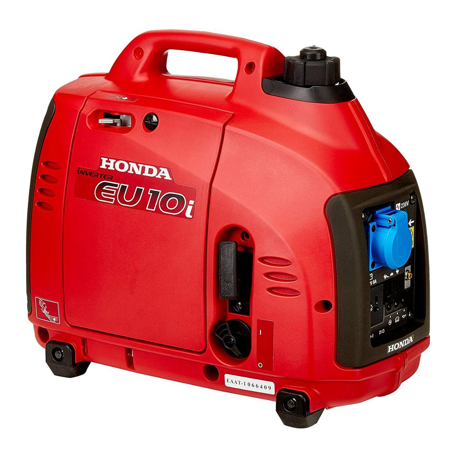
- EU10i
- Owner’s manual
-
Contents
-
Table of Contents
-
Troubleshooting
-
Bookmarks
Quick Links
Related Manuals for Honda EU10i
Summary of Contents for Honda EU10i
-
Page 2
Honda EU10i OWNER’S MANUAL MANUEL DE L’UTILISATEUR BEDIENUNGSANLEITUNG MANUAL DE EXPLICACIONES The‘‘e-SPEC’’mark symbolizes environmentally responsible technologies applied to Honda power equipment, which contains our wish to ‘‘preserve nature for generations to come.’’… -
Page 3
All information in this publication is based on the latest product information available at the time of approval for printing. Honda Motor Co., Ltd. reserves the right to make changes at any time without notice and without incurring any obligation. -
Page 4: Table Of Contents
Carburetor Modification for High Altitude Operation GENERATOR USE …………….25 STOPPING THE ENGINE …………..37 MAINTENANCE …………….39 TRANSPORTING/STORAGE …………46 TROUBLESHOOTING …………… 48 SPECIFICATIONS …………….50 WIRING DIAGRAM …………….52 MAJOR Honda DISTRIBUTOR ADDRESSES …….. . 56…
-
Page 5: Safety Instructions
SAFETY INSTRUCTIONS IMPORTANT SAFETY INFORMATION Honda generators are designed for use with electrical equipment that has suitable power requirements. Other uses can result in injury to the operator or damage to the generator and other property. Most injuries or property damage can be prevented if you follow all instructions in this manual and on the generator.
-
Page 6
Carbon Monoxide Hazards Exhaust contains poisonous carbon monoxide, a colorless, odorless gas. Breathing exhaust can cause loss of consciousness and may lead to death. If you run the generator in an area that is confined, or even partially enclosed area, the air you breathe could contain dangerous amount of exhaust gas. -
Page 7
Fire and Burn Hazards Do not use the generator in areas with a high risk of fire. When installed in ventilated rooms, additional requirements for fire and explosion protection shall be observed. The exhaust system gets hot enough to ignite some materials. Keep the generator at least 1 meter (3 feet) away from buildings and other equipment during operation. -
Page 8
Do not throw it in the trash or pour it on the ground. An improperly disposed battery can hurt the environment. Always confirm local regulations for battery disposal. Contact your Honda servicing dealer for a replacement. -
Page 9: Safety Label Locations
Read the labels and safety notes and precautions described in this manual carefully. If a label comes off or becomes hard to read, contact your Honda dealer for a replacement. For European model: G, GW, B, F, W types…
-
Page 10
Honda generator is designed to give safe and dependable service if operated according to instructions. Read and understand the Owner’s Manual before operating the generator. Failure to do so could result in personal injury or equipment damage. Exhaust contains poisonous carbon monoxide, a colorless, odorless gas. -
Page 11
Stop the engine before refueling. Gasoline is extremely flammable and explosive under certain conditions. Refuel in a well ventilated area with the engine stopped. Keep away from cigarette, smoke and sparks when refueling the generator. Always refuel in a well ventilated location. Wipe up spilled gasoline at once. -
Page 12
U type… -
Page 13: Ce Mark And Noise Label Locations
CE mark and noise label locations G, GW, B, F, W types NOISE LABEL CE MARK Manufacturer and address Performance class IP code Dry mass (weight)
-
Page 14: Component Identification
COMPONENT IDENTIFICATION FUEL CAP VENT LEVER CHOKE LEVER FUEL FILLER CAP CONTROL PANEL LEFT SIDE MAINTENANCE COVER STARTER GRIP ENGINE SWITCH FRAME SERIAL NUMBER SPARK PLUG MAINTENANCE COVER MUFFLER Record the frame serial number in the space below. You will need this serial number when ordering parts.
-
Page 15: Control Panel
CONTROL PANEL G, GW, B, F, W types AC RECEPTACLE PARALLEL OPERATION SOCKETS ECO THROTTLE SWITCH GROUND TERMINAL OIL ALERT INDICATOR LIGHT OVERLOAD INDICATOR LIGHT OUTPUT INDICATOR LIGHT DC RECEPTACLE DC CIRCUIT PROTECTOR…
-
Page 16
U type AC RECEPTACLE… -
Page 17
Eco Throttle ECO: Engine speed is kept at idle automatically when the electrical appliance is disconnected and it returns to the proper speed by the electrical load when electrical appliance is connected. This position is recommended to minimize the fuel consumption while in operation. Eco Throttle system does not operate sufficiently if the electrical appliance requires the momentary electric power. -
Page 18: Pre-Operation Check
PRE-OPERATION CHECK Be sure to check the generator on a level surface with the engine stopped. Check the engine oil level. Using non detergent oil or 2-stroke engine oil could shorten the engine’s service life. Recommended oil Use 4-stroke motor oil that meets or exceeds the requirements for API service category SE or later (or equivalent).
-
Page 19
Loosen the cover screw and remove the left side maintenance cover. (see page Remove the oil filler cap, and wipe the dipstick with a clean rag. Check the oil level by inserting the dipstick in the filler hole without screwing it in. -
Page 20
Check the fuel level. Check the fuel level. Refill the fuel tank if the fuel level is low. After refueling, tighten the fuel filler cap securely. Use automotive unleaded gasoline with a Research Octane Number of 91 or higher (a Pump Octane Number of 86 or higher). Never use stale or contaminated gasoline or an oil/gasoline mixture. -
Page 21
Gasolines Containing Alcohol If you decide to use a gasoline containing alcohol (gasohol), be sure its octane rating is at least as high as that recommended by Honda. There are two types of ‘‘gasohol’’: one containing ethanol, and the other containing methanol. -
Page 22
Check the air cleaner. Check the air cleaner element to be sure it is clean and in good condition. Loosen the cover screw and remove the left side maintenance cover. Press the latch tab on the top of the air cleaner body, remove the air cleaner cover, check the element. -
Page 23: Starting The Engine
STARTING THE ENGINE Before starting the engine disconnect any load from the AC receptacle. Turn the fuel cap lever fully clockwise to the ON position. Turn the fuel cap vent lever to the OFF position when transporting the generator. FUEL CAP VENT LEVER Turn the engine switch to the ON position.
-
Page 24
Move the choke lever to the CLOSED position. Do not use the choke when the engine is warm or the air temperature is high. CHOKE LEVER CLOSED CLOSED Pull the starter grip lightly until you feel resistance, then pull the starter grip briskly toward in the direction of the arrow as shown below. -
Page 25
Move the choke lever to the OPEN position as the engine warms up. CHOKE LEVER OPEN If the engine stops and will not restart, check the engine oil level (see pages ) before troubleshooting in other areas. -
Page 26
High altitude performance can be improved by specific modifications to the carburetor. If you always operate your generator at altitudes above 1,500 meters (5,000 feet), have your authorized Honda servicing dealer perform this carburetor modification. This engine, when operated at high altitude with the carburetor modifications for high altitude use, will meet each emission standard throughout its useful life. -
Page 27: Generator Use
GENERATOR USE Be sure to ground the generator when the connected equipment is grounded. Do not connect to a building’s electrical system unless an isolation switch has been installed by a qualified electrician. Connections for standby power to a building’s electrical system must be made by a qualified electrician and must comply with all applicable laws and electrical codes.
-
Page 28
Do not exceed the current limit specified for any one receptacle. Do not connect the generator to a household circuit. This could cause the damage to the generator or to electrical appliances in the house. Do not modify or use the generator for other purposes than it is intended for. -
Page 29
AC applications Start the engine and make sure the green output indicator comes on. Confirm that the appliance to be used is switched off, and plug in the appliance. PLUG OUTPUT INDICATOR OVERLOAD INDICATOR LIGHT (GREEN) LIGHT (RED) Substantial overloading that continuously lights the overload indicator light (red) may damage the generator. -
Page 30
When an electric motor is started, both the Overload indicator (red) and the Output indicator (green) may go on simultaneously. This is normal if the Overload indicator (red) goes off after about five (5) seconds. If the Overload indicator (red) stays on, consult your Honda generator dealer. -
Page 31
Parallel operation Please read the item ‘‘GENERATOR USE’’ before connecting any equipment to be used. Use only a special cable for parallel operation (sold separately). PARALLEL OPERATION SOCKETS SPECIAL CABLE FOR PARALLEL OPERATION (SOLD SEPARATELY) Make sure that the electrical rating of the tool or appliance does not exceed that of the generator. -
Page 32
Never connect the different generator models and types. Never connect a cable other than the special cable for parallel operation. Connect and remove the special cable for parallel operation with the engine stopped. For single operation, the special cable for parallel operation must be removed. -
Page 33
Be sure to ground the generator when the connected equipment is grounded. GROUND TERMINAL GROUND TERMINAL Start each engine according to ‘‘STARTING THE ENGINE’’. When the output indicator light (green) does not light and the overload indicator light (red) lights instead, set the engine switch to STOP, stop the engine once, and then start the engine again. -
Page 34
Switch on the equipment to be used. The output indicator light (green) will light. In case of normal operation In case of overload operation or short-circuit OVERLOAD INDICATOR LIGHT OUTPUT INDICATOR LIGHT (RED) (GREEN) In case of overload operation (refer to page ) or when trouble occurs for the equipment being used, the output indicator light (green) will go out, the overload indicator light (red) will light… -
Page 35
When equipment requiring a large starting power, like a motor etc., is used, the overload indicator light (red) and the output indicator light (green) may light together for a short time (about 4 sec), but this is no abnormality. After start of the equipment, the overload indicator light (red) will go out and the output indicator light (green) will stay lit. -
Page 36
DC Application The DC receptacle may be used for charging 12 volt automotive-type batteries only. In DC operation, turn the eco throttle switch to the OFF position. Connect the charging cable to the DC receptacle of the generator and then to the battery terminals. CHARGING CABLE (SOLD SEPARATELY: G, B, F, W types) To prevent the possibility of creating a spark near the battery,… -
Page 37
Batteries produce explosive gases: If ignited, and explosion can cause serious injury or blindness. Provide adequate ventilation when charging. CHEMICAL HAZARD: Battery electrolyte contains sulfuric acid. Contact with eyes or skin, even through clothing, may cause severe burns. Wear a faceshield and protective clothing. Keep flames and sparks away, and do not smoke in the area. -
Page 38
Oil Alert system The Oil Alert system is designed to prevent engine damage caused by an insufficient amount of oil in the crankcase. Before the oil level in the crankcase falls below a safe limit, the Oil Alert system will automatically shut down the engine (the engine switch will remain in the ON position). -
Page 39: Stopping The Engine
STOPPING THE ENGINE To stop the engine in an emergency, turn the engine switch to the OFF position. IN NORMAL USE: Switch off the connected equipment and pull the inserted plug. PLUG Turn the engine switch to the OFF position. ENGINE SWITCH…
-
Page 40
Turn the fuel cap vent lever fully counterclockwise to the OFF position. FUEL CAP VENT LEVER Be sure the fuel cap vent lever and the engine switch are OFF when stopping, transporting and/or storing the generator. When parallel operation has been executed, pull the special cable for parallel operation. -
Page 41: Maintenance
Every 2 years (Replace if necessary) (2) Service more frequently when used in dusty areas. These items should be serviced by your Honda servicing dealer, unless you have the proper tools and are mechanically proficient. Refer to the Honda shop manual for service procedures.
-
Page 42
CHANGING OIL Drain the oil while the engine is still warm to assure rapid and complete draining. Make sure to turn the engine switch and the fuel cap vent lever OFF before draining. Loosen the cover screw and remove the left side maintenance cover. Remove the oil filler cap. -
Page 43
AIR CLEANER SERVICE A dirty air cleaner will restrict air flow to the carburetor. To prevent carburetor malfunction, service the air cleaner regularly. Service more frequently when operating the generator in extremely dusty areas. Do not use gasoline or low flash point solvents for cleaning. They are flammable and explosive under certain conditions. -
Page 44
SPARK PLUG SERVICE RECOMMENDED SPARK PLUG: CR4HSB (NGK) U14FSR-UB (DENSO) To ensure proper engine operation, the spark plug must be properly gapped and free of deposits. Remove the spark plug maintenance cover. SPARK PLUG MAINTENANCE COVER Remove the spark plug cap. Clean any dirt from around the spark plug base. -
Page 45
Visually inspect the spark plug. Discard it if the insulator is cracked, chipped, or fouled. Clean the spark plug with a wire brush if it is to be reused. Measure the plug gap with a feeler gauge. Correct as necessary by carefully bending the side electrode. The gap should be: 0.6 0.7 mm (0.024 0.028 in) 0.6 0.7 mm… -
Page 46
SPARK ARRESTER MAINTENANCE (Equipped type) If the generator has been running, the muffler will be very hot. Allow it to cool before proceeding. The spark arrester must be serviced every 100 hours to maintain its efficiency. Remove the four 5 mm screws, and remove the muffler protector. MUFFLER PROTECTOR 5 mm SCREW Remove the three 6 mm bolts, and remove the muffler, the spark… -
Page 47
Use a brush to remove carbon deposits from the spark arrester screen. Inspect the spark arrester screen for holes or tears. Replace if necessary. Check the muffler gasket; replace if damaged. Reinstall the muffler gasket, the spark arrester, the muffler and the muffler protector in the reverse order of removal. -
Page 48: Transporting/Storage
TRANSPORTING/STORAGE To prevent fuel spillage when transporting or during temporary storage, the generator should be secured upright in its normal operating position, with the engine switch OFF. The fuel cap vent lever is turned fully counterclockwise to the OFF position. When transporting the generator: Do not overfill the tank (there should be no fuel in the filler neck).
-
Page 49
Turn the engine switch to the ON position, and loosen the carburetor drain screw and drain the gasoline from the carburetor into a suitable container. With the drain screw loosened remove the spark plug cap, and pull the starter grip 3 to 4 times to drain the gasoline from the fuel pump. -
Page 50: Troubleshooting
(see pages Is the spark plug Clean, readjust in good gap and dry the condition? spark plug. Replace it if necessary (see pages If the engine still does not start, take the generator to an authorized Honda dealer.
-
Page 51
Appliance does not operate: Is the output indicator ON? Take the Is the Overload generator to an indicator ON? authorized Honda dealer. Check the Take the electrical NO DEFECTS generator to an appliance or authorized equipment for Honda dealer. any defects. -
Page 52: Specifications
SPECIFICATIONS Dimensions and Weight Model EU10i Description code EZGA Length 451 mm (17.8 in) Width 242 mm (9.5 in) Height 379 mm (14.9 in) Dry weight 13 kg (29 lbs) Engine Model GXH50 Engine type 4-stroke, overhead valve, single cylinder Displacement 49.4 cm (3.01 cu-in)
-
Page 53
Noise EU10i Model G, GW, B, F, W Type 72 dB Sound pressure level (Lp ) According to 98/37/EC Microphone point CONTROL PANEL Center 1.60 m 1.0 m 87 dB Guaranteed sound power level (L Tested by 2000/14/EC ‘‘the figures quoted are emission levels and are not necessarily safe working levels. -
Page 54: Wiring Diagram
WIRING DIAGRAM AC Noise Filter AC, NF BLACK ACOR AC Output Receptacle YELLOW Capacitor BLUE Composite Socket GREEN Control Panel Block DC, D DC Diode WHITE DC, NF DC Noise Filter BROWN DCOR DC Output Receptacle LIGHT GREEN DC, W DC Winding GRAY EcoSw…
-
Page 55
G, GW, B, F, W type… -
Page 56
U type… -
Page 57
RECEPTACLE Type Shape G, GW… -
Page 58: Major Honda Distributor Addresses
MAJOR Honda DISTRIBUTOR ADDRESSES For further information, please contact Honda Customer Information Centre at the following address or telephone number: AUSTRIA CYPRUS FRANCE Honda Motor Europe (North) Alexander Dimitriou & Sons Ltd. HONDA RELATIONS CLIENTS Hondastraße 1 162, Yiannos Kranidiotis Avenue…
-
Page 59
381 11 3820 301 info hondapower.pl http://www.hondasrbija.co.yu LITHUANIA PORTUGAL SLOVAKIA REPUBLIC JP Motor Ltd Honda Portugal, S.A. Honda Slovakia, spol. s r.o. Kubiliaus str. 6 Abrunheira Prievozská 6 — 821 09 Bratislava 08234 Vilnius 2714-506 Sintra Slovak Republic Tel. : 370 5 276 5259 Tel. -
Page 60
SPAIN & TURKEY AUSTRALIA Las Palmas province Anadolu Motor Uretim Ve Honda Australia Motorcycle (Canary Islands) Pazarlama AS (ANPA) and Power Equipment Pty. Ltd Greens Power Products, S.L. Esentepe mah. Anadolu 1954-1956 Hume Highway Avda. Ramon Ciurans, 2 Cad. No: 5…

- Manuals
- Brands
- Honda Manuals
- Portable Generator
- EU10i
- Owner’s manual
-
Contents
-
Table of Contents
-
Troubleshooting
-
Bookmarks
Quick Links
Related Manuals for Honda EU10i
Summary of Contents for Honda EU10i
-
Page 2
Honda EU10i OWNER’S MANUAL MANUEL DE L’UTILISATEUR BEDIENUNGSANLEITUNG MANUAL DE EXPLICACIONES The‘‘e-SPEC’’mark symbolizes environmentally responsible technologies applied to Honda power equipment, which contains our wish to ‘‘preserve nature for generations to come.’’… -
Page 4
All information in this publication is based on the latest product information available at the time of approval for printing. Honda Motor Co., Ltd. reserves the right to make changes at any time without notice and without incurring any obligation. -
Page 5: Table Of Contents
Carburetor Modification for High Altitude Operation GENERATOR USE …………….25 STOPPING THE ENGINE …………..37 MAINTENANCE …………….39 TRANSPORTING/STORAGE …………46 TROUBLESHOOTING …………… 48 SPECIFICATIONS …………….50 WIRING DIAGRAM …………….52 MAJOR Honda DISTRIBUTOR ADDRESSES …….. . 56…
-
Page 6: Safety Instructions
SAFETY INSTRUCTIONS IMPORTANT SAFETY INFORMATION Honda generators are designed for use with electrical equipment that has suitable power requirements. Other uses can result in injury to the operator or damage to the generator and other property. Most mishaps can be prevented if you follow all instructions in this manual and on the generator.
-
Page 7
Carbon Monoxide Hazards Exhaust contains poisonous carbon monoxide, a colorless, odorless gas. Breathing exhaust can cause loss of consciousness and may lead to death. If you run the generator in an area that is confined, or even partially enclosed area, the air you breathe could contain dangerous amount of exhaust gas. -
Page 8
Fire and Burn Hazards Do not use the generator in areas with a high risk of fire. When installed in ventilated rooms, additional requirements for fire and explosion protection shall be observed. The exhaust system gets hot enough to ignite some materials. −… -
Page 9
Do not throw it in the trash or pour it on the ground. An improperly disposed battery can hurt the environment. Always confirm local regulations for battery disposal. Contact your Honda servicing dealer for a replacement. -
Page 10: Safety Label Locations
Read the labels and safety notes and precautions described in this manual carefully. If a label comes off or becomes hard to read, contact your Honda dealer for a replacement. For European model: G, GW, B, F, W types…
-
Page 11
Honda generator is designed to give safe and dependable service if operated according to instructions. Read and understand the Owner’s Manual before operating the generator. Failure to do so could result in personal injury or equipment damage. Exhaust contains poisonous carbon monoxide, a colorless, odorless gas. -
Page 12
Stop the engine before refueling. Gasoline is extremely flammable and explosive under certain conditions. Refuel in a well ventilated area with the engine stopped. Keep away from cigarette, smoke and sparks when refueling the generator. Always refuel in a well-ventilated location. Wipe up spilled gasoline at once. -
Page 13
U type… -
Page 14: Ce Mark And Noise Label Locations
CE mark and noise label locations G, GW, B, F, W types NOISE LABEL CE MARK Manufacturer and address Maximum ambient temperature Performance class IP code Maximum altitude Dry weight…
-
Page 15: Component Identification
COMPONENT IDENTIFICATION FUEL CAP VENT LEVER CHOKE LEVER FUEL FILLER CAP CONTROL PANEL LEFT SIDE MAINTENANCE COVER STARTER GRIP ENGINE SWITCH FRAME SERIAL NUMBER SPARK PLUG MAINTENANCE COVER MUFFLER Record the frame serial number in the space below. You will need this serial number when ordering parts.
-
Page 16: Control Panel
CONTROL PANEL G, GW, F, W types AC RECEPTACLE PARALLEL OPERATION SOCKETS ECO THROTTLE SWITCH GROUND TERMINAL OIL ALERT INDICATOR LIGHT OVERLOAD INDICATOR LIGHT OUTPUT INDICATOR LIGHT DC RECEPTACLE DC CIRCUIT PROTECTOR…
-
Page 17
B type AC RECEPTACLE U type AC RECEPTACLE… -
Page 18
Eco Throttle ECO: Engine speed is kept at idle automatically when the electrical appliance is disconnected and it returns to the proper speed by the electrical load when electrical appliance is connected. This position is recommended to minimize the fuel consumption while in operation. Eco Throttle system does not operate sufficiently if the electrical appliance requires the momentary electric power. -
Page 19: Pre-Operation Check
PRE-OPERATION CHECK Be sure to check the generator on a level surface with the engine stopped. Check the engine oil level. Using non detergent oil or 2-stroke engine oil could shorten the engine’s service life. Recommended oil Use 4-stroke motor oil that meets or exceeds the requirements for API service category SE or later (or equivalent).
-
Page 20
Loosen the cover screw and remove the left side maintenance cover. (see page Remove the oil filler cap, and wipe the dipstick with a clean rag. Check the oil level by inserting the dipstick in the filler hole without screwing it in. -
Page 21: Starting The Engine
Check the fuel level. Check the fuel level. Refill the fuel tank if the fuel level is low. After refueling, tighten the fuel filler cap securely. Use automotive unleaded gasoline with a Research Octane Number of 91 or higher (a Pump Octane Number of 86 or higher). Never use stale or contaminated gasoline or an oil/gasoline mixture.
-
Page 22
Gasolines Containing Alcohol If you decide to use a gasoline containing alcohol (gasohol), be sure it’s octane rating is at least as high as that recommended by Honda. There are two types of ‘‘gasohol’’: one containing ethanol, and the other containing methanol. -
Page 23
Check the air cleaner. Check the air cleaner element to be sure it is clean and in good condition. Loosen the cover screw and remove the left side maintenance cover. Press the latch tab on the top of the air cleaner body, remove the air cleaner cover, check the element. -
Page 24
STARTING THE ENGINE Before starting the engine disconnect any load from the AC receptacle. Turn the fuel cap lever fully clockwise to the ON position. Turn the fuel cap vent lever to the OFF position when transporting the generator. FUEL CAP VENT LEVER Turn the engine switch to the ON position. -
Page 25
Move the choke lever to the CLOSED position. Do not use the choke when the engine is warm or the air temperature is high. CHOKE LEVER CLOSED CLOSED Pull the starter grip lightly until you feel resistance, then pull the starter grip briskly toward in the direction of the arrow as shown below. -
Page 26
Move the choke lever to the OPEN position as the engine warms up. CHOKE LEVER OPEN If the engine stops and will not restart, check the engine oil level (see pages ) before troubleshooting in other areas. -
Page 27: Carburetor Modification For High Altitude Operation
High altitude performance can be improved by specific modifications to the carburetor. If you always operate your generator at altitudes above 1,500 meters (5,000 feet), have your authorized Honda servicing dealer perform this carburetor modification. This engine, when operated at high altitude with the carburetor modifications for high altitude use, will meet each emission standard throughout its useful life.
-
Page 28: Generator Use
GENERATOR USE Be sure to ground the generator when the connected equipment is grounded. Do not connect to a building’s electrical system unless an isolation switch has been installed by a qualified electrician. Connections for standby power to a building’s electrical system must be made by a qualified electrician and must comply with all applicable laws and electrical codes.
-
Page 29
Do not exceed the current limit specified for any one receptacle. Do not connect the generator to a household circuit. This could cause the damage to the generator or to electrical appliances in the house. Do not modify or use the generator for other purposes than it is intended for. -
Page 30
AC applications Start the engine and make sure the green output indicator comes on. Confirm that the appliance to be used is switched off, and plug in the appliance. PLUG OUTPUT INDICATOR OVERLOAD INDICATOR LIGHT (GREEN) LIGHT (RED) Substantial overloading that continuously lights the overload indicator light (red) may damage the generator. -
Page 31
When an electric motor is started, both the Overload indicator (red) and the Output indicator (green) may go on simultaneously. This is normal if the Overload indicator (red) goes off after about five (5) seconds. If the Overload indicator (red) stays on, consult your Honda generator dealer. -
Page 32
Parallel operation Please read the item ‘‘GENERATOR USE’’ before connecting any equipment to be used. Use only a special cable for parallel operation (sold separately). PARALLEL OPERATION SOCKETS SPECIAL CABLE FOR PARALLEL OPERATION (SOLD SEPARATELY) Make sure that the electrical rating of the tool or appliance does not exceed that of the generator. -
Page 33
Never connect the different generator models and types. Never connect a cable other than the special cable for parallel operation. Connect and remove the special cable for parallel operation with the engine stopped. For single operation, the special cable for parallel operation must be removed. -
Page 34
Be sure to ground the generator when the connected equipment is grounded. GROUND TERMINAL GROUND TERMINAL Start each engine according to ‘‘STARTING THE ENGINE’’. When the output indicator light (green) does not light and the overload indicator light (red) lights instead, set the engine switch to STOP, stop the engine once, and then start the engine again. -
Page 35
Switch on the equipment to be used. The output indicator light (green) will light. In case of normal operation In case of overload operation or short-circuit OVERLOAD INDICATOR LIGHT OUTPUT INDICATOR LIGHT (RED) (GREEN) In case of overload operation (refer to page ) or when trouble occurs for the equipment being used, the output indicator light (green) will go out, the overload indicator light (red) will light… -
Page 36
When equipment requiring a large starting power, like a motor etc., is used, the overload indicator light (red) and the output indicator light (green) may light together for a short time (about 4 sec), but this is no abnormality. After start of the equipment, the overload indicator light (red) will go out and the output indicator light (green) will stay lit. -
Page 37
DC Application The DC receptacle may be used for charging 12 volt automotive-type batteries only. In DC operation, turn the eco throttle switch to the OFF position. Connect the charging cable to the DC receptacle of the generator and then to the battery terminals. CHARGING CABLE (SOLD SEPARATELY: G, B, F, W types) To prevent the possibility of creating a spark near the battery,… -
Page 38
Batteries produce explosive gases: If ignited, and explosion can cause serious injury or blindness. Provide adequate ventilation when charging. CHEMICAL HAZARD: Battery electrolyte contains sulfuric acid. Contact with eyes or skin, even through clothing, may cause severe burns. Wear a faceshield and protective clothing. Keep flames and sparks away, and do not smoke in the area. -
Page 39
Oil Alert system The Oil Alert system is designed to prevent engine damage caused by an insufficient amount of oil in the crankcase. Before the oil level in the crankcase falls below a safe limit, the Oil Alert system will automatically shut down the engine (the engine switch will remain in the ON position). -
Page 40: Stopping The Engine
STOPPING THE ENGINE To stop the engine in an emergency, turn the engine switch to the OFF position. IN NORMAL USE: Switch off the connected equipment and pull the inserted plug. PLUG Turn the engine switch to the OFF position. ENGINE SWITCH…
-
Page 41
Turn the fuel cap vent lever fully counterclockwise to the OFF position. FUEL CAP VENT LEVER Be sure the fuel cap vent lever and the engine switch are OFF when stopping, transporting and/or storing the generator. When parallel operation has been executed, pull the special cable for parallel operation. -
Page 42: Maintenance
Fuel line Check Service more frequently when used in dusty areas. These items should be serviced by your Honda servicing dealer, unless you have the proper tools and are mechanically proficient. Refer to the Honda shop manual for service procedures.
-
Page 43
CHANGING OIL Drain the oil while the engine is still warm to assure rapid and complete draining. Make sure to turn the engine switch and the fuel cap vent lever OFF before draining. Loosen the cover screw and remove the left side maintenance cover. Remove the oil filler cap. -
Page 44
AIR CLEANER SERVICE A dirty air cleaner will restrict air flow to the carburetor. To prevent carburetor malfunction, service the air cleaner regularly. Service more frequently when operating the generator in extremely dusty areas. Do not use gasoline or low flash point solvents for cleaning. They are flammable and explosive under certain conditions. -
Page 45
SPARK PLUG SERVICE RECOMMENDED SPARK PLUG: CR4HSB (NGK) U14FSR-UB (DENSO) To ensure proper engine operation, the spark plug must be properly gapped and free of deposits. Remove the spark plug maintenance cover. SPARK PLUG MAINTENANCE COVER Remove the spark plug cap. Clean any dirt from around the spark plug base. -
Page 46
Visually inspect the spark plug. Discard it if the insulator is cracked or chipped. Clean the spark plug with a wire brush if it is to be reused. Measure the plug gap with a feeler gauge. Correct as necessary by carefully bending the side electrode. The gap should be: 0.6 0.7 mm (0.024 0.028 in) −… -
Page 47
SPARK ARRESTER MAINTENANCE (Equipped type) If the generator has been running, the muffler will be very hot. Allow it to cool before proceeding. The spark arrester must be serviced every 100 hours to maintain its efficiency. Remove the four 5 mm screws, and remove the muffler protector. MUFFLER PROTECTOR 5 mm SCREW Remove the three 6 mm bolts, and remove the muffler, the spark… -
Page 48
Use a brush to remove carbon deposits from the spark arrester screen. Inspect the spark arrester screen for holes or tears. Replace if necessary. Check the muffler gasket; replace if damaged. Reinstall the muffler gasket, the spark arrester, the muffler and the muffler protector in the reverse order of removal. -
Page 49: Transporting/Storage
TRANSPORTING/STORAGE To prevent fuel spillage when transporting or during temporary storage, the generator should be secured upright in its normal operating position, with the engine switch OFF. The fuel cap vent lever is turned fully counterclockwise to the OFF position. When transporting the generator: Do not overfill the tank (there should be no fuel in the filler neck).
-
Page 50
Turn the engine switch ON, and loosen the carburetor drain screw and drain the gasoline from the carburetor into a suitable container. With the drain screw loosened remove the spark plug cap, and pull the starter grip 3 to 4 times to drain the gasoline from the fuel pump. -
Page 51: Troubleshooting
(see pages Is the spark plug Clean, readjust in good gap and dry the condition? spark plug. Replace it if necessary (see pages If the engine still does not start, take the generator to an authorized Honda dealer.
-
Page 52
Appliance does not operate: Is the Output indicator ON? Take the Is the Overload generator to an indicator ON? authorized Honda dealer. Check the Take the electrical NO DEFECTS generator to an appliance or authorized equipment for Honda dealer. any defects. -
Page 53: Specifications
SPECIFICATIONS Dimensions and Weight Model EU10i Description code EZGA Length 451 mm (17.8 in) Width 242 mm (9.5 in) Height 379 mm (14.9 in) Dry weight 13 kg (29 lbs) Engine Model GXH50 Engine type 4-stroke, overhead valve, single cylinder Displacement 49.4 cm (3.01 cu-in)
-
Page 54
Noise EU10i Model G, GW, B, F, W Type 72 dB Sound pressure level (Lp ) According to 98/37/EC Microphone point CONTROL PANEL Center 1.60 m 1.0 m 87 dB Guaranteed sound power level (L Tested by 2000/14/EC ‘‘the figures quoted are emission levels and are not necessarily safe working levels. -
Page 55: Wiring Diagram
WIRING DIAGRAM AC, NF AC Noise Filter BLACK ACOR AC Output Receptacle YELLOW Capacitor BLUE Composite Socket GREEN Control Panel Block DC, D DC Diode WHITE DC, NF DC Noise Filter BROWN DCOR DC Output Receptacle LIGHT GREEN DC, W DC Winding GRAY EcoSw…
-
Page 56
G, GW, B, F, W type… -
Page 57
U type… -
Page 58
RECEPTACLE Shape Type G, GW… -
Page 59: Major Honda Distributor Addresses
MAJOR Honda DISTRIBUTOR ADDRESSES For further information, please contact Honda Customer Information Centre at the following address or telephone number: AUSTRIA CROATIA FINLAND Honda Motor Europe (North) Hongoldonia d.o.o. OY Brandt AB. Hondastraße 1 Jelkovecka Cesta 5 Tuupakantie 7B 2351 Wiener Neudorf 10360 Sesvete −…
-
Page 60
@ LITHUANIA PORTUGAL SLOVAKIA REPUBLIC JP Motor Ltd Honda Portugal, S.A. Kubiliaus str. 6 Abrunheira Honda Slovakia, spol. s r.o. 08234 Vilnius 2714-506 Sintra Prievozská 6 — 821 09 Tel. : + 370 5 276 5259 Tel. : + 351 21 915 53 33… -
Page 61
SLOVENIA UKRAINE AS Domzale Moto Center D.O. Honda Ukraine LLC 101 Volodymyrska Str. — Build. 2 Blatnica 3A Kiev 01033 1236 Trzin Tel. : + 380 44 390 1414 Tel. : + 386 1 562 22 42 Fax : +… -
Page 62
Le label ‘‘e-SPEC’’ a été créé à l’origine pour illustrer notre engagement à ‘‘préserver la nature pour les générations futures’’ et témoigner de nos efforts en ce sens. Il est maintenant devenu le symbole des technologies respectueuses de l’environnment appliquées aux moteurs, aux produits d’équipement et aux moteurs hors-bord Honda. -
Page 64
En cas de dérangement, ou pour toute question concernant ce groupe électrogène, veuillez vous adresser au revendeur local Honda. Ce groupe électrogène Honda a été conçu pour assurer un service sûr et fiable dans le conditions d’utilisation conformes aux instructions. Avant d’utiliser ce groupe, veuillez lire et assimiler le contenu de ce manuel. -
Page 65
. 25 ARRÊT DU MOTEUR ………………… 37 ENTRETIEN ……………………39 TRANSPORT/REMISAGE ……………….. . 46 DÉPISTAGE DES PANNES ………………. . 48 CARACTÉRISTIQUES ………………..50 SCHÉMA DE CABLAGE ………………..52 ADRESSES DES PRINCIPAUX CONCESSIONNAIRES Honda ……56… -
Page 66: Consignes De Securite
CONSIGNES DE SECURITE INFORMATIONS DE SECURITE IMPORTANTES Les groupes électrogènes Honda sont destinés à alimenter des équipements électriques dont la puissance requise est appropriée. D’autres usages pourraient occasionner des blessures à l’opérateur ou des dommages au groupe électrogène et à d’autres biens.
-
Page 67
Dangers du monoxyde de carbone Les gaz d’échappement contiennent du monoxyde de carbone, un gaz toxique incolore et inodore. Les gaz d’échappement peuvent provoquer des évanouissements et être mortels. Si l’on fait fonctionner le groupe électrogène dans un endroit fermé ou même partiellement clos, l’air respiré… -
Page 68
Risques d’incendie et de brûlures Ne pas utiliser le groupe électrogène dans des endroits présentant des risques importants d’incendie. En cas d’installation dans un local ventilé, les exigences additionnelles requises pour la protection contre l’incendie et les explosions seront observées. Le système d’échappement chauffe suffisamment pour enflammer certaines matières. -
Page 69
Pour protéger l’environnement, ne pas jeter le groupe électrogène, la batterie, l’huile moteur usée, etc. aux ordures ou dans un endroit impropre. Pour leur mise au rebut, observer la réglementation locale ou consulter son concessionnaire Honda agrée. Jeter l’huile moteur usée de manière compatible avec l’environnement. Nous vous suggérons de l’amener dans un bidon scellé… -
Page 70: Emplacement Des Autocollants De Securite
Si un autocollant se détache ou devient difficile à lire, s’adresser à un concessionnaire Honda pour le faire remplacer. Pour le modèle européen: types G, GW, B, F, W MISE EN GARDE POUR LES PRISES…
-
Page 71
Les groupes électrogènes Honda ont été conçus pour assurer un f onctionnement sûr et fiable lorsqu’ils sont utilisés conformément aux instructions données. Prière de lire très attentivement le manuel du propriétaire avant d’utiliser le groupe électrogène afin de ne pas risquer de se blesser ou d’endommager l’équipement. -
Page 72
Avant de faire le plein de carburant, arrêter le moteur. L’essence est très inflammable et explosive dans certaines conditions. Faire l’appoint dans une zone bien aérée avec le moteur arrêté. Tenir à distance de cigarettes, fumée et étincelles en faisant l’appoint du générateur. -
Page 73
U type… -
Page 74
Emplacement de la marque CE et de l’étiquette sur le bruit Types G, GW, B, F, W ETIQUETTE BRUIT MARQUE CE Nom et adresse du fabricant Température ambiante maximale Classe de performances Code IP Altitude maximale Poids à sec… -
Page 75: Indentification Des Pièces
IDENTIFICATION DES PIÈCES LEVIER DÉVENT DU BOUHON DE CARBURANT LEVIER DE STARTER BOUCHON DE REMPLISSAGE D’ESSENCE PANNEAU DE COMMANDE COUVERCLE DE MAINTENANCE GAUCHE POIGNEE DE DEMARREUR CONTACTEUR DU MOTEUR NUMERO DE SERIE DU CHASSIS COUVERCLE DEMAINTENANCE DE BOUGIE D’ALLUMAGE SILENCIEUX Inscrire le numéro de série du châssis dans l’espace ci-dessous.
-
Page 76: Panneau De Commande
PANNEAU DE COMMANDE Types G, GW, F, W PRISES D’OPERATION EN PARALLELE PRISE SECTEUR COMMUTATEUR DE PAPILLON ECO BORNE DE TERRE TEMOIN D’ALERTE D’HUILE TEMOIN DE SURCHARGE TEMOIN DE SORTIE PRISE CC PROTECTEUR DE CIRCUIT CC…
-
Page 77
Type B PRISE SECTEUR Type U PRISE SECTEUR… -
Page 78
Eco Throttle ECO: Le régime moteur est automatiquement laissé au ralenti lorsque l’appareil électrique est déconnecté, et il revient à la bonne vitesse avec la charge électrique lorsque l’appareil électrique est connecté. Cette position est recommandée pour réduire la consommation d’essence pendant l’opération. -
Page 79: Contrôles Avant L’utilisation
CONTRÔLES AVANT L’UTILISATION Contrôler le groupe électrogène sur un sol horizontal avec le moteur arrêté. Vérifier le niveau d’huile moteur. L’utilisation d’une huile moteur non détergente ou 2 temps peut raccourcir la durée de service de moteur. Huile recommandée Utiliser une huile moteur 4 temps répondant ou dépassant les prescriptions pour la catégorie de service API SE ou ultérieure (ou équivalente).
-
Page 80
Desserrer la vis de couvercle, et déposer le couvercle de maintenance gauche (voir page Déposer le bouchon de dispositif de remplissage d’huile, et essuyer la jauge de niveau avec un chiffon propre. Vérifier le niveau d’huile en insérant la jauge de niveau dans l’orifice de dispositif de remplissage sans la visser. -
Page 81
Vérifier le niveau d’huile. Vérifier le niveau de carburant. Si le niveau de carburant est bas, remplir le réservoir de carburant. Après avoir fait le plein, bien resserrer le bouchon du réservoir. Utiliser de l’essence automobile sans plomb ayant un indice d’octane recherche d’au moins 91 (ou un indice d’octane pompe d’au moins 86). -
Page 82
Honda n’est pas en mesure d’approuver l’utilisation de carburants contenant du méthanol car la preuve n’est pas encore pleinement faite qu’ils sont bien adaptés. Avant de se ravitailler dans une station-service que l’on connaît mal, essaver de savoir si l’essence contient de l’alcool, quel est le type d’alcool utilisé… -
Page 83
Vérifier le filtre à air. Vérifier l’élément de filtre à air pour s’assurer qu’il est propre et en bon état. Desserrer la vis de couvercle, et déposer le couvercle de maintenance gauche. Enfoncer la languette de verrouillage située sur le haut du corps de filtre à air, déposer le couvercle de filtre à… -
Page 84: Mise En Marche Du Moteur
MISE EN MARCHE DU MOTEUR Avant de mettre en marche le moteur, déconnecter toute charge de la prise secteur. Tourner le levier de bouchon d’essence à fond dans le sens des aiguilles d’une montre vers la position ‘‘ON’’ (ouvert). Tourner le levier d’évent du bouchon de carburant à la position de fermeture (OFF) en transportant le générateur.
-
Page 85
Déplacer le levier de starter vers la position ‘‘CLOSED’’ (fermé). Ne pas utiliser le starter lorsque le moteur est chaud ou la température de l’air élevée. LEVIER DE STARTER FERME FERME Tirer doucement la poignée de lancement jusqu’à ce que l’on ressente une résistance, puis la tirer d’un coup sec dans le sens de la flèche comme sur la figure ci-dessous. -
Page 86
Déplacer le levier de starter vers la position ‘‘OPEN’’ (ouvert) dès que le moteur chauffe. LEVIER DE STARTER OUVERT Si le moteur s’arrête et ne redémarre pas, vérifier le niveau d’huile du moteur (voir page ) avant de rechercher l’origine du problème dans d’autres parties. -
Page 87: Modification Du Carburateur Pour Une Utilisation À Haute Altitude
On peut améliorer les performances en haute altitude en effectuant certaines modifications sur le carburateur. Si l’on utilise toujours le groupe électrogène à des altitudes supérieures à 1.500 mètres, demander au concessionnaire Honda agréé d’effectuer ces modifications du carburateur. Lors d’une utilisation en haute altitude, le moteur satisfera aux normes antipollution pendant toute sa durée de service si les…
-
Page 88: Utilisation
UTILISATION Ne pas manquer de mettre le générateur à la terre quand l’équipement connecté est mis à la terre. Ne pas raccorder le groupe électrogène au réseau électrique d’un bâtiment si un interrupteur d’isolement n’a pas été installé par un électricien qualifié. Le raccordement à…
-
Page 89
Ne pas dépasser la limite d’intensité spécifiée pour chaque prise. Ne pas raccorder le groupe électrogène au secteur. Ceci pourrait endommager le groupe ou les appareils électriques de la maison. Ne pas modifier le groupe électrogène et ne pas l’utiliser dans un autre but que celui prévu. -
Page 90
Applications CA Mettre le moteur en marche et s’assurer que le témoin de sortie vert s’allume. Confirmer que l’appareil à utiliser est hors tension, et brancher l’appareil. TEMOIN DE SORTIE FICHE TEMOIN DE SURCHARGE (VERT) (ROUGE) Une surcharge substantielle qui allume continuellement le témoin de surcharge (rouge) peut endommager le générateur. -
Page 91
Lorsqu’un moteur électrique démarre, il se peut que le témoin de surcharge (rouge) et le témoin de sortie (vert) s’allument tous deux simultanément. Ceci est normal si le témoin de surcharge (rouge) s’éteint après environ cinq (5) secondes. Si le témoin de surcharge (rouge) reste allumé, consulter le concessionnaire Honda de groupes électrogènes. -
Page 92
Opération parallèle Lire le point ‘‘UTILISATION DU GENERATEUR’’ avant de connecter tout équipement à utiliser. N’utiliser toujours qu’un câble spécial pour fonctionnement en parallèle (vendu séparément). PRISES DE FONCTIONNEMENT EN PARALLELE CABLE SPECIAL POUR OPERATION PARALLELE (VENDU SEPAREMENT) S’assurer que les caractéristiques électriques nominales de l’outil ou de l’appareil ne dépassent pas celles du groupe électrogène. -
Page 93
Ne jamais raccorder des modèles et types de groupes électrogènes différents. Ne jamais connecter un câble autre que le câble spécial pour opération parallèle. Connecter et déposer le câble spécial pour opération parallèle avec le moteur arrêté. Pour une opération unique, le câble spécial pour opération parallèle doit être déposé. -
Page 94
Ne pas manquer de mettre le générateur à la terre quand l’équipement connecté est mis à la terre. BORNE DE TERRE BORNE DE TERRE Démarrer chaque moteur en function de ‘‘MISE EN MARCHE DU MOTEUR’’. Lorsque le témoin de sortie (vert) ne s’allume pas et que le témoin de surcharge (rouge) s’allume à… -
Page 95
Mettre l’équipement à utiliser sous tension. Le témoin de sortie (vert) s’allume. En cas d’opération avec surcharge ou En cas d’opération normale de court-circuit TEMOIN DE SURCHARGE TEMOIN DE SORTIE (ROUGE) (VERT) En cas d’opération avec surcharge (se reporter à la page ) ou de panne pour l’équipement à… -
Page 96
Lorsqu’un équipement nécessitant une grande puissance de démarrage tel qu’un moteur, etc. est utilisé, les témoins de surcharge (rouge) et de sortie (vert) peuvent s’allumer ensemble pendant une courte durée (environ 4 sec.). mais ceci n’est pas anormal. Après le démarrage de l’équipement, le témoin de surcharge (rouge) s’éteint et le témoin de sortie (vert) reste allumé. -
Page 97
Applications CC La prise CC peut être utilisée pour la charge des seules batteries de type automobile 12 volts. En opération CC, tourner le commutateur de papillon ECO vers la position OFF. Connecter les câbles de charge à la prise CC du générateur, puis aux bornes de batterie. -
Page 98
Les batteries dégagent des gaz explosifs. S’ils s’enflamment, une explosion peut provoquer de graves brûlures de la peau ou des yeux. Assurer une aération adéquate pendant la charge. PRODUIT CHIMIQUE DANGEREUX: L’électrolyte de batterie contient de l’acide sulfurique. Un contact avec les yeux ou la peau, même à travers un vêtement, peut provoquer de graves brûlures. -
Page 99
Système Oil Alert Le système d’alerte d’huile est conçu pour empêcher des dommages au moteur causés par une quantité d’huile insuffisante dans le carter moteur. Avant que le niveau d’huile du carter moteur ne tombe en-deçà d’une limite sûre, le système d’alerte d’huile arrête automatiquement le moteur (le commutateur de moteur reste en position ‘‘ON’’… -
Page 100: Arrêt Du Moteur
ARRÊT DU MOTEUR Pour arrêter le moteur en cas d’urgence, tourner le commutateur de moteur vers la position ‘‘OFF’’ (arrêt). EN USAGE NORMAL: Mettre l’équipement connecté hors tension, et tirer la fiche insérée. FICHE Tourner le commutateur de moteur vers la position ‘‘OFF’’ (arrêt). FERME FERME CONTACTEUR D’ARRET MOTEUR…
-
Page 101
Tourner le levier d’évent du bouchon de carburant à fond dans le sens contraire des aiguilles d’une montre sur la position de fermeture (OFF). LEVIER D’EVENT DU BOUCHON DE CARBURANT ARRET ARRET Tourner sans faute le levier d’évent du bouchon de carburant et le commutateur de moteur sur la position de fermeture (OFF) pour l’arrêt, le transport et/ou l’entreposage du générateur. -
Page 102: Entretien
Entretenir plus fréquemment en cas d’utilisation dans des zones poussiéreuses. Confier l’entretien de ces points au concessionnaire Honda à moins que l’on ne dispose des outils appropriés et ne soit mécaniquement compétent. Pour les procédures d’entretien, voir le manuel d’atelier Honda.
-
Page 103
HUILE MOTEUR Vidanger l’huile alors que le moteur est encore chaud pour assurer une vidange rapide et complète. Tourner sans faute le commutateur de moteur et le levier d’évent du bouchon de carburant sur la position de fermeture (OFF) avant d’effectuer la vidange. Desserrer la vis de couvercle, et déposer le couvercle de maintenance gauche. -
Page 104
ENTRETIEN DU FILTRE À AIR Si le filtre à air est sale, le passage d’air vers le carburateur sera restreint. Pour prévenir toute avarie du carburateur, nettoyer le filtre à air régulièrement. Le nettoyer plus souvent, lorsque le groupe électrogène est utilisé dans un environnement poussièreux. Ne pas utiliser de l’essence, ou un solvant à… -
Page 105
ENTRETIEN DE LA BOUGIE D’ALLUMAGE BOUGIE D’ALLUMAGE RECOMMANDÉE: CR4HSB (NGK) U14FSR-UB (DENSO) Pour assurer un bon fonctionnement du moteur, l’écartement des électrodes de la bougie doit être correct et la bougie ne doit pas être encrassée. Déposer le couvercle de maintenance de bougie d’allumage. CAPUCHON DE BOUGIE D’ALLUMAGE Retirer le capuchon de bougie. -
Page 106
Procéder à un contrôle visuel de la bougie d’allumage. La jeter si son isolant est félé ou écaillé. Nettoyer la bougie avec une brosse métallique lorsqu’elle est réutilisable. Mesurer l’écartement des électrodes avec un calibre d’épaisseur. Le corriger si nécessaire enrecourbant avec soin l’électrode latérale. L’entrefer doit être égal à: 0,6 0,7 mm −… -
Page 107
ENTRETIEN DU PARE-ETINCELLES (Type équipé) Si le générateur a été utilisé, le silencieux est très chaud. Le laisser refroidir avant de procéder. Le pare-étincelles doit être entretenu toutes les 100 heures pour maintenir son efficacité. Déposer les quatre vis de 5 mm, et déposer le protecteur de silencieux. DISPOSITIF DE PROTECTION DU SILENCIEUX VIS DE 5 mm Déposer les trois boulons de 6 mm, et déposer le silencieux, le pare-étincelles et le… -
Page 108
Utilser une brosse pour éliminer les dépôts de calamine de la grille de pare-étincelles. Vérifier si la grille de pare-étincelles est trouée ou déchirée. Remplacer si nécessaire. Vérifier le joint de silencieux, remplacer s’il est endommagé. Reposer le joint de silencieux, le pare-étincelles, le silencieux et le protecteur de silencieux dans l’ordre inverse de la dépose. -
Page 109: Transport/Remisage
TRANSPORT/REMISAGE Pour éviter de répandre l’essence lors du transport ou pendant un remisage provisoir, le générateur doit être fixé verticalement dans sa position d’utilisation normale, avec le commutateur de moteur en position OFF (arrêt). Le levier d’évent du bouchon de carburant tourné à fond dans le sens contraire des aiguilles d’une montre sur la position de fermeture (OFF).
-
Page 110
Tourner le commutateur de moteur vers la position ‘‘ON’’ (marche), desserrer la vis de vidange de carburateur, et vidanger l’essence du carburateur dans un bidon approprié. La vis de vidange étant desserrée, déposer le capuchon de bougie d’allumage, et tirer la poignée de lanceur à 3 ou 4 reprises pour vidanger l’essence de la pompe à essence. -
Page 111: Dépistage Des Pannes
Est-ce que la bougie Nettoyer, régler le d’allumage est en jeu et sécher la bon état? bougie d’allumage. La remplacer si nécessaire (voir page Si le moteur ne démarre toujours pas, faire vérifier le groupe électrogène par un concessionaire Honda agréé.
-
Page 112
L’appareil ne fonctionne pas: Le témoin de sortie est-il allumé? Porter le groupe Le témoin de surcharge électrogène chez un est-il allumé? concessionaire Honda. Vérifier si l’appareil Porter le groupe ou l’équipement Pas de défaut électrogène chez un électrique n’est pas concessionaire défectueux. -
Page 113: Caractéristiques
CARACTÉRISTIQUES Dimension et poids Modèle EU10i Code descriptif EZGA Longueur 451 mm Largeur 242 mm Hauteur 379 mm Poids à sec 13 kg Moteur Modèle GXH50 Type de moteur 4 temps, soupape en tête, cylindre unique Cylindrée 49,4 cm Alésage Course ×…
-
Page 114
Bruit EU10i Modèle G, GW, B, F, W Type Niveau de pression sonore 72 dB (Lp ) Conformément à la directive 98/37/CE Point de microphone PANNEAU DE COMMANDE Centre 1,60 m 1,0 m 87 dB Niveau de puissance sonore garanti (L Testé… -
Page 115: Schéma De Cablage
SCHÉMA DE CABLAGE AC, NF Filter antiparasite CA NOIR ACOR Prise de sortie Ca JAUNE Condensateur BLEU Prise composite VERT Bloc de panneau de commande ROUGE DC, D Doide CC BALNC DC, NF Filtre antiparasite CC MARRON DCOR Prise de sortie CC VERT CLAIR DC, W Bobinage Cc…
-
Page 116
Type G, GW, B, F, W… -
Page 117
Type U… -
Page 118
PRICE Forme Type G, GW… -
Page 119: Adresses Des Principaux Concessionnaires Honda
ADRESSES DES PRINCIPAUX CONCESSIONNAIRES Honda Pour plus d’informations, s’adresser au Centre d’informations clients Honda à l’adresse ou numéro de téléphone suivants: AUSTRIA CROATIA FINLAND Honda Motor Europe (North) Hongoldonia d.o.o. OY Brandt AB. Hondastraße 1 Jelkovecka Cesta 5 Tuupakantie 7B…
-
Page 120
@ LITHUANIA PORTUGAL SLOVAKIA REPUBLIC JP Motor Ltd Honda Portugal, S.A. Kubiliaus str. 6 Abrunheira Honda Slovakia, spol. s r.o. 08234 Vilnius 2714-506 Sintra Prievozská 6 — 821 09 Tel. : + 370 5 276 5259 Tel. : + 351 21 915 53 33… -
Page 121
SLOVENIA UKRAINE AS Domzale Moto Center D.O. Honda Ukraine LLC 101 Volodymyrska Str. — Build. 2 Blatnica 3A Kiev 01033 1236 Trzin Tel. : + 380 44 390 1414 Tel. : + 386 1 562 22 42 Fax : +… -
Page 122
Honda EU10i BEDIENUNGSANLEITUNG ‘‘e-SPEC’’ wurde ursprünglich auf unseren Wunsch kreiert, die Natur auch für zukünftige Generationen zu erhalten. Nun symbolisiert dieses Logo umweltbewusste Technologien, die Honda bei ihren Motoren, elektrischen Einrichtungen, Außenmotoren usw. einsetzt. -
Page 124
Diese Anleitung erläutert den Betrieb und die Wartungsschritte für das Generatormodell EU10i. Das Handbuch enthält alle zur Zeit der Drucklegung erhältlichen neuesten Informationen. Honda Motor Co., Ltd. behält sich das Recht vor, jederzeit ohne Vorankündigung Änderungen vorzunehmen, ohne irgendwelche Verpflichtungen einzugehen. Kein Teil dieser Veröffentlichung darf ohne schriftliche Genehmigung reproduziert werden. -
Page 125
BENUTZUNG DES GENERATORS …………. . 25 ABSTELLEN DES MOTORS ……………. . 37 WARTUNG ………………..39 TRANSPORTIERUNG/LAGERUNG …………. 46 STÖRUNGSBESEITIGUNG ……………. . 48 TECHNISCHE DATEN ……………… . 50 SCHALTPLAN ………………..52 ADRESSEN DER WICHTIGSTEN Honda-HAUPTHÄNDLERS ….56… -
Page 126: Sicherheitsanweisungen
SICHERHEITSANWEISUNGEN WICHTIGER SICHERHEITSHINWEIS Honda-Stromerzeuger sind zum Betrieb von elektrischen Ausrüstungen mit geeigneten Leistungsanforderungen ausgelegt. Andere Anwendungen können zu Verletzungen der Bedienungsperson und zu einer Beschädigung des Stromerzeugers sowie anderen Sachschäden führen. Die meisten Unfälle lassen sich vermeiden, wenn alle Anweisungen in dieser Anleitung und alle am Stromerzeuger angebrachten Anweisungen befolgt werden.
-
Page 127
Kohlenmonoxid-Gefahr Abgase enthalten Kohlenmonoxid, ein farb- und geruchloses Giftgas. Einatmung von Abgas kann Bewusstlosigkeit verursachen und tödlich wirken. Wenn Sie den Stromerzeuger in einem geschlossenen oder auch nur teilweise geschlossenen Raum laufen lassen, kann die Luft, die Sie einatmen, eine gefährliche Abgasmenge enthalten. Der Stromerzeuger darf auf keinen Fall in einer Garage, in einem Haus bzw. -
Page 128
Brand- und Verbrennungsgefahr Den Stromerzeuger nicht in einer Umgebung betreiben, in der hohe Brandgefahr besteht. Bei Installation in einem belüfteten Raum sind zusätzliche Brand- und Explosionsschutzmaßnahmen zu treffen. Die Auspuffanlage wird so heiß, dass sich gewisse Materialien an ihr entzünden können. −… -
Page 129
Das gebrauchte Motoröl nicht in den Abfall werfen oder auf den Boden gießen. Eine unsachgemäß entsorgte Batterie kann die Umwelt schädigen. Halten Sie sich beim Entsorgen von Batterien stets an geltende örtliche Vorschriften. Bezüglich Ersatz wenden Sie sich bitte an Ihren Honda-Wartungshändler. -
Page 130: Lage Der Sicherheitsaufkleber
Verletzungen verursachen können. Die in dieser Anleitung erwähnten Hinweisschilder und Sicherheitshinweise sorgfältig durchlesen. Wenn ein Aufkleber abfällt oder nur noch schwer lesbar ist, können Ersatzaufkleber von Ihrem Honda-Händler bezogen werden. Für europäisches Modell: Typen G, GW, B, F, W VORSICHTSHINWEIS ZU…
-
Page 131
Honda-Generatoren sind für einen sicheren und z u v e r l ä s s i g en B e t r i e b a u s ge l e g t , s o f e rn s i e entsprechend den Anweisungen betrieben werden. -
Page 132
Der Motor muss vor dem Tanken gestoppt werden. Benzin ist äußerst feuergefährlich und unter gewissen Bedingungen explosiv. Das Nachfüllen des Kraftstoffs muss in einem gut belüfteten Raum sowie bei abgestelltem Motor erfolgen. Beim Auftanken des Generators nicht rauchen; offene Flammen und Funken sind fernzuhalten. -
Page 133
Typ U… -
Page 134
CE-Marken- und Geräuschplaketten-Positionen Typen G, GW, B, F, W GERÄUSCHPEGEL CE-MARK Hersteller und Anschrift Max. Umgebungstemperatur Leistungsklasse IP-Code Größte Höhe Trockengewicht… -
Page 135: Bezeichnung Der Teile
BEZEICHNUNG DER TEILE KRAFTSTOFFDECKEL- BELÜFTUNGSHEBEL CHOKEHEBEL KRAFTSTOFFEIN- FÜLLVERSCHLUSS BEDIENUNGSTAFEL LINKE WARTUNGSABDECKUNG ANLASSERGRIFF RAHMENSERIENNUMMER ZÜNDSCHALTER ZÜNDKERZEN- WARTUNGSABDECKUNG SCHALLDÄMPFER Schreiben Sie die Rahmen-Seriennummer in die nachfolgende freie Stelle. Bei der Bestellung von Bauteilen ist diese Nummer erforderlich. Rahmen-Seriennummer:…
-
Page 136
BEDIENUNGSTAFEL Typen G, GW, F, W WECHSELSTOROM-STECKDOSE DOPPEL-BETRIEBSSTECKBUCHSEN ECO- DROSSELKLAPPENSCHALTER MASSEKLEMME ANZEIGELAMPE FÜR ÖLWARNSYSTEM ÜBERLASTUNGS- ANZEIGELAMPE AUSGANGSLEISTUNGS- ANZEIGELAMPE GLEICHSTROMSTECKDOSE GLEICHSTROM- SCHUTZSCHALTER… -
Page 137
B-Typ WECHSELSTROM- STECKDOSE U-Typ WECHSELSTROM- STECKDOSE… -
Page 138
Eco-Drosselklappe ECO: Hierbei wird die Motordrehzahl automatisch auf die Leerlaufdrehzahl eingestellt, wenn der elektrische Stromverbraucher abgeklemmt wird; beim Wiederanschließen des elektrischen Stromverbrauchers wird wieder auf die der Belastung entsprechenden Drehzahl zurückgekehrt. Es wird empfohlen, diese Position zur Verringerung des Kraftstoffverbrauchs zu wählen. Das Eco-Drosselklappensystem lässt sich nicht wirksam einsetzen, wenn der elektrische Verbraucher Momentanstrom erfordert. -
Page 139: Startvorbereitung
STARTVORBEREITUNG Den Generator unbedingt auf ebener Fläche bei abgestelltem Motor überprüfen. Den Motorölstand kontrollieren. Durch die Verwendung von unverseifbarem Öl oder Zweitaktöl kann die Lebensdauer des Motors verkürzt werden. Empfohlenes Öl Motoröl für Viertaktmotoren verwenden, das die Anforderungen für API- Serviceklasse SE oder höher (bzw.
-
Page 140
Die Schraube des Deckels lösen, dann die linke Wartungsabdeckung abnehmen (siehe Seite Den Öleinfülldeckel abnehmen und den Ölmessstab mit einem sauberen Lappen abwischen. Den Ölmessstab ohne einzuschrauben in die Einfüllöffnung einführen, dann den Ölstand überprüfen. Wenn der Ölstand bis unterhalb des Ölmessstab-Endes abgefallen ist, muss mit dem empfohlenen Öl aufgefüllt werden, bis die Oberkante des Einfüllstutzens erreicht ist. -
Page 141
Den Kraftstoffstand kontrollieren. Den Kraftstoffstand kontrollieren. Bei niedrigem Kraftstoffstand nachtanken. Nach dem Auffüllen den Tankdeckel wieder gut festdrehen. Bleifreies Kraftfahrzeugbenzin mit einer Research-Oktanzahl von 91 oder höher (einer Pump Octane Number von 86 oder höher) verwenden. Niemals abgestandenes oder verschmutztes Benzin bzw. ein Öl/Benzin- Gemisch verwenden. -
Page 142
Verwendung solcher Kraftstoffe zurückzuführen sind, werden nicht durch die Neuwagen-Garantie abgedeckt. Honda kann die Verwendung von Kraftstoffen mit Methanolanteil nicht gutheißen, da die Gutachten über ihre Eignung noch unvollständig sind. Bevor Sie Kraftstoff von einer unbekannten Tankstelle kaufen, versuchen Sie herauszufinden, ob der Kraftstoff Alkohol enthält, und wenn ja, von… -
Page 143
Das Luftfilter kontrollieren. Überprüfen Sie das Luftfilterelement, um sicherzugehen, dass es sauber und in gutem Zustand ist. Die Schraube des Deckels lösen, dann die linke Wartungsabdeckung abnehmen. Die Lasche im oberen Bereich des Luftfiltergehäuses nach unten Drehzahl, dann den Luftfilterdeckel abnehmen und den Luftfiltereinsatz überprüfen. -
Page 144: Anlassen Des Motors
ANLASSEN DES MOTORS Vor dem Anlassen des Motors müssen angeschlossene Stromverbraucher von der Wechselstrom-Steckdose abgeklemmt werden. Den Tankdeckel-Hebel im Uhrzeigersinn bis zum Anschlag drehen und auf die ON-Position stellen. Den Kraftstoffdeckel-Belüftungshebel auf OFF drehen, wenn der Generator transportiert wird. KRAFTSTOFFDECKEL- BELÜFTUNGSHEBEL Den Zündschalter auf die ON-Position drehen.
-
Page 145
Den Choke-Knopf auf die CLOSED-Position schieben. D e n C h o k e n i c h t b e i b e t r i e b s w a r m e m M o t o r o d e r h o h e n Außentemperaturen verwenden. -
Page 146
Während der Warmlaufzeit des Motors den Choke-Hebel auf die OPEN- Position schieben. CHOKEHEBEL Ö Ö GEÖFFNET Wenn der Motor stehen bleibt und sich nicht mehr starten lässt, den Ölstand kontrollieren (siehe Seiten ), bevor die Störung in anderen Bereichen gesucht wird. -
Page 147: Vergasermodifikation Für Betrieb In Großer Höhenlage
Vergaser-Modifikationen verbessert werden. Wenn der Generator stets in Höhenlagen von über 1.500 Metern über Meereshöhe betrieben wird, lassen Sie diese Vergasermodifikationen von Ihrem autorisierten Honda- Wartungshändler vornehmen. Wenn der Motor in großen Höhenlagen mit den entsprechenden Vergasermodifikationen betrieben wird, erfüllt er während seiner gesamten Lebensdauer jede Emissionsnorm.
-
Page 148: Benutzung Des Generators
BENUTZUNG DES GENERATORS Den Generator unbedingt an Masse anschließen, wenn die angeschlossenen Geräte geerdet sind. Ein Anschluss an die elektrische Anlage eines Gebäudes ist zu unterlassen, sofern von einem Fachmann nicht ein Trennschalter installiert worden ist. Der Anschluss eines Notstromaggregats (für den Fall eines Stromausfalls) an das Versorgungsnetz eines Gebäudes muss von einem kompetenten Elektriker ausgeführt werden und den anwendbaren elektr.
-
Page 149
Der angegebene Höchstwert der Leistungsaufnahme darf an keinem der Anschlussstecker überschritten werden. Den Generator nicht an ein Haushaltsnetz anschließen. Dadurch kann Beschädigung des Generators oder der Elektrogeräte des Haushalts verursacht werden. Der Generator darf nicht für Verwendungszwecke modifiziert werden, für die der Generator nicht vorgesehen ist. -
Page 150
Wechselstrombetrieb Den Motor starten und sicherstellen, dass die grüne Ausgangsanzeige aufleuchtet. Sich vergewissern, dass das zu verwendende Gerät ausgeschaltet ist, dann den Stecker des Geräts einstecken. ÜBERLASTUNGS- STECKER AUSGANGSLEISTUNGS- ANZEIGELAMPE (ROT) ANZEIGELAMPE (GRÜN) Eine andauernde Überlastung, die ein fortgesetztes Aufleuchten der Überlastungs-Anzeigelampe zur Folge hat, kann eine Beschädigung des Generators verursachen. -
Page 151
ANZEIGELAMPE (GRÜN) Wenn ein Elektromotor gestartet wird, können Überlastungsanzeigeleuchte (rot) und Ausgangsanzeigeleuchte (grün) gleichzeitig aufleuchten. Dies ist normal, wenn die Überlastungsanzeige (rot) innerhalb von etwa fünf (5) Sekunden erlischt. Wenn die Überlastungsanzeige (rot) anbleibt, wenden Sie sich bitte an Ihren Honda-Generator-Händler. -
Page 152
Parallelbetrieb Bevor ein anderes Gerät mit dem Generator verbunden wird, muss der Abschnitt ‘‘VERWENDUNG DES GENERATORS’’ durchgelesen werden. Stets nur ein Spezialkabel für Parallelbetrieb (im Handel erhältlich) verwenden. DOPPEL- BETRIEBSSTECKBUCHSEN SPEZIALKABEL FÜR PARALLELBETRIEB (SEPARAT ERHÄLTLICH) Sicherstellen, dass der elektrische Nennwert des Werkzeugs oder Geräts den des Generators nicht überschreitet. -
Page 153
Niemals verschiedene Generatormodelle und -typen miteinander verbinden. Es darf niemals ein anderes als das für den Parallelbetrieb vorgesehene Spezialkabel mit dem Parallelbetrieb-Anschluss verbunden werden. Das für Parallelbetrieb vorgesehene Spezialkabel muss immer bei abgestelltem Motor angeschlossen bzw. abgeklemmt werden. Bei Einzelbetrieb muss das für Parallelbetrieb vorgesehene Spezialkabel abgenommen werden. -
Page 154
Den Generator unbedingt an Masse anschließen, wenn die angeschlossenen Geräte geerdet sind. MASSEKLEMME MASSEKLEMME Den Motor entsprechend den Anweisungen im Abschnitt ‘‘ANLASSEN DES MOTORS’’ anlassen. Wenn die Ausgangsleistungs-Anzeigelampe (grün) nicht aufleuchtet, stattdessen aber die Überlastungs-Anzeigelampe (rot) aktiviert ist, sofort den Zündschalter auf die STOP-Position stellen, den Motor abstellen und dann den Motor erneut anlassen. -
Page 155
Das zu verwendenden Gerät einschalten. Die Ausgangsleistungs-Anzeigelampe (grün) leuchtet auf. Bei normalem Betried Bei Überlastung oder Kurzschluß AUSGANGSLEISTUNG- ÜBERLASTUNGS- ANZEIGELAMPE (GRÜN) ANZEIGELAMPE (ROT) Im Falle einer Überlastung (sich auf Seite beziehen) oder einer F u n k t i o n s s t ö r u n g a m a n g e s c h l o s s e n e n G e r ä t e r l i s c h t d i e Ausgangsleistungs-Anzeigelampe (grün), und die Überlastungs- Anzeigelampe (rot) leuchtet fortgesetzt auf;… -
Page 156
Wenn ein Gerät angelassen wird, das eine hohe Anlaufleistung erfordert − wie z.B. ein Elektromotor usw. — können unter Umständen die Überlastungs-Anzeigelampe (rot) und die Ausgangsleistungs- Anzeigelampe (grün) für kurze Zeit (ca. 4 Sekunden) gleichzeitig aufleuchten, doch stellt dies keine Funktionsstörung dar. Nach dem Anspringen des Geräts erlischt die Überlastungs-Anzeigelampe (rot), während die Ausgangsleistungs-Anzeigelampe (grün) weiterhin aufleuchtet. -
Page 157
Gleichstromeinsatz Diese Gleichstrom-Steckdose kann nur zum Laden einer 12-V- Fahrzeugbatterie verwendet werden. Bei Gleichstrombetrieb ist der Eco-Drosselklappenschalter auf OFF zu stellen. Die Ladekabel mit der Gleichstrom-Steckdose des Generators und den Batterieklemmen verbinden. LADEKABLE (SEPARAT ERHÄLTLICH: Typen G, B, F und W) Um eine Funkenbildung in der Nähe der Batterie zu verhindern, müssen die Ladekabel zuerst mit dem Generator, dann erst mit der Batterie verbunden werden. -
Page 158
Batterien erzeugen explosive Gase: Bei Entzündung kann eine Explosion ernsthafte Verletzungen einschließlich Erblindungen verursachen. Beim Laden für ausreichende Belüftung sorgen. GEFAHREN DURCH BATTERIESAURE: Batterieflüssigkeit enthält Schwefelsäure. Direkter Kontakt der Säure mit Augen, Haut oder durch die Kleidung kann zu schweren Verätzungen führen. Das Tragen von Gesichtsschutz und Schutzkleidung wird empfohlen. -
Page 159
Ölwarnsystem Das Ölwarnsystem verhindert Motorschäden, die durch eine nicht ausreichende Ölmenge entstehen können. Bevor der Ölstand im Kurbelgehäuse auf einen nicht mehr ausreichenden Pegel abfällt, wird der Motor durch das Ölwarnsystem automatisch abgestellt (der Zündschalter verbleibt allerdings auf der ON-Position). Wenn der Motor durch das Ölwarnsystem abgestellt wird, geht die Ölwarnanzeige (rot) beim Betätigen des Starters an, und der Motor läuft nicht. -
Page 160: Abstellen Des Motors
ABSTELLEN DES MOTORS Um den Motor in einer Notsituation abzustellen, den Zündschalter auf die OFF-Position drehen. BEI NORMALEM BETRIEB: Das angeschlossene Gerät ausschalten und den Stecker abziehen. STECKER Den Zündschalter auf die OFF-Position stellen. ZÜNDSCHALTER…
-
Page 161
Den Kraftstoffdeckel-Belüftungshebel gegen den Uhrzeigersinn auf OFF drehen. KRAFTSTOFFDECKEL- BELÜFTUNGSHEBEL Sicherstellen, dass beim Abstellen, Transportieren bzw. Einlagern des Generators der Kraftstoffdeckel-Belüftungshebel auf OFF steht. Falls der Generator im Parallelbetrieb verwendet wurde, muss das für Parallelbetrieb vorgesehene Spezialkabel abgezogen werden. SPEZIALKABEL FÜR PARALLELBETRIEB (SEPARAT ERHÄLTLICH) -
Page 162: Wartung
Alle 2 Jhare (Gegebenenfalls erneuern) (2) Unter staubigen Bedingungen ist die Wartung häufiger durchzuführen. Diese Wartungsarbeiten sollten von Ihrem Honda-Wartungshändler ausgeführt werden, es sei denn, Sie sind technisch versiert und Sie verfügen über die richtigen Werkzeuge. Bezüglich Wartungsverfahren siehe Honda-Werkstatt-Handbuch.
-
Page 163
ÖLWECHSEL Das Motoröl bei noch warmem Motor ablassen, um ein schnelles und vollständiges Herauslaufen zu gewährleisten. Vor dem Ablassen sicherstellen, dass der Kraftstoffdeckel-Belüftungshebel auf OFF gedreht wird. Die Schraube des Deckels lösen, dann die linke Wartungsabdeckung abnehmen. Den Öleinfülldeckel entfernen. Das Motoröl in einen geeigneten Behälter ablassen. -
Page 164
Wartung des Luftfilters Ein verschmutzter Luftfilter behindert den Zufluss von Ansaugluft zum Vergaser. Der Luftfilter muss regelmäßig gewartet werden, um eine Betriebsstörung des Vergasers zu vermeiden. Bei Betrieb in einer sehr staubigen Umgebung den Filter häufiger warten. N i e m a l s B e n z i n o d e r R e i n i g u n g s l ö s u n g e n m i t n i e d r i g e m Entflammungspunkt zum Reinigen des Luftfiltereinsatzes verwenden. -
Page 165
ZÜNDKERZENWARTUNG Empfholene Zündkerze: CR4HSB (NGK) U14FSR-UB (DENSO) Um einwandfreien Motorbetrieb zu gewährleisten, muss die Zündkerze einen korrekten Elektrodenabstand haben und frei von Verbrennungsrückständen sein. Die Wartungsabdeckung der Zündkerze entfernen. ZÜNDKFRZEN- WARTUNGSABDECKUNG Den Zündkerzenstecker entfernen. Die Zündkerzenbasis von jeglichem Schmutz befreien. Die Zündkerze mit einem Zündkerzenschlüssel losdrehen. -
Page 166
Das Äußere der Zündkerze überprüfen. Die Kerze wegwerfen, wenn der Isolator gerissen oder abgesplittert ist. Wenn die Zündkerze wieder verwendet werden soll, sie mit einer Drahtbürste reinigen. Den Elektrodenabstand mit einer Fühlerlehre messen. Durch Biegen der Seitenelektrode den korrekten Abstand herstellen. Erforderlicher Elektrodenabstand: 0,6 0,7 mm −… -
Page 167
WARTUNG DES FUNKENFÄNGERS (Typ mit entsprechender Ausstattung) Wenn der Generator in Betrieb war, ist der Schalldämpfer noch sehr heiß. Vor Ausführung der Arbeiten den Schalldämpfer abkühlen lassen. Der Funkenfänger muss alle 100 Betriebsstunden überprüft werden, um ein einwandfreies Funktionieren zu gewährleisten. Die vier 5-mm-Schrauben entfernen, dann das Schalldämpfer- Hitzeschutzblech abnehmen. -
Page 168
Di e Ö lk oh le ab l ag er un ge n m it H il fe ei ne r D ra h tb ür s t e v om Funkenfängersieb entfernen. Das Funkenfängersieb auf Löcher und Risse überprüfen. Nötigenfalls muss das Funkenfängersieb ersetzt werden. -
Page 169: Transportierung/Lagerung
TRANSPORTIERUNG/LAGERUNG Der Zündschalter muss auf OFF stehen. Um ein Verschütten von Kraftstoff beim Transportieren oder zeitweisen Verstauen des Generators zu vermeiden, muss dieser aufrecht in normaler Betriebsposition bei auf OFF stehendem Motorschalter gesichert werden. Der Kraftstoffdeckel-Belüftungshebel wurde vollständig gegen den Uhrzeigersinn auf OFF gedreht.
-
Page 170
Den Zündschalter auf die ON-Position stellen, dann die Ablassschraube des Vergasers lösen und den Kraftstoff aus dem Vergaser in einen geeigneten Behälter ablassen. Bei gelöster Ablassschraube den Zündkerzenstecker abziehen, dann den Anlassergriff 3- bis 4-mal ziehen, um den Kraftstoff aus der Kraftstoffpumpe herauszudrücken. -
Page 171: Störungsbeseitigung
Ist genug Öl im Das empfohlene Motor? Öl nachfüllen (siehe Seiten Ist die Zündkerze Die Zündkerze in Ordnung? reinigen und den Elektrodenabstand einstellen (siehe Seiten Wenn der Motor immer noch nicht anspringt, ihn zu einem autorisierten Honda-Händler bringen.
-
Page 172
Das Gerät funktioniert nicht: Leuchtet die Ausgangsanzeige? Bringen Sie den Generator zu Leuchtet die einem Überlastungsanzeige? autorisierten Honda-Händler. Bringen Sie Das Elektrogerät Generator zu oder den Keine Defekte einem Stromverbraucher autorisierten auf irgendwelche Honda-Händler. Defekte überprüfen. Wechseln Sie das Elektrogerät oder Stromverbraucher aus. -
Page 173: Technische Daten
TECHNISCHE DATEN Abmessungen und Gewichte Modell EU10i Kennzeichnungs-Code EZGA Länge 451 mm Breite 242 mm Höhe 379 mm Trockengewicht 13 kg Motor Modell GXH50 Motortyp Obengesteuerter Viertakt- Einzylindermotor Hubraum 49,4 cm Bohrung × 41,8 × 36,0 mm Verdichtungsverhältnis 8,0:1 Motordrehzahl 4.000 6.000 U/min…
-
Page 174
Geräusch EU10i Modell G, GW, B, F, W 72 dB Schalldruckpegel (Lp ) Gemäß 98/37/EC Mikrofonposition BEDIENFELD Mitte 1,60 m 1,0 m 87 dB Garantierter Schalldruckpegel ) Prüfung nach 2000/14/EC ‘‘Bei den angegebenen Werten handelt es sich um Emissionspegel, die nicht unbedingt als sichere Arbeitspegel zu betrachten sind. -
Page 175: Schaltplan
SCHALTPLAN AC, NF Wechselspannungs-Stïrfilter SCHWARZ ACOR Wechselspannungs-Ausgangsanschluß GELB Kondensator BLAU Kunststoffsteckdose GRÜN Bedienfeld-Block DC, D Gleichspannungs-Diode WEISS DC, NF Gleichspannungs-Stïrfilter BRAUN DCOR Gleichspannungs-Ausgangsanschluß HELLGRÜN DC, W Gleichspannungswicklung GRAU EcoSw Eco-Drosselklappenschalter HELLBLAU Motorblock ORANGEFARBEN Motorerdung ROSA Zündschalter Erregerwicklung Rahmenblock Rahmenerdung Generatorblock Erdungsanschluß…
-
Page 176
Typ G, GW, B, F, W… -
Page 177
Typ U… -
Page 178
STECKDOSE Form G, GW… -
Page 179: Adressen Der Wichtigsten Honda-Haupthändlers
ADRESSEN DER WICHTIGSTEN Honda-HAUPTHÄNDLER W e i t e r e I n f o r m a t i o n e n e r h a l t e n S i e g e r n e v o m H o n d a -…
-
Page 180
@ LITHUANIA PORTUGAL SLOVAKIA REPUBLIC JP Motor Ltd Honda Portugal, S.A. Kubiliaus str. 6 Abrunheira Honda Slovakia, spol. s r.o. 08234 Vilnius 2714-506 Sintra Prievozská 6 — 821 09 Tel. : + 370 5 276 5259 Tel. : + 351 21 915 53 33… -
Page 181
SLOVENIA UKRAINE AS Domzale Moto Center D.O. Honda Ukraine LLC 101 Volodymyrska Str. — Build. 2 Blatnica 3A Kiev 01033 1236 Trzin Tel. : + 380 44 390 1414 Tel. : + 386 1 562 22 42 Fax : +… -
Page 182
A c t u a l m e n t e s i m b o l i z a t a m b i é n l a s t e c n o l o g í a s medioambientalmente responsables aplicadas a los motores, equipos de energía, motores fueraborda, etc. de Honda. -
Page 184
Toda la información contenida en esta publicación está basada en la última información del producto, disponible en el momento de la impresión. Honda Motor Co., Ltd. se reserva el derecho a realizar cambios en cualquier momento sin previo aviso y sin incurrir en ninguna obligación. -
Page 185
. 25 PARO DEL MOTOR ………………….37 MANTENIMIENTO ………………….39 TRANSPORTE/ALMACENAJE ………………46 SOLUCIÓN DE PROBLEMAS ………………48 ESPECIFICACIONES ………………… . 50 DIAGRAMA DE CONEXIONES ………………52 DIRECCIONES DE LOS PRINCIPALES CONCESIONARIOS Honda ….56… -
Page 186: Seguridad Del Generador
SEGURIDAD DEL GENERADOR INFORMACIÓN DE SEGURIDAD IMPORTANTE Los generadores Honda están diseñados para su empleo con equipos eléctricos que cumplen los requisitos adecuado de alimentación eléctrica. Otras aplicaciones pueden ocasionar lesiones al operador o daños en el generador y en otros sitios.
-
Page 187
Peligros del monóxido de carbono Los gases de escape contienen monóxido de carbono venenoso, que es un gas incoloro e inodoro. Si se aspiran los gases de escape pueden ocasionar la pérdida del conocimiento y pueden causar la muerte. Si pone en marcha el generador en lugares cerrados, o incluso en lugares parcialmente cerrados, es posible que el aire que usted respire contenga una cantidad peligrosa de gases de escape. -
Page 188
Peligros de incendios y quemaduras No emplee el generador en lugares en los que exista peligro de incendio. Cuando se instale en habitaciones ventiladas, deberán observarse los requisitos adicionales de protección contra incendios y explosiones. El sistema de escape se calienta lo suficiente como para encender ciertos materiales. Mantenga el generador por lo menos a 1 metro de distancia de edificios y de otros −… -
Page 189
Para proteger el medio ambiente, no tire el generador, la batería, el aceite de motor, etc. usados en un lugar de recolección de la basura. Observe las leyes y regulaciones de su localidad o consulte a un concesionario de generadores Honda autorizado cuando deba tirar tales partes. -
Page 190: Ubicación De Las Etiquetas De Seguridad
Lea con atención las etiquetas y notas de seguridad así como las precauciones descritas en este manual. Si se despega una etiqueta o resulta difícil de leer, póngase en contacto con su concesionario de Honda para el reemplazo. Para el modelo europeo: Tipos G, GW, B, F, W PRECAUCIÓN PARA EL RECEPTÁCULO…
-
Page 191
El generador Honda está diseñado para proporcionar un servicio seguro y fiable si se opera de acuerdo con las instrucciones. Lea y comprenda el manual del propietario antes de operar el generador. Si no lo hace así, podrían producirse daños personales o en el equipo. -
Page 192
Pare el motor antes de repostar. La gasolina es muy inflamable y explosiva bajo ciertas condiciones. Reposte siempre en un lugar bien ventilado con el motor parado. Mantenga apartados los cigarrillos, humo y chispas cuando reposte combustible en el generador. Reposte siempre en un lugar bien ventilado. Frote enseguida la gasolina que se haya derramado. -
Page 193
Tipo U… -
Page 194: Ubicaciones De La Marca De Ce Y De La Etiqueta De Ruido
Situación de la marca CE y de la etiqueta de ruido Tipos G, GW, B, F, W ETIQUETA DEL NIVEL DE RUIDO MARCA CE Fabricante y dirección Temperatura ambiental máxima Clase de rendimiento Código IP Altitud máxima Peso en seco…
-
Page 195: Identificación De Los Componentes
IDENTIFICACIÓN DE LOS COMPONENTES PALANCA DEL PALANCA DE VENTILACIÓN ESTRANGULADOR DE LA TAPA DE COMBUSTIBLE TAPA DE RELLENO DE COMBUSTIBLE PANEL DE CONTROL CUBIERTA DE MANTENIMIENTO DEL LADO IZQUIERDO EMPUÑADURA DEL MOTOR DE ARRANQUE NÚMERO DE SERIE DE BASTIDOR INTERRUPTOR DEL MOTOR SILENCIADOR DE ESCAPE CUBIERTA DE MANTENIMIENTO DE LA BUJÍA…
-
Page 196: Panel De Control
PANEL DE CONTROL Tipos G, GW, F, W RECEPTÁCULO DE CA TOMAS DE OPERACIÓN EN PARALELO INTERRUPTOR DEL ACELERADOR ECO TERMINAL DE TIERRA LUZ INDICADORA DE AVISO DE ACEITE LUZ INDICADORA DE SOBRECARGA LUZ INDICADORA DE SALIDA RECEPTÁCULO DE CC PROTECTOR DEL CIRCUITO DE CC…
-
Page 197
Tipo B RECEPTÁCULO DE CA Tipo U RECEPTÁCULO DE CA… -
Page 198
Acelerador Eco ECO: La velocidad del motor se mantiene al ralentí automáticamente cuando se desconecta el aparato eléctrico y retorna a la velocidad adecuada para la carga eléctrica cuando se conecta el aparato eléctrico. Esta posición se recomienda para minimizar el consumo de combustible durante la operación. -
Page 199: Comprobación Antes De La Operación
COMPROBACIÓN ANTES DE LA OPERACIÓN Cerciorarse de que el generador esté sobre una superficie nivelada con el motor parado. Comprobar el nivel de aceite de motor. El empleo de aceite de motor de 2 tiempos o aceite no detergente puede acortar la vida util de servicio del motor.
-
Page 200
Afloje el tornillo de la cubierta y extraiga la cubierta de mantenimiento del lado izquierdo. (Vea la página Extraiga la tapa de relleno de aceite y frote la varilla de medición con un paño limpio. Compruebe el nivel del aceite insertando la varilla de medición en el orificio de relleno sin enroscarla. -
Page 201
Comprobación del nivel de combustible. Compruebe el nivel de combustible. Llene el depósito de combustible si el nivel de combustible es bajo. Luego de rellenar, apriete firmemente la tapa del orificio de llenado de combustible. Emplee gasolina sin plomo para automóviles con un número de octanos de investigación de 91 o más alto (un número de octanos de bomba de 86 o más alto). -
Page 202
Gasolinas con alcohol Si decide utilizar gasolina col alcohol (gasohol), asegúrese que el octanaje sea al menos tan alto como el recomendado por Honda. Existen dos tipos de ‘‘gasohol’’: uno que contiene etano y otro que contiene metanol. No utilice gasohol con más del 10% de etano. No utilice tampoco gasolina que contenga metanol (alcohol metílico o de madera) sin tener disolventes e inhibidores contra la… -
Page 203
Comprobar el elemento del filtro. Compruebe el elemento del filtro de aire para ver si está limpio y en buenas condiciones. Afloje el tornillo de la cubierta y extraiga la cubierta de mantenimiento del lado izquierdo. Presione la lengüeta de cierre de la parte superior del cuerpo del filtro de aire, extraiga la cubierta del filtro de aire, y compruebe el elemento. -
Page 204: Puesta En Marcha Del Motor
PUESTA EN MARCHA DEL MOTOR Antes de arrancar el motor, desconecte cualquier carga que pueda haber en el receptáculo de CA. Gire la palanca de la tapa de combustible a la posición ON. Gire la palanca de ventilación de la tapa de combustible a la posición OFF cuando transporte el generador.
-
Page 205
Mueva la palanca del estrangulador a la posición CLOSED. No emplee el estrangulador cuando el motor esté caliente ni cuando la temperatura del aire sea alta. PALANCA DEL ESTRANGULADOR CERRADO CERRADO Tire ligeramente de la empuñadura del arrancador hasta notar resistencia, y entonces tire con fuerza de la empuñadura del arrancador en la dirección de la flecha como se muestra abajo. -
Page 206
Mueva la palanca del estrangulador a la posición OPEN a medida que se caliente el motor. PALANCA DEL ESTRANGULADOR ABRIR Si se para el motor y no puede volver a ponerse en marcha, compruebe el nivel del aceite de motor (ver las página 16 17 ). -
Page 207: Modificación Del Carburador Para Funcionar A Gran Altitud
Si siempre opera el generador a altitudes de más de 1.500 metros, solicite a su concesionario de servicio Honda autorizado que efectúe esta modificación del carburador. Este motor conformará cada una de las normas sobre las emisiones de escape durante toda su vida de servicio cuando se opere a gran altitud con las modificaciones del carburador para grandes altitudes.
-
Page 208: Utilización Del Generador
UTILIZACIÓN DEL GENERADOR Asegúrese de realizar la puesta a tierra del generador siempre que se ponga a tierra el equipo conectado. No lo conecte al sistema de electricidad de un edificio a menos que un electricista cualificado haya instalado un interruptor de aislamiento. Las conexiones de la alimentación de reserva para el sistema eléctrico de un edificio deben ser hechas por un electricista cualificado y deben cumplir con lo indicado en todos los códigos y leyes aplicables relacionados con la electricidad.
-
Page 209
No exceda el límite de corriente especificado para cualquier receptáculo. No conectar el generador a la red eléctrica doméstica. Podría causar daños en el generador o en los electrodomésticos de la casa. No modifique ni emplee el generador para otras aplicaciones que no sean las propias del aparato. -
Page 210
Aplicaciones con CA Ponga en marcha el motor y asegúrese de que se encienda el indicador verde de salida. Confirme que el aparato a utilizarse esté desconectado, y enchufe el aparato. LUZ INDICADORA DE LUZ INDICADORA DE ENCHUFE SALIDA (VERDE) SOBRECARGA (ROJA) La sobrecarga substancial que hace que se encienda continuamente la luz indicadora de sobrecarga (roja) puede causar daños en el generador. -
Page 211
(rojo) y el indicador de salida (verde). Esto es normal si el indicador de sobrecarga (rojo) se apaga después de unos cinco (5) segundos. Si el indicador de sobrecarga (rojo) queda encendido, consulte a su concesionario de generadores Honda. -
Page 212
Operación en paralelo Lea el aparato ‘‘EMPLEO DEL GENERADOR’’ antes de conectar ningún equipo que deba utillizarse. Para la operación en paralelo emplee solamente un cable especial (vendido por separado). ENCHUFES DE OPERACIÓN EN PARALELO CABLE ESPECIAL PARA OPERACIÓN EN PARALELO (SE VENDE POR SEPARADO) Asegúrese de que los valores eléctricos nominales de la herramienta o aparato no excedan los del generador. -
Page 213
No conecte nunca generadores de modelos y tipos distintos. No conecte nunca un cable que no sea el cable especial para la operación en paralelo. Conecte y extraiga el cable especial para la operación en paralelo con el motor parado. Para la operación sencilla, deberá… -
Page 214
Asegúrese de realizar la puesta a tierra del generador siempre que se ponga a tierra el equipo conectado. TERMINAL DE TIERRA TERMINAL DE TIERRA Ponga en marcha el motor de acuerdo con el aparato de ‘‘ARRANQUE DEL MOTOR’’. Cuando no se enciende la luz indicadora de salida (verde) y se encienda en su lugar la luz indicadora de sobrecarga (roja), ajuste el interruptor del motor a la posición STOP, pare enseguida el motor, y luego vuelva a arrancar el motor. -
Page 215
Conecte la alimentación del equipo a utilizarse. Se encenderá la luz indicadora de salida (verde). En caso de operación normal En caso de operación con sobrecarga o cortocircuito LUZ INDICADORA DE LUZ INDICADORA DE SALIDA (VERDE) SOBRECARGA (ROJA) En caso de operación de sobrecarga (consulte la página ) o cuando se produce un problema en el equipo que se está… -
Page 216
Cuando se emplea un equipo que requiere mucha alimentación para la puesta en funcionamiento, como por ejemplo un motor, etc., es posible que la luz indicadora de sobrecarga (roja) y la luz indicadora de salida (verde) se enciendan al mismo tiempo durante cierto período (unos 4 segundos), pero esto no implica ninguna anormalidad. -
Page 217
Aplicación de CC El receptáculo de CC puede utilizarse para cargar sólo baterías del tipo de automóvil de 12 voltios. En operación de CC, gire el interruptor del acelerador ECO a la posición OFF. Conecte los cables de carga al receptáculo de CC del generador y luego a los terminales de la batería. -
Page 218
Las baterías producen gases explosivos. Si se encienden, la explosión puede causar graves daños personales o ceguera. Suministre una ventilación adecuada cuando cargue. PELIGROS QUÍMICOS: El electrólito de la batería contiene ácido sulfúrico. El contacto con los ojos o la piel, aún a través de las ropas, puede causar graves quemaduras. -
Page 219
Sistema de alerta del aceite El sistema de aviso del aceite está diseñado para evitar daños en el motor causados por una cantidad insuficiente de aceite en el cárter, Antes de que el nivel de aceite del cárter caiga por debajo de un límite de seguridad, el sistema de aviso de aceite para el motor automáticamente (el interruptor del motor queda en la posición ON). -
Page 220: Paro Del Motor
PARO DEL MOTOR Para parar el motor en caso de emergencia, ponga el interruptor del motor en la posición OFF. EN EMPLEO NORMAL: Desconecte el equipo conectado y tire de la clavija insertada. ENCHUFE Desconecte el interruptor del motor (OFF). DESCONEXIÓN DESCONEXIÓN INTERRUPTOR DEL MOTOR…
-
Page 221
Gire completamente la palanca de ventilación de la tapa de combustible hacia la izquierda a la posición OFF. PALANCA DE VENTILACIÓN DE LA TAPA DE COMBUSTIBLE Ó Ó DESCONEXIÓN Asegúrese de que la palanca de ventilación de la tapa de combustible esté en la posición OFF y de que el interruptor del motor esté… -
Page 222: Mantenimiento
Realice el servicio con maycr frecuencia cuando lo utilice en zonas polvorientas. El servicio de estas partes deberá realizarlo su concesionario de servicio Honda, a menos que usted disponga de las herramientas adecuadas y posea suficientes conocimientos mecánicos. Para ver los procedimientos de servicio, consulte el manual de taller Honda.
-
Page 223
CAMBIO DEL ACEITE Drene el aceite mientras el motor esté todavía caliente para asegurar un drenaje rápido y completo. Asegúrese de desconectar el interruptor del motor y de girar la palanca de ventilación de la tapa de combustible a la posición OFF antes de efectuar el drenaje. Afloje el tornillo de la cubierta y extraiga la cubierta de mantenimiento del lado izquierdo. -
Page 224
SERVICIO DEL FILTRO DE AIRE Un filtro de aire sucio restringirá el flujo de aire al carburador. Para evitar fallas en el funcionamiento, efectúe frecuentemente el servicio del filtro de aire. Efectúe el servicio con más frecuencia cuando el generador funcione en lugares extremadamente polvorientos. -
Page 225
SERVICIO DE LA BUJÍA BUJÍA RECOMENDADA: CR4HSB (NGK) U14FSR-UB (DENSO) Para asegurar un buen funcionamiento del motor, la bujía deberá estar bien puesta y limpia. Extraiga la cubierta de mantenimiento de la bujía. CUBIERTA DE MANTENIMIENTO DE LA BUJÍA Extraer el sombrerete de la bujía. Limpiar la suciedad en torno a la base de la bujía. -
Page 226
Inspeccione las bujías visualmente. Descártales si presentan desgastes, o si los aisladores se encuentran agrietados o picados. Limpie las bujías con un cepillo de alambre si van a usarse neuvamente. Mida las luces de bujía con un calibrador de espesores. Corrija si es necesario doblando el electrodo lateral. -
Page 227
MANTENIMIENTO DEL PARACHISPAS (Tipo equipado) Si el generador ha estado en marcha, el silenciador estará muy caliente. Deje que se enfríe antes de seguir. El servicio del parachispas debe realizarse cada 100 horas para conservar su eficacia. Extraiga los cuatro tornillos de 5 mm y extraiga el protector del silenciador. PROTECTOR DEL SILENCIADOR TORNILLO DE 5 mm Extraiga los tres pernos de 6 mm, y extraiga el silenciador, el parachispas y la… -
Page 228
Emplee un cepillo para sacar las acumulaciones de carbonilla de la rejilla del parachispas. Inspeccione si hay orificios o roturas en la rejilla del parachispas. Reemplácelo si es necesario. Compruebe la empaquetadura del silenciador; reemplácela si está daÑada. Vuelva a instalar la empaquetadura del silenciador, el parachispas, el silenciador y el protector del silenciador en el orden inverso al de la extracción. -
Page 229: Transporte/Almacenaje
TRANSPORTE/ALMACENAJE Para evitar que se salga el combustible cuando transporte la unidad o cuando la tenga almacenada, el generador deberá asegurarse recto en su posición normal de operación, con el interruptor del motor en la posición OFF. La palanca de ventilación de la tapa de combustible completamente girada a la posición OFF.
-
Page 230
Gire el interruptor del motor a la posición ON y afloje el tornillo de drenaje del carburador y drene la gasolina del carburador en un recipiente adecuado. Con el tornillo de drenaje aflojado extraiga la tapa de la bujía, y tire de la empuñadura del arrancador 3 ó… -
Page 231: Solución De Problemas
¿Está la bujía en buen Limpie la bujía, estado? reajuste el huelgo entre electrodos y seque la bujía. Reemplácela si es necesario (ver las página 42 43 Si el motor todavía no arranca, lleve el generador a un concesionario autorizado Honda.
-
Page 232
El aparato no funciona: ¿Está encendido el indicador de salida? ¿Está encendido el Lleva el generador a indicador de sobrecarga? un concesionario autorizado de Honda. Comprobar los aparatos eléctricos o Lleva el generador a SIN DEFECTOS el equipo por si un concesionario tuviesen algún… -
Page 233: Especificaciones
ESPECIFICACIONES Dimensiones y peso Modelo EU10i Código de descripción EZGA Longitud 451 mm Anchura 242 mm Altura 379 mm Peso en seco 13 kg Motor Modelo GXH50 Tipo de motor 4 tiempos, válvulas en cabeza, monocilíndrico Cilindrada 49,4 cm Calibre Carrera ×…
-
Page 234
Ruido EU10i Modelo G, GW, B, F, W Tipo Nivel de presión sonora (Lp ) 72 dB De acuerdo con 98/37/CE Punto del micrófono PANEL DE CONTROL Centro 1,60 m 1,0 m 87 dB Nivel de presión sonora garantizado(L Probado según 2000/14/CE ‘‘los valores indicados son los niveles de emisiones y no son necesariamente niveles para… -
Page 235: Diagrama De Conexiones
DIAGRAMA DE CONEXIONES AC, NF Filtro de ruido de CA NEGRO ACOR Receptáculo de salida de CA AMARILLO Capacitor AZUL Toma compuesta VERDE Bloque del panel de control ROJO DC, D Diode de CC BLANCO DC, NF Filtro de ruido de CC MARRÓN DCOR Receptáculo de salida de CC…
-
Page 236
Tipo G, GW, B, F, W… -
Page 237
Tipo U… -
Page 238
RECEPTÁCULO Forma Tipo G, GW… -
Page 239: Direcciones De Los Principales Concesionarios Honda
DIRECCIONES DE LOS PRINCIPLES CONCESIONARIOS Honda Para obtener más información, póngase en contacto con el Centro de información para clientes Honda en la dirección o número de teléfono siguientes: AUSTRIA CROATIA FINLAND Honda Motor Europe (North) Hongoldonia d.o.o. OY Brandt AB.
-
Page 240
@ LITHUANIA PORTUGAL SLOVAKIA REPUBLIC JP Motor Ltd Honda Portugal, S.A. Kubiliaus str. 6 Abrunheira Honda Slovakia, spol. s r.o. 08234 Vilnius 2714-506 Sintra Prievozská 6 — 821 09 Tel. : + 370 5 276 5259 Tel. : + 351 21 915 53 33… -
Page 241
SLOVENIA UKRAINE AS Domzale Moto Center D.O. Honda Ukraine LLC 101 Volodymyrska Str. — Build. 2 Blatnica 3A Kiev 01033 1236 Trzin Tel. : + 380 44 390 1414 Tel. : + 386 1 562 22 42 Fax : +…
Ãåíåðàòîð EU10i Ðóêîâîäñòâî ïî ýêñïëóàòàöèè
Благодарим за то, что вы приобрели генератор компании Honda. В данном “Руководстве” содержатся сведения о правильной эксплуатации и уходе за гене ратором модели EU10i. Все сведения в данном «Руководстве» соответствуют состоянию выпускаемой продукции на дату подписания документа в печать. Компания
СОДЕРЖАНИЕ 1. МЕРЫ БЕЗОПАСНОСТИ . . . . . . . . . . . . . . . . . . . . . . . . . . . . . . . . . . . . . . . . . . . . . . . . . .3 2. РАСПОЛОЖЕНИЕ ПРЕДУПРЕЖДАЮЩИХ ТАБЛИЧЕК . . . . . . . . . . . . . . . . . . . . . . . . . .6 CE маркировка и места расположения этикеток с указанием уровня шумности
1. МЕРЫ БЕЗОПАСНОСТИ ПРЕДУПРЕЖДЕНИЕ Для обеспечения безопасной работы генератора • Конструкция генераторов Honda обеспечивает безопасность и надежность в эксплуатации при условии соблюдения всех инструкций изготовителя. Внимательно прочтите и изучите данное «Руководство» перед тем, как приступать к
ПРЕДУПРЕЖДЕНИЕ Для обеспечения безопасной работы генератора • • • Бензин является легковоспламеняющимся веществом и при определенных ус) ловиях взрывоопасен. Заправку топливного бака следует производить при не) работающем двигателе на открытом воздухе или в хорошо проветриваемых по) мещениях.
ПРЕДУПРЕЖДЕНИЕ Для обеспечения безопасной работы генератора • • • • • • • • Перед запуском двигателя обязательно проводите контрольный осмотр генератора в соответствии с процедурой, указанной на стр. 13. Выполнение этого условия может позволить Вам избежать несчастного случая или повреждения
2. РАСПОЛОЖЕНИЕ ПРЕДУПРЕЖДАЮЩИХ ТАБЛИЧЕК Эти таблички и ярлыки предупреждают вас о потенциальной опасности серьезного травми рования. Внимательно прочтите текст на табличках и ярлыках, а также замечания и предуп реждения, которые приведены в данном «Руководстве». Если предупреждающие таблички или
ОПАСНОСТЬ ПОРАЖЕНИЯ ТОКОМ (Для моделей, поставляемых в Автралию: Версия U) Высокая температура 7
• CE маркировка и места расположения этикеток с указанием уровня шумности (Для моделей, поставляемых на Европейский рынок: Версии G, B, F) ТАБЛИЧКА С УКАЗАНИЕМ УРОВНЯ ШУМНОСТИ • СЕ МАРКИРОВКА НАИМЕНОВАНИЕ ИЗГОТОВИТЕЛЬ И АДРЕС МАКСИМАЛЬНО ДОПУСТИМАЯ ДЛЯ ЭКСПЛУАТАЦИИ ГЕНЕРАТОРА ТЕМПЕРАТУРА ВОЗДУХА
3. ОСНОВНЫЕ УЗЛЫ И ДЕТАЛИ ГЕНЕРАТОРА ВЕНТИЛЯЦИОННЫЙ КОЛПАЧОК КРЫШКИ ТОПЛИВОЗАЛИВНОЙ ГОРЛОВИНЫ РУКОЯТКА УПРАВЛЕНИЯ ВОЗДУШНОЙ ЗАСЛОНКОЙ КРЫШКА ЗАЛИВНОЙ ГОРЛОВИНЫ ПАНЕЛЬ УПРАВЛЕНИЯ ЛЕВАЯ БОКОВАЯ КРЫШКА РУЧКА СТАРТЕРА ВЫКЛЮЧАТЕЛЬ ЗАЖИГАНИЯ КРЫШКА СВЕЧИ ЗАЖИГАНИЯ ЗАВОДСКОЙ НОМЕР РАМЫ ГЛУШИТЕЛЬ Впишите
ПАНЕЛЬ УПРАВЛЕНИЯ Модель EU10i: Версии G, F, W РОЗЕТКА ПЕРЕМЕННОГО ТОКА РОЗЕТКА ДЛЯ ПАРАЛЛЕЛЬНОГО ПОДКЛЮЧЕНИЯ (КРОМЕ ВЕРСИИ С) ВЫКЛЮЧАТЕЛЬ ДРОССЕЛЬНОЙ ЗАСЛОНКИ СИСТЕМЫ ЕСО КЛЕММА ЗАЗЕМЛЕНИЯ СИГНАЛИЗАТОР НИЗКОГО ДАВЛЕНИЯ МОТОРНОГО МАСЛА СИГНАЛИЗАТОР ПЕРЕГРУЗКИ СИГНАЛИЗАТОР ВЫХОДНОЙ НАГРУЗКИ РОЗЕТКА
Модель EU10i: Версия В РОЗЕТКА ПЕРЕМЕННОГО ТОКА Модель EU10i: Версия U РОЗЕТКА ПЕРЕМЕННОГО ТОКА 11
Система управления дроссельной заслонкой ЕСО Система ЕСО: При работе без нагрузки система автоматически переводит двигатель в режим холостого хода. После подключения потребителя тока двигатель автоматически набирает обороты, не обходимые для достижения соответствующей выходной мощности. Это
4. КОНТРОЛЬНЫЙ ОСМОТР ГЕНЕРАТОРА ВНИМАНИЕ: Контрольный осмотр генератора проводится на горизонтальной поверхности при заглу) шенном двигателе. 1. Проверка уровня моторного масла в двигателе. ВНИМАНИЕ: Использование моторного масла, не обладающего моющими свойствами или моторного масла,
Открутите шуруп левой боковой крышки и снимите ее. (см. стр. 37) Снимите крышку маслозаливной горловины, и протрите масляный щуп чистой ветошью. Проверьте уровень масла, вставив щуп в отверстие фильтра, но не вкручивая его. Если уровень масла низок и масло не достает до нижнего края щупа,
2. Проверка уровня топлива. При низком уровне топлива, долейте его до установленного уровня. После заправки топлив ного бака надежно затяните крышку горловины. Рекомендуется использовать неэтилированный либо малоэтилированный автомобильный бензин для уменьшения отложений в камере сгорания. ТОЛЬКО
Использование спиртосодержащих видов топлива Если вы решили эксплуатировать двигатель на бензине, содержащем спирт, то убедитесь в том, что октановое число этого топлива не ниже значения, рекомендованного компанией Honda. Существует два вида спиртосодержащего бензина. Один из них содержит в своем
3. Проверка воздушного фильтра Проверьте фильтрующий элемент, и убедитесь в его чистоте и работоспособности. Открутите шуруп левой боковой крышки и снимите ее. Нажмите защелку на верхней части корпуса воздушного фильтра, и осмотрите фильтрующий элемент. При необходимости проведите чистку или замену
5. ПУСК ДВИГАТЕЛЯ Перед запуском двигателя необходимо отсоединить все потребители тока от розеток пере менного тока. 1. Переведите колпачок крышки топливозаливной горловины в положение ON (ВКЛ). ПРИМЕЧАНИЕ: При транспортировке генератора вентиляционный колпачок крышки топливозаливной гор ловины
3. Переведите переключатель воздушной заслонки в положение CLOSED (ЗАКРЫТО). ПРИМЕЧАНИЕ: • При высокой температуре окружающего воздуха или теплом двигателе не нужно использовать «подсос». ПЕРЕКЛЮЧАТЕЛЬ ВОЗДУШНОЙ ЗАСЛОНКИ ЗАКРЫТО ЗАКРЫТО 4. Слегка потяните ручку пускового шнура стартера до появления
5. При прогреве двигателя переведите переключатель воздушной заслонки в положение ОТКРЫТО. ПЕРЕКЛЮЧАТЕЛЬ ВОЗДУШНОЙ ЗАСЛОНКИ ОТКРЫТО ОТКРЫТО ПРИМЕЧАНИЕ: Если двигатель заглох и не запускается, поиск причины неисправности начинайте с провер ки уровня моторного масла в двигателе (см. стр. 13). 20
• Работа в условиях высокогорья На большой высоте над уровнем моря топливовоздушная смесь, поступающая в двигатель, будет переобогащенной. Мощность двигателя снизится, а расход топлива возрастет. Двигатель можно адаптировать к работе на большой высоте над уровнем моря путем спе циальной
6. ЭКСПЛУАТАЦИЯ ГЕНЕРАТОРА Обязательно заземляйте генератор, если подсоединенные к нему потребители тока заземлены. ПРЕДУПРЕЖДЕНИЕ Монтаж электрической проводки для подвода резервной мощности должен осуществляться силами квалифицированного электрика. Схема электрической проводки должна отвечать
ПРИМЕЧАНИЕ: • Розетка постоянного тока может использоваться одновременно с розетками перемен ного тока. При одновременном использовании розеток постоянного и переменного тока следите, чтобы размер совокупной нагрузки не превышал установленной величины. (см. стр. 48). • Для модели С не
Потребители переменного тока 1. Запустите двигатель и убедитесь, что включился сигнализатор выходной нагрузки (зеленого цвета). 2. Убедитесь, что подключаемый потребитель тока выключен, затем подключите его к генератору. СИГНАЛИЗАТОР ВЫХОДНОЙ НАГРУЗКИ (ЗЕЛЕНОГО ЦВЕТА) СИГНАЛИЗАТОР ПЕРЕГРУЗКИ
Сигнализаторы выходной нагрузки и перегрузки В штатных режимах работы сигнализатор выходной нагрузки зеленого цвета будет всегда включен. В случае возникновения перегрузки генератора (более 1,0 кВ*А), или возникновения корот кого замыкания в подсоединенном потребителе тока, сигнализатор выходной
Параллельное подключение генераторов Перед подключением любого оборудования необходимо внимательно ознакомиться с со держанием раздела «Эксплуатация генератора». При параллельной работе двух генераторов модели EU10i максимальная мощность может составить 2,0 кВ*А. Имеется две клеммы для
ПРЕДУПРЕЖДЕНИЕ • • • • При параллельном подключении запрещено использовать генераторы различающихся моделей и версий. Для параллельного подключения генераторов используйте исключительно специаль) ный кабель. Подключение и отсоединение специального кабеля с розеткой для параллельной рабо) ты
2. Обязательно заземляйте генератор, если подсоединенные к нему потребители тока заземлены. КЛЕММА ЗАЗЕМЛЕНИЯ КЛЕММА ЗАЗЕМЛЕНИЯ 3. Запустите каждый двигатель согласно процедуре, указанной в разделе «ЗАПУСК ДВИГАТЕЛЯ». • Если после запуска двигателя вместо сигнализатора выходной мощности зеленого
6. Включите потребитель тока. Должен загореться сигнализатор выходной нагрузки зеленого цвета. При нормальной работе При перегрузке или коротком замыкании СИГНАЛИЗАТОР ВЫХОДНОЙ НАГРУЗКИ (ЗЕЛЕНОГО ЦВЕТА) • СИГНАЛИЗАТОР ПЕРЕГРУЗКИ (КРАСНОГО ЦВЕТА) В случае перегрузки (см. стр. 26) или наполадок в
ПРИМЕЧАНИЕ: • Иногда потребитель тока (например, электродвигатель) нуждается в больших пусковых токах. При этом сигнализатор перегрузки красного цвета и сигнализатор выходной наг рузки зеленого тока будут одновременно гореть в течение около 4 секунд. Такое однов ременное срабатывание является
Потребители постоянного тока Розетка постоянного тока может использоваться только для зарядки автомобильных 12вольтовых аккумуляторных батарей. • ПРИМЕЧАНИЕ: При работе в режиме подачи постоянного тока выключатель дроссельной заслонки сис темы ЕCO должен быть установлен в положение OFF (ВЫКЛ.).
ПРЕДУПРЕЖДЕНИЕ • Аккумуляторные батареи выделяют взрывоопасные газы: взрыв аккумуляторной бата реи может привести к серьезным травмам или потере зрения. Необходимо обеспечи вать эффективную вентиляцию помещения, в котором производится заряд аккумуля торных батарей. • ХИМИЧЕСКАЯ ОПАСНОСТЬ: В
Система предупреждения о низком давлении моторного масла в двигателе Система предназначена предотвращать повреждение двигателя вследствие недостаточ ного количества моторного масла в картере двигателя. Прежде, чем уровень моторного масла в двигателе упадет ниже критической отметки, система
7. ОСТАНОВКА ДВИГАТЕЛЯ Для экстренной остановки двигателя необходимо перевести выключатель зажигания в положение OFF (ВЫКЛ.). ВЫКЛЮЧЕНИЕ ДВИГАТЕЛЯ В ШТАТНОМ РЕЖИМЕ: 1. Выключите потребитель тока и выньте из розетки генератора штепсельную вилку потребителя. ШТЕПСЕЛЬНАЯ ВИЛКА 2. Поверните выключатель
3. Поверните вентиляционный колпачок крышки топливозаливной горловины на полный оборот против часовой стрелки в положение OFF (ВЫКЛ.). ВЕНТИЛЯЦИОННЫЙ КОЛПАЧОК КРЫШКИ ТОПЛИВОЗАЛИВНОЙ ГОРЛОВИНЫ ВЫКЛ ВЫКЛ ВНИМАНИЕ: При остановке, транспортировке и хранении двигателя выключатель зажигания и венти)
8. ТЕХНИЧЕСКОЕ ОБСЛУЖИВАНИЕ Периодическое техническое обслуживание и настройка генератора призваны сохранить Ваш ге нератор в наилучшем техническом состоянии. Проводите технические осмотры и техническое обслуживание с соблюдением интервалов, указанных в таблице ниже. ПРЕДУПРЕЖДЕНИЕ Заглушите
1. ЗАМЕНА МОТОРНОГО МАСЛА Слейте моторное масло, пока двигатель еще не остыл (это обеспечит быстрый и полный слив масла). ВНИМАНИЕ: Перед сливом масла необходимо установить выключатель зажигания и вентиляционный колпачок крышки топливозаливной горловины в положение OFF (ВЫКЛ.). 1. 2. 3. 4.
2. ОБСЛУЖИВАНИЕ ВОЗДУШНОГО ФИЛЬТРА При сильно загрязненном воздушном фильтре количество подаваемого в карбюратор воз духа уменьшается. Соблюдайте регламент технического обслуживания воздушного фильт ра для недопущения сбоев в работе карбюратора. При эксплуатации генератора в условиях повышенной
3. ОБСЛУЖИВАНИЕ СВЕЧИ ЗАЖИГАНИЯ РЕКОМЕНДОВАННЫЕ СВЕЧИ ЗАЖИГАНИЯ: CR4HSB (NGK), U14FSR)UB(DENSO) Для обеспечения нормальной работы двигателя свечи зажигания должны быть свободны от отложений, и между электродами свечи должен быть установлен правильный зазор. 1. Снимите крышку, прикрывающую свечу
5. Осмотрите свечу зажигания. Свеча зажигания с наличием трещин либо сколов изоля ции подлежит замене. Если свеча зажигания будет снова установлена в двигатель, очис тите ее с помощью проволочной щетки. 6. Измерьте с помощью плоского щупа зазор между электродами свечей зажигания. При
4. ТЕХНИЧЕСКОЕ ОБСЛУЖИВАНИЕ ИСКРОГАСИТЕЛЯ (Для некоторых версий) ПРЕДУПРЕЖДЕНИЕ Если непосредственно перед проведением технического обслуживания генератор эксплуа) тировался, температура глушителя может быть высокой. Прежде, чем приступать к техни) ческому обслуживанию, дайте ему остыть. ВНИМАНИЕ:
3. С помощью щетки удалите с сетки искрогасителя нагар. Убедитесь, что на сетке иск рогасителя отсутствуют дыры либо порывы. При необходимости замените. 4. Осмотрите прокладку глушителя; при необходимости замените ее. Установите в обратном порядке прокладку глушителя, искрогаситель, глушитель и
9. ТРАНСПОРТИРОВКАХРАНЕНИЕ Чтобы исключить возможность утечки топлива, при транспортировке либо временном хра нении генератор должен находиться в рабочем вертикальном положении, выключатель за жигания должен быть установлен в положение OFF (ВЫКЛ.). Вентиляционный колпачок топливозаливной
б. Установите регулятор топливного клапана в положение ON (ВКЛ.), открутите пробку слива топлива карбюратора и слейте топливо в предназначенную для этого емкость. При открученной сливной пробке снимите наконечник свечи зажигания, и 34 раза дер ните за шнур стартера, чтобы слить бензин из
10. НЕИСПРАВНОСТИ Если двигатель не запускается: НЕТ Проверьте, имеется ли топливо в топливном баке. Залейте топливо. ДА Проверьте, установлен ли выключатель зажигания в положение ON (ВКЛ.). НЕТ Установите выключатель зажигания в положение ON (ВКЛ.). НЕТ Долейте моторное масло рекомендованной
Если подключенный потребитель тока не работает Проверьте, горит ли сигназизатор выходной нагрузки зеленого цвета НЕТ ДА Горит ли сигнализатор перегрузки? Обратитесь с генератором к уполномоченному дилеру компании Honda. НЕТ ДА Проверьте потребитель тока на наличие неисправностей Обратитесь с
11. ТЕХНИЧЕСКИЕ ХАРАКТЕРИСТИКИ Габаритные размеры и масса Модель Код обозначения EU10i EZGA Длина 450 мм Ширина 240 мм Высота 380 мм Сухая масса 13 кг Двигатель Модель GXH50 Тип двигателя Четырехтактный, одноцилиндровый, с верхним расположением клапанов Рабочий объем 50 см3 Диаметр цилиндра х Ход
Генератор Модель Версия EU10i Номинальное выходное напряжение (В) Номинальная частота (Гц) Переменный Номинальная сила тока (А) ток Номинальная мощность (КВ*А) Максимальная мощность (КВ*А) Постоянный ток G, B,F 230 50 3,9 U 240 50 3,8 900 1,000 Применяется только для зарядки автомобильных
12. КОММУТАЦИОННАЯ СХЕМА AC, NF Подавитель помех цепи переменного тока ACOR Розетка переменного тока Ca Конденсатор CoT Совмещенная розетка CPB Блок панели управления DC, D Диод цепи постоянного тока DC, NF Подавитель помех цепи постоянного тока DCOR Розетка постоянного тока DC,W Обмотка цепи
BI ЧЕРНЫЙ Y ЖЕЛТЫЙ Bu СИНИЙ G ЗЕЛЕНЫЙ R КРАСНЫЙ W БЕЛЫЙ Br КОРИЧНЕВЫЙ Lg СВЕТЛОЗЕЛЕНЫЙ Gr СЕРЫЙ Lb ГОЛУБОЙ O ОРАНЖЕВЫЙ P РОЗОВЫЙ 50
Версии (G, B, F, W) 51
Версия U 52
РОЗЕТКИ Форма Тип B W F G U 53
Просмотр
Доступно к просмотру 53 страницы. Рекомендуем вам скачать файл инструкции, поскольку онлайн просмотр документа может сильно отличаться от оригинала.
-
Aaia?aoi? EU10i
?oeiaianoai ii yenieoaoaoee
-
Благодарим за то, что вы приобрели генератор компании Honda.
В данном “Руководстве” содержатся сведения о правильной эксплуатации и уходе за гене
ратором модели EU10i.
Все сведения в данном "Руководстве" соответствуют состоянию выпускаемой продукции
на дату подписания документа в печать.
Компания Honda Motor Co. Ltd. оставляет за собой право в любое время вносить изменения
в конструкцию или комплектацию изделий без какихлибо предупреждений или обяза
тельств со своей стороны.
Данное “Руководство” не может быть перепечатано полностью либо частично без соответ
ствующего одобрения.
Данное "Руководство" должно рассматриваться как неотъемлемая часть генератора и пере
даваться следующему владельцу при продаже генератора.
При прочтении данного “Руководства” следует обращать особое внимание на разделы, ко
торые предваряются предостережением следующего порядка.
ПРЕДУПРЕЖДЕНИЕ
ПРЕДУПРЕЖДЕНИЕ
Обозначает высокую вероятность серьезного травмирования или гибели людей в случае
нарушения инструкций.
ВНИМАНИЕ: Обозначает вероятность травмирования людей либо повреждения оборудова)
ния в случае нарушения инструкций.
ПРИМЕЧАНИЕ: Обозначает дополнительные полезные сведения.
Если у вас возникнут какиелибо затруднения или появятся вопросы по эксплуатации или
обслуживанию генератора, обратитесь к уполномоченному дилеру компании Honda.
ПРЕДУПРЕЖДЕНИЕ
ПРЕДУПРЕЖДЕНИЕ
Конструкция генераторов Honda обеспечивает безопасность и надежность в эксплуатации
при условии соблюдения всех инструкций изготовителя. Внимательно прочтите и изучите
данное "Руководство" перед тем, как приступать к эксплуатации генератора. В противном
случае возможно травмирование людей или повреждение оборудования.
•  Приведенные в "Руководстве" иллюстрации могут не соответствовать некоторым
вариантам исполнения генератора.
1
-
СОДЕРЖАНИЕ
1. МЕРЫ БЕЗОПАСНОСТИ . . . . . . . . . . . . . . . . . . . . . . . . . . . . . . . . . . . . . . . . . . . . . . . . . .3
2. РАСПОЛОЖЕНИЕ ПРЕДУПРЕЖДАЮЩИХ ТАБЛИЧЕК  . . . . . . . . . . . . . . . . . . . . . . . . . .6
CE маркировка и места расположения этикеток с указанием уровня шумности . . . .8
3. ОСНОВНЫЕ УЗЛЫ И ДЕТАЛИ ГЕНЕРАТОРА  . . . . . . . . . . . . . . . . . . . . . . . . . . . . . . . . . .9
4. КОНТРОЛЬНЫЙ ОСМОТР ГЕНЕРАТОРА  . . . . . . . . . . . . . . . . . . . . . . . . . . . . . . . . . . . .13
5. ПУСК ДВИГАТЕЛЯ   . . . . . . . . . . . . . . . . . . . . . . . . . . . . . . . . . . . . . . . . . . . . . . . . . . . . .18
• Работа в условиях высокогорья
6. ЭКСПЛУАТАЦИЯ ГЕНЕРАТОРА  . . . . . . . . . . . . . . . . . . . . . . . . . . . . . . . . . . . . . . . . . . . .22
7. ОСТАНОВКА ДВИГАТЕЛЯ  . . . . . . . . . . . . . . . . . . . . . . . . . . . . . . . . . . . . . . . . . . . . . . . .34
8. ТЕХНИЧЕСКОЕ ОБСЛУЖИВАНИЕ  . . . . . . . . . . . . . . . . . . . . . . . . . . . . . . . . . . . . . . . . .36
9. ПЕРЕВОЗКА/ХРАНЕНИЕ . . . . . . . . . . . . . . . . . . . . . . . . . . . . . . . . . . . . . . . . . . . . . . . . .43
10. НЕИСПРАВНОСТИ . . . . . . . . . . . . . . . . . . . . . . . . . . . . . . . . . . . . . . . . . . . . . . . . . . . . . .45
11. ТЕХНИЧЕСКИЕ ХАРАКТЕРИСТИКИ  . . . . . . . . . . . . . . . . . . . . . . . . . . . . . . . . . . . . . . . .47
12. КОММУТАЦИОННАЯ СХЕМА  . . . . . . . . . . . . . . . . . . . . . . . . . . . . . . . . . . . . . . . . . . . . .49
2
- 1
- 2
- 3
- 4
- 53