-
Contents
-
Table of Contents
-
Bookmarks
Quick Links
HP V1910 Switch Series
User Guide
*5998-2238*
Part number: 5998-2238
Document version: 2
1
Related Manuals for HP V1910
Summary of Contents for HP V1910
-
Page 1: User Guide
HP V1910 Switch Series User Guide *5998-2238* Part number: 5998-2238 Document version: 2…
-
Page 2
The HP V1910 Switch Series User Guide describes the software features for the HP 1910 switches and guides you through the software configuration procedures. It also provides configuration examples to help you apply software features to different network scenarios. This documentation set is intended for: Network planners … -
Page 3: Table Of Contents
Contents Overview ······································································································································································ 1 Configuration through the web interface ··················································································································· 2 Web-based network management operating environment ····························································································· 2 Logging in to the web interface ·········································································································································· 2 Default login information ·············································································································································· 2 Example ·········································································································································································· 3 Logging out of the web interface ·······································································································································…
-
Page 4
Summary ····································································································································································· 43 Displaying device summary ············································································································································· 43 Displaying system information ··································································································································· 43 Displaying device information ··································································································································· 44 Device basic information configuration ···················································································································· 46 Configuring device basic information ···························································································································· 46 Configuring system name ·········································································································································· 46 … -
Page 5
User management ······················································································································································ 82 Overview ··········································································································································································· 82 Managing users ································································································································································ 82 Adding a local user ···················································································································································· 82 Setting the super password ········································································································································ 83 Switching to the management level ·························································································································· 84 Loopback test configuration ······································································································································ 85 … -
Page 6
Configuring SNMP trap function ····························································································································· 125 SNMP configuration example ······································································································································· 127 Interface statistics ···················································································································································· 133 Overview ········································································································································································· 133 Displaying interface statistics ········································································································································· 133 VLAN configuration ················································································································································ 135 Introduction to VLAN ················································································································································ 135 VLAN fundamentals ·················································································································································· 135 … -
Page 7
MSTP basic concepts ················································································································································ 185 How MSTP works ······················································································································································ 189 Implementation of MSTP on devices ······················································································································· 189 Protocols and standards ··········································································································································· 190 Configuring MSTP ··························································································································································· 190 Configuration task list ··············································································································································· 190 Configuring an MST region ····································································································································· 190 … -
Page 8
Enabling IGMP snooping globally ·························································································································· 255 Configuring IGMP snooping in a VLAN ················································································································ 256 Configuring IGMP snooping port functions ··········································································································· 257 Display IGMP snooping multicast entry information ····························································································· 258 IGMP snooping configuration example························································································································ 259 Routing configuration ·············································································································································· 266 … -
Page 9
EAP relay ··································································································································································· 325 EAP termination ························································································································································· 327 802.1X configuration ············································································································································· 328 HP implementation of 802.1X ······································································································································· 328 Access control methods ············································································································································ 328 Using 802.1X authentication with other features ·································································································· 328 Configuring 802.1X ······················································································································································· 329 … -
Page 10
Domain-based user management ···························································································································· 352 Configuring AAA ···························································································································································· 352 Configuration prerequisites······································································································································ 352 Configuration task list ··············································································································································· 352 Configuring an ISP domain ····································································································································· 353 Configuring authentication methods for the ISP domain ······················································································ 354 Configuring authorization methods for the ISP domain ························································································ 355 … -
Page 11
Authorized IP configuration ···································································································································· 406 Overview ········································································································································································· 406 Configuring authorized IP ·············································································································································· 406 Authorized IP configuration example ··························································································································· 407 Authorized IP configuration example ····················································································································· 407 ACL configuration ··················································································································································· 410 ACL overview ·································································································································································· 410 Introduction to IPv4 ACL ···········································································································································… -
Page 12
Displaying information about PSE and PoE ports·································································································· 462 PoE configuration example ············································································································································ 462 Support and other resources ·································································································································· 465 Contacting HP ································································································································································· 465 Related information ························································································································································· 465 Conventions ····································································································································································· 465 Subscription service ························································································································································ 466 … -
Page 13: Overview
Overview The HP V1910 Switch Series can be configured through the command line interface (CLI), web interface, and SNMP/MIB. These configuration methods are suitable for different application scenarios. The web interface supports all V1910 Switch Series configurations. The CLI provides some configuration commands to facilitate your operation. To perform other…
-
Page 14: Configuration Through The Web Interface
Configuration through the web interface Web-based network management operating environment HP provides the web-based network management function to facilitate the operations and maintenance on HP’s network devices. Through this function, the administrator can visually manage and maintain network devices through the web-based configuration interfaces.
-
Page 15: Example
Table 2 A DHCP server exists in the subnet where the device resides If a DHCP server exists in the subnet where the device resides, the device will dynamically obtain its default IP address through the DHCP server. You can log in to the device through the console port, and execute the summary command to view the information of its default IP address.
-
Page 16: Logging Out Of The Web Interface
CAUTION: The PC where you configure the device is not necessarily a web-based network management terminal. A web-based network management terminal is a PC used to log in to the web interface and is required to be reachable to the device. After logging in to the web interface, you can select Device …
-
Page 17: Web User Level
CAUTION: The web network management functions not supported by the device are not displayed in the navigation tree. Web user level Web user levels, from low to high, are visitor, monitor, configure, and management. A user with a higher level has all the operating rights of a user with a lower level. …
-
Page 18
Function menu Description User level Software Allows you to configure to upload upgrade file Management Upgrade from local host, and upgrade the system software. Device Reboot Allows you to configure to reboot the device. Management Maintenan Electronic Label Displays the electronic label of the device. Monitor Diagnostic Generates diagnostic information file, and allows… -
Page 19
Function menu Description User level Allows you to modify FTP or Telnet user Modify Management information. Remove Allows you to remove an FTP or a Telnet user. Management Switch To Allows you to switch the current user level to the Visitor Management management level. -
Page 20
Function menu Description User level Displays the status of the SNMP trap function and Monitor information about target hosts. Trap Allows you to enable or disable the SNMP trap Configure function, or create, modify and delete a target host. Displays SNMP view information. Monitor View Allows you to create, modify and delete an SNMP… -
Page 21
Function menu Description User level Allows you to modify MST regions. Configure Global Allows you to set global MSTP parameters. Configure Port Summary Displays the MSTP information of ports. Monitor Port Setup Allows you to set MSTP parameters on ports. Configure Displays information about link aggregation Summary… -
Page 22
Function menu Description User level Allows you to enable/disable DHCP, configure advanced DHCP relay agent settings, configure a Configure DHCP server group, and enable/disable the DHCP relay agent on an interface. Displays the status, trusted and untrusted ports and Monitor DHCP client information of DHCP snooping. -
Page 23
Function menu Description User level Allows you to specify accounting methods for an Management ISP domain. Displays and allows you to configure RADIUS RADIUS Server Management server information. RADIUS Displays and allows you to configure RADIUS RADIUS Setup Management parameters. Displays configuration information about local Monitor users. -
Page 24
Function menu Description User level Link Setup Allows you to create a rule for a link layer ACL. Configure Remove Allows you to delete an IPv4 ACL or its rules. Configure Summary Displays the queue information of a port. Monitor Queue Setup Allows you to configure a queue on a port. -
Page 25: Part Number
Introduction to the common items on the web pages Buttons and icons Commonly used buttons and icons Button and icon Function Used to apply the configuration on the current page. Used to cancel the configuration on the current page, and return to the corresponding list page or the Device Info page.
-
Page 26
Content display by pages Search function On some list pages, the web interface provides basic and advanced search functions. You can use the search function to display those entries matching certain search criteria. Basic search function—Select a search item from the drop-down list as shown in a, input the keyword, and click the Query button to display the entries that match the criteria. -
Page 27: Configuration Guidelines
Sort display (based on MAC address in the ascending order) Configuration guidelines The web console supports Microsoft Internet Explorer 6.0 SP2 and higher. The web console does not support the Back, Next, Refresh buttons provided by the browser. Using …
-
Page 28: Configuration At The Cli
Configuration at the CLI NOTE: The HP V1910 Switch Series can be configured through the CLI, web interface, and SNMP/MIB, among which the web interface supports all V1910 Switch Series configurations. These configuration methods are suitable for different application scenarios. As a supplementary to the web interface, the CLI provides some configuration commands to facilitate your operation, which are described in this chapter.
-
Page 29: Setting Terminal Parameters
Network diagram for configuration environment setup CAUTION: Verify the mark on the console port to ensure that you are connecting to the correct port. NOTE: The serial port on a PC does not support hot swapping. When you connect a PC to a powered-on switch, connect the DB-9 connector of the console cable to the PC before connecting the RJ-45 connector to the switch.
-
Page 30
Connection description of the HyperTerminal Table 6 Select the serial port to be used from the Connect using drop-down list, and click OK. Set the serial port used by the HyperTerminal connection Table 7 Set Bits per second to 38400, Data bits to 8, Parity to None, Stop bits to 1, and Flow control to None, and click OK. -
Page 31
Set the serial port parameters Table 8 Select File Properties in the HyperTerminal window. HyperTerminal window… -
Page 32: Logging In To The Cli
Enter your username at the Username prompt. Username:admin Table 12 Press Enter. The Password prompt display Password: The login information is verified, and displays the following CLI menu: <HP V1910 Switch> If the password is invalid, the following message appears and process restarts. % Login failed!
-
Page 33: Cli Commands
CLI commands This Command section contains the following commands: To do… Use the command… Display a list of CLI commands on the device Reboot the device and run the default configuration initialize ipsetup { dhcp | ip address ip-address { mask Specify VLAN-interface 1 to obtain an IP address through | mask-length } [ default-gateway DHCP or manual configuration…
-
Page 34: Password
Parameters dhcp: Specifies the interface to obtain an IP address through DHCP. ip-address ip-address: Specifies an IP address for VLAN-interface 1 in dotted decimal notation. mask: Subnet mask in dotted decimal notation. mask-length: Subnet mask length, the number of consecutive ones in the mask, in the range of 0 to 32. default-gateway ip-address: Specifies the IP address of the default gateway or the IP address of the outbound interface.
-
Page 35: Ping
ping Syntax ping host Parameters host: Destination IP address (in dotted decimal notation), URL, or host name (a string of 1 to 20 characters). Description Use the ping command to ping a specified destination. You can enter Ctrl+C to terminate a ping operation. Examples # Ping IP address 1.1.2.2.
-
Page 36: Reboot
* no decompiling or reverse-engineering shall be allowed. ****************************************************************************** User interface aux0 is available. Please press ENTER. reboot Syntax reboot Parameters None Description Use the reboot command to reboot the device and run the main configuration file. Use this command with caution because reboot results in service interruption. If the main configuration file is corrupted or does not exist, the device cannot be rebooted with the reboot command.
-
Page 37: Upgrade
Next backup boot app is: NULL HP Comware Platform Software Comware Software, Version 5.20 Alpha 1108, Copyright (c) 2004-2011 Hewlett-Packard Development Company, L.P. HP V1910-24G-PoE (365W) Switch uptime is 0 week, 0 day, 6 hours, 28 minutes HP V1910-24G-PoE (365W) Switch 128M bytes DRAM…
-
Page 38: Configuration Example For Upgrading The System Software Image At The Cli
CLI Network requirements As shown in a, a V1910 switch is connected to the PC through the console cable, and connected to the gateway through GigabitEthernet 1/0/1. The IP address of the gateway is 192.168.1.1/24, and the TFTP server where the system software image (SwitchV1910.bin) is located is 192.168.10.1/24.
-
Page 39
# Configure the IP address of VLAN-interface 1 of the switch as 192.168.1.2/24, and specify the default gateway as 192.168.1.1. <Switch> ipsetup ip-address 192.168.1.2 24 default-gateway 192.168.1.1 # Download the software package file SwitchV1910.bin from the TFTP server to the switch, and upgrade the system software image in the package. -
Page 40: Configuration Wizard
Configuration wizard Overview The configuration wizard guides you through the basic service setup, including the system name, system location, contact information, and management IP address (IP address of the VLAN interface). Basic service setup Entering the configuration wizard homepage From the navigation tree, select Wizard to enter the configuration wizard homepage, as shown in a. Configuration wizard homepage Configuring system parameters In the wizard homepage, click Next to enter the system parameter configuration page, as shown in a.
-
Page 41: Configuring Management Ip Address
System parameter configuration page System parameter configuration items Item Description Specify the system name. The system name appears at the top of the navigation tree. Sysname You can also set the system name in the System Name page you enter by selecting Device …
-
Page 42
A management IP address is the IP address of a VLAN interface, which can be used to access the device. You can also set configure a VLAN interface and its IP address in the page you enter by selecting Network … -
Page 43: Finishing Configuration Wizard
Item Description DHCP. BOOTP BOOTP: Specifies the VLAN interface to obtain an IPv4 address through BOOTP. Manual: Allows you to specify an IPv4 address and a mask length. Manual IMPORTANT: Support for IPv4 obtaining methods depends on the device model. IPv4 Specify an IPv4 address and the mask length for the VLAN interface.
-
Page 44: Irf Stack Management
IRF stack management The HP V1910 IRF stack management feature enables you to configure and monitor a stack of connected HP V1910 switches by logging in to one switch in the stack, as shown in a. IMPORTANT: The HP V1910 IRF stack management feature does not provide the functions of HP Intelligent Resilient Framework (IRF) technology.
-
Page 45: Configuring Global Parameters Of A Stack
Task Remarks Required Configuring stack Configure the ports of the master switch that connect to member ports switches as stack ports. By default, a port is not a stack port. Required Configuring member Configuring stack Configure a port of a member switch that connects to the master switch switches of a ports or another member switch as a stack port.
-
Page 46
Setup Configuration items of global parameters Item Description Configure a private IP address pool for the stack. The master switch of a stack must be configured with a private IP address pool to Private Net IP ensure that it can automatically allocate an available IP address to a member switch when the device joints the stack. -
Page 47: Configuring Stack Ports
Item Description Enable the switch to establish a stack. After you enable the switch to establish a stack, the switch becomes the master switch of the stack and automatically adds the switches connected to its stack ports to the stack. Build Stack IMPORTANT: You can delete a stack only on the master switch of the stack.
-
Page 48: Displaying Device Summary Of A Stack
Displaying device summary of a stack Select IRF from the navigation tree and click the Device Summary tab to enter the page shown in a. On this page, you can view interfaces and power socket layout on the panel of each stack member by clicking the tab of the corresponding member switch.
-
Page 49
Create a stack, where Switch A is the master switch, Switch B, Switch C, and Switch D are stack members. An administrator can log in to Switch B, Switch C and Switch D through Switch A to perform remote configurations. Network diagram for stack management Switch A (Master switch) -
Page 50
Configure global parameters for the stack on Switch A Type 192.168.1.1 in the text box of Private Net IP. Type 255.255.255.0 in the text box of Mask. Select Enable from the Build Stack drop-down list. Click Apply. Now, switch A becomes the master switch. -
Page 51
# Configure a stack port on Switch A. On the page of the Setup tab, perform the following configurations, as shown in c. Configure a stack port on Switch A In the Port Settings area, select the check box before GigabitEthernet1/0/1. … -
Page 52
# On Switch B, configure local ports GigabitEthernet 1/0/2 connecting with switch A, GigabitEthernet 1/0/1 connecting with Switch C, and GigabitEthernet 1/0/3 connecting with Switch D as stack ports. Select IRF from the navigation tree of Switch B to enter the page of the Setup tab. Configure stack ports on Switch B In the Port Settings area, select the check boxes before GigabitEthernet1/0/1, GigabitEthernet1/0/2, … -
Page 53
Now, switch B becomes a member switch. # On Switch C, configure local port GigabitEthernet 1/0/1 connecting with Switch B as a stack port. Select IRF from the navigation tree of Switch C to enter the page of the Setup tabe. … -
Page 54: Configuration Guidelines
Now, Switch C becomes a member switch. # On Switch D, configure local port GigabitEthernet 1/0/1 connecting with Switch B as a stack port. Select IRF from the navigation tree of Switch D to enter the page of the Setup tab. …
-
Page 55: Summary
Summary The device summary module helps you understand the system information, port information, power information, and fan information on the device. The system information includes the basic system information, system resources state, and recent system operation logs. Displaying device summary Displaying system information After you log in to the web interface, the System Information tab appears by default, as shown in a.
-
Page 56: Displaying Device Information
Basic system information The INFO area on the right of the page displays the basic system information such as device name, product information, device location, contact information, serial number, software version, hardware version, Boot ROM version, and running time. The running time displays how long the device is up since the last boot. You can configure the device location and contact information on the Setup page you enter by selecting Device …
-
Page 57
Device information If you select a certain time period from the Refresh Period drop-down list, the system refreshes the information at the specified interval. If you select Manual from the Refresh Period drop-down list, the system refreshes the information only … -
Page 58: Device Basic Information Configuration
Device basic information configuration The device basic information feature provides the following functions: Set the system name of the device. The configured system name is displayed on the top of the navigation bar. Set the idle timeout period for logged-in users. The system logs an idle user off the web for security purpose after the configured period.
-
Page 59
Configure idle timeout period Idle timeout period configuration item Item Description Idle timeout Set the idle timeout period for logged-in users. -
Page 60: System Time Configuration
System time configuration The system time module allows you to display and set the device system time on the web interface. The device supports setting system time through manual configuration and automatic synchronization of NTP server time. An administrator can keep time synchronized among all the devices within a network by changing the system clock on each device, however, this is a huge amount of workload and cannot guarantee the clock precision.
-
Page 61: System Time Configuration Example
System time configuration items Item Description Select to manually configure the system time, including the setting Manual of Year, Month, Day, Hour, Minute, and Second. Set the source interface for an NTP message. If you do not want the IP address of a certain interface on the local device to become the destination address of response messages, Source Interface you can specify the source interface for NTP messages, so that the…
-
Page 62
Configuration procedure Table 20 Configure Device A # Configure the local clock as the reference clock, with the stratum of 2. Enable NTP authentication, set the key ID to 24, and specify the created authentication key aNiceKey as a trusted key. (Configuration omitted.) Table 21 Configure Switch B # Configure Device A as the NTP server of Switch B. -
Page 63: Configuration Guidelines
Configuration guidelines When configuring system time, note the following guidelines: A device can act as a server to synchronize the clock of other devices only after its clock has been synchronized. If the clock of a server has a stratum level higher than or equal to that of a client’s clock, the client does not synchronize its clock to the server’s.
-
Page 64: Log Management Configuration
Log management configuration System logs contain a large amount of network and device information, including running status and configuration changes. System logs are an important way for administrators to know network and device status. With system log information, administrators can take corresponding actions against network problems and security problems.
-
Page 65: Displaying Syslog
Set system logs related parameters Syslog configuration items Item Description Buffer Capacity Set the number of logs that can be stored in the log buffer. Set the refresh period on the log information displayed on the web interface. You can select manual refresh or automatic refresh: …
-
Page 66
Display syslog Syslog display items Item Description Time/Date Displays the time/date when system logs are generated. Source Displays the module that generates system logs. Displays the severity level of system logs. For more information about severity levels, Level see 3. Digest Displays the brief description of system logs. -
Page 67: Setting Loghost
Setting loghost Select Device Syslog from the navigation tree, and click the Loghost tab to enter the loghost configuration page, as shown in a. Set loghost Loghost configuration item Item Description IP address of the loghost. Loghost IP You can specify up to four loghosts.
-
Page 68: Configuration Management
Configuration management Back up configuration Configuration backup provides the following functions: Open and view the configuration file (.cfg file or .xml file) for the next startup Back up the configuration file (.cfg file or .xml file) for the next startup to the host of the current user …
-
Page 69: Save Configuration
Configuration restore page When you click the upper Browse button in this figure, the file upload dialog box appears. Select the .cfg file to be uploaded, and then click OK. When you click the lower Browse button in this figure, the file upload dialog box appears. Select the …
-
Page 70: Initialize
Initialize This operation restores the system to factory defaults, deletes the current configuration file, and reboots the device. Select Device Configuration from the navigation tree, and then click the Initialize tab to enter the initialize confirmation page as shown in a. Initialize confirmation dialog box Click the Restore Factory-Default Settings button to restore the system to factory defaults.
-
Page 71: Device Maintenance
Device maintenance Software upgrade A system software image file is used to boot the device. Software upgrade allows you to obtain a target system software image file from the local host and set the file as the startup configuration file. In addition, you can select whether to reboot the device to bring the upgraded system software image file into effect.
-
Page 72: Device Reboot
Item Description Specifies the type of the startup configuration file: File Type Main Backup Specifies whether to overwrite the file with the same name. If a file with same name If you do not select the option, when a file with the same name exists, a dialog box already exists, overwrite appears, telling you that the file already exists and you cannot continue the it without prompt.
-
Page 73: Electronic Label
Electronic label Electronic label allows you to view information about the device electronic label, which is also known as the permanent configuration data or archive information. The information is written into the storage medium of a device or a card during the debugging and testing processes, and includes the card name, product bar code, MAC address, debugging and testing date(s), manufacture name, and so on.
-
Page 74
The diagnostic information file is created Click Click to Download, and the File Download dialog box appears. You can select to open this file or save this file to the local host. NOTE: The generation of the diagnostic file takes some time. During this process, do not perform any … -
Page 75: File Management
File management The device saves files such as host software and configuration file into the storage device, and provides the file management function for users to manage those files conveniently and effectively. File management function provides the following operations: Displaying file list …
-
Page 76: Downloading A File
Browse. Click Apply to upload the file to the specified storage device. CAUTION: Uploading a file takes some time. HP recommends you not to perform any operation on the web interface during the upgrading procedure. Removing a file Select Device …
-
Page 77: Port Management Configuration
Port management configuration You can use the port management feature to set and view the operation parameters of a Layer 2 Ethernet port, including but not limited to its state, rate, duplex mode, link type, PVID, MDI mode, flow control settings, MAC learning limit, and storm suppression ratios.
-
Page 78
Port configuration items Item Description Enable or disable the port. Sometimes, after you modify the operation Port State parameters of a port, you need to disable and then enable the port to have the modifications take effect. Set the transmission rate of the port. Available options include: … -
Page 79
Therefore, you should configure the MDI mode depending on the cable types. HP does not recommend you to use the auto mode. The other two modes are used only when the device cannot determine the cable type. … -
Page 80
Item Description Set broadcast suppression on the port. You can suppress broadcast traffic by percentage or by PPS as follows: ratio: Sets the maximum percentage of broadcast traffic to the total bandwidth of an Ethernet port. When this option is selected, you need to input a percentage in the box below. -
Page 81: Viewing The Operation Parameters Of A Port
Item Description Port or ports that you have selected from the chassis front panel and the aggregate interface list below, for which you have set operation parameters. IMPORTANT: Selected Ports Only in the presence of link aggregations groups, Aggregation ports will be displayed under the chassis front panel.
-
Page 82: Port Management Configuration Example
Details Port management configuration example Network requirements As shown in a: Server A, Server B, and Server C are connected to GigabitEthernet 1/0/1, GigabitEthernet 1/0/2, and GigabitEthernet 1/0/3 or the switch respectively. The rates of the network adapters of these servers are all 1000 Mbps.
-
Page 83
Configuration procedure # Set the rate of GigabitEthernet 1/0/4 to 1000 Mbps. Select Device Port Management from the navigation tree, click the Setup tab to enter the page shown in a, and make the following configurations: Configure the rate of GigabitEthernet 1/0/4 … -
Page 84
Batch configure port rate # Display the rate settings of ports. Click the Summary tab. Select the Speed option to display the rate information of all ports on the lower part of the page, as shown in c. -
Page 85
Display the rate settings of ports… -
Page 86: Port Mirroring Configuration
Port mirroring configuration Introduction to port mirroring Port mirroring is the process of copying the packets passing through a port (called a mirroring port) to another port (called the monitor port) connected with a monitoring device for packet analysis. You can mirror inbound, outbound, or bidirectional traffic on a port as needed. Implementing port mirroring Port mirroring is implemented through local port mirroring groups.
-
Page 87: Configuring Local Port Mirroring
Configuring local port mirroring Configuration task list Configuring local port mirroring To configure local port mirroring, you must create a local mirroring group and then specify the mirroring ports and monitor port for the group. Local port mirroring configuration task list Task Remarks Required…
-
Page 88: Configuring Ports For A Mirroring Group
Create a mirroring group Configuration items of creating a mirroring group Item Description Mirroring Group ID ID of the mirroring group to be created Specify the type of the mirroring group to be created: Type Local: Creates a local mirroring group. Return to Local port mirroring configuration task list.
-
Page 89
The Modify Port tab Configuration items of configuring ports for a mirroring group Item Description ID of the mirroring group to be configured Mirroring Group ID The available groups were created previously. Configure ports for a local mirroring group: Set the type of … -
Page 90: Configuration Examples
Configuration examples Local port mirroring configuration example Network requirements Department 1 accesses Switch C through GigabitEthernet 1/0/1. Department 2 accesses Switch C through GigabitEthernet 1/0/2. Server is connected to GigabitEthernet 1/0/3 of Switch C. Configure port mirroring to monitor the bidirectional traffic of Department 1 and Department 2 on the server.
-
Page 91
Create a local mirroring group Type in mirroring group ID 1. Select Local in the Type drop-down list. Click Apply. # Configure the mirroring ports. Click Modify Port to enter the page for configuring the mirroring group ports, as shown in b. -
Page 92
Configure the mirroring ports Select 1 – Local in the Mirroring Group ID drop-down list. Select Mirror Port in the Port Type drop-down list. Select both in the Stream Orientation drop-down list. Select GigabitEthernet 1/0/1 and GigabitEthernet 1/0/2 on the chassis front panel. … -
Page 93: Configuration Guidelines
Click Modify Port to enter the page for configuring the mirroring group ports, as shown in d. Configure the monitor port Select 1 – Local in the Mirroring Group ID drop-down list. Select Monitor Port in the Port Type drop-down list. …
-
Page 94: User Management
User management Overview The switch provides the following user management functions: Add local user accounts for FTP and Telnet users, and specify the password, access level, and service types for each user. Set the super password for non-management level users to switch to the management level. …
-
Page 95: Setting The Super Password
Item Description Select an access level for the user. Users of different levels can perform different operations. User levels, in order from low to high, are visitor, monitor, configure, and management. Visitor: Users of this level can only perform ping and traceroute operations. They can neither access data on the switch nor configure the switch.
-
Page 96: Switching To The Management Level
Super password configuration items Item Description Select the operation type. Options include: Create/Remove Create: Configure or modify the super password. Remove: Remove the current super password. Password Set the password for non-management level users to switch to the management level. Input the same password again.
-
Page 97: Loopback Test Configuration
Loopback test configuration Overview You can check whether an Ethernet port works normally by performing the Ethernet port loopback test, during which the port cannot forward data packets normally. Ethernet port loopback test can be an internal loopback test or an external loopback test. In an internal loopback test, self loop is established in the switching chip to check whether there is a …
-
Page 98: Configuration Guidelines
After selecting a testing type, you need to select a port on which you want to perform the loopback test from the chassis front panel. After that, click Test to start the loopback test, and you can see the test result in the Result box, as shown in Loopback test result Configuration guidelines Note the following when performing a loopback test:…
-
Page 99: Vct
Overview NOTE: The fiber interface of a SFP port does not support this feature. A link in the up state goes down and then up automatically if you perform this operation on one of the Ethernet interfaces forming the link. You can use the Virtual Cable Test (VCT) function to check the status of the cable connected to an Ethernet port on the device.
-
Page 100
Description on the cable test result Item Description Status and length of the cable. The status of a cable can be normal, abnormal, abnormal(open), abnormal(short), or failure. When a cable is normal, the cable length displayed is the total length of the cable. Cable status … -
Page 101: Flow Interval Configuration
Flow interval configuration Overview With the flow interval module, you can view the number of packets and bytes sent/received by a port over the specified interval. Monitoring port traffic statistics Setting the traffic statistics generating interval Select Device Flow interval from the navigation bar, and click the Interval Configuration tab to enter the page shown in a.
-
Page 102
Port traffic statistics… -
Page 103: Storm Constrain Configuration
Storm constrain configuration Overview The storm constrain function limits traffic of a port within a predefined upper threshold to suppress packet storms in an Ethernet. With this function enabled on a port, the system detects the amount of broadcast traffic, multicast traffic, and unicast traffic reaching the port periodically. When a type of traffic exceeds the threshold for it, the function, as configured, blocks or shuts down the port, and optionally, sends trap messages and logs.
-
Page 104: Configuring Storm Constrain
The Storm Constrain tab NOTE: The traffic statistics generating interval set here is the interval used by the storm constrain function for measuring traffic against the traffic thresholds. It is different from the interval set in the flow interval module, which is used for measuring the average traffic sending and receiving rates over a specific interval.
-
Page 105
Add storm constrain settings for ports Port storm constrain configuration items Item Remarks Specify the action to be performed when a type of traffic exceeds the corresponding upper threshold. Available options include: None—Performs no action. Block—Blocks the traffic of this type on a port when the type of traffic exceeds the upper threshold. -
Page 106
Item Remarks Select or clear the option to enable or disable the system to send trap messages both Trap when an upper threshold is crossed and when the corresponding lower threshold is crossed after that. Select or clear the option to enable or disable the system to output logs both when an upper threshold is crossed and when the corresponding lower threshold is crossed after that. -
Page 107: Rmon Configuration
MIB information alarm, event, history, and statistics, in most cases. The HP device adopts the second way and includes the RMON agent function. With the RMON agent function, the management device can obtain the traffic flow among the managed devices on each connected network segments and obtain information about error statistics and performance statistics for network management.
-
Page 108: Rmon Groups
Among the RMON groups defined by RMON specifications (RFC 2819), the device uses the statistics group, history group, event group, and alarm group supported by the public MIB. In addition, HP defines and implements a private alarm group, which enhances the functions of the alarm group. This section describes the five kinds of groups.
-
Page 109: Configuring Rmon
Rising and falling alarm events Event group The event group defines event indexes and controls the generation and notifications of the events triggered by the alarms defined in the alarm group and the private alarm group. The events can be handled in one of the following ways: Log—Logging event related information (the occurred events, contents of the event, and so on) in the …
-
Page 110
RMON statistics group configuration task list Task Remarks Required You can create up to 100 statistics entries for a statistics table. After a statistics entry is created on an interface, the system collects statistics on various traffic information on the interface. It provides statistics about network Configuring a statistics collisions, CRC alignment errors, undersize/oversize packets, broadcasts, entry… -
Page 111: Configuring A Statistics Entry
RMON alarm configuration task list Task Remarks Optional You can create up to 60 event entries for an event table. An event entry defines event indexes and the actions the system will take, including log the event, send a trap to the NMS, take no action, and log the event and send Configuring an event a trap to the NMS.
-
Page 112: Configuring A History Entry
Statistics entry Add a statistics entry Statistics entry configuration items Item Description Select the name of the interface on which the statistics entry is created. Interface Name Only one statistics entry can be created on one interface. Owner Set the owner of the statistics entry. Return to RMON statistics group configuration task list.
-
Page 113: Configuring An Event Entry
History entry Add a history entry History entry configuration items Item Description Interface Name Select the name of the interface on which the history entry is created. Set the capacity of the history record list corresponding to this history entry, namely, the maximum number of records that can be saved in the history record list.
-
Page 114: Configuring An Alarm Entry
Event entry Add an event entry Event entry configuration items Item Description Description Set the description for the event. Owner Set the owner of the entry. Set the actions that the system will take when the event is triggered: Log—The system will log the event.
-
Page 115
Alarm entry Add an alarm entry Alarm entry configuration items Item Description Set the traffic statistics that will be collected and monitored. For more information, Statics Item see 2. Alarm variable Set the name of the interface whose traffic statistics will be collected and Interface Name monitored. -
Page 116: Displaying Rmon Statistics Information
Item Description Interval Set the sampling interval. Set the sampling type, including: Sample Absolute—Absolute sampling, namely, to obtain the value of the variable Item when the sampling time is reached. Sample Type Delta—Delta sampling, namely, to obtain the variation value of the variable during the sampling interval when the sampling time is reached.
-
Page 117
RMON statistics information Fields of RMON statistics Item Description Total number of octets received by the interface, Number of Received Bytes corresponding to the MIB node etherStatsOctets. Total number of packets received by the interface, Number of Received Packets corresponding to the MIB node etherStatsPkts. Total number of broadcast packets received by the Number of Received Broadcasting Packets interface, corresponding to the MIB node… -
Page 118: Displaying Rmon History Sampling Information
Item Description Total number of packets with CRC errors received on the Number of Received Packets With CRC Check interface, corresponding to the MIB node Failed etherStatsCRCAlignErrors. Total number of undersize packets (shorter than 64 octets) Number of Received Packets Smaller Than 64 received by the interface, corresponding to the MIB node Bytes etherStatsUndersizePkts.
-
Page 119
RMON history sampling information Fields of RMON history sampling information Item Description Number of the entry in the system buffer Statistics are numbered chronologically when they are saved to the system buffer. Time Time at which the information is saved Dropped packets during the sampling period, corresponding to the MIB node DropEvents etherHistoryDropEvents. -
Page 120: Displaying Rmon Event Logs
Displaying RMON event logs Select Device RMON from the navigation tree and click the Log tab to enter the page, as shown in a, which displays log information for all event entries. Return to Display RMON running status. RMON configuration example Network requirements As shown in a, Agent is connected to a remote NMS across the Internet.
-
Page 121
Add a statistics entry Select GigabitEthernet1/0/1 from the Interface Name drop-down box. Type user1-rmon in the text box of Owner. Click Apply. # Display RMON statistics for interface Ethernet 1/0/1. Click the icon corresponding to GigabitEthernet 1/0/1. … -
Page 122
Display RMON statistics # Create an event to start logging after the event is triggered. Click the Event tab, click Add. … -
Page 123
Configure an event group Type 1-rmon in the text box of Owner. Select the check box before Log. Click Apply. The page goes to the page displaying the event entry, and you can see that the entry index of the new … -
Page 124
Configure an alarm group Select Number of Received Bytes from the Statics Item drop-down box. Select GigabitEthernet1/0/1 from the Interface Name drop-down box. Type 10 in the text box of Interval. Select Delta from the Simple Type drop-down box. … -
Page 125: Energy Saving Configuration
Energy saving configuration Overview Energy saving allows you to configure a port to work at the lowest transmission speed, disable PoE, or go down during a specified time range on certain days of a week. The port resumes working normally when the effective time period ends.
-
Page 126
Item Description Set the port to transmit data at the lowest speed. IMPORTANT: Lowest Speed If you configure the lowest speed limit on a port that does not support 10 Mbps, the configuration cannot take effect. Shut down the port. IMPORTANT: Shutdown An energy saving policy can have all the three energy saving schemes configured, of… -
Page 127: Snmp Configuration
SNMP configuration The Simple Network Management Protocol (SNMP) is an Internet standard protocol widely used for a management station to access and operate the devices on a network, regardless of their vendors, physical characteristics and interconnect technologies. SNMP enables network administrators to read and set the variables on managed devices to monitor their operating and health state, diagnose network problems, and collect statistics for management purposes.
-
Page 128: Snmp Protocol Version
SNMP protocol version SNMP agents support three SNMP protocol versions: SNMPv1, SNMPv2c, and SNMPv3. SNMPv1 uses community names for authentication. A community name performs a similar role as a password to regulate access from the NMS to the agent. If the community name provided by the NMS is different from the community name set on the agent, the SNMP connection cannot be established and the NMS fails to access the agent.
-
Page 129: Enabling Snmp
Task Remarks Optional Allows you to configure that the agent can send SNMP traps to the Configuring SNMP trap NMS, and configure information about the target host of the SNMP traps. By default, an agent is allowed to send SNMP traps to the NMS. Configuring SNMPv3 Perform the tasks in to configure SNMPv3:…
-
Page 130
Set up Configuration items for enabling SNMP Item Description SNMP Specify to enable or disable SNMP. Configure the local engine ID. The validity of a user after it is created depends on the engine ID of the SNMP Local Engine ID agent. -
Page 131: Configuring An Snmp View
Item Description Set a character string to describe the contact information for system maintenance. Contact If the device is faulty, the maintainer can contact the manufacture factory according to the contact information of the device. Location Set a character string to describe the physical location of the device. SNMP Version Set the SNMP version run by the system Return to…
-
Page 132
Create an SNMP view (2) Table 25 Configure the parameters of a rule and click Add to add the rule into the list box at the lower part of the page. Table 26 Configure all rules and click Apply to create an SNMP view. Note that the view will not be created if you click Cancel. -
Page 133: Configuring An Snmp Community
Add rules to an SNMP view NOTE: You can also click the icon corresponding to the specified view on the page as shown in a, and then you can enter the page to modify the view. Return to SNMPv1 or SNMPv2c configuration task list SNMPv3 configuration task list.
-
Page 134: Configuring An Snmp Group
Configuration items for configuring an SNMP community Item Description Community Name Set the SNMP community name. Configure SNMP NMS access right Read only—The NMS can perform read-only operations to the MIB objects when Access Right it uses this community name to access the agent, …
-
Page 135: Configuring An Snmp User
Create an SNMP group Configuration items for creating an SNMP group Item Description Group Name Set the SNMP group name. Select the security level for the SNMP group. The available security levels are: NoAuth/NoPriv—No authentication no privacy. Auth/NoPriv—Authentication without privacy. Security Level …
-
Page 136
SNMP user Create an SNMP user Configuration items for creating an SNMP user Item Description User Name Set the SNMP user name. Select the security level for the SNMP group. The following are the available security levels: NoAuth/NoPriv—No authentication no privacy. Security Level … -
Page 137: Configuring Snmp Trap Function
Item Description Select an SNMP group to which the user belongs. When the security level is NoAuth/NoPriv, you can select an SNMP group with no authentication no privacy. When the security level is Auth/NoPriv, you can select an Group Name SNMP group with no authentication no privacy or authentication without privacy.
-
Page 138: Configuration Items For Adding Target Host
Traps configuration Add a target host of SNMP traps Configuration items for adding a target host Item Description Set the destination IP address. Destination IP Address Select the IP address type: IPv4 or IPv6, and then type the corresponding IP address in the text box according to the IP address type.
-
Page 139: Snmp Configuration Example
Item Description Set UDP port number. IMPORTANT: The default port number is 162, which is the SNMP-specified port used for UDP Port receiving traps on the NMS. Generally (such as using iMC or MIB Browser as the NMS), you can use the default port number. To change this parameter to another value, you need to make sure that the configuration is the same with that on the NMS.
-
Page 140
Enable SNMP Select the Enable radio box. Select the v3 radio box. Click Apply. # Configure an SNMP view. Click the View tab and then click Add to enter the page as shown in c. Create an SNMP view (1) … -
Page 141
Create an SNMP view (2) Select the Included radio box. Type the MIB subtree OID interfaces. Click Add. Click Apply. A configuration progress dialog box appears, as shown in e. Configuration progress dialog box After the configuration process is complete, click Close. # Configure an SNMP group. -
Page 142
Create an SNMP group Type group1 in the text box of Group Name. Select view1 from the Read View drop-down box. Select view1 from the Write View drop-down box. Click Apply. # Configure an SNMP user … -
Page 143
Click Apply. # Enable the agent to send SNMP traps. Click the Trap tab and enter the page as shown in h. Enable the agent to send SNMP traps Select the Enable SNMP Trap check-box. Click Apply. … -
Page 144
CAUTION: The configuration on NMS must be consistent with that on the agent. Otherwise, you cannot perform corresponding operations. SNMPv3 adopts a security mechanism of authentication and privacy. You must configure the username and security level. According to the configured security level, you must also configure the related authentication mode, authentication password, privacy mode, privacy password, and so on. -
Page 145: Interface Statistics
Interface statistics Overview The interface statistics module displays statistics information about the packets received and sent through interfaces. Displaying interface statistics Select Device Interface Statistics from the navigation tree to enter the interface statistics display page, as shown in a. Interface statistics display page Details about the interface statistics Field…
-
Page 146
Field Description OutUcastPkts Number of unicast packets sent through the interface. OutNUcastPkts Number of non-unicast packets sent through the interface. OutDiscards Number of valid packets discarded in the outbound direction. OutErrors Number of invalid packets sent through the interface. -
Page 147: Vlan Configuration
VLAN configuration Introduction to VLAN Ethernet is a network technology based on the Carrier Sense Multiple Access/Collision Detect (CSMA/CD) mechanism. As the medium is shared, collisions and excessive broadcasts are common on Ethernet networks. To address the issue, virtual LAN (VLAN) was introduced to break a LAN down into separate VLANs.
-
Page 148: Vlan Types
In the header of a traditional Ethernet data frame, the field after the destination MAC address and the source MAC address is the Type field indicating the upper layer protocol type, as shown in a. Traditional Ethernet frame format DA&SA Type Data IEEE 802.1Q inserts a four-byte VLAN tag after the DA&SA field, as shown in b.
-
Page 149: Introduction To Port-Based Vlan
Introduction to port-based VLAN Port-based VLANs group VLAN members by port. A port forwards traffic for a VLAN only after it is assigned to the VLAN. Port link type You can configure the link type of a port as access, trunk, or hybrid. The link types use the following VLAN tag handling methods: An access port belongs to only one VLAN and sends traffic untagged.
-
Page 150: Configuring A Vlan
Configuring a VLAN Configuration task list Use either of the following approaches or the combination of them to configure a VLAN, as shown in VLAN configuration task list (approach I) Task Remarks Required Creating VLANs Create one or multiple VLANs. Required Selecting VLANs Configure a subset of all existing VLANs.
-
Page 151: Selecting Vlans
The Create tab Configuration items of creating VLANs Item Description VLAN IDs IDs of the VLANs to be created. Select the ID of the VLAN whose description string is to be modified. Modify the description Click the ID of the VLAN to be modified in the list in the middle of the page. of the Set the description string of the selected VLAN.
-
Page 152: Modifying A Vlan
The Select VLAN tab Configuration items of selecting VLANs Item Description Select one of the two options: Display all VLANs Display all VLANs—Display all configured VLANs. Display a subnet of all configured VLANs—Type the VLAN Display a subnet of all configured VLANs IDs you want to display.
-
Page 153
The Modify VLAN tab Configuration items of modifying a VLAN Item Description Select the VLAN to be modified. Please select a VLAN to Select a VLAN in the drop-down list. The VLANs available for selection are modify created first and then selected on the page for selecting VLANs. Modify the description string of the selected VLAN. -
Page 154: Modifying Ports
Modifying ports Select Network VLAN from the navigation tree and click the Modify Port tab to enter the page shown in The Modify Port tab Configuration items of modifying ports Item Description Select the ports to be modified. Click one or more ports you want to modify on the chassis front panel. Select Ports If aggregate interfaces are configured on the device, the page displays a list of aggregate interfaces below the chassis front panel, and you can select…
-
Page 155: Vlan Configuration Example
Item Description Set the IDs of the VLANs that the selected ports are to be assigned to or removed VLAN IDs from. This item is available when the Untagged, Tagged, or Not A Member option is selected in the Select membership type area. Set the link type of the selected ports, which can be access, hybrid, or trunk.
-
Page 156
Configure GigabitEthernet 1/0/1 as a trunk port and its PVID as 100 Select Trunk in the Link Type drop-down list. Select the PVID option, and type 100 in the text box. Select GigabitEthernet 1/0/1 on the chassis front device panel. … -
Page 157
Create VLAN 2, VLAN 6 through VLAN 50, and VLAN 100 Type VLAN IDs 2, 6-50, 100. Click Create. # Assign GigabitEthernet 1/0/1 to VLAN 100 as an untagged member. Click Select VLAN to enter the page for selecting VLANs, as shown in d. -
Page 158
Set a VLAN range Select the Display a subnet of all configured VLANs option and type 1-100 in the text box. Click Select. Click Modify VLAN to enter the page for modifying the ports in a VLAN, as shown in e. -
Page 159
Assign GigabitEthernet 1/0/1 to VLAN 100 as an untagged member Select 100 – VLAN 0100 in the Please select a VLAN to modify drop-down list. Select the Untagged option in the Select membership type area. Select GigabitEthernet 1/0/1 on the chassis front device panel. … -
Page 160: Configuration Guidelines
Click Modify Port to enter the page for modifying the VLANs to which a port belongs, as shown in g. Assign GigabitEthernet 1/0/1 to VLAN 2 and VLANs 6 through 50 as a tagged member Select GigabitEthernet 1/0/1 on the chassis front device panel. …
-
Page 161: Vlan Interface Configuration
VLAN interface configuration NOTE: For more information about VLANs, see the chapter “VLAN configuration.” For hosts of different VLANs to communicate, you must use a router or Layer 3 switch to perform layer 3 forwarding. To achieve this, VLAN interfaces are used. VLAN interfaces are virtual interfaces used for Layer 3 communication between different VLANs.
-
Page 162: Modifying A Vlan Interface
The Create tab Configuration items of creating a VLAN interface Item Description Input the ID of the VLAN interface to be created. Before creating a VLAN Input a VLAN ID: interface, make sure that the corresponding VLAN exists. DHCP Configure the way in which the VLAN interface obtains an IPv4 address. Allow the VLAN interface to automatically obtain an IP address by selecting BOOTP the DHCP or BOOTP option, or manually assign the VLAN interface an IP…
-
Page 163
Select Network VLAN Interface from the navigation tree and click the Modify tab to enter the page shown in a. The Modify tab Configuration items of modifying a VLAN interface Item Description Select the VLAN interface to be configured. Select VLAN Interface The VLAN interfaces available for selection in the drop-down list are those created on the page for creating VLAN interfaces. -
Page 164
Item Description Select Up or Down in the Admin Status drop-down list to bring up or shut down the selected VLAN interface. To restore a failed VLAN interface, you can shut down and then bring up the VLAN interface. By default, a VLAN interface is down if all Ethernet ports in the VLAN are down, Admin Status and is up if one or more Ethernet ports in the VLAN are up. -
Page 165: Voice Vlan Configuration
Voice VLAN configuration A voice VLAN is configured especially for voice traffic. After assigning the ports connecting to voice devices to a voice VLAN, the system automatically configures quality of service (QoS) parameters for voice traffic, improving the transmission priority of voice traffic and ensuring voice quality. OUI addresses A device determines whether a received packet is a voice packet by checking its source MAC address.
-
Page 166
a port from the voice VLAN if no packet is received from the port during the aging time. Assigning ports to and removing ports from a voice VLAN are automatically performed. In manual mode, you need to manually assign an IP phone accessing port to a voice VLAN. Then, the system matches the source MAC addresses carried in the packets against the device’s OUI addresses. -
Page 167: Security Mode And Normal Mode Of Voice Vlans
In a safe network, you can configure the voice VLANs to operate in normal mode, reducing the consumption of system resources due to source MAC addresses checking. HP does not recommend you transmit both voice traffic and non-voice traffic in a voice VLAN. If you have to, ensure that the voice VLAN security mode is disabled.
-
Page 168
Configuring voice VLAN on a port in automatic voice VLAN assignment mode Perform the tasks described in to configure the voice VLAN function on a port working in automatic voice VLAN assignment mode. Voice VLAN configuration task list for a port in automatic voice VLAN assignment mode Task Remarks Optional… -
Page 169: Configuring Voice Vlan Globally
Task Remarks Optional You can configure up to 16 OUI addresses. Adding OUI addresses to the OUI list By default, the system is configured with seven OUI addresses, as shown in 1. Configuring voice VLAN globally Select Network Voice VLAN from the navigation tree, and click the Setup tab to enter the page shown in Configure voice VLAN Global voice VLAN configuration items Item…
-
Page 170
Configure voice VLAN on a port Configuration items of configuring voice VLAN for a port Item Description Set the voice VLAN assignment mode of a port: Voice VLAN port mode Auto—Indicates the automatic voice VLAN assignment mode. Manual—Indicates the manual voice VLAN assignment mode. Select Enable or Disable in the drop-down list to enable or disable the Voice VLAN port state voice VLAN function on the port. -
Page 171: Adding Oui Addresses To The Oui List
Adding OUI addresses to the OUI list Select Network Voice VLAN from the navigation tree and click the OUI Add tab to enter the page shown in a. Add OUI addresses to the OUI list OUI list configuration items Item Description OUI Address…
-
Page 172: Voice Vlan Configuration Examples
Voice VLAN configuration examples Configuring voice VLAN on a port in automatic voice VLAN assignment mode Network requirements As shown in a, Configure VLAN 2 as the voice VLAN allowing only voice traffic to pass through. The IP phone connected to hybrid port GigabitEthernet 1/0/1 sends untagged voice traffic. …
-
Page 173
Create VLAN 2 Type VLAN ID 2. Click Create. # Configure GigabitEthernet 1/0/1 as a hybrid port. Select Device Port Management from the navigation tree, and click the Setup tab to enter the page shown in b. -
Page 174
Configure GigabitEthernet 1/0/1 as a hybrid port Select Hybrid from the Link Type drop-down list. Select GigabitEthernet 1/0/1 from the chassis front panel. Click Apply. # Configure the voice VLAN function globally. Select Network Voice VLAN from the navigation tree and click the Setup tab to enter the page shown in c. -
Page 175
Configure the voice VLAN function globally Select Enable in the Voice VLAN security drop-down list. You can skip this step, because the voice VLAN security mode is enabled by default. Set the voice VLAN aging timer to 30 minutes. … -
Page 176
Add OUI addresses to the OUI list Type OUI address 0011-2200-0000. Select FFFF-FF00-0000 in the Mask drop-down list. Type description string test. Click Apply. Verify the configuration When the configurations are completed, the OUI Summary tab is displayed by default, as shown in a. … -
Page 177: Configuring A Voice Vlan On A Port In Manual Voice Vlan Assignment Mode
Current voice VLAN information Configuring a voice VLAN on a port in manual voice VLAN assignment mode Network requirements As shown in a, Configure VLAN 2 as a voice VLAN that carries only voice traffic. The IP phone connected to hybrid port GigabitEthernet 1/0/1 sends untagged voice traffic. …
-
Page 178
Configuration procedure # Create VLAN 2. Select Network VLAN from the navigation tree, and click the Create tab to enter the page shown in Create VLAN 2 Type VLAN ID 2. Click Create. # Configure GigabitEthernet 1/0/1 as a hybrid port and configure its PVID as VLAN 2. Select Device … -
Page 179
Configure GigabitEthernet 1/0/1 as a hybrid port Select Hybrid from the Link Type drop-down list. Select the PVID option and type 2 in the text box. Select GigabitEthernet 1/0/1 from the chassis front panel. Click Apply. # Assign GigabitEthernet 1/0/1 to VLAN 2 as an untagged member. -
Page 180
Assign GigabitEthernet 1/0/1 to VLAN 2 as an untagged member Select GigabitEthernet 1/0/1 from the chassis front panel. Select the Untagged option. Type VLAN ID 2. Click Apply. A configuration progress dialog box appears, as shown in d. Configuration progress dialog box After the configuration process is complete, click Close. -
Page 181
Select Network Voice VLAN from the navigation tree, and click the Port Setup tab to enter the page shown in e. Configure voice VLAN on GigabitEthernet 1/0/1 Select Manual in the Voice VLAN port mode drop-down list. Select Enable in the Voice VLAN port state drop-down list. -
Page 182
Add OUI addresses to the OUI list Type OUI address 0011-2200-0000. Select FFFF-FF00-0000 from the Mask drop-down list. Type description string test. Click Apply. Verify the configuration When the configurations are completed, the OUI Summary tab is displayed by default, as shown in a. … -
Page 183: Configuration Guidelines
Current voice VLAN information Configuration guidelines When configuring the voice VLAN function, follow these guidelines: To remove a VLAN functioning as a voice VLAN, disable its voice VLAN function first. In automatic voice VLAN assignment mode, a hybrid port can process only tagged voice traffic. …
-
Page 184: Mac Address Configuration
MAC address configuration NOTE: The MAC address table can contain only Layer 2 Ethernet ports. This manual covers only the management of static and dynamic MAC address entries, not multicast MAC address entries. An Ethernet device uses a MAC address table for forwarding frames through unicast instead of broadcast. This table describes from which port a MAC address (or host) can be reached.
-
Page 185: Configuring Mac Addresses
MAC address table of the device Configuring MAC addresses You can configure and display MAC address entries and set the MAC address entry aging time. Configuring a MAC address entry Select Network MAC from the navigation tree. The system automatically displays the MAC tab, which shows all the MAC address entries on the device, as shown in a.
-
Page 186
The MAC tab Click Add in the bottom to enter the page as shown in b. Create a MAC address entry… -
Page 187: Setting The Aging Time Of Mac Address Entries
Configuration items of creating a MAC address entry Item Description Set the MAC address to be added. Set the type of the MAC address entry: Static—Static MAC address entries that never age out. Dynamic—Dynamic MAC address entries that will age out. …
-
Page 188: Mac Address Configuration Example
MAC address configuration example Network requirements Use the web-based NMS to configure the MAC address table of the device. It is required to add a static MAC address 00e0-fc35-dc71 under GigabitEthernet 1/0/1 in VLAN 1. Configuration procedure # Create a static MAC address entry. Select Network …
-
Page 189: Mstp Configuration
MSTP configuration As a Layer 2 management protocol, the Spanning Tree Protocol (STP) eliminates Layer 2 loops by selectively blocking redundant links in a network, and also allows for link redundancy. Recent versions of STP include Rapid Spanning Tree Protocol (RSTP) and Multiple Spanning Tree Protocol (MSTP).
-
Page 190: How Stp Works
Designated bridge and designated port Description of designated bridges and designated ports Classification Designated bridge Designated port A device directly connected with the local The port through which the designated For a device device and responsible for forwarding bridge forwards BPDUs to this device BPDUs to the local device The port through which the designated The device responsible for forwarding…
-
Page 191
Root path cost: The cost of the path to the root bridge. Designated bridge ID: Comprises the priority and MAC address of the designated bridge. Designated port ID: Comprises the port priority and global port number. Message age: age of the configuration BPDU while it propagates in the network. … -
Page 192
NOTE: The following are the principles of configuration BPDU comparison: The configuration BPDU with the lowest root bridge ID has the highest priority. If the configuration BPDUs have the same root bridge ID, their root path costs are compared. Assume that the root path cost in a configuration BPDU plus the path cost of a receiving port is S. -
Page 193
Network diagram for the STP algorithm As shown in a, the priority values of Device A, Device B, and Device C are 0, 1, and 2, and the path costs of links among the three devices are 5, 10 and 4 respectively. Initial state of each device … -
Page 194
Configuration BPDU on Device Comparison process ports after comparison Port BP1 receives the configuration BPDU of Device A {0, 0, 0, AP1}. Device B finds that the received configuration BPDU is superior to the configuration BPDU of the local port {1, 0, 1, BP1}, and updates the configuration BPDU of BP1. -
Page 195
Configuration BPDU on Device Comparison process ports after comparison After comparison: Because the root path cost of CP2 (9) (root path cost of the BPDU (5) plus path cost corresponding to CP2 (4)) is smaller than the root path cost of CP1 (10) (root path cost of the BPDU (0) + path cost corresponding to CP2 (10)), the BPDU of CP2 is Blocked port CP2: elected as the optimum BPDU, and CP2 is elected as the root… -
Page 196: Rstp
If a path becomes faulty, the root port on this will no longer receives new configuration BPDUs and the old configuration BPDUs will be discarded due to timeout. The device generates a configuration BPDU with itself as the root and sends out the BPDUs and TCN BPDUs. This triggers a new spanning tree calculation process to establish a new path to restore the network connectivity.
-
Page 197: Mstp
MSTP STP and RSTP limitations STP does not support rapid state transition of ports. A newly elected port must wait twice the forward delay time before transiting to the forwarding state, even if it connects to a point-to-point link or is an edge port. Although RSTP supports rapid network convergence, it has the same drawback as STP—All bridges within a LAN share the same spanning tree, so redundant links cannot be blocked based on VLAN, and the packets of all VLANs are forwarded along the same spanning tree.
-
Page 198
Basic concepts in MSTP MST region A multiple spanning tree region (MST region) consists of multiple devices in a switched network and the network segments among them. All these devices have the following characteristics: MSTP-enabled Same region name Same VLAN-to-MSTI mapping configuration … -
Page 199
MSTI 1, VLAN 2 to MSTI 2, and the rest to CIST. MSTP achieves load balancing by means of the VLAN-to-MSTI mapping table. An internal spanning tree (IST) is a spanning tree that runs in an MST region. It is also called MSTI 0, a special MSTI to which all VLANs are mapped by default. -
Page 200
Designated port: Forwards data to the downstream network segment or device. Master port: A port on the shortest path from the local MST region to the common root bridge, connecting the MST region to the common root bridge. If the region is seen as a node, the master port is the root port of the region on the CST. -
Page 201: How Mstp Works
A port state is not exclusively associated with a port role. lists the port states supported by each port role, where “√” indicates that the port supports the state and “—” indicates that the port does not support the state. Ports states supported by different port roles Port role (right) Root…
-
Page 202: Protocols And Standards
Loop guard TC-BPDU (a message that notifies the device of topology changes) guard Protocols and standards IEEE 802.1d, Media Access Control (MAC) Bridges IEEE 802.1w, Part 3: Media Access Control (MAC) Bridges—Amendment 2: Rapid Reconfiguration IEEE 802.1s, Virtual Bridged Local Area Networks—Amendment 3: Multiple Spanning Trees …
-
Page 203
MST region Click Modify to enter the page shown in b. Configure an MST region Configuration items of configuring an MST region Item Description MST region name. Region Name The MST region name is the bridge MAC address of the device by default. -
Page 204: Configuring Mstp Globally
Configuring MSTP globally Select Network MSTP from the navigation tree, and click the Global tab to enter the page shown in a. Configure MSTP globally Configuration items of MSTP global configuration Item Description Globally enable or disable STP. Enable STP Globally Other MSTP configurations take effect only after you globally enable STP.
-
Page 205
Otherwise, the network ensure that the paths are fault-free. topology will not be stable. HP Timer recommends you set the network diameter and then have Set the maximum length of time a… -
Page 206: Configuring Mstp On A Port
With the TC-BPDU guard function, you can prevent frequent flushing of forwarding address entries. IMPORTANT: HP does not recommend you to disable this function. Set the maximum number of immediate forwarding address entry flushes the device TC Protection Threshold can perform within a certain period of time after receiving the first TC-BPDU.
-
Page 207
Transmit Limit The larger the transmit limit is, the more network resources will be occupied. HP recommends you to use the default value. Set whether or not the port migrates to the MSTP mode. In a switched network, if a port on an MSTP (or RSTP) device connects to a device running STP, this port will automatically migrate to the STP-compatible mode. -
Page 208: Displaying Mstp Information Of A Port
BPDUs. You can set these ports as edge ports to achieve Edged Port fast transition for these ports. HP recommends you to enable the BPDU guard function in conjunction with the edged port function to avoid network topology changes when the edge ports receive configuration BPDUs.
-
Page 209
The Port Summary tab Select a port (GigabitEthernet 1/0/16 for example) on the chassis front panel. If aggregate interfaces are configured on the device, the page displays a list of aggregate interfaces below the chassis front panel, and you can select aggregate interfaces from this list. The lower part of the page displays the MSTP information of the port in MSTI 0 (when STP is enabled globally) or the STP status and statistics (when STP is disabled globally), the MSTI to which the port belongs, and the path cost and priority of the port in the MSTI. -
Page 210
Field Description Path cost of the port. The field in the bracket indicates the standard used for port path cost calculation, which can be Legacy, dot1d-1998, or dot1t. Port Cost(Legacy) Config indicates the configured value. Active indicates the actual value. Designated bridge ID and port ID of the port. -
Page 211: Mstp Configuration Example
Field Description Max age(s) Maximum age of a configuration BPDU. Forward delay(s) Port state transition delay, in seconds. Hello time(s) Configuration BPDU transmission interval, in seconds. Max hops Maximum hops of the current MST region. Return to MSTP configuration task list.
-
Page 212
The Region tab Click Modify to enter the page shown in c. Configure an MST region Type the region name example. Set the revision level to 0. Select the Manual option. Select 1 in the Instance ID drop-down list. … -
Page 213
Select Network MSTP from the navigation tree, and click the Global tab to enter the page shown in Configure MSTP globally (on Switch A) Select Enable in the Enable STP Globally drop-down list. Select MSTP in the Mode drop-down list. … -
Page 214
Select Network MSTP from the navigation tree, and click the Global tab to enter the page for configuring MSTP globally. See d. Select Enable in the Enable STP Globally drop-down list. Select MSTP in the Mode drop-down list. Select the Instance option. -
Page 215: Configuration Guidelines
Configure MSTP globally (on Switch D) Select Enable in the Enable STP Globally drop-down list. Select MSTP in the Mode drop-down list. Click Apply. Configuration guidelines When configuring MSTP, follow these guidelines: Two devices belong to the same MST region only if they are interconnected through physical links, and share the same region name, the same MSTP revision level, and the same VLAN-to-MSTI mappings.
-
Page 216
If the device is not enabled with BPDU guard, when a boundary port receives a BPDU from another port, it converts into a non-boundary port. To restore its port role as a boundary port, you need to restart the port. Configure ports that are directly connected to terminals as boundary ports and enable BPDU guard for … -
Page 217: Link Aggregation And Lacp Configuration
Link aggregation and LACP configuration Ethernet link aggregation, or simply link aggregation, combines multiple physical Ethernet ports into one logical link, called an aggregate link. Link aggregation delivers the following benefits: Increases bandwidth beyond the limits of any single link. In an aggregate link, traffic is distributed across the member ports.
-
Page 218: Link Aggregation Modes
LACP is automatically enabled on interfaces in a dynamic aggregation group. For information about dynamic aggregation groups, see “Dynamic aggregation mode”. An LACP-enabled interface sends LACPDUs to notify the remote system (the partner) of its system LACP priority, system MAC address, LACP port priority, port number, and operational key.
-
Page 219
aggregation priority, duplex, and speed in the following order (with the one at the top selected as the reference port): ○ Lowest aggregation priority value ○ Full duplex/high speed ○ Full duplex/low speed ○ Half duplex/high speed ○ Half duplex/low speed Consider the ports in up state with the same port attributes and class-two configurations as the … -
Page 220: Load Sharing Mode Of An Aggregation Group
Load sharing mode of an aggregation group Every link aggregation group created on HP V1910 Switch Series operates in load sharing mode all the time, even when it contains only one member port.
-
Page 221: Creating A Link Aggregation Group
Dynamic aggregation group configuration task list Task Remarks Required Create a dynamic aggregate interface and configure member ports for the dynamic aggregation group Creating a link aggregation group automatically created by the system when you create the aggregate interface. LACP is enabled automatically on all the member ports.
-
Page 222
Create a link aggregation group Configuration items of creating a link aggregation group Item Description Assign an ID to the link aggregation group to be created. Enter Link Aggregation Interface ID You can view the result in the Summary list box at the bottom of the page. -
Page 223: Displaying Information Of An Aggregate Interface
Displaying information of an aggregate interface Select Network Link Aggregation from the navigation tree. The Summary tab is displayed by default, as shown in a. Display information of an aggregate interface Fields on the Summary tab Field Description Type and ID of the aggregate interface. Aggregation interface Bridge-Aggregation indicates a Layer 2 aggregate interface.
-
Page 224: Displaying Information Of Lacp-Enabled Ports
The Setup tab After finishing each configuration item, click the right Apply button to submit the configuration. describes the configuration items. LACP priority configuration items Item Description Select LACP enabled port(s) parameters Set a port LACP priority. Select the ports where the port LACP priority you set will apply on the chassis front panel.
-
Page 225: Displaying Information Of Lacp-Enabled Ports
Display information about LACP-enabled ports The upper part of the page displays a list of all LACP-enabled ports on the device and information about them. To view information about the partner port of a LACP-enabled port, select it in the port list, and then click View Details.
-
Page 226: Link Aggregation And Lacp Configuration Example
Field/button Description Active state of the port. If a port is selected, its state is active and the ID of the State aggregation group it belongs to will be displayed. Reason code indicating why a port is inactive (that is, unselected) for Inactive Reason receiving/transmitting user data.
-
Page 227
Network diagram for static link aggregation configuration Configuration procedure You can create a static or dynamic link aggregation group to achieve load balancing. Table 54 Approach 1: Create a static link aggregation group # Create static link aggregation group 1. Select Network … -
Page 228
Select the Static (LACP Disabled) option as the aggregate interface type. Select GigabitEthernet 1/0/1, GigabitEthernet 1/0/2, and GigabitEthernet 1/0/3 on the chassis front panel. Click Apply. Approach 2: Create a dynamic link aggregation group Table 55 # Create dynamic link aggregation group 1. Select Network … -
Page 229: Configuration Guidelines
Configuration guidelines Follow these guidelines when configuring a link aggregation group: In an aggregation group, the port to be a selected port must be the same as the reference port in port attributes, and class-two configurations. To keep these configurations consistent, you should configure the port manually.
-
Page 230: Lldp Configuration
LLDP configuration Background In a heterogeneous network, it is important that different types of network devices from different vendors can discover one other and exchange configuration for interoperability and management sake. To ensure compatibility, a standard configuration exchange platform was created. The IETF drafted the Link Layer Discovery Protocol (LLDP) in IEEE 802.1AB.
-
Page 231
Field Description Frame check sequence, a 32-bit CRC value used to determine the validity of the received Ethernet frame. Table 57 SNAP-encapsulated LLDPDU format SNAP-encapsulated LLDPDU format Fields in a SNAP encapsulated LLDPDU Field Description The MAC address to which the LLDPDU is advertised. It is fixed to Destination MAC address 0x0180-C200-000E, a multicast MAC address. -
Page 232
PVID of the sending port. Port And Protocol VLAN ID Port and protocol VLAN IDs. VLAN Name A specific VLAN name on the port. Protocol Identity Protocols supported on the port. NOTE: HP V1910 Switch Series can receive but cannot send protocol identity TLVs. -
Page 233
Table 60 IEEE 802.3 organizationally specific TLVs IEEE 802.3 organizationally specific TLVs Type Description Contains the rate and duplex capabilities of the sending port, support MAC/PHY Configuration/Status for auto negotiation, enabling status of auto negotiation, and the current rate and duplex mode. Power Via MDI Contains Power supply capability of the port. -
Page 234: How Lldp Works
Management address The management address of a device is used by the network management system to identify and manage the device for topology maintenance and network management. The management address is encapsulated in the management address TLV. How LLDP works Operating modes of LLDP LLDP can operate in one of the following modes: TxRx mode.
-
Page 235: Protocols And Standards
With CDP compatibility enabled, your device can receive and recognize CDP packets from a Cisco IP phone and respond with CDP packets, which carry the voice VLAN configuration TLVs. The voice traffic is confined in the configured voice VLAN, and differentiated from other types of traffic. CDP-compatible LLDP operates in one of the following modes: TxRx: CDP packets can be transmitted and received.
-
Page 236: Enabling Lldp On Ports
Task Remarks Optional Displaying global LLDP information You can display the local global LLDP information and statistics. Displaying LLDP Optional information received from You can display the LLDP information received from LLDP neighbors. LLDP neighbors NOTE: LLDP-related configurations made in Ethernet interface view takes effect only on the current port, and those made in port group view takes effect on all ports in the current port group.
-
Page 237: Configuring Lldp Settings On Ports
The Port Setup tab Return to LLDP configuration task list. Configuring LLDP settings on ports Select Network LLDP from the navigation tree to enter the Port Setup tab, as shown in a. You can configure LLDP settings on ports individually or in batch.
-
Page 238
To configure LLDP settings on individual ports, click the icon for the port you are configuring. On the page displayed as shown in a, you can modify or view the LLDP settings of the port. The page for modifying LLDP settings on a port … -
Page 239
The page for modifying LLDP settings on ports in batch Port LLDP configuration items Item Description Interface Name Displays the name of the port or ports you are configuring. Displays the LLDP enabling status on the port you are configuring. LLDP State This field is not available when you batch-configure ports. -
Page 240
Item Description Set the CDP compatibility of LLDP: Disable—Neither sends nor receives CDPDUs. TxRx—Sends and receives CDPDUs. CDP Operating Mode IMPORTANT: To enable LLDP to be compatible with CDP on the port, you must enable CDP compatibility on the Global Setup tab and set the CDP operating mode on the port to TxRx. -
Page 241: Configuring Global Lldp Setup
Item Description Select to include the link aggregation TLV in transmitted Link Aggregation LLDPDUs. MAC/PHY Select to include the MAC/PHY configuration/status TLV in DOT3 TLV Configuration/Status transmitted LLDPDUs. Setting Select to include the maximum frame size TLV in transmitted Maximum Frame Size LLDPDUs.
-
Page 242
The Global Setup tab Global LLDP setup configuration items Item Description LLDP Enable Select from the drop-down list to enable or disable global LLDP. Select from the drop-down list to enable or disable CDP compatibility of LLDP. IMPORTANT: To enable LLDP to be compatible with CDP on a port, you must set the CDP work mode (or the CDP operating mode) on the port to TxRx in addition to enabling CDP Compatibility CDP compatibility on the Global Setup tab. -
Page 243: Displaying Lldp Information For A Port
Item Description Set the minimum interval for sending traps. With the LLDP trapping function enabled on a port, traps are sent out the port to Trap Interval advertise the topology changes detected over the trap interval to neighbors. By tuning this interval, you can prevent excessive traps from being sent when topology is instable.
-
Page 244
The Local Information tab Local information of an LLDP-enabled port Field Description Port ID type: Interface alias Port component MAC address Port ID subtype Network address Interface name Agent circuit ID Locally assigned, namely, the local configuration The power over Ethernet port class: … -
Page 245
Field Description The type of PSE power source advertised by the local device: PoE PSE power source Primary Backup Available options include: Unknown—The PSE priority of the port is unknown. Port PSE priority Critical—The priority level 1. … -
Page 246
Field Description Port ID type: Interface alias Port component MAC address Port ID type Network address Interface name Agent circuit ID Locally assigned—Local configuration. Port ID The port ID value. The primary network function of the system: … -
Page 247
Field Description Available options include: Unknown Voice Voice signaling Guest voice Media policy type Guest voice signaling Soft phone voice Videoconferencing Streaming video Video signaling Unknown Policy Indicates whether or not the media policy type is unknown. VLAN tagged Indicates whether or not packets of the media VLAN are tagged. -
Page 248: Displaying Global Lldp Information
The Statistic Information tab The Status Information tab Return to LLDP configuration task list. Displaying global LLDP information Select Network LLDP from the navigation tree, and click the Global Summary tab to display global local LLDP information and statistics, as shown in a.
-
Page 249
The Global Summary tab Global LLDP information Field Description Chassis ID The local chassis ID depending on the chassis type defined. The primary network function advertised by the local device: System capabilities Bridge supported Router The enabled network function advertised by the local device: System capabilities … -
Page 250: Displaying Lldp Information Received From Lldp Neighbors
Field Description The device class advertised by the local device: Connectivity device—An intermediate device that provide network connectivity. Class I—A generic endpoint device. All endpoints that require the discovery service of LLDP belong to this category. Class II—A media endpoint device. The class II endpoint devices support the Device class media stream capabilities in addition to the capabilities of generic endpoint devices.
-
Page 251
Enable LLDP on the ports of Switch A and Switch B to monitor the link between Switch A and Switch B and the link between Switch A and the MED device on the NMS. Network diagram for basic LLDP configuration Configuration procedure Table 61 Configure Switch A… -
Page 252
The Port Setup tab… -
Page 253
The page for setting LLDP on multiple ports Select Rx from the LLDP Operating Mode drop-down list. Click Apply. # Enable global LLDP. Click the Global Setup tab, as shown in d. -
Page 254
The Global Setup tab Select Enable from the LLDP Enable drop-down list. Click Apply. Table 62 Configure Switch B # Enable LLDP on port GigabitEthernet 1/0/1. (Optional. By default, LLDP is enabled on Ethernet ports.) # Set the LLDP operating mode to Tx on GigabitEthernet 1/0/1. Select Network … -
Page 255
The page for configuring LLDP on the selected port Select Tx from the LLDP Operating Mode drop-down list. Click Apply. # Enable global LLDP and configure the global LLDP setup as needed (see d). Click the Global Setup tab. … -
Page 256: Cdp-Compatible Lldp Configuration Example
The Status Information tab # Tear down the link between Switch A and Switch B. # Display the status information of port GigabitEthernet 1/0/2 on Switch A. Click Refresh. The updated status information of port GigabitEthernet 1/0/2 shows that no neighbor device is connected to the port, as shown in b.
-
Page 257
Network diagram for CDP-compatible LLDP configuration Configuration procedure # Create VLAN 2. Select Network VLAN from the navigation bar and click the Create tab to enter the page shown in The page for creating VLANs Type 2 in the VLAN IDs field. … -
Page 258
The page for configuring ports Select Trunk in the Link Type drop-down list. Select port GigabitEthernet 1/0/1 and GigabitEthernet 1/0/2 on the chassis front panel. Click Apply. # Configure the voice VLAN function on the two ports. Select Network … -
Page 259
The page for configuring the voice VLAN function on ports Select Auto in the Voice VLAN port mode drop-down list. Select Enable in the Voice VLAN port state drop-down list. Type 2 in the Voice VLAN ID field. … -
Page 260
The Port Setup tab… -
Page 261
The page for modifying LLDP settings on ports Select TxRx from the LLDP Operating Mode drop-down list. Select TxRx from the CDP Operating Mode drop-down list. Click Apply. # Enable global LLDP and CDP compatibility of LLDP. Click the Global Setup tab, as shown in f. -
Page 262: Configuration Guidelines
The Global Setup tab Select Enable from the LLDP Enable drop-down list. Select Enable from the CDP Compatibility drop-down list. Click Apply. Configuration verification # Display information about LLDP neighbors on Switch A. Display information about LLDP neighbors on Switch A after completing the configuration. You can see that Switch A has discovered the Cisco IP phones attached to ports GigabitEthernet 1/0/1 and GigabitEthernet 1/0/2 and obtained their device information.
-
Page 263: Igmp Snooping Configuration
IGMP snooping configuration Overview Internet Group Management Protocol (IGMP) snooping is a multicast constraining mechanism that runs on Layer 2 devices to manage and control multicast groups. Principle of IGMP snooping By analyzing received IGMP messages, a Layer 2 device running IGMP snooping establishes mappings between ports and multicast MAC addresses and forwards multicast data based on these mappings.
-
Page 264: Work Mechanism Of Igmp Snooping
IGMP snooping related ports Receiver Router A Switch A GE1/0/1 GE1/0/2 Host A GE1/0/3 Host B Receiver GE1/0/1 Source GE1/0/2 Host C Switch B Router port Member port Multicast packets Host D IGMP snooping related ports include: Router port: A router port is a port on an Ethernet switch that leads the switch towards the Layer 3 …
-
Page 265
After receiving an IGMP general query, the switch forwards it through all ports in the VLAN except the receiving port and performs the following to the receiving port: The switch resets the aging timer for the receiving port if the port is in the router port list. … -
Page 266: Igmp Snooping Querier
After receiving the IGMP leave group message from a host, the IGMP querier resolves from the message the address of the multicast group that the host just left and sends an IGMP group-specific query to that multicast group through the port that received the leave group message. After hearing the IGMP group-specific query, the switch forwards it through all its router ports in the VLAN and all member ports for that multicast group, and performs the following to the port before the member port aging timer of the port expires (in case it is a dynamic member port):…
-
Page 267: Enabling Igmp Snooping Globally
Task Remarks Required Enable IGMP snooping in the VLAN and configure the IGMP snooping version and querier feature. By default, IGMP snooping is disabled in a VLAN. Configuring IGMP snooping IMPORTANT: in a VLAN IGMP snooping must be enabled globally before it can be enabled in a VLAN.
-
Page 268: Configuring Igmp Snooping In A Vlan
IGMP snooping configuration items Item Description IGMP snooping Globally enable or disable IGMP snooping. Return to Configuration task list. Configuring IGMP snooping in a VLAN Select Network IGMP Snooping in the navigation tree to enter the basic configuration page shown in a. Click the icon corresponding to the VLAN to enter the page you can configure IGMP snooping in the VLAN, as shown in a.
-
Page 269: Configuring Igmp Snooping Port Functions
Query interval Configure the IGMP query interval. General Query Source Specify the source IP address of general queries. HP recommends you to configure a non-all-zero IP address as the source IP address of IGMP queries. Special Query Source Specify the source IP address of group-specific queries. HP recommends you to…
-
Page 270: Display Igmp Snooping Multicast Entry Information
Configuration items for advanced IGMP snooping features Item Description Select the port on which advanced IGMP snooping features are to be configured. The port can be an Ethernet port or Layer-2 aggregate port. After a port is selected, advanced features configured on this port are displayed at the lower part of this page.
-
Page 271: Igmp Snooping Configuration Example
Display entry information Information about an IGMP snooping multicast entry Description of IGMP snooping multicast entries Item Description VLAN ID ID of the VLAN to which the entry belongs Source Address Multicast source address, where 0.0.0.0 indicates all multicast sources. Group Address Multicast group address Router Port(s)
-
Page 272
Network diagram for IGMP snooping configuration Configuration procedure Table 65 Configure IP addresses Configure the IP address for each interface as per a. The detailed configuration steps are omitted. Table 66 Configure Router A Enable IP multicast routing, enable PIM-DM on each interface, and enable IGMP on Ethernet 1/1. The detailed configuration steps are omitted. -
Page 273
Create VLAN 100 Type the VLAN ID 100. Click Apply to complete the operation. Click the Modify Port tab to enter the configuration page shown in c. … -
Page 274
Add a port to the VLAN Select GigabitEthernet 1/0/1, GigabitEthernet 1/0/2, and GigabitEthernet 1/0/3 in the Select Ports field. Select the Untagged radio button for Select membership type. Type the VLAN ID 100. Click Apply to complete the operation. … -
Page 275
Enable IGMP snooping globally Select Enable and click Apply to globally enable IGMP snooping. # In VLAN 100, enable IGMP snooping and the function of dropping unknown multicast data. Click the icon corresponding to VLAN 100 to enter its configuration page and perform the … -
Page 276
Click Apply to complete the operation. # Enable the fast leave function for GigabitEthernet 1/0/3. Click the Advanced tab. Configure IGMP snooping on GigabitEthernet 1/0/3 Select GigabitEthernet 1/0/3 from the Port drop-down list. Type the VLAN ID 100. … -
Page 277
Details about an IGMP snooping multicast entry As shown above, GigabitEthernet 1/0/3 of Switch A is listening to multicast streams destined for multicast group 224.1.1.1. -
Page 278: Routing Configuration
Routing configuration NOTE: router The term in this document refers to a switch supporting routing function. Upon receiving a packet, a router determines the optimal route based on the destination address and forwards the packet to the next router in the path. When the packet reaches the last router, it then forwards the packet to the destination host.
-
Page 279: Default Route
Default route A default route is used to forward packets that match no entry in the routing table. Without a default route, the packet is discarded. An IPv4 static default route has both its destination IP address and mask being 0.0.0.0. Configuring IPv4 routing Displaying the IPv4 active route table Select Network …
-
Page 280: Creating An Ipv4 Static Route
Creating an IPv4 static route Select Network IPv4 Routing from the navigation tree and click the Create tab to enter the IPv4 static route configuration page, as shown in a. Create an IPv4 static route IPv4 static route configuration items Item Description Destination IP Address…
-
Page 281: Static Route Configuration Example
Item Description Select the output interface. Interface You can select any available interface, for example, a virtual interface, of the device. If you select NULL 0, the destination IP address is unreachable. Static route configuration example Network requirements The IP addresses of devices are shown in a. Configure IPv4 static routes on Switch A, Switch B, and Switch C so that any two hosts can communicate with each other.
-
Page 282
Configure a default route # Configure a static route to Switch A and Switch C respectively on Switch B. Select Network IPv4 Routing from the navigation tree of Switch B, and then click the Create tab to enter the page shown in c. Type 1.1.2.0 for Destination IP Address. -
Page 283
Configure a static route # Configure a default route to Switch B on Switch C. Select Network IPv4 Routing from the navigation tree of Switch C, and then click the Create tab to enter the page as shown in d. Type 0.0.0.0 for Destination IP Address. -
Page 284
Configure a default route Configuration verification # Display the active route table. Enter the IPv4 route page of Switch A, Switch B, and Switch C respectively to verify that the newly configured static routes are displayed in the active route table. # Ping Host B from Host A (assuming both hosts run Windows XP). -
Page 285: Precautions
Precautions When configuring a static route, note the following: Table 73 If you do not specify the preference when configuring a static route, the default preference will be used. Reconfiguration of the default preference applies only to newly created static routes. The web interface does not support configuration of the default preference.
-
Page 286: Dhcp Overview
DHCP overview NOTE: After the DHCP client is enabled on an interface, the interface can dynamically obtain an IP address and other configuration parameters from the DHCP server. This facilitates configuration and centralized management. For more information about the DHCP client configuration, see the chapter “VLAN interface configuration”.
-
Page 287: Dynamic Ip Address Allocation Process
Manual allocation: The network administrator assigns an IP address to a client like a WWW server, and DHCP conveys the assigned address to the client. Automatic allocation: DHCP assigns a permanent IP address to a client. Dynamic allocation: DHCP assigns an IP address to a client for a limited period of time, which is called a lease.
-
Page 288: Dhcp Message Format
When the half lease duration elapses, the DHCP client sends to the DHCP server a DHCP-REQUEST unicast to extend the lease duration. Upon availability of the IP address, the DHCP server returns a DHCP-ACK unicast confirming that the client’s lease duration has been extended, or a DHCP-NAK unicast denying the request.
-
Page 289: Dhcp Options
file: Bootfile name and path information, defined by the server to the client. options: Optional parameters field that is variable in length, which includes the message type, lease, domain name server IP address, and WINS IP address. DHCP options DHCP options overview The DHCP message adopts the same format as the Bootstrap Protocol (BOOTP) message for compatibility, but differs from it in the option field, which identifies new features for DHCP.
-
Page 290: Protocols And Standards
Option 82 is the relay agent option in the option field of the DHCP message. It records the location information of the DHCP client. When a DHCP relay agent or DHCP snooping device receives a client’s request, it adds Option 82 to the request message before forwarding the message to the server. The administrator can locate the DHCP client to further implement security control and accounting.
-
Page 291: Dhcp Relay Agent Configuration
DHCP relay agent configuration Introduction to DHCP relay agent Application environment Since DHCP clients request IP addresses via broadcast messages, the DHCP server and clients must be on the same subnet. Therefore, a DHCP server must be available on each subnet, which is not practical. DHCP relay agent solves the problem.
-
Page 292: Dhcp Relay Agent Configuration Task List
DHCP relay agent work process As shown in b, the DHCP relay agent works as follows: Table 81 After receiving a DHCP-DISCOVER or DHCP-REQUEST broadcast message from a DHCP client, the DHCP relay agent fills the giaddr field of the message with its IP address and forwards the message to the designated DHCP server in unicast mode.
-
Page 293: Enabling Dhcp And Configuring Advanced Parameters For The Dhcp Relay Agent
Task Remarks Optional Create a static IP-to-MAC binding, and view static and dynamic bindings. The DHCP relay agent can dynamically record clients’ IP-to-MAC Configuring and displaying clients’ bindings after clients get IP addresses. It also supports static bindings, IP-to-MAC bindings that is, you can manually configure IP-to-MAC bindings on the DHCP relay agent, so that users can access external network using fixed IP addresses.
-
Page 294: Creating A Dhcp Server Group
DHCP service and advanced DHCP relay agent configuration items Item Description DHCP Service Enable or disable global DHCP. Enable or disable unauthorized DHCP server detection. There are unauthorized DHCP servers on networks, which reply DHCP clients with wrong IP addresses. With this feature enabled, upon receiving a DHCP request, the DHCP relay agent will Unauthorized Server record the IP address of any DHCP server that assigned an IP address to the DHCP…
-
Page 295: Enabling The Dhcp Relay Agent On An Interface
DHCP server group configuration items Item Description Type the ID of a DHCP server group. Server Group ID You can create up to 20 DHCP server groups. Type the IP address of a server in the DHCP server group. IP Address The server IP address cannot be on the same subnet as the IP address of the DHCP relay agent;…
-
Page 296: Configuring And Displaying Clients’ Ip-To-Mac Bindings
Configuring and displaying clients’ IP-to-MAC bindings Select Network DHCP from the navigation tree to enter the default DHCP Relay page shown in a. In the User Information field, click the User Information button to view static and dynamic bindings, as shown in a.
-
Page 297: Dhcp Relay Agent Configuration Example
DHCP relay agent configuration example Network requirements As shown in a, VLAN-interface 1 on the DHCP relay agent (Switch A) connects to the network where DHCP clients reside. The IP address of VLAN-interface 1 is 10.10.1.1/24 and the IP address of VLAN-interface 2 is 10.1.1.1/24.
-
Page 298
Enable DHCP Click on the Enable radio button next to DHCP Service. Click Apply. # Configure a DHCP server group. In the Server Group field, click Add and then perform the following operations, as shown in c. Add a DHCP server group Type 1 for Server Group ID. -
Page 299
Click Apply. # Enable the DHCP relay agent on VLAN-interface 1. In the Interface Config field, click the icon of VLAN-interface 1, and then perform the following operations, as shown in d. Enable the DHCP relay agent on an interface and correlate it with a server group … -
Page 300: Dhcp Snooping Configuration
DHCP client and relay agent or between the DHCP client and server. HP recommends you not to to enable the DHCP client, BOOTP client, and DHCP snooping on the same device. Otherwise, DHCP snooping entries may fail to be generated, or the BOOTP client/DHCP client may fail to obtain an IP address.
-
Page 301: Application Environment Of Trusted Ports
Application environment of trusted ports Configuring a trusted port connected to a DHCP server Configure trusted and untrusted ports As shown in a, a DHCP snooping device’s port that is connected to an authorized DHCP server should be configured as a trusted port to forward reply messages from the DHCP server, so that the DHCP client can obtain an IP address from the authorized DHCP server.
-
Page 302: Dhcp Snooping Support For Option 82
describes roles of the ports shown in a. Roles of ports Trusted port disabled from Trusted port enabled to Device Untrusted port recording binding entries record binding entries Switch A GigabitEthernet 1/0/1 GigabitEthernet 1/0/3 GigabitEthernet 1/0/2 GigabitEthernet 1/0/3 and Switch B GigabitEthernet 1/0/1 GigabitEthernet 1/0/2 GigabitEthernet 1/0/4…
-
Page 303: Enabling Dhcp Snooping
Task Remarks Required Specify an interface as trusted and configure DHCP snooping to support Option 82. By default, an interface is untrusted and DHCP snooping does not support Configuring DHCP snooping Option 82. functions on an interface IMPORTANT: You need to specify the ports connected to the authorized DHCP servers as trusted to ensure that DHCP clients can obtain valid IP addresses.
-
Page 304
DHCP snooping configuration page To enable DHCP snooping, click on the Enable radio button in the DHCP Snooping field. To disable DHCP snooping, click on the Disable radio button in the DHCP Snooping field. Return to DHCP snooping configuration task list. -
Page 305: Configuring Dhcp Snooping Functions On An Interface
Configuring DHCP snooping functions on an interface Select Network DHCP from the navigation tree, and then click the DHCP Snooping tab to enter the page shown in a. You can view trusted and untrusted ports in the Interface Config field. Click the icon of a specific interface to enter the page shown in a.
-
Page 306: Dhcp Snooping Configuration Example
DHCP snooping user information DHCP snooping user information configuration items Item Description IP Address This field displays the IP address assigned by the DHCP server to the client. MAC Address This field displays the MAC address of the client. This field displays the client type, which can be: …
-
Page 307
Network diagram for DHCP snooping configuration Device DHCP server GE1/0/1 Switch DHCP snooping GE1/0/3 GE1/0/2 DHCP client DHCP client Configuration procedure # Enable DHCP snooping. Select Network DHCP from the navigation tree, and then click the DHCP Snooping tab. Perform the … -
Page 308
Enable DHCP snooping Click on the Enable radio button next to DHCP Snooping. # Configure DHCP snooping functions on GigabitEthernet 1/0/1. Click the icon of GigabitEthernet 1/0/1 on the interface list. Perform the following operations on the DHCP Snooping Interface Configuration page shown in b. -
Page 309
Configure DHCP snooping functions on GigabitEthernet 1/0/1 Click on the Trust radio button next to Interface State. Click Apply. # Configure DHCP snooping functions on GigabitEthernet 1/0/2. Click the icon of GigabitEthernet 1/0/2 on the interface list. Perform the following operations on … -
Page 310
Configure DHCP snooping functions on GigabitEthernet 1/0/3 Click on the Untrust radio button for Interface State. Click on the Enable radio button next to Option 82 Support. Select Replace for Option 82 Strategy. Click Apply. … -
Page 311: Service Management Configuration
Service management configuration The service management module provides the following types of services: FTP, Telnet, SSH, SFTP, HTTP and HTTPS. You can enable or disable the services as needed. In this way, the performance and security of the system can be enhanced, thus secure management of the device can be achieved. The service management module also provides the function to modify HTTP and HTTPS port numbers, and the function to associate the FTP, HTTP, or HTTPS service with an ACL, thus reducing attacks of illegal users on these services.
-
Page 312: Configuring Service Management
Configuring service management Select Network Service from the navigation tree to enter the service management configuration page, as shown in a. Service management Service management configuration items Item Description Specify whether to enable the FTP service. Enable FTP service The FTP service is disabled by default.
-
Page 313
Item Description Set the port number for HTTP service. You can view this configuration item by clicking the expanding button in front of HTTP. Port Number IMPORTANT: When you modify a port, ensure that the port is not used by other service. Associate the HTTP service with an ACL. -
Page 314: Diagnostic Tools
Diagnostic tools Ping The ping command allows you to verify whether a device with a specified address is reachable, and to examine network connectivity. The ping function is implemented through the Internet Control Message Protocol (ICMP): Table 87 The source device sends an ICMP echo request to the destination device. Table 88 The source device determines whether the destination is reachable based on whether it receives an ICMP echo reply.
-
Page 315: Diagnostic Tool Operations
Table 93 The process continues until the ultimate destination device is reached. No application of the destination uses this UDP port. The destination replies a port unreachable ICMP error message with the destination IP address 1.1.3.2. Table 94 When the source device receives the port unreachable ICMP error message, it knows that the packet has reached the destination, and it can get the addresses of all the Layer 3 devices involved to get to the destination device (1.1.1.2, 1.1.2.2, 1.1.3.2).
-
Page 316: Trace Route Operation
Ping operation result Trace route operation NOTE: The web interface supports trace route on IPv4 addresses only. Before performing the trace route operation on the Web interface, on the intermediate device execute the ip ttl-expires enable command to enable the sending of ICMP timeout packets and on the destination device execute the ip unreachables enable command to enable the sending of ICMP destination unreachable packets.
-
Page 317
Type in the IP address or host name of the destination device in the Trace Route text box, and click Start to execute the trace route command. You will see the output in the Summary area, as shown in b. Trace route operation result… -
Page 318: Arp Management
ARP management ARP overview ARP function The Address Resolution Protocol (ARP) is used to resolve an IP address into an Ethernet MAC address (or physical address). In an Ethernet LAN, when a device sends data to another device, it uses ARP to translate the IP address of the destination device to the corresponding MAC address.
-
Page 319: Arp Operation
Target protocol address: This field specifies the protocol address of the device the message is being sent to. ARP operation Suppose that Host A and Host B are on the same subnet and Host A sends a packet to Host B, as shown in a.
-
Page 320: Managing Arp Entries
Dynamic ARP entry A dynamic entry is automatically created and maintained by ARP. It can get aged, be updated by a new ARP packet, or be overwritten by a static ARP entry. When the aging timer expires or the interface goes down, the corresponding dynamic ARP entry will be removed.
-
Page 321: Creating A Static Arp Entry
Creating a static ARP entry Select Network ARP Management from the navigation tree to enter the default ARP Table page shown in a. Click Add to enter the New Static ARP Entry page. Select the Advanced Options checkbox to expand advanced configuration items, as shown in a.
-
Page 322
Network diagram for configuring static ARP entries Configuration procedure # Create VLAN 100. Select Network VLAN from the navigation tree, click the Add tab, and then perform the following operations, as shown in a. Create VLAN 100 Type 100 for VLAN ID. -
Page 323
Click the Modify Port tab and then perform the following operations, as shown in b. Add GigabitEthernet 1/0/1 to VLAN 100 Select interface GigabitEthernet 1/0/1 in the Select Ports field. Click on the Untagged radio button in the Select membership type field. … -
Page 324
# Create VLAN-interface 100. Select Network VLAN Interface from the navigation tree, click the Create tab, and then perform the following operations, as shown in d. Create VLAN-interface 100 Type 100 for VLAN ID. Select the Configure Primary IPv4 Address checkbox. … -
Page 325: Gratuitous Arp
Create a static ARP entry Type 192.168.1.1 for IP Address. Type 00e0-fc01-0000 for MAC Address. Select the Advanced Options checkbox. Type 100 for VLAN ID. Select GigabitEthernet1/0/1 for Port. Click Apply to complete the configuration. …
-
Page 326
Gratuitous ARP configuration page Gratuitous ARP configuration items Item Description Enable or disable learning of ARP entries according to gratuitous ARP Disable gratuitous ARP packets packets. learning function Enabled by default. Enable the device to send gratuitous ARP packets upon receiving ARP Send gratuitous ARP packets requests from another network segment. -
Page 327: Arp Attack Defense Configuration
ARP attack defense configuration Although ARP is easy to implement, it provides no security mechanism and thus is prone to network attacks. ARP attacks and viruses are threatening LAN security. The device can provide multiple features to detect and prevent such attacks. This chapter mainly introduces these features. ARP detection Introduction to ARP detection The ARP detection feature allows only the ARP packets of authorized clients to be forwarded, preventing…
-
Page 328
Man-in-the-middle attack Switch Host A Host C IP_ A IP_C MAC_ A MAC_C Forged Forged ARP reply ARP reply Host B IP_B MAC_B ARP detection mechanism With ARP detection enabled for a specific VLAN, ARP messages arrived on any interface in the VLAN are redirected to the CPU to have their MAC and IP addresses checked. -
Page 329: Configuring Arp Detection
ARP detection based on DHCP snooping entries on your access device. If access clients are 802.1X clients and large in number, and most of them use static IP addresses, HP recommends that you enable 802.1X authentication, upload of client IP addresses, and ARP detection based on 802.1X security entries on your access device.
-
Page 330
NOTE: If both the ARP detection based on specified objects and the ARP detection based on static IP-to-MAC bindings/DHCP snooping entries/802.1X security entries are enabled, the former one applies first, and then the latter applies. Select Network ARP Anti-Attack from the navigation tree to enter the default ARP Detection page shown in a. -
Page 331: Creating A Static Binding Entry
Item Description Select trusted ports. To add ports to the Trusted Ports list box, select one or multiple ports from the Untrusted Trusted Ports Ports list box and click the << button. To remove ports from the Trusted Ports list box, select one or multiple ports from the list box and click the >>…
-
Page 332: 802.1X Fundamentals
802.1X fundamentals 802.1X is a port-based network access control protocol initially proposed by the IEEE 802 LAN/WAN committee for securing wireless LANs (WLANs), and it has also been widely used on Ethernet networks for access control. 802.1X controls network access by authenticating the devices connected to 802.1X-enabled LAN ports. Architecture of 802.1X 802.1X operates in the client/server model.
-
Page 333: 802.1X-Related Protocols
Performs unidirectional traffic control to deny traffic from the client. NOTE: The HP devices support only unidirectional traffic control. 802.1X-related protocols 802.1X uses the Extensible Authentication Protocol (EAP) to transport authentication information for the client, the network access device, and the authentication server. EAP is an authentication framework that uses the client/server model.
-
Page 334
PAE Ethernet type: Protocol type. It takes the value 0x888E for EAPOL. Protocol version: The EAPOL protocol version used by the EAPOL packet sender. Type: Type of the EAPOL packet. lists the types of EAPOL packets that the HP implementation of 802.1X supports. Types of EAPOL packets Value… -
Page 335: Eap Over Radius
Packet body: Content of the packet. When the EAPOL packet type is EAP-Packet, the Packet body field contains an EAP packet. EAP over RADIUS RADIUS adds two attributes, EAP-Message and Message-Authenticator, for supporting EAP authentication. For the RADIUS packet format, see the chapter “RADIUS configuration.” EAP-Message RADIUS encapsulates EAP packets in the EAP-Message attribute, as shown in a.
-
Page 336: 802.1X Authentication Procedures
The access device supports the following modes: Multicast trigger mode—The access device multicasts Identity EAP-Request packets periodically (every 30 seconds by default) to initiate 802.1X authentication. Unicast trigger mode—Upon receiving a frame with the source MAC address not in the MAC address table, the access device sends an Identity EAP-Request packet out of the receiving port to the unknown MAC address.
-
Page 337: Eap Relay
Packet exchange method Benefits Limitations Supports only MD5-Challenge EAP authentication and the «username + password» EAP Works with any RADIUS server that authentication initiated by an EAP termination supports PAP or CHAP authentication. iNode 802.1X client. The processing is complex on the network access device.
-
Page 338
Table 100 The network access device relays the Identity EAP-Response packet in a RADIUS Access-Request packet to the authentication server. Table 101 The authentication server uses the identity information in the RADIUS Access-Request to search its user database. If a matching entry is found, the server uses a randomly generated challenge (EAP-Request/MD5 challenge) to encrypt the password in the entry, and sends the challenge in a RADIUS Access-Challenge packet to the network access device. -
Page 339: Eap Termination
EAP termination shows the basic 802.1X authentication procedure in EAP termination mode, assuming that CHAP authentication is used. 802.1X authentication procedure in EAP termination mode In EAP termination mode, it is the network access device rather than the authentication server generates an MD5 challenge for password encryption (see Step 4).
-
Page 340: 802.1X Configuration
HP implementation of 802.1X This chapter describes how to configure 802.1X on an HP device. Access control methods HP implements port-based access control as defined in the 802.1X protocol, and extends the protocol to support MAC-based access control. With port-based access control, once an 802.1X user passes authentication on a port, any subsequent user can access the network through the port without authentication.
-
Page 341: Configuring 802.1X
Guest VLAN You can configure a guest VLAN on a port to accommodate users that have not performed 802.1X authentication or have failed 802.1X authentication, so they can access a limited set of network resources, such as a software server, to download anti-virus software and system patches. After a user in the guest VLAN passes 802.1X authentication, it is removed from the guest VLAN and can access authorized network resources.
-
Page 342: 802.1X Configuration Task List
802.1X configuration task list 802.1X configuration task list Task Description Required Enable 802.1X authentication globally and configure the Configuring 802.1X globally authentication method and advanced parameters. By default, 802.1X authentication is disabled globally. Required Error! Reference source not Enable 802.1X authentication on specified ports and configure found.
-
Page 343
Item Description Specify the authentication method for 802.1X users. Options include CHAP, PAP, and EAP. CHAP: Sets the access device to perform EAP termination and use the CHAP to communicate with the RADIUS server. PAP: Sets the access device to perform EAP termination and use the PAP to communicate with the RADIUS server. -
Page 344: Configuring 802.1X On A Port
Item Description Set the username request timeout timer. The timer starts when the device sends an EAP-Request/Identity packet to a client in response to an authentication request. If the device receives no response before this timer TX-Period expires, it retransmits the request. The timer also sets the interval at which the network device sends multicast EAP-Request/Identity packets to detect clients that cannot actively request authentication.
-
Page 345
802.1X configuration on a port Port 802.1X configuration items Item Description Select the port to be enabled with 802.1X authentication. Only 802.1X-disabled ports are available. IMPORTANT: Port If the PVID of a port is the same as a voice VLAN, the 802.1X function cannot take effect on the port. -
Page 346: Configuration Examples
Item Description Specify whether to enable the online user handshake function. The online user handshake function checks the connectivity status of online 802.1X users. The network access device sends handshake messages to online users at the interval specified by the Handshake Period setting. If no response is received from an online user after the maximum number of handshake attempts (set by the Retry Times setting) has been made, the network access device sets the HandShake…
-
Page 347
All users belong to default domain test. RADIUS authentication is performed. If RADIUS accounting fails, the switch gets the corresponding user offline. The RADIUS servers run iMC. A server group with two RADIUS servers is connected to the switch. The IP addresses of the servers are 10.1.1.1 and 10.1.1.2 respectively. -
Page 348
Global 802.1X configuration Select the check box before Enable 802.1X. Select the authentication method as CHAP. Click Apply to finish the operation. # Enable and configure 802.1X on port GigabitEthernet 1/0/1. In the Ports With 802.1X Enabled area, click Add. … -
Page 349
Table 115 Configure the RADIUS scheme system. # Configure the RADIUS authentication servers. From the navigation tree, select Authentication RADIUS. The RADIUS server configuration page appears. RADIUS authentication server configuration Select Authentication Server as the server type. Enter the primary server IP address 10.1.1.1. -
Page 350
Enter the primary server IP address 10.1.1.2. Select active as the primary server’s status. Enter the secondary server IP address 10.1.1.1. Select active as the secondary server’s status. Click Apply to finish the operation. # Configure the scheme used for communication between the device and the RADIUS servers. Select the RADIUS Setup tab to enter the RADIUS parameter configuration page. -
Page 351
Create an ISP domain Enter test in the Domain Name textbox. Select Enable to use the domain as the default domain. Click Apply to finish the operation. # Configure the AAA authentication method for the ISP domain. Select the Authentication tab. -
Page 352
Select the Default AuthN checkbox and then select RADIUS as the authentication mode. Select system from the Name drop-down list to use it as the authentication scheme. Click Apply. A configuration progress dialog box appears, as shown in i. … -
Page 353: Acl Assignment Configuration Example
Configure the AAA accounting method for the ISP domain Select the domain name test. Select the Default Accounting checkbox and then select RADIUS as the accounting mode. Select system from the Name drop-down list to use it as the accounting scheme. …
-
Page 354
Configuration procedure Table 117 Configure the IP addresses of the interfaces. (Omitted) Table 118 Configure the RADIUS scheme system # Configure the RADIUS authentication server. From the navigation tree, select Authentication RADIUS. The RADIUS server configuration page appears. RADIUS authentication server configuration Select Authentication Server as the server type. -
Page 355
Select Accounting Server as the server type. Enter the primary server IP address 10.1.1.2. Enter the primary server UDP port number 1813. Select active as the primary server status. Click Apply to finish the operation. # Configure the scheme to be used for communication between the switch and the RADIUS servers. -
Page 356
Create an ISP domain Enter test in the Domain Name textbox. Select Enable to use the domain the default domain. Click Apply to finish the operation. # Configure the AAA authentication method for the ISP domain. Select the Authentication tab. … -
Page 357
Select the Default AuthN checkbox and then select RADIUS as the authentication mode. Select system from the Name drop-down list to use it as the authentication scheme. Click Apply. A configuration progress dialog box appears, as shown in g. … -
Page 358
Configure the AAA accounting method for the ISP domain Select the domain name test. Select the Accounting Optional checkbox, and then select Enable for this parameter. Select the Default Accounting checkbox and then select RADIUS as the accounting mode. … -
Page 359
Enter 3000 as the ACL number. Click Apply to finish the operation. # Configure the ACL to deny packets with destination IP address 10.0.0.1. Select the Advanced Setup tab. ACL rule configuration Select 3000 from the Select Access Control List(ACL) drop-down list. … -
Page 360
Select Deny as the operation action. In the IP Address Filter area, select the Destination IP Address check box, and enter 10.0.0.1 in the text box. Enter 0.0.0.0 in the Destination Wildcard text box. Click Add to finish the operation. … -
Page 361
802.1X configuration of GigabitEthernet 1/0/1 Select GigabitEthernet1/0/1 from the port list. Click Apply to finish the operation. Configuration verification # After the user passes authentication and gets online, use the ping command to test whether ACL 3000 takes effect. From the navigation tree, select Network … -
Page 362
Ping operation summary… -
Page 363: Aaa Configuration
AAA configuration Overview Introduction to AAA Authentication, Authorization, and Accounting (AAA) provides a uniform framework for implementing network access management. It can provide the following security functions: Authentication—Identifies users and determines whether a user is valid. Authorization—Grants different users different rights and controls their access to resources and …
-
Page 364: Domain-Based User Management
AAA can be implemented through multiple protocols. The switch supports using RADIUS, which is the most commonly used protocol in practice. For more information, see the chapter “RADIUS configuration.” Domain-based user management On a NAS, each user belongs to one Internet service provider (ISP) domain. A NAS determines the ISP domain a user belongs to by the username entered by the user at login, and controls access of the user based on the AAA methods configured for the domain.
-
Page 365: Configuring An Isp Domain
Task Remarks Optional Configuring authentication Configure authentication methods for various types of AAA user types methods for the ISP domain users. include LAN users By default, all types of users use local authentication. (such as 802.1X authentication users Optional and MAC Configuring authorization Specify the authorization methods for various types of authentication users),…
-
Page 366: Configuring Authentication Methods For The Isp Domain
ISP domain configuration items Item Description Type the ISP domain name, which is for identifying the domain. Domain Name You can type a new domain name to create a domain, or specify an existing domain to change its status (whether it is the default domain). Specify whether to use the ISP domain as the default domain.
-
Page 367: Configuring Authorization Methods For The Isp Domain
Item Description Configure the authentication method and secondary authentication method for LAN LAN-access AuthN users. Name Options include: Local—Performs local authentication. None—All users are trusted and no authentication is performed. For security, do not use this mode whenever possible. Secondary Method …
-
Page 368: Configuring Accounting Methods For The Isp Domain
Authorization method configuration items Item Description Select an ISP Select the ISP domain for which you want to specify authentication methods. domain Configure the default authorization method and secondary authorization method for all Default AuthZ types of users. Options include: Name …
-
Page 369
Accounting method configuration page Accounting method configuration items Item Description Select an ISP Select the ISP domain for which you want to specify authentication methods. domain Specify whether to enable the accounting optional feature. Accounting When no accounting server is available or communication with the accounting servers Optional fails, this feature allows users to use network resources and stops the switch from sending real-time accounting updates for the users. -
Page 370: Aaa Configuration Example
Item Description None—Performs no accounting. RADIUS—Performs RADIUS accounting. You must specify the RADIUS scheme to be Secondary used. Method Not Set—Uses the default accounting methods. Return to Configuration task list. AAA configuration example Network requirements As shown in a, configure the switch to perform local authentication, authorization, and accounting for Telnet users.
-
Page 371
Configure a local user Enter telnet as the username. Select Management as the access level. Enter abcd as the password. Enter abcd to confirm the password. Select Telnet Service as the service type. Click Apply. … -
Page 372
Configure ISP domain test Enter test as the domain name. Click Apply. # Configure the ISP domain to use local authentication. Select Authentication AAA from the navigation tree and then select the Authentication tab, as shown in c. -
Page 373
Configuration progress dialog box After the configuration process is complete, click Close. # Configure the ISP domain to use local authorization. Select Authentication AAA from the navigation tree and then select the Authorization tab, as shown in e. Configure the ISP domain to use local authorization Select the domain test. -
Page 374
Configure the ISP domain to use local accounting Select the domain test. Select the Login Accounting check box and select the accounting method Local. Click Apply. A configuration progress dialog box appears. After the configuration process is complete, click Close. … -
Page 375: Radius Configuration
RADIUS configuration Introduction to RADIUS The Remote Authentication Dial-In User Service (RADIUS) protocol implements Authentication, Authorization, and Accounting (AAA). For more information, see the chapter “AAA configuration”. RADIUS uses the client/server model. It can protect networks against unauthorized access and is often used in network environments where both high security and remote user access are required.
-
Page 376: Basic Message Exchange Process Of Radius
to prevent user passwords from being intercepted on insecure networks, RADIUS encrypts passwords before transmitting them. A RADIUS server supports multiple user authentication methods. Moreover, a RADIUS server can act as the client of another AAA server to provide authentication proxy services. Basic message exchange process of RADIUS illustrates the interaction of the host, the RADIUS client, and the RADIUS server.
-
Page 377: Radius Packet Format
Table 129 The RADIUS server returns a stop-accounting response (Accounting-Response) and stops accounting for the user. Table 130 The user stops access to network resources. RADIUS packet format RADIUS uses UDP to transmit messages. It ensures the smooth message exchange between the RADIUS server and the client through a series of mechanisms, including the timer management mechanism, retransmission mechanism, and slave server mechanism.
-
Page 378
Table 132 The Identifier field (1 byte long) is used to match request packets and response packets and to detect duplicate request packets. Request and response packets of the same type have the same identifier. Table 133 The Length field (2 byte long) indicates the length of the entire packet, including the Code, Identifier, Length, Authenticator, and Attribute fields. -
Page 379: Extended Radius Attributes
Attribute Attribute Callback-Number Tunnel-Client-Endpoint Callback-ID Tunnel-Server-Endpoint (unassigned) Acct-Tunnel-Connection Framed-Route Tunnel-Password Framed-IPX-Network ARAP-Password State ARAP-Features Class ARAP-Zone-Access Vendor-Specific ARAP-Security Session-Timeout ARAP-Security-Data Idle-Timeout Password-Retry Termination-Action Prompt Called-Station-Id Connect-Info Calling-Station-Id Configuration-Token NAS-Identifier EAP-Message Proxy-State Message-Authenticator Login-LAT-Service Tunnel-Private-Group-id Login-LAT-Node Tunnel-Assignment-id Login-LAT-Group Tunnel-Preference Framed-AppleTalk-Link ARAP-Challenge-Response Framed-AppleTalk-Network Acct-Interim-Interval Framed-AppleTalk-Zone…
-
Page 380: Protocols And Standards
A vendor can encapsulate multiple sub-attributes in the type-length-value (TLV) format in RADIUS packets for extension of applications. As shown in a, a sub-attribute that can be encapsulated in Attribute 26 consists of the following parts: Vendor-ID—Indicates the ID of the vendor. Its most significant byte is 0; the other three bytes contains …
-
Page 381: Configuring Radius Servers
Task Description Optional Configuring RADIUS Configure the information related to the primary and accounting servers secondary RADIUS accounting servers. By default, no RADIUS accounting server is configured. Required Configuring RADIUS Configure the parameters that are necessary for information exchange between the parameters device and RADIUS servers.
-
Page 382: Configuring Radius Parameters
Item Description Set the status of the primary server, including: active: The server is working normally. Primary Server Status blocked: The server is down. If the IP address of the primary server is not specified or the specified IP address is to be removed, the status is blocked.
-
Page 383
RADIUS parameter configuration RADIUS parameters Item Description Specify the type of the RADIUS server supported by the device, including: extended: Specifies an extended RADIUS server (usually a CAMS or iMC server). That is, the RADIUS client and RADIUS server communicate using the proprietary RADIUS protocol and Server Type packet format. -
Page 384
Item Description Set the maximum number of transmission attempts. Timeout Retransmission Times The product of the timeout value and the number of retransmission attempts cannot exceed 75. Set the real-time accounting interval, whose value must be n times 3 (n is an integer). To implement real-time accounting on users, it is necessary to set the real-time accounting interval. -
Page 385: Radius Configuration Example
Item Description Specify the unit for data packets sent to the RADIUS server, which can be one-packet Unit of Packets kilo-packet mega-packet giga-packet Relationship between the real-time accounting interval and the number of users Number of users Real-time accounting interval (in minutes) 1 to 99 100 to 499…
-
Page 386
# Configure the RADIUS authentication server. From the navigation tree, select Authentication RADIUS. The RADIUS server configuration page appears. Configure the RADIUS authentication server Select Authentication Server as the server type. Enter 10.110.91.146 as the IP address of the primary authentication server … -
Page 387
Select active as the primary server status. Click Apply. # Configure the parameters for communication between the switch and the RADIUS servers. Select the RADIUS Setup tab. Configure RADIUS parameters Select extended as the server type. Select the Authentication Server Shared Key check box and enter expert in the text box. -
Page 388
Create an ISP domain Enter test in the Domain Name textbox. Select Enable to use the domain as the default domain. Click Apply. # Configure the AAA authentication method for the ISP domain. Select the Authentication tab. Configure the AAA authentication method for the ISP domain Select the domain name test. -
Page 389
Configuration progress dialog box After the configuration process is complete, click Close. # Configure the AAA authorization method for the ISP domain. Select the Authorization tab. Configure the AAA authorization method for the ISP domain Select the domain name test. … -
Page 390: Configuration Guidelines
Configure the AAA accounting method for the ISP domain Select the domain name test. Select the Accounting Optional checkbox and then select Enable. Select the Default Accounting checkbox and then select RADIUS as the accounting mode. Select system from the Name drop-down list to use it as the accounting scheme. …
-
Page 391: Users
Users This module allows you to configure local users and user groups. Local user A local user represents a set of user attributes configured on a device (such as the user password, service type, and authorization attribute), and is uniquely identified by the username. For a user requesting a network service to pass local authentication, you must add an entry as required in the local user database of the device.
-
Page 392
Local user configuration page Local user configuration items Item Description Username Specify a name for the local user. Password Specify and confirm the password of the local user. The settings of these two fields must be the same. Confirm Select a user group for the local user. Group For more information about user group configuration, see “Configuring a user… -
Page 393: Configuring A User Group
Specify the user profile for the local user. NOTE: User-profile HP V1910 Switch Series does not support user-profile configuration. Configuring a user group Select Authentication Users from the navigation tree, and then select the User Group tab to display the existing user groups, as shown in a.
-
Page 394
Specify the ACL to be used by the access device to control the access of users of the user group after the users pass authentication. Specify the user profile for the user group. User-profile NOTE: HP V1910 Switch Series does not support user-profile configuration. -
Page 395: Pki Configuration
PKI configuration PKI overview The Public Key Infrastructure (PKI) is a hierarchical framework designed for providing information security through public key technologies and digital certificates and verifying the identities of the digital certificate owners. PKI employs digital certificates, which are bindings of certificate owner identity information and public keys. It allows users to obtain certificates, use certificates, and revoke certificates.
-
Page 396: Applications Of Pki
PKI architecture Entity An entity is an end user of PKI products or services, such as a person, an organization, a device like a router or a switch, or a process running on a computer. A certificate authority (CA) is a trusted authority responsible for issuing and managing digital certificates. A CA issues certificates, specifies the validity periods of certificates, and revokes certificates as needed by publishing CRLs.
-
Page 397: Operation Of Pki
Secure email Emails require confidentiality, integrity, authentication, and non-repudiation. PKI can address these needs. The secure e-mail protocol that is developing rapidly is Secure/Multipurpose Internet Mail Extensions (S/MIME), which is based on PKI and allows for transfer of encrypted mails with signature. Web security For Web security, two peers can establish a Secure Sockets Layer (SSL) connection first for transparent and secure communications at the application layer.
-
Page 398
Configuration task list for requesting a certificate manually Task Remarks Required Create a PKI entity and configure the identity information. A certificate is the binding of a public key and an entity, where an entity is the collection of the identity information of a user. A CA identifies a certificate applicant by Creating a PKI entity entity. -
Page 399
Task Remarks Required When requesting a certificate, an entity introduces itself to the CA by providing its identity information and public key, which will be the major components of the certificate. A certificate request can be submitted to a CA in two ways: online and offline. … -
Page 400: Creating A Pki Entity
Task Remarks Optional Destroying the RSA Destroy the existing RSA key pair and the corresponding local certificate. key pair If the certificate to be retrieved contains an RSA key pair, you need to destroy the existing key pair. Otherwise, the retrieving operation will fail. Optional Retrieving a certificate…
-
Page 401: Creating A Pki Domain
PKI entity configuration items Item Description Entity Name Type the name for the PKI entity. Common Name Type the common name for the entity. IP Address Type the IP address of the entity. Type the fully qualified domain name (FQDN) for the entity. An FQDN is a unique identifier of an entity on the network.
-
Page 402
PKI domain configuration page PKI domain configuration items Item Description Domain Name Type the name for the PKI domain. Type the identifier of the trusted CA. An entity requests a certificate from a trusted CA. The trusted CA takes the responsibility CA Identifier of certificate registration, distribution, and revocation, and query. -
Page 403
Item Description Type the URL of the RA. The entity will submit the certificate request to the server at this URL through the SCEP protocol. The SCEP protocol is intended for communication between an entity and an authentication authority. Requesting URL In offline mode, this item is optional;… -
Page 404: Generating An Rsa Key Pair
Return to Configuration task list for requesting a certificate manually. Return to Configuration task list for requesting a certificate automatically. Generating an RSA key pair Select Authentication PKI from the navigation tree, and then select the Certificate tab to enter the page displaying existing PKI certificates, as shown in a.
-
Page 405: Retrieving A Certificate
as shown in a. Then, click Apply to destroy the existing RSA key pair and the corresponding local certificate. Key pair destruction page Return to Configuration task list for requesting a certificate manually. Return to Configuration task list for requesting a certificate automatically.
-
Page 406
Item Description If the certificate file is saved on the device, select Get File From Device and then specify the path of the file on the device. Get File From PC If the certificate file is saved on a local PC, select Get File From PC and. then specify the path to the file and select the partition of the device for saving the file. -
Page 407: Requesting A Local Certificate
Requesting a local certificate Select Authentication PKI from the navigation tree, and then select the Certificate tab to enter the page displaying existing PKI certificates, as shown in a. Click Request Cert to enter the local certificate request page, as shown in a. Local certificate request page Configuration items for requesting a local certificate Item…
-
Page 408: Retrieving And Displaying A Crl
Retrieving and displaying a CRL Select Authentication PKI from the navigation tree, and then select the CRL tab to enter the page displaying CRLs, as shown in a. CRL page Click Retrieve CRL to retrieve the CRL of a domain. …
-
Page 409: Pki Configuration Example
Field Description Identifier of the CA that issued the certificate and the certificate version X509v3 Authority Key Identifier (X509v3). Pubic key identifier keyid A CA may have multiple key pairs, and this field identifies which key pair is used for the CRL signature. Return to Configuration task list for requesting a certificate manually.
-
Page 410
After completing the above configuration, you need to perform CRL related configurations. In this example, select the local CRL publishing mode of HTTP and set the HTTP URL to http://4.4.4.133:447/myca.crl. After the above configuration, make sure that the system clock of the Switch is synchronous to that of the CA, so that the Switch can request certificates and retrieve CRLs properly. -
Page 411
PKI domain list Configure a PKI domain Type torsa as the PKI domain name. Type myca as the CA identifier. Select aaa as the local entity. Select CA as the authority for certificate request. Type http://4.4.4.133:446/c95e970f632d27be5e8cbf80e971d9c4a9a93337 as the URL for certificate request. -
Page 412
Type http://4.4.4.133:447/myca.crl as the CRL URL. Click Apply. A dialog box appears, asking “Fingerprint of the root certificate not specified. No root certificate validation will occur. Continue?” Click OK. # Generate an RSA key pair. Select the Certificate tab, and then click Create Key, as shown in f, and perform the configuration as … -
Page 413
Certificate list Retrieve the CA certificate Select torsa as the PKI domain. Select CA as the certificate type. Click Apply. # Request a local certificate. Select the Certificate tab, and then click Request Cert, as shown in j, and then perform the following … -
Page 414: Configuration Guidelines
Request a local certificate Select torsa as the PKI domain. Select Password and then type challenge-word as the password. Click Apply. # Retrieve the CRL. After retrieving a local certificate, select the CRL tab. Click Retrieve CRL of the PKI domain of torsa, as shown in l. Retrieve the CRL Configuration guidelines When you configure PKI, note the following guidelines:…
-
Page 415: Port Isolation Group Configuration
VLAN, allowing for great flexibility and security. HP V1910 Switch Series supports only one isolation group that is created automatically by the system as isolation group 1. You can neither remove the isolation group nor create other isolation groups on such devices.
-
Page 416: Port Isolation Group Configuration Example
Uplink-port: Assign the port to the isolation group as the uplink port. IMPORTANT: The uplink port is not supported on HP V1910 Switch Series. Select the port(s) you want to assign to the isolation group. Select port(s) You can click ports on the chassis front panel for selection; if aggregation interfaces are configured, they will be listed under the chassis panel for selection.
-
Page 417
Configure isolated ports for an isolation group Select Isolate port for the port type. Select GigabitEthernet 1/0/2, GigabitEthernet 1/0/3, and GigabitEthernet 1/0/4 on the chassis front panel. Click Apply. A configuration progress dialog box appears. After the configuration process is complete, click Close in the dialog box. … -
Page 418: Authorized Ip Configuration
Authorized IP configuration Overview The authorized IP function is to associate the HTTP or Telnet service with an ACL to filter the requests of clients. Only the clients that pass the ACL filtering can access the device. Configuring authorized IP Select Security …
-
Page 419: Authorized Ip Configuration Example
Authorized IP configuration example Authorized IP configuration example Network requirements In a, configure Switch to deny Telnet and HTTP requests from Host A, and permit Telnet and HTTP requests from Host B. Network diagram for authorized IP Configuration procedure # Create an ACL. Select QoS …
-
Page 420
Select 2001 from the Select Access Control List (ACL) drop-down list. Select Permit from the Operation drop-down list. Select the Source IP Address check box and then type 10.1.1.3. Type 0.0.0.0 in the Source Wildcard text box. … -
Page 421
Configure authorized IP… -
Page 422: Acl Configuration
ACL configuration ACL overview With the growth of network scale and network traffic, network security and bandwidth allocation become more and more critical to network management. Packet filtering can be used to efficiently prevent illegal access to networks and to control network traffic and save network resources. One way to implement packet filtering is to use access control lists (ACLs).
-
Page 423: Effective Period Of An Acl
Depth-first match for IPv4 ACLs IPv4 ACL category Depth-first match procedure Sort rules by source IP address wildcard mask and compare packets against the rule configured with more zeros in the source Basic IPv4 ACL IP address wildcard mask. In case of a tie, compare packets against the rule configured first. Sort rules by the protocol carried over IP.
-
Page 424: Acl Step
ACL step NOTE: The Web interface does not support ACL step configuration. Meaning of the step The step defines the difference between two neighboring numbers that are automatically assigned to ACL rules by the device. For example, with a step of 5, rules are automatically numbered 0, 5, 10, 15, and so on.
-
Page 425: Configuring A Time Range
Configuring a time range Select QoS Time Range from the navigation tree and then select the Create tab to enter the time range configuration page, as shown in a. The page for creating a time range describes the configuration items for creating a time range. Time range configuration items Item Description…
-
Page 426: Creating An Ipv4 Acl
Item Description of the week Set the end time and date of the absolute time range. The time only within the of the day is in the hh:mm format (24-hour clock), and the date specified is in the MM/DD/YYYY format. The end time must be greater period.
-
Page 427
The page for configuring an basic IPv4 ACL describes the configuration items for creating a rule for a basic IPv4 ACL. Configuration items for a basic IPv4 ACL rule Item Description Select the basic IPv4 ACL for which you want to configure rules. Select Access Control List (ACL) Available ACLs are basic IPv4 ACLs that have been configured. -
Page 428: Configuring A Rule For An Advanced Ipv4 Acl
Item Description and a wildcard mask, in dotted decimal notation. Source Wildcard Select the time range during which the rule takes effect. Time Range Available time ranges are those that have been configured. Return to IPv4 ACL configuration task list. Configuring a rule for an advanced IPv4 ACL Select QoS …
-
Page 429
The page for configuring an advanced IPv4 ACL describes the configuration items for creating a rule for an advanced IPv4 ACL. -
Page 430
Configuration items for an advanced IPv4 ACL rule Item Description Select the advanced IPv4 ACL for which you want to configure rules. Select Access Control List (ACL) Available ACLs are advanced IPv4 ACLs that have been configured. Select the Rule ID option and type a number for the rule. Rule ID If you do not specify the rule number, the system will assign one automatically. -
Page 431: Configuring A Rule For An Ethernet Frame Header Acl
Item Description These items are available only when you select 6 TCP or To Port 17 UDP from the Protocol drop-down box. Operator Different operators have different configuration Port requirements for the port number fields: Not Check—The following port number fields cannot be configured.
-
Page 432
The page for configuring a rule for an Ethernet frame header ACL describes the configuration items for creating a rule for an Ethernet frame header IPv4 ACL. Configuration items for an Ethernet frame header IPv4 ACL rule Item Description Select the Ethernet frame header IPv4 ACL for which you want to configure rules. -
Page 433: Configuration Guidelines
Item Description Destination Mask COS(802.1p precedence) Specify the 802.1p precedence for the rule. Select the LSAP Type option and specify the DSAP and SSAP fields in the LLC LSAP Type encapsulation by configuring the following items: LSAP Type—Indicates the frame encapsulation format. LSAP Mask …
-
Page 434: Qos Configuration
QoS configuration Introduction to QoS Quality of Service (QoS) reflects the ability of a network to meet customer needs. In an Internet, QoS evaluates the ability of the network to forward packets of different services. The evaluation can be based on different criteria because the network may provide various services. Generally, QoS performance is measured with respect to bandwidth, delay, jitter, and packet loss ratio during packet forwarding process.
-
Page 435
Traffic congestion causes The traffic enters a device from a high speed link and is forwarded over a low speed link. The packet flows enter a device from several incoming interfaces and are forwarded out an outgoing interface, whose rate is smaller than the total rate of these incoming interfaces. When traffic arrives at the line speed, a bottleneck is created at the outgoing interface causing congestion. -
Page 436: End-To-End Qos
End-to-end QoS End-to-end QoS model As shown in a, traffic classification, traffic policing, traffic shaping, congestion management, and congestion avoidance are the foundations for a network to provide differentiated services. Mainly they implement the following functions: Traffic classification uses certain match criteria to organize packets with different characteristics into …
-
Page 437: Packet Precedences
adopt the classification results from its upstream network or classify the packets again according to its own criteria. To provide differentiated services, traffic classes must be associated with certain traffic control actions or resource allocation actions. What traffic control actions to adopt depends on the current phase and the resources of the network.
-
Page 438
Assured forwarding (AF) class: This class is divided into four subclasses (AF 1 to AF 4), each containing three drop priorities for more granular classification. The QoS level of the AF class is lower than that of the EF class. … -
Page 439: Queue Scheduling
As shown in b, the 4-byte 802.1Q tag header consists of the tag protocol identifier (TPID, two bytes in length), whose value is 0x8100, and the tag control information (TCI, two bytes in length). presents the format of the 802.1Q tag header. 802.1Q tag header Byte 1 Byte 2…
-
Page 440
Schematic diagram for SP queuing A typical switch provides eight queues per port. As shown in a, SP queuing classifies eight queues on a port into eight classes, numbered 7 to 0 in descending priority order. SP queuing schedules the eight queues strictly according to the descending order of priority. It sends packets in the queue with the highest priority first. -
Page 441: Line Rate
queue. On a 100 Mbps port, you can set the weight values of WRR queuing to 50, 30, 10, 10, 50, 30, 10, and 10 (corresponding to w7, w6, w5, w4, w3, w2, w1, and w0 respectively). In this way, the queue with the lowest priority is assured of at least 5 Mbps of bandwidth, avoiding the disadvantage of SP queuing that packets in low-priority queues may fail to be served for a long time.
-
Page 442: Priority Mapping
Mean rate—The rate at which tokens are put into the bucket (the permitted average rate of traffic). It is usually set to the committed information rate (CIR). Burst size—The capacity of the token bucket (the maximum traffic size that is permitted in each burst). …
-
Page 443: Introduction To Priority Mapping Tables
The device provides the following priority trust modes on a port: Trust packet priority—The device assigns to the packet the priority parameters corresponding to the packet’s priority from the mapping table. Trust port priority—The device assigns a priority to a packet by mapping the priority of the receiving port.
-
Page 444: Qos Configuration
The default DSCP to CoS/DSCP to Queue mapping table Input DSCP value Local precedence (Queue) 0 to 7 8 to 15 16 to 23 24 to 31 32 to 39 40 to 47 48 to 55 56 to 63 NOTE: In the default DSCP to DSCP mapping table, an input value yields a target value equal to it.
-
Page 445
Task Remarks Required Creating a traffic behavior Create a traffic behavior. Configuring traffic Configure a mirroring and traffic traffic redirecting for a Use either approach Configuring actions behavior traffic behavior Configure various actions for the traffic for a behavior behavior. Configuring other actions for a traffic behavior… -
Page 446: Creating A Class
Priority mapping table configuration task list Task Remarks Required Configuring priority mapping tables Set priority mapping tables. Configuring priority trust mode Perform the task in to configure priority trust mode: Priority trust mode configuration task list Task Remarks Required Configuring priority trust mode on a port Set the priority trust mode of a port.
-
Page 447: Configuring Match Criteria
Return to QoS policy configuration task list. Configuring match criteria Select QoS Classifier from the navigation tree and click Setup to enter the page for setting a class, as shown in a. The page for configuring match criteria shows the configuration items of configuring match criteria. Configuration items of configuring match criteria Item Description…
-
Page 448
Item Description Define a match criterion to match DSCP values. If multiple such match criteria are configured for a class, the new configuration does not overwrite the previous one. DSCP You can configure up to eight DSCP values each time. If multiple identical DSCP values are specified, the system considers them as one. -
Page 449: Creating A Traffic Behavior
Item Description Define a match criterion to match customer VLAN IDs. If multiple such match criteria are configured for a class, the new configuration does not overwrite the previous one. You can configure multiple VLAN IDs each time. If the same VLAN ID is specified multiple times, the system considers them as one.
-
Page 450: Configuring Traffic Mirroring And Traffic Redirecting For A Traffic Behavior
Configuring traffic mirroring and traffic redirecting for a traffic behavior Select QoS Behavior from the navigation tree and click Port Setup to enter the port setup page for a traffic behavior, as shown in a. Port setup page for a traffic behavior describes the traffic mirroring and traffic redirecting configuration items.
-
Page 451: Configuring Other Actions For A Traffic Behavior
Configuring other actions for a traffic behavior Select QoS Behavior from the navigation tree and click Setup to enter the page for setting a traffic behavior, as shown in a. The page for setting a traffic behavior describes the configuration items of configuring other actions for a traffic behavior. Configuration items of configuring other actions for a traffic behavior Item Description…
-
Page 452: Creating A Policy
Creating a policy Select QoS QoS Policy from the navigation tree and click Create to enter the page for creating a policy, as shown in a. The page for creating a policy describes the configuration items of creating a policy. Configuration items of creating a policy Item Description…
-
Page 453: Applying A Policy To A Port
The page for setting a policy describes the configuration items of configuring classifier-behavior associations for the policy. Configuration items of configuring classifier-behavior associations for the policy Item Description Please select a policy Select a created policy in the drop-down list. Select an existing classifier in the drop-down list.
-
Page 454: Configuring Queue Scheduling On A Port
The page for applying a policy to a port describes the configuration items of applying a policy to a port. Configuration items of applying a policy to a port Item Description Please select a policy Select a created policy in the drop-down list. Set the direction in which the policy is to be applied.
-
Page 455: Configuring Line Rate On A Port
describes the configuration items of configuring queue scheduling on a port. Configuration items of configuring queue scheduling on a port Item Description Enable or disable the WRR queue scheduling mechanism on selected ports. Two options are available: Enable—Enables WRR on selected ports. …
-
Page 456: Configuring Priority Mapping Tables
The page for configuring line rate on a port describes the configuration items of configuring line rate on a port. Configuration items of configuring line rate on a port Item Description Select the types of interfaces to be configured with line rate. Please select an interface type The interface types available for selection depend on your device model.
-
Page 457: Configuring Priority Trust Mode On A Port
The page for configuring priority mapping tables describes the configuration items of configuring priority mapping tables. Configuration items of configuring priority mapping tables Item Description Select the priority mapping table to be configured, which can be CoS to DSCP, CoS to Queue, DSCP to CoS, DSCP to DSCP, or DSCP to Mapping Type Queue.
-
Page 458
The page for configuring port priority The page for modifying port priority describes the port priority configuration items. Port priority configuration items Item Description Interface The interface to be configured. Priority Set a local precedence value for the port. Select a priority trust mode for the port: … -
Page 459: Configuration Guidelines
Return toPriority trust mode configuration task list. Configuration guidelines When an ACL is referenced to implement QoS, the actions defined in the ACL rules, deny or permit, do not take effect; actions to be taken on packets matching the ACL depend on the traffic behavior definition in QoS.
-
Page 460: Acl/Qos Configuration Examples
ACL/QoS configuration examples ACL/QoS configuration example Network requirements As shown in b, in the network, the FTP server at IP address 10.1.1.1/24 is connected to the Switch, and the clients access the FTP server through GigabitEthernet 1/0/1 of the Switch. Configure an ACL and a QoS policy as follows to prevent the hosts from accessing the FTP server from 8:00 to 18:00 every day: Table 152…
-
Page 461
Define a time range covering 8:00 to 18:00 every day Type the time range name test-time. Select the Periodic Time Range option, set the Start Time to 8:00 and the End Time to 18:00, and then select the checkboxes Sun through Sat. Click Apply. -
Page 462
Create an advanced IPv4 ACL Type the ACL number 3000. Click Apply. # Define an ACL rule for traffic to the FTP server. Click Advanced Setup. -
Page 463
Define an ACL rule for traffic to the FTP server Select ACL 3000 in the drop-down list. Select the Rule ID option, and type rule ID 2. Select Permit in the Operation drop-down list. Select the Destination IP Address option, and type IP address 10.1.1.1 and destination wildcard mask … -
Page 464
# Create a class. Select QoS Classifier from the navigation tree and click Create. Create a class Type the class name class1. Click Create. # Define match criteria. Click Setup. -
Page 465
Define match criteria Select the class name class1 in the drop-down list. Select the ACL IPv4 option, and select ACL 3000 in the following drop-down list. Click Apply. A configuration progress dialog box appears, as shown in g. … -
Page 466
Configuration progress dialog box After the configuration is complete, click Close on the dialog box. # Create a traffic behavior. Select QoS Behavior from the navigation tree and click Create. Create a traffic behavior Type the behavior name behavior1. … -
Page 467
Configure actions for the behavior Select behavior1 in the drop-down list. Select the Filter option, and then select Deny in the following drop-down list. Click Apply. A configuration progress dialog box appears. After the configuration is complete, click Close on the dialog box. … -
Page 468
Create a policy Type the policy name policy1. Click Create. # Configure classifier-behavior associations for the policy. Click Setup. Configure classifier-behavior associations for the policy Select policy1. Select class1 in the Classifier Name drop-down list. Select behavior1 in the Behavior Name drop-down list. -
Page 469
Apply the QoS policy in the inbound direction of GigabitEthernet 1/0/1 Select policy1 in the Please select a policy drop-down list. Select Inbound in the Direction drop-down list. Select port GigabitEthernet 1/0/1. Click Apply. A configuration progress dialog box appears. … -
Page 470: Poe Configuration
PoE configuration NOTE: Only HP V1910-24G-PoE (365W) Switch JE007A and HP V1910-24G-PoE (170W) Switch JE008A support the PoE function. PoE overview Power over Ethernet (PoE) means that power sourcing equipment (PSE) supplies power to powered devices (PDs) from Ethernet interfaces through twisted pair cables.
-
Page 471: Protocol Specification
PSE. The system uses PSE IDs to identify different PSEs. NOTE: HP V1910-24G-PoE (365W) Switch JE007A and HP V1910-24G-PoE (170W) Switch JE008A are devices with a single PSE, so this document describes the device with a single PSE only.
-
Page 472
port setup page PoE port configuration items Item Description Click to select ports to be configured and they will be displayed in the Select Port Selected Ports list box. Enable or disable PoE on the selected ports. The system does not supply power to or reserve power for the PD connected to a PoE port if the PoE port is not enabled with the PoE function. -
Page 473: Configuring Non-Standard Pd Detection
Item Description Set the power supply priority for a PoE port. The priority levels of a PoE port include low, high, and critical in ascending order. When the PoE power is insufficient, power is first supplied to PoE ports with a higher priority level.
-
Page 474: Displaying Information About Pse And Poe Ports
To disable the non-standard PD detection for all PSEs, click Disable All. Displaying information about PSE and PoE ports Select PoE PoE from the navigation tree to enter the page of the Summary tab. The upper part of the page displays the PSE summary.
-
Page 475
Network diagram for PoE GE1/0/11 GE1/0/1 GE1/0/2 Configuration procedure # Enable PoE on GigabitEthernet 1/0/1 and GigabitEthernet 1/0/2, and set their power supply priority to critical. Select PoE PoE from the navigation tree and click the Setup tab to perform the following … -
Page 476
Configure the PoE port supplying power to AP Click to select port GigabitEthernet 1/0/11 from the chassis front panel. Select Enable from the Power State drop-down list. Select the check box before Power Max and type 9000. Click Apply. -
Page 477: Support And Other Resources
Operating system type and revision level Detailed questions Related information To find related documents, go to the Manuals page of the HP Business Support Center website: http://www.hp.com/support/manuals Conventions This section describes the conventions used in this documentation. Command conventions…
-
Page 478: Subscription Service
The port numbers in this document are for illustration only and might be unavailable on your device. Subscription service HP recommends that you register your product at the Subscriber’s Choice for Business website: http://www.hp.com/go/e-updates After registering, you will receive e-mail notification of product enhancements, new driver versions,…
-
Page 479: Index
Index A B C D E F G H I L M O P Q R S T V W…
-
Page 480
AAA configuration example,358 overview,410 ACL/QoS configuration example,448 Architecture of 802.1X,320 detection,315 overview,306 Authorized IP configuration example,407 Back up configuration,56 Basic service setup,28 commands,21 Configuration example for upgrading the system software image at the CLI,26 Configuration examples,334 Configuration examples,78 Configuration guidelines,203 Configuration guidelines,378 Configuration… -
Page 481
Configuring IPv4 routing,267 Configuring link aggregation and LACP,208 Configuring LLDP,223 Configuring local port mirroring,75 Configuring log management,52 Configuring MAC addresses,173 Configuring MSTP,190 Configuring PKI,385 Configuring PoE,459 Configuring RADIUS,368 Configuring RMON,97 Configuring service management,300 Configuring stack management,32 Configuring storm constrain,91 Configuring system time,48 Configuring the voice VLAN,155… -
Page 482
Getting started with the CLI,16 Gratuitous ARP,313 HP implementation of 802.1X,328 IGMP snooping configuration example,259 Initialize,58 Initiating 802.1X authentication,323 Introduction to DHCP,274 Introduction to DHCP relay agent,279 Introduction to port mirroring,74 Introduction to QoS,422 Introduction to the common items on the web… -
Page 483
Overview,351 PKI configuration example,397 overview,383 PoE configuration example,462 overview,458 Port isolation group configuration example,404 Port management configuration example,70 Precautions,273 Protocols and standards,278 configuration,432 RADIUS configuration example,373 Restore configuration,56 RMON configuration example,108 RSTP,184 Save configuration,57 SNMP configuration,1 16 SNMP configuration example,127 Software upgrade,59 Stack configuration…
HP V1910 Switch Series
Product overview
HP V1910 series devices are smart-managed,
voice-ready fixed configuration Gigabit Layer 2+
switches designed for small and midsized businesses
looking for an easy-to-manage yet advanced
networking solution. The series has five models: the
HP V1910-16G, V1910-24G, V1910-48G,
V1910-24G-PoE (170 W), and V1910-24G-PoE
(365 W) Switch. Each V1910 switch has
10/100/1000 ports and an additional four true
Gigabit SFP ports. These smart-managed switches
deliver advanced features for environments not
requiring centralized administration and allow
network operation to be enhanced using an intuitive
Web-based management interface. Advanced
features include Layer 3 static routing, access control
lists for enhanced security, auto-voice VLAN, QoS
traffic prioritization, LLDP, Spanning Tree Protocols,
and Power over Ethernet models. All switches are
supported by a 3-year warranty.
Key features
b
Advanced smart-managed switching for SMBs
b
Intuitive Web interface for network enhancement
b
Layer 2+ operation with 32 static Layer 3 routes
b
PoE models with up to 365 W of PoE power
b
3-year warranty
- Manuals
- Brands
- HP Manuals
- Switch
- Compaq Presario,Presario 1910
- Getting started manual
-
Contents
-
Table of Contents
-
Troubleshooting
-
Bookmarks
Quick Links
HP 1910 Fast Ethernet Switch Series
Getting Started Guide
Part number: 5998-3955
Document version: 5W100-20130620
Related Manuals for HP 1910 Series
Summary of Contents for HP 1910 Series
-
Page 1
HP 1910 Fast Ethernet Switch Series Getting Started Guide Part number: 5998-3955 Document version: 5W100-20130620… -
Page 2
The only warranties for HP products and services are set forth in the express warranty statements accompanying such products and services. Nothing herein should be construed as constituting an… -
Page 3: Table Of Contents
Contents Product overview ·························································································································································· 1 1910-8 panel views ·························································································································································· 1 1910-24 panel views ······················································································································································· 2 1910-48 panel views ······················································································································································· 2 1910-8-PoE+ panel views ················································································································································ 3 1910-24-PoE+ panel views ·············································································································································· 3 Preparing for installation ············································································································································· 1 …
-
Page 4: Product Overview
NOTE: The 10/100Base-T Ethernet ports of the HP 1910 switch are numbered from the upper left to the lower right. From left to right, the ports in the upper line are numbered odd numbers 1, 3, 5, and so on, and those in the lower line are numbered even numbers 2, 4, 6, and so on.
-
Page 5: 1910-24 Panel Views
1910-24 panel views Figure 3 Front panel (1) 10/100Base-T auto-sensing Ethernet port (2) Combo interface (3) Port LED (4) Power LED (Power) (5) Console port Figure 4 Rear panel (1) Grounding screw (2) AC-input power receptacle 1910-48 panel views Figure 5 Front panel (1) 10/100Base-T auto-sensing Ethernet port (2) 1000Base-X SFP port (3) 100/1000Base-T auto-sensing Ethernet port…
-
Page 6: 1910-8-Poe+ Panel Views
Figure 6 Rear panel (1) Grounding screw (2) AC-input power receptacle 1910-8-PoE+ panel views Figure 7 Front panel (1) 10/100Base-T auto-sensing Ethernet port (2) Combo interface (3) Console port (4) Port LED (5) Power LED (Power) Figure 8 Rear panel (1) AC-input power receptacle (2) Grounding screw (3) Anti-theft hole…
-
Page 7
Figure 10 Rear panel (1) Grounding screw (2) AC-input power receptacle… -
Page 8: Preparing For Installation
Please do not use them for other products. Examining the installation site The HP 1910 switches must be used indoors. You can mount your switch in a rack or on a workbench, but make sure: Adequate clearance is reserved (at least 5 cm or 1.97 in) at the air inlet and exhaust vents for •…
-
Page 9: Cleanness
Lasting low relative humidity can cause washer contraction and ESD and bring problems including • loose captive screws and circuit failure. High temperature can accelerate the aging of insulation materials and significantly lower the • reliability and lifespan of the switch. For the temperature and humidity requirements of different switch models, see «Appendix B Technical specifications.
-
Page 10: Installing The Switch
Installing the switch The HP 1910 switch can be installed in a 19-inch rack or on a workbench. WARNING! Before installing or moving the switch, remove the power cord. Mounting the switch in a 19-inch rack with mounting brackets To install the switch with mounting brackets: Wear an ESD-preventive wrist strap and make sure it makes good skin contact and is well grounded.
-
Page 11
Figure 13 Installing the mounting brackets to the HP 1910-24-PoE+/1910-24/1910-48 switch Place the switch on a holder in the rack, and push the switch in along the guide rails until the oval holes in the brackets aligns with the mounting holes in the rack posts. -
Page 12: Mounting The Switch On A Workbench
Figure 15 Mounting the HP 1910-8-PoE+ switch in the rack Figure 16 Mounting the HP 1910-24-PoE+/1910-24/1910-48 switch in the rack Mounting the switch on a workbench…
-
Page 13: Connecting Cables
IMPORTANT: Ensure good ventilation and 10 cm (3.9 in) of clearance around the chassis for heat dissipation. • Avoid placing heavy objects on the switch. • To mount the switch on a workbench: Check that the workbench is sturdy and well grounded. Place the switch with bottom up, and clean the round holes in the chassis bottom with dry cloth.
-
Page 14: Connecting The Console Cable
CAUTION: Hold the SFP transceiver module by its two sides when you install or remove the module. Do not touch • the golden finger of the module. Remove the optical fiber, if any, from a transceiver module before installing it. •…
-
Page 15: Connecting The Ac Power Cord
NOTE: To disconnect the console cable, plug out the RJ-45 connector of the cable and then the DB-9 female connector. Connecting the AC power cord To connect the AC power cord: Wear an ESD-preventive wrist strap and make sure it makes good skin contact and is well grounded.
-
Page 16: Verifying The Installation
Verifying the installation After you complete the installation, verify that: There is enough space for heat dissipation around the switch, and the rack or workbench is stable. • The grounding cable is securely connected. • The correct power source is used. •…
-
Page 17: Accessing The Switch For The First Time
Accessing the switch for the first time Setting up the configuration environment The first time you access the switch you must use a console cable to connect a console terminal, for example, a PC, to the console port on the switch. Figure 22 Connect the console port to a terminal Connecting the console cable Console cable…
-
Page 18: Connection Procedure
Connection procedure To connect a terminal, for example, a PC, to the switch: Plug the DB-9 female connector of the console cable to the serial port of the PC. Connect the RJ-45 connector to the console port of the switch. NOTE: Identify the mark on the console port and make sure that you are connecting to the correct port.
-
Page 19
Select the serial port to be used from the Connect using list, and click OK. Figure 25 Set the serial port used by the HyperTerminal connection Set Bits per second to 38400, Data bits to 8, Parity to None, Stop bits to 1, and Flow control to None, and click OK. -
Page 20
Figure 27 HyperTerminal window On the Settings tab, set the emulation to VT100 and click OK. Figure 28 Set terminal emulation in Switch Properties dialog box… -
Page 21: Powering On The Switch
Powering on the switch Power on the switch, for example, an 1910-24-PoE+ switch, and you can see the following information: Starting..**************************************************************************** HP 1910-24-PoE+ Switch JG5389 BootWare, Version 1.02 **************************************************************************** Copyright (c) 2010-2013 Hewlett-Packard Development Company, L.P. Compiled Date : Mar 20 2013 17:00:53…
-
Page 22: Appendix A Troubleshooting
User interface aux0 is available. Press ENTER to get started. Press Enter and the system displays the following prompt: <Hp> This prompt indicates that the switch is ready to configure. Appendix A Troubleshooting This chapter lists some issues that you may encounter while using and managing the switch, with corrective action to take.
-
Page 23
For remote configuration, verify that the route from the Unable to log on to the Web management PC to the switch is reachable. interface of the HP 1910 switch Check the LED status to verify that the cables are connected properly. -
Page 24: Appendix B Technical Specifications
Appendix B Technical specifications Table 5 Technical specifications Item 1910-8 1910-24 1910-48 1910-8-PoE+ 1910-24-PoE+ 44 × 266 × 44 × 440 × 44 × 440 × 44 × 330 × 44 × 440 × Dimensions (H 162 mm (1.73 173 mm (1.73 173 mm (1.73 230 mm (1.73 238 mm (1.73…
-
Page 25: Appendix C Led Description
Appendix C LED description Power LED The power LED shows the operation status of the switch. Table 6 Power LED description LED mark Status Description Steady green The switch is operating properly. Power Flashing green The system is performing power-on self test (POST). The switch has been powered off or the power supply failed.
-
Page 26: Sfp Transceiver Module Active Led
The SFP transceiver module is in the slot and recognized. Module SFP port Active The SFP transceiver module is not in the slot or not recognized. PoE LED Only the HP 1910-8-PoE+ and HP 1910-24-PoE+ switches support PoE. Table 10 PoE LED LED mark Status Description Steady green PoE power supply is normal.
![]()
HP V1910 Switch Series
User Guide
*5998-2238*
Part number: 5998-2238 Document version: 2
1
The HP V1910 Switch Series User Guide describes the software features for the HP 1910 switches and guides you through the software configuration procedures. It also provides configuration examples to help you apply software features to different network scenarios.
This documentation set is intended for:
Network planners
Field technical support and servicing engineers
Network administrators working with the HP V1910 switches
Legal and notice information
© Copyright 2011 Hewlett-Packard Development Company, L.P.
No part of this documentation may be reproduced or transmitted in any form or by any means without prior written consent of Hewlett-Packard Development Company, L.P.
The information contained herein is subject to change without notice.
HEWLETT-PACKARD COMPANY MAKES NO WARRANTY OF ANY KIND WITH REGARD TO THIS MATERIAL, INCLUDING, BUT NOT LIMITED TO, THE IMPLIED WARRANTIES OF MERCHANTABILITY AND FITNESS FOR A PARTICULAR PURPOSE. Hewlett-Packard shall not be liable for errors contained herein or for incidental or consequential damages in connection with the furnishing, performance, or use of this material.
The only warranties for HP products and services are set forth in the express warranty statements accompanying such products and services. Nothing herein should be construed as constituting an additional warranty. HP shall not be liable for technical or editorial errors or omissions contained herein.
Warranty
The Hewlett-Packard Limited Warranty Statement for this product and the HP Software License Terms which apply to any software accompanying this product are available on the HP networking Web site at http://www.hp.com/networking/warranty. The customer warranty support and services information are available on the HP networking Web site at http://www.hp.com/networking/support. Additionally, your HP-authorized network reseller can provide you with assistance, both with services that they offer and with services offered by HP.
2

Contents
Overview ······································································································································································ 1
Configuration through the web interface ··················································································································· 2
Web-based network management operating environment ·····························································································2 Logging in to the web interface··········································································································································2 Default login information ··············································································································································2 Example ··········································································································································································3 Logging out of the web interface ·······································································································································4 Introduction to the web interface········································································································································4 Web user level ·····································································································································································5 Introduction to the web-based NM functions ····················································································································5 Introduction to the common items on the web pages ··································································································· 13 Configuration guidelines·················································································································································· 15
Configuration at the CLI·············································································································································16
Getting started with the CLI ············································································································································· 16 Setting up the configuration environment················································································································· 16 Setting terminal parameters ······································································································································· 17 Logging in to the CLI··················································································································································· 20 CLI commands ··································································································································································· 21 initialize ······································································································································································· 21 ipsetup·········································································································································································· 21 password ····································································································································································· 22 ping ·············································································································································································· 23 quit················································································································································································ 23 reboot··········································································································································································· 24 summary······································································································································································· 24 upgrade ······································································································································································· 25 Configuration example for upgrading the system software image at the CLI···························································· 26
Configuration wizard·················································································································································28
Overview ··········································································································································································· 28 Basic service setup···························································································································································· 28 Entering the configuration wizard homepage ········································································································· 28 Configuring system parameters································································································································· 28 Configuring management IP address ······················································································································· 29 Finishing configuration wizard·································································································································· 31
IRF stack management ···············································································································································32
Configuring stack management ······································································································································ 32 Stack management configuration task list················································································································ 32 Configuring global parameters of a stack ··············································································································· 33 Configuring stack ports ·············································································································································· 35 Displaying topology summary of a stack ················································································································· 35 Displaying device summary of a stack ····················································································································· 36 Logging into a member switch from the master switch··························································································· 36
Stack configuration example ··········································································································································· 36 Configuration guidelines·················································································································································· 42
3
Summary·····································································································································································43
Displaying device summary············································································································································· 43 Displaying system information··································································································································· 43 Displaying device information··································································································································· 44
Device basic information configuration····················································································································46
Configuring device basic information ···························································································································· 46 Configuring system name ·········································································································································· 46 Configuring idle timeout period ································································································································ 46
System time configuration··········································································································································48
Configuring system time··················································································································································· 48 System time configuration example ································································································································ 49 Configuration guidelines·················································································································································· 51
Log management configuration ································································································································52
Configuring log management ········································································································································· 52 Configuration task list················································································································································· 52 Setting syslog related parameters ····························································································································· 52 Displaying syslog························································································································································ 53 Setting loghost····························································································································································· 55
Configuration management·······································································································································56
Back up configuration ······················································································································································ 56 Restore configuration························································································································································ 56 Save configuration···························································································································································· 57 Initialize ············································································································································································· 58
Device maintenance···················································································································································59
Software upgrade····························································································································································· 59 Device reboot ···································································································································································· 60 Electronic label·································································································································································· 61 Diagnostic information ····················································································································································· 61
File management························································································································································63
File management configuration······································································································································· 63 Displaying file list························································································································································ 63 Downloading a file····················································································································································· 64 Uploading a file·························································································································································· 64 Removing a file ··························································································································································· 64
Port management configuration································································································································65
Configuring a port ···························································································································································· 65 Setting operation parameters for a port··················································································································· 65 Viewing the operation parameters of a port ··········································································································· 69 Port management configuration example ······················································································································ 70
Port mirroring configuration ······································································································································74
Introduction to port mirroring··········································································································································· 74 Implementing port mirroring ······································································································································ 74 Configuring local port mirroring ····································································································································· 75 Configuration task list················································································································································· 75 Creating a mirroring group ······································································································································· 75 Configuring ports for a mirroring group ·················································································································· 76 Configuration examples ··················································································································································· 78 Local port mirroring configuration example············································································································· 78 Configuration guidelines·················································································································································· 81
4
User management ······················································································································································82
Overview ··········································································································································································· 82 Managing users ································································································································································ 82 Adding a local user···················································································································································· 82 Setting the super password········································································································································ 83 Switching to the management level ·························································································································· 84
Loopback test configuration ······································································································································85
Overview ··········································································································································································· 85 Loopback operation·························································································································································· 85 Configuration guidelines·················································································································································· 86
VCT··············································································································································································87
Overview ··········································································································································································· 87 Testing cable status··························································································································································· 87
Flow interval configuration········································································································································89
Overview ··········································································································································································· 89 Monitoring port traffic statistics ······································································································································· 89 Setting the traffic statistics generating interval········································································································· 89 Viewing port traffic statistics······································································································································ 89
Storm constrain configuration ···································································································································91
Overview ··········································································································································································· 91 Configuring storm constrain ············································································································································ 91 Setting the traffic statistics generating interval········································································································· 91 Configuring storm constrain ······································································································································ 92
RMON configuration ·················································································································································95
Working mechanism ·················································································································································· 95 RMON groups ···························································································································································· 96 Configuring RMON·························································································································································· 97 Configuration task list················································································································································· 97 Configuring a statistics entry ····································································································································· 99 Configuring a history entry ······································································································································100
Configuring an event entry ······································································································································101
Configuring an alarm entry ·····································································································································102
Displaying RMON statistics information ················································································································104
Displaying RMON history sampling information ··································································································106
Displaying RMON event logs··································································································································108
RMON configuration example······································································································································108
Energy saving configuration··································································································································· 113
Overview ·········································································································································································113
Configuring energy saving on a port ···························································································································113
SNMP configuration ··············································································································································· 115
SNMP mechanism ····················································································································································115
SNMP protocol version ············································································································································116
SNMP configuration ·······················································································································································116
Configuration task list···············································································································································116
Enabling SNMP ························································································································································117
Configuring an SNMP view ····································································································································119
Configuring an SNMP community ··························································································································121
Configuring an SNMP group ··································································································································122
Configuring an SNMP user ·····································································································································123
5
Configuring SNMP trap function·····························································································································125
SNMP configuration example ·······································································································································127
Interface statistics ···················································································································································· 133
Overview ·········································································································································································133
Displaying interface statistics·········································································································································133
VLAN configuration ················································································································································ 135
Introduction to VLAN ················································································································································135
VLAN fundamentals··················································································································································135
VLAN types································································································································································136
Introduction to port-based VLAN·····························································································································137
Configuring a VLAN·······················································································································································138
Configuration task list···············································································································································138
Creating VLANs ························································································································································138
Selecting VLANs························································································································································139
Modifying a VLAN····················································································································································140
Modifying ports·························································································································································142
VLAN configuration example ········································································································································143
Configuration guidelines················································································································································148
VLAN interface configuration································································································································· 149
Configuring VLAN interfaces·········································································································································149
Configuration task list···············································································································································149
Creating a VLAN interface ······································································································································149
Modifying a VLAN interface····································································································································150
Voice VLAN configuration······································································································································ 153
OUI addresses···························································································································································153
Voice VLAN assignment modes ······························································································································153
Security mode and normal mode of voice VLANs ································································································155
Configuring the voice VLAN··········································································································································155
Configuration task list···············································································································································155
Configuring voice VLAN globally ···························································································································157
Configuring voice VLAN on a port·························································································································157
Adding OUI addresses to the OUI list····················································································································159
Voice VLAN configuration examples····························································································································160
Configuring voice VLAN on a port in automatic voice VLAN assignment mode ··············································160 Configuring a voice VLAN on a port in manual voice VLAN assignment mode···············································165
Configuration guidelines················································································································································171
MAC address configuration··································································································································· 172
Configuring MAC addresses·········································································································································173
Configuring a MAC address entry ·························································································································173
Setting the aging time of MAC address entries·····································································································175
MAC address configuration example···························································································································176
MSTP configuration················································································································································· 177
STP177
STP protocol packets ················································································································································177
Basic concepts in STP ···············································································································································177
How STP works ·························································································································································178
RSTP··················································································································································································184
MSTP ················································································································································································185
STP and RSTP limitations ··········································································································································185
MSTP features····························································································································································185
6
MSTP basic concepts················································································································································185
How MSTP works······················································································································································189
Implementation of MSTP on devices ·······················································································································189
Protocols and standards···········································································································································190 Configuring MSTP···························································································································································190
Configuration task list···············································································································································190
Configuring an MST region·····································································································································190
Configuring MSTP globally······································································································································192
Configuring MSTP on a port····································································································································194
Displaying MSTP information of a port ··················································································································196
MSTP configuration example·········································································································································199
Configuration guidelines················································································································································203
Link aggregation and LACP configuration ············································································································ 205
Basic concepts···························································································································································205
Link aggregation modes···········································································································································206
Load sharing mode of an aggregation group·······································································································208
Configuring link aggregation and LACP······················································································································208
Configuration task list···············································································································································208
Creating a link aggregation group·························································································································209
Displaying information of an aggregate interface································································································211 Setting LACP priority·················································································································································211
Displaying information of LACP-enabled ports······································································································212
Link aggregation and LACP configuration example ···································································································214
Configuration guidelines················································································································································217
LLDP configuration··················································································································································· 218
Background ·······························································································································································218
Basic concepts···························································································································································218
How LLDP works························································································································································222
Compatibility of LLDP with CDP·······························································································································222
Protocols and standards···········································································································································223 Configuring LLDP·····························································································································································223
LLDP configuration task list·······································································································································223
Enabling LLDP on ports·············································································································································224
Configuring LLDP settings on ports··························································································································225
Configuring global LLDP setup ································································································································229
Displaying LLDP information for a port···················································································································231
Displaying global LLDP information ························································································································236
Displaying LLDP information received from LLDP neighbors·················································································238 LLDP configuration examples ·········································································································································238
Basic LLDP configuration example ··························································································································238
CDP-compatible LLDP configuration example ········································································································244
Configuration guidelines················································································································································250
IGMP snooping configuration ································································································································ 251
Overview ·········································································································································································251
Principle of IGMP snooping·····································································································································251
IGMP snooping related ports ··································································································································251
Work mechanism of IGMP snooping ·····················································································································252
IGMP snooping querier············································································································································254
Protocols and standards···········································································································································254 Configuring IGMP snooping··········································································································································254
Configuration task list···············································································································································254
7
Enabling IGMP snooping globally··························································································································255 Configuring IGMP snooping in a VLAN ················································································································256
Configuring IGMP snooping port functions ···········································································································257
Display IGMP snooping multicast entry information ·····························································································258
IGMP snooping configuration example························································································································259
Routing configuration·············································································································································· 266
Routing table ·····························································································································································266
Static route·································································································································································266
Default route ······························································································································································267
Configuring IPv4 routing················································································································································267
Displaying the IPv4 active route table ····················································································································267
Creating an IPv4 static route ···································································································································268
Static route configuration example ·······························································································································269
Precautions ······································································································································································273
DHCP overview ······················································································································································· 274
Introduction to DHCP······················································································································································274
DHCP address allocation···············································································································································274 Allocation mechanisms·············································································································································274
Dynamic IP address allocation process··················································································································275
IP address lease extension·······································································································································275
DHCP message format ···················································································································································276
DHCP options··································································································································································277
DHCP options overview ···········································································································································277
Introduction to DHCP options ··································································································································277
Introduction to Option 82 ········································································································································277
Protocols and standards·················································································································································278
DHCP relay agent configuration···························································································································· 279
Introduction to DHCP relay agent ·································································································································279
Application environment ··········································································································································279
Fundamentals ····························································································································································279
DHCP relay agent configuration task list······················································································································280
Enabling DHCP and configuring advanced parameters for the DHCP relay agent················································281 Creating a DHCP server group ·····································································································································282
Enabling the DHCP relay agent on an interface ·········································································································283
Configuring and displaying clients’ IP-to-MAC bindings····························································································284
DHCP relay agent configuration example ···················································································································285
DHCP snooping configuration ······························································································································· 288
DHCP snooping overview··············································································································································288 Functions of DHCP snooping···································································································································288
Application environment of trusted ports················································································································289
DHCP snooping support for Option 82 ·················································································································290
DHCP snooping configuration task list ·························································································································290
Enabling DHCP snooping ··············································································································································291
Configuring DHCP snooping functions on an interface······························································································293
Displaying clients’ IP-to-MAC bindings·························································································································293 DHCP snooping configuration example·······················································································································294
Service management configuration ······················································································································· 299
Configuring service management ·································································································································300
Diagnostic tools······················································································································································· 302
Ping ············································································································································································302
8
Trace route·································································································································································302
Diagnostic tool operations ·············································································································································303
Ping operation···························································································································································303
Trace route operation···············································································································································304
ARP management···················································································································································· 306
ARP overview ··································································································································································306
ARP function ······························································································································································306
ARP message format·················································································································································306
ARP operation ···························································································································································307
ARP table ···································································································································································307
Managing ARP entries····················································································································································308 Displaying ARP entries ·············································································································································308
Creating a static ARP entry······································································································································309
Static ARP configuration example···························································································································309
Gratuitous ARP ································································································································································313
Introduction to gratuitous ARP ·································································································································313
Configuring gratuitous ARP ·····································································································································313
ARP attack defense configuration ·························································································································· 315
ARP detection ··································································································································································315
Introduction to ARP detection···································································································································315
Configuring ARP detection·······································································································································317
Creating a static binding entry································································································································319
802.1X fundamentals ············································································································································· 320
Architecture of 802.1X···················································································································································320
Controlled/uncontrolled port and port authorization status·······················································································320
802.1X-related protocols ···············································································································································321
Packet formats ···························································································································································321
EAP over RADIUS······················································································································································323
Initiating 802.1X authentication····································································································································323
802.1X client as the initiator ···································································································································323
Access device as the initiator ··································································································································323
802.1X authentication procedures ·······························································································································324
A comparison of EAP relay and EAP termination ·································································································324
EAP relay ···································································································································································325
EAP termination·························································································································································327
802.1X configuration ············································································································································· 328
HP implementation of 802.1X·······································································································································328
Access control methods············································································································································328
Using 802.1X authentication with other features··································································································328
Configuring 802.1X ·······················································································································································329
Configuration prerequisites······································································································································329 802.1X configuration task list ·································································································································330
Configuring 802.1X globally ··································································································································330
Configuring 802.1X on a port ································································································································332
Configuration examples ·················································································································································334
802.1X configuration example ·······························································································································334
ACL assignment configuration example·················································································································341
AAA configuration ·················································································································································· 351
Overview ·········································································································································································351
Introduction to AAA··················································································································································351
9
Domain-based user management····························································································································352
Configuring AAA ····························································································································································352
Configuration prerequisites······································································································································352 Configuration task list···············································································································································352
Configuring an ISP domain ·····································································································································353
Configuring authentication methods for the ISP domain ······················································································354
Configuring authorization methods for the ISP domain························································································355
Configuring accounting methods for the ISP domain ···························································································356
AAA configuration example ··········································································································································358
RADIUS configuration ············································································································································· 363
Introduction to RADIUS·············································································································································363
Client/server model··················································································································································363
Security and authentication mechanisms ···············································································································363
Basic message exchange process of RADIUS ·······································································································364
RADIUS packet format··············································································································································365
Extended RADIUS attributes·····································································································································367
Protocols and standards···········································································································································368 Configuring RADIUS·······················································································································································368 Configuration task list···············································································································································368
Configuring RADIUS servers····································································································································369
Configuring RADIUS parameters ····························································································································370
RADIUS configuration example·····································································································································373
Configuration guidelines················································································································································378
Users ········································································································································································ 379
Configuring users····························································································································································379
Configuring a local user ··········································································································································379
Configuring a user group ········································································································································381
PKI configuration ····················································································································································· 383
PKI overview····································································································································································383
PKI terms ····································································································································································383
Architecture of PKI ····················································································································································383
Applications of PKI ···················································································································································384
Operation of PKI ·······················································································································································385
Configuring PKI·······························································································································································385
Configuration task list···············································································································································385
Creating a PKI entity·················································································································································388
Creating a PKI domain·············································································································································389
Generating an RSA key pair ···································································································································392
Destroying the RSA key pair····································································································································392
Retrieving a certificate··············································································································································393 Requesting a local certificate···································································································································395
Retrieving and displaying a CRL·····························································································································396
PKI configuration example·············································································································································397
Configuring a PKI entity to request a certificate from a CA·················································································397
Configuration guidelines················································································································································402
Port isolation group configuration·························································································································· 403
Overview ·········································································································································································403
Configuring a port isolation group ·······························································································································403
Port isolation group configuration example·················································································································404
10
Authorized IP configuration···································································································································· 406
Overview ·········································································································································································406
Configuring authorized IP··············································································································································406 Authorized IP configuration example ···························································································································407
Authorized IP configuration example ·····················································································································407
ACL configuration ··················································································································································· 410
ACL overview ··································································································································································410
Introduction to IPv4 ACL···········································································································································410
Effective period of an ACL·······································································································································411
ACL step·····································································································································································412
Configuring an ACL························································································································································412
Configuration task list···············································································································································412
Configuring a time range ········································································································································413
Creating an IPv4 ACL···············································································································································414
Configuring a rule for a basic IPv4 ACL ················································································································414
Configuring a rule for an advanced IPv4 ACL ······································································································416
Configuring a rule for an Ethernet frame header ACL··························································································419
Configuration guidelines················································································································································421
QoS configuration··················································································································································· 422
Introduction to QoS ························································································································································422
Networks without QoS guarantee ··························································································································422
QoS requirements of new applications ··················································································································422
Congestion: causes, impacts, and countermeasures ····························································································422
End-to-end QoS ·························································································································································424
Traffic classification ··················································································································································424
Packet precedences ··················································································································································425
Queue scheduling·····················································································································································427
Line rate ·····································································································································································429
Priority mapping ·······················································································································································430
Introduction to priority mapping tables ··················································································································431
QoS configuration ··························································································································································432
Configuration task lists ·············································································································································432
Creating a class ························································································································································434
Configuring match criteria·······································································································································435
Creating a traffic behavior ······································································································································437
Configuring traffic mirroring and traffic redirecting for a traffic behavior·························································438
Configuring other actions for a traffic behavior····································································································439
Creating a policy······················································································································································440
Configuring classifier-behavior associations for the policy··················································································440 Applying a policy to a port ·····································································································································441
Configuring queue scheduling on a port ···············································································································442
Configuring line rate on a port ·······························································································································443
Configuring priority mapping tables ······················································································································444
Configuring priority trust mode on a port ··············································································································445
Configuration guidelines················································································································································447
ACL/QoS configuration examples ························································································································ 448
ACL/QoS configuration example ·································································································································448
PoE configuration ···················································································································································· 458
PoE overview···································································································································································458
Advantages ·······························································································································································458
Composition ······························································································································································458
11
Protocol specification ···············································································································································459
Configuring PoE······························································································································································459
Configuring PoE ports ··············································································································································459
Configuring non-standard PD detection ·················································································································461
Displaying information about PSE and PoE ports··································································································462 PoE configuration example ············································································································································462
Support and other resources ·································································································································· 465
Contacting HP ·································································································································································465
Related information·························································································································································465
Conventions·····································································································································································465 Subscription service························································································································································466
Index ········································································································································································ 467
12

Overview
The HP V1910 Switch Series can be configured through the command line interface (CLI), web interface, and SNMP/MIB. These configuration methods are suitable for different application scenarios.
The web interface supports all V1910 Switch Series configurations.
The CLI provides some configuration commands to facilitate your operation. To perform other configurations not supported by the CLI, use the web interface.
1
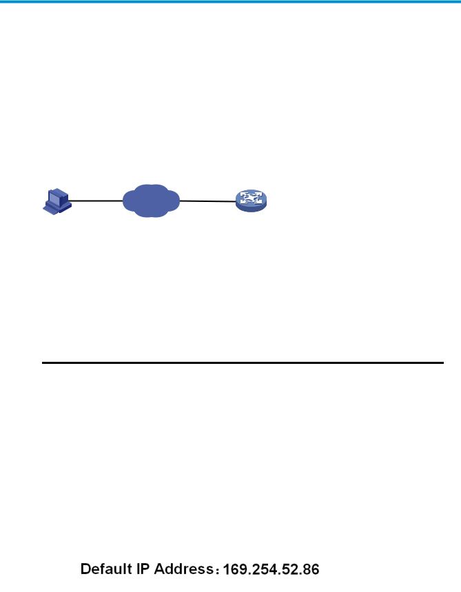
Configuration through the web interface
Web-based network management operating environment
HP provides the web-based network management function to facilitate the operations and maintenance on HP’s network devices. Through this function, the administrator can visually manage and maintain network devices through the web-based configuration interfaces.
a.Web-based network management operating environment
Logging in to the web interface
Default login information
The device is provided with the default Web login information. You can use the default information to log in to the web interface.
1.The default web login information
|
Information needed at login |
Default value |
|
|
Username |
admin |
|
|
Password |
None |
|
|
IP address of the device (VLAN-interface 1) |
Default IP address of the device, depending on the status |
|
|
of the network where the device resides. |
||
Table 1 The device is not connected to the network, or no DHCP server exists in the subnet where the device resides
If the device is not connected to the network, or no DHCP server exists in the subnet where the device resides, you can get the default IP address of the device on the label on the device, as shown in b. The default subnet mask is 255.255.0.0.
b.Default IP address of the device
2
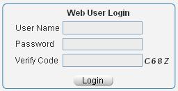
Table 2 A DHCP server exists in the subnet where the device resides
If a DHCP server exists in the subnet where the device resides, the device will dynamically obtain its default IP address through the DHCP server. You can log in to the device through the console port, and execute the summary command to view the information of its default IP address.
|
<Sysname> summary |
|
|
Select menu option: |
Summary |
|
IP Method: |
DHCP |
|
IP address: |
10.153.96.86 |
|
Subnet mask: |
255.255.255.0 |
|
Default gateway: |
0.0.0.0 |
|
<Omitted> |
Example
Assuming that the default IP address of the device is 169.254.52.86, follow these steps to log in to the device through the web interface.
Connect the device to a PC
Connect the GigabitEthernet interface of the device to a PC by using a crossover Ethernet cable (by default, all interfaces belong to VLAN 1).
Configure an IP address for the PC and ensure that the PC and device can communicate with each other properly.
Select an IP address for the PC from network segment 169.254.0.0/16 (except for the default IP address of the device), for example, 169.254.52.86.
Open the browser, and input the login information.
On the PC, open the browser (IE 5.0 or later), type the IP address http://169.254.52.86 in the address bar, and press Enter to enter the login page of the web interface, as shown in a. Input the username admin and verification code, leave the password blank, and click Login.
a.Login page of the web interface
3
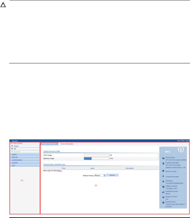
CAUTION:
The PC where you configure the device is not necessarily a web-based network management terminal. A web-based network management terminal is a PC used to log in to the web interface and is required to be reachable to the device.
After logging in to the web interface, you can select Device Users from the navigation tree, create a new user, and select Wizard or Network VLAN interface to configure the IP address of the VLAN interface acting as the management interface. For more information, see the corresponding configuration guides of these modules.
If you click the verification code displayed on the web login page, you can get a new verification code.
Up to five users can concurrently log in to the device through the web interface.
Logging out of the web interface
Click Logout in the upper-right corner of the web interface, as shown in a to quit the web console.
The system does not save the current configuration automatically. Therefore, it is recommended to save the current configuration before logout.
Introduction to the web interface
The Web interface is composed of three parts: navigation tree, title area, and body area, as shown in a.
a.Web-based configuration interface
|
(1) Navigation tree |
(2) Body area |
(3) Title area |
Navigation tree—Organizes the web-based NM functions as a navigation tree, where you can select and configure functions as needed. The result is displayed in the body area.
Body area—Allows you to configure and display features.
Title area—Displays the path of the current configuration interface in the navigation tree; provides the Help button to display the web related help information, and the Logout button to log out of the web interface.
4

CAUTION:
The web network management functions not supported by the device are not displayed in the navigation tree.
Web user level
Web user levels, from low to high, are visitor, monitor, configure, and management. A user with a higher level has all the operating rights of a user with a lower level.
Visitor—Users of this level can only use the network diagnostic tools ping and Trace Route. They can neither access the device data nor configure the device.
Monitor—Users of this level can only access the device data but cannot configure the device.
Configure—Users of this level can access device data and configure the device, but they cannot upgrade the host software, add/delete/modify users, or back up/restore configuration files.
Management—Users of this level can perform any operations to the device.
Introduction to the web-based NM functions
NOTE:
User level in 1 indicates that users of this level or users of a higher level can perform the corresponding operations.
1.Description of Web-based NM functions
|
Function menu |
Description |
User level |
|||
|
Wizard |
IP Setup |
Allows you to perform quick configuration of the |
Management |
||
|
device. |
|||||
|
Displays global settings and port settings of a |
Configure |
||||
|
stack. |
|||||
|
Setup |
|||||
|
Allows you to configure global parameters and |
Management |
||||
|
stack ports. |
|||||
|
IRF |
|||||
|
Topology |
Displays the topology summary of a stack. |
Configure |
|||
|
Summary |
|||||
|
Device |
Displays the control panels of stack members. |
Configure |
|||
|
Summary |
|||||
|
System |
Displays the basic system information, system |
Monitor |
|||
|
Information |
resource state, and recent system operation logs. |
||||
|
Summary |
|||||
|
Device |
Displays the port information of the device. |
Monitor |
|||
|
Information |
|||||
|
System Name |
Displays and allows you to configure the system |
Configure |
|||
|
Devi |
name. |
||||
|
Basic |
|||||
|
ce |
Web Idle |
Displays and allows you to configure the idle |
Configure |
||
|
Timeout |
timeout period for logged-in users. |
||||
5

|
Function menu |
Description |
User level |
|||
|
Software |
Allows you to configure to upload upgrade file |
Management |
|||
|
Upgrade |
from local host, and upgrade the system software. |
||||
|
Device |
|||||
|
Reboot |
Allows you to configure to reboot the device. |
Management |
|||
|
Maintenan |
|||||
|
Electronic Label |
Displays the electronic label of the device. |
Monitor |
|||
|
ce |
|||||
|
Diagnostic |
Generates diagnostic information file, and allows |
Management |
|||
|
Information |
you to view or save the file to local host. |
||||
|
System |
System Time |
Displays and allows you to configure the system |
Configure |
||
|
Time |
date and time. |
||||
|
Loglist |
Displays and refreshes system logs. |
Monitor |
|||
|
Allows you to clear system logs. |
Configure |
||||
|
Syslog |
|||||
|
Loghost |
Displays and allows you to configure the loghost. |
Configure |
|||
|
Log Setup |
Displays and allows you to configure the buffer |
Configure |
|||
|
capacity, and interval for refreshing system logs. |
|||||
|
Allows you to back up the configuration file to be |
|||||
|
Backup |
used at the next startup from the device to the host |
Management |
|||
|
of the current user. |
|||||
|
Configurati |
Allows you to upload the configuration file to be |
||||
|
Restore |
used at the next startup from the host of the current |
Management |
|||
|
on |
user to the device. |
||||
|
Save |
Allows you to save the current configuration to the |
Configure |
|||
|
configuration file to be used at the next startup. |
|||||
|
Initialize |
Allows you to restore the factory default settings. |
Configure |
|||
|
File |
File |
Allows you to manage files on the device, such as |
|||
|
Managem |
displaying the file list, downloading a file, |
Management |
|||
|
Management |
|||||
|
ent |
uploading a file, and removing a file. |
||||
|
Summary |
Displays port information by features. |
Monitor |
|||
|
Port |
|||||
|
Detail |
Displays feature information by ports. |
Monitor |
|||
|
Managem |
|||||
|
ent |
Setup |
Allows you to create, modify, delete, and |
Configure |
||
|
enable/disable a port, and clear port statistics. |
|||||
|
Summary |
Displays the configuration information of a port |
Monitor |
|||
|
mirroring group. |
|||||
|
Port |
Create |
Allows you to create a port mirroring group. |
Configure |
||
|
Mirroring |
Remove |
Allows you to remove a port mirroring group. |
Configure |
||
|
Modify Port |
Allows you to configure ports for a mirroring |
Configure |
|||
|
group. |
|||||
|
Summary |
Displays the brief information of FTP and Telnet |
Monitor |
|||
|
users. |
|||||
|
Users |
Allows you to configure a password for a |
||||
|
Super Password |
lower-level user to switch from the current access |
Management |
|||
|
level to the management level. |
|||||
|
Create |
Allows you to create an FTP or Telnet user. |
Management |
|||
6

|
Function menu |
Description |
User level |
||
|
Modify |
Allows you to modify FTP or Telnet user |
Management |
||
|
information. |
||||
|
Remove |
Allows you to remove an FTP or a Telnet user. |
Management |
||
|
Switch To |
Allows you to switch the current user level to the |
Visitor |
||
|
Management |
management level. |
|||
|
Loopback |
Loopback |
Allows you to perform loopback tests on Ethernet |
Configure |
|
|
interfaces. |
||||
|
VCT |
VCT |
Allows you to check the status of the cables |
Configure |
|
|
connected to Ethernet ports. |
||||
|
Port Traffic |
Displays the average rate at which the interface |
|||
|
receives and sends packets within a specified time |
Monitor |
|||
|
Flow |
Statistics |
|||
|
interval. |
||||
|
Interval |
||||
|
Interval |
Allows you to set an interval for collecting traffic |
Configure |
||
|
Configuration |
statistics on interfaces. |
|||
|
Displays and allows you to set the interval for |
||||
|
Storm |
Storm Constrain |
collecting storm constrain statistics. |
Configure |
|
|
Constrain |
Displays, and allows you to create, modify, and |
|||
|
remove the port traffic threshold. |
||||
|
Statistics |
Displays, and allows you to create, modify, and |
Configure |
||
|
clear RMON statistics. |
||||
|
History |
Displays, and allows you to create, modify, and |
Configure |
||
|
clear RMON history sampling information. |
||||
|
RMON |
Alarm |
Allows you to view, create, modify, and clear |
Configure |
|
|
alarm entries. |
||||
|
Event |
Allows you to view, create, modify, and clear event |
Configure |
||
|
entries. |
||||
|
Log |
Displays log information about RMON events. |
Configure |
||
|
Energy |
Energy Saving |
Displays and allows you to configure the energy |
Configure |
|
|
Saving |
saving settings of an interface. |
|||
|
Displays and refreshes SNMP configuration and |
Monitor |
|||
|
Setup |
statistics information. |
|||
|
Allows you to configure SNMP. |
Configure |
|||
|
Displays SNMP community information. |
Monitor |
|||
|
Community |
||||
|
Allows you to create, modify and delete an SNMP |
Configure |
|||
|
community. |
||||
|
SNMP |
||||
|
Displays SNMP group information. |
Monitor |
|||
|
Group |
||||
|
Allows you to create, modify and delete an SNMP |
Configure |
|||
|
group. |
||||
|
Displays SNMP user information. |
Monitor |
|||
|
User |
||||
|
Allows you to create, modify and delete an SNMP |
Configure |
|||
|
user. |
||||
7

|
Function menu |
Description |
User level |
|||
|
Displays the status of the SNMP trap function and |
Monitor |
||||
|
information about target hosts. |
|||||
|
Trap |
|||||
|
Allows you to enable or disable the SNMP trap |
Configure |
||||
|
function, or create, modify and delete a target host. |
|||||
|
Displays SNMP view information. |
Monitor |
||||
|
View |
|||||
|
Allows you to create, modify and delete an SNMP |
Configure |
||||
|
view. |
|||||
|
Interface |
Interface |
Displays and allows you to clear the statistics |
Configure |
||
|
Statistics |
Statistics |
information of an interface. |
|||
|
Select VLAN |
Allows you to select a VLAN range. |
Monitor |
|||
|
Create |
Allows you to create VLANs. |
Configure |
|||
|
Port Detail |
Displays the VLAN-related details of a port. |
Monitor |
|||
|
Detail |
Displays the member port information of a VLAN. |
Monitor |
|||
|
VLAN |
|||||
|
Modify VLAN |
Allows you to modify the description and member |
Configure |
|||
|
ports of a VLAN. |
|||||
|
Modify Port |
Allows you to change the VLAN to which a port |
Configure |
|||
|
belongs. |
|||||
|
Remove |
Allows you to remove VLANs. |
Configure |
|||
|
Summary |
Displays information about VLAN interfaces by |
Monitor |
|||
|
address type. |
|||||
|
VLAN |
Create |
Allows you to create VLAN interfaces and |
Configure |
||
|
configure IP addresses for them. |
|||||
|
Interface |
|||||
|
Modify |
Allows you to modify the IP addresses and status of |
Configure |
|||
|
VLAN interfaces. |
|||||
|
Net |
|||||
|
Remove |
Allows you to remove VLAN interfaces. |
Configure |
|||
|
work |
|||||
|
Summary |
Displays voice VLAN information globally or on a |
Monitor |
|||
|
port. |
|||||
|
Setup |
Allows you to configure the global voice VLAN. |
Configure |
|||
|
Port Setup |
Allows you to configure a voice VLAN on a port. |
Configure |
|||
|
Voice |
|||||
|
OUI Summary |
Displays the addresses of the OUIs that can be |
Monitor |
|||
|
VLAN |
|||||
|
identified by voice VLAN. |
|||||
|
OUI Add |
Allows you to add the address of an OUI that can |
Configure |
|||
|
be identified by voice VLAN. |
|||||
|
OUI Remove |
Allows you to remove the address of an OUI that |
Configure |
|||
|
can be identified by voice VLAN. |
|||||
|
MAC |
Displays MAC address information. |
Monitor |
|||
|
MAC |
Allows you to create and remove MAC addresses. |
Configure |
|||
|
Setup |
Displays and allows you to configure MAC address |
Configure |
|||
|
aging time. |
|||||
|
MSTP |
Region |
Displays information about MST regions. |
Monitor |
||
8
![]()
|
Function menu |
Description |
User level |
||
|
Allows you to modify MST regions. |
Configure |
|||
|
Global |
Allows you to set global MSTP parameters. |
Configure |
||
|
Port Summary |
Displays the MSTP information of ports. |
Monitor |
||
|
Port Setup |
Allows you to set MSTP parameters on ports. |
Configure |
||
|
Summary |
Displays information about link aggregation |
Monitor |
||
|
groups. |
||||
|
Link |
||||
|
Create |
Allows you to create link aggregation groups. |
Configure |
||
|
Aggregati |
||||
|
on |
Modify |
Allows you to modify link aggregation groups. |
Configure |
|
|
Remove |
Allows you to remove link aggregation groups. |
Configure |
||
|
Summary |
Displays information about LACP-enabled ports |
Monitor |
||
|
LACP |
and their partner ports. |
|||
|
Setup |
Allows you to set LACP priorities. |
Configure |
||
|
Displays the LLDP configuration information, local |
||||
|
Port Setup |
information, neighbor information, statistics |
Monitor |
||
|
information, and status information of a port. |
||||
|
Allows you to modify LLDP configuration on a port. Configure |
||||
|
LLDP |
Global Setup |
Displays global LLDP configuration information. |
Monitor |
|
|
Allows you to configure global LLDP parameters. |
Configure |
|||
|
Global |
Displays global LLDP local information and |
Monitor |
||
|
Summary |
statistics. |
|||
|
Neighbor |
Displays global LLDP neighbor information. |
Monitor |
||
|
Summary |
||||
|
Displays global IGMP snooping configuration |
||||
|
information or the IGMP snooping configuration |
Monitor |
|||
|
information in a VLAN, and allows you to view the |
||||
|
Basic |
||||
|
IGMP snooping multicast entry information. |
||||
|
IGMP |
||||
|
Allows you to configure IGMP snooping globally or |
Configure |
|||
|
Snooping |
in a VLAN. |
|||
|
Displays the IGMP snooping configuration |
Monitor |
|||
|
Advanced |
information on a port. |
|||
|
Allows you to configure IGMP snooping on a port. Configure |
||||
|
Summary |
Displays the IPv4 active route table. |
Monitor |
||
|
IPv4 |
||||
|
Create |
Allows you to create an IPv4 static route. |
Configure |
||
|
Routing |
||||
|
Remove |
Allows you to delete the selected IPv4 static routes. |
Configure |
||
|
Displays information about the DHCP status, |
||||
|
advanced configuration information of the DHCP |
||||
|
DHCP |
DHCP Relay |
relay agent, DHCP server group configuration, |
Monitor |
|
|
DHCP relay agent interface configuration, and the |
||||
|
DHCP client information. |
||||
9

|
Function menu |
Description |
User level |
|
Allows you to enable/disable DHCP, configure |
||
|
advanced DHCP relay agent settings, configure a |
Configure |
|
|
DHCP server group, and enable/disable the DHCP |
||
|
relay agent on an interface. |
||
|
Displays the status, trusted and untrusted ports and |
Monitor |
|
|
DHCP client information of DHCP snooping. |
||
|
Allows you to enable/disable DHCP snooping, |
||
|
and configure DHCP snooping trusted and |
Configure |
|
|
untrusted ports. |
|
Displays the states of services: enabled or |
Configure |
||||
|
disabled. |
|||||
|
Service |
Service |
||||
|
Allows you to enable/disable services, and set |
Management |
||||
|
related parameters. |
|||||
|
Diagnostic |
Ping |
Allows you to ping an IPv4 address. |
Visitor |
||
|
Tools |
Trace Route |
Allows you to perform trace route operations. |
Visitor |
||
|
Displays ARP table information. |
Monitor |
||||
|
ARP Table |
|||||
|
Allows you to add, modify, and remove ARP |
Configure |
||||
|
ARP |
|||||
|
entries. |
|||||
|
Managem |
|||||
|
Displays the configuration information of gratuitous |
|||||
|
ent |
Monitor |
||||
|
Gratuitous ARP |
ARP. |
||||
|
Allows you to configure gratuitous ARP. |
Configure |
||||
|
ARP |
ARP Detection |
Displays ARP detection configuration information. |
Monitor |
||
|
Anti-Attack |
Allows you to configure ARP detection. |
Configure |
|||
|
Displays 802.1X configuration information |
Monitor |
||||
|
globally or on a port. |
|||||
|
802.1X |
802.1X |
||||
|
Allows you to configure 802.1X globally or on a |
Configure |
||||
|
port. |
|||||
|
Domain Setup |
Displays ISP domain configuration information. |
Monitor |
|||
|
Allows you to add and remove ISP domains. |
Management |
||||
|
Auth |
Displays the authentication configuration |
Monitor |
|||
|
information of an ISP domain. |
|||||
|
entic |
Authentication |
||||
|
ation |
Allows you to specify authentication methods for an |
||||
|
Management |
|||||
|
ISP domain. |
|||||
|
AAA |
|||||
|
Displays the authorization method configuration |
Monitor |
||||
|
information of an ISP domain. |
|||||
|
Authorization |
|||||
|
Allows you to specify authorization methods for an |
Management |
||||
|
ISP domain. |
|||||
|
Accounting |
Displays the accounting method configuration |
Monitor |
|||
|
information of an ISP domain. |
|||||
10

|
Function menu |
Description |
User level |
|||
|
Allows you to specify accounting methods for an |
Management |
||||
|
ISP domain. |
|||||
|
RADIUS Server |
Displays and allows you to configure RADIUS |
Management |
|||
|
server information. |
|||||
|
RADIUS |
|||||
|
RADIUS Setup |
Displays and allows you to configure RADIUS |
Management |
|||
|
parameters. |
|||||
|
Displays configuration information about local |
Monitor |
||||
|
users. |
|||||
|
Local User |
|||||
|
Allows you to create, modify and remove a local |
Management |
||||
|
user. |
|||||
|
Users |
|||||
|
Displays configuration information about user |
Monitor |
||||
|
groups. |
|||||
|
User Group |
|||||
|
Allows you to create, modify and remove a user |
Management |
||||
|
group. |
|||||
|
Entity |
Displays information about PKI entities. |
Monitor |
|||
|
Allows you to add, modify, and delete a PKI entity. |
Configure |
||||
|
Displays information about PKI domains. |
Monitor |
||||
|
Domain |
|||||
|
Allows you to add, modify, and delete a PKI |
Configure |
||||
|
domain. |
|||||
|
PKI |
Displays the certificate information of PKI domains |
Monitor |
|||
|
and allows you to view the contents of a certificate. |
|||||
|
Certificate |
Allows you to generate a key pair, destroy a key |
||||
|
pair, retrieve a certificate, request a certificate, and |
Configure |
||||
|
delete a certificate. |
|||||
|
CRL |
Displays the contents of the CRL. |
Monitor |
|||
|
Allows you to receive the CRL of a domain. |
Configure |
||||
|
Port Isolate |
Summary |
Displays port isolation group information. |
Monitor |
||
|
Group |
Modify |
Allows you to configure a port isolation group. |
Configure |
||
|
Secu |
|||||
|
Displays the configurations of authorized IP, the |
|||||
|
rity |
|||||
|
Authorized |
Summary |
associated IPv4 ACL list, and the associated IPv6 |
Management |
||
|
ACL list. |
|||||
|
IP |
|||||
|
Setup |
Allows you to configure authorized IP. |
Management |
|||
|
Summary |
Displays time range configuration information. |
Monitor |
|||
|
Time |
|||||
|
Create |
Allows you to create a time range. |
Configure |
|||
|
Range |
|||||
|
Remove |
Allows you to delete a time range. |
Configure |
|||
|
QoS |
Summary |
Displays IPv4 ACL configuration information. |
Monitor |
||
|
Create |
Allows you to create an IPv4 ACL. |
Configure |
|||
|
ACL IPv4 |
|||||
|
Basic Setup |
Allows you to configure a rule for a basic IPv4 ACL. |
Configure |
|||
|
Advanced |
Allows you to configure a rule for an advanced |
Configure |
|||
|
Setup |
IPv4 ACL. |
||||
11

|
Function menu |
Description |
User level |
|||
|
Link Setup |
Allows you to create a rule for a link layer ACL. |
Configure |
|||
|
Remove |
Allows you to delete an IPv4 ACL or its rules. |
Configure |
|||
|
Queue |
Summary |
Displays the queue information of a port. |
Monitor |
||
|
Setup |
Allows you to configure a queue on a port. |
Configure |
|||
|
Line Rate |
Summary |
Displays line rate configuration information. |
Monitor |
||
|
Setup |
Allows you to configure the line rate. |
Configure |
|||
|
Summary |
Displays classifier configuration information. |
Monitor |
|||
|
Create |
Allows you to create a class. |
Configure |
|||
|
Classifier |
Setup |
Allows you to configure the classification rules for a |
Configure |
||
|
class. |
|||||
|
Remove |
Allows you to delete a class or its classification |
Configure |
|||
|
rules. |
|||||
|
Summary |
Displays traffic behavior configuration information. |
Monitor |
|||
|
Create |
Allows you to create a traffic behavior. |
Configure |
|||
|
Setup |
Allows you to configure actions for a traffic |
Configure |
|||
|
Behavior |
behavior. |
||||
|
Port Setup |
Allows you to configure traffic mirroring and traffic |
Configure |
|||
|
redirecting for a traffic behavior |
|||||
|
Remove |
Allows you to delete a traffic behavior. |
Configure |
|||
|
Summary |
Displays QoS policy configuration information. |
Monitor |
|||
|
Create |
Allows you to create a QoS policy. |
Configure |
|||
|
QoS Policy |
Setup |
Allows you to configure the classifier-behavior |
Configure |
||
|
associations for a QoS policy. |
|||||
|
Remove |
Allows you to delete a QoS policy or its |
Configure |
|||
|
classifier-behavior associations. |
|||||
|
Summary |
Displays the QoS policy applied to a port. |
Monitor |
|||
|
Port Policy |
Setup |
Allows you to apply a QoS policy to a port. |
Configure |
||
|
Remove |
Allows you to remove the QoS policy from the port. |
Configure |
|||
|
Priority |
Priority |
Displays priority mapping table information. |
Monitor |
||
|
Mapping |
Mapping |
Allows you to modify the priority mapping entries. |
Configure |
||
|
Port Priority |
Port Priority |
Displays port priority and trust mode information. |
Monitor |
||
|
Allows you to modify port priority and trust mode. |
Configure |
||||
|
Summary |
Displays PSE information and PoE interface |
Monitor |
|||
|
PoE |
PoE |
information. |
|||
|
Setup |
Allows you to configure a PoE interface. |
Configure |
|||
12
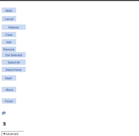
Introduction to the common items on the web pages
Buttons and icons
1.Commonly used buttons and icons
|
Button and icon |
Function |
||
|
Used to apply the configuration on the current page. |
|||
|
Used to cancel the configuration on the current page, and return to the |
|||
|
corresponding list page or the Device Info page. |
|||
|
Used to refresh the information on the current page. |
|||
|
Used to clear all the information on a list or all statistics. |
|||
|
Used to enter a page for adding an item. |
|||
|
, |
Used to remove the selected items. |
||
|
Used to select all the entries on a list, or all the ports on the device panel. |
|||
|
Used to deselect all the entries on a list, or all the ports on the device panel. |
|||
|
Generally present on the configuration wizard; used to buffer but not apply |
|||
|
the configuration of the current step and enter the next configuration step. |
|||
|
Generally present on the configuration wizard; used to buffer but not apply |
|||
|
the configuration of the current step and return to the previous configuration |
|||
|
step. |
|||
|
Generally present on the configuration wizard; used to apply the |
|||
|
configurations of all configuration steps. |
|||
|
Generally present on the “Operation” column on a list; used to enter the |
|||
|
modification page of an item so that you can modify the configurations of |
|||
|
the item. |
|||
|
Generally present on the “Operation” column on a list; used to delete the |
|||
|
item corresponding to this icon. |
|||
|
Click the plus sign before a corresponding item. You can see the collapsed |
|||
|
contents. |
|||
Page display
The web interface can display a long list by pages, as shown in a. You can set the number of entries displayed per page, and use the First, Prev, Next, and Last links to view the contents on the first, previous, next, and last pages, or go to any page that you want to view.
13

a.Content display by pages
Search function
On some list pages, the web interface provides basic and advanced search functions. You can use the search function to display those entries matching certain search criteria.
Basic search function—Select a search item from the drop-down list as shown in a, input the keyword, and click the Query button to display the entries that match the criteria.
Advanced search function—Click  before Search Item, as shown in a. You can select Match case and whole word, that is, the item to be searched must completely match the keyword, or you can select Search in previous results. If you do not select exact search, a fuzzy search is performed.
a.Advanced search
Sorting function
On some list pages, the web interface provides the sorting function to display the entries in a certain order.
As shown in a, you can click the blue heading item of each column to sort the entries based on the heading item you selected. Then, the heading item is displayed with an arrow beside it. The upward arrow indicates the ascending order, and the downward arrow indicates the descending order.
14

a.Sort display (based on MAC address in the ascending order)
Configuration guidelines
The web console supports Microsoft Internet Explorer 6.0 SP2 and higher.
The web console does not support the Back, Next, Refresh buttons provided by the browser. Using these buttons may result in abnormal display of web pages.
When the device is performing the spanning tree calculation, you cannot log in to or use the web interface.
The Windows firewall limits the number of TCP connections, so when you use IE to log in to the web interface, sometimes you may be unable to open the web interface. To avoid this problem, turn off the Windows firewall before login.
If the software version of the device changes, when you log in to the device through the web interface, delete the temporary Internet files of IE; otherwise, the web page content may not be displayed correctly.
15

Configuration at the CLI
NOTE:
The HP V1910 Switch Series can be configured through the CLI, web interface, and SNMP/MIB, among which the web interface supports all V1910 Switch Series configurations. These configuration methods are suitable for different application scenarios. As a supplementary to the web interface, the CLI provides some configuration commands to facilitate your operation, which are described in this chapter. To perform other configurations not supported by the CLI, use the web interface.
You will enter user view directly after you log in to the device. Commands in the document are all performed in user view.
Getting started with the CLI
As a supplementary to the web interface, the CLI provides some configuration commands to facilitate your operation. For example, if you forget the IP address of VLAN-interface 1 and cannot log in to the device through the web interface, you can connect the console port of the device to a PC, and reconfigure the IP address of VLAN-interface 1 at the CLI.
This section describes using the CLI to manage the device.
Setting up the configuration environment
To set up the configuration environment, connect a terminal (a PC in this example) to the console port on the switch with a console cable.
A console cable is an 8-core shielded cable, with a crimped RJ-45 connector at one end for connecting to the console port of the switch, and a DB-9 female connector at the other end for connecting to the serial port on the console terminal.
a.Console cable
Use  a console cable to connect a terminal device to the switch, as follows:
Table 3 Plug the DB-9 female connector to the serial port of the console terminal or PC. Table 4 Connect the RJ-45 connector to the console port of the switch.
16
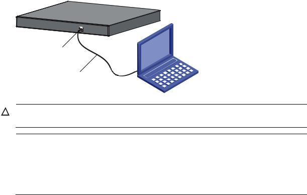
b.Network diagram for configuration environment setup
CAUTION:
Verify the mark on the console port to ensure that you are connecting to the correct port.
NOTE:
The serial port on a PC does not support hot swapping. When you connect a PC to a powered-on switch, connect the DB-9 connector of the console cable to the PC before connecting the RJ-45 connector to the switch.
When you disconnect a PC from a powered-on switch, disconnect the DB-9 connector of the console cable from the PC after disconnecting the RJ-45 connector from the switch.
Setting terminal parameters
To configure and manage the switch, you must run a terminal emulator program on the console terminal, for example, a PC. This section uses Windows XP HyperTerminal as an example.
The following are the required terminal settings:
Bits per second—38400
Data bits—8
Parity—None
Stop bits—1
Flow control—None
Emulation—VT100
Follow these steps to set terminal parameters, for example, on a Windows XP HyperTerminal:
Table 5 Select Start All Programs Accessories Communications HyperTerminal, and in the
Connection Description dialog box that appears, type the name of the new connection in the Name text box and click OK.
17
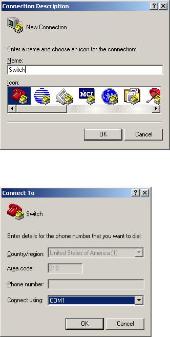
b.Connection description of the HyperTerminal
Table 6 Select the serial port to be used from the Connect using drop-down list, and click OK.
c.Set the serial port used by the HyperTerminal connection
Table 7 Set Bits per second to 38400, Data bits to 8, Parity to None, Stop bits to 1, and Flow control to
None, and click OK.
18
![]()
d.Set the serial port parameters
Table 8 Select File Properties in the HyperTerminal window.
e.HyperTerminal window
19

Table 9 Click the Settings tab, set the emulation to VT100, and click OK in the Switch Properties dialog box.
f.Set terminal emulation in Switch Properties dialog box
Logging in to the CLI
The login process requires a username and password. The default username for first time configuration is admin, no password is required. Usernames and passwords are case sensitive.
To log in to the CLI:
Table 10 Press Enter. The Username prompt displays:
Login authentication
Username:
Table 11 Enter your username at the Username prompt.
Username:admin
Table 12 Press Enter. The Password prompt display
Password:
The login information is verified, and displays the following CLI menu:
<HP V1910 Switch>
If the password is invalid, the following message appears and process restarts.
% Login failed!
20

CLI commands
This Command section contains the following commands:
|
To do… |
Use the command… |
|
|
Display a list of CLI commands on the device |
? |
|
|
Reboot the device and run the default configuration |
initialize |
|
|
Specify VLAN-interface 1 to obtain an IP address through |
ipsetup { dhcp | ip address ip-address { mask |
|
|
| mask-length } [ default-gateway |
||
|
DHCP or manual configuration |
||
|
ip-address ] } |
||
|
Modify the login password of a user |
password |
|
|
Download the Boot ROM image or system software image file |
upgrade server-address source-filename |
|
|
from the TFTP server and specify as the startup configuration |
||
|
{ bootrom | runtime } |
||
|
file |
||
|
Reboot the device and run the main configuration file |
reboot |
|
|
View the summary information of the device |
summary |
|
|
Ping a specified destination |
ping host |
|
initialize
Syntax
initialize
Parameters
None
Description
Use the initialize command to delete the current configuration file and reboot the device with the default configuration file.
Use the command with caution because it deletes the configuration file to be used at the next startup and restores the factory default settings.
Examples
# Delete the configuration file to be used at the next startup and reboot the device with the default configuration being used during reboot.
<Sysname> initialize
The startup configuration file will be deleted and the system will be rebooted.Continue? [Y/N]:y
Please wait…
ipsetup
Syntax
ipsetup { dhcp | ip address ip-address { mask | mask-length } [ default-gateway ip-address ] }
21
Parameters
dhcp: Specifies the interface to obtain an IP address through DHCP.
ip-address ip-address: Specifies an IP address for VLAN-interface 1 in dotted decimal notation. mask: Subnet mask in dotted decimal notation.
mask-length: Subnet mask length, the number of consecutive ones in the mask, in the range of 0 to 32.
default-gateway ip-address: Specifies the IP address of the default gateway or the IP address of the outbound interface. With this argument and keyword combination configured, the command not only assigns an IP address to the interface, but also specifies a default route for the device.
Description
Use the ipsetup dhcp command to specify VLAN-interface 1 to obtain an IP address through DHCP.
Use the ipsetup ip address ip-address { mask | mask-length } command to assign an IP address to VLAN-interface 1.
By default, the device automatically obtains its IP address through DHCP; if fails, it uses the assigned default IP address. For more information, see b.
If there is no VLAN-interface 1, either command creates VLAN-interface 1 first, and then specifies its IP address.
Examples
# Create VLAN-interface 1 and specify the interface to obtain an IP address through DHCP.
<Sysname> ipsetup dhcp
# Create VLAN-interface 1 and assign 192.168.1.2 to the interface, and specify 192.168.1.1 as the default gateway.
<Sysname> ipsetup ip-address 192.168.1.2 24 default-gateway 192.168.1.1
password
Syntax
password
Parameters
None
Description
Use the password command to modify the login password of a user.
Examples
# Modify the login password of user admin.
<Sysname> password
Change password for user: admin Old password: ***
Enter new password: ** Retype password: **
The password has been successfully changed.
22
ping
Syntax
ping host
Parameters
host: Destination IP address (in dotted decimal notation), URL, or host name (a string of 1 to 20 characters).
Description
Use the ping command to ping a specified destination. You can enter Ctrl+C to terminate a ping operation.
Examples
# Ping IP address 1.1.2.2.
<Sysname> ping 1.1.2.2
PING 1.1.2.2: 56 data bytes, press CTRL_C to break
Reply from 1.1.2.2: bytes=56 Sequence=1 ttl=254 time=205 ms Reply from 1.1.2.2: bytes=56 Sequence=2 ttl=254 time=1 ms Reply from 1.1.2.2: bytes=56 Sequence=3 ttl=254 time=1 ms Reply from 1.1.2.2: bytes=56 Sequence=4 ttl=254 time=1 ms Reply from 1.1.2.2: bytes=56 Sequence=5 ttl=254 time=1 ms
— 1.1.2.2 ping statistics —
5 packet(s) transmitted
5 packet(s) received
0.00% packet loss
round-trip min/avg/max = 1/41/205 ms
The output shows that IP address 1.1.2.2 is reachable and the echo replies are all returned from the destination. The minimum, average, and maximum roundtrip intervals are 1 millisecond, 41 milliseconds, and 205 milliseconds respectively.
quit
Syntax
quit
Parameters
None
Description
Use the quit command to log out of the system.
Examples
# Log out of the system.
<Sysname> quit
******************************************************************************
|
* |
Copyright (c) 2004-2011 Hewlett-Packard Development Company, L.P. |
* |
|
* |
Without the owner’s prior written consent, |
* |
23
* no decompiling or reverse-engineering shall be allowed. *
******************************************************************************
User interface aux0 is available.
Please press ENTER.
reboot
Syntax
reboot
Parameters
None
Description
Use the reboot command to reboot the device and run the main configuration file. Use this command with caution because reboot results in service interruption.
If the main configuration file is corrupted or does not exist, the device cannot be rebooted with the reboot command. In this case, you can specify a new main configuration file to reboot the device, or you can power off the device, and then power it on, and the system will automatically use the backup configuration file at the next startup.
If you reboot the device when file operations are being performed, the system does not execute the command to ensure security.
Examples
# If the configuration does not change, reboot the device.
|
<Sysname> reboot |
|
|
Start to check configuration with next startup configuration file, please wait……… |
DONE! |
|
This command will reboot the device. Continue? [Y/N]:y |
|
|
Now rebooting, please wait… |
# If the configuration changes, reboot the device.
<Sysname> reboot
Start to check configuration with next startup configuration file, please wait………DONE!
This command will reboot the device. Current configuration will be lost in next startup if you continue. Continue? [Y/N]:y
Now rebooting, please wait…
summary
Syntax
summary
Parameters
None
24
Description
Use the summary command to view the summary information of the device, including the IP address of VLAN-interface 1, and software version information.
Examples
# Display summary information of the device.
|
<Sysname> summary |
|
|
Select menu option: |
Summary |
|
IP Method: |
DHCP |
|
IP address: |
10.153.96.86 |
|
Subnet mask: |
255.255.255.0 |
|
Default gateway: |
0.0.0.0 |
Current boot app is: flash:/v1910-cmw520-a1108.bin
Next main boot app is: flash:/v1910-cmw520-a1108.bin
Next backup boot app is: NULL
HP Comware Platform Software
Comware Software, Version 5.20 Alpha 1108,
Copyright (c) 2004-2011 Hewlett-Packard Development Company, L.P.
HP V1910-24G-PoE (365W) Switch uptime is 0 week, 0 day, 6 hours, 28 minutes
HP V1910-24G-PoE (365W) Switch 128M bytes DRAM
128M bytes Nand Flash Memory Config Register points to Nand Flash
Hardware Version is REV.B CPLD Version is 002 Bootrom Version is 138
[SubSlot 0] 24GE+4SFP+POE Hardware Version is REV.B
upgrade
Syntax
upgrade server-address source-filename { bootrom | runtime }
Parameters
server-address: IP address or host name (a string of 1 to 20 characters) of a TFTP server. source-filename: Software package name on the TFTP server.
bootrom: Specifies the Boot ROM image in the software package file as the startup configuration file.
runtime: Specifies the system software image file in the software package file as the startup configuration file.
25

Description
Use the upgrade server-address source-filename bootrom command to upgrade the Boot ROM image. If the Boot ROM image in the downloaded software package file is not applicable, the original Boot ROM image is still used as the startup configuration file.
Use the upgrade server-address source-filename runtime command to upgrade the system software image file. If the system software image file in the downloaded software package file is not applicable, the original system software image file is still used as the startup configuration file.
To make the downloaded software package file take effect, reboot the device.
NOTE:
The HP V1910 Switch Series does not provide an independent Boot ROM image; instead, it integrates the Boot ROM image with the system software image file together in a software package file with the extension name of .bin.
Examples
# Download software package file main.bin from the TFTP server and use the Boot ROM image in the package as the startup configuration file.
<Sysname> upgrade 192.168.20.41 main.bin bootrom
# Download software package file main.bin from the TFTP server and use the system software image file in the package as the startup configuration file.
<Sysname> upgrade 192.168.20.41 main.bin runtime
Configuration example for upgrading the system software image at the CLI
Network requirements
As shown in a, a V1910 switch is connected to the PC through the console cable, and connected to the gateway through GigabitEthernet 1/0/1. The IP address of the gateway is 192.168.1.1/24, and the TFTP server where the system software image (SwitchV1910.bin) is located is 192.168.10.1/24. The gateway and the switch can reach each other.
The administrator upgrades the Boot ROM image and the system software image file of the V1910 switch through the PC and sets the IP address of the switch to 192.168.1.2/24.
a.Network diagram for upgrading the system software image of the V1910 switch at the CLI
Configuration procedure
Table 13 Run the TFTP server program on the TFTP server, and specify the path of the file to be loaded. (Omitted)
Table 14 Perform the following configurations on the switch.
26
# Configure the IP address of VLAN-interface 1 of the switch as 192.168.1.2/24, and specify the default gateway as 192.168.1.1.
<Switch> ipsetup ip-address 192.168.1.2 24 default-gateway 192.168.1.1
# Download the software package file SwitchV1910.bin from the TFTP server to the switch, and upgrade the system software image in the package.
<Switch> upgrade 192.168.10.1 SwitchV1910.bin runtime File will be transferred in binary mode
Downloading file from remote TFTP server, please wait…/ TFTP: 10262144 bytes received in 71 second(s)
File downloaded successfully.
# Download the software package file SwitchV1910.bin from the TFTP server to the switch, and upgrade the Boot ROM image.
<Switch> upgrade 192.168.10.1 SwitchV1910.bin bootrom
The file flash:/SwitchV1910.bin exists. Overwrite it? [Y/N]:y Verifying server file…
Deleting the old file, please wait…
File will be transferred in binary mode
Downloading file from remote TFTP server, please wait…/ TFTP: 10262144 bytes received in 61 second(s)
File downloaded successfully. BootRom file updating finished!
# Reboot the switch.
<Switch> reboot
After getting the new image file, reboot the switch to have the upgraded image take effect.
27

Configuration wizard
Overview
The configuration wizard guides you through the basic service setup, including the system name, system location, contact information, and management IP address (IP address of the VLAN interface).
Basic service setup
Entering the configuration wizard homepage
From the navigation tree, select Wizard to enter the configuration wizard homepage, as shown in a.
a.Configuration wizard homepage
Configuring system parameters
In the wizard homepage, click Next to enter the system parameter configuration page, as shown in a.
28
![]()
a.System parameter configuration page
2.System parameter configuration items
|
Item |
Description |
|
Specify the system name. |
|
|
The system name appears at the top of the navigation tree. |
|
|
Sysname |
You can also set the system name in the System Name page you enter by selecting |
|
Device Basic. For more information, see the chapter “Device basic information |
|
|
configuration”. |
|
|
Specify the physical location of the system. |
|
|
Syslocation |
You can also set the physical location in the setup page you enter by selecting Device |
|
SNMP. For more information, see the chapter “SNMP configuration”. |
|
|
Set the contact information for users to get in touch with the device vendor for help. |
|
|
Syscontact |
You can also set the contact information in the setup page you enter by selecting Device |
|
SNMP. For more information, see the chapter “SNMP configuration”. |
|
Configuring management IP address
NOTE:
Modifying the management IP address used for the current login will tear down the connection to the device. Use the new management IP address to re-log in to the system.
29

A management IP address is the IP address of a VLAN interface, which can be used to access the device. You can also set configure a VLAN interface and its IP address in the page you enter by selecting Network VLAN Interface. For more information, see the chapter “VLAN interface configuration”.
After finishing the configuration, click Next to enter the management IP address configuration page, as shown in a.
a.Management IP address configuration page
2.Management IP address configuration items
|
Item |
Description |
||
|
Select a VLAN interface. |
|||
|
Select VLAN Interface |
Available VLAN interfaces are those configured in the page you enter by selecting |
||
|
Network VLAN Interface and selecting the Create tab. |
|||
|
Enable or disable the VLAN interface. |
|||
|
When errors occurred on the VLAN interface, disable the interface and then enable |
|||
|
the port to bring the port to work properly. |
|||
|
Admin Status |
By default, the VLAN interface is in the down state if all Ethernet ports in the VLAN are |
||
|
down. The VLAN is in the up state if one or more ports in the VLAN are up. |
|||
|
IMPORTANT: |
|||
|
Disabling or enabling the VLAN interface does not affect the status of the Ethernet ports |
|||
|
in the VLAN. That is, the port status does not change with the VLAN interface status. |
|||
|
Configure IPv4 |
DHCP |
Configure how the VLAN interface obtains an IPv4 address. |
|
|
address |
DHCP: Specifies the VLAN interface to obtain an IPv4 address by |
||
|
30 |

|
Item |
Description |
||
|
BOOTP |
DHCP. |
||
|
BOOTP: Specifies the VLAN interface to obtain an IPv4 address |
|||
|
through BOOTP. |
|||
|
Manual: Allows you to specify an IPv4 address and a mask length. |
|||
|
Manual |
IMPORTANT: |
||
|
Support for IPv4 obtaining methods depends on the device model. |
|||
|
IPv4 |
Specify an IPv4 address and the mask length for the VLAN interface. |
||
|
address |
|||
|
These two text boxes are configurable if Manual is selected. |
|||
|
MaskLen |
|||
Finishing configuration wizard
After finishing the management IP address configuration, click Next, as shown in a.
a.Configuration finishes
The page displays your configurations. Review the configurations and if you want to modify the settings click Back to go back to the page. Click Finish to confirm your settings and the system then performs the configurations.
31

IRF stack management
The HP V1910 IRF stack management feature enables you to configure and monitor a stack of connected HP V1910 switches by logging in to one switch in the stack, as shown in a.
IMPORTANT:
The HP V1910 IRF stack management feature does not provide the functions of HP Intelligent Resilient Framework (IRF) technology. To avoid confusion, IRF stack management is simply called stack management in this document.
a.Network diagram for stack management
To set up a stack, you must log in to one switch to create the stack, and this switch becomes the master for the stack. You then configure and monitor all other member switches on the master switch. The ports that connect the stack member switches are called stack ports.
Configuring stack management
Stack management configuration task list
Perform the tasks in 1 to configure stack management.
1.Stack management configuration task list
|
Configuring |
Configuring global |
|
|
the master |
||
|
parameters of a |
||
|
switch of a |
||
|
stack |
||
|
stack |
||
Required
Configure a private IP address pool for a stack and establish the stack, with the switch becoming the master switch of the stack.
By default, no IP address pool is configured for a stack and no stack is established.
32

|
Task |
Remarks |
||
|
Required |
|||
|
Configuring stack |
Configure the ports of the master switch that connect to member |
||
|
ports |
switches as stack ports. |
||
|
By default, a port is not a stack port. |
|||
|
Configuring |
Required |
||
|
member |
Configuring stack |
Configure a port of a member switch that connects to the master switch |
|
|
switches of a |
ports |
or another member switch as a stack port. |
|
|
stack |
By default, a port is not a stack port. |
||
|
Displaying topology summary of a |
Optional |
||
|
stack |
Display the information of stack members. |
||
|
Optional |
|||
|
Display the control panels of stack members. |
|||
|
Displaying device summary of a stack |
IMPORTANT: |
||
|
Before viewing the control panel of a member switch, you must ensure |
|||
|
that the username, password, and access right you used to log on to the |
|||
|
master switch are the same with those configured on the member switch; |
|||
|
otherwise, the control panel of the member switch cannot be displayed. |
|||
|
Optional |
|||
|
Log in to the web interface of a member switch from the master switch. |
|||
|
IMPORTANT: |
|||
|
Logging into a member switch from |
Before logging into a member switch, you must ensure that the |
||
|
the master switch |
username, password, and access right you used to log on to the master |
switch are the same with those configured on the member switch; otherwise, you cannot log into the member switch. You can configure them by selecting Device and then clicking Users from the navigation tree.
Configuring global parameters of a stack
Select IRF from the navigation tree to enter the page shown in a. You can configure global parameters of a stack in the Global Settings area.
33

a.Setup
2.Configuration items of global parameters
Configure a private IP address pool for the stack.
The master switch of a stack must be configured with a private IP address pool to ensure that it can automatically allocate an available IP address to a member switch when the device joints the stack.
 IMPORTANT:
When you configure a private IP address pool for a stack, the number of IP addresses in the address pool needs to be equal to or greater than the number of switches to be added to the stack. Otherwise, some switches may not be able to join the stack automatically for lack of private IP addresses.
34

|
Item |
Description |
|
Enable the switch to establish a stack. |
|
|
After you enable the switch to establish a stack, the switch becomes the master switch |
|
|
of the stack and automatically adds the switches connected to its stack ports to the |
|
|
Build Stack |
stack. |
|
IMPORTANT: |
|
|
You can delete a stack only on the master switch of the stack. The Global Settings area |
|
|
on a member switch is grayed out. |
Return to Stack management configuration task list.
Configuring stack ports
Select IRF from the navigation tree to enter the page shown in a. You can configure stack ports in the Port Settings area.
Select the check box before a port name, and click Enable to configure the port as a stack port.
Select the check box before a port name, and click Disable to configure the port as a non-stack port.
Return to Stack management configuration task list.
Displaying topology summary of a stack
Select IRF from the navigation tree and click the Topology Summary tab to enter the page shown in a.
a.Topology summary
2.Fields of topology summary
|
Fields |
Description |
|
|
Member ID of the device in the stack: |
||
|
Member ID |
Value 0 indicates that the switch is the master switch of the stack. |
|
|
A value other than 0 indicates that the switch is a member switch and the value |
||
|
is the member ID of the switch in the stack. |
||
|
Role |
Role of the switch in the stack: master or member. |
|
Return to Stack management configuration task list.
35

Displaying device summary of a stack
Select IRF from the navigation tree and click the Device Summary tab to enter the page shown in a. On this page, you can view interfaces and power socket layout on the panel of each stack member by clicking the tab of the corresponding member switch.
a.Device summary (the master switch)
Return to Stack management configuration task list.
Logging into a member switch from the master switch
Select IRF from the navigation tree, click the Device Summary tab, and click the tab of a member switch to enter the page shown in a.
Click the Configuring the Device hyperlink, you can log on to the web interface of the member switch to manage and maintain the member switch directly.
a.Device summary (a member switch)
Return to Stack management configuration task list.
Stack configuration example
Network requirements
As shown in a, Switch A, Switch B, Switch C, and Switch D are connected with one another.
36

Create a stack, where Switch A is the master switch, Switch B, Switch C, and Switch D are stack members. An administrator can log in to Switch B, Switch C and Switch D through Switch A to perform remote configurations.
a.Network diagram for stack management
|
Switch A |
|||
|
Eth1/0/1 |
(Master switch) |
||
|
Stack |
Eth1/0/2 |
||
|
Eth1/0/1 |
Eth1/0/3 |
||
|
Switch B |
|||
|
Eth1/0/1 |
Eth1/0/1 |
||
|
Switch C |
Switch D |
Configuration procedure
Table 15 Configure the master switch
# Configure global parameters for the stack on Switch A.
Select IRF from the navigation tree of Switch A to enter the page of the Setup tab.
37

b.Configure global parameters for the stack on Switch A
Type 192.168.1.1 in the text box of Private Net IP.
Type 255.255.255.0 in the text box of Mask.
Select Enable from the Build Stack drop-down list.
Click Apply.
Now, switch A becomes the master switch.
38
 Loading…