-
Contents
-
Table of Contents
-
Bookmarks
Quick Links
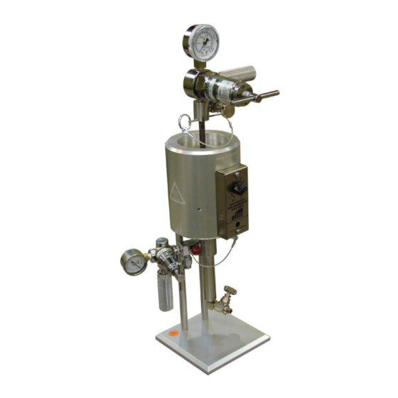
HTHP Filter Press for Ceramic Disks
with 175-mL, Double-Capped Test Cell and CO
Pressuring Assemblies
2
#170-00-7: (115 V)
#170-01-6: (230 V)
Instruction Manual
Updated 6/14/2019
Ver. 5
OFI Testing Equipment, Inc.
11302 Steeplecrest Dr. · Houston, Texas · 77065 · U.S.A.
Tele: 832.320.7300 · Fax: 713.880.9886 · www.ofite.com
Copyright OFITE 2015
©
Related Manuals for OfiTE 170-55
Summary of Contents for OfiTE 170-55
-
Page 1
175-mL, Double-Capped Test Cell and CO Pressuring Assemblies #170-00-7: (115 V) #170-01-6: (230 V) Instruction Manual Updated 6/14/2019 Ver. 5 OFI Testing Equipment, Inc. 11302 Steeplecrest Dr. · Houston, Texas · 77065 · U.S.A. Tele: 832.320.7300 · Fax: 713.880.9886 · www.ofite.com Copyright OFITE 2015 ©… -
Page 2: Table Of Contents
Safety ………………… 11 Diagram ………………19 Quick Start ………………20 Operation………………22 Data ………………..30 Maintenance ………………31 Appendix ………………35 Testing with Filter Paper …………35 Warranty and Return Policy …………36 OFITE, 11302 Steeplecrest Dr., Houston, TX 77065 USA / Tel: 832-320-7300 / Fax: 713-880-9886 / www.ofite.com…
-
Page 3: Intro
300°F (149°C). Anyone running tests above 350°F (177°C) must substitute a complete set of o-rings after each and every test. OFITE, 11302 Steeplecrest Dr., Houston, TX 77065 USA / Tel: 832-320-7300 / Fax: 713-880-9886 / www.ofite.com…
-
Page 4: Specifications
Two CO Pressuring Assemblies Test Cell Capacity: 175 mL Receiver Volume: 15 mL Power Requirement: #170-00-7: 115V; #170-01-6: 230V, 50/60 Hz Heater: 400 Watt OFITE, 11302 Steeplecrest Dr., Houston, TX 77065 USA / Tel: 832-320-7300 / Fax: 713-880-9886 / www.ofite.com…
-
Page 5: Components
Spacer for Filter Paper, ¼», 316 Stainless Steel #170-77-1 O-ring, 140 Viton 75D, for Spacer; Qty. 2 #171-21 Cell Cap with 60-mesh Screen, 2,000 psi OFITE, 11302 Steeplecrest Dr., Houston, TX 77065 USA / Tel: 832-320-7300 / Fax: 713-880-9886 / www.ofite.com…
-
Page 6
HTHP Cell Cap Puller #170-40: Test Cell Removal and Carrying Tool #170-91 HTHP Pressure Relief Tool #170-92 Safety Clamp for HTHP Fluid Loss Cells OFITE, 11302 Steeplecrest Dr., Houston, TX 77065 USA / Tel: 832-320-7300 / Fax: 713-880-9886 / www.ofite.com… -
Page 7
Everyone’s consumable requirements will be different, and replace- ment quantities needed will depend upon the number of test performed on a daily and/or weekly basis. OFITE, 11302 Steeplecrest Dr., Houston, TX 77065 USA / Tel: 832-320-7300 / Fax: 713-880-9886 / www.ofite.com… -
Page 8
HTHP Pressure Relief Tool Cell Carrying Tool (#170-40) (#170-91) (To release trapped pressure) Safety Clamp (#170-92) Safety Shield (#171-06) (Set Screw Cell Assemblies Only) OFITE, 11302 Steeplecrest Dr., Houston, TX 77065 USA / Tel: 832-320-7300 / Fax: 713-880-9886 / www.ofite.com… -
Page 9
Thermocouple Assembly High Pressure Nitrogen Assy. (#171-45-1) (#171-31) (Direct temperature measurement Of the fluid Inside the Cell) Stand for HTHP Cell Assembly (#171-190-028) OFITE, 11302 Steeplecrest Dr., Houston, TX 77065 USA / Tel: 832-320-7300 / Fax: 713-880-9886 / www.ofite.com… -
Page 10
Permeability is measure of the volume flow of fluids through a porous or semi porous media when subjected to a differential pressure. It is mathematically equated by Darcy’s Permeability Law. OFITE, 11302 Steeplecrest Dr., Houston, TX 77065 USA / Tel: 832-320-7300 / Fax: 713-880-9886 / www.ofite.com… -
Page 11
10 D #170-53-1 20 D 20 D #170-53-4 40 D 100 D #170-53-5 180 D #170-53-6 *1 Micron (µm) = 1/1,000 mm or 1/25,400 inch OFITE, 11302 Steeplecrest Dr., Houston, TX 77065 USA / Tel: 832-320-7300 / Fax: 713-880-9886 / www.ofite.com… -
Page 12: Safety
HTHP Filter Press and especially when one is going to extreme temperatures and pressures. Above 350°F (176°C) All o-rings must be replaced after each and every test. OFITE, 11302 Steeplecrest Dr., Houston, TX 77065 USA / Tel: 832-320-7300 / Fax: 713-880-9886 / www.ofite.com…
-
Page 13
The temperature of the fluid inside the cell however will not be at the set tem- perature, so always allow one hour of heating time for the fluid, after the cell has been fully inserted into the heating jacket. OFITE, 11302 Steeplecrest Dr., Houston, TX 77065 USA / Tel: 832-320-7300 / Fax: 713-880-9886 / www.ofite.com… -
Page 14
, but should never be used as a pressure source for HTHP Filtration. Under high temperatures and pressures, nitrous oxide can detonate in the presence of grease, oil or carbonaceous material. Bulbs, 10/Box, (#143-05) OFITE, 11302 Steeplecrest Dr., Houston, TX 77065 USA / Tel: 832-320-7300 / Fax: 713-880-9886 / www.ofite.com… -
Page 15
Viton o-rings is 400°F (204°C). OFITE suggests that all o-rings (cell caps, cell bodies, and valve stem) are changed each time after running a test of 350° F (176° C) or above. OFITE, 11302 Steeplecrest Dr., Houston, TX 77065 USA / Tel: 832-320-7300 / Fax: 713-880-9886 / www.ofite.com… -
Page 16
Some materials are more susceptible to corrosion than other. Also, some fluids and additives are more corrosive than others. OFITE offers a variety of cell materials for different levels of corrosion resistance and cost. OFITE, 11302 Steeplecrest Dr., Houston, TX 77065 USA / Tel: 832-320-7300 / Fax: 713-880-9886 / www.ofite.com… -
Page 17
9. Do not purge oxidizing or flammable gases in the presence of flame, lit cigarettes, or other sources of ignition or towards people. OFITE, 11302 Steeplecrest Dr., Houston, TX 77065 USA / Tel: 832-320-7300 / Fax: 713-880-9886 / www.ofite.com… -
Page 18
Cap Locking Cell Cap, Scribed Screws (#170-26-1) (#170-69) Valve Stem (#170-16) Cell Cap with Screen (#171-21) Valve Stem O-ring Cell Cap O-ring (#170-17) (#170-13-3) OFITE, 11302 Steeplecrest Dr., Houston, TX 77065 USA / Tel: 832-320-7300 / Fax: 713-880-9886 / www.ofite.com… -
Page 19
Needle Valve (#170-32) Retaining Pin (#171-23-1) With Lanyard Barrel for CO Bulb Manifold (#143-03) Block Needle Valve (#170-32) (#171-34) Pressuring Assembly Back Pressure Receiver (#170-04) (#170-06) OFITE, 11302 Steeplecrest Dr., Houston, TX 77065 USA / Tel: 832-320-7300 / Fax: 713-880-9886 / www.ofite.com… -
Page 20: Diagram
Receiver O-ring Barrel for CO Bulb (#170-07) (#143-03) (Not Shown) Safety Bleeder Valve (#143-06) Needle Valve 1⁄8 » 90 Street Ell (#170-32) (#144-11) (Not Shown) OFITE, 11302 Steeplecrest Dr., Houston, TX 77065 USA / Tel: 832-320-7300 / Fax: 713-880-9886 / www.ofite.com…
-
Page 21: Quick Start
Total heat up time should not to exceed 1 hour. 14. After the hour heat up time, increase pressure on inlet (top) pressure unit to 500 psi over the back pressure. OFITE, 11302 Steeplecrest Dr., Houston, TX 77065 USA / Tel: 832-320-7300 / Fax: 713-880-9886 / www.ofite.com…
-
Page 22
30. Inspect and replace any or all o-rings — All if test run > 300°F (149°C). 31. Report: Double the filtrate volume — Correct to the API standard of 7.1 in Spurt Loss volume is Optional. OFITE, 11302 Steeplecrest Dr., Houston, TX 77065 USA / Tel: 832-320-7300 / Fax: 713-880-9886 / www.ofite.com… -
Page 23: Operation
After tightening the cap locking screws, run your fingers around the cell body to ensure that all of the screws are tight and none are protruding from the wall. OFITE, 11302 Steeplecrest Dr., Houston, TX 77065 USA / Tel: 832-320-7300 / Fax: 713-880-9886 / www.ofite.com…
-
Page 24
If you need to test with filter paper, refer to page 35 for instructions on using the spacer. OFITE, 11302 Steeplecrest Dr., Houston, TX 77065 USA / Tel: 832-320-7300 / Fax: 713-880-9886 / www.ofite.com… -
Page 25
(#171-45-1) is available which will directly and accurately measure the fluid temperature inside the cell. OFITE, 11302 Steeplecrest Dr., Houston, TX 77065 USA / Tel: 832-320-7300 / Fax: 713-880-9886 / www.ofite.com… -
Page 26
(#170-06) 18. Keeping the valve stems closed, adjust the top and bottom regulators on the manifold to the recommended back pressure for your test. OFITE, 11302 Steeplecrest Dr., Houston, TX 77065 USA / Tel: 832-320-7300 / Fax: 713-880-9886 / www.ofite.com… -
Page 27
Close the valve immediately after the outlet pressure just begins to avoid having to replace a CO bulb in the middle of the test. OFITE, 11302 Steeplecrest Dr., Houston, TX 77065 USA / Tel: 832-320-7300 / Fax: 713-880-9886 / www.ofite.com… -
Page 28
DO NOT remove the heated cell using pliers or an open ended wrench at- tached to the valve stem. This is very dangerous and could cause serious damage. OFITE, 11302 Steeplecrest Dr., Houston, TX 77065 USA / Tel: 832-320-7300 / Fax: 713-880-9886 / www.ofite.com… -
Page 29
Pressure should NOT be relieved from the cell by opening the outlet valve stem as the filter cake may seal off the cell. Safe Release of Pressure from a Cell OFITE, 11302 Steeplecrest Dr., Houston, TX 77065 USA / Tel: 832-320-7300 / Fax: 713-880-9886 / www.ofite.com… -
Page 30
After each test, the HTHP filter press should be left so that a new test may be performed with no clean-up and a minimum of assembly. OFITE, 11302 Steeplecrest Dr., Houston, TX 77065 USA / Tel: 832-320-7300 / Fax: 713-880-9886 / www.ofite.com… -
Page 31: Data
“zero mark” at the very edge of the ruler is useful here. Cake descriptions may be subjective and such notations such as hard, soft, rubbery, and fine, etc. convey adequate information on cake quality. OFITE, 11302 Steeplecrest Dr., Houston, TX 77065 USA / Tel: 832-320-7300 / Fax: 713-880-9886 / www.ofite.com…
-
Page 32: Maintenance
Back Pressure Receiver – Similar to “B”. Hold assembly by the gauge and do not allow it to get wet. OFITE, 11302 Steeplecrest Dr., Houston, TX 77065 USA / Tel: 832-320-7300 / Fax: 713-880-9886 / www.ofite.com…
-
Page 33
Concoa Regulator (805-1179) both take the same Regulator Repair Kit Always replace (order separately) the rubber diaphragm, #143-00-1, which is not supplied with the #143-07 kit. Diaphragm Repair Kit (#143-00-1) (#143-00-1) OFITE, 11302 Steeplecrest Dr., Houston, TX 77065 USA / Tel: 832-320-7300 / Fax: 713-880-9886 / www.ofite.com… -
Page 34
1. Consumables and tools should all be kept in one dedicated place. 2. Components such as manifold assemblies should be kept in a similar dedicated place. OFITE, 11302 Steeplecrest Dr., Houston, TX 77065 USA / Tel: 832-320-7300 / Fax: 713-880-9886 / www.ofite.com… -
Page 35
OFITE, 11302 Steeplecrest Dr., Houston, TX 77065 USA / Tel: 832-320-7300 / Fax: 713-880-9886 / www.ofite.com… -
Page 36: Appendix
8. Slowly push the cell cap into the cell as described in step 11 on page 9. Return to step 12 on page 24 and continue the test. OFITE, 11302 Steeplecrest Dr., Houston, TX 77065 USA / Tel: 832-320-7300 / Fax: 713-880-9886 / www.ofite.com…
-
Page 37: Warranty And Return Policy
In the event that OFITE is requested to provide customized research and development for the buyer, OFITE shall use its best efforts but makes no guarantees to the buyer that any products will be provided. OFITE makes no other warranties or guarantees to the buyer, either express or implied, and the warranties…
Предложите, как улучшить StudyLib
(Для жалоб на нарушения авторских прав, используйте
другую форму
)
Ваш е-мэйл
Заполните, если хотите получить ответ
Оцените наш проект
1
2
3
4
5

OFITE HTHP Viscometer
Part No. 130-77
Instruction Manual
Updated 8/22/2019
Ver. 7
OFI Testing Equipment, Inc.
11302 Steeplecrest Dr. · Houston, Texas · 77065 · U.S.A.
Tele: 832.320.7300 · Fax: 713.880.9886 · www.ofite.com
Copyright OFITE 2015
©
Table of
Contents
Intro...................................................................................................2
Components.....................................................................................3
Specifications..................................................................................5
Setup.................................................................................................6
Computer.....................................................................................6
Viscometer...................................................................................7
Control Panel...................................................................................8
Operation..........................................................................................9
Software Start................................................................................14
Calibration......................................................................................18
Fluid Manager............................................................................22
Software.........................................................................................23
Options.......................................................................................23
Save Rate Settings....................................................................26
Test Builder................................................................................27
Select Analysis Outputs..........................................................30
Saved Test Data.........................................................................31
Calibration History......................................................................33
Import/Export.............................................................................34
Starting a Test............................................................................35
Maintenance...................................................................................36
Disassembly .................................................................................37
Cell.............................................................................................37
Rotor..........................................................................................38
Cell Top......................................................................................40
Coupling.....................................................................................41
Remove/Install...............................................................................42
Angular Contact Bearing............................................................42
Pivot Bushing.............................................................................43
Rotor Bushing............................................................................44
Torsion Assembly.......................................................................45
Appendix .......................................................................................47
Zeroing the Compass.................................................................47
Reinstalling Software.................................................................50
Minimum Required Pressures....................................................51
Conversion Charts.....................................................................52
Test Cell Assembly ....................................................................53
Test Cell Assembly - Exploded...................................................54
Warranty and Return Policy.........................................................55
OFITE, 11302 Steeplecrest Dr., Houston, TX 77065 USA / Tel: 832-320-7300 / Fax: 713-880-9886 / www.ofite.com
1
Intro
When extremely high-temperature and/or high-pressure viscosity
measurements are required, the OFITE HTHP viscometer is the solution. This
fully-automated system accurately determines the rheological properties of
completion fluids and drilling fluids in terms of shear stress, shear rate, time,
and temperature at pressures up to 30,000 PSI (207 MPa) and temperatures
up to 500°F (260°C). An optional chiller is available for those situations
in which the fluid sample needs to be cooled, rather than heated, further
increasing the flexibility of the system.
Like OFITE’s other computer-controlled viscometers, the HTHP Viscometer
features our easy-to-use ORCADA® software. Using this exclusive software,
a computer novice can operate the HTHP Viscometer, and yet the system is
versatile enough for advanced research and demanding test parameters.
The HTHP Viscometer uses a compass to detect the rotation of a magnet at
the top of the torsion assembly. The influence of the powerful drive magnets
inside of the shield, the earth’s magnetic field, the magnetic properties of the
shield, spring non-linearities, magnetic fields and masses in the laboratory,
non-ideal fluid flow, and small geometry variations all combine to make the
angle display non-linear if not compensated. The microprocessor allows for
easy compensation for those effects.
Your HTHP Viscometer has been shipped with everything you need to begin
testing. It includes a computer with all necessary software already installed.
OFITE, 11302 Steeplecrest Dr., Houston, TX 77065 USA / Tel: 832-320-7300 / Fax: 713-880-9886 / www.ofite.com
2
Components
#120-00-016-1
#120-001
#120-106
#130-75-71
#130-76-04
#130-76-05
#130-76-06
#130-77-002
#130-77-022
#130-77-080
#130-77-1
#130-77-2
#130-77-31
#130-77-32
#130-77-33
#130-77-3
#130-77-4
#130-77-5
#130-77-6
#130-77-7
#130-77-91
#130-77-10
#130-77-11
#130-77-12
#130-77-15
#130-77-20
#130-77-22
#130-77-23
#130-77-25
#130-77-28
#130-77-36
#130-77-38
#130-77-39
#130-77-40
#130-77-41
#130-77-43
#130-77-46
#130-79-04
#130-79-05
#130-79-15
#130-79-42
#132-80
#152-37
#171-84-03
#900-1908
Pressure TDR, 50,000 PSI (344.8 MPa)
Mineral Oil, 2 Gallons
High Pressure Filter
PC Monitor
Main Bearing, Qty: 2
Retaining Ring
Drive Belt
O-ring for Cell Assembly, 2" Diameter, Teflon, For tests
above 400°F, Qty: 2
Rupture Disk, 33,000 PSI (227.5 MPa)
Torsion Spring Module, F1:
Vee Jewel, Qty: 4
Cell Assembly:
Cell Cap
Cell Body
Test Cell
O-ring for Cell Assembly, 1.359" Diameter, Nitrile, Qty: 4
O-ring for Cell Assembly, 2" Diameter, Viton, Qty: 4
O-ring for Pressure Ports, 7⁄32" Diameter, Nitrile, Qty: 8
O-ring for Outside Cell Assembly, 3" Diameter, Viton, Qty: 4
Retaining Ring, Stainless Steel, Qty: 3
Angular Contact Bearing
3⁄16" Stainless Steel Ball, Qty: 2
Shoulder Screw, 10-32 × 0.2495", Qty: 2
Pivot
Torque Magnet Assembly
Rotor Bushing
Upper Backup Ring, Qty: 3
Lower Backup Ring, Qty: 3
Test Stand Assembly
Drive Magnet
Port Adapter
Rotor
Bob
Magnet Holder
Baffle
Bob Shaft
Pivot Cap
DAQ Card for Desktop Computer
DAQ Cable
Serial Cable, OB9 M/F
Transformer, 230 Volt to 115 Volt (For #130-77-230 only)
Calibration Fluid, 100 cP, 16 oz, Certified, Qty: 5
AC Power Cord, 3-Conductor
Strap Wrench
Desktop Computer
OFITE, 11302 Steeplecrest Dr., Houston, TX 77065 USA / Tel: 832-320-7300 / Fax: 713-880-9886 / www.ofite.com
3
Optional:
#130-77-SP Spare Parts Kit
#130-77-002
O-ring for Cell Assembly, Teflon, For tests above 400°F,
Qty: 6
#130-77-080-1
Torsion Spring, F1
#130-77-1
Vee Jewel, Qty: 6
#130-77-10
3⁄16" Stainless Steel Ball, Qty: 2
#130-77-20
Rotor Bushing, Qty: 6
#130-77-22
Upper Backup Ring, Qty: 4
#130-77-23
Lower Backup Ring, Qty: 4
#130-77-3
O-ring for Cell Assembly, Nitril, Qty: 18
#130-77-4
O-ring for Cell Assembly, Viton, Qty: 24
#130-77-5
O-ring for Pressure Ports, Nitril, Qty: 36
#130-77-6
O-ring for Outside Cell Assembly, Viton, Qty: 12
#130-77-91
Angular Contact Bearing, Qty: 8
OFITE, 11302 Steeplecrest Dr., Houston, TX 77065 USA / Tel: 832-320-7300 / Fax: 713-880-9886 / www.ofite.com
4
Specifications
Instrument Geometry
Motor Technology
Motor Speeds
Speed Accuracy
Shear Rate Range
Automatic Tests
True Couette Coaxial Cylinder
Stepper
Variable: .01 – 1,000 RPM
.001 RPM
.01 – 1700 sec-1
API Cementing and Mud Rheologies
Computer Requirements
DB-9 Serial Port, Windows 2000 or
XP. Recommended screen resolution
1024 × 768 pixels.
Rotor / Bob Specifications
Rotor Radius, RR, (cm)
Bob Radius, RB, (cm)
Bob Height, L, (cm)
Shear Gap, (cm)
R Ratio, RB/RR
Maximum Shear Stress (Dyne/cm2)
Minimum Viscosity @600 RPM<a> (cP)
Maximum Viscosity @0.01 RPM<c> (cP)
Shear Rate Constant, KR, (sec-1 per RPM)
1.8415
1.7245
3.8
0.117
0.9365
1,680
0.5<b>
10,000,000
1.7023
<a>
Lower viscosities can be measured by the HTHP Viscometer, however one must take into account the effect of bearing drag, Taylor vortices, zero
offset, etc. when looking at the expected accuracy of the reading
<b>
For practical purposes the minimum viscosity is limited to 0.5 cP due to Taylor Vortices
<c>
Maximum viscosity is based on Maximum Shear Stress and Minimum shear rate (RPM). However, due to practical and physical limitations, it may
be difficult to take these measurements.
There is considerable thermal lag within the test cell. The temperature
sensor sits inside the thermowell in the rotor. The test fluid surrounds
the sensor and the heaters surround the test fluid. It can take several
minutes for the heat from the heaters to reach the innermost portions of
the rotor. Therefore, the temperature reading in the ORCADA® software
always lags behind the actual temperature of the test fluid. Because
of this, OFITE recommends only changing temperatures in large
increments (greater than 50°F or 10°C). Making small adjustments to the
test temperature is unlikely to provide useful results.
OFITE, 11302 Steeplecrest Dr., Houston, TX 77065 USA / Tel: 832-320-7300 / Fax: 713-880-9886 / www.ofite.com
5
Setup
Computer
1. Connect the monitor, mouse, and keyboard to the computer and connect
the monitor and computer to an AC power outlet. The computer and
monitor were shipped with the appropriate power cords.
2. Turn the monitor and computer on.
3. Connect the DB-9 cable to the viscometer and the computer COM port 1.
This connection can be found on the right panel of the unit.
4. Connect the 68-pin cable to the viscometer and the computer. On the unit,
this connection can be found next to the DB-9 connection. There will be a
matching connection on the back panel of the computer.
5. Plug the viscometer unit into an AC power outlet and turn it on.
6. Run the ORCADA® software by double-clicking the ORCADA® icon on the
computer desktop.
If this is a fresh install, you will be asked to select a hardware
configuration. Select “Model 77” and click “OK”.
7. From the Main Screen, click the “Utilities” menu and then click “Calibrate
Shear Stress”. To check if a signal is being transmitted from the
unit, simply observe if the value displayed in the “Temperature” field
corresponds to room temperature.
OFITE, 11302 Steeplecrest Dr., Houston, TX 77065 USA / Tel: 832-320-7300 / Fax: 713-880-9886 / www.ofite.com
6
Setup
Viscometer
1. Place the unit on a solid, level surface away from any large motors or
strong magnetic fields.
2. The HTHP Viscometer is designed to test samples at elevated
temperatures and pressures. It requires an air supply of 100 PSI (150 PSI
maximum) to drive the pump and a water source (standard tap water) to
cool the unit and the test sample. The panel on the left-hand side of the
unit has 3 fittings, ¼" (6.35 mm) NPT, for the air supply, water source, and
drain.
The viscometer requires a constant air supply throughout the test.
3. Connect the DB-9 cable to the viscometer and the computer COM port 1.
This connection can be found on the right panel of the unit.
4. Connect the 68-pin cable to the viscometer and the computer. On the unit,
this connection can be found next to the DB-9 connection. There will be a
matching connection on the back panel of the computer.
5. Make sure the viscometer power switch is in the “off” position. Connect
the power cord to the unit and an AC power source.
6. Turn the unit on. The power switch is located on the lower right panel.
Once the unit is turned on, you will immediately hear both fans operating
inside the tower and a beep from the electronics.
Before running a test on the viscometer, you must zero the compass
and then run a calibration procedure. For detailed instructions, see
page 18 for calibrating the unit and page 47 for zeroing the
compass.
Transducer Housing
Test Cell
Tower
Pressure Release
Valve
Data Acquisition
Cable
Viewing Ports (Oil Level)
Serial Communication
Cable
OFITE, 11302 Steeplecrest Dr., Houston, TX 77065 USA / Tel: 832-320-7300 / Fax: 713-880-9886 / www.ofite.com
7
Control Panel
During a test, the computer will be continuously adjusting the pressure inside
the cell. As the pressure increases due to thermal expansion, the computer
will allow pressure to bleed. Likewise, if pressure begins to drop, the
computer will add pressure to keep it within the target range.
The Regulator on the control panel controls the air pressure into the pump.
This should be set between 100 – 150 PSI (690 – 1,034 kPa) as indicated on
the Air Pressure gauge.
Throttle Valve (Inside) - This valve gives you tighter control over the
pressure going into the pump. Use this valve to fine-tune the pressure control
system. To access this valve, remove the panel directly to the left of the
control panel.
When operating at the lower end of the pressure range (less than 10,000
PSI / 68.95 MPa), a single cycle of the pump could add far too much pressure
to the cell. If this is the case, the throttle valve should be closed slightly.
This will reduce the pressure to the pump, which will reduce the amount of
pressure added to the cell in each pump cycle.
When operating at the higher end of the pressure range (above 10,000 PSI
/ 68.95 MPa), a single cycle may not be enough to add pressure to the cell.
In this case, open the regulator slightly to increase the air supply to the pump
and increase the pressure added to the cell in each pump cycle.
OFITE, 11302 Steeplecrest Dr., Houston, TX 77065 USA / Tel: 832-320-7300 / Fax: 713-880-9886 / www.ofite.com
8
Operation
1. Remove the entire test cell from the heating well and place it in the
preparation stand.
2. Remove the cell and the cell cap from the coupling.
3. Place a small amount of high-temperature thread lubricant (#165-44) on
all of the threads on the entire cell assembly. This includes the bottom
threads for the test cell, the top threads for the cell cap, the threads on the
three ports, the threads on the bob and bob shaft, and the threads on the
screws holding the torsion spring module to the cell coupling.
4. Place an o-ring (#130-77-4) into the o-ring groove inside the cell, just
above the rotor.
Carefully inspect all o-rings before use. Replace any that show signs
of damage or wear. O-rings are most likely to be damaged after tests
above 400°F (204°C).
Test Cell on
Preparation Stand
O-ring Groove
5. Place the metal cell backup ring (#130-77-23) on top of the o-ring with the
flat surface facing up.
The backup ring is designed to prevent o-ring extrusion. Extrusion
could cause the seal to fail or complicate the opening of the cell
after a test. The backup ring is easily damaged and must be handled
carefully to avoid bending it.
6. If the rotor is not already in the cell, carefully lower it in with the magnet
end at the bottom.
The easiest way to hold the rotor is to insert two fingers inside and apply
pressure outward. Do not let it drop.
OFITE, 11302 Steeplecrest Dr., Houston, TX 77065 USA / Tel: 832-320-7300 / Fax: 713-880-9886 / www.ofite.com
9
7. Check the movement of the rotor. To test for resistance, move a magnet
or magnetized metal object around the outside of the cell at the same
level as the rotor magnet. The rotor should turn freely inside the cell as
the outside magnet moves.
If the rotor does not move freely, remove it from the cell. Thoroughly clean
the rotor and magnet and inspect the bearing inside the outer race on the
rotor (see page 38). Also check the rotor bushing for damage or wear.
8. Pour 140 mL of test fluid into the cell.
Be careful not to get any of the sample on the threads or seals. The
fluid level should be about 3⁄16" below the top of the rotor.
9. Check the movement of the rotor again (see step 7 above). This will help
the test fluid fill the void space between the cell wall and the rotor.
10. Slide the bob shaft up through the coupling and screw it into bottom of the
torsion spring assembly.
11. Slide the cell body under the coupling and screw it into place.
Watch the torque magnet closely as you turn the cell. Just before the
cell tightens completely, the torque magnet should lift up about 3 - 5 mm.
This is caused by the pivot on the test cell inner race engaging with the
jewel bearing on the bob. The pivot will push up on the bob and bob shaft
which are connected to the spring assembly.
Once the torque magnet begins to lift, stop tightening the cell. Check the
movement of the torsion magnet. It should move up and down slightly. If it
does not, the pivot may not have properly engaged with the jewel bearing.
Unscrew the test cell and try again.
Once you confirm that the pivot has properly engaged with the jewel
bearing, finish tightening the test cell.
If you feel resistance while screwing in the cell, stop immediately
and slowly unscrew it. Never force the cell to tighten. Make sure
the threads are lubricated with high-temperature thread lubricant
(#165-44).
OFITE, 11302 Steeplecrest Dr., Houston, TX 77065 USA / Tel: 832-320-7300 / Fax: 713-880-9886 / www.ofite.com
10
12. Place an o-ring (#130-77-3) into the designated groove on top of the
coupling. Place a metal seal ring (#130-77-22) on top of the o-ring.
Remember, the flat side of the seal ring should face up.
Carefully inspect all o-rings before use. Replace any that show signs
of damage or wear.
13. Tighten the screws on the torsion assembly to secure it to the coupling.
14. Set the pivot cap on the torsion assembly. Make sure the vee jewel sits on
top of the pivot.
The magnet should not move from side to side. If it does, carefully tighten
the screw on top of the pivot cap until you see the torsion assembly move.
As soon as the torsion assembly moves, stop screwing and loosen it a
little. You want to tighten the bearing just until it engages with the pivot, no
more.
15. Test the movement of the torsion magnet. It should turn freely.
16. Screw the cell cap onto the coupling and tighten it completely.
If you feel resistance while screwing in the cell cap, stop
immediately and slowly unscrew it. Never force the cell cap to
tighten. Make sure the threads are lubricated with high-temperature
thread lubricant (#165-44).
17. Inspect the heating well to make sure nothing has plugged the drain holes
around the temperature sensor which projects up in the center.
18. Place an o-ring (#130-77-6) around the outer base of the coupling. This
will seal the heating well and prevent steam from escaping during cooling.
19. Remove the cell from the preparation stand and carefully place it into the
heating well.
The entire cell assembly is very heavy. Be very careful when removing
it from the preparation stand. Use both hands to avoid dropping it.
OFITE, 11302 Steeplecrest Dr., Houston, TX 77065 USA / Tel: 832-320-7300 / Fax: 713-880-9886 / www.ofite.com
11
20. For tests above 200°F (93.3°C), screw the two clamps into the holes on
the bulkhead to secure the cell in place.
21. Inspect the o-rings (#130-77-5) on the two pressure port connectors on
the test station for damage and replace them if necessary.
22. Line up the inlet and outlet ports with the two pressure lines and tighten
the connections.
The ports and pressure lines are designed to only line up one way. If they
do not fit correctly, rotate the cell within the heating well until they are in
position.
23. Tighten the cell locking screw to hold the cell in place during the test.
24. Swing the transducer housing around so that it rests above the test cell.
The distance between the bottom of the transducer housing and the
top of the tower should be 8.5" (22 cm). If it is not, adjust the arm of the
transducer housing to raise or lower it to the correct position.
8.5"
OFITE, 11302 Steeplecrest Dr., Houston, TX 77065 USA / Tel: 832-320-7300 / Fax: 713-880-9886 / www.ofite.com
12
25. Fill a syringe with test fluid. Inject 15 mL of the test fluid into the “Front”
port.
This step is only necessary when testing drilling fluids to prevent solid
particles from damaging the o-rings. If you are preparing the unit for
a calibration, you can fill the rotor up to the o-ring instead of injecting
addition fluid into the cell.
26. Inspect the o-ring (#130-77-5) on the sample port plug for damage.
Replace it if necessary. Screw the sample port plug into place and handtighten.
27. Check the “Raw Signal” on the “Calibrate Shear Stress” screen. The
value should be 150 to 300. See page 18 for instructions.
OFITE, 11302 Steeplecrest Dr., Houston, TX 77065 USA / Tel: 832-320-7300 / Fax: 713-880-9886 / www.ofite.com
13
Software Start
1. Double-click the “ORCADA®” icon on the desktop.
2. If this is a fresh install, you will be asked to select a hardware
configuration. Select the appropriate device and click “OK”. You will now
see the Main Screen.
3. The Windows XP firewall may try to block the ORCADA® software from
communicating with the viscometer. If the firewall shows the following
alert, select “Unblock”.
Windows XP Firewall Alert
Main Screen
Available Tests Log Indicator
Status
Communication
Indicator
Key
Manual Mode
Controls
Analysis Data
Process Variables
“Start Test” - This button starts a test in Auto Mode. Once a test is started,
this button becomes the “Abort Test” button. Click here to stop the test.
“Cement” - This button performs a standard cement test based on API
specifications for analysis model RP 10B.
“Mud” - This button performs a standard mud test based on API
Specifications for analysis model RP 13D.
OFITE, 11302 Steeplecrest Dr., Houston, TX 77065 USA / Tel: 832-320-7300 / Fax: 713-880-9886 / www.ofite.com
14
The “Mud” and “Cement” tests ignore the “Dead Time” and “DAQ Time”
settings on the Options screen. Temperature and pressure control, which
are disabled during custom Auto-Mode tests, are available during a “Mud” or
“Cement” test.
“Progress” - This button opens the Test Progress window, which shows all of
the steps of the current test and highlights the one currently in process.
“Status” - This box at the top of the screen shows the current status of the
test.
“Comm Timeout” - This light will be off when the PC is successfully
communicating with the viscometer. If communication is interrupted for any
reason, the light will shine red to indicate a problem.
“Start Logging” - This button is available in manual mode only. Click here to
begin recording test data. The light next to this button will shine green while
logging is in progress.
“Cond Pause” - This button will pause a test during the conditioning phase
and put the software into Manual Mode. While the test is paused, the motor
and heat controls can be controlled in the same manner as in a standard
Manual Mode test.
To resume the test, click the “Cond Pause” button again. You will be asked if
you want to “Continue” the test with the remaining conditioning time or if you
want to “Override” the remaining time and extend the effective conditioning
time. If you choose to “Continue”, the time remaining in the conditioning cycle
will appear as though the test was never paused. If you choose to “Override”,
the time remaining in the conditioning cycle will resume at the point where the
test was paused.
OFITE, 11302 Steeplecrest Dr., Houston, TX 77065 USA / Tel: 832-320-7300 / Fax: 713-880-9886 / www.ofite.com
15
For example, assume a test has a conditioning time of 10 minutes and the
test is paused at the 5 minute mark for 1 minute. If the test is unpaused
using the “Continue” option, the time remaining in the conditioning cycle will
be 4 minutes. However, if the test is unpaused using the “Override” option,
the time remaining in the conditioning cycle will be five minutes, making the
effective total conditioning time 11 minutes.
“Raw File Save Period” - This field determines how often data is recorded
during a test.
“Experiment Name” - The entry in this field will be the file name for the
saved test data. This field is required before starting a test in Auto Mode or
starting logging in Manual Mode. Do not attempt to change the experiment
name during a test.
“Bob” - Select the type of bob currently being used in the unit. An incorrect
value in this field will adversely affect your test results. This is the only place
where the bob selection can be changed.
“Key” - The checkboxes next to the graph key enable and disable graphing
of the indicated values. For example, to exclude RPM from the graph,
uncheck the “RPM” box. You can also customize the appearance of the lines
on the graph by clicking on the line example on the right side of the key.
“Manual Mode Controls” - The manual mode controls, in the bottom lefthand corner or the screen, adjust the rotor speed, temperature, and pressure
while the unit is operating in manual mode.
“Rotation” - This field determines the rotational speed. The drop-down
box beneath the field set the units to either RPM or 1⁄s.
“Enable” - Place a check in this box to engage the motor. Uncheck the
box to stop the motor.
“Temp” - This field determines the test temperature. The drop-down list
beneath the field sets the units to either °F or °C.
“Enable” - Place a check in this box to enable temperature control. If
the value in the “Temp” field is higher than the sample temperature, the
heaters will engage to heat the sample.
OFITE, 11302 Steeplecrest Dr., Houston, TX 77065 USA / Tel: 832-320-7300 / Fax: 713-880-9886 / www.ofite.com
16
“PreHeat” - This field is not used on the HTHP Viscometer.
“Cool” - Place a check in this box to activate the cooling solenoid and
begin cooling the sample. The value in the “Temp” field must be lower
than the sample for the software to initiate cooling.
“Pressure” - This field determines the test pressure. The drop-down list
beneath the field set the units to either PSI or kPa.
“Enable” - Place a check in this box to enable pressure control.
“Prime” - Place a check in this box during initial pressurization. This
function allows the cell to be pressurized without being interrupted by the
“Low Pressure Limit” (see page 23). During initial pressurization, the
pressure will be below the “Low Pressure Limit”. If “Prime” is not checked,
the test will be aborted immediately.
“Clear” - This button removes all data from the graph.
“Analysis Model” - This field, below the graph, displays the current Analysis
Model being used in the test. This variable is set in the Test Builder (refer to
page 27 for more information).
“Analysis Data” - This chart shows the calculated values based on the
Analysis Model being used for the test. This data will not display until after the
analysis sweep is completed.
“Temperature”, “Shear Stress”, “Viscosity”, “Shear Rate”, “RPM” These fields display the current value for these variables. They are display
only. The drop-down box next to the “Shear Stress” field changes the units of
the Shear Stress variable. The units can be set to: Dyne/cm2, lb/100ft2, Pa.,
Dial Reading, lb/ft2
OFITE, 11302 Steeplecrest Dr., Houston, TX 77065 USA / Tel: 832-320-7300 / Fax: 713-880-9886 / www.ofite.com
17
Calibration
The HTHP Viscometer is designed to be calibrated with certified calibration
fluids available from OFITE. These fluids are Newtonian silicone oils and are
available in a number of viscosities. The viscosity tables supplied with the
fluids are traceable to the National Institute of Standards (NIST).
The viscometer will retain its calibration as long as the torsion spring Module
is not disassembled and is kept clean and corrosion free. Removing the
spring Cage Assembly from the top of the Coupling as a unit should have
only a minor effect on the mechanical zero.
The ORCADA® calibration program should be run prior to running any test on
the unit. It is suggested that a calibration should be performed when:
----
The unit has been sitting unused for several weeks.
The unit has been serviced.
Periodically go into the “Calibrate Shear Stress” screen and check the
“Shear Stress Raw” value. If the calibration signal drifts greater than
50% from original setting, recalibrate.
According to API Recommended Practice 10B-2, viscometers being used
for testing well cement should be calibrated quarterly. API Recommended
Practice 13B-1 and 13B-2 specify viscometers being used for drilling fluids
should be checked monthly.
The calibration fluid should be stored at room temperature and away from
direct sunlight. The shelf life of the calibration fluid is 2 years. The calibration
fluid used during the calibration program should be checked for suspended
solids and clarity prior to being stored. Cloudy calibration fluid should be
disposed of properly.
If you intend to re-use the calibration fluid, pour the used fluid into a clean,
sealable bottle for storage. This will prevent the used fluid from contaminating
the new fluid. Then, for the next calibration, pour the used fluid into the test
cell and, if necessary, top off with new fluid. Do not mix used fluid with new.
The ORCADA® software has an automated calibration program that will work
with calibration fluids of known viscosity.
1. Turn on the power to the viscometer and let the unit warm up for
approximately 15 minutes.
2. Prepare for a test by following the instructions on page 9.
3. From the main screen in the ORCADA® software, choose “Calibrate
Shear Stress” from the “Utilities” menu.
4. Notice the “Shear Stress Raw” reading, it should display a value of 150 to
300. If the signal reading does not fall within this range, the unit must be
zeroed for calibration.
OFITE, 11302 Steeplecrest Dr., Houston, TX 77065 USA / Tel: 832-320-7300 / Fax: 713-880-9886 / www.ofite.com
18
To zero the unit, loosen the bolts on the transducer housing and rotate
the hood slightly while observing the “Shear Stress Raw” value. When the
signal is within the acceptable range, tighten the bolts to secure the hood.
5. Select a calibration fluid from the “Cal Fluid Batch” drop-down list. Open
the “Fluid Manager” and confirm that the settings match the data sheet
that was provided with the fluid.
If the list is empty, click the “Fluid Manager” button to add new fluid
batches. Refer to page 22 for more information.
If the “Temp Out of Range” light shines red, the current sample
temperature is out of the specified range for the calibration fluid. The
sample will have to be heated or cooled to be within the acceptable range
before calibration.
Do not attempt a calibration if the sample is not within the
appropriate temperature range.
6. 6. Choose a set of calibration rates from the “Rate Set”
drop-down list.
To create or edit a rate set, click the “Calibration Rates”
button. To create a new set, click the “New” button and
enter a name and the rotational speeds. To edit a set,
select it in the “Rate Set” list, then change the rotational
speeds as necessary.
Rate Sets
Due to mechanical limitations, calibrating at shear rates lower than
10 RPM or higher than 300 RPM is very likely to provide poor results.
7. Click the “Start Calibration” button to begin the calibration.
Once the calibration has started, the software will begin filling in the chart
and plotting the results on the graph.
8. As the calibration proceeds, the software will begin to display the
collected data in the chart. At the end of the calibration, the software will
calculate the “r^2” and “r^2C” values, which measures the accuracy of the
calibration. If “r^2C” is less than 0.9990, recalibrate the unit.
If this value is still low, remove the test cell and check the movement of
the rotor. The rotor should turn freely. If the unit still does not calibrate, it
will require servicing by an OFITE technician.
9. When the calibration is complete, check the r^2C value to make sure it
is greater than .9990. If it is, click the “OK” button and enter a title for the
calibration.
OFITE, 11302 Steeplecrest Dr., Houston, TX 77065 USA / Tel: 832-320-7300 / Fax: 713-880-9886 / www.ofite.com
19
“S.S. Reference” - the shear stress as calculated by the software
“S.S. Raw” - the actual signal coming from the unit
“RPM” - rotational speed
“Viscosity Reference” - the viscosity of the sample as calculated by the
software
“Temp” - the temperature of the sample
“S.S. Best Fit” - the line generated by the software to best fit the “S.S. Raw”
values
“Viscosity Best Fit” - viscosity value for a perfect calibration
“S.S. Fit Error” - deviation of actual shear stress from “S.S. Best Fit”
“r^2” - This is a measure of the accuracy of the calibration. It will be
calculated at the end of the calibration cycle.
“r^2C” - The r^2 value only provides useful information when a calibration
is performed on a linear scale. For non-linear scales, the r^2C shows the
corrected r^2 value and will provide a better measure of the accuracy of the
calibration. For linear scales, the r^2 and r^2C values will be the same.
If r^2C does not read greater than 0.9990 after multiple calibration tests, the
unit will require servicing.
OFITE, 11302 Steeplecrest Dr., Houston, TX 77065 USA / Tel: 832-320-7300 / Fax: 713-880-9886 / www.ofite.com
20
“Temperature” - the temperature of the sample
“Shear Rate” - rotational speed (1⁄s)
“RPM” - rotational speed (RPM)
“Shear Stress Raw” - the actual signal coming from the unit
“Ref Viscosity” - the viscosity of the sample as calculated by the software
“Ref Shear Stress” - the shear stress as calculated by the software
OFITE, 11302 Steeplecrest Dr., Houston, TX 77065 USA / Tel: 832-320-7300 / Fax: 713-880-9886 / www.ofite.com
21
Calibration
Fluid Manager
Before calibrating the unit, you must input the specifications of the calibration
fluid that you are using. This will give the software the information it needs to
perform the calibration accurately.
Click the “Fluid Manager” button on the Calibration screen to add a new
calibration fluid batch.
1. Click “New” to add a new batch. You can also edit an existing batch by
selecting it in the “Batch Selector” list.
2. In the “Batch” field, type a name for the batch. OFITE recommends
using the lot number and viscosity from the Certification Chart that
was provided with the fluid.
3. In the “Calibration Fluid Table”, enter at least two Temperature/
Viscosity pairs from the Certification Chart. Only two pairs are
required.
The “Table Linearity Error” light will shine red if the values in the
“Calibration Fluid Table” do not create a straight line. If this occurs,
check the values and re-enter them.
4. Once you have entered all the batches, click “OK” to close the Fluid
Manager and return to the Calibration screen.
OFITE, 11302 Steeplecrest Dr., Houston, TX 77065 USA / Tel: 832-320-7300 / Fax: 713-880-9886 / www.ofite.com
22
Software
Options
To access the Options screen, choose “Options” from the “Edit” menu.
“Pressure Minimum Deadband” - During testing, the pressure inside the
test cell is likely to increase due to thermal expansion. When the pressure
rises too high, the software bleeds off the excess. If the pressure drops
too low, the software increases the pressure. The software calculates the
threshold by adding 3% of the setpoint to the value in the “Minimum Pressure
Deadband” field.
For example, assume the pressure setpoint is 10,000 PSI and the “Pressure
Minimum Deadband” is set to 100. The threshold in this scenario is 400
(10,000 × .03 + 100). Therefore, if the pressure increases to 10,400 PSI, the
software will open the pressure release valve and bleed off the excess. And, if
the pressure drops below the setpoint (10,000 PSI), the software will engage
the pump to increase the pressure.
“Low Pressure Limit” - This field determines when a test will be aborted
due to low pressure. If the pressure drops more than the value in this field,
the unit will automatically turn off the pump and the heater to avoid damaging
the equipment. The value in this field is relative to the operating pressure.
“One Heater / Two Heaters” - The heater switch adjusts the heater PID
controller to change whether the unit is using one or two heaters to set the
test temperature. Switching from two heaters to one can be useful at lower
temperatures (generally less than 325°F / 163°C) because it provides more
control over the temperature range. This function should be used with the
“Heaters” switch on the front control panel of the unit.
“Precision Stop Mode” - The HTHP Viscometer measures shear stress
by reading the position of the magnets that turn the rotor. When the rotor
stops, if the magnets are not centered at their origin position, the shear
stress reading in the ORCADA® software will not read 0. The precision stop
addresses this by stopping the rotor with the magnets centered in their origin
positions. Instead of an immediate stop, the rotor is first slowed so that it can
be more accurately stopped at the origin.
“None” - Never perform a precision stop.
“Gel Only” - Only perform a precision stop before a gel test.
“Always” - Perform a precision stop every time the rotor is stopped. This
setting is recommended.
“Precision Stop RPM” - This field sets the speed of the rotor during a
precision stop. A lower value here will produce more accurate results, but the
rotor will take more time to come to a complete stop. A higher number will
stop faster, but will provide less accurate results. 3 RPM is recommended.
OFITE, 11302 Steeplecrest Dr., Houston, TX 77065 USA / Tel: 832-320-7300 / Fax: 713-880-9886 / www.ofite.com
23
“Enable Auto Cool” - Check this box to have the viscometer automatically
cool the cell after a test.
“Deactivate Cooling when Temp within X°C of Setpoint” - This value tells
the software to stop cooling the cell when the temperature is within a certain
range.
“Deactivate Cooling when Temp is less than” - This value sets a minimum
temperature for cooling.
“Enable Shear Stress Cutoff” - This feature is designed to protect the
internal components from excessive shear stress. Check this box to enable
the feature.
“Shear Stress Cutoff (%)” - Enter a percentage of the maximum shear
stress for the unit. The maximum shear stress is 300 DR. Therefore, a value
of 70 in this field will stop the viscometer at 210 DR.
“RPM DAQ Settings” - “RPM High”, “RPM Med” and “RPM Low”, “Dead
Time”, “DAQ Time”. These fields are used to determine the amount of time
needed for the sample to stabilize at a given rate. The fields are also used
to determine the amount of time data is averaged before being saved. For
example, if RPM High is set to 60, Dead Time is set to 15 and DAQ Time is
set to 20, any rate of 60 RPM or greater during a sweep would stabilize for 15
seconds then begin averaging data for 20 seconds before saving the data.
“Com Port” - This field specifies which Com port the viscometer is
connected to.
“DAQmx Device Name” - If multiple DAQ cards are installed on the PC,
choose the card you wish the unit to use.
“Reverse Rates Gel UI” - If “Hysteresis” is selected on the “Test Builder”
screen (see page 27), this option will perform a gel test after the forward
portion of the sweep and after the backward portion.
“Data Archive Directory” - This field specifies the directory to store archived
data.
OFITE, 11302 Steeplecrest Dr., Houston, TX 77065 USA / Tel: 832-320-7300 / Fax: 713-880-9886 / www.ofite.com
24
“Wait for Temp Mode” - If a step in the test is set to wait for the temperature
setpoint, this option will control how the software determines if the
temperature has reached the setpoint.
“Temp Reaches Threshold” - If this option is selected, the software
will stop waiting on the setpoint as soon as the temperature is within the
threshold. The threshold value is set in the Test Builder.
“Temp is Stable Within Threshold” - If this option is selected, the
software will stop waiting on the setpoint only when the temperature has
stabilized within the threshold.
OFITE, 11302 Steeplecrest Dr., Houston, TX 77065 USA / Tel: 832-320-7300 / Fax: 713-880-9886 / www.ofite.com
25
Software
Save Rate Settings
By default, the ORCADA® Software saves data to file based on a set time
interval. This time interval can be changed by editing the “Raw File Save
Period” field on the main screen. However, the “Save Rate Settings” feature
provides more control over data save points. The software will monitor
each selected variable and record a data point to the file when that variable
changes by the amount specified.
1. Select “Save Rate Settings” from the “Edit” menu.
2. Place a check mark next to each variable you wish to monitor.
3. In the field after the variable name, enter the variance required to initiate
a save point.
For example, if you want the software to record a data point when the
temperature increases or decreases more than 5°, place a check next to
“Temperature” and enter 5 in the field next to it.
4. Click “OK” to save the settings and return to the main screen.
“Elapsed Time” - seconds since the start of the test
“RPM” - rotational speed (RPM)
“Shear Rate” - rotational speed (1⁄s)
“RPM SP” - rotational speed setpoint
“Temperature” - measured sample temperature
“Temp SP” - temperature setpoint
“Temp Duty Cycle” - the frequency (in seconds) the heaters
engage to increase the temperature
“Viscosity” - measured viscosity (cP)
“Shear Stress” - measured shear stress
“Shear Stress Tare” - change in measured shear stress
“Pressure” - measured pressure
“Pressure SP” - pressure setpoint
OFITE, 11302 Steeplecrest Dr., Houston, TX 77065 USA / Tel: 832-320-7300 / Fax: 713-880-9886 / www.ofite.com
26
Software
Test Builder
The Test Builder is designed to help you build custom tests for use in Auto
mode. To access the test builder, go to the Main Screen and choose “Test
Builder” from the “Edit” menu.
1. To create a new test, click the “New Test” button. To create a new
test based on one of the “RP 10B”, “RP 13D”, or “RP 39” analysis
models, click the appropriate button at the top of the screen to open
a template. To edit an existing test, select the test from the list in the
upper left-hand corner of the screen.
2. Enter a name in the “Test Name” field.
3. Choose an Analysis Model.
a. “RP 39” - Power Law Model - records the Power Law calculations
(n and k)
b. “RP 13D” - Bingham Plastic Analysis Models - records plastic
viscosity (PV) and yield point (YP)
c. “RP 10B” - Power Law and Bingham Plastic Models combined
4. Input the values for your test into the fields in Record 1.
a. “Heat Time” - the time it will take the unit to heat the sample to
the temperature setpoint. If this field is left blank, the unit will heat
the sample as fast as possible.
b. “Heat RPM” - the rotational speed during the heating period
c. “Temp” - the temperature setpoint. Enter any letter in this field to
indicate “Ambient”.
Available Tests
Records
Test Detail
OFITE, 11302 Steeplecrest Dr., Houston, TX 77065 USA / Tel: 832-320-7300 / Fax: 713-880-9886 / www.ofite.com
27
d. “Pressure” - the pressure setpoint
e. “Cond. Time” - the time period to condition the sample
f.
“Cond. RPM” - the rotational speed during conditioning
g. “#/Swps” - the number of sweeps to perform after conditioning.
A sweep is a set of rotational speeds separated by time interval.
Between sweeps, the rotor returns to the Cond. RPM. At the end
of each sweep, the unit calculates the Analysis Model values.
h. “Delta Time” - the time interval between sweeps
i.
“Gel Time 1” - During a gel time interval, the rotor comes to a
complete stop and waits. At the end of the interval, the rotational
speed is increased to 3 RPM until the gel breaks and a gel
strength value is recorded. Click the “Insert Gel Column” button to
add a gel time to the record.
j.
“RPM 1, 2, 3, etc.” - The RPM fields set the speed of each step of
the sweep.
5. Repeat step 4 in the following record fields until you have completed
building your test.
6. Click the “OK” button to save the test and return to the main screen.
“Hold for Temp” - Click this checkbox to tell the unit to wait until the sample
has reached the temperature setpoint before proceeding to the next step. If
this box is unchecked, the test will proceed while the sample is heating.
“Temp Threshold” - This field specifies an acceptable variance on the
temperature. For example, if the temperature setpoint is 150° and the “Temp
Threshold” is set to 5°, the software will consider the setpoint reached when
the temperature is between 145° and 155°.
“Temp Unit” - set temperature units to either °F or °C
“Rate Unit” - set the rate units to either RPM or 1⁄s
“Pressure Unit” - set the pressure units to either PSI or kPa
“Hystoresis” - If this box is checked, each sweep will be performed forward
and backwards.
“Stir Parameters” - These parameters only apply if the test includes a gel
time.
OFITE, 11302 Steeplecrest Dr., Houston, TX 77065 USA / Tel: 832-320-7300 / Fax: 713-880-9886 / www.ofite.com
28
“Stir Prior to Gel” - Check this box to stir the sample before calculating gel
strength.
“Gel Stir Rate” - This is the rate the sample will be stirred prior to calculating
gel strength.
“Gel Stir Time” - This is the time interval the sample will be stirred.
“Plot All Records” - If this box is checked, all records will be plotted on the
graph. If it is not checked, only the currently highlighted record will be plotted.
The graph below the records provides a visual representation of the current
test. Each line represents one aspect of the test: RPM Setpoint, Temperature
Setpoint, Pressure Setpoint, and Temperature PV. Refer to the key to the
right of the graph for details.
The graph features a cursor, a vertical yellow line, that can be used to view
more detailed information about the different phases of the test. The “Center
Cursor” button moves the cursor to the center of the graph. Click and drag
the cursor across the graph to see more detailed information. Refer to the
“Test Detail” field below the graph for more information.
OFITE, 11302 Steeplecrest Dr., Houston, TX 77065 USA / Tel: 832-320-7300 / Fax: 713-880-9886 / www.ofite.com
29
Software
Select Analysis
Outputs
After building a test in the Test Builder, the chart at the bottom of the Main
Screen will show the various data points being calculated by the viscometer
based on the chosen Analysis Model. This chart, however, is customizable. You
can choose which data points are displayed on the chart and which are not.
From the “Edit” menu, choose “Select Analysis Outputs”. By default, all data
points are selected and will appear on the chart. To remove a data point from
the chart, simply uncheck the box next to it.
OFITE, 11302 Steeplecrest Dr., Houston, TX 77065 USA / Tel: 832-320-7300 / Fax: 713-880-9886 / www.ofite.com
30
Software
Saved Test Data
To review test data from past tests:
1. Select “Saved Test Data” from the “File” menu.
2. The saved test data is grouped by month. Select the folder for the year
and month of the data you are looking for and click the small + sign next
to it. This will show you all of the data for tests run that month, including
any comments you added.
3. Select the test you are looking for and click the “OK” button. Multiple tests
can be selected by holding down the CTRL key and selecting each test.
Saved Experiment Explorer
4. On the “Raw Data” tab you will see the graph of the test results. The
“Analyzed Data” tab shows the results of the calculations based on the
Analysis Model. The “Test Setup” tab shows the parameters of the test.
Raw Data
OFITE, 11302 Steeplecrest Dr., Houston, TX 77065 USA / Tel: 832-320-7300 / Fax: 713-880-9886 / www.ofite.com
31
“Export” - Click this button if you wish to export the test data to a file. You
will be asked to select a filename and destination and then click “OK”. The
resulting file can then be opened in Microsoft® Excel for further analysis.
“Print” - Click this button to print the results to the default printer.
“Experiment Explorer” - Click this button to choose another set of test data
to review.
“OK” - Click this button to return to the main screen.
Analyzed Data
Test Setup
OFITE, 11302 Steeplecrest Dr., Houston, TX 77065 USA / Tel: 832-320-7300 / Fax: 713-880-9886 / www.ofite.com
32
Software
Calibration History
On the Calibration History Screen, you can retrieve the data from all past
calibration tests.
1. Begin on the Main Screen. Select “Calibration History” from the “Utilities”
menu.
2. The calibration tests are grouped by month. Select the folder for the year
and month of the calibration test you are looking for and click the small +
sign next to it. This will show you all of the calibration tests run that month,
including the fluid batch and any comments you added after the test.
3. Select the test you wish to view and click the “OK” button.
4. You can now see the graph, chart, and fluid batch details.
5. Click the “Export” button if you wish to export the calibration results to a
file. You will be asked to select a filename and destination and then click
“OK”.
6. When viewing a calibration, you can click the “Make this Cal Active”
button to activate the calibration and apply it subsequent test data.
Calibration History Explorer
Calibration History
OFITE, 11302 Steeplecrest Dr., Houston, TX 77065 USA / Tel: 832-320-7300 / Fax: 713-880-9886 / www.ofite.com
33
Software
Import/Export
The Import/Export feature of the ORCADA® Software makes it possible to
transfer a test from one PC to another.
1. Begin on the Main Screen. Choose “Export” from the “File” menu.
2. Select the tests you wish to export. Hold down the CTRL key to select
multiple tests.
3. Click the “Export” button. You will be asked to choose a destination and
filename and then click “OK”.
4. Copy this file to the destination PC.
The file must be placed in the correct folder for it to be available for
import. To find this folder, first navigate to the folder specified in the “Data
Archive Directory” field in the Options screen (see page 23 for details).
From there go to the “ORCADA®” folder and then the “Tests Import
Export” folder.
5. On the destination PC, choose “Import” from the “File” menu.
6. Choose the tests you wish to import. Hold down the CTRL key to select
multiple tests.
The “Export” field lists all of the files that are available for import. Once
you have selected one, the “Tests” field shows which individual tests can
be imported from that file.
Below the “Export” and “Tests” fields is a display-only field that shows the
folder being scanned for exported tests. Make sure the tests you want to
import have been placed in that folder.
7. Click the “Import” button. The new tests will appear in the list in the upper
left-hand corner of the Main Screen.
Export
Import
OFITE, 11302 Steeplecrest Dr., Houston, TX 77065 USA / Tel: 832-320-7300 / Fax: 713-880-9886 / www.ofite.com
34
Software
Starting a Test
The ORCADA® software has two modes for running tests: Auto and Manual.
By default, the software is in Manual mode when first opened.
To begin a test in Manual mode:
1. Enter a value in the “Rotation” field and choose a setting for units
(RPM or 1⁄s).
2. Select the “Enable” checkbox next to the “Rotation” field to start the
motor.
Once the motor is started, the display fields on the right-hand side of
the screen will begin displaying test data.
3. Enter a temperature in the “Temp” field and choose Celsius or
Fahrenheit.
If you are testing at lower temperatures (generally less than
250°F/121°C) it may be more difficult to reach and maintain the
desired temperature. If you experience this problem, use the “Heater”
switch on the unit control panel to choose only one heater. You will
also need to change this setting in the “Options” screen (see page
23 for details).
4. Select the “Enable” checkbox next to the “Temp” field to start the
heater.
The “Cool” option activates the cooling solenoid and brings the
temperature down to the value specified in the “Temp” field. The
“PreHeat” field is not used on this viscometer.
5. Enter a name in the “Experiment Name” field and click the “Start
Logging” button.
6. Enter a comment in the resulting dialog box. Comments are optional,
but can be used later to identify the test results.
To begin a test in Auto mode:
1. Choose a test to run from the list in the upper left-hand corner of the
Main Screen.
2. Enter a name in the “Experiment Name” field.
3. Click the “Start Test” button.
4. Enter a comment in the resulting dialog box. Comments are optional,
but can be used later to identify the test results.
OFITE, 11302 Steeplecrest Dr., Houston, TX 77065 USA / Tel: 832-320-7300 / Fax: 713-880-9886 / www.ofite.com
35
Maintenance
In order to keep the HTHP Viscometer in good working condition, proper
cleaning and maintenance are essential. After each test, immediately remove
the test cell and rotor and clean them thoroughly to avoid corrosion and
caking.
During high-temperature tests, the test fluid may expand up into the torsion
assembly. After each test, inspect the torsion assembly and the bottom jewel
bearing for test fluid. Also, check the rotor bearing for any residue. If any is
present, clean the parts thoroughly, preferably with a small ultrasonic cleaner.
Select a cleaning solution based on the test fluid.
OFITE, 11302 Steeplecrest Dr., Houston, TX 77065 USA / Tel: 832-320-7300 / Fax: 713-880-9886 / www.ofite.com
36
Disassembly
Cell
Before releasing the pressure in the test cell, make sure it has cooled to
150°F (65.5°C) or less. The cell should be cooled to 100°F (37.8°C) or less
before handling to prevent injury.
1. Unscrew the port connectors from the test cell. Leave the sample port
plug in place. Some pressurization fluid may leak from the left (inlet
pressure) connector.
2. Carefully remove the test cell from the heating well and place it on the
preparation stand. Lock it in place with the locking pin.
3. Unscrew the cell and set it below the bob to catch the drips. The strap
wrench may be required to beak it loose.
4. Remove the backup ring and o-ring.
5. Pour out the contents of the cell and allow it to drain. Be sure to catch the
rotor if it falls out.
6. Remove the rotor from the cell and set it down (magnet side up) to drain.
Make sure there are no magnetic materials nearby. Disassemble the rotor
when it has finished draining. (See page 38)
The drive magnet is highly magnetic and very brittle. Extreme care
should be taken to prevent the magnet from being inadvertently
attracted to another magnet or to any ferrous object.
The magnet should also be kept away from sensitive mechanical
devices such as wrist watches and meters. Magnetic data recording
media like computer disks and tapes, and credit cards should also
be kept well away.
7. Place all of these components into a sonic bath until clean.
Be sure to keep the magnets separate from the other components to
avoid damage.
OFITE, 11302 Steeplecrest Dr., Houston, TX 77065 USA / Tel: 832-320-7300 / Fax: 713-880-9886 / www.ofite.com
37
Disassembly
Rotor
1. Using a flat-head screwdriver, remove the two screws on the bottom of
the rotor and remove the magnet holder.
2. Push the rotor bushing out of the bottom of the magnet holder.
3. Remove the magnet and place it on a non-magnetic surface.
Keep magnetic objects away from the magnet.
4. Place all of the parts in a cleaning solution or ultrasonic cleaner and clean
them thoroughly. The drive magnet should be cleaned separately.
Be sure to keep the magnet separate from the other components to
avoid damage.
Rotor
Magnet
Magnet Holder
Rotor Bushing
Magnet Holder
Magnet
OFITE, 11302 Steeplecrest Dr., Houston, TX 77065 USA / Tel: 832-320-7300 / Fax: 713-880-9886 / www.ofite.com
38
5. The rotor should be further disassembled by removing the rotor bearing.
a. Using a small punch, press the rotor bearing out of the middle of the
rotor.
b. Thoroughly clean or replace the rotor bearing.
c. Use a brush to clean the small bore of the rotor.
OFITE, 11302 Steeplecrest Dr., Houston, TX 77065 USA / Tel: 832-320-7300 / Fax: 713-880-9886 / www.ofite.com
39
Disassembly
Cell Top
1. Unscrew the cell cap and remove it. The strap wrench may be required.
2. Lift the pivot cap off of torsion spring module. This will expose the upper
torsion magnet.
3. Grasp the bob and unscrew (clockwise) the bob and bob shaft from the
torsion assembly at the top. Unscrew the bob from the bob shaft and
place them in cleaning solution.
A small stiff brush and a wash bottle filled with a suitable solvent are
useful tools when cleaning these parts. Be sure and run a brush through
the bob shaft to clean the bore.
4. Remove the two screws that hold the torsion spring module to the
coupling.
5. Use the torsion magnet to lift the stainless steel ball from the coupling.
Keep the ball on the magnet so that it will not be lost. This ball acts as
a check valve to prevent pressurization fluid from returning back to the
pump.
6. Place the torsion spring module into the cleaning solution. This module
must be cleaned carefully. Make sure that any caked solids in and around
the limit stop and the torsion spring are removed. A jet of cleaning solution
is useful for this.
The torsion assembly may have to be disassembled in order to
completely clean out caked solids on the spring assembly. Remember to
calibrate after re-installing the assembly.
OFITE, 11302 Steeplecrest Dr., Houston, TX 77065 USA / Tel: 832-320-7300 / Fax: 713-880-9886 / www.ofite.com
40
Disassembly
Coupling
1. Remove the baffle. It may be necessary to put a small screwdriver or
allen wrench through the holes in the baffle to loosen it.
2. Remove the sample port plug from the coupling and clean it with a small
brush in the cleaning solution. Inspect the o-ring and replace it if it is
damaged or worn.
3. Remove the coupling from the stand and clean it thoroughly. Use a brush
to clean all holes, crevices, and threads. Set the coupling on its side
rather than on its ends.
Be careful not to scratch the top and bottom surfaces of the
coupling while cleaning, since they are sealing surfaces.
4. Rinse the coupling and use an air jet to dry it.
Baffle
Sample Port
Pressure Outlet
Pressure Inlet
Stainless Steel Ball
OFITE, 11302 Steeplecrest Dr., Houston, TX 77065 USA / Tel: 832-320-7300 / Fax: 713-880-9886 / www.ofite.com
41
Remove/Install
Angular Contact Bearing
1. Remove the rotor from the test cell.
2. Inspect the thermowell for damage or wear. Replace it if necessary.
3. Try to fit the new bearing onto the thermowell. If the bearing is too tight,
use sand paper or emery cloth to sand down the shaft until the bearing
goes on and off smoothly.
4. Remove the magnet and magnet holder from the rotor.
5. Using a flathead screwdriver and hammer, tap the pivot bearing until it
falls out.
6. With the bearing installer, firmly push the new bearing all the way into the
rotor.
The rotor and bearings are designed with a very tight tolerance so that
the outer surface of the bearings can grip the walls of the rotor while still
being inserted and removed easily. It is common for the bearing to slip
while inside the rotor. This will not affect data quality, but it could make
cell assembly and disassembly more difficult if the bearing slips out of the
rotor. To prevent this, you can either replace the bearing or sand down
the outer edge to create a rough surface. Then use alcohol to remove any
metal shavings.
7. Reassemble the rotor.
Pivot Bearing
Bearing Installer
Bearing
Pivot Thermowell
OFITE, 11302 Steeplecrest Dr., Houston, TX 77065 USA / Tel: 832-320-7300 / Fax: 713-880-9886 / www.ofite.com
42
Remove/Install
Pivot Bushing
Removal:
Once the angular contact bearing inner race is removed, the pivot bushing
can also be removed with the puller and the slide hammer.
1. Screw the puller onto the threaded end of the slide hammer.
2. Remove the two inner race adapters from the ends of the arms, if they are
installed.
3. The circular slot in the fittings at the end of the arms is designed to
engage the flange at the bottom of the bushing. Separate the arms of the
puller a little and lower them to the bottom of the cell, around the pivot/
thermowell.
4. Close the arms of the puller, engaging the slots on the bushing flange on
each side.
5. Hold the arms closed with one hand and slide the weight of the slide
hammer up with the other, banging it against the stop away from the cell.
After a few moderate blows, the bushing should break loose.
Installation:
1. Drive the pivot bushing into position by striking the stop closest to the cell
with the slide hammer weight.
Do not use any locking compound when installing the bushing.
2. Make sure it is driven all the way down. Check this by putting the rotor in
the cell and confirming that the ball bearing is supporting it, and not the
bushing at the bottom. If it is not all the way down, the uplifted rotor will
push against the bob when the test cell is assembled, preventing proper
rotation of the bob.
OFITE, 11302 Steeplecrest Dr., Houston, TX 77065 USA / Tel: 832-320-7300 / Fax: 713-880-9886 / www.ofite.com
43
Remove/Install
Rotor Bushing
Removal:
Refer to page 38 for instructions.
Installation:
1. Set the rotor cup down with the open end down.
2. Set the magnet holder on the rotor with the slotted end down.
3. Rotate the magnet holder until the two screw holes line up with the
corresponding holes in the rotor.
4. Apply a small amount of high-temperature thread lubricant to the end of
the two screws before screwing them in place.
5. Slide the drive magnet into the slot until it is roughly centered.
6. Inspect the rotor bushing for damage or wear. Replace it if necessary.
7. Push the rotor bushing into the hole in the magnet holder and into the
drive magnet until it stops. This helps to temporarily retain the magnet.
8. Visually center the drive magnet so that it does not protrude more on one
side than the other and tighten the set screw in the magnet holder. This
will lock the drive magnet into position.
Rotor Bushing
Set Screw
Magnet Holder
Magnet
OFITE, 11302 Steeplecrest Dr., Houston, TX 77065 USA / Tel: 832-320-7300 / Fax: 713-880-9886 / www.ofite.com
44
Remove/Install
Torsion Assembly
Removal:
1. Slide the pivot cap off of the torsion assembly.
2. Unscrew the two screws that secure the torsion assembly to the coupling
and remove the assembly from the coupling.
3. Loosen the set screw on the torsion magnet and remove the magnet from
the spring assembly.
4. Loosen the set screw on the zeroing sleeve and slowly pull the spring
assembly down and out of the spring housing.
Do not stretch the torsion spring.
5. Loosen the set screw on the spring cage and remove the zeroing sleeve.
6. Place all of these components into a sonic bath until clean.
Pivot Cap (#130-77-46)
Torque Magnet Assembly (#130-77-15)
Zeroing Sleeve (#130-77-48)
Pivot Guide (#130-77-45)
Spring Cage (#130-77-47)
Groove
Torsion Spring Assembly (#130-77-080)
Torsion Assembly
OFITE, 11302 Steeplecrest Dr., Houston, TX 77065 USA / Tel: 832-320-7300 / Fax: 713-880-9886 / www.ofite.com
45
Installation:
1. Slide the zeroing sleeve into the spring housing and tighten the set screw
to secure it in place.
2. Slide the spring assembly up through the spring housing and secure it in
place by tightening the set screw on the zeroing sleeve.
3. Slide the torsion magnet over the pivot and onto the spring assembly and
secure it in place by tightening the set screw.
4. Look for the groove on the bottom of the spring housing. Line up this
groove with the stainless steel ball on the coupling. Set the torsion
assembly on top of the coupling.
5. Secure the torsion assembly with the two screws.
OFITE, 11302 Steeplecrest Dr., Houston, TX 77065 USA / Tel: 832-320-7300 / Fax: 713-880-9886 / www.ofite.com
46
Appendix
Zeroing the Compass
The compass, inside the transducer housing, tracks the movement of the
spring assembly by measuring the magnetic field of the upper magnet. The
natural magnetic field of the Earth will interfere with this process unless the
orientation of the compass is established and recorded.
You must zero the compass any time the HTHP Viscometer is moved.
1. Load the test cell and position it as you would for a test. See page 9
for instructions.
2. Remove the eight locking screws from the transducer housing.
3. Position the transducer housing so that the screw hole in the base is
aligned in the center of the screw notch in the cap. This will give you the
most room for adjustment.
Screw Hole
Screw Notch
Centered
Off-Center
4. Remove the cell cap and pivot cap to expose the magnet on the torsion
assembly.
5. Loosen the set screw on the torsion spring magnet.
6. Open the ORCADA® software and select “Calibrate Shear Stress” from
the “Utilities” menu.
7. Observe the value in the “Shear Stress Raw” field. Turn the torsion
magnet until this value is 0.
The sensor in the compass is very sensitive. Turn the magnet very slightly
and then wait for the signal to stabilize before continuing. If you turn the
magnet past zero, the display will show 8000. Simply turn the magnet
back the other way until the value is back on target.
8. Tighten the set screw to lock the torsion magnet in place.
OFITE, 11302 Steeplecrest Dr., Houston, TX 77065 USA / Tel: 832-320-7300 / Fax: 713-880-9886 / www.ofite.com
47
9. Place the pivot cap back onto the torsion assembly and place the cell cap
back onto the test cell.
10. Unplug the serial cable from the ORCADA® port and plug it into the
compass port.
ORCADA® Port
DAQ Port
Compass Port
11. On the PC, open the C100 software.
12. Select “Auto-Detect Serial Port” and click “Connect”.
OFITE, 11302 Steeplecrest Dr., Houston, TX 77065 USA / Tel: 832-320-7300 / Fax: 713-880-9886 / www.ofite.com
48
13. Click “Start 8-Point Cal”.
14. Follow the on-screen instructions.
The software will prompt you to turn the cap 45° and then click OK. After
doing this eight times, the software will display a calibration score. If any
errors occurred, follow the on-screen instructions to correct them.
15. Once the calibration is complete, close the software.
16. Return the cap to the zero position and lock it in place by tightening the
locking screws.
17. Be sure to switch the serial cable from the compass port back to the
ORCADA® port.
OFITE, 11302 Steeplecrest Dr., Houston, TX 77065 USA / Tel: 832-320-7300 / Fax: 713-880-9886 / www.ofite.com
49
Appendix
Reinstalling Software
Reinstallation of the ORCADA® and data acquisition software packages will
only be necessary in the case of computer replacement or catastrophic failure
in the current computer system.
NI-DAQ Software:
1. Physically remove the DAQ card from the computer’s PCI slot.
2. Turn on the computer and place the NI-DAQ CD in the drive and wait for it
to start up. When ready, install the NI-DAQ software. If the software asks
you for the “device” being installed, it is “PCI 6024E”.
3. When the install program stops and asks you if you want to reboot the
machine, or shut down manually, choose to shut down manually. Do not
remove the CD.
4. Shut down the computer, and reinstall the DAQ card.
5. Start up the machine again, and you should see the computer find the
card and load drivers for it. The install package will start up again and
finish the install.
6. When the installation is complete, confirm that the software is installed
properly and that the card is working:
a. Start up the DAQ program called “Measurement and Automation”.
b. Under the “Configuration” window, you will see a tree structure. Under
“My System”, open the “Devices and Interfaces” node and then select
“NI-DAQmx Devices”.
c. You should see a device listed as DAQ-6024E (Dev1). Right-click on
this and select “Self Test”. This should respond that the device has
passed the test.
If the self test fails, right-click the device again and select “Restart
Device”. Run the self test again. If the self test fails again, return to
step 1 and try a different PCI slot in the computer. If the device still
does not work, the system will need to be replaced.
ORCADA® Software:
1. Place OFITE CD or startup floppy into appropriate drive.
2. Double click on “Setup.exe”. (The program is self-installing).
3. Follow the instructions to install the program.
4. Once complete, copy the icon to the desktop if desired.
OFITE, 11302 Steeplecrest Dr., Houston, TX 77065 USA / Tel: 832-320-7300 / Fax: 713-880-9886 / www.ofite.com
50
Appendix
Minimum Required
Pressures
Temperature
°F
Ambient – 200
201 – 295
296 – 355
356 – 395
396 – 445
446 – 500
°C
Ambient – 93.3
93.9 – 146.1
146.7 – 179.6
180.1 – 201.8
202.4 – 229.6
230.2 – 260.2
Pressure
PSI
0
100
200
300
500
800
kPa
0
690
1,380
2,070
3,450
5,520
OFITE, 11302 Steeplecrest Dr., Houston, TX 77065 USA / Tel: 832-320-7300 / Fax: 713-880-9886 / www.ofite.com
51
Appendix
Conversion Charts
Viscosity Conversions
To convert from units on left side to units on top, multiply by factor @ intercept.
To Centipoise Poise
(lb × s)
g/(cm × s) (mN × s)m2 mPa × s
100 ft2
(cP)
(P)
From
Centipoise
Poise
g/(cm × s)
(mN × s)m2
mPa × s
1
100
100
1
1
0.01
1
1
0.01
0.01
0.01
1
1
0.01
0.01
1
100
100
1
1
1
100
100
1
1
0.002088
0.2088
0.2088
0.002088
0.002088
lb × s
100 ft2
478.93
4.789
4.789
478.93
478.93
1
Rotation Conversion
RPM
sec-1 or 1⁄s
1
1.70
2
3.40
3
5.11
6
10.21
10
17.02
20
34.05
30
51.07
60
102.14
100
170.23
200
340.46
300
510.69
600
1,021.38
1,000
1,702.30
OFITE, 11302 Steeplecrest Dr., Houston, TX 77065 USA / Tel: 832-320-7300 / Fax: 713-880-9886 / www.ofite.com
52
Appendix
Test Cell Assembly
Vee Jewel
(#130‑77-1)
Torsion Spring
Module
(#130‑77-080)
Cell Cap
(#130‑77‑31)
Torque Magnet
Assembly
(#130‑77‑15)
Pivot Cap
(#130‑77‑46)
Stainless Steel Ball
(#130-77-10)
Port Adapter
(#130-77-36)
Cell Body
(#130‑77‑32)
Baffle (#130-77-41)
Bob Shaft
(#130‑77-43)
Rotor
(#130‑77‑38)
Vee Jewel
(#130‑77-1)
Bob (#130-77-39)
Magnet Holder
(#130-77-40)
Drive Magnet
(#130‑77‑28)
Test Cell
(#130‑77‑33)
Rotor Bushing
(#130-77-20)
OFITE, 11302 Steeplecrest Dr., Houston, TX 77065 USA / Tel: 832-320-7300 / Fax: 713-880-9886 / www.ofite.com
53
Appendix
Test Cell Assembly Exploded
Cell Cap
(#130‑77‑31)
Vee Jewel
(#130‑77-1)
Pivot Cap
(#130‑77‑46)
Torque Magnet
Assembly
(#130‑77‑15)
Torsion Assembly
Bob Shaft
(#130‑77-43)
Pivot (#130-77-12)
Torsion Spring
Module
(#130‑77‑080)
O-ring (#130-77-3)
Upper Backup
Ring (#130-77-22)
(Not Shown
O-ring (#130-77-5)
(Not Shown
Cell Body
(#130‑77‑32)
Baffle (#130-77-41)
Vee Jewel
(#130‑77-1)
Bob (#130-77-39)
Magnet Holder
(#130-77-40)
O-ring (#130-77-4)
Lower Backup
Ring (#130-77-23)
(Not Shown)
Rotor (#130-77-38)
Angular Contact
Bearing (#130-77-91)
Drive Magnet
(#130‑77‑28)
Rotor Bushing
(#130‑77-20)
Pivot (#130-77-12)
Test Cell
(#130‑77‑33)
OFITE, 11302 Steeplecrest Dr., Houston, TX 77065 USA / Tel: 832-320-7300 / Fax: 713-880-9886 / www.ofite.com
54
Warranty and
Return Policy
Warranty:
OFI Testing Equipment, Inc. (OFITE) warrants that the products shall be free from liens and defects in
title, and shall conform in all respects to the terms of the sales order and the specifications applicable to
the products. All products shall be furnished subject to OFITE’s standard manufacturing variations and
practices. Unless the warranty period is otherwise extended in writing, the following warranty shall apply:
if, at any time prior to twelve (12) months from the date of invoice, the products, or any part thereof, do not
conform to these warranties or to the specifications applicable thereto, and OFITE is so notified in writing
upon discovery, OFITE shall promptly repair or replace the defective products. Notwithstanding the foregoing, OFITE’s warranty obligations shall not extend to any use by the buyer of the products in conditions
more severe than OFITE’s recommendations, nor to any defects which were visually observable by the
buyer but which are not promptly brought to OFITE’s attention.
In the event that the buyer has purchased installation and commissioning services on applicable products,
the above warranty shall extend for an additional period of twelve (12) months from the date of the original
warranty expiration for such products.
In the event that OFITE is requested to provide customized research and development for the buyer,
OFITE shall use its best efforts but makes no guarantees to the buyer that any products will be provided.
OFITE makes no other warranties or guarantees to the buyer, either express or implied, and the warranties
provided in this clause shall be exclusive of any other warranties including ANY IMPLIED OR STATUTORY
WARRANTIES OF FITNESS FOR PURPOSE, MERCHANTABILITY, AND OTHER STATUTORY REMEDIES WHICH ARE WAIVED.
This limited warranty does not cover any losses or damages that occur as a result of:
•
Improper installation or maintenance of the products
•
Misuse
•
Neglect
•
Adjustment by non-authorized sources
•
Improper environment
•
Excessive or inadequate heating or air conditioning or electrical power failures, surges, or other
irregularities
•
Equipment, products, or material not manufactured by OFITE
•
Firmware or hardware that have been modified or altered by a third party
•
Consumable parts (bearings, accessories, etc.)
Returns and Repairs:
Items being returned must be carefully packaged to prevent damage in shipment and insured against possible damage or loss. OFITE will not be responsible for equipment damaged due to insufficient packaging.
Any non-defective items returned to OFITE within ninety (90) days of invoice are subject to a 15% restocking fee. Items returned must be received by OFITE in original condition for it to be accepted. Reagents
and special order items will not be accepted for return or refund.
OFITE employs experienced personnel to service and repair equipment manufactured by us, as well as
other companies. To help expedite the repair process, please include a repair form with all equipment
sent to OFITE for repair. Be sure to include your name, company name, phone number, email address,
detailed description of work to be done, purchase order number, and a shipping address for returning the
equipment. All repairs performed as “repair as needed” are subject to the ninety (90) day limited warranty.
All “Certified Repairs” are subject to the twelve (12) month limited warranty.
Returns and potential warranty repairs require a Return Material Authorization (RMA) number. An RMA
form is available from your sales or service representative.
Please ship all equipment (with the RMA number for returns or warranty repairs) to the following address:
OFI Testing Equipment, Inc.
Attn: Repair Department
11302 Steeplecrest Dr.
Houston, TX 77065
USA
OFITE also offers competitive service contracts for repairing and/or maintaining your lab equipment, including equipment from other manufacturers. For more information about our technical support and repair
services, please contact [email protected]
OFITE, 11302 Steeplecrest Dr., Houston, TX 77065 USA / Tel: 832-320-7300 / Fax: 713-880-9886 / www.ofite.com
55
Specifications:1584/1584249-hthp.pdf file (19 Apr 2023) |
Accompanying Data:
OfiTE HTHP Measuring Instruments PDF Instruction Manual (Updated: Wednesday 19th of April 2023 04:07:18 AM)
Rating: 4.5 (rated by 30 users)
Compatible devices: 900, 131-50, 1100, HTHP 100, 120-53, 150-80, 130, 130-85.
Recommended Documentation:
Text Version of Instruction Manual
(Ocr-Read Summary of Contents of some pages of the OfiTE HTHP Document (Main Content), UPD: 19 April 2023)
-
5, OfiTE HTHP OFITE, 11302 Steeplecrest Dr., Houston, TX 77065 USA / Tel: 832-320-7300 / Fax: 713-880-9886 / www.ote.com 4 Optional: #130-77-SP Spare Parts Kit #130-77-002 O-ring for Cell Assembly, Teon, For tests above 400°F, Qty: 6 #130-77-080-1 Torsion Spring, F1 #130-77-1 Vee Jewel, Qty: 6 #130-77-10 …
-
46, OFITE, 11302 Steeplecrest Dr., Houston, TX 77065 USA / Tel: 832-320-7300 / Fax: 713-880-9886 / www.ote.com 45 Remove/Install Torsion Assembly Removal: 1. Slide the pivot cap off of the torsion assembly. 2. Unscrew the two screws that secure the torsion assembly to the coupling and remove the assem…
-
20, OfiTE HTHP OFITE, 11302 Steeplecrest Dr., Houston, TX 77065 USA / Tel: 832-320-7300 / Fax: 713-880-9886 / www.ote.com 19 To zero the unit, loosen the bolts on the transducer housing and rotate the hood slightly while observing the “Shear Stress Raw” value. When the signal is within the acceptable range, tighte…
-
25, OFITE, 11302 Steeplecrest Dr., Houston, TX 77065 USA / Tel: 832-320-7300 / Fax: 713-880-9886 / www.ote.com 24 “Enable Auto Cool” — Check this box to have the viscometer automatically cool the cell after a test. “Deactivate Cooling when Temp within X°C of Setpoint” — This value tells the …
-
48, OfiTE HTHP OFITE, 11302 Steeplecrest Dr., Houston, TX 77065 USA / Tel: 832-320-7300 / Fax: 713-880-9886 / www.ote.com 47 Appendix Zeroing the Compass The compass, inside the transducer housing, tracks the movement of the spring assembly by measuring the magnetic eld of the upper magnet. The natural magnetic eld of the…
-
18, OFITE, 11302 Steeplecrest Dr., Houston, TX 77065 USA / Tel: 832-320-7300 / Fax: 713-880-9886 / www.ote.com 17 “PreHeat” — This eld is not used on the HTHP Viscometer. “Cool” — Place a check in this box to activate the cooling solenoid and begin cooling the sample. The value in the “Temp�…
-
38, OFITE, 11302 Steeplecrest Dr., Houston, TX 77065 USA / Tel: 832-320-7300 / Fax: 713-880-9886 / www.ote.com 37 Disassembly Cell Before releasing the pressure in the test cell, make sure it has cooled to 150°F (65.5°C) or less. The cell should be cooled to 100°F (37.8°C) or less before handling to prevent inj…
-
43, OFITE, 11302 Steeplecrest Dr., Houston, TX 77065 USA / Tel: 832-320-7300 / Fax: 713-880-9886 / www.ote.com 42 Remove/Install Angular Contact Bearing 1. Remove the rotor from the test cell. 2. Inspect the thermowell for damage or wear. Replace it if necessary. 3. Try to t the new bearing onto the t…
-
OfiTE HTHP User Manual
-
OfiTE HTHP User Guide
-
OfiTE HTHP PDF Manual
-
OfiTE HTHP Owner’s Manuals
Recommended: NC190, WA611, KDC-BT47SD


-
OEM Tools 24359
Please read and save these instructions. Read through this owner’s manual carefully before using product. Protect yourself and others by observing all safety information, warnings, and cautions. Failure to comply with instructions could result in personal injury and/or damage to product or property. Pl …
24359 8
-
Dewetron DEWE-CAM-GIGE-SPLIT-01
TECHNICAL REFERENCE MANUALDEWE-CAM-GIGE-SPLIT-01WELCOME TO THE WORLD OF DEWETRON! Congratulations on your new device! It will supply you with accurate, complete and reproducible measurement results for your decision making. Look forward to the easy handling and the flexible and modular use of your …
DEWE-CAM-GIGE-SPLIT-01 24
-
Hach POLYMETRON 9125
Operator ManualPOLYMETRON 9125Conductivity/resistivity measurement221=191=025 — Revision L — 23/02/2007По вопросам продаж и поддержки обращайтесь:Астана +7(77172)727-132, Волгоград (844)278-03-48, Воронеж (473)204-51-73, Екатеринбург (343)384-55-8 …
POLYMETRON 9125 68
-
Fluke 1746
March 2018©2018 Fluke Corporation. All rights reserved.All product names are trademarks of their respective companies.Specifications are subject to change without notice.1742/1746/1748Power Quality LoggerCalibration Manual …
1746 34
Additional Information:
Popular Right Now:
Operating Impressions, Questions and Answers:
Table of Contents for OfiTE HTHP:
-
OFITE, 11302 Steeplecrest Dr., Houston, TX 77065 USA / Tel: 832-320-7300 / Fax: 713-880-9886 / www.ote.com 37 Disassembly Cell Before releasing the pressure in the test cell, make sure it has cooled to 150°F (65.5°C) or less. The cell should be cooled to 100°F (37.8°C) or less before handling to prevent injury. 1. Unscrew the port connectors from the test cell. Leave the sample port plug in place. Some pressurization uid may leak from the left (inlet pressure) connector. 2. Ca
-
OFITE, 11302 Steeplecrest Dr., Houston, TX 77065 USA / Tel: 832-320-7300 / Fax: 713-880-9886 / www.ote.com 47 Appendix Zeroing the Compass The compass, inside the transducer housing, tracks the movement of the spring assembly by measuring the magnetic eld of the upper magnet. The natural magnetic eld of the Earth will interfere with this process unless the orientation of the compass is established and recorded. You must zero the compass any time the HTHP Viscometer is moved. 1. Load the test cell and position it as you would for a te
-
OFITE, 11302 Steeplecrest Dr., Houston, TX 77065 USA / Tel: 832-320-7300 / Fax: 713-880-9886 / www.ote.com 43 Remove/Install Pivot Bushing Removal: Once the angular contact bearing inner race is removed, the pivot bushing can also be removed with the puller and the slide hammer. 1. Screw the puller onto the threaded end of the slide hammer. 2. Remove the two inner race adapters from the ends of the arms, if they are installed. 3. The circular slot in the ttings at the end of the arms is designed
-
OFITE, 11302 Steeplecrest Dr., Houston, TX 77065 USA / Tel: 832-320-7300 / Fax: 713-880-9886 / www.ote.com 36 Maintenance In order to keep the HTHP Viscometer in good working condition, proper cleaning and maintenance are essential. After each test, immediately remove the test cell and rotor and clean them thoroughly to avoid corrosion and caking. During high-temperature tests, the test uid may expand up into the torsion assembly. After each test, inspect the torsion assembly and the bottom jewel bearing for test uid. Also, check the
-
OFITE, 11302 Steeplecrest Dr., Houston, TX 77065 USA / Tel: 832-320-7300 / Fax: 713-880-9886 / www.ote.com 15 The “Mud” and “Cement” tests ignore the “Dead Time” and “DAQ Time” settings on the Options screen. Temperature and pressure control, which are disabled during custom Auto-Mode tests, are available during a “Mud” or “Cement” test. “Progress” — This button opens the Test Progress window, which shows all of the
-
OFITE, 11302 Steeplecrest Dr., Houston, TX 77065 USA / Tel: 832-320-7300 / Fax: 713-880-9886 / www.ote.com 54 Appendix Test Cell Assembly — Exploded Cell Cap (#130-77-31) Vee Jewel (#130-77-1) Pivot Cap (#130-77-46) Pivot (#130-77-12) Torsion Assembly O-ring (#130-77-3) Upper Backup Ring (#130-77-22) (Not Shown Bob Shaft (#130-77-43) Bafe (#130-77-41) Vee Jewel (#130-77-1) Bob (#130-77-39) O-ring (#130-77-4) Lower Backup Ring (#130-77-23) (Not Shown) Test Cell (
-
OFITE HTHP Viscometer Part No. 130-77 Instruction Manual Updated 8/22/2019 Ver. 7 OFI Testing Equipment, Inc. 11302 Steeplecrest Dr. · Houston, Texas · 77065 · U.S.A. Tele: 832.320.7300 · Fax: 713.880.9886 · www.ote.com © Copyright OFITE 2015
-
OFITE, 11302 Steeplecrest Dr., Houston, TX 77065 USA / Tel: 832-320-7300 / Fax: 713-880-9886 / www.ote.com 18 Calibration The HTHP Viscometer is designed to be calibrated with certied calibration uids available from OFITE. These uids are Newtonian silicone oils and are available in a number of viscosities. The viscosity tables supplied with the uids are traceable to the National Institute of Standards (NIST). The viscometer will retain its cali
-
OFITE, 11302 Steeplecrest Dr., Houston, TX 77065 USA / Tel: 832-320-7300 / Fax: 713-880-9886 / www.ote.com 38 Disassembly Rotor 1. Using a at-head screwdriver, remove the two screws on the bottom of the rotor and remove the magnet holder. 2. Push the rotor bushing out of the bottom of the magnet holder. 3. Remove the magnet and place it on a non-magnetic surface. Keep magnetic objects away from the magnet. 4. Place all of the parts in a cleaning solution or ultra
-
OFITE, 11302 Steeplecrest Dr., Houston, TX 77065 USA / Tel: 832-320-7300 / Fax: 713-880-9886 / www.ote.com 53 Vee Jewel (#130-77-1) Torsion Spring Module (#130-77-080) Appendix Test Cell Assembly Port Adapter (#130-77-36) Cell Body (#130-77-32) Bob Shaft (#130-77-43) Rotor (#130-77-38) Magnet Holder (#130-77-40) Drive Magnet (#130-77-28) Test Cell (#130-77-33) Torque Magnet Assembly (#130-77
-
OFITE, 11302 Steeplecrest Dr., Houston, TX 77065 USA / Tel: 832-320-7300 / Fax: 713-880-9886 / www.ote.com 35 Software Starting a Test The ORCADA ® software has two modes for running tests: Auto and Manual. By default, the software is in Manual mode when rst opened. To begin a test in Manual mode: 1. Enter a value in the “Rotation” eld and choose a setting for units (RPM or s). 2. Select the “Enable” checkbox next to the “Rotation” eld to start the motor. Once th
-
OFITE, 11302 Steeplecrest Dr., Houston, TX 77065 USA / Tel: 832-320-7300 / Fax: 713-880-9886 / www.ote.com 44 Remove/Install Rotor Bushing Removal: Refer to page 38 for instructions. Installation: 1. Set the rotor cup down with the open end down. 2. Set the magnet holder on the rotor with the slotted end down. 3. Rotate the magnet holder until the two screw holes line up with the
-
OFITE, 11302 Steeplecrest Dr., Houston, TX 77065 USA / Tel: 832-320-7300 / Fax: 713-880-9886 / www.ote.com 19 To zero the unit, loosen the bolts on the transducer housing and rotate the hood slightly while observing the “Shear Stress Raw” value. When the signal is within the acceptable range, tighten the bolts to secure the hood. 5. Select a calibration uid from the “Cal Fluid Batch” drop-down list. Open the “Fluid Manager” and conrm that the settings match the data sheet that was provided with the
-
OFITE, 11302 Steeplecrest Dr., Houston, TX 77065 USA / Tel: 832-320-7300 / Fax: 713-880-9886 / www.ote.com 12 20. For tests above 200°F (93.3°C), screw the two clamps into the holes on the bulkhead to secure the cell in place. 21. Inspect the o-rings (#130-77-5) on the two pressure port connectors on the test station for damage and replace them if necessary. 22. Line up the inlet and outlet ports with the two pressure lines and tighten the connections. The ports and pressure lines are designed to only line up one way. If they do not t correctly, rotate th
-
OFITE, 11302 Steeplecrest Dr., Houston, TX 77065 USA / Tel: 832-320-7300 / Fax: 713-880-9886 / www.ote.com 51 Appendix Minimum Required Pressures Temperature Pressure °F °C PSI kPa Ambient – 200 Ambient – 93.3 0 0 201 – 295 93.9 – 146.1 100 690 296 – 355 146.7 – 179.6 200 1,380 356 – 395 180.1 – 201.8 300 2,070 396 – 445 202.4 – 229.6 500 3,450 446 – 500 230.2 – 260.2 800 5,520
Questions, Opinions and Exploitation Impressions:
You can ask a question, express your opinion or share our experience of OfiTE HTHP device using right now.