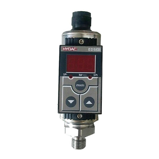
EDS 300 — это компактное электронное реле давления со встроенным цифровым дисплеем. Доступны 4 различных версии выхода: с одной точкой переключения, с двумя точками переключения и те же два варианта, а также с дополнительным аналоговым выходным сигналом 4 … 20 мА. Точки переключения и соответствующие гистерезисы могут быть установлены с клавиатуры. Для оптимальной адаптации к соответствующему применению устройство предлагает множество дополнительных параметров настройки, например: время задержки переключения, функции открывания / закрывания розеток. Основное применение EDS 300 — сообщения о давлении и предельных значениях в области гидравлики и пневматики или там, где высокая частота переключения или постоянная точность переключения больше, чем могут обеспечить механические реле давления. Устройство идеально подходит для настройки функций зарядки аккумуляторов или блоков управления насосами и компрессорами, а также для контроля давления или предельных значений на судовых трансмиссиях, дизельных двигателях, насосах и общих гидравлических и пневматических установках. Встроенный датчик давления с тонкопленочным DMS на мембране из нержавеющей стали
Технические возможности:
- Компактная, прочная конструкция
- Точность ± 1% полной шкалы
- 3-х символьный цифровой дисплей
- Простое управление за счет программирования ключей
- Точки переключения и гистерезис сброса можно регулировать независимо друг от друга
- Оконная функция
- Множество полезных дополнительных функций
Датчики Hydac — это знак качества в создании гидросистем различных назначений. Датчики скорости, давления, расстояния Хюдак изготавливаются на заводе в Германии. Купить датчики Hydac в России рекомендуем в ООО ПКЦ «Кинематика» официальном сервисном центре по ремонту и поставке гидравлики. Производственно-коммерческий центр «Кинематика» осуществляет консультации, подбор и обучение по всей продукции производителя.

Electronic Pressure Switch
EDS 300
User manual
Stand 10.11.2000
-
Contents
-
Table of Contents
-
Bookmarks
Quick Links
Bedienungsanleitung
(Originalanleitung)
User Manual
(Translation of original
instruction)
Notice d’utilisation
(Traduction de l’original)
Elektronischer
Druckschalter
Electronic
Pressure Switch
Manocontacteur
électronique
EDS 300
Related Manuals for Hydac EDS 300
Summary of Contents for Hydac EDS 300
-
Page 1
Elektronischer Druckschalter Electronic Pressure Switch Manocontacteur électronique EDS 300 Bedienungsanleitung (Originalanleitung) User Manual (Translation of original instruction) Notice d’utilisation (Traduction de l’original) -
Page 2: Table Of Contents
TRANSPORT ………………….5 VERPACKUNG ………………..5 LAGERUNG ………………….5 Montage ………………….5 Funktionen des EDS 300…………….6 Bedienelemente der Folientastatur …………… 7 Digitalanzeige ………………..7 Ausgangsverhalten ………………8 …
-
Page 3
EDS 300 Vorwort Für Sie, den Benutzer unseres Produktes, haben wir in dieser Dokumentation die wichtigsten Hinweise zum Bedienen und Warten zusammengestellt. Sie dient Ihnen dazu, das Produkt kennen zu lernen und seine bestimmungsgemäßen Einsatzmöglichkeiten optimal zu nutzen. Diese Dokumentation muss ständig am Einsatzort verfügbar sein. -
Page 4: Technische Sicherheit
Dadurch wird gewährleistet, dass das Gerät bei der Auslieferung frei von Mängeln ist und die angegebenen Spezifikationen einhält. Die Elektronischen Druckchalter der Serie EDS 300 sind wartungsfrei und arbeiten beim Einsatz innerhalb spezifizierter Bedingungen einwandfrei. Sollte trotzdem ein Grund zur Beanstandung vorliegen, so wenden Sie sich bitte an Ihre HYDAC-Vertretung.
-
Page 5: Transport, Verpackung, Lagerung
ähnliche Messstoffe. Montage Der EDS 300 kann über den Druckanschluss (G¼ A ISO 1179-2) direkt an einem Hydraulikblock montiert werden. Durch die Verwendung des als Zubehör erhältlichen Anschlussadapters ZBM 14 kann sichergestellt werden, dass sich die Anzeige optimal im Sichtbereich des Anwenders befindet.
-
Page 6: Funktionen Des Eds 300
• Anzeigen des aktuellen Druckes, des Maximalwertes oder eines Schaltpunkts. • Schalten der Schaltausgänge entsprechend dem Druck und den eingestellten Schaltparametern. • Analogausgang. • Menü zur Grundeinstellung (Anpassen des EDS 300 an die jeweilige Applikation). • Programmierfreigaben Es stehen 4 verschiedene Ausgangsvarianten zur Verfügung: • 1 Schaltausgang •…
-
Page 7: Bedienelemente Der Folientastatur
EDS 300 Bedienelemente der Folientastatur 3-stellige Digitalanzeige Tasten zur Einstellung der Schaltpunkte, Rückschaltpunkte und Zusatzfunktionen Digitalanzeige Nach Einschalten der Versorgungsspannung zeigt das Gerät kurz «EdS» an und beginnt mit der Anzeige des aktuellen Druckes. In den Grundeinstellungen kann die Anzeige geändert werden. Es ist z.B. möglich permanent den Maximalwert anzuzeigen.
-
Page 8: Ausgangsverhalten
EDS 300 Ausgangsverhalten SCHALTAUSGÄNGE Der EDS 300 verfügt über 1 bzw. 2 Schaltausgänge. In den Grundeinstellungenkann folgendes Schaltverhalten eingestellt werden: 8.1.1 Einstellung auf Schaltpunkt (SP) Zu jedem Schaltausgang kann ein Schaltpunkt und eine Hysterese eingestellt werden. Der jeweilige Ausgang schaltet, wenn der eingestellte Schaltpunkt erreicht wurde und schaltet zurück, wenn der Rückschaltpunkt unterschritten wurde.
-
Page 9: Analogausgang
EDS 300 ANALOGAUSGANG Je nach Ausführung verfügt der EDS 300 über einen Analogausgang mit 4..20 mA Signal. EINSTELLEN DER SCHALTPUNKTE UND HYSTERESEN BZW. SCHALTWERTE FÜR DIE FENSTERFUNKTION • Taste «mode» betätigen. • In der Anzeige erscheint «S.P.1» bzw. «hi.1» • Durch weiteres Betätigen der Taste «mode» den gewünschten Parameter anwählen (je nach Grundeinstellung ist möglich: «S.P.1», «h.Y.1», «S.P.2», «h.Y.2», «hi.1», «Lo.1», «hi.2″…
-
Page 10: Einstellbereiche Für Die Schaltausgänge
• Versorgungsspannung abschalten oder Gerät von der Versorgungsspannung trennen. (Übersicht siehe 8.2) Beenden des Grundeinstellungsmenüs: Den Menüpunkt «END» anwählen, die Einstellung auf «YES» stellen, der EDS 300 kehrt nach 2s in den normalen Anzeigemodus zurück. HINWEISE: • Erfolgt ca. 50 Sekunden lang keine Tastenbetätigung, wird das Menü automatisch beendet, ohne dass eventuelle Änderungen wirksam werden.
-
Page 11: Übersicht Der Grundeinstellungen
EDS 300 ÜBERSICHT DER GRUNDEINSTELLUNGEN Einstellung Anzeige Einstellbereich Voreinstellung SP/ Win Schaltmodus Schaltausgang 1 (Sm 1) Schaltausgang 1 arbeitet in Schaltpunkt / Hysteresefunktion Schaltausgang 1 arbeitet in Fensterfunktion ON/OFF Schaltrichtung Schaltausgang 1 (S 1) «ON » : Schließerfunktion. «OFF «: Öffnerfunktion.
-
Page 12: Programmierfreigaben
EDS 300 10 Programmierfreigaben Das Gerät verfügt über 2 Programmierfreigaben die beide erteilt sein müssen um Einstellungen zu ändern. Die Betriebs-Programmierfreigabe kann während des Betriebes gesetzt bzw. aufgehoben werden. Sie bietet Schutz vor unbeabsichtigten Änderungen. Ein Sperren der Programmierung über die Haupt-Programmierfreigabe bewirkt, dass während des Betriebes keine Änderung der Einstellungen vorgenommen werden kann.
-
Page 13: Fehlermeldungen
EDS 300 11 Fehlermeldungen Wird ein Fehler erkannt, so erscheint eine entsprechende Fehlermeldung, die mit einem beliebigen Tastendruck quittiert werden muss. Mögliche Fehlermeldungen sind: Die Schaltpunkte und Hysteresen wurden so eingestellt, dass der resultierende E.01 Rückschaltpunkt nicht mehr im erlaubten Einstellbereich liegt.
-
Page 14: Technische Daten
EDS 300 12 Technische Daten Eingangskenngrößen Messbereiche 16 | 40 | 100 | 250 | 400 | 600 bar Überlastbereiche 32 | 80 | 200 | 500 | 800 | 1000 bar Berstdruck 200 | 200 | 500 | 1000 | 2000 | 2000 bar…
-
Page 15: Anschlussbelegung
EDS 300 13 Anschlussbelegung 13.1 VERSORGUNGSSPANNUNG, SCHALTAUSGÄNGE, ANALOGAUSGANG Ausführung mit 1 Schaltausgang Stecker EN 175301-803 (DIN 43650), 3-pol. + PE SP 1 Gehäuse Stecker 4-pol. M12x1 n.c. SP 1 Stand: 19.09.2018 Mat. Nr.: 669648 D HYDAC ELECTRONIC GMBH…
-
Page 16
EDS 300 Ausführung mit 2 Schaltausgängen Stecker 4-pol. Binder, Serie 714 M18 SP 1 SP 2 Stecker 4-pol. M12x1 SP 2 SP 1 Stand: 19.09.2018 Mat. Nr.: 669648 D HYDAC ELECTRONIC GMBH… -
Page 17
EDS 300 Ausführung mit 1 Schaltausgang und 1 Analogausgang Stecker 4-pol. Binder, Serie 714 M18 SP 1 Analog Stecker 4-pol. M12x1 Analog SP 1 Ausführung mit 2 Schaltausgängen und 1 Analogausgang Stecker 5-pol. M12x1 Analog SP 1 SP 2 Stand: 19.09.2018 Mat. -
Page 18: Bestellangaben
EDS 300 14 Bestellangaben EDS 3 4 X — X — XXX — 000 Serien-Nr. (werksintern festgelegt) Anschlussart, mechanisch = G1/4 A ISO 1179-2 Anschlussart, elektrisch = Gerätestecker 4-pol.Binder Serie 714 M18 nur für Ausgangsvarianten «2» und «3» (ohne Kupplungsdose) = Gerätestecker 3-pol.
-
Page 19: Zubehör
EDS 300 15 Zubehör 15.1 FÜR DEN ELEKTRISCHEN ANSCHLUSS ZBE 01 Kupplungsdose EN175301-803 (DIN 43650) 3-pol. + PE, abgewinkelt Kabeldurchmesser: 4,5 .. 7 mm Material-Nr.: 905701 ZBE 02 Kupplungsdose Binder Serie 714 M18 4-pol., gerade Kabeldurchmesser: 6,5 .. 8 mm Material-Nr.: 609479…
-
Page 20
EDS 300 ZBE 06 (4-pol.) Kupplungsdose M12x1, abgewinkelt Kabeldurchmesser: 2,5 .. 6,5 mm Material-Nr.: 6006788 ZBE 06-02 (4-pol.) Kupplungsdose M12x1, abgewinkelt mit 2 m Leitung, Material-Nr.: 6006790 ZBE 06-05 (4-pol.), Kupplungsdose M12x1, abgewinkelt mit 5 m Leitung Material-Nr.: 6006789 Pin 1: braun Farbkennung: Pin 2: weiß… -
Page 21
EDS 300 ZBE 08 (5-pol.) Kupplungsdose M12x1, abgewinkelt Kabeldurchmesser: 2,5 .. 6,5 mm Material-Nr.: 6006786 ZBE 08-02 (5-pol.) Kupplungsdose M12x1, abgewinkelt mit 2 m Leitung, Material-Nr.: 6006792 ZBE 08-05 (5-pol.), Kupplungsdose M12x1, abgewinkelt mit 5 m Leitung Material-Nr.: 6006791 Pin 1: braun Farbkennung: Pin 2: weiß… -
Page 22: Für Den Mechanischen Anschluss
ZBM 14 Adapter Innengewinde G1/4 – Außengewinde G1/4 (drehbar) Material-Nr.: 907818 Schelle zur Wandbefestigung des EDS 300 (Werkstoff Polypropylen) ZBM 300 Montage: • Dämpfungsstreifen in die Vertiefung der Bodenplatte einkleben. • Bodenplatte montieren, die Oberseite ist durch Beschriftung «OBEN», «TOP» und 2 Pfeile gekennzeichnet.
-
Page 23: Geräteabmessungen
EDS 300 16 Geräteabmessungen Stand: 19.09.2018 Mat. Nr.: 669648 D HYDAC ELECTRONIC GMBH…
-
Page 24
E-Mail: electronic@hydac.com Tel.: +49 (0)6897 509-01 Fax.: +49 (0)6897 509-1726 HYDAC Service Für Fragen zu Reparaturen stehen Ihnen die HYDAC SYSTEMS & SERVICES zur Verfügung. HYDAC SYSTEMS & SERVICES GMBH Hauptstr. 27 D-66128 Saarbrücken Germany Tel.: +49 (0)6897 509-1936 Fax.:… -
Page 25
Electronic Pressure Switch EDS 300 User Manual (Translation of original instruction) -
Page 26
PACKAGE ………………….5 STORAGE ………………….5 Mounting ………………….5 Functions of the EDS 300 …………….6 Operating keys on the membrane keypad ………… 7 Digital display ………………..7 Output function ………………..8 … -
Page 27
EDS 300 Preface This manual provides you, as user of our product, with key information on the operation and maintenance of the equipment. It allows you to get to know the product and to optimise your use of it for the intended purpose. -
Page 28: Technical Safety
• The EDS 300 must not be put into service if any known defects, either electrical or mechanical, are apparent. • The instructions for use must be strictly adhered to.
-
Page 29: Transportation, Package, Storage
Mounting The EDS 300 can be mounted directly onto a hydraulic block via the pressure connection (G¼ A ISO 1179-2). The connection adaptor ZBM 14 is available as an accessory and is designed to ensure that the display is always visible to the user.
-
Page 30: Functions Of The Eds 300
• Switching the switching outputs according to the pressure and the pre-set switching parameters. • Analogue output • Menu for basic settings (adapting the EDS 300 to the particular application) • Two different types of programming enable Four different output models are available: •…
-
Page 31: Operating Keys On The Membrane Keypad
EDS 300 Operating keys on the membrane keypad 3-digit digital display Keys for setting switching points, switch-back points and additionals functions Digital display After switching on the supply voltage, the unit briefly displays «EdS» and then displays the actual pressure.
-
Page 32: Output Function
EDS 300 Output function SWITCHING OUTPUTS The EDS 300 has 1 or 2 switching outputs. The following settings can be made under the basic setting: 8.1.1 Switching point setting (SP) One switching point and one hysteresis can be set for each switching output. The relevant output switches when the pre-set switching point is reached and switches back when the pressure falls below the switch-back point.
-
Page 33: Analogue Output
EDS 300 ANALOGUE OUTPUT Depending on the model, the EDS 300 has one analogue output with a 4 .. 20 mA signal. SETTING THE SWITCHING POINTS, HYSTERESES AND/OR SWITCHING VALUES FOR THE WINDOW FUNCTION • Press «mode» key • «S.P.1» or «hi.1» is displayed •…
-
Page 34: Setting Ranges For Switching Outputs
*All ranges given in the table are adjustable by the increments shown. Basic settings In order to adapt the unit to a particular application, the function of the EDS 300 can be altered via several basic settings. These are combined in one menu.
-
Page 35: Summary Of The Basic Settings
EDS 300 9.2 SUMMARY OF THE BASIC SETTINGS Setting Display Setting range Presetting SP/ Win Switching mode switching output 1 (Sm 1) Switching output 1 is operating in switching point / hysteresis function Switching output 1 is operating in window function…
-
Page 36: Programming Enables
EDS 300 10 Programming enables The unit has 2 types of programming enable which must both be set to «ON » to change the settings. The operating programming enable can be set or cancelled during operation. It provides protection against inadvertent changes to the unit’s settings.
-
Page 37: Error Messages
Check all the settings (programming enables, switching points, switch-back points Action: and basic settings) and correct these if necessary. If the errors occur frequently, please contact Hydac Service. An error has been detected in the stored calibration data. Possible causes are strong E.12 electromagnetic interference or a component fault.
-
Page 38: Technical Specifications
EDS 300 12 Technical specifications Input data Measuring ranges 16 | 40 | 100 | 250 | 400 | 600 bar Overload pressures 32 | 80 | 200 | 500 | 800 | 1000 bar 200 | 200 | 500 | 1000 | 2000 | 2000 bar…
-
Page 39: Circuit Diagram
EDS 300 13 Circuit diagram 13.1 SUPPLY VOLTAGE, SWITCHING OUTPUTS, ANALOGUE OUTPUT Model with 1 switching output Male EN 175301-803 (DIN 43650), 3 pole + PE SP 1 Housing Male M12x1, 4 pole n.c. SP 1 Status: 19.09.2018 Part No.: 669648 E…
-
Page 40
EDS 300 Model with 2 switching outputs Male 4 pole Binder series 714 M18 SP 1 SP 2 Male M12x1, 4 pole SP 2 SP 1 Status: 19.09.2018 Part No.: 669648 E HYDAC ELECTRONIC GMBH… -
Page 41
EDS 300 Model with 1 switching output and 1 analogue output Male 4 pole Binder series 714 M18 SP 1 Analogue Male M12x1, 4 pole Analogue SP 1 Model with 2 switching outputs and 1 analogue output Male M12x1, 5 pole… -
Page 42: Model Code
EDS 300 14 Model code EDS 3 4 X — X — XXX — 000 Series-no. (determined by manufacturer) Mechanical connection = G1/4 A ISO 1179-2 Anschlussart, elektrisch = Male 4 pole Binder series 714 M18 only possible on output models «2» and «3»…
-
Page 43: Accessories
EDS 300 15 Accessories 15.1 FOR ELECTRICAL CONNECTION ZBE 01 Female connector EN175301-803 (DIN 43650) 3 pole + PE, right-angle Cable diameter: 4.5 .. 7 mm Part No.: 905701 ZBE 02 Female connector Binder Serie 714 M18 4 pole, straight Cable diameter: 6.5 ..
-
Page 44
EDS 300 ZBE 06 (4 pole) Female connector M12x1, right-angle Cable diameter: 2.5 .. 6.5 mm Part No.: 6006788 ZBE 06-02 (4 pole) Female connector M12x1, right-angle with 2 m cable Part No.: 6006790 ZBE 06-05 (4pole), Female connector M12x1, right-angle with 5 m cable Part No.:… -
Page 45
EDS 300 ZBE 08 (5 pole) Female connector M12x1, right-angle Cable diameter: 2.5 .. 6.5 mm Part No.: 6006786 ZBE 08-02 (5 pole) Female connector M12x1, right-angle with 2 m cable Part No.: 6006792 ZBE 08-05 (5 pole), Female connector M12x1, right-angle with 5 m cable Part No.:… -
Page 46: For Mechanical Connection
G1/4 (rotating) Part No.: 907818 elastomer seal ring DIN 3869 clamp for wall-mounting the EDS 300 (material: polypropylene) ZBM 300 Mounting: • Glue damping strips into the recesses of the base plate. • Mount base plate, the top is indicated by «OBEN «, «TOP «…
-
Page 47: Dimensions
EDS 300 16 Dimensions Male electrical connection Binder series 714-4p Male electrical connection 4p / 5p seal elastomer seal ring DIN 3869 Status: 19.09.2018 Part No.: 669648 E HYDAC ELECTRONIC GMBH…
-
Page 48
Tel.: +49 (0)6897 509-01 Fax.: +49 (0)6897 509-1726 HYDAC Service For enquiries about repairs or alterations, please contact HYDAC SYSTEMS & SERVICES. HYDAC SYSTEMS & SERVICES GMBH Hauptstr. 27 D-66128 Saarbrücken Germany Tel.: +49 (0)6897 509-1936 Fax.: +49 (0)6897 509-1933 Note The information in this manual relates to the operating conditions and applications described. -
Page 49
Manocontacteur électronique EDS 300 Notice d’utilisation (Traduction de l’original) -
Page 50
EMBALLAGE ………………….5 STOCKAGE ………………….5 Montage ………………….5 Fonctionnement de l’EDS 300 …………… 6 Eléments fonctionnels de la face avant …………7 Affichage digital ………………… 7 Caractéristiques de sorties …………….8 … -
Page 51
EDS 300 Avant-propos Nous avons rassemblé dans cette documentation, à l’attention de tout acquéreur d’un produit fabriqué par nos soins, les recommandations essentielles pour l’utilisation et la maintenance de ce produit. Cette notice a pour objectif de simplifier la prise en main du produit et l’exploitation optimale de ses possibilités d’utilisation, conformément à… -
Page 52: Introduction
à une mauvaise utilisation de l’appareil, veuillez prendre connaissance des points suivants : • L’EDS 300 ne doit être mis en service que s’il est dans un état technique et visuel irréprochable.
-
Page 53: Transport, Emballage, Stockage
Montage L’EDS 300 peut être monté directement sur un bloc hydraulique par l’intermédiaire du raccordement process ( G 1/4A ISO 1179-2) par l’utilisation du raccord d’adaptation ZBM 14, il est garanti que l’indicateur sera lisible par l’utilisateur.
-
Page 54: Fonctionnement De L’eds 300
• Commutation des sorties sur seuil correspondant à la pression actuelle et aux paramètres de commutation réglés • Sortie analogique • Menu pour réglages de base (adaptation de l’EDS 300 à l’application) • Protection de programmation 4 variantes existent: • 1 sortie de commutation •…
-
Page 55: Eléments Fonctionnels De La Face Avant
EDS 300 Eléments fonctionnels de la face avant Indicateur digital 3 positions Touches pour réglages des seuils d’enclenchement, déclenchement et fonctions annexes Affichage digital Après mise sous tension , il est affiché brièvement «EdS» puis la pression actuelle est donnée L’affichage peut être modifié…
-
Page 56: Caractéristiques De Sorties
EDS 300 Caractéristiques de sorties SORTIE SUR SEUIL L’ED S 300 dispose selon les versions d’1 ou 2 seuils. Il va être possible dans le menu «Réglages de base» de choisir comment utiliser le contact en sortie. Deux choix sont offerts.
-
Page 57: Sortie Analogique
EDS 300 SORTIE ANALOGIQUE Selon l’exécution, une sortie analogique 4 .. 20 mA existe. RÉGLAGE DES POINTS DE COMMUTATION ET D’HYSTÉRÉSIS OU VALEURS LIMITES POUR FONCTION FENETRE • Appuyer sur «mode» • Il apparaît «S.P.1» ou «h.i1» • En réappuyant sur la touche «mode», il est possible de sélectionner le paramètre voulu selon le choix effectué…
-
Page 58: Plages De Réglage Pour Les Sorties De Commutation
(pendant environ 3s). suivant Sortir du menu réglage de base: Sélectionner la fonction «END», valider «YES» : après 2 secondes, l’EDS 300 repasse en mode normal. REMARQUE • Si au bout de 50 secondes, il n’a pas été actionné de touche, l’affichage retourne à…
-
Page 59: Apperçu Des Réglages De Base
EDS 300 APPERÇU DES RÉGLAGES DE BASE Réglage Affichage Etendue de Préréglage réglage SP/ Win Mode de commutation du seuil 1 (Sm 1) Le contact 1 travaille avec valeur d’enclenchement / hystérésis Le contact 1 travaille en fonction fenêtre ON/OFF Sens de commutation du seuil 1 (S 1) «ON «:…
-
Page 60: Autorisation De Programmation
EDS 300 10 Autorisation de programmation L’EDS 300 contient 2 autorisations de programmation qui doivent toutes 2 être actives pour permettre de modifier les réglages. L’autorisation de programmation de service peut être activée ou verrouillée en cours de fonctionnement pour éviter toutes modifications de valeurs de seuil. Grâce au verrouillage de l’autorisation de programmation haute, aucun réglage ne peut être modifié…
-
Page 61: Codes D’erreur
Lors de la sauvegarde des réglages, une erreur a été détectée. La cause provient E.12 sûrement de perturbations électromagnétiques ou d’un défaut matériel. Déconnecter l’EDS 300 de la source d’alimentation puis le rebrancher. Si Remède: l’information d’erreur apparaissait encore après cette manipulation, il est nécessaire de renvoyer le manocontacteur à…
-
Page 62: Caractéristiques Techniques
EDS 300 12 Caractéristiques techniques Valeurs d’entrée Plages de mesure 16 | 40 | 100 | 250 | 400 | 600 bar Plages de surcharge 32 | 80 | 200 | 500 | 800 | 1000 bar 200 | 200 | 500 | 1000 | 2000 | 2000 bar Pression d‘éclatement…
-
Page 63: Configuration Des Sorties
EDS 300 13 Configuration des sorties 13.1 TENSION D’ALIMENTATION, SORTIES DE COMMUTATION, SORTIE ANALOGIQUE Exécution avec 1 sortie de commutation Embase EN 175301-803 (DIN 43650), 3 pôles + PE SP 1 Boîte Embase 4 pôles M12x1 n.c. SP 1 Edition: 19.09.2018…
-
Page 64
EDS 300 Exécution avec 2 sorties de commutation Embase 4 pôles série Binder 714 M18 SP 1 SP 2 Embase 4 pôles M12x1 SP 2 SP 1 Edition: 19.09.2018 Code article : 669648 F HYDAC ELECTRONIC GMBH… -
Page 65
EDS 300 Exécution avec 1 sortie de commutation et 1 sortie analogique Embase 4 pôles série Binder 714 M18 SP 1 Analogique Embase 4 pôles M12x1 Analogique SP 1 Exécution avec 2 sorties de commutation et 1 sortie analogique Embase 5 pôles M12x1… -
Page 66: Code De Commande
EDS 300 14 Code de commande EDS 3 4 X — X — XXX — 000 N° de série interne (déterminé en usine) Raccordement mécanique = G1/4 A ISO 1179-2 Raccordement électrique = Embase 4 pôles série Binder 714 M18 pour variantes de sortie «2»…
-
Page 67: Accessoires
EDS 300 15 Accessoires 15.1 POUR LE RACCORDEMENT ÉLECTRIQUE ZBE 01 Connecteur EN175301-803 (DIN 43650) 3 pôles + PE, coudé Diamètre de câble: 4,5 .. 7 mm Code article: 905701 ZBE 02 Connecteur Binder, série 714 M18 4 pôles, droit Diamètre de câble:…
-
Page 68
EDS 300 ZBE 06 (4 pôles) Connecteur M12x1, coudé Diamètre de câble: 2,5 .. 6,5 mm Code article: 6006788 ZBE 06-02 (4 pôles) Connecteur M12x1, coudé avec 2 m de câble, Code article: 6006790 ZBE 06-05 (4 pôles) Connecteur M12x1, coudé… -
Page 69
EDS 300 ZBE 08 (5 pôles) Connecteur M12x1, coudé Diamètre de câble: 2,5 .. 6,5 mm Code article: 6006786 ZBE 08-02 (5 pôles) Connecteur M12x1, coudé avec 2 m de câble, Code article: 6006792 ZBE 08-05 (5 pôles), Connecteur M12x1, coudé… -
Page 70: Pour Le Raccordement Mécanique
ZBM 14 Adapteur femelle G1/4 – mâle G1/4 (rotatif) Code article: 907818 Collier pour montage mural de l’EDS 300 (matière: polypropylène) ZBM 300 Montage: • Coller la partie élastomère sur l’embase. • Monter l’embase en veillant à respecter les flèches et inscriptions «OBEN «, «TOP «.
-
Page 71: Dimensions
EDS 300 16 Dimensions Embase série Binder 714- 4p Embase série 4p / 5p Joint Joint profilé élastomère DIN 3869 Edition: 19.09.2018 Code article : 669648 F HYDAC ELECTRONIC GMBH…
-
Page 72
E-Mail: electronic@hydac.com Tel.: +49 (0)6897 509-01 Fax.: +49 (0)6897 509-1726 HYDAC Service HYDAC SYSTEMS & SERVICES se tient à votre disposition pour toute question concernant les réparations. HYDAC SYSTEMS & SERVICES GMBH Hauptstr.27 D-66128 Saarbrücken Allemagne Tél. : +49 (0) 6897 / 509 – 1936 Fax : +49 (0) 6897 / 509 –…
Electronic Pressure Switch
EDS 300
User manual
Stand 10.11.2000

1. Functions of the EDS 300
Depending on the model, the unit offers the following functions:
•Display of the actual pressure, maximum value or a switching point.
•Switching the switching outputs according to the pressure and the pre-set switching parameters.
•Analogue output
•Menu for basic settings (adapting the EDS 300 to the particular application)
•Two different types of programming enable
Three different output models are available:
•EDS 300 with 1 switching output (1.2 A load capacity, no analogue output)
•EDS 300 with 2 switching outputs (1.2 A load capacity, no analogue output)
•EDS 300 with 1 switching output (1.2 A load capacity) and 1 analogue output (4…20 mA)
2. Mounting
The EDS 300 can be mounted directly onto a hydraulic block via the pressure connection (7/16 SAE 4 female).
When used in critical applications (e.g. strong vibrations or knocks) the pressure connection must be mechanically decoupled via a Minimess hose. Mounting clamps are available as an accessory (see point 12.2 «Accessories — for mechanical connection»).
The electrical connection should be carried out by a qualified electrician according to the relevant regulations of the country concerned (VDE 0100 in Germany). The pressure switch housing must be earthed properly at the same time. When fitted into a hydraulic block it is sufficient if the block is earthed via the hydraulic system. In the case of Minimess hosemounting, the housing must be earthed separately.
Additional assembly notes which, from experience, reduce the effect of electromagnetic interference:
•Make line connections as short as possible.
•Use screened lines (e.g. LIYCY 4 x 0.5 mm2)
•The cable screening must be fitted by qualified personnel subject to the ambient conditions and with the aim of suppressing interference.
•Direct proximity to connecting lines of user units or electrical or electronic units causing interference must be avoided as far as possible.
3. Operating keys on the membrane keypad
4-digit
digital display
keys for setting switching points, switch-back points and additional functions
4. Digital display

After switching on the supply voltage, the unit briefly displays “EdS” followed by the current pressure.
 2 s
2 s
In the basic settings the display can be altered. For example, the maximum value can be permanently displayed. This is the largest measured value which has been recorded since the unit was switched on or was last re-set. A switching point can likewise be permanently displayed or the display can be set to be dark. Depending on the setting, «TOP«, «S.P. 1«, «S.P. 2» or «OFF» appears briefly on the display following the switch-on message.
The actual pressure can be displayed briefly by pressing the  or the
  key. This causes the maximum value to be re-set.
Notes:
•If the actual pressure exceeds the nominal pressure of the unit, it can no longer be displayed and the display begins to flash.
•If the actual pressure is below 1 % of the nominal range, then 0 is displayed.

5. Output function
5.1 Switching outputs
The EDS 300 has 1 or 2 switching outputs. The following settings can be made under the basic setting:
5.1.1 Switching point setting (SP)
One switching point and one hysteresis can be set for each switching output. The respective output switches when the pre-set switching point is reached and switches back when the pressure falls below the switch-back point. The switch-back point is determined by the preset hysteresis (switch-back point = switching point minus hysteresis).
Abbreviations: «S.P.1», «S.P.2» = switching point 1 or 2
«h.Y.1», «h.Y.2» = hysteresis 1 or 2
5.1.2 Window function setting (WIN)
The window function enables a range to be monitored. For each switching output, in each case an upper and a lower switching value can be input which determine the range.
The respective output switches when the pressure enters this range. Upon leaving the range, i.e. when the switch-back value has been reached, the output switches back. The lower switch-back value is just below the lower switching value (lower switching value minus three times the increment, see point 5.4). The upper switch-back value is just above the upper switching value (upper switching value plus three times the increment, see point 5.4). The area between switching and switch-back value forms a safety zone which prevents unwanted switching operations from occurring (e.g. triggered by pulsations from a pump).
Example for switching output 1 (normally open function):
P 
|
hi.1 plus 3xincrement |
Off |
Switch-back valuet |
|
|
Safety zone |
|||
|
hi.1 |
Switching value |
||
|
On |
|||
|
Lo.1 |
On |
Switching value |
|
|
Safety zone |
|||
|
Lo.1 minus 3xincrement |
Switch-back value |
||
|
Off |
t
ON
Off
Abbreviations: «hi.1«, «hi.2» = High level 1 or 2 «Lo.1«, «Lo.2» = Low level 1 or 2
=upper switching value 1 or 2
=lower switching value 1 or 2
Note: The window function only operates correctly (switching on and off), when all switching values (including the safety zone) are greater than 0 bar and lower than the nominal pressure range.
5.2 Analogue output
On specified models, the EDS 300 provides one analogue output with a 4…20 mA signal.
5.3. Setting the Switching Points and Hystereses

•Press «mode» key
•«S.P.1» or «hi.1» is displayed
•Keep pressing the «mode» key until the required parameter is displayed (depending on the basic setting: «S.P.1», «h.Y.1», «S.P.2», «h.Y.2», «hi.1», «Lo.1», «hi.2» or «Lo.2»).
•After 2 seconds the actual setting flashes.
•Use the  or the
  keys to alter the setting.
•Use the «mode» key to call up other parameters, if required, and alter the setting using the  and the
  keys.
keys.
•If no keys are pressed for 3 seconds, the display changes back and the settings are saved.
|
mode |
||||
|
mode |
||||
|
pressure |
||||
|
display |
||||
|
3 s |
||||
|
press “mode” key |
display |
2 s |
||
|
set switching point |
||||
|
until the required |
=smaller value |
|||
|
parameter is |
=larger value |
|||
|
reached. |
Notes:
•If «LOC» appears in the display when trying to alter the settings, programming is disabled. Corrective action: set programming enable to «ON»
(see point 7 «Programming enable»)
•If the  or the
  key is held down during alteration, the value automatically advances.
•If a setting has been altered, «PRG» appears briefly in the display when the display is switched over. The new setting is then saved in the unit.
5.4 Setting ranges of the switching points and/or hystereses
|
Measuring range |
Switching point |
Hysteresis and/or |
Increment * |
||||
|
in psi |
and/or upper |
lower critical value |
in psi |
||||
|
critical value |
in bar |
||||||
|
in bar |
|||||||
|
-14 .. |
75 |
-12.5 .. |
75.0 |
-0.5 .. |
74.0 |
0.5 |
|
|
0 |
.. |
150 |
3 .. |
150 |
1 .. |
148 |
1 |
|
0 |
.. 1000 |
15 .. |
1000 |
5 .. |
990 |
5 |
|
|
0 |
.. 3000 |
45 .. |
3000 |
15 .. |
2970 |
20 |
|
|
0 |
.. 6000 |
90 .. |
6000 |
30 .. |
5940 |
30 |
|
|
0 |
.. 9000 |
150 .. |
9000 |
50 .. |
8900 |
50 |
* All ranges given in the table are adjustable by the increments shown.
6. Basic settings
 Loading…
-
Mega System Tech
ez-11b
SingleOutletRemotePowerSwitchUserGuideSetupwiththefreemobileapp:1. ConnecttheSingleOutletRemotePowerSwitchtotheincludedpowercordandplugintoapowersource.2. ConnectoneendoftheincludedEthernetCa …
ez-11b Switch, 8
-
HP
StorageWorks XP48 — Disk Array
HP StorageWorks Disk Array XPoperating system configurationguideXP48XP128XP512XP1024XP12000fourth edition (November 2004) part number: A5951-96132This guide describes the requirements and procedures for connecting and configuring the XP family of disk arrays to work with an AlphaServer running the OpenVMS operating sy …
StorageWorks XP48 — Disk Array Disk array system, 50
-
3onedata
IES6300 Series
IES6300 SeriesManaged Industrial Ethernet SwitchQuick Installation Guide3onedata Co., Ltd.Address: 3/B, Zone 1, Baiwangxin High TechnologyIndustrial Park, Xili, Nanshan District, ShenzhenWebsite: www.3onedata.comTel: +86 0755-26702688Fax: +86 0755-26703485【Package Checklist】Please check whether the package and acce …
IES6300 Series Switch, 5
-
3Com
SuperStack 3C16072
Superseded Products The following superseded products may be powered from the Advanced RPS. Again their usage is subject to the total power limitation of 480 watts. Superseded Products requiring a 60 watt Power Module LinkBuilder Hubs 3C215A Hub 100 Management Unit 3C250-TX FMS 100 TX 3C16665 FMS II Fiber (also wit …
SuperStack 3C16072 Power Supply, 2
-
Raritan
Dominion KX IV-101
KX4-101 QSG 1 QSG-KX4101-1A-v4.0.0-E 255-62-0022-00-RoHS Dominion KX IV–101 (DKX4-101) Thank you for purchasing the Dominion KX IV–101, part number DKX4-101. Package Contents • 1 Dominion KX IV–101 • 1 locking power cord • 1 HDMI cable • 1 USB-B to USB-A cable • 1 mounting bracket kit …
Dominion KX IV-101 Switch, 3
-
Cisco
IE-3000-8TC
Americas HeadquartersCisco Systems, Inc.170 West Tasman DriveSan Jose, CA 95134-1706 USAhttp://www.cisco.comTel: 408 526-4000800 553-NETS (6387)Fax: 408 527-0883Cisco IE 3000 Switch Hardware Installation Guide June 2008Text Part Number: OL-13017-01 …
IE-3000-8TC Switch, 170