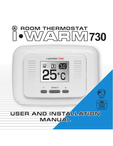
i warm 730 инструкция
Внимание! перед началом использования внимательно ознакомьтесь с данной инструкцией.
Важно! На неисправности прибора, возникшие вследствие механического повреждения, неправильного монтажа или эксплуатации в целях и условиях, не предусмотренных инструкцией по установке и эксплуатации прибора, гарантия производителя не распространяется.
Инструкция по установке и схема подключения не заменяет профессиональной подготовки монтажника прибора.
Мы рекомендуем при монтаже терморегулятора i warm 730 и системы обогрева воспользоваться услугами квалифицированных специалистов. Электрические соединения и подключение прибора к сети должен выполнять квалифицированный электрик.
Обесточьте проводку перед подключением терморегулятора или его отключением для тестирования.
Введение
Поздравляем Вас с приобретением новой интеллектуальной системы управления обогревом i warm 730. Терморегулятор i warm 730 является продолжением серии терморегуляторов, отличающихся высокой надежностью, удобной настройкой и индикацией, современным дизайном.
i warm 730 сделает обогрев в Вашем доме более экономичным, максимально комфортным, простым и приятным в использовании.
Функциональное описание
Терморегулятор i warm 730 предназначен для управления электрическими системами обогрева помещений Теплый пол (нагревательными матами или кабельными секциями) в двух смежных помещениях. Прибор автоматически поддерживает заданную Вами комфортную температуру по показаниям датчиков температуры пола (входящих в комплект поставки). На дисплее отображается температура пола (текущая и заданная Вами для поддержания ). i warm 730 проводит самодиагностику, выводя на дисплей сообщения при неисправности датчика температуры пола (подробнее см. стр. 11). В этом случае прибор может работать в так называемом «сервисном» режиме управления обогревом (подробнее см. стр. 12)
Информация на заметку: терморегулятор для теплого пола i-warm 720, терморегулятор для теплого пола i-warm 710
-
Contents
-
Table of Contents
-
Bookmarks
Quick Links
Related Manuals for I WARM 730
Summary of Contents for I WARM 730
-
Page 2: Table Of Contents
Table of contents: Introduction ……..4 Functional description .
-
Page 3
ATTENTION! Read the present manual carefully before using the device. NOTE! Find connection diagram and device installation directions in the Installation manual. We recommend you to use the services of professional people for thermostat and heating system installation. Ask a qualified electrician to perform all connections and power net working of the device. -
Page 4: Introduction
Introduction Congratulations! You have purchased a new I WARM heat management system. I WARM 730 thermostat series have inherent fea tures that are highly reliable, easy adjustment, simple display and modern design. I WARM 730 will make the heating in your home more…
-
Page 5: Functional Description
Functional description I WARM 730 thermostat is designed to manage «Warmfloor» (heating mats or cable sections) electrical heat ing systems for two separate areas. The device automatically maintains the comfortable temperature set by you, using the readings of floor temperature sensors (included); these sen sors are located in two various heating zones (in two areas).
-
Page 6: Controls And Display
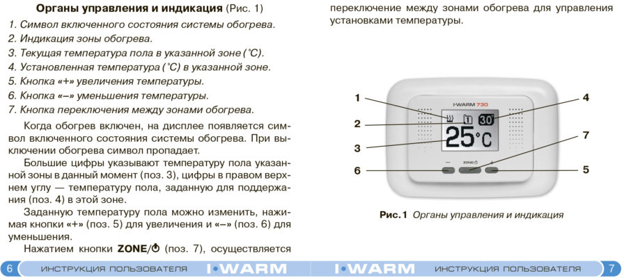
Controls and display (fig.1) 1. Symbol for heating system switched on mode. 2. Chosen heating zone No. display. 3. Current floor temperature in the chosen zone (°С). 4. Set temperature (°С) in the chosen zone. 5. «+» key for temperature increase. 6.
-
Page 7
Pressing the ZONE/A A key (position 7) once will shift the heating zone in order to manage temperature settings in each zone. Fig.1 Controls and display… -
Page 8: Managing And Operating
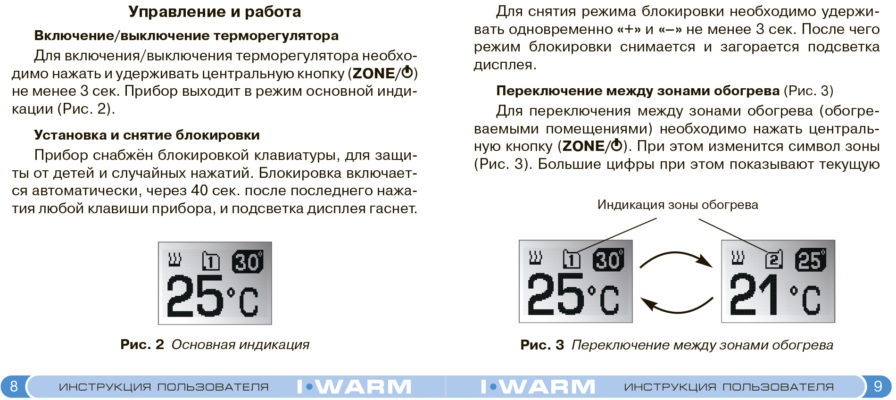
Managing and operating Switching thermostat on/off (Automatic Mode) To switch the thermostat on/off you should press and hold the central key (ZONE/A A ) for not less than 3 sec. The device goes into the main display mode (fig. 2). Blocking and Deblocking The device is equipped with key blocking to protect it from children and accidental pressing.
-
Page 9: Shifting The Heating Zones
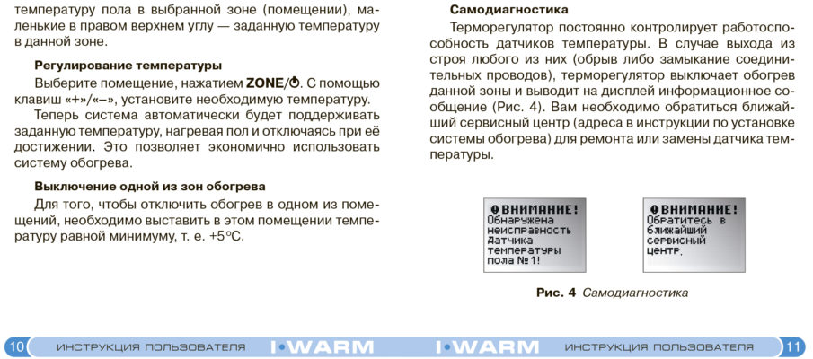
In order to deblock the device, you should press and hold simultaneously «+» and «–» keys for not less than 3 sec. After it the blocking mode is switched off, and the display lights up. Alternating the heating zones (Fig. 3) In order to alternate between the heating zones (heated areas) you should press the central key (ZONE/A A ).
-
Page 10: Temperature Adjustment
(area), small figures at top right show the temperature set in this zone. Temperature adjustment Choose area by pressing ZONE/A A . Enter the required temperature using «+»/»–» keys. Now the system will maintain the set temperature auto matically by heating up the floor and switching off when the set temperature is reached.
-
Page 11: Self Diagnostics
Self diagnostics The thermostat controls constantly the working capacity of the temperature sensors. In case any of them is out of order (break or short circuit of leads takes place), the ther mostat switches off heating of this zone and displays warn ing messages (fig.
-
Page 12: Heating Management Mode Without Floor Temperature Sensor
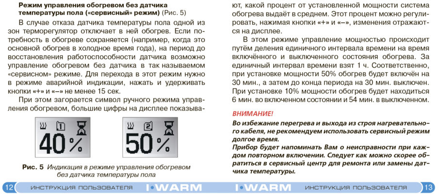
Heating management mode without floor temperature sensor («service mode») (Fig. 5) In case of floor temperature sensor failure in one of the zones the thermostat switches the heating off. If it is still required to heat the areas (e.g. it is the main source of heat ing in winter period), it is possible to manage the heating without a sensor until the working capacity of the sensor is restored (so called «service mode»).
-
Page 13
This percentage may be adjusted by pressing «+» and «–» keys; the changes are shown on the display. In this mode the power is managed the following way: a unit time is divided by the time the heating is in on and off modes. -
Page 14: Using Various Heating Management Modes Simultaneously
Using various heating management modes simultaneously I WARM 730 allows to use both automatic and service modes simultaneously (one mode for each controlled area). In this case the «service mode» zone will be displayed on the screen (fig. 5) even though two separate modes are running simultaneously.
-
Page 15: Installation And Connection
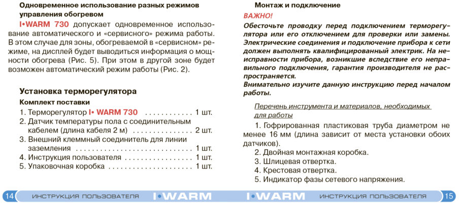
Installation and connection IMPORTANT! Switch off the wiring before installing a thermostat whether checking or replacing. A qualified electrician must perform electrical connections and device connection to the heater. The manufacturer’s guarantee doesn’t cover malfunction due to incorrect connections/installation of the unit. Please study the present manual carefully before commence ment of all electrical connections.
-
Page 16
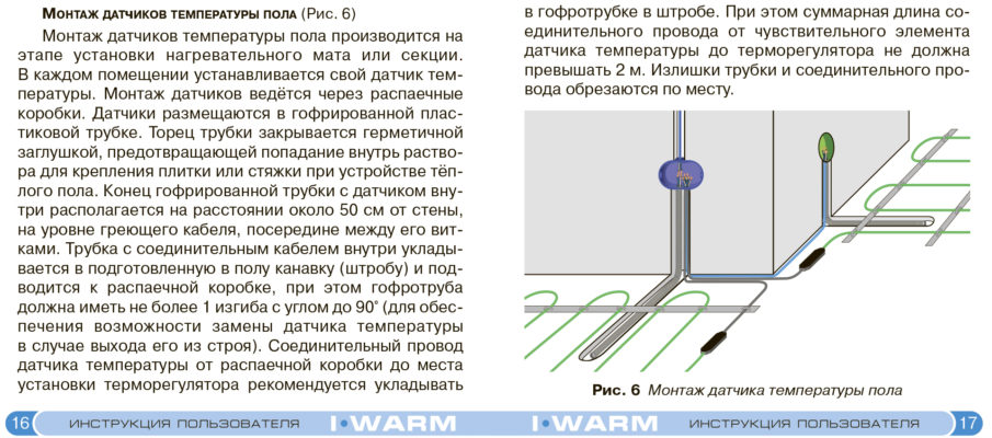
(Fig. 6) NSTALLATION OF FLOOR MOUNTING TEMPERATURE SENSORS Installation of floor temperature sensors is performed when heating mat or section is being installed. In each area its own temperature sensor is installed. The sensors installa tion is performed via a junction box. The sensors are placed in corrugated plastic tube. -
Page 17
Fig. 6 Installation of floor temperature sensor… -
Page 18
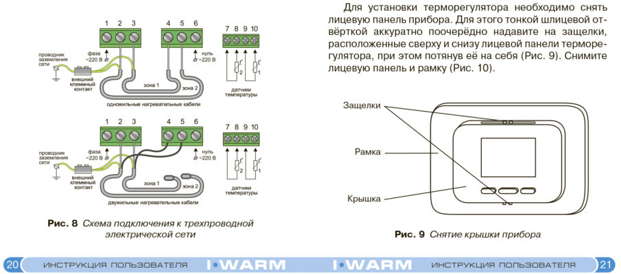
INSTALLATION OF THERMOSTAT Preparing electrical connectors Locate position of your junction box then terminate cold tails for heaters and cable connections for floor sensors. Perform all works regarding thermostat connection only when the power supply is switched off. All the cables are to be connected to the device terminal contacts with screw fastening (See figure 7 for wiring connections). -
Page 19
Network earthig Phase Zero conductor 240 VAC 240 VAC External terminal Zone 1 Sensors of temperature Zone 2 contact Single-core heating cables/mats Network Phase Zero earthig conductor 240 VAC 240 VAC External terminal Zone 1 Sensors of temperature contact Double-core heating cables/mats Fig. -
Page 20
To install a thermostat you should take off the front cover of the device. To do this, slightly push the locks one by one (which are situated at the top and at the bottom of the front cover) using thin screwdriver. At this time pull the front cover out (Fig. -
Page 21
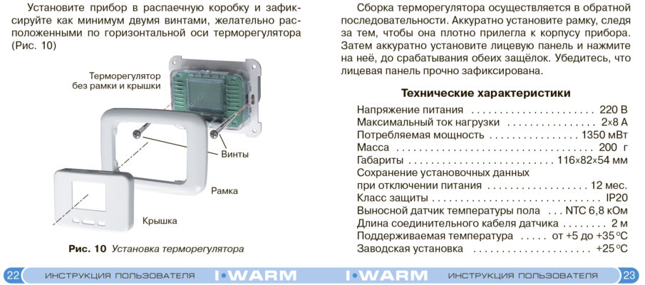
Place the device into the back box and fix it by means of at least two screws, which we recommend you to place along the thermostat horizontal level (Fig. 9) Thermostat without frame and cover Screws Frame Cover Fig. 9 Installation of thermostat… -
Page 22: Technical Specifications
CAUTION — Do not at any time place pressure on the LED Screen during installation! Assemble the thermostat acting in reverse order. Place the frame carefully; be sure, that it fits tightly to the device’s case. Then place the front cover carefully and push it till both locks fix it.
-
Page 23
NOTES…
Specifications:1265/1265068-730.pdf file (13 May 2023) |
Accompanying Data:
I WARM 730 Thermostat PDF User And Installation Manual (Updated: Saturday 13th of May 2023 07:29:02 PM)
Rating: 4.5 (rated by 60 users)
Compatible devices: 410-TC, MCS 300, 3155100, Microtemp MTC4, By-me Eikon 20513, SunStat Pro II 500775, 710, 760.
Recommended Documentation:
Text Version of User And Installation Manual
(Ocr-Read Summary of Contents of some pages of the I WARM 730 Document (Main Content), UPD: 13 May 2023)
-
22, CAUTION — Do not at any time place pressure on the LED Screen during installation! Assemble the thermostat acting in reverse order. Place the frame carefully; be sure, that it fits tightly to the device’s case. Then place the front cover carefully and push it till both locks fix it. Be sure that the f…
-
2, 2 Table of contents: Introduction . . . . . . . . . . . . . . . . . . . . . . . . . . . . . . . . . . . . 4 Functional description . . . . . . . . . . . . . . . . . . . . . . . . . . . . 5 Controls and display . . . . . . . . . . . . . . . . . . . . . . . . . . . . . 6 Managing and operating . . . …
-
14, I WARM 730 14 Using various heating management modes simultaneously I WARM 730 allows to use both automatic and service modes simultaneously (one mode for each controlled area). In this case the «service mode» zone will be displayed on the screen (fig. 5) even though two separate modes are running …
-
12, I WARM 730 Heating management mode without floor temperature sensor («service mode») (Fig. 5) In case of floor temperature sensor failure in one of the zones the thermostat switches the heating off. If it is still required to heat the areas (e.g. it is the main source of heat ing in winter period), it is possible to…
-
I WARM 730 User Manual
-
I WARM 730 User Guide
-
I WARM 730 PDF Manual
-
I WARM 730 Owner’s Manuals
Recommended: F20, Audi S6, PRYSMA B
-
Salus T105RF
Battery InstallationYour thermostat uses two (2) “AA” size batteries to operate. To power-up the unit, insert two “AA” batteries into the battery compartment of the front housing. When power is applied for the first time, the display must show time and the day as well as the room temperature (for example 28. …
T105RF 2
-
DOMISI WTS2000
Power button( )Pairing button( )CDCLOCKSETHEATTARGET CURRENTCOOLSET OKThis new innovation Programmable Wireless Thermostat is intended for automatic control elctrical heating in winter/cold areaor control electrical cooling devices in summer/hot area.It consisted of 2 componets: a Remote Co …
WTS2000 3
-
DELTA DORE TYBOX 817 W RF
TYBOX 827 RFTYBOX 817- 827 W RF1 and 2-channel wireless programmers with built-in thermostatInstallation instructionsDelta Dore hereby declares that the equipment complies with the essential requirements and other relevant provisions of the R&TTE Directive 1999/5/EC.The EC declaration of conformity for this …
TYBOX 817 W RF 2
-
Steamist DSC-425
3STARTSTOPTIMETEMPSENSOR HEAT216TIME / TEMP4 5Installation and Operating InstructionsC US ® 02/09Pub. No. 120-F- 1 — Control Features 1. Temperature Sensor: Measures temperature inside steamroom. 2. Temperature/Timer Display: Counts down remaining minutes and shows programmed minutes, set temperature …
DSC-425 4
Additional Information:
Operating Impressions, Questions and Answers:
730
Table of contents:
Introduction . . . . . . . . . . . . . . . . . . . . . . . . . . . . . . . . . . . .
Functional description . . . . . . . . . . . . . . . . . . . . . . . . . . . .
Controls and display . . . . . . . . . . . . . . . . . . . . . . . . . . . . .
Managing and operating . . . . . . . . . . . . . . . . . . . . . . . . . .
Switching thermostat on/off . . . . . . . . . . . . . . . . . . . . . . . . . .
Blocking and Deblocking . . . . . . . . . . . . . . . . . . . . . . . . . . . .
Shifting the heating zones . . . . . . . . . . . . . . . . . . . . . . . . . . .
Temperature adjustment . . . . . . . . . . . . . . . . . . . . . . . . . . . .
Switching one of the heating zones off . . . . . . . . . . . . . . . . . . .
Selfdiagnostics . . . . . . . . . . . . . . . . . . . . . . . . . . . . . . . . .
Heating management mode without floor temperature sensor . . . .
Using various heating management modes simultaneously . . . . . .
Thermostat installation . . . . . . . . . . . . . . . . . . . . . . . . . . .
Delivery set . . . . . . . . . . . . . . . . . . . . . . . . . . . . . . . . . . . .
Installation and connection . . . . . . . . . . . . . . . . . . . . . . . . . . .
Technical Specifications . . . . . . . . . . . . . . . . . . . . . . . . . .
2
4
5
6
8
8
8
9
10
10
11
12
14
14
14
15
23
ATTENTION!
Read the present manual carefully before using the device.
NOTE!
Find connection diagram and device installation directions in
the Installation manual.
We recommend you to use the services of professional people
for thermostat and heating system installation. Ask a qualified
electrician to perform all connections and power networking
of the device.
Manufacturer's guarantee does not cover device's malfunc
tions caused by mechanical damage, improper installation, or
exploitation for purposes or under conditions not provided by
User and Installation Manual.
3
Introduction
Congratulations! You have purchased a new I WARM heat
management system.
The I WARM 730 thermostat series have inherent fea
tures that are highly reliable, easy adjustment, simple display
and modern design.
IWARM 730 will make the heating in your home more
efficient, most comfortable, easy and convenient at use.
4
Functional description
I WARM 730 thermostat is designed to manage
"Warmfloor" (heating mats or cable sections) electrical heat
ing systems for two separate areas. The device automatically
maintains the comfortable temperature set by you, using the
readings of floor temperature sensors (included); these sen
sors are located in two various heating zones (in two areas).
Floor temperature (actual and set by you) is indicated on the
display.
IWARM 730 performs selfdiagnosis. In the event floor
temperature sensor has a malfunction, it will display a warn
ing messages (see page 11 for details). In this case the
device may work in socalled "service mode" of heat man
agement (see page 12 for details).
5
Controls and display (fig.1)
1. Symbol for heating system switched on mode.
2. Chosen heating zone No. display.
3. Current floor temperature in the chosen zone (°С).
4. Set temperature (°С) in the chosen zone.
5. "+" key for temperature increase.
6. "–" key for temperature decrease.
7. Key to shift the heating zones.
When the heating is on, a symbol for heating system
switched on mode appears on the screen. When the heating
is switched off the symbol disappears.
Capital figures show the actual current floor temperature
of the chosen zone (position 3); figures in top right show the
set floor temperature in this zone (position 4).
The set temperature may be changed by pressing "+" key
to increase (position 5), and "–" key for decrease (posi
tion 6).
6
A key (position 7) once will shift the
Pressing the ZONE/A
heating zone in order to manage temperature settings in each
zone.
4
1
2
7
3
5
6
Fig.1 Controls and display
7
Managing and operating
Switching thermostat on/off (Automatic Mode)
To switch the thermostat on/off you should press and hold
A) for not less than 3 sec. The device
the central key (ZONE/A
goes into the main display mode (fig. 2).
Blocking and Deblocking
The device is equipped with key blocking to protect it from
children and accidental pressing. The blocking switches on
automatically in 40 sec. after the last pressing of any key; the
display highlight dims.
Fig. 2 Main display
8
In order to deblock the device, you should press and
hold simultaneously "+" and "–" keys for not less than
3 sec. After it the blocking mode is switched off, and the
display lights up.
Alternating the heating zones (Fig. 3)
In order to alternate between the heating zones (heated
A). At this
areas) you should press the central key (ZONE/A
time the zone symbol will change (fig. 3). Capital figures show
the actual current floor temperature in the chosen zone
Heating zone display
Fig. 3 Shifting the heating zones
9
(area), small figures at top right show the temperature set in
this zone.
Temperature adjustment
A. Enter the required
Choose area by pressing ZONE/A
temperature using "+"/"–" keys.
Now the system will maintain the set temperature auto
matically by heating up the floor and switching off when the
set temperature is reached. Thus energy saving system
usage is performed.
Switching one of the heating zones off
In order to switch off the heating in one of the areas you
should set minimum temperature in this area, i.e. +5 ОС.
10
Selfdiagnostics
The thermostat controls constantly the working capacity
of the temperature sensors. In case any of them is out of
order (break or short circuit of leads takes place), the ther
mostat switches off heating of this zone and displays warn
ing messages (fig. 4). You should apply to the nearest serv
ice center for repair or changing the temperature sensor
(the addresses are given in the heating system installation
manual).
Fig. 4 Selfdiagnostics warning messages
11
Heating management mode without floor temperature
sensor ("service mode") (Fig. 5)
In case of floor temperature sensor failure in one of the
zones the thermostat switches the heating off. If it is still
required to heat the areas (e.g. it is the main source of heat
ing in winter period), it is possible to manage the heating
without a sensor until the working capacity of the sensor is
restored (socalled "service mode"). In order to switch to this
mode you should press and hold "+" and "–" keys for not less
than 15 sec. in emergency indication mode.
At this time a symbol of manual heating management
mode appears, capital figures on the display show what per
centage of its installed power the system outputs in average.
Fig. 5 Display in heating management mode
without floor temperature sensor
12
This percentage may be adjusted by pressing "+" and "–"
keys; the changes are shown on the display.
In this mode the power is managed the following way:
a unit time is divided by the time the heating is in on and off
modes. The unit time is one hour. Accordingly, if the 50%
power is set, the heating will be switched for 30 min., and
then before the period ends it will be switched off for 30 min.
if 10% power is set, the heating will be on for 6 min. and off for 54 min.
ATTENTION!
To avoid overheating of the heating cable and therefore possi
ble heater damage, we do not recommend to use service mode
for more than 7 days.
Each time it is switched on the device will remind you about the
failure. You should apply to the service center as soon as possi
ble to repair or change the temperature sensor.
13
Using various heating management modes
simultaneously
IWARM 730 allows to use both automatic and service
modes simultaneously (one mode for each controlled area).
In this case the "service mode" zone will be displayed on the
screen (fig. 5) even though two separate modes are running
simultaneously. At the same time it will be possible to use
automatic mode in the other zone (fig. 2).
Thermostat installation
The thermostat delivery set
1. I WARM 730 thermostat . . . . . . . . . . . . . . . . . 1 pc.
2. Floor mounting temperature sensor
with connection cable 2 m long . . . . . . . . . . . . .
3. External terminal block for earthing
line connection . . . . . . . . . . . . . . . . . . . . . . . . . .
4. User and installation manual . . . . . . . . . . . . . . .
5. Packing box . . . . . . . . . . . . . . . . . . . . . . . . . . . .
14
2 pcs.
1 pc.
1 pc.
1 pc.
Installation and connection
IMPORTANT!
Switch off the wiring before installing a thermostat whether
checking or replacing. A qualified electrician must perform
electrical connections and device connection to the heater.
The manufacturer's guarantee doesn't cover malfunction due
to incorrect connections/installation of the unit.
Please study the present manual carefully before commence
ment of all electrical connections.
Tools and materials required for thermostat installation:
1. Corrugated plastic tube 12–16 mm in diameter; the
length depends on distance between the thermostat and the
both sensors of temperature
2. Double size junction box for wall mounting units
3. Flat head screwdriver
4. Crosspoint screwdriver
15
INSTALLATION OF FLOORMOUNTING TEMPERATURE SENSORS (Fig. 6)
Installation of floor temperature sensors is performed
when heating mat or section is being installed. In each area
its own temperature sensor is installed. The sensors installa
tion is performed via a junction box. The sensors are placed
in corrugated plastic tube. The end face of the tube is to be
sealed to prevent penetration of tile fixing mixture or cement
mortar in the course of heated floor arrangement. The end of
the corrugated tube with a sensor inside is placed approx.
50 cm away from the wall, at the height of the heating cable
centrally located between loops. If required the plastic tube
can be placed within a channel in the floor to minimize overall
height. It is recommended that the temperature sensor is
placed through the corrugated tube in the event access is
required to the floor sensor. Should the floor sensor cable
require extending this is possible up to a maximum of
25 metres.
16
Fig. 6 Installation of floor temperature sensor
17
INSTALLATION OF THERMOSTAT
Preparing electrical connectors
Locate position of your junction box then terminate cold
tails for heaters and cable connections for floor sensors.
Perform all works regarding thermostat connection only
when the power supply is switched off. All the cables are to
be connected to the device terminal contacts with screw
fastening (See figure 7 for wiring connections).
18
Network
earthig
conductor
Phase
240 VAC
Zero
240 VAC
2
External
terminal
contact
Zone 1
Zone 2
1
Sensors of temperature
Single-core heating cables/mats
Network
earthig
conductor
Phase
240 VAC
Zero
240 VAC
2
External
terminal
contact
Zone 1
1
Sensors of temperature
Double-core heating cables/mats
Fig. 7 Scheme of connection to the triplewire
electric network
19
To install a thermostat you should take off the front cover
of the device. To do this, slightly push the locks one by one
(which are situated at the top and at the bottom of the front
cover) using thin screwdriver. At this time pull the front cover
out (Fig. 8). Take off the front cover and the frame (Fig. 9).
locks
frame
cover
Fig. 8 Taking off the device cover
20
Place the device into the back box and fix it by means of at
least two screws, which we recommend you to place along
the thermostat horizontal level (Fig. 9)
Thermostat without
frame and cover
Screws
Frame
Cover
Fig. 9 Installation of thermostat
21
CAUTION — Do not at any time place pressure on the LED
Screen during installation!
Assemble the thermostat acting in reverse order. Place
the frame carefully; be sure, that it fits tightly to the device's
case. Then place the front cover carefully and push it till both
locks fix it. Be sure that the front cover is fixed properly.
Technical specification
Power supply voltage . . . . . . . . . . . . . . . . . . . . . 240 VAC
Maximum load current . . . . . . . . . . . . . . . . . . . . . . . 2 х 8 А
Watt consumption . . . . . . . . . . . . . . . . . . . . . . . 1350 mW
Weight . . . . . . . . . . . . . . . . . . . . . . . . . . . . . . . . . . . 200 gr
Dimensions . . . . . . . . . . . . . . . . . . . . . . . 116 х 82 х 54 mm
Data stored (with battery back up) . . . . . . . . . 12 months
Protection index . . . . . . . . . . . . . . . . . . . . . . . . . . . . . IP20
Remote floormounting
temperature sensor . . . . . . . . . . . . . . . . . NTC 6,8 kOhm
Length of sensor connection cable . . . . . . . . . . . . . . 2 m
Maintaining temperature range from . . . . . +5 to +35 ОС
Factory preset . . . . . . . . . . . . . . . . . . . . . . . . . . . . +25 ОС
22
NOTES
23
Was this manual useful for you?
Yes
No
Thank you for your participation!
* Your assessment is very important for improving the workof artificial intelligence, which forms the content of this project
- Home
- Brands
- I WARM Manuals
- Thermostat
- 730
Types of Manuals:
The main types of I WARM 730 instructions:
- User guide — rules of useing and characteristics
- Service manual — repair, diagnostics, maintenance
- Operation manual — description of the main functions of equipment
Thermostat User Guides by I WARM:
Similar to I WARM 730 Manuals, User Guides and Instructions:
-
Simplex TC-S4
MONTAGEANLEITUNGD MontageanleitungGB Mounting instructionsF Istructions d‘istallationBG Инструкции за монтажCZ Návod k montážiDK InstallationsvejledningE Istrucciones de montajeFIN AsennusohjeNL MontagehandleidingGR οδηγίες εγκατάστασηςH Telepítési útmutatóI Istruzioni di m …
TC-S4 Thermostat, 2
-
Regin TM1-50
TM1-506339C DEC 18Box 116 428 22 KÅLLERED SWEDENTel +46 (0)31 720 02 00 Fax +46 (0)31 720 02 5025868630VIKTIGT: Läs denna instruktion innan produkten monteras och ansluts.INSTRUKTION INSTRUCTION Enstegs rumstermostatTM1-50 är en enstegs rumstermostat med ett växlande relä för kyl- eller värmereglering. …
TM1-50 Thermostat, 2
-
Toptech TT-N-705
INSTALLATION MANUALA trained, experienced technician must install this product.Carefully read these instructions. You could damage this product or cause a hazardous condition if you fail to follow these instructions.Need Help? For assistance with this product please visit http://www.pro1iaq.com or call Pro1 Customer Ca …
TT-N-705 Thermostat, 12
-
Lux Products TX9600TS and
PRODUCTS CORPORATION 6000 Commerce Parkway ●Suite I Mount Laurel, NJ 08054 ● 800 628-4309 Fax (856) 234-7825 10/11 For Use On: Features Heating and cooling systems including single and multi-stage heat pumps ▪Universal compatibility for all system types ▪Large,lighted easy to read touch screen …
TX9600TS and Thermostat, 1
-
Honeywell CT8611
1 69-0816INSTALLATION MANUALIMPORTANT: This thermostat may be programmed eitherbefore or after installation. Refer to Owner’s Guide,form 69-0398, for programming instructions.CT8611PROGRAMMABLEHEAT PUMP THERMOSTAT12-93 • Form Number 69-0816 …
CT8611 Thermostat, 16

