- Manuals
- Brands
- Inovance Manuals
- Servo Drives
- IS580 Series
- User manual
-
Contents
-
Table of Contents
-
Troubleshooting
-
Bookmarks
Quick Links
Related Manuals for Inovance IS580 Series
Summary of Contents for Inovance IS580 Series
-
Page 2: Preface
Preface Preface Thank you for purchasing the IS580 series servo drive developed and manufactured by Inovance. The IS580 is an upgrade product compared with the IS300 series servo drive. It is specially designed to drive the permanent magnet synchronous motor (PMSM) and implement high-performance vector control of the PMSM. By…
-
Page 3: Introduction
■ For the users who use this product for the first time, read the manual carefully. If you have any problem concerning the functions or performance, contact the technical support personnel of Inovance to ensure correct use. — 2 -…
-
Page 4
EN 61000-6-2 LVD directive 2006/95/EC EN 61800-5-1 93/68/EEC The IS580 series servo drive complies with the requirements of standard IEC/EN 61800-3 on the condition of correct installation and use by following the instructions in sections 8.3.2 and 8.3.5. — 3 -… -
Page 5
Preface IS580 User Manual Use within the allowable power supply specification Three-phase AC power supply of the servo drive. D O 1 Pump enable D O 2 PID selection terminal 1 Molded case circuit breaker Slave pump address Select a proper circuit breaker to resist large in-rush D O 3 selection terminal 1 (MCCB) or earth leakage circuit… -
Page 6: Table Of Contents
Contents Preface …………………………1 Introduction ……………………………2 Chapter 1 Safety Information and Precautions ………………8 1.1 Safety Information …………………………8 1.2 General Precautions ……………………….10 Chapter 2 Product Information ………………….14 2.1 Product Type Identification ……………………..14 2.2 Components of the IS580 ………………………15 2.3 Technical Specifications ……………………….17 Chapter 3 Mechanical and Electrical Installation ……………….20 3.1 Mechanical Installation ……………………….20 3.2 Wiring Mode …………………………..27…
-
Page 7
Chapter 6 ISMG Servo Motor (Voltage Class: 400 V) …………….72 6.1 Designation Rules of the ISMG Servo Motor …………………..72 6.2 ISMG Servo Motor Specification Parameters ………………….73 6.3 Physical Appearance and Mounting Dimensions of ISMG Servo Motor …………75 6.4 Supporting Board of ISMG Servo Motor Base ………………..76 6.5 Wiring of the ISMG Servo Motor ……………………77 6.6 Cleaning the Cooling Fan of the Servo Motor ………………..78 Chapter 7 Selection ……………………..80… -
Page 8: Chapter 1 Safety Information And Precautions
Safety Information and Precautions…
-
Page 9: Safety Information
Chapter 1 Safety Information and Precautions IS580 User Manual Chapter 1 Safety Information and Precautions This user manual includes some very important safety warnings and notices. There are two types of safety notice, and you must comply with both types of notice. DANGER It indicates that failure to comply with the notice will result in severe personal injury or even death.
-
Page 10
IS580 User Manual Chapter 1 Safety Information and Precautions Use Stage Safety Grade Precautions At wiring • Wiring must be performed only by qualified personnel. Failure to comply may DANGER result in electric shock. • A circuit breaker must be used to isolate the power supply and the equipment. -
Page 11: General Precautions
Chapter 1 Safety Information and Precautions IS580 User Manual Use Stage Safety Grade Precautions During • Do not get close to the mechanical equipment when the restart function is DANGER operation enabled. Failure to comply may result in personal injury. •…
-
Page 12
IS580 User Manual Chapter 1 Safety Information and Precautions Thermal protection of the motor If the rated capacity of the motor does not match that of the servo drive, adjust the motor protection parameters on the operation panel or install a thermal relay in the motor circuit for protection. It is especially important to take this precaution if the servo drive has a higher power rating than the motor. -
Page 13
Altitude and de-rating In places where the altitude is above 1000 m, the cooling effect reduces due to thin air, and it is necessary to de-rate the servo drive. For details, contact Inovance for advice. 10. Some special usages If your installation requires special cabling that this user manual does not describe, for example to support a common DC bus, contact Inovance for technical support and advice. -
Page 14: Chapter 2 Product Information
Product Information…
-
Page 15: Product Type Identification
OUTPUT : 3 PH AC 0 –480 V, 37 A,0 –300 Hz 18.5 kW Rated output S/ N: Manufacturing SN Suzhou Inovance Technology Co . , Ltd Note The IS580 is configured with the PG card for connecting the resolver. Note This user manual is only applicable to the IS580****-**-1 series servo drives.
-
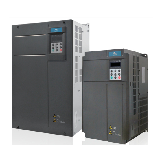
Page 16: Components Of The Is580
Chapter 2 Product Information 2.2 Components of the IS580 The IS580 series servo drives have two housing types, plastic housing and sheet metal housing, according to different voltage and power classes. Figure 2-2 Components of the IS580 of plastic housing (three-phase 380 to 480 V, IS580T020-R1-1 to…
-
Page 17
Chapter 2 Product Information IS580 User Manual Figure 2-4 Components of the IS580 of sheet metal housing (three-phase 380 to 480 V, IS580T080-R1-H-1 to IS580T210-R1-H-1) Front cover Inovance logo Operating panel Control board Filter capacitor Power terminals Housing — 16 -… -
Page 18: Technical Specifications
IS580 User Manual Chapter 2 Product Information 2.3 Technical Specifications Table 2-1 Technical specifications of the IS580 Item Description Standard Max. frequency 300 Hz functions Carrier frequency 1 to 8 kHz Input frequency resolution Digital setting: 0.01 Hz Analog setting: Max. frequency x 0.1% Control mode Closed-loop vector control (CLVC), voltage/frequency (V/F) control Startup torque…
-
Page 19
Chapter 2 Product Information IS580 User Manual — 18 -… -
Page 20: Chapter 3 Mechanical And Electrical Installation
Mechanical and Electrical Installation…
-
Page 21: Mechanical Installation
■ The mechanical clearance requirements for the IS580 vary with power classes of the servo drive. Figure 3-1 Mounting clearance of the IS580 Installation clearance requirements on the IS580 series servo drives of different power classes Hot air Power Class…
-
Page 22
Chapter 3 Mechanical and Electrical Installation The IS580 series servo drive dissipates heat from the bottom to the top. The drive of IS580T080-R1-H-1 to IS580T210-R1-H-1dissipates heat from the left to the right. When multiple servo drives are required to work together, install them side by side. -
Page 23
Chapter 3 Mechanical and Electrical Installation IS580 User Manual Embedded mounting the IS580 of plastic housing (IS580T020-R1-1 to IS580T070-R1-1) Figure 3-4 External hanging bracket for the IS580 of plastic housing External hanging bracket Figure 3-5 Embedded mounting of the IS580 of plastic housing Install the servo drive from the front of the control cabinet. -
Page 24
IS580 User Manual Chapter 3 Mechanical and Electrical Installation Surface mounting of the IS580 of sheet metal housing (IS580T080-R1-1 to IS580T210-R1-1) Figure 3-6 Surface mounting of the IS580 of sheet metal housing Install the servo drive from the front of the control cabinet. Back panel of the control cabinet Fix four screws. -
Page 25
Chapter 3 Mechanical and Electrical Installation IS580 User Manual Embedded mounting of the IS580 of sheet metal housing (IS580T080-R1-1 to IS580T210-R1-1) Figure 3-8 External hanging bracket for the IS580 of sheet metal housing External bracket External bracket Figure 3-9 Embedded mounting of the IS580 of sheet metal housing Install the servo drive from the front of the control cabinet. -
Page 26
IS580 User Manual Chapter 3 Mechanical and Electrical Installation Embedded mounting of the IS580 of sheet metal housing (IS580T080-R1-H-1 to IS580T210-R1-H-1) Figure 3-10 Embedded mounting from the cabinet front Back panel of the Installation effect Install the servo drive from the control cabinet front of the control cabinet M6 screw x 18… -
Page 27
3.1.4 Removal of the Front Cover For the IS580 series servo drives, you need to remove the front cover before wiring the main circuit and control circuit. The following figures show how to remove the front cover of the IS580. -
Page 28: Wiring Mode
Chapter 3 Mechanical and Electrical Installation 3.2 Wiring Mode The wiring of the IS580 series servo drive is shown in the foldout at the end of this chapter. 3.3 Main Circuit Terminals and Wiring Figure 3-15 Terminal arrangement of the main circuit…
-
Page 29: Control Circuit Terminals And Wiring
Chapter 3 Mechanical and Electrical Installation IS580 User Manual 3.4 Control Circuit Terminals and Wiring Figure 3-17 The control circuit terminal arrangement RJ45 KEYBOARD Terminal arrangement of the IS580 control board T/A1 T/B1 T/C1 T/A2 T/C2 T/A3 T/C3 AI1 AI2 AI3 GND 10V 13V GND AO1 AO2 GND COM DI1 DI2 DI3 DI4 DI5 COM OP 24V PTCP PTVN CANHCANL CGND 485B 485A Function Description of Jumpers of the IS580…
-
Page 30
IS580 User Manual Chapter 3 Mechanical and Electrical Installation Description of Control Circuit Terminals ■ Type Terminal Name Description Provide +10 V±10% power supply externally. Generally, it provides power supply to the external potentiometer with +10V-GND +10 V power supply resistance range of 1 to 5 kΩ. -
Page 31: Description Of Pg Card Terminals On The Is580
Chapter 3 Mechanical and Electrical Installation IS580 User Manual Type Terminal Name Description Voltage or current output is decided by jumper J4. Output range: 0–10 V/0–20 mA AO1-GND Analog output 1 12-bit resolution, correction accuracy 1%, maximum load resistance value ≤ 500 Ω Analog output Voltage or current output is decided by jumper J6.
-
Page 32
IS580 User Manual Chapter 3 Mechanical and Electrical Installation Figure 3-18 Connecting the PG card to the motor (1) POWER MOTOR COS- COS+ SIN- SIN+ REF- REF+ KTY- KTY+ PTC- PTC+ Figure 3-19 Connecting the PG card to the motor (2) Built-in PG card MF38PG4A1 Yellow-… -
Page 33: Wiring The External Braking Unit
Chapter 3 Mechanical and Electrical Installation IS580 User Manual 3.6 Wiring the External Braking Unit Two wiring methods are provided, differing in the wiring of braking resistor overheat protection. Wiring method 1: After the signal of the braking resistor overheat relay is sent, the power supply of the IS580 is cut off.
-
Page 34: Wiring Diagram Of System Application
IS580 User Manual Chapter 3 Mechanical and Electrical Installation Figure 3-21 Basic wiring method 2 Circuit breaker IS580 Braking unit servo drive P(+) - + In this wiring method, the braking unit is connected to COM on one side and DIx on the other side. The function code setting is as follows when the braking unit is connected to different DI terminals: DI1: F4-00 = 11;…
-
Page 35: Use Of The Operation Panel
Chapter 3 Mechanical and Electrical Installation IS580 User Manual 3.8 Use of the Operation Panel The IS580 has a built-in LED operation panel. An external LED operation panel can also be connected to the RJ45 interface of the IS580 by an 8-core flat cable. You can modify the parameters, monitor the working status and start or stop the IS580 by operating the operation panel, as shown in the following figure.
-
Page 36
IS580 User Manual Chapter 3 Mechanical and Electrical Installation FWD/REV • ON indicates reverse rotation, and OFF indicates forward rotation. TUNE/TC • When the indicator is ON, it indicates torque control mode. When the indicator is blinking slowly, it indicates the auto-tuning state. -
Page 37
Chapter 3 Mechanical and Electrical Installation IS580 User Manual 3.8.3 Viewing and Modifying Function Codes The operation panel of the IS580 adopts three-level menu. The three-level menu consists of function code group (Level I), function code (Level II), and function code setting value (level III), as shown in the following figure. -
Page 38
IS580 User Manual Chapter 3 Mechanical and Electrical Installation In the stop or running state, the operation panel can display multiple status parameters. In the stop state, you can press to view the parameters circularly. For details on the parameters that can be displayed, see the description of group U0. -
Page 39
Chapter 3 Mechanical and Electrical Installation IS580 User Manual 3.8.4 Password Setting The servo drive provides the user password protection function. The following figure shows how to set the password to 1234. Figure 3-27 Setting the password Status parameter (Default display) 1500 Return Switchover… -
Page 40
IS580 User Manual Chapter 3 Mechanical and Electrical Installation User-defined Group ■ The user-defined menu is set to facilitate viewing and modifying of commonly used function codes. In this mode, the display parameter uF3.02 indicates function code F3-02. You can also modify parameters in this mode as in common editing state. -
Page 41
Chapter 3 Mechanical and Electrical Installation IS580 User Manual In the non-oil pressure control mode, deleting function codes from the user-defined group is as shown in the following figure. Figure 3-29 Deleting function codes from the user-defined group User-defined mode (Only the user-defined function codes are available) uF1.03… -
Page 42
IS580 User Manual Chapter 3 Mechanical and Electrical Installation 3.8. 6 Starting or Stopping the Servo Drive Selecting the Start/Stop Command Source ■ There are three start/stop command sources, namely, operation panel control, terminal control, and communication control. You can select the command source in F0-02. Function Code Parameter Name Setting Range Description Default… -
Page 43
For details on the communication protocols, consult Inovance. 3.8.7 Setting the Running Frequency The IS580 supports two control modes: speed mode and oil pressure mode, set in A3-00. In the speed mode, there are six frequency setting sources, digital setting (UP/DOWN modification, non-retentive at power failure), (UP/DOWN modification, retentive at power failure), AI1, AI2, AI3, and communication setting. -
Page 44
90 kW and above Braking resistor 75 kW and below Braking unit MDBUN Braking resistor P(+) – – Braking resistor MDBUN Braking unit Breaker Contactor Loop magnetic ring MCCB MC (wind it a turn) Filter – Servo pump Three-phase AC COS- COS+ SIN-… -
Page 45: Chapter 4 Servo Pump Commissioning
Servo Pump Commissioning…
-
Page 46: Servo Pump Commissioning Flowchart
Chapter 4 Servo Pump Commissioning IS580 User Manual Chapter 4 Servo Pump Commissioning 4.1 Servo Pump Commissioning Flowchart The servo pump commissioning process mainly includes motor auto-tuning, motor trial running, and servo oil pressure commissioning, as shown in the following figure. Figure 4-1 Servo pump commissioning flowchart Start Control mode: A3-00 = 0…
-
Page 47: Motor Trial Running
IS580 User Manual Chapter 4 Servo Pump Commissioning 4.2 Motor Trial Running 4.2.1 Procedure of Motor Trial Running Step Parameter Setting Parameter Description Remarks 1. Set the control mode. A3-00 = 0 Non-hydraulic control mode Set the non-hydraulic control mode. 2.
-
Page 48
Chapter 4 Servo Pump Commissioning IS580 User Manual Motor Auto-tuning Setting ■ Auto-tuning Mode Function Code Setting Application After motor auto-tuning is completed, the value of F1-16 is restored No operation F1-16 = 0 to 0 automatically. This mode is used when the back EMF of the motor is known. Static auto-tuning 1 F1-16 = 1 The motor runs at a low speed during auto-tuning, and therefore,… -
Page 49
IS580 User Manual Chapter 4 Servo Pump Commissioning Motor Auto-tuning Procedure ■ Figure 4-2 Motor auto-tuning procedure Power on the servo drive. After motor auto-tuning is completed, Set F0-02 to 0 (Operation panel perform trial running: Set F0-08 to control) and F1-00 = 2 (PMSM). 5.00 (Hz), and Press RUN. -
Page 50: Application Commissioning Of Servo Pump
Chapter 4 Servo Pump Commissioning IS580 User Manual 4.3 Application Commissioning of Servo Pump 4.3.1 AI Zero Drift Auto Correction Step Function Code Setting Parameter Description Remarks 1. Set the command The operation panel control F0-02 = 0 The LOCAL/REMOT indicator is OFF. source.
-
Page 51
IS580 User Manual Chapter 4 Servo Pump Commissioning Function Code Parameter Name Setting F4-00 DI1 function selection 1: Forward RUN (FWD enabled) F4-01 DI2 function selection 48: Servo pump PID selection terminal 1 F4-02 DI3 function selection 53: Slave pump address selection terminal 1 F4-03 DI4 function selection 9: Fault reset (RESET) -
Page 52
Chapter 4 Servo Pump Commissioning IS580 User Manual Oil Presure PID Proportional Gain (A3-05, A3-11, A3-14, and A3-17) ■ The larger the proportional gain, the faster the system response. Too large setting will cause system oscillation, but too small setting will slow the system response. Figure 4-3 Relationship between the proportional gain and system response Pressure P pressure… -
Page 53
IS580 User Manual Chapter 4 Servo Pump Commissioning Oil Pressure Overshoot Suppression (A3-27/A4-16, A3-28/A4-17) ■ This function is used for pressure overshoot suppression at high speed. Overshoot suppression detection level (A3-27/A4-16) • The larger the value of the parameter is, the later the overshoot suppression starts, the poorer the suppression effect becomes, and the bigger the overshoot will be. -
Page 54
Chapter 4 Servo Pump Commissioning IS580 User Manual — 52 -… -
Page 55
Maintenance and Trouble-shooting… -
Page 56: Chapter 5 Maintenance And Troubleshooting
Chapter 5 Maintenance and Troubleshooting IS580 User Manual Chapter 5 Maintenance and Troubleshooting 5.1 Maintenance of the Servo Drive 5.1.1 Daily Maintenance The influence of the ambient temperature, humidity, dust and vibration will cause the aging of the devices in the servo drive, which may cause potential faults or reduce the service life of the servo drive.
-
Page 57: Warranty Agreement
Free warranty only applies to the servo drive itself. Inovance will provide 18-month warranty from date of manufacturing for the failure or damage under normal use conditions. If the equipment has been used for over 18 months, reasonable repair expenses will be charged.
-
Page 58: Troubleshooting
Before contacting Inovance for technical support, you can first determine the fault type, analyze the causes, and perform troubleshooting according to the description in this chapter. If the fault cannot be rectified, contact the agent or Inovance.
-
Page 59
IS5800 User Manual Chapter 5 Maintenance and Troubleshooting 5.3.1 Troubleshooting flowchart Figure 5-1 Err02 (Overcurrent during acceleration) Err02 Check whether the servo drive output circuit is Eliminate external faults. earthed or short circuited. V/F control Check whether motor auto-tuning Perform motor auto-tuning. is performed properly. -
Page 60
Check whether the braking unit and braking Install the braking unit and braking resistor are installed. resistor. Contact the agent or Inovance. Figure 5-3 Err04 (Overcurrent at constant speed) Err04 Eliminate external faults. Install Check whether the servo drive output circuit is an output reactor if the cable is earthed or has leakage current. -
Page 61
Install the braking unit and braking Check whether the braking unit and braking resistor. resistor are installed. Contact the agent or Inovance. Figure 5-5 Err06 (Overvoltage during deceleration) Err06 Check whether the input voltage of the Adjust the input voltage to the normal servo drive is too high. -
Page 62
Remove the external force or Check whether there is an external force to drive install a braking resistor. the motor during acceleration. Contact the agent or Inovance. Figure 5-7 Err09 (Undervoltage) Err09 Check whether instantaneous power failure occurs. Perform the reset operation. -
Page 63
Clear the air filter. Check whether the cooling fan is damaged. Replace the cooling fan. Contact the agent or Inovance. Check whether the module thermistor is damaged. Replace the thermistor. Check whether the inverter module is damaged. Replace the inverter module. -
Page 64
Check whether communication parameters Set the communication are set properly. parameters properly. Contact the agent or Inovance. Figure 5-14 Err17 (Contactor fault) Err17 Check whether the drive board and power Replace the drive board or supply are normal. -
Page 65
IS5800 User Manual Chapter 5 Maintenance and Troubleshooting Figure 5-15 Err18 (Current detection fault) Contact the agent or Inovance. Err18 Check whether hall devices are normal. Replace the hall devices. Check whether the drive board is normal. Replace the drive board. -
Page 66
Replace the servo drive. Figure 5-20 Err26 (Accumulative running time reached) Err26 Check whether F7-09 (Accumulative Contact the agent or Inovance. running time) is equal to or greater than F8-17 (Set accumulative running time) Do you want the servo drive to continue running? Stop the servo drive. -
Page 67
Increase the capacity level of the after increasing the capacity level of the servo drive. servo drive. Contact the agent or Inovance. Figure 5-23 Err42 (CAN communication interrupted) Err42 Set correct CAN communication Check whether the CAN communication parameters A2- parameters. -
Page 68
Eliminate the wiring fault. Check whether the encoder wiring is correct. Contact the agent Install the encoder correctly. or Inovance. Check whether the encoder installation is correct. Check whether the encoder becomes normal It is PG card fault. after the PG card is replaced. -
Page 69
Eliminate the power supply fault. pressure sensor is normal. Contact the agent Check whether the output of the pressure Replace the pressure sensor. or Inovance. sensor is normal. Check whether it it normal after the terminal It is terminal block fault. block is replaced. -
Page 70
Figure 5-30 Err59 (Back EMF auto-tuning fault) Err5 9 Contact the agent or Check motor parameters in group F1 are Set motor parameters correctly. Inovance. set correctly. Replace the motor and contact Replace with a motor of the same type to motor manufacturer to find the check whether the motor is demagnetized. -
Page 71: Symptoms And Diagnostics
1. Check the power input. servo drive. 2. Connect the 8-core cable again. 2. The 8-core cable connecting the 3. Contact the agent or Inovance. drive board and the control board is in poor contact. 3. Components inside the servo drive are damaged.
-
Page 72
The soft startup contactor is not 1. Check: power-on or running. closed. Whether the contactor cable is loose Whether the contactor is faulty Whether the contactor 24 V power supply is faulty. 2. Contact the agent or Inovance. — 70 -… -
Page 73
ISMG Servo Motor… -
Page 74: Chapter 6 Ismg Servo Motor (Voltage Class: 400 V)
Chapter 6 ISMG Servo Motor (Voltage Class: 400 V) IS580 User Manual Chapter 6 ISMG Servo Motor (Voltage Class: 400 V) 6.1 Designation Rules of the ISMG Servo Motor ISM G1- 30D 15C D- R1 3 1 F Mark Customized Requirement Mark Series No.
-
Page 75: Ismg Servo Motor Specification Parameters
IS580 User Manual Chapter 6 ISMG Servo Motor (Voltage Class: 400 V) 6.2 ISMG Servo Motor Specification Parameters 6.2.1 ISMG1 Servo Motor (200 x 200 Base/Forced Air Cooling) Specifications of the ISMG1 motor with forced air cooling Servo Motor Model Rated Torque Rated Motor Back EMF…
-
Page 76
Chapter 6 ISMG Servo Motor (Voltage Class: 400 V) IS580 User Manual 6.2.2 ISMG2 Servo Motor (266 x 266 Base/Forced Air Cooling) Specifications of the ISMG1 motor with forced air cooling Servo Motor Model Rated Torque Rated Motor Back EMF Rated Rated No-load… -
Page 77: Physical Appearance And Mounting Dimensions Of Ismg Servo Motor
IS580 User Manual Chapter 6 ISMG Servo Motor (Voltage Class: 400 V) 6.3 Physical Appearance and Mounting Dimensions of ISMG Servo Motor 6.3.1 ISMG1 Servo Motor (200 x 200 Base/Forced Air Cooling) Figure 6-1 Physical appearance and mounting dimensions of the ISMG1 servo motor (200 x 200 base/forced air cooling) Standard configuration: A-type round-end parallel key 12 x 8 x 56 Refer to GB/T 1096…
-
Page 78: Supporting Board Of Ismg Servo Motor Base
Chapter 6 ISMG Servo Motor (Voltage Class: 400 V) IS580 User Manual 6.3.2 ISMG2 Servo Motor (266 x 266 Base/Forced Air Cooling) Figure 6-2 Physical appearance and mounting dimensions of the ISMG2 servo motor (266 x 266 base/forced air cooling) Standard configuration: A-type round-end parallel key 14 x 9 x 90 Refer to GB/T1096 Table 6-2 Mounting dimensions of the ISMG2 servo motor (266 x 266 base/forced air cooling)
-
Page 79: Wiring Of The Ismg Servo Motor
IS580 User Manual Chapter 6 ISMG Servo Motor (Voltage Class: 400 V) 6.5 Wiring of the ISMG Servo Motor 6.5.1 Terminals of PCB Board The signal types of the terminals are defined on the PCB board. AC1 and AC2 are power supply (single-phase 220 V) to the cooling fan.
-
Page 80: Cleaning The Cooling Fan Of The Servo Motor
Chapter 6 ISMG Servo Motor (Voltage Class: 400 V) IS580 User Manual 6.6 Cleaning the Cooling Fan of the Servo Motor The estimated service life of the cooling fan of the servo motor is 40000 hours. On the condition that the cooling fan runs continuously at full speed, rated voltage and 40°C ambient temperature, after the cooling fan is jammed with foreign matters, the performance of the cooling fan degrades and the air volume reduces.
-
Page 81
Selection… -
Page 82: Chapter 7 Selection
Chapter 7 Selection IS580 User Manual Chapter 7 Selection 7.1 Technical Data of the IS580 Model Power Capacity Input Current Output Current Adaptable Motor Thermal Power Consumption (kW) (kVA) (kW, HP) Three-phase 440 V, 50/60 Hz IS580T020-R1-1 36.3 0.445 IS580T030-R1-1 45.1 0.553 IS580T035-R1-1…
-
Page 83: Selection Of Braking Unit And Braking Resistor
IS580 User Manual Chapter 7 Selection 7.2 Selection of Braking Unit and Braking Resistor Servo drive Model Recommended Recommended Braking Unit Remark Power of Braking Resistance of Resistor Braking Resistor Three-phase 380 to 480 V IS580T020-R1-1 800 W ≥ 43 Ω Built-in IS580T030-R1-1 1000 W…
-
Page 84: Mounting Dimensions Of The Is580
Chapter 7 Selection IS580 User Manual Servo drive Model Servo drive MCCB Contactor Cable of Input Cable of Output Cable of Main Circuit Rated Input Side Main Side Main Control Grounding Current Circuit (mm Circuit (mm Circuit (mm Cable (mm IS580T100-R1-1 106.00 0.75…
-
Page 85
IS580 User Manual Chapter 7 Selection Figure 7-2 Mounting dimensions of IS580 sheet metal housing (IS580T080-R1-1 to IS580T210-R1-1) Table 7-1 Mounting dimensions of IS580 sheet metal housing (IS580T080-R1-1 to IS580T210-R1-1) Servo drive Model Mounting Hole Overall Dimensions (mm) Mounting Weight (mm) Hole Diameter (kg) -
Page 86
Chapter 7 Selection IS580 User Manual Figure 7-3 Mounting dimensions of IS580 sheet metal housing (IS580T080-R1-H-1 to IS580T210-R1-H-1) 272.5 G1/2 internal thread 18- 7 — 84 -… -
Page 87: Mounting Dimensions Of Power Terminals And Recommended Cable Diameter
IS580 User Manual Chapter 7 Selection 7.5 Mounting Dimensions of Power Terminals and Recommended Cable Diameter Note • The data and models recommended in the table are for reference only. The diameter of the cable the use selects must not exceed the terminal dimensions in the figure. •…
-
Page 88
Chapter 7 Selection IS580 User Manual Table 7-3 Cable dimensions and tightening torque of IS580T050/070 Servo drive Model Rated Input Recommended Cable Tightening Torque Recommended Current (A) Diameter (mm (N·m) Cable Lug Model IS580T050-R1-1 GTNR16-6 IS580T070-R1-1 GTNR25-6 Figure 7-6 Terminal dimensions of IS580T080/100 26.8 24.8 POWER… -
Page 89
IS580 User Manual Chapter 7 Selection Table 7-5 Cable dimensions and tightening torque of IS580T140/170/210 Servo drive Model Rated Input Recommended Cable Tightening Torque Recommended Current (A) Diameter (mm2) (N·m) Cable Lug Model IS580T140-R1-1 35.0 GTNR70-12 IS580T140-R1-H-1 IS580T170-R1-1 35.0 GTNR70-12 IS580T170-R1-H-1 IS580T210-R1-1 35.0… -
Page 90
Chapter 7 Selection IS580 User Manual Table 7-7 Models and dimensions of the GTNR series cable lugs Cable Lug Model D Crimping Tool GTNR1.5-5 16.0 RYO-8 YYT-8 GTNR2.5-4 18.0 RYO-14 GTNR2.5-5 20.0 GTNR2.5-6 10.2 GTNR4-5 10.0 20.0 GTNR4-6 GTNR6-5 10.0 23.0 GTNR6-6 26.0… -
Page 91: Mounting Dimensions Of Optional Parts
IS580 User Manual Chapter 7 Selection 7.6 Mounting Dimensions of Optional Parts 7.6.1 Mounting Dimensions of the External Braking Unit Note The servo drive of IS580T170-R1-1 and above has the built-in DC reactor. Figure 7-11 Physical appearance and mounting dimensions of the MDBUN series braking unit 7.6.2 Physical Dimensions of External Operation Panel Figure 7-12 Physical dimensions of external operation panel 27.0…
-
Page 92
Chapter 7 Selection IS580 User Manual — 90 -… -
Page 94: Definition Of Terms
Chapter 8 EMC IS580 User Manual Chapter 8 EMC 8.1 Definition of Terms ■ Electromagnetic compatibility (EMC) describes the ability of electronic and electrical devices or systems to work properly in the electromagnetic environment and not to generate electromagnetic interference that influences other local devices or systems.
-
Page 95: Introduction To Emc Standard
2006/95/EC EN 61800-5-1 93/68/EEC The IS580 series servo drive satisfies the requirements of standard EN 61800-3. 2004 Category C2. The Servo drives are applied to both the first environment and the second environment. 8.2.3 Installation Environment The system manufacturer using the servo drive is responsible for compliance of the system with the European EMC directive.
-
Page 96: Selection Of Peripheral Emc Devices
The IS580 series servo drive satisfies the requirements of category C2 only with an EMC filter installed on the power input side. The installation precautions are as follows: Strictly comply with the ratings when using the EMC filter.
-
Page 97
IS580 User Manual Chapter 8 EMC The following table lists the recommended manufacturers and models of EMC filters for the IS580 series servo drive. Select a proper one based on actual requirements. Table 8-1 Recommended manufacturers and models of EMC filters… -
Page 98
Chapter 8 EMC IS580 User Manual Selection of the simple EMC filter • Servo Drive Model Simple EMC Filter Rated Current Overall Dimensions Mounting Dimensions Filter Model (Length x Width x Height) (Mounting Length x Mounting Width) IS580T020-R1-1 DL65EB1/10 218 x 140 x 80 184 x 112 IS580T030-R1-1 IS580T035-R1-1… -
Page 99
The following table lists the recommended manufacturers and models of input reactors. Table 8-2 Recommended manufacturers and models of AC input reactors Servo drive Model AC Input Reactor Model Reactor Rated Current (Inovance) IS580T020-R1-1 MD-ACL-40-4T-153-2% IS580T030-R1-1 MD-ACL-50-4T-183-2% IS580T035-R1-1… -
Page 100
280 to 690 The following table lists the recommended manufacturer and models of AC output reactors. Table 8-4 Recommended manufacturer and models of AC output reactors Servo drive Model AC Output Reactor Model Reactor Rated Current (Inovance) IS580T020-R1-1 MD-OCL-30-4T-113-1% IS580T030-R1-1 MD-OCL-40-4T-153-1% IS580T035-R1-1… -
Page 101: Shielded Cable
IS580 User Manual Chapter 8 EMC 8.4 Shielded Cable 8.4.1 Requirements for Shielded Cable The shielded cable must be used to satisfy the EMC requirements of CE marking. Shielded cables are classified into three-conductor cable and four-conductor cable. If conductivity of the cable shield is not sufficient, add an independent PE cable, or use a four-conductor cable, of which one phase conductor is PE cable.
-
Page 102
Chapter 8 EMC IS580 User Manual The installation precautions are as follows: Symmetrical shielded cable is recommended. The four-conductor shielded cable can also be used as an input cable. The motor cable and PE shielded conducting wire (twisted shielded) should be as short as possible to reduce electromagnetic radiation and external stray current and capacitive current of the cable. -
Page 103: Solutions To Common Emc Interference Problems
IS580 User Manual Chapter 8 EMC 8.5 Solutions to Common EMC Interference Problems The servo drive generates very strong interference. Although EMC measures are taken, the interference may still exist due to improper cabling or grounding during use. When the servo drive interferes with other devices, adopt the following solutions.
-
Page 104
Chapter 8 EMC IS580 User Manual — 102 -… -
Page 105
Function Code Table… -
Page 106: Chapter 9 Function Code Table
Chapter 9 Function Code Table IS580 User Manual Chapter 9 Function Code Table Function Name LED Display Setting Range Min. Unit Default Property Code Group U0: View Servo Drive Parameters U0-00 Running frequency Running frequency 0.00 Hz to maximum ● frequency (F0-10) U0-01 Set frequency…
-
Page 107
IS580 User Manual Chapter 9 Function Code Table Function Name LED Display Setting Range Min. Unit Default Property Code U1-03 Motor speed Motor speed -9999 to 30000 RPM ● U1-04 AI1 voltage AI1 voltage -10.00 to 10.000 V ● U1-05 AI2 voltage AI2 voltage -10.00 to 10.000 V… -
Page 108
Chapter 9 Function Code Table IS580 User Manual Function Name LED Display Setting Range Min. Unit Default Property Code A1-02 Encoder installation Encoder installation 0.0° to 359.9° 0.1° 0.0° ☆ angle angle A1-03 Inversion of feedback Inversion of feedback 0: Consistent ★… -
Page 109
IS580 User Manual Chapter 9 Function Code Table Function Name LED Display Setting Range Min. Unit Default Property Code A3-02 System oil pressure System oil pressure 0.0 kg/cm to maximum oil 0.0 kg/cm 175.0 kg/ ☆ pressure (A3-03) A3-03 Max. oil pressure Max. -
Page 110
Chapter 9 Function Code Table IS580 User Manual Function Name LED Display Setting Range Min. Unit Default Property Code A3-26 S-curve fall filter time of S-curve fall filter time of 0.000s to 1.000s 0.001s 0.020s ☆ set oil pressure set oil pressure A3-27 Overshoot suppression Overshoot suppression… -
Page 111
IS580 User Manual Chapter 9 Function Code Table Function Name LED Display Setting Range Min. Unit Default Property Code A3-43 Pressure deviation of Pressure deviation of 0 to 50.0 kg 0.1 kg 5.0 kg ☆ slave pump not working slave pump not working in the CAN multi-pump in the CAN multi-pump mode… -
Page 112
Chapter 9 Function Code Table IS580 User Manual Function Name LED Display Setting Range Min. Unit Default Property Code A4-09 Long-time running Long-time running 0.001s to 5.000s 0.001s 0.000s ☆ protective time of protective time of reverse pressure relief reverse pressure relief A4-10 Injection S-curve rise Injection S-curve rise… -
Page 113
IS580 User Manual Chapter 9 Function Code Table Function Name LED Display Setting Range Min. Unit Default Property Code F0-02 Command source Command source 0: Operation panel (LED ☆ selection selection OFF) 1: Terminal (LED ON) 2: Communication setting (LED blinking) F0-03 Main frequency source Main frequency source… -
Page 114
Chapter 9 Function Code Table IS580 User Manual Function Name LED Display Setting Range Min. Unit Default Property Code F0-17 Acceleration time 1 Acceleration time 1 0.0s to 6500.0s 0.1s 20.0s ☆ F0-18 Deceleration time 1 Deceleration time 1 0.0s to 6500.0s 0.1s 20.0s ☆… -
Page 115
IS580 User Manual Chapter 9 Function Code Table Function Name LED Display Setting Range Min. Unit Default Property Code F1-16 Motor auto-tuning mode Motor auto-tuning mode 0: No operation ★ 1: No-load static auto-tuning 2: No-load dynamic auto- tuning, rotating at high speed in reverse direction 3: With-load static auto- tuning… -
Page 116
Chapter 9 Function Code Table IS580 User Manual Function Name LED Display Setting Range Min. Unit Default Property Code F2-11 Torque filter bandwidth Torque filter bandwidth 0 to 1500 Hz 1 Hz 500 Hz ☆ F2-12 Reserved ★ F2-13 Current loop low-speed Current loop low-speed 0.2 to 5.0 ★… -
Page 117
IS580 User Manual Chapter 9 Function Code Table Function Name LED Display Setting Range Min. Unit Default Property Code F4-05 to Reserved 51: Slave pump enabled as ★ F4-14 master pump 52: Switchover from pressure mode to speed mode 53: Slave pump address selection terminal 1 54: Slave pump address selection terminal 2… -
Page 118
Chapter 9 Function Code Table IS580 User Manual Function Name LED Display Setting Range Min. Unit Default Property Code F4-33 to Reserved ☆ F4-58 Group F5: Output Terminals F5-00 Reserved ☆ F5-01 Control board relay (T/ Control board relay (T/ 0: No output ☆… -
Page 119
IS580 User Manual Chapter 9 Function Code Table Function Name LED Display Setting Range Min. Unit Default Property Code F5-11 AO2 output selection AO2 output selection 2: Output current ☆ 3: Output torque 4: Output power 5: Output voltage 6: Reserved 7: AI1 8: AI2 9: AI3… -
Page 120
Chapter 9 Function Code Table IS580 User Manual Function Name LED Display Setting Range Min. Unit Default Property Code F7-06 Load speed display Load speed display 0.0001 to 6.5000 0.0001 1.0000 ☆ coefficient coefficient F7-07 Heatsink temperature 1 Heatsink temperature 1 0.0°C to 100°C 1°C ●… -
Page 121
IS580 User Manual Chapter 9 Function Code Table Function Name LED Display Setting Range Min. Unit Default Property Code F9-14 Runaway speed Runaway speed 0.50 to 50.00 Hz 0.01 Hz 10.00 Hz ☆ deviation deviation F9-15 Detection time of Detection time of 0.1s to 20.0s 0.1s 10.0s… -
Page 122
Chapter 9 Function Code Table IS580 User Manual Function Name LED Display Setting Range Min. Unit Default Property Code F9-20 Latest fault type Latest fault type 22: Reserved (Err22) ☆ 23: : Short circuit to ground (Err23) 24 and 25: Reserved 26: Accumulative running time reached 27: Business running time… -
Page 123
IS580 User Manual Chapter 9 Function Code Table Function Name LED Display Setting Range Min. Unit Default Property Code F9-22 Current at fault Current at fault 0.1 A ● occurrence occurrence F9-23 Bus voltage at fault Bus voltage at fault 0.1 V ●… -
Page 124
FD-05 Communication Communication protocol 0: Standard Modbus ☆ protocol protocol, used for host computer parameter reading/writing and running control 1: Inovance private protocol, used for communication with background oscilloscope Group FP: User Password FP-00 User password User password 0–65535 ☆… -
Page 125
Appendix… -
Page 126: Appendix A Leakage Current Suppression Solution And Leakage Protector Selection
Chapter 10 Appendix IS580 User Manual Appendix A Leakage Current Suppression Solution and Leakage Protector Selection Note In the following tables, • «-» indicates that the leakage current suppression solution does not cover the power. • The residual current circuit breaker (RCCB), RCD and leakage protector indicate the same concept. Servo Drive Model Solution 1: Require Leakage Current During Running <…
-
Page 127
IS580 User Manual Chapter 10 Appendix Servo Drive Solution 1: Require Leakage Current During Running < 100 mA (Use Wind the Magnetic Ring Three Model Turns and Use the Safety Capacitance Box). Leakage Leakage Magnetic Safety Installation Wiring Diagram Leakage Protector Protector Ring Model… -
Page 128
Chapter 10 Appendix IS580 User Manual Servo Drive Model Solution 3: Require Leakage Current During Running < 200 mA (Wind the Magnetic Ring One Turn and Use the Safety Capacitance Box). Magnetic Ring Installation Wiring Diagram Leakage Protector Model Selection Reserved DY644020H For selection of the safety capacitance box, refer to… -
Page 129
IS580 User Manual Chapter 10 Appendix Servo Drive Model Solution 4: Require Leakage Current During Running Reducing 50% (Wind the Input or Output Magnetic Ring Three Turns). Magnetic Ring Model Installation Wiring Diagram Leakage Protector Selection Reserved DY644020H For the wiring diagram of winding the output Action current UVW cable three turns, for the wiring diagram I△n… -
Page 130
Chapter 10 Appendix IS580 User Manual Servo Drive Model Solution 5: Require Leakage Current During Running Reducing 25% (Wind the Input or Output Magnetic Ring One Turn). Magnetic Ring Model Installation Wiring Diagram Leakage Protector Selection Reserved DY644020H I△n Action current ≥… -
Page 131: Appendix B Multi-Pump Control Of Imm
IS580 User Manual Chapter 10 Appendix Appendix B Multi-pump Control of IMM B.1 Parallel Pump Control The parallel pump control is classified into multi-pump convergent flow and multi-pump distributed flow. The multi-pump convergent flow • A servo drive is used as the master drive, and the other drives are used as slave drives connected in parallel. The host computer outputs a set of flow and pressure analog signals.
-
Page 132
Chapter 10 Appendix IS580 User Manual Note • For detailed wiring and CAN communication wiring, refer to the foldouts at the end of this chapter. • For the parameter setting, refer to the following related parameter setting part. • You can ensure the same motor speed through the communication. The following figure shows the multi-pump distributed flow structure chart. -
Page 133: Multi-Pump Control Mode
IS580 User Manual Chapter 10 Appendix B.2 Multi-pump Control Mode Function Code Parameter Name Setting Range A2-03 CAN multi-pump mode 0: Multi-pump 1 (old mode) 1: Multi-pump 2 (new mode) Multi-pump 1 • This mode is the old mode and is applicable to simple multi-pump control. When the slave pump is switched over to the master pump, the slave pump cannot be controlled.
-
Page 134
Chapter 10 Appendix IS580 User Manual CAN Communication Wiring ■ The CAN bus connection of all pumps is shown in the following figure. Figure B-3 CAN bus connection of all pumps Slave drive 2 Master drive Slave drive 1 CANL CANL CANL CANH… -
Page 135
IS580 User Manual Chapter 10 Appendix For example: Condition 1: Suppose the max. pressure holding speed of the master is 50 rpm/min., the max. speed of the master is 2000 rpm/min., and the max. speed of the slave is 2000 rpm/min. Condition 2: At pressure hoding, the master works and the slave stops. -
Page 136: Parameter Setting On Master Drive
Chapter 10 Appendix IS580 User Manual B.3 Parameter Setting on Master Drive Multi-pump mode 1 (A2-03 = 0) • The parameter setting is simple. For all servo drives, allocate a DI terminal for the 50# function and set it to Function Code Parameter Name Setting Description…
-
Page 137: Parameter Setting On Slave Drive
IS580 User Manual Chapter 10 Appendix Description of slave pump address setting • The LED display of the slave pump address setting is as follows: Note • The numbers in the LED display correspond to the slave pump address station No. •…
-
Page 138: Applications Of Multi-Pump Convergent And Distributed Flow Control
Chapter 10 Appendix IS580 User Manual Multi-pump mode 2 (A2-03 = 1) • The following table lists the parameter setting of the slave drive. Perform the same parameter setting as you do in the common servo pump mode. Function Code Parameter Name Setting Description A2-01…
-
Page 139
IS580 User Manual Chapter 10 Appendix Note • Because the 1# pump is always the master pump and the 2# pump alaways the slave pump, directly short the DI terminal set for the 50# function. • The 3# pump switches over to the master pump in the following combination 2, which requires an external switchover signal. -
Page 140
Chapter 10 Appendix IS580 User Manual B.5.2 Multi-pump Mode 2 (A2-03 = 1) For example, the IMM servo pump system consists of four pumps with the address set as 1#, 2#, 3# and 4#. There are the follwoing three combinations: Combination 1: 4-pump convergent flow •… -
Page 141
IS580 User Manual Chapter 10 Appendix The 1# pump is the master pump, and the 2#, 3# and 4# pumps are slave pumps. The setting of address of corresponding slave pumps in A2-04 is as follows: Combination 2: 2+2 combination for distributed flow control ■… -
Page 142
Chapter 10 Appendix IS580 User Manual In this combination, the 1# pump and 3# pump are the master pumps. The slave pump changes and the address of the slave pump needs to be set. The slave pump of the 1# master pump is 2# pump. The setting of the slave pump address in A2-05 is as follows: The slave pump of the 3# master pump is 4# pump. -
Page 143: Fault Description
Check whether a fault occurs on the slave. Eliminate the slave fault. Check whether the CAN Eliminate connection fault. Contact the agent or communication connection is wrong. Inovance. Check whether it becomes normal after It is the terminal board fault. replacing the terminal board. — 141 -…
-
Page 144
Check whether more than one drive suffers fault. station No. fault Check whether the CAN Contact the agent or Eliminate connection fault. communication connection is wrong. Inovance. Check whether it becomes normal after It is the terminal board fault. replacing the terminal board. — 142 -… -
Page 145
Wiring of main circuit and control terminals: Filter Filter Loop magnetic ring Loop magnetic ring MCCB MCCB (Wiring of the braking circuit) (wind it a turn.) Loop magnetic ring (wind it a turn.) (wind it a turn.) Loop magnetic ring (wind it a turn.) (Wiring of braking circuit) Master drive Slave drive… -
Page 146
Wiring of main circuit and control terminals: Filter Filter Loop magnetic ring MCCB MCCB Loop magnetic ring (Wiring of the braking circuit) Wiring of braking circuit (wind it a turn) Loop magnetic ring (wind it a turn) Loop magnetic ring (wind it a turn.) (wind it a turn.) Master drive Slave drive… -
Page 147
Wiring of main circuit and control terminals: Filter Filter Loop magnetic ring Loop magnetic ring MCCB MCCB (Wiring of the braking circuit) (Wiring of braking circuit) Loop magnetic ring (wind it a turn) (wind it a turn) (wind it a turn.) Loop magnetic ring (wind it a turn.) Master drive Slave drive… -
Page 148
Wiring of main circuit and control terminals: Filter Filter Loop magnetic ring Loop magnetic ring MCCB MCCB (Wiring of the braking circuit) (Wiring of braking circuit) (wind it a turn.) Loop magnetic ring (wind it a turn.) (wind it a turn.) Loop magnetic ring (wind it a turn.) Master drive Slave drive… -
Page 149
If there is any failure or damage to the product, please correctly fill out the Product Warranty Card in detail. The maintenance fee is charged according to the latest Maintenance Price List of Inovance. The Product Warranty Card is not re-issued. Please keep the card and present it to the maintenance personnel when asking for maintenance. -
Page 150: Product Warranty Card
Product Warranty Card Address: Customer information Contact person: Company name: Postcode: Tel or Email: Product model: Serial No (Attach here): Product information Name Supplier who supplied you the unit Failure Description (eg. Fault code) Maintenance personnel:…
Specifications:1495/1495312-is580_series.pdf file (08 Jun 2023) |
Accompanying Data:
Inovance IS580 Series Servo Drives PDF Operation & User’s Manual (Updated: Thursday 8th of June 2023 07:13:57 AM)
Rating: 4.4 (rated by 92 users)
Compatible devices: IS620P Series, Alpha 5, iPOS360 VX-CAN Series, IS300S002-C, SV660N Series, SV820N Series, BD-E Series, ATE ZONE 2-22.
Recommended Documentation:
Text Version of Operation & User’s Manual
(Ocr-Read Summary of Contents of some pages of the Inovance IS580 Series Document (Main Content), UPD: 08 June 2023)
-
27, 5 Parameter Table — 25 — Para� No� Para� Name Setting Range Unit Default Property A3-26 Pressure command s-curve decelera…
-
48, Inovance IS580 Series 6 Troubleshooting — 46 — Output phase to phase or phase to ground short -circuit? auto tuning succeeds? Deceleration time too short? Fix the wrong wirings Conduct auto tuning Increase the time Overc…
-
62, 7 ISMG Servo Motor — 60 — 7� ISMG Servo Motor 7�1 Designation Rules ISM G1- 30D 15C D-R1 3 1 F ISM ISM Series servo motor Mark Series No� Mark Voltage Class X Naturally ventilated Mark C…
-
53, 6 Troubleshooting — 51 — Surroundings too hot? Air passage are stuffed up? Fan is broken? Lower the temperature of surroudings Cle…
-
43, Inovance IS580 Series 5 Parameter Table — 41 — Para� No� Para� Name Setting range Unit U0-49 Off-line times of can bus 0 to 65535 1 U…
-
32, Inovance IS580 Series 5 Parameter Table — 30 — Para� No� Para� Name Setting Range Unit Default Property F3-23 Voltage limit selection 0 to 1 1 1 ★ F3-24 Frequency gain for voltage limit 0 to 100 1 30 …
-
6, 1 Product Information — 5 — 1.2 General Specications Voltage class Three-phase 380 to 480 VAC Model: IS580Txxx…
-
36, 5 Parameter Table — 34 — Para� No� Para� Name Setting Range Unit Default Property F9-18 The third last fault 0: no fault 1: reserved 2: overcurrent (E02) 3: overc…
-
Inovance IS580 Series User Manual
-
Inovance IS580 Series User Guide
-
Inovance IS580 Series PDF Manual
-
Inovance IS580 Series Owner’s Manuals
Recommended: GS790 — 19″ CRT Display, 3226, FHM


-
Siemens SINAMICS S210
s Produktinformation A5E44420850 AB Edition 07/2018 Diese Produktinformation ist gültig für die Betriebsanleitung A5E41702836A AB, Ausgabe 07/2018 Fehlerhafte Anzeige von Meldungstexten im Webserver In manchen Meldungen taucht irrtümlicherweise ein Verweis auf das Listenhandbuch auf. Die Meldungen sind beim S21 …
SINAMICS S210 6
-
Festo CMMT-AS-C7/12-11A-P3-S1
CMMT-AS-C7/12-11A-P3-S1Servo driveFesto SE & Co. KGRuiter Straße 8273734 EsslingenDeutschland+49 711 347-0 www.festo.comOperating instructions | Installation, Safety sub-function81651062021-12c[8165108]Translation of the original instructions© 2021 all rights reserved to Festo SE & Co. KGBiSS®, EnDat®, Eth …
CMMT-AS-C7/12-11A-P3-S1 16
-
Kinco 2S
V2.0 1 Kinco 2S 系列伺服驱动器使用指南(中英文)V2.0 感谢您使用 Kinco 伺服产品!Kinco 系列不同型号产品的配件各不相同,收到产品后建议您对产品进行确认。 1. 请根据机身或包装盒上的铭牌信息确认驱动器型号与您所订购的型号是� …
2S 30
-
YASKAWA Sigma-V Series
MANUAL NO. SIEP S800000 88DOutlinePanel OperatorWiring and ConnectionTrial OperationOperationAdjustmentsUtility Functions (Fn) Monitor Displays (Un) Fully-closed Loop ControlTroubleshootingAppendix1234567891011SGDV-H, -J SERVOPACKSGDV-COA ConverterSGMVV ServomotorRot …
Sigma-V Series 434
Additional Information:
Popular Right Now:
Operating Impressions, Questions and Answers:
Каталоги, Инструкции, Программное обеспечение
Инструкции по эксплуатации Inovance
Описания по HMI-панелям Inovance
ПЛК, HMI, BUS — контроллеры Inovance
Модули ввода-вывода (IO modules) Inovance
Описание Ethercat устройств для подгрузки в CoDesys для продукции Inovace
Программное обеспечение

Программное обеспечение для настройки AMAC контроллеров — InoProShop V1
(Архив, zip, 853 Мб)
Preface
Advantages
■
Compared with the IS300, the IS580 has improvements in the following aspects:
Improvement
More stable pressure
Faster pressure and speed
response
Higher injection molding
product consistency
Smaller size
Wide voltage range design
Built-in DC reactor
Built-in braking unit and
related protective function
Longer serving life
Cooling fan drive circuit
protection
Complete protective
functions
Complete EMC solution
Product Checking
■
Upon unpacking, check:
Whether the nameplate model and the drive ratings are consistent with your order. The box contains the servo
•
drive, certificate of conformity, user manual and warranty card.
Whether the servo drive is damaged during transportation. If you find any omission or damage, contact
•
Inovance or your supplier immediately.
First-time Use
■
For the users who use this product for the first time, read the manual carefully. If you have any problem concerning
the functions or performance, contact the technical support personnel of Inovance to ensure correct use.
Description
The pressure fluctuation is smaller. The stability obvious at high pressure and low speed.
The pressure and speed responsiveness improves, satisfying the quick response
requirements of the quick hydraulic IMM.
The IS580 sees a rise in the qualified rate of the injection moudling products, especially the
quick injection molding products.
The IS580 is over 40% smaller than the IS300 for the same power class.
Rated voltage input: 380 to 480 V, wide voltage range: 323 to 528 V
The IS580 of 30 kW and above have built-in DC reactor.
The power class of the IS580 with built-in braking unit extends to 75 kW (optional for the
models of 90 kW above). The protective functions including braking resistor short-circuit,
braking circuit overcurrent, brake pipe overload and brake pipe shoot-through.
The bus capacitor has high disposition and long servicing life.
When short-circuit occurs on the cooling fan, the cooling fan drive circuit provides
protection.
The whole series of IS580 drives have the protections on short-circuit to ground and pre-
charge relay (contactor) close fault.
Complete EMC solution (including optional EMI filter, common mode rejector / zero-phase
reactor and simple filter) could be provided to satisfy the actual application and certification
requirements.
— 2 —
IS580 User Manual

IS580 User Manual
Preface
Preface
Thank you for purchasing the IS580 series servo drive developed and manufactured by Inovance.
The IS580 is an upgrade product compared with the IS300 series servo drive. It is specially designed to drive the
permanent magnet synchronous motor (PMSM) and implement high-performance vector control of the PMSM. By
integrating the process control during driving of the injection molding machine (IMM), such as precise control of
injection speed and pressure holding, and stability control during cooperation with the IMM controller, the IS580 can
well control the servo pump and provide general-purpose servo functions. The IS580 is highly cost-effective and
reliable. It has obvious energy saving effect compared with traditional IMM control mode.
It is applicable to plastic molding, pipe extrusion, shoe making, rubber producing, and metal casting. Compared
with the IS300, the IS580 features better oil pressure control performance, faster pressure and speed response,
smaller steady pressure fluctuation and smaller size.
This manual is a guideline for the selection, installation, parameter setting, on-site commissioning and
troubleshooting of the IS580 servo drive. It is only applicable to the IS580****-**-1 series servo drives.
Before using the servo drive, read this manual carefully to have a thorough understanding of the product. Keep the
manual well and forward it to end users with the product.
Note
•• The drawings in the manual are sometimes shown without covers or protective guards. Remember to
install the covers or protective guards as specified first, and then perform operations in accordance with
the instructions.
•• The drawings in the manual are shown for description only and may not match the product you
purchased.
•• The instructions are subject to change, without notice, due to product upgrade, specification
modification as well as efforts to increase the accuracy and convenience of the manual.
•• Contact our agents or customer service center if you have any problem during the use.
Note
This user manual is only applicable to the IS580****-**-1 series servo drives.
-1-
Preface
IS580 User Manual
Introduction
■■
Advantages
Compared with the IS300, the IS580 has improvements in the following aspects:
Improvement
Description
More stable pressure
The pressure fluctuation is smaller. The stability obvious at high pressure and low speed.
Faster pressure and speed The pressure and speed responsiveness improves, satisfying the quick response
response
requirements of the quick hydraulic IMM.
Higher injection molding
product consistency
The IS580 sees a rise in the qualified rate of the injection moudling products, especially the
quick injection molding products.
Smaller size
The IS580 is over 40% smaller than the IS300 for the same power class.
Wide voltage range design
Rated voltage input: 380 to 480 V, wide voltage range: 323 to 528 V
Built-in DC reactor
The IS580 of 30 kW and above have built-in DC reactor.
Built-in braking unit and
related protective function
The power class of the IS580 with built-in braking unit extends to 75 kW (optional for the
models of 90 kW above). The protective functions including braking resistor short-circuit,
braking circuit overcurrent, brake pipe overload and brake pipe shoot-through.
Longer serving life
The bus capacitor has high disposition and long servicing life.
Cooling fan drive circuit
protection
When short-circuit occurs on the cooling fan, the cooling fan drive circuit provides
protection.
Complete protective
functions
The whole series of IS580 drives have the protections on short-circuit to ground and precharge relay (contactor) close fault.
Complete EMC solution
Complete EMC solution (including optional EMI filter, common mode rejector / zero-phase
reactor and simple filter) could be provided to satisfy the actual application and certification
requirements.
■■
Product Checking
Upon unpacking, check:
••
Whether the nameplate model and the drive ratings are consistent with your order. The box contains the servo
drive, certificate of conformity, user manual and warranty card.
••
Whether the servo drive is damaged during transportation. If you find any omission or damage, contact
Inovance or your supplier immediately.
■■
First-time Use
For the users who use this product for the first time, read the manual carefully. If you have any problem concerning
the functions or performance, contact the technical support personnel of Inovance to ensure correct use.
-2-
IS580 User Manual
■■
Preface
Standard Compliant
The IS580 series servo drive complies with the international standards listed in the following table.
Directive
Directive Code
Standard
EMC directive
2004/108/EC
EN 61800-3
EN 55011
EN 61000-6-2
LVD directive
2006/95/EC
EN 61800-5-1
93/68/EEC
The IS580 series servo drive complies with the requirements of standard IEC/EN 61800-3 on the condition of
correct installation and use by following the instructions in sections 8.3.2 and 8.3.5.
-3-
Preface
IS580 User Manual
HMI
Use within the allowable power supply specification
of the servo drive.
Three-phase AC power supply
D O 1 Pump enable
D O 2 PID selection terminal 1
Molded case circuit breaker
(MCCB) or earth leakage circuit
breaker (ELCB)
Slave pump address
D O 3 selection terminal 1
D O 4 Fault reset
Select a proper circuit breaker to resist large in-rush
current that flows into the servo drive at power-on.
D O 5 CAN communication enable
To ensure safety, use an electromagnetic contactor.
Do not use it to start or stop the servo drive because
such operation reduces the service life of the servo
drive.
Electromagnetic contactor
COM
(multi-pump convergent flow)
A I 1 Current oil pressure detection: -10 to 10 V
RUN
LOCAL/ REMOT
Hz
RPM
A
PRG
FED / REV
%
A I 2 Current flow detection: -10 to 10 V
TUNE /TC
GND
V
ENTER
QUICK
RUN
Noise filter on input side
Reduce the electromagnetic
interference on the input side.
MF.K
STOP
RES
Shield
DI1
DI2
DI3
DI4
DI5
COM
A O 2 Flow reference: 0-10 V
GND
AO1
AO2
GND
AC input reactor
IMM computer
Shield
AI1
AI2
GND
IS580
Suppress the high order harmonic to
improve the power factor.
A O 1 Oil pressure reference: 0-10 V
GND
AI3
+13V
Shield
R S T
PG card
U V W
Wiring mode when the pressure sensor is
powered externally
Built-in PG card
Reliably ground the motor and the servo
drive to prevent electric shock.
V+
(For installation position, see
Figure 3-16)
Ground
Encoder signal
+
Braking resistor
-
BR
P(+)
Servo motor
-4-
24V
Pressure sensor
OUTPUT
Braking unit
Switch-mode
power supply
GND
GND
Contents
Preface����������������������������������������������������������������������������������������������������������������������������������������������������1
Introduction.�����������������������������������������������������������������������������������������������������������������������������������������������������������������2
Chapter 1 Safety Information and Precautions����������������������������������������������������������������������������������������8
1.1 Safety Information������������������������������������������������������������������������������������������������������������������������������������������������8
1.2 General Precautions��������������������������������������������������������������������������������������������������������������������������������������������10
Chapter 2 Product Information��������������������������������������������������������������������������������������������������������������14
2.1 Product Type Identification���������������������������������������������������������������������������������������������������������������������������������14
2.2 Components of the IS580�����������������������������������������������������������������������������������������������������������������������������������15
2.3 Technical Specifications��������������������������������������������������������������������������������������������������������������������������������������17
Chapter 3 Mechanical and Electrical Installation�����������������������������������������������������������������������������������20
3.1 Mechanical Installation���������������������������������������������������������������������������������������������������������������������������������������20
3.2 Wiring Mode��������������������������������������������������������������������������������������������������������������������������������������������������������27
3.3 Main Circuit Terminals and Wiring�����������������������������������������������������������������������������������������������������������������������27
3.4 Control Circuit Terminals and Wiring�������������������������������������������������������������������������������������������������������������������28
3.5 Description of PG Card Terminals on the IS580��������������������������������������������������������������������������������������������������30
3.6 Wiring the External Braking Unit��������������������������������������������������������������������������������������������������������������������������32
3.7 Wiring Diagram of System Application����������������������������������������������������������������������������������������������������������������33
3.8 Use of the Operation Panel���������������������������������������������������������������������������������������������������������������������������������34
Chapter 4 Servo Pump Commissioning������������������������������������������������������������������������������������������������44
4.1 Servo Pump Commissioning Flowchart���������������������������������������������������������������������������������������������������������������44
4.2 Motor Trial Running���������������������������������������������������������������������������������������������������������������������������������������������45
4.3 Application Commissioning of Servo Pump���������������������������������������������������������������������������������������������������������48
Chapter 5 Maintenance and Troubleshooting����������������������������������������������������������������������������������������54
5.1 Maintenance of the Servo Drive��������������������������������������������������������������������������������������������������������������������������54
5.2 Warranty Agreement�������������������������������������������������������������������������������������������������������������������������������������������55
5.3 Troubleshooting���������������������������������������������������������������������������������������������������������������������������������������������������56
5.4 Symptoms and Diagnostics���������������������������������������������������������������������������������������������������������������������������������69
Chapter 6 ISMG Servo Motor (Voltage Class: 400 V)���������������������������������������������������������������������������72
6.1 Designation Rules of the ISMG Servo Motor�������������������������������������������������������������������������������������������������������72
6.2 ISMG Servo Motor Specification Parameters������������������������������������������������������������������������������������������������������73
6.3 Physical Appearance and Mounting Dimensions of ISMG Servo Motor ������������������������������������������������������������75
6.4 Supporting Board of ISMG Servo Motor Base ����������������������������������������������������������������������������������������������������76
6.5 Wiring of the ISMG Servo Motor �����������������������������������������������������������������������������������������������������������������������77
6.6 Cleaning the Cooling Fan of the Servo Motor ����������������������������������������������������������������������������������������������������78
Chapter 7 Selection�������������������������������������������������������������������������������������������������������������������������������80
7.1 Technical Data of the IS580���������������������������������������������������������������������������������������������������������������������������������80
7.2 Selection of Braking Unit and Braking Resistor���������������������������������������������������������������������������������������������������81
7.3 Selection of Peripheral Electrical Devices�����������������������������������������������������������������������������������������������������������81
7.4 Mounting Dimensions of the IS580����������������������������������������������������������������������������������������������������������������������82
7.5 Mounting Dimensions of Power Terminals and Recommended Cable Diameter������������������������������������������������85
7.6 Mounting Dimensions of Optional Parts��������������������������������������������������������������������������������������������������������������89
Chapter 8 EMC��������������������������������������������������������������������������������������������������������������������������������������92
8.1 Definition of Terms����������������������������������������������������������������������������������������������������������������������������������������������92
8.2 Introduction to EMC Standard�����������������������������������������������������������������������������������������������������������������������������93
8.3 Selection of Peripheral EMC Devices������������������������������������������������������������������������������������������������������������������94
8.4 Shielded Cable����������������������������������������������������������������������������������������������������������������������������������������������������99
8.5 Solutions to Common EMC Interference Problems�������������������������������������������������������������������������������������������101
Chapter 9 Function Code Table�����������������������������������������������������������������������������������������������������������104
Appendix A Leakage Current Suppression Solution and Leakage Protector Selection�����������������������124
Appendix B Multi-pump Control of IMM�����������������������������������������������������������������������������������������������129
B.1 Parallel Pump Control ��������������������������������������������������������������������������������������������������������������������������������������129
B.2 Multi-pump Control Mode����������������������������������������������������������������������������������������������������������������������������������131
B.3 Parameter Setting on Master Drive�������������������������������������������������������������������������������������������������������������������134
B.4 Parameter Setting on Slave Drive���������������������������������������������������������������������������������������������������������������������135
B.5 Applications of Multi-pump Convergent and Distributed Flow Control��������������������������������������������������������������136
B.6 Fault Description�����������������������������������������������������������������������������������������������������������������������������������������������141
Product Warranty Card������������������������������������������������������������������������������������������������������������������������144
1
Safety Information and Precautions
Chapter 1 Safety Information and Precautions
IS580 User Manual
Chapter 1 Safety Information and Precautions
This user manual includes some very important safety warnings and notices. There are two types of safety
notice, and you must comply with both types of notice.
DANGER
It indicates that failure to comply with the notice will result in severe personal injury or even
death.
WARNING
It indicates that failure to comply with the notice will result in moderate or minor personal injury or
damage to equipment.
1.1 Safety Information
Use Stage
Before
installation
Safety Grade
DANGER
Precautions
•• Never use the servo drive if you find component missing or damage upon
unpacking. Failure to comply may result in personal injury.
•• Always use a motor with the insulation level of B above. Failure to comply may
result in electric shock..
During
installation
DANGER
•• Install the equipment on incombustible objects such as metal, and keep it away
from combustible materials. Failure to comply may result in a fire.
WARNING
•• Do not drop wire end or screw into the equipment. Failure to comply will result in
equipment damage.
•• When two servo drives are installed in the same cabinet, arrange the installation
positions properly to ensure the cooling effect.
-8-
IS580 User Manual
Use Stage
At wiring
Chapter 1 Safety Information and Precautions
Safety Grade
DANGER
Precautions
•• Wiring must be performed only by qualified personnel. Failure to comply may
result in electric shock.
•• A circuit breaker must be used to isolate the power supply and the
equipment. Failure to comply may result in a fire.
•• Ensure that the power supply is cut off before wiring. Failure to comply
may result in electric shock.
•• Ground the equipment properly. Failure to comply may result in electric shock.
WARNING
•• Never connect the power cables to the output terminals (U, V, W) of the servo
drive. Failure to comply will result in equipment damage.
•• Ensure that all wiring complies with the EMC requirements and local safety
standard. Use wire sizes recommended in the manual. Failure to comply may
result in accidents.
•• Never connect the braking resistor between the (+) and (-) terminals of the DC bus.
Failure to comply may result in a fire.
Before
power-on
DANGER
•• Check that the following requirements are met:
-- The voltage class of the power supply is consistent with the rated voltage
class of the servo drive.
-- The input terminals (R, S, T) and output terminals (U, V, W) are properly
connected.
-- No short-circuit exists in the peripheral circuit.
-- The wiring is secured.
Failure to comply may result in equipment damage.
•• Cover the servo drive properly before power-on to prevent electric shock..
WARNING
•• Do not perform the voltage resistance test on any part of the servo drive because
such test has been done in the factory. Failure to comply may result in accidents.
•• All peripheral devices must be connected properly under the instructions
described in this manual. Failure to comply may result in accidents
After
power-on
DANGER
•• Do not open the cover after power-on. Failure to comply may result in
electric shock.
•• Do not touch the servo drive or peripheral circuit with wet hands. Failure to
comply may result in electric shock.
•• Do not touch the terminals (including I/O terminals) of the servo drive. Failure to
comply may result in electric shock.
•• The servo drive automatically performs safety detection on the external strong
power circuit immediately upon power-on. This moment do not touch the U, V,
W terminals of the servo drive or wiring terminals of the motor. Failure to comply
may result in electric shock.
WARNING
•• Prevent personal injury during motor rotation if motor auto-tuning is
required. Failure to comply may result in accidents.
•• Do not change the factory parameters of the servo drive to prevent equipment
damage.
-9-
Chapter 1 Safety Information and Precautions
Use Stage
During
operation
Safety Grade
DANGER
IS580 User Manual
Precautions
•• Do not get close to the mechanical equipment when the restart function is
enabled. Failure to comply may result in personal injury.
•• Do not touch the fan or the discharging resistor to check the temperature.
Otherwise, you may get burnt.
•• Signal detection must be performed only by qualified personnel during operation.
Failure to comply may result in personal injury or equipment damage.
WARNING
•• Prevent dropping objects into the equipment during the drive running. Failure to
comply may result in damage to the equipment.
•• Do not start or stop the servo drive by turning on or off the contactor. Failure to
comply may result in equipment damage.
During
maintenance
DANGER
•• Do not repair or maintain the servo drive at power-on. Failure to comply will result
in electric shock.
•• Repair or maintain the servo drive only after the CHARGE indicator on the servo
drive goes off. This allows for the residual voltage in the capacitor to discharge to
a safe value. Failure to comply will result in personal injury.
•• Repair or maintenance of the servo drive can be performed only by qualified
personnel. Failure to comply will result in personal injury or damage to the servo
drive.
1.2 General Precautions
1.
Motor insulation test
Arrange for a qualified technician to perform an insulation test on the motor under the following conditions:
••
Before the motor is used for the first time
••
When the motor is reused after being stored for a long time
••
During regular maintenance checks
This precaution detects poor insulation of the motor windings so that early actions can be taken to prevent
damage to the servo drive. The motor must be disconnected from the servo drive during the insulation test. A
500 V volt insulation tester is recommended for this test, and the insulation resistance must not be less than 5
MΩ.
Figure 1-1 Connections required for a motor insulation test
Input terminals U V W
of the motor
Megger
Ground
- 10 -
IS580 User Manual
2.
Chapter 1 Safety Information and Precautions
Thermal protection of the motor
If the rated capacity of the motor does not match that of the servo drive, adjust the motor protection
parameters on the operation panel or install a thermal relay in the motor circuit for protection. It is especially
important to take this precaution if the servo drive has a higher power rating than the motor.
3.
Motor heat and noise
The output of the servo drive is pulse width modulation (PWM) wave with certain harmonic frequencies, and
therefore, the motor temperature, noise, and vibration are slightly greater than those when the servo drive runs
at the mains frequency.
4.
Voltage-sensitive device or capacitor on the output side of the servo drive
Do not install a capacitor for improving power factor, or a voltage sensitive resistor for lightning protection, on
the output side of the servo drive. This is because the output is a PWM waveform and the servo drive might
suffer transient overcurrent or become damaged.
Figure 1-2 Disallowed connections to the servo drive output
IS580
U V W
Capacitor or
voltage sensitive
resistor
M
5.
Contactor at the input terminal of the servo drive
If there is a contactor installed between the input side of the servo drive and the power supply, DO NOT use it
to start or to stop the servo drive. However, if there is a real and urgent need to use the contactor to start or to
stop the servo drive, make sure the time interval between switching is at least one hour. If the interval between
switching is shorter than one hour, this will reduce the service life of the capacitor inside the servo drive.
Figure 1-3 Input contactors
Contactor KM
R
380Vac
50/60Hz
S
T
Do not start or stop the servo drive by switching
The input contactor. If you must operate the servo
drive by using the input contactor, wait at least
one hour between switching operations.
- 11 -
Servo
drive
U
V
W
M
Chapter 1 Safety Information and Precautions
6.
IS580 User Manual
When the external voltage exceeds the rated voltage range
Do not operate the servo drive outside the rated voltage range specified in this User Manual. Failure to comply
may result in damage to the components inside the servo drive. If necessary, use an appropriate voltage stepup or step-down device to match the supply voltage to the rated voltage range for the servo drive.
7.
Prohibition of three-phase input changed into two-phase input
Do not change a three-phase input of the servo drive into a two-phase input. Failure to comply may result in a
fault or damage to the servo drive.
8.
Surge suppressor
The servo drive has a built-in voltage-dependent resistor (VDR) for suppressing the surge voltage generated
when the inductive loads around the servo drive (for example the electromagnetic contactor, electromagnetic
relay, solenoid valve, electromagnetic coil and electromagnetic brake) are switched on or off.
If the inductive loads generate a very high surge voltage, use a surge suppressor for the inductive
load and possibly also use a diode.
Note
Do not connect the surge suppressor to the output side of the servo drive.
9.
Altitude and de-rating
In places where the altitude is above 1000 m, the cooling effect reduces due to thin air, and it is necessary to
de-rate the servo drive. For details, contact Inovance for advice.
10. Some special usages
If your installation requires special cabling that this user manual does not describe, for example to support a
common DC bus, contact Inovance for technical support and advice.
11. Disposal
If it becomes necessary to dispose of any part of the servo drive system, DO NOT attempt to burn the parts
on a fire. If you do, the electrolytic capacitors might explode, and the plastic components will create poisonous
gases. Treat any parts for disposal as ordinary industrial waste.
12. Adaptable motor
••
The standard adaptable motor is a PMSM.
••
The standard parameters of the adaptable motor have already been configured inside the servo drive.
However, it is still necessary to perform motor auto-tuning or to modify the default values based on actual
conditions. Otherwise, the running result and protection performance will be adversely affected.
••
The servo drive might cause an alarm or might be damaged when a short-circuit exists on cables or
inside the motor. Therefore, perform insulation short-circuit test when the motor and cables are newly
installed or during routine maintenance. During the test, disconnect the servo drive from the tested parts.
13. Overcurrent and overload
When an overcurrent fault (Err02, Err03, or Err04) or overload fault (Err10) occurs, if the fault persists after you
power off the servo drive and start it again, find out the causes rather than starting the servo drive frequently.
Otherwise, the inverter module will be damaged by the large rush-in current.
- 12 -
2
Product Information
Chapter 2 Product Information
IS580 User Manual
Chapter 2 Product Information
2.1 Product Type Identification
Each model in the range of IS580 servo drive systems has a model number that identifies important characteristics
and specifications for that particular unit.
The following figure shows an example of a model number and explains how it is derived from the system
specification.
Figure 2-1 Nameplate and designation rules of the IS580
IS 580
T
035
R1
1
IS580 series generalpurpose servo pump drive
Version
Mark
Encoder Type
Mark
Voltage Class
R1
T
Three-phase 380 V
R2
Resolver with PTC/KTY
D
Differential encoder
Mark
035
Rated output current 37
Resolver without PTC/KTY
040
140
O
OC encoder
…
…
U
UVW encoder
45
…
152
…
S
SIN/COS encoder
Nameplate
Nameplate
Servo drive model
MODEL : IS 5 8 0 T 035- R 1-1
Rated input
INPUT :
3 PH AC 380 –480 V, 49.5 A, 50/ 60 Hz
OUTPUT : 3 PH AC 0 –480 V, 37 A,0 –300 Hz 18.5 kW
Rated output
S/ N:
Manufacturing SN
Suzhou Inovance Technology Co . , Ltd
Note
The IS580 is configured with the PG card for connecting the resolver.
Note
This user manual is only applicable to the IS580****-**-1 series servo drives.
- 14 -
IS580 User Manual
Chapter 2 Product Information
2.2 Components of the IS580
The IS580 series servo drives have two housing types, plastic housing and sheet metal housing, according to
different voltage and power classes.
Figure 2-2 Components of the IS580 of plastic housing (three-phase 380 to 480 V, IS580T020-R1-1 to
IS580T070-R1-1)
Inovance logo
Fan cover
Front cover
Fan
Operating panel
Control terminals
Power terminals
Interface for
connecting external
operation panel
Servo drive
nameplate
Cabling board
Housing
Figure 2-3 Components of the IS580 of sheet metal housing (three-phase 380 to 480 V, IS580T080-R1-1 to
IS580T210-R1-1)
Inovance logo
Front cover
Fan
Operating panel
Control board
Power terminals
Grommet
Servo drive
nameplate
- 15 -
Housing
Chapter 2 Product Information
IS580 User Manual
Figure 2-4 Components of the IS580 of sheet metal housing (three-phase 380 to 480 V, IS580T080-R1-H-1 to
IS580T210-R1-H-1)
Front cover
Inovance logo
Fan
Operating panel
Control board
Filter capacitor
Power
terminals
Housing
- 16 -
IS580 User Manual
Chapter 2 Product Information
2.3 Technical Specifications
Table 2-1 Technical specifications of the IS580
Item
Standard
functions
Description
Max. frequency
300 Hz
Carrier frequency
1 to 8 kHz
Input frequency resolution
Digital setting: 0.01 Hz
Analog setting: Max. frequency x 0.1%
Control mode
Closed-loop vector control (CLVC), voltage/frequency (V/F) control
Startup torque
0 Hz/180% (CLVC)
Speed range
1:1000 (CLVC)
Speed stability accuracy
±0.02% (CLVC)
Torque control accuracy
±5% (CLVC)
V/F curve
Straight-line V/F curve
Ramp mode
Straight-line ramp
Overload capacity
•• 60s for 150% of the rated current
•• 3s for 180% of the rated current
Protective
functions
Motor overheat protection
•• PTC temperature protection
Encoder type
•• Supporting resolver and ABZ optical encoder
Protections
Motor short-circuit detection at power-on, input/output phase
loss protection, overcurrent protection, overvoltage protection,
undervoltage protection, overheat protection and overload protection
Communication Modbus
Environment
Supports the Modbus-RTU protocol.
CAN
Supports the CANopen protocol and the CANlink protocol.
Installation location
Install the IS580 servo drive where it is indoors and protected from
direct sunlight, dust, corrosive or combustible gases, oil smoke,
vapour, ingress from water or any other liquid, and salt.
Altitude
Below 1000 m (de-rated if the altitude is above 1000 m)
Ambient temperature
–10°C to 40°C (de-rated if the ambient temperature is between 40°C
and 50°C)
Humidity
Less than 95 % RH, non-condensing
Vibration
Less than 5.9 m/s² (0.6 g)
Storage temperature
–20°C to 60°C
IP level
IP20
- 17 -
Chapter 2 Product Information
IS580 User Manual
- 18 -
3
Mechanical and Electrical Installation
Chapter 3 Mechanical and Electrical Installation
IS580 User Manual
Chapter 3 Mechanical and Electrical Installation
3.1 Mechanical Installation
3.1.1 Installation Environment
Item
Requirements
Ambient temperature
-10°C to 50°C
Heat dissipation
Install the servo drive on an incombustible supporting surface and make sure there is sufficient
space around the enclosure to allow for efficient heat dissipation. Use strong screws or bolts to
secure the enclosure on the supporting surface.
Mounting location
Make sure the mounting location is:
•• Away from direct sunlight
•• Not in an area that has high humidity or condensation
•• Protected against corrosive, combustible or explosive gases and vapours
•• Free from oil, dirt, dust or metallic powders.
Vibration
Make sure the mounting location is not affected by levels of vibration that exceed 0.6 g.
Avoid installing the enclosure near to punching machines or other mechanical
machinery that generates high levels of vibration or mechanical shock.
3.1.2 Mounting Orientation and Clearance
■■
Mounting Clearance
The mechanical clearance requirements for the IS580 vary with power classes of the servo drive.
Figure 3-1 Mounting clearance of the IS580
Installation clearance requirements on the IS580 series servo
drives of different power classes
Hot air
Power Class
C
A
A
IS580
B
Cold air
Clearance Requirements (Unit: mm)
IS580T020-R1-1 to IS580T040-R1-1
A ≥ 10
B ≥ 200
B ≥ 200
IS580T050-R1-1 to IS580T070-R1-1
A ≥ 50
B ≥ 200
B ≥ 200
IS580T080-R1-1 to IS580T210-R1-1
A ≥ 50
B ≥ 300
B ≥ 300
IS580T080-R1-H-1 to IS580T210-R1-H-1
A ≥ 80
B ≥ 200
B ≥ 20
Minimum air duct area for a servo drive
(If N servo drives are required, enlarge the air duct area by N times.)
Power Class
Minimum Air Duct Area (mm²)
IS580T020-R1-1 to IS580T040-R1-1
19200
IS580T050-R1-1 to IS580T070-R1-1
30400
IS580T080-R1-1 to IS580T100-R1-1
48400
IS580T140-R1-1 to IS580T210-R1-1
78600
IS580T140-R1-H-1 to IS580T210-R1-H-1
33800
The servo drive shall be installed
vertically upward.
- 20 -
IS580 User Manual
Chapter 3 Mechanical and Electrical Installation
The IS580 series servo drive dissipates heat from the bottom to the top. The drive of IS580T080-R1-H-1 to
IS580T210-R1-H-1dissipates heat from the left to the right. When multiple servo drives are required to work
together, install them side by side.
For the application of installing multiple servo drives, if one row of Servo drives need to be installed above another
row, install an insulation guide plate to prevent servo drives in the lower row from heating those in the upper row
and causing faults.
Figure 3-2 Installation of the insulation guide plate
IS580
Insulation
guide plate
IS580
■■
3.1.3 Installation Method and Process
The IS580 series has two housing types, plastic housing and sheet metal housing, according to different power
classes. The IS580 supports both surface mounting and embedded mounting.
1.
Surface mounting of the IS580 of plastic housing (IS580T020-R1-1 to IS580T070-R1-1)
Figure 3-3 Surface mounting of the IS580 of plastic housing
Install the servo drive from the
front of the control cabinet.
Back panel of the
control cabinet
- 21 -
Chapter 3 Mechanical and Electrical Installation
2.
IS580 User Manual
Embedded mounting the IS580 of plastic housing (IS580T020-R1-1 to IS580T070-R1-1)
Figure 3-4 External hanging bracket for the IS580 of plastic housing
External hanging bracket
Figure 3-5 Embedded mounting of the IS580 of plastic housing
Install the servo drive from the
front of the control cabinet.
Back panel of the
control cabinet
- 22 -
IS580 User Manual
3.
Chapter 3 Mechanical and Electrical Installation
Surface mounting of the IS580 of sheet metal housing (IS580T080-R1-1 to IS580T210-R1-1)
Figure 3-6 Surface mounting of the IS580 of sheet metal housing
Install the servo drive from the
front of the control cabinet.
Back panel of the
control cabinet
Fix four screws.
Figure 3-7 Hoisting the IS580 of sheet metal housing
- 23 -
Chapter 3 Mechanical and Electrical Installation
4.
IS580 User Manual
Embedded mounting of the IS580 of sheet metal housing (IS580T080-R1-1 to IS580T210-R1-1)
Figure 3-8 External hanging bracket for the IS580 of sheet metal housing
External bracket
External bracket
Figure 3-9 Embedded mounting of the IS580 of sheet metal housing
Install the servo drive from the
front of the control cabinet.
Back panel of the
control cabinet
Fix four screws.
- 24 -
IS580 User Manual
5.
Chapter 3 Mechanical and Electrical Installation
Embedded mounting of the IS580 of sheet metal housing (IS580T080-R1-H-1 to IS580T210-R1-H-1)
Figure 3-10 Embedded mounting from the cabinet front
Back panel of the
control cabinet
Install the servo drive from the
front of the control cabinet
Installation effect
M6 screw x 18
Figure 3-11 Embedded mounting from the cabinet back
Back panel of the
control cabinet
Install the servo drive from the
back of the control cabinet
① Remove the two rings.
② Fix and tighten the 18 M6 screws.
The installation precautions are as follows:
••
Reserve the installation clearances as specified in Figure 3-1 to ensure sufficient space for heat
dissipation. Take heat dissipation of other components in the cabinet into consideration.
••
Install the Servo drives upright to facilitate heat dissipation. If multiple Servo drives are installed in the cabinet,
install them side by side. If one row of Servo drives need to be installed above another row, install an insulation
guide plate, as shown in Figure 3-2.
••
Use the incombustible hanging bracket.
••
In scenarios with heavy metal powder, install the heatsink outside the cabinet, and ensure that the
room inside the fully-sealed cabinet is as large as possible.
- 25 -
Chapter 3 Mechanical and Electrical Installation
IS580 User Manual
3.1.4 Removal of the Front Cover
For the IS580 series servo drives, you need to remove the front cover before wiring the main circuit and control
circuit. The following figures show how to remove the front cover of the IS580.
Figure 3-12 Removal of the front cover of IS580 plastic housing (IS580T020-R1-1 to IS580T070-R1-1)
2. Catch the edge of
the cover and lift it.
Hook slot
1. Press inward
symmetrically to
disconnect the hook
from the hook slot.
Figure 3-13 Removal of the front cover of IS580 sheet metal housing (IS580T080-R1-1 to IS580T210-R1-1)
2. Remove the cover
toward you.
1. Loosen the four screws.
Figure 3-14 Removal of the front cover of IS580 sheet metal housing (IS580T080-R1-H-1 to IS580T210-R1-H-1)
② Remove the cover toward you.
① Loosen the four screws.
Note
••
Be careful when removing the front cover of the servo drive. Falling off of the cover may cause damage to
the servo drive or personal injury.
- 26 -
IS580 User Manual
Chapter 3 Mechanical and Electrical Installation
3.2 Wiring Mode
The wiring of the IS580 series servo drive is shown in the foldout at the end of this chapter.
3.3 Main Circuit Terminals and Wiring
Figure 3-15 Terminal arrangement of the main circuit
R
S
T
POWER
BR (+)
U
(-)
V
W
MOTOR
Figure 3-16 Wiring mode of the IS580 of three-phase 380 to 480 V
Braking resistor
Braking resistor
BR
MCCB
R
R
S
S
T
T
(+)
Braking unit
(-)
IS580
V
W
Three-phase 380/480 V,
50/60Hz
(+)
MCCB
U
M
(-)
R
R
U
S
S
V
T
T
IS580
M
W
Three-phase 380/480 V,
50/60Hz
IS580T035-R1-1 to IS580T140-R1-1
IS580T170-R1-1 to IS580T210-R1-1
The terminals of the main circuit terminals are described in the following table.
Terminal
Name
Description
R, S, T
Three-phase power input terminals
Connect to the three-phase power supply.
(+), (-)
Positive and negative
Common DC bus input point.
terminals of DC bus
Connect to the external braking unit for the models of 90 kW and
above.
(+), BR
Terminals for connecting braking
resistor
Connect to a braking resistor for the models of 75 kW and below.
U, V, W
Servo drive output terminals
Connect to a three-phase motor.
Grounding terminal
Must be grounded.
- 27 -
Chapter 3 Mechanical and Electrical Installation
IS580 User Manual
3.4 Control Circuit Terminals and Wiring
Figure 3-17 The control circuit terminal arrangement
RJ45
J1
Terminal arrangement of
the IS580 control board
J2
J3
J4
AI1
J7
J6
J5
■■
KEYBOARD
AI2 AI3 GND 10V 13V GND AO1 AO2 GND
COM DI1 DI2
J8
J9
DI3 DI4
DI5 COM OP 24V PTCP PTVN CANHCANL CGND 485B 485A
T/A1 T/B1 T/C1 T/A2 T/C2 T/A3 T/C3
Function Description of Jumpers of the IS580
Jumper Position Function Description
Position Function Description
GND connected to capacitance to earth.
GND not connected to capacitance to earth.
(Adopted when the drive is well grounded.)
(Adopted when the drive is poorly grounded.)
COM connected to capacitance to earth.
COM not connected to capacitance to earth.
(Adopted when the drive is well grounded.)
(Adopted when the drive is poorly grounded.)
J4
AO1 provides voltage output (0 to 10 VDC).
AO1 provides current output (0 to 20 mA).
J5
AI3 receives voltage input (-10 to 10 VDC)
AI3 receives current input (0 to 20 mA)
J6
AO2 provides voltage output (0 to 10 VDC).
AO2 provides current output (0 to 20 mA).
J7
Apply internal power supply to terminals
DI1 to DI5.
Apply external power supply to terminals DI1
to DI5.
Connecting terminal resistor at CAN
communication.
Not connecting terminal resistor at CAN
communication.
(Adopted by the end drive in multi-drive
communication mode.)
(Adopted by the middle drive in multi-drive
communication mode.)
Connecting terminal resistor at RS485
communication.
Not connecting terminal resistor at RS485
communication.
(Adopted by the end drive in multi-drive
communication mode.)
(Adopted by the middle drive in multi-drive
communication mode.)
J2
J3
J8
J9
Note
The jumper position is seen when you face the wiring terminals.
- 28 -
IS580 User Manual
■■
Chapter 3 Mechanical and Electrical Installation
Description of Control Circuit Terminals
Type
Terminal
+10V-GND
Name
Description
+10 V power supply
Provide +10 V±10% power supply externally. Generally, it
provides power supply to the external potentiometer with
resistance range of 1 to 5 kΩ.
Maximum output current: 10 mA
+13V-GND
Pressure sensor
power supply
Provide 13 V±10% power supply externally. Generally, it
provides power supply to the pressure sensor.
Maximum output current: 10 mA
Provides a +24 V power supply to an external unit.
Power Supply
+24V-GND
+24 V power supply
Generally used to supply the DI/DO terminals and external
sensors
24 V±10%, no-load virtual voltage of 30 V or less
Max. output current: 200 mA, internally isolated from GND
OP
AI1-GND
Analog input
AI2-GND
Input terminal of
external power
supply
Analog input 1
(pressure reference
by default)
Analog input 2
(flow reference by
default)
Analog input 3
AI3-GND
Digital Input
(DI1 to DI5)COM
(pressure senor
signal input by
default)
Digital input
Internally isolated from COM and 24 V and shorted with +24V
by using a jumper by default.
When DI1 to DI5 need to be driven by external signals, OP
must be disconnected from +24 V and connected to an external
power supply. This is determined by the jumper J7.
Input voltage range: ±10 V, 12-bit resolution, correction
accuracy 0.5%
Input impedance: 100 kΩ
Input voltage range: ±10 V, 12-bit resolution, correction
accuracy 0.5%
Input impedance: 100 kΩ
Input range: ±10 V or 0–20 mA (determined by jumper J5 on
the control board), 12-bit resolution, correction accuracy 0.5%
Input impedance: 100 kΩ (voltage input), 500 Ω (current input)
Isolated sink/source input programmable terminals, input
frequency < 100 Hz
Input impedance: 3.3 kΩ
Voltage range at level input: 9 to 30 V
PTCP-PTCN
Motor overheat
protection input
The motor overheat PTC sensor, supporting PTC130 and
PTC150.
Max. baud rate: 1 Mbps
CANH/CANL/ CAN communication
Whether to connect the terminal resistor is determined by the
CGND
terminal
jumper J8.
Communication
485B/485A
RS485
communication
terminal
It is a reserved terminal and this function is not configured by
default.
Max. baud rate: 230 Kbps
Whether to connect the terminal resistor is determined by the
jumper J9.
- 29 -
Chapter 3 Mechanical and Electrical Installation
Type
Terminal
IS580 User Manual
Name
Description
Voltage or current output is decided by jumper J4.
AO1-GND
Analog output 1
Analog output
Relay output
Auxiliary
interface
Output range: 0–10 V/0–20 mA
12-bit resolution, correction accuracy 1%, maximum load
resistance value ≤ 500 Ω
Voltage or current output is decided by jumper J6.
Output range: 0–10 V/0–20 mA
AO2-GND
Analog output 2
T/A1-T/B1
NC terminal
T/A1-T/A3-T/
C1-T/C3
NO terminal
250 VAC, 3 A, COSφ = 0.4; 30 VDC, 1 A
CNR1
External operation
panel interface
Connect to the external operation panel.
12-bit resolution, correction accuracy 1%, maximum load
resistance value ≤ 500 Ω
Contact driving capacity:
3.5 Description of PG Card Terminals on the IS580
No.
Name
1
REF-
2
REF+
3
COS+
4
COS-
5
SIN+
9
SIN-
6–8
-
Description
Pin Definition
Excitation signal
5
9
COS feedback signal
J3
4
8
Blank
3
7
Blank
2
6
SIN feedback signal
SIN-
Blank
1
SIN+
COSCOS+
REF+
REF-
-
The following table defines the matching signal cables for the IS580 (for reference only)
Signal Definition
REF-
REF+
COS+
COS-
SIN+
SIN-
Color of Matching Encoder Cable
Yellow-white
Red-white
Red
Black
Yellow
Blue
Corresponding PG Card and DB9 Pin
1
2
3
4
5
9
- 30 -
IS580 User Manual
Chapter 3 Mechanical and Electrical Installation
Built-in PG card
MF38PG4A1
Figure 3-18 Connecting the PG card to the motor (1)
R
S
T
U
PB
POWER
U
J7
J6
KTY- KTY+ PTC- PTC+
V
J5
W-
W+
V-
U-
W
W
J4
V+
V
MOTOR
U+
J3
Z-
Z+
COSB-
COS+
B-
J1
J2
SINB-
SIN+
B-
REFGND
REF+
VCC
AC2
AC1
PE
Figure 3-19 Connecting the PG card to the motor (2)
J4
J3
Built-in PG card
MF38PG4A1
U-
U+
Z-
Z+
Black
Red
COSB-
COS+
B-
J3
Interface of the servo
motor control cable
PG card connecting cable
Model: S3T113CZ-PG
- 31 -
J2
Yellow YellowBlue
white
SINB-
SIN+
B-
Redwhite
EXCGND
EXC+
VCC
Chapter 3 Mechanical and Electrical Installation
IS580 User Manual
3.6 Wiring the External Braking Unit
Two wiring methods are provided, differing in the wiring of braking resistor overheat protection.
Wiring method 1: After the signal of the braking resistor overheat relay is sent, the power supply of the IS580 is cut
off.
Wiring method 2: The signal of the braking resistor overheat relay is used as input of the IS580 external fault
(Err15).
Figure 3-20 Basic wiring method 1
Circuit
breaker
R
Contactor
R
U
S
S
V
T
T
W
M
IS580
servo drive
N
N
FU1
-
+
KM1
BR
SA2
NC temperaturecontrol switch
Braking
resistor
P(+)
P
SA1
Braking resistor
KM1
A1
A2
In this wiring method, the input voltage class of the contactor control coil is 220 VAC. The NC contact of the thermal
relay is connected to the power supply of the wire package driven by the main contactor. When a fault occurs, the
driving power supply of the contactor is cut off to disconnect the main contactor.
- 32 -
IS580 User Manual
Chapter 3 Mechanical and Electrical Installation
Figure 3-21 Basic wiring method 2
Circuit breaker
R
R
U
S
S
V
T
T
W
M
IS580
servo drive
COM
Braking unit
P
+
P(+)
BR
NC
temperaturecontrol switch
-
Braking
resistor
N
DIx
In this wiring method, the braking unit is connected to COM on one side and DIx on the other side. The function
code setting is as follows when the braking unit is connected to different DI terminals:
DI1: F4-00 = 11; DI2: F4-01 = 11; DI3: F4-02 = 11; DI4: F4-03 = 11; DI5: F4-04 = 11
2. Pay much attention to the power and heat dissipation conditions of the braking resistor. If Err15 is reported,
immediately cut off the power supply of the main circuit. Otherwise, a fire may result.
3.7 Wiring Diagram of System Application
For wiring diagram of system application, see the foldout at the end of this chapter.
- 33 -
Chapter 3 Mechanical and Electrical Installation
IS580 User Manual
3.8 Use of the Operation Panel
The IS580 has a built-in LED operation panel. An external LED operation panel can also be connected to the RJ45
interface of the IS580 by an 8-core flat cable.
You can modify the parameters, monitor the working status and start or stop the IS580 by operating the operation
panel, as shown in the following figure.
Figure 3-22 Diagram of the operation panel
Command source
indicator
Forward/Reverse
rotation indicator
ON: terminal control
OFF: operation panel control
ON: reverse rotation
OFF: forward rotation
RUN indicator
RUN
LOCAL/REMOT
FED/REV
TUNE/TC
Tuning/Torque
control/Fault indicator
Data display
Unit indicator
Hz
RPM
A
%
V
Increment key
Programming key
Menu key
PRG
ENTER
Confirm key
Shift key
QUICK
Decrement key
RUN key
RUN
MF.K
STOP
RES
Stop/Reset key
Reserved
3.8.1 Description of Indicators
••
RUN
ON indicates that the servo drive is in the running state, and OFF indicates that the servo drive is in the stop
state.
••
LOCAL/REMOT
It indicates whether the servo drive is operated by means of operation panel, terminal or communication
(remote).
LOCAL/REMOT: OFF
Operation panel control
LOCAL/REMOT: ON
Terminal control
LOCAL/REMOT: blinking
Communication control
- 34 -
IS580 User Manual
••
Chapter 3 Mechanical and Electrical Installation
FWD/REV
ON indicates reverse rotation, and OFF indicates forward rotation.
••
TUNE/TC
When the indicator is ON, it indicates torque control mode. When the indicator is blinking slowly, it indicates
the auto-tuning state. When the indicator is blinking quickly, it indicates the fault state.
••
Unit indicators
means that the indicator is ON, and
Hz
Hz
Hz
Hz
Hz
RPM
RPM
RPM
RPM
RPM
A
A
A
A
A
%
%
%
%
%
means that the indicator is OFF.
V
Hz: unit of frequency
V
A: unit of current
V
V: unit of voltage
V
RPM: unit of rotational speed
V
%: percentage
3.8.2 Digital Display
The 5-digit LED display is able to display the set frequency, output frequency, monitoring data and fault codes.
The following table describes the keys on the operation panel.
Key
PRG
ENTER
RUN
STOP
RES
QUICK
MF.K
Name
Function
Programming
Enter or exit Level I menu.
Confirm
Enter the menu interfaces level by level, and confirm the parameter setting.
Increment
Increase data or function code.
Decrement
Decrease data or function code.
Shift
Select the displayed parameters in turn in the stop or running state, and select
the digit to be modified when modifying parameters.
Run
Start the servo drive in the operation panel control mode.
Stop/Reset
Stop the servo drive when it is in the running state and perform the reset
operation when it is in the fault state.
Quick
Enter or exit Level I quick menu.
Reserved
Reserved
- 35 -
Chapter 3 Mechanical and Electrical Installation
IS580 User Manual
3.8.3 Viewing and Modifying Function Codes
The operation panel of the IS580 adopts three-level menu.
The three-level menu consists of function code group (Level I), function code (Level II), and function code setting
value (level III), as shown in the following figure.
Figure 3-23 Operation procedure on the operation panel
Level-I menu
(Select the function
code group)
Status parameter
(Default display)
0.000
F0
PRG
Level-II menu
(Select the
function code)
F0-06
PRG
PRG
Level-III menu
(Set the value of
the function code)
Not to save
the setting
After you press
ENTER
F0-07
/
ENTER
50.00
You can return to Level II menu from Level III menu by pressing
••
PRG
ENTER
PRG
ENTER
To save
the setting
or
ENTER
ENTER
Next function
code
.
, the system saves the parameter setting first, and then goes back to Level II menu and
shifts to the next function code.
••
After you press
PRG
, the system does not save the parameter setting, but directly returns to Level II menu
and remains at the current function code.
Here is an example of changing the value of F0-04 to 15.00 Hz.
Figure 3-24 Example of changing the parameter value
If there is a blinking digit, press
/ / to modify the digit.
Status parameter
(Default display)
1500
PRG
F0
PRG
PRG
ENTER
F0-00
F0-05
F0-04
PRG
00.00
15.00
ENTER
To save the
setting
In Level III menu, if the parameter has no blinking digit, it means that the parameter cannot be modified. This may
be because:
••
Such a function code is only readable, such as, servo drive model, actually detected parameter and
running record parameter.
••
Such a function code cannot be modified in the running state and can only be changed at stop.
- 36 -
IS580 User Manual
Chapter 3 Mechanical and Electrical Installation
In the stop or running state, the operation panel can display multiple status parameters.
In the stop state, you can press
to view the parameters circularly. For details on the parameters that can be
displayed, see the description of group U0.
Figure 3-25 Shift between parameters displayed in the stop state
In the running state, you can press
Set frequency
Bus voltage
AI1 input
voltage
AI2 input
voltage
AI3 input
voltage
Set motor speed
Shift between parameters
displayed in the stop state
to view the parameters circularly. For details on the parameters that can
be displayed, see the description of group U1.
Figure 3-26 Shift between parameters displayed in the running state
- 37 -
Running
frequency
Set frequency
Bus voltage
Output voltage
Output current
AI1 input
voltage
AI2 input
voltage
AI3 input
voltage
Motor
running speed
Shift between parameters
displayed in the running state
Chapter 3 Mechanical and Electrical Installation
IS580 User Manual
3.8.4 Password Setting
The servo drive provides the user password protection function. The following figure shows how to set the
password to 1234.
Figure 3-27 Setting the password
Status parameter
(Default display)
1500
PRG
Switchover
F0
PRG
Return
FP
PRG
Switchover
PRG
Return
ENTER
FP-00
PRG
Cancel
Press
/
FP-01
ENTER
0000
If there is a blinking digit, press
/ / to modify the digit.
1234
ENTER
Save
3.8.5 Quick View of Function Codes
The IS580 provides two quick modes of viewing the required function codes.
••
You can define a group and combine a maximum of 16 commonly used function codes into the group.
••
The IS580 automatically lists the modified function codes.
You can perform switchover amongst the function code display modes by pressing
QUICK
. The method of viewing
and modifying function codes in each mode is the same as the method of operating the operation panel described
above.
Figure 3-28 Switchover between function code display modes
Status parameters
(Default display)
15.00
User-defined mode
(Defined function codes)
QUICK
uF1.03
QUICK
User-modified mode
(Modified function codes)
cF0.03 QUICK
Press / to view
function codes in turn in
the specified range .
uF1.07
cF0.08
Press ENTER to view the
parameter value.
The display on the right is only
an example of function codes.
uF4.03
cA4.03
···
- 38 -
···
IS580 User Manual
■■
Chapter 3 Mechanical and Electrical Installation
User-defined Group
The user-defined menu is set to facilitate viewing and modifying of commonly used function codes. In this mode,
the display parameter uF3.02 indicates function code F3-02. You can also modify parameters in this mode as in
common editing state.
The user-defined group has already stored commonly used function codes at initialization.
It contains different function codes in the oil pressure control mode and non-oil pressure control mode (A3-00 = 0).
The following table lists the function codes in the user-defined group in non-oil pressure control mode (A3-00 = 0)
Function Code
Parameter Name
Function Code
Parameter Name
F0-01
Control mode
F0-02
Command source selection
F0-03
Main frequency source X selection F0-08
Preset frequency
F0-10
Max. frequency
F0-17
Acceleration time
F0-18
Deceleration time
F2-10
Torque upper limit
F8-00
Jog acceleration time
F8-01
Jog deceleration time
F8-02
Jog deceleration time
Table 3-3 Function codes in the user-defined group in non-oil pressure control mode (A3-00 is set the other values)
Function Code
Parameter Name
Function Code
Parameter Name
A3-01
Max. motor speed
A3-02
System oil pressure
A3-03
Max. oil pressure
A3-04
Oil pressure command slope time
A3-05
Oil pressure control Kp1
A3-06
Oil pressure control ti1
A3-07
Oil pressure control td1
A3-08
Maximum reverse motor speed
A3-09
Min. flow
A3-10
Min. pressure
A3-20
AI zero drift auto correction
F2-00
Speed loop proportional gain 1
F2-01
Speed loop integral time 1
F2-03
Speed loop proportional gain 2
F2-04
Speed loop integral time 2
F4-32
AI3 input filter time
The user-defined group allows adding and deleting function codes, which requires unlocking set in F7-03.
F7-03 determines whether to allow adding or deleting function codes to or from the user-defined group.
Function Code
Parameter Name
Setting Range
Default
F7-03
Selection of unlocking
user-defined group
0: Enabled (Press PRG, ENTER to add/delete function
codes to/from the user-defined group.)
1
1: Disabled (You are not allowed to add/delete function
codes to/from the user-defined group.)
- 39 -
Chapter 3 Mechanical and Electrical Installation
IS580 User Manual
In the non-oil pressure control mode, deleting function codes from the user-defined group is as shown in the
following figure.
Figure 3-29 Deleting function codes from the user-defined group
User-defined mode
(Only the user-defined
function codes are available)
uF1.03
QUICK
PRG
uF1.03
After Deleting is successful, the operation
panel displays the next defined function
code. If there is no defined function code,
NULL is displayed.)
ENTER
uF1.04
In the non-oil pressure control mode, adding function codes to the user-defined group is as shown in the following
figure.
Figure 3-30 Adding function codes to the user-defined group
Base mode
(All function codes are available.)
F1-03
PRG
QUICK
uF1.03 ENTER
After you confirm the adding, the
operation panel automatically returns
to the base mode. If the user-defined
group is full, FULL is displayed.)
■■
uF1.03
User-modified Group
In user-modified menu, only the parameters that are modified to a non-default value are displayed. The menu is
generated by the AC drive automatically, facilitating you to read the modified function codes quickly.
- 40 -
IS580 User Manual
Chapter 3 Mechanical and Electrical Installation
3.8. 6 Starting or Stopping the Servo Drive
■■
Selecting the Start/Stop Command Source
There are three start/stop command sources, namely, operation panel control, terminal control, and communication
control. You can select the command source in F0-02.
Function Code Parameter Name
Description
0: Operation panel
control (indicator OFF)
0: Press
RUN
Default
or
STOP
to start or stop
RES
the servo drive.
1: Terminal control
Command source
(indicator ON)
selection
2: Communication
control (indicator
blinking)
F0-02
••
Setting Range
0
1: A DI terminal needs to be defined as the
run/stop terminal.
2: The communication protocol (ModbusRTU or CAN bus) is used.
0: Operation panel control
After you press
RUN
, the servo drive starts running (the RUN indicator is ON). After you press
STOP
RES
when
the servo drive is in running state, the servo drive stops running (the RUN indicator is OFF).
Note that the following operations can be performed only on the operation panel:
-- Motor auto-tuning
-- AI zero drift auto correction
••
1: Terminal control
This control mode is applicable to scenarios where the DIP switch or electromagnetic button is used to start or
stop the application system or scenarios where the dry contact signal is used to start or stop the servo drive.
The input terminals of the start/stop signal are set in F4-00 to F4-04.
Example:
To use the DIP switch as the start/stop source, and allocate the forward rotation switch signal to DI1 and the
reverse rotation switch signal to DI2, perform the setting as shown in the following figure.
Figure 3-31 Setting of using the DIP switch for start/stop
Control switch
SW1
SW2
Terminal
Forward RUN
Reverse RUN
DI1
DI2
DI3
DI4
DI5
Function
code
F4-00
F4-01
F4-02
F4-03
F4-04
Setting
value
Terminal control
Forward RUN
1
2 Reverse RUN F4-11 = 0
Command source
selection
F0-02 = 1
Terminal
Two-line mode 1 control
.
.
COM
In the oil pressure mode, DI1 with function 1 (Forward RUN) is used to enable the pump.
- 41 -
Running
command
Chapter 3 Mechanical and Electrical Installation
••
IS580 User Manual
2: Communicatoin control
Set F0-02 to 2. Then, you can start or stop the servo drive in communication mode. The following figure shows
the setting method.
Figure 3-32 Setting for start/stop using the communication control mode
The communication setting in the
servo drive must be consistent
with that in the host computer.
I/O card
communication
terminal
485B 485A
Host
computer
RS485
Fd-00: Baud rate
Fd-01: Data format
Fd-02: Local address
Fd-03: Response delay
Fd-04: Communication
timeout
Fd-05: Communication
protocol
F0-02 = 2
Running
command
F0-02 = 2
Running
command
The communication setting in the
servo drive must be consistent
with that in the host computer.
I/O card
communication
terminal
CANH CANL
Host
computer
CAN
A2-00:Baud rate
A2-01: Local address
A2-02: Communication
timeout
For details on the communication protocols, consult Inovance.
3.8.7 Setting the Running Frequency
The IS580 supports two control modes: speed mode and oil pressure mode, set in A3-00.
In the speed mode, there are six frequency setting sources, digital setting (UP/DOWN modification, non-retentive at
power failure), (UP/DOWN modification, retentive at power failure), AI1, AI2, AI3, and communication setting. You
can select one in F0-03.
Figure 3-33 Selecting the frequency source
F0-08
0
▲
Digital setting
1
Retentive at
power failure
Analog
▼
AI1
-10 to 10 V
AI2
-10 to 10 V
AI3
-10 to 10 V
F4-18 to
F4-22
JP5
4-20 mA
2
Analog
Analog
F4-28 to
F4-32
Analog
4
5-8
Reserved
Fd-00 to Fd-05
Communication
configuration
H1000 register
Speed mode
(A3-00 = 0)
3
F4-23 to
F4-27
F0-03
(Main
frequency
source X
selection)
Groups A3
and A4
Running
frequency
9
Switchover by A3-00
Communication
setting
A2-00 to A2-02
Communication
configuration
Oil pressure mode
(A3-00 > 0)
3.8.8 Setting the Motor Rotating Direction
After you restore the default setting of the servo drive and set the motor parameters correctly and motor autotuning is completed, press
RUN
to drive the motor to rotate, and the rotating direction is regarded as the forward
rotation. If the rotating direction is reverse to the direction required by the equipment, power off the servo drive
and exchange any two of the output UVW cables (wait until the main capacitor of the servo drive is completely
discharged). Then perform motor auto-tuning and trial running to check that the rotating direction is correct.
- 42 -
90 kW and above
Braking
resistor
75 kW and below
Braking unit
MDBUN
PE
Braking resistor
+
–
BR
P(+)
PB
+
–
PB
Braking resistor
Braking unit
Breaker Contactor
Three-phase AC
power supply
MCCB MC
Loop magnetic ring
(wind it a turn)
Filter
L1
R
R
L2
L2
S
S
L3
L3
T
T
L1
PE
PE
HMI
MDBUN
+
–
J4
PB
CN5
M
V
Pump enable
Built-in
PG card
DI2
DI3
DO1
Fault reset D O 4
CAN communication enable D O 5
(multi-pump convergent flow)
DI4
CN2
Flow reference: 0 to 10 V A O 2
Current oil pressure detection:
-10 to 10 V
Current flow detection:
-10 to 10 V
GND
AI1
AI2
GND
IMM computer
Shield
AI1
AI2
AI3
GND
10V
13V
GND
AO1
AO2
CN2
IS580
CN1
CN3
CN1
Fault output (NC/NO)
Double-discharge plunger pump
sloping switchover (NO)
Pressure control state output (NC)
COS- COS+
BB-
SINB-
Black Red Blue
J3
Model: S3T113CZ-PG
C O M Oil pressure reference: 0 to 10 V A O 1
Z+
SIN+
B-
EXC- EXC+
GND VCC
YellowYellow-Redwhite white
Servo motor
control cable
interface board
PG card
connecting cable
COM
DI1
DI2
DI3
DI4
DI5
COM
OP
24V
Z-
Shield
PID selection 1 D O 2
COM
U+
Encoder
D I 1 Slave pump address selection 1 D O 3
COM
U-
Thermistor
W
CN12
J2
Servo pump
U
J3
COM
J3
PTCP
PTCN
CANH
CANL
CGND
485B
485A
+13V
AI3
GND
T/A1
T/B1
T/C1
T/A2
T/C2
T/A3
T/C3
5
4
9
3
8
Wiring when external
power supply is applied
Wiring when internal
power supply is applied
24 VDC
Pressure
sensor
+13V
AI3
GND
Pressure sensor
1
2
7
6
4
Servo Pump Commissioning
Chapter 4 Servo Pump Commissioning
IS580 User Manual
Chapter 4 Servo Pump Commissioning
4.1 Servo Pump Commissioning Flowchart
The servo pump commissioning process mainly includes motor auto-tuning, motor trial running, and servo oil
pressure commissioning, as shown in the following figure.
Figure 4-1 Servo pump commissioning flowchart
Start
4.2.1
Set the command source
and control mode
Motor
trial running
Control mode: A3-00 = 0
Command source: F0-02 = 0
Motor parameters: F1-00 to F1-05
4.2
Perform motor auto-tuning
4.2.2
Encoder pairs of poles: A1-04
Motor auto-tuning mode: F1-16
Perform motor trial running
and adjust the speed loop and current
loop parameters
Perform AI zero drift
auto-correction
Select the oil pressure mode
and set related parameters
Servo pump
application
4.2.3
4.3.1
4.3.2
Command source: F0-02 = 0
AI zero drift auto-correction:
A3-20
Oil pressure mode (A3-00) and
related parameters
Corresponding setting of system oil
pressure and flow
4.3
Relief setting: A3-08
Set function parameters
4.3.3
Min. flow (A3-09) and min. oil
pressure (A3-10)
Oil pressure and flow reference filter
Oil pressure PID mode: A4-05
Oil pressure PID proportional gain:
A3-05, A3-11, A3-14, A3-17
Perform trial running of the
injection molding machine and
adjust hydraulic PID response
End
4.3.4
Oil pressure PID integral time:
A3-06, A3-12, A3-15, A3-18
Oil pressure overshoot suppression:
A3-27, A3-28
Oil pressure PID response gain: A3-29
- 44 -
System oil pressure and flow: A3-01, A3-02,
and A3-03
Corresponding setting of AI1oil pressure
reference: F4-18 to F4-21
Corresponding setting of AI2 flow
reference: F4-23 to F4-26
Corresponding setting of AI3 oil pressure
feedback: F4-28 to F4-31
Oil pressure reference filter time:
F4-22, A3-04, A3-25, and A3-26
Oil pressure reference filter time:
F4-27 and A4-04
IS580 User Manual
Chapter 4 Servo Pump Commissioning
4.2 Motor Trial Running
4.2.1 Procedure of Motor Trial Running
Step
Parameter Setting
Parameter Description
1. Set the control mode.
A3-00 = 0
Non-hydraulic control mode Set the non-hydraulic control mode.
2. Set the command
source.
F0-02 = 0
Operation panel control
The LOCAL/REMOT indicator is OFF.
3. Perform motor autotuning.
Group F1 and A1
parameters
Motor and encoder
parameters
For details, see section 4.2.2 "Setting and
Auto-tuning of Motor Parameters".
Trial running frequency
Start trial running in operation panel
control and monitor whether the output
current is normal. For details, see section
4.2.3 "Trial Running Check".
4. Perform motor trial
running.
F0-08 = 5.00 Hz
Remarks
Note
Ensure that the overflow valve is opened completely so that there is no load during trial running.
4.2.2 Setting and Auto-tuning of Motor Parameters
■■
Parameter Setting
The IS580 controls the servo pump in closed-loop vector control (CLVC) mode. This mode requires accurate motor
parameters. To guarantee good driving performance and running efficiency, set the motor parameters strictly
according to the nameplate of the standard adaptable motor. The following table lists the parameters to be set.
Function Code
Parameter Name
Description
0: Common asynchronous motor
F1-00
Motor type
1: Variable-frequency asynchronous motor
2: PMSM
Rated motor power
Rated motor voltage
F1-01 to F1-05
Rated motor current
Model parameters, manual input
Rated motor frequency
Rated motor rotational speed
A1-04
Number of pole pairs of resolver
F1-15
Back EMF
F1-16
Auto-tuning mode
1: Obtain the value directly from the manual provided by the
motor manufacturer.
2: Obtain the value by means of dynamic auto-tuning if the value
cannot be obtained from the motor manufacturer.
Dynamic and static
- 45 -
Chapter 4 Servo Pump Commissioning
■■
IS580 User Manual
Motor Auto-tuning Setting
Auto-tuning Mode
Function Code Setting
Application
No operation
F1-16 = 0
After motor auto-tuning is completed, the value of F1-16 is restored
to 0 automatically.
Static auto-tuning 1
F1-16 = 1
This mode is used when the back EMF of the motor is known.
The motor runs at a low speed during auto-tuning, and therefore,
the overflow valve need not be opened.
This mode is used when the back EMF of the motor is unknown.
Dynamic auto-tuning 1
F1-16 = 2 or 5
The motor runs at a high speed during auto-tuning, and therefore,
the overflow valve must be opened. With-load auto-tuning reduces
the accuracy of motor auto-tuning, affecting the system control
performance.
When F1-16 = 2, the motor rotating direction is clockwise when you
face the motor shaft. When F1-16 = 5, the motor rotating direction is
counterclockwise when you face the motor shaft.
This mode is used when the back EMF of the motor is known and
there is heavy load.
Static auto-tuning 2
F1-16 = 3
The motor runs at a low speed during auto-tuning, and therefore,
the overflow valve need not be opened.
When wiring of the encoder and motor is correct but Err43 is
reported during static auto-tuning 1 or dynamic auto-tuning, use this
mode.
This mode enables you to obtain parameters such as back EMF
and the encoder installation angle within short time. The auto-tuning
accuracy is bad. This mode is used only for verifying whether the
motor is demagnetized.
Dynamic auto-tuning2
F1-16 = 4 or 6
The motor runs at a high speed during auto-tuning, and therefore,
the overflow valve must be opened.
When F1-16 = 4, the motor rotating direction is clockwise when you
face the motor shaft. When F1-16 = 6, the motor rotating direction is
counterclockwise when you face the motor shaft.
- 46 -
IS580 User Manual
■■
Chapter 4 Servo Pump Commissioning
Motor Auto-tuning Procedure
Figure 4-2 Motor auto-tuning procedure
Power on the
servo drive.
After motor auto-tuning is completed,
perform trial running: Set F0-08 to
5.00 (Hz), and Press RUN.
Set F0-02 to 0 (Operation panel
control) and F1-00 = 2 (PMSM).
Set the motor parameters F1-01 to
F1-05 according to the nameplate,
and encoder pairs of poles in A1-04.
No
Static
auto-tuning
Static or
dynamic autotuning?
F1-16 = 1
Whether motor running
and output current of the servo
drive are normal?
Dynamic
auto-tuning
F1-16 = 2
Yes
Restore state setting of
terminals and load
connection of the motor.
After you press ENTER, "TUNE" is displayed on the operation
panel. Then press RUN to start motor auto-tuning. When "TUNE"
disappears, motor auto-tuning is completed.
End
4.2.3 Trial Running Check
1.
After motor auto-tuning is completed, set F0-08 to 5.00 Hz to make the motor carry out low-speed trial running
and check whether the running current of the servo drive is small and stable.
2.
If the running current is large, check whether the setting of motor parameters in group F1 and pole pairs of
resolver in A1-04 are correct. If there is any modification, perform motor auto-tuning again and perform lowspeed running to check whether the servo drive becomes normal.
3.
After ensuring that motor running is normal, check whether the rotating direction is correct. If not, exchange
any two of motor UVW cables and perform motor auto-tuning again.
4.
If the motor oscillates or generates low noise during running, weaken the speed loop and current loop properly,
for example, decreasing the values of F2-00, F2-03, and F2-13 to F2-16, and increasing the values of F2-01
and F2-04.
5.
If the motor speed is unstable during running, strengthen the speed loop and current loop properly, for
example, increase F2-00, F2-03, and F2-13 to F2-16, and decrease F2-01 and F2-04.
Note
•• Ensure that the overflow valve is opened completely so that there is no load during running.
•• The parameters of speed loop and current loop are defined in group F2.
•• The speed loop and current loop response directly affects pressure stability. Set stronger speed loop
and current loop response if allowed.
- 47 -
Chapter 4 Servo Pump Commissioning
IS580 User Manual
4.3 Application Commissioning of Servo Pump
4.3.1 AI Zero Drift Auto Correction
Step
Function Code Setting Parameter Description
1. Set the command
source.
F0-02 = 0
2. Perform AI zero drift
A3-20 = 1
auto correction.
The operation panel control
mode is used.
The AI zero drift auto
correction function is enabled.
Remarks
The LOCAL/REMOT indicator is OFF.
After the operation panel displays
"Alcod", press
RUN
. Then, AI zero
drift auto correction is carried out.
Note
•• You can also perform AI zero drift correction manually: When A3-20= 0 (that is, AI zero drift auto
correction is disabled), view the values of three AIs in U1-04 to U1-06, add 10 mA to each of the values
and then enter the results in F4-18, F4-23, and F4-28.
•• After AI zero drift auto correction is completed, the value of A3-20 is automatically restored to 0.
4.3.2 Selection and Parameter Setting of Hydraulic Control Mode
Hydraulic Mode Selection
Function Code Setting Description
Non-oil pressure control
mode
A3-00 = 0
The speed mode is used.
Oil pressure control mode 1
A3-00 = 1
The host computer provides the oil pressure reference and flow
reference by using CAN communication; AI3 provides the oil
pressure feedback; the servo drive conducts hydraulic control.
Oil pressure control mode 2
A3-00 = 2
AI1 provides the oil pressure reference; AI2 provides flow
reference; AI3 provides the oil pressure feedback; the servo
drive conducts oil pressure control.
CAN oil pressure control
mode (specialized)
A3-00 = 3
It is the oil pressure control mode implemented by using CAN
communication with the host computer. The servo pump control
parameters in group A3 are invalid.
Reserved
A3-00 = 4
Reserved
When the non-oil pressure control mode (A3-00 = 0) is switched over to the oil pressure control mode (A3-00 ≠ 0),
the related parameters are set automatically, as listed in the following table.
Function Code
Parameter Name
Setting
F0-01
Control mode
1: Closed-loop vector control (CLVC)
F0-02
Command source selection
1: Terminal
F0-03
Main frequency source X selection
If A3-00 = 2, set F0-03 to 3 (AI2). If A3-00 = 1 or 3, set
F0-03 to 9 (Communication).
F0-17
Acceleration time1
0.0s
F0-18
Deceleration time1
0.0s
F1-00
Motor type
2: PMSM
- 48 -
IS580 User Manual
Chapter 4 Servo Pump Commissioning
Function Code
Parameter Name
Setting
F4-00
DI1 function selection
1: Forward RUN (FWD enabled)
F4-01
DI2 function selection
48: Servo pump PID selection terminal 1
F4-02
DI3 function selection
53: Slave pump address selection terminal 1
F4-03
DI4 function selection
9: Fault reset (RESET)
F4-04
DI5 function selection
50: CAN communication enabled
F5-01
Control board relay (T/A1-T/B1-T/C1)
function selection
2: Fault output
F5-02
F5-03
Control board relay
23: Double-discharge plunger pump sloping
switchover (NO)
(T/A2-T/C2) function selection
Control board relay
24: Oil pressure control output (NC)
(T/A3-T/C3) function selection
In the oil pressure control mode, modification of these parameters is retentive at power failure. The parameters
will restore to the values automatically set when the servo drive is powered on again. After the oil pressure control
mode is switched over to the non-oil pressure control mode, the parameters are restored to the values before the
system is switched over to the oil pressure control mode.
4.3.4 Oil Pressure PID Response Control
■■
Oil Pressure PID Group Determined by DI
The IS580 provides four groups of PID parameters, one of which is selected based on the state combinations of
DI2 with function 48# and DI3 with function 49#. The following table describes the relationship between PID group
selection and states of the DIs.
The following table describes how to set the DI states to select the PID group.
DI3 with Function 49#
DI2 with Function 48#
PID Group
0
0
PID group 1: A3-05, A3-06, and A3-07
0
1
PID group 2: A3-11, A3-12, and A3-13
1
0
PID group 3: A3-14, A3-15, and A3-16
1
1
PID group 4: A3-17, A3-18, and A3-19
To achieve a faster system response, increase the proportional gain Kp and derivative time Kd and decrease the
integral time Ki. Be aware that quicker response may lead to overshoot and system oscillation.
Decreasing the proportional gain Kp and derivative time Kd and increasing the integral time will slow the system
response. Be aware that too slow response will reduce system efficiency and product stability.
- 49 -
Chapter 4 Servo Pump Commissioning
■■
IS580 User Manual
Oil Presure PID Proportional Gain (A3-05, A3-11, A3-14, and A3-17)
The larger the proportional gain, the faster the system response. Too large setting will cause system oscillation, but
too small setting will slow the system response.
Figure 4-3 Relationship between the proportional gain and system response
Pressure
P pressure
reference
P pressure
feedback
Kp value
Time
■■
Oil Pressure PID Integral Time (A3-06, A3-12, A3-15, and A3-18)
The shorter the integral time is, the faster the system response is. Too short setting will cause overshoot and
system oscillation. But too long setting will slow system response and make the oil pressure unstable.
Figure 4-4 Relationship between the integral time and system response
Pressure
P pressure
reference
P pressure feedback
Ki value
Time
- 50 -
IS580 User Manual
■■
Chapter 4 Servo Pump Commissioning
Oil Pressure Overshoot Suppression (A3-27/A4-16, A3-28/A4-17)
This function is used for pressure overshoot suppression at high speed.
••
Overshoot suppression detection level (A3-27/A4-16)
The larger the value of the parameter is, the later the overshoot suppression starts, the poorer the suppression
effect becomes, and the bigger the overshoot will be. The smaller the value is, the sooner the overshoot
suppression starts, and the better the suppression effect and the smaller the overshoot will be.
••
Overshoot suppression Coefficient (A3-28/A4-17)
The larger the value of the parameter is, the better the suppression effect will be. But too large value will cause
the pressure curve to be unsmooth. The smaller the value is, the poorer the suppression effect becomes and
the bigger the overshoot will be.
Figure 4-15 Overshoot suppression
Without
overshoot
suppression
Oil
pressure
P oil pressure
reference
With overshoot
suppression
Time
■■
Oil Pressure Loop PID Response Gain (A3-29)
It is used to adjust the response of the entire hydraulic loop. The larger the gain is, the faster the response is;
however, this will cause system oscillation. The smaller the gain is, the slower the response is.
Reduce the gain when the inertia of the hydraulic system is large or the oil pipe is slim.
4.3.5 Commissioning of Pressure Holding Stability
If the holding pressure fluctuates greatly during commissioning, increase the low-speed loop response; that is,
increase the value of F2-00 and decrease the value of F2-01. Note that these two parameters must be modified
properly to avoid motor oscillation.
- 51 -
Chapter 4 Servo Pump Commissioning
IS580 User Manual
- 52 -
5
Maintenance and Trouble-shooting
Chapter 5 Maintenance and Troubleshooting
IS580 User Manual
Chapter 5 Maintenance and Troubleshooting
5.1 Maintenance of the Servo Drive
5.1.1 Daily Maintenance
The influence of the ambient temperature, humidity, dust and vibration will cause the aging of the devices in the
servo drive, which may cause potential faults or reduce the service life of the servo drive. Therefore, it is necessary
to carry out routine and periodic maintenance.
Check the following items every day.
Inspection Item
Inspection Points
Motor
Check whether abnormal oscillation during the motor running.
Check whether noise exists during the motor running.
Installation environment
Check whether the installation environment changes.
Fan
Check whether the cooling fan of the servo drive works abnormally.
Servo drive
Check whether the servo drive is overheated.
The routine cleaning involves:
••
Keep the servo drive clean all the time.
••
Remove the dust, especially metal powder on the surface of the servo drive, to prevent the dust from entering
the servo drive.
••
Clear the oil stain on the cooling fan of the servo drive.
5.1.2 Periodic Inspection
Perform periodic inspection in places where daily inspection is difficult.
The periodic inspection involves:
••
Check and clean the air duct periodically.
••
Check whether the screws become loose.
••
Check whether the servo drive is corroded.
••
Check whether the wiring terminals have arc signs.
••
Carry out the main circuit insulation test.
Note
•• Before measuring insulating resistance with megameter (500 VDC megameter recommended),
disconnect the main circuit from the AC drive.
•• Do not use the insulating resistance meter to test the insulation of the control circuit. The high voltage
test need not be performed again because it has been completed before delivery.
- 54 -
IS5800 User Manual
Chapter 5 Maintenance and Troubleshooting
5.1.3 Replacement of Vulnerable Components
Vulnerable components of the servo drive include the cooling fan and filter electrolytic capacitor. Their
service life is related to the operating environment and maintenance status. Generally, the service life
is shown as follows:
Component
Service Life
Possible Cause
Judging Criteria
Fan
2 to 3 years
•• Bearing worn
•• Whether there is crack on the blade
•• Blade aging
•• Whether there is abnormal vibration
noise upon startup
•• Input power supply in poor quality
•• Whether there is liquid leakage.
•• High ambient temperature
•• Whether the safe valve has projected.
•• Frequent load jumping
•• Measure the static capacitance.
•• Electrolytic aging
•• Measure the insulating resistance.
Electrolytic
capacitor
4 to 5 years
The standard service time indicates the service time when the servo drive is used on the following conditions:
●●
Ambient temperature: about 30°C on average yearly
●●
Load rate: below 80%
●●
Operating rate: below 20 hours per day
You can determine when to replace these parts according to the actual operating time.
5.1.4 Storage of the Servo Drive
For storage of the Servo drive, pay attention to the following two aspects:
••
Pack the Servo drive with the original packing box provided by Inovance.
••
Long-term storage degrades the electrolytic capacitor. Thus, the servo drive must be energized once every 2
years, each time lasting at least 5 hours. The input voltage must be increased slowly to the rated value with
the regulator.
5.2 Warranty Agreement
1.
Free warranty only applies to the servo drive itself.
2.
Inovance will provide 18-month warranty from date of manufacturing for the failure or damage under normal
use conditions. If the equipment has been used for over 18 months, reasonable repair expenses will be
charged.
●●
Reasonable repair expenses will be charged for the damages due to the following causes:
●●
Improper operation without following the instructions
●●
Fire, flood or abnormal voltage.
●●
Using the servo drive for non-recommended function
●●
The maintenance fee is charged according to Inovance's uniform standard. If there is an agreement,
the agreement prevails.
- 55 -
Chapter 5 Maintenance and Troubleshooting
IS580 User Manual
5.3 Troubleshooting
The IS580 provides alarm information and protective functions. When a fault occurs, IS580 implements the
protective function, stops output, makes the fault relay act, and displays the fault code on the operation panel.
Before contacting Inovance for technical support, you can first determine the fault type, analyze the causes, and
perform troubleshooting according to the description in this chapter. If the fault cannot be rectified, contact the
agent or Inovance.
Table 5-1 Common faults expressed by fault codes
Common Fault Display
Err01: Reserved
Err22: Reserved
Err02: Overcurrent during acceleration
Err23: Short-circuit to ground
Err03: Overcurrent during deceleration
Err24 to Err25: Reserved
Err04: Overcurrent at constant speed
Err26: Accumulative running time reached
Err05: Overvoltage during acceleration
Err27: Accumulative business running time reached
Err06: Overvoltage during deceleration
Err28 to Err29: Reserved
Err07: Overvoltage at constant speed
Err40: Wave-chasing current limit fault
Err08: Snubber resistor fault
Err41: Reserved
Err09: Undervoltage
Err42: CAN communication interrupted
Err10: Servo drive overload
Err43: Encoder fault during motor auto-tuning
Err11:Reserved
Err44: Speed deviation too large
Err12: Phase loss on input side
Err45: Motor overheat
Err13: Phase loss on output side
Err46: Pressure sensor fault
Err14: Module overheat
Err49: Resolver signal fault
Err15: External device fault
Err58: Parameter restoration fault
Err16: Modbus communication fault
Err59: Back EMF auto-tuning fault
Err17: Contactor fault
Err60: Reserved
Err18: Current detection fault
Err61: Brake pipe in braking protection state for long time
Err19: Motor auto-tuning fault
Err62: Reserved
Err20: Reserved
Err63: Reverse running time reached
Err21:EEPROM fault
Note
•• Err47 and Err48 are related to the multi-pump convergent flow solution. Err08 cannot be reset, please
contact Inovance.
•• If only one pump is controlled, disable DI5. If the multi-pump convergent flow solution is used, refer to
descriptions in Appendix C.
- 56 -
IS5800 User Manual
Chapter 5 Maintenance and Troubleshooting
5.3.1 Troubleshooting flowchart
Figure 5-1 Err02 (Overcurrent during acceleration)
Err02
V/F control
Check whether the servo drive output circuit is
earthed or short circuited.
Yes
Eliminate external faults.
No
Check whether motor auto-tuning
is performed properly.
No
Yes
Check whether the acceleration
time is too short.
Perform motor auto-tuning.
Increase the acceleration time.
No
(V/F control) Check whether the customized torque boost
or V/F curve is proper.
Yes
Check whether the input voltage of the servo
drive is too low.
No
Check whether the rotating motor is restarted.
No
Adjust the customized torque boost or
V/F curve properly.
Yes
Adjust the input voltage to the normal
range.
Yes
Restart the motor after it stops.
No
Check whether a sudden load is added during
acceleration.
No
Increase the capacity level of the servo drive.
- 57 -
Yes
Remove the sudden load.
Chapter 5 Maintenance and Troubleshooting
IS580 User Manual
Figure 5-2 Err03 (Overcurrent during deceleration)
Err03
V/F control
Yes
Check whether the servo drive output circuit is
earthed or short circuited.
Eliminate external faults.
No
No
Check whether motor auto-tuning
is performed properly.
Yes
Check whether the
deceleration time is too short.
Perform motor auto-tuning.
Increase the deceleration time.
No
Check whether the input voltage of the servo
drive is too low.
No
Yes
Check whether a sudden load is added during
deceleration.
Yes
Adjust the input voltage to the normal
range.
Remove the sudden load.
No
No
Check whether the braking unit and braking
resistor are installed.
Install the braking unit and braking
resistor.
Yes
Contact the agent or Inovance.
Figure 5-3 Err04 (Overcurrent at constant speed)
Err04
Check whether the servo drive output circuit is
earthed or has leakage current.
Yes
No
Check whether motor auto-tuning
is performed properly.
No
Eliminate external faults. Install
an output reactor if the cable is
too long.
Perform motor auto-tuning.
Yes
Yes
Check whether a sudden load
is added during running.
Remove the sudden load.
No
Yes
Check whether the load can be reduced.
No
Increase the capacity level of the servo drive.
- 58 -
Reduce the load.
IS5800 User Manual
Chapter 5 Maintenance and Troubleshooting
Figure 5-4 Err05 (Overvoltage during acceleration)
Err05
Check whether the input voltage of the
servo drive is too high.
Yes
Adjust the input voltage to the normal
range.
Yes
Remove the external force or install a
braking resistor.
No
Check whether there is an external force to drive
the motor during acceleration.
No
Check whether the acceleration time is too short.
Yes
Increase the acceleration time.
No
Check whether the braking unit and braking
resistor are installed.
No
Install the braking unit and braking
resistor.
Yes
Adjust the input voltage to the normal
range.
Yes
Remove the external force or install a
braking resistor.
Yes
Increase the deceleration time or
install a braking resistor.
Yes
Contact the agent or Inovance.
Figure 5-5 Err06 (Overvoltage during deceleration)
Err06
Check whether the input voltage of the
servo drive is too high.
No
Check whether there is an external force to drive
the motor during acceleration.
No
Check whether the deceleration time is too short.
No
No
Check whether the braking resistor is installed.
Yes
Contact the agent or Inovance.
- 59 -
Install a braking resistor.
Chapter 5 Maintenance and Troubleshooting
IS580 User Manual
Figure 5-6 Err07 (Overvoltage at constant speed)
Err07
Check whether the input voltage of the
servo drive is too high.
Yes
Adjust the input voltage to the
normal range.
Yes
Remove the external force or
install a braking resistor.
No
Check whether there is an external force to drive
the motor during acceleration.
No
Contact the agent or Inovance.
Figure 5-7 Err09 (Undervoltage)
Err09
Check whether instantaneous power failure occurs.
Contact the agent or
Inovance.
Yes
Perform the reset operation.
No
Check whether the input voltage of the servo
drive is in the allowable range.
No
Adjust the input voltage to the normal
range.
No
Replace damaged rectifier bridge or
snubber resistor.
Yes
Check whether the DC bus voltage is normal.
No
Yes
Check whether rectifier bridge and snubber resistor
are normal.
Yes
No
Check whether the drive board is normal.
Replace the drive board.
Yes
Check whether the main control board is normal.
No
Replace the main control board.
Figure 5-8 Err10 (Servo drive overload)
Motor overload
Err10
Yes
Check whether the load is too heavy or the
motor is blocked.
Yes
No
Increase the capacity level of the servo drive.
- 60 -
Reduce the load and check the motor
and connected machine.
IS5800 User Manual
Chapter 5 Maintenance and Troubleshooting
Figure 5-9 Err12 (Phase loss on input side)
Err12
Contact the agent or
Inovance.
Check whether the three-phase power
supply is normal.
Yes
Check whether the drive board is normal.
No
Check and eliminate external
faults.
No
Replace the drive board.
No
Replace the main
control board.
No
Check whether the main control board is normal.
Figure 5-10 Err13 (Phase loss on output side)
Err13
Check whether the power cables between the
servo drive and the motor are normal.
Contact the agent or
Inovance.
Check whether three-phase outputs of the servo
drive are balanced in the V/F mode without the
motor connected.
Yes
Check whether the drive board is normal.
No
Eliminate external faults.
No
Check for three-phase winding of the
motor and eliminate the fault.
No
Replace the drive board.
No
Check whether the main control board is normal.
No
Replace the main control board.
Figure 5-11 Err14 (Module overheat)
Err14
Check whether the ambient temperature is too high.
Yes
Reduce ambient temperature.
No
Check whether the air filter is blocked.
No
Contact the agent
or Inovance.
Check whether the cooling fan is damaged.
Yes
Yes
Clear the air filter.
Replace the cooling fan.
No
Check whether the module thermistor is damaged.
Yes
Replace the thermistor.
No
Check whether the inverter module is damaged.
- 61 -
Yes
Replace the inverter module.
Chapter 5 Maintenance and Troubleshooting
IS580 User Manual
Figure 5-12 Err15 (External device fault)
Err15
Check whether the STOP key is pressed in the
non-operation panel mode.
No
Check whether external fault signal is input via a
DI terminal.
No
Check whether the STOP key is pressed in
the case of stall.
Yes
Yes
Yes
Perform the reset operation.
Eliminate external faults.
Perform the reset operation.
Figure 5-13 Err16 (Communication fault)
Err16
No
Yes
Check whether wiring for RS485
communication is normal.
Check wiring of the host
computer.
No
Check wiring of the RS485
communication cable.
Yes
Check whether communication parameters
are set properly.
No
Set the communication
parameters properly.
Check whether the drive board and power
supply are normal.
Yes
No
Replace the drive board or
power board.
Check whether the contactor is normal.
No
Replace the contactor.
Check whether the host computer is working.
Yes
Contact the agent or Inovance.
Figure 5-14 Err17 (Contactor fault)
Err17
- 62 -
IS5800 User Manual
Chapter 5 Maintenance and Troubleshooting
Figure 5-15 Err18 (Current detection fault)
Contact the agent or
Inovance.
Err18
Check whether hall devices are normal.
No
Replace the hall devices.
Yes
Check whether the drive board is normal.
No
Replace the drive board.
Figure 5-16 Err19 (Motor auto-tuning fault)
Err19
Check whether the motor parameters are set
according to the nameplate.
Yes
No
No
Check whether motor auto-tuning times out.
Set the motor parameters correctly.
Check wiring between the servo
drive and the motor.
Figure 5-17 Err20 (Encoder fault)
Err20
Check whether the encoder model is correct.
No
Select a proper encoder.
Yes
Check whether the encoder cable connection is wrong.
Yes
Eliminate the wiring fault.
No
Contact the agent or
Inovance.
Check whether the encoder installation is wrong.
No
Check whether the encoder becomes normal
after replacing the PG card.
- 63 -
Yes
Yes
Re-install the encoder.
The PG card is faulty.
Chapter 5 Maintenance and Troubleshooting
IS580 User Manual
Figure 5-18 Err21 (EEPROM fault)
Contact the agent
or Inovance.
Err21
Yes
Check whether the running becomes normal after the
main control board is replaced.
It is main control board fault.
Figure 5-19 Err23 (Short circuit to ground)
Err23
Yes
Check whether the motor is short
circuited to ground.
Replace the cable or motor.
No
Replace the servo drive.
Figure 5-20 Err26 (Accumulative running time reached)
Err26
Check whether F7-09 (Accumulative
running time) is equal to or greater than
F8-17 (Set accumulative running time)
Yes
Do you want the servo drive to continue running?
No
No
Contact the agent or Inovance.
Stop the servo drive.
Yes
Set F8-17 to a larger value or 0.
Figure 5-21 Err27 (Accumulative business running time reached)
Err27
Check whether FA-08 (Accumulative business
running time) is equal to or greater than
FA-01/03/05/07 (set business running time).
No
Contact the agent or
Inovance.
Yes
Do you want the servo drive to continue running?
Yes
Ask the supplier for running time protection passwords in
FA-00/02/04/06 and increase the value of FA-01/03/05/07.
- 64 -
No
Stop the servo drive.
IS5800 User Manual
Chapter 5 Maintenance and Troubleshooting
Figure 5-22 Err40 (Wave-chasing current limit fault)
Err40
Check whether the servo drive output circuit is
earthed or short circuited.
V/F control
Yes
Eliminate external faults.
No
Check whether motor auto-tuning
is performed properly.
No
Check whether the acceleration/
deceleration time is too short.
Yes
Increase the acceleration/
deceleration time.
Yes
Adjust the input voltage to the
normal range.
Perform motor auto-tuning.
No
Check whether the input voltage of the
servo drive is too low.
No
Yes
Check whether a sudden load is added
during deceleration.
Remove the sudden load.
No
Check whether the braking unit and braking
resistor are installed.
No
Install the braking unit and
braking resistor.
Yes
Yes
Can the load be reduced?
Reduce the load.
No
Check whether the fault is eliminated
after increasing the capacity level of the
servo drive.
Yes
Increase the capacity level of the
servo drive.
No
Contact the agent or Inovance.
Figure 5-23 Err42 (CAN communication interrupted)
Err42
Check whether the CAN communication parameters A200 and A2-01 are set correctly.
No
Set correct CAN communication
parameters.
Yes
Contact the agent or
Inovance.
Check whether the CAN communication cable is
in good contact.
Yes
No
Check whether CAN+ and CAN- are
connected reversely.
Yes
Secure the CAN communication
cable.
Wire CAN+ and CAN- correctly.
No
Does the CAN communication cable comply with the
specification? Is it too long, too thin or non-twisted pair?
- 65 -
Yes
Replace with the cable that complies
with the specification.
Chapter 5 Maintenance and Troubleshooting
IS580 User Manual
Figure 5-24 Err43 (Encoder fault during motor auto-tuning)
Err43
Check whether the encoder model
matches the servo drive.
No
Select the adapted encoder.
Yes
Check whether the encoder wiring is correct.
Yes
Eliminate the wiring fault.
No
Contact the agent
or Inovance.
Check whether the encoder installation is correct.
No
Check whether the encoder becomes normal
after the PG card is replaced.
Yes
Install the encoder correctly.
Yes
It is PG card fault.
Figure 5-25 Err44 (Speed deviation too large)
Err44
Check whether the encoder installation and
wiring become loose.
Yes
Fix the encoder.
No
Contact the agent
or Inovance.
Check whether the power cables of the
motor become loose.
No
Check whether it is normal after the PG card
is replaced.
Yes
Yes
Fasten the power cables.
It is PG card fault
Figure 5-26 Err45 (Motor overheat)
Err45
Check whether wiring of the PTC sensor for motor
overheat protection is correct.
Yes
No
Check whether the motor temperature is too high.
Yes
No
Contact the agent
or Inovance.
Check whether fault is reported after PTC-P and
PTC-N are shorted.
No
Check whether it is normal after the I/O board is
replaced.
- 66 -
Yes
Yes
Eliminate the wiring fault.
Reduce the load of the
motor, add cooling fans or
increase the motor capacity.
The PTC signal is wrong.
It is I/O board fault.
IS5800 User Manual
Chapter 5 Maintenance and Troubleshooting
Figure 5-27 Err46 (Pressure sensor fault)
Err46
Yes
Check whether wiring of the pressure
sensor is correct.
Eliminate the wiring fault.
No
No
Check whether the power supply of the
pressure sensor is normal.
Eliminate the power supply fault.
Yes
Contact the agent
or Inovance.
No
Check whether the output of the pressure
sensor is normal.
Replace the pressure sensor.
Yes
Yes
Check whether it it normal after the terminal
block is replaced.
It is terminal block fault.
Figure 5-28 Err49 (Resolver signal fault)
Err49
Check whether the connection joint between the PG
card and the resolver becomes loose.
Yes
Eliminate the wiring fault.
No
Contact the agent
or Inovance.
No
Check whether wiring between the PG card
and the encoder is proper.
Eliminate the wiring fault.
Yes
Check whether it it normal after the PG card is
replaced.
Yes
It is PG card fault.
Figure 5-29 Err58 (Parameter restoration fault)
Err58
Contact the agent or
Inovance.
Is it a new servo drive or new software?
Yes
No
Have you ever saved parameters?
- 67 -
No
The servo drive has never
saved parameters.
Set parameters correctly and then save
them. (Enter the password in FP-04 and set
FP-05 to 1 to save parameters.
Chapter 5 Maintenance and Troubleshooting
IS580 User Manual
Figure 5-30 Err59 (Back EMF auto-tuning fault)
Err5 9
Contact the agent or
Inovance.
Check motor parameters in group F1 are
set correctly.
No
Replace with a motor of the same type to
check whether the motor is demagnetized.
Yes
Yes
Set motor parameters correctly.
Replace the motor and contact
motor manufacturer to find the
demagnetizing cause.
Figure 5-31 Err61 (Brake pipe in braking protection state for long time)
Err6 1
Contact the agent or
Inovance.
Check whether bus voltage is higher
than braking voltage for long time.
No
Check whether the braking protection
time is too short.
Yes
Yes
Use a braking unit.
Increase the braking protection time and
observe whether the braking resistor overheats.
If yes, replace a large braking resistor.
Figure 5-32 Err63 (Reverse running time reached)
Err6 3
Contact the agent or
Inovance.
Check whether the flow fall time is too short.
No
Check whether the hydraulic pressure
reference fall time is too short.
Yes
Yes
Increase the flow fall time.
Increase the hydraulic pressure
reference fall time
Note
•• Err47 and Err48 are related to the multi-pump convergent flow solution.
•• If only one pump is controlled, disable DI5. If the multi-pump convergent flow solution is used, refer to
descriptions in Appendix C.
- 68 -
IS5800 User Manual
Chapter 5 Maintenance and Troubleshooting
5.4 Symptoms and Diagnostics
The following symptoms may occur during use of the servo drive. When these symptoms occur, perform simple
analysis based on the following table.
No. Symptom
Possible Causes
Solutions
1
1. There is no power supply to the
servo drive.
1. Check the power input.
2. The 8-core cable connecting the
drive board and the control board is
in poor contact.
3. Contact the agent or Inovance.
No display upon power-on
2. Connect the 8-core cable again.
3. Components inside the servo drive
are damaged.
2
"HC" is displayed upon
power-on.
1. The 4-core cable connecting the
drive board and the control board is
in poor contact.
1. Connect the 4-core cable again.
2. Contact the agent or Inovance.
2. Other components of the servo
drive are broken.
3
"Err23" is displayed upon
power-on.
1. The motor or the motor output
1. Check the insulation status of the motor
cable is short circuited to the ground. and the output cable with a megger.
2. The servo drive is damaged.
2. Contact the agent or Inovance.
4
The servo drive display is The cooling fan is damaged or does
normal upon power-on, but not rotate.
displays "HC" after running
and stops immediately.
Replace the cooling fan.
5
Err14 (module overheat) is 1. The carrier frequency is set too
reported frequently.
high.
1. Reduce the carrier frequency (F0-15).
2. The cooling fan is damaged, or
the air filter is blocked.
3. Components (thermal coupler or
others) inside the servo drive are
damaged.
6
The motor does not rotate
after the servo drive runs.
1. The motor is damaged or lockedrotor occurs.
2. Replace the cooling fan and clean the air
filter.
3. Contact the agent or Inovance.
1. Replace the motor or rectify mechanical
faults.
2. The motor parameters in group F1 2. Check and set the motor parameters again.
are set improperly.
7
DI terminals are disabled.
1. The related parameters are set
incorrectly.
1. Check and set the parameters in group F4
again.
2. The jumper across OP and +24V
becomes loose.
2. Re-connect the cable.
3. The control board is faulty.
8
3. Contact the agent or Inovance.
In CLVC control mode, the 1. The encoder is damaged or the
1. Replace the encoder and correct the wiring.
motor speed cannot be
encoder wiring is incorrect.
2. Contact the agent or Inovance.
rise.
2. Components inside the servo drive
are damaged.
- 69 -
Chapter 5 Maintenance and Troubleshooting
IS580 User Manual
No. Symptom
Possible Causes
9
1. The motor parameters in group F1 1. Set the motor parameters or perform motor
are set improperly.
auto-tuning again.
The servo drive
reports overcurrent
and overvoltage faults
frequently.
Solutions
2. The acceleration/deceleration time 2. Set proper acceleration/deceleration time.3.
is improper.
Contact the agent or Inovance.
3. The load fluctuates.
10
Err17 is reported upon
power-on or running.
The soft startup contactor is not
closed.
1. Check:
Whether the contactor cable is loose
Whether the contactor is faulty
Whether the contactor 24 V power supply is
faulty.
2. Contact the agent or Inovance.
- 70 -
6
ISMG Servo Motor
Chapter 6 ISMG Servo Motor (Voltage Class: 400 V)
IS580 User Manual
Chapter 6 ISMG Servo Motor (Voltage Class: 400 V)
6.1 Designation Rules of the ISMG Servo Motor
ISM G1- 30D 15C D- R1 3 1 F
Mark
Series No.
ISM
ISM Series
servo motor
Mark
Features
Mark
Customized Requirement
X
Natural cooling
Y
Forced air cooling
G1
200 x 200 base
Mark
Brake, Reducer & Oil Seal
G2
266 x 266 base
1
Oil seal
Mark
Rated Power
Mark
1 digit + 1 letter
Mark
1
Rated Speed
A
x1
B
x 10
C
x 100
A
x1
D
x 1000
B
x 10
E
x 10000
C
x 100
D
x 1000
E
x 10000
3
2 digits + 1 letter
Example:
15C: 1500 W
30D: 30000 W
Shaft Connection Mode
Optical shaft
Solid, with key and
threaded hole
8
Hollow spline
Mark
Encoder Type
1 digit + 1 letter
R1
Example:
15C: 1500 RPM
20C: 2000 RPM
U1
Mark
D
Resolver with one pair of
poles
2500 PPR wire-saving
incremental encoder
Voltage Class
400 V
Note
Motor duty types indicate the load that the motor drives, with sequential operations, involving startup,
electric braking, no-load running, power-off and stop.
•• S1: Continuous duty
The operation of a motor at a rated load may take an unspecified time period to reach thermal
equilibrium.
•• S4: Intermittent periodic duty with start
This is a sequence of identical duty cycles, each consisting load for a period, an operation at constant
load period, followed by a stationary and de-energized period. This cycle has a great impact on
temperature rise.
- 72 -
IS580 User Manual
Chapter 6 ISMG Servo Motor (Voltage Class: 400 V)
6.2 ISMG Servo Motor Specification Parameters
6.2.1 ISMG1 Servo Motor (200 x 200 Base/Forced Air Cooling)
Specifications of the ISMG1 motor with forced air cooling
Servo Motor Model
Rated Torque Rated Motor Back EMF
Rated
(Nm)
Speed
(V)
Voltage (V)
(RPM)
S1
S4
S1 S4
Rated
No-load Rated Power
Current (A) Current
(kW)
(A)
S1
S4
S1
S4
ISMG1-95C15CD-R131F
50
60
1500
305
333
340
15
19
0.6
7.9
9.5
ISMG1-11D17CD-R131F
50
60
1700
296
332
338
19
23
0.8
8.9
11
ISMG1-12D20CD-R131F
50
60
2000
291
325
331
21
26
0.8
10.5
12.6
ISMG1-14D15CD-R131F
75
90
1500
291
325
332
25
30
0.7
13
14.1
ISMG1-16D17CD-R131F
75
90
1700
296
328
333
29
34
0.8
14.5
16
ISMG1-18D20CD-R131F
75
90
2000
310
335
340
31
36
0.8
17
18.8
ISMG1-17D15CD-R131F
92
110
1500
291
321
326
31
37
1.0
14.4
17.3
ISMG1-20D17CD-R131F
92
110
1700
288
318
323
35
42
1.0
16.4
19.6
ISMG1-23D20CD-R131F
92
110
2000
291
322
326
40
49
1.0
19.3
23.0
ISMG1-22D15CD-R131F
115
135
1500
305
342
348
36
41
0.8
19
22
ISMG1-24D17CD-R131F
115
135
1700
296
332
338
43
50
0.9
21.5
24
ISMG1-28D20CD-R131F
115
135
2000
291
322
328
47
54
0.9
25.5
28.3
ISMG1-30D15CD-R131F
150
195
1500
291
324
333
48
61
0.9
25
30.6
ISMG1-34D17CD-R131F
150
195
1700
301
330
340
56
72
1.3
27
34.7
ISMG1-41D20CD-R131F
150
195
2000
310
334
343
60
76
1
33
41
Specifications of the ISMG1 motor with forced air cooling
Servo Motor Model
Torque Back EMF 380-V Max. Limit
Constant Constant
Torque
Torque
(Nm/A) (V/RPM)
(Nm)
(Nm)
Max.
Motor
Speed
Number
Rotor Inertia
PTC
of
(kg·m2 10-3) Normal-Temp
Resistance (Ω) Poles
ISMG1-95C15CD-R131F
3.24
0.203
105
160
1800
7.5
300
8
ISMG1-11D17CD-R131F
2.68
0.174
105
160
2040
7.5
300
8
ISMG1-12D20CD-R131F
2.387
0.1455
105
160
2400
7.5
300
8
ISMG1-14D15CD-R131F
3.01
0.194
145
230
1800
9
300
8
ISMG1-16D17CD-R131F
2.753
0.174
145
230
2040
9
300
8
ISMG1-18D20CD-R131F
2.554
0.155
145
230
2400
9
300
8
ISMG1-17D15CD-R131F
3.139
0.194
165
230
1800
10.5
300
8
ISMG1-20D17CD-R131F
2.746
0.169
165
230
2040
10.5
300
8
ISMG1-23D20CD-R131F
2.354
0.146
165
230
2400
10.5
300
8
ISMG1-22D15CD-R131F
3.306
0.203
210
340
1800
12
300
8
ISMG1-24D17CD-R131F
2.755
0.1741
210
340
2040
12
300
8
ISMG1-28D20CD-R131F
2.531
0.1455
210
340
2400
12
300
8
ISMG1-30D15CD-R131F
3.2
0.194
265
450
1800
15
300
8
ISMG1-34D17CD-R131F
2.68
0.177
265
450
2040
15
300
8
ISMG1-41D20CD-R131F
2.58
0.155
265
450
2400
15
300
8
- 73 -
Chapter 6 ISMG Servo Motor (Voltage Class: 400 V)
IS580 User Manual
6.2.2 ISMG2 Servo Motor (266 x 266 Base/Forced Air Cooling)
Specifications of the ISMG1 motor with forced air cooling
Servo Motor Model
Rated Torque Rated Motor Back EMF
Rated
(Nm)
Speed
(V)
Voltage (V)
(RPM)
S1
S4
S1 S4
Rated
No-load Rated Power
Current (A) Current
(kW)
(A)
S1
S4
S1
S4
ISMG2-20D15CD-R131F
116
130
1500
291
346
353
41
45
0.9
18.2
20.4
ISMG2-23D17CD-R131F
116
130
1700
296
351
358
45
50
0.9
20.6
23.1
ISMG2-27D20CD-R131F
116
130
2000
310
365
372
51
57
0.9
24.3
27.2
ISMG2-31D15CD-R131F
170
200
1500
305
358
364
56
65
1
26.7
31.4
ISMG2-36D17CD-R131F
170
200
1700
296
349
355
65
76
1
30.3
35.6
ISMG2-42D20CD-R131F
170
200
2000
291
344
350
78
92
1
35.6
41.9
ISMG2-42D15CD-R131F
230
270
1500
291
341
348
79
92
1
36.1
42.4
ISMG2-48D17CD-R131F
230
270
1700
296
346
353
88
102
1
40.9
48.1
ISMG2-57D20CD-R131F
230
270
2000
310
360
367
99
115
1
48.2
56.5
ISMG2-60D15CD-R131F
340
385
1500
305
353
360
110
125
1.1
53.4
60.5
ISMG2-68D17CD-R131F
340
385
1700
296
344
351
129
145
1.1
60.5
68.5
ISMG2-80D20CD-R131F
340
385
2000
291
339
346
154
174
1.1
71.2
80.6
ISMG2-80D15CD-R131F
440
510
1500
291
334
341
149
173
1.1
69.1
80.1
ISMG2-91D17CD-R131F
440
510
1700
329
372
379
149
173
1.1
78.3
90.8
ISMG2-11E20CD-R131F
440
510
2000
310
353
360
187
216
1.1
92.1
106.8
Specifications of the ISMG1 motor with forced air cooling
Servo Motor Model
Torque Back EMF 380-V Max. Limit
Constant Constant
Torque
Torque
(Nm/A) (V/RPM)
(Nm)
(Nm)
Max.
Motor
Speed
Rotor Inertia
PTC
Number
(kg·m2 10-3) Normal-Temp
of
Poles
Resistance (Ω)
ISMG2-20D15CD-R131F
2.981
0.194
240
325
1800
22.1
300
8
ISMG2-23D17CD-R131F
2.683
0.174
240
325
2040
22.1
300
8
ISMG2-27D20CD-R131F
2.385
0.155
240
325
2400
22.1
300
8
ISMG2-31D15CD-R131F
3.13
0.203
345
488
1800
29.6
300
8
ISMG2-36D17CD-R131F
2.683
0.174
345
488
2040
29.6
300
8
ISMG2-42D20CD-R131F
2.236
0.145
345
488
2400
29.6
300
8
ISMG2-42D15CD-R131F
2.981
0.194
465
650
1800
36.8
300
8
ISMG2-48D17CD-R131F
2.683
0.174
465
650
2040
36.8
300
8
ISMG2-57D20CD-R131F
2.385
0.155
465
650
2400
36.8
300
8
ISMG2-60D15CD-R131F
3.13
0.203
660
975
1800
50
300
8
ISMG2-68D17CD-R131F
2.683
0.174
660
975
2040
50
300
8
ISMG2-80D20CD-R131F
2.236
0.145
660
975
2400
50
300
8
ISMG2-80D15CD-R131F
2.981
0.194
825
1300
1800
64
300
8
ISMG2-91D17CD-R131F
2.981
0.194
825
1300
2040
64
300
8
ISMG2-11E20CD-R131F
2.385
0.155
825
1300
2400
64
300
8
- 74 -
IS580 User Manual
Chapter 6 ISMG Servo Motor (Voltage Class: 400 V)
6.3 Physical Appearance and Mounting Dimensions of ISMG Servo Motor
6.3.1 ISMG1 Servo Motor (200 x 200 Base/Forced Air Cooling)
Figure 6-1 Physical appearance and mounting dimensions of the ISMG1 servo motor (200 x 200 base/forced air
cooling)
Standard configuration: A-type round-end parallel key 12 x 8 x 56
Refer to GB/T 1096
Table 6-1 Mounting dimensions of the ISMG1 servo motor (200 x 200 base/forced air cooling)
Servo Motor ISMG1-95C15CD- ISMG1-14D15CDModel
R131F
R131F
ISMG1-17D15CD- ISMG1-22D15CDR131F
R131F
ISMG1-30D15CDR131F
ISMG1-11D17CD- ISMG1-16D17CDR131F
R131F
ISMG1-20D17CD- ISMG1-24D17CDR131F
R131F
ISMG134D17CD-R131
ISMG1-12D20CD- ISMG1-18D20CDR131F
R131F
ISMG1-23D20CD- ISMG1-28D20CDR131F
R131F
ISMG1-41D20CDR131F
K
190
230
270
305
380
L
375
410
445
480
550
- 75 -
Chapter 6 ISMG Servo Motor (Voltage Class: 400 V)
IS580 User Manual
6.3.2 ISMG2 Servo Motor (266 x 266 Base/Forced Air Cooling)
Figure 6-2 Physical appearance and mounting dimensions of the ISMG2 servo motor (266 x 266 base/forced air
cooling)
Standard configuration: A-type round-end parallel key 14 x 9 x 90
Refer to GB/T1096
Table 6-2 Mounting dimensions of the ISMG2 servo motor (266 x 266 base/forced air cooling)
Servo Motor
Model
ISMG2-20D15CD- ISMG2-31D15CDR131F
R131F
ISMG2-42D15CD- ISMG2-60D15CDR131F
R131F
ISMG2-80D15CDR131F
ISMG2-23D17CD- ISMG2-36D17CDR131F
R131F
ISMG2-48D17CD- ISMG2-68D17CDR131F
R131F
ISMG2-91D17CDR131F
ISMG2-27D20CD- ISMG2-42D20CDR131F
R131F
ISMG2-57D20CD- ISMG2-80D20CDR131F
R131F
ISMG2-11E20CDR131F
K
200
250
300
400
500
L
475
525
575
675
780
6.4 Supporting Board of ISMG Servo Motor Base
Model
Description
ISMG1-B02
Supporting board: used for the ISMG1 servo motor cooling fan
ISMG2-B02
Supporting board: used for the ISMG2 servo motor cooling fan
- 76 -
IS580 User Manual
Chapter 6 ISMG Servo Motor (Voltage Class: 400 V)
6.5 Wiring of the ISMG Servo Motor
6.5.1 Terminals of PCB Board
The signal types of the terminals are defined on the PCB board. AC1 and AC2 are power supply (single-phase 220
V) to the cooling fan. AC1 and AC2 should be wired strictly according to the marks.
The matched signal lines of the IS580 servo drive are defined as below:
Signal Definition
REF-
REF+
COS+
COS-
SIN+
SIN-
Adapted Encoder Cable Color
Yellow-white
Red-white
Red
Black
Yellow
Blue
Corresponding IS580 PG Card Pin
1
2
3
4
5
9
6.5.2 Precautions on Power Terminals Matched with PCB Board
When wiring the main circuit, ensure that the phase sequence conform to the marks. Connect PE terminal to the
fixed screw with a special mark in the connection box.
Note
•• PTC, KTY, and resolver signal cable cannot connect to the 220 V power supply. Otherwise, the motor
will be damaged.
•• The motor has passed the IP54 experiment. At wiring, protection measures must still be taken at the
cabling holes to prevent foreign matters from falling into the motor.
•• Sticky dust in the working environment will weaken heat dissipation of the motor. Refer to section 6.6 to
clan the cooling fan.
- 77 -
Chapter 6 ISMG Servo Motor (Voltage Class: 400 V)
IS580 User Manual
6.6 Cleaning the Cooling Fan of the Servo Motor
The estimated service life of the cooling fan of the servo motor is 40000 hours. On the condition that the cooling fan
runs continuously at full speed, rated voltage and 40°C ambient temperature, after the cooling fan is jammed with
foreign matters, the performance of the cooling fan degrades and the air volume reduces.
After the air filter is blocked, the air resistance increases and the air volume reduces, thus influencing the motor
dissipation. Once the motor winding temperature exceeds the motor protection temperature, the servo drive reports
Err45.
The procedure of cleaning the cooling fan is as follows:
1.
Remove the eight screws that fix the filter at the tail of the motor (G1 is the M4 hex socket, G2 is the M5 hex
socket) and then remove the cover.
Remove the screws of the filter.
2.
Clean up the dirt and dust on the surface of the fan and in the air filter using a small flathead screwdriver and
then use airgun to blow off the remaining dirt and dust.
Clean up the dirt and
dust on the fan and
surrounding areas.
3.
Attach the cover to the drive and fix the screws.
4.
Determine how often you clean the fan according to the actual working condition.
- 78 -
7
Selection
Chapter 7 Selection
IS580 User Manual
Chapter 7 Selection
7.1 Technical Data of the IS580
Model
Power Capacity
(kVA)
Input Current
(A)
Output Current
(A)
Adaptable Motor
(kW, HP)
Thermal Power
Consumption (kW)
Three-phase 440 V, 50/60 Hz
IS580T020-R1-1
30
36.3
25
11
15
0.445
IS580T030-R1-1
39
45.1
32
15
20
0.553
IS580T035-R1-1
45
49.5
37
18.5
25
0.651
IS580T040-R1-1
54
59
45
22
30
0.807
IS580T050-R1-1
52
57
60
30
40
1.01
IS580T070-R1-1
63
69
75
37
50
1.20
IS580T080-R1-1
81
89
91
45
60
1.51
97
106
112
55
75
1.80
127
139
150
75
100
1.84
150
164
176
90
125
2.08
179
196
210
110
150
2.55
IS580T080-R1-H-1
IS580T100-R1-1
IS580T100-R1-H-1
IS580T140-R1-1
IS580T140-R1-H-1
IS580T170-R1-1
IS580T170-R1-H-1
IS580T210-R1-1
IS580T210-R1-H-1
- 80 -
IS580 User Manual
Chapter 7 Selection
7.2 Selection of Braking Unit and Braking Resistor
Servo drive Model
Recommended
Power of Braking
Resistor
Recommended
Resistance of
Braking Resistor
Braking Unit
Remark
Built-in
-
External
MDBUN-60-T × 2 (< 440 V)
Three-phase 380 to 480 V
IS580T020-R1-1
800 W
≥ 43 Ω
IS580T030-R1-1
1000 W
≥ 32 Ω
IS580T035-R1-1
1300 W
≥ 25 Ω
IS580T040-R1-1
1500 W
≥ 25 Ω
IS580T050-R1-1
2500 W
≥ 20 Ω
IS580T070-R1-1
3.7 kW
≥ 16 Ω
IS580T080-R1-1
4.5 kW
≥ 16 Ω
5.5 kW
≥ 16 Ω
7.5 kW
≥ 12 Ω
4.5 kW x 2
≥ 12 Ω × 2
IS580T080-R1-H-1
IS580T100-R1-1
IS580T100-R1-H-1
IS580T140-R1-1
IS580T140-R1-H-1
IS580T170-R1-1
MDBUN-60-5T × 2 (> 440 V)
IS580T170-R1-H-1
IS580T210-R1-1
5.5 kW × 2
≥ 12 Ω × 2
External
MDBUN-60-T × 2 (< 440 V)
MDBUN-60-5T × 2 (> 440 V)
IS580T210-R1-H-1
Note
“ x 2” indicates that two braking units with their respective braking resistor connected in parallel.
7.3 Selection of Peripheral Electrical Devices
Servo drive Model
Servo drive MCCB Contactor
Rated Input (A)
(A)
Current
Cable of Input Cable of Output Cable of
Side Main
Side Main
Control
Circuit (mm2) Circuit (mm2)
Circuit (mm2)
Main Circuit
Grounding
Cable (mm2)
Three-phase 440 V, 50/60 Hz
IS580T020-R1-1
36.30
40
38
6
6
0.75
6
IS580T030-R1-1
45.10
50
50
10
10
0.75
10
IS580T035-R1-1
49.50
80
65
10
10
0.75
10
IS580T040-R1-1
59.00
80
65
16
16
0.75
16
IS580T050-R1-1
57.00
80
65
16
16
0.75
16
IS580T070-R1-1
69.00
100
80
25
25
0.75
16
IS580T080-R1-1
89.00
160
95
25
25
0.75
16
IS580T080-R1-H-1
- 81 -
Chapter 7 Selection
IS580 User Manual
Servo drive Model
Servo drive MCCB Contactor
Rated Input (A)
(A)
Current
Cable of Input Cable of Output Cable of
Side Main
Side Main
Control
Circuit (mm2) Circuit (mm2)
Circuit (mm2)
Main Circuit
Grounding
Cable (mm2)
IS580T100-R1-1
106.00
160
115
35
35
0.75
16
139.00
250
150
50
50
0.75
25
164.00
250
170
70
70
0.75
35
196.00
400
205
95
95
0.75
50
IS580T100-R1-H-1
IS580T140-R1-1
IS580T140-R1-H-1
IS580T170-R1-1
IS580T170-R1-H-1
IS580T210-R1-1
IS580T210-R1-H-1
7.4 Mounting Dimensions of the IS580
Figure 7-1 Mounting dimensions of the IS580 of plastic housing
W
D
- 82 -
H
B
A
IS580 User Manual
Chapter 7 Selection
Figure 7-2 Mounting dimensions of IS580 sheet metal housing (IS580T080-R1-1 to IS580T210-R1-1)
W
B
H
H1
A
D
Table 7-1 Mounting dimensions of IS580 sheet metal housing (IS580T080-R1-1 to IS580T210-R1-1)
Servo drive Model
Mounting Hole
(mm)
Overall Dimensions
(mm)
Mounting
Hole Diameter
(mm)
Weight
(kg)
A
B
H
H1
W
D
195
335
350
/
210
192
Ø6
9.1
195
335
350
/
210
192
Ø6
9.1
230
380
400
/
250
220
Ø7
17
245
523
523
540
300
275
Ø10
35
270
560
550
576
315
338
Ø10
51.5
Three-phase 380 to 480 V
IS580T020-R1-1
IS580T030-R1-1
IS580T035-R1-1
IS580T040-R1-1
IS580T050-R1-1
IS580T070-R1-1
IS580T080-R1-1
IS580T100-R1-1
IS580T140-R1-1
IS580T170-R1-1
IS580T210-R1-1
- 83 -
Chapter 7 Selection
IS580 User Manual
22
203
Figure 7-3 Mounting dimensions of IS580 sheet metal housing (IS580T080-R1-H-1 to IS580T210-R1-H-1)
100
100
100
100
116
600
116
85
116
242.5
520
116
116
18- 7
38
272.5
350
380
G1/2 internal thread
420
- 84 -
IS580 User Manual
Chapter 7 Selection
7.5 Mounting Dimensions of Power Terminals and Recommended Cable Diameter
Note
•• The data and models recommended in the table are for reference only. The diameter of the cable the
use selects must not exceed the terminal dimensions in the figure.
•• The prerequisite of cable selection is the recommended value of PVC insulated cooper wire or cable
diameter at the ambient temperature of 40°C in the steady state. For details, refer to section 12.4 in the
IEC 60204-1-2005.
om
bin
ati
on
sc
re
w
Figure 7-4 Terminal dimensions of the IS580T020/030/035/040
136
15
17
15
M
6C
16
R
S
T
POWER
BR (+)
-
U
V
W
MOTOR
Table 7-2 Cable dimensions and tightening torque of the IS580T020/030/035/040
Servo drive Model
Rated Input
Current (A)
Recommended Cable
Diameter (mm2)
Tightening Torque
(N·m)
Recommended
Cable Lug Model
IS580T020-R1-1
36.3
6
4.0
GTNR6-5
IS580T030-R1-1
45.1
10
4.0
GTNR10-6
IS580T035-R1-1
49.5
10
4.0
GTNR10-6
IS580T040-R1-1
59
16
4.0
GTNR16-6
18.4 20.2
20.2 18.4
16.5
M6
18
co
161.6
mb
ina
tio
ns
cr
ew
Figure 7-5 Terminal dimensions of IS580T050/070
R
S
POWER
T
BR (+) (-)
- 85 -
U
V
MOTOR
W
Chapter 7 Selection
IS580 User Manual
Table 7-3 Cable dimensions and tightening torque of IS580T050/070
Servo drive Model
Rated Input
Current (A)
Recommended Cable
Diameter (mm2)
Tightening Torque
(N·m)
Recommended
Cable Lug Model
IS580T050-R1-1
57
16
4.0
GTNR16-6
IS580T070-R1-1
69
25
4.0
GTNR25-6
Figure 7-6 Terminal dimensions of IS580T080/100
24.8
11
26.8
S
T
POWER
BR
(+)
(-)
U
M8 flat washer +
spring washer + nut
31
W
V
MOTOR
M8
Combination
screw
111
R
Table 7-4 Cable dimensions and tightening torque of IS580T080/100
Servo drive Model
Rated Input
Current (A)
Recommended Cable
Diameter (mm2)
Tightening Torque
(N·m)
Recommended
Cable Lug Model
IS580T080-R1-1
89
25
10.5
GTNR25-8
106
35
10.5
GTNR35-8
IS580T080-R1-H-1
IS580T100-R1-1
IS580T100-R1-H-1
Figure 7-7 Terminal dimensions of IS580T140/170/210
280
27
35
30.6
S
POWER
T
BR
(+)
- 86 -
(-)
U
V
MOTOR
W
148.5
R
M12 bolt spring flat washer
IS580 User Manual
Chapter 7 Selection
Table 7-5 Cable dimensions and tightening torque of IS580T140/170/210
Servo drive Model
Rated Input
Current (A)
Recommended Cable
Diameter (mm2)
Tightening Torque
(N·m)
Recommended
Cable Lug Model
IS580T140-R1-1
139
50
35.0
GTNR70-12
164
70
35.0
GTNR70-12
196
95
35.0
GTNR95-12
IS580T140-R1-H-1
IS580T170-R1-1
IS580T170-R1-H-1
IS580T210-R1-1
IS580T210-R1-H-1
■■
Cable Lug Specification
The recommended cable lug is manufactured by Suzhou Yuanli Metal Enterprise.
Figure 7-8 Appearance of recommended cable lugs
CTNR series
TNR series
Figure 7-9 Dimensions of recommended TNR series cable lugs
E
F
d1
B
D
d2
L
Table 7-6 Models and dimensions of the TNR series cable lugs
Cable Lug
Model
Cable Range
D
d1
E
F
B
d2
L
Current
(A)
Crimping
Tool
AWG/MCM
mm
TNR0.75-4
22-16
0.25-1.0
2.8
1.3
4.5
6.6
8.0
4.3
15.0
10
RYO-8
TNR1.25-4
22-16
0.25-1.65
3.4
1.7
4.5
7.3
8
5.3
15.8
19
AK-1M
2
Figure 7-10 Dimensions of recommended GTNR series cable lugs
H
K
E
R
B
F
L
- 87 -
d1
d2
D
Chapter 7 Selection
IS580 User Manual
Table 7-7 Models and dimensions of the GTNR series cable lugs
Cable Lug Model D
d1
E
H
K
B
d2
F
L
R
Crimping Tool
GTNR1.5-5
4.0
2.2
5.0
5.0
2.0
8.0
5.3
1.0
16.0
5
RYO-8
GTNR2.5-4
4.5
2.9
7.0
5.0
2.0
8.0
4.3
1.0
18.0
GTNR2.5-5
6.0
5.3
GTNR2.5-6
GTNR4-5
5.2
3.6
7.0
6.0
2.0
10.2
6.4
0.8
10.0
5.3
1.0
20.0
1.2
23.0
GTNR4-6
GTNR6-5
6.0
4.2
9.0
6.0
3.0
10.0
7.5
7.0
5.0
9.0
8.0
3.5
8.4
1.0
12.4
6.4
1.3
8.4
7.8
5.8
12.0
8.0
4.0
12.4
GTNR16-8
6.4
26.5
27.5
1.3
31.0
CT-100
9.5
7.5
12.0
8.0
4.5
14.0
6.4
2.0
32.0
9.0
15.5
8.4
1.6
34.0
GTNR25-10
10.5
17.5
10.5
1.4
37.0
15.5
6.4
2.8
38.0
11.4
8.6
15.0
9.0
5.0
GTNR35-8
10.5
12.6
9.6
16.0
11.0
6.0
17.5
10.5
2.5
40.5
18.0
8.4
2.8
43.5
2.8
50.0
3.9
55.0
4.7
60.0
GTNR50-10
GTNR70-8
15.0
12.0
18.0
13.0
7.0
21.0
8.4
10.5
GTNR70-12
13.0
17.4
13.5
20.0
13.0
9.0
25.0
GTNR95-12
GTNR120-12
10.5
14
13.0
19.8
15.0
22.0
GTNR120-16
GTNR150-12
CT-100
10.5
GTNR70-10
GTNR95-10
10
8.4
GTNR35-10
GTNR50-8
CT-38
8.4
GTNR25-8
GTNR35-6
RYO-14
26.0
12.0
GTNR10-8
GTNR25-6
5.3
6.4
GTNR6-8
GTNR16-6
7
6.4
GTNR6-6
GTNR10-6
20.0
YYT-8
14.0
10.0
28.0
16.0
21.2
16.5
26.0
16.0
13.0
17.0
11.0
30.0
GTNR150-16
13.0
64.0
4.7
60.0
17.0
GTNR185-16
23.5
18.5
32.0
17.0
12.0
34.0
17.0
5.0
78.0
GTNR240-16
26.5
21.5
38.0
20.0
14.0
38.0
17.0
5.5
92.0
GTNR240-20
21.0
- 88 -
16
24
RYC-150
IS580 User Manual
Chapter 7 Selection
7.6 Mounting Dimensions of Optional Parts
7.6.1 Mounting Dimensions of the External Braking Unit
Note
The servo drive of IS580T170-R1-1 and above has the built-in DC reactor.
Figure 7-11 Physical appearance and mounting dimensions of the MDBUN series braking unit
60
165
224
247
236
Φ5
110
7.6.2 Physical Dimensions of External Operation Panel
Figure 7-12 Physical dimensions of external operation panel
27.0
15.0
76.0
54.0
10.0
116.0
Crystal
head
95.0
104.0
Ø3.5
73.5
- 89 -
Chapter 7 Selection
IS580 User Manual
- 90 -
8
EMC
Chapter 8 EMC
IS580 User Manual
Chapter 8 EMC
8.1 Definition of Terms
■■
EMC
Electromagnetic compatibility (EMC) describes the ability of electronic and electrical devices or systems
to work properly in the electromagnetic environment and not to generate electromagnetic interference that
influences other local devices or systems.
In other words, EMC includes two aspects: The electromagnetic interference generated by a device or
system must be restricted within a certain limit; the device or system must have sufficient immunity to the
electromagnetic interference in the environment.
■■
First environment
Environment that includes domestic premises, it also includes establishments directly connected without
intermediate transformers to a low-voltage power supply network which supplies buildings used for
domestic purposes
■■
Second environment
Environment that includes all establishments other than those directly connected to a low-voltage power
supply network which supplies buildings used for domestic purposes
■■
Category C1 Servo drive
Power Drive System (PDS) of rated voltage less than 1000 V, intended for use in the first environment
■■
Category C2 Servo drive
PDS of rated voltage less than 1000 V, which is neither a plug in device nor a movable device and, when
used in the first environment, is intended to be installed and commissioned only by a professional
■■
Category C3 Servo drive
PDS of rated voltage less than 1000 V, intended for use in the second environment and not intended for use
in the first environment
■■
Category C4 Servo drive
PDS of rated voltage equal to or above 1000 V, or rated current equal to or above 400 A, or intended for use
in complex systems in the second environment
- 92 -
IS580 User Manual
Chapter 8 EMC
8.2 Introduction to EMC Standard
8.2.1 CE Mark
The CE mark on the IS580 declares that the AC drive complies with the European low voltage directive (LVD) and
EMC directive.
8.2.2 EMC Standard
The IS580 series AC drive complies with the international standards listed in the following table.
Directive
Directive Code
Standard
EMC directive
2004/108/EC
EN 61800-3
EN 55011
EN 61000-6-2
LVD directive
2006/95/EC
EN 61800-5-1
93/68/EEC
The IS580 series servo drive satisfies the requirements of standard EN 61800-3. 2004 Category C2. The Servo
drives are applied to both the first environment and the second environment.
8.2.3 Installation Environment
The system manufacturer using the servo drive is responsible for compliance of the system with the European
EMC directive. Based on the application of the system, the integrator must ensure that the system complies with
standard EN 61800-3. 2004 Category C2, C3 or C4.
The system (machinery or appliance) installed with the servo drive must also have the CE mark. The system
integrator is responsible for compliance of the system with the EMC directive and standard EN 61800-3. 2004
Category C2.
WARNING
If applied in the first environment, the servo drive may generate radio interference. Besides the CE compliance described
in this chapter, users must take measures to avoid such interference, if necessary.
- 93 -
Chapter 8 EMC
IS580 User Manual
8.3 Selection of Peripheral EMC Devices
Figure 8-1 Peripheral EMC devices of the IS580
Three-phase AC
power
Input filter
IS580
Input reactor
Output reactor
Motor
8.3.1 Installation of EMC Input Filter on Power Input Side
An EMC filter installed between the servo drive and the power supply can not only restrict the interference of
electromagnetic noise in the surrounding environment on the servo drive, but also prevents the interference from
the servo drive on the surrounding equipment.
The IS580 series servo drive satisfies the requirements of category C2 only with an EMC filter installed on the
power input side. The installation precautions are as follows:
••
Strictly comply with the ratings when using the EMC filter. The EMC filter is category I electric apparatus,
and therefore, the metal housing ground of the filter should be in good contact with the metal ground of the
installation cabinet on a large area, and requires good conductive continuity. Otherwise, it will result in electric
shock or poor EMC effect.
••
The ground of the EMC filter and the PE conductor of the servo drive must be tied to the same common
ground. Otherwise, the EMC effect will be affected seriously.
••
The EMC filter should be installed as close as possible to the power input side of the servo drive.
- 94 -
IS580 User Manual
Chapter 8 EMC
The following table lists the recommended manufacturers and models of EMC filters for the IS580 series servo
drive. Select a proper one based on actual requirements.
Table 8-1 Recommended manufacturers and models of EMC filters
Servo drive Model
AC Input Filter Model
AC Input Filter Model
(Changzhou Jianli)
(Schaffner)
IS580T020-R1-1
DL-50EBK5
FN 3258-42-33
IS580T030-R1-1
DL-50EBK5
FN 3258-55-34
IS580T035-R1-1
DL-50EBK5
FN 3258-55-34
IS580T040-R1-1
DL-65EBK5
FN 3258-75-34
IS580T050-R1-1
DL-65EBK5
FN 3258-75-34
IS580T070-R1-1
DL-80EBK5
FN 3258-100-35
DL-100EBK5
FN 3258-100-35
DL-130EBK5
FN 3258-130-35
DL-160EBK5
FN 3258-180-40
DL-200EBK5
FN 3258-180-40
DL-250EBK5
FN 3270H-250-99
IS580T080-R1-1
IS580T080-R1-H-1
IS580T100-R1-1
IS580T100-R1-H-1
IS580T140-R1-1
IS580T140-R1-H-1
IS580T170-R1-1
IS580T170-R1-H-1
IS580T210-R1-1
IS580T210-R1-H-1
8.3.2 Simple EMC Filter
Figure 8-2 Installation of the simple EMC filter
- 95 -
Chapter 8 EMC
••
IS580 User Manual
Selection of the simple EMC filter
Servo Drive Model
Simple EMC
Filter Model
Filter Rated Current
(A)
Overall Dimensions
(Length x Width x Height)
Mounting Dimensions
(Mounting Length x
Mounting Width)
IS580T020-R1-1
DL65EB1/10
65
218 x 140 x 80
184 x 112
DL-120EB1/10
120
334 x 185 x 90
304 x 155
DL-180EB1/10
180
388 x 220 x 100
354 x 190
IS580T030-R1-1
IS580T035-R1-1
IS580T040-R1-1
IS580T050-R1-1
IS580T070-R1-1
IS580T080-R1-1
IS580T080-R1-H-1
IS580T100-R1-1
IS580T100-R1-H-1
IS580T140-R1-1
IS580T140-R1-H-1
IS580T170-R1-1
IS580T170-R1-H-1
IS580T210-R1-1
Unavailable
IS580T210-R1-H-1
Mounting dimensions
6.5 ± 0.2
Unit: mm
17 ± 1
Mounting length: 80 ± 0.2
120 ± 2
35 ± 1
Height: 50 ± 2
Length: 157 ± 3
- 96 -
55 ± 1
M4
13.75 ± 1
M6 x 6
Width: 130 ± 2
Mounting width: 115 ± 0.5
4.5 ± 0.2
100 ± 2
••
IS580 User Manual
Chapter 8 EMC
8.3.3 Magnetic Ring
Add the magnetic ring to the R, S, T input cables or the U, V, W output cables to improve the EMC performance.
●●
Selection of the magnetic ring
Magnetic Ring Model
Dimensions (Outer Diameter x Inner Diameter x Thickness: mm)
DY644020H
64 x 40 x 20
DY805020H
80 x 50 x 20
DY1207030H
120 x 70 x 30
8.3.4 Installation of AC Reactor on Power Input Side
An AC input reactor is installed to eliminate the harmonics of the input current. As an optional device, the
reactor can be installed externally to meet strict requirements of an application environment for harmonics.
The following table lists the recommended manufacturers and models of input reactors.
Table 8-2 Recommended manufacturers and models of AC input reactors
Servo drive Model
AC Input Reactor Model
Reactor Rated Current
(Inovance)
(A)
IS580T020-R1-1
MD-ACL-40-4T-153-2%
40
IS580T030-R1-1
MD-ACL-50-4T-183-2%
50
IS580T035-R1-1
MD-ACL-50-4T-183-2%
50
IS580T040-R1-1
MD-ACL-80-4T-303-2%
80
IS580T050-R1-1
MD-ACL-80-4T-303-2%
80
IS580T070-R1-1
MD-ACL-80-4T-303-2%
80
IS580T080-R1-1
MD-ACL-120-4T-453-2%
120
MD-ACL-120-4T-453-2%
120
MD-ACL-200-4T-753-2%
200
MD-ACL-200-4T-753-2%
200
MD-ACL-250-4T-114-2%
250
IS580T080-R1-H-1
IS580T100-R1-1
IS580T100-R1-H-1
IS580T140-R1-1
IS580T140-R1-H-1
IS580T170-R1-1
IS580T170-R1-H-1
IS580T210-R1-1
IS580T210-R1-H-1
- 97 -
Chapter 8 EMC
IS580 User Manual
8.3.5 Installation of AC Reactor on Power Output Side
Whether to install an AC output reactor on the power output side is dependent on the actual situation. The cable
connecting the servo drive and the motor should not be too long; capacitance enlarges when an over-long cable is
used and thus high-harmonics current may be easily generated.
If the length of the output cable is equal to or greater than the value in the following table, install an AC output
reactor on the power output side of the servo drive.
Table 8-3 Cable length threshold when an AC output reactor is installed
Servo drive Model
Rated Voltage
Min. Cable Length When Selecting Output Reactor
(V)
(m)
IS580T020-R1-1
200 to 500
110
IS580T030-R1-1
200 to 500
125
IS580T035-R1-1
200 to 500
135
IS580T040-R1-1
200 to 500
150
≥ IS580T050-R1-1
280 to 690
150
The following table lists the recommended manufacturer and models of AC output reactors.
Table 8-4 Recommended manufacturer and models of AC output reactors
Servo drive Model
AC Output Reactor Model
Reactor Rated Current
(Inovance)
(A)
IS580T020-R1-1
MD-OCL-30-4T-113-1%
30
IS580T030-R1-1
MD-OCL-40-4T-153-1%
40
IS580T035-R1-1
MD-OCL-50-4T-183-1%
50
IS580T040-R1-1
MD-OCL-60-4T-223-1%
60
IS580T050-R1-1
MD-OCL-80-4T-303-1%
80
IS580T070-R1-1
MD-OCL-90-4T-373-1%
90
IS580T080-R1-1
MD-OCL-120-4T-453-1%
120
MD-OCL-150-4T-553-1%
150
MD-OCL-200-4T-753-1%
200
MD-OCL-250-4T-114-1%
250
MD-OCL-250-4T-114-1%
250
IS580T080-R1-H-1
IS580T100-R1-1
IS580T100-R1-H-1
IS580T140-R1-1
IS580T140-R1-H-1
IS580T170-R1-1
IS580T170-R1-H-1
IS580T210-R1-1
IS580T210-R1-H-1
- 98 -
IS580 User Manual
Chapter 8 EMC
8.4 Shielded Cable
8.4.1 Requirements for Shielded Cable
The shielded cable must be used to satisfy the EMC requirements of CE marking. Shielded cables are
classified into three-conductor cable and four-conductor cable. If conductivity of the cable shield is not
sufficient, add an independent PE cable, or use a four-conductor cable, of which one phase conductor is
PE cable.
The three-conductor cable and four-conductor cable are shown in the following figure.
PE conductor
and shield
Shield
Shield
PE
PE
To suppress emission and conduction of the radio frequency interference effectively, the shield of the
shielded cable is cooper braid. The braided density of the cooper braid should be greater than 90% to
enhance the shielding efficiency and conductivity, as shown in the following figure.
Insulation jacket
Copper shield
Copper braid
Internal insulator
Cable core
The following figure shows the grounding method of the shielded cable.
Figure 8-3 Grounding of the shielded cable
Grounding
the shield
- 99 -
Chapter 8 EMC
IS580 User Manual
The installation precautions are as follows:
1.
Symmetrical shielded cable is recommended. The four-conductor shielded cable can also be used as an input
cable.
2.
The motor cable and PE shielded conducting wire (twisted shielded) should be as short as possible to reduce
electromagnetic radiation and external stray current and capacitive current of the cable. If the motor cable is
over 100 meters long, an output filter or reactor is required.
3.
It is recommended that all control cables be shielded.
4.
It is recommended that shielded cables or shielded steel tube armored cables be used for the drive power
output, and the shield must be well grounded. For devices suffering from interference, shielded twisted pair
(STP) cable is recommended and the cable shield must be well grounded.
8.4.2 Cabling Requirements
1.
The motor cables must be laid far away from other cables. The motor cables of several Servo drives can be
laid side by side.
2.
It is recommended that the motor cables, power input cables and control cables be laid in different ducts. To
avoid electromagnetic interference caused by rapid change of the output voltage of the Servo drive, the motor
cables and other cables must not be laid side by side for a long distance.
3.
If the control cable must run across the power cable, make sure they are arranged at an angle of close to 90°.
Other cables must not run across the Servo drive.
4.
The power input and output cables of the Servo drive and weak-current signal cables (such as control cable)
should be laid vertically (if possible) rather than in parallel.
5.
The cable ducts must be in good connection and well grounded. Aluminium ducts can be used to improve
electric potential.
6.
The filter, servo drive and motor should be connected to the system (machinery or appliance) properly, with
spraying protection at the installation part and conductive metal in full contact.
Figure 8-4 Cabling diagram
Power cable
Power cable
90°
Min. 200 mm
Min. 300 mm
Control cable
Motor cable
IS580
servo drive
Control cable
90°
Min. 500 mm
Braking resistor cable
Motor cable
Control cable
Power cable
Min. 500 mm
90°
- 100 -
Control cable
IS580 User Manual
Chapter 8 EMC
8.5 Solutions to Common EMC Interference Problems
The servo drive generates very strong interference. Although EMC measures are taken, the interference may still
exist due to improper cabling or grounding during use. When the servo drive interferes with other devices, adopt
the following solutions.
Interference Type
Solution
Leakage protection switch tripping
•• Connect the motor housing to the PE of the servo drive.
•• Connect the PE of the Servo drive to the PE of the line voltage.
•• Add a safety capacitor to the power input cable.
•• Add magnetic rings to the input drive cable.
Servo drive interference during running
•• Connect the motor housing to the PE of the servo drive.
•• Connect the PE of the Servo drive to the PE of the line voltage.
•• Add a safety capacitor to the power input cable and wind the cable with
magnetic rings.
•• Add a safety capacitor to the interfered signal port or wind the signal cable
with magnetic rings.
•• Connect the equipment to the common ground.
Communication interference
•• Connect the motor housing to the PE of the servo drive.
•• Connect the PE of the servo drive to the PE of the line voltage.
•• Add a safety capacitor to the power input cable and wind the cable with
magnetic rings.
•• Add a matching resistor between the communication cable source and the
load side.
•• Add a common grounding cable besides the communication cable.
•• Use a shielded cable as the communication cable and connect the cable
shield to the common grounding point.
I/O interference
•• Enlarge the capacitance at the low-speed DI. A maximum of 0.1 uF
capacitance is suggested.
•• Enlarge the capacitance at the AI. A maximum of 0.22 uF is suggested.
- 101 -
Chapter 8 EMC
IS580 User Manual
- 102 -
9
Function Code Table
Chapter 9 Function Code Table
IS580 User Manual
Chapter 9 Function Code Table
Function Name
Code
LED Display
Setting Range
Min. Unit Default
Property
Group U0: View Servo Drive Parameters
U0-00
Running frequency
Running frequency
0.00 Hz to maximum
frequency (F0-10)
-
-
●
U0-01
Set frequency
Set frequency
0.00 Hz to maximum
frequency (F0-10)
-
-
●
U0-02
Bus voltage
Bus voltage
0 to 830 V
-
-
●
U0-03
Output voltage
Output voltage
0 V to rated motor voltage
(F1-02)
-
-
●
U0-04
Output current
Output current
0.1 to 6553.5 A
-
-
●
U0-05
Output power
Output power
0.4 to 1000.0 kW
-
-
●
U0-06
Output torque
Output torque
0.0% to 500.0%
-
-
●
U0-07
Local DI/output relay
state
Local DI/output relay
state
-
-
-
●
U0-08
Extended DI/output
relay state
Extended DI/output
relay state
-
-
-
●
U0-09
AI1 voltage (after
correction)
AI1 voltage (after
correction)
-10.00 to 10.000 V
-
-
●
U0-10
AI2 voltage (after
correction)
AI2 voltage (after
correction)
-10.00 to 10.000 V
-
-
●
U0-11
AI3 voltage (after
correction)
AI3 voltage (after
correction)
-10.00 to 10.000 V
-
-
●
U0-12 to Reserved
U0-29
-
-
-
-
●
U0-30
AI1 voltage (before
correction)
AI1 voltage (before
correction)
-10.00 to 10.000 V
-
-
●
U0-31
AI2 voltage (before
correction)
AI2 voltage (before
correction)
-10.00 to 10.000 V
-
-
●
U0-32
AI3 voltage (before
correction)
AI3 voltage (before
correction)
-10.00 to 10.000 V
-
-
●
U0-33
Reserved
-
-
-
-
●
U0-34
AO1 output voltage
AO1 output voltage
0.000 to 10.000 V
-
-
●
U0-35
AO2 output voltage
AO2 output voltage
0.000 to 10.000 V
-
-
●
Group U1: View Servo Pump Parameters
U1-00
Real-time angle
Real-time angle
0.0° to 359.9°
-
-
●
U1-01
Set oil pressure
Set oil pressure
0.0 kg to system oil
pressure (A3-02)
-
-
●
U1-02
Feedback oil pressure Feedback oil pressure
0.0 kg to maximum oil
pressure (A3-03)
-
-
●
- 104 -
IS580 User Manual
Function Name
Code
Chapter 9 Function Code Table
LED Display
Setting Range
Min. Unit Default
Property
U1-03
Motor speed
Motor speed
-9999 to 30000 RPM
-
-
●
U1-04
AI1 voltage
AI1 voltage
-10.00 to 10.000 V
-
-
●
U1-05
AI2 voltage
AI2 voltage
-10.00 to 10.000 V
-
-
●
U1-06
AI3 voltage
AI3 voltage
-10.00 to 10.000 V
-
-
●
U1-07
AI1 zero drift
AI1 zero drift
-10.00 to 10.000 V
-
-
●
U1-08
AI2 zero drift
AI2 zero drift
-10.00 to 10.000 V
-
-
●
U1-09
AI3 zero drift
AI3 zero drift
-10.00 to 10.000 V
-
-
●
U1-10
Reference flow
Reference flow
0.00 Hz to maximum
frequency (F0-10)
-
-
●
U1-11
Resolver signal
interference degree
Resolver signal
interference degree
0 to 1000 (resolver wire
breaking)
-
-
●
U1-12
Oil pressure reference Oil pressure reference
of host computer
of host computer
0.0 kg to system oil
pressure (A3-02)
-
-
●
U1-13
CAN communication
interference status
CAN communication
interference status
0 to 128 (disconnected)
-
-
●
U1-14
Number of CAN
messages sent
Number of CAN
messages sent
0 to 65535
-
-
●
U1-15
Number of CAN
messages received
Number of CAN
messages received
0 to 65535
-
-
●
U1-16
CAN buffer use ratio
CAN buffer use ratio
0% to 1.00%
-
-
●
0: Direct calculation
1
1
★
Group A0: Field Weakening and SVC Control Parameters
A0-00
Field weakening control
mode
1: Automatic adjustment
2: Automatic adjustment +
calculation
A0-01
Field weakening current
coefficient
0 to 500
1
5
★
A0-02
Field weakening depth
of PMSM
0% to 50%
1%
5%
★
A0-03
Max. power output
adjustment gain of
PMSM
20% to 300%
1%
100%
★
A0-04
Excitation current
adjustment gain
calculated by PMSM
40% to 200%
1%
4%
★
0: Resolver
1
0
★
-
-
★
Group A1: PG Card Parameters
A1-00
PG card type
PG card type
1: Reserved
2: Common ABZ encoder
A1-01
Reserved
-
-
- 105 -
Chapter 9 Function Code Table
Function Name
Code
IS580 User Manual
LED Display
Setting Range
Min. Unit Default
Property
A1-02
Encoder installation
angle
Encoder installation
angle
0.0° to 359.9°
0.1°
0.0°
☆
A1-03
Inversion of feedback
speed
Inversion of feedback
speed
0: Consistent
1
0
★
1: Reverse
A1-04
Number of pole pairs of Number of pole pairs of 1 to 50
resolver
resolver
1
1
★
A1-05
Resolver signal fault
detection time
0.001s
0.000
☆
1
1024
★
1
5
☆
A1-06
Resolver signal fault
detection time
0.000: Detection invalid
0.001s to 60.000s
Pulses per revolution of Pulses per revolution of 0 to 65535
the encoder
the encoder
Group A2: CAN Communication Parameters
A2-00
Baud rate
Baud rate
0: 20 K
1: 50 K
2: 125 K
3: 250 K
4: 500 K
5: 1 M
A2-01
CAN communication
address
CAN communication
address
1 to 255
1
1
☆
A2-02
CAN continuous
communication time
CAN continuous
communication time
0.0s: Invalid
0.1s
0.3s
☆
1
0
☆
A2-03
0.1s to 600.0s
CAN multi-pump mode CAN multi-pump mode 0: Broadcast mode
1: Multi-master mode
A2-04
CAN slave address 1
CAN slave address 1
0 to 65535
1
32766
☆
A2-05
CAN slave address 2
CAN slave address 2
0 to 65535
1
0
☆
A2-06
CAN slave address 3
CAN slave address 3
0 to 65535
1
0
☆
A2-07
CAN slave address 4
CAN slave address 4
0 to 65535
1
0
☆
0: Non-oil pressure control 0
mode
0
★
Group A3: Servo Pump Control Parameters
A3-00
Oil pressure control
mode
Oil pressure control
mode
1: Oil pressure control mode
1 (CAN setting)
2: Oil pressure control mode
2 (AI setting)
3: CAN oil pressure control
mode (for special use)
4: Reserved
A3-01
Max. motor speed
Max. motor speed
Motor speed corresponding 1 RPM
to max. frequency lower
limit to 30000 RPM
- 106 -
2000 RPM ★
IS580 User Manual
Function Name
Code
Chapter 9 Function Code Table
LED Display
Setting Range
Min. Unit Default
Property
A3-02
System oil pressure
System oil pressure
0.0 kg/cm2 to maximum oil 0.0 kg/cm2 175.0 kg/ ☆
cm2
pressure (A3-03)
A3-03
Max. oil pressure
Max. oil pressure
System oil pressure (A3-02) 0.0 kg/cm2 250.0 kg/ ☆
to 500.0 kg/cm2
cm2
A3-04
Oil pressure reference Oil pressure reference
ramp time
ramp time
A3-05
Oil pressure control
Kp1
A3-06
0s to 2s
0.001s
0.020s
☆
0.1
210.0
☆
Oil pressure control Ti1 Oil pressure control Ti1 0.001s to 10.000s
0.001s
0.100s
☆
A3-07
Oil pressure control Td1 Oil pressure control Td1 0.000s to 1.000s
0.001s
0.000s
☆
A3-08
Max. reverse rotational Max. reverse rotational 0.0% to 100.0%
speed
speed
0.1%
20.0%
☆
A3-09
Min. flow
Oil pressure control Kp1 0.0 to 800.0
Min. flow
0.0% to 50.0%
A3-10
Min. pressure
Min. pressure
0.0 to 50.0 kg/cm
A3-11
Oil pressure control
Kp2
Oil pressure control Kp2 0.0 to 800.0
A3-12
0.1%
2
0.5%
2
☆
2
0.1 kg/cm 0.5 kg/cm ☆
0.1
210.0
☆
Oil pressure control Ti2 Oil pressure control Ti2 0.001s to 10.000s
0.001s
0.100s
☆
A3-13
Oil pressure control Td2 Oil pressure control Td2 0.000s to 1.000s
0.001s
0.000s
☆
A3-14
Oil pressure control
Kp3
0.1
210.0
☆
A3-15
Oil pressure control Ti3 Oil pressure control Ti3 0.001s to 10.000s
0.001s
0.100s
☆
A3-16
Oil pressure control Td3 Oil pressure control Td3 0.000s to 1.000s
0.001s
0.000s
☆
A3-17
Oil pressure control
Kp4
0.1
210.0
☆
A3-18
Oil pressure control Ti4 Oil pressure control Ti4 0.001s to 10.000s
0.001s
0.100s
☆
A3-19
Oil pressure control Td4 Oil pressure control Td4 0.000s to 1.000s
0.001s
0.000s
☆
A3-20
AI zero drift auto
correction
0
0
☆
0.001s
0.500s
☆
A3-21
Oil pressure control Kp3 0.0 to 800.0
Oil pressure control Kp4 0.0 to 800.0
AI zero drift auto
correction
0: Disabled
1: Enabled
Fault detection time of Fault detection time of
oil pressure sensor
oil pressure sensor
0.000s: Detection invalid
A3-22
Setting of max. speed
in pressure control
Setting of maximum
speed in pressure
control
0.0%–100.0%
0.1%
10.0%
☆
A3-23
Setting of min. oil
pressure in pressure
control
Setting of min. oil
pressure in pressure
control
0.0% to 100.0%
0.1%
60.0%
☆
A3-24
Delay of pressure
control state output
Delay of pressure
control state output
0.000s to 10.000s
0.001s
0.100s
☆
A3-25
S-curve rise filter time
of set oil pressure
S-curve rise filter time of 0.000s to 1.000s
set oil pressure
0.001s
0.040s
☆
0.001s to 60.000s
- 107 -
Chapter 9 Function Code Table
Function Name
Code
IS580 User Manual
LED Display
Setting Range
Min. Unit Default
Property
A3-26
S-curve fall filter time of S-curve fall filter time of 0.000s to 1.000s
set oil pressure
set oil pressure
0.001s
0.020s
☆
A3-27
Overshoot suppression Overshoot suppression 0 to 2000
detection level
detection
1
200
☆
A3-28
Overshoot suppression Overshoot suppression 0 to 3.000
coefficient
coefficient
0.001
0.200
☆
A3-29
Oil pressure loop gain
coefficient
Oil pressure loop gain
coefficient
0.01
1.00
☆
A3-30
Torque upper limit
for switchover from
pressure mode to
speed mode
Torque upper limit
50.0%–250.0%
for switchover from
pressure mode to speed
mode
0.1%
160.0%
☆
A3-31
Injection valve opening Injection valve opening 0.020s to 0.500s
delay
delay
0.001s
0.100s
☆
A3-32
Slave min. input
0.0% to A3-34
0.1%
0.0%
☆
A3-33
Corresponding setting Corresponding setting
of slave min. input
of slave min. input
-100.0% to 100.0%
0.1%
0.0%
☆
A3-34
Slave medium input
A3-32 to A3-36
0.1%
0.0%
☆
A3-35
Corresponding setting Corresponding setting
of slave medium input of slave medium input
-100.0% to 100.0%
0.1%
0.0%
☆
A3-36
Slave max. input
A3-34 to 100.0%
0.1%
100.0%
☆
A3-37
Corresponding setting Corresponding setting
of slave max. input
of slave max. input
-100.0% to 100.0%
0.1%
100.0%
☆
A3-38
Master judges whether
to send slave speed
enabled in multi-pump
mode
0: Forbid enabling the slave 1
speed
0
★
0.20 to 5.00
Slave min. input
Slave medium input
Slave max. input
Master judges whether
to send slave speed
enabled in multi-pump
mode
1: Allow enabling the slave
speed
A3-39
Pressure holding
Pressure holding control 20 to 800
control gain in multigain in multi-pump
pump convergent flow convergent flow
1
100
☆
A3-40
Pressure deviation for
decreasing PI to detwitter in multi-pump
injection mode
Pressure deviation for
decreasing PI to detwitter in multi-pump
injection mode
0.0 to 50.0 kg
0.1 kg
5.0 kg
☆
A3-41
Flow lower limit for
decreasing PI to detwitter in multi-pump
injection mode
Flow lower limit for
decreasing PI to detwitter in multi-pump
injection mode
0 to 30000 rpm
1 rpm
0 rpm
☆
A3-42
Flow detection time for
decreasing PI to detwitter in multi-pump
injection mode
Flow detection time for 0.200s to 2.000s
decreasing PI to detwitter in multi-pump
injection mode
0.001s
0.400s
☆
- 108 -
IS580 User Manual
Function Name
Code
Chapter 9 Function Code Table
LED Display
Setting Range
Pressure deviation of 0 to 50.0 kg
slave pump not working
in the CAN multi-pump
mode
Min. Unit Default
Property
0.1 kg
5.0 kg
☆
A3-43
Pressure deviation of
slave pump not working
in the CAN multi-pump
mode
A3-44
Flow lower limit of slave Flow lower limit of slave -100.0% to 100.0%
pump not working
pump not working in the
CAN multi-pump mode
0.0%
0
☆
A3-45
Judgment delay of
Judgment delay of slave 0.100s to 5.000s
slave pump to stop
pump to stop without
without speed reference speed reference
0.001s
1.000s
☆
A3-46
Deceleration time of
Deceleration time of
0.001s to 5.000s
slave pump to stop
slave pump to stop
without speed reference without speed reference
0.001s
0.200s
☆
A3-47
Start valve pressure
relief delay
Start valve pressure
relief delay
0.001s to 5.000s
0.001s
0.100s
☆
A3-48
Exit valve pressure
relief delay
Exit valve pressure relief 0.001s to 5.000s
delay
0.001s
0.100s
☆
A3-49
Pressure deviation
Pressure deviation
0.0 kg to A3-02 (System oil 0.1 kg
lower limit of start valve lower limit of start valve pressure)
pressure relief
pressure relief
0.0 kg
☆
A3-50
Pressure lower limit of Pressure lower limit of
start valve pressure
start valve pressure
relief
relief
0.0 kg
☆
A3-51
Pressure sensor fault Pressure sensor fault 0% to 300% (rated motor
detection current lower detection current lower current F1-03)
limit
limit
1%
100%
☆
A3-52
Pressure sensor fault Pressure sensor fault
detection speed upper detection speed upper
limit
limit
0% to 100% (max. motor
speed A3-01)
1%
50%
☆
0.0 kg to A3-02 (System oil 0.1 kg
pressure)
Group A4: Oil Pressure Control Optimization Parameters
A4-00
Rotational speed filter
time
Rotational speed filter
time
0s to 5.000s
0.001s
0.005s
☆
A4-01
Current filter time
Current filter time
0s to 5.000s
0.001s
0.010s
☆
A4-02
Reserved
-
-
-
-
☆
A4-03
Flow rise filter time
Flow rise filter time
0s to 1.000s
0.001s
0.100s
☆
A4-04
Flow fall filter time
Flow fall filter time
0s to 1.000s
0.001s
0.100s
☆
A4-05
Reserved
-
-
-
-
☆
A4-06
Flow leakage
compensation
Flow leakage
compensation
0.0% to 50.0%
0.1%
0.0%
☆
A4-07
Reserved
-
-
-
A4-08
2
Min. pressure of
Min. pressure of reverse 0.0 kg/cm to A3-02
reverse pressure relief pressure relief
- 109 -
2
☆
2
0.1 kg/cm 0.0 kg/cm ☆
Chapter 9 Function Code Table
Function Name
Code
IS580 User Manual
LED Display
Setting Range
Min. Unit Default
Property
A4-09
Long-time running
Long-time running
0.001s to 5.000s
protective time of
protective time of
reverse pressure relief reverse pressure relief
0.001s
0.000s
☆
A4-10
Injection S-curve rise
time
Injection S-curve rise
time
0.001s to 1.000s
0.001s
0.030s
☆
A4-11
Injection S-curve fall
time
Injection S-curve fall
time
0.001s to 1.000s
0.001s
0.030s
☆
A4-12
Injection flow rise slope Injection flow rise slope 0s to 5.000s
0.001s
0.100s
☆
A4-13
Injection flow fall slope Injection flow fall slope 0s to 5.000s
0.001s
0.100s
☆
A4-14
Oil pressure reference Oil pressure reference
rise time
rise time
0s to 2.000s
0.001s
0.020s
☆
A4-15
Oil pressure reference Oil pressure reference
fall time
fall time
0s to 2.000s
0.001s
0.020s
☆
A4-16
Injection overshoot
suppression detection
level
0 to 2000
1
200
☆
A4-17
Injection overshoot
Injection overshoot
0s to 3.000s
suppression coefficient suppression coefficient
0.001s
0.050s
☆
A4-18
Reserved
-
-
-
-
☆
A4-19
Reserved
-
-
-
-
☆
A4-20
Reserved
-
-
-
-
☆
A4-21
Reserved
-
-
-
☆
Injection overshoot
suppression detection
level
2
2
A4-22
Oil pressure deviation
of oil pressure
suppression disabled
Oil pressure deviation of 0.0 kg/cm to A3-02
oil pressure suppression
disabled
0.1 kg/cm 10.0 kg/
cm2
☆
A4-23
Max. value of integral
limit deviation
Max. value of integral
limit deviation
0.0 kg/cm2 to A3-02
0.1 kg/cm2 25.0 kg/
cm2
☆
A4-24
Integral limit mode
selection
Integral limit mode
selection
0, 1
1
0
☆
A4-25
Pressure loop output
upper limit
Pressure loop output
upper limit
0 to 50.0
0.1s
2.0
☆
A4-26
Oil pressure PID
algorithm selection
Oil pressure PID
algorithm selection
0 to 2
1
0
★
A4-27
Reserved
-
-
-
-
☆
Model display
1: G type (heavy load)
1
Model
●
dependent
1
1
Group F0: Standard Parameters
F0-00
Model display
2: Reserved
F0-01
Control mode
Control mode
0: Reserved
1: Closed-loop vector
control (CLVC)
2: V/F control
- 110 -
★
IS580 User Manual
Function Name
Code
F0-02
Chapter 9 Function Code Table
LED Display
Setting Range
Min. Unit Default
Property
Command source
selection
0: Operation panel (LED
OFF)
1
0
☆
Main frequency source Main frequency source 0: Digital setting (UP/DOWN 1
X selection
X selection
modification, non-retentive)
1
★
-
☆
Command source
selection
1: Terminal (LED ON)
2: Communication setting
(LED blinking)
F0-03
1: Digital setting (UP/DOWN
modification, retentive)
2: AI1
3: AI2
4: AI3
5: Reserved
6: Multi-speed
7: Reserved
8: Reserved
9: Communication setting
F0-04 to Reserved
F0-07
-
-
-
F0-08
Preset frequency
Preset frequency
0.00 Hz to max. frequency 0.01 Hz
(F0-10)
50.00 Hz ☆
F0-09
Rotating direction
Rotating direction
0: Same direction
1
0
☆
1: Reverse direction
F0-10
Max. frequency
Max. frequency
50.00 to 300.00 Hz
1
200.00 Hz ★
F0-11
Source of frequency
upper limit
Source of frequency
upper limit
0: Set by F0-12
1
0
★
1: AI1
2: AI2
3: AI3
4: Reserved
5: Communication setting
F0-12
Frequency upper limit
Frequency upper limit
Frequency lower limit (F0- 0.01 Hz
14) to max. frequency (F010)
200.00 Hz ☆
F0-13
Upper limit offset
Upper limit offset
0.00 Hz to maximum
frequency (F0-10)
0.01 Hz
0.00 Hz
☆
F0-14
Frequency lower limit
Frequency lower limit
0.00 Hz to frequency upper 0.01 Hz
limit (F0-12)
0.00 Hz
☆
F0-15
Carrier frequency
Carrier frequency
0.5 to 8.0 kHz
Model
☆
dependent
F0-16
Carrier frequency
adjustment selection
Carrier frequency
adjustment selection
0.1 kHz
☆
- 111 -
Chapter 9 Function Code Table
Function Name
Code
IS580 User Manual
LED Display
Setting Range
Min. Unit Default
Property
F0-17
Acceleration time 1
Acceleration time 1
0.0s to 6500.0s
0.1s
20.0s
☆
F0-18
Deceleration time 1
Deceleration time 1
0.0s to 6500.0s
0.1s
20.0s
☆
Motor type selection
0: Common asynchronous 1
motor
2
★
Group F1: Motor Parameters
F1-00
Motor type selection
1: Variable frequency
asynchronous motor
2: PMSM
F1-01
Rated motor power
Rated motor power
0.4 to 1000.0 kW
0.1 kW
Model
★
dependent
F1-02
Rated motor voltage
Rated motor voltage
0 to 480 V
1V
Model
★
dependent
F1-03
Rated motor current
Rated motor current
0.01 to 650.00 A
0.01 A
Model
★
dependent
F1-04
Rated motor frequency Rated motor frequency 0.00 Hz to max. frequency 0.01 Hz
(F0-10)
Model
★
dependent
F1-05
Rated motor speed
Rated motor speed
0 to 30000 rpm
1 rpm
Model
★
dependent
F1-06 to Reserved
F1-10
-
-
-
-
F1-11
Shaft D inductance
Shaft D inductance
0–65535
1
Model
★
dependent
F1-12
Shaft Q inductance
Shaft Q inductance
0–65535
1
Model
★
dependent
F1-13
Stator resistance
Stator resistance
0–65535
1
Model
★
dependent
F1-14
Unit
Unit
0–65535
1
Model
★
dependent
F1-15
Back EMF
Back EMF
0–65535 V
1
Model
★
dependent
- 112 -
☆
IS580 User Manual
Function Name
Code
F1-16
Chapter 9 Function Code Table
LED Display
Setting Range
Motor auto-tuning mode Motor auto-tuning mode 0: No operation
Min. Unit Default
Property
1
0
★
1: No-load static auto-tuning
2: No-load dynamic autotuning, rotating at high
speed in reverse direction
3: With-load static autotuning
4: No-load fast dynamic
auto-tuning, rotating at high
speed in reverse direction
5: No-load dynamic autotuning, rotating at high
speed in forward direction
6: No-load fast dynamic
auto-tuning, rotating at high
speed in forward direction
Group F2: Vector Control Parameters
F2-00
Speed loop proportional Speed loop proportional 0 to 400
gain 1
gain 1
1
60
☆
F2-01
Speed loop integration Speed loop integration 0.01s to 10.00s
time 1
time 1
0.01s
0.30s
☆
F2-02
Switchover frequency 1 Switchover frequency 1 0.00 to F2-05
0.01 Hz
5.00 Hz
☆
F2-03
Speed loop proportional Speed loop proportional 0 to 400
gain 2
gain 2
1
60
☆
F2-04
Speed loop integration Speed loop integration 0.01s to 10.00s
time 2
time 2
0.01s
0.30s
☆
F2-05
Switchover frequency 2 Switchover frequency 2 F2-02 to max. frequency
0.01 Hz
10.00 Hz ☆
F2-06
Slip compensation
coefficient
Slip compensation
coefficient
50% to 200%
1%
100%
☆
F2-07
Speed feedback filter
time
Speed feedback filter
time
0.5 to 10.0 ms
0.1 ms
1.0 ms
☆
F2-08
Torque control
Torque control
0: Invalid
1
0
☆
1
0
☆
0.1%
200.0%
☆
1: Valid
F2-09
Torque upper limit
source
Torque upper limit
source
0: F2-10
1: AI1
2: AI2
3: AI3
4: Reserved
5: Communication setting
Analog input range
corresponding to F2-10
F2-10
Torque upper limit
Torque upper limit
0.0% to 250.0%
- 113 -
Chapter 9 Function Code Table
Function Name
Code
IS580 User Manual
LED Display
Setting Range
Min. Unit Default
Property
F2-11
Torque filter bandwidth Torque filter bandwidth 0 to 1500 Hz
1 Hz
500 Hz
☆
F2-12
Reserved
-
-
★
F2-13
Current loop low-speed Current loop low-speed 0.2 to 5.0
proportional gain
proportional gain
0.1
1.0
★
F2-14
Current loop low-speed Current loop low-speed 0.2 to 5.0
integral gain
integral gain
0.1
1.0
★
F2-15
Current loop highCurrent loop high-speed 0.2 to 5.0
speed proportional gain proportional gain
0.1
1.0
★
F2-16
Current loop highspeed integral gain
0.1
1.0
★
F2-25
Overvoltage modulation Overvoltage modulation 100% to 120%
coefficient
coefficient
1%
115%
☆
F2-26
Bus voltage filter
Bus voltage filter
0.000 to 0.100
0.001
0.000
☆
F2-27
Reserved
-
-
-
-
★
F2-29
Selection of back EMF Selection of back EMF 0: Disabled
compensation
compensation
1: Enabled
1
0
★
1
1
★
1
0
★
1
9
★
1
0
★
1
0
★
-
-
Current loop high-speed 0.2 to 5.0
integral gain
Group F3: Reserved
Group F4: Input Terminals
F4-00
DI1 function selection
DI1 function selection
F4-01
DI2 function selection
DI2 function selection
F4-02
DI3 function selection
DI3 function selection
F4-03
DI4 function selection
DI4 function selection
F4-04
DI5 function selection
DI5 function selection
0: No function
1: Forward RUN (FWD)
2: Reverse RUN (REV)
3: Three-wire control mode
4: Forward JOG (FJOG)
5: Reverse JOG (RJOG)
6/7: Reserved
8: Coast to stop
9: Fault reset (RESET)
10: Reserved
11: External fault NO input
12 to 32: Reserved
33: External fault NC input
34 to 47: Reserved
48: Servo pump PID
selection terminal 1
49: Servo pump PID
selection terminal 2
50: CAN communication
enabled
- 114 -
IS580 User Manual
Chapter 9 Function Code Table
Function Name
Code
LED Display
Setting Range
Min. Unit Default
F4-05 to Reserved
F4-14
-
51: Slave pump enabled as master pump
Property
-
★
52: Switchover from
pressure mode to speed
mode
53: Slave pump address
selection terminal 1
54: Slave pump address
selection terminal 2
55: Switchover from
injection to pressure holding
56: Fault reset(not allowed
at overcurrent)
F4-15
DI filter time
F4-16
Terminal command
mode
Terminal command
mode
1 to 10
1
4
☆
0: Two-line 1
1
0
★
1: Two-line 2
2: Three-line 1
3: Three-line 2
F4-17
Reserved
-
-
-
-
☆
F4-18
AI1 min. input
AI1 min. input
-11.00 to 11.00 V
0.01 V
0.02 V
☆
F4-19
Corresponding setting Corresponding setting
of AI1 min. input
of AI1 min. input
-100.0% to 100.0%
0.1%
0.0%
☆
F4-20
AI1 max. input
-11.00 to 11.00 V
0.01 V
10.00 V
☆
F4-21
Corresponding setting Corresponding setting
of AI1 max. input
of AI1 max. input
-100.0% to 100.0%
0.1%
100.0%
☆
F4-22
AI1 filter time
AI1 filter time
0.000s to 10.000s
0.001s
0.010s
☆
F4-23
AI2 min. input
AI2 min. input
-11.00 to 11.00 V
0.01 V
0.02 V
☆
F4-24
Corresponding setting Corresponding setting
of AI2 min. input
of AI2 min. input
-100.0% to 100.0%
0.1%
0.0%
☆
F4-25
AI2 max. input
-11.00 to 11.00 V
0.01 V
10.00 V
☆
F4-26
Corresponding setting Corresponding setting
of AI2 max. input
of AI2 max. input
-100.0% to 100.0%
0.1%
100.0 V
☆
F4-27
AI2 filter time
AI2 filter time
0.000s to 10.000s
0.001s
0.005s
☆
F4-28
AI3 min. input
AI3 min. input
-11.00 to 11.00 V
0.01 V
0.02 V
☆
F4-29
Corresponding setting Corresponding setting
of AI3 min. input
of AI3 min. input
-100.0% to 100.0%
0.1%
0.0%
☆
F4-30
AI3 max. input
-11.00 to 11.00 V
0.01 V
10.00 V
☆
F4-31
Corresponding setting Corresponding setting
of AI3 max. input
of AI3 max. input
-100.0% to 100.0%
0.1%
100.0%
☆
F4-32
AI3 filter time
0.000s to 10.000s
0.001s
0.000s
☆
AI1 max. input
AI2 max. input
AI3 max. input
AI3 filter time
- 115 -
Chapter 9 Function Code Table
IS580 User Manual
Function Name
Code
LED Display
Setting Range
Min. Unit Default
Property
F4-33 to Reserved
F4-58
-
-
-
-
☆
-
-
Group F5: Output Terminals
F5-00
Reserved
-
-
☆
F5-01
Control board relay (T/ Control board relay (T/ 0: No output
1
A1-T/B1-T/C1) function A1-T/B1-T/C1) function 1: Servo drive running
selection
selection
2: Fault output
Control board relay
Control board relay
1
3 to 5: Reserved
(T/A2-T/C2) function
(T/A2-T/C2) function
6: Motor overload pending
selection
selection
7: Servo drive overload
Control board relay
Control board relay
1
pending
(T/A3-T/C3) function
(T/A3-T/C3) function
2
☆
1
☆
0
☆
F5-02
F5-03
selection
selection
8 to 11: Reserved
12: Accumulative running
time reached
13 and 14: Reserved
15: Ready
16 to 19: Reserved
20: Communication setting
21 and 22: Reserved
23: Double-discharge
plunger pump sloping
switchover 1
24: Pressure control state
output
25: Slave pump alarm
26: Double-discharge
plunger pump sloping
switchover 2
27: Bus voltage
establishment
28: Business running time
reached
29: Business running time
not reaching 24 hours
30: DO output of max.
reverse rotational speed
F5-04 to Reserved
F5-09
-
-
-
-
☆
F5-10
AO1 output selection
0: Running frequency
1
10
☆
AO1 output selection
1: Set frequency
- 116 -
IS580 User Manual
Function Name
Code
F5-11
AO2 output selection
Chapter 9 Function Code Table
LED Display
Setting Range
Min. Unit Default
Property
AO2 output selection
2: Output current
1
11
☆
-
-
-
☆
-
-
-
☆
3: Output torque
4: Output power
5: Output voltage
6: Reserved
7: AI1
8: AI2
9: AI3
10: Feedback rotational
speed (oil pressure control
mode)
11: Feedback pressure (oil
pressure control mode)
12–16: Reserved
F5-12
Reserved
and F513
-
F5-14
AO1 offset coefficient
AO1 offset coefficient
F5-15
AO1 gain
AO1 gain
F5-16
AO2 offset coefficient
AO2 offset coefficient
F5-17
AO2 gain
AO2 gain
F5-18 to Reserved
F5-22
-
Group F6: Reserved
Group F7: Operation Panel and Display
F7-00
Reserved
and F701
-
-
-
-
☆
F7-02
STOP key function
0: Valid only in operation
panel control
1
2
☆
-
-
☆
STOP/RESET key
function
1: Stop function of the
STOP key valid in terminal
control
2: Reset function of the
STOP key valid in terminal
control
3: Both stop and reset
functions of the STOP key
valid in terminal control
F7-03 to Reserved
F7-05
-
-
- 117 -
Chapter 9 Function Code Table
Function Name
Code
IS580 User Manual
LED Display
Setting Range
Min. Unit Default
Property
Load speed display
coefficient
0.0001 to 6.5000
0.0001
1.0000
☆
F7-06
Load speed display
coefficient
F7-07
Heatsink temperature 1 Heatsink temperature 1 0.0°C to 100°C
1°C
-
●
F7-08
Reserved
-
-
-
-
●
F7-09
Accumulative running
time
Accumulative running
time
0 to 65535 h
1
-
●
F7-10
Software version 1
Software version 1
-
-
-
●
F7-11
Software version 2
Software version 1
-
-
-
●
F7-12
Software temporary
version 1
Software temporary
version 1
-
-
-
●
F7-13
Software temporary
version 2
Software temporary
version 2
-
-
-
●
Group F8: Auxiliary Functions
F8-17
Set running time
Set running time
0 to 65000 h
1h
0
☆
F8-18
Startup protection
selection
Startup protection
selection
0: Disabled
1
0
☆
F8-22
Detection of shortcircuit to ground upon
power-on
Detection of short-circuit 0: Disabled
to ground upon power- 1: Enabled
on
1
1
☆
F8-23
Action selection upon
set running time
reached
Action selection upon
set running time
reached
1
0
☆
1: Enabled
0: Continue to run
1: Stop and report Err26
F8-24
Software undervoltage Software undervoltage 148.5 to 321.7 VAC (AC
0.1 V
threshold
threshold
voltage input, multiplied by
2 when converted to bus
voltage)
247.5 V
☆
F8-25
Allowed braking unit
running time
Allowed braking unit
running time
0.1s to 3600.0s
0.1s
5.0s
☆
Motor overload
protection selection
Motor overload
protection selection
0: Disabled
1
0
☆
F9-01
Motor overload
protection gain
Motor overload
protection gain
0.20 to 10.00
0.01
2.00
☆
F9-08
Brake pipe applied
voltage
Brake pipe applied
voltage
650.0 to 800.0 V
0.1 V
780.0 V
☆
F9-12
Power input phase loss Power input phase loss 0: Disabled
protection selection
protection selection
1: Enabled
1
1
☆
F9-13
Power output phase
Power output phase
0: Disabled
loss protection selection loss protection selection 1: Enabled
1
1
☆
Group F9: Fault and Protection
F9-00
1: Enabled
- 118 -
IS580 User Manual
Function Name
Code
Chapter 9 Function Code Table
LED Display
Setting Range
Min. Unit Default
Property
F9-14
Runaway speed
deviation
Runaway speed
deviation
0.50 to 50.00 Hz
0.01 Hz
10.00 Hz ☆
F9-15
Detection time of
runaway fault
Detection time of
runaway fault
0.1s to 20.0s
0.1s
10.0s
☆
F9-16
Motor temperature
protection
Motor temperature
protection
0: Disabled
1
1
☆
F9-18
1st fault type
1st fault type
0: No fault
1
0
☆
F9-19
2nd fault type
2nd fault type
1: Reserved
1
0
☆
1: Enabled
2: Overcurrent during
acceleration (Err02)
3: Overcurrent during
deceleration (Err03)
4: Overcurrent at constant
speed (Err04)
5: Overvoltage during
acceleration (Err05)
6: Overvoltage during
deceleration (Err06)
7: Overvoltage at constant
speed (Err07)
8: Reserved
9: Undervoltage (Err09)
10: Servo drive overload
(Err10)
11: Reserved
12: Power input phase loss
(Err12)
13: Power output phase
loss (Err13)
14: Heatsink overheat
(Err14)
15: External device fault
(Err15)
16: Communication fault
(Err16)
17: Contactor fault (Err17)
18: Current detection fault
(Err18)
19: Motor auto-tuning fault
(Err19)
20: Reserved (Err20)
21: EEPROM read-write
fault (Err21)
- 119 -
Chapter 9 Function Code Table
Function Name
Code
F9-20
Latest fault type
IS580 User Manual
LED Display
Setting Range
Min. Unit Default
Property
Latest fault type
22: Reserved (Err22)
1
0
☆
0.01 Hz
-
●
23: : Short circuit to ground
(Err23)
24 and 25: Reserved
26: Accumulative running
time reached
27: Business running time
reached
28 to 39: Reserved
40: Wave-chasing current
limit fault
41: Reserved
42: CAN communication
interrupted (Err42)
43: Resolver fault during
motor auto-tuning (Err43)
44: Speed deviation too
large (Err44)
45: Motor overheat (Err45)
46: Servo pump sensor fault
(Err46)
47: Slave fault pending
(Err47)
48: CAN address conflicted
(Err48)
49: Cable between resolver
and PG card disconnected
(Err49)
52: Multi-master fault in
multi-pump convergent flow
(Err52)
58: Parameter restoration
fault (Err58)
Err59: Back EMF abnormal
(Err59)
60: Reserved (Err60)
61: Brake pipe in braking
protection state for long
time (Err61)
62: Reserved
63: Reverse running time
reached (Err63)
F9-21
Frequency at fault
occurrence
Frequency at fault
occurrence
-
- 120 -
IS580 User Manual
Function Name
Code
Chapter 9 Function Code Table
LED Display
Setting Range
Min. Unit Default
Property
F9-22
Current at fault
occurrence
Current at fault
occurrence
-
0.1 A
-
●
F9-23
Bus voltage at fault
occurrence
Bus voltage at fault
occurrence
-
0.1 V
-
●
F9-24
Input terminal state at
fault occurrence
Input terminal state at
fault occurrence
-
1
-
●
F9-25
Output terminal state at Output terminal state at fault occurrence
fault occurrence
1
-
●
0 to 65535
1
0
☆
Group FA: Business Timing Function
FA-00
1st running time
protection password
1st running time
protection password
FA-01
1st timed running time 1st timed running time
0 h to FA-03
1h
0
☆
FA-02
2nd running time
protection password
0 to 65535
1
0
☆
FA-03
2nd timed running time 2nd timed running time FA-01 to FA-05
1h
0
☆
FA-04
3rd running time
protection password
1
0
☆
FA-05
3rd timed running time 3rd timed running time FA-03 to FA-07
1h
0
☆
FA-06
4th running time
protection password
0 to 65535
1
0
●
FA-07
4th timed running time 4th timed running time
FA-05 to 65535 h
1h
0
●
FA-08
Accumulative business Accumulative business 0 to 65535 h
running time (hour)
running time (hour)
1h
0
☆
FA-09
Accumulative business Accumulative business 0s to 65535s
running time (second) running time (second)
1s
0
☆
2nd running time
protection password
3rd running time
protection password
0 to 65535
4th running time
protection password
A maximum of 4-segment timed running is supported. The relationship among these segments of timed running is: FC-01
< FC-03 < FC-05 < FC-07. Each segment has a protection password.
If the timed running time is set to 0, the timing function is disabled. After the timed running time of all segments is reached,
the servo drive reports Err28, indicating that the business timing is reached. In this case, you need to disable the timing
function or increase the timing time. The set timed running time can be viewed in FA-08 without a password.
Group FB: Reserved
Group FC: Reserved
Group FD: Modbus Communication Parameters
FD-00
Baud rate
Baud rate
0: 300 bps
1: 600 bps
2: 1200 bps
3: 2400 bps
4: 4800 bps
5: 9600 bps
6: 19200 bps
7: 38400 bps
- 121 -
1
5
☆
Chapter 9 Function Code Table
Function Name
Code
FD-01
Data format
IS580 User Manual
LED Display
Setting Range
Min. Unit Default
Property
Data format
0: No check, data format
<8,N,2>
1
0
☆
1
1
☆
1: Even parity check, data
format <8,E,1>
2: Odd Parity check, data
format <8,O,0>
FD-02
Local address
Local address
0: Broadcast address
1 to 247
FD-03
Response delay
Response delay
0 to 20 ms
1
2 ms
☆
FD-04
Timeout duration
Timeout duration
0.0s: Invalid
0.1s
0.0s
☆
1
☆
1
0
☆
1
0
☆
0.1s to 60.0s
FD-05
Communication
protocol
Communication protocol 0: Standard Modbus
1
protocol, used for host
computer parameter
reading/writing and running
control
1: Inovance private protocol,
used for communication with
background oscilloscope
Group FP: User Password
FP-00
User password
User password
0–65535
FP-01
Parameter initialization Parameter initialization 0: No operation
1: Restore default settings
2: Clear fault records
3: Restore user parameters
4: Restore system factory
parameters except A2-01
5: Restore default settings
of all parameters (except
groups FF, FP and FA,
remember to back up the
parameters)
FP-02
Motor model
Motor model
0 to 65535
1
0
☆
FP-03
Reserved
-
-
-
-
-
FP-04
Password for user
storage operation
Password for user
storage operation
0 to 65535
1
0
☆
FP-05
User storage mode
User storage mode
0: No operation
1
0
☆
1
0
☆
1: Store user parameters
FP-06
Equipment
Equipment
0 to 65535
specifications displayed specifications displayed
on operation panel
on operation panel
in both Chinese and
English
- 122 -
10
Appendix
Chapter 10 Appendix
IS580 User Manual
Appendix A Leakage Current Suppression Solution and Leakage
Protector Selection
Note
In the following tables,
•• "-" indicates that the leakage current suppression solution does not cover the power.
•• The residual current circuit breaker (RCCB), RCD and leakage protector indicate the same concept.
Servo Drive Model
Solution 1: Require Leakage Current During Running < 30 mA (Use Leakage Current Filter).
Leakage Protector Leakage Protector
Leakage
Selection With
Selection Without
Current Filter
Leakage Current
Leakage Current
Suppression Solution Suppression Solution
Reserved
IS580T035-R1-1
IS580T040-R1-1
IS580T050-R1-1
IS580T070-R1-1
CHINT Electric DZ
series,
CHINT Electric
NM1LE series,
Changshu
MCCBCM3L series,
ABB F200 series,
Schneider i1D
leakage protector
Action current
≥ 100 mA
Action current
≥ 300 mA
Installation Wiring Diagram Leakage
Protector
Selection
Note: The leakage current Action
I△n DL-15EB1/10
s
filter has the direction.
DL-35EB1/10 Therefore, connect the
DL65EB1/10 servo drive to the LOAD
side of the filter.
I△n
current
I△n ≥ s
100 mA
s
DL-120EB1/10
IS580
IS580T080-R1-1
IS580T080-R1-H-1
IS580T100-R1-1
PE R S T
IS580T100-R1-H-1
IS580T140-R1-1
Cable
< 300 mm
length
DL-180EB1/10
IS580T140-R1-H-1
LOAD
Leakage
current
filter
IS580T170-R1-1
LINE
IS580T170-R1-H-1
IS580T210-R1-1
-
-
Action
current
I△n ≥ s
IS580T210-R1-H-1
300 mA
- 124 -
IS580 User Manual
Servo Drive
Model
Reserved
IS580T035-R1-1
IS580T040-R1-1
IS580T050-R1-1
IS580T070-R1-1
IS580T080-R1-1
Chapter 10 Appendix
Solution 1: Require Leakage Current During Running < 100 mA (Use Wind the Magnetic Ring Three
Turns and Use the Safety Capacitance Box).
Leakage
Protector
Selection
With Leakage
Current
Suppression
Solution
Leakage
Magnetic
Protector
Ring Model
Selection
Without
Leakage
Current
Suppression
Solution
Safety
Capacitance
Box Model
Installation Wiring Diagram
Leakage
Protector
Selection
CHINT
Electric DZ
series,
Action
current
Cxy-1-1
Note: Never run the PE cable
around the magentic ring
together with the RST cable.
Action
current
I△n ≥
s
Action
current
I△n ≥
s
DY644020
Note: If the
≥
100
I△n s DY805020H drive has
CHINT
the built-in
mA
Electric
1 uF safety
NM1LE series,
capacitance,
Changshu
ignore this
MCCBCM3L Action
option and
series,
select the
current
corresponding
ABB F200
I△n ≥ s300
jumper.
series,
mA
Schneider
DY1207030H
i1D leakage
protector
100 mA
IS580
Cable length
< 300 mm
PE R S T
Cxy-1-1
Safety
capacitance box
IS580T080R1-H-1
IS580T100-R1-1
Cable
length < 300 mm
Wind the
magnetic ring
three turns.
IS580T100R1-H-1
IS580T140-R1-1
IS580T140R1-H-1
IS580T170-R1-1
-
-
IS580T170R1-H-1
IS580T210-R1-1
300 mA
-
-
IS580T210R1-H-1
- 125 -
Chapter 10 Appendix
Servo Drive Model
Reserved
IS580T035-R1-1
IS580 User Manual
Solution 3: Require Leakage Current During Running < 200 mA (Wind the Magnetic Ring One
Turn and Use the Safety Capacitance Box).
Magnetic Ring
Model
Installation Wiring Diagram
Leakage Protector
Selection
DY644020H
For selection of the safety capacitance box, refer to
the solution 2.
Action current
DY805020H
Note: Never run the PE cable around the magnetic
ring together with the RST cable.
IS580T040-R1-1
IS580T050-R1-1
IS580T070-R1-1
IS580T080-R1-1
IS580
DY1207030H
IS580T080-R1-H-1
IS580T100-R1-1
Cable length
< 300 mm
Cxy-1-1
Safety
capacitance box
IS580T100-R1-H-1
IS580T140-R1-1
IS580T140-R1-H-1
IS580T170-R1-1
PE R S T
DY1207030H
IS580T170-R1-H-1
IS580T210-R1-1
IS580T210-R1-H-1
- 126 -
Cable
length < 300 mm
Wind the
magnetic ring
three turns.
≥ 100 mA
I△n
s
IS580 User Manual
Servo Drive Model
Reserved
IS580T035-R1-1
Chapter 10 Appendix
Solution 4: Require Leakage Current During Running Reducing 50% (Wind the Input or
Output Magnetic Ring Three Turns).
Magnetic Ring Model
Installation Wiring Diagram
Leakage Protector
Selection
DY644020H
For the wiring diagram of winding the output
UVW cable three turns, for the wiring diagram
in solution 5.
Action current
I△n ≥ 100 mA
DY805020H
s
Note: Never run the PE cable around the
magnetic ring together with the RST cable.
IS580T040-R1-1
IS580T050-R1-1
IS580T070-R1-1
IS580T080-R1-1
IS580
DY1207030H
PE R S T
IS580T080-R1-H-1
Cable
< 300 mm
length
IS580T100-R1-1
IS580T100-R1-H-1
IS580T140-R1-1
Wind the magnetic
ring three turns.
IS580T140-R1-H-1
IS580T170-R1-1
-
-
Action current
I△n ≥ 300 mA
IS580T170-R1-H-1
IS580T210-R1-1
s
-
-
IS580T210-R1-H-1
- 127 -
Chapter 10 Appendix
Servo Drive Model
IS580 User Manual
Solution 5: Require Leakage Current During Running Reducing 25% (Wind the Input or Output
Magnetic Ring One Turn).
Magnetic Ring Model
Reserved
DY644020H
IS580T035-R1-1
DY805020H
Installation Wiring Diagram
Leakage Protector Selection
Action current
mA
I△n ≥ 100
s
Action current
mA
I△n ≥ 300
s
IS580
IS580T040-R1-1
IS580T050-R1-1
PE R S T
Cable
< 300 mm
length
IS580T070-R1-1
IS580T080-R1-1
Wind the magnetic
ring one turn.
DY1207030H
IS580T080-R1-H-1
IS580T100-R1-1
IS580T100-R1-H-1
IS580T140-R1-1
IS580T140-R1-H-1
IS580T170-R1-1
DY1207030H
IS580
IS580T170-R1-H-1
IS580T210-R1-1
U V W
Cable < 300
length mm
IS580T210-R1-H-1
Wind the magnetic
ring one turn.
- 128 -
PE
IS580 User Manual
Chapter 10 Appendix
Appendix B Multi-pump Control of IMM
B.1 Parallel Pump Control
The parallel pump control is classified into multi-pump convergent flow and multi-pump distributed flow.
••
The multi-pump convergent flow
A servo drive is used as the master drive, and the other drives are used as slave drives connected in parallel.
The host computer outputs a set of flow and pressure analog signals.
••
--
In flow control state (the feedback pressure is less than the reference pressure), the master drive and the
slave drives rotate at the same speed.
--
In pressure control state (the feedback pressure is greater than or equal to the reference pressure), the
slave drives are shut down, and the master drive independently controls the pumps.
The multi-pump distributed flow
Multiple servo drives may work in multi-pump convergent flow mode or multi-pump distributed flow mode
(distributed PID control based on the oil pressure). The host computer outputs multiple sets of flow and
pressure analog signals
The following figure shows the multi-pump convergent flow structure chart.
Figure B-1 The multi-pump convergent flow structure chart
CAN bus
Pressure
reference 1
Flow
reference 1
Slave drive
Slave drive
Master drive
Pressure
feedback 1
Oil inlet
Pump
#1
M
Pump
#2
Pressure sensor 1
Oil outlet
- 129 -
M
Pump
#3
M
Chapter 10 Appendix
IS580 User Manual
Note
•• For detailed wiring and CAN communication wiring, refer to the foldouts at the end of this chapter.
•• For the parameter setting, refer to the following related parameter setting part.
•• You can ensure the same motor speed through the communication.
The following figure shows the multi-pump distributed flow structure chart.
Figure B-2 The multi-pump distributed flow structure chart
CAN bus
Flow
reference 1
Pressure
reference 3
Pressure
reference 2
Pressure
reference 1
Flow
reference 2
Master drive
Slave drive
Flow
reference 3
Pressure
feedback 2
Pressure
feedback 1
Slave drive
Pressure
feedback 3
Oil inlet
Pump
#1
M
Pump
#2
M
Pressure sensor 2
Pressure sensor 1
Pump
#3
M
Pressure sensor 3
①
② ③
Oil outlet 2
Oil outlet 1
④
Oil outlet 3
Note
•• For detailed wiring and CAN communication wiring, refer to the foldouts at the end of this chapter.
•• For the parameter setting, refer to the following related parameter setting part.
•• You can ensure the same motor speed through the communication.
•• The convergent flow and distributed flow of pump 2 and pump 3 can be controlled by energizing solenoid
valves
1
2
3
4
. In the convergent flow control, the pressure reference, flow reference
and pressure feedback signal received by the drive are invalid. In the distributed flow control, the CAN
communication command received by the drive are invliad.
- 130 -
IS580 User Manual
Chapter 10 Appendix
B.2 Multi-pump Control Mode
Function Code
Parameter Name
Setting Range
A2-03
CAN multi-pump mode
0: Multi-pump 1 (old mode)
1: Multi-pump 2 (new mode)
••
Multi-pump 1
This mode is the old mode and is applicable to simple multi-pump control.
••
--
When the slave pump is switched over to the master pump, the slave pump cannot be controlled.
--
To enable the multi-pump mode, set the DI terminal for the 50# function.
--
After disconnecting the DI terminal set for the 50# function of the slave pump, the slave pump is switched
over to the master pump.
Multi-pump 2
This mode is the new mode and can satisfy more complicated multi-pump convergent and distributed flow
control. It supports a maximum of four multi-pump distributed flow control combinations.
The two multi-pump modes have different wiring methods and applications.
■■
Wiring
For the wiring of multi-pump convergent flow, see the foldout 1 and foldout 2 at the end of this chapter. In the multipump convergent flow control, Set the corresponding parameter in group F5 to 25 (slave alarm output) and connect
this signal to the system computer for alarm display.
Note that high-pressure without cause occurs on the oil channel of the slave pump in the pressure control when
leakage of the check valve is large while the inner discharge of the slave pump is small. To relieve the highpressure state of the oil channel, do as follows:
••
Reduce the discharge of the slave pump to reasonable range.
••
Decrease the torque upper limit of the slave drive to reasonable range.
••
Set the speed response curve according to the max. discharge speed of the master pump, ensuring that
the slave drive implements automatic pressure relief at low-speed holding pressure. For detailed parameter
setting, refer to the following "Parameter Setting for Slave Pump Response to Master Pump Reference" part.
For the wiring of multi-pump distributed flow, see the foldout 3 and foldout 4 at the end of this chapter.
- 131 -
Chapter 10 Appendix
■■
IS580 User Manual
CAN Communication Wiring
The CAN bus connection of all pumps is shown in the following figure.
Figure B-3 CAN bus connection of all pumps
Master drive
CANL
CANH
CGND
Slave drive 2
Slave drive 1
CANL
CANH
CGND
CANL
CANH
CGND
Note
•• User shielded twisted pair (STP) cables for the CAN bus connection.
•• Connet the CANH and CANL terminals on the control boards of all drives together, and connect the CGND
terminal together through the shield.
•• The first drive and the end drive at the CAN bus must connect the CAN communication terminal resistor
through the jumper J4.
■■
Parameter Settings for Slave Pump Response to Master Pump Reference
Function Code Parameter Name
Default
Description
A3-32
Slave min. input
0.0%
The slave pump drive setting
A3-33
Corresponding setting of slave min. input
0.0%
A3-34
Slave medium input
0.0%
A3-35
Corresponding setting of slave medium input 0.0%
A3-36
Slave max. input
100.0%
A3-37
Corresponding setting of slave max. input
100.0%
The setting of A3-32 to A3-37 can implement automatic pressure relief of the slave pump when the master pump is
in the low-speed pressure holding state, avoid occurrence of holding high pressure on the slave pump and ensure
the system flow linearity.
- 132 -
IS580 User Manual
Chapter 10 Appendix
For example:
Condition 1: Suppose the max. pressure holding speed of the master is 50 rpm/min., the max. speed of the master
is 2000 rpm/min., and the max. speed of the slave is 2000 rpm/min.
Condition 2: At pressure hoding, the master works and the slave stops.
Condition 3: To ensure flow linearity, The master is over 100 rpm/min. and the slave keeps the same speed.
That is, when the master pump is below 50 rpm/min., the slave pump stops running. When the master pump is
above 100 rpm/min, the master pump and the slave pump keep the same speed.
The speed reference of the master pump is 0% to 100%. You can set A3-32 to A3-37 to get the three-point curve to
make the slave pump respond to the speed reference as follows:
A3-32, A3-33 = Slave pump input reference: 50 rpm/min., slave response reference: 0 rpm/min. = 2.5%, 0.0%
A3-34, A3-35 = Slave pump input reference: 100 rpm/min., slave response reference: 100 rpm/min. = 5.0%, 5.0%
A3-36, A3-37 = Slave pump input reference: 2000 rpm/min., slave response reference: 2000 rpm/min. = 100%,
100%
Figure B-4 Slave pump response to the master pump speed reference
Slave pump responding
to master pump speed
100.0%
5.0%
0.0% 2.5% 5.0%
100.0% Slave pump receiving the
master pump speed
Note
The two multi-pump modes have the same parameter setting for the slave pump response to the master
pump speed reference.
- 133 -
Chapter 10 Appendix
IS580 User Manual
B.3 Parameter Setting on Master Drive
••
Multi-pump mode 1 (A2-03 = 0)
The parameter setting is simple. For all servo drives, allocate a DI terminal for the 50# function and set it to
ON.
••
Function Code Parameter Name
Setting
Description
A2-01
CAN communication address
1
-
A2-03
Multi-pump mode 1
0
-
F4-**
Multi-pump control enabled
50
Short DI5 to COM directly.
F5-02
Relay on the control board (T/A2-T/C2) output 25
selection
Slave alarm output (normally-open)
Multi-pump mode 2 (A2-03 = 1)
The servo drive with address 1 must be the master pump. A maximum of four combined distributed flow control
can be implemented. The related parameter settings are as follows:
••
Function Code Parameter Name
Setting
Description
F4-**
Slave pump address selection terminal 1
53
F4-**
Slave pump address selection terminal 2
54
In multi-pump distributed flow control,
these parameters are used to set which
slave pumps the master pump selects for
convergent flow.
F5-02
Relay on the control board (T/A2-T/C2) output 25
selection
Slave alarm output (normally-open)
A2-01
CAN communication address
1
-
A2-03
Multi-pump mode 1
1
-
A2-04
CAN slave address 1
0
A2-05
CAN slave address 2
0
A2-06
CAN slave address 3
0
Together with the two DI terminals set
for the 53# and 54# functions, the four
combined distributed flow control can be
implemented.
A2-07
CAN slave address 4
0
Slave pump address DI input selection
Setting of DI Set for 54# Function
Setting of DI Set for 54# Function
CAN Slave Address Selection
0
0
A2-04: CAN slave address 1
0
1
A2-05: CAN slave address 2
1
0
A2-06: CAN slave address 3
1
1
A2-07: CAN slave address 4
- 134 -
IS580 User Manual
••
Chapter 10 Appendix
Description of slave pump address setting
The LED display of the slave pump address setting is as follows:
8
7 6
5 4
3 2
1
15 14
13 12
11 10
9
Note
•• The numbers in the LED display correspond to the slave pump address station No.
•• If the nixie tube of a number is ON, it indicates that the slave pump of the address station No.
•• The IS580 supports the setting of a total of 15 slave pump addresses.
For example, 1# is the master pump. The setting of slave pump addresses in A2-04 is shown in the following
figure, indicating that 1# is the master pump and works with slave pumps 2#, 3# and 4#.
8
7 6
5 4
3 2
1
15 14
13 12
11 10
9
The key operation of the slave pump address is described below:
--
The address of slave pumps 1# to 8# is set by
--
The address of slave pumps 9# to 15# is set by
and
and
.
.
B.4 Parameter Setting on Slave Drive
••
Multi-pump mode 1 (A2-03 = 0)
The following table lists the parameter setting of the slave drive. Perform the same parameter setting as you
do in the common servo pump mode.
Function Code Parameter Name
Setting
Description
A2-01
CAN communication address
>1
Slave drive
F4-**
Multi-pump control enabled
50
Slave pump may switch over to master
pump control.
If the slave pump switches over to master pump, disconnect the DI terminal set for the 50# function of the
slave pump.
- 135 -
Chapter 10 Appendix
••
IS580 User Manual
Multi-pump mode 2 (A2-03 = 1)
The following table lists the parameter setting of the slave drive. Perform the same parameter setting as you
do in the common servo pump mode.
Function Code Parameter Name
Setting
Description
A2-01
CAN communication address
>1
Slave drive
F4-**
Slave pump address selection terminal 1 53
F4-**
Slave pump address selection terminal 2 54
When the slave pump is used as the master
pump, it need be triggered by the terminal. For
the slave pump address setting, refer to section
B.3 Parameter Setting on Master Drive.
B.5 Applications of Multi-pump Convergent and Distributed Flow Control
B.5.1 Multi-pump Mode 1 (A2-03 = 0)
For example, the IMM servo pump system consists of three pumps with the address set as 1#, 2# and 3#. In the
multi-pump mode 1, when a slave pump is used as the master pump, the slave pump does not follow its speed.
There are the follwoing two combinations:
••
Combination 1: 3-pump convergent flow
••
Combination 2: 2+1 combination for distributed flow control, the 1# master pump is followed by the 2# slave
pump, and the 3# pump switches over to the master pump.
■■
Combination 1: 3-pump Convergent Flow
Figure B-5 Wiring of 3-pump convergent flow
COM
RUN enabled DO
Host
computer
Distributed flow signal DO1
Master
drive 1#
Slave
drive 2#
Slave
drive 3#
COM
COM
COM
RUN enabled DI
RUN enabled DI
RUN enabled DI
50# DI
50# DI
50# DI
CANL
CANH
CGND
CANL
CANH
CGND
- 136 -
CANL
CANH
CGND
IS580 User Manual
Chapter 10 Appendix
Note
•• Because the 1# pump is always the master pump and the 2# pump alaways the slave pump, directly short
the DI terminal set for the 50# function.
•• The 3# pump switches over to the master pump in the following combination 2, which requires an external
switchover signal. When the host computer sends the closing signal, the DI terminal set for the 50#
function of the slave pump closes to process the multi-pump convergent flow.
■■
Combination 2: 2+1 combination for distributed flow control
Figure B-6 2+1 combination for distributed flow control
COM
Host
computer
RUN enabled DO
Distributed flow signal DO1
Master
drive 1#
Slave
drive 2#
Slave
drive 3#
COM
COM
COM
RUN enabled DI
RUN enabled DI
RUN enabled DI
50# DI
50# DI
50# DI
CANL
CANH
CGND
CANL
CANH
CGND
CANL
CANH
CGND
Note
You can switch over the 3# pump to the master pump by disconnect the DI terminal set for the 50# function
of the slave pump.
- 137 -
Chapter 10 Appendix
IS580 User Manual
B.5.2 Multi-pump Mode 2 (A2-03 = 1)
For example, the IMM servo pump system consists of four pumps with the address set as 1#, 2#, 3# and 4#.
There are the follwoing three combinations:
••
Combination 1: 4-pump convergent flow
••
Combination 2: 2+2 combination for distributed flow control
The 1# pump is the master pump and is followed by the 2# slave pump. The 3# pump works as the master
pump and is followed by the 4# slave pump.
••
Combination 3: 3+1 combination for distributed flow control
The 1# pump is the master pump and is followed by the 3# and 4# slave pumps. The 2# slave pump switches
over to the master pump.
■■
Combination 1: 4-pump Convergent Flow
Figure B-7 Wiring of 4-pump convergent flow
COM
RUN enabled DO
Host
computer
Distributed flow signal DO1
Distributed flow signal DO2
Master
drive 1#
Slave
drive 3#
Slave
drive 2#
Slave
drive 4#
COM
COM
COM
COM
RUN enabled DI
RUN enabled DI
RUN enabled DI
RUN enabled DI
53# DI
53# DI
53# DI
53# DI
54# DI
54# DI
54# DI
54# DI
CANL
CANH
CGND
CANL
CANH
CGND
CANL
CANH
CGND
CANL
CANH
CGND
Note
The convergent flow control requires very simple wiring including CAN bus and DI terminal wiring.
- 138 -
IS580 User Manual
Chapter 10 Appendix
The 1# pump is the master pump, and the 2#, 3# and 4# pumps are slave pumps. The setting of address of
corresponding slave pumps in A2-04 is as follows:
8
■■
7 6
5 4
3 2
1
15 14
13 12
11 10
9
Combination 2: 2+2 combination for distributed flow control
The 1# pump is the master pump and is followed by the 2# slave pump. The 3# pump works as the master pump
and is followed by the 4# slave pump.
Figure B-8 Wiring of 4combination for distributed flow control
Host
computer
COM
Distributed flow signal 1 DO
Distributed flow signal 1 DO
Master
drive 1#
Slave
drive 2#
Slave
drive3#
Slave
drive 4#
COM
COM
COM
COM
RUN enabled DI
RUN enabled DI
RUN enabled DI
RUN enabled DI
53# DI
53#DI
53#DI
53#DI
54#DI
54#DI
54#DI
54#DI
CANL
CANH
CGND
CANL
CANH
CGND
CANL
CANH
CGND
CANL
CANH
CGND
Note
The host computer provides the distributed flow signal. Connect the distributed flow signal to the DI terminal
set for the 53# function of the master drive. The master pump identifies the slave pump address through the
53# DI signal. The slave pump switches over to the master pump and identifies the slave pump address by
using the 53# DI signal.
- 139 -
Chapter 10 Appendix
IS580 User Manual
In this combination, the 1# pump and 3# pump are the master pumps. The slave pump changes and the address of
the slave pump needs to be set. The slave pump of the 1# master pump is 2# pump. The setting of the slave pump
address in A2-05 is as follows:
8
7 6
5 4
3 2
1
15 14
13 12
11 10
9
The slave pump of the 3# master pump is 4# pump. The setting of the slave pump address in A2-05 is as follows:
8
■■
7 6
5 4
3 2
1
15 14
13 12
11 10
9
Combination 2: 3+1 combination for distributed flow control
Figure B-9 Wiring of 3+1 combination for distributed flow control
COM
Host
computer
RUN enabled DO
Distributed flow signal 1 DO
Distributed flow signal 1 DO
Master
drive 1#
COM
RUN enabled DI
53# DI
54# DI
CANL
CANH
CGND
Slave
drive 2#
Slave
drive 3#
Slave
drive 4#
COM
COM
COM
RUN enabled DI
RUN enabled DI
RUN enabled DI
53# DI
53# DI
53# DI
54# DI
54# DI
54# DI
CANL
CANH
CGND
CANL
CANH
CGND
CANL
CANH
CGND
Note
•• The host computer provides the distributed flow signal. Connect the distributed flow signal to the DI
terminal set for the 54# function of the master drive. The master pump identifies the slave pump address
through the 54# DI signal. The slave pump switches over to the master pump and identifies the slave
pump address by using the 54# DI signal.
•• Disconnect the DI terminal set for the 53# function in the second combination.
- 140 -
IS580 User Manual
Chapter 10 Appendix
In this combination, the 1# pump and the 4# pump are the master pumps. The slave pump changes and the
address of the slave pump needs to be set. The slave pumps of the 1# master pump are the 2# pump and 3#
pump. The setting of the slave pump address in A2-06 is as follows:
8
7 6
5 4
3 2
1
15 14
13 12
11 10
9
After the 4# slave pump switches over to the master pump, no slave follows it. Therefore, A2-06 does not need to
be set.
8
7 6
5 4
3 2
1
15 14
13 12
11 10
9
B.6 Fault Description
The fault occurring in the multi-pump control is described as follows:
Err47 Oil pressure sensor fault
Err47-1
Slave fault
Err47-1
Slave station No.
Check whether a fault occurs on the slave.
Yes
Eliminate the slave fault.
No
Contact the agent or
Inovance.
Check whether the CAN
communication connection is wrong.
Yes
Check whether it becomes normal after
replacing the terminal board.
Yes
- 141 -
Eliminate connection fault.
It is the terminal board fault.
Chapter 10 Appendix
IS580 User Manual
Err48 Oil pressure sensor fault
Duplicate station No.
Err48-1
Slave station No.
Err48-1
Check whether more than one drive suffers fault.
Yes
Eliminate the duplicate
station No. fault
No
Contact the agent or
Inovance.
Check whether the CAN
communication connection is wrong.
Yes
Eliminate connection fault.
No
Check whether it becomes normal after
replacing the terminal board.
- 142 -
Yes
It is the terminal board fault.
Wiring of main circuit and control terminals:
MCCB
L1
L2
L3
MC
Filter
L1
L2
L3
PE
PE
R
S
T
Loop magnetic ring
(wind it a turn.)
(Wiring of the braking circuit)
R
S
T
Loop magnetic ring (wind it a turn.)
U
V
W
Master drive
U
(Shield)
L2
L3
PTC-P
PTC-N
SIN
OP
System computer
PTC-N-2 (Standby)
+24V
Vacant
COSLO
DI1
Pump enable
PID selection 1
DI2
Fault reset
DI4
Red-white
Yellow-white
Flow reference 1: 0 to 10 V
Filter
L1
L2
L3
PE
R
S
T
Loop magnetic ring
(wind it a turn.)
R
S
T
(Wiring of braking circuit)
PTC-P
Vacant
COSLO
1
2
3
4
5
6
7
8
9
(Shield)
(STP cable)
(Connector metal housing)
Ferrite magnetic ring (wind it
two turns in the same direction.)
DI3
DI4
Thermistor (PTC×××)
(Motor overheat
protection terminal)
DI5 CAN communication enabled
(STP cable)
PTC-P-1
(Shield)
COM
+13V
Ferrite magnetic ring (wind it two
turns in the same direction.)
(Pressure sensor signal)
V+
AI3
OUTPUT
GND
(Shield)
Ferrite magnetic ring (wind it two
turns in the same direction.)
GND
SENSOR
Ferrite magnetic ring (wind it two
turns in the same direction.)
GND
AI1
AI2
GND
(Shield)
AO1
AO1
AO2
AO2
GND
GND
T/A1
T/A1
T/B1
T/B1
(RELAY1: Fault output)
T/C1
T/C1
T/A2
T/A2
T/C2
T/A3
T/C3
(RELAY2: Slave alarm output)
(RELAY3: Pressure
control state output)
CANH
CANL
CGND
T/C2
T/A3
CNR1
Interface of external
operation panel
485B
485A
CNR1
Interface of external
operation panel
T/C3
CANH
CANL
Thermistor (PTC×××)
PTC-N-1
CGND
485B
485A
Note:
In the multi-pump mode 1, only when the DI terminal set for the 50# function of both master pump and slave pump close, the multi-pump convergent flow control can be enabled.
(STP cable)
PTC-P
PTC-N
EXC
Red-white
/EXC
Yellow-white
SINLO
EXC
/EXC
PTC-N-2 (Standby)
DI1
(Shield)
L2
L3
SIN
PG card
(MD38PG4)
(Generally, connect the motor
COS
thermistor to PTC-P-1 and PTC-N-1).
PTC-P-2 (Standby)
+24V
PTC-P-1
L1
V
W
PTC-N
OP
(STP cable)
U
(Shield)
SIN
(Shield)
Loop magnetic ring (wind it a turn.)
U
V
W
Slave drive
SINLO
PTC-N-1
AI2
GND
Red
Black
MC
The colored cable
corresponds to the
resolver of Tama
River
Model:
TS2640N321E64
Ferrite magnetic ring (wind it two
turns in the same direction.)
(Motor overheat
protection terminal)
CAN communication
enabled
AI1
Pressure reference 1: 0 to 10 V
Blue
COS
COSLO
PE
MCCB
DI2
COM
Ferrite magnetic ring (wind it two
turns in the same direction.)
Yellow
Connect the
thermistor to
the position
transducer
location on the
computer.
(Connector metal housing)
DI3
DI5
1
2
3
4
5
6
7
8
9
PTC-N
EXC
SINLO
EXC
/EXC
SINLO
PTC-P
/EXC
SIN
PG card
(MD38PG4)
(Generally, connect the motor
COS
thermistor to PTC-P-1 and PTC-N-1).
PTC-P-2 (Standby)
L1
L2
L3
L1
V
W
Yellow
Blue
COS
Red
COSLO
Black
Connect the
thermistor to
the position
transducer
location on the
computer.
The colored cable
corresponds to the
resolver of Tama
River
Model:
TS2640N321E64
Wiring of main circuit and control terminals:
MCCB
L1
L2
L3
MC
Filter
L1
L2
L3
PE
PE
R
S
T
Loop magnetic ring
(wind it a turn)
R
S
T
(Wiring of the braking circuit)
Loop magnetic ring (wind it a turn)
U
V
W
Master drive
U
(Shield)
L2
L3
PTC-P
PTC-N
PG card
(MD38PG4)
Red-white
Yellow-white
SINLO
EXC
/EXC
SIN
SINLO
OP
System computer
PTC-N-2 (Standby)
+24V
Vacant
COSLO
DI1
Pump enable
1
2
3
4
5
6
7
8
9
PTC-P
PTC-N
EXC
/EXC
SIN
(Generally, connect the motor
COS
thermistor to PTC-P-1 and PTC-N-1).
PTC-P-2 (Standby)
L1
L2
L3
L1
V
W
Yellow
Blue
COS
Red
COSLO
Black
Connect the
thermistor to
the position
transducer
location on the
computer.
Flow reference 1: 0 to 10 V
(Shield)
(STP cable)
Wiring of braking circuit
Loop magnetic ring (wind it a turn.)
U
V
W
Slave drive
U
(Shield)
PG card
(MD38PG4)
PTC-N-2 (Standby)
Vacant
1
2
3
4
5
6
7
8
9
(Shield)
Ferrite magnetic ring (wind it two
turns in the same direction.)
DI3
DI4
Thermistor (PTC×××)
+13V
(Pressure sensor signal)
(Motor overheat
protection terminal)
DI5
PTC-P-1
Thermistor (PTC×××)
PTC-N-1
(Shield)
V+
AI3
OUTPUT
GND
(Shield)
Ferrite magnetic ring (wind it two
turns in the same direction.)
GND
SENSOR
GND
Ferrite magnetic ring (wind it two
turns in the same direction.)
AI1
AI2
GND
(Shield)
AO1
AO1
AO2
AO2
GND
GND
T/A1
T/A1
T/B1
(RELAY1: Fault output)
T/C1
T/C1
T/A2
T/A2
T/C2
T/A3
T/C3
(STP cable)
(Connector metal housing)
COM
COM
T/B1
PTC-P
(RELAY2: Slave alarm output)
(RELAY3: Pressure
control state output)
CANH
CANL
CGND
T/C2
T/A3
CNR1
Interface of external
operation panel
485B
485A
CNR1
Interface of external
operation panel
T/C3
CANH
CANL
CGND
485B
485A
Note:
In the multi-pump mode 2, connect the CAN bus for the multi-pump convergent flow control and set the address of the slave pump that responds to the master pump flow reference.
(STP cable)
PTC-P
PTC-N
EXC
Red-white
/EXC
Yellow-white
SINLO
EXC
/EXC
(Generally, connect the motor
COS
thermistor to PTC-P-1 and PTC-N-1).
PTC-P-2 (Standby)
COSLO
(STP cable)
L2
L3
SIN
+24V
PTC-P-1
L1
V
W
PTC-N
DI1
PTC-N-1
AI2
GND
R
S
T
OP
(Shield)
AI1
Pressure reference 1: 0 to 10 V
Loop magnetic ring
(wind it a turn.)
SIN
Ferrite magnetic ring (wind it two
turns in the same direction.)
(Motor overheat
protection terminal)
DI5
Ferrite magnetic ring
(wind it two turns.)
R
S
T
DI2
DI4
Ferrite magnetic ring
(wind it two turns.)
Filter
L1
L2
L3
PE
SINLO
(Connector metal housing)
DI3
Fault reset
MC
The colored cable
corresponds to the
resolver of Tama
River
Model:
TS2640N321E64
DI2
PID selection 1
PE
MCCB
Yellow
Blue
COS
Red
COSLO
Black
Connect the
thermistor to
the position
transducer
location on the
computer.
The colored cable
corresponds to the
resolver of Tama
River
Model:
TS2640N321E64
Wiring of main circuit and control terminals:
MCCB
L1
L2
L3
MC
Filter
L1
L2
L3
PE
PE
R
S
T
Loop magnetic ring
(wind it a turn)
R
S
T
(Wiring of the braking circuit)
Loop magnetic ring (wind it a turn)
U
V
W
Master drive
(Shield)
U
L1
V
L2
W
L3
PTC-P
PTC-N
PG card
(MD38PG4)
Red-white
Yellow-white
SINLO
EXC
/EXC
SIN
SINLO
OP
System computer
PTC-N-2 (Standby)
+24V
Vavant
COSLO
DI1
Pump enable
1
2
3
4
5
6
7
8
9
PTC-N
EXC
/EXC
SIN
(Generally, connect the motor
COS
thermistor to PTC-P-1 and PTC-N-1).
PTC-P-2 (Standby)
PTC-P
Yellow
Blue
COS
Red
COSLO
Black
L1
L2
L3
Connect the
thermistor to
the position
transducer
location on the
computer.
PE
MCCB
MC
Filter
L1
L2
L3
PE
R
S
T
Loop magnetic ring
(wind it a turn.)
PG card
(MD38PG4)
AI1
Flow reference 1: 0 to 10 V
AI2
GND
(Generally, connect the motor
COS
thermistor to PTC-P-1 and PTC-N-1).
PTC-P-2 (Standby)
OP
(STP cable)
PTC-N-2 (Standby)
+24V
Vacant
COSLO
DI1
DI4
Thermistor (PTC×××)
(Shield)
DI5
(STP cable)
Red-white
Yellow-white
Yellow
Blue
COS
Red
COSLO
Black
Connect the
thermistor to
the position
transducer
location on the
computer.
The colored cable
corresponds to the
resolver of Tama
River
Model:
TS2640N321E64
(STP cable)
(Motor overheat
protection terminal)
CAN communication
enabled
PTC-P-1
Thermistor (PTC×××)
PTC-N-1
(Shield)
(STP cable)
COM
+13V
(Pressure sensor signal)
V+
AI3
OUTPUT
GND
(Shield)
Ferrite magnetic ring (wind it two
turns in the same direction.)
GND
SENSOR
GND
Ferrite magnetic ring (wind it two
turns in the same direction.)
Ferrite magnetic ring (wind it
two turns in the same direction.)
+13V
AI1
AI3
AI2
GND
GND
AO1
AO2
GND
GND
Ferrite magnetic ring (wind it two turns.)
T/A1
T/A1
T/B1
(RELAY1: Fault output)
T/C1
T/C1
T/A2
T/A2
(RELAY2: Slave alarm output)
T/C2
T/A3
T/A3
CNR1
Interface of external
operation panel
T/C3
CANH
CANL
CGND
485B
485A
Note:
The distributed flow signal sent by the computer board is used to open the DI terminal set for the 50# function of the slave. Then the drive
receives the pressre, flow reference 2 and pressure feedback 2 and enters the oil pressure PID control.
V+
OUTPUT
(Shield)
Ferrite magnetic ring (wind it
two turns in the same direction.)
(Shield)
Flow reference 2: 0 to 10 V
T/C2
(Shield)
PTC-N
EXC
/EXC
Ferrite magnetic ring (wind it two
turns in the same direction.)
DI3
PTC-P-1
Pressure reference 2: 0 to 10 V
(Multi-pump distributed
flow control signal)
1
2
3
4
5
6
7
8
9
PTC-P
(Connector metal housing)
(Shield)
T/B1
PTC-P
SINLO
EXC
/EXC
SIN
PTC-N-1
COM
Pressure reference 1: 0 to 10 V
L2
L3
SIN
Ferrite magnetic ring (wind it two
turns in the same direction.)
(Motor overheat
protection terminal)
DI5 CAN communication enabled
Ferrite magnetic ring
(wind it two turns.)
L1
V
DI2
DI4
Ferrite magnetic ring
(wind it two turns.)
U
W
PTC-N
SINLO
(Shield)
Loop magnetic ring (wind it a turn.)
U
V
W
Slave drive
The colored cable
corresponds to the
resolver of Tama
River
Model:
TS2640N321E64
(Connector metal housing)
DI3
Fault reset
(Wiring of braking circuit)
(Shield)
DI2
PID selection 1
R
S
T
CNR1
Interface of external
operation panel
T/C3
CANH
CANL
CGND
485B
485A
SENSOR
GND
Ferrite magnetic ring (wind it two
turns in the same direction.)
Wiring of main circuit and control terminals:
MCCB
L1
L2
L3
MC
Filter
L1
L2
L3
PE
PE
R
S
T
Loop magnetic ring
(wind it a turn.)
(Wiring of the braking circuit)
R
S
T
Loop magnetic ring (wind it a turn.)
U
V
W
Master drive
(Shield)
U
L1
V
L2
W
L3
PTC-P
PTC-N
Red-white
Yellow-white
SIN
PG card
(MD38PG4)
SINLO
EXC
/EXC
SIN
SINLO
(Generally, connect the motor
COS
thermistor to PTC-P-1 and PTC-N-1).
PTC-P-2 (Standby)
OP
System computer
PTC-N-2 (Standby)
+24V
Vacant
COSLO
DI1
Pump enable
1
2
3
4
5
6
7
8
9
PTC-P
PTC-N
EXC
/EXC
Yellow
Blue
COS
Red
COSLO
Black
L1
L2
L3
Connect the
thermistor to
the position
transducer
location on the
computer.
PE
MCCB
MC
Filter
L1
L2
L3
PE
R
S
T
Loop magnetic ring
(wind it a turn.)
DI3
Ferrite magnetic ring (wind it
two turns in the same direction.)
(Motor overheat
protection terminal)
PG card
(MD38PG4)
(Generally, connect the motor
COS
thermistor to PTC-P-1 and PTC-N-1).
PTC-P-2 (Standby)
OP
(STP cable)
PTC-N-2 (Standby)
+24V
Vacant
COSLO
DI1
(Motor overheat
protection terminal)
DI5
(STP cable)
Yellow-white
(Shield)
Yellow
Blue
COS
Red
COSLO
Black
Connect the
thermistor to
the position
transducer
location on the
computer.
The colored cable
corresponds to the
resolver of Tama
River
Model:
TS2640N321E64
(STP cable)
PTC-P-1
Thermistor (PTC×××)
PTC-N-1
(Shield)
(STP cable)
COM
+13V
(Pressure sensor signal) AI3
AI2
GND
V+
OUTPUT
(Shield)
Ferrite magnetic ring (wind it
two turns in the same direction.)
GND
SENSOR
GND
Ferrite magnetic ring (wind it
two turns in the same direction.)
+13V
铁氧体磁环(同向绕2圈)
AI1
AI3
AI2
GND
GND
(Shield)
AO1
Pressure reference 2: 0 to 10 V
AO2
Flow reference 2: 0 to 10 V
GND
GND
T/A1
T/A1
T/B1
(RELAY1: Fault output)
T/C1
T/C1
T/A2
T/A2
(RELAY2: Slave alarm output)
T/C2
T/A3
T/A3
CNR1
Interface of external
operation panel
T/C3
CANH
CANL
CGND
485B
CNR1
Interface of external
operation panel
T/C3
485A
Note:
Connect the slave alarm output signal to the system computer for alarm display.
In this control mode, the slave drive independently receives the pressure feedback 2 from the pressure sensor mounted on the oil channel of the slave
pump. Therefore, high-pressure without cause will never occur on the oil channel of the slave pump in the pressure control.
V+
OUTPUT
(Shield)
Ferrite magnetic ring (wind it
two turns in the same direction.)
(Shield)
T/C2
Red-white
Ferrite magnetic ring (wind it two
turns in the same direction.)
DI4
Thermistor (PTC×××)
(Shield)
AI1
(Multi-pump distributed
flow control signal)
1
2
3
4
5
6
7
8
9
PTC-P
PTC-N
EXC
/EXC
(Connector metal housing)
slave address
DI3 Multi-pump
selection terminal 1
PTC-P-1
COM
T/B1
PTC-P
SINLO
EXC
/EXC
SIN
PTC-N-1
Flow reference 1: 0 to 10 V
Ferrite magnetic ring (wind it
two turns in the same direction.)
L2
L3
SIN
Ferrite magnetic ring (wind it
two turns in the same direction.)
Multi-pump slave address
selection terminal 1
Pressure reference 1: 0 to 10 V
GND
L1
V
DI2
DI5
Ferrite magnetic ring
(wind it two turns.)
U
W
PTC-N
SINLO
(Shield)
Loop magnetic ring (wind it a turn.)
U
V
W
Slave drive
(Shield)
(Connector metal housing)
DI4
Fault reset
(Wiring of braking circuit)
The colored cable
corresponds to the
resolver of Tama
River
Model:
TS2640N321E64
DI2
PID selection 1
R
S
T
CANH
CANL
CGND
485B
485A
SENSOR
GND
Ferrite magnetic ring (wind it
two turns in the same direction.)
Warranty Agreement
1.
The warranty period of the product is 18 months from date of manufacturing. During the warranty
period, if the product fails or is damaged under the condition of normal use by following the
instructions, Inova will be responsible for free maintenance.
2.
Within the warranty period, maintenance will be charged for the damages caused by the following
reasons:
a. Improper use or repair/modification without prior permission
b. Fire, flood, abnormal voltage, other disasters and secondary disaster
c. Hardware damage caused by dropping or transportation after procurement
d. Improper operation
e. Trouble out of the equipment (for example, external device)
3.
If there is any failure or damage to the product, please correctly fill out the Product Warranty Card in
detail.
4.
The maintenance fee is charged according to the latest Maintenance Price List of Inovance.
5.
The Product Warranty Card is not re-issued. Please keep the card and present it to the maintenance
personnel when asking for maintenance.
6.
If there is any problem during the service, contact Inova’s agent or Inovance directly.
7.
This agreement shall be interpreted by Inovance Technology..
Inovance Technology
Address: No.16, Youxiang Road, Yuexi Town, Wuzhong District, Suzhou 215104, P.R.China
Website: www.inovance.cn
Product Warranty Card
Address:
Customer
information
Company name:
Postcode:
Product model:
Product
information
Serial No (Attach here):
Name Supplier who supplied you the unit
Failure
Description
(eg. Fault code)
Maintenance personnel:
Contact person:
Tel or Email: