-
Contents
-
Table of Contents
-
Bookmarks
Quick Links
sales@artisantg.com
artisantg.com
(217) 352-9330 |
|
Click HERE
Find the Instek GTP-060A-4 at our website:
Related Manuals for GW Instek GOS-620FG
Summary of Contents for GW Instek GOS-620FG
-
Page 1
sales@artisantg.com artisantg.com (217) 352-9330 | Click HERE Find the Instek GTP-060A-4 at our website:… -
Page 2
Artisan Technology Group — Quality Instrumentation … Guaranteed | (888) 88-SOURCE | www.artisantg.com… -
Page 3: Table Of Contents
Artisan Technology Group — Quality Instrumentation … Guaranteed | (888) 88-SOURCE | www.artisantg.com…
-
Page 4
Artisan Technology Group — Quality Instrumentation … Guaranteed | (888) 88-SOURCE | www.artisantg.com… -
Page 5
Artisan Technology Group — Quality Instrumentation … Guaranteed | (888) 88-SOURCE | www.artisantg.com… -
Page 6
Artisan Technology Group — Quality Instrumentation … Guaranteed | (888) 88-SOURCE | www.artisantg.com… -
Page 7
Artisan Technology Group — Quality Instrumentation … Guaranteed | (888) 88-SOURCE | www.artisantg.com… -
Page 8: Product Introduction
Artisan Technology Group — Quality Instrumentation … Guaranteed | (888) 88-SOURCE | www.artisantg.com…
-
Page 9
Artisan Technology Group — Quality Instrumentation … Guaranteed | (888) 88-SOURCE | www.artisantg.com… -
Page 10
Artisan Technology Group — Quality Instrumentation … Guaranteed | (888) 88-SOURCE | www.artisantg.com… -
Page 11
Artisan Technology Group — Quality Instrumentation … Guaranteed | (888) 88-SOURCE | www.artisantg.com… -
Page 12
Artisan Technology Group — Quality Instrumentation … Guaranteed | (888) 88-SOURCE | www.artisantg.com… -
Page 13
Artisan Technology Group — Quality Instrumentation … Guaranteed | (888) 88-SOURCE | www.artisantg.com… -
Page 14: Precautions Before Operation
Artisan Technology Group — Quality Instrumentation … Guaranteed | (888) 88-SOURCE | www.artisantg.com…
-
Page 15
Artisan Technology Group — Quality Instrumentation … Guaranteed | (888) 88-SOURCE | www.artisantg.com… -
Page 16
Artisan Technology Group — Quality Instrumentation … Guaranteed | (888) 88-SOURCE | www.artisantg.com… -
Page 17
Artisan Technology Group — Quality Instrumentation … Guaranteed | (888) 88-SOURCE | www.artisantg.com… -
Page 18
Artisan Technology Group — Quality Instrumentation … Guaranteed | (888) 88-SOURCE | www.artisantg.com… -
Page 19
Artisan Technology Group — Quality Instrumentation … Guaranteed | (888) 88-SOURCE | www.artisantg.com… -
Page 20: 4-2.Rear Panel
Artisan Technology Group — Quality Instrumentation … Guaranteed | (888) 88-SOURCE | www.artisantg.com…
-
Page 21
Artisan Technology Group — Quality Instrumentation … Guaranteed | (888) 88-SOURCE | www.artisantg.com… -
Page 22: Operation Method
Artisan Technology Group — Quality Instrumentation … Guaranteed | (888) 88-SOURCE | www.artisantg.com…
-
Page 23
Artisan Technology Group — Quality Instrumentation … Guaranteed | (888) 88-SOURCE | www.artisantg.com… -
Page 24: Dual.channel Operation
Artisan Technology Group — Quality Instrumentation … Guaranteed | (888) 88-SOURCE | www.artisantg.com…
-
Page 25: Add Operation
Artisan Technology Group — Quality Instrumentation … Guaranteed | (888) 88-SOURCE | www.artisantg.com…
-
Page 26
Artisan Technology Group — Quality Instrumentation … Guaranteed | (888) 88-SOURCE | www.artisantg.com… -
Page 27
Artisan Technology Group — Quality Instrumentation … Guaranteed | (888) 88-SOURCE | www.artisantg.com… -
Page 28: S.tim E I D I V Control
Artisan Technology Group — Quality Instrumentation … Guaranteed | (888) 88-SOURCE | www.artisantg.com…
-
Page 29: Operation
Artisan Technology Group — Quality Instrumentation … Guaranteed | (888) 88-SOURCE | www.artisantg.com…
-
Page 30: Calibration
Artisan Technology Group — Quality Instrumentation … Guaranteed | (888) 88-SOURCE | www.artisantg.com…
-
Page 31: Maintenance
Artisan Technology Group — Quality Instrumentation … Guaranteed | (888) 88-SOURCE | www.artisantg.com…
-
Page 32: Cleaning
Artisan Technology Group — Quality Instrumentation … Guaranteed | (888) 88-SOURCE | www.artisantg.com…
-
Page 33: Block Diagram
Artisan Technology Group — Quality Instrumentation … Guaranteed | (888) 88-SOURCE | www.artisantg.com…
-
Page 34
Artisan Technology Group — Quality Instrumentation … Guaranteed | (888) 88-SOURCE | www.artisantg.com… -
Page 35
Artisan Technology Group — Quality Instrumentation … Guaranteed | (888) 88-SOURCE | www.artisantg.com…
ОСЦИЛЛОГРАФ
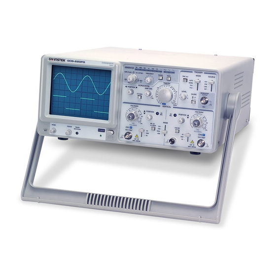
УНИВЕРСАЛЬНЫЙ ДВУХКАНАЛЬНЫЙ GOS-620
(Краткая
инструкция
для пользователя)
ПРЕДУПРЕЖДЕНИЕ
!!! Позиционными
переключателями «MODE»,
«SOURCE»,
«AC,
GND, DC»
пользоваться
с особой осторожностью.
Осциллограф
имеет 4-е группы органов управления,
объединенных по функциональному
назначению и компактно размещенных в
определенных зонах передней панели
осциллографа.
1.
«Включение осциллографа и органы
управление лучом»
(расположены
под экраном)
POWER – Выключатель
сетевого питания,
[Отжат]1
INTER
– Регулятор
яркости изображения,
[В
среднем положении]
FOCUS
– Регулятор
фокуса изображения.
[В
среднем положении]
2.
«Органы
управления каналами вертикального
отклонения»,
графически выделенные под названием
«VERTICAL»
CH 1 – Вход
канала 1
CH 2 – Вход
канала 2
По
каждому каналу:
AC-DC-GND
– Переключатель
входов усилителей:
AC
–
Закрытый
вход,
DC
–
Открытый
вход,
GND
– Вход
усилителя заземлен.
[Включен]
POSITION
– Регулятор
положения лучей по вертикали,
[В
среднем положении]
VOLTS/DIV2
–
Дискретный
переключатель коэффициентов отклонения
(чувствительности).[0,5
В/Дел]
DIV3
– Плавная
регулировка коэффициентов отклонения;
для
установки номинальных коэффициентов
отклонений, указанных на дискретном
переключателе, ручка плавной регулировки
должна быть установлена в крайнее правое
положение при вращении по часовой
стрелке,
PULLx5MAG
– Увеличение
чувствительности в 5 раз.
[Выключен]
Общее
управление каналами:
MODE – переключатель
режимов
работы вертикальных каналов осциллографа:
CH1 – Включен
1-й канал; на экране наблюдается сигнал
только канала 1,
CH2
– Включен
2-й канал; на
экране наблюдается сигнал только канала
2,
DUAL
–
Включены
два канала; на
экране наблюдаются сигналы обоих
каналов,
[Включен]
ADD
– Режим
алгебраического суммирования; на
экране наблюдается сумма или разность
(при нажатой кнопке CH
2 INV –
инверсия сигнала по 2-му каналу) сигналов
1-го и 2го каналов,
CH
2 INV –
Инверсия
сигнала по 2-му каналу
ALT/CHOP
– Переключатель
режимов коммутатора каналов; в
лабораторных работах находится в отжатом
состоянии. (автоматическая подстройка
режимов коммутации).
3.
«Органы
управления разверткой»,
графически выделенные под названием
«HORIZONTAL»
POSITION
– Регулятор
положения лучей по горизонтали.
[В
среднем положении]
TIME/DIV12
– Дискретный
переключатель коэффициентов развертки
(скорости развертки).
[0,5 мc/Дел]
SWP.
VAR
– Плавное
изменение скорости развертки; для
установки номинальных коэффициентов
развертки, указанных на дискретном
переключателе, ручка плавной регулировки
должна быть установлена в крайнее правое
положение «CAL»
при
вращении по часовой стрелке.
x10MAG
– Увеличение
скости развертки в 10 раз.
[Выключен]
4.
«Органы управления синхронизацией»,
графически выделенные под названием
«TRIGGER»
MODE
– Переключатель
режимов запуска развертки:
AUTO
– Автоколебательный
режим работы генератора развертки,
[Включен]
NORM
–
Ждущий режим работы генератора развертки,
TV-V,
TV-H –
Кадровая и строчная развертка ТВ сигнала;
в лаб. работе не используется
SOURCE
–
Переключатель режима синхронизации
(источника синхронизации):
CH1
– Синхронизация
сигналом 1-го канала,
[Включен]
CH2
– Синхронизация
сигналом 2-го канала,
LINE –
Синхронизация
от
питающей сети,
EXT
– Внешняя синхронизация
сигналом, поданным на вход
TRIG IN.
TRIG IN – Вход
для сигналов внешней синхронизации.
LEVEL – Регулятор
уровня синхронизации (уровня сигнала,
при котором срабатывает блок синхронизации).
[В среднем
положении]
SLOPE
–
Переключатель управляющего фронта
сигнала синхронизации:
«
+ » –
синхронизация развертки от положительного
перепада сигнала синхронизации
(положительным фронтом),
«–
» –
синхронизация развертки от отрицательного
перепада сигнала синхронизации
(отрицательным фронтом).
TRIG
IN – Развертка
поочередно синхронизируется сигналами
от 1-го и 2-го каналов. [Отжат]
—
— — — — — — — — — — — — — — — — — —
Режим
работы осциллографа X
– Y
В этом режиме
обеспечивается возможность раздельного
управления внешними сигналами отклонением
луча осциллографа по оси Х и
оси Y; при этом входом оси
Х является вход «CH 1» канала 1, а входом
оси Y является вход «CH 2»
канала 2.
Для
включения такого режима переключатель
TIME/DIV
устанавливается
в положение X – Y . Регулировка
чувствительности по осям Х и Y
осуществляется переключателями
коэффициентов отклонения «VOLTS/DIV»
соответственно по каналу 1 и каналу 2.
Такой режим, в частности, может быть
использован для построения фигур
Лиссажу.
—
— — — — — — — — — — — — — — — — — —
При
включении (POWER)
осциллографа с
рекомендованными выше начальными
установками переключателей на экране
осциллографа должны появиться две (или
одна спаренная) горизонтальные линии.
В случае отсутствия этих линий необходимо
регуляторами
(POSITION)
положения лучей
по
вертикали и
горизонтали
добиться появления этих лучей на экране;
при необходимости увеличить интенсивность
(INTER)
и
изменить фокусировку (FOCUS)
луча.
Полученные
линии следует сфокусировать (FOCUS)
и установить удобную
для наблюдения яркость(INTER);
установить линии вдоль оси Х (жирная
линия сетки); часто бывает полезным
визуально наблюдать начало развертки,
при этом левый край линий должен немного
отступать от левого края экрана.
В
дальнейшем переключатели и регуляторы
осциллографа устанавливаются в
необходимые положения в зависимости
от решаемых задач и в соответствии с
назначениями этих органов управления.
(! не забыть снять с заземления
(GND) переключатели
(AC-DC-GND) входов
усилителей используемых в работе
каналов).
Калибратор
осциллографа выполнен
схемотехнически в виде отдельного
блока, активный выход (CAL)
которого расположен в нижнем левом углу
передней панели (конструктивно выполнен
в виде одного лепестка; «земляной»
провод общий со всей схемой осциллографа).
Выходной сигнал калибратора –
прямоугольные импульсы напряжения
положительной полярности с амплитудой
2В
и частотой 1кГц.
Калибратор
может быть использован для проверки
работоспособности осциллографа. Для
этого поочередно сигнал генератора
подается на входы каналов вертикального
отклонения, используя их входные кабели
(! Обратить внимание, что сигнал подается
через активный, не «земляной» провод;
активным кабелем надо аккуратно коснуться
выходного лепестка генератора). При
установленном режиме каждого канала:
закрытый вход (АС),
коэффициент
отклонения ko
= 0,5
В/Дел, коэффициент развертки kр
= 0,5
мс/Дел, синхронизация от выбранного
канала, на экране должны наблюдаться
прямоугольные импульсы с двойной
амплитудой 4 деления и периодом 2 деления;
обратить внимание при этом на номинальную
(крайнее правое положение) установку
регуляторов (DIV,
SWP. VAR)
плавного изменения соответствующих
коэффициентов. В противном случае
обратиться к преподавателю.
Указания
по спецификации осциллографа.
Коэффициенты
отклонений, коэффициенты развертки и
параметры входов считываются с передней
панели осциллографа.
Дополнительные
сведения:
пределы
основной погрешности: коэффициентов
отклонения kо
= 3%,
коэффициентов
развертки kр
= 3%;
максимальная
нелинейность амплитудной характеристики
каналов н
= 5%,
максимальная
нелинейность развертки р
= 5%;
рабочая
полоса пропускания: для открытого входа
0-10МГц,
для
закрытого входа 10Гц – 10МГц.
1
В квадратных скобках указаы рекомендованные
состояния переключателей перед
включением осциллографа. Остальные
органы управления устанавливаются в
соответствии с решаемой задачей.
2
Вольты/деление, Сек./дел – под делениями
понимаются большие деления (см.) на
экране осциллографа.
3
Органы управления, не отмеченные
полужирным шрифтом, в лабораторных
работах, как правило, не используются.
2
Соседние файлы в папке Описание приборов
- #
- #
- #
Specifications:1918/1918942-gos620fg.pdf file (04 Jan 2023) |
Accompanying Data:
GW Instek GOS-620FG Test Equipment PDF Manual (Updated: Wednesday 4th of January 2023 07:53:18 AM)
Rating: 4.6 (rated by 82 users)
Compatible devices: GDS-800 Series, GOS-6112, GUT-6000A, GPT-9801, PEL-2002, GPT-9500 Series, PEL-2000A Series, C-1200.
Recommended Documentation:
Text Version of Manual
(Ocr-Read Summary of Contents of some pages of the GW Instek GOS-620FG Document (Main Content), UPD: 04 January 2023)
-
24, 5-2.Dual-channel Operation Set the VERT MODE switch to DUAL to display trace in CH2 (The procedure is ‘ same as CHI described in previous section). At this step, the calibrator signal appears in CHI is Square wave, but it appears in CH2 is a straight line as no signal applied to thi…
-
8, 1. PRODUCT INTRODUCTION 1.1 Description The GOS-620FG oscilloscope + Function Generator is a portable-type, dual-channel oscilloscope with function generator. Its bandwidth of DC is up to 20MHz, and its maximum sensitivity is ImVIDIV. The time base provides a maximum sweep time of 0.2uSIDIV.…
-
35, GW Instek GOS-620FG Artisan Technology Group — Quality Instrumentation … Guaranteed | (888) 88-SOURCE | www.artisantg.com
… -
14, 3. PRECAUTIONS BEFORE OPERATION 3.1 Unpacking the instrument The product has been fully inspected and tested before shipping from the factory. Upon receiving the instrument, please unpack and inspect it to check if there is any damages caused during transportation. If any sign of damage is f…
-
28, GW Instek GOS-620FG 5-5.TIMElDIV Control Set the TIMEIDIV switch to display the desired number of cycles of the waveform. If there are too many cycles displayed with good resolution, set to increase the sweep speed. If only a line is displayed, try to slow down the sweep speed. When the sweep speed is faster than the …
-
18, (27)TRIG.ALT Set VERT MODE switch (14) in DUAL or ADD key, select the SOURCE switch (23) by pressing CHI or CH2, then press TRIG.ALT switch(27), the internal triggering source signal will display alternately from CHI and CH2. LINE Display the triggering signal from AC power line frequency signal. EXT …
-
GW Instek GOS-620FG User Manual
-
GW Instek GOS-620FG User Guide
-
GW Instek GOS-620FG PDF Manual
-
GW Instek GOS-620FG Owner’s Manuals
Recommended: Officejet Pro 7500 Series, RF, DHA-S690


-
AEMC instruments PMR-1
n PHASE & MOTOR ROTATION TESTERn PROBADOR DE FASE & ROTACIÓN DE MOTORPMR-1E N G L I S HUser ManualE S PA Ñ O LManual de instrucciones � …
PMR-1 30
-
ETI PI-6000
PRIMARY INJECTION CIRCUIT BREAKER TEST SET INSTRUCTION MANUAL Model PI-6000 Electrical Test Instruments, LLC 8430 Spires Way, Suite A-F Fredrick, MD 21701 www.ETIPrecision.com (410) 857-1880 Fax (410) 857-1387 …
PI-6000 53
-
Zhurui-tec LPT100
ZHURUI-TEC Shenzhen Zhurui Technology Co.,Ltd. 1 / 7 USER MANUAL (LPT100 Lamps Parameters Tester) Packaging list 1. LPT200 lamp parameter tester 1 SET 2. E14 lamp-socket 1 PCS 3. E27 lamp-socket 1 PCS 4. Power Cord …
LPT100 7
-
Macherey-Nagel Visocolor ECO
Water AnalysisMACHEREY-NAGELVISOCOLOR® ECO n Testanleitungen zur visuellen Bestimmung n Test instructions for visual determination n Instructions des tests pour la détermination visuelle n Instrucciones de los tests para la determinación visualMACHEREY-NAGEL GmbH & Co. KG · Neumann-Neander-Str. 6–8 · 52355 …
Visocolor ECO 38
Additional Information:
Operating Impressions, Questions and Answers:

Artisan Technology Group is your source for quality
new and certified-used/pre-owned equipment
• FAST SHIPPING AND
DELIVERY
• TENS OF THOUSANDS OF
IN-STOCK ITEMS
• EQUIPMENT DEMOS
• HUNDREDS OF
MANUFACTURERS
SUPPORTED
• LEASING/MONTHLY
RENTALS
• ITAR CERTIFIED
SECURE ASSET SOLUTIONS
SERVICE CENTER REPAIRS
Experienced engineers and technicians on staff
at our full-service, in-house repair center
WE BUY USED EQUIPMENT
Sell your excess, underutilized, and idle used equipment
We also offer credit for buy-backs and trade-ins
www.artisantg.com/WeBuyEquipment
InstraView REMOTE INSPECTION
LOOKING FOR MORE INFORMATION?
Visit us on the web at www.artisantg.com for more
information on price quotations, drivers, technical
specifications, manuals, and documentation
SM
Remotely inspect equipment before purchasing with
our interactive website at www.instraview.com
Contact us: (888) 88-SOURCE | [email protected] | www.artisantg.com
20MHz Dual Trace Oscilloscope
with Function Generator
MODEL: GOS-620FG
Artisan Technology Group - Quality Instrumentation ... Guaranteed | (888) 88-SOURCE | www.artisantg.com
CONTENTS
PAGE
1. PRODUCT INTRODUCTION ...............................................................................................
1-1 .Description ................................................................................................................
1-2.Feature ......................................................................................................................
2
.
TECHNICAL SPECIFICATION....................................................................
3. PRECAUTIONS BEFORE OPERATION.........................................................
3-1.Unpacking the instrument ...............................................................................................
3-2.Checking the Line Voltage ..............................................................................................
3-3.Environment ...............................................................................................................
3-4.Equipment Installation and Operation ...............................................................................
3-5.CRT Intensity ..............................................................................................................
3-6.Withstanding Voltage of Input Terminals ...........................................................................
4 . PANEL INTRODUCTION ..........................................................................
4.1.Front Panel .................................................................................................................
4-2.Rear Panel ..................................................................................................................
Artisan Technology Group - Quality Instrumentation ... Guaranteed | (888) 88-SOURCE | www.artisantg.com
CONTENTS
PAGE
OPERATION METHOD .............................................................................. 17
S.1.Basic Operation ............................................................................................................ 17
5.2.Dual.channel Operation .................................................................................................19
20
5.3.ADD Operation ............................................................................................................
22
5.4.Triggering ..................................................................................................................
5.S.TIM E I D I V Control.......................................................................................................23
5.6.Sweep Magnification .....................................................................................................23
24
5.7.X.Y Operation ............................................................................................................
5.8.Calibration .................................................................................................................
25
5.9.DC B A L Adjustment ..................................................................................................... 25
5.IO.Function Generator
25
.....................................................................................................
MAINTENANCE..................................................................................... 26
6.1.Fuse Replacement ........................................................................................................
26
26
6.2.Line Voltage ...............................................................................................................
6.3.Cleaning ..................................................................................................................
27
BLOCK DIAGRAM ................................................................................... 28
Artisan Technology Group - Quality Instrumentation ... Guaranteed | (888) 88-SOURCE | www.artisantg.com
SAFETY TERMS AND SYMBOLS
These terms may appear in this manual or on the product:
WARNING. Warning statements identify condition or practices that
could result in injury or loss of life.
CAUTION. Caution statements identify conditions or practices that
could result in damage to this product or other property.
The following symbols may appear in this manual or on the product:
DANGER
ATTENTION
Protective
Frame or chassis
High Voltage
refer to Manual
Conductor
Terminal
Terminal
Artisan Technology Group - Quality Instrumentation ... Guaranteed | (888) 88-SOURCE | www.artisantg.com
FOR UNITED KINGDOM ONLY
NOTE
This leadlappliance must only
be wired by competent persons
WARNING
THIS APPLIANCE MUST BE
EARTHED
IMPORTANT
The wires in this lead are
coloured in accordance with
the following code:
Green1
Yellow: Earth
Blue:
Neutral
Brown: Live(Phase)
As the colours of the wires in main leads may not correspond with the colours
marking identified in your plugiappliance, proceed as follows:
The wire which is coloured Green & Yellow must be connected to the Earth terminal
@
or coloured Green or Green &
marked with the letter E or by the earth symbol
Yellow.
The wire which is coloured Blue must be connected to the terminal which is marked
with the letter N or coloured Blue or Black.
The wire which is coloured Brown must be connected to the terminal marked with the
letter L or P or coloured Brown or Red.
If in doubt, consult the instructions provided with the equipment or contact the supplier.
This cable/appliance should be protected by a suitably rated and approved HBC mains
fuse : refer to the rating information on the equipment andlor user instructions for
details. As a guide, cable of 0.75mmz should be protected by a 3A or 5A hse. Larger
conductors would normally require 13A types, depending on the connection method
used.
Any moulded mains connector that requires removal/replacement must be destroyed
by removal of any h s e & fuse carrier and disposed immediately, as a plug with bared
wires is hazardous if a engaged in live socket. Any re-wiring must be carried out in
accordance with the information detailed on this label.
Artisan Technology Group - Quality Instrumentation ... Guaranteed | (888) 88-SOURCE | www.artisantg.com
EC Declaration of Conformity
We
GOOD WILL INSTRUMENT CO.,LTD.
(1) NO. 95 - I I , Pao Chung Rd., Hsin-Tien City, Taipei Hsien, Taiwan
(2) Plot 522, Lorong Perusahaan Baru 3, Prai Industrial Estate, 13600 Prai, Penang, Malaysia
declare, that the below mentioned product
GOS-620FG
are herewith confirmed to comply with the requirements set out in the Council Directive on the
Approximation of the Law of Member States relating to Electromagnetic Compatibility
(89/336/EEC,92/3 l/E~C,93168/EEC) and Low Voltage Equipment ~irective(73/231E~C).
For the evaluation regarding the Electromagnetic Compatibility and Low Voltage Equipment
Directive, the following standards were applied:
-
EN50081-2: Electromagnetic compatibility
(1993)
Generic emission standard
Part 2: industrial Environment
Conducted Emission
EN 5501 1
class B
Radiated Emiss~on
(1991)
I
Low Voltage Equipment Directive 73/23/EEC
Low Voltage Directive
I
EN 61010-1 : (1993)+A2:(1995)
I
Artisan Technology Group - Quality Instrumentation ... Guaranteed | (888) 88-SOURCE | www.artisantg.com
I
1. PRODUCT INTRODUCTION
1.1 Description
The GOS-620FG oscilloscope + Function Generator is a portable-type, dual-channel oscilloscope with function generator.
Its bandwidth of DC is up to 20MHz, and its maximum sensitivity is ImVIDIV. The time base provides a maximum
sweep time of 0.2uSIDIV. The sweep speed becomes 100nSIDIV after magnifying 10 times. The oscilloscope uses a
6-inch rectangular type cathode-ray tube with red internal graticule. The Function Generator generates triangle wave, sine
wave, and square wave with the frequency range from 0.1 Hz to I MHz.
The product is sturdy, easy to operate and exhibits high operational reliability.
1.2 Features
1) High intensity CRT with high acceleration voltage:
The CRT is a high beam transmission and high intensity type with a high acceleration voltage of 2kV. It displays readable
traces clearly even at high sweep speeds.
2) Wide bandwidth and sensitivity:
In addition to wide bandwidth, DC-20MHz (-3dB), the instrument provides high sensitivity of 5mVIDIV (ImVIDIV at
X 5 MAG). A 20MHz frequency is obtained with improved triggering synchronization.
3) Alternate triggering:
Even with an observation of two different frequency waveforms, each waveform can be triggered stably
4) TV sync triggering:
The oscilloscope has a sync separator circuit for TV-V and TV-H signals triggering.
5) CHI Output:
A signal from 50Q output terminal of CHI located on rear panel can be applied to frequency counteror other instruments.
Artisan Technology Group - Quality Instrumentation ... Guaranteed | (888) 88-SOURCE | www.artisantg.com
6 ) Z-Axis Input:
Intensity modulation capability permits time or frequency markers to be added. Trace blank with positive signal, TTL
compatible.
7) X-Y operation:
Set the switch to X-Y to operate the instrument as an X-Y oscilloscope. CHI can be applied as a horizontal deflection (X-axis)
while CH2 provides vertical deflection (Y-axis).
8) Built-in Function Generator with BNC output of 50 '2.
9) Three kinds of waveforms are available with 50R output.
10)Waveform frequency is up to I MHz.
Artisan Technology Group - Quality Instrumentation ... Guaranteed | (888) 88-SOURCE | www.artisantg.com
GOS-620FG 20MHz OSCILLOSCOPE + FUNCTION GENERATOR
PECIFICATIONS
,OSCILLOSCOPE
- -
'ERTICAL
AXIS
-
lsensitivitv
1 5 m ~ 5VIDIV. 10 stem in 1-2-5 seauence
Sensitivity Accuracy
53% ( x 5 MAG : 55%).
Vernier Vertical sensitivity To 112.5 or less of panel-indicated value.
DC-20MHz ( x 5MAG: DC-7MHz).
Frequency bandwidth
AC coupling: Low limit frequency of 10Hz.
(With reference to IOOkHz, 8DIV. Frequency response at -3dB).
Approx. 17.5nS (x5 MAG: Approx. 50nS).
Rise time
Approx. 1M ohm 11 Approx. 25pF.
Input impedance
Square Wave
Overshoot : 5 5% ( At IOmVIDIV range).
Characteristics
Other distortions and other ranges: 5% added to the above value.
DC Balance Shift
Panel adjustable.
< i O . l D I V of amplitude change when waveform of 2 DIV at graticule center is moved vertically.
Linearity
CHI : CHI single channel.
CH2 : CH2 single channel.
Vertical modes
DUAL : CHI and CH2 are displayed. ALT or CHOP selectable at any sweep rate.
ADD : CHI + CH2 algebraic addition.
~
~
-
Frequency
Input Coupling
Maximum Input Voltage
common Mode
Ratio
Isolation between channels
(At 5mVIDIV range)
CHI signal output
CH2 TNV BAL.
-
~
Approx, 2jOkHHz,
AC, GND, DC.
300Vpeak
(AC:
frequency I kHz or lower).
.
.
Set probe switch at 1: 1, the maximum effective readout is 4 W p p (14Vrms at Sine wave).
set probe switch at 10: 1, the maximum effective readout is 400Vpp(140Vrms at Sine wave).
50:l br better at 5 6 w z sinusoidal wave. (When sensitivities of CHI and CH2 are set equally).
>1000: 1 at 50kHz.
>30: 1
at 20MHz.
At least 20 mvldiv into a 50Rterminal. Bandwidth is 50Hz to 5MHz at least.
Balanced point variation: 51 DIV (Reference at center graticule).
- 3 Artisan Technology Group - Quality Instrumentation ... Guaranteed | (888) 88-SOURCE | www.artisantg.com
GOS-620FG 20MHz OSCILLOSOPE + FUNCTION GENERATOR
'ECIFICATIONS
I
/Triggering source
Coupling
Slope
J~ensitivity
'RIGGERING Triggering modes
EXT Triggering Signal Input
Input Impedance
Max. Input Voltage
Sweep Time
Sweep Time Accuracy
Vernier Sweep Time Control
IORIZIONAL Sweep Magnification
xlOMAG Sweep Time
AXIS
Accuracv
Linearity
Position shift caused by
I
ITV
Approx.: 1M ohm I/ approx. 25Pf.
300V (DC+AC peak), AC: Frequency not higher than I kHz.
0.5 Sec/DIV, 20 steps in 1-2-5 sequence.
0 . 2 , ~Sec
1-3%.
_<1/2.5of panel-indicated value.
10 times (maximum sweep time 100nSec/DIV).
-
4 59'0, (20nSec- 5OnSec are uncalibrated).
?3%, xlOMAG:+5% (20ns and 50ns are uncalibrated).
- - -- - --
Within 2 div, at CRT screen center.
Sensitivity
Frequency Bandwidth
Same as vertical axis (X-axis:CHl input signal; Y-axis:CH2 input signal.).
DC to at least 500kHz.
at DC -50kHz.
x
. 1 OMAG
.
LY MODE
CHI, CH2, LINE, EXT (CHI and CH2 can be selected only in the DUAL or ADD vertical mode).
In ALT mode, if the TRIG. ALT switch is pushed in, it can alternate triggering of two different
source.
IAC: 20Hz to full bandwidth.
I+ I -.
1 2 0 -~ ~2MHz : 0.5 DIV, TRIG-ALT:2 DIV, EXT : 200mV.
12 -- 20MHz
: 1.5 DIV, TRIG-ALT:3 DIV, EXT : 8OOrnV.
: Sync pulse more than 1 DIV (EXT: 1V).
AUTO : Sweeps run in the free mode when no triggering input signal is applied.
(Applicable for repetitive signals of frequency 25Hz or over.).
NORM : When no triggering signal is applied, the trace is in the ready state, but not displayed.
TV-V
: This setting is used when observing the entire vertical picture of television signal.
TV-H
: This setting is used when observing the entire horizontal picture of television signal.
(Both TV-V and TV-H synchronize only when the synchronizing signal is negative )
Ix-Y
Phase Difference
ID'
Artisan Technology Group - Quality Instrumentation ... Guaranteed | (888) 88-SOURCE | www.artisantg.com
-
SPECIFICATION
/sensitivity
l ~ r e ~ u e n cBandwidth
y
Input resistance
Z AXIS
Maximum lnput Voltage
Waveform
Frequency
CALIBRATION
Duty Ratio
VOLTAGE
Output Voltage
Output Impedance
Type
Phosphor
Acceleration Voltage
CRT
Effective Screen Size
Graticule
Trace Rotation
2.FUNCTION GENERATOR
Output Function Range
Output Waveform
IFreauencv Variable Range
Output Voltage
GOS-620FG 20MHz
5 Vp-p (Positive-going signal decreases intensity).
DC
2MHz.
Approx. 4 7 K R .
30V (DC+AC peak, AC frequency51 kHz).
Positive-going Square wave.
Approx. 1 kHz.
Within 48:52.
2 Vp-p
. . i2%.
Approx. I k R
6-inch rectangular type. internal graticule.
P 31.
Approx. 2kV.
8 x 10 DIV (I DIV = lOmm (0.39in)).
Internal.
Provided.
-
10 1 Hz - 1 MHz (7 steps)
l ~ i n Wave.
e
Square Wave and Triangle Wabe
110:1 or more.
5 0 R i 10%.
W
c
u
i
t
) continuous conversion.
DC offset possible over 10V when opened.
-
Square wave Unsymmetry
Souare wave RiselFall Time
OSCILLOSCOPE + FUNCTION GENERATOR
*
1% MaxiloHz 20kHz)
( t 3 % or less ( ~ nI kHz maximum)
150R outuut 1 2 0 n ~or less
Artisan Technology Group - Quality Instrumentation ... Guaranteed | (888) 88-SOURCE | www.artisantg.com
I
GOS-620FG 20MHz OSCILLOSCOPE + FUNCTION GENERATOR
SPECIFICATION
3.GENERAL
Power Source
Power Consumption
Operation Environment
Storage Temperature & Humidity
Accessories
4C115V, 230V k 15% selectable, 50Hz or 6OHz.
4pprox. 45VA, 40W(max.)
Indoor use
Altitude up to 2000 m
Ambient temperature :
To satisfy specifications : 10" to 35°C (50' to 95" F)
Maximum operating ranges: 0" to 40°C(32 'to 104" F)
Relative humidity: 85% RH(max.) non condensing
Installation Category I1
Pollution degree 2
- 10" to 70°C. 70%RH(maximum).
'ower cord
X l
nstruction manual
X l
'robes
X 2
Dimensions
Weight
Artisan Technology Group - Quality Instrumentation ... Guaranteed | (888) 88-SOURCE | www.artisantg.com
3. PRECAUTIONS BEFORE OPERATION
3.1 Unpacking the instrument
The product has been fully inspected and tested before shipping from the factory. Upon receiving the instrument, please
unpack and inspect it to check if there is any damages caused during transportation. If any sign of damage is found, notify
the bearer andor the dealer immediately.
3.2 Checking the Line Voltage
The product can be applied any kind of the line voltage shown in the table below. Before connecting the power plug to an
AC line outlet, make sure the voltage selector of the rear panel is set to the correct position corresponding to the line voltage.
It might be damaged the instrument if connected to the wrong AC line voltage.
A
/ !
WARNING. To avoid electrical shock, the power cord protective grounding conductor must be
connected to ground.
The fuse must be changed following after the line voltage shown as below:
T 0.63A
AC 1 15V
97-1 32V
AC 230V
195-250V
A
T 0.3 15A
WARNING. To avoid personal injury, disconnect the power cord before removing the fuse holder.
Artisan Technology Group - Quality Instrumentation ... Guaranteed | (888) 88-SOURCE | www.artisantg.com
0
CNSURE THE POWER IS REMOVED FROM
IHE INSTRUMENT BEFORE REPMCING THE FUSE
POWER MAX 40 WAIlS, 45VA
IEClDlO 25W CAT
I1
I
I
Artisan Technology Group - Quality Instrumentation ... Guaranteed | (888) 88-SOURCE | www.artisantg.com
4-1.Front Panel
CRT :
(6) POWER
Main power switch of the instrument. Turn on the switch to light the LED (5).
(2).INTEN
Control the brightness of the spot or trace.
(3) FOCUS
Focus the trace to the sharpest image.
(4) TRACE ROTATION
Semi-fix potentiometer for aligning the horizontal trace in parallel with graticule lines.
(33)FILTER
The filter is easy for waveform viewing.
Vertical Axis:
(8) CH 1 (X) input
The vertical input terminal of CH 1 is X-axis in X-Y operation,
(20)CH 2 (Y) input
The vertical input terminal of CH2 is Y-axis in X-Y operation,
(1 0) &(I 8)AC-GND-DC
Select connection mode between input signal and vertical amplifier.
AC
AC coupling
GND Vertical amplifier input is grounded and input terminals are disconnected.
DC
DC coupling
(7) & (22)VOLTSlDIV
Select the vertical axis sensitivity from SmVIDIV to SVJDIV with 10 ranges totally.
Artisan Technology Group - Quality Instrumentation ... Guaranteed | (888) 88-SOURCE | www.artisantg.com
(9) & (2 1)VARIABLE
Fine adjustment of sensitivity with a factor of 2112.5 of the indicated value. The sensitivity is calibrated to specific
value in the CAL position. When this knob is pulled out (x5 MAG state), it will multiply 5 by the amplifier sensitivity.
(13) & (17)CHl & CH2 DC BAL.
The knobs are used for adjusting the attenuator balance. See page 20 DC BAL adjustments for details.
(I I)&(] 9) * 'POSITION
Vertical positioning control of trace or spot.
(I4)VERT MODE Select operation modes of CH 1 and CH 2 amplifiers.
Operate the oscilloscope as a single-channel instrument by selecting CHI alone.
CH I
Operate the oscilloscope as a single-channel instrument by selecting CH2 alone.
CH 2
Operate the oscilloscope as a dual-channel instrument by selecting CHI and CH2.
DUAL
The oscilloscope displays the algebraic sum (CHI + CH2) or subtraction (CHI - CH2) of the two signals
ADD
(the subtraction function effects only when push in CH2 INV(16) button).
(12)ALTICHOP
When this switch is released in the dual-trace mode, the CHI and CH2 inputs are alternately displayed (normally used at
faster sweep speeds).
When this switch is depressed in the dual-trace mode, the CHI and CH2 inputs are chopped and displayed
simultaneously. (normally used at slower sweep speeds).
(16)CH2 INV
When press CH2 M V button, it will inverts the CH2 input signal in CH2 and in ADD MODE, the CH2 trigger signal
pickoff is also inverted.
(23)SOURCE
Select the internal triggering source signal, and the EXT TRIG IN input signal.
CH 1 Press key DUAL or ADD of VERT MODE (14), select CHI to get internal triggering source signal
CH 2 Press key DUAL or ADD of VERT MODE (14), select CH2 to get internal triggering source signal
Artisan Technology Group - Quality Instrumentation ... Guaranteed | (888) 88-SOURCE | www.artisantg.com
(27)TRIG.ALT
Set VERT MODE switch (14) in DUAL or ADD key, select the SOURCE switch (23) by pressing CHI or CH2, then
press TRIG.ALT switch(27), the internal triggering source signal will display alternately from CHI and CH2.
Display the triggering signal from AC power line frequency signal.
LINE
Obtain the external triggering source signal by applying external signal to EXT TRIG IN input terminal (24).
EXT
(26)SLOPE
Triggering slope button.
"+"
Triggering occurs when the trigger signal crosses the trigger level by positive-going course.
Triggering occurs when the trigger signal crosses the trigger level by negative-going course
(28)LEVEL
Display a synchronized stationary waveform and set a start point for the waveform.
Toward "+" The trigger level moves upward on the display waveform.
Toward "-" The trigger level moves downward on the display waveform.
(25)TRIGGER MODE
Trigger mode selection.
If no trigger signal applied or the trigger signal frequency is less than 25Hz, the sweep will be in the free run
AUTO
mode.
NORM If no trigger signal applied and sweep is in a stand-by state, there will be no trace appear.
TV-V
Used for observing entire vertical picture of television signal.
TV-H
Used for observing entire horizontal picture of television signal.
(Both TV-V and TV-H synchronize only when the synchronizing signal is negative.)
'6-
*7
Time Base:
(29)TIME/DIV
Provide sweep time ranges @om0.2 uS/div to 0.5 Sldiv with 20 steps totally.
X-Y
Use the instrument as an X-Y oscilloscope by setting to X-Y position.
Artisan Technology Group - Quality Instrumentation ... Guaranteed | (888) 88-SOURCE | www.artisantg.com
(30)s WP.VAR
Vernier control knob of the sweep time used when CAL and the sweep time is calibrated to the vh!ue preset in
TIMEDIV. The sweep of TIMEBIV can be varied continuously when shaft is not in CAL position. Rotate the control
knob to CAL position and the sweep time is calibrated to the preset value of the TIMEDIV. Counterclockwise rotate the
control knob to the bottom to delay the sweep by 2.5 time or more.
(32)
POSITION
Adjust the trace or spot in horizontal position.
(31)X 10 MAG
Magnify 10 by pressing this key.
Function Generator:
(39)GENERATOR OUTPUT
The main output terminal with 50 R output impedance.
(40) WAVEFORM SELECTOR
The waveform change following after each button pushing in Sine wave, Triangle wave, and Square wave sequence.
(4 1)OUTPUT WAVEFORM DISPLAY
Display the current output waveform.
(42)FREQ RANGE Switch:
The frequency range changes following after each button pushing in lM, look, 10k, 1k, 100, 10, and 1 sequence.
(43)FREQUENCY RANGE DISPLAY
Display the current frequency range.
Artisan Technology Group - Quality Instrumentation ... Guaranteed | (888) 88-SOURCE | www.artisantg.com
(44)FREQUENCY Knob
Rotate the knob clockwise to get higher frequency and reverse the rotation of knob to get lower frequency.
(45)AMPLITUDEIDC LEVEL Adjustment Knob
Rotate outside knob clockwise to get higher amplitude and reverse the rotation of knob to get lower amplitude. The
inside knob is for DC Level adjustment, it works only when the knob being pulled up. Pull up the knob and rotate it
clockwise to get positive DC Level, and reverse the rotation of knob to get negative DC Level.
Others:
(1) CAL
This terminal delivers the calibration voltage of 2 Vp-p, I kHz, positive square wave.
(1 5)GND
Ground terminal of oscilloscope mainframe.
4-2.Rear Panel
Triggering:
(24)EXT TRlG IN Input Terminal
lnput Terminal is used for external triggering signal by setting SOURCE switch (23) to the EXT position.
(34)Z AXIS INPUT
Input terminal for external intensity modulation signal.
(35)CH 1 SIGNAL OUTPUT
Delivers a voltage of approximately 20mVIDIV from the CHI signal to 50 R terminal for frequency counting.
Artisan Technology Group - Quality Instrumentation ... Guaranteed | (888) 88-SOURCE | www.artisantg.com
AC POWER Input Circuit:
(36)AC Power input connector
Connect the AC power cord (supplied) to this connector.
(37)FUSE & line voltage selector
Fuse rating is shown in Page 7 Line voltage selector to select power sources.
(3 8)Studs
Studs is not only used as a stand for laying the oscilloscope on its back to operate it in the upward posture, also used for
winding up the power cord.
Artisan Technology Group - Quality Instrumentation ... Guaranteed | (888) 88-SOURCE | www.artisantg.com
5.0PERATION METHOD
5-1.Basic Operation---Single-channel Operation
Before connecting the power cord to an AC line outlet, make sure that the AC line voltage input switch on the rear panel of
the instrument is correctly set for the AC line voltage. After ensuring the voltage setting, set the switches and controls of the
instrument as shown below:
Item
No
POWER
INTEN
FOCUS
VERT MODE
ALTICHOP
CH 2 INV
A
POSITION
VOLTS/DIV
VARIABLE
AC-GND-DC
SOURCE
(6)
(2)
(3)
(14)
(12)
(16)
(1 1)(19)
(7)(22)
(9)(21)
(10)(18)
(23)
Setting
Disengage position(0FF)
Mid-position
Mid-position
CH 1
Released(ALT)
Released
Mid-position
0.5V/DIV
CAL(c1ockwise position)
GND
CHI
Item
SLOPE
TRIG. ALT
TRIGGER MODE
TIME/DIV
SWP.VER
POSITION
'
I
No
k26)
(27j
(25)
(29)
(30)
(32)
+
Setting
Released
AUTO
O.SmSec/DIV
CAL position
Mid-position
Released
Artisan Technology Group - Quality Instrumentation ... Guaranteed | (888) 88-SOURCE | www.artisantg.com
After setting the switches and control knobs as mentioned, connect the power cord to the AC line outlet, then follow the
procedure describes as follows:
1)
Press the POWER switch and make sure that the power LED is turned on. In about 20 seconds, a trace will appear on
the CRT screen. If no trace appears in about 60 seconds, counter check the switch and control setting.
2) Adjust the trace to an appropriate brightness and image with INTEN and FOCUS control knob respectively.
3) Align the trace with the horizontal central line of the graticule by adjusting the CH1 POSITION control knob and
TRACE ROTATION control knob(adjusted with screwdriver).
4) Connect the probe to the CHI INPUT terminal and apply 2Vp-p CALIBRATOR signal to the probe tip.
5)
Set the AC-GND-DC switch to AC, a waveform will be displayed on the CRT 0
screen as shown in the figure 5-1.
FIG. 5-1
6) Adjust the FOCUS control knob to trace image sharply
7) Display the signal waveform clearly by adjusting the VOLTSIDIV switch and
TIMEIDIV switch to appropriate position.
'
POSITION control knobs to appropriate
8) Adjust the ' POSITION and
position to align the waveform with the graticule, so that voltage (Vp-p) and
period (T) can be read conveniently.
The descriptions above are the basic operating procedures for CH 1 single-channel operation of oscilloscope. So is CH2 singlechannel operation. For further operation methods will be explained in the subsequent paragraph.
Artisan Technology Group - Quality Instrumentation ... Guaranteed | (888) 88-SOURCE | www.artisantg.com
5-2.Dual-channel Operation
Set the VERT MODE switch to DUAL to display trace in CH2 (The procedure is
same as CHI described in previous section). At this step, the calibrator signal
appears in CHI is Square wave, but it appears in CH2 is a straight line as no
signal applied to this channel yet.
'
Fig. 5-2
Now, apply the calibrator signal to the vertical input terminal of CH2 through the
probe with the same procedure as for CHI. Set the AC-GND-DC switch to AC,
and adjust vertical POSITION knobs (I 1) and (l9), the signals will be displayed
on both channels as shown in Figure 5-2.
S
i of CHI
Signal of CW
When ALTICHOP switch is released (ALT MODE), the input signals which applied respectively to CHland CH2 appears on
the screen alternately at each sweep. This setting is used when the sweep time is short in 2-channel observation.
When ALTICHOP switch is pressed (CHOP MODE), the input signals which applied to CH land CH2 are chopped and display
on the screen at the same time with the frequency of 250kHz. This setting is used for low speed sweep.
Set to dual channel operation (DUAL or ADD mode), select CHI or CH2 signal from SOURCE switch to get triggering source
signal. If both CHI and CH2 signals are in a synchronized relation, both waveforms will be displayed in stationary states. If not,
only a signal stationary waveform will be appeared. If press TRIG. ALT push button, both waveforms can also be displayed in
stationary states.
Artisan Technology Group - Quality Instrumentation ... Guaranteed | (888) 88-SOURCE | www.artisantg.com
5-3 ADD Operation
An algebraic sum of the CHI and CH2 signals can be displayed on the screen by setting the VERT MODE switch to ADD.
POSITION knob
The displayed signal will be difference between CHI and CH2 if press CH2 INV push button. Adjust A
of CH1 or CH2 can make vertical position, to the advantage of the linearity of the vertical amplifiers, it's better to set
A
POSITION knob of both channels in middle position.
5-4.Triggering
Proper triggering is essential for an efficient operation of the instrument. Users must make themselves familiar with the
triggering functions and procedures thoroughly:
(1)Functions of MODE switch:
AUTO
Select automatic sweep operation by setting to AUTO mode, the sweep generator will freely generate a sweep
without a trigger signal. However, it will automatically switch to triggering sweep operation if an acceptable
trigger source signal is preset. The AUTO mode is handy for observing the waveform when first set up the
instrument, as it provides sweep function for waveform observation until properly set to other mode. Once
starting to set the control mode, the operation often jumps back to the NORM trigger mode as it is much more
sensitive. Automatic sweep must be used for DC measurements and signals with low amplitude in order not to
trigger the sweep.
NORM
The NORM mode provides normal triggering sweep operation. The sweep will not act until the selected trigger
source signal crosses the threshold level set by TRIG LEVEL control knob. The triggering generate one sweep
which will come to inactivate until another triggering occurs. In the NORM mode, there will be no trace unless
an adequate trigger signal is present. In the ALT mode of dual trace operation with NORM sweep selected,
there will be no trace unless both CHI and CH2 signals are adequate for triggering.
TV-V
Set the MODE switch to TV-V mode, select vertical sync pulses for sweep triggering to view composite video
waveforms. Select vertical sync pulses as a triggering to view vertical fields and frames of video. A sweep time
of 2 msi'div is appropriate for viewing fields of video and 5 ms/div for complete frames (two interlaced fields)
of video.
Artisan Technology Group - Quality Instrumentation ... Guaranteed | (888) 88-SOURCE | www.artisantg.com
TV-H
Set the MODE switch to TV-H mode and select horizontal sync pulses for sweep triggering to view composite
video waveforms. Select horizontal sync pulses as a triggering to view horizontal lines of video. A sweep time
of about 10 usldiv is appropriate for displaying lines of video. Display the exact number of desired waveforms
by setting SWP VAR control knob.
This oscilloscope synchronizes with only (-) polarity, that is, the sync pulses are negative and the video is
positive as shown in Fig. 5-3.
Fig. 5-3
(2)Functions of SOURCE switch:
Apply the displayed signal itself or a trigger signal, which has a time relationship with the displayed signal, to the trigger
circuit to display a stationary signal on the CRT screen. The SOURCE switch is used for selecting these trigger sources.
CHI
CH2
The internal trigger source is used most commonly.
The signal applied to the vertical input terminal is branched off away from the preamplifier and is fed to the
trigger circuit through the VERT MODE switch. Since the trigger signal is the measured signal itself, a stable
waveform can be readily displayed on the CRT screen. When in the DUAL or ADD operation, the selected
signal through the SOURCE switch is used as a trigger source signal.
LINE
The AC power line frequency signal is used as a trigger signal. This method is effective when the measured
signal has a relationship with the AC line frequency, especially for measurements of low level AC noise of
audio equipment, thyristor circuits, etc.
EXT
The sweep is triggered by an external signal applied to the external trigger input tenninal. An external signal
which has a periodic relationship with the measured signal is used. Because the measured signal is not used as
the triggering signal, the waveforms can be displayed more independent than the measured signal.
Artisan Technology Group - Quality Instrumentation ... Guaranteed | (888) 88-SOURCE | www.artisantg.com
(3)Functions of TRIG LEVEL control knob and SLOPE button:
A sweep triggering is developed when the trigger source signal crosses a preset threshold level. Rotate TRIG LEVEL control
knob to vary the threshold level. In the "+" direction, the trigger threshold shifts to a more positive value, and in the "" direction, the trigger threshold shifts to a more negative value. When set the control knob in the center, the threshold level will
be on the average of the signal used as the trigger source.
Adjust TRIG LEVEL control knob for the desired start point of sweep on a waveform. On sine wave signals, the phase at which
sweep begins is variable. Note that if rotate TRIG LEVEL control knob toward its extreme "+" or "-", no sweep will be
developed in the NORM trigger mode because the trigger threshold exceeds the peak amplitude of the sync signal.
When set TRIG SLOPE button to the (+) position (up), the sweep is developed form the trigger source waveform as it crosses
the threshold level in a positive-going direction. When set TRIG SLOPE button to the (-) position (down), a sweep triggering is
developed fiom the trigger source waveform as it crosses the threshold level in a negative-going direction. The slope (polarity)
trigger signal as shown in Figure 5-4.
Fig. 5-4
(4) Function of TRIG ALT button:
The TRIG ALT button is used to select alternate triggering and display the selected DUAL-trace of VERT MODE (the switch
control knob CHI. CH2, DUAL and ADD modes). In the alternate trigger mode (when select dual-trace operation), the trigger
source alternates between CHI and CH2 with each sweep. This is convenient for checking amplitudes, wave-shape, or
waveform period measurements, and even permits simultaneously observing two waveforms which are not related to frequency
or period. However, this setting is not suitable for phase or timing comparison measurements. For such measurements, both
traces must be triggered by the same sync signal.
If press both CHOP and TRIG ALT buttons during dual-trace operation, synchronization of the display is not possible because
the chopping signal will be triggered. Use ALT mode itself, or select CH1 or CH2 as trigger source.
Artisan Technology Group - Quality Instrumentation ... Guaranteed | (888) 88-SOURCE | www.artisantg.com
5-5.TIMElDIV Control
Set the TIMEIDIV switch to display the desired number of cycles of the waveform. If there are too many cycles displayed
with good resolution, set to increase the sweep speed. If only a line is displayed, try to slow down the sweep speed. When
the sweep speed is faster than the observed waveform, only pan of it will be displayed, which may appear as a straight line
for a Square wave or Pulse waveform.
5-6.Sweep Magnification
When a certain part of displayed waveform is needed to be
expanded timewise, a faster sweep speed may be used.
However, if the required portion is apart from the starting
point of the sweep, it may run off the CRT screen. In this
case, push the xlOMAG button to expand 10 times the
displayed waveform from the right to the left in the center
of screen. The sweep time with the magnification operation
is as follows:
(Value indicated by TIMEIDIV switch) x 1/10
Thus, the unmagnified maximum sweep speed (I nSec/DIV)
can be increased with the magnification as follows :
1 pSecIDIV x 1/10 = 100nSec/DIV
FIG. 5-5
Any part can be covered by
means of POSITION control
Artisan Technology Group - Quality Instrumentation ... Guaranteed | (888) 88-SOURCE | www.artisantg.com
5-7.X-Y Operation
FIG. 5-6
Set the TIMEIDIV switch to X-Y position to operate the
instrument as an X-Y oscilloscope. Each input is applied to the
instrument as follows
X-axis signal (horizontal axis signal ) : CHI INPUT.
Y-axis signal (vertical axis signal) : CH2 INPUT.
Note:
When high frequency signals are displayed in X-Y operation,
pay attention to the frequency bandwidth and phase
difference between X and Y-axis.
Y axis (CH2)
X ~Xiy
(CHI)
I i I I I I
The X-Y operation permits the oscilloscope to perform many state-of-the-art measurements which the conventional sweep
operation could not make. The CRT display becomes an electronic graph of two instantaneous voltages. The display may be a
direct comparison of the two voltages such as a vectorscope display of video color bar patterns. However, the X-Y mode can
almost be used in graph of any dynamic characteristic if a transducer is adopted to change the characteristic (frequency,
temperature, velocity, etc.) of voltage. One common application is frequency response measurements that the Y-axis
corresponds to signal amplitude and the X-axis corresponds to frequency.
1. Set the TIMEIDIV control knob to the X-Y position (fdly counterclockwise), CHI becomes the X-axis input and CH2
becomes the Y-axis input.
POSITION control knobs respectively.
POSITION and CH2 A
2. Adjust X and Y positions by using the horizontal
3 . Adjust the amount of vertical (Y-axis) deflection by using CH2 VOLTSIDIV and VAR control knobs.
4. Adjust the amount of horizontal (X-axis) deflection by using CH 1 VOLTSIDIV and VAR control knobs.
'
Artisan Technology Group - Quality Instrumentation ... Guaranteed | (888) 88-SOURCE | www.artisantg.com
5-8.Calibration of Probe
As explained previously, the probe makes up a wide range attenuator. Unless phase compensation is properly done, the
displayed waveform will be distortion causing measurement errors. Therefore, the probe must be properly compensated before
use. Connect 10:l probe BNC to the INPUT terminal of CHI or CH2 and set VOLTSIDIV switch at 50mV. Connect the
probe tip to the calibration voltage output terminal and adjust the compensation trimmer on probe for optimum Square wave
(minimum overshoot, rounding off and tilt).
FIG. 5-7
(a) Correct compensation
(b) Over compensation
(c) Insufficient compensation
5-9.DC BAL Adjustments
The ATT balance of the vertical axis can be adjusted easily.
(1)Set the input coupling switches of CHI and CH2 to GND and set the TRIG MODE to AUTO, then position the base line
to the center.
(2)Adjust the VLOTSmIV switch to 5mV-1 OrnV and fix the line does not move.
5-1O.Function Generator
The instrument also provides the basic features of Function Generator to satisfy general demand with simply and intuitional
operation method by adjusting the control knobs directly fiom front panel for output waveform, amplitude, DC level and etc.
All the control knobs located in front panel are marked with the same color to prevent missetting.
Artisan Technology Group - Quality Instrumentation ... Guaranteed | (888) 88-SOURCE | www.artisantg.com
The following instructions are executed by qualified personnel only. To avoid electrical shock, do not perform any servicing
other than the operating instructions unless you are qualified to do so.
6-1.Fuse Replacement
If the fuse blows, the power lamp indicators will not light and the instrument will not start. The fuse holder should not
normally be opened unless a problem has been caused to the unit. Try to determine and correct the cause of the blown fuse and
replace with a fuse of correct rating and type (see page 7 ) on the rear panel (see fig. 4-2).
WARNING. For continued fire protection. Replace fuse only with 250V fuse of the specified type and rating,
and disconnect power cord before replacing fuse.
6-2 Line Voltage Conversion
The primary winding of the power transformer is tapped to permit operation from 115V, or 230VAC 50160Hz line voltage.
Conversion from one line voltage to another is done by changing the line voltage selector switch as shown in Fig. 4-2. The rear
panel identifies the line voltage to which the unit was factory set. To convert to a different line voltage, perform the following
procedure:
(1)Make sure the power cord is unplugged.
(2)Adjust the line voltage selector switch to the desired line voltage position.
(3)A change in line voltage may also require a corresponding change of fuse value. Install the correct fuse value as listed on
rear panel.
Artisan Technology Group - Quality Instrumentation ... Guaranteed | (888) 88-SOURCE | www.artisantg.com
6-3 Cleaning
To clean the instrument, use a soft cloth dampened in a solution of mild detergent and water. Do not spray cleaner directly
onto the unit because it may leak into the cabinet and cause damage. Do not use chemicals containing benzine, benzene,
toluene, xylene, acetone, or similar solvents. Do not use abrasive cleaners on any portion of the oscilloscope.
Artisan Technology Group - Quality Instrumentation ... Guaranteed | (888) 88-SOURCE | www.artisantg.com
7.BLOCK DIAGRAM
CH1 (X)
PRWP
X-AXIS S I W
L
TRIG
INP(ITANP
CH2
EXT TRIG
WRIT
EXT
-
TRIG
GENERATOR
1
Am0
C1RCUi-l
(A) SWEEP
GENERATOR
FREE R W
SIWL
+
HORUCUTAL
MCHIffi
HORUOMAL
OUTPUT AMP
AC LINE
?LET --POWER
SUPPLY
SOWRE-WAVE
CALIBRATOR
Artisan Technology Group - Quality Instrumentation ... Guaranteed | (888) 88-SOURCE | www.artisantg.com
SWBO V z
Artisan Technology Group - Quality Instrumentation ... Guaranteed | (888) 88-SOURCE | www.artisantg.com
Artisan Technology Group - Quality Instrumentation ... Guaranteed | (888) 88-SOURCE | www.artisantg.com
Artisan Technology Group is your source for quality
new and certified-used/pre-owned equipment
• FAST SHIPPING AND
DELIVERY
• TENS OF THOUSANDS OF
IN-STOCK ITEMS
• EQUIPMENT DEMOS
• HUNDREDS OF
MANUFACTURERS
SUPPORTED
• LEASING/MONTHLY
RENTALS
• ITAR CERTIFIED
SECURE ASSET SOLUTIONS
SERVICE CENTER REPAIRS
Experienced engineers and technicians on staff
at our full-service, in-house repair center
WE BUY USED EQUIPMENT
Sell your excess, underutilized, and idle used equipment
We also offer credit for buy-backs and trade-ins
www.artisantg.com/WeBuyEquipment
InstraView REMOTE INSPECTION
LOOKING FOR MORE INFORMATION?
Visit us on the web at www.artisantg.com for more
information on price quotations, drivers, technical
specifications, manuals, and documentation
SM
Remotely inspect equipment before purchasing with
our interactive website at www.instraview.com
Contact us: (888) 88-SOURCE | [email protected] | www.artisantg.com
Table of Contents for GW Instek GOS-620FG:
-
1. PRODUCT INTRODUCTION 1.1 Description The GOS-620FG oscilloscope + Function Generator is a portable-type, dual-channel oscilloscope with function generator. Its bandwidth of DC is up to 20MHz, and its maximum sensitivity is ImVIDIV. The time base provides a maximum sweep time of 0.2uSIDIV. The sweep speed becomes 100nSIDIV after magnifying 10 times. The oscilloscope uses a 6-inch rectangular type cathode-ray tube with red internal graticule. The Function Generator generates triangle
-
AC POWER Input Circuit: (36)AC Power input connector Connect the AC power cord (supplied) to this connector. (37)FUSE & line voltage selector Fuse rating is shown in Page 7 Line voltage selector to select power sources. (3 8)Studs Studs is not only used as a stand for laying the oscilloscope on its back to operate it in the upward posture, also used for winding up the power cord. Artisan Technology Group — Quality Instrumentation … Guaranteed | (888) 88-SOURCE | www.artisantg.com
-
CONTENTS PAGE OPERATION METHOD …………………………………………………………………… 17 S.1.Basic Operation ……………………………………………………………………………………………… 17 ……………………………………………………………………………………. 5.2.Dual.channel Operation 19 5.3.ADD Operation …………………………..
-
5.0PERATION METHOD 5-1.Basic Operation—Single-channel Operation Before connecting the power cord to an AC line outlet, make sure that the AC line voltage input switch on the rear panel of the instrument is correctly set for the AC line voltage. After ensuring the voltage setting, set the switches and controls of the instrument as shown below: Setting Disengage position(0FF) Mid-position Mid-position CH
-
5-2.Dual-channel Operation Set the VERT MODE switch to DUAL to display trace in CH2 (The procedure is ‘ same as CHI described in previous section). At this step, the calibrator signal appears in CHI is Square wave, but it appears in CH2 is a straight line as no signal applied to this channel yet. Now, apply the calibrator signal to the vertical input terminal of CH2 through the probe with the same procedure as
-
(9) & (2 1)VARIABLE Fine adjustment of sensitivity with a factor of 2112.5 of the indicated value. The sensitivity is calibrated to specific value in the CAL position. When this knob is pulled out (x5 MAG state), it will multiply 5 by the amplifier sensitivity. (13) & (17)CHl & CH2 DC BAL. The knobs are used for adjusting the attenuator balance. See page 20 DC BAL adjustments for details. (I I)&(] 9) * ‘ POSITION Vertical positioning control of trace or spot. (I4)VERT MODE Select operation modes of CH 1 and CH 2
-
SPECIFICATION /sensitivity l~re~uency Bandwidth GOS-620FG 20MHz OSCILLOSCOPE + FUNCTION GENERATOR 5 Vp-p (Positive-going signal decreases intensity). DC — 2MHz. Z AXIS CALIBRATION VOLTAGE 2.FUNCTION GENERATOR Output Function Range 10 1 Hz — 1 MHz (7 steps) Output Waveform l~ine Wave. Square Wave and Triangle Wabe CRT IFreauencv Variable Range 110: 1 or more. I Input resistance
-
(30)s WP.VAR Vernier control knob of the sweep time used when CAL and the sweep time is calibrated to the vh!ue preset in TIMEDIV. The sweep of TIMEBIV can be varied continuously when shaft is not in CAL position. Rotate the control knob to CAL position and the sweep time is calibrated to the preset value of the TIMEDIV. Counterclockwise rotate the control knob to the bottom to delay the sweep by 2.5 time or more. (32) POSITION Adjust the trace or spot in horizontal position. (31)X 10 MAG Magnify 10 by pressing this
-
4-1.Front Panel CRT : (6) POWER Main power switch of the instrument. Turn on the switch to light the LED (5). (2).INTEN Control the brightness of the spot or trace. (3) FOCUS Focus the trace to the sharpest image. (4) TRACE ROTATION Semi-fix potentiometer for aligning the horizontal trace in parallel with graticule lines. (33)FILTER The filter is easy for waveform viewing. Vertical Axis: (8) CH 1 (X) input
-
(27)TRIG.ALT Set VERT MODE switch (14) in DUAL or ADD key, select the SOURCE switch (23) by pressing CHI or CH2, then press TRIG.ALT switch(27), the internal triggering source signal will display alternately from CHI and CH2. LINE Display the triggering signal from AC power line frequency signal. EXT Obtain the external triggering source signal by applying external signal to EXT TRIG IN input terminal (24). (26
-
0 CNSURE THE POWER IS REMOVED FROM IHE INSTRUMENT BEFORE REPMCING THE FUSE POWER MAX 40 WAIlS, 45VA IEClDlO 25W CAT I1 I I Artisan Technology Group — Quality Instrumentation … Guaranteed | (888) 88-SOURCE | www.artisantg.com
-
5-8.Calibration of Probe As explained previously, the probe makes up a wide range attenuator. Unless phase compensation is properly done, the displayed waveform will be distortion causing measurement errors. Therefore, the probe must be properly compensated before use. Connect 10:l probe BNC to the INPUT terminal of CHI or CH2 and set VOLTSIDIV switch at 50mV. Connect the probe tip to the calibration voltage output terminal and adjust the compensation trimmer on probe for optimum Square wave (minimum overshoot, rounding o
-
FOR UNITED KINGDOM ONLY NOTE This leadlappliance must only be wired by competent persons WARNING THIS APPLIANCE MUST BE EARTHED IMPORTANT The wires in this lead are coloured in accordance with the following code: Green1 Yellow: Earth Blue: Neutral Brown: Live(Phase) As the colours of the wires in main leads may not correspond with the colours marking identified in your plugiappliance, proceed as follows: The wire which is coloured Green & Yellow must be connected to the Earth terminal marked with the letter E or
-
‘ECIFICATIONS GOS-620FG 20MHz OSCILLOSOPE + FUNCTION GENERATOR I CHI, CH2, LINE, EXT (CHI and CH2 can be selected only in the DUAL or ADD vertical mode). /Triggering source I In ALT mode, if the TRIG. ALT switch is pushed in, it can alternate triggering of two different source. Coupling IAC: 20Hz to full bandwidth. Slope I+ I -. 120~~ — 2MHz : 0.5 DIV, TRIG-ALT:2 DIV, EXT : 200mV. J~ensitivity 12 — 20MHz : 1.5 DIV, TRIG-ALT:3 DIV, EXT : 8OOrnV. ITV : Sync pulse more than
-
The following instructions are executed by qualified personnel only. To avoid electrical shock, do not perform any servicing other than the operating instructions unless you are qualified to do so. 6-1.Fuse Replacement If the fuse blows, the power lamp indicators will not light and the instrument will not start. The fuse holder should not normally be opened unless a problem has been caused to the unit. Try to determine and correct the cause of the blown fuse and replace with a fu
Questions, Opinions and Exploitation Impressions:
You can ask a question, express your opinion or share our experience of GW Instek GOS-620FG device using right now.