-
Драйверы
32
-
Инструкции по эксплуатации
20
Языки:

Gigabyte GA-H77-DS3H инструкция по эксплуатации
(72 страницы)
- Языки:Венгерский, Греческий, Испанский, Итальянский, Немецкий, Польский, Португальский, Русский, Турецкий, Французский, Чешский
-
Тип:
PDF -
Размер:
18.6 MB -
Описание:
Installation Guidebook


На NoDevice можно скачать инструкцию по эксплуатации для Gigabyte GA-H77-DS3H. Руководство пользователя необходимо для ознакомления с правилами установки и эксплуатации Gigabyte GA-H77-DS3H. Инструкции по использованию помогут правильно настроить Gigabyte GA-H77-DS3H, исправить ошибки и выявить неполадки.
Посмотреть инструкция для Gigabyte GA-H77-DS3H бесплатно. Руководство относится к категории материнские платы, 1 человек(а) дали ему среднюю оценку 7.5. Руководство доступно на следующих языках: английский. У вас есть вопрос о Gigabyte GA-H77-DS3H или вам нужна помощь? Задайте свой вопрос здесь
Не можете найти ответ на свой вопрос в руководстве? Вы можете найти ответ на свой вопрос ниже, в разделе часто задаваемых вопросов о Gigabyte GA-H77-DS3H.
Какая ширина Gigabyte GA-H77-DS3H?
Какая толщина Gigabyte GA-H77-DS3H?
Инструкция Gigabyte GA-H77-DS3H доступно в русский?
Не нашли свой вопрос? Задайте свой вопрос здесь
26-06-2012
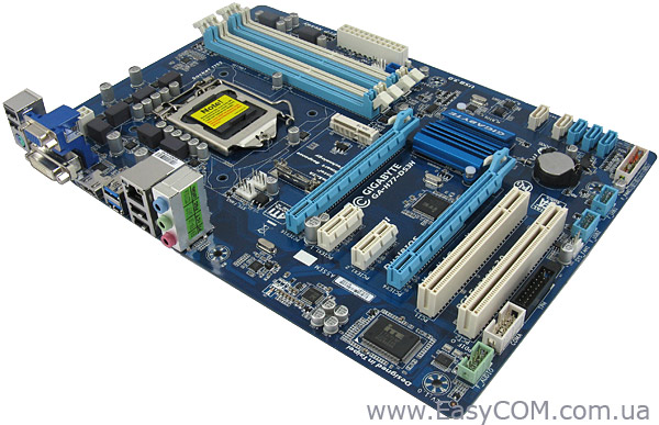
Рассматриваемая сегодня материнская плата от компании GIGABYTE основана на чипсете Intel H77 Express, который относится к массовому сегменту. От старших «братьев» Intel Z77 Express и Intel Z75 Express чипсет Intel H77 Express отличает официальной поддержкой только лишь одного полноценного разъема PCI Express 3.0 и отсутствие возможности разгона процессоров с разблокированным множителем. Таким образом, можно сказать, что материнская плата GIGABYTE GA-H77-DS3H адресуется в первую очередь домашним пользователям, не заинтересованным в разгоне. Так же материнская плата будет вполне уместна в небольшом офисе, где попросту не нужны дополнительные возможности корпоративных чипсетов Intel B75 Express, Intel Q77 Express и Intel Q75 Express.
Спецификация материнской платы GIGABYTE GA-H77-DS3H:
|
Производитель |
GIGABYTE |
|
Модель |
GA-H77-DS3H |
|
Чипсет |
Intel H77 |
|
Процессорный разъем |
Socket LGA1155 |
|
Поддерживаемые процессоры |
Intel Core i7/ Core i5 / Core i3 второго и третьего поколений |
|
Используемая память |
DDR3 1600*/1333/1066 МГц |
|
Поддержка памяти |
4 x DDR3 DIMM двухканальной архитектуры до 32 ГБ |
|
Слоты расширения |
1 x PCI Express x16 3.0 |
|
Multi-GPU |
CrossFireX в режиме х16+х4 |
|
Дисковая подсистема |
Чипсет Intel H77 поддерживает: |
|
Звуковая подсистема |
Realtek ALC887, 8-канальный High-Definition Audio кодек с оптическим выходом S/PDIF |
|
Поддержка LAN |
Atheros GbE 10/100/1000 Мбит/с |
|
Питание |
24-контактный разъем питания ATX |
|
Разъемы для вентиляторов |
1 x для процессорного кулера |
|
Внешние порты I/O |
1 x PS/2 (мышь или клавиатура) |
|
Внутренние порты I/O |
2 х SATA 6.0 Гбит/с |
|
BIOS |
2 x 64 Мбит Flash ROM, UEFI AMI BIOS, PnP 1.0a, DMI 2.0, WfM 2.0, ACPI v2.0a, SM BIOS 2.6, DualBIOS |
|
Фирменные технологии |
LAN Optimizer |
|
Комплектация |
Инструкция и руководство |
|
Форм-фактор Размеры, мм |
ATX |
|
Сайт производителя |
http://www.gigabyte.ua/ Свежая версия BIOS и драйверы могут быть скачаны со страницы загрузки. |
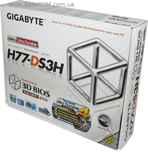
Материнская плата поставляется в компактной картонной коробке с качественной полиграфией. Львиную долю лицевой стороны упаковки занимает большая эмблема технологии 3D BIOS. Рядом крупными буквами приводится наименование модели материнской платы. Кроме того, здесь можно найти несколько дополнительных пиктограмм, указывающих на те, или иные особенности материнской платы, большая часть которых свойственна чипсету Intel H77 Express. Отдельно стоит выделить пиктограмму, указывающую на наличие разъема mSATA на борту.
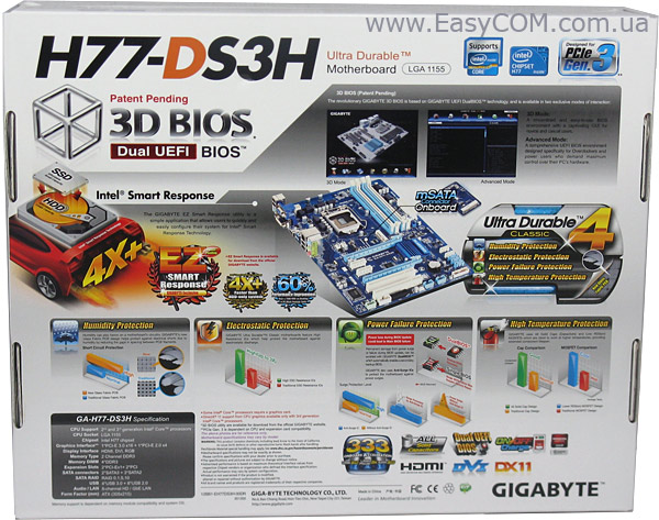
Задняя сторона коробки оформлена очень красочно. Здесь можно найти отметки о ключевых особенностях материнской платы. Большего всего внимания уделено фирменной концепции GIGABYTE Ultra Durable 4 Classic. В нее входят следующие технологии и нововведения:
-
Humidity Protection (защита от влажности) — технология производства печатных плат, которая предусматривает применение в качестве основы стекловолокна, у которого расстояние между волокнами сокращено, а узлы переплетения более плотные. Таким образом, влаге гораздо труднее проникнуть во внутренние слои. Это решение призвано обеспечить более надежную защиту материнской платы от короткого замыкания, вызванного сыростью.
-
Electrostatic Protection (Электростатическая защита) – подразумевает применение высококачественных микросхем с более высоким, по сравнению с традиционными компонентами, сопротивлением электростатического разряда.
-
Power Failure Protection (Защита от перепадов напряжения питания) – сюда производитель отнес технологию DualBIOS, позволяющую легко восстановить микропрограмму BIOS, а также дополнительные микросхемы, фильтрующие скачки напряжения.
-
High Temperature Protection (Защита от высокой температуры) – использование высококачественной элементной базы, которая способна выдерживать более высокие температуры даже в экстремальных условиях, на фоне надежной защиты ПК от перегрева.
Не стоит воспринимать данную материнскую плату, как промышленную – каких либо сертификатов (УкрСЕПРО, IEC), подтверждающих возможность стабильной работы в более жестких условиях, нет.
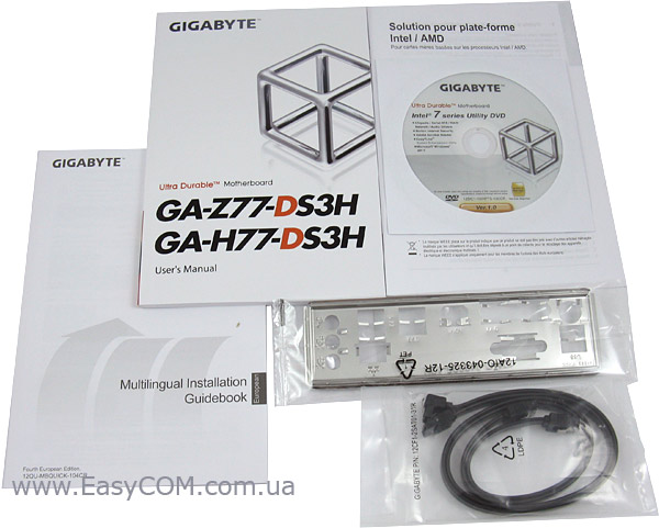
Комплектация у материнской платы GIGABYTE GA-H77-DS3H весьма скромная, все-таки плата относится к бюджетному сегменту:
-
DVD-диск с ПО и драйверами;
-
руководство пользователя и краткая инструкция по установке;
-
два шлейфа Serial ATA 6.0 Гбит/с;
-
заглушку на заднюю панель корпуса.

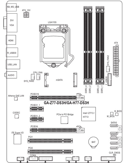
Компоновка материнской платы GIGABYTE GA-H77-DS3H выполнена вполне грамотно. Но поскольку материнская плата немного уже, чем принятый стандарт ATX – только 305 х 215 мм вместо 305 х 244 мм, то на материнской плате не осталось места для монтажных отверстий по правым углам платы, поэтому при сборке компьютера нужно проявить осторожность. В остальном компоновка элементов типична, и каких-либо трудностей вызвать не должна.
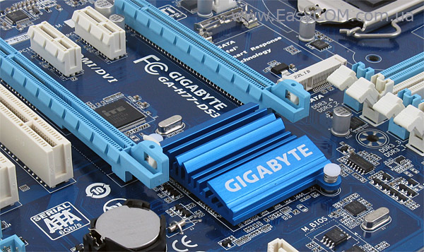
Для охлаждения PCH Intel H77 Express на материнской плате GIGABYTE GA-H77-DS3H используется стилизованный низкопрофильный алюминиевый радиатор. Во время тестирования радиатор нагревался до температуры 46ºC, что является хорошим показателем.
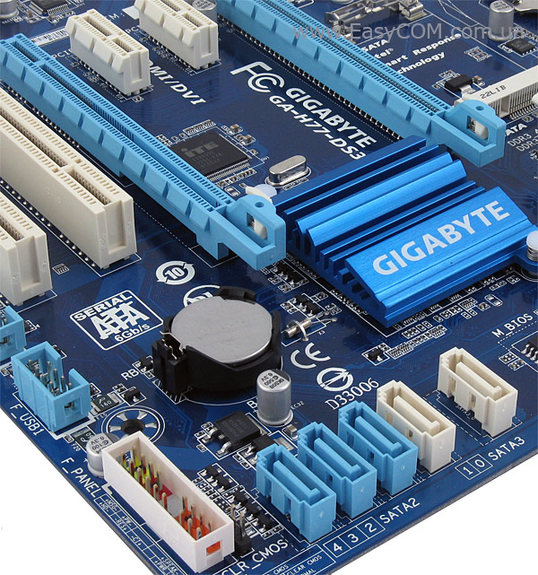
Дисковая подсистема материнской платы GIGABYTE GA-H77-DS3H основана на чипсете Intel H77 Express, который поддерживает три порта SATA 3 Гбит/c и два порта SATA 6 Гбит/c с возможностью организации RAID-массивов уровней 0, 1, 5 и 10. Разъем mSATA реализован за счет одного из портов SATA 3 Гбит/с, именно поэтому их осталось три, а не четыре, как свойственно чипсету Intel H77 Express.
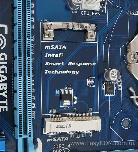
Разъем mSATA обеспечивает возможность установки SSD-накопителей с соответствующим интерфейсом для увеличения быстродействие системы. Это происходит за счёт кэширования данных на SSD-накопитель в соответствии с возможностями технологии Intel Smart Response Technology. Расположение порта mSATA выбрано удачно, да и размер накопителя совсем невелик, а значит, каких-либо неудобств такая система не вызовет.
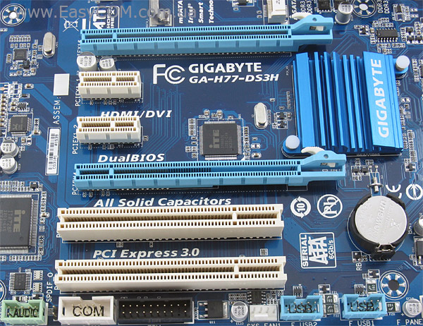
На материнской плате GIGABYTE GA-H77-DS3H имеется два слота PCI Express x16. Верхний слот использует 16 линий PCI Express 3.0, а нижний слот PCI Express x16 работает лишь с четырьмя линиями PCI Express 2.0 вне зависимости от режима. Расположение PEG разъемов позволяет использовать видеоадаптеры с «двухэтажной» системой охлаждения, но использование двух «топовых» видеоускоритлей не будет оправданным из-за невысокой пропускной способности слота PCI Express x16 2.0. Кроме того, на материнской плате имеется еще два слота PCI Express х1 и два слота PCI. Также, если установить крупногабаритный видеоадаптер в разъем PCI Express x16 2.0, то он перекроет доступ к портам SATA
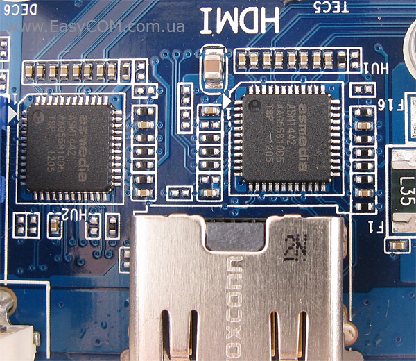
За переключение видеовыходов HDMI и DVI отвечает достаточно распространенная микросхема ASMedia ASM1442.
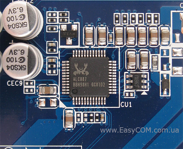
В качестве звукового кодека на GIGABYTE GA-H77-DS3H используется достаточно распространенный и хорошо себя зарекомендовавший 8-канальный HDA-кодек Realtek ALC887.
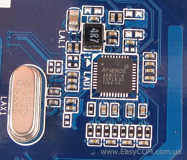
Для подключения к локальной сети на материнской плате GIGABYTE GA-H77-DS3H используется гигабитный сетевой контроллер Atheros AR8151. Эта микросхема не так часто используется производителями материнских плат, но зарекомендовала себя как вполне надежный компонент.
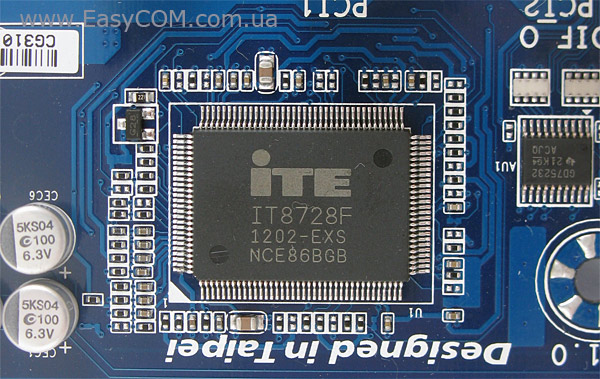
За реализацию COM-порта, а также слежение за температурой и скоростью вращения вентиляторов отвечает микросхема ITE IT8728F.
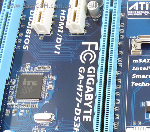
Так как чипсет Intel H77 Express не поддерживает работу с шиной PCI, то производитель установил мост PCI Express to PCI. Функцию моста выполняет микросхема ITE IT8892E.
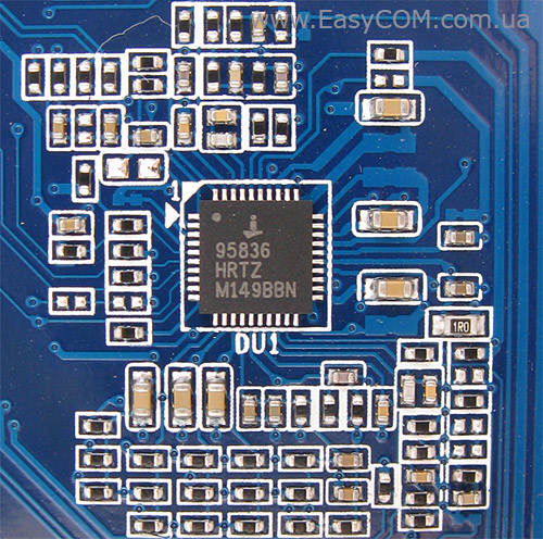
Основной преобразователь напряжения питания процессора выполнен по схеме 3+1+1 фазы. Две фазы используется для питания системного агента и видеоядра, а еще три для питания ядер процессора. В качестве ШИМ-контроллера используется микросхема Intersil ISL95836. Поскольку материнская плата принадлежит к серии Ultra Durable 4 Classic, то все используемые конденсаторы полимерные, а дроссели с ферритовыми сердечниками. Дополнительное охлаждение узла питания процессора отсутствует. Но поскольку возможность разгона не предусмотрена, то это вполне оправдано.
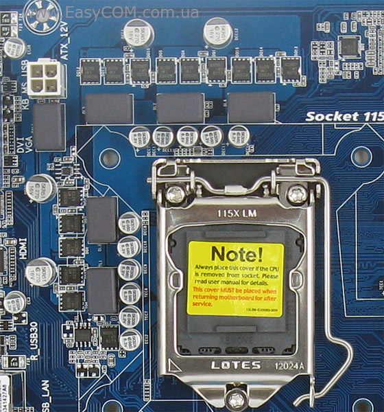
Питание к процессору подводится через 4-контактный разъем ATX 12V, но если не использовать hi-end процессоры Intel Core i7, то по этому поводу можно не переживать.
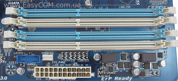
На материнской плате GIGABYTE GA-H77-DS3H установлено четыре 240-контактных разъема DIMM двухканальной архитектуры под оперативную память стандарта DDR3. Максимальный общий объем памяти может достигать 32 ГБ при установке четырех модулей емкостью 8 ГБ. Для организации работы памяти в двухканальном режиме необходимо заполнять разъемы одного цвета. Питание модулей памяти построено по двухфазной схеме.
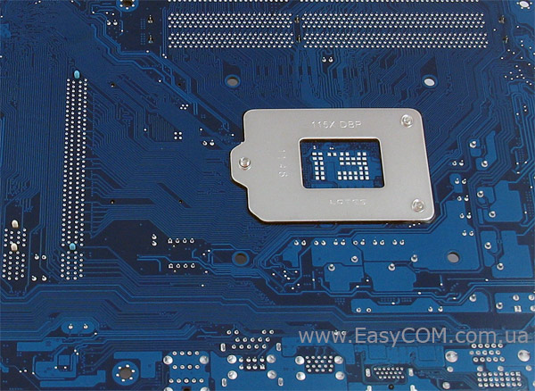
Обратная сторона материнской платы примечательна наличием крупной опорной пластины, которая придает дополнительную жесткость при креплении процессорного кулера.
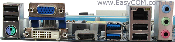
На интерфейсную панель материнской платы GIGABYTE GA-H77-DS3H выведены следующие порты:
- 1 x PS/2 (мышь / клавиатура);
- 4x USB 2.0;
- 2x USB 3.0;
- HDMI;
- DVI;
- VGA;
- разъем RJ45 для сетевых соединений;
- три разъема для 8-канального звука.
Количество портов типично для бюджетного решения, но зато есть порт PS/2, он пригодится в случае модернизации компьютера, если осталась клавиатура или мышь с таким интерфейсом. Но не хватает разъема DisplayPort и оптического аудиовыхода, а также полноценного набора аналоговых аудиовыходов, что позволило бы назвать плату универсальным решением для домашней мультимедийной системы.
Материнская плата GIGABYTE GA-H77-DS3H располагает четырьмя разъемами для подключения вентиляторов. Один разъем предназначен для подключения процессорного кулера, а остальные — для подключения корпусных вентиляторов. Все разъемы четырехконтактные, благодаря чему все вентиляторы управляемы.
UEFI BIOS
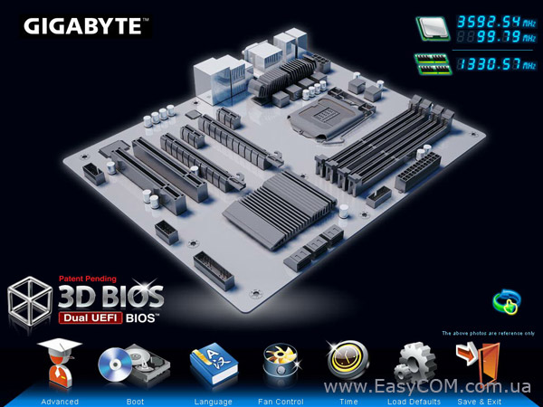
На материнской плате GIGABYTE GA-H77-DS3H используется UEFI на основе микропрограммы AMI с красочным графическим интерфейсом, который допускает управление с помощью мышки.
Интерфейс располагает двумя режимами работы, один из которых – 3D BIOS. Этот режим отличает наглядность – наведя указатель мышки на какой-либо компонент, пользователь увидит перечень настроек, доступных для изменения, касающихся этого компонента. Внизу экрана есть ряд пиктограмм, напоминающий Dashboard в MacOS X, который позволяет быстро и удобно вызвать некоторые пункты настроек.
Основная часть настроек, касающихся разгона системы сосредоточены в разделе MB Intelligent Tweaker (M.I.T.).
Настройки, необходимые для разгона, сведены таблицу:
|
Параметр |
Название меню |
Диапазон |
Шаг |
|
Частота системной шины, МГц |
CPU/PCIe Base Clock |
80 – 150 |
0,1 |
|
Частота встроенного графического ядра, МГц |
Internal Graphics Clock |
400 – 1600 |
50 |
|
Процессорные технологии |
C1E, C3/C6 State, EIST, CPU Thermal Monitor |
||
|
Процессорный множитель |
CPU Clock Ratio |
16 – 34 (определяется процессором) |
1 |
|
Делитель для памяти |
System Memory Multipllier |
8, 10.66, 13.33 |
|
|
Задержки ОЗУ |
CAS Latency, tRCD, tRP, tRAS, tRC, tRRD, tWTR, tWR, tWTP, tWL, tRFC, tRTP, tFAW, tCMD, tREFI, tRRDR, tRRDD, tWWDR, tWWDD, tRWDRDD, tWRDRDD, tRWSR, tRRSR, tWWSR |
||
|
Напряжение на модулях памяти, Вт |
DRAM Voltage |
1,14 – 2,1 |
0,01 |
Производить разгон процессора на материнской плате с чипсетом Intel H77 Express с помощью множителей возможности нет. А разгонять с помощью увеличения частоты системной шины больше, чем на 5-7% не получится, т.к. к частоте системной шины привязаны частоты шин SATA и PCIE. Поэтому увеличение частоты BCLK очень быстро приводит к потере стабильности.
Множитель частоты памяти позволяет устанавливать частоту от 800 МГц до 1333 МГц, хотя при использовании модулей с XMP-профилем частота может быть увеличена и до 1600 МГц.
Кроме разгона памяти материнская плата GIGABYTE GA-H77-DS3H способна производить разгон встроенного в процессор графического ядра с шагом 50 МГц от 400 МГц до 1600 МГц.
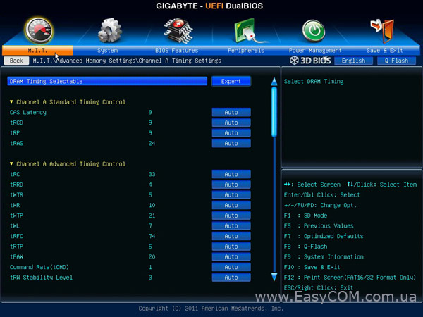
Настроить тайминги и подтайминги оперативной памяти можно в разделе «Advanced Memory Settings».
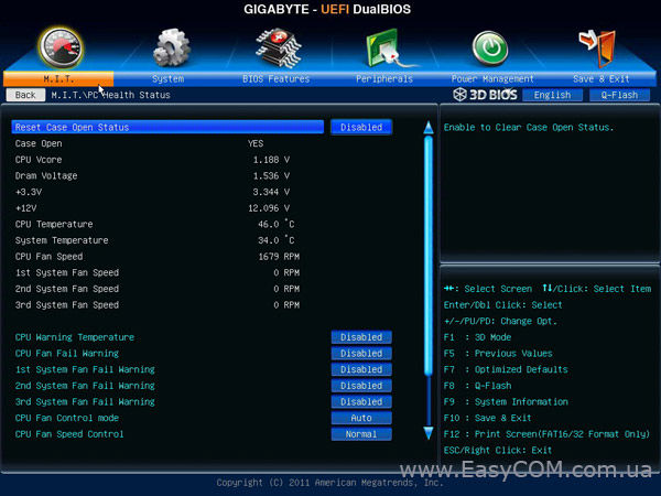
В разделе мониторинга PC Health Status можно следить за:
-
температурой материнской платы и процессора;
-
скоростью вращения процессорного кулера и четырех корпусных вентиляторов;
-
напряжением на ядре процессора;
-
напряжением на памяти;
-
напряжением на линиях питания +12В и +3,3В.
Кроме того, в этом разделе можно включить функцию автоматического управления процессорным кулером и корпусными вентиляторами, которые имеют различные режимы интенсивности.
Тестирование
Для проверки возможностей материнских плат использовалось следующее оборудование:
|
Процессор |
Intel Core i5-2500K (LGA1155, 3,3 ГГц, L3 6 МБ) |
|
Кулер |
Scythe Kama Angle Rev.B |
|
Оперативная память |
2x DDR3-2000 1024 МБ Kingston HyperX KHX16000D3T1K3/3GX |
|
Видеокарта |
MSI R4850-2D1G-OC (Radeon HD 4850, 1 ГБ GDDR3, PCIe 2.0) |
|
Жесткий диск |
Seagate Barracuda 7200.12 ST3500418AS, 500 ГБ, SATA-300, NCQ |
|
Оптический привод |
ASUS DRW-1814BLT SATA |
|
Блок питания |
Seasonic SS-650JT Active PFC (650 Вт, 120 ммвентилятор) |
|
Корпус |
CODEGEN M603 MidiTower (2х 120 мм вентилятора на вдув/выдув) |
Результаты тестов:
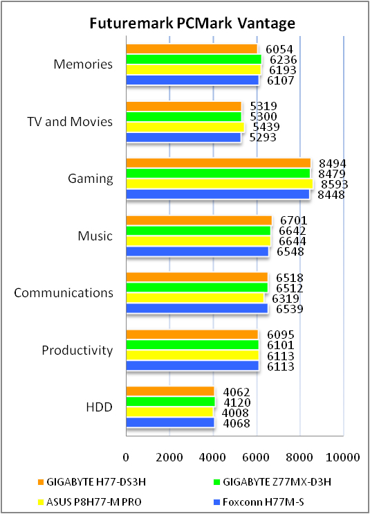
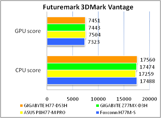
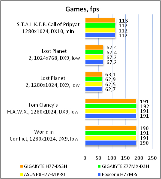
Материнская плата GIGABYTE GA-H77-DS3H показала такой же уровень производительности, как и другие участники теста. Это говорит о хорошем уровне исполнения платы и хорошей оптимизации микропрограммы.
Тестирование звукового тракта на основе кодека Realtek ALC887
Общие результаты (RightMark Audio Analyzer)
16-bit, 44,1 kHz
|
Неравномерность АЧХ (в диапазоне 40 Гц — 15 кГц), дБ |
+0.12, -0.18 |
Очень хорошо |
|
Уровень шума, дБ (А) |
-86.4 |
Хорошо |
|
Динамические диапазон, дБ (А) |
86.2 |
Хорошо |
|
Гармонические искажения, % |
0.0033 |
Очень хорошо |
|
Гармонические искажения + шум, дБ(A) |
-76.9 |
Средне |
|
Интермодуляционные искажения + шум, % |
0.017 |
Очень хорошо |
|
Взаимопроникновение каналов, дБ |
-81.4 |
Очень хорошо |
|
Интермодуляции на 10 кГц, % |
0.017 |
Очень хорошо |
|
Общая оценка |
Хорошо |
24-bit, 192 kHz
|
Неравномерность АЧХ (в диапазоне 40 Гц — 15 кГц), дБ |
+0.05, -0.10 |
Отлично |
|
Уровень шума, дБ (А) |
-86.0 |
Хорошо |
|
Динамические диапазон, дБ (А) |
86.4 |
Хорошо |
|
Гармонические искажения, % |
0.0029 |
Отлично |
|
Гармонические искажения + шум, дБ(A) |
-78.0 |
Средне |
|
Интермодуляционные искажения + шум, % |
0.016 |
Очень хорошо |
|
Взаимопроникновение каналов, дБ |
-78.6 |
Очень хорошо |
|
Интермодуляции на 10 кГц, % |
0.017 |
Очень хорошо |
|
Общая оценка |
Хорошо |
Аудиоподсистема получила среднюю оценку «Хорошо». Это означает, что можно получить достаточно хорошее качество звучания без приобретения дискретной звуковой карты. Но если выдвигаются серьезные требования к качеству аудиосопровождения, то встроенного аудиокодека будет недостаточно.
Выводы
Материнская плата GIGABYTE GA-H77-DS3H будет отличной основой для домашнего производительного ПК среднестатистического пользователя у которого нет многоканальной аудисосистемы. Как вариант плату можно было бы использовать и для построения офисного компьютера. Однако, на момент написания обзора стоимость платы колебалась вокруг отметки в 100$, что не позволяет охарактеризовать её как оптимальный выбор. Тем более, при сборке домашнего компьютера можно добавить 20-30 USD и купить материнскую плату на чипсете Intel Z77 Express из недорогой серии, которая будет чуть более функциональной и перспективной «на вырост». Наличие разъема mSATA – спорное преимущество, если SSD накопителя нет в комплекте, т.к. такой накопитель не в каждом магазине можно купить, да и не самое дешевое это удовольствие – стоимость такого диска в рознице около 50 USD. С другой стороны покупатели этой материнской платы получат качественную элементную базу, аудиокодек с хорошим качеством звучания, хотя и ограничивающий подключение многоканальных аудиосистем. При этом если производитель немного снизит стоимость материнской платы, то GIGABYTE GA-H77-DS3H будет отличным приобретением.
Достоинства:
-
поддержка всех наиболее распространенных видеовыходов;
-
наличие интерфейса mSATA для простого использования Intel SRT;
-
качественная элементная база;
-
качественный 8-канальный звуковой кодек;
-
поддержка интерфейсов COM и PS/2.
Недостатки:
-
скромный комплект поставки;
-
завышенная цена;
-
отсутствие оптического выхода на задней панели;
-
наличие лишь трех аналоговых аудиовыходов.
Особенности:
-
поддержка технологии AMD CrossFireX, но низкая практическая ценность второго PEG слота, работающего в режиме 4x;
-
отсутствие монтажных отверстий в углах на правой стороне.

Автор: Александр Корниенко
Выражаем благодарность компании MTI, официальному дистрибьютору продукции GIGABYTE, за предоставленную для тестирования материнскую плату.
Выражаем благодарность компаниям Intel, Kingston, MSI и SeaSonic за предоставленное для тестового стенда оборудование.
View a manual of the Gigabyte GA-H77-DS3H below. All manuals on ManualsCat.com can be viewed completely free of charge. By using the ‘Select a language’ button, you can choose the language of the manual you want to view.
Page: 1
Motherboard
GA-Z77-DS3H/
GA-H77-DS3H
Mar.
15,
2012
Mar.
15,
2012
Motherboard
GA-Z77-DS3H
GA-H77-DS3H
Page: 2
Copyright
© 2012 GIGA-BYTE TECHNOLOGY CO., LTD. All rights reserved.
The trademarks mentioned in this manual are legally registered to their respective owners.
Disclaimer
Information in this manual is protected by copyright laws and is the property of GIGABYTE.
Changes to the specifications and features in this manual may be made by GIGABYTE without
prior notice. No part of this manual may be reproduced, copied, translated, transmitted, or
published in any form or by any means without GIGABYTE’s prior written permission.
Documentation Classifications
In order to assist in the use of this product, GIGABYTE provides the following types of
documentations:
For quick set-up of the product, read the Quick Installation Guide included with the product.
For detailed product information, carefully read the User’s Manual.
For product-related information, check on our website at: http://www.gigabyte.com
Identifying Your Motherboard Revision
The revision number on your motherboard looks like this: «REV: X.X.» For example, «REV:
1.0» means the revision of the motherboard is 1.0. Check your motherboard revision before
updating motherboard BIOS, drivers, or when looking for technical information.
Example:
Page: 3
— 4 —
Table of Contents
Box Contents……………………………………………………………………………………………………..6
Optional Items……………………………………………………………………………………………………6
GA-Z77-DS3H/GA-H77-DS3H Motherboard Layout………………………………………………..7
GA-Z77-DS3H/GA-H77-DS3H Motherboard Block Diagram……………………………………..8
Chapter 1 Hardware Installation…………………………………………………………………………..9
1-1 Installation Precautions…………………………………………………………………………. 9
1-2 Product Specifications…………………………………………………………………………. 10
1-3 Installing the CPU and CPU Cooler………………………………………………………. 13
1-3-1 Installing the CPU……………………………………………………………………………………….13
1-3-2 Installing the CPU Cooler…………………………………………………………………………….15
1-4 Installing the Memory………………………………………………………………………….. 16
1-4-1 Dual Channel Memory Configuration…………………………………………………………………16
1-4-2 Installing a Memory…………………………………………………………………………………….17
1-5 Installing an Expansion Card……………………………………………………………….. 18
1-6 Back Panel Connectors……………………………………………………………………….. 19
1-7 Internal Connectors…………………………………………………………………………….. 21
Chapter 2 BIOS Setup………………………………………………………………………………………31
2-1 Startup Screen…………………………………………………………………………………… 32
2-2 The Main Menu………………………………………………………………………………….. 33
2-3 M.I.T…………………………………………………………………………………………………. 35
2-4 System……………………………………………………………………………………………… 44
2-5 BIOS Features…………………………………………………………………………………… 45
2-6 Peripherals………………………………………………………………………………………… 47
2-7 Power Management……………………………………………………………………………. 51
2-8 Save & Exit………………………………………………………………………………………… 53
Chapter 3 Drivers Installation……………………………………………………………………………..55
3-1 Installing Chipset Drivers…………………………………………………………………….. 55
3-2 Application Software…………………………………………………………………………… 56
3-3 Technical Manuals………………………………………………………………………………. 56
3-4 Contact……………………………………………………………………………………………… 57
Page: 4
— 5 —
3-5 System……………………………………………………………………………………………… 57
3-6 Download Center……………………………………………………………………………….. 58
3-7 New Program…………………………………………………………………………………….. 58
Chapter 4 Unique Features………………………………………………………………………………..59
4-1 Xpress Recovery2………………………………………………………………………………. 59
4-2 BIOS Update Utilities………………………………………………………………………….. 62
4-2-1 Updating the BIOS with the Q-Flash Utility……………………………………………………..62
4-2-2 Updating the BIOS with the @BIOS Utility……………………………………………………..65
4-3 EasyTune 6……………………………………………………………………………………….. 66
4-4 Q-Share…………………………………………………………………………………………….. 67
4-5 eXtreme Hard Drive (X.H.D)………………………………………………………………… 68
4-6 Auto Green………………………………………………………………………………………… 69
4-7 EZ Setup…………………………………………………………………………………………… 70
4-7-1 Installing EZ Smart Response………………………………………………………………………71
4-7-2 Installing EZ Rapid Start………………………………………………………………………………72
4-7-3 Installing EZ Smart Connect…………………………………………………………………………73
Chapter 5 Appendix………………………………………………………………………………………….75
5-1 Configuring SATA Hard Drive(s)……………………………………………………………. 75
5-1-1 Configuring SATA Controllers……………………………………………………………………….75
5-1-2 Installing the SATA RAID/AHCI Driver and Operating System…………………………..83
5-2 Configuring Audio Input and Output………………………………………………………. 88
5-2-1 Configuring 2/4/5.1/7.1-Channel Audio…………………………………………………………..88
5-2-2 Configuring S/PDIF Out……………………………………………………………………………….90
5-2-3 Configuring Microphone Recording……………………………………………………………….91
5-2-4 Using the Sound Recorder…………………………………………………………………………..93
5-3 Troubleshooting…………………………………………………………………………………. 94
5-3-1 Frequently Asked Questions ………………………………………………………………………..94
5-3-2 Troubleshooting Procedure………………………………………………………………………….95
5-3-3 Regulatory Statements………………………………………………………………………………..97
Page: 5
— 6 —
Box Contents
;
; GA-Z77-DS3H or GA-H77-DS3H motherboard
;
; Motherboard driver disk
;
; User’s Manual
;
; Quick Installation Guide
;
; Two SATA 6Gb/s cables
;
; I/O Shield
Optional Items
2-port USB 2.0 bracket (Part No. 12CR1-1UB030-6*R)
eSATA bracket (Part No. 12CF1-3SATPW-4*R)
3.5″ Front Panel with 2 USB 3.0/2.0 ports (Part No. 12CR1-FPX582-0*R)
HDMI-to-DVI adapter (Part No. 12CT2-HDMI01-1*R)
COM port cable (Part No. 12CF1-1CM001-3*R)
The box contents above are for reference only and the actual items shall depend on the product package you obtain.
The box contents are subject to change without notice.
Page: 6
— 7 —
GA-Z77-DS3H/GA-H77-DS3H Motherboard Layout
j Only for GA-Z77-DS3H.
k Only for GA-H77-DS3H.
KB_MS_USB
SYS_FAN2
ATX_12V_2X4
ATX
AUDIO
B_BIOS
PCIEX4
DDR3_4
DDR3_2
BAT
Intel® Z77j/
H77k
CLR_CMOS
CPU_FAN
M_BIOS
PCIEX16
PCIEX1_1
F_USB2
LGA1155
GA-Z77-DS3H/GA-H77-DS3H
DVI
R_USB30
VGA
iTE Super I/O
F_USB1
PCIEX1_2
COMA
F_AUDIO TPM
HDMI
PCI2
SATA3
0
1
Atheros GbE LAN
USB_LAN
SYS_FAN1
CODEC
mSATA
DDR3_3
DDR3_1
SATA2
F_USB30
SYS_FAN3
F_PANEL
PCIe to PCI Bridge
2
3
4
PCI1
SPDIF_O
Page: 7
— 8 —
GA-Z77-DS3H/GA-H77-DS3H Motherboard Block Diagram
LGA1155
CPU
Intel® Z77j/
H77k
PCI Express Bus
CPU CLK+/- (100 MHz)
PCIe CLK
(100 MHz)
Dual Channel Memory
1 PCI Express x16
x16
PCI Express Bus
LAN
RJ45
Atheros
GbE LAN
PS/2 KB/Mouse
COM
iTE
Super I/O
LPC
Bus
2 PCI
PCI Bus
PCI CLK
(33 MHz)
PCIe to PCI
Bridge
x1
x4 x1
2 PCI Express x1
1 PCI Express x4
CODEC
Line
In
(Rear
Speaker
Out)
Line
Out
(Front
Speaker
Out)
MIC
(Center/Subwoofer
Speaker
Out)
DDR3 1600/1333/1066 MHz
DMI
2.0
FDI
S/PDIF
Out
8 USB 2.0/1.1
Dual BIOS
2 SATA 6Gb/s
HDMI
3 SATA 3Gb/s
1 mSATA
4 USB 3.0/2.0
D-Sub
x1
DVI
j Only for GA-Z77-DS3H.
k Only for GA-H77-DS3H.
For detailed product information/limitation(s), refer to «1-2 Product Specifications.»
Page: 8
— 9 — Hardware Installation
1-1 Installation Precautions
The motherboard contains numerous delicate electronic circuits and components which can become
damaged as a result of electrostatic discharge (ESD). Prior to installation, carefully read the user’s
manual and follow these procedures:
•
• Prior to installation, make sure the chassis is suitable for the motherboard.
•
• Prior to installation, do not remove or break motherboard S/N (Serial Number) sticker or warranty
sticker provided by your dealer. These stickers are required for warranty validation.
•
• Always remove the AC power by unplugging the power cord from the power outlet before
installing or removing the motherboard or other hardware components.
•
• When connecting hardware components to the internal connectors on the motherboard, make
sure they are connected tightly and securely.
•
• When handling the motherboard, avoid touching any metal leads or connectors.
•
• It is best to wear an electrostatic discharge (ESD) wrist strap when handling electronic
components such as a motherboard, CPU or memory. If you do not have an ESD wrist strap,
keep your hands dry and first touch a metal object to eliminate static electricity.
•
• Prior to installing the motherboard, please have it on top of an antistatic pad or within an
electrostatic shielding container.
•
• Before unplugging the power supply cable from the motherboard, make sure the power supply
has been turned off.
•
• Before turning on the power, make sure the power supply voltage has been set according to
the local voltage standard.
•
• Before using the product, please verify that all cables and power connectors of your hardware
components are connected.
•
• To prevent damage to the motherboard, do not allow screws to come in contact with the
motherboard circuit or its components.
•
• Make sure there are no leftover screws or metal components placed on the motherboard or
within the computer casing.
•
• Do not place the computer system on an uneven surface.
•
• Do not place the computer system in a high-temperature environment.
•
• Turning on the computer power during the installation process can lead to damage to system
components as well as physical harm to the user.
•
• If you are uncertain about any installation steps or have a problem related to the use of the
product, please consult a certified computer technician.
Chapter 1 Hardware Installation
Page: 9
— 10 —
Hardware Installation
1-2 Product Specifications
CPU Support for Intel®
Core™ i7 processors/Intel®
Core™ i5 processors/
Intel®
Core™ i3 processors/Intel®
Pentium®
processors/
Intel®
Celeron®
processors in the LGA1155 package
(Go to GIGABYTE’s website for the latest CPU support list.)
L3 cache varies with CPU
Chipset Intel®
Z77j/Intel®
H77k Express Chipset
Memory
4 x 1.5V DDR3 DIMM sockets supporting up to 32 GB of system memory
* Due to a Windows 32-bit operating system limitation, when more than 4 GB of physical
memory is installed, the actual memory size displayed will be less than the size of
the physical memory installed.
Dual channel memory architecture
Support for DDR3 1600/1333/1066 MHz memory modules
*
To support DDR3 1600 MHz, you must install an Intel 22nm (Ivy Bridge) CPU.
Support for non-ECC memory modules
Support for Extreme Memory Profile (XMP) memory modules
*
To support XMP memory, you must install an Intel 22nm (Ivy Bridge) CPU.k
(Go to GIGABYTE’s website for the latest supported memory speeds and memory
modules.)
Onboard
Graphics
Integrated Graphics Processor:
— 1 x D-Sub port
—
1 x DVI-D port, supporting a maximum resolution of 1920×1200
* The DVI-D port does not support D-Sub connection by adapter.
—
1 x HDMI port, supporting a maximum resolution of 1920×1200
Audio Realtek ALC887 codec
High Definition Audio
2/4/5.1/7.1-channel
* To configure 7.1-channel audio, you have to use an HD front panel audio module
and enable the multi-channel audio feature through the audio driver.
Support for S/PDIF Out
LAN Atheros GbE LAN chip (10/100/1000 Mbit)
Expansion Slots 1 x PCI Express x16 slot, running at x16 (PCIEX16)
(The PCIEX16 slot conforms to PCI Express 3.0 standard.)
*
For optimum performance, if only one PCI Express graphics card is to be installed,
be sure to install it in the PCIEX16 slot.
* Whether PCI Express 3.0 is supported depends on CPU and graphics card compat-
ibility.
1 x PCI Express x16 slot, running at x4 (PCIEX4)
2 x PCI Express x1 slots
(The PCIEX4 and PCI Express x1 slots conform to PCI Express 2.0 standard.)
2 x PCI slots
Multi-Graphics
Technology
Support for AMD CrossFireX™
technology
j Only for GA-Z77-DS3H.
k Only for GA-H77-DS3H.
Page: 10
— 11 — Hardware Installation
Storage Interface Chipset:
— 2 x SATA 6Gb/s connectors (SATA3 0/1) supporting up to 2 SATA 6Gb/s
devices
— 3 x SATA 3Gb/s connectors (SATA2 2/3/4) supporting up to 3 SATA 3Gb/s
devices
— 1 x mSATA connector
— Support for RAID 0, RAID 1, RAID 5, and RAID 10
* When a RAID set is built across the SATA 6Gb/s and SATA 3Gb/s channels, the
system performance of the RAID set may vary depending on the devices being
connected.
USB Chipset:
— Up to 4 USB 3.0/2.0 ports (2 ports on the back panel, 2 ports available through
the internal USB header)
* In Windows XP, the Intel USB 3.0 ports can support up to USB 2.0 transfer speed.
— Up to 8 USB 2.0/1.1 ports (4 ports on the back panel, 4 ports available through
the internal USB headers)
Internal
Connectors
1 x 24-pin ATX main power connector
1 x 8-pin ATX 12V power connector
2 x SATA 6Gb/s connectors
3 x SATA 3Gb/s connectors
1 x mSATA connector
1 x CPU fan header
3 x system fan headers
1 x front panel header
1 x front panel audio header
1 x S/PDIF Out header
2 x USB 2.0/1.1 headers
1 x USB 3.0/2.0 header
1 x Clear CMOS jumper
1 x serial port header
1 x Trusted Platform Module (TPM) header
Back Panel
Connectors
1 x PS/2 keyboard/mouse port
1 x D-Sub port
1 x DVI-D port
1 x HDMI port
4 x USB 2.0/1.1 ports
2 x USB 3.0/2.0 ports
1 x RJ-45 port
3 x audio jacks (Line In/Line Out/Microphone)
Page: 11
— 12 —
Hardware Installation
I/O Controller iTE I/O Controller Chip
Hardware
Monitor
System voltage detection
CPU/System temperature detection
CPU/System fan speed detection
CPU overheating warning
CPU/System fan fail warning
CPU/System fan speed control
* Whether the CPU/system fan speed control function is supported will depend on the
CPU/system cooler you install.
BIOS 2 x 64 Mbit flash
Use of licensed AMI EFI BIOS
Support for DualBIOS™
PnP 1.0a, DMI 2.0, SM BIOS 2.6, ACPI 2.0a
Unique Features
Support for @BIOS
Support for Q-Flash
Support for Xpress Install
Support for Xpress Recovery2
Support for EasyTune
* Available functions in EasyTune may differ by motherboard model.
Support for eXtreme Hard Drive (X.H.D)
Support for Auto Green
Support for ON/OFF Charge
Support for Q-Share
Support for EZ Setup
Bundled
Software
Norton Internet Security (OEM version)
Intel®
Smart Response Technology
Intel®
Rapid Start Technology
Intel®
Smart Connect Technology
Operating
System
Support for Microsoft®
Windows 7/XP
Form Factor ATX Form Factor; 30.5cm x 21.5cm
* GIGABYTE reserves the right to make any changes to the product specifications and product-related information without
prior notice.
* Please visit GIGABYTE’s website to check the supported operating system(s) for the software listed in the «Unique
Features» and «Bundled Software» columns.
Page: 12
— 13 — Hardware Installation
1-3 Installing the CPU and CPU Cooler
Read the following guidelines before you begin to install the CPU:
•
• Make sure that the motherboard supports the CPU.
(Go to GIGABYTE’s website for the latest CPU support list.)
•
• Always turn off the computer and unplug the power cord from the power outlet before installing the
CPU to prevent hardware damage.
•
• Locate the pin one of the CPU. The CPU cannot be inserted if oriented incorrectly. (Or you may
locate the notches on both sides of the CPU and alignment keys on the CPU socket.)
•
• Apply an even and thin layer of thermal grease on the surface of the CPU.
•
• Do not turn on the computer if the CPU cooler is not installed, otherwise overheating and damage
of the CPU may occur.
•
• Set the CPU host frequency in accordance with the CPU specifications. It is not recommended
that the system bus frequency be set beyond hardware specifications since it does not meet the
standard requirements for the peripherals. If you wish to set the frequency beyond the standard
specifications, please do so according to your hardware specifications including the CPU, graphics
card, memory, hard drive, etc.
1-3-1 Installing the CPU
A. Locate the alignment keys on the motherboard CPU socket and the notches on the CPU.
Alignment Key
Alignment Key
LGA1155 CPU Socket
Pin One Corner of the CPU Socket
Notch
Notch
LGA1155 CPU
Triangle Pin One Marking on the CPU
Page: 13
— 14 —
Hardware Installation
B. Follow the steps below to correctly install the CPU into the motherboard CPU socket.
Before installing the CPU, make sure to turn off the computer and unplug the power cord from
the power outlet to prevent damage to the CPU.
Step 1:
Gently press the CPU socket lever handle down
and away from the socket with your finger. Then
completely lift the CPU socket lever and the metal
load plate will be lifted as well.
Step 3:
Hold the CPU with your thumb and index fingers.
Align the CPU pin one marking (triangle) with the
pin one corner of the CPU socket (or you may align
the CPU notches with the socket alignment keys)
and gently insert the CPU into position.
Step 5:
Push the CPU socket lever back into its locked
position.
Step 4:
Once the CPU is properly inserted, use one hand
to hold the socket lever and use the other to lightly
replace the load plate. When replacing the load
plate, make sure the front end of the load plate is
under the shoulder screw.
NOTE:
Hold the CPU socket lever by the handle, not the
lever base portion.
Step 2:
Remove the CPU socket cover as shown. Hold
your index finger down on the rear grip of the
socket cover and use your thumb to lift up the
front edge (next to the «REMOVE» mark) and
then remove the cover. (DO NOT touch socket
contacts. To protect the CPU socket, always
replace the protective socket cover when the CPU
is not installed.)
Page: 14
— 15 — Hardware Installation
1-3-2 Installing the CPU Cooler
Follow the steps below to correctly install the CPU cooler on the motherboard. (The following procedure uses
Intel®
boxed cooler as the example cooler.)
Use extreme care when removing the CPU cooler because the thermal grease/tape between the
CPU cooler and CPU may adhere to the CPU. Inadequately removing the CPU cooler may damage
the CPU.
Step 1:
Apply an even and thin layer of thermal grease on
the surface of the installed CPU.
Male
Push Pin
Female
Push Pin
The Top of
Female
Push Pin
Direction of
the Arrow Sign
on the Male
Push Pin
Step 2:
Before installing the cooler, note the direction of the
arrow sign on the male push pin. (Turning the
push pin along the direction of arrow is to remove
the cooler, on the contrary, is to install.)
Step 3:
Place the cooler atop the CPU, aligning the
four push pins through the pin holes on the
motherboard. Push down on the push pins
diagonally.
Step 4:
You should hear a «click» when pushing down each
push pin. Check that the Male and Female push
pins are joined closely.
(Refer to your CPU cooler installation manual for
instructions on installing the cooler.)
Step 5:
After the installation, check the back of the
motherboard. If the push pin is inserted as
the picture above shows, the installation is
complete.
Step 6:
Finally, attach the power connector of the CPU
cooler to the CPU fan header (CPU_FAN) on the
motherboard.
Page: 15
— 16 —
Hardware Installation
1-4 Installing the Memory
DDR3_4
DDR3_2
DDR3_3
DDR3_1
1-4-1 Dual Channel Memory Configuration
This motherboard provides four DDR3 memory sockets and supports Dual Channel Technology. After the
memory is installed, the BIOS will automatically detect the specifications and capacity of the memory. Enabling
Dual Channel memory mode will double the original memory bandwidth.
The four DDR3 memory sockets are divided into two channels and each channel has two memory sockets as
following:
Channel A: DDR3_2, DDR3_4
Channel B: DDR3_1, DDR3_3
Dual Channel Memory Configurations Table
(SS=Single-Sided, DS=Double-Sided, «- -«=No Memory)
DDR3_4 DDR3_2 DDR3_3 DDR3_1
Two Modules — — DS/SS — — DS/SS
DS/SS — — DS/SS — —
Four Modules DS/SS DS/SS DS/SS DS/SS
Due to CPU limitations, read the following guidelines before installing the memory in Dual Channel mode.
1. Dual Channel mode cannot be enabled if only one DDR3 memory module is installed.
2. When enabling Dual Channel mode with two or four memory modules, it is recommended that memory
of the same capacity, brand, speed, and chips be used and installed in the same colored DDR3
sockets. For optimum performance, when enabling Dual Channel mode with two memory modules,
we recommend that you install them in the DDR3_1 and DDR3_2 sockets.
Read the following guidelines before you begin to install the memory:
•
• Make sure that the motherboard supports the memory. It is recommended that memory of the same
capacity, brand, speed, and chips be used.
(Go to GIGABYTE’s website for the latest supported memory speeds and memory modules.)
•
• Always turn off the computer and unplug the power cord from the power outlet before installing the
memory to prevent hardware damage.
•
• Memory modules have a foolproof design.Amemory module can be installed in only one direction.
If you are unable to insert the memory, switch the direction.
Page: 16
— 17 — Hardware Installation
1-4-2 Installing a Memory
Before installing a memory module, make sure to turn off the computer and unplug the power cord
from the power outlet to prevent damage to the memory module. DDR3 and DDR2 DIMMs are not
compatible to each other or DDR DIMMs. Be sure to install DDR3 DIMMs on this motherboard.
Notch
DDR3 DIMM
ADDR3 memory module has a notch, so it can only fit in one direction. Follow the steps below to correctly install
your memory modules in the memory sockets.
Step 1:
Note the orientation of the memory module. Spread the retaining clips
at both ends of the memory socket. Place the memory module on the
socket. As indicated in the picture on the left, place your fingers on
the top edge of the memory, push down on the memory and insert it
vertically into the memory socket.
Step 2:
The clips at both ends of the socket will snap into place when the
memory module is securely inserted.
Page: 17
— 18 —
Hardware Installation
1-5 Installing an Expansion Card
Example: Installing and Removing a PCI Express Graphics Card:
PCI Express x1 Slot
PCI Express x16 Slot
PCI Slot
•
• Installing a Graphics Card:
Gently push down on the top edge of the card until
it is fully inserted into the PCI Express slot. Make
sure the card is securely seated in the slot and
does not rock.
Read the following guidelines before you begin to install an expansion card:
•
• Make sure the motherboard supports the expansion card. Carefully read the manual that came
with your expansion card.
•
• Always turn off the computer and unplug the power cord from the power outlet before installing an
expansion card to prevent hardware damage.
Follow the steps below to correctly install your expansion card in the expansion slot.
1. Locate an expansion slot that supports your card. Remove the metal slot cover from the chassis back
panel.
2. Align the card with the slot, and press down on the card until it is fully seated in the slot.
3. Make sure the metal contacts on the card are completely inserted into the slot.
4. Secure the card’s metal bracket to the chassis back panel with a screw.
5. After installing all expansion cards, replace the chassis cover(s).
6. Turn on your computer. If necessary, go to BIOS Setup to make any required BIOS changes for your
expansion card(s).
7. Install the driver provided with the expansion card in your operating system.
•
• Removing the Card:
Gently push back on the lever on the slot and then lift the card straight out from
the slot.
Page: 18
— 19 — Hardware Installation
1-6 Back Panel Connectors
USB 2.0/1.1 Port
The USB port supports the USB 2.0/1.1 specification. Use this port for USB devices such as a USB
keyboard/mouse, USB printer, USB flash drive and etc.
PS/2 Keyboard/Mouse Port
Use this port to connect a PS/2 mouse or keyboard.
D-Sub Port
The D-Sub port supports a 15-pin D-Sub connector. Connect a monitor that supports D-Sub connection
to this port.
DVI-D Port (Note)
The DVI-D port conforms to the DVI-D specification and supports a maximum resolution of 1920×1200
(the actual resolutions supported depend on the monitor being used). Connect a monitor that supports
DVI-D connection to this port.
HDMI Port
The HDMI port is HDCP compliant and supports Dolby True HD and DTS HD
MasterAudio formats. It also supports up to 192KHz/24bit 8-channel LPCM audio
output. You can use this port to connect your HDMI-supported monitor. The maximum supported resolution
is 1920×1200, but the actual resolutions supported are dependent on the monitor being used.
After installing the HDMI device, make sure to set the default sound playback device to HDMI.
(The item name may differ depending on your operating system. The screenshot below is from
Windows 7.)
In Windows 7, select Start>Control Panel>Hardware and
Sound>Sound>Playback, set Intel(R) DisplayAudio to the
default playback device.
(Note) The DVI-D port does not support D-Sub connection by adapter.
Dual Display Configurations for the Onboard Graphics:
This motherboard provides three video output ports: D-Sub, DVI-D, and HDMI. Dual monitor confgurations
are supported in operating system environment only, but not during the BIOS Setup or POST process.
Page: 19
— 20 —
Hardware Installation
USB 3.0/2.0 Port
The USB 3.0 port supports the USB 3.0 specification and is compatible to the USB 2.0/1.1 specification.
Use this port for USB devices such as a USB keyboard/mouse, USB printer, USB flash drive and etc.
RJ-45 LAN Port
The Gigabit Ethernet LAN port provides Internet connection at up to 1 Gbps data rate. The following
describes the states of the LAN port LEDs.
Line In Jack (Blue)
The default line in jack. Use this audio jack for line in devices such as an optical drive, walkman, etc.
Line Out Jack (Green)
The default line out jack. Use this audio jack for a headphone or 2-channel speaker. This jack can be
used to connect front speakers in a 4/5.1/7.1-channel audio configuration.
Mic In Jack (Pink)
The default Mic in jack. Microphones must be connected to this jack.
•
• When removing the cable connected to a back panel connector, first remove the cable from your
device and then remove it from the motherboard.
•
• When removing the cable, pull it straight out from the connector. Do not rock it side to side to prevent
an electrical short inside the cable connector.
To configure 7.1-channel audio, you have to use an HD front panel audio module and enable the multi-
channel audio feature through the audio driver. Refer to the instructions on setting up a 2/4/5.1/7.1-
channel audio configuration in Chapter 5, «Configuring 2/4/5.1/7.1-Channel Audio.»
Activity LED
Connection/
Speed LED
LAN Port
Activity LED:
Connection/Speed LED:
State Description
Orange 1 Gbps data rate
Green 100 Mbps data rate
Off 10 Mbps data rate
State Description
Blinking Data transmission or receiving is occurring
Off No data transmission or receiving is occurring
Page: 20
— 21 — Hardware Installation
1-7 Internal Connectors
Read the following guidelines before connecting external devices:
•
• First make sure your devices are compliant with the connectors you wish to connect.
•
• Before installing the devices, be sure to turn off the devices and your computer. Unplug the power
cord from the power outlet to prevent damage to the devices.
•
• After installing the device and before turning on the computer, make sure the device cable has
been securely attached to the connector on the motherboard.
1) ATX_12V_2X4
2) ATX
3) CPU_FAN
4) SYS_FAN1/2/3
5) SATA3 0/1
6) SATA2 2/3/4
7) mSATA
 BAT
BAT
9) F_PANEL
10) F_AUDIO
11) SPDIF_O
12) F_USB1/F_USB2
13) F_USB30
14) COMA
15) CLR_CMOS
16) TPM
1
8
2
13
5
9
12
15
4
6
7
4
16
14
10
3
4
11
Page: 21
— 22 —
Hardware Installation
1/2) ATX_12V_2X4/ATX (2×4 12V Power Connector and 2×12 Main Power Connector)
With the use of the power connector, the power supply can supply enough stable power to all the components
on the motherboard. Before connecting the power connector, first make sure the power supply is turned
off and all devices are properly installed. The power connector possesses a foolproof design. Connect the
power supply cable to the power connector in the correct orientation.
The 12V power connector mainly supplies power to the CPU. If the 12V power connector is not connected,
the computer will not start.
To meet expansion requirements, it is recommended that a power supply that can withstand high
power consumption be used (500W or greater). If a power supply is used that does not provide the
required power, the result can lead to an unstable or unbootable system.
13
1
24
12
ATX
ATX:
Pin No. Definition Pin No. Definition
1 3.3V 13 3.3V
2 3.3V 14 -12V
3 GND 15 GND
4 +5V 16 PS_ON (soft On/Off)
5 GND 17 GND
6 +5V 18 GND
7 GND 19 GND
8 Power Good 20 -5V
9 5VSB (stand by +5V) 21 +5V
10 +12V 22 +5V
11 +12V (Only for 2×12-pinATX) 23 +5V (Only for 2×12-pin ATX)
12 3.3V (Only for 2×12-pinATX) 24 GND (Only for 2×12-pin ATX)
ATX_12V_2X4
4
1
8
5 ATX_12V_2X4:
Pin No. Definition
1 GND (Only for 2×4-pin 12V)
2 GND (Only for 2×4-pin 12V)
3 GND
4 GND
5 +12V (Only for 2×4-pin 12V)
6 +12V (Only for 2×4-pin 12V)
7 +12V
8 +12V
Page: 22
— 23 — Hardware Installation
•
• Be sure to connect fan cables to the fan headers to prevent your CPU and system from
overheating. Overheating may result in damage to the CPU or the system may hang.
•
• These fan headers are not configuration jumper blocks. Do not place a jumper cap on the
headers.
3/4) CPU_FAN/SYS_FAN1/SYS_FAN2/SYS_FAN3 (Fan Headers)
All fan headers on this motherboard are 4-pin. Most fan headers possess a foolproof insertion design.
When connecting a fan cable, be sure to connect it in the correct orientation (the black connector wire is
the ground wire). The speed control function requires the use of a fan with fan speed control design. For
optimum heat dissipation, it is recommended that a system fan be installed inside the chassis.
CPU_FAN:
Pin No. Definition
1 GND
2 +12V /Speed Control
3 Sense
4 Speed Control
SYS_FAN1:
Pin No. Definition
1 GND
2 +12V /Speed Control
3 Sense
4 Reserve
SYS_FAN2/SYS_FAN3
1
SYS_FAN1
1
CPU_FAN
SYS_FAN2/SYS_FAN3:
Pin No. Definition
1 GND
2 +12V
3 Sense
4 Speed Control
1
Page: 23
— 24 —
Hardware Installation
6) SATA2 2/3/4 (SATA 3Gb/s Connectors, Controlled by Intel Z77/H77 Chipset)
The SATA connectors conform to SATA 3Gb/s standard and are compatible with SATA 1.5Gb/s standard.
Each SATAconnector supports a single SATAdevice. The Intel Z77/H77 Chipset supports RAID 0, RAID 1,
RAID 5, and RAID 10. Refer to Chapter 5, «Configuring SATAHard Drive(s),» for instructions on configuring
a RAID array.
5) SATA3 0/1 (SATA 6Gb/s Connectors, Controlled by Intel Z77/H77 Chipset)
The SATA connectors conform to SATA 6Gb/s standard and are compatible with SATA 3Gb/s and SATA
1.5Gb/s standard. Each SATAconnector supports a single SATAdevice. The SATA3 0/1 connectors support
RAID 0 and RAID 1. RAID 5 and RAID 10 can be implemented on the two connectors with the «SATA2
2/3/4» and mSATA connectors(Note)
. Refer to Chapter 5, «Configuring SATA Hard Drive(s),» for instructions
on configuring a RAID array.
Pin No. Definition
1 GND
2 TXP
3 TXN
4 GND
5 RXN
6 RXP
7 GND
Pin No. Definition
1 GND
2 TXP
3 TXN
4 GND
5 RXN
6 RXP
7 GND
SATA2
0
1
7
DEBUG
PORT
DEBUG
PORT
7
1
1
SATA3
2
3
4
7
DEBUG
PORT
DEBUG
PORT
7
1
1
DEBUG
PORT
7
1
•
• A RAID 0 or RAID 1 configuration requires at least two hard drives. If more than two hard drives
are to be used, the total number of hard drives must be an even number.
•
• ARAID 5 configuration requires at least three hard drives. (The total number of hard drives does
not have to be an even number.)
•
• A RAID 10 configuration requires four hard drives.
(Note)
When a RAID set is built across the SATA 6Gb/s and SATA 3Gb/s channels, the system performance
of the RAID set may vary depending on the devices being connected.
Page: 24
— 25 — Hardware Installation
7) mSATA (Solid-State Drive Connector, Controlled by the Intel Z77/H77 Chipset)
The mSATA connector conforms to SATA 3Gb/s standard and can connect to a single solid-state drive.
F_AUDIO(H)
DB_PORT
F_PANEL(NH) F_PANEL
(H61M-D2)
ACPI_CPT
(GA-IVB)
BIOS_P
(GA-IVB
SMB_CPT
(GA-IVB)
CLR_CMOS
CI
DIS_ME
GP15_CPT
(GA-IVB)
XDP_CPU
XDP_PCH
(GA-IVB)
Voltage measurement module(X58A-OC)
PCIe power connector (SATA)(X58A-OC)
DIP
1
2
3
DIP
1
2
3
DIP
1
2
3
DIP
1 2 3
1
1
1
1
BIOS Switcher (X58A-OC)
PWM Switch (X58A-OC)
M_SATA
DIP
4
5
er 3) BIOS Switcher (SW4)
mSATA
BAT (Battery)
The battery provides power to keep the values (such as BIOS configurations, date, and time information)
in the CMOS when the computer is turned off. Replace the battery when the battery voltage drops to a low
level, or the CMOS values may not be accurate or may be lost.
You may clear the CMOS values by removing the battery:
1. Turn off your computer and unplug the power cord.
2. Gently remove the battery from the battery holder and wait for one minute.
(Or use a metal object like a screwdriver to touch the positive and negative
terminals of the battery holder, making them short for 5 seconds.)
3. Replace the battery.
4. Plug in the power cord and restart your computer.
•
• Always turn off your computer and unplug the power cord before replacing the battery.
•
• Replace the battery with an equivalent one. Danger of explosion if the battery is replaced with
an incorrect model.
•
• Contact the place of purchase or local dealer if you are not able to replace the battery by yourself
or uncertain about the battery model.
•
• When installing the battery, note the orientation of the positive side (+) and the negative side (-)
of the battery (the positive side should face up).
•
• Used batteries must be handled in accordance with local environmental regulations.
Page: 25
— 26 —
Hardware Installation
The front panel design may differ by chassis.Afront panel module mainly consists of power switch,
reset switch, power LED, hard drive activity LED, speaker and etc. When connecting your chassis
front panel module to this header, make sure the wire assignments and the pin assignments are
matched correctly.
9) F_PANEL (Front Panel Header)
Connect the power switch, reset switch, speaker, chassis intrusion switch/sensor and system status indicator
on the chassis to this header according to the pin assignments below. Note the positive and negative pins
before connecting the cables.
• PW (Power Switch, Red):
•
• Connects to the power switch on the chassis front panel. You may configure the way to turn off your
system using the power switch (refer to Chapter 2, «BIOS Setup,» «Power Management,» for more
information).
• SPEAK (Speaker, Orange):
Connects to the speaker on the chassis front panel. The system reports system startup status by issuing
a beep code. One single short beep will be heard if no problem is detected at system startup.
• HD (Hard Drive Activity LED, Blue):
Connects to the hard drive activity LED on the chassis front panel. The LED is on when the hard drive
is reading or writing data.
• RES (Reset Switch, Green):
Connects to the reset switch on the chassis front panel. Press the reset switch to restart the computer
if the computer freezes and fails to perform a normal restart.
• CI (Chassis Intrusion Header, Gray):
Connects to the chassis intrusion switch/sensor on the chassis that can detect if the chassis cover has
been removed. This function requires a chassis with a chassis intrusion switch/sensor.
• MSG/PWR (Message/Power/Sleep LED, Yellow/Purple):
Connects to the power status indicator on the chassis front panel. The LED
is on when the system is operating. The LED is off when the system is in S3/
S4 sleep state or powered off (S5).
System Status LED
S0 On
S3/S4/S5 Off
Power LED
1
2
19
20
CI-
CI+
PWR-
PWR+
MSG-
PW-
SPEAK+
SPEAK-
MSG+
PW+
Message/Power/
Sleep LED Speaker
Power
Switch
HD-
RES+
HD+
RES-
Hard Drive
Activity LED
Reset
Switch
Chassis Intrusion
Header
Page: 26
— 27 — Hardware Installation
10) F_AUDIO (Front Panel Audio Header)
The front panel audio header supports Intel High Definition audio (HD) and AC’97 audio. You may connect
your chassis front panel audio module to this header. Make sure the wire assignments of the module
connector match the pin assignments of the motherboard header. Incorrect connection between the module
connector and the motherboard header will make the device unable to work or even damage it.
•
• The front panel audio header supports HD audio by default. If your chassis provides an AC’97
front panel audio module, refer to the instructions on how to activate AC’97 functionality via the
audio software in Chapter 5, «Configuring 2/4/5.1/7.1-Channel Audio.»
•
• Audio signals will be present on both of the front and back panel audio connections simultaneously.
If you want to mute the back panel audio (only supported when using an HD front panel audio
module), refer to Chapter 5, «Configuring 2/4/5.1/7.1-Channel Audio.»
•
• Some chassis provide a front panel audio module that has separated connectors on each wire
instead of a single plug. For information about connecting the front panel audio module that has
different wire assignments, please contact the chassis manufacturer.
For HD Front Panel Audio:
Pin No. Definition
1 MIC2_L
2 GND
3 MIC2_R
4 -ACZ_DET
5 LINE2_R
6 GND
7 FAUDIO_JD
8 No Pin
9 LINE2_L
10 GND
Pin No. Definition
1 MIC
2 GND
3 MIC Power
4 NC
5 Line Out (R)
6 NC
7 NC
8 No Pin
9 Line Out (L)
10 NC
For AC’97 Front Panel Audio:
1
11) SPDIF_O (S/PDIF Out Header)
This header supports digital S/PDIF Out and connects a S/PDIF digital audio cable (provided by expansion
cards) for digital audio output from your motherboard to certain expansion cards like graphics cards and
sound cards. For example, some graphics cards may require you to use a S/PDIF digital audio cable for
digital audio output from your motherboard to your graphics card if you wish to connect an HDMI display
to the graphics card and have digital audio output from the HDMI display at the same time. For information
about connecting the S/PDIF digital audio cable, carefully read the manual for your expansion card.
Pin No. Definition
1 SPDIFO
2 GND
F_AUDIO(H)
DB_PORT
F_PANEL(NH) F_PANEL
(H61M-D2)
ACPI_CPT
(GA-IVB)
SMB_CPT
(GA-IVB)
CLR_CMOS
CI
DIS_ME
GP15_CPT
(GA-IVB)
XDP_CPU
XDP_PCH
(GA-IVB)
Voltage measurement module(X58A-OC)
PCIe power connector (SATA)(X58A-OC)
DIP
1
2
3
DIP
1
2
3
DIP
1
2
3
DIP
1 2 3
1
1
1
1
BIOS Switcher (X58A-OC)
PWM Switch (X58A-OC)
M_SATA
Voltage measurement points(G1.Sniper 3) BIOS Switcher (SW4)
9 1
10 2
Page: 27
— 28 —
Hardware Installation
12) F_USB1/F_USB2 (USB 2.0/1.1 Headers)
The headers conform to USB 2.0/1.1 specification. Each USB header can provide two USB ports via an
optional USB bracket. For purchasing the optional USB bracket, please contact the local dealer.
•
• Do not plug the IEEE 1394 bracket (2×5-pin) cable into the USB 2.0/1.1 header.
•
• Prior to installing the USB bracket, be sure to turn off your computer and unplug the power cord
from the power outlet to prevent damage to the USB bracket.
UG
T
10
9
2
1
Pin No. Definition
1 Power (5V)
2 Power (5V)
3 USB DX-
4 USB DY-
5 USB DX+
6 USB DY+
7 GND
8 GND
9 No Pin
10 NC
Pin No. Definition Pin No. Definition
1 VBUS 11 D2+
2 SSRX1- 12 D2-
3 SSRX1+ 13 GND
4 GND 14 SSTX2+
5 SSTX1- 15 SSTX2-
6 SSTX1+ 16 GND
7 GND 17 SSRX2+
8 D1- 18 SSRX2-
9 D1+ 19 VBUS
10 NC 20 No Pin
13) F_USB30 (USB 3.0/2.0 Header)
The header conforms to USB 3.0/2.0 specification and can provide two USB ports. For purchasing the
optional 3.5″ front panel that provides two USB 3.0/2.0 ports, please contact the local dealer.
UG
T
10
9
2
1
F_USB30 F_AUDIO(H)
DB_PORT
TPM
w/housing
Voltage measurement module(X58A-OC)
PCIe power connector (SATA)(X58A-OC)
DIP
1
2
3
DIP
1 2 3
1
1
1
BIOS Switche
PWM Switc
Voltage measurement points(G1.Sniper 3) BIOS Switcher (SW4)
10
20 1
11
Page: 28
— 29 — Hardware Installation
Pin No. Definition
1 NDCD-
2 NSIN
3 NSOUT
4 NDTR-
5 GND
6 NDSR-
7 NRTS-
8 NCTS-
9 NRI-
10 No Pin
14) COMA (Serial Port Header)
The COM header can provide one serial port via an optional COM port cable. For purchasing the optional
COM port cable, please contact the local dealer.
10
9
2
1
15) CLR_CMOS (Clear CMOS Jumper)
Use this jumper to clear the CMOS values (e.g. date information and BIOS configurations) and reset the
CMOS values to factory defaults. To clear the CMOS values, use a metal object like a screwdriver to touch
the two pins for a few seconds.
•
• Always turn off your computer and unplug the power cord from the power outlet before clearing
the CMOS values.
•
• After system restart, go to BIOS Setup to load factory defaults (select Load Optimized
Defaults) or manually configure the BIOS settings (refer to Chapter 2, «BIOS Setup,» for BIOS
configurations).
Open: Normal
Short: Clear CMOS Values
Page: 29
— 30 —
Hardware Installation
20
19
2
1
DB_PORT
TPM
w/housing
Voltage measurement module(X58A-OC)
PCIe power connector (SATA)(X58A-OC)
Voltage measurement points(G1.Sniper 3) BIOS Switcher (SW4)
16) TPM (Trusted Platform Module Header)
You may connect a TPM (Trusted Platform Module) to this header.
Pin No. Definition Pin No. Definition
1 LCLK 11 LAD0
2 GND 12 GND
3 LFRAME 13 NC
4 No Pin 14 ID
5 LRESET 15 SB3V
6 NC 16 SERIRQ
7 LAD3 17 GND
8 LAD2 18 NC
9 VCC3 19 NC
10 LAD1 20 SUSCLK
Page: 30
BIOS Setup
— 31 —
BIOS (Basic Input and Output System) records hardware parameters of the system in the CMOS on the
motherboard. Its major functions include conducting the Power-On Self-Test (POST) during system startup,
saving system parameters and loading operating system, etc. BIOS includes a BIOS Setup program that allows
the user to modify basic system configuration settings or to activate certain system features.
When the power is turned off, the battery on the motherboard supplies the necessary power to the CMOS to
keep the configuration values in the CMOS.
To access the BIOS Setup program, press the <Delete> key during the POST when the power is turned on.
To upgrade the BIOS, use either the GIGABYTE Q-Flash or @BIOS utility.
•
• Q-Flash allows the user to quickly and easily upgrade or back up BIOS without entering the operating
system.
•
• @BIOS is a Windows-based utility that searches and downloads the latest version of BIOS from the Internet
and updates the BIOS.
For instructions on using the Q-Flash and @BIOS utilities, refer to Chapter 4, «BIOS Update Utilities.»
Chapter 2 BIOS Setup
•
• Because BIOS flashing is potentially risky, if you do not encounter problems using the current
version of BIOS, it is recommended that you not flash the BIOS. To flash the BIOS, do it with
caution. Inadequate BIOS flashing may result in system malfunction.
•
• It is recommended that you not alter the default settings (unless you need to) to prevent system
instability or other unexpected results. Inadequately altering the settings may result in system’s
failure to boot. If this occurs, try to clear the CMOS values and reset the board to default values.
(Refer to the «Load Optimized Defaults» section in this chapter or introductions of the battery/clear
CMOS jumper in Chapter 1 for how to clear the CMOS values.)
Page: 31
BIOS Setup — 32 —
2-1 Startup Screen
The following startup Logo screen will appear when the computer boots.
Function Keys:
<DEL>: BIOS SETUPQ-FLASH
Press the <Delete> key to enter BIOS Setup or to access the Q-Flash utility in BIOS Setup.
<F9>: SYSTEM INFORMATION
Press the <F9> key to display your system information.
<F12>: BOOT MENU
Boot Menu allows you to set the first boot device without entering BIOS Setup. In Boot Menu, use the up
arrow key <h> or the down arrow key <i> to select the first boot device, then press <Enter> to accept.
The system will boot from the device immediately.
Note: The setting in Boot Menu is effective for one time only. After system restart, the device boot order
will still be based on BIOS Setup settings.
<END>: Q-FLASH
Press the <End> key to access the Q-Flash utility directly without having to enter BIOS Setup first.
Function Keys
Page: 32
BIOS Setup
— 33 —
2-2 The Main Menu
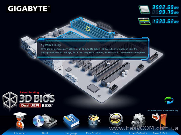
A. The 3D BIOS Screen (Default)
On GIGABYTE’s uniquely designed 3D BIOS screen, you can use your mouse to move through the motherboard image
and click to enter the function menu in each area for quick configuration. For example, pass your mouse arrow over the
CPU and memory sockets and enter the System Tuning menu to configure CPU/memory frequency, memory timings,
and voltage settings. For more detailed configuration items, you can click the function menu icons at the bottom of
the screen or press <F1> to switch to the main menu of the BIOS Setup program. (If a mouse is not connected, the
3D BIOS screen will automatically switch to the main menu of the BIOS Setup Program.)
B. The Main Menu of the BIOS Setup Program
On the main menu of the BIOS Setup program, press arrow keys to move among the items and press <Enter>
to accept or enter a sub-menu. Or you can use your mouse to select the item you want.
(Sample BIOS Version: F7b)
Setup Menus
Function Keys
Help
Enter Q-Flash
Select Default
Language
Configuration Items Current Settings
Switch to
3D BIOS
screen
Page: 33
BIOS Setup — 34 —
BIOS Setup Menus
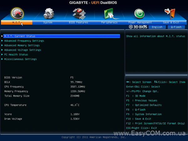
M.I.T.
Use this menu to configure the clock, frequency, and voltages of your CPU and memory, etc. Or check the
system/CPU temperatures, voltages, and fan speeds.
System
Use this menu to configure the default language used by the BIOS and system time and date. This menu
also displays information on the devices connected to the SATA ports.
BIOS Features
Use this menu to configure the device boot order, advanced features available on the CPU, and the primary
display adapter.
Peripherals
Use this menu to configure all peripheral devices, such as SATA, USB, integrated audio, and integrated
LAN, etc.
Power Management
Use this menu to configure all the power-saving functions.
Save & Exit
Save all the changes made in the BIOS Setup program to the CMOS and exit BIOS Setup. You can save the
current BIOS settings to a profile or load optimized defaults for optimal-performance system operations.
•
• When the system is not stable as usual, select the Load Optimized Defaults item to set your
system to its defaults.
•
• The BIOS Setup menus described in this chapter are for reference only and may differ by BIOS
version.
BIOS Setup Program Function Keys
<f><g> Move the selection bar to select a setup menu
<h><i> Move the selection bar to select an configuration item on a menu
<Enter> Execute command or enter a menu
<+>/<Page Up> Increase the numeric value or make changes
<->/<Page Down> Decrease the numeric value or make changes
<F1> Switch to 3D BIOS screen
<F5> Restore the previous BIOS settings for the current submenus
<F7> Load the Optimized BIOS default settings for the current submenus
<F8> Access the Q-Flash utility
<F9> Display system information
<F10> Save all the changes and exit the BIOS Setup program
<F12> Capture the current screen as an image and save it to your USB drive
<Esc> Main Menu: Exit the BIOS Setup program
Submenus: Exit current submenu
Page: 34
BIOS Setup
— 35 —
2-3 M.I.T.
Whether the system will work stably with the overclock/overvoltage settings you made is dependent
on your overall system configurations. Incorrectly doing overclock/overvoltage may result in damage
to CPU, chipset, or memory and reduce the useful life of these components. This page is for advanced
users only and we recommend you not to alter the default settings to prevent system instability or
other unexpected results. (Inadequately altering the settings may result in system’s failure to boot. If
this occurs, clear the CMOS values and reset the board to default values.)
This section provides information on the BIOS version, CPU base clock, CPU frequency, memory frequency,
total memory size , CPU temperature, Vcore, and memory voltage.
Page: 35
BIOS Setup — 36 —
`
` M.I.T. Current Status
This screen provides information on CPU/memory frequencies/parameters.
`
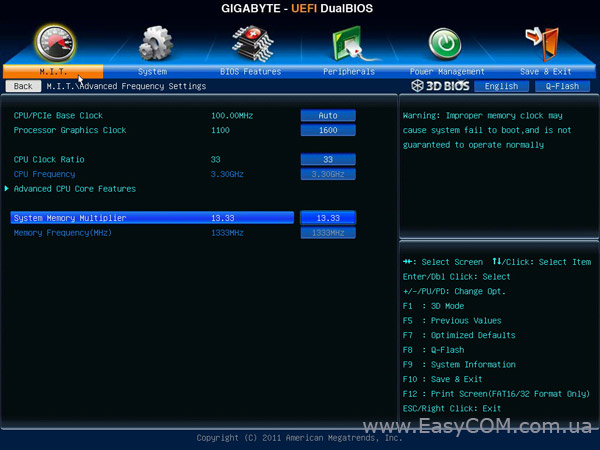
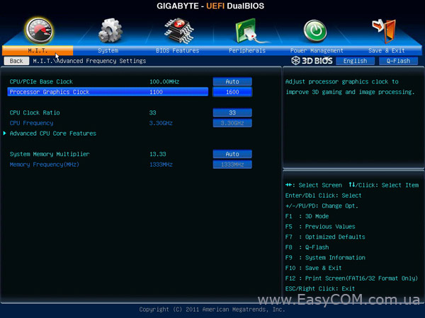
` Advanced Frequency Settings
&
& CPU/PCIe Base Clock
Allows you to manually set the CPU base clock and PCIe bus frequency in 0.01 MHz increments. (Default:
Auto)
Important: It is highly recommended that the CPU frequency be set in accordance with the CPU
specifications.
&
& Processor Graphics Clock
Allows you to set the onboard graphics clock. The adjustable range is from 400 MHz to 1600 MHz. (Default:
Auto)
&
& CPU Clock Ratio
Allows you to alter the clock ratio for the installed CPU. The adjustable range is dependent on the CPU
being installed.
&
& CPU Frequency
Displays the current operating CPU frequency.
Page: 36
BIOS Setup
— 37 —
(Note) This item is present only when you install a CPU that supports this feature. For more information about
Intel CPUs’ unique features, please visit Intel’s website.
&
& CPU Clock Ratio, CPU Frequency
The settings under the two items above are synchronous to those under the same items on the Advanced
Frequency Settings menu.
&
& Intel(R) Turbo Boost Technology (Note)
Allows you to determine whether to enable the Intel CPU Turbo Boost technology. Auto lets the BIOS
automatically configure this setting. (Default: Auto)
&
& Turbo Ratio (1-Core Active~4-Core Active) (Note)
Allows you to set the CPU Turbo ratios for different number of active cores. Auto sets the CPU Turbo ratios
according to the CPU specifications. (Default: Auto)
&
& Turbo Power Limit (Watts)
Allows you to set a power limit for CPU Turbo mode. When the CPU power consumption exceeds the
specified power limit, the CPU will automatically reduce the core frequency in order to reduce the power.
Auto sets the power limit according to the CPU specifications. (Default: Auto)
&
& Core Current Limit (Amps)
Allows you to set a current limit for CPU Turbo mode. When the CPU current exceeds the specified current
limit, the CPU will automatically reduce the core frequency in order to reduce the current. Auto sets the
power limit according to the CPU specifications. (Default: Auto)
&
& CPU Core Enabled (Note)
Allows you to determine whether to enable all CPU cores. Auto lets the BIOS automatically configure this
setting. (Default: Auto)
&
& Hyper-Threading Technology (Note)
Allows you to determine whether to enable multi-threading technology when using an Intel CPU that supports
this function. This feature only works for operating systems that support multi-processor mode. Auto lets
the BIOS automatically configure this setting. (Default: Auto)
`
` Advanced CPU Core Features
Page: 37
BIOS Setup — 38 —
&
& CPU Enhanced Halt (C1E) (Note 1)
Enables or disables Intel CPU Enhanced Halt (C1E) function, a CPU power-saving function in system
halt state. When enabled, the CPU core frequency and voltage will be reduced during system halt state to
decrease power consumption. Auto lets the BIOS automatically configure this setting. (Default: Auto)
&
& C3/C6 State Support (Note 1)
Allows you to determine whether to let the CPU enter C3/C6 mode in system halt state. When enabled, the
CPU core frequency and voltage will be reduced during system halt state to decrease power consumption.
The C3/C6 state is a more enhanced power-saving state than C1. Auto lets the BIOS automatically configure
this setting. (Default: Auto)
&
& CPU Thermal Monitor (Note 1)
Enables or disables Intel CPU Thermal Monitor function, a CPU overheating protection function. When
enabled, the CPU core frequency and voltage will be reduced when the CPU is overheated. Auto lets the
BIOS automatically configure this setting. (Default: Auto)
&
& CPU EIST Function (Note 1)
Enables or disables Enhanced Intel SpeedStep Technology (EIST). Depending on CPU loading, Intel EIST
technology can dynamically and effectively lower the CPU voltage and core frequency to decrease average
power consumption and heat production. Auto lets the BIOS automatically configure this setting. (Default:
Auto)
&
& Extreme Memory Profile (X.M.P.) (Note 2)
Allows the BIOS to read the SPD data on XMP memory module(s) to enhance memory performance when
enabled.
Disabled Disables this function. (Default)
Profile1 Uses Profile 1 settings.
Profile2 (Note 2)
Uses Profile 2 settings.
&
& System Memory Multiplier
Allows you to set the system memory multiplier. Auto sets memory multiplier according to memory SPD
data. (Default: Auto)
&
& Memory Frequency (MHz)
The first memory frequency value is the normal operating frequency of the memory being used; the second
is the memory frequency that is automatically adjusted according to the System Memory Multiplier
settings.
(Note 1) This item is present only when you install a CPU that supports this feature. For more information about
Intel CPUs’ unique features, please visit Intel’s website.
(Note 2) This item is present only when you install a CPU and a memory module that support this feature.
Page: 38
BIOS Setup
— 39 —
`
` Advanced Memory Settings
(Note) This item is present only when you install a CPU and a memory module that support this feature.
&
& Extreme Memory Profile (X.M.P.) (Note)
, System Memory Multiplier (SPD), Memory
Frequency(Mhz)
The settings under the three items above are synchronous to those under the same items on theAdvanced
Frequency Settings menu.
&
& Performance Enhance
Allows the system to operate at three different performance levels.
Normal Lets the system operate at its basic performance level.
Turbo Lets the system operate at its good performance level. (Default)
Extreme Lets the system operate at its best performance level.
&
& DRAM Timing Selectable
Quick and Expert allows the Channel Interleaving, Rank Interleaving, and memory timing settings below
to be configurable. Options are: Auto (default), Quick, Expert.
&
& Profile DDR Voltage
When using a non-XMP memory module or Extreme Memory Profile (X.M.P.) is set to Disabled, this item
will display as 1.50V. When Extreme Memory Profile (X.M.P.) is set to Profile1 or Profile2, this item will
display the value based on the SPD data on the XMP memory.
&
& Profile VTT Voltage
The value displayed here is dependent on the CPU being used.
&
& Channel Interleaving
Enables or disables memory channel interleaving. Enabled allows the system to simultaneously access
different channels of the memory to increase memory performance and stability. Auto lets the BIOS
automatically configure this setting. (Default: Auto)
&
& Rank Interleaving
Enables or disables memory rank interleaving. Enabled allows the system to simultaneously access different
ranks of the memory to increase memory performance and stability. Auto lets the BIOS automatically
configure this setting. (Default: Auto)
Page: 39
BIOS Setup — 40 —
This sub-menu provides memory timing settings for each channel of memory. The respective timing setting
screens are configurable only when DRAM Timing Selectable is set to Quick or Expert. Note: Your system
may become unstable or fail to boot after you make changes on the memory timings. If this occurs, please reset
the board to default values by loading optimized defaults or clearing the CMOS values.
`
` Channel A/B Timing Settings
`
` Advanced Voltage Settings
This sub-menu allows you to set CPU and memory voltages.
Page: 40
BIOS Setup
— 41 —
`
` PC Health Status
&
& Reset Case Open Status
Disabled Keeps or clears the record of previous chassis intrusion status. (Default)
Enabled
Clears the record of previous chassis intrusion status and the Case Open field will show
«No» at next boot.
&
& Case Open
Displays the detection status of the chassis intrusion detection device attached to the motherboard CI
header. If the system chassis cover is removed, this field will show «Yes», otherwise it will show «No». To
clear the chassis intrusion status record, set Reset Case Open Status to Enabled, save the settings to
the CMOS, and then restart your system.
Page: 41
BIOS Setup — 42 —
&
& CPU Vcore/Dram Voltage/+3.3V/+12V
Displays the current system voltages.
&
& CPU/System Temperature
Displays current CPU/system temperature.
&
& CPU/System FAN Speed
Displays current CPU/system fan speeds.
&
& CPU Warning Temperature
Sets the warning threshold for CPU temperature. When CPU temperature exceeds the threshold, BIOS will
emit warning sound. Options are: Disabled (default), 60o
C/140o
F, 70o
C/158o
F, 80o
C/176o
F, 90o
C/194o
F.
&
& CPU/System Fan Fail Warning
Allows the system to emit warning sound if the CPU fan or system fans are not connected or fail. Check
the fan condition or fan connection when this occurs. (Default: Disabled)
&
& CPU Fan Control mode
Auto
Lets the BIOS automatically detect the type of CPU fan installed and sets the optimal CPU
fan control mode. (Default)
Voltage Sets Voltage mode for a 3-pin CPU fan.
PWM Sets PWM mode for a 4-pin CPU fan.
Note: The Voltage mode can be set for a 3-pin CPU fan or a 4-pin CPU fan. However, for a 4-pin CPU
fan that is not designed following Intel PWM fan specifications, selecting PWM mode may not effectively
reduce the fan speed.
&
& CPU Fan Speed Control
Allows you to determine whether to enable the CPU fan speed control function and adjust the fan speed.
Normal
Allows the CPU fan to run at different speeds according to the CPU temperature. You can
adjust the fan speed with EasyTune based on your system requirements. (Default)
Silent Allows the CPU fan to run at slow speeds.
Manual Allows you to control the CPU fan speed under the Slope PWM item.
Disabled Allows the CPU fan to run at full speeds.
&
& Slope PWM
Allows you to control the CPU fan speed. This item is configurable only when CPU Fan Speed Control is
set to Manual. Options are: 0.75 PWM value /o
C ~ 2.50 PWM value /o
C.
&
& 1st/2nd/3rd System Fan Speed Control
Allows you to determine whether to enable the system fan speed control function and adjust the fan
speed.
Normal
Allows the system fan to run at different speeds according to the system temperature. You
can adjust the fan speed with EasyTune based on your system requirements. (Default)
Silent Allows the system fans to run at slow speeds.
Manual Allows you to control the system fan speed under the Slope PWM item.
Disabled Allows the system fans to run at full speeds.
&
& Slope PWM
Allows you to control the system fan speed. This item is configurable only when 1st/2nd/3rd System Fan
Speed Control is set to Manual. Options are: 0.75 PWM value /o
C ~ 2.50 PWM value /o
C.
Page: 42
BIOS Setup
— 43 —
`
` Miscellaneous Settings
&
& PEG — Gen X
Allows you to set the operation mode of the PCI Express slots to Gen 1, Gen 2, or Gen 3. Actual operation
mode is subject to the hardware specification of each slot. For example, the PCI Express x1 slots can
support up to Gen 2 mode only. Auto lets the BIOS automatically configure this setting. (Default: Auto)
Page: 43
BIOS Setup — 44 —
2-4 System
This section provides information on your CPU, memory, motherboard model, and BIOS version. You can also
select the default language used by the BIOS and manually set the system time.
&
& System Language
Selects the default language used by the BIOS.
&
& System Date
Sets the system date. The date format is week (read-only), month, date and year. Use <Enter> to switch
between the Month, Date, and Year fields and use the <Page Up> or <Page Down> key to set the desired
value.
&
& System Time
Sets the system time. The time format is hour, minute, and second. For example, 1 p.m. is 13:0:0. Use
<Enter> to switch between the Hour, Minute, and Second fields and use the <Page Up> or <Page Down>
key to set the desired value.
&
& Access Level
Displays the current access level depending on the type of password protection used. (If no password is
set, the default will display as Administrator.) The Administrator level allows you to make changes to all
BIOS settings; the User level only allows you to make changes to certain BIOS settings but not all.
`
` ATA Port Information
This section provides information on the device connected to each SATA port controlled by Intel Z77/H77
Chipset.You can enable/disable each SATA port or enable/disable the hot plug capability.
Page: 44
BIOS Setup
— 45 —
2-5 BIOS Features
&
& Boot Option Priorities
Specifies the overall boot order from the available devices. For example, you can set hard drive as the
first priority (Boot Option #1) and DVD ROM drive as the second priority (Boot Option #2). The list only
displays the device with the highest priority for a specific type. For example, only hard drive defined as the
first priority on the Hard Drive BBS Priorities submenu will be presented here.
Removable storage devices that support GPT format will be prefixed with «UEFI:» string on the boot device
list. To boot from an operating system that supports GPT partitioning, select the device prefixed with «UEFI:»
string.
Or if you want to install an operating system that supports GPT partitioning such as Windows 7 64-bit, select
the optical drive that contains the Windows 7 64-bit installation disk and is prefixed with «UEFI:» string.
&
& Hard Drive/CD/DVD ROM Drive/Floppy Drive/Network Device BBS Priorities
Specifies the boot order for a specific device type, such as hard drives, optical drives, floppy disk drives,
and devices that support Boot from LAN function, etc. Press <Enter> on this item to enter the submenu that
presents the devices of the same type that are connected. This item is present only if at least one device
for this type is installed.
&
& Bootup NumLock State
Enables or disables Numlock feature on the numeric keypad of the keyboard after the POST. (Default:
Enabled)
&
& Full Screen LOGO Show
Allows you to determine whether to display the GIGABYTE Logo at system startup. Disabled skips the
GIGABYTE Logo when the system starts up. (Default: Enabled)
&
& PCI ROM Priority
Allows you to determine which Option ROM to launch. Options are Legacy ROM and EFI Compatible ROM.
(Default: EFI Compatible ROM)
Page: 45
BIOS Setup — 46 —
&
& Limit CPUID Maximum(Note)
Allows you to determine whether to limit CPUID maximum value. Set this item to Disabled for Windows XP
operating system; set this item to Enabled for legacy operating system such as Windows NT4.0. (Default:
Disabled)
&
& Execute Disable Bit(Note)
Enables or disables Intel Execute Disable Bit function.This function may enhance protection for the computer,
reducing exposure to viruses and malicious buffer overflow attacks when working with its supporting software
and system. (Default: Enabled)
&
& Intel Virtualization Technology (Note)
Enables or disables Intel VirtualizationTechnology. Virtualization enhanced by Intel VirtualizationTechnology
will allow a platform to run multiple operating systems and applications in independent partitions. With
virtualization, one computer system can function as multiple virtual systems. (Default: Disabled)
&
& CSM Support
Enables or disables UEFI CSM (Compatibility Support Module) to support a legacy PC boot process.
Enabled allows you to boot from an operating system that requires traditional option ROM. Auto lets the
BIOS automatically configure this setting depending on the operating system being installed. (Default:
Enabled)
&
& Network stack
Disables or enables booting from the network to install a GPT format OS, such as installing the OS from
the Windows Deployment Services server. (Default: Disable Link)
&
& IPv4 PXE Support
Enables or disables IPv4 PXE Support. This item is configurable only when Network stack is enabled.
&
& IPv6 PXE Support
Enables or disables IPv6 PXE Support. This item is configurable only when Network stack is enabled.
(Note) This item is present only when you install a CPU that supports this feature. For more information about
Intel CPUs’ unique features, please visit Intel’s website.
&
& Administrator Password
Allows you to configure an administrator password. Press <Enter> on this item, type the password, and
then press <Enter>. You will be requested to confirm the password. Type the password again and press
<Enter>.You must enter the administrator password (or user password) at system startup and when entering
BIOS Setup. Differing from the user password, the administrator password allows you to make changes to
all BIOS settings.
&
& User Password
Allows you to configure a user password. Press <Enter> on this item, type the password, and then press
<Enter>. You will be requested to confirm the password. Type the password again and press <Enter>. You
must enter the administrator password (or user password) at system startup and when entering BIOS Setup.
However, the user password only allows you to make changes to certain BIOS settings but not all.
To cancel the password, press <Enter> on the password item and when requested for the password, enter the
correct one first. When prompted for a new password, press <Enter> without entering any password. Press
<Enter> again when prompted to confirm.
Page: 46
BIOS Setup
— 47 —
2-6 Peripherals
&
& LAN PXE Boot Option ROM
Allows you to decide whether to activate the boot ROM integrated with the onboard LAN chip. (Default:
Disabled)
&
& SATA Controller(s)
Enables or disables the integrated SATA controllers. (Default: Enabled)
Page: 47
BIOS Setup — 48 —
&
& SATA Mode Selection
Enables or disables RAID for the SATA controllers integrated in the Intel Z77/H77 Chipset or configures
the SATA controllers to AHCI mode.
IDE Configures the SATA controller to IDE mode. (Default)
RAID Enables RAID for the SATA controller.
AHCI
Configures the SATA controllers to AHCI mode. Advanced Host Controller Interface
(AHCI) is an interface specification that allows the storage driver to enable advanced
Serial ATA features such as Native Command Queuing and hot plug.
&
& xHCI Pre-Boot Driver
Enabled
The USB 3.0 ports are routed to the xHCI controller before booting to OS. (Default)
Disabled
The USB 3.0 ports are routed to the EHCI controller before booting to OS.
When this item is set to Enabled, the xHCI Mode below will be automatically set to Smart Auto; when this
item is set to Disabled, the xHCI Mode below will be automatically set to Auto.
&
& xHCI Mode
Allows you to determine the operating mode for the xHCI controller in OS.
Smart Auto This mode is available only when the BIOS supports the xHCI controller in the pre-boot
environment. This mode is similar to Auto, but it adds the capability to route the ports
to xHCI or EHCI according to setting used in previous boots (for non-G3 boot) in the
pre-boot environment. This allows the use of USB 3.0 devices prior to OS boot. xHCI
controller enabling and rerouting should follow the steps in Auto, when previous boot
routs ports to EHCI. Note: This is the recommended mode when BIOS has xHCI pre-
boot support. (Default)
Auto
BIOS routes the sharable ports to EHCI controller. Then it uses ACPI protocols to
provide an option to enable the xHCI controller and reroute the sharable ports. Note:
This is the recommended mode when BIOS does NOT have xHCI pre-boot support.
Enabled AllsharedportsareeventuallyroutedtothexHCIcontrollerduringtheBIOSbootprocess.
If BIOS does not have pre-boot support for the xHCI controller, it should initially route
the sharable ports to the EHCI controller and then prior to OS boot it should route the
ports to xHCI controller. Note: OS has to provide support for the xHCI controller in this
mode. If the OS does not provide support, all sharable ports won’t work.
Disabled
The USB 3.0 ports are routed to the EHCI controller and the xHCI controller is turned
off. All USB 3.0 devices function as High Speed devices regardless of xHCI software
support/availability. If this item is set to Disabled, the HS Port #1/2/3/4 Switchable
and xHCI Streams items below will become unconfigurable.
&
& HS Port #1 Switchable~HS Port #4 Switchable
Enabled
Corresponding USB 3.0 port is routed to xHCI. The USB 3.0 device attached on this
port with Super-Speed capability is visible to xHCI controller. (Default)
Disabled
Corresponding USB 3.0 port is routed to EHCI. The USB 3.0 device attached on this
port with Super-Speed capability will function as High-Speed.
Page: 48
BIOS Setup
— 49 —
&
& xHCI Streams
Enables or disables multi-stream data transfer. Note: For Windows 7 USB 3.0 Streams support, devices
may require UASP class driver updates from UASP driver vendors to be fully compatible with Intel USB
3.0 Streams Support. (Default: Enabled)
&
& USB2.0 Controller
Enables or disables the integrated USB 2.0/1.1 controller. (Default: Enabled)
&
& Audio Controller
Enables or disables the onboard audio function. (Default: Enabled)
If you wish to install a 3rd party add-in audio card instead of using the onboard audio, set this item to
Disabled.
&
& Init Display First
Specifes the frst initiation of the monitor display from the installed PCI graphics card, PCI Express graphics
card, or the onboard graphics.
Auto Lets BIOS automatically configure this setting. (Default)
IGFX Sets the onboard graphics as the first display.
PEG Sets the PCI Express graphics card on the PCIEX16 slot as the first display.
PCI Sets the graphics card on the PCI slot as the first display.
&
& Internal Graphics
Enables or disables the onboard graphics function. (Default: Auto)
&
& Internal Graphics Memory Size
Allows you to set the onboard graphics memory size. Options are: 32M~1024M. (Default: 64M)
&
& DVMT Total Memory Size
Allows you to allocate the DVMT memory size of the onboard graphics. Options are: 128M, 256M, MAX.
(Default: MAX)
&
& Intel(R) Rapid Start Technology
Enables or disables Intel Rapid Start Technology. This item is configurable only when an SSD is installed.
(Default: Disabled)
&
& Legacy USB Support
Allows USB keyboard/mouse to be used in MS-DOS. (Default: Enabled)
&
& XHCI Hand-off
Determines whether to enable XHCI Hand-off feature for an operating system without XHCI Hand-off
support. (Default: Enabled)
&
& EHCI Hand-off
Determines whether to enable EHCI Hand-off feature for an operating system without EHCI Hand-off
support. (Default: Disabled)
&
& Port 60/64 Emulation
Enables or disables emulation of I/O ports 64h and 60h. This should be enabled for full legacy support
for USB keyboards/mice in MS-DOS or in operating system that does not natively support USB devices.
(Default: Disabled)
&
& USB Storage Devices
Displays a list of connected USB mass storage devices. This item appears only when a USB storage
device is installed.
Page: 49
BIOS Setup — 50 —
`
` Trusted Computing
&
& TPM SUPPORT
Enables or disablesTrusted Platform Module (TPM). Set this item to Enable when aTPM device is installed.
(Default: Disable)
&
& OnBoard LAN Controller#1
Enables or disables the onboard LAN function. (Default: Enabled)
If you wish to install a 3rd party add-in network card instead of using the onboard LAN, set this item to
Disabled.
`
` Super IO Configuration
This section provides information on the super I/O chip and allows you to configure the serial port.
&
& Serial Port A
Enables or disables the onboard serial port. (Default: Enabled)
`
` Intel(R) Smart Connect Technology
&
& ISCT Configuration
Enables or disables Intel Smart Connect Technology. (Default: Disabled)
Page: 50
BIOS Setup
— 51 —
&
& AC BACK
Determines the state of the system after the return of power from an AC power loss.
Always Off
The system stays off upon the return of the AC power. (Default)
Always On The system is turned on upon the return of the AC power.
Memory
The system returns to its last known awake state upon the return of the AC
power.
&
& Power On By Keyboard
Allows the system to be turned on by a PS/2 keyboard wake-up event.
Note: To use this function, you need an ATX power supply providing at least 1A on the +5VSB lead.
Disabled Disables this function. (Default)
Any Key Press any key to turn on the system.
Keyboard 98 Press POWER button on the Windows 98 keyboard to turn on the system.
&
& Resume by Alarm
Determines whether to power on the system at a desired time. (Default: Disabled)
If enabled, set the date and time as following:
Wake up day: Turn on the system at a specific time on each day or on a specific day in a month.
Wake up hour/minute/second: Set the time at which the system will be powered on automatically.
Note: When using this function, avoid inadequate shutdown from the operating system or removal of the
AC power, or the settings may not be effective.
&
& ErP
Determines whether to let the system consume less than 1W power in S5 (shutdown) state. (Default:
Disabled)
Note: When this item is set to Enabled, the following functions will become unavailable: PME event wake
up, power on by mouse, power on by keyboard, and wake on LAN.
2-7 Power Management