Введение
Об этом руководстве……………………………..7
Словарь символов…………………………………7
Запасные части и аксессуары………………..7
Быстрый обзор
Быстрый обзор…………………………………….10
Безопасность детей
Детские сиденья………………………………….21
Установка детского сиденья…………………22
Дополнительные подушки…………………….23
Места расположения креплений
ISOFIX……………………………………………..24
Замки с функцией блокировки от
отпирания детьми…………………………….25
Защита людей, находящихся в
автомобиле
Принципы работы………………………………..26
Пристегивание ремней безопасности……30
Регулировка высоты крепления ремня
безопасности……………………………………31
Использование ремней безопасности во
время беременности………………………..31
Дуги защиты при опрокидывании………….32
Отключение подушки безопасности
пассажира………………………………………..32
Ключи и пульты дистанци-
онного управления
Общая информация о радиочастотах…..34
Программирование пульта
дистанционного управления……………..34
Замена элемента питания пульта
дистанционного управления……………..36
Замки
Блокировка и разблокировка замков…….39
Система управления замками без помощи
ключа……………………………………………….43
Полное открывание/ закрывание………….48
Иммобилайзер двигателя
Принципы работы………………………………..51
Запрограммированные ключи………………51
Активация иммобилайзера
двигателя…………………………………………51
Отключение иммобилайзера
двигателя…………………………………………51
Сигнализация
Активация сигнализации………………………52
Отключение сигнализации……………………53
Рулевое колесо
Регулировка положения рулевого
колеса……………………………………………..55
Звуковой сигнал…………………………………..55
Управление аудиосистемой………………….55
Голосовое управление…………………………57
Педали
Регулировка положения педалей………….58
Стеклоочистители и стеклоомы-
ватели
Очистители ветрового стекла……………….59
Омыватели ветрового стекла……………….61
Очиститель и омыватели заднего
стекла………………………………………………61
Регулировка положения жиклеров
омывателей стекол…………………………..62
Омыватели фар…………………………………..62
Проверка щеток стеклоочистителей……..63
Замена щеток стеклоочистителей…………63
Осветительное оборудование
Органы управления осветительным
оборудованием…………………………………64
Адаптивное освещение………………………..65
Передние противотуманные фары……….65
1
Содержание

Introduction 4
Instrument Cluster 10
Warning and control lights 10
Gauges 14
Entertainment Systems 16
AM/FM stereo with single CD 16
AM/FM stereo with in-dash six CD 20
Remote audio controls 24
Climate Controls 26
Heater only 26
Manual heating and air conditioning 27
Rear window defroster 29
Lights 30
Headlamps 30
Turn signal control 32
Driver Controls 40
Windshield wiper/washer control 40
Steering wheel adjustment 41
Power windows 44
Mirrors 45
Speed control 45
Locks and Security 53
Keys 53
Locks 53
Anti-theft system 55
Table of Contents
1
2005 Focus (foc)
Owners Guide (post-2002-fmt)
USA English (fus)
Table of Contents
- Руководства по ремонту
- Руководство по ремонту и эксплуатации Форд Фокус 1998-2005 г.в.
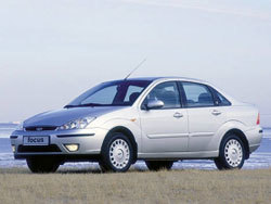
Руководство по ремонту и эксплуатации Ford Focus / Форд Фокус
Общая информация об автомобиле.
Модель Focus является новинкой в модельном ряду Ford. Автомобиль имеет дизайн нового поколения.
Ford Focus (Форд Фокус) – хороший выбор при покупке автомобиля, так как ремонт для него редкость. Он имеет прекрасные отзывы профессиональных экспертов, отличные результаты тестовых испытаний ведущих европейских журналов. В настоящее время Focus выпускается в четырех кузовных вариантах: 3- или 5-дверный хэтчбек, 4-дверный седан и 5-дверный универсал Turnier. Focus имеет три комплектации Ambientе, Trend и Ghia. На выбор предлагается шесть вариантов двигателей.Ремонт Форд Фокусосуществляется в ольшинстве случаев своими руками при помощи инструкций и советов профессионалов.
На автомобиле, в дополнение к насыщенному перечню автомобильных опций, устанавливается система курсовой устойчивости ESP. Электроника обрабатывает примерно 150 сигналов в секунду и согласует фактическое поведение автомобиля с действиями водителя. При потере курсовой устойчивости система автоматически подтормаживает одно или несколько колес или при необходимости изменяет мощность двигателя в соответствии с дорожными условиями.
По желанию покупателя, компания Ford оснащает системой ЕSP двигатели Zetec объемом от 1,6 до 2 л. Двигатели 1,8 и 2,0 л могут дополнительно оснащаться противобуксовочной системой ASR.
Для комфортной поездки лучше всего вам подойдет Ambientе. Он имеет те же опции, что и Focus Trend. Focus Ambientе поставляется исключительно с пятью дверьми. Модель комплектуют бензиновыми двигателями 1,4 л Zetec-SE мощностью 55 кВт (75 л.с.), 1,8 л Zetec-E мощностью 85 кВт (115 л.с.) и двумя новыми турбодизелями с объемом 1,8 л, мощностью 55 кВт (75 л.с.) или 66 кВт (90 л.с.). Внешне комплектация Ambientе отличается от Trend по табличке.
Комплектация Trend в настоящее время наиболее покупаемая. Кроме серийных опций, исключительно для спортивной езды, покупатели Trend могут получить два специальных «тренд пакета»: Trend 1 включает легкосплавные диски 6Jх15″ и шины 195, противотуманные фары, регулируемое освещение салона и подголовники для задних сидений, Trend 2 предусматривает установку легкосплавных дисков 6jх16″ и шины 205/50 R16.
Ghia можно отнести к высшему классу. Focus Ghia отличает от Ambientе наличие климат-контроля, покрашенных под цвет автомобиля, подогреваемых боковых зеркал с электроприводом, хромированных дверных ручек, панели приборов двух цветов. Внешне Ghia можно отличить по табличке, хромированному молдингу на переднем бампере, типичным для Ghia декоративным колесным колпакам, хромированной ручке багажника и при открытых дверях накладкам на пороги с эмблемой Ghia.
Универсал Turnier кроме базовой комплектации с объемом 1,4 л оснащается всем набором опций, всеми имеющимися вариантами трансмиссии, включая автоматическую коробку. Исключение Blitz-Turnier с двигателем Zetec-E объемом 2,0 л, с опциями Focus Ambientе, заслуживающий внимания из-за его подходящей стоимости.
Ремонт Ford Focus сам по себе возможен как своими руками, так и в специализированных мастерских. Для тех, кто предпочитает все выполнять самостоятельно предназначен наш сайт. На нем вы можете найти большое количество руководств для ремонта онлайн в электронном виде. Сайт одинаково хорошо работает как на мобильных устройствах, так и на стационарных компьютерах. Полный перечень разделов и агрегатов вы найдете под этой статьей.
↓ Комментарии ↓
1. Введение
1.0 Общие сведения о ремонте
1.1 Выбор дополнительных опций
1.2 Как пользоваться данным руководством по ремонту
1.3. Рабочее место для ремонта
1.4. Рекомендации по посещению мастерской
1.5 Безопасность — главное при ремонте
1.6. Инструмент
1.7 Советы профессионалов при работе с резьбовым соединением
1.8. Подъем автомобиля с помощью домкрата
1.9. Периодическое обслуживание и уход за автомобилем
1.10. Модельный ряд автомобилей Ford Focus
2. Двигатели
2.0 Двигатели
2.1. Основные элементы конструкции двигателя
2.2. Варианты двигателей Ford Focus
2.3. Разборка двигателя
2.4. Установка силового агрегата
2.5. Сборка и разборка двигателя
2.6. Основные проверки деталей и узлов двигателя
2.7. Замер компрессии
3. Система смазки двигателя
3.0 Система смазки двигателя
3.1 Общие сведения о системе смазки двигателей
3.2 Циркуляция масла под давлением
3.3 Контрольная лампа аварийного давления масла
3.4. Моторное масло
3.5 Проверка уровеня масла
3.6 Замена масла
4. Система охлаждения
4.0 Описание системы охлаждения
4.1. Данные
4.2 Детали системы охлаждения
4.3 Охлаждающая жидкость
4.4 Проверка системы охлаждения на герметичность
4.5 Проверка уровня охлаждающей жидкости
4.6 Замена антифриза
4.7 Сборка и разборка вентилятора охлаждения
4.8 Снятие, установка и замена радиатора
4.9 Замена шлангов системы охлаждения
4.10. Водяной насос
4.11. Термостат
5. Система питания
5.0 Система питания
5.1 Система вентиляции
5.2 Основные компоненты системы питания
5.3 Осторожное обращение с топливом
5.4 Проверка вентиляции бака
5.5 Замена топливного фильтра
5.6 Дизельное топливо и конденсат
5.7 Снятие трубопроводов и шлангов
5.8 Поиск неисправностей топливного насоса
5.9 Снятие и установка топливного насоса на автомобиле с бензиновым двигателем
5.11. Воздушный фильтр
6. Управление силовым агрегатом и отработавшими газами
6.0 Система впрыска
6.1. Блок управления EEC-V впрыском
6.2. Самостоятельная работа с системой впрыска может быть ограничена
6.3. Система питания дизеля — базовая конструкция
6.4 Ротор датчика управляющих импульсов и датчик угла поворота
6.5 Устройство холодного пуска
6.6 Форсунки
6.7. Ремонт и корректировка системы впрыска дизеля — случай для экспертов
7. Система зажигания
7.0 Система зажигания
7.1. Общие сведения
7.2 Катушка зажигания
7.3. Свечи зажигания
7.4. Работа с системой зажигания
8. Сцепление
8.0 Сцепление
8.1 Детали сцепления
8.2 Привод сцепления
8.3. Работа сцепления
8.4 Неполное выключение сцепления
8.5 Движение автомобиля с постоянно включенным сцеплением
8.6 Замена сцепления в случае, когда на автомобиле установлена коробка передач iB5
8.7 Главный цилиндр сцепления
9. Коробка передач
9.0 Коробка передач
9.1 Установка механизма управления коробки передач iB5
9.2 Регулировка механизма управления коробки передач MTX-75
9.3 Регулировка механизма управления автоматической коробки передач 4F27E
9.4 Механическая разблокировка селектора автоматической коробки передач 4F27E
9.5. Проверка уровня масла в коробке передач
9.6 Снятие и установка коробки передач iB5
9.7 Снятие и установка коробки передач МТХ-75
10. Привод передних колес
10.0 Привод передних колес
10.1 Проверка грязезащитных чехлов привода колес
10.2. Снятие привода передних колес
10.3. Замена грязезащитных чехлов привода передних колес
11. Неисправности передней подвески
11.0 Передняя подвеска
11.1. Углы установки колес
11.2 Детали и узлы передней подвески
11.3. Замена кулака
11.4. Замена рычага
11.5. Амортизаторная стойка
11.6. Разборка и сборка амортизаторной стойки
11.7 Углы установки передних колес
12. Задняя подвеска
12.0 Задняя подвеска
12.1 Ремонт задней подвески
12.2. Поперечная балка
12.3. Ступица колеса
12.4. Подшипник ступицы колеса
12.5. Поперечный рычаг нижний (передний)
12.6. Поперечный рычаг нижний (задний)
12.7. Верхний поперечный рычаг
12.8. Стабилизатор поперечной устойчивости
12.9. Продольный рычаг
12.10. Поворотный кулак
12.11 Амортизатор
12.12. Пружина
13. Рулевое управление
13.0 Рулевое управление
13.1 Техническое состояние рулевого управления и передней подвески
13.2 Проверка зазоров в рулевом управлении
13.3 Проверка защитных чехлов зубчатой рейки
13.4 Проверка наконечников рулевых тяг и грязезащитных чехлов
13.5 Замена наконечников рулевых тяг
13.6 Замена грязезащитных чехлов рулевого механизма
13.7 Разборка и сборка рулевого механизма
13.8 Удаление воздуха из гидравлической системы гидроусилителя рулевого управления
13.9 Замена насоса гидроусилителя рулевого управления
14. Тормозная система
14.0 Тормозная система
14.1 Проверка уровня тормозной жидкости
14.2 Проверка состояния тормозной системы
14.3 Проверка вакуумного усилителя тормозов
14.4. Проверка работоспособности тормозов
14.5 Удаление воздуха из тормозной системы
14.6 Замена тормозной жидкости
14.7 Замена питающего бачка с главного тормозного цилиндра
14.8. Главный тормозной цилиндр
14.9. Вакуумный усилитель тормозов
14.11. Замена тормозных накладок
14.12. Снятие и установка тормозных дисков
14.13. Тормозная скоба и поршни тормозных цилиндров
14.14. Ступица заднего колеса
14.15. Стояночный тормоз
15. Электрооборудование
15.0 Электрооборудование
15.1. Основные понятия
15.2. Аккумуляторная батарея
15.3 Ремонт стартера
15.4. Генератор
15.5. Ремень привода вспомогательных агрегатов
15.6 Снятие стартера
15.7. Электродвигатель стеклоочистителя ветрового стекла
15.8 Электродвигатель стеклоочистителя заднего стекла
15.9. Наружное освещение
16. Система выпуска отработавших газов
16.0 Система выпуска отработавших газов
16.1. Отработавшие газы
16.2 Практические советы для работы с системой выпуска отработавших газов
16.3 Проверка системы выпуска отработавших газов
16.4. Замена системы выпуска отработавших газов
17. Колеса и шины
17.0 Колеса и шины
17.1. Колеса и шины
17.2. Замена колес
18. Приложение
18.0 Приложение
18.1. Моменты затяжки узлов и деталей автомобиля, Н·м
19. Схемы электрических соединений
19.0 Схемы электрических соединений
19.1 Построение схем электрических соединений
19.2. Предохранители и реле
19.3 Условные обозначения к электрическим схемам
19.4. Схемы
- Page 1
Table of Contents Introduction Instrument Cluster Warning and control lights Gauges Entertainment Systems AM/FM stereo with single CD AM/FM stereo with in-dash six CD Remote audio controls Climate Controls Heater only Manual heating and air conditioning Rear window defroster Lights Headlamps Turn signal control Driver Controls… -
Page 2: Table Of Contents
Table of Contents Seating and Safety Restraints Seating Safety restraints Airbags Child restraints Tires, Wheels and Loading Tire Information Tire Inflation Changing tires Lug Nut Torque Vehicle loading Trailer towing Recreational towing Driving Starting Brakes Traction control Transmission operation Roadside Emergencies Getting roadside assistance Hazard flasher switch Fuel pump shut-off switch…
-
Page 3: Table Of Contents
Ford Motor Company. Ford may change the contents without notice and without incurring obligation. Copyright © 2005 Ford Motor Company…
-
Page 4: Introduction
State of California to cause cancer and birth defects or other reproductive harm. CONGRATULATIONS Congratulations on acquiring your new Ford. Please take the time to get well acquainted with your vehicle by reading this handbook. The more you know and understand about your vehicle, the greater the safety and pleasure you will derive from driving it.
- Page 5
Introduction SAFETY AND ENVIRONMENT PROTECTION Warning symbols in this guide How can you reduce the risk of personal injury to yourself or others? In this guide, answers to such questions are contained in comments highlighted by the warning triangle symbol. These comments should be read and observed. - Page 6
In order to properly diagnose and service your vehicle, Ford Motor Company, Ford of Canada, and service and repair facilities may access vehicle diagnostic information through a direct connection to your vehicle when diagnosing or servicing your vehicle. - Page 7
• where the driver was positioning the steering wheel. To access this information, special equipment must be directly connected to the recording modules. Ford Motor Company and Ford of Canada do not access event data recorder information without obtaining consent,… - Page 8
Introduction These are some of the symbols you may see on your vehicle. Vehicle Symbol Glossary Safety Alert See Owner’s Guide Fasten Safety Belt Air Bag-Front Air Bag-Side Child Seat Child Seat Installation Child Seat Lower Warning Anchor Child Seat Tether Brake System Anchor Brake Fluid -… - Page 9
Introduction Vehicle Symbol Glossary Power Windows Power Window Lockout Front/Rear Interior Luggage Child Safety Door Compartment Release Lock/Unlock Symbol Panic Alarm Engine Oil Engine Coolant Engine Coolant Temperature Do Not Open When Hot Battery Avoid Smoking, Flames, Battery Acid or Sparks Explosive Gas Fan Warning Maintain Correct Fluid… -
Page 10: Instrument Cluster
Instrument Cluster WARNING LIGHTS AND CHIMES Standard instrument cluster Optional instrument cluster Warning lights and gauges can alert you to a vehicle condition that may become serious enough to cause expensive repairs. A warning light may illuminate when a problem exists with one of your vehicle’s functions. Many lights will illuminate when you start your vehicle to make sure the bulb works.
- Page 11
Instrument Cluster converter. Drive in a moderate fashion (avoid heavy acceleration and deceleration) and have your vehicle serviced immediately by your authorized dealer. Under engine misfire conditions, excessive exhaust temperatures could damage the catalytic converter, the fuel system, interior floor coverings or other vehicle components, possibly causing a fire. Check fuel cap: Illuminates when CHECK the fuel cap may not be properly… - Page 12
Instrument Cluster Airbag readiness: If this light fails to illuminate when ignition is turned to ON, continues to flash or remains on, have the system serviced immediately by your authorized dealer. A chime will also sound when a malfunction in the supplemental restraint system has been detected. Safety belt: Reminds you to fasten your safety belt. - Page 13
Instrument Cluster Traction Control system (if equipped): Illuminates when the Traction Control is turned OFF and will flash when active. If the light remains on, have the system serviced immediately, refer to the Driving chapter for more information. Low fuel: Illuminates when the fuel level in the fuel tank is at or near empty (refer to Fuel gauge in this chapter). -
Page 14: Gauges
Instrument Cluster GAUGES Speedometer: Indicates the current vehicle speed. Engine coolant temperature gauge: Indicates engine coolant temperature. At normal operating temperature, the needle will be in the normal range. If it enters the red section, the engine is overheating. Stop the vehicle as soon as safely possible, switch off the engine and let the engine cool.
- Page 15
Instrument Cluster Odometer: Registers the total miles (kilometers) of the vehicle. Trip odometer: Registers the miles (kilometers) of individual journeys. To reset, depress the reset control. Tachometer (if equipped): Indicates the engine speed in revolutions per minute. Driving with your tachometer pointer continuously at the top of the scale may damage the engine. -
Page 16: Entertainment Systems
Entertainment Systems AM/FM STEREO WITH SINGLE CD — PREMIUM (IF EQUIPPED) AM/FM STEREO WITH SINGLE CD/MP3 — PREMIUM (IF EQUIPPED) 2005 Focus (foc) Owners Guide (post-2002-fmt) USA (fus)
- Page 17
Entertainment Systems Tune selector: Press to manually increase/decrease the radio frequency. 2. Phone/mute: Press to mute the playing media. Press again to return to the playing media. 3. Menu: Press MENU to access the main menu functions. Use the Tune selector ( ) or SEEK… - Page 18
Entertainment Systems selector ( ) or SEEK to turn off or select rates 1 through 7. Rate 7 compensates the most volume at higher speeds. Setting the clock: Upon initial battery connect, this function is displayed first among MENU functions. Once the clock is set, this will be shown as the last MENU function. - Page 19
Entertainment Systems 11. Rewind: Press and hold to manually reverse the CD. 12. Memory presets: To set a station: Select frequency band AM/FM1/FM2; tune to a desired station, press and hold the preset button until the display shows that the preset is set. - Page 20
Entertainment Systems AM/FM STEREO WITH IN–DASH 6CD —PREMIUM /AUDIOPHILE (IF EQUIPPED) Tune Selector: Press to manually increase/decrease the radio frequency when in tuner mode or to choose a different disc when in CD mode with multiple discs in the changer. 2. - Page 21
Entertainment Systems To activate RDS, press and hold MENU until RDS ON or RDS OFF appears in the display. Press MENU again to continue to FIND and SHOW functions. Press the Tune Selector ( ) or SEEK toggle RDS on/off and to scroll through the FIND and SHOW functions. Track/Folder mode:Available only on MP3 discs in CD mode. - Page 22
Entertainment Systems 5. Seek up: Press for next strong station or CD track. Press and hold for continuous seek functionality. 6. Text: Press in CD mode to display track title, artist and album title. This feature will only function if the CDs are manufactured with the CD text feature. 7. - Page 23
Entertainment Systems 16. ON/OFF/Volume: Press to turn ON/OFF; turn to increase/decrease the volume levels. If the volume is set above a certain level and the ignition is turned off, for at least a minute, the volume will come back on at a “nominal” listening level when the ignition switch is turned back 17. - Page 24
Entertainment Systems REMOTE AUDIO STEERING COLUMN CONTROLS (IF EQUIPPED) The remote audio steering column controls may be used to select radio or CD mode. The following functions can be carried out using the remote control. • Volume: Pull VOL+ towards the steering wheel to increase the volume. - Page 25
Due to technical incompatibility, certain recordable and re-recordable compact discs may not function correctly when used in Ford CD players. Irregular shaped CDs, CDs with a scratch protection film attached, and CDs with homemade paper (adhesive) labels should not be inserted into the CD player. -
Page 26: Climate Controls
Climate Controls HEATER ONLY SYSTEM (IF EQUIPPED) 1. Air flow selections: Controls the direction of the airflow in the cabin. See the following for a brief description on each control. : Distributes air through the instrument panel vents. : Distributes air through the instrument panel vents and the floor vents.
-
Page 27: Manual Heating And Air Conditioning
Climate Controls 2. Adjust the temperature control to maintain comfort. 3. Set the fan speed to the highest setting. 4. Direct the outer instrument panel vents toward the side windows. To increase airflow to the outer instrument panel vents, close the vents located in the middle of the instrument panel.
- Page 28
Climate Controls 5. A/C: Provides cabin cooling. 6. Temperature selection: Controls the temperature of the airflow in the cabin. Max A/C: For maximum cabin cooling performance, select A/C (5) (4). Operating tips • To reduce fog build up on the windshield during humid weather, place the air flow selector in the position and turn the fan on. -
Page 29: Rear Window Defroster
Climate Controls REAR WINDOW DEFROSTER The rear defroster control is located on the instrument panel. Press the rear defroster control to clear the rear window of thin ice and fog. • A small LED will illuminate when the rear defroster is activated. The ignition must be in the ON position to operate the rear window defroster.
-
Page 30: Lights
Lights HEADLAMP CONTROL Turns the lamps off. Turns on the parking lamps, instrument panel lamps, license plate lamps and tail lamps. Turns the headlamps on. Foglamp control (if equipped) The headlamp control also operates the foglamps. The foglamps can be turned on when the headlamp control is in the position and…
- Page 31
Lights High beams Pull the lever towards you to activate. Pull the lever towards you again to deactivate. Flash to pass Pull toward you slightly to activate and release to deactivate. PANEL DIMMER CONTROL Use to adjust the brightness of the instrument panel during headlight and parklamp operation. -
Page 32: Turn Signal Control
Lights 3. Turn on the low beam headlamps to illuminate the wall or screen and open the hood. 4. On the wall or screen you will observe an area of high intensity light. The top of the high intensity area should touch the horizontal reference line.
- Page 33
Lights INTERIOR LAMPS Dome lamps The dome lamp is equipped with a control switch that will illuminate when: • the doors are closed and the switch is in the on position. • the switch is in the door activated position and any door is open. When the dome lamp switch is in the off position, it will not illuminate when you open the doors. - Page 34
Lights Function Trade number Headlamps Park and turn lamp (front) 3157AK or 3157A Side marker lamp (front) GE194 Foglamps (if equipped) Stop/turn and tail lamps (wagon) 3157K Stop/turn and tail lamps (sedan) 3157K or 4157K Stop/turn and tail lamps (3-door/5-door) 3057K or 4057K Backup lamp (sedan/wagon) 3156K or 3156… - Page 35
Lights Replacing front parking lamp/turn signal bulbs 1. Make sure the headlamp control is in the OFF position and open the hood. 2. Remove the bulb socket from the lamp assembly by turning counterclockwise. 3. Pull the bulb straight out of the socket. - Page 36
Lights Replacing tail/brake/backup lights and turn signal bulbs (sedan) 1. Make sure the headlamp control is in the OFF position and then open the trunk. 2. From inside the luggage compartment remove the three wing nuts of the light housing. 3. - Page 37
Lights Replacing side marker bulbs 1. Make sure the headlamp control is in the OFF position. 2. Reach under the front fender, grasp the bulb socket and turn it counterclockwise to remove it. 3. Pull the bulb straight out. Install in reverse order. Replacing high-mount brake lamp bulbs Sedan 1. - Page 38
Lights 1. Make sure the headlamp control is in the OFF position. 2. Remove the screws using a Torx T20 screwdriver and then remove the plastic cover. 3. Unclip the bulb holder from the reflector. 4. Pull the bulb straight out. Install in reverse order. - Page 39
Lights Replacing interior lamps 1. Make sure the headlamp switch is in the OFF position. 2. Switch off the interior lamps. 3. Pry out the light assembly with a flat screwdriver at the side opposite the switch. Install in reverse order. Replacing reading bulbs 1. -
Page 40: Driver Controls
Driver Controls MULTI-FUNCTION LEVER Windshield wiper: Move the lever down for a single wipe. For intermittent operation, move control up one position and adjust the rotary control to the desired speed. For normal operation, move control up two positions. For high speed operation, move control up three positions. Mist function: To mist, push and release the windshield washer control quickly.
- Page 41
Driver Controls Changing the wiper blades 1. Pull the wiper arm away from the vehicle. Turn the blade at an angle from the wiper arm. Push the lock pin manually to release the blade and pull the wiper blade down toward the windshield to remove it from the arm. - Page 42
Driver Controls HORN Press the steering wheel pad. The horn can be operated when the ignition is off. OVERHEAD CONSOLE (IF EQUIPPED) The appearance of your vehicle’s overhead console will vary according to your option package. Storage compartment Press the latch to open the storage compartment. - Page 43
Driver Controls • Place the VELCRO hook onto the side of the aftermarket transmitter opposite of the button. • Place the transmitter into storage compartment, button down. • Place the provided height adaptors onto the back of the door as needed. •… -
Page 44: Power Windows
Driver Controls Cigar lighter (if equipped) Do not plug optional electrical accessories into the cigarette lighter socket. Do not hold the lighter in with your hand while it is heating, this will damage the lighter element and socket. The lighter will be released from its heating position when it is ready to be used.
-
Page 45: Mirrors
Driver Controls MIRRORS Power side view mirrors (if equipped) To adjust your mirrors: 1. Rotate the control clockwise to adjust the right mirror and rotate the control counterclockwise to adjust the left mirror. 2. Move the control in the direction you wish to tilt the mirror.
- Page 46
Driver Controls Setting speed control The controls for using your speed control are located on the steering wheel for your convenience. 1. Press the ON control and release 2. Accelerate to the desired speed. 3. Press the SET ACCEL control and release it. - Page 47
Driver Controls Resuming a set speed Press the RES (resume) control and release it. This will automatically return the vehicle to the previously set speed. The RES control will not work if the vehicle speed is not faster than 30 mph (48 km/h). Increasing speed while using speed control There are two ways to set a higher speed:… - Page 48
Driver Controls • Depress the brake pedal until the desired vehicle speed is reached, press the SET ACCEL control. Turning off speed control Press the speed control OFF control. Note: When you turn off the speed control or the ignition, your speed control set speed memory is erased. - Page 49
The moon roof will move about 0.5 seconds at a time and then stop again. Press the switch repeatedly until the moon roof is closed. Have the system checked by your Ford Dealer immediately. REMOTE LUGGAGE COMPARTMENT RELEASE (IF EQUIPPED) - Page 50
Driver Controls CELL PHONE USE The use of Mobile Communications Equipment has become increasingly important in the conduct of business and personal affairs. However, drivers must not compromise their own or others’ safety when using such equipment. Mobile Communications can enhance personal safety and security when appropriately used, particularly in emergency situations. - Page 51
Driver Controls Wagon Pull out the roller cover and secure the retaining points. The cover can be removed completely by pressing inward on both ends of the support. To reduce the risk of injury, the luggage cover must be properly attached to the mounting clips. - Page 52
Driver Controls Make sure that the liftgate door is closed to prevent exhaust fumes from being drawn into the vehicle. This will also prevent passengers and cargo from falling out. If you must drive with the liftgate door open, keep the vents open so outside air comes into the vehicle LUGGAGE RACK (IF EQUIPPED) The maximum recommended load is… -
Page 53: Locks And Security
Locks and Security KEYS The key operates all locks on your vehicle. You should always carry a second key with you in a safe place in case you require it in an emergency. Your keys are coded to your vehicle; using a non-coded key will not permit your vehicle to start.
- Page 54
Locks and Security To deactivate/reactivate the autolock feature using the power door unlock control You must complete steps 1-7 within 30 seconds or the procedure will have to be repeated. If the procedure needs to be repeated, you must wait 30 seconds. 1. - Page 55
Locks and Security Childproof door locks (if equipped) • When these locks are set, the rear doors cannot be opened from the inside. • The rear doors can be opened from the outside when the doors are unlocked. The childproof locks are located on rear edge of each rear door and must be set separately for each door. - Page 56
Locks and Security To open the luggage compartment door (lid) from within the luggage compartment, pull the illuminated “T” shaped handle and push up on the trunk lid. The handle is composed of a material that will glow for hours in darkness following brief exposure to ambient light. - Page 57
Locks and Security REMOTE ENTRY SYSTEM (IF EQUIPPED) This device complies with part 15 of the FCC rules and with RS-210 of Industry Canada. Operation is subject to the following two conditions: (1) This device may not cause harmful interference, and (2) This device must accept any interference received, including interference that may cause undesired operation. - Page 58
Locks and Security Unlocking the doors 1. Press and release to unlock the driver’s door. Note: The interior lamps will illuminate. 2. With the all-door remote entry, press and release again within three seconds to unlock all the doors. The remote entry system activates the illuminated entry feature. This feature turns on the interior lamps for 25 seconds or until the ignition is turned to the 3 (ON) position. - Page 59
Locks and Security Opening the luggage compartment Press once to open the luggage compartment. Note: This feature will only operate with the ignition in the 1 (LOCK) or the 2 (OFF) position. • Ensure that the trunk is closed and latched before driving your vehicle. - Page 60
Locks and Security 4. Insert the new battery. Refer to the diagram inside the remote entry transmitter for the correct orientation of the battery. Press the battery down to ensure that the battery is fully seated in the battery housing cavity. -
Page 61: Anti-Theft System
Note: The SecuriLock passive anti-theft system is not compatible with non-Ford aftermarket remote start systems. Use of these systems may result in vehicle starting problems and a loss of security protection. Note: Large metallic objects, electronic devices that are used to purchase gasoline or similar items, or a second coded key on the same key chain may cause vehicle starting issues.
- Page 62
Locks and Security Replacing coded keys can be very costly. Store an extra programmed key away from the vehicle in a safe place to help prevent any inconveniences. Please visit an authorized dealer to purchase additional spare or replacement keys. Programming spare keys You can program your own coded keys to your vehicle. - Page 63
Locks and Security 10. Turn the ignition from the 2 (OFF) position to the 3 (ON) position. Keep the ignition in the 3 (ON) position for at least one second, but no more than 10 seconds. 11. Your new, unprogrammed key is now programmed. If the key has been successfully programmed it will start the vehicle’s engine and the theft indicator light will illuminate for three seconds and then go out. -
Page 64: Seating And Safety Restraints
Seating and Safety Restraints SEATING Notes: Reclining the seatback can cause an occupant to slide under the seat’s safety belt, resulting in severe personal injuries in the event of a collision. Do not pile cargo higher than the seatbacks to reduce the risk of injury in a collision or sudden stop.
- Page 65
Seating and Safety Restraints Adjusting the front manual seat Pull the lever located under the front edge of the seat to move the seat forward or backward. Turn the handle to adjust the height of the seat. Lift the control to adjust the angle of the seatback. - Page 66
Seating and Safety Restraints To operate the heated seats: • Push control to activate. • Push again to deactivate. The heating will operate when the ignition switch is in position 2. The indicator light on the switch is illuminated when activated. Although the indicator light is illuminated, the heat is regulated by a thermostat which causes the heat to activate within a certain range. - Page 67
Seating and Safety Restraints Do not place objects behind the seat which could prevent the engagement of the seat lock. REAR SEATS Folding rear seat cushion forward Lift the seat cushion and pull it forward. Before returning the seatback to its original position, make sure that cargo or any objects are not trapped behind the seatback. - Page 68
Seating and Safety Restraints Sedan Remove the head restraints (if equipped) of the rear seats and stow them on the floor behind the front seats. Pull one or both of the unlocking controls in the luggage compartment and fold the rear seatback forward. Returning the seatback to the upright position Fold back the seatback until it locks with a distinct “click.”… -
Page 69: Safety Restraints
Seating and Safety Restraints Folding the seat cushion and seatback forward Fold the seat cushion forward. Remove the head restraint(s) (if equipped) of the rear seat, and fold the seatback forward. Stow the head restraint(s) in the plastic retainers provided in the now upright underside of the seat cushion, as shown on the decal.
- Page 70
Seating and Safety Restraints • Restraint system warning light and back-up tone. • The electrical wiring for the airbags, crash sensor(s), safety belt pretensioners, front safety belt usage sensors, driver seat position sensor, and indicator lights. How does the Personal Safety System work? The Personal Safety System can adapt the deployment strategy of your… - Page 71
Seating and Safety Restraints Front passenger sensing system For airbags to do their job they must inflate with great force, and this force can pose a potentially deadly risk to occupants that are very close to the airbag when it begins to inflate. For some occupants, like infants in rear-facing child seats, this occurs because they are initially sitting very close to the airbag. - Page 72
Seating and Safety Restraints Front safety belt pretensioners The safety belt pretensioners are designed to tighten the safety belts firmly against the occupant’s body during a collision. This maximizes the effectiveness of the safety belts and helps properly position the occupant relative to the airbag to improve protection. - Page 73
Seating and Safety Restraints To reduce the risk of injury, make sure children sit where they can be properly restrained. Never let a passenger hold a child on his or her lap while the vehicle is moving. The passenger cannot protect the child from injury in a collision. - Page 74
Seating and Safety Restraints Combination lap and shoulder belts 1. Insert the belt tongue into the proper buckle (the buckle closest to the direction the tongue is coming from) until you hear a snap and feel it latch. Make sure the tongue is securely fastened in the buckle. - Page 75
Seating and Safety Restraints Automatic locking mode When to use the automatic locking mode In this mode, the shoulder belt is automatically pre-locked. The belt will still retract to remove any slack in the shoulder belt. The automatic locking mode is not available on the driver safety belt. This mode should be used any time a child safety seat is installed in a passenger front or outboard rear seating position (if equipped). - Page 76
Seating and Safety Restraints How to disengage the automatic locking mode Ford Motor Company recommends that all passenger safety belt assemblies and attaching hardware should be inspected by an authorized dealer after any collision to verify that the automatic locking retractor feature for child seats is still working properly. Safety… - Page 77
Seating and Safety Restraints Front safety belt height adjustment Adjust the height of the shoulder belt so the belt rests across the middle of your shoulder. To adjust the shoulder belt height, push the button and slide the height adjuster up or down. Release the button and pull down on the height adjuster to make sure it is locked in place. - Page 78
Seating and Safety Restraints Conditions of operation If… Then… The driver’s safety belt is not The safety belt warning light buckled before the ignition illuminates 1-2 minutes and the switch is turned to the ON warning chime sounds 4-8 seconds. position… - Page 79
Seating and Safety Restraints If… Then… The driver’s and front The BeltMinder feature will not passenger’s safety belts are activate. buckled before the ignition switch is turned to the ON position or less than 1-2 minutes have elapsed since the ignition switch has been turned ON… - Page 80
Seating and Safety Restraints Reasons given… Consider… “Belts are uncomfortable” We design our safety belts to enhance comfort. If you are uncomfortable — try different positions for the safety belt upper anchorage and seatback which should be as upright as possible;… - Page 81
Seating and Safety Restraints Do not sit on top of a buckled safety belt to avoid the BeltMinder chime. Sitting on the safety belt will increase the risk of injury in an accident. To disable (one-time) or deactivate the BeltMinder feature please follow the directions stated below. - Page 82
Seating and Safety Restraints • Step 3 must be completed within 50 seconds after the safety belt warning light turns off. 3. For the seating position being disabled, at a moderate speed, buckle then unbuckle the safety belt 9 times, ending in the unbuckled state. (Step 3 must be completed within 50 seconds after the safety belt warning light turns off.) •… -
Page 83: Airbags
Seating and Safety Restraints equipped), child safety seat LATCH and tether anchors, and attaching hardware, should be inspected after a collision. Ford Motor Company recommends that all safety belt assemblies in use in vehicles involved in a collision be replaced. However, if the collision was minor and an authorized dealer finds that the belts do not show damage and continue to operate properly, they do not need to be replaced.
-
Page 84: Child Restraints
Seating and Safety Restraints Important SRS precautions The SRS is designed to work with the safety belt to help protect the driver and right front passenger from certain upper body injuries. Airbags DO NOT inflate slowly; there is a risk of injury from a deploying airbag.
- Page 85
Seating and Safety Restraints Do not attempt to service, repair, or modify the airbag supplemental restraint systems or its fuses. See your authorized dealer. Children and airbags Children must always be properly restrained. Accident statistics suggest that children are safer when properly restrained in the rear seating positions than in the front seating position. - Page 86
Seating and Safety Restraints The airbags inflate and deflate rapidly upon activation. After airbag deployment, it is normal to notice a smoke-like, powdery residue or smell the burnt propellant. This may consist of cornstarch, talcum powder (to lubricate the bag) or sodium compounds (e.g., baking soda) that result from the combustion process that inflates the… - Page 87
Seating and Safety Restraints • diagnostic module. • and the electrical wiring which connects the components. The diagnostic module monitors its own internal circuits and the supplemental airbag electrical system wiring (including the impact sensors), the system wiring, the airbag system readiness light, the airbag back up power and the airbag ignitors. - Page 88
Seating and Safety Restraints When the front passenger seat is occupied and the sensing system has turned off the passenger’s frontal airbag, the passenger airbag off or pass airbag off indicator will light and stay lit to remind you that the front passenger frontal airbag is off. - Page 89
Seating and Safety Restraints injury in a crash event. For example, if an occupant slouches, lies down, turns sideways, sits forward, leans forward or sideways, or puts one or both feet up, the chance of injury during a crash is greatly increased. Sitting improperly out of position or with the seat back reclined too far can take off weight from the seat cushion and affect the decision of the passenger sensing system, resulting in serious injury or… - Page 90
Seating and Safety Restraints If it is necessary to modify an advanced front airbag system to accommodate a person with disabilities, contact the Ford Customer Relationship Center at the phone number shown in the Customer Assistance section of this Owner’s Guide. - Page 91
Seating and Safety Restraints Do not lean your head on the door. The side airbag could injure you as it deploys from the side of the seatback. Do not attempt to service, repair, or modify the airbag SRS, its fuses or the seat cover on a seat containing an airbag. See your authorized dealer. - Page 92
Seating and Safety Restraints panel and occupant to further enhance the protection provided occupants in side impact collisions. The airbag SRS is designed to activate when the vehicle sustains lateral deceleration sufficient to cause the sensors to close an electrical circuit that initiates airbag inflation. - Page 93
Seating and Safety Restraints Always transport children 12 years old and under in the back seat and always use appropriate child restraints. Accident statistics indicate that children are safer when properly restrained in the rear seats. Do not leave children, unreliable adults, or pets unattended in your vehicle. - Page 94
To improve the fit of both the lap and shoulder belt on children who have outgrown child safety seats, Ford Motor Company recommends use of a belt-positioning booster. Booster seats position a child so that safety belts fit better. They lift the child up so that the lap belt rests low across the hips and the knees bend comfortably. - Page 95
Seating and Safety Restraints Types of booster seats There are two types of belt-positioning booster seats: • Those that are backless. If your backless booster seat has a removable shield, remove the shield and use the lap/shoulder belt. If a seating position has a low seat back and no head restraint, a backless booster seat may place your child’s head (top… - Page 96
Seating and Safety Restraints Follow all instructions provided by the manufacturer of the booster seat. Never put the shoulder belt under a child’s arm or behind the back because it eliminates the protection for the upper part of the body and may increase the risk of injury or death in a collision. Never use pillows, books, or towels to boost a child. - Page 97
80 lb. (36 kg) using an upper torso harness and a belt-positioning booster. Ford recommends the use of a child safety seat having a top tether strap. Install the child safety seat in a seating position with LATCH and tether anchors. - Page 98
Seating and Safety Restraints 1. Position the child safety seat in a seat with a combination lap and shoulder belt. 2. Pull down on the shoulder belt and then grasp the shoulder belt and lap belt together. 3. While holding the shoulder and lap belt portions together, route the tongue through the child seat according to the child seat… - Page 99
Seating and Safety Restraints 4. Insert the belt tongue into the proper buckle (the buckle closest to the direction the tongue is coming from) for that seating position until you hear a snap and feel the latch engage. Make sure the tongue is latched securely by pulling on it. - Page 100
Seating and Safety Restraints 8. Allow the safety belt to retract to remove any slack in the belt. 9. Before placing the child in the seat, forcibly move the seat forward and back to make sure the seat is securely held in place. To check this, grab the seat at the belt path and attempt to move it side to side and forward. - Page 101
Seating and Safety Restraints 1. Position the child safety seat on the seat cushion. 2. Route the child safety seat tether strap over the back of the seat. On hatchbacks, the removable luggage area cover must be removed prior to attaching the tether strap to the tether anchor. On wagons, it may be necessary to remove the cargo cover assembly prior to attaching the tether strap to the tether anchor. - Page 102
Seating and Safety Restraints 5. Clip the tether strap to the anchor as shown. If the tether strap is clipped incorrectly, the child safety seat may not be retained properly in the event of a collision. 6. Install the child safety seat tightly using the LATCH anchors or safety belts. - Page 103
Seating and Safety Restraints unless a child seat at an outboard rear seat is attached to one of these lower anchors. Install a child seat onto the lower anchors at the center rear seat ONLY IF the child restraint manufacturer recommends that the child seat can be installed to anchors that are spaced up to 450 mm apart. -
Page 104: Tires, Wheels And Loading
10 to 12 inches or limited production tires as defined in Title 49 Code of Federal Regulations Part 575.104(c)(2). U.S. Department of Transportation-Tire quality grades: The U.S. Department of Transportation requires Ford Motor Company to give you the following information about tire grades exactly as the government has written it.
- Page 105
Tires, Wheels and Loading The traction grade assigned to this tire is based on straight-ahead braking traction tests, and does not include acceleration, cornering, hydroplaning or peak traction characteristics. Temperature A B C The temperature grades are A (the highest), B and C, representing the tire’s resistance to the generation of heat and its ability to dissipate heat when tested under controlled conditions on a specified indoor laboratory test wheel. - Page 106
(including spare, if equipped). Inflate all tires to the inflation pressure recommended by Ford Motor Company. Inspecting your tires Periodically inspect the tire treads for uneven or excessive wear and… - Page 107
Always inflate your tires to the Ford recommended inflation pressure even if it is less than the maximum inflation pressure information found on the tire. The Ford recommended tire inflation pressure is found on the Safety Compliance Certification Label which is located on the B-Pillar or the edge of the driver’s door. - Page 108
Tires, Wheels and Loading is located on the B-Pillar or the edge of the driver’s door. The cold inflation pressure should never be set lower than the recommended pressure on the Safety Compliance Certification Label. When weather temperature changes occur, tire inflation pressures also change. -
Page 109: Tire Information
Only use replacement tires and wheels that are the same size and type (such as P-metric versus LT-metric or all-season versus all-terrain) as those originally provided by Ford. Use of any tire or wheel not recommended by Ford can affect the safety and performance of your vehicle, which could result in an increased risk of loss of vehicle control, vehicle rollover, personal injury and death.
- Page 110
Tires, Wheels and Loading If you use the temporary spare tire continuously or do not follow these precautions, the tire could fail, causing you to lose control of the vehicle, possibly injuring yourself or others. When driving with the temporary spare tire do not: •… - Page 111
Tires, Wheels and Loading the road tires and wheels that were originally provided by Ford. If the dissimilar spare tire or wheel is damaged, it should be replaced rather than repaired. When driving with the dissimilar spare tire/wheel, do not: •… - Page 112
Tires, Wheels and Loading Tire change procedure 1. Park on a level surface, activate hazard flashers and set the parking brake. When one of the front wheels is off the ground, the transaxle alone will not prevent the vehicle from moving or slipping off the jack, even if the vehicle is in P (Park) (automatic transaxle) or R (Reverse) (manual transaxle). - Page 113
Tires, Wheels and Loading 4. On 3–door models, unsnap and remove the access door (if equipped) to access the proper jacking points. 5. Loosen each wheel lug nut one-half turn counterclockwise but do not remove them until the wheel is raised off the ground. 2005 Focus (foc) Owners Guide (post-2002-fmt) USA (fus) - Page 114
Tires, Wheels and Loading 6. The vehicle jacking points are depicted on the yellow warning label on the jack shown here. Depending on which tire is to be changed, locate the jack at the half-moon cutout located approximately six inches (15 cm) from the front wheel opening (1) or approximately 15 inches (38 cm) from the rear wheel opening (2). -
Page 115: Lug Nut Torque
M12 x 1.5 * Torque specifications are for nut and bolt threads free of dirt and rust. Use only Ford recommended replacement fasteners. When a wheel is installed, always remove any corrosion, dirt or foreign materials present on the mounting surfaces of the wheel or the surface of the wheel hub, brake drum or brake disc that contacts the wheel.
- Page 116
Tires, Wheels and Loading Information on “P” type tires P215/65R15 95H is an example of a tire size, load index and speed rating. The definitions of these items are listed below. (Note that the tire size, load index and speed rating for your vehicle may be different from this example.) 1. - Page 117
Tires, Wheels and Loading Note: You may not find this information on all tires because it is not required by federal law. Letter rating Speed rating — mph (km/h) 81 mph (130 km/h) 87 mph (140 km/h) 99 mph (159 km/h) 106 mph (171 km/h) 112 mph (180 km/h) 118 mph (190 km/h) - Page 118
Tires, Wheels and Loading 12. Treadwear, Traction and Temperature Grades • Treadwear: The treadwear grade is a comparative rating based on the wear rate of the tire when tested under controlled conditions on a specified government test course. For example, a tire graded 150 would wear one and one-half (1 ⁄… - Page 119
Tires, Wheels and Loading Additional information contained on the tire sidewall for “LT” type tires “LT” type tires have some additional information beyond those of “P” type tires; these differences are described below: 1. LT: Indicates a tire, designated by the Tire and Rim Association (T&RA), that is intended for service on light trucks. -
Page 120: Tire Inflation
Tires, Wheels and Loading Information on “T” type tires “T” type tires have some additional information beyond those of “P” type tires; these differences are described below: T145/80D16 is an example of a tire size. Note: The temporary tire size for your vehicle may be different from this example.
- Page 121
Tires, Wheels and Loading the road in adverse (wet, snowy, etc.) conditions. Visually check your tires for uneven wear, looking for high and low areas or unusually smooth areas. Also check for signs of tire damage. When the tread is worn down to 1/16th of an inch (2 mm), tires must be replaced to prevent your vehicle from skidding and hydroplaning. - Page 122
Tires, Wheels and Loading If your vehicle is stuck in snow, mud, sand, etc., do not rapidly spin the tires; spinning the tires can tear the tire and cause an explosion. A tire can explode in as little as three to five seconds. Never spin the tires in excess of the 35 mph (55 km/h) point indicated on the speedometer. - Page 123
Tires, Wheels and Loading • Front Wheel Drive (FWD) vehicles (front tires at top of diagram) • Rear Wheel Drive (RWD) vehicles/Four Wheel Drive (4WD)/ All Wheel Drive (AWD) vehicles (front tires at top of diagram) 2005 Focus (foc) Owners Guide (post-2002-fmt) USA (fus) - Page 124
Snow cable type chains should only be fitted to size P185/60R15 tires. P185/60R15 tires are not offered by Ford as original equipment. To operate the vehicle with snow chains these tires must be purchased and mounted separately. -
Page 125: Vehicle Loading
Tires, Wheels and Loading • If possible, avoid fully loading your vehicle. • Remove the tire chains when they are no longer needed. Do not use tire chains on dry roads. • The suspension insulation and bumpers will help prevent vehicle damage.
- Page 126
Tires, Wheels and Loading located on the B-Pillar or the edge of the driver’s door. The total load on each axle must never exceed its GAWR. Exceeding the Safety Compliance Certification Label axle weight rating limits could result in substandard vehicle handling or performance, engine, transmission and/or structural damage, serious damage to the vehicle, loss of control and personal injury. - Page 127
Tires, Wheels and Loading Exceeding the Safety Compliance Certification Label vehicle weight rating limits could result in substandard vehicle handling or performance, engine, transmission and/or structural damage, serious damage to the vehicle, loss of control and personal injury. GCW (Gross Combined Weight) – is the weight of the loaded vehicle (GVW) plus the weight of the fully loaded trailer. - Page 128
Tires, Wheels and Loading Exceeding any vehicle weight rating limitation could result in serious damage to the vehicle and/or personal injury. Steps for determining the correct load limit: 1. Locate the statement “The combined weight of occupants and cargo should never exceed XXX kg or XXX lbs.” on your vehicle’s placard. 2. -
Page 129: Trailer Towing
Tires, Wheels and Loading transport the cement to your home? If you and your friend each weigh 220 lb. (99 kg), the calculation would be: 1400 – (2 x 220) – (12 x 100) = 1400 – 440 – 1200 = – 240 lb. No, you do not have enough cargo capacity to carry that much weight.
- Page 130
Tires, Wheels and Loading Model Passengers/Luggage Maximum trailer load — lb. (kg) weight — lb. (kg) Wagon 5/827 (375) 500 (227) 4/677 (307) 650 (295) 3/527 (239) 800 (363) 2/377 (171) 950 (431) 1/227 (103) 1100 (499) This chart is based on the specified vehicle at a maximum GCW (Vehicle Weight + Trailer Weight) equal to 4,300 lb. - Page 131
Tires, Wheels and Loading Trailer brakes Electric brakes and manual, automatic or surge-type trailer brakes are safe if installed properly and adjusted to the manufacturer’s specifications. The trailer brakes must meet local and Federal regulations. Do not connect a trailer’s hydraulic brake system directly to your vehicle’s brake system. -
Page 132: Recreational Towing
Tires, Wheels and Loading • If you are driving down a long or steep hill, shift to a lower gear. Do not apply the brakes continuously, as they may overheat and become less effective. • The trailer tongue weight should be 10–15% of the loaded trailer weight.
-
Page 133: Driving
Driving STARTING Positions of the ignition 1. LOCK, locks the steering wheel, automatic transaxle gearshift lever and allows key removal. 2. OFF, shuts the engine and all electrical accessories off without locking the steering wheel. 3. ON, all electrical circuits operational.
- Page 134
Driving If you smell exhaust fumes inside your vehicle, have your dealer inspect your vehicle immediately. Do not drive if you smell exhaust fumes. Important safety precautions When the engine starts, the idle RPM runs faster to warm the engine. If the engine idle speed does not slow down automatically, have the vehicle checked. - Page 135
Driving If starting a vehicle with a manual transaxle: 1. Make sure the parking brake is set. 2. Push the clutch pedal to the floor. • Turn the key to 3 (ON) without turning the key to 4 (START). 2005 Focus (foc) Owners Guide (post-2002-fmt) USA (fus) - Page 136
Driving Make sure the corresponding lights illuminate or illuminate briefly. If a light fails to illuminate, have the vehicle serviced. • If the driver’s safety belt is fastened, the light may not illuminate. Starting the engine 1. Turn the key to 3 (ON) without turning the key to 4 (START). -
Page 137: Brakes
Driving BRAKES Occasional brake noise is normal. If a metal-to-metal, continuous grinding or continuous squeal sound is present, the brake linings may be worn-out and should be inspected by an authorized dealer. If the vehicle has continuous vibration or shudder in the steering wheel while braking, the vehicle should be inspected by an authorized dealer.
-
Page 138: Traction Control
Driving Even when the ABS is disabled, normal braking is still effective. (If your BRAKE warning lamp illuminates with the parking brake released, have your brake system serviced immediately.) Parking brake To set the parking brake (1), pull the parking brake handle up as far as possible.
- Page 139
Driving During Traction Control operation, the traction control active light will illuminate, you may hear an electric motor type of sound coming from the engine compartment and the engine will not “rev-up” when you push further on the accelerator. This is normal system behavior and should be no reason for concern. -
Page 140: Transmission Operation
Driving If the steering wanders or pulls, check for: • an improperly inflated tire • uneven tire wear • loose or worn suspension components • loose or worn steering components • improper steering alignment A high crown in the road or high crosswinds may also make the steering seem to wander/pull.
- Page 141
Driving Do not drive your vehicle until you verify that the brakelamps are working. Always set the parking brake fully and make sure the gearshift is latched in P (Park). Turn the ignition to the LOCK position and remove the key whenever you leave your vehicle. If the parking brake is fully released, but the brake warning lamp remains illuminated, the brakes may not be working properly. - Page 142
Driving To put your vehicle in gear: • Start the engine • Depress the brake pedal • Move the gearshift lever into the desired gear To put your vehicle in P (Park): • Come to a complete stop • Move the gearshift lever and securely latch it in P (Park) Always set the parking brake fully and make sure the gearshift is latched in P (Park). - Page 143
Driving 2 (Second) This position allows for second gear only. • Provides engine braking. • Use to start-up on slippery roads. • To return to D (Overdrive), move the gearshift lever into the D (Overdrive) position. • Selecting 2 (Second) at higher speeds will cause the transaxle to downshift to second gear at the appropriate vehicle speed. - Page 144
Driving To start the vehicle: 1. Make sure the parking brake is fully set. 2. Press the clutch pedal to the floor, then put the gearshift lever in the neutral position. 3. Start the engine, then press the brake pedal and release the parking brake. - Page 145
Driving Parking your vehicle 1. Apply the brake and shift into the neutral position. 2. Fully apply the parking brake, then shift into 1 (First). 3. Turn the ignition off. Do not park your vehicle in Neutral, it may move unexpectedly and injure someone. -
Page 146: Roadside Emergencies
50,000 miles (80,000 km) on Lincoln vehicles. Roadside assistance will cover: • a flat tire change with a good spare (except Ford GT which has a tire inflation kit) • battery jump start • lock-out assistance (key replacement cost is the customer’s responsibility) •…
-
Page 147: Fuel Pump Shut-Off Switch
Roadside Emergencies Canadian customers who require roadside assistance, call 1–800–665–2006. If you need to arrange roadside assistance for yourself, Ford Motor Company will reimburse a reasonable amount. To obtain reimbursement information, U.S. Ford or Mercury vehicles customers call 1-800-241-3673; Lincoln vehicle customers call 1–800–521–4140.
-
Page 148: Fuses And Relays
Roadside Emergencies This switch is located in the front passenger’s footwell, behind the kick panel access cover. To reset the switch: 1. Turn the ignition OFF. 2. Check the fuel system for leaks. 3. If no leaks are apparent, reset the switch by pushing in on the reset button.
-
Page 149: Passenger Compartment Fuse Panel
Roadside Emergencies Standard fuse amperage rating and color COLOR Cartridge Fuse Mini Standard Maxi Fuse link maxi rating fuses fuses fuses cartridge fuses Grey Grey — — — Violet Violet — — — Pink Pink — — — — — —…
-
Page 150: Coded Fuses Table
Roadside Emergencies The fuses are coded as follows. Fuse/Relay Fuse Amp Passenger Compartment Fuse Location Rating Panel Description — Starter relay — Rear wiper intermittent relay — Front wiper intermittent relay — Not used — Not used — Decklid/Liftgate release relay —…
- Page 151
Roadside Emergencies Fuse/Relay Fuse Amp Passenger Compartment Fuse Location Rating Panel Description Horn Power sunroof 7.5A Interior lamps, Power mirrors 7.5A A/C switch, Instrument cluster Decklid/Liftgate release — Not used — Not used Back-up lamps (automatic transaxle only) 7.5A Radio and cluster (accessory) Stop lamps Rear wiper, Sunroof (ignition) —… -
Page 152: Power Distribution Box
Roadside Emergencies Fuse/Relay Fuse Amp Passenger Compartment Fuse Location Rating Panel Description 7.5A PATS modules, Instrument cluster 7.5A Radio (Start) Power locks (GEM) Fuse 63 is located on the back of the fuse panel. See your authorized dealer for service of this fuse. Power distribution box The power distribution box is located in the engine compartment.
-
Page 153: Coded High-Current Fuses Table
Roadside Emergencies To remove a fuse, use the fuse puller tool provided on the power distribution box cover. The high-current fuses are coded as follows: Fuse/Relay Fuse Amp Power Distribution Box Location Rating Description Main power supply (to passenger compartment fuse panel) —…
- Page 154
Roadside Emergencies Fuse/Relay Fuse Amp Power Distribution Box Location Rating Description — Not used — Not used ABS (valves) Low beam (left-hand side) Low beam (right-hand side) Heated Exhaust Gas Oxygen (HEGO) sensors Heater blower motor Engine module (KAP) Daytime Running Lights (DRL) —… -
Page 155: Jump Starting
Roadside Emergencies Fuse/Relay Fuse Amp Power Distribution Box Location Rating Description — DRL relay — Not used — Not used — Not used — Not used — PCM diode — Not used — A/C clutch diode — Not used JUMP STARTING YOUR VEHICLE The gases around the battery can explode if exposed to flames, sparks, or lit cigarettes.
- Page 156
Roadside Emergencies 4. Check all battery terminals and remove any excessive corrosion before you attach the battery cables. Ensure that vent caps are tight and level. 5. Turn the heater fan on in both vehicles to protect any electrical surges. Turn all other accessories off. Connecting the jumper cables 1. - Page 157
Roadside Emergencies 3. Connect the negative (-) cable to the negative (-) terminal of the assisting battery. 4. Make the final connection of the negative (-) cable to an exposed metal part (engine lifting eye, see following graphic) of the stalled vehicle’s engine, away from the battery and the carburetor/fuel injection system. - Page 158
Roadside Emergencies • 2.0L/2.3L engines 5. Ensure that the cables are clear of fan blades, belts, moving parts of both engines, or any fuel delivery system parts. Jump starting 1. Start the engine of the booster vehicle and run the engine at moderately increased speed. - Page 159
Roadside Emergencies Removing the jumper cables Remove the jumper cables in the reverse order that they were connected. 1. Remove the jumper cable from the ground metal surface. Note: In the illustrations, lightning bolts are used to designate the assisting (boosting) battery. 2. - Page 160
Roadside Emergencies 3. Remove the jumper cable from the positive (+) terminal of the booster vehicle’s battery. 4. Remove the jumper cable from the positive (+) terminal of the disabled vehicle’s battery. After the disabled vehicle has been started and the jumper cables removed, allow it to idle for several minutes so the engine computer can relearn its idle conditions. -
Page 161: Wrecker Towing
It is recommended that your vehicle be towed with a wheel lift or flatbed equipment. Do not tow with a slingbelt. Ford Motor Company has not approved a slingbelt towing procedure. If your vehicle is to be towed from the rear using wheel lift equipment, the front wheels (drive wheels) must be placed on a dolly to prevent damage to the transmission.
-
Page 162: Customer Assistance
Center at 1-800-392-3673 (FORD). Away from home If you own a Ford or Mercury vehicle and are away from home when your vehicle needs service, or if you need more help than the authorized dealer could provide, after following the steps described above, contact the Ford Customer Relationship Center to find an authorized dealer to help you.
- Page 163
If you own a Lincoln vehicle and are away from home when your vehicle needs service, or if you need more help than the authorized dealer could provide, after following the steps described above, contact the Ford Customer Relationship Center to find an authorized dealer to help you. - Page 164
Customer Assistance In some states (in the U.S.) you must directly notify Ford in writing before pursuing remedies under your state’s warranty laws. Ford is also allowed a final repair attempt in some states. In the United States, a warranty dispute must be submitted to the… - Page 165
THE DISPUTE SETTLEMENT BOARD (U.S. ONLY) The Dispute Settlement Board is: • an independent, third-party arbitration program for warranty disputes. • available free to owners and lessees of qualifying Ford Motor Company vehicles. The Dispute Settlement Board may not be available in all states. Ford… - Page 166
• The file number assigned to your application. • The toll-free phone number of the DSB’s independent administrator. Your authorized dealer and a Ford Motor Company representative will then be asked to submit statements. To properly review your case, the Board needs the following information: •… - Page 167
After a case is reviewed, the Board mails you a decision letter and a form on which to accept or reject the Board’s decision. The decisions of the Board are binding on Ford (and, in some cases, on the authorized dealer) but not on consumers who are free to pursue other remedies available to them under state or federal law. - Page 168
(CANADA ONLY) For vehicles delivered to authorized Canadian dealers. In those cases where you continue to feel that the efforts by Ford of Canada and the authorized dealer to resolve a factory-related vehicle service concern have been unsatisfactory, Ford of Canada participates in an impartial third party mediation/arbitration program administered by the Canadian Motor Vehicle Arbitration Plan (CAMVAP). - Page 169
Customer Assistance If you did not take advantage of the Ford Extended Service Plan at the time of purchasing your vehicle, you may still be eligible. Since this information is subject to change, please ask your authorized dealer for complete details about Ford Extended Service Plan coverage options, or visit the Ford ESP website at www.ford-esp.com. -
Page 170: Reporting Safety Defects (U.s. Only)
Obtaining a French owner’s guide French Owner’s Guides can be obtained from your authorized dealer or by writing to Ford Motor Company of Canada, Limited, Service Publications, P.O. Box 1580, Station B, Mississauga, Ontario L4Y 4G3. REPORTING SAFETY DEFECTS (U.S. ONLY)
-
Page 171: Cleaning
Cleaning WASHING THE EXTERIOR Wash your vehicle regularly with cool or lukewarm water and a neutral pH shampoo, such as Motorcraft Detail Wash (ZC-3–A), which is available from your authorized dealer. • Never use strong household detergents or soap, such as dish washing or laundry liquid.
- Page 172
Cleaning • Remove particles such as bird droppings, tree sap, insect deposits, tar spots, road salt and industrial fallout before repairing paint chips. • Always read the instructions before using the products. ALUMINUM WHEELS AND WHEEL COVERS Aluminum wheels and wheel covers are coated with a clearcoat paint finish. - Page 173
Cleaning • 2.0L and 2.3L I4 Engines PLASTIC (NON-PAINTED) EXTERIOR PARTS Use only approved products to clean plastic parts. These products are available from your authorized dealer. • For routine cleaning, use Motorcraft Detail Wash (ZC-3–A). • If tar or grease spots are present, use Motorcraft Bug and Tar Remover (ZC-42). - Page 174
Cleaning • Do not use abrasives, as they may cause scratches. • Do not use fuel, kerosene, or paint thinner to clean any parts. Do not use sharp objects, such as a razor blade, to clean the inside of the rear window or to remove decals, as it may cause damage to the rear window defroster’s heated grid lines. - Page 175
FORD AND LINCOLN MERCURY CAR CARE PRODUCTS Your Ford or Lincoln Mercury authorized dealer has many quality products available to clean your vehicle and protect its finishes. These quality products have been specifically engineered to fulfill your automotive needs;… - Page 176
Cleaning Motorcraft Custom Vinyl Protectant (U.S. only) (ZC-40-A) Motorcraft Dash and Vinyl Cleaner (ZC-38–A) Motorcraft Deluxe Leather and Vinyl Cleaner (U.S. only) (ZC-11–A) Motorcraft Detail Wash (ZC-3–A) Motorcraft Dusting Cloth (ZC-24) Motorcraft Engine Shampoo and Degreaser (U.S. only) (ZC-20) Motorcraft Engine Shampoo (Canada only) (CXC-66-A) Motorcraft One Step Wash and Wax Concentrate (ZC-6-A) Motorcraft Paint Sealant (ZC-45) Motorcraft Premium Car Wash Concentrate (U.S. -
Page 177: Maintenance And Specifications
Maintenance and Specifications SERVICE RECOMMENDATIONS To help you service your vehicle: • We highlight do-it-yourself items in the engine compartment for easy location. • We provide scheduled maintenance information which makes tracking routine service easy. If your vehicle requires professional service, your authorized dealer can provide the necessary parts and service.
- Page 178
Maintenance and Specifications Working with the engine on • Automatic transmission: 1. Set the parking brake and shift to P (Park). 2. Block the wheels. • Manual transmission: 1. Set the parking brake, depress the clutch and place the gearshift in N (Neutral). -
Page 179: Engine Compartment
Maintenance and Specifications IDENTIFYING COMPONENTS IN THE ENGINE COMPARTMENT 2.0L/2.3L I4 Engines 1. Power steering fluid reservoir 2. Engine oil filler cap 3. Brake/Clutch fluid reservoir 4. Power distribution box 5. Battery 6. Automatic transaxle fluid dipstick (if equipped) 7. Engine oil dipstick 8.
-
Page 180: Engine Oil
In very cold weather, do not fill the reservoir completely. Only use a washer fluid that meets Ford specification WSB-M8B16–A2. Do not use any special washer fluid such as windshield water repellent type fluid or bug wash. They may cause squeaking, chatter noise, streaking and smearing.
- Page 181
Maintenance and Specifications 5. Locate and carefully remove the engine oil level indicator (dipstick). 6. Wipe the indicator clean. Insert the indicator fully, then remove it again. • If the oil level is between the MIN and MAX marks, the oil level is acceptable. - Page 182
Change your engine oil and filter according to the appropriate schedule listed in scheduled maintenance information. Ford production and aftermarket (Motorcraft) oil filters are designed for added engine protection and long life. If a replacement oil filter is used that does not meet Ford material and design specifications, start-up engine noises or knock may be experienced. -
Page 183: Battery
Maintenance and Specifications BATTERY Your vehicle is equipped with a Motorcraft maintenance-free battery which normally does not require additional water during its life of service. If your battery has a cover/shield, make sure it is reinstalled after the battery has been cleaned or replaced. For longer, trouble-free operation, keep the top of the battery clean and dry.
- Page 184
Maintenance and Specifications Keep batteries out of reach of children. Batteries contain sulfuric acid. Avoid contact with skin, eyes or clothing. Shield your eyes when working near the battery to protect against possible splashing of acid solution. In case of acid contact with skin or eyes, flush immediately with water for a minimum of 15 minutes and get prompt medical attention. -
Page 185: Engine Coolant
Maintenance and Specifications • Always dispose of automotive batteries in a responsible manner. Follow your local authorized standards for disposal. Call your local authorized recycling center to find out more about recycling automotive batteries. RECYCLE ENGINE COOLANT Checking engine coolant The concentration and level of engine coolant should be checked at the intervals listed in scheduled maintenance information.
- Page 186
Maintenance and Specifications When the engine is cold, check the level of the engine coolant in the reservoir. • The engine coolant should be at the “FULL COLD” level or within the “COLD FILL RANGE” as listed on the engine coolant reservoir (depending upon application). - Page 187
Maintenance and Specifications • Add Motorcraft Premium Gold Engine Coolant (yellow-colored), VC-7–A (U.S., except CA, OR and NM), VC-7–B (CA, OR and NM), meeting Ford Specification WSS-M97B51–A1. Note: Use of Motorcraft Cooling System Stop Leak Pellets, VC-6, may darken the color of Motorcraft Premium Gold Engine Coolant from yellow to golden tan. - Page 188
Recycled engine coolant Ford Motor Company does NOT recommend the use of recycled engine coolant in vehicles originally equipped with Motorcraft Premium Gold Engine Coolant since a Ford-approved recycling process is not yet available. - Page 189
Maintenance and Specifications Coolant refill capacity To find out how much fluid your vehicle’s cooling system can hold, refer to Refill capacities in this section. Fill your engine coolant reservoir as outlined in Adding engine coolant in this section. Severe climates If you drive in extremely cold climates (less than –34°… - Page 190
Maintenance and Specifications How fail-safe cooling works If the engine begins to overheat: • The engine coolant temperature gauge will move to the red (hot) area. • The “Check Engine” indicator light will illuminate. If the engine reaches a preset over-temperature condition, the engine will automatically switch to alternating cylinder operation. - Page 191
Maintenance and Specifications WHAT YOU SHOULD KNOW ABOUT AUTOMOTIVE FUELS Important safety precautions Do not overfill the fuel tank. The pressure in an overfilled tank may cause leakage and lead to fuel spray and fire. The fuel system may be under pressure. If the fuel filler cap is venting vapor or if you hear a hissing sound, wait until it stops before completely removing the fuel filler cap. - Page 192
Maintenance and Specifications • Avoid getting fuel liquid in your eyes. If fuel is splashed in the eyes, remove contact lenses (if worn), flush with water for 15 minutes and seek medical attention. Failure to seek proper medical attention could lead to permanent injury. - Page 193
The customer warranty may be void for any damage to the fuel tank or fuel system if the correct genuine Ford or Motorcraft fuel filler cap is not used. The fuel system may be under pressure. If the fuel filler cap is venting vapor or if you hear a hissing sound, wait until it stops before completely removing the fuel filler cap. - Page 194
Maintenance and Specifications Choosing the right fuel Use only UNLEADED FUEL. The use of leaded fuel is prohibited by law and could damage your vehicle. Your vehicle was not designed to use fuel or fuel additives with metallic compounds, including manganese-based additives. Studies indicate that these additives can cause your vehicle’s emission control system to deteriorate more rapidly. - Page 195
Ask your fuel supplier about gasolines that meet the World-wide Fuel Charter. Cleaner air Ford endorses the use of reformulated “cleaner-burning” gasolines to improve air quality. Running out of fuel Avoid running out of fuel because this situation may have an adverse effect on powertrain components. - Page 196
Maintenance and Specifications The advertised capacity is the amount of the indicated capacity and the empty reserve combined. Indicated capacity is the difference in the amount of fuel in a full tank and a tank when the fuel gauge indicates empty. - Page 197
Maintenance and Specifications Keep a record for at least one month and record the type of driving (city or highway). This will provide an accurate estimate of the vehicle’s fuel economy under current driving conditions. Additionally, keeping records during summer and winter will show how temperature impacts fuel economy. - Page 198
Maintenance and Specifications • Perform all regularly scheduled maintenance items. Follow the recommended maintenance schedule and owner maintenance checks found in scheduled maintenance information. Conditions • Heavily loading a vehicle or towing a trailer may reduce fuel economy at any speed. •… - Page 199
If other than Ford, Motorcraft or Ford-authorized parts are used for maintenance replacements or for service of components affecting emission control, such non-Ford parts should be equivalent to genuine Ford Motor Company parts in performance and durability. - Page 200
Maintenance and Specifications government emission standards. The OBD-II system also assists your authorized dealer in properly servicing your vehicle. When the indicator illuminates, the OBD-II system has detected a malfunction. Temporary malfunctions may cause your indicator to illuminate. Examples are: 1. - Page 201
Maintenance and Specifications POWER STEERING FLUID Check the fluid. Refer to the scheduled maintenance information for service maintenance schedules. 1. Start the engine and let it run until it reaches normal operating schedules. 2. Turn the steering wheel left and right several times. - Page 202
Maintenance and Specifications CLUTCH FLUID (IF EQUIPPED) The clutch master cylinder and brake master cylinder are part of the same system; both are refillable through the brake master cylinder with brake fluid. For more information on brake fluid maintenance, refer to Brake fluid in this chapter. - Page 203
Maintenance and Specifications 5. Remove the dipstick, wiping it clean with a clean, dry lint free rag. If necessary, refer to Identifying components in the engine compartment in this chapter for the location of the dipstick. 6. Install the dipstick making sure it is fully seated in the filler tube. 7. - Page 204
5. Install and tighten the fill plug securely. Use only fluid that meets Ford specifications. Refer to Lubricant specifications in this chapter. 2005 Focus (foc) Owners Guide (post-2002-fmt) -
Page 205: Part Numbers
PCV valve. Replace the PCV valve with one that meets Ford material and design specifications for your vehicle, such as a Motorcraft or equivalent replacement part. The customer warranty may be void for any damage to the emissions system if such a PCV valve is not used.
-
Page 206: Refill Capacities
Maintenance and Specifications REFILL CAPACITIES Fluid Ford Part Application Capacity Name Brake fluid Motorcraft High Fill to line on and clutch Performance reservoir fluid DOT 3 Motor Vehicle Brake Fluid Engine Motorcraft 2.0L engine 6.1 quarts (5.75L) coolant Premium Gold Engine Coolant 2.3L engine…
- Page 207
Use of synthetic or synthetic blend motor oil is not mandatory. Engine oil need only meet the requirements of Ford specification WSS-M2C930-A and the API Certification mark. 2005 Focus (foc) -
Page 208: Lubricant Specifications
Maintenance and Specifications LUBRICANT SPECIFICATIONS Ford Part Ford Part Ford Item Name or Number Specification Equivalent Brake fluid Motorcraft High PM-1 ESA-M6C25-A Performance DOT 3 Motor Vehicle Brake Fluid Door latch, hood Multi-Purpose XG-4 or XL-5 ESB-M1C93–B latch, auxiliary Grease…
- Page 209
Maintenance and Specifications Ford Part Ford Part Ford Item Name or Number Specification Equivalent Engine coolant Motorcraft VC-7-A (U.S., WSS- Premium Gold except CA, OR M97B51-A1 Engine Coolant and NM), (yellow-colored) VC-7-B (CA, OR and NM) Power steering Motorcraft XT-2-QDX… - Page 210
Maintenance and Specifications Vehicle Sedan — inches 3dr/5dr — Wagon — dimensions (mm) inches (mm) inches (mm) (5) Track — 58.9 (1496) 58.9 (1496) 58.9 (1496) Front (5) Track — 58.7 (1492) 58.7 (1492) 58.7 (1492) Rear Overall height with roof rack is 60.4 (1533) •… - Page 211
Maintenance and Specifications • 3dr/5dr 2005 Focus (foc) Owners Guide (post-2002-fmt) USA (fus) - Page 212
Maintenance and Specifications • Wagon IDENTIFYING YOUR VEHICLE Certification label The National Highway Traffic Safety Administration Regulations require that a Safety Compliance Certification Label be affixed to a vehicle and prescribe where the Safety Compliance Certification Label may be located. The Safety Compliance Certification Label is located on the structure by the trailing edge of the driver’s door or… - Page 213
Maintenance and Specifications Vehicle identification number (VIN) The vehicle identification number is attached to a metal tag and is located on the driver side XXXXXXXXXXXXXXXXX instrument panel. (Please note that in the graphic XXXX is representative of your vehicle identification number.) The Vehicle Identification Number (VIN) contains the following information: 1. - Page 214
Maintenance and Specifications Transmission/Transaxle code designations You can find a transmission/transaxle code on the Safety Compliance Certification Label . The following table tells you which transmission or transaxle each code represents. Code Description Four-speed automatic Five-speed manual (MTX75) 2005 Focus (foc) Owners Guide (post-2002-fmt) USA (fus) -
Page 215: Accessories
In addition, each accessory is made from high quality materials and meets or exceeds Ford’s rigorous engineering and safety specifications. Ford Motor Company will repair or…
- Page 216
Accessories Leather wrapped steering wheels Scuff plates Speed control Lifestyle Bike racks Cargo organization and management Peace of mind First aid and highway safety kits Full vehicle covers Locking gas cap Navigation systems Remote start Vehicle security systems For maximum vehicle performance, keep the following information in mind when adding accessories or equipment to your vehicle: •… -
Page 217: Index
Index replacement, specifications …205 servicing ……..183 Air cleaner filter …….205 BeltMinder ……..78 Airbag supplemental Brakes ……..137 restraint system ….83–84, 90 and child safety seats ….85 anti-lock ……..137 description ……84, 90 anti-lock brake system disposal ……..92 (ABS) warning light ….137 driver airbag ……85, 91 fluid, checking and adding ..201 indicator light ……90 fluid, refill capacities ….206…
- Page 218
……..172 Cruise control coolant ……..185 (see Speed control) ….45 idle speed control ….183 Customer Assistance ….146 lubrication Ford Extended Service specifications ….208–209 Plan ……….168 refill capacities ……206 Getting assistance outside service points ……179 the U.S. and Canada ….169 starting after a collision ..147 Getting roadside Engine block heater ….136… - Page 219
Index cap ………..193 capacity ……..206 Ignition …….133, 209 choosing the right fuel …194 comparisons with EPA fuel Infant seats economy estimates ….198 (see Safety seats) …….96 detergent in fuel …..195 Inspection/maintenance filling your vehicle (I/M) testing ……200 with fuel ….191, 193, 195 filter, specifications ..195, 205 Instrument panel fuel pump shut-off switch ..147… -
Page 220: Remote Audio Controls
Index Locks autolock ……..53 childproof ……..55 Radio ……..16, 20 Lubricant specifications …208–209 Rear window defroster ….29 Lug nuts ……..115 Relays ……..148 Remote audio controls ….24 Manual transaxle Remote entry system ….57 lubricant specifications ..209 locking/unlocking doors …53 Manual transmission ….143 opening the trunk …..59 fluid capacities ……206 Roadside assistance ….146…
- Page 221
Index Spark plugs, Transaxle lubricant specifications ..209 specifications …..205, 209 Transmission Specification chart, automatic operation ….140 lubricants ……208–209 brake-shift interlock (BSI) ..140 Speed control ……45 fluid, checking and adding (automatic) ……202 Starting your fluid, checking and adding vehicle ……133–134, 136 (manual) ………204 jump starting ……155 fluid, refill capacities ….206…
Руководство по эксплуатации, техобслуживанию и ремонту Ford Focus 2
 8540 просмотров")
Выпуск: с 2005 по 2011 год
Двигатели 1.4 л, 1.6 л
Язык: Русский
Формат: PDF
Размер: 43,6 Мб
Скачать документацию Ford Focus 2
————————————
Выпуск: с 2004 года
Язык: Русский
Формат: PDF
Размер: 50 Мб
Скачать документацию Ford Focus 2
для распаковки архива используйте пароль — avtoproblem-net.ru
————————————
Выпуск: с 2004 года
Язык: Русский
Формат: PDF
Размер: 205 Мб
Скачать документацию Ford Focus 2
для распаковки архива используйте пароль — avtoproblem-net.ru