Инструкция по эксплуатации
- Текст
- Оригинал
Advertising

Инструкция по эксплуатации
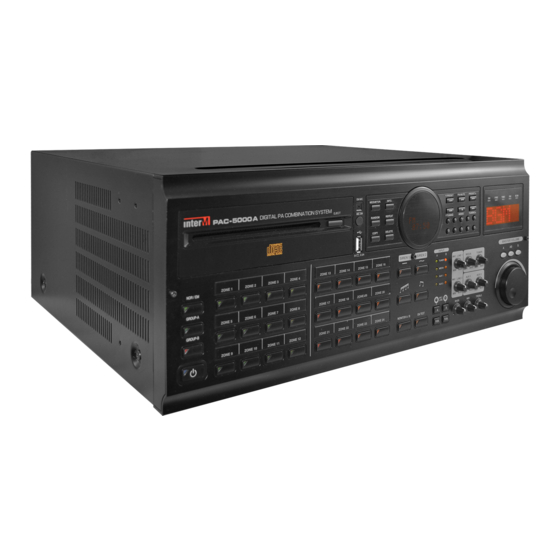
Многозонная цифровая система
оповещения
РАС-5000
Advertising
(скачивание инструкции бесплатно)
Формат файла: PDF
Доступность: Бесплатно как и все руководства на сайте. Без регистрации и SMS.
Дополнительно: Чтение инструкции онлайн
Инструкция по эксплуатации
Многозонная цифровая система
оповещения
РАС-5000
Страница:
(1 из 16)
навигация

1

2

3

4

5

6

7

8

9

10

11

12

13

14

15

16
Оглавление инструкции
- Страница 1 из 17
Инструкция по эксплуатации Многозонная цифровая система оповещения РАС-5000 - Страница 2 из 17
Содержание Распаковка……………………………………………………………………………………………. 3 Инсталяция …………………………………………………………………………………………… 3 - Страница 3 из 17
Распаковка Перед началом работы уделите несколько минут данной инструкции, ознакомьтесь с правилами установки и эксплуатации данной системы. Убедитесь в том, что оборудование поставлено в оригинальной заводской упаковке, в противном случае, Вы имеете право вернуть его назад поставщику. Установка - Страница 4 из 17
Назначение Комбинированная система PAC-5000, содержит встроенные музыкальные источники, встроенный селектор на 24 зоны, встроенные усилители мощности. Система может работать самостоятельно, выполняя функции музыкальной трансляции и аварийного оповещения. Для дистанционного управления, к данной - Страница 5 из 17
3-х полосный эквалайзер 3-х полосная регулировка частот доступна при подключении ПС. Удаленные микрофонные консоли К системе может быть подключено до 4-х микрофоннных консолей SI-100. Для управления 120 зонами к каждой консоли необходимо подключить клавиатуру расширения SR-100KR. Встроенный - Страница 6 из 17
Передняя панель 1. КНОПКА POWER (СЕТЬ) — Нажатие этой кнопки в положение ON включает данное устройство. При этом индикатор загорается красным цветом. Основной выключатель питания находится на задней панели. 2. КНОПКИ GROUP-A/B – Нажатие данных кнопок подключают группу А (1-12 зоны), либо группу В - Страница 7 из 17
12. 13. 14. 15. 16. 17. 18. 19. 20. 21. что при одновременной трансляции с нескольких микрофонов, сигнал 1 микрофона приглушает остальные. РЕГУЛЯТОРЫ УРОВНЯ ЗВУКА – Данные регуляторы используются для увеличения, уменьшения уровня звука MIC1~MIC5, AUX1/2, TUNER, CD. ОБЩИЙ РЕГУЛЯТОР ГРОМКОСТИ – - Страница 8 из 17
Задняя панель 1. РОЗЕТКА POWER (AC INLET) – К данной розетке подключается шнур для подачи питания 220В на данный блок. 2. КЛЕММЫ ДЛЯ ПОДКЛЮЧЕНИЯ АКУУМУЛЯТОРОВ И ИХ ПОДЗАРЯДКИ – К данным клеммам подключаются аккумуляторы 24В. Внутри блока находится устройство, обеспечивающее их подзарядку. 1) При - Страница 9 из 17
4. ТЕРМИНАЛ ПОДКЛЮЧЕНИЯ УСИЛИТЕЛЕЙ – Данный терминал используется для подключения внутренних (2х120Вт) или внешних (2х500Вт) усилителей (в зависимости от мощности зон). Не перепутайте полярности при подключении усилителей. 1) Подключение внутренних усилителей осуществляется так, как показано на - Страница 10 из 17
6. ТЕРМИНАЛ CONTROL OUT ТЕРМИНАЛ PD – С данных клемм снимается сигнал для управления блоком питания или для удаленного контроля. Сигнал на этом разъеме формируется при включении всех зон, или в аварийном режиме. ТЕРМИНАЛ ЕМ – Данные клеммы используются для управления внешним блоком аварийного - Страница 11 из 17
дополнительных (SLAVE) блоков. Внешние звуковые источники подключаются к основному блоку. На дополнительные же блоки, поступает общий выходной звуковой сигнал, по каждой группе отдельно. 1) ТЕРМИНАЛ LINK IN: К данному терминалу подключается разъем, на котором присутствуют сигналы управления, а - Страница 12 из 17
ВНИМАНИЕ: Перед включением удостоверьтесь, что Вы не назначили 2-м блокам одинаковые адреса. 15. РАЗЪЕМ REC MIC INPUT – Вы можете записать аварийное сообщение, при подключении к данному входу звукового источника. 16. РОЗЪЕМ AUX INPUT (AUX1,2) – Используется для подключения внешних, дополнительных - Страница 13 из 17
Технические характеристики Напряжение питания Потребляемая мощность Измеренная потребляемая мощность Выход усилителей (Группа А, Группа В) Частотный диапазон Чувствительность LIN входа Отношение Сигнал/Шум Чувствительность MIC входа Частотный диапазон MIC входа Фантомное питание Коэффициент - Страница 14 из 17
Блок диаграмм группа компаний Эскорт, тел./факс: (495) 937-5341, 674-2690 e-mail: info@escortpro.ru, http://www.escortpro.ru 14 - Страница 15 из 17
Подключение группа компаний Эскорт, тел./факс: (495) 937-5341, 674-2690 e-mail: info@escortpro.ru, http://www.escortpro.ru 15 - Страница 16 из 17
Габариты группа компаний Эскорт, тел./факс: (495) 937-5341, 674-2690 e-mail: info@escortpro.ru, http://www.escortpro.ru 16 - Страница 17 из 17
-
Contents
-
Table of Contents
-
Bookmarks
Quick Links
Operation
anual
(Program Installation)
Digital P Combination System
P C-5000 /5600
Related Manuals for Inter-m PAC-5000A
Summary of Contents for Inter-m PAC-5000A
-
Page 1
Operation anual (Program Installation) Digital P Combination System P C-5000 /5600… -
Page 2: Table Of Contents
DIGITAL PA COMBINATION SYSTEM Contents Contents P C-5000 Series Program Settings ………………..1 1. Installation for basic program…………………..1 Remote Control via PC Program (P C-5000 Series Only) …………4 I. System Connection ……………………4 II. Preferences (Environment) Setting………………..5 III. Screen Configuration and Program Functions…………….11 IV.
-
Page 3: P C-5000 Series Program Settings
DIGITAL PA COMBINATION SYSTEM P C-5000 Series Program Settings P C-5000 Series Program Settings 1. Installation for basic program 1) Run ‘setup.exe’ to start. When the setup screen appears (shown below), click [Next(N)] button. PAC-5000A/5600…
-
Page 4
DIGITAL PA COMBINATION SYSTEM 2) Screen display for setting installation folder. Click [Browse(R)] button to select where the program will be installed. After selecting, click [Next(N)] button. 3) Ready to install screen. Click [Next(N)] button. PAC-5000A/5600… -
Page 5
DIGITAL PA COMBINATION SYSTEM 4) Installation screen. Please wait until the installation is completed. 5) Installation completed screen. Click [Close(C)] button. Run the program after completing the installation. PAC-5000A/5600… -
Page 6: Remote Control Via Pc Program (P C-5000 Series Only)
④ After adding the accounts and running the program, following screen appears, enter user ID and Password to proceed. ※ NOTE: After registration, do not forget the ID and Password. PAC-5000A/5600…
-
Page 7: Preferences (Environment) Setting
Basic Environment Setup Menu. • The configuration start-up screen. Click “Start Environment Setup” button to start. • Select Serial communication port. COM1 is recommended, use COM2 if COM1 is being used or is not working. • Click [NEXT >] button to proceed. PAC-5000A/5600…
-
Page 8
PC is connected to the Server from remote location, select “Client” and input IP numbers and port number (recommended 2000). • Click [NEXT >] button. • Click the “Save Environment” button, configuration is now complete. • Please restart the program once the configuration is completed. PAC-5000A/5600… -
Page 9
• Close: Closes the window. NOTE: If ID/PW are lost/forgotten, please contact appropriate customer support team. ③ Equipment Setup Set the total number of connected devices. ④ Serial Port Setup Set Serial Communication port. ⑤ Server / Client Setup Set (Server/Client) type. PAC-5000A/5600… -
Page 10
⑥ Zone Name Setup For each (MASTER/SLAVE 1~4) area names can be entered. Select the equipment (MASTER/SLAVE 1~4) enter the name and click the [Save] button to apply. ⑦ RM Macro Setup Screen for setting the Broadcast Area of macro RM Zone. PAC-5000A/5600… -
Page 11
— Clicking [Download / Save] button will apply macro setting to the equipment. — Click the [Cancel] button to close the window. ※ If [Cancel] button is clicked before clicking [Download / Save], set macro information will NOT be applied to the equipment. PAC-5000A/5600… -
Page 12
— Clicking [Download / Save] button will apply macro setting to the equipment. — Click the [Cancel] button to close the window. ※ If [Cancel] button is clicked before clicking [Download / Save], set macro information will NOT be applied to the equipment. PAC-5000A/5600… -
Page 13: Screen Configuration And Program Functions
Controls Speaker ZONE, FUNCTION, Volume, Chime & Siren etc. — Click meter level using the mouse cursor to adjust the volume. To control both group A and B at the same time, click the Sync (AB) button between A and B meter level to activate. PAC-5000A/5600…
-
Page 14: Pc Reserved Broadcast Settings
⑤ Network Status Icon Displays the network connection status of the PC. Click the icon to connect or disconnect. — Program connected to PAC-5000A is Server and program that connects from remote location is Client. — Icon Status Description ▶ Server Program.
-
Page 15
Ⓒ Select a Day to broadcast. Ⓓ Enter the broadcast start time. (Use ▲/▼ buttons to change AM/PM) Ⓔ Select the broadcast Speaker ZONE. Ⓕ Click the Add button to set the scheduled content . Scheduled broadcast will begin at the set time. PAC-5000A/5600… -
Page 16
Scheduled broadcast can only be deleted in [STOP] state. If scheduled broadcast is in process click [STOP] button and set as follows. Ⓐ Select the content to delete using the mouse. Ⓑ Click [Delete] button to display confirmation window. Ⓒ Click [Yes(Y)] button to delete the selected setting. PAC-5000A/5600… -
Page 17
Scheduled broadcast can only be modified in [STOP] state. If scheduled broadcast is in process click [STOP] button and set as follows. Ⓐ Click the content to modify. Ⓑ Modify the content. Ⓒ Click [Modify] button to set modified content. PAC-5000A/5600… -
Page 18
DIGITAL PA COMBINATION SYSTEM IV.4 Run Reserved Broadcast Ⓐ After setting the reserved broadcast, clicking the [RUN] button will operate with configured information. PAC-5000A/5600… -
Page 19
Ⓐ During the reserved broadcast, clicking [STOP] button will stop the broadcast. Ⓑ If the [STOP] button is clicked during non-reserve broadcast, Ⓑ screen is displayed. If [Yes(Y)] button is clicked, set scheduled broadcast function will not work. Click the [RUN] button to operate the scheduled broadcast again. PAC-5000A/5600… -
Page 20: Eq Setting
Set the EQ setting as shown below. ① Select the group to EQ set control. ② Set the EQ of the selected group. ③ Set EQ settings can be added to preset and also can [ADD] or [DEL] delete presets. PAC-5000A/5600…
-
Page 21: Server / Client Pc Utilization
• PC that runs the Server program is set as “Server”. • PC that runs Client program is set as “Client” and IP and PORT numbers of access/connect PC must be entered. (Access/connect PC is the PC running the Server program.) PAC-5000A/5600…
-
Page 22
Clicking the icon once more will allow connection. To reconnect, icon must be clicked from a PC set as Client. — Program ends when the window is closed. ※ Note: If communication is interrupted/terminated due to a physical causes, shut down the program and restart. PAC-5000A/5600… -
Page 23: Remote Control Via The Internet (P C-5600 Only)
ㄴ. Set the computer’s network in order to communicate with the device and to each other. ※ If the computer’s wireless network is turned on, turn it off and proceed. ※ Please download the latest version of the manual as manual may change depending on the firmware version. (www.inter-m.com) PAC-5000A/5600…
-
Page 24
Browser version 6.1 or higher. ㄹ. After connecting, a pop-up window will appear asking for access password. Input as shown below. — ID: admin — Password: 1 ※ For security reasons, the equipment should be used only after a change of password. PAC-5000A/5600… -
Page 25: Common Screen
① Name of the device connected to the web is displayed. ② Set the language of the web page. ③ Displays the information of web connected device. (Device Name/Device IP/Web Version) ④ Menu available from the web page. ⑤ Corresponding screen is displayed when menu is selected. PAC-5000A/5600…
-
Page 26: Ii.1 Front (Front Panel)
① Can control front panel functions from a web page. ② When multiple devices are connected, select the device to control the Zone status. Unconnected State Connected State Controllable State ③ [Front] (Front Panel) Help & Tips are displayed. PAC-5000A/5600…
-
Page 27: Ii.2 Volume
② Selected from ①, set ZONE A Volume level (0 ~ 48). ③ Selected from ①, set ZONE B Volume level (0 ~ 48). ④ Selected from ①, set ZONE A, B Volume levels (0 ~ 48) at the same time. ⑤ [Volume] Help & Tips are displayed. PAC-5000A/5600…
-
Page 28: Ii.3 Eq (Equalizer)
※ When adding preset, preset name cannot have (space) or be a duplicate name. ③ Delete the added preset. ④ Set the EQ (Equalizer) values (-12dB ~ 12dB) in Zone A. ⑤ Set the EQ (Equalizer) values (-12dB ~ 12dB) in Zone B. ⑥ [EQ] Help & Tips are displayed. PAC-5000A/5600…
-
Page 29: Ii.4 Network Setup
③ Can see the network configuration settings of the device and also set the desired information. ④ Click [Apply] button to apply the modified information from steps ② and ③. ⑤ Click [Initialize] button to reset the modified information from steps ② and ③. ⑥ [Network Setup] Help & Tips are displayed. PAC-5000A/5600…
-
Page 30: Ii.5 Rm Macro Setup (Remote Microphone Macro Setup)
⑤ Click [Data Initialization] (Macro Initialization). All configured information from steps ①~④ will reset. ⑥ Click [Apply the data] (Macro Apply). All configured information from steps ①~④ will be applied. ⑦ [RM macro Setup] (Remote Microphone Macro Setup) Help & Tips are displayed. PAC-5000A/5600…
-
Page 31: Ii.6 Fire Macro Setup
⑤ Click [Data Initialization] (Macro Initialization). All configured information from steps ①~④ will reset. ⑥ Click [Apply the data] (Macro Apply). All configured information from steps ①~④ will be applied. ⑦ [Fire Macro Setup] Help & Tips are displayed. PAC-5000A/5600…
-
Page 32: Ii.7 Em Mic Macro Setup
② Click [Select All]. All broadcast area is selected. ③ Click [Release All]. All broadcast area is deselected. ④ Click [Apply the data] (Macro Apply). All configured information from steps ①~④ will be applied. ⑤ [EM Mic Macro Setup] Help & Tips are displayed. PAC-5000A/5600…
-
Page 33: Ii.8 Schedule Setup
② Add a schedule broadcast [Add] (max 50), [Delete], [Modify] and display the result in a table format. ③ Add holiday periods (max 30), and also delete. ④ Download or upload set schedule information. ⑤ Download or upload set holiday information. ⑥ [Schedule Setup] Help & Tips are displayed. PAC-5000A/5600…
-
Page 34
① Enter the name of the scheduled broadcast. ② Set the time of the scheduled broadcast. ※ If the audio source is from the PC audio, time can be set. ③ Set the day of the scheduled broadcast. PAC-5000A/5600… -
Page 35
① The stored broadcast schedule list is displayed. Check/Click the schedule of broadcast to delete from the list. ② Click [Delete] Checked item(s) from step ① will be deleted from the list. ③ Click [Select All] Entire list of scheduled broadcast will be deleted. PAC-5000A/5600… -
Page 36
① Stored schedule data list is displayed and selected data can be modified. ② Enter the name of the scheduled broadcast. ③ Set the time of the scheduled broadcast. ※ If the audio source is from the PC audio, time can be set. ④ Set the day of the scheduled broadcast. PAC-5000A/5600… -
Page 37
※ If the source type is PC audio, the source file name information is not displayed. ③ Clicking the mouse will display the area information of the schedule. ④ Time information of the schedule is displayed. ⑤ Day information of the schedule is displayed. PAC-5000A/5600… -
Page 38
Above is the screen that appears when [Delete] button is clicked in [Holiday] setting screen. ①Stored holiday list is displayed. Check/Click the holiday data to be deleted from the list. ② Click [Delete] to delete the checked holiday data from step ①. ③ Click [Select All] to delete the entire holiday data displayed. PAC-5000A/5600… -
Page 39: Ii.9 File Manage (File Management)
① Files that can be used for time schedule is displayed. If there is a file to delete, select the file and click Delete button to delete. ② Can upload a new file and the disk capacity is displayed. ③ [File Manage] (File Management) Help & Tips are displayed. PAC-5000A/5600…
-
Page 40: Ii.10 Time Setup (Time/Date Setup)
Can set periodic time to synchronize the clock. (ex: If set for 15:00 hour, at every 3:00pm, synchronization sets the time on the device.) ④ Click [Apply] button to apply the set time. ⑤ [Time Setup] Help & Tips are displayed. PAC-5000A/5600…
-
Page 41: Ii.11 View Log
Above is a screen display when [View Log] menu is clicked. ① Logs generated during the operation are displayed. ② Click [Refresh] button to reload the log. ③ Click [Clear Log] button to clear the log information. ④ [View Log] Help & Tips are displayed. PAC-5000A/5600…
-
Page 42: Ii.12 Upgrade System
※ S/W Upgrade extensions: .tar.gz ※ Mainboard Upgrade extensions : .bin ② Click [Apply] button to upgrade the selected file to the device. ③ Click [Initialize] button to reset the file selected in step ①. ④ [Upgrade System] Help & Tips are displayed. PAC-5000A/5600…
-
Page 43: Ii.13 Restart System
DIGITAL PA COMBINATION SYSTEM II.13 Restart System ① ② Above is a screen display when [Restart System] menu is clicked. ① Click [Apply] button to restart the system. ② [Restart System] Help & Tips are displayed. PAC-5000A/5600…
-
Page 44: Ii.14 Factory Set System
DIGITAL PA COMBINATION SYSTEM II.14 Factory Set System ① ② Above is a screen display when [Factory Set System] menu is clicked. ① Click [Apply] button to set back to factory default settings. ② [Factory Set System] Help & Tips are displayed. PAC-5000A/5600…
-
Page 45: Ii.15 Password Change
① Enter the current password. ② Enter new password. ③ Enter new password once more. ④ Click [Apply] button to change to new password. ⑤ Click [Initialize] button to reset the newly entered password. ⑥ [Password Change] Help & Tips are displayed. PAC-5000A/5600…
-
Page 46
NOTE PAC-5000A/5600… -
Page 47
PAC-5000A/5600… -
Page 48
Inter-M, Ltd. (Korea) began operations in 1983. Since then, Inter-M has grown to become one of the largest manufacturers of professional audio and commercial sound electronics equipment in the world. Inter-M has gained worldwide recognition for its own branded products, as well as private label manufacturing of electronics sold under other names (OEM).
This manual is also suitable for:
Pac-5600
— Поиск по каталогу —
Производитель:
Категория:
Название:
Описание:
— Многоканальные телефоны —
+7 (812) 708-01-19
+7 (812) 708-01-19
![]()
![]()


![]()

![]()


![]()

![]()
![]()


![]()


![]()
![]()

![]()
![]()

![]()
![]()
![]()
![]()
![]()


![]()
![]()
![]()

![]()

- DFS
- MOXA
- SC&T
- SF&T
- ФОРМАТ-2
- ФОРМАТ-100
- optex
- Best-DVR
- РЛД Редут-500
- СП4У40
- A-120
|
Руководство пользователя PAC-5000.pdf
Скачать |
|
| Описание: |
Руководство пользователя PAC-5000 |
| Размер: | 23112.798828125 Kb |
| Тип файла: |

Контакты:
Телефон/факс: (812) 708-01-19
E-mail: info@iskra-spb.ru
Адрес: 197374, г. Санкт-Петербург, ул. Оптиков, д. 4
Инструкция по эксплуатации Многозонная цифровая система оповещения РАС-5000
Содержание Распаковка……………………………………………………………………………………………. 3 Инсталяция …………………………………………………………………………………………… 3
Распаковка Перед началом работы уделите несколько минут данной инструкции, ознакомьтесь с правилами установки и эксплуатации данной системы. Убедитесь в том, что оборудование поставлено в оригинальной заводской упаковке, в противном случае, Вы имеете право вернуть его назад поставщику. Установка
Назначение Комбинированная система PAC-5000, содержит встроенные музыкальные источники, встроенный селектор на 24 зоны, встроенные усилители мощности. Система может работать самостоятельно, выполняя функции музыкальной трансляции и аварийного оповещения. Для дистанционного управления, к данной
3-х полосный эквалайзер 3-х полосная регулировка частот доступна при подключении ПС. Удаленные микрофонные консоли К системе может быть подключено до 4-х микрофоннных консолей SI-100. Для управления 120 зонами к каждой консоли необходимо подключить клавиатуру расширения SR-100KR. Встроенный
Передняя панель 1. КНОПКА POWER (СЕТЬ) — Нажатие этой кнопки в положение ON включает данное устройство. При этом индикатор загорается красным цветом. Основной выключатель питания находится на задней панели. 2. КНОПКИ GROUP-A/B – Нажатие данных кнопок подключают группу А (1-12 зоны), либо группу В
12. 13. 14. 15. 16. 17. 18. 19. 20. 21. что при одновременной трансляции с нескольких микрофонов, сигнал 1 микрофона приглушает остальные. РЕГУЛЯТОРЫ УРОВНЯ ЗВУКА – Данные регуляторы используются для увеличения, уменьшения уровня звука MIC1~MIC5, AUX1/2, TUNER, CD. ОБЩИЙ РЕГУЛЯТОР ГРОМКОСТИ –
Задняя панель 1. РОЗЕТКА POWER (AC INLET) – К данной розетке подключается шнур для подачи питания 220В на данный блок. 2. КЛЕММЫ ДЛЯ ПОДКЛЮЧЕНИЯ АКУУМУЛЯТОРОВ И ИХ ПОДЗАРЯДКИ – К данным клеммам подключаются аккумуляторы 24В. Внутри блока находится устройство, обеспечивающее их подзарядку. 1) При
4. ТЕРМИНАЛ ПОДКЛЮЧЕНИЯ УСИЛИТЕЛЕЙ – Данный терминал используется для подключения внутренних (2х120Вт) или внешних (2х500Вт) усилителей (в зависимости от мощности зон). Не перепутайте полярности при подключении усилителей. 1) Подключение внутренних усилителей осуществляется так, как показано на
6. ТЕРМИНАЛ CONTROL OUT ТЕРМИНАЛ PD – С данных клемм снимается сигнал для управления блоком питания или для удаленного контроля. Сигнал на этом разъеме формируется при включении всех зон, или в аварийном режиме. ТЕРМИНАЛ ЕМ – Данные клеммы используются для управления внешним блоком аварийного
дополнительных (SLAVE) блоков. Внешние звуковые источники подключаются к основному блоку. На дополнительные же блоки, поступает общий выходной звуковой сигнал, по каждой группе отдельно. 1) ТЕРМИНАЛ LINK IN: К данному терминалу подключается разъем, на котором присутствуют сигналы управления, а
ВНИМАНИЕ: Перед включением удостоверьтесь, что Вы не назначили 2-м блокам одинаковые адреса. 15. РАЗЪЕМ REC MIC INPUT – Вы можете записать аварийное сообщение, при подключении к данному входу звукового источника. 16. РОЗЪЕМ AUX INPUT (AUX1,2) – Используется для подключения внешних, дополнительных
Технические характеристики Напряжение питания Потребляемая мощность Измеренная потребляемая мощность Выход усилителей (Группа А, Группа В) Частотный диапазон Чувствительность LIN входа Отношение Сигнал/Шум Чувствительность MIC входа Частотный диапазон MIC входа Фантомное питание Коэффициент
Блок диаграмм группа компаний Эскорт, тел./факс: (495) 937-5341, 674-2690 e-mail: info@escortpro.ru, http://www.escortpro.ru 14
Подключение группа компаний Эскорт, тел./факс: (495) 937-5341, 674-2690 e-mail: info@escortpro.ru, http://www.escortpro.ru 15
Габариты группа компаний Эскорт, тел./факс: (495) 937-5341, 674-2690 e-mail: info@escortpro.ru, http://www.escortpro.ru 16