
Компания Баджер т. (812) 320 55 65
WWW
.BADGER.RU
ВВЕДЕНИЕ
Вы сделали правильный выбор, приобретя эхолот “Outlook” производства корпорации “Интерфэйз”. Эхолот
надежно и компактно изготовлен, что позволяет устанавливать его практически на любом судне. “Outlook”
укажет глубину толщи воды, состояние дна и обнаружит плавающие под водой объекты вроде рыбы и т.п.,
прямо впереди судна по курсу. Поможет в этом большой дисплей эхолота, отображающий самые мелкие
детали. Излучатель “Outlook” можно устанавливать как в отверстии днища, так и на транце судна.
В конструкции эхолота “Outlook” заложено огромное количество оригинальных технических решений и
новинок, что обеспечивает Вашу безопасность при управлении судном и повышает эффективность рыбной
ловли. Жидкокристаллический дисплей эхолота имеет высокое разрешение, что обеспечивает необходимую
подробность изображения дна и плавающих объектов при любом из четырех возможных режимов
увеличения. Встроены и могут быть применены сигнал обнаружения эхолотом рыбы и сигнал уменьшения
глубины впереди по курсу судна менее заданной величины. Возможно ручное или автоматическое
масштабирование изображения на экране, можно вывести на экран индикатор плотности поверхности дна
и выбрать символы для обозначения различных сортов рыбы.
“Outlook” можно настроить для работы на один из 9 языков по выбору английский, французский,
итальянский, испанский, немецкий, датский, финский, шведский или греческий. Энергонезависимая
память эхолота сохранит выбор рабочего языка, диапазон просматриваемых глубин, увеличение и
контрастность экрана, настройки экрана и конфигурацию экранных меню. “Outlook” может одновременно
выполнять несколько различных операций, причем на экране можно следить за любой операцией, не
останавливая выполнение других (многозадачность) операций без потери информации.
Для того, чтобы наиболее полно воспользоваться многообразными возможностями эхолота “Outlook”, прежде
всего внимательно прочтите настоящее Руководство. В памяти эхолота “Outlook” хранится программа,
демонстрирующая основные приемы работы. Мы настоятельно рекомендуем не пожалеть времени и
хорошенько во всем разобраться, чтобы легко все это использовать в деле. Мы рекомендуем прочесть
настоящее Руководство даже прежде, чем приступить к установке эхолота.
Гарантийные Обязательства
“Интерфэйз” гарантирует нормальную работу эхолота “Outlook” в течении гарантийного срока.
Рекомендуется ознакомиться с текстом гарантийных обязательств “Интерфэйз” (копия имеется в конце
Руководства) и точно следовать им в случае необходимости провести гарантийных ремонт эхолота.
Настоятельно рекомендуется сохранить оригинальную упаковку эхолота, что обеспечит надежное
сохранение всех частей прибора в случае необходимости пересылки его для ремонта. Дисплей эхолота следует
упаковать в пластиковый мешок с “пузырьками” и уложить в коробку с картонными перегородками, что
защитит прибор от вибрации и возможных повреждений при транспортировке. Не требуется вкладывать в
посылку крепежную раму и струбцины, однако рекомендуется постараться вместе с дефектным эхолотом
прислать и применяемый излучатель. Не следует высылать в наш адрес также кабель электропитания, если
только у владельца не возникло сомнений в наличии повреждений этого кабеля (при подключении разъем
№1 соединяется с красным проводом).
Когда будете разбираться с возможными проблемами, обратитесь для начала к разделу “Разрешение проблем”
(стр.37 настоящего Руководства), где описаны наиболее частно встречающиеся затруднения и способы
разрешения их. Если в проблеме не удается разобраться, обращайтесь к своему дилеру или непосредственно
в “Интерфэйз”.
4
-
Contents
-
Table of Contents
-
Troubleshooting
-
Bookmarks
Quick Links
Related Manuals for Interphase Proble
Summary of Contents for Interphase Proble
-
Page 1
PERATION ANUAL… -
Page 2
To Our Customer: Thank you for choosing the Interphase Probe Forward Scanning Sonar. Throughout the development of this fine product, we have been primarily concerned with creating a unit that offers the best possible value for your money. Selection of features, ease of use, superior performance and outstanding reliability were the benchmarks upon which all important design decisions were made. -
Page 3: Table Of Contents
Table Of Contents Important Notice Principle of Operation Display Unit Installation Selecting the Transducer configuration for Your Boat ______________________________________________ 10 Transducer Installation Basic Operation Getting Started Set-Up View Demo Program, Display Contrast Units of Measure Language Selection Level Adjustment Forward View (Full Scan) Range Adjustment Sensitivity Adjustment Alarm Adjustment…
-
Page 4: General Information
Refer to the accessories part numbers printed in the Transducer Installation section (Page 17) of this manual, then see your dealer or call Interphase to order. The Probe has an unprecedented number of advanced features, in addition to the forward scanning capability, to make your boating safer and your fishing more productive.
-
Page 5: Warranty Information
The enclosed warranty registration card must be completed and returned to Interphase within 15 days of purchase so that your unit may be protected under the warranty. Failure to return the warranty card may cause unnecessary delays in processing your unit for warranty repair.
-
Page 6: Principle Of Operation
«real time» or «live action» mode. Interphase has taken this same technology and modified it for use in the marine market.
-
Page 7
acoustic beam, the phased array has other patent pending advantages over fixed-beam technologies, such as: allowing the user to adjust the transducer beam width, to scan large areas limited only by the physics of the speed of sound in water (5,000 feet/second), and the ability to provide nearly real time or live action underwater views. -
Page 8: Display Unit Installation
DO NOT SHORTEN THE TRANSDUCER CABLE. If a transducer cable longer than the 30’ length supplied with your unit is needed, please contact your Interphase dealer. A 30-foot scanning sonar transducer extension cable is available. (P/N 04-0014-008)
-
Page 9
DANGER: Removal of any connector, disassembly of transducer, shortening of any cable or use of any cable other than that supplied by Interphase will void your warranty. NO EXCEPTIONS. Cable Connectors (view from front of female plug) Transducer: 1 White 1st element… -
Page 10: Selecting The Transducer Configuration For Your Boat
Selecting the Transducer Configuration for your Boat Keep in mind the primary rule for transducer operation. This is: the transducer can function as long as it has an unobstructed forward view and has smooth flowing non-aerated water surrounding it. The first line of inquiry should be about the boat. Transom mounted transducers are intended for low speed boats with external props.
-
Page 11: Transducer Installation
If you need a longer length cable than comes with the transducer (30’), then purchase the optional 30’ extension cable, Interphase Part # 04-0014-008. It is recommended that only one extension cable be used as additional extensions will decrease the effective power and depth range.
-
Page 12
Tighten the nut to 50 inch pounds of torque before operating the boat. 30’ Extension Cable 9-pin Interphase Part # Male 04-0014-008 Transom Mount Bracket in Released Position Suggested materials required for installation: ♦… -
Page 13
Bracket Axle Nylok Nut Kick-up Bracket Replacement Parts If during installation parts are somehow lost are damaged, they can be replaced as follows: Part# 17-0088-008 — Spray Shield Kit — Includes: Spray Shield, four Mounting Bolts and Nuts, Rubber Grommet and four Large Mounting Screws. -
Page 14
The transducer can be installed on either side of an outboard or inboard/outboard engine, or between twin outboards. For single engine installations, normally 18” to 24” outboard of the propeller center line is acceptable and the down stroke side of the propeller is preferred. Choose a location where water flow is smoothest. -
Page 15: Selecting The Best Location
Suggested Thru-Hull Transducer Locations Fin Keel ~ 1/3 L L = waterline length Displacement Hull Planing Hull Thru-Hull Transducer Installation The thru-hull transducer is the recommended choice for larger boats with in-board engines. Thru-hull mounting is usually required on larger power and sail craft in order to find a mounting location free of forward looking hull obstructions.
-
Page 16
DO NOT install a bronze transducer housing directly into an aluminum or steel hull because electrolytic corrosion will occur. Consult your boat-yard for information on stainless or plastic sleeves. IMPORTANT: 1) Make sure the water flow across the thru-hull transducer is bubble and turbulence free at all speeds if good performance is to be achieved. -
Page 17
MOLDED FAIRING BLOCK If your installation requires a fairing block, you may either have one made locally, or purchase a molded plactic unit from Interphase or your Interphase distributor. For this transducer, the molded Fairing Block Part Number is: 42-2004-000… -
Page 18: Basic Operation
Interphase Probe Power On/ Softkeys Short-cut In this manual you will find instruction on how to change all adjustable settings by using the “soft keys”. However, any setting adjustment can be done (when the appropriate menu selection is made) by turning the control knob.
-
Page 19
Pre-Programmed Screen Displays Interphase Probe Rather than ask you to “build” different screen displays while operating the unit, the Probe has seven of the most valuable LCD screen displays pre-programmed into its operating system memory. Thanks to the Multi-Tasking operating system, each… -
Page 20
Common Soft Key Functions The Probe’s innovative Multi-Tasking operating system is Control Center Softkey Menu controlled through the Control Center, where several different screen displays (views) can easily be selected by the push of a button. Each of these screens (views) reside in the Probe’s internal memory and all are being updated in the background, regardless of which screen is currently being displayed. -
Page 21
Track Plotter settings. In order to make changes to the downlooking Chart display, you must go to a display where the Chart display is on the right side of the display (such as the Chart mode). In addition to the fact that the softkey menu typically relates to only the right side of the split screen displays, other features such as Bottom Hardness and Fish Symbols will not appear in Zoomed, Bottom Track or Bottom Locked displays. -
Page 22: Getting Started
Interphase Customer Service Department (831) 477-4944 immediately. WARNING: DO NOT operate the Probe with parts missing or with parts other than those obtained through Interphase; doing so could cause a malfunction in the unit. Any malfunctions to the Probe resulting from unauthorized parts are not covered by warranty.
-
Page 23
PLOT View (Track Plot) DATA View (Large Digits) CHART/PLOT View FWD View (Forward Scan) SET-UP View (Languages, etc.) CHART/SCAN View CHART View (Conventional) -
Page 24: Set-Up View
Set-Up View The Probe includes a SET-UP View where the DEMO program can be activated, the units of measure and language can be selected. The display contrast can be adjusted by turning the front panel rotating knob. The Probe s internal backup battery will remember all settings for future use.
-
Page 25: Language Selection
The choices and their settings are as follows: Feature U.S. Nautical Depth/Range Feet Fathoms (Ft.) (Fa) Water Temp (ºF) (ºF) Boat Speed Mi./Hr. Knots (MPH) (KT) Distance Log Miles Naut. Mi (Mi) (NMi) Nav. Track Plot Miles Naut. Mi (Mi) (NMi) Select Menu Language The Probe allows the selection of 9 operating languages;…
-
Page 26: Forward View (Full Scan)
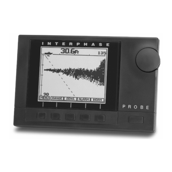
Forward View (Full Screen) 10.3 While in the Control Center press the leftmost button labeled «FWD» to view a full screen forward looking display. At the top left of the screen the current depth beneath the boat is shown in digital numbers. If the optional speed/temperature transducer is connected to the unit, the boat’s speed is displayed just to the left of the digital depth as shown on the picture at left.
-
Page 27: Alarm Adjustment
Alarm Adjustment In the forward looking display or view, alarms may be set for targets which are shallower than, deeper than, or within a specific zone of adjustable depth settings. To adjust or clear the alarm settings, press the soft key labeled “ALARM”…
-
Page 28: Beam Width & Direction Adjustment
Beam Sector Width & Steer Adjustment The large rotary knob labeled “BEAM” can be used to both adjust the beam scanning sector width and the direction of the scan. For example, you may not want to scan the full 90 degree sector from the surface ahead to beneath the boat, but instead only to scan from the surface ahead to a certain depth below the surface.
-
Page 29: Plot (Track Plot) View
If your separate Loran C, Decca or GPS receiver has the proper NMEA 0183 (version 2.0 non-differential) output capability, or if you own the Interphase Star Pilot GPS, Pilot GPS or Interphase Pilot Loran, you can easily interface the unit to the Probe to show both digital and graphic navigation information.
-
Page 30: Center
Track Plotter Symbols Starting Position Waypoint selected in navigation receiver Center of plot screen Center By pressing the «CENTER» soft key, your current position will be moved to the center of the track plot display and the track line dots will be shifted accordingly. Reset The «RESET»…
-
Page 31: Chart View
Chart View (Conventional downlooking) The Probe’s phased array transducer can be electronically steered to look directly below the boat. In this mode the Probe LCD display will show a picture like conventional fixed beam down-looking fish finders. When in this mode, the Probe offers a full range of sophisticated features which are found on advanced conventional depth sounders such as split screen zoom, bottom lock, fish and depth alarms, bottom…
-
Page 32: Bottom Hardness
Hardness (White-Line) If the softkey labeled “HARD” is pressed, the display will show the bottom as a thin line separated by a shaded area. This mode can be used to find detail close to the bottom or to indicate the bottom composition. The thinner the shaded area the softer the bottom.
-
Page 33: Other Features
Bottom Track or Bottom Lock display. The high resolution Zoom is very useful when looking for extra detail on the bottom or in areas above the bottom. Because the Probe uses an Interphase unique Zoom Bar 4X over-sampling technique, the zoom actually shows more data than the non-zoomed picture.
-
Page 34: Fish Symbol Id
Split Screen Bottom Lock Display Zoomed Display with Fish Symbols ON Screen Scroll Speed If you move the zoom bar all the way to the bottom of the display, the Bottom Track and the Bottom Lock features can be activated.. When the Bottom Track feature is activated, the Zoom Bar changes to a thin bar extending from the top to the bottom of the display.
-
Page 35: Data View
Data View From the Control Center, press the soft key labeled «DATA» to see a split screen display with large digits on the left and a forward scanning view on the right. The large digits show the digital depth and, if your Probe is equipped with the optional speed/temperature transducer, the boat speed, surface water temperature, and distance traveled log.
-
Page 36: Alarm Adjustment
AUTO sensitivity mode and it will remain off until the “AUTO” soft key is again selected. Note: when AUTO mode is turned on the word AUTO will be displayed in reverse video (white letters on a black background). To exit the sensitivity menu and save your adjustments simply press the soft key labeled “LAST”…
-
Page 37: Beam Width & Direction Adjustment
Beam Sector Width & Steer Adjustment The large rotary knob labeled “BEAM” can be used to both adjust the beam scanning width and the direction of the scan. For example, you may not want to scan the full 90 degree sector from the surface ahead to beneath the boat, but instead only to scan from the surface ahead to a certain depth below the surface.
-
Page 38: Chart/Plot View
Chart/Plot View (split screen) In this view, the Probe shows a split screen display with a conventional down looking depth sounder picture on the left and a track plot display on the right. Pressing the «GO» soft key will bring up a sub-menu to allow adjustments to the track plotter display.
-
Page 39: Center
Center y pressing the «CENTER» soft key, your current position will be moved to the center of the track plot display and the track line dots will be shifted accordingly. Reset The «RESET» soft key in the menu restarts your track plotting by placing your present position in the center of the track plot screen and erasing all track line dots Note: All other past information, including track line…
-
Page 40: Chart/Scan View
Chart/Scan View (split screen) In this split screen view, the Probe shows a forward looking view on the right and a conventional down looking chart view on the left. In this view, adjustments can be made to the right side of the display (forward looking view) but not to the left side (conventional down looking display).
-
Page 41: Alarm Adjustment
Alarm Adjustment In the forward looking display or view, alarms may be set for targets which are shallower than, deeper than, or within a specific zone of adjustable depth settings. To adjust or clear the alarm settings, press the soft key labeled “ALARM”…
-
Page 42: Beam Width & Direction Adjustment
Beam Sector Width & Steer Adjustment The large rotary knob labeled “BEAM” can be used to both adjust the beam scanning width and the direction of the scan. For example, you may not want to scan the full 90 degree sector from the surface ahead to beneath the boat, but instead only to scan from the surface ahead to a certain depth below the surface.
-
Page 43: Nmea 0183 Interface
Decca, and GPS receivers in the NMEA 0183 data format. This interface has been tested and is verified to work with the Interphase Pilot GPS. It features a unique, fully dedicated microprocessor for the NMEA 0183 data port which provides maximum compatibility among Loran C, Decca and GPS receivers.
-
Page 44: Interpreting Your Probe Display
Strong Return from Wall Far-Forward Interpreting The Probe’s Forward Display The Interphase Probe provides a display which shows acoustic echo returns from the underwater area beneath and ahead of the vessel. The Phased Array Transducer steers an acoustic beam over an arc which can be adjusted from approximately 12 to 90 degrees.
-
Page 45: Distance Forward
Distance Forward Under typical conditions, the Probe will show level or shallowing bottom contours for a distance forward of between 4X to 6X the depth below the transducer. Obstructions in the water, such as walls, mud banks, etc. may be seen at much greater distances, subject to the depth below the transducer and the 1,200 ft.
-
Page 46
To minimize the sidelobe effect, the gain should be reduced. However, in some situations, you may want to ignore the sidelobe effect and increase the gain to achieve a better display of the bottom far-forward of the vessel. TVG (Time Variable Gain) As the acoustic signal travels through the water it is attenuated in strength and also loses strength because the signal is being spread over a larger and larger area. -
Page 47: Reference Information
Reference Information Phased Array Technology Most existing depthsounders and fishfinders in the marine market use a mature “fixed beam” technology which was originally developed during W.W. II to detect the presence and distance of submarines. Products using this technology usually have a transducer mounted on the rear of the vessel, making contact with the water.
-
Page 48
In the future, Interphase believes that this multiple fixed- beam approach has serious limitations, especially for use in more adva ced products where maximum underwater coverage and resolution are important. -
Page 49
example, using an 8 element phased array, the Probe is capable of steering the acoustic beam in over 90 different directions. Conventional fixed-beam technology would have required the use of at least 90 transducer elements, each pointed in a different direction. Such a transducer would be much too costly and bulky to be of any practical use in the marine market. -
Page 50: Frequently Asked Questions (Faq’s)
Probe. How wide is the scanning beam? The phased array scanning beam on all Interphase scanning sonar operates with a 12 degree cone angle beam. This means that the diameter of the beam at 100′ is about 15′ wide.
-
Page 51
Can I see the display in bright sunlight? The Interphase LCD screen is one of the brightest displays in the industry. The backlight is a full width, cold fluorescent tube (reduces the chance of condensation). -
Page 52: Maintenance
Maintenance The Probe Forward Scanning Sonar has been designed to provide reliable, trouble-free performance for years. Follow the maintenance tips below to ensure that your Probe remains problem free. 1) Keep your Probe clean and dry. Occasionally wipe unit off with a damp cloth, but be careful not to scratch the lens covering the LCD screen.
-
Page 53: Troubleshooting Guide
Troubleshooting Guide If you are experiencing trouble with your Probe, please refer to the following checklist: PROBLEM Unit will not turn on. Unit beeps but no picture appears on the screen. Unit blows fuses. Loses picture at speed. LCD darkens in sunlight after prolonged use.
-
Page 54: Interference Problems
Interference Problems Interference can come from several sources. The most common of these are: 1) Other nearby depth sounders operating at the same frequency. 2) Radiated interference from the boat’s electrical system (alternator, distributor and spark plugs) or from nearby equipment that radiates electrical noise.
-
Page 55: Specifications
Specifications Depth only Transom Transducer Part # T1-I200-025 Display Type: Depth Ranges: Forward Ranges: Transmit Frequency: Zoom Ranges: Pulselength and Sounding Rates: Transmitter Power: Surface Water Temperature: Power Requirements: Dimensions: Standard Equipment: Specifications subject to change without notice. Depth only Thru-Hull Transducer Part # T1-I200-026 128 x 160 pixels;…
-
Page 56: Faxtory Reset And Speed Calibration
‘U’ fashion with the notch facing aft. Product Support: Monday thru Friday 8:00 AM 5:00 PM PST Phone: (831) 477-4944 ext. 16 Fax: (831) 462-7444 E-Mail: comments@interphase-tech.com Power Key Hold these keys as power key turned on…
-
Page 57: How To Obtain Service
Interference Problems. This information solves the most common problems. If problems persist, please call Interphase Technical Service at (831) 477-4944 or send your unit in with the information below filled out. If you do need to return your set, send it to the following address: Service Department Interphase Technologies, Inc.
-
Page 58
NOTES… -
Page 59: Warranty
From the second through the fifth year, Interphase will, at its option, repair or replace defective units for a fixed fee. This fee will be set at the beginning of each year.
This manual is also suitable for:
Probe
В представленном списке руководства для конкретной модели Эхолота — Interphase Probe TM. Вы можете скачать инструкции к себе на компьютер или просмотреть онлайн на страницах сайта бесплатно или распечатать.
В случае если инструкция на русском не полная или нужна дополнительная информация по этому устройству, если вам нужны
дополнительные файлы: драйвера, дополнительное руководство пользователя (производители зачастую для каждого
продукта делают несколько различных документов технической помощи и руководств), свежая версия прошивки, то
вы можете задать вопрос администраторам или всем пользователям сайта, все постараются оперативно отреагировать
на ваш запрос и как можно быстрее помочь. Ваше устройство имеет характеристики:Тип: эхолот, Расположение корпуса: стационарное, Трансдьюсер: в комплекте, Крепление трансдьюсера: на транец, Корпус: влагозащищенный, Питание: от сети 12В, полные характеристики смотрите в следующей вкладке.
Для многих товаров, для работы с Interphase Probe TM могут понадобиться различные дополнительные файлы: драйвера, патчи, обновления, программы установки. Вы можете скачать онлайн эти файлы для конкретнй модели Interphase Probe TM или добавить свои для бесплатного скачивания другим посетителями.
Если вы не нашли файлов и документов для этой модели то можете посмотреть интсрукции для похожих товаров и моделей, так как они зачастую отличаются небольшим изменениями и взаимодополняемы.
Обязательно напишите несколько слов о преобретенном вами товаре, чтобы каждый мог ознакомиться с вашим отзывом или вопросом. Проявляйте активность что как можно бльше людей смогли узнать мнение настоящих людей которые уже пользовались Interphase Probe TM.

Вадим
2019-07-15 17:24:11
Хотел бы ознакомиться с этим устройством
Вадим Присивко
2019-07-15 17:25:08
хочу попробовать
Виктор
2020-07-17 23:45:04
Интересует это устройство
Виктор
2020-07-18 00:39:14
Интересует это устройство
Основные и самые важные характеристики модели собраны из надежных источников и по характеристикам можно найти похожие модели.
| Конструкция | |
| Тип | эхолот |
| Расположение корпуса | стационарное |
| Трансдьюсер | в комплекте |
| Крепление трансдьюсера | на транец |
| Корпус | влагозащищенный |
| Питание | от сети 12В |
| Экран | |
| Тип экрана | черно-белый |
| Диагональ экрана | 4.5″ |
| Размер экрана | 83×102 мм |
| Разрешение экрана | 160×128 пикс. |
| Подсветка экрана | есть |
| Солнцезащитный козырек | опционально |
| Трансдьюсер | |
| Количество лучей | 1 |
| Первый луч | угол 12?, частота 200 кГц |
| Макс. глубина сканирования в пресной воде | 240 м |
| Максимальная дальность сканирования | 360 м |
| Выходная мощность, пиковая | 3500 Вт |
| Выходная мощность, RMS | 400 Вт |
| Функции и особенности | |
| GPS-модуль | опциональный |
| Датчик температуры | опциональный |
| Датчик скорости | опциональный |
| Звуковая сигнализация | есть |
| Отображение структуры дна | есть |
| Увеличение изображения | есть |
| Габариты (ШхВхГ) | 140x203x80 мм |
| Особенности | вертикальное сканирование от поверхности воды перед судном до точки прямо под судном; режимом Split Screen |
Здесь представлен список самых частых и распространенных поломок и неисправностей у Эхолотов. Если у вас такая поломка то вам повезло, это типовая неисправность для Interphase Probe TM и вы можете задать вопрос о том как ее устранить и вам быстро ответят или же прочитайте в вопросах и ответах ниже.
| Название поломки | Описание поломки | Действие |
|---|---|---|
| Эхолот Не Видит Рыбу | ||
| Не Адекватно Показывает Рельеф Дна | ||
| Не Адекватно Показывает Рельеф Глубину | ||
| Не Включается | ||
| Не Включается Эхолот | Соединяю Провода Он Не Включается,В Прошлом Году Прекрасно Работал | |
| На Экране Очень Низкая Яркость, Звук Есть. | Изо То Появляется Чуть-Чуть, То Пропадает. | |
| Нет Сигнала Глубины С Датчика | Нет Индикации Глубинв | |
| Lorance Elite-5Hdi | Не Могу Переустановить Дату Пишет 2056 Гю | |
| Не Работает1 Луч | ||
| Оборвалась Провода От Разъёма Датчика Внутри Корпуса | Красный, Зелёный, Синий. Какой Куда Подпаивать? | |
| Он Горит И Не Чего Не Показывает | Он Горит И Не Чего Не Показывает |
В нашей базе сейчас зарегестрированно 18 353 сервиса в 513 города России, Беларусии, Казахстана и Украины.
Гидоролокатор переднего сканирования с горизонтальным и вертикальным сканирующими лучами
Модель Interphase Twinscope объединяет в себе все возможности гидролокатора вертикального сканирования Probe и гидролокатора горизонтального сканирования Sea Scout, что делает эту модель одной из лучших в области подводной навигации и поиска рыбы.
Гидролокатор Interphase Twinscope сканирует подводное пространство двумя лучами:
- от поверхности воды до дна в вертикальной плоскости узким 12° лучом, направленным вперед по ходу судна;
- в секторе 90° по ходу судна в горизонтальной плоскости узким 12° лучом, отклоненным о горизонтали на 10о вниз.
Имеет встроенный картплоттер, возможность подключения датчика скорости/температуры и получения NMEA данных от внешнего GPS-приемника.
Может использоваться в качестве однолучевого эхолота частотой 200 кГц
- Максимальная дальность сканирования в вертикальной плоскости 360 м;
- Максимальная дальность сканирования в горизонтальной плоскости 360 м;
- Максимальная дальность вертикальной эхолокации 240 метров;
- Возможность определения скорости судна и температуры воды;
- Масштабирование изображения и работа в режиме трассировки дна.
- Настройка направления и сектора сканирования;
- Сигнализация мелководья, больших глубин и захода в заданную зону;
- Режим Splitscreen, комбинирующий переднее сканирование, вертикальную эхолокацию или навигационные данные;
- Интерфейс передачи NMEA-данных;
- Энергонезависимая память для сохранения всех настроек при отключении питания;
Комплектация:
- Эхолот Interphase Twinscope;
- Два датчика с креплением на транец;
- Инструкция на английском языке;
- Инструкция на русском языке.
Технические данные датчиков впередсмотрящих эхолотов
![]()
Эхолоты Interphase — это серьезные высококачественные профессиональные эхолоты для судов различных типов. Interphase-Tech — американская компания, производящая впередсмотрящие эхолоты Interphase, которые существенно облегчают поиск рыбы и придонных объектов, таких как следы кораблекрушений, разломы, проходы сквозь рифы, а также каналов на мелководье. Впередсмотрящие эхолоты Interphase сканируют не только пространство под лодкой, но и сканируют впереди лежащую зону. При использовании эхолота Interphase существенно повышается безопасность движения, т.к. луч, сканирующий пространство впереди по курсу дает информацию ооб всех возможных препятствиях.
В настоящее время эхолоты Interphase сняты с производства, подобрать эхолот с аналогичными характеристиками можно среди разнообразных моделей эхолотов Raymarine
Общая информация
Interphase-tech — американская компания, производящая впередсмотрящие эхолоты, которые существенно облегчают поиск рыбы и придонных объектов, таких как следы кораблекрушений, разломы, проходы сквозь рифы, а также каналов на мелководье.
LCD экраны, используемые при производстве впередсмотрящих эхолотов Interphase — одни из самых ярких, поэтому даже в солнечную погоду Вам не придется кропотливо разбирать их показания.
Все модели впередсмотрящих эхолотов Interphase снабжены режимом Split screen, который позволит Вам одновременно следить за тем, что происходит под Вашим судном, впереди него или отображать увеличенную картину происходящего.
В зависимости от модели эхолоты Interphase, позволяют производить горизонтальное сканирование пространства перед кораблем (по дуге) или вертикальное сканирование, а также имеют вертикальный луч-конус.
Особенности оборудования
Впередсмотрящие эхолоты Interphase покажут рельеф дна и подводные объекты находящиеся перед Вашим судном.
Вертикально сканирующий эхолот будет показывать рельеф дна и объекты в воде под и перед Вашим судном. Вы сможете заранее увидеть камни, резкое повышение дна и избежать столкновения.
Горизонтально сканирующий эхолот не покажет Вам рельеф дна, зато он позволит Вам увидеть подводные объекты не только непосредственно по курсу, но и в широком угле влево и вправо. Вы сможете безопасно искать проходы в подводных рифах, подходить к берегу среди камней.
Эхолоты прекрасно работают на глубине, обеспечивая максимальную дальность до 360 метров, глубину до 180 метров. Необходимо помнить, что на небольших глубинах дальность работы эхолота уменьшается, составляя 4-6 глубин. То есть при глубине под килем 2,5 метра, Вы сможете увидеть препятствие примерно за 10 м до него.
Модельный ряд
- Interphase Escort VGA TH
- Interphase Color Twinscope se 2TH
- Interphase Color Twinscope se TH
- Interphase Escort VGA TM
- Interphase iScan 180se 2TH
- Interphase ChartMaster PRO
- Interphase Advantage TM
- Interphase Color Twinscope se 2TM
- Interphase iScan v90se TM
- Interphase Sea Scout TM
- Interphase Probe TM
- Interphase Probe TH
- Interphase Sea Scout TH
- Interphase ChartMaster i PRO
- Interphase Color Twinscope se TM
- Interphase iScan v90se TH
Официальный сайт
- www.interphase-tech.com
См. также
|
|
|
Источники
- echolot.ru
- gps-piter.ru
- markdel.ru