Hide thumbs
Also See for sv-ip5a:
- Manual (140 pages)
-
Contents
-
Table of Contents
-
Troubleshooting
-
Bookmarks
-
-
-
I/O-31~42: Step Frequency 4, 5, 6, 7, 8, 9, 10, 11, 12, 13, 14, 15
-
-
Quick Links
Related Manuals for LSIS sv-ip5a
Summary of Contents for LSIS sv-ip5a
-
Page 2
Thank you for purchasing LS Variable Frequency Drives! SAFETY INSTRUCTIONS To prevent injury and property damage, follow these instructions during the installation and operation of the inverter. Incorrect operation due to ignoring these instructions may cause harm or damage. The following symbols are used throughout the manual to highlight important information. -
Page 3
WARNING Do not remove the cover while power is applied or the unit is in operation. Otherwise, electric shock could occur. Do not operate the inverter with the front cover removed. Otherwise, electric shock can occur due to the exposed terminals and bus bars. Do not remove the cover except for periodic inspections or wiring, even if the input power is not applied. -
Page 4
missing even if the installation is complete. Otherwise, electric shock could occur. Do not allow lint, paper, wood chips, dust, metallic chips or other foreign material into the drive. Otherwise, fire or accident could occur. OPERATING PRECAUTIONS (1) Handling and installation The iP5A series inverter can be heavy. -
Page 5
(3) Trial run Check all parameters during operation. Parameter values might require adjustment depending on the application. Always apply voltage within the permissible range of each terminal as indicated in this manual. Otherwise, inverter damage may result. (4) Operation precautions When the Auto restart function is selected, the inverter will restart after a fault has occurred. -
Page 6: Table Of Contents
Table of Contents CHAPTER 1 — BASIC INFORMATION ………………..1-1 1.1 I ………………………… 1-1 NSPECTION 1.2 B ……………………… 1-2 ASIC CONFIGURATION CHAPTER 2 — SPECIFICATION ………………….2-1 2.1 200~230V C (5.5~30 W / 7.5~40HP) ………………..2-1 LASS 2.2 380~480V C (5.5~30 W / 7.5~40HP) ………………..
-
Page 7
9.6 T ……………………..9-12 ROUBLESHOOTING 9.7 ASCII C ……………………… 9-14 APPENDIX A- UL MARKING ……………………… I APPENDIX B- PERIPHERAL DEVICES………………….. IV APPENDIX C- RELATED PARAMETERS ………………..VI DECLARATION OF CONFORMITY ………………….VII EMI / RFI POWER LINE FILTERS ……………………. -
Page 8: Basic Information
Remove the inverter from its packing and inspect its exterior for shipping damage. If damage is apparent notify the shipping agent and your LSIS sales representative. Remove the cover and inspect the inverter for any apparent damage or foreign objects. Ensure that all mounting hardware and terminal connection hardware is properly seated, securely fastened, and undamaged.
-
Page 9
Chapter 1 – Basic information 1.2 Basic configuration The following devices are required to operate the inverter. Proper peripheral devices must be selected and correct connections made to ensure proper operation. An incorrectly applied or installed inverter can result in system malfunction or reduction in product life as well as component damage. -
Page 10: Specification
CHAPTER 2 — SPECIFICATION 2.1 200~230V Class (5.5~30kW / 7.5~40HP) Model Number (SVxxxiP5A-2) Capacity [kVA] 12.2 17.5 22.9 28.2 33.5 43.8 motor Fan or rating 18.5 pump Current [A] load (110% overload) 110% 1Minute (Normal Duty) motor Output rating ratings General 18.5 load…
-
Page 11
Chapter 2 — Specification 2.3 380 ~ 480V Class (37~90kW / 50~125HP) Model Number (SVxxxiP5A-4) Capacity [kVA] 59.8 72.5 87.6 121.1 145.8 motor Fan or rating pump Current [A] load (110% overload) 110% 1 Minute (Normal Duty) motor Output rating ratings General load… -
Page 12
Chapter 2 — Specification Common Specifications Cooling method Forced air cooling 65kA, suitable for use on a circuit capable of delivering not more than 65,000 Short Circuit Rating RMS Symmetrical amperes, 240 (or 480V) volts maximum Agency Approvals UL and cUL listed, CE marked Control Method V/F, Sensorless Vector, Slip Compensation, Easy Start Selectable Frequency… -
Page 13
Chapter 2 — Specification Output Frequency, Output Current, Output Voltage, Frequency Set Value, Operation Operating Speed, DC Voltage, Integrating Wattmeter, Fan ON time, Run-time, Information Last Trip Time Trip Trips Indication when the Protection Function activates. Max. 5 Faults are Information saved. -
Page 14
Chapter 2 — Specification 2.5 Dimensions 1) SV055iP5A (200/400V Class) mm (inches) Enclosure Model Type 156.5 IP20 SV055iP5A-2/4 (5.91) (5.12) (11.18) (10.69) (6.16) (0.98) (0.98) (0.98) UL Type 1… -
Page 15
Chapter 2 — Specification 2) SV075~300iP5A (200/400V Class) <SV150~300iP5A-2/4> <SV075~110iP5A-2/4> mm (inches) Enclosure Model Type IP20 SV075iP5A-2/4 (7.87) (7.09) (0.23) (11.18) (10.69) (7.16) (1.37) (0.98) (1.37) UL Type 1 IP20 SV110iP5A-2/4 (7.87) (7.09) (0.23) (11.18) (10.69) (7.16) (1.37) (0.98) (1.37) UL Type 1 IP00 SV150iP5A-2/4… -
Page 16
Chapter 2 — Specification 3) SV150~300iP5A (UL Type 1 or UL Open Type with Conduit Option used, 200V/400V Class) mm (inches) Enclosure Model Type 200.8 454.2 IP20 SV150iP5A-2/4 (9.84) (9.06) (7.9) (15.16) (14.57) (17.88) (7.91) (5.74) UL Type 1 200.8 454.2 IP20 SV185iP5A-2/4… -
Page 17
Chapter 2 — Specification SV150 ~ SV300 iP5A (400V Class) – Built-in DCL Type mm (inches) Enclosure Model Type IP00 SV150, 185iP5A-4L 403.5 261.2 (Built-in DCL Type) (9.84) (7.32) (0.28) (15.88) (15.43) (10.28) UL Type 1 IP20 SV220, 300iP5A-4L 468.5 268.6 (Built-in DCL Type) (10.23) -
Page 18
Chapter 2 — Specification SV150 ~ SV300 iP5A (Built-in DCL Type, UL Type 1 or UL Open Type with Conduit Option used, 400V Class) mm (inches) Enclosure Model Type IP20 SV150, 185iP5A-4L 475.5 261.2 188.4 (Built-in DCL Type) (9.84) (7.32) (0.28) (18.72) (15.43) -
Page 19
Chapter 2 — Specification 6) SV370 ~ SV550iP5A (400V Class) mm (inches) Enclosure Model Type IP00 265.6 SV370, 450iP5A-4 (11.81) (7.48) (0.35) (21.02) (20.28) (10.46) UL Open IP00 292.6 SV550iP5A-4 (11.81) (7.48) (0.35) (21.02) (20.28) (11.52) UL Open IP00 SV370, 450iP5A-4L 265.6 (11.81) (7.48) -
Page 20
Chapter 2 — Specification 7) SV370~550iP5A (UL Type 1 or UL Open Type with Conduit Option Used, 400V Class) mm (inches) Enclosure Model Type IP20 265.6 163.4 SV370, 450iP5A-4 (11.81) (7.48) (0.35) (25.28) (20.28) (10.46) (6.43) UL Type 1 IP20 292.6 190.4 SV550iP5A-4… -
Page 21
Chapter 2 — Specification SV750, 900iP5A (400V Class) mm (inches) Enclosure Model Type 586.5 337.6 IP00 SV750, 900iP5A-4 (14.57) (8.66) (0.35) (24.02) (23.09) (13.29) UL Open SV750, 900iP5A-4L 736.6 337.6 IP00 (14.57) (8.66) (0.35) (29.92) (28.99) (13.29) UL Open (Built-in DCL Type) 2-12…
 -
Page 22
Chapter 2 — Specification 9) SV750, 900iP5A (UL Type 1 or UL Open Type with Conduit Option used, 400V Class) mm (inches) Enclosure Model Type 767.5 586.5 337.6 223.4 IP20 SV750,900iP5A-4 (14.57) (8.66) (0.35) (30.22) (23.09) (13.29) (8.8) UL Type 1 SV750, 900iP5A-4L 917.5 736.5… -
Page 23
Chapter 2 — Specification 10) SV1100, 1600iP5A (400V Class) mm(inches) Enclosure Model Type 768.5 422.6 IP00 SV1100, 1320iP5A-4L (20.08) (15.00) (0.43) (30.26) (29.29) (16.64) UL Open 819.5 422.6 IP00 SV1600iP5A-4L (20.08) (15.00) (0.43) (33.23) (32.26) (16.64) UL Open 2-14… -
Page 24
Chapter 2 — Specification 11) SV2200, 2800iP5A (400V Class) mm(inches) Enclosure Model Type 1063 1028 449.6 IP00 SV2200, 2800iP5A-4L (27.17) (22.87) (0.55) (41.85) (40.49) (17.70) UL Open 2-15… -
Page 25
Chapter 2 — Specification 12) SV3150, 4500iP5A (400V Class) mm(inches) Enclosure Model Type 1140.5 1110 IP00 SV3150,Ip5A-4L (30.39) (19.69) (0.51) (44.90) (43.70) (17.40) UL Open 1302.5 1271.5 IP00 SV3750, 4500iP5A-4L (36.30) (22.83) (0.55) (51.28) (50.06) (19.49) UL Open 2-16… -
Page 26
CHAPTER 3 — INSTALLATION 3.1 Installation precautions 1) Handle the inverter with care to prevent damage to the plastic components. Do not hold the inverter by the front cover. 2) Do not mount the inverter in a location where excessive vibration (5.9 m/sec or less) is present such as installing the inverter on a press or other moving equipment. -
Page 27
Chapter 3 — Installation 6) Do not mount the inverter in direct sunlight or near other heat sources. 7) The inverter shall be mounted in a Pollution Degree 2 environment. If the inverter is going to be installed in an environment with a high probability of dust, metallic particles, mists, corrosive gases, or other contaminates, the inerter must be located inside the appropriate electrical enclosure of the proper NEMA or IP rating. -
Page 28
Chapter 3 — Installation 3.2 Wiring 3.2.1 Basic wiring 1) For 5.5~30kW (7.5~40HP) Main Power Circuit Dynamic Braking Unit DB Unit(Optional) (Optional) DB Resistor DC Bus Choke (Optional ) P N B1 B2 DC Bus Choke DB Resistor P1(+) P2(+) N(-) MCCB(Option) φ… -
Page 29
Chapter 3 — Installation 2) For 37~90kW (50~125HP) / 315~450(400~600HP) Main Power Circuit Dynamic Braking Unit DB Unit(Optional) (Optional) DB Resistor DC Bus Choke (Optional ) P N B1 B2 DC Bus Choke DB Resistor P1(+) P2(+) N(-) MCCB(Option) φ R(L1) MOTOR S(L2) -
Page 30
Chapter 3 — Installation 3) For 110~280kW (150~350HP) Main Power Circuit Dynamic Braking Unit DB Unit(Optional) (Optional) DB Resistor P N B1 B2 DB Resistor P2(+) DC Reactor(Built-in φ R(L1) MOTOR S(L2) AC Input T(L3) 50/60 Hz Control Circuit Analog Power Source (+12V) Programmable Digital Input 1(Speed L) Frequency reference (0~12V,V1S : -12~12V) Frequency reference common terminal… -
Page 31
Chapter 3 — Installation 4) For 15~30kW (20~40HP) Built-in DCL Type P N B1 B2 DB Resistor P(+) N(-) DC Reactor φ R(L1) Motor S(L2) AC Input T(L3) 50/60 Hz 5) For 37~90kW (50~125HP) Built-in DCL Type P N B1 B2 DB Resistor P1(+) P2(+) -
Page 32
Chapter 3 — Installation 6) Power Terminals: (1) 5.5 ~ 30 kW (200V/400V Class) R(L1) S(L2) T(L3) P1(+) P2(+) N(-) Jumper (2) 37~90kW (50~125HP) / 315~450kW (400~600HP) <400V Class> R(L1) S(L2) T(L3) P1(+) P2(+) N(-) Jumper (3) 15~18.5kW (20~25HP) <Built-in DC Reactor Type, 400V Class> R(L1) S(L2) T(L3) -
Page 33
Chapter 3 — Installation 7) Control circuit terminal 5.5 ~ 30kW/7.5~40HP (200V/400V Class) C+ CM C- M6 24 M7 M8 A0 B0 5G 5G S0 S1 3A 3C 3B A1 C1 A2 C2 A3 C3 A4 C4 M1 CM M2 M3 24 M4 M5 V+ V1 5G V- I NT 37 ~ 450 kW/ 50~600HP (400V Class) C+ CM C- M6 24 M7 M8… -
Page 34: Rs485 Communication
Chapter 3 — Installation Type Symbol Name Description Programmable Defines Programmable Digital Inputs. M1, M2, M3 Digital Input 1, 2, 3 (Factory setting: Multi-Step Frequency 1, 2, 3) Forward Run FX [M7] Forward Run When Closed and Stopped When Open. Command Reverse Run RX [M8]…
-
Page 35
Chapter 3 — Installation 3.2.2 Wiring power terminals ◈ Wiring Precautions 1) The internal circuits of the inverter will be damaged if the incoming power is connected and applied to output terminals (U, V, W). 2) Use ring terminals with insulated caps when wiring the input power and motor wiring. 3) Do not leave wire fragments inside the inverter. -
Page 36
Chapter 3 — Installation 3.2.3 Wires and terminal lugs Refer to below for wires, terminal lugs, and screws used to connect the inverter power input and output. Wire size Terminal Screw torque R(L1), S(L2), T(L3) U, V, W Inverter capacity screw AWG or AWG or… -
Page 37
Chapter 3 — Installation Power and Motor Connection Example (5.5~30kW inverters) R(L1) S(L2) T(L3) P1(+) P2(+) N(-) Power supply must be connected to the R(L1), S(L2), Ground and T(L3) terminals. Connecting it to the U, V, and Ground Forward W terminals causes internal damages to the inverter. -
Page 38
3) Sink mode(NPN mode) / Source mode(PNP mode) SV-iP5A provides Sink/Source(NPN/PNP) modes for sequence input terminal on the control circuit. The logic of the input terminal is setable to Sink mode(NPN mode) / Source mode(NPN mode) by using the J1 switch. -
Page 39
(120 ohm). J3 switch is on the left side of the TER2. Item Specification Transmission type Bus method, Multi drop Link System Applicable inverter SV-iP5A series Number of inverters Max.31 Transmission distance Within 1200m Max. (700m desired) Recommendable cable 0.75mm… -
Page 40: Operation
CHAPTER 4 — OPERATION 4.1 Programming Keypads 4.1.1 LCD Keypad LCD keypad can display up to 32 alphanumeric characters, and various settings can be checked directly from the display. The following is an illustration of the keypad. The Program Button is 32 character, background used to go into light, LCD display.
-
Page 41
Chapter 4 — Operation Detail description 1) LCD Keypad Display 3) Frequency Setting Source 2) Run/Stop Source 1) Parameter group 4) Output Current 0.0 A ▶ 0.00 Hz 5) Parameter Code 7) Drive Output Frequency During Run, Command Frequency During Stop 6) Operating Status Displays Description… -
Page 42
Chapter 4 — Operation 4.1.2 Parameter setting and changing 1) Press [MODE] key until the desired parameter group is displayed. 2) Press [▲] or [▼] keys to move to the desired parameter code. If you know the desired parameter code, you can set the code number of each parameter group in “Jump code”, except DRV group. -
Page 43
Chapter 4 — Operation 4.1.3 Parameter groups The iP5A series inverter has 5 parameter groups separated according to their applications as indicated in the following table. The iP5A series inverter provides two kinds of keypad. One is 32-character alphanumeric LCD keypad and the other is 7-Segment LED keypad. -
Page 44
Chapter 4 — Operation 1) Parameter Navigation (LCD Keypad) The parameter group moves directly to DRV group by pressing [SHIFT] key in any parameter code. Drive Group FU1 Group FU2 Group I/O Group MODE Jump code Jump code Jump code DRV▶T/K 0.0 A ▶… -
Page 45: E Xample
Chapter 4 — Operation 4.2 Operating Example 4.2.1 Easy Start Operation Easy Start Operation is activated by pressing STOP key on the Keypad for 2~3 seconds and inverter begins operation via Keypad (FWD/REV RUN/STOP). Drive mode is preset to V/F and reference frequency to JOG.
-
Page 46
Chapter 4 — Operation Operation Freq Setting via Keypad + Run/Stop via Terminal (FX/RX) Example (1) [Operation condition] -. Control mode: V/F control -. Ref. Frequency: 50[Hz] setting via keypad -. Accel/Decel time: Accel – 10 [sec], Decel – 20 [sec] -. -
Page 47
Chapter 4 — Operation 4.2.3 Operation via Control Terminal Setting: DRV-03 [Drive Mode (Run/Stop method)] = 1 (Fx/Rx-1) DRV-04 [Frequency Mode (Freq. setting method)] = 2 (V1) 1) Check the LCD display when Power ON. Otherwise, change the setting correctly as shown above. DRV▶T/V 0.0 A 0.00Hz… -
Page 48
Chapter 4 — Operation Operation Analog Voltage Input (V1) + Operation via Terminal (FX/RX) Example (2) [Operation condition] -. Control mode: V/F control -. Reference Frequency: 50[Hz] analog input via V1 (Potentiometer) -. Accel/Decel time: Accel – 10 [sec], Decel – 20 [sec] -. -
Page 49
Chapter 4 — Operation 4.2.4 Operation via Keypad Setting: DRV-03 [Drive Mode (Run/Stop method)] = 0 (Keypad) DRV-04 [Frequency Mode (Freq. setting method)] = 0 (Keypad-1) 1) Check the LCD display when Power ON. Otherwise, change the setting as shown above. DRV▶K/K 0.0 A 0.00Hz… -
Page 50
Chapter 4 — Operation 4.3 Various function setting & Description 4.3.1 Basic function parameter setting It is the basic function setting. All settings are factory defaults unless users make change. It is recommended to use factory setting value unless the parameter change is necessary. 1) Common parameter setting The following table shows common parameter setting that should be checked before use regardless of control mode. -
Page 51
Refer to Chapter 5, FU2-40~66 for more. 4.3.2 Advanced function setting SV-iP5A inverter features advanced function parameters to maximize efficiency and performance of the motor. It is recommended to use the factory setting unless parameter value change is inevitable. -
Page 52
Chapter 4 — Operation 2) Sensorless vector control Related parameters for starting in Sensorless vector control when FU2-60 [Control Mode Selection] is set to Sensorless. Parameter Name Code Description FU2-64 Pre-excitation time setting When starting I/O-20~27 Programmable Digital Input terminals define 3) Parameters to monitor motor and inverter status Parameter Name Code… -
Page 53
Chapter 4 — Operation 6) Protection & Trip level setting Parameter Name Code Description FU1-60 Protection of the motor from overheating without the use FU1-61 Electronic thermal of external thermal relay. Refer to parameter descriptions FU1-62 for more detail. FU1-63 FU1-64 FU1-65 Warning alarm outputs and displays the trip message… -
Page 54
Chapter 4 — Operation 4.3.3 Application function setting 1) PID operation Inverter can be used to exercise process control, e.g. flow rate, air volume or pressure via PID feedback control. Parameter Name Code Description PID control setting APP-02 ~ APP-17 Parameters for PID control setting ☞… -
Page 55
Chapter 4 — Operation 5) Jog and Multi-speed operation Parameter Name Code Description If I/O-20 ~27 are set to Speed-H, Speed-M, Multi function input I/O-20 ~27 Speed-L, multi- speed operation up to speed 17 is terminal setting available. Filter time constant Effective for eliminating noise in the freq. -
Page 56
Chapter 4 — Operation 4.4 Operation Example V/F Control + Analog Voltage Input (V1) + Operation via Terminal Operation (FX/RX) Example (1) [Operation condition] -. Control mode: V/F control -. Frequency command: 50[Hz] analog input via V1 terminal -. Accel/Decel time: Accel – 15 [sec], Decel – 25 [sec] -. -
Page 57
Chapter 4 — Operation Operation motor operation Example (2) [Operation condition] -. Control mode: V/F control -. 1 motor + 2 motor Operation by exchange using [2 Func] (Set Value different) -. Frequency command: Using Multi-step operation 1 motor — 50[Hz] as main speed motor — 20[Hz] with M1 terminal set as multi- step operation) -. -
Page 58: Parameter Description
Chapter 4 — Operation Operation V/F control + Analog input (V1S) + Operation via terminal FX/RX Example (3) [Operation condition] -. Control mode: V/F control -. Frequency command: Setting 50[Hz] via Analog input (V1S) -. Accel/Decel time: Accel time 15 [sec], Decel time 25 [sec] -.
-
Page 59
Chapter 4 — Operation ☞ Note: If the inverter is operated without wiring a motor, trip occurs as below because the protection function is active automatically. In this case, refer to the related parameters(FU1 57 ~ 59). Trip is reset if the invertr is powered down and up once again. -
Page 60: Parameter List
CHAPTER 5 — PARAMETER LIST 5.1 Parameter groups The parameters of SV-IP5A Series are divided into 5 funtion groups in accordance with the application. Their names, principal contents and LCD keypad displays are shown below. Name of Group LCD Keypad Display…
-
Page 61
Chapter 5 – Parameter list 5.2 Parameter list [DRV Group] Adj. Comm. LCD Keypad Factory CODE Description Setting Range During Page Addr Display Default Command Frequency (Output Frequency during DRV-00 9100 Cmd. freq 0 to FU1-30[Hz] 0 [Hz] motor run, Reference Frequency during motor stop), Output Current (LCD) 5.5~90kW… -
Page 62
Chapter 5 – Parameter list Adj. Comm. LCD Keypad Factory CODE Description Setting Range During Page Addr Display Default The gray-highlighted codes are hidden parameters and will appear when the related functions are to be set. (1) The speed unit is changed from [Hz] to [%] when DRV-16 is set to [Rpm]. Only User Unit will be displayed when APP-02 is set to [Yes] and when APP-06 is set to either I, V1 or Pulse and when one of I/O-86~ I/O-88 is set to either [Speed], [Percent], [Bar], [mBar], [kPa] or [Pa]. -
Page 63
Chapter 5 – Parameter list [FU1 GROUP] Adj. Comm. LCD Keypad Factory CODE Description Setting Range During Page Addr Display Default 1 to 74 FU1-00 9200 Jump to Desired Code # Jump code (Use Only LCD 6-10 Keypad) (None) FU1-01 9201 Run Prevention Run prevention… -
Page 64
Chapter 5 – Parameter list Adj. Comm. LCD Keypad Factory CODE Description Setting Range During Page Addr Display Default FU1-34 9222 Low Limit Frequency F-limit Lo FU1-32 to FU1-35 0.5 [Hz] 6-16 FU1-34 FU1-35 9223 High Limit Frequency F-limit Hi 60 [Hz] to FU1-30 (Linear) -
Page 65
Chapter 5 – Parameter list Adj. Comm. LCD Keypad Factory CODE Description Setting Range During Page Addr Display Default (0.01 sec) FU1-74 924A Accel/Decel Time Scale Time scale 1 (0.1 sec) 6-23 (0.1 sec) (1 sec) FU1-90 925A Safety STOP Inertia Rate STOP Inertia 1 to 9999 6-23… -
Page 66
Chapter 5 – Parameter list [FU2 GROUP] Adj. Comm. LCD Keypad Factory CODE Description Setting Range During Page Addr Display Default 1 to 95 FU2-00 9300 Jump to desired code # Jump code 6-24 (Use Only LCD Keypad) By pressing [PROG] FU2-01 9301 Last trip 1… -
Page 67
Chapter 5 – Parameter list Adj. Comm. LCD Keypad Factory CODE Description Setting Range During Page Addr Display Default 0 (0.75kW) 1 (1.5kW) 2 (2.2kW) 3 (3.7kW) 4 (5.5kW/) 5 (7.5kW/) 6 (11.0kW) 7 (15.0kW) 8 (18.5kW) 9 (22.0kW) 10 (30.0kW) * Depending Rated Motor Selection 11 (37.0kW) -
Page 68
Chapter 5 – Parameter list Adj. Comm. LCD Keypad Factory CODE Description Setting Range During Page Addr Display Default 0 to (depending on * Depending 933F 6-32 Leakage Inductance of Motor Lsigma FU2-63 FU2-40) [mH] on FU2-40 * Automatically set corresponding to motor rating. If different, check the motor rating setting. FU2-64 9340 Pre-excitation Time… -
Page 69
Chapter 5 – Parameter list [I/O GROUP] Adj. Comm. LCD Keypad Factory CODE Description Setting Range During Page Addr Display Default 1 to 98 9400 I/O-00 Jump to desired code # Jump code 6-37 (LCD Keypad Only) I/O-01 Filtering Time Constant for 9401 V1 filter 0 to 9999 [msec]… -
Page 70
Chapter 5 – Parameter list Adj. Comm. LCD Keypad Factory CODE Description Setting Range During Page Addr Display Default 0 (Speed-L) 1 (Speed-M) 2 (Speed-H) 3 (XCEL-L) 4 (XCEL-M) 5 (XCEL-H) 6 (Dc-brake) 7 (2nd Func) 8 (Exchange) 9 (- Reserved -) 10 ( Up) 11 (Down) 12 (3-Wire) -
Page 71
Chapter 5 – Parameter list Adj. Comm. LCD Keypad Factory CODE Description Setting Range During Page Addr Display Default Programmable Digital Input I/O-26 941A M7 define Same as I/O-20 30 (FX) Terminal ‘M7’ Define Programmable Digital Input I/O-27 941B M8 define Same as I/O-20 31 (RX) Terminal ‘M8’… -
Page 72
Chapter 5 – Parameter list Adj. Comm. LCD Keypad Factory CODE Description Setting Range During Page Addr Display Default I/O-71 9447 S0 output adjustment S0 adjust 10 to 200 [%] 100 [%] 9448 6-47 I/O-72 S1 output selection S1 mode Same as I/O-70 2 (Voltage) 9449… -
Page 73
Chapter 5 – Parameter list Adj. Comm. LCD Keypad Factory CODE Description Setting Range During Page Addr Display Default 1 (Run Fan) 9454 I/O-84 Fan Con Sel (37 ~ 90kW) Fan Mode 6-52 2 (Temper-Fan) 9455 I/O-85 Fan Temp (37 ~ 90kW) Fan Temper 0 to 70 [℃] 70 [℃]… -
Page 74
Chapter 5 – Parameter list [APP GROUP] Adj. Comm. LCD Keypad Factory CODE Description Setting Range During Page Addr Display Default 1 to 99 APP-00 9700 Jump to Desired Code # Jump code 6-56 (LCD Keypad Only) APP-01 0 (None) 9701 Application Mode Selection App mode… -
Page 75
Chapter 5 – Parameter list Adj. Comm. LCD Keypad Factory CODE Description Setting Range During Page Addr Display Default 2nd Electronic Thermal APP-27 971B 2nd ETH 1min FU2-28 to 200 [%] 130[%] Level for 1 minute 2nd Electronic Thermal 50 to FU2-27 6-62 APP-28 971C… -
Page 76
Chapter 5 – Parameter list Adj. Comm. LCD Keypad Factory CODE Description Setting Range During Page Addr Display Default Decel time when the number APP-61 Pid DecTime 0 to 600.0 [sec] 2.0 [sec] 6-65 973D of pump increases 0 (No) APP-62 PID Bypass Selection Regul Bypass… -
Page 77
Chapter 5 – Parameter list Adj. Comm. LCD Keypad Factory CODE Description Setting Range During Page Addr Display Default 0 (No) APP-95 ExtPID Output Inverse ExtOut inverse 0 (No) 6-70 975F 1 (Yes) APP-97 ExtPID Loop Time Ext Loop Time 50 to 200 [msec] 100 [msec] 6-70… -
Page 78
Chapter 5 – Parameter list [EXT GROUP] Adj. Comm. LCD Keypad Factory CODE Description Setting Range During Page Addr Display Default EXT-00 9500 Jump Code Jump code 1 to 45 EXT-01 9501 Type of SUB Board Sub-E Sub B/D Frequency Current Current Output AM1 mode… -
Page 79
Chapter 5 – Parameter list [COM GROUP] Adj. Comm. LCD Keypad Factory CODE Description Setting Range During Page Addr Display Default COM-00 9600 Jump Code Jump code 1 to 60 RS485 DeviceNet ProfiBus COM-01 9601 Type of SUB Board Opt B/D Bacnet Lonwork None… -
Page 80
Chapter 5 – Parameter list Adj. Comm. LCD Keypad Factory CODE Description Setting Range During Page Addr Display Default (32) COM-61~66 is used for Lonwork and Backnet communication. 5-21… -
Page 81
Notes :… -
Page 82
Notes :… -
Page 83
CHAPTER 6 — PARAMETER DESCRIPTION DRV-04 [Frequency Mode] setting guide 6.1 Drive group [DRV] Name Programming Description DRV-00: Command Frequency/ Output Current 1. In DRV-00, press the [PROG] (LCD) key. DRV► Cmd. Freq 2. Set the desired freq. 0.00 Pad-1 0.00 Hz 3. -
Page 84
Chapter 6 — Parameter Description [DRV] In the case of 0~12V V1 voltage input I/O-01~05 [Frequency command setting via Analog Voltage Input “ V1”] Set freq. (target value) Command Freq. setting via “V1” input terminal when I/O-05 set DRV-04 [Frequency mode] to V1, V1S, or V1+I. A User-selected unit will be displayed in [**] when one of the APP-02[PID operation selection] and APP-80 [Ext. -
Page 85
Chapter 6 — Parameter Description [DRV] To drive the motor in Forward direction, press FWD Set freq (target value) key and apply 0-12V voltage as frequency command or press REV key and apply –12~0V voltage as I/O-10 frequency command. To drive the motor in Reverse direction, press FWD key and apply –12~0V or press REV key and apply 0~12V. -
Page 86
Chapter 6 — Parameter Description [DRV] DRV-03: Drive Mode (Run/Stop Method) XCEL XCEL XCEL Code Name Default display DRV► Drive mode Acc time DRV-01 Acc time 20 sec Fx/Rx-1 Dec time DRV-02 Dec time 30 sec Factory Default: Fx/Rx-1 Select the source of run/stop command. Acc time I/O-50 ACC-1… -
Page 87
Chapter 6 — Parameter Description [DRV] Apply the frequency reference Binary Input Combination Output Step (4~20mA) to the “I” control terminal. Speed- Speed- Speed- Frequency Speed Refer to the I/O-06 to I/O-10 for scaling the signal. DRV-00 Speed 0 Apply the frequency reference DRV-05 Speed 1 (0~12V, 4~20mA) to the “V1”,“I”… -
Page 88
Chapter 6 — Parameter Description [DRV] Motor speed = 120 * (F/P) * FU2-47 [Fault Contents] Where, F= Output Frequency and P= the Number of Motor Poles Fault (Trip) LCD Keypad display Over-Current 1 Over Current 1 DRV-10: DC Link Voltage Over-Voltage Over Voltage External Trip Input… -
Page 89
Chapter 6 — Parameter Description [DRV] DRV-13: Motor Direction Set (7-Segment Keypad) Ex1) When [mBar] is set DRV▶REF 500.0mBa FBK 82.1mBa Factory Default: This code sets the motor direction when using the 7- Segment keypad. DRV-14: Command/Output Frequency Display (LCD Keypad) DRV►TAR 0.00Hz 14 OUT… -
Page 90
Chapter 6 — Parameter Description [DRV] DRV-16: Hz/Rpm Display R 50.00%T 45.3Hz DRV► Hz/Rpm Disp F 8.24%O 43.7Hz 0 Hz Factory Default: 0 Hz Set this parameter to 0 [Hz] to display frequency, or to 1[Rpm] to display speed. DRV-18: PID Parameter (To monitor PID controller’s Reference/Feedback value and Inverter’s Command/output frequency) Displays PID controller’s reference/feedback value… -
Page 91
Chapter 6 — Parameter Description [DRV] DRV-20: EXT-PID Parameter (To monitor ExtPID controller’s reference/ feedback/ output value) Displays ExtPID controller’s reference/ feedback/ output value. When APP-80 [Ext. PID operation selection] is set to “YES,” reference and feedback are displayed in Percent unit. -
Page 92
Chapter 6 — Parameter Description [FU1] Different combinations of acceleration and 6.2 Function 1 Group [FU1] deceleration patterns can be selected according to the FU1-00: Jump to Desired Code # application. FU1► Jump code Setting Range Description A general pattern for constant torque Linear applications. -
Page 93
Chapter 6 — Parameter Description [FU1] time * Starting Curve ratio/2 + Preset decel time * Pre-heat function is activated when FU1-10 [Pre- Ending curve ratio/2 heat] is set to “Yes”, one of the Programmable digital input terminals in I/O-20~27 set to “Pre-heat” and the Output Frequency defined terminal is turned ON. -
Page 94
Chapter 6 — Parameter Description [FU1] Inverter starts acceleration after FU1-21 [Starting DC FU1-20: Start Mode Magnetizing Time] while FU1-22 [Starting DC FU1-21: Starting DC Magnetizing Time Magnetizing Voltage] is operated. FU1-22: Starting DC Magnetizing Value Code LCD Display Default Setting FU1-21 DcSt time… -
Page 95
Chapter 6 — Parameter Description [FU1] FU1-23: Stop Mode Output Frequency FU1► Stop mode Decel Factory Default: Decel Sets the stopping method for the inverter. Time Output Voltage Setting Range Description Inverter stops by the deceleration Decel pattern. Inverter stops with DC injection braking. -
Page 96
Chapter 6 — Parameter Description [FU1] Output Frequency FU1-24: DC Injection Braking Hold Time FU1-25: DC Injection Braking Frequency FU1-26: DC Injection Braking Time FU1-27: DC Injection Braking Value [DCBr Freq] Time FU1► DcBlk time 0.10 0.10 sec Output Voltage t1: FU1-24 0.10 Factory Default:… -
Page 97
Chapter 6 — Parameter Description [FU1] Stop Function, see FU1-90[Safety Stop Inertia Rate]. Output Voltage ☞ Caution: This function is effective for high Rated Voltage load inertia. FU1-29: Line Frequency FU1► Line Freq Output 60.00 Frequency 60.00 Hz FU1-32. FU1-31. FU1-30 60.00 Factory Default:… -
Page 98
Chapter 6 — Parameter Description [FU1] This is the pattern of voltage/frequency ratio. Select FU1-33: Frequency Limit Selection the proper V/F pattern according to the load. The FU1-34: Low Limit Frequency motor torque is dependent on this V/F pattern. FU1-35: High Limit Frequency [Linear] pattern is used where constant torque is FU1►… -
Page 99
Chapter 6 — Parameter Description [FU1] FU1-41 ~ FU1-48: User V/F Frequency and Voltage FU1-49: AC Input Voltage Adjustment FU1► VAC 440.0V FU1► User freq 1 100.0 100.0 % 15.00 15.00 Hz 100.0 Factory Default: 100.0 % 15.00 Factory Default: 15.00 Hz It should be set correctly when inverter input voltage FU1►… -
Page 100
Chapter 6 — Parameter Description [FU1] FU1-51~52: Energy Save, Energy Save Level FU1-54: Integrating Wattmeter FU1► Energy save Displays both MWh and kWh in FU1-54. None Ex) 1500 kWh FU1▶KiloWattHour Factory Default: 1M 00.0kWh Max Cumulative value is displayed in FU1-54 FU1►Manual save% as shown below. -
Page 101
Chapter 6 — Parameter Description [FU1] FUN-57: No Motor Sel FU1-60: Electronic Thermal (Motor i t) Selection FUN-58: No Motor Level FU1-61: Electronic Thermal Level for 1 Minute FUN-59: No Motor Time FU1-62: Electronic Thermal Level for Continuous FU1-63: Electronic Thermal Characteristic (Motor type) selection FUN►… -
Page 102
Chapter 6 — Parameter Description [FU1] and accumulates the value to protect the motor. FU1► Motor type Self-cool FU1-64: Overload Warning Level Factory Default: Self-cool FU1-65: Overload Warning Time To make the ETH function (Motor i t) work correctly, FU1► OL level the motor cooling method must be selected correctly 110 % according to the motor. -
Page 103
Chapter 6 — Parameter Description [FU1] FU1-66: Overload Trip Selection FU1-69: Input/Output Phase Loss Protection FU1-67: Overload Trip Level (Bit Set) FU1-68: Overload Trip Delay Time FU1► Trip select FU1► OLT select 66 — No — Factory Default: 1 00 Factory Default: This function is used to cut the inverter output off in case of phase loss in either input power or inverter… -
Page 104
Chapter 6 — Parameter Description [FU1] Note: FU1-71 is set as the percentage of FU2-43 Output Current [Rated Motor Current]. Note: Do not set the FU1-71 higher than inverter FU1-71 [Stall Level] rated current. Time Note : Stall level will be automatically reduced if inverter is operated at the frequency higher than FU1-71 [Stall Level]… -
Page 105
Chapter 6 — Parameter Description [FU1] Max. Frequency Accel/Decel Next target freq Change Output Frequency Frequency Certain freq DRV-01 [AccTime0] DRV-02 [DecTime0] I/O-50 [Acc Time1] I/O-51 [Dec Time1] Decel time Accel time [FU1-73: Delta Freq] [Accel/Decel Change Operation] FU1-74: Accel/Decel Time Scale FU1-73: Reference Frequency for Accel/Decel FU1►… -
Page 106: Group [Fu2]
Chapter 6 — Parameter Description [FU2] Note: There are WDOG error, EEP error, and 6.3 Function 2 Group [FU2] ADC Offset for the inverter Hardware Fault, and FU2-00: Jump to desired code # the inverter will not reset when H/W fault occurs. Repair the fault before turning on the power.
-
Page 107
Chapter 6 — Parameter Description [FU2] Output Frequency FU2-10 ~ FU2-16: Frequency Jump Freq. Max FU2-16 FU2-15 FU2► Jump freq 10 — No — FU2-14 FU2-13 Factory Default: FU2-12 FU2-11 Reference FU2► jump lo 1 Frequency 10.00 10.00 Hz [Frequency Jump] 10.00 Factory Default: 10.00 Hz… -
Page 108
Chapter 6 — Parameter Description [FU2] Input Power Power On FU2-21: Restart After Fault Reset Time FU2► RST restart Output Frequency Factory Default: Time If FU2-21 is set to ‘No’, restart the inverter by Start cycling the FX or RX terminal to CM terminal after the fault has been reset. -
Page 109
Chapter 6 — Parameter Description [FU2] ☞ Caution: If I gain is set too high, Overshoot FU2-22: Speed Search Selection (Bit Set) may occur, leading to OV Trip. In this case, FU2-23: P Gain During Speed Search reduce I Gain value. FU2-24: I Gain During Speed Search FU2►Speed Search Input Power… -
Page 110
Chapter 6 — Parameter Description [FU2] CAUTION FU2-25: Number of Auto Retry FU2-26: Delay Time Before Auto Retry Particular attention must be directed to this function as motor restarts automatically after the FU2►Retry number fault is reset. Otherwise, it may result in personal damage. -
Page 111
Chapter 6 — Parameter Description [FU2] FU2►Inertia rate This is used in ‘Slip Compensation’ control. If you set this value incorrectly, motor may stall during slip compensation control. (See motor nameplate) Factory Default: FU2► Rated-Curr 19.7 This parameter is used for sensorless control, 19.7 A Minimum Accel/Decel, Optimum Accel/Decel and Speed search. -
Page 112
Chapter 6 — Parameter Description [FU2] ☞ Caution: Reducing the Carrier frequency may Code Factory Default Setting range increase noise. Display 5.5 ~ 22 kW 0.7 ~ 15 [kHz] 5 [kHz] ☞ Caution: When 2 {Low leakage} is selected 30 kW 0.7 ~ 10 [kHz] FU2- Carrier… -
Page 113: App]
Chapter 6 — Parameter Description [FU2] ▣ Use a motor capacity that is equal to or one FU2-40~46 [Motor parameters] is automatically determined by FU2-40 [Motor selection]. Most horsepower level lower than the inverter suitable motor capacity corresponding inverter capacity. capacity is set as factory setting, but the following ▣…
-
Page 114
Chapter 6 — Parameter Description [FU2] resistance] is set twice more than auto-tuned FU2-64: Pre-excitation Time value. [Detail Tuning Method for Sensorless Vector Control] FU2► PreExTime 1.0 sec ▣ Adjust the FU2–44 [No Load Motor Current Factory Default: 1.0 sec (RMS)] value larger or smaller by 5% units if the current is larger or smaller than that of V/F control under small load. -
Page 115
Chapter 6 — Parameter Description [FU2] FU2-65: P Gain for Sensorless Control FU2-67: Manual/Auto Boost Selection FU2-68: Torque Boost in Forward Direction FU2-66: I Gain for Sensorless Control FU2-69: Torque Boost in Reverse Direction FU2► SL P-gain 1000 1000 FU2►Torque boost Manual 1000 Factory Default:… -
Page 116
Chapter 6 — Parameter Description [FU2] FU2-80: Power On Display Note: It is possible to occur No Motor Trip in case that the torque boost value is 0 when DC Start is operated. FU2►PowerOn disp [Auto Torque Boost] Factory Default: When FU2-67 [Manual/Auto torque boost select] is set to “Auto”, inverter outputs high starting torque by This code selects the parameter to be displayed first… -
Page 117
Chapter 6 — Parameter Description [FU2] FU2-82: Software Version FU2-90: Parameter Display FU2► Para. disp FU2► S/W Version Default Ver X.X Factory Default: Default Factory Default: Ver. X.X Displays the software version. This will vary It is used to change the parameters to be viewed. FU2-90 depending on software version integrated. -
Page 118
Chapter 6 — Parameter Description [FU2] 1) Set FU2-91 to “Yes” and press Enter key to read FU2-94: Parameter Lock the parameters. FU2► Para. lock FU2► Para. read 91 — Yes — Factory Default: This function is used to lock the parameters from 2) Take the LCD being changed. -
Page 119: G Roup [I/O]
Chapter 6 — Parameter Description [I/O] 6.4 Input/Output Group [I/O] This is the minimum voltage of the V1 input at which inverter outputs minimum frequency. I/O-00: Jump to Desired Code # I/O► V1 freq y1 I/O► Jump code 0.00 0.00 Hz 0.00 Factory Default: 0.00 Hz…
-
Page 120
Chapter 6 — Parameter Description [I/O] I/O-06 ~ I/O-10: Analog Current Input (I) Signal input on the ‘I’ terminal. Adjustment I/O► I curr x2 20.00 20.00 mA This is used to adjust the analog current input signal when the terminal ‘I’ references the frequency. This 20.00 Factory Default: 20.00 mA… -
Page 121
Chapter 6 — Parameter Description [I/O] I/O-11~16: Frequency command setting via pulse Pulse information Default Setting range (A0/B0) High: +3~+12V Max A Pulse Input Low: +2.5V Max I/O► P pulse set Max Input Freq.: 100KHz High: +3~+12V Max B Pulse Input Low: +2.5V Max Factory Default: ( A) -
Page 122
Chapter 6 — Parameter Description [I/O] EX) To give 60Hz (1800 rpm) command from 1000 Pulse encoder Setting Range Description None Disabled. I/O-15 [Max Freq of P Pulse Input]=Rated rpm/60 The inverter determines that the sec * Number of Encoder Pulse frequency reference is lost when the = 1800 [rpm]/60[sec]*1000=3000Hz, half of x1… -
Page 123
Chapter 6 — Parameter Description [I/O] I/O-20~27: Programmable Digital Input Terminal Selection of M1, M2, M3 M4, M5, M6, M7, M8 in ‘M1, M2, M3’, ‘M4’, ‘M5’, ‘M6’, ‘M7’, ‘M8’ Define I/O-20~27 Setting Range Description I/O► M1 define Speed-L Multi-step speed — Low Speed-L Speed-M Multi-step speed — Mid… -
Page 124
Chapter 6 — Parameter Description [I/O] I/O-28: Terminal Input Status I/O-31~42: Step Frequency 4, 5, 6, 7, 8, 9, 10, 11, 12, 13, 14, 15 I/O► In status 0000 00000000000 I/O► Step freq-4 40.00 40.00 Hz 0000 Factory Default: 00000000000 40.00 Factory Default: 40.00 Hz… -
Page 125
Chapter 6 — Parameter Description [I/O] DRV-04 Data DRV-00 Speed 0 Freq source Step speed Spd- Spd- Spd- Spd- Code Keypad-1 Digital Freq Ref Keypad Frequency DRV- S. Freq-0 Keypad-2 Digital Freq Ref Keypad (Zero Spd) Analog Freq Ref. Terminal I/O-30 Jog Freq Analog Freq Ref. -
Page 126
Chapter 6 — Parameter Description [I/O] I/O-50~63: 1 Accel/Decel Time Output Frequency I/O► Acc time-1 Ref. 20.0 20.0 sec Freq. 20.0 Factory Default: 20.0 sec I/O► Dec time-1 20.0 Time 20.0 sec Time Time Time Time Time Time Time Time Time 20.0 Factory Default:… -
Page 127
Chapter 6 — Parameter Description [I/O] Note: I/O-29 [Filtering Time Constant for [3-Wire] This function is for 3-wire start/stop control. Programmable Digital Input Terminals] must be set to more than 100 [msec] to prevent chattering This function is mainly used with a momentary push and momentary malfunction during this function. -
Page 128
Chapter 6 — Parameter Description [I/O] [Main-drive] [Interlock 1, 2, 3, 4] When an option board or embeded RS485 This function is used for MMC operation. When communication is used for the frequency setting and MMC is selected in APP-01 and interlock is set, M1, the run/stop command setting, and the setting is ON, M2, M3 and M4 are automatically assigned for the inverter operation can be changed to Option (or… -
Page 129
Chapter 6 — Parameter Description [I/O] I/O-70~73: S0, S1 terminal select S0/S1 terminal outputs External PID output. The output value is determined by, S0/S1 output voltage= (External PID output/10000) * I/O► S0 mode 10V * S0,S1 output gain(I/O-71,73) / 100 Frequency Factory Default: Note: Maximum DC Link Voltage for 200V class… -
Page 130
Chapter 6 — Parameter Description [I/O] I/O-76~79: Auxiliary Contact [FDT-1] Programmable Digital When the output frequency reaches the reference Output mode 1, 2, 3, 4 define (AX-CX) frequency (target frequency), AX-CX terminal is I/O► Aux mode1 CLOSED. None Detecting Condition: Value (Ref. Freq-Output Freq)<= Freq Detection Bandwidth (I/O-75)/2 Factory Default: None… -
Page 131
Chapter 6 — Parameter Description [I/O] [FDT-5] Output Frequency This is the inverted output of [FDT-4]. Detecting Condition: During Accel: Output freq >= Freq Detection During Decel: Output freq > (Freq Detection (I/O-74) — I/O-74 I/O-75/ 2 Freq Detection Bandwidth (I/O-75)/2) Output Frequency Time AX-CX… -
Page 132
Chapter 6 — Parameter Description [I/O] [IOL] DC Link Voltage AX-CX is CLOSED when the output current is above OV Level (380V DC or 760V DC) the 110% of rated inverter current for 60 seconds. If this situation is continued for one minute, the inverter will cut off its output and displays ‘IOL’… -
Page 133
Chapter 6 — Parameter Description [I/O] [Steady] [Ssearch] AX-CX is CLOSED when the inverter is running at AX-CX is CLOSED during the inverter is speed constant speed. searching. [INV line, COMM line] [Ready] This function is used in conjunction with ‘Exchange’ AX-CX is CLOSED when the inverter is ready to run. -
Page 134
Chapter 6 — Parameter Description [I/O] I/O-81: Terminal Output Status I/O-84: Cooling Fan Control Selection I/O►Fan Con. Sel I/O► Out status 0000 PowerOn_Fan 00000000 0000 Factory Default: 00000000 Factory Default: PowerOn_Fan This code displays the output status of control I/O-84 Description terminals. -
Page 135
Chapter 6 — Parameter Description [I/O] [PID operation selection], APP-80 [Ext. PID 485”. operation selection] and APP-62 [PID Bypass In this case, the LCD display shows “LOR”. selection]. Then, set one of the desired unit among I/O-93 [Communication time out] determines Percent, Bar, mBar, kPa, and Pa in I/O-86, 86, 88. -
Page 136
Chapter 6 — Parameter Description [I/O] I/O-96: Input Checking Time I/O-97: Overheat Trip Selection I/O► OH Trip Sel I/O► In CheckTime 1 ms Factory Default: Factory Default: 1 ms I/O► MO Trip Temp When Multi-step speed or Multi-Accel/Decel operation is active, inverter determines the input to be 110 [ °… -
Page 137
Chapter 6 — Parameter Description [I/O] Specification of External PTC/NTC Thermistor Resistance Measurable Sensor Resistance by temperature based on 25℃ Temp range R(T)=[1+A*(Measured temp-25)+B *( Measured temp — 1 ㏀(±5%) ][㏀] 0~125[℃] A=7.635X10 , B=1.371 X10 2.545 ㏀(±5%) See the table below for NTC resistance by temperature. 0~150[℃] ☞… -
Page 138
Chapter 6 — Parameter Description [APP] matches the feedback amount with the target value. 6.5 Application group [APP] APP-00: Jump to desired code # For HVAC or Pump applications, the PID control can be used to adjust the actual output by comparing a APP►… -
Page 139
Chapter 6 — Parameter Description [APP] Parameter setting example for PID operation ① Set APP-02 [PID operation selection] to “Yes.” ② Set APP-06 [PID feedback selection] among I, V1 and Pulse. ③ Set the unit to view feedback value in I/O-86~88 [User unit selection]. -
Page 140
Chapter 6 — Parameter Description [APP] 6-58… -
Page 141
Chapter 6 — Parameter Description [APP] In general, the PID output becomes inverter’s “Target Freq”. In this case, PID is controlling the whole system and the PID output becomes the target freq of the system and inverter is operating according to Accel/Decel Time. -
Page 142
Chapter 6 — Parameter Description [APP] PID Wiring Example R(L1) Power S(L2) Supply T(L3) PUMP FWD Run/Stop REV Run/Stop PID Control Selection (Setting: Open-loop) Common Terminal Power for Speed Signal (OUT) (COM) (24V) (+12V, 10mA) Target freq Main Speed Signal Input setting V+, V1, I Common Feed back Reference… -
Page 143
Chapter 6 — Parameter Description [APP] APP-03: PID F Gain APP-06: PID Feedback Signal Selection APP-04: PID Aux. Reference Mode Selection APP-07: P Gain for PID Control APP-05: PID Aux. Reference Selection APP-08: I Time for PID Control APP-09: D Time for PID Control APP►… -
Page 144
Chapter 6 — Parameter Description [APP] 60.00 Factory Default: 60.00 Hz PID output value can be set to ‘0’ by setting a This is the frequency upper limit at which the output Programmable digital input terminals (M1 ~ M8) to frequency is limited during PID control. -
Page 145
Chapter 6 — Parameter Description [APP] [MMC]: The ‘PID’ control should be selected in Description Functions Functions APP-02 to use this function. DRV-01 APP-20 Acceleration time [Acc. time] [2nd Acc time] ♦ One inverter can control multiple motors. This DRV-02 APP-21 Deceleration time function is often used when controlling the rate and… -
Page 146
Chapter 6 — Parameter Description [APP] Line APP► Start freq2 49.99 Power 49.99 Hz Aux. Motor 1 49.99 Factory Default: 49.99 Hz iP5A RLY1 □ □ Aux. Motor 2 RLY2 APP► Start freq6 Aux1 49.99 49.99 Hz RLY3 Aux 2 Aux. -
Page 147
Chapter 6 — Parameter Description [APP] APP-58: Delay Time before Starting Aux. Motor APP-62: PID Bypass Selection APP-59: Delay Time before Stopping Aux. Motor APP-60, 61: Accel/Decel time when the number of APP► Regul Bypass pumps is increasing/decreasing Factory Default: APP►… -
Page 148
Chapter 6 — Parameter Description [APP] To use MMC operation APP-63: Sleep Delay Time APP-64: Sleep Frequency A. Set MMC in APP-01 APP-65: Wake-Up Level B. Set Process PI to Yes in APP-02 APP► Sleep Delay C. Set Pre PID operation enable/disable 60.0 60.0 sec a. -
Page 149
Chapter 6 — Parameter Description [APP] APP-66: Auto Change Mode Selection APP-67: Auto Change Time APP-68: Auto Change Level APP► AutoCh_Mode APP► AutoEx-intv 72:00 72:00 Factory Default: 72:00 Factory Default: 72:00 This function is used to change the running order of APP►… -
Page 150
Chapter 6 — Parameter Description [APP] APP-69: Interlock Selection APP► Inter-lock 3 Phase Input R S T Factory Default: K1.1 K2.2 iP5A U V W When APP-69 [Interlock selection] is set to “Yes”, M1~M4 can be used as the same activating condition for AX1~AX4. -
Page 151
Chapter 6 — Parameter Description [APP] Aux motor starting condition and output Aux motor stopping condition and output (Pressure, air volume..) adjustment (Pressure, air volume..) adjustment Inverter turns Aux motors ON automatically when it Inverter turns off the Aux motors when flow rate or is impossible for a main motor to control increased flow pressure is too large due to decreased load. -
Page 152
Chapter 6 — Parameter Description [APP] APP-71: Pressure Difference for Aux Motor Stop though time set in APP-76 elapses, inverter signals system malfunction. It is also user-settable to fit for APP► Aux Pr Diff the system in use. APP-80~97: External PID operation Factory Default: APP►… -
Page 153
Chapter 6 — Parameter Description [APP] APP –82 [Ext PID Ref value] is settable when APP- 81 [Ext PID Ref selection] is set to “Keypad”. APP–97 [Ext PID Loop Time] sets the time to activate Ext PID controller. Set the desired value according to system. -
Page 154
Chapter 6 — Parameter Description [APP] 6-72… -
Page 155
Chapter 6 — Parameter Description [APP] [Ext. PID internal block diagram] Multi-function Input Terminal Setting I/O-20~27 (M1~M8) I Term Clear P Gain2 Deviation Target Freq. Ext PID P Gain Scale APP-92 APP-85 Ext PID P Gain APP-86 Ext PID I Gain APP-87 Ext PID D Gain Ext PID P2 Gain… -
Page 156
Chapter 6 — Parameter Description [APP] APP-02 , APP-80 (to use Dual PID operation) ExtPID can be used in the following three cases; ①controlling other system independently like an external PID controller ②using both PID controller in APP-02 and External PID controller ③using ExtPID output as an Inverter target frequency. -
Page 157
Chapter 6 — Parameter Description [APP] Analog Input (V1, I, or Pulse) and perform terminal wiring for analog input. To give the digital reference, set APP-81 [Ext. Ref Sel] to “Keypad” and set proper value in APP-82 [Ext. Ref Perc]. Set the Ext. PID Feedback among V1, I, Pulse in APP-83 and perform terminal wiring for analog input. -
Page 158
Notes :… -
Page 159: Troubleshooting & Maintenance
CHAPTER 7 — TROUBLESHOOTING & MAINTENANCE 7.1 Fault Display When a fault occurs, the inverter turns off its output and displays the fault status in DRV-12. The last 5 faults are saved in FU2-01 through FU2-05 with the operation status at the instance of fault. Protective Keypad Display Description…
-
Page 160
Chapter 7 — Troubleshooting & Maintenance Protective Keypad Display Description Function According to the I/O-48 [Operating Method when the Frequency Reference is Lost] setting, there are three modes: continuous operation, decelerate to stop, and Operating free run, Method when LOP: Displayed when option frequency reference is lost (DPRAM time out) the Frequency LOR: Displayed when option frequency reference is lost (Communication Reference is… -
Page 161
Chapter 7 — Troubleshooting & Maintenance 7.2 Fault Remedy Protective Cause Remedy Function Acceleration/Deceleration time is too short compared 1) Increase Accel/Decel time. to the GD ² of the load. 2) Increase inverter capacity. Load is larger than the inverter rating. 3) Operate after motor has stopped. -
Page 162
Chapter 7 — Troubleshooting & Maintenance Protective Cause Remedy Function Operating LOP (Loss of reference from the Option), Method when LOR (Remote) the Speed LOV (V1), Eliminate cause of fault. Reference is LOI (I), Lost LOX (Sub-V2, ENC) Inverter Load is larger than inverter rating. Increase motor and/or inverter capacity. -
Page 163
Chapter 7 — Troubleshooting & Maintenance 7.3 Troubleshooting Condition Checking Point 1) Main circuit inspection: Is the input (line) voltage normal? (Is the LED in the inverter is lit?) Is the motor connected correctly? 2) Input signal inspection: Check the operating signal input to the inverter. Check the forward and the reverse signal input simultaneously to the inverter? Check the command frequency signal input to the inverter. -
Page 164: Omponents
Chapter 7 — Troubleshooting & Maintenance 7.4 How to Check Power Components 1) Diode module and IGBT module check (5.5~ 30kW) Before checking the power components, be sure to disconnect AC Input supply and wait until the Main Electrolytic Capacitors (DCP-DCN) is discharged. DCP+ Charge resistor D2 D3…
-
Page 165
Chapter 7 — Troubleshooting & Maintenance 2) Diode module and IGBT module check (37~ 90kW) DCP+ Charge Charge resistor diode SCR2 SCR3 SCR1 Electrolytic capacitor Turn the power off and disconnect RST/UVW wiring. Determine whether inverter terminals (R,S,T, U, V, W, P1(or P2),N) are energized or not using a tester. Wait until the Main Electrolytic Capacitors (DCP-DCN) is discharged to a safe level. -
Page 166
Chapter 7 — Troubleshooting & Maintenance 7.5 Maintenance The iP5A series is an industrial electronic product with advanced semiconductor elements. However, temperature, humidity, vibration and aging parts may still affect it. To avoid this, it is recommended to perform routine inspections. 7.5.1 Precautions ☞… -
Page 167
Chapter 7 — Troubleshooting & Maintenance 7.5.5 Daily and Periodic Inspection Items Period Measuring Inspection Inspection Method Criterion Instrument Is there any dust? Refer to the precautions. Temperature: Thermometer, Ambient Is the ambient temperature and -10~+40 no Hygrometer, Ο Environ- humidity adequate? freezing. -
Page 168
Chapter 7 — Troubleshooting & Maintenance 7.5.6 Parts replacement Part name Period Comments Exchange for a new part after consulting Cooling fan 2-3 years LS A/S center. Check for the periodic inspection for 1 year. Exchange for a new part after consulting LS A/S center. -
Page 169: Options
CHAPTER 8 — OPTIONS 8.1 Option List 32 character display Keypad All units keypad Download and Upload available 2m, 3m and 5m long keypad cable enables Remote Remote cable users to control the inverter from a distant Optional area. DB resistor Enables inverter to decelerate rapidly.
-
Page 170
Chapter 8 — Options 8.2 External options 8.2.1 Keypad dimensions 1) LCD Keypad (Weight: 140 g) -
Page 171
Chapter 8 — Options 8.2.2 Remote cable Description Ordering No. 051050025 Remote cable – 2m 051050026 Remote cable – 3m 051050027 Remote cable – 5m 8.2.3 DB (Dynamic Braking) Unit Refer to DB Unit option manual for details. 1) DBU Models Inverter Applicable motor rating DB Unit… -
Page 172
Chapter 8 — Options 3) Wiring for DB unit and DB resistor (for 5.5~90kW/7.5~125HP inverters) DB Unit DB Resistor Max distance between P & P2: 5m Short P1(+) P2(+) N(-) MCCB(Option) φ R(L1) MOTOR S(L2) AC Input T(L3) 50/60 Hz Programmable Digital Input : Ext Trip Output Frequency Meter Output Voltage Meter… -
Page 173
Chapter 8 — Options 4)Dimensions Group 1 (Unit: mm) ynamic raking WIRING (P2) -
Page 174
Chapter 8 — Options Group 2 (Unit: mm) 2-Ø5.5 Dynamic Braking Unit RESET POWER… -
Page 175
Chapter 8 — Options Group 3 (Unit: mm) ynamic raking WIRING (P2) 5) Monitoring LEDs * Group 1 Description When heat sink is overheated and the level exceeds its (GREEN, setting limit, overheat protection is activated and OHT LEFT) LED is turned ON after DBU’s signal is shut off. POWER POWER LED is turned ON upon inverter Power ON (RED) -
Page 176
Chapter 8 — Options * Group 2 Description Press this switch to release OCT FAULT status. Pressing RESET this turns the OCT LED off. RESET POWER POWER LED is turned ON upon inverter Power ON POWER (GREEN) because normally it is connected to the inverter. RUN LED is blinking while DBU is operating normally (GREEN) by motor regenerating energy. -
Page 177
8.2.4 DB Resistor 1) External DB Resistor SV-iP5A inverters do not built-in DB resistor on Power stack as factory installation. External DB Unit and Resistor (Optional) should be installed. See the following table for more details (ED: 5%, Continuous Braking Time: 15 sec). -
Page 178
Chapter 8 — Options * Type 1 (Max 400 Watt) * Type 2 (Max 600 Watt) * Type 8-10… -
Page 179
Chapter 8 — Options 8.2.5 Micro surge filter (Designed for Inverter-driven 400V Class motor) In the PWM type inverter, a surge voltage attributable to wiring constants is generated at the motor terminals. Especially for a 400V class motor, the surge voltage may deteriorate the insulation. When the 400V class motor is driven by the inverter, consider the following measures: Rectifying the motor insulation For the 400V class motor, use an insulation-rectified motor. -
Page 180
Chapter 8 — Options 8.2.6 NEMA TYPE 1 Optional Conduit Box 1) NEMA TYPE 1 Enclosure for conduit connection ■ General NEMA TYPE 1 Conduit Box: This kit enables an inverter to be installed on the wall without the inverter panel and meets NEMA Type 1. -
Page 181
Chapter 8 — Options [Conduit box for 370~550iP5A] [Conduit box for 750~900iP5A] 8-13… -
Page 182
Chapter 8 — Options ■ Conduit Hole Size mm(inches) Conduit hole for control terminal Inverter Trade Size of the Conduit Conduit hole for power terminal 24 (0.98) 16 (1/2) SV055iP5A-2/4 24 (0.98) 16 (1/2) 24 (0.98) 16 (1/2) SV075iP5A-2/4 35 (1.37) 27 (1) 24 (0.98) 16 (1/2) -
Page 183
CHAPTER 9 — RS485 COMMUNICATION 9.1 Introduction Inverter can be controlled and monitored by the sequence program of the PLC or other master module. Drives or other slave devices may be connected in a multi-drop fashion on the RS-485 network and may be monitored or controlled by a single PLC or PC. -
Page 184
Chapter 9 – RS485 Communication 9.2 Specification 9.2.1 Performance specification Item Specification Transmission form Bus method, Multi-drop Link System Applicable inverter SV-iP5A series Connectable drives Max 31 Transmission distance Max. 1,200m (Within 700m Recommended) Recommended wire 0.75mm (12AWG), Shield Type Twisted-Pare Wire 9.2.2… -
Page 185
Chapter 9 – RS485 Communication ▣ Communication parameters Code Display Name Set value Unit Default DRV_03 Drive mode Drive mode Int. 485 Fx/Rx-1 DRV_04 Freq mode Freq mode Int. 485 KeyPad-1 KeyPad DRV_91 Drive mode2 Drive mode 2 Fx/Rx-1 Fx/Rx-1 Fx/Rx-2 KeyPad-1 KeyPad-2… -
Page 186
Chapter 9 – RS485 Communication 9.4 Communication protocol (RS485) The configuration of RS485 is that PC or PLC is the Master and Inverter Slave. Inverter responds the Master’s Read/Write Requests. When master sends Write Request to Inverter address # 255, all inverters perform Write action but do not return a Acknowledge response. -
Page 187
Chapter 9 – RS485 Communication Ex) Command Message (Request) for reading one address from address “9000” Inverter Number of Address address to read “01” “R” “9000” “1” “AD” 1 byte 2 bytes 1 byte 4 bytes 1 byte 2 bytes 1 byte SUM = ‘0’… -
Page 188
Chapter 9 – RS485 Communication 2.2) Negative response: Inverter No. Error code “01” ~ “FA” “W” “**” “XX” 1 byte 2 byte 1 byte 2 byte 2 byte 1 byte Total byte = 9 3) Request for Monitor Register: This is useful when constant parameter monitoring and data updates are required. -
Page 189
Chapter 9 – RS485 Communication 5) Error code Error Description code ILLEGAL FUNCTION When master is sending codes other than Function code (R, W, X, Y). ILLEGAL ADDRESS — When parameter address does not exist ILLEGAL VALUE — When Data contains an out of range value for an inverter parameter during ‘W’… -
Page 190
<Common area>: Area accessible regardless of inverter models (Note 3) Address Parameter Unit Unit R/W Data value 0x0000 Inverter model R 9 : SV-iP5A 4: 5.5kW(7.5HP), 5: 7.5kW(10HP), 6: 11kW(15HP), 7: 15kW(20HP), 8: 18.5kW(25HP), 9: 22kW(30HP), A: 30kW(40HP), B: 37kW(50HP),… -
Page 191
Chapter 9 – RS485 Communication Address Parameter Unit Unit R/W Data value BIT 7: DC Braking BIT 8: Stopping Bit 9: not Used BIT10: Brake Open 0x000E Operating status of Inverter BIT11: Forward run command BIT12: Reverse run command BIT13: REM. R/S (Int. 485, OPT) BIT14: REM. -
Page 192
Chapter 9 – RS485 Communication Address Parameter Unit Unit R/W Data value 0x001A Unit display R 0 : Hz, 1 : Rpm 0x001B Pole number 0x001C Custom Version Note 1) Detail description on Common area address 0x0006 Value Name Description 0x01 Stop Issue a Stop command via communication (0->1) -
Page 193
Chapter 9 – RS485 Communication 9.5.1 iP5A operating status in Address E, Common area Output frequency Forward Run command Reverse Run command Accelerating Decelerating Speed arrival Stopping Stop Forward running Reverse running < Address usage area by groups > 9100 — 91FF 9200 –… -
Page 194
Chapter 9 – RS485 Communication 9.6 Troubleshooting Refer to the below chart when RS485 communication error occurs. Status LEDs (TXD, RXD) are not blinking. Apply the power to the Is RS232-485 converter. converter power supply ON? (see converter manual.) is the wiring of Check for the inverter and correct wiring. -
Page 195
Chapter 9 – RS485 Communication Set the inverter Is BPS setting and PC bps the between inverter same in I/O 91. and PC matching? Is User program’s Make correction to data format the User program correct? to fit for protocol Are Status LEDs Is there an on the control… -
Page 196
Chapter 9 – RS485 Communication 9.7 ASCII Code List Character Character Character space » & < > 9-14… -
Page 197
APPENDIX A- UL MARKING 1. SHORT CIRCUIT RATING “Suitable For Use On A Circuit Capable Of Delivering Not More Than Table1 RMS Symmetrical Amperes, 240V for 240V rated inverters, 480V for 480V rated inverters Volts Maximum,” Table 1. RMS Symmetrical Amperes for iP5A series. Model Rating SV055iP5A-2, SV055iP5A-4, SV075iP5A-2, SV075iP5A-4, SV110iP5A-2,… -
Page 198
3. OVER LOAD PROTECTION IOLT: IOLT(inverter Overload Trip) protection is activated at 110% of the inverter rated current for 1 minute and greater. OLT : Inverter shuts off its output when inverter output current exceeds its overload trip level for overload trip time. -
Page 199
6. BASIC WIRING Main Power Circuit Dynamic Braking Unit DB Unit(Optional) (Optional) DB Resistor DC Bus Choke (Optional ) P N B1 B2 DC Bus Choke DB Resistor P1(+) P2(+) N(-) MCCB(Option) φ R(L1) MOTOR S(L2) AC Input T(L3) 50/60 Hz Analog Power Source (+12V) Control Circuit Frequency reference (0~12V,V1S : -12~12V) -
Page 200
APPENDIX B- PERIPHERAL DEVICES 1. MCCB(Molded Case Circuit Breaker) and MC(Magnetic Contector) Mortor Inverter MCCB Voltage [kW] Model (LS Industrial Systems) (LS Industrial Systems) SV055iP5A-2 ABS53b/50A GMC-40 SV075iP5A-2 ABS63b/60A GMC-40 SV110iP5A-2 ABS103b/100A GMC-50 200V SV150iP5A-2 ABS103b/100A GMC-85 Class 18.5 SV185iP5A-2 ABS203b/125A GMC-100 SV220iP5A-2… -
Page 201
2. AC Input Fuse and AC / DC Reactor Mortor Inverter AC Input Fuse AC Reactor DC Reactor Voltage [kW] Model [mH] [mH] SV055iP5A-2 0.39 1.37 SV075iP5A-2 0.28 1.05 SV110iP5A-2 0.20 0.74 200V SV150iP5A-2 0.15 0.57 Class 18.5 SV185iP5A-2 0.12 0.49 SV220iP5A-2 0.10… -
Page 202
APPENDIX C- RELATED PARAMETERS Related parameter codes DRV-01 [Acceleration Time], DRV-02 [Deceleration Time], Accel/Decel time, Pattern Adjustment FU1-02 [Acceleration Pattern], FU1-03 [Deceleration Pattern] Reverse Rotation Prevention FU1-01 [Forward/Reverse Prevention] Accel/Decel at Continuous Rating Range FU1-02 [Acceleration Pattern], FU1-03 [Deceleration Pattern] FU1-20 [Starting Mode], FU1-21~22 [DC Injection Braking Braking Operation Adjustment at Starting]… -
Page 203
DECLARATION OF CONFORMITY Council Directive(s) to which conformity is declared: CD 73/23/EEC and CD 89/336/EEC Units are certified for compliance with: EN 61800-3/A11 (2000) EN 61000-4-2/A2 (2001) EN 61000-4-3/A2 (2001) EN 61000-4-4/A2 (2001) EN 61000-4-5/A1 (2001) EN 61000-4-6/A1 (2001) EN 55011/A2 (2002) IEC/TR 61000-2-1 (1990) EN 61000-2-4 (2002) EN 60146-1-1/A1 (1997… -
Page 204
TECHNICAL STANDARDS APPLIED The standards applied in order to comply with the essential requirements of the Directives 73/23/CEE «Electrical material intended to be used with certain limits of voltage» and 89/336/CEE «Electromagnetic Compatibility» are the following ones: • EN 50178 (1997) “Electronic equipment for use in power installations”. -
Page 205
EMI / RFI POWER LINE FILTERS LS inverters, iP5A series RFI FILTERS THE L.S. RANGE OF POWER LINE FILTERS FF ( Footprint ) — FE ( Standard ) SERIES, HAVE BEEN SPECIFICALLY DESIGNED WITH HIGH FREQUENCY LS INVERTERS. THE USE OF L.S. FILTERS, WITH THE INSTALLATION ADVICE OVERLEAF HELP TO ENSURE TROUBLE FREE USE ALONG SIDE SENSITIVE DEVICES AND COMPLIANCE TO CONDUCTED EMISSION AND IMMUNITY STANDARS TO EN 50081 ->… -
Page 206
iP5A series Footprint Filters LEAKAGE DIMENSIONS MOUNTING OUTPUT INVERTER POWER CODE CURRENT VOLTAGE WEIGHT MOUNT CURRENT CHOKES THREE PHASE NOM. MAX. SV055iP5A-2 5.5kW FFP5-T030-(x) 250VAC 0.3mA 18mA 329×149.5×50 315×120 2 Kg. FS – 2 SV075iP5A-2 7.5kW FFP5-T050-(x) 250VAC 0.3mA 18mA 329×199.5×60 315×160 2.5 Kg. -
Page 207
DIMENSIONS FF SERIES ( Footprint ) FFP5-T030-( x ) ~ FFP5-T070-( x ) FE SERIES ( Standard ) FE-T030-( x ) ~ FE-T230-( x ) FE-T400-( x ) ~ FE-T1600-( x ) Polígono Industrial de Palou E-mail: info@lifasa.com 08400 Granollers (Barcelona) SPAIN / ESPAÑA http: www.lifasa.com Tel:… -
Page 208
Warranty Installation Maker LS Industrial Systems Co., Ltd. (Start-up) Date Warranty Model No. SV-iP5A Period Name Customer Address Information Tel. Name Sales Office Address (Distributor) Tel. Warranty period is 12 months after installation or 18 months after manufactured when the installation date is unidentified. -
Page 209
Revision History Date Edition Changes October, 2004 First Release June, 2005 Edition CI changed June, 2006 Edition Revised for new kW(HP) ratings November, 2006 Edition S/W Version up (V0.4) xiii… -
Page 210
Address: Room 1403, 14 Floor, New Poly Tower, 2 Zhongshan Liu LS-VINA Industrial Systems Co., Ltd. >> Vietnam Rad, Guangzhou, China Address: LSIS VINA Congty che tao may dien Viet-Hung Tel: 86-20-8326-6754 Fax: 86-20-8326-6287 Dong Anh Hanoi, Vietnam e-mail: zhangch@lgis.com.cn Tel: 84-4-882-0222 Fax: 84-4-882-0220 e-mail: srjo@hn.vnn.vn…
 SV750, 900iP5A (400V Class) mm (inches) Enclosure Model Type 586.5 337.6 IP00 SV750, 900iP5A-4 (14.57) (8.66) (0.35) (24.02) (23.09) (13.29) UL Open SV750, 900iP5A-4L 736.6 337.6 IP00 (14.57) (8.66) (0.35) (29.92) (28.99) (13.29) UL Open (Built-in DCL Type) 2-12…
 Преобразователи частоты серии iP5A обладают функциями, разработанными специально для насосных и вентиляторных агрегатов.
Отличительные особенности:
Специальные функции для вентиляторов и насосов
Расширенный ПИД-контроль: предустановка параметров ПИД, двойное ПИД-регулирование; управление несколькими двигателями (до 4-х)
Низкое энергопотребление и высокая эффективность
Функция Sleep и Wake-up
Старт на вращающийся двигатель
Автоматическая функция низкого энергопотребления
Алгоритм плавного торможения
Улучшенные защитные функции: предварительный разогрев двигателя; режим PWM – “Низкая утечка”; безопасная остановка; автоматическое изменение несущей частоты
По выбору: V/F управление, векторное управление без датчика
Функция “Легкий старт”
Возможность выбора PNP/NPN логики входного сигнала
Управление включением/выключением вентилятора
Встроенный интерфейс RS485 (LS Bus)
Интерфейсные платы (опция): Modbus RTU, DeviceNet, Profibus-DP, LonWorks, BACnet, Modbus TCP, CANOpen, CC-Link
Программное обеспечение для настройки и мониторинга (Drive View)
Основные отличительные особенности преобразователей частоты LS серии iP5A
– Автоматическое изменение несущей частоты
– По выбору: V/F управление, векторное управление без датчика
– Функция “Легкий старт”
– Возможность выбора PNP/NPN логики входного сигнала
– Управление включением/выключением вентилятора
– Встроенный интерфейс RS485 (LS Bus)
– Интерфейсные платы (опция): Modbus RTU, DeviceNet, LonWorks, BACnet, Modbus TCP, CANOpen и др.
– Программное обеспечение для настройки и мониторинга (Drive View)
Назначение инверторов LS серии iP5A
Частотные преобразователи Starvert предназначены для управления скоростью вращения асинхронных электродвигателей с короткозамкнутым ротором в различных отраслях промышленности.
Специальные функции частотных преобразователей LS серии iP5A для вентиляторов и насосов
– Расширенный ПИД-контроль: предустановка параметров ПИД, двойное ПИД-регулирование
– Управление несколькими двигателями (до 4-х)
Низкое энергопотребление и высокая эффективность преобразователей частоты LS серии iP5A
– Функция Sleep и Wake-up
– Старт на вращающийся двигатель
– Автоматическая функция низкого энергопотребления
– Алгоритм плавного торможения
Точность настройки частоты инверторов LS iP5A
Цифровая: 0.01 % от макс. частоты на выходе / Аналоговая: 0.1 % от макс. частоты на выходе.
Выбор скорости и времени разгона иторможения частотных преобразователей LS iP5A
0.1 – 6,000 с. Максимум 4 типа (при использовании многофункциональных входов). Характеристика разгона/торможения: линейная, U — образная, S — образная.
Меры безопасности при подключении преобразователей частоты LS
Источником опасности при монтаже и эксплуатации преобразователя частоты является электрический ток. Неправильный монтаж и эксплуатация электродвигателя или преобразователя частоты может нанести материальный ущерб, а для человека грозит серьезными травмами и может привести к смертельному исходу. Следует строго выполнять указания инструкций, указанных в Руководстве по эксплуатации, а так же правил по технике безопасности.
Комплектность преобразователя частоты iP5A LS
В комплект поставки входят:
– частотный преобразователь
– упаковочная коробка
– инструкция по эксплуатации
– технический паспорт
Защитные функции частотных преобразователей iP5A LS
Отключение: перенапряжение, пониженное напряжение, перегрузка по току, определение замыкания на землю, перегрузка преобразователя, отключение по перегрузке, перегрев преобразователя, отказ вентилятора, обрыв выходной фазы, защита от перегрузки, потеря команды частоты, неисправность аппаратуры.
Сигнализация: «опрокидывание» двигателя.
Кратковременное исчезновение питания: ниже 15 мсек режим длительной работы (должно быть в пределах номинального входного напряжения, номинальной выходной мощности.) Выше 15 мсекc: включение автоперезапуска.
Многофункциональная клемма в частотных преобразователях iP5A LS
– Вращение в прямом/обратном направлении
– Аварийный останов
– Перезапуск после сбоя
– Операция Jog
– Многократная частота
– 3-х проводное управление
– PID-преобразователь (v/f)
– Переключение режимов
– Опция bypass
– Блокировка аналогового входа
– Останов разгона/торможения
– Сохранение частоты вверх/вниз
Конструкция и окружающая среда для работы преобразователей частоты iP5A LS

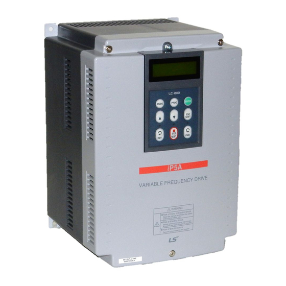
Преобразователь частоты — это силовой электронный блок, который является посредником между системой управления и электродвигателем. Он обеспечивает питание для двигателя, защищает его и задаёт необходимый режим работы — разгон, торможение или постоянное изменение скорости.
Для примера возьмем шлифовальный станок, который часто можно встретить в промышленном цеху или в столярной мастерской. Для качественной работы станка движение должно осуществляться в двух направлениях, скорость вращения ленты — меняться плавно, а аварийная кнопка мгновенно отключать питание. Без преобразователя частоты тут точно не обойтись.

Рис.1 Внешний вид шлифовального станка.
Подключение силовых цепей
Все провода, подключаемые к частотному преобразователю, можно разделить на 2 группы: силовые и контрольные. Рассмотрим подключение силовых.
Три провода сетевого питания 380 В, 50 Гц — клеммы R, S, T + провод заземления PE. Нейтраль частотному преобразователю не нужна. Даже если она у вас есть, подключать не нужно. А вот провода питания можно подключать в любом порядке. При необходимости чередование фаз можно изменить в программе частотника.
Три провода питания двигателя — клеммы U, V, W + провод заземления PE. На выходе напряжение может меняться от 0 до 380 В, а частота от 0 до 500 Гц. В этом и кроется смысл работы частотного преобразователя — он позволяет изменять скорость двигателя от нуля до номинального значения и даже выше, если это позволяет механика.

Рис.2 Подключение силовых цепей
Подключение цепей управления
С контрольными проводами всё несколько сложнее. Тут нужно хорошо подумать, прежде чем подключать. На выбор целая россыпь дискретных и аналоговых входов и выходов. В документации производители чаще всего публикуют стандартную схему подключения с заводскими настройками, но для каждого механизма на деле нужна своя схема и индивидуальные настройки.

Рис.3 Подключение цепей управления
У нас задача не самая сложная. Для управления шлифовальной машиной достаточно кнопок «Пуск», «Стоп», переключателя «Вперед – Назад» и переменного резистора для изменения скорости вращения, его ещё называют потенциометром.
К дискретным входам DI подключаются сигналы, которые могут принимать одно из двух состояний — «вкл» и «выкл» или логический 0 и 1. В нашей схеме это кнопки «Пуск», «Стоп», переключатель направления и аварийный «грибок». Мы будем использовать кнопки без фиксации, которые уже установлены на станке.
К аналоговым входам AI подключаются сигналы с непрерывно меняющейся величиной тока 4…20 мА или напряжения 0…10 В. Это могут быть датчики, сигналы от контроллера или другого внешнего устройства. В нашем случае — это ручка потенциометра, которая обеспечивает плавную регулировку скорости.
Потенциометр или переменный резистор — это регулируемый делитель напряжения с тремя контактами.

Рис.4 Внешний вид потенциометра
На два крайних неподвижных контакта подаётся постоянное напряжение 10 В от частотного преобразователя, а средний подвижный контакт служит для снятия текущей величины напряжения, которая зависит от положения ручки. Если ручка повернута наполовину, значит и напряжение будет только половинное = 5 В. Преобразователь пересчитает напряжение в задание скорости и разгонит двигатель.

Рис.5 Подключение потенциометра
Любой потенциометр не подойдёт, необходим с сопротивлением от 2 до 5 кОм, чтобы аналоговый вход стабильно работал. А ещё он должен быть с удобной ручкой, ведь крутить его придётся постоянно. Мощность может быть любой, даже 0,125 Вт достаточно. Идеально подойдёт XB5AD912R4K7 с сопротивлением 4,7 кОм.
На дискретные — DO и аналоговые выходы AO преобразователь выдает информацию о своем текущем состоянии, скорости или токе двигателя, достижении заданных значений или выходе за их пределы. В нашем случае выходы не используются, поэтому подключать нечего.
Настройка
Недостаточно просто подключить все провода к частотнику, его ещё нужно правильно настроить, чтобы механизм работал стабильно и долго. Для этого в частотном преобразователе несколько сотен параметров. Конечно, все настраивать не придётся, но вот основные — обязательно.
Настройка осуществляется с помощью клавиш на встроенной панели управления. С ними всё предельно просто.
Кнопка PRG отвечает за вход и выход из режима программирования. Кнопки вверх, вниз и вбок осуществляют навигацию внутри меню, а кнопка Enter — подтверждает выбор параметра или его значения.
MF.K — это дополнительная функциональная кнопка, которую можно настроить на необходимое действие, например переключение между местным и дистанционным управлением или смену направления вращения.
Зеленая и красная кнопки — это Пуск и Стоп, если управление осуществляется с панели.
Если запутались, не беда. Нужно несколько раз нажать на кнопку PRG, чтобы вернуться к исходному состоянию.

Рис.6 Внешний вид панели управления
А теперь к параметрированию
Во-первых, необходимо дать понять частотному преобразователю, какой двигатель к нему подключен. Для этого в параметры с F1-01 по F1-05 запишем значения с шильдика двигателя:
F1-01 = 1,5 кВт — номинальная мощность двигателя
F1-02 = 380 В — номинальное напряжение двигателя
F1-03 = 3,75 А — номинальный ток двигателя
F1-04 = 50 Гц — номинальная частота двигателя
F1-05 = 1400 об/мин — номинальная скорость двигателя

Рис.7 Шильдик двигателя
Теперь, когда основные данные о двигателе есть, нужно провести автонастройку. Этот процесс нужен, чтобы частотный преобразователь ещё лучше адаптировался к работе с конкретным двигателем: вычислил сопротивление и индуктивность обмоток. Так управление будет точнее, а экономия энергии — больше.
Для запуска процедуры устанавливаем F1-37 = 1 — статическая автонастройка и нажимаем кнопку «Run» на панели управления. Через пару минут дисплей переходит в исходное состояние и частотник готов к работе.
Далее переведём управление на внешние кнопки и настроим его
В нашем случае подойдёт трёхпроводное управление, где кнопка «Стоп» осуществляет разрешение на работу, кнопка «Старт» — запуск станка, а переключатель выбирает направление вращения.

Рис.8 Схема трёхпроводного управления
Настроим эти параметры:
F0-02 = 1 — управление через клеммы управления
F0-03 = 2 — задание частоты с AI1 (потенциометр)
F4-00 = 1 — пуск
F4-01 = 2 — выбор направления движения
F4-02 = 3 — разрешение работы
F4-03 = 47 — аварийный останов
F4-11 = 3 — режим трёхпроводного управления
Теперь станок начинает оживать, реагирует на нажатие кнопок и вращение ручки скорости. Остаётся настроить время разгона, торможения и проверить на практике удобство использования. Наш частотный преобразователь настроен и готов к использованию!
Защита и безопасность
Преобразователь частоты — умное устройство. После настройки в работу включаются все защитные функции, которые в случае аварии сберегут и сам частотник, и двигатель, и механизм.
Например, при заклинивании: преобразователь вычислит, что ток двигателя намного выше номинального, который мы установили в параметре F1-03 ранее, выдаст ошибку «Перегрузка двигателя» и отключится. Двигатель не перегреется и не сгорит, а механика останется целой.
А если возникла угроза здоровью оператора или поломки оборудования — спасет аварийная кнопка «грибок». При её нажатии преобразователь в мгновение остановит станок и отключит питание. Никто не пострадает!
Вместо заключения
Настройка частотного преобразователя — процесс увлекательный. Порой преобразователь берёт на себя не только управление двигателем, но и целой системой и может заменить даже простой контроллер. К частотнику можно подключать датчики, лампы индикации, реле и даже контакторы. Применение преобразователю можно найти везде: от насосов и конвейеров до сложных станков, подъёмников и лифтов. Главное внимательно изучать документацию и делать всё по порядку, тогда всё обязательно получится.
Ещё по теме
Настройка частотного преобразователя для регулирования давления в трубопроводе
Как настроить управление частотным преобразователем по сети Modbus
Инструкция по эксплуатации и чертежи MD310
Каталог с актуальными ценами