- Manuals
- Brands
- jcb Manuals
- Portable Generator
- G20
- Operator’s manual
-
Contents
-
Table of Contents
-
Bookmarks
Quick Links
OPERATOR’S MANUAL
GENERATOR
G20, G20QS, G20S, G27, G27QS, G27S, G33, G33QS, G33S,
G34QS, G40, G40QS, G40S, G41QS, G45, G45QS, G45S
EN — 9831/0650 ISSUE 3 — 11/2017
THIS MANUAL SHOULD ALWAYS STAY WITH THE MACHINE
Related Manuals for jcb G20
Summary of Contents for jcb G20
-
Page 1
OPERATOR’S MANUAL GENERATOR G20, G20QS, G20S, G27, G27QS, G27S, G33, G33QS, G33S, G34QS, G40, G40QS, G40S, G41QS, G45, G45QS, G45S EN — 9831/0650 ISSUE 3 — 11/2017 THIS MANUAL SHOULD ALWAYS STAY WITH THE MACHINE… -
Page 2
Operator’s Manual. You must understand and follow the instructions in the Operator’s Manual. If you do not understand anything, ask your employer or JCB dealer to explain it. OPERATOR’S Do not operate the machine without an Operator’s… -
Page 3
Notes: 9831/0650-3… -
Page 4: Table Of Contents
Table of Contents Contents Page No. Acronyms Glossary ……………………….Introduction About this Manual Model and Serial Number ……………………1 Using the Manual ……………………..1 Left-Hand Side, Right-Hand Side ………………….1 Cross References ……………………..2 Safety Safety — Yours and Others ……………………3 Safety Warnings ……………………….
-
Page 5
Table of Contents Fluids and Lubricants ……………………. 84 Maintenance Schedules General …………………………88 How to Use the Maintenance Schedules ………………. 88 Maintenance Intervals ……………………. 88 Pre-start Cold Checks, Service Points and Fluid Levels …………..88 Engine General …………………………. 91 Oil ………………………….. 91 Drive Belt ………………………. -
Page 6: Acronyms Glossary
Table of Contents Acronyms Glossary Controller Area Network Crankcase Ventilation Engine Control Module Electronic Control Unit FEAD Front End Accessory Drive High Pressure Valve Liquid Crystal Display Light Emitting Diode Product Identification Number Revolutions Per Minute Society of Automotive Engineers Universal Serial Bus 9831/0650-3…
-
Page 7
Notes: 9831/0650-3… -
Page 8: Introduction
Particular attention must be given to all the safety aspects of operating and maintaining the machine. If there is anything you are not sure about, ask your JCB dealer or employer. Do not guess, you or others could be killed or seriously injured.
-
Page 9: Cross References
Introduction About this Manual Cross References In this manual, cross references are made by presenting the subject title in blue (electronic copy only). The number of the page upon which the subject begins is indicated within the brackets. For example: Refer to: Cross References (Page 2).
-
Page 10: Safety
If you do not fully understand the warning messages, ask your employer or JCB dealer to explain them. Safety is not just a matter of responding to the warnings. All the time you are working on or with the machine you must be thinking of what hazards there might be and how to avoid them.
-
Page 11
Allow the unit to cool before completing any maintenance. Keep tools and objects away from the impeller when the unit is operating. • Use only JCB recommended parts. These parts have been designed to give the engine its optimum performance. Using spurious parts may affect the integrity of the engine. 9831/0650-3… -
Page 12: About The Product
Product Compliance Your JCB product was designed to comply with the laws and regulations applicable at the time of its manufacture for the market in which it was first sold. In many markets, laws and regulations exist that require the owner to maintain the product at a level of compliance relevant to the product when first produced.
-
Page 13: Description
About the Product Description Description Main Component Locations Figure 2. A Access door for the control panel B Access door for engine and radiator C Access panel for exhaust muffler D Access door for alternator E Access door for battery F Forklift pockets 9831/0650-3…
-
Page 14
About the Product Description Figure 3. A Fuel tank B Control panel C Emergency stop D Fuel filter/water separator E Fuel tank filler neck F Engine oil filter G Water separator H Exhaust silencer J Radiator cap K Radiator L Inlet manifold M Automatic voltage regulator N Battery P Data plate… -
Page 15
About the Product Description Figure 4. A Rocker cover B Lifting eye C Fuel injectors D Radiator cap E Radiator F Oil filler cap G High pressure pump H ECU (Electronic Control Unit) J Fuel filter/water separator K Oil filter 9831/0650-3… -
Page 16
About the Product Description Figure 5. A Oil filter cap B Air filter C Oil pressure sensor D Starter motor assembly E Fly wheel housing F Oil drain plug (sump) G Oil sump H Alternator 9831/0650-3… -
Page 17: Product And Component Identification
About the Product Product and Component Identification Product and Component Identification General The data plate details the model designation, rating, fuel type, weight, year of manufacture, output rating and other generating set specific information. The data plate is normally located on the right hand side of the alternator terminal box (looking at the alternator end of the generator).
-
Page 18
About the Product Product and Component Identification Figure 8. A Engine data label 9831/0650-3… -
Page 19: Safety Labels
Keep all of the safety labels clean and readable. Replace a lost or damaged safety label. Make sure the replacement parts include the safety labels where necessary. Each safety label has a part number printed on it, use this number to order a new safety label from your JCB dealer. 9831/0650-3…
-
Page 20: Safety Label Identification
About the Product Safety Labels Safety Label Identification Figure 9. 817/70021-2 817 /7003 2 817 /7000 5 817/70032-2 9831/0650-3…
-
Page 21
About the Product Safety Labels Table 1. Safety Labels Item Part No. Description Qty. 335/D7133 Hot surfaces. Remove the ignition key and refer to the operator’s manual and service manual. 817/70021 Noise warning. Wear ear protection. 335/D7145 Risk of electrocution. Read the operator’s manual before you operate the machine. -
Page 22: Installation And Removal
1.5m around the unit. This is for guidance only. For more detailed information contact your JCB dealer. It is also important to note that placing the unit close to solid surfaces e.g. concrete walls may cause an increase in noise and cooling problems.
-
Page 23
About the Product Installation and Removal Figure 10. A Distance from wall = 1,500mm B Air inlet C Air outlet Indoor installations Generator Set Room For the correct installation of a generator set in closed premises, the size of the room must allow: •… -
Page 24
About the Product Installation and Removal Recommended Room Dimensions Figure 11. Static Soundproof Generator Set — Side View A Generator set B Access door C Concrete base D Exhaust and hot air outlet duct E Generator length + 200mm 9831/0650-3… -
Page 25
About the Product Installation and Removal Figure 12. Static Soundproof Generator Set — Plan View A Generator set B Air inlet grill C Exhaust and hot air outlet duct D Cable Conduit E Access door F Concrete base G Generator length + 200mm H Generator width + 200mm 9831/0650-3… -
Page 26
About the Product Installation and Removal Figure 13. Canopy Delete Set — Side View A Access door B Exhaust pipe C Exhaust silencer D Hot air outlet ducts E Control panel F Concrete base G Generator set H Generator length + 200mm J Alternator The above figure shows a typical exhaust mounting arrangement. -
Page 27
About the Product Installation and Removal Figure 14. Open Generator Set- Side View A Control panel B Concrete base C Generator set D Generator over all length 9831/0650-3… -
Page 28
About the Product Installation and Removal Figure 15. Open Generator Set — Plan View A Access door B Air inlet grille C Control panel D Generator set E Hot air outlet duct F Concrete base G Cable conduit H Cable exit J Generator length + 200mm K Generator width + 200mm Basic Elements to be Considered… -
Page 29
Operating Generators in Extreme Cold Climates When the JCB Generator is operated in extreme cold climates, care must be taken to prevent the operating temperature of the engine decreasing below a level that will result in the incorrect operation of the engine components. -
Page 30
About the Product Installation and Removal Cold Start For a temperature range between 0°C (32.0°F) to -15°C (59.0°F), the standard QS canopy generator will enable the engine to crank at sufficient speed for cold starting with the standard 10w-40 engine oil. At this temperature, the grid heater is not required on the engine. -
Page 31
About the Product Installation and Removal 3. Use of incorrect fuel will cause the fuel to wax/thicken. This will block filter elements and increase wear in the fuel injection pump and injection systems. At extremely low temperatures trace heating may also be required to prevent the fuel from thickening and waxing. -
Page 32: Operation
On a busy site, use a signalman. Before doing any job not covered in this manual, find out the correct procedure. Your local JCB distributor will be glad to advise you.
-
Page 33
Operation Operating Safety Regulations Obey all laws, worksite and local regulations which affect you and your machine. Hot Components Touching hot surfaces can burn skin. The engine and machine components will be hot after the unit has been running. Allow the engine and components to cool before servicing the unit. Alcohol and Drugs It is extremely dangerous to operate machinery when under the influence of alcohol or drugs. -
Page 34: Battery Isolator
Operation Battery Isolator Battery Isolator General The battery isolator switch is used to disconnect the battery from the machine electrics. The switch must be turned to the off position if any maintenance work is to be performed on the machine. Some machine systems perform shut down cycles after the engine stops.
-
Page 35: Before Starting The Engine
• Ensure that the alternator windings and assembly are not damp, or dirty. Failure to do so could result in damage to the alternator windings. If windings are observed to be damp/dirty contact your JCB Dealer. • With the exception of emergency power generators, the engine should be warmed up with a reduced load before applying the full load.
-
Page 36: Instruments
Operation Instruments Instruments Instrument Panel Introduction Figure 18. A Digital controller B Emergency stop button C Digital controller on/off switch D Main power supply MCCB E Earth leakage relay Operation 1. Turn on the digital controller switch. 2. Wait for few seconds, to allow the controller to power up and display to stabilise. 3.
-
Page 37
Operation Instruments 11. Turn on the main power supply MCCB. 12. The generator can now be loaded. 13. If the earth leakage relay trips at this point consult the site electrical installation engineer. 14. To stop the generator, remove any electrical loads. 15. -
Page 38
Operation Instruments Figure 20. Control Push-Buttons Table 3. This button places the module into its STOP/RESET mode. This will clear any alarm conditions for which the triggering criteria have been removed. If the engine is running and the module is put into STOP mode, the module will automatically instruct the generator to unload (`Close Generator’ and `Delayed Load Output 1, 2, 3 &… -
Page 39
Operation Instruments This button will start the engine and run off load. To place the generator on load, digital inputs are required to be assigned to perform this function. If the engine is running off-load in MANUAL/START mode button and a RE- MOTE START SIGNAL becomes present, the module will automatically in- struct the changeover device to place the generator on load (`Close Gener- ator’ and `Delayed Load Output 1, 2, 3 &… -
Page 40
Operation Instruments Icons Description Flexible sender instrumentation screen Appears when the event log is being displayed Current time held in the unit The current value of the scheduler run time and duration ECU (Electronic Control Unit) diagnostic trouble codes Oil filter maintenance timers Air filter maintenance timers Fuel filter maintenance timers Active Configuration… -
Page 41
Operation Instruments Mode Icon An icon is displayed in the Mode Icon section to indicate the mode the controller is currently in. Table 7. Icons Description Appears when the engine is at rest and the unit is in stop mode. Appears when the engine is at rest and the unit is in auto mode. -
Page 42
Operation Instruments Icons Description Appears when the mains supply is available and the mains breaker is open. Appears when the mains supply is available and the mains breaker is closed. Backlight The LED backlight is on if the unit has sufficient voltage while the unit is turned on, unless the unit is cranking for which the backlight is turned off. -
Page 43
Operation Instruments Warning Alarm Icons Warnings are non-critical alarm conditions and do not affect the operation of the generator system, they serve to draw the operators attention to an undesirable condition. By default, warning alarms are self-resetting when the fault condition is removed. However enabling `all warnings are latched’ will cause warning alarms to latch until reset manually. -
Page 44
Operation Instruments Icon Fault Description Generator Over Frequency The generator output frequency has risen above the pre-set pre- alarm setting. CAN ECU Fault The engine ECU has detected an alarm. CAN (Controller Area Network) Da- The module is configured for CAN ta Fail operation and does not detect data on the engine CAN data link. -
Page 45
Operation Instruments Icon Fault Description Low Fuel Level The level detected by the fuel lev- el sensor is below the low fuel level pre-set alarm setting. High Fuel Level The level detected by the fuel level sensor is above the high fuel level pre-set alarm setting. -
Page 46
Operation Instruments Icon Fault Description Over Speed The engine speed has risen above the over speed pre alarm setting. Charge Failure The auxiliary charge alternator voltage is low as measured from the W/L terminal. Low Fuel Level The level detected by the fuel lev- el sensor is below the low fuel level pre-set alarm setting. -
Page 47
Operation Instruments Icon Fault Description Oil Filter Maintenance Alarm Maintenance due for oil filter. Air Filter Maintenance Alarm Maintenance due for air filter. Fuel Filter Maintenance Alarm Maintenance due for fuel filter. Viewing The Instrument Pages Navigation Menu To enter the navigation menu, press both the UP and DOWN buttons simultaneously. Figure 22. -
Page 48
Operation Instruments Navigation Menu Icons Table 12. Icon Description Generator and mains voltage instrumentation Generator instrumentation Mains instrumentation Current and load instrumentation Engine instrumentation Module information Engine DTCs (Diagnostic Trouble Codes) if active Event Log General Navigation It is possible to scroll through the display to view different pages of information by repeatedly operating the up or down navigation buttons, and so on until the last page is reached. -
Page 49
Operation Instruments Home This is the page that is displayed when no other page has been selected and is automatically displayed after a period of inactivity (Page Delay Timer) of the module facia buttons. It also contains the voltage reading of the generator and mains that is measured from the module’s voltage inputs. -
Page 50
Operation Instruments Load These pages contain electrical values of the load, measured or derived from the module’s voltage and current inputs. The power values displayed depend on which supply is on load. • Generator Current (A)Mains Current (A)Load ph-N (kW)Total Load (kW)Load ph-N (kVA)Total Load (kVA)Load ph-N (kVAr)Total Load (kVAr)Power Factor ph-NPower Factor AverageAccumulated Load (kWh, kVAh, kVArh) Figure 28. -
Page 51
Operation Instruments Figure 30. 13:30:00 M T W T F S 3 Wk 2:45:00 A Icon to indicate that the scheduler is B Day and week of scheduled run currently displayed C Start time of scheduled run D Duration of scheduled run Engine DTC (ECU Alarms) If the DSE module is connected to an ECU, this page contains active Diagnostic Trouble Codes (DTC) only if the engine ECU generating a fault code. -
Page 52
Operation Instruments Table 13. icon Fault DTC Description Check Engine Fault The engine ECU has detected a fault not recognised by the DSE module, contact engine manufac- turer for support. Low Oil Pressure The engine ECU has detected that the engine oil pressure has fallen below its configured low oil pres- sure alarm level. -
Page 53
Operation Instruments Figure 32. 23 h 56 m A Icon to indicate that the event log is currently B The engine hours at which the event occurred display C Current operating state of the module D Icon to indicate the electrical trip or shutdown alarm that has been recorded E Number of event displayed out Operation… -
Page 54
Operation Instruments Stopping The Engine Select STOP/RESET mode. The generator is stopped. Figure 34. B Stop/reset mode button Stop/Reset Mode If a digital input configured to panel lock is active, changing module modes will not be possible. Viewing the instruments and event logs are not affected by panel lock. STOP/RESET mode is activated by pressing the STOP/ RESET mode button. -
Page 55
Operation Instruments • Activation of an auxiliary input that has been configured to remote startActivation of the inbuilt exercise scheduler. Starting Sequence To allow for `false’ start requests, the start delay timer begins. Should all start requests be removed during the start delay timer, the unit returns to a stand-by state. If a start request is still present at the end of the start delay timer, the fuel relay is energised and the engine is cranked. -
Page 56
Operation Instruments If the unit has been configured for CAN, compatible ECU’s receives the start command via CAN. If the engine fails to fire during this cranking attempt then the starter motor is disengaged for the crank rest duration after which the next start attempt is made. Should this sequence continue beyond the set number of attempts, the start sequence is terminated and the display shows Fail to Start. -
Page 57
Operation Instruments Figure 35. When activated, the maintenance alarm can be either a warning (set continues to run) or shutdown (running the set is not possible). Resetting the maintenance alarm is normally actioned by the site service engineer after performing the required maintenance. -
Page 58
Operation Instruments Figure 37. Scheduler The controller contains an inbuilt exercise run scheduler, capable of automatically starting and stopping the set. Up to 8 scheduled start/stop sequences can be configured to repeat on a 7-day or 28-day cycle. Scheduled runs may be on load or off load depending upon module configuration. Example Figure 38. -
Page 59
Operation Instruments Depending upon configuration by the system designer, an external input can be used to inhibit a scheduled run. If the engine is running OFF LOAD in AUTO mode and a scheduled run configured to `On Load’ begins, the set is placed ON LOAD for the duration of the schedule. -
Page 60
Operation Instruments The PIN number is automatically reset when the editor is exited (manually or automatically) to ensure security. Commissioning Before the system is started, it is recommended that the following checks are made: 1. The unit is adequately cooled and all the wiring to the module is of a standard and rating compatible with the system. -
Page 61: Operating Environment
Operation Operating Environment Operating Environment General Power De-rating Figure 40. Power de-rating depending on operating air temperature above 25 degrees Celsius X Power de-rating (%) Y Air temperature (Celsius) Figure 41. Power de-rating depending on operating altitude higher than 100m above sea level. 1500 3000 1000…
-
Page 62
Operation Operating Environment Figure 42. Power de-rating depending on operating fuel temperature at injection pump inlet X Power de-rating (%) Y Fuel temperature (Celsius) Derate Table The generator output is affected by temperature and altitude. The following derate should be applied to take this into account. -
Page 63
Operation Operating Environment Altitude Ambient Temperature 2,000 2,500 3,000 3,500 4,000 4,500 5,000 Table 16. Altitude Ambient Temperature 35°C 40°C 45°C 50°C 55°C 60°C (95.0°F) (103.9°F) (112.9°F) (121.9°F) (130.9°F) (139.9°F) Sea Level 500 M 1,000 1,500 2,000 2,500 3,000 3,500 4,000 4,500 5,000… -
Page 64: Attachments
Attachments Working with Attachments Attachments Working with Attachments Attachments for your Machine Bunding Tank Figure 43. A Alternator mounting plate B Fuel bunding tank C Engine mounting plate D Bunding tank base frame E Generator AVM 9831/0650-3…
-
Page 65
Attachments Working with Attachments Fork Pockets Figure 44. A Fork pocket 9831/0650-3… -
Page 66
Attachments Working with Attachments Transportation Bracket Figure 45. A Transportation bracket B Bolts Transportation brackets is a temporary installation and must be removed after transportation. Loosen the bolts to remove all the four transportation bracket from the generator base. Refer to Figure 45. Oil Drain Valve/Pump Assembly Figure 46. -
Page 67
Attachments Working with Attachments Figure 47. A Drain pump mounting bracket B Drain pump C Hose D Drain valve 9831/0650-3… -
Page 68
Attachments Working with Attachments Oil Pressure Sensor Figure 48. A Bonded seal B Pressure transducer 9831/0650-3… -
Page 69
Attachments Working with Attachments Water Jacket Heater Figure 49. A Block heater thermostat 9831/0650-3… -
Page 70
Attachments Working with Attachments Battery Isolator Figure 50. For G20QS Only A Isolator switch B Cable (Battery negative to isolator) C Battery isolator mounting bracket D Cable (Isolator to starter motor) Figure 51. A Isolator switch B Battery isolator mounting bracket C Cable (Isolator to starter motor) D Cable (Battery negative to isolator) 9831/0650-3… -
Page 71
Attachments Working with Attachments 3 Way Fuel Valve (WFV) Figure 52. A Return line (Engine return to 3WFV) B Forward line (3WFV to lift pump inlet) C 3 way fuel valve D Return line (3WFV outlet to fuel tank) E Forward line (Fuel tank suction to 3WFV) Always refer to the direction label for the selection of internal /external tank. -
Page 72
Attachments Working with Attachments Canopy Delete Z0 Figure 54. Typical Generator A Electrical installation B Skid installation D Fuel system installation 9831/0650-3… -
Page 73
Attachments Working with Attachments CE Hot Guards Figure 55. Typical Hot Guard Plate A Mounting bracket B CE hot guard 9831/0650-3… -
Page 74
Attachments Working with Attachments ATP Panel ATP panel installation differ according to ampere requirements. Figure 56. A Control panel box B Monitoring relay C MCB stopper D Mechanical Interlock E Indicator LED (yellow) F Indicator LED (red) G Power busbar terminal H AC contactor J Voltage surge suppressor K PVC duct… -
Page 75
Attachments Working with Attachments Door Stop Arrangement Figure 58. A Position 1 B Position 2 C Door retainer bracket D Door retainer link 9831/0650-3… -
Page 76
Attachments Working with Attachments Canopy Protection Kit Figure 59. A Canopy protection block 9831/0650-3… -
Page 77
Attachments Working with Attachments Open Set Dedicated Design Figure 60. For G20QS Only A KDI B Battery installation C Fuel system installation D Generator installation E Generator F Base frame 9831/0650-3… -
Page 78
Attachments Working with Attachments Figure 61. For G27QS Only A Electrical installation B Generator installation C Fuel system installation D G drive installation E Battery installation F Base frame 9831/0650-3… -
Page 79
Attachments Working with Attachments Figure 62. For G40QS Only A Electrical installation B Alternator C Battery installation D Fuel system installation E Generator installation F Base frame 9831/0650-3… -
Page 80
Attachments Working with Attachments Figure 63. For G45QS Only A KDI B Electrical installation C Base frame D Generator installation E G drive installation F Battery installation 9831/0650-3… -
Page 81
Attachments Working with Attachments Socket Box Figure 64. A Socket box 9831/0650-3… -
Page 82
Attachments Working with Attachments Lifting Frame Single Point Figure 65. A Lifting hook B Lifting frame 9831/0650-3… -
Page 83
Attachments Working with Attachments Four Point Lifting Kit Figure 66. A Lifting hook 9831/0650-3… -
Page 84
Attachments Working with Attachments Battery Charger 27- 45kVA Figure 67. A Lead acid battery charger B 230V AC, 16A 1P44 plug 9831/0650-3… -
Page 85
Attachments Working with Attachments 20kVA Figure 68. A Lead acid battery charger B 230V AC, 16A 1P44 plug 9831/0650-3… -
Page 86
Attachments Working with Attachments Figure 69. A Current transducer B Earth leakage relay C Din rail D MCB Stopper E Earth leakage bracket 9831/0650-3… -
Page 87
Notes: 9831/0650-3… -
Page 88: Preservation And Storage
Preservation and Storage Cleaning Preservation and Storage Cleaning General 1. Stop the machine and allow it to cool for at least one hour. Do not attempt to clean any part of the machine while it is running. 2. Ensure all electrical loads are disconnected and the generator is made safe by disconnecting at the breaker, turning off the machine and activating the emergency stop switch.
-
Page 89: Maintenance Introduction General
Maintenance Introduction Maintenance Introduction General WARNING The engine has exposed rotating parts. Switch off the engine before working in the engine compartment. Do not use the machine with the engine cover open. WARNING The machine can auto-start You must isolate the engine start circuit before you start service or maintenance procedures.
-
Page 90: Maintenance Safety
Machine Modifications This machine is manufactured in compliance with prevailing legislative requirements. It must not be altered in any way which could affect or invalidate its compliance. For advice consult your JCB dealer. Repairs If your machine does not function correctly in any way, get it repaired straight away. Neglect of necessary repairs could result in an accident or affect your health.
-
Page 91: Fluids And Lubricants
If accidentally spilled on to skin, it must be washed off immediately. Protective clothing and eye protection must be worn when handling antifreeze. Hygiene JCB lubricants are not a health risk when used correctly for their intended purposes. However, excessive or prolonged skin contact can remove the natural fats from your skin, causing dryness and irritation.
-
Page 92
Maintenance Maintenance Safety The collection and disposal of used oil must be in accordance with any local regulations. Never pour used engine oil into sewers, drains or on the ground. Handling CAUTION The temperature of the hydraulic oil will be high soon after stopping the machine. Wait until it cools before beginning maintenance. -
Page 93
Maintenance Maintenance Safety Battery electrolyte contains sulphuric acid. It can burn you if it touches your skin or eyes. Wear goggles. Handle the battery carefully to prevent spillage. Keep metallic items (watches, rings, zips etc) away from the battery terminals. Such items could short the terminals and burn you. Set all switches to off before disconnecting and connecting the battery. -
Page 94
When the battery reaches the end of its usual life it must be removed from the machine and recycled in an approved way in accordance with local environmental regulations. This service is usually operated by battery vendors. Machine users that cannot find a suitable battery recycling facility should contact their JCB dealer for assistance. -
Page 95: Maintenance Schedules
Maintenance Maintenance Schedules Maintenance Schedules General A poorly maintained machine is a hazard. Doing the regular maintenance and lubrication jobs listed in these schedules will help keep the machine in safe running order. Apart from the daily jobs, the schedules are based on machine running hours. Keep a regular check on the hour meter reading.
-
Page 96
Maintenance Maintenance Schedules Component Task 1000 2000 5000 6000 Emergency stop switch- Check opera- tion Earth Leakage RCD Check opera- tion and MCB External Power Socket Check condi- tion Battery Terminals and Check voltage Control panel events Check history Bus bar cover safety Check opera- switch tion… -
Page 97
Maintenance Maintenance Schedules Component Task 1000 2000 5000 6000 Generator Alternator ca- Check condi- bles tion Generator Alternator Check tight- Terminals ness (1) If installed (2) Check seals and O-rings are in place, check covers close securely Replace if there is any sign of wear (3) In case of low use: 12 months (4) The period of time that must elapse before checking the filter element depends on the environment in which the engine operates. -
Page 98: Engine
Maintenance Engine Engine General Clean Notice: Clean the engine before you start engine maintenance. Obey the correct procedures. Contamination of the fuel system will cause damage and possible failure of the engine. Notice: The engine or certain components could be damaged by high pressure washing systems; special precautions must be taken if the engine is to be washed using a high pressure system.
-
Page 99
Maintenance Engine 2. Wait for the oil to drain back into the engine sump before you take a reading. If not, a false low reading may be recorded which can cause the engine to be overfilled. 3. Get access to the engine. 4. -
Page 100: Drive Belt
2. Let the engine cool. 3. Remove the FEAD (Front End Accessory Drive) belt cover. 4. Check the belt condition, if worn out or deteriorated contact your JCB dealer for any service requirements. 5. Check the belt tension. Figure 71.
-
Page 101
To reconnect from a star to delta connection (for e.g. from 400V to 230V), modify the linking arrangements on the output terminal board. It is not necessary to adjust the voltage regulator. These alterations must be carried out by a suitably qualified and competent person. Consult you JCB dealer. Figure 73. Connecting Lugs 9831/0650-3… -
Page 102
Maintenance Engine Standard alternators are equipped with 12 cables to offer different voltages (e.g. 230/400/460/800V). The alternator must always be earthed by sufficiently rated cable, using one of the inside or outside terminals. For the electrical connections, use wires suitable for the power of the generator and connect them to the terminal board. -
Page 103
Maintenance Engine • Parameters: Volt, Stab, Amp and Hz can be set with trimmers (default) 50/60Hz through a jumper (default). All parameters can be programmed via software • Analogical remote control of output voltage is possible through external voltage (0 to 2, 5V DC) or with a 10 kohm linear potentiometer •… -
Page 104
Maintenance Engine L A.P.O M Alaram LED N 50/60 P Memory Q Serial communication interface R Vext S Sensing T Voltage output V Vmin W Power supply An error in connection may have serious consequences for the unit. Carefully check to make sure that all connections are precise and in accordance with the attached drawings, before turning on the power. -
Page 105
Maintenance Engine Figure 77. Regulator Setup Selection of the sensing scale takes place directly according to the connection on the power terminal board; additional settings can be made with 4 trimmers (VOLT, STAB, AMP and Hz) and 3 jumpers (50/60Hz, JP1 and JP2). -
Page 106
Maintenance Engine Alarms During normal operation and a duty cycle of 50%, an indicator light mounted on the board flashes every two seconds. It flashes differently in the event of intervention or alarm. Figure 78. A Stop B Amp and (Hz or O.S.) C Hz or O.S. -
Page 107
Maintenance Engine Regulators Figure 79. REG TYPE SO7- 2G V Voltage The generator output must be checked under no load conditions, with the correct setting of frequency. The voltage may be adjusted by +/- 5% of the nominal, by acting upon the voltage potentiometer on the electronic regulators. -
Page 108
Maintenance Engine When using the machine in single phase, or for voltages different from the one pre-set at the factory, recalibration of the AMP and STAB potentiometers could be necessary. Intervention of Protection Devices Causes Underspeed Protection Instantaneous Intervention • Speed reduced by 10% of nominal RPM (Revolutions Per Minute). -
Page 109
Maintenance Engine Maintenance operations can be divided into routine and extraordinary maintenance operations. In both cases, all operations must be authorised by the safety representative and they must be carried out when the machine is turned off and insulated from the electric installation or from the power mains. High qualified mechanical or electrical technicians must carry out maintenance operations and any fault search since all operations described hereunder could put personnel in serious danger. -
Page 110: Air Filter
Maintenance Air Filter Air Filter General Check (Condition) 1. Make the machine safe. 2. Get access to the air filter. 3. Check the system hoses for: 3.1. Condition. 3.2. Damage. 3.3. Security. 4. Replace the system hoses if necessary. Replace Do not attempt to wash or clean the elements, they must only be renewed.
-
Page 111: Dust Valve
Maintenance Air Filter Dust Valve Check (Condition) • Check the dust valve for rips/tears. • Check there are no obstructions. • Check that the dust valve is free of dirt and dust. • Check that the dust valve securely attached to the air filter housing. 9831/0650-3…
-
Page 112: Fuel System
B Fuel lift pump Check (Leaks) 1. Make the machine safe. 2. Get access to the engine compartment (if applicable). 3. Check the engine compartment (if applicable), fuel lines and the area below for leaks. 4. If necessary, contact your JCB dealer. 9831/0650-3…
-
Page 113: Engine Fuel Filter
Maintenance Fuel System Engine Fuel Filter Replace 1. Make the machine safe. 2. Get access to the engine compartment 3. Remove the sensor housing. 4. Unscrew and remove the filter element. 5. Fit a new element. Lubricate the gasket of the new cartridge. Do not fill the new cartridge with fuel. 6.
-
Page 114
Maintenance Fuel System Figure 86. A Tap B Bowl Figure 87. A Water separator B Maximum level (red line) C Drain plug 9831/0650-3… -
Page 115: Cooling System
Maintenance Cooling System Cooling System Coolant Check (Level) CAUTION The cooling system is pressurised when the coolant is hot. When you remove the cap, hot coolant can spray out and burn you. Make sure that the engine is cool before you work on the cooling system. 1.
-
Page 116
Maintenance Cooling System 3. Get access to the radiator. 4. Check the condition of the coolant hoses. 5. Check the radiator and intercooler surfaces for signs of damage. 6. If necessary, contact your JCB dealer for any service requirements. 9831/0650-3… -
Page 117: Electrical System
Maintenance Electrical System Electrical System General Check (Condition) Batteries Batteries used in normal temperate climate applications should not need topping up. In certain conditions (such as prolonged operation in high ambient temperatures or if the alternator overcharges) the electrolyte level should be checked frequently and topped up as necessary.
-
Page 118
Maintenance Electrical System Figure 88. 4. Apply a thin layer of petroleum jelly to the terminal posts. Connect The batteries leads will require connecting on initial installation. When connecting the single battery to the machine, always connect the positive terminal first followed by the negative terminal. -
Page 119
Maintenance Electrical System Figure 91. A Cover B Nut C Cable 1 D Handle E Cable 2 F Clamp 1. Make the machine safe. 2. Use the handles to put the battery into its compartment. 3. Connect the cable 1 and the cable 2. 4. -
Page 120
Maintenance Electrical System Battery Cable Installation Figure 92. A Rubber boot 1. Make sure to cover the battery connection with the rubber boot. 2. Lug should not bend, crack or stress during installation. 3. Make sure that lug should not touch to any conducting part. Disconnect CAUTION This component is heavy. -
Page 121
Maintenance Electrical System Figure 94. Twin Battery 12V Machines — Parallel Connection (Example) A Battery B Positive lead C Battery link lead D Negative lead Figure 95. 24 Volt Machines — Series Connection (Example) A Battery B Positive lead C Battery link lead D Negative lead 9831/0650-3… -
Page 122
Maintenance Electrical System Figure 96. A Cover B Nut C Cable 1 D Handle E Cable 2 F Clamp 1. Make the machine safe. 2. Get access to the battery or batteries (depending on the specification of your machine). 3. If installed, move the battery isolator switch to the off position and then remove the key. 4. -
Page 123
The control panel, remote communication (if installed) and other stand-by functions, provide some drain on the battery. JCB recommend that wherever possible an onboard battery charger is fitted. This charger will provide a maintenance charge to the system batteries allowing for optimum system performance whenever start-up signal is received. -
Page 124
Maintenance Electrical System Where it is not possible to have an onboard battery charger installed, JCB recommend a running cycle of 1– 2h twice weekly. This exercising of the Generator Set recuperates the battery utilizing the charging alternator, and allows the machine to maintain a healthy stand-by state. -
Page 125
Maintenance Electrical System 6. If the tests are unsatisfactory, refer to the fault diagnosis table. Table 20. Fault Diagnosis Battery Tester Readings Remedy Check Load 0–12.6V Less than 6V Renew battery 6–12.4V less than 9V and decreases steadi- Recharge and re-test. If tests are ly but remains in yellow zone still unsatisfactory renew battery Less than 10V… -
Page 126: Fault-Finding
Maintenance Fault-Finding Fault-Finding General The fault finding procedures are given in the form of flow charts. There are a number of charts, each one dedicated to a particular fault category. The charts are designed to identify possible causes by performing checks and where applicable, specific tests on the engine.
-
Page 127
Maintenance Fault-Finding Air intake system blocked or restricted. Visually check the air intake for blockage or obstruc- tion — remove as required. Check the air filter ele- ments for signs of blocking — replace as required. Fuel is aerated. Check the fuel system for loose connections and possible air ingress points. -
Page 128
Maintenance Fault-Finding Fuel lift pump not operating correctly (fuel supply in- Check that the lift pump is operating and delivering adequate). fuel to the injection pump. Fuel is waxing due to extremely cold weather. Verify by inspecting the fuel filter. Clean the system and use acclimatised fuel. -
Page 129
Maintenance Fault-Finding Table 27. Engine — Poor Running at Idle Cause Remedy Coolant temperature sensor fault Check the electrical connection at the coolant sen- sor. Check the correct electrical wires for open or short circuits. test the coolant sensor. If engine will not reach operating temperature refer to the following table. -
Page 130
Maintenance Fault-Finding Fuel is contaminated or incorrect grade diesel fuel Stop the engine. used. Replace the fuel filters. Operate the engine with a temporary supply of the correct grade of clean fuel. Note: Dirty fuel will cause damage to the fuel injec- tion pump and injectors. -
Page 131
Maintenance Fault-Finding Fuel injection lines leaking. Inspect and correct as required leaks in the high pressure lines, fittings injector sealing washers, or delivery valves. WARNING: Fine jets of fluid at high pressure can penetrate the skin. Keep face and hands well clear of pressurised fluid and wear protective glasses. -
Page 132
Maintenance Fault-Finding One or more fuel injector worn or malfunctioning. Check the electrical connections at the injectors. Worn or malfunctioning high pressure fuel pump. Do all the necessary fault finding checks before re- moval of the high pressure fuel pump. Table 32. -
Page 133
Maintenance Fault-Finding Turbocharger wastegate faulty. (Turbocharged ma- Repair or replace wastegate. chines only). Turbocharger malfunction. Replace Turbocharger. Electrical sensor fault. Check the electrical connections at the sensors. One or more fuel injector worn or malfunctioning. Check the electrical connections at the injectors. Engine compression low in one or more cylinders. -
Page 134
Maintenance Fault-Finding WARNING: Fine jets of fluid at high pressure can penetrate the skin. Keep face and hands well clear of pressurised fluid and wear protective glasses. If fluid penetrates your skin, get medical help immediately. Intake air or exhaust leaks. Refer to Table 34. -
Page 135
Maintenance Fault-Finding Lubricating oil sludge excessive. Change oil and filter. Review oil and filter change period. If operating in ar- duous applications, change more frequently. Make sure the correct lubricating oil is being used. Fuel in the lubricating oil, engine operating too cold. Review the operation for excessive idling resulting in the engine running below normal temperature. -
Page 136
Maintenance Fault-Finding Lubricating oil cooler leak. Check/replace the oil cooler. Look for coolant in the oil. Cylinder head gasket leak. Check/replace the head gasket. Cylinder head cracked or porous. Check/replace the head. Cylinder block coolant passages leaking. Check/replace the cylinder block. Table 44. -
Page 137
Maintenance Fault-Finding Table 46. Coolant — Contaminated Cause Remedy Coolant rusty, operation without correct mixture of Drain and flush the cooling system. Fill with correct antifreeze and water. mixture of antifreeze and water. Review the coolant change interval. Refer to the Op- eration and Maintenance Manual. -
Page 138
Maintenance Fault-Finding Sensor connection faulty Check the condition of sensor to harness connection, make sure the seals are in place, check for signs of corrosion or con- tamination. Repair/replace as necessary. If no fault is found, proceed to Step 3. Sensor failure Check the sensor resistance (see relevant helpfile page). -
Page 139
Maintenance Fault-Finding If the electrical resistance is OK, replace the rail and HPV. If no fault is found proceed to step 4. HPV buzzing fault Perform the HPV buzz test. If the HPV is not buzzing replace the rail and HPV. If the HPV buzzes, raise Techweb Helpdesk call. -
Page 140
Maintenance Fault-Finding Injector connection fault Check the Individual Injector Corrections and injector connec- tions. If the problem with C3I or injector connection is evident, replace/repair as necessary. If no fault is found proceed to step 3. Engine Cylinder compression Run the compression test (automatic or manual), if any of the fault engine cylinder pressure is not in the limits, repair/replace as necessary. -
Page 141
Maintenance Fault-Finding Sensor failure Check the sensor resistance (see relevant helpfile page). If sensor is out of specification replace. If no faults is found, proceed to Step 4. Wiring fault Check the harness continuity and machine and engine earth contacts. Repair/ replace as necessary. If no fault found, raise Techweb Helpdesk call. -
Page 142
Maintenance Fault-Finding If no faults is found, proceed to Step 4. Sensor signals faulty Check the sensor signals. If scope available, display Cam and crank signals on the scope. Change the sensor as necessary. If no fault is found, proceed to Step 5. Sensor target wheel fault Check the Cam target wheel if damaged, replace with new camshaft. -
Page 143
Maintenance Fault-Finding Table 65. Open Circuit Injector Step Trouble Action/Remedy Pressure diagnostics fault Perform the injector buzz test, if the injector is faulty it will not produce a buzzing sound. In such instances raise Techweb Helpdesk call. If no fault is found proceed to step 2. Injector connection fault Check the resistance of injector. -
Page 144
Maintenance Fault-Finding Check the operating temperature is not above 70°C (157.9°F) Check the DC fuse Fail to Start is activated after pre-set number of at- Check the wiring of fuel solenoid. tempts to start Check the fuel Check the battery supply Check the battery supply is present on the fuel output of the module Check the speed-sensing signal is present on the… -
Page 145
Maintenance Fault-Finding Alarms Table 69. Symptom Possible Remedy Low oil pressure fault operates after engine has fired Check the engine oil pressure. Check the oil pressure switch/sensor and wiring. Check configured polarity (if applicable) is correct (i.e. normally open or normally closed) or that sensor is compatible with the module and is correctly config- ured. -
Page 146
Maintenance Fault-Finding Check that the CTs are wired correctly with regards to the direction of current flow (p1,p2 and s1,s2) and additionally ensure that CTs are connected to the correct phase (errors will occur if CT1 is connected to phase 2). Remember to consider the power factor (kW = kVA x powerfactor). -
Page 147
Notes: 9831/0650-3… -
Page 148: Technical Data
Technical Data Introduction Technical Data Introduction General Table 73. Model Gererator Set rating Engine Type Serial Number (Stand by) 20 kVA KDI 1903M From 2288985 to 2298985 G20S 20 kVA KDI 1903M From 2288985 to 2298985 G20QS 20 kVA KDI 1903M From 2288985 to 2298985 27 kVA KDI 2504M…
-
Page 149: Static Dimensions
Technical Data Static Dimensions Static Dimensions Dimensions Table 74. Model Length (mm) Width (mm) Height (mm) Shipping Vol- ume (sea ready) (m3) 1,750mm 750mm 1,350mm 1.78m³ G20S 1,650mm 650mm 1,200mm 1.3m³ G20QS 1,750mm 790mm 1,350mm 1.88m³ 2,250mm 800mm 1,350mm 2.43m³ G27S 1,650mm 650mm…
-
Page 150: Noise Emissions
Technical Data Noise Emissions Noise Emissions Noise Data Table 76. Description G20QS G27QS G33QS G34QS G40QS G41QS G45QS LpA (7m) 60 dB(A) 62 dB(A) 62 dB(A) 62 dB(A) 62 dB(A) 62 dB(A) 62 dB(A) 9831/0650-3…
-
Page 151: Fluids, Lubricants And Capacities
10W-40 5-W40 Recommended Oils Table 78. Engine Oil Specification JCB Extreme Performance API CI — 4, CH — 4, CG — 4 ACEA E4 ACEA E5 ACEA E7 (1) High performance (Euro 1 — 2 — 3 Engines) heavy duty…
-
Page 152: Fuel
Technical Data Fluids, Lubricants and Capacities Fuel WARNING Do not use petrol in this machine. Do not mix petrol with the diesel fuel. In storage tanks the petrol will form flammable vapours. Notice: No warranty liability will be accepted for engine failures where unacceptable fuel grades (or their equivalent) have been used at any stage.
-
Page 153: Coolant
The correct concentration of antifreeze protects the engine against frost damage in winter and provides year round protection against corrosion. The protection provided by JCB High Performance Antifreeze and Inhibitor is shown below. Table 81. Concentration…
-
Page 154: Electrical System
Technical Data Electrical System Electrical System General Table 82. Description G20/G20S/ G27/G27S/ G33/G33S/ G34QS G40/G40S/ G41QS G45/G45S/ G20QS G27QS G33QS G40QS G45QS Frequency Hz 50/60 50/60 50/60 50/60 50/60 50/60 50/60 Phases Rated Speed 1500/1800 1500/1800 1500/1800 1500/1800 1500/1800 1500/1800 1500/1800…
-
Page 155: Schematic Circuit
Technical Data Electrical System Schematic Circuit Figure 98. 335/F5093-3 (sheet 1 of 6) 9831/0650-3…
-
Page 156
Technical Data Electrical System Figure 99. 335/F5093-3 (sheet 2 of 6) 9831/0650-3… -
Page 157
Technical Data Electrical System Figure 100. 335/F5093-3 (sheet 3 of 6) 9831/0650-3… -
Page 158
Technical Data Electrical System Figure 101. 335/F5093-3 (sheet 4 of 6) 9831/0650-3… -
Page 159
Technical Data Electrical System Figure 102. 335/F5093-3 (sheet 5 of 6) 9831/0650-3… -
Page 160
Technical Data Electrical System Figure 103. 335/F5093-3 (sheet 6 of 6) 9831/0650-3… -
Page 161
Technical Data Electrical System Figure 104. 336/E4738-B (sheet 1 of 7) 9831/0650-3… -
Page 162
Technical Data Electrical System Figure 105. 336/E4738-B (sheet 2 of 7) 9831/0650-3… -
Page 163
Technical Data Electrical System Figure 106. 336/E4738-B (sheet 3 of 7) 9831/0650-3… -
Page 164
Technical Data Electrical System Figure 107. 336/E4738-B (sheet 4 of 7) 9831/0650-3… -
Page 165
Technical Data Electrical System Figure 108. 336/E4738-B (sheet 5 of 7) 9831/0650-3… -
Page 166
Technical Data Electrical System Figure 109. 336/E4738-B (sheet 6 of 7) 9831/0650-3… -
Page 167
Technical Data Electrical System Figure 110. 336/E4738-B (sheet 7 of 7) 9831/0650-3… -
Page 168
Technical Data Electrical System Figure 111. 336/E5832-1 (sheet 1 of 7) 9831/0650-3… -
Page 169
Technical Data Electrical System Figure 112. 336/E5832-1 (sheet 2 of 7) 9831/0650-3… -
Page 170
Technical Data Electrical System Figure 113. 336/E5832-1 (sheet 3 of 7) 9831/0650-3… -
Page 171
Technical Data Electrical System Figure 114. 336/E5832-1 (sheet 4 of 7) 9831/0650-3… -
Page 172
Technical Data Electrical System Figure 115. 336/E5832-1 (sheet 5 of 7) 9831/0650-3… -
Page 173
Technical Data Electrical System Figure 116. 336/E5832-1 (sheet 6 of 7) 9831/0650-3… -
Page 174
Technical Data Electrical System Figure 117. 336/E5832-1 (sheet 7 of 7) 9831/0650-3… -
Page 175: Engine
Technical Data Engine Engine General Table 83. Description G20/G20S/ G27/G27S/ G33/G33S/ G34QS G40/G40S/ G41QS G45/G45S/ G20QS G27QS G33QS G40QS G45QS Output Rating 17.5 23.1 33.1 33.1 37.3 (PRP) kW @ 1500 RPM Output Rating 19.25 25.41 36.41 36.41 41.03 (Standby) kW @…
-
Page 176
Technical Data Engine Description G20/G20S/ G27/G27S/ G33/G33S/ G34QS G40/G40S/ G41QS G45/G45S/ G20QS G27QS G33QS G40QS G45QS Starting System Starter Motor (kW) 9831/0650-3… -
Page 177: Warranty Information
The following warranty terms and conditions are applicable, for further details please contact your JCB dealer: • – 18 months from date of despatch from JCB or 12 months from first date in service (whichever is earlier). • – Cross-hire, consequential damage and third party losses are not warrantable.
Основная мощность
100.00 кВт
Резервная мощность
110.00 кВт
Частота выдаваемой электроэнергии
50.00 Гц
Количество фаз / напряжение
3/400 В
Модель двигателя
JCB 448 G-TCA-115
Диаметр и ход поршня
106×135.00 мм
Емкость масляной системы
14.00 л
Емкость системы охлаждения
18.00 л
Расход топлива при нагрузке 50%
16.00 л/ч
Расход топлива при нагрузке 100%
29.60 л/ч
Расход топлива при нагрузке 110%
32.70 л/ч
Емкость основного топливного бака
270.00 л
Габаритные размеры (ДхШхВ)
2850 x 1140 x 1850 мм
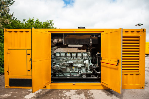
ДПромышленный дизельный генератор JCB G140QS номинальной мощностью 100,0 кВт предназначен для питания потребителей переменным трехфазным электрическим током напряжением 230/400 В с частотой 50 Гц. Устройство может использоваться как в основном режиме, например для нужд стройплощадок, так и в качестве резервного источника питания, на промышленном объекте, или в офисных зданиях. Уже в стандартной комплектации генератор оснащен электрическим подогревателем охлаждающей жидкости и устройством автоматической подзарядки аккумуляторных батарей от сети 220 В.
В качестве двигателя используется четырехцилиндровый JCB DIESELMAX, который также используется на семействе экскаваторов-погрузчиков JCB 3CX, JCB 4CX и JCB 5CX. Двигатель JCB DIESELMAX отличается высокими показателями надежности и долговечности, а также простотой в обслуживании и доступностью комплектующих благодаря своей распространенности. Двигатель JCB DISELMAX изготовлен по строгим европейским нормам и стандартам, в связи с чем отличается не только высокими показателями эффективности, но и экологически дружелюбен.
Генератор JCB можно располагать вне спициального помещения, так как устройство поставляется в шумозащитном кожухе, в комплекте с глушителем для работы в жилых зонах. Это делает возможным его применение не только на стройках и объектах промышленного характера, но и в местах с высокими требованиями к санитарным нормам, таких, как больницы, санатории или гостиницы. Кожух генератора оснащен подъемной петлей, благодаря которой упрощается задача его перемещения.
Комплектация
- Дизельный двигатель с механическим регулятором оборотов
- Промышленный альтернатор с автоматическим регулятором напряжения
- Панель управления с ЖК дисплеем на русском языке
- Цельносварная рама с виброопорами и сплошным днищем для защиты от протекания технических жидкостей
- Съемный топливный бак, встроенный в раму генератора
- Шумозащитный кожух с широкими распашными дверями, упрощающими обслуживание генератора
- Глушитель для работы в жилых зонах
- Кнопка аварийного останова станции на внешней стороне кожуха
- Силовой автоматический выключатель

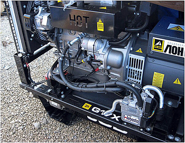
Бандажный подогреватель топливного фильтра
Бандажный подогреватель топливного фильтра позволяет избежать явления парафинизации дизельного топлива в фильтре при эксплуатации генератора в холодное время года
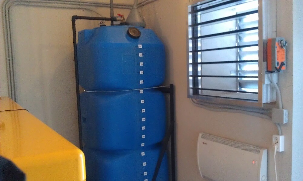
Дополнительное топливохранилище
Дополнительный топливный бак с системой автоподачи топлива в расходный бак позволяет увеличить период автономной работы станции. Топливные баки могут поставляться комплектно с контейнерами, а также в отдельных кожухах, отвечающих всем требованиям по пожарной безопасности
Низкошумный глушитель
Дополнительный глушитель для ДГУ позволяет уменьшить уровень звукового загрязнения на 25-30 дБ

Система удаленного мониторинга
Комплекс обродувания и программного обеспечения, который позваляет отслеживать состояние основных характеристик генератора, его место положение, предупредительные и аварийные сигналы, а также осуществлять удаленное управление через сеть интернет
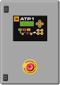
Шкаф АВР
Модуль автоматического ввода резерва в пыле- и влагозащищенном шкафу (опционально), который позволяет в автоматическом режиме запустить генератор и переключить потребителей на питание от генератора с минимально возможной задержкой
Другие варианты исполнения
В контейнере
ДГУ в контейнере надежно защищена от неблагоприятных погодных условий и взлома. Внутри контейнера размещены все необходимые системы для безопасной работы и комфортного обслуживания ДГУ.
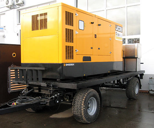
Передвижное
Передвижная ДГУ может быть выполнена в различных исполнениях, на шасси тракторного, или автомобильного типа (в кожухе, или контейнере), на салазках, или в кунге грузового автомобиля.
Вы здесь
Перейти к полной версии/Вернуться
сб, 11.03.2023 — 21:48
#1
Регистрация: 23.07.2021 — 03:25
10
Не в сети
Заходил: 1 неделя 3 дня назад
Дизель-электрогенератор молчит с сообщением об ошибке «Не сделано техобслуживание» (или как-то так): кто имеет опыт — чё с этим делать? В обход компьютера мотор запускается, — масло есть, топливо есть, — всё-класс. Инструкции нет. Как обычно с такими генераторами проводится техобслуживание, а именно — какого компьютер заругался — и откуда он узнает — что мы «пыль протёрли»? — мож-ему просто сброс какой-то сделать? — поделитесь опытом.

Оставьте заявку онлайн
Наша компания обеспечивает своевременное и качественное техническое обслуживание и ремонт дизельных генераторов JCB G140QS как в нашей сервисной зоне, так и с выездом по всей России.
Дизельная электростания JCB G140QS предназначена для стационарного размещения и может устанавливаться как в помещении (открытая комплектация, кожух), так и на улице (кожух, контейнер).

Технические характеристики дизельного генератора JCB G140QS:
| Модель | G140QS |
| Максимальная мощность, (кВт) | 112.2 |
| Мощность, (кВт) | 101 |
| Напряжение, (В) | 230/400 |
| Количество фаз, (Ф) | 3 |
| Запуск | электростартер |
| Исполнение | в кожухе |
| Вид топлива | дизель |
| Функция сварки | Нет |
| Частота, (Гц) | 50 |
| Тип генератора | Синхронный |
| Расход топлива, (л/ч) | 22.4 |
| Емкость топливного бака, (л.) | 285 |
| Двигатель | JCB |
| Система охлаждение двигателя | жидкостная |
| Частота вращения двигателя, (об/мин) | 1500 |
| Вес, (кг) | 1720 |
| Габариты (ДхШхВ), (мм) | 2850x1140x1830 |
| Страна | Великобритания |
| Производители | JCB |
Возможные неисправности дизельного генератора JCB G140QS:
- Дизельный двигатель не запускается.
- Нет 230/400 вольт. Отсутствует выходное напряжение.
- Двигатель запускается и глохнет.
- Дизельный двигатель останавливается, глохнет спустя интервал времени.
- Двигатель глохнет под нагрузкой запитанных электропотребителей.
- Двигатель не развивает свою мощность (не выходит на заданные рабочие обороты).
- Расход масла выше обычного.
- Громкий стук во время работы.
- Черный, бело-голубой цвет выхлопа.
- Высокий расход топлива.
- Напряжение ниже 230/400 вольт.
- Напряжение значительно выше 230/400 вольт.
- Напряжение около 20 вольт.
- Частота не соответствует 50 Гц.
- Чёрный выхлоп отработанных газов.
- Сизый выхлоп отработанных газов.
- Стартер не вращается, туго вращается.
- Электрический стартер не срабатывает.
- Потеки масла на корпусе двигателя (запотевание).
- Течь топлива.
- Посторонний шум при работе двигателя.
- Хлопки из глушителя при работе.
- Запах гари при работающем дизельгенераторе.
- Конденсатор лопнул, вздулся его корпус.
- Перегорела обмотки статора.
- Перегорела обмотки ротора.
Список ремонтируемых моделей JCB:
- JCB G13QX
- JCB G20QS
- JCB G27QS
- JCB G33QS
- JCB G45QS
- JCB G65QS
- JCB G90QS
- JCB G115QS
- JCB G140QS
- JCB G165QS
- JCB G220QS
- JCB G275S
- JCB G275QS
- JCB G275BVO5
- JCB G275QBVO5
- JCB G350S
- JCB G350QS
- JCB G350BVO5
- JCB G350QBVO5
- JCB G415S
- JCB G415QS
- JCB G415BVO5
- JCB G415QBVO5
- JCB G440S
- JCB G440QS
- JCB G440BVO5
- JCB G440QBVO5
- JCB G495BVO5
- JCB G495QBVO5
- JCB G500S
- JCB G500QS
- JCB G550S
- JCB G550QS
- JCB G550BVO5
- JCB G550QBVO5
- JCB G660S
- JCB G660QS
- JCB G660BVO5
- JCB G660QBVO5
- JCB G700S
- JCB G700BVO5
- JCB G700QS
- JCB G700SCU5
- JCB G700QBVO5
- JCB G800SPE5
- JCB G850SPE5
- JCB G850SCU5
- JCB G850SMI5
- JCB G1000SPE5
- JCB G1000SCU5
- JCB G1005SCU5
- JCB G1100SMI5
- JCB G1100SCU5
- JCB G1100SPE5
- JCB G1105SCU5
- JCB G1240SPE5
- JCB G1380SPE5
- JCB G1400SMI5
- JCB G1410SCU5
- JCB G1480SPE5
- JCB G1530SMI5
- JCB G1540SCU5
- JCB G1600SPE5
- JCB G1650SPE5
- JCB G1650SMI5
- JCB G1650SCU5
- JCB G1700SCU5
- JCB G1900SMI5
- JCB G2000SCU5
- JCB G2000SPE5
- JCB G2090SMI5
- JCB G2200SMI5
- JCB G2250SCU5
- JCB G2250SPE5
- JCB G2500SCU5
- JCB G2500SPE5
- JCB G2500SMI5
Наши весомые преимущества
по ремонту дизель-генераторов JCB G140QS:
- 17 лет ремонтируем и обслуживаем
- Нагрузочное тестирование дизельных генераторов. В наличии нагрузочные стенды суммарной мощностью более 2 мвт.
- Электролабаратория. У нас есть собственная электролабаратория со всем необходимым оборудованием, с помощью которого мы выполняем:
- ремонт регулятора напряжения;
- ремонт блока управления дизельным двигателем;
- ремонт панели управления;
- ремонт контроллера;
- Компьютерная диагностика
- Станок для ремонта ДВС
- Видеоэндоскопия. Без демонтажа ГБЦ мы можем посмотреть состояние цилиндро-поршневой группы.
- Отличные условия для приема: сами разгружаем и погружаем. Есть погрузчик и кран-балка, вы можете приезти генератор на обычной бортовой машине, не нужен манипулятор.
- 4 выездные машины, укомплектованные всем необходимым оборудованием и первоклассными специалистами
- А также:
- доставка по всей россии
- гарантия на запчасти и услуги
- большой склад запчастей
Цены на ремонт дизельных генераторов JCB G140QS
| Вид работ | Стоимость, рублей |
|---|---|
| Диагностика дизельного генератора JCB G140QS | |
| Диагностика дизельного генератора JCB G140QS в цеху | по запросу |
| Выезд | по запросу |
| Доставка техники | по запросу |
| Ремонт ДГУ JCB G140QS | |
| Ремонт системы отвода картерных газов | по запросу |
| Регулировка блока АВР | по запросу |
| Замена avr | по запросу |
| Замена топливного фильтра | по запросу |
| Ремонт топливной системы | по запросу |
| Ремонт и перемотка силового альтернатора | по запросу |
| Замена воздушного фильтра | по запросу |
| Ремонт системы впуска | по запросу |
| Замена соленоида | по запросу |
| Замена радиатора охлаждающей жидкости | по запросу |
| Замена контроллера управления | по запросу |
| Ремонт системы охлаждения | по запросу |
| Прошивка блока управления | по запросу |
| Ремонт и замена АВР (блока автоматики) | по запросу |
| Регулировка форсунок | по запросу |
| Регулировка форсунок | по запросу |
| Техническое обслуживание дизельных генераторов JCB G140QS | |
| ТО 1-ой категории (замена масла, проверка эл.цепей) | по запросу |
| ТО 2-ой категории (ТО 1 + замена воздушного фильтра) | по запросу |
| ТО 3-й категории (ТО 2 + замена масляного и топливного фильтра) | по запросу |
Внимание!
Конечная цена зависит от множества факторов и определяется только после диагностики ДГУ, более точную цену Вы можете узнать, оставив заявку на ремонт.
В среднем диагностика ДЭС JCB G140QS занимает несколько часов.
Работаем по всей России!
Выезжаем в любой район Москвы и Московской области, а также в любой регион России!
Мы — официальный сервисный центр JCB
С 2011 года являемся официальным авторизованным сервисным цетром марки JCB, уполномочены осуществлять продажу и производить гарантийное и послегарантийное обслуживание техники фирмы-производителя. Даём гарантию на ремонтные работы и запчасти!
Заявка на ремонт дизельного генератора JCB G140QS
Пожалуйста, заполните форму ниже для более точного расчета цены на ремонт
JCB Product Support Laptop Based Diagnostic Tool Manual Download
JCB Diagnostic Trouble Codes Download
JCB flash codes list Download
JCB JS-Excavator’s Fault Codes List Download
JCB v8+ Electrical Error Fault codes v1-07 Download
Troubleshooting/fault code,error kode JCB Excavator JS 200 JS 210 JS 220 JS 240 JS 260 Download
Livelink is a monitoring system that allows you to check the condition of equipment from anywhere in the world.
A special adapter connects to the equipment and transmits data to the JCB site via satellites and the cellular network, so that at any time, wherever you are, you can go to the site and find out
the current state of the observed JCB equipment.
In the GENERAL category, you can view help information, DLA adapter settings, Servicemaster program manual, as well as additional programs for diagnostics of
engines, transmissions and hydrostatic systems of such machines as FASTRAC T4 tractors, TELETRUK LPG loaders, Loadall 532H-537H telehandlers.
In order to start diagnostics or other procedures, you need to select the type of equipment from the corresponding category.
And then select the desired procedure from the available ones. For most types of equipment, in addition to diagnostics, you can configure the blocks, download new firmware and updates, view the
service history, decode error codes, do various tests, detailed help is also available in which you can see the location of components and wiring diagrams.
Please note that the list of available options for different types and models of equipment is different!
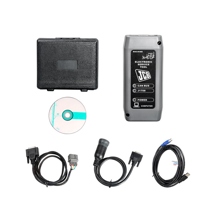
JCB Diagnostic Kit (DLA) is a multifunctional dealer scanner that reads diagnostic trouble codes, ranking them according to the degree of need for service on JCB equipment.
Main functional features:
reads fault codes and ranks them in order of importance.
calibrates, parameters and programs ECM units.
carries out a reset of service intervals.
Compatible with Jcb Service Master 2 software.
works with CAN protocol in OBD II system.
supplied with instructions for operation, repair and diagnostics of JCB equipment and engines Isuzu, Deutz, Cummins.
JCB Diagnostic Kit (DLA) Applicability
JCB agricultural machinery
Fastrac tractors (2000-3000, 3000 2 Series, 3000 Series 3, 7000-Series, 8250-Series 1, 8250 3 Series, 8000-Series 3).
Telescopic handlers (2007 -, 2007 +).
Wheeled backhoe loaders (Large, Large 2012+, Compact).
JC construction machinery
Backhoe loaders, tracked excavators (JS / JZ, JZ70).
Wheeled excavators, compact excavators (Mini / Midi) (801-8065, 8080-8085).
Telescopic handlers (2007 -, 2007 +).
Skidsteer loaders (Robot and others).
Telescopic handlers Teletrucks.
Wheeled backhoe loaders (Large, Large 2012+, Compact).
Frontal loaders.
Vibrating rollers.
Rough terrain forklifts.
JCB engines
JCB Dieselmax (MPS, OEM Base, G Drive).
JCB Ecomax (MPS, OEM Base, G Drive).
Equipment
JCB Diagnostic Kit (DLA) scanner.
USB cable.
DB9 cable.
9-pin adapter for German equipment.
8-pin cable.
JCB ServiceMaster 2 v10.3.1 software.
JCB Compact Service Manuals v50 [2011] (S1, S2, S3, S4, S5).
|
Tracked & Wheeled Excavators |
Extracted fromVersion 145 |
No of Error Codes in list 978 |
|
J1939 |
In Use? |
Reviewed/ |
Diagnostic Trouble |
Machine Reaction |
Extended Fault Text (Datalogger/Diagnostic Tools) |
|
0x00 |
Y |
55 |
P0001 |
Torque Reduction |
IMV driver fault is detected |
|
0x00 |
Y |
55 |
P0002 |
Torque Reduction |
Rail Pressure Negative Control Error During ‘IMV-Only’ control. PID controller not able to stabilise the |
|
0x00 |
Y |
55 |
P0002 |
Torque Reduction |
Rail pressure control error (pressure error too high). |
|
0x00 |
Y |
55 |
P0002 |
Delayed Engine Stop |
Rail Pressure Positive Control Error During ‘IMV-Only’ control. PID controller not able to stabilise the |
|
0x00 |
Y |
55 |
P0002 |
Torque Reduction |
Rail pressure control error (pressure error too low). |
|
0x00 |
Y |
55 |
P0003 |
Rail pressure control feedback low error |
|
|
0x00 |
Y |
55 |
P0003 |
Torque Reduction |
IMV driver fault is detected |
|
0x00 |
Y |
55 |
P0004 |
Torque Reduction |
IMV driver fault is detected |
|
0x00 |
Y |
55 |
P0004 |
Torque Reduction |
Rail pressure control feedback high error |
|
0x00 |
Y |
124 |
P0016 |
Cam Sensor Phase Shift |
|
|
0x00 |
Y |
124 |
P0045 |
VNT Control Fault |
|
|
0x00 |
Y |
124 |
P0045 |
Turbo EVRV Fault |
|
|
0x3D |
Y |
114 |
P0070-81 |
CAN bus message error from engine ECU |
|
|
0x3D |
Y |
114 |
P0070-87 |
CAN bus message error from engine ECU |
|
|
0x3D |
Y |
114 |
P0071-87 |
CAN bus message error for environment temperature from engine ECU |
|
|
0x00 |
Y |
55 |
P007A |
Torque Reduction |
TMAP (Intake Manifold 1 temp) Temperature Element sensor fault (ADC) |
|
0x00 |
Y |
55 |
P007C |
Torque Reduction |
TMAP (Intake Manifold 1 temp) Temperature Element sensor low fault |
|
0x00 |
Y |
55 |
P007D |
Torque Reduction |
TMAP (Intake Manifold 1 temp) Temperature Element sensor high fault |
|
0x00 |
Y |
55 |
P007E |
Torque Reduction |
TMAP (Intake Manifold 1 temp) Temperature Element sensor noise fault |
|
0x00 |
Y |
114 |
P0087 |
Torque Reduction |
Rail Pressure Control Error Positive |
|
0x00 |
Y |
55 |
P0087 |
Rail Pressure build low fault |
|
|
0x00 |
Y |
114 |
P0087 |
Rail Pressure build normal fault |
|
|
0x00 |
Y |
114 |
P0087 |
Torque Reduction_Delayed Engine Stop |
RPC Variable Limit Capacity (VLC) Torque reduction clamped |
|
0x00 |
Y |
124 |
P0087 |
Torque Reduction_Delayed Engine Stop |
Pressure Limiter Open |
|
0x00 |
Y |
114 |
P0087 |
Torque Reduction |
RPC Variable Limit Capacity (VLC) Torque reduction above its threshold |
|
0x00 |
Y |
114 |
P0088 |
Torque Reduction |
Rail pressure control error during HPV control (over max calibrated system pressure) |
|
0x00 |
Y |
114 |
P0088 |
Torque Reduction |
Rail pressure control error during IMV control (over max calibrated system pressure) |
|
0x00 |
Y |
55 |
P0088 |
Torque Reduction |
Rail pressure control undefined error (over max calibrated system pressure) |
|
0x00 |
Y |
114 |
P0088 |
Rail Pressure Control Error Negative |
|
|
0x00 |
Y |
124 |
P0088 |
Torque Reduction |
C/Rail pressure exceeds hi upper limit3 |
|
0x00 |
Y |
114 |
P0088 |
Rail Pressure overpressure timeout |
|
|
0x00 |
Y |
124 |
P0088 |
Torque Reduction |
Common Rail Pressure Rise㸦 1st Stage㸧 |
|
0x00 |
Y |
114 |
P0089 |
Rail Pressure control error |
|
|
0x00 |
Y |
114 |
P0089 |
Rail Pressure Negative Control Error During ‘HPV-Only’ control. PID controller not able to stabilise the |
|
0x00 |
Y |
114 |
P0089 |
Rail Pressure Positive Control Error During ‘HPV-Only’ control. PID controller not able to stabilise the |
|
|
0x00 |
Y |
55 |
P0089 |
Rail Pressure Negative Control Error During ‘IC & HMV’ control. PID controller not able to stabilise the |
|
|
0x00 |
Y |
114 |
P0089 |
Rail Pressure Positive Control Error During ‘IC & HMV’ control. PID controller not able to stabilise the |
|
|
0x00 |
Y |
114 |
P0089 |
Torque Reduction |
Rail Pressure Negative Control Error During ‘RVD-Only’ control. PID controller not able to stabilise the |
|
0x00 |
Y |
114 |
P0089 |
Delayed Engine Stop |
Rail Pressure Positive Control Error During ‘RVD-Only’ control. PID controller not able to stabilise the |
|
0x00 |
Y |
114 |
P0089 |
Torque Reduction |
Check that HPV is not stuck during IMV regulation. |
|
0x00 |
Y |
114 |
P0089 |
Torque Reduction |
HPV open loop slope fault detected |
|
0x00 |
Y |
124 |
P0089 |
Common Rail Pressure Fault (Excess Feed) |
|
|
0x00 |
Y |
55 |
P0090 |
Torque Reduction |
HPV driver in ECU fault detected |
|
0x00 |
Y |
55 |
P0091 |
Torque Reduction |
Check HPV regulation control trim low |
|
0x00 |
Y |
114 |
P0091 |
Torque Reduction |
Check HPV hardware current control trim low |
|
0x00 |
Y |
114 |
P0091 |
Torque Reduction |
HPV current feedback low fault detected |
|
0x00 |
Y |
124 |
P0091 |
Torque Reduction |
SCV Low Voltage Fault |
|
0x00 |
Y |
114 |
P0091 |
Torque Reduction |
HPV driver in ECU fault detected |
|
0x00 |
Y |
55 |
P0092 |
Torque Reduction |
Check HPV regulation control trim high. |
|
0x00 |
Y |
124 |
P0092 |
Torque Reduction_Delayed Engine Stop |
SCV High Voltage Fault |
|
0x00 |
Y |
114 |
P0092 |
Torque Reduction |
Check HPV hardware current control trim high |
|
0x00 |
Y |
114 |
P0092 |
Torque Reduction_Delayed Engine Stop |
HPV current feedback high fault detected |
|
0x00 |
Y |
114 |
P0092 |
Torque Reduction_Delayed Engine Stop |
HPV driver in ECU fault detected |
|
0x00 |
Y |
124 |
P0093 |
Common Rail Pressure Fall (No Feed) |
|
|
0x00 |
Y |
124 |
P0093 |
Common Rail Pressure Fault (Lack of Feed 2) |
|
|
0x00 |
Y |
55 |
P0095 |
Torque Reduction |
Intake manifold temperature (M2) signal sensor ADC fault (Intake Manifold 2 temp) |
|
0x00 |
Y |
55 |
P0096 |
Torque Reduction |
Intake manifold temperature sensor (M2) signal noise fault (Intake Manifold 2 temp) |
|
0x00 |
Y |
55 |
P0096 |
Torque Reduction |
Intake manifold temperature sensor (M2) signal plausibility fault (Intake Manifold 2 temp) |
|
0x00 |
Y |
55 |
P0097 |
Torque Reduction |
Intake manifold temperature sensor (M2) signal low fault (Intake Manifold 2 temp) |
|
0x00 |
Y |
55 |
P0098 |
Torque Reduction |
Intake manifold temperature sensor (M2) signal high signal fault (Intake Manifold 2 temp) |
|
0x3D |
Y |
114 |
P00B7-87 |
T4F Inducement |
CAN bus message error for coolant sensor from engine ECU |
|
0x00 |
Y |
55 |
P0100 |
Torque Reduction |
AMF High Side Driver fault Short Circuit To Ground (SC2G) |
|
0x00 |
Y |
114 |
P0100 |
Torque Reduction |
AMF fault (global). Set if plau, grad or electrical flt is present |
|
0x00 |
Y |
114 |
P0100 |
Torque Reduction |
AMF High Side Driver fault (Global |
|
0x00 |
Y |
114 |
P0100 |
Torque Reduction |
AMF High Side Driver fault Open Circuit (OC) Or Short Circuit to Battery (SC2VBAT) |
|
0x00 |
Y |
114 |
P0100 |
Torque Reduction |
AMF High Side Driver fault Short Circuit (SC) |
|
0x00 |
Y |
114 |
P0100 |
Torque Reduction |
AMF electrical sensor fault (ADC) |
|
0x00 |
Y |
124 |
P0101 |
MAF Sensor Fault |
|
|
0x00 |
Y |
124 |
P0102 |
Torque Reduction |
MAF Low Voltage Fault |
|
0x00 |
Y |
55 |
P0102 |
Torque Reduction |
AMF electrical sensor low fault |
|
0x00 |
Y |
124 |
P0103 |
Torque Reduction |
MAF High Voltage Fault |
|
0x00 |
Y |
55 |
P0103 |
Torque Reduction |
AMF electrical sensor high fault |
|
0x00 |
Y |
55 |
P0105 |
Torque Reduction |
Intake Manifold Absolute Pressure (MAP) sensor global fault |
|
0x00 |
Y |
55 |
P0106 |
Torque Reduction |
Intake Manifold Absolute Pressure (MAP) sensor signal drift low fault |
|
0x00 |
Y |
55 |
P0106 |
Torque Reduction |
Intake Manifold Absolute Pressure (MAP) sensor signal drift high fault |
|
0x00 |
Y |
55 |
P0106 |
Torque Reduction |
Intake Manifold Absolute Pressure (MAP) sensor signal plausibility fault |
|
0x00 |
Y |
55 |
P0106 |
Torque Reduction |
Intake Manifold Absolute Pressure (MAP) sensor signal plausibility high fault |
|
0x00 |
Y |
55 |
P0106 |
Torque Reduction |
Intake Manifold Absolute Pressure (MAP) sensor signal plausibility low fault |
|
0x00 |
Y |
124 |
P0107 |
Boost Pressure Sensor Fault 㸦 Low Voltage Fault |
|
|
0x00 |
Y |
124 |
P0108 |
Boost Pressure Sensor Fault 㸦 High Voltage Fault㸧 |
|
|
0x00 |
Y |
55 |
P0110 |
Torque Reduction |
Inlet Air Temperature (IAT) sensor signal ADC fault detected |
|
0x00 |
Y |
124 |
P0112 |
Torque Reduction |
Inlet Air Temperature (IAT) sensor signal low fault detected |
|
0x00 |
Y |
124 |
P0113 |
Torque Reduction |
Inlet Air Temperature (IAT) sensor signal high fault detected |
|
0x00 |
Y |
55 |
P0115 |
Torque Reduction |
Coolant sensor signal fault |
|
0x00 |
Y |
55 |
P0116 |
Coolant sensor fault (plausibility) |
|
|
0x00 |
Y |
124 |
P0116 |
Torque Reduction |
Coolant temperature sensor performance invalid |
|
0x00 |
Y |
55 |
P0117 |
Coolant sensor signal low fault |
|
|
0x00 |
Y |
124 |
P0117 |
Coolant temperature sensor signal too low |
|
|
0x00 |
Y |
124 |
P0118 |
Coolant sensor signal high fault |
|
|
0x00 |
Y |
124 |
P0122 |
Intake Throttle Position Low Voltage Fault |
|
|
0x00 |
Y |
124 |
P0123 |
Intake Throttle Position High Voltage Fault |
|
|
0x3D |
Y |
114 |
P0129-87 |
Erroneous signal for Barometric Pressure. |
|
|
0x3D |
Y |
114 |
P0129-87 |
CAN bus message error for environment pressure from engine ECU |
|
|
0x00 |
Y |
55 |
P0133 |
Wide Range Air Fuel control (WRAF) fault: Response |
|
|
0x00 |
Y |
55 |
P0180 |
Torque Reduction |
Fuel temperature ADC fault |
|
J1939 |
In Use? |
Added |
Diagnostic Trouble |
Machine Reaction |
Extended Fault Text (Datalogger/Diagnostic Tools) |
|
0x00 |
Y |
124 |
P0181 |
Torque Reduction |
Fuel Temperature Sensor Fault |
|
0x00 |
Y |
55 |
P0181 |
Torque Reduction |
Fuel temperature sensor gradient fault |
|
0x3D |
Y |
114 |
P0181-87 |
CAN bus message error for fuel temperature from engine ECU |
|
|
0x00 |
Y |
124 |
P0182 |
Torque Reduction |
Fuel temperature sensor low fault |
|
0x00 |
Y |
124 |
P0183 |
Torque Reduction |
Fuel temperature sensor high fault |
|
0x00 |
Y |
55 |
P0190 |
Torque Reduction_Limp Home (Idle Only) |
Rail Pressure Sensor signal grad fault |
|
0x00 |
Y |
55 |
P0191 |
Torque Reduction_Limp Home (Idle Only) |
Rail Pressure Sensor fault. Above maximum threshold (out of range at key-on) |
|
0x00 |
Y |
55 |
P0191 |
Torque Reduction_Limp Home (Idle Only) |
Rail Pressure Sensor fault. Below minimum threshold (out of range at key-on) |
|
0x00 |
Y |
55 |
P0191 |
Torque Reduction_Limp Home (Idle Only) |
Rail Pressure Sensor fault. Exceeds threshold (out of range at key-on) |
|
0x00 |
Y |
124 |
P0192 |
Torque Reduction_Limp Home (Idle Only) |
Rail Pressure Sensor signal low fault |
|
0x00 |
Y |
124 |
P0193 |
Torque Reduction_Limp Home (Idle Only) |
Rail Pressure Sensor signal high fault |
|
0x00 |
Y |
55 |
P0194 |
Torque Reduction_Limp Home (Idle Only)_Delayed |
Rail Pressure Sensor signal drop fault |
|
0x00 |
Y |
55 |
P0195 |
Torque Reduction |
Oil temperature sensor signal global fault |
|
0x00 |
Y |
114 |
P0195 |
Torque Reduction |
Oil temperature sensor signal external voltage (V-Ref) fault |
|
0x00 |
Y |
55 |
P0196 |
Torque Reduction |
Oil temperature sensor signal plausability fault |
|
0x00 |
Y |
55 |
P0196 |
Torque Reduction |
Oil temperature sensor signal gradient fault |
|
0x3D |
Y |
114 |
P0196-87 |
CAN bus message error for oil temperature from engine ECU |
|
|
0x00 |
Y |
55 |
P0197 |
Torque Reduction |
Oil temperature sensor signal low fault |
|
0x00 |
Y |
55 |
P0198 |
Torque Reduction |
Oil temperature sensor signal high fault |
|
0x00 |
Y |
55 |
P0201 |
Injector 2 Open Circuit fault (OC) |
|
|
0x00 |
Y |
55 |
P0201 |
Injector in Cylinder 1 Short Circuit HSD to LSD |
|
|
0x00 |
Y |
124 |
P0201 |
Injector in Cylinder 1 Open Circuit fault (OC) |
|
|
0x00 |
Y |
124 |
P0202 |
Injector 1 Open Circuit fault (OC) |
|
|
0x00 |
Y |
55 |
P0202 |
Injector in Cylinder 2 Short Circuit HSD to LSD |
|
|
0x00 |
Y |
88 |
P0202 |
Injector in Cylinder 2 Open Circuit fault (OC) |
|
|
0x00 |
Y |
124 |
P0203 |
Injector 3 Open Circuit fault (OC) |
|
|
0x00 |
Y |
55 |
P0203 |
Injector in Cylinder 3 Short Circuit HSD to LSD |
|
|
0x00 |
Y |
88 |
P0203 |
Injector in Cylinder 3 Open Circuit fault (OC) |
|
|
0x00 |
Y |
124 |
P0204 |
Injector 0 Open Circuit fault (OC) |
|
|
0x00 |
Y |
55 |
P0204 |
Injector in Cylinder 4 Short Circuit HSD to LSD |
|
|
0x00 |
Y |
88 |
P0204 |
Injector in Cylinder 4 Open Circuit fault (OC) |
|
|
0x00 |
Y |
124 |
P0205 |
Injector in Cylinder 5 Open Circuit fault (OC) |
|
|
0x00 |
Y |
88 |
P0205 |
Injector in Cylinder 5 Short Circuit HSD to LSD |
|
|
0x00 |
Y |
124 |
P0206 |
Injector in Cylinder 6 Open Circuit fault (OC) |
|
|
0x00 |
Y |
88 |
P0206 |
Injector in Cylinder 6 Short Circuit HSD to LSD |
|
|
0x00 |
Y |
124 |
P0217 |
Torque Reduction |
Coolant temperature exceeds upper limit |
|
0x00 |
Y |
124 |
P0219 |
Torque Reduction |
Engine overspeed condition |
|
0x00 |
Y |
124 |
P0234 |
Torque Reduction |
Turbo Over Boost |
|
0x00 |
Y |
55 |
P0235 |
Torque Reduction |
Boosted air pressure sensor fault: ADC |
|
0x00 |
Y |
55 |
P0237 |
Torque Reduction |
Boosted air pressure sensor low fault |
|
0x00 |
Y |
55 |
P0238 |
Torque Reduction |
Boosted air pressure sensor high fault |
|
0x00 |
Y |
55 |
P0252 |
Torque Reduction |
Rail pressure control error (IMV current trim drift). |
|
0x00 |
Y |
114 |
P0252 |
Torque Reduction |
Rail pressure control error (IMV current trim drift). |
|
0x00 |
Y |
114 |
P0252 |
Torque Reduction |
Rail pressure control error (IMV current trim drift). |
|
0x00 |
Y |
114 |
P0252 |
Torque Reduction |
Rail pressure control error (IMV current trim drift). |
|
0x00 |
Y |
114 |
P0252 |
Torque Reduction |
Rail pressure control error (IMV current trim drift). |
|
0x00 |
Y |
55 |
P0253 |
Torque Reduction_Delayed Engine Stop |
Rail pressure control by the IMV. Occurs at high fuel delivery for low (negative) current trim |
|
0x00 |
Y |
55 |
P0254 |
Torque Reduction_Delayed Engine Stop |
Rail pressure control fault by the IMV. Occurs at high fuel delivery for high (positive) current trim |
|
0x00 |
Y |
55 |
P0261 |
Torque Reduction |
Injector and wiring harness resistance too high/low (inj 2) |
|
0x00 |
Y |
55 |
P0261 |
Torque Reduction |
Injector and wiring harness resistance too high/low (inj 2) |
|
0x00 |
Y |
55 |
P0262 |
Torque Reduction |
Injector and wiring harness resistance drop (Inj 2) |
|
0x00 |
Y |
55 |
P0262 |
Torque Reduction |
Injector and wiring harness resistance drop (Inj 2) |
|
0x00 |
Y |
55 |
P0263 |
Torque Reduction |
Cylinder balancing fault injector 2 stuck closed |
|
0x00 |
Y |
55 |
P0264 |
Torque Reduction |
Injector and wiring harness resistance too high/low (inj 1) |
|
0x00 |
Y |
55 |
P0264 |
Torque Reduction |
Injector and wiring harness resistance too high/low (inj 1) |
|
0x00 |
Y |
55 |
P0265 |
Torque Reduction |
Injector and wiring harness resistance drop (Inj 1) |
|
0x00 |
Y |
55 |
P0265 |
Torque Reduction |
Injector and wiring harness resistance drop (Inj 1) |
|
0x00 |
Y |
55 |
P0266 |
Torque Reduction |
Cylinder balancing fault injector 1 stuck closed |
|
0x00 |
Y |
55 |
P0267 |
Torque Reduction |
Injector and wiring harness resistance too high/low (inj 3) |
|
0x00 |
Y |
55 |
P0267 |
Torque Reduction |
Injector and wiring harness resistance too high/low (inj 3) |
|
0x00 |
Y |
55 |
P0268 |
Torque Reduction |
Injector and wiring harness resistance drop (Inj 3) |
|
0x00 |
Y |
55 |
P0268 |
Torque Reduction |
Injector and wiring harness resistance drop (Inj 3) |
|
0x00 |
Y |
55 |
P0269 |
Torque Reduction |
Cylinder balancing fault injector 3 stuck closed |
|
0x00 |
Y |
55 |
P0270 |
Torque Reduction |
Injector drift fault detection on Injector 2. Fault which is set when the Injector 2 MDP trim exceeds the |
|
0x00 |
Y |
55 |
P0270 |
Torque Reduction |
Injector drift fault detection on Injector 2. Fault which is set when Injector 2 MDP trim exceeds the |
|
0x00 |
Y |
55 |
P0271 |
Torque Reduction |
Injector and wiring harness resistance drop (Inj 0) |
|
0x00 |
Y |
55 |
P0271 |
Torque Reduction |
Injector and wiring harness resistance drop (Inj 0) |
|
0x00 |
Y |
55 |
P0272 |
Torque Reduction |
Cylinder balancing fault injector 0 stuck closed |
|
0x00 |
Y |
88 |
P0273 |
Injector and wiring harness resistance too high/low (inj 1) |
|
|
0x00 |
Y |
88 |
P0273 |
Injector and wiring harness resistance too high/low (inj 1) |
|
|
0x00 |
Y |
88 |
P0274 |
Injector and wiring harness resistance drop (Inj 1) |
|
|
0x00 |
Y |
88 |
P0274 |
Injector and wiring harness resistance drop (Inj 1) |
|
|
0x00 |
Y |
88 |
P0275 |
Cylinder balancing fault injector 1 stuck closed |
|
|
0x00 |
Y |
88 |
P0276 |
Injector and wiring harness resistance too high/low (inj 3) |
|
|
0x00 |
Y |
88 |
P0276 |
Injector and wiring harness resistance too high/low (inj 3) |
|
|
0x00 |
Y |
88 |
P0277 |
Injector and wiring harness resistance drop (Inj 3) |
|
|
0x00 |
Y |
88 |
P0277 |
Injector and wiring harness resistance drop (Inj 3) |
|
|
0x00 |
Y |
88 |
P0278 |
Cylinder balancing fault injector 3 stuck closed |
|
|
0x00 |
Y |
124 |
P0299 |
Torque Reduction |
Turbo Low Boost |
|
0x00 |
Y |
55 |
P029A |
Injector drift fault detection on Injector 3. Fault which is set when the Injector 3 MDP trim exceeds the |
|
|
0x00 |
Y |
55 |
P029A |
Injector drift fault detection on Injector 2. Fault which is set when the Injector 2 MDP trim exceeds the |
|
|
0x00 |
Y |
55 |
P029A |
Injector drift fault detection on Injector 2. Fault which is set when Injector 2 MDP trim exceeds the |
|
|
0x00 |
Y |
55 |
P029B |
Fault which is set when the Injector 3 absolute MDP value is below a calibrated threshold |
|
|
0x00 |
Y |
55 |
P029B |
Injector drift fault detection on Injector 2. Fault which is set when Injector 2 MDP trim exceeds the |
|
|
0x00 |
Y |
55 |
P029B |
Injector drift fault detection on Injector 2. Fault which is set when Injector 2 MDP trim exceeds the |
|
|
0x00 |
Y |
55 |
P029B |
Injector drift fault detection on Injector 2. Fault which is set when Injector 2 MDP trim exceeds the |
|
J1939 |
In Use? |
Added |
Diagnostic Trouble |
Machine Reaction |
Extended Fault Text (Datalogger/Diagnostic Tools) |
|
0x00 |
Y |
55 |
P029E |
Injector drift fault detection on Injector 1. Fault which is set when the Injector 1 MDP trim exceeds the |
|
|
0x00 |
Y |
55 |
P029E |
Injector drift fault detection on Injector 1. Fault which is set when the Injector 1 MDP trim exceeds the |
|
|
0x00 |
Y |
55 |
P029E |
Injector drift fault detection on Injector 1. Fault which is set when Injector 1 MDP trim exceeds the |
|
|
0x00 |
Y |
55 |
P029F |
Fault which is set when the Injector 2 absolute MDP value is below a calibrated threshold |
|
|
0x00 |
Y |
55 |
P029F |
Injector drift fault detection on Injector 1. Fault which is set when Injector 1 MDP trim exceeds the |
|
|
0x00 |
Y |
55 |
P029F |
Injector drift fault detection on Injector 1. Fault which is set when Injector 1 MDP trim exceeds the |
|
|
0x00 |
Y |
55 |
P029F |
Injector drift fault detection on Injector 1. Fault which is set when Injector 1 MDP trim exceeds the |
|
|
0x00 |
Y |
55 |
P02A2 |
Injector drift fault detection on Injector 2. Fault which is set when the Injector 2 MDP trim exceeds the |
|
|
0x00 |
Y |
55 |
P02A2 |
Injector drift fault detection on Injector 2. Fault which is set when the Injector 2 MDP trim exceeds the |
|
|
0x00 |
Y |
55 |
P02A2 |
Injector drift fault detection on Injector 2. Fault which is set when Injector 2 MDP trim exceeds the |
|
|
0x00 |
Y |
55 |
P02A3 |
Fault which is set when the Injector 4 absolute MDP value is below a calibrated threshold |
|
|
0x00 |
Y |
55 |
P02A3 |
Injector drift fault detection on Injector 3. Fault which is set when Injector 3 MDP trim exceeds the |
|
|
0x00 |
Y |
55 |
P02A3 |
Injector drift fault detection on Injector 3. Fault which is set when Injector 3 MDP trim exceeds the |
|
|
0x00 |
Y |
55 |
P02A3 |
Injector drift fault detection on Injector 3. Fault which is set when Injector 3 MDP trim exceeds the |
|
|
0x00 |
Y |
55 |
P02A6 |
Injector drift fault detection on Injector 0. Fault which is set when the Injector 0 MDP trim exceeds the |
|
|
0x00 |
Y |
55 |
P02A6 |
Injector drift fault detection on Injector 0. Fault which is set when the Injector 0 MDP trim exceeds the |
|
|
0x00 |
Y |
55 |
P02A6 |
Injector drift fault detection on Injector 0. Fault which is set when Injector 0 MDP trim exceeds the |
|
|
0x00 |
Y |
55 |
P02A7 |
Fault which is set when the Injector 1 absolute MDP value is below a calibrated threshold |
|
|
0x00 |
Y |
55 |
P02A7 |
Injector drift fault detection on Injector 0. Fault which is set when Injector 0 MDP trim exceeds the |
|
|
0x00 |
Y |
55 |
P02A7 |
Injector drift fault detection on Injector 0. Fault which is set when Injector 0 MDP trim exceeds the |
|
|
0x00 |
Y |
55 |
P02A7 |
Injector drift fault detection on Injector 0. Fault which is set when Injector 0 MDP trim exceeds the |
|
|
0x00 |
Y |
88 |
P02AA |
Injector drift fault detection on Injector 1. Fault which is set when the Injector 1 MDP trim exceeds the |
|
|
0x00 |
Y |
88 |
P02AA |
Injector drift fault detection on Injector 1. Fault which is set when the Injector 1 MDP trim exceeds the |
|
|
0x00 |
Y |
88 |
P02AA |
Injector drift fault detection on Injector 1. Fault which is set when Injector 1 MDP trim exceeds the |
|
|
0x00 |
Y |
88 |
P02AB |
Fault which is set when the Injector 1 absolute MDP value is below a calibrated threshold |
|
|
0x00 |
Y |
88 |
P02AB |
Injector drift fault detection on Injector 1. Fault which is set when Injector 1 MDP trim exceeds the |
|
|
0x00 |
Y |
88 |
P02AB |
Injector drift fault detection on Injector 1. Fault which is set when Injector 1 MDP trim exceeds the |
|
|
0x00 |
Y |
88 |
P02AB |
Injector drift fault detection on Injector 1. Fault which is set when Injector 1 MDP trim exceeds the |
|
|
0x00 |
Y |
88 |
P02AE |
Injector drift fault detection on Injector 3. Fault which is set when the Injector 3 MDP trim exceeds the |
|
|
0x00 |
Y |
88 |
P02AE |
Injector drift fault detection on Injector 3. Fault which is set when the Injector 3 MDP trim exceeds the |
|
|
0x00 |
Y |
88 |
P02AE |
Injector drift fault detection on Injector 3. Fault which is set when Injector 3 MDP trim exceeds the |
|
|
0x00 |
Y |
88 |
P02AF |
Fault which is set when the Injector 3 absolute MDP value is below a calibrated threshold |
|
|
0x00 |
Y |
88 |
P02AF |
Injector drift fault detection on Injector 3. Fault which is set when Injector 3 MDP trim exceeds the |
|
|
0x00 |
Y |
88 |
P02AF |
Injector drift fault detection on Injector 3. Fault which is set when Injector 3 MDP trim exceeds the |
|
|
0x00 |
Y |
88 |
P02AF |
Injector drift fault detection on Injector 3. Fault which is set when Injector 3 MDP trim exceeds the |
|
|
0x3D |
Y |
114 |
P0321-87 |
CAN bus message error for engine speed from engine ECU |
|
|
0x00 |
Y |
55 |
P0325 |
Accelerometer fault (signal/noise ratio too low in idle) |
|
|
0x00 |
Y |
94 |
P0330 |
Knock Sensor 1 Circuit |
|
|
0x00 |
Y |
124 |
P0335 |
Crank Sensor Fault 㸦 No Signal㸧 |
|
|
0x00 |
Y |
55 |
P0335 |
Crankshaft Position Sensor «A» Circuit |
|
|
0x00 |
Y |
114 |
P0335 |
Crank signal overspeed fault |
|
|
0x00 |
Y |
124 |
P0336 |
Torque Reduction |
Crank Sensor Fault 㸦 Signal Fault㸧 |
|
0x00 |
Y |
55 |
P0340 |
Torque Reduction |
Cam signal last learnt value is outside of limits |
|
0x00 |
Y |
124 |
P0340 |
Torque Reduction |
G Sensor Fault (No Signal) |
|
0x00 |
Y |
55 |
P0341 |
Torque Reduction |
Cam signal drift higher than threshold |
|
0x00 |
Y |
124 |
P0341 |
Torque Reduction |
G Sensor Fault (Abnormal Signal㸧 |
|
0x00 |
Y |
55 |
P0341 |
Camshaft Position Sensor A Circuit Range / Performance |
|
|
0x00 |
Y |
55 |
P0341 |
Torque Reduction |
Cam signal lost (no Cam signal seen in 2 Crank rotations) |
|
0x00 |
Y |
55 |
P0341 |
Torque Reduction |
Cam signal fault (missing event within the expected window) |
|
0x00 |
Y |
55 |
P0341 |
Cam signal fault (overspeed detected) |
|
|
0x3D |
Y |
114 |
P0350-02 |
Error monitoring for system protection based on ignition switch input |
|
|
0x00 |
Y |
55 |
P0371 |
Torque Reduction |
Crank signal is too close to the previous one |
|
0x00 |
Y |
55 |
P0372 |
Torque Reduction |
Elapsed time between CPS events is too high |
|
0x00 |
Y |
55 |
P0374 |
Torque Reduction |
Crank signal lost (no CPS signal seen in 1 Cam rotation) |
|
0x00 |
Y |
124 |
P0380 |
Glow Plug/Heater Circuit «A» |
|
|
0x00 |
Y |
55 |
P0380 |
Glow Plug/Heater Circuit «A» |
|
|
0x00 |
Y |
124 |
P0381 |
Glow Plug Fault |
|
|
0x00 |
Y |
55 |
P0383 |
Glow Plug Control Module Control Circuit Low |
|
|
0x00 |
Y |
55 |
P0384 |
Glow Plug Control Module Control Circuit High |
|
|
0x00 |
Y |
55 |
P0400 |
Torque Reduction / T4F Inducement |
EGR flow reached its limit |
|
0x00 |
Y |
124 |
P0401 |
EGR Gas flow Fault |
|
|
0x00 |
Y |
124 |
P0404 |
EGR Valve Control Fault |
|
|
0x00 |
Y |
124 |
P0404 |
EGR Open Defective |
|
|
0x00 |
Y |
94 |
P0404 |
Exhaust Gas Recirculation «A» Control Circuit Range/Performance |
|
|
0x00 |
Y |
55 |
P0405 |
Exhaust Gas Recirculation Sensor «A» Circuit Low |
|
|
0x00 |
Y |
55 |
P0406 |
Exhaust Gas Recirculation Sensor «A» Circuit High |
|
|
0x00 |
Y |
124 |
P0409 |
EGR Position Sensor Fault 㸦 Brushless Specification㸧 |
|
|
0x00 |
Y |
124 |
P041C |
Manifold Temperature Sensor Fault 㸦 High Voltage |
|
|
0x00 |
Y |
124 |
P041D |
Manifold Temperature Sensor Fault 㸦 Low Voltage Fault㸧 |
|
|
0x00 |
Y |
124 |
P0426 |
DPF Exhaust Temperature 1 High |
|
|
0x00 |
Y |
124 |
P0426 |
DPF Exhaust Temperature 1Low |
|
|
0x00 |
Y |
124 |
P0427 |
Exhaust Temperature Sensor 1Low Voltage Fault |
|
|
0x00 |
Y |
124 |
P0428 |
Exhaust Temperature Sensor 1High Voltage Fault |
|
|
0x00 |
Y |
124 |
P042B |
DPF Exhaust Temperature 2 High |
|
|
0x00 |
Y |
124 |
P042B |
DPF Exhaust Temperature 2 Low |
|
|
0x00 |
Y |
124 |
P042C |
Exhaust Temperature Sensor 2 Low Voltage Fault |
|
|
0x00 |
Y |
124 |
P042D |
Exhaust Temperature Sensor 2 High Voltage Fault |
|
|
0x00 |
Y |
94 |
P046D |
Exhaust Gas Recirculation Sensor «A» Circuit Intermittent/Erratic |
|
|
0x00 |
Y |
55 |
P0470 |
Torque Reduction |
Exhaust manifold pressure (P3) signal ADC fault |
|
0x00 |
Y |
55 |
P0472 |
Torque Reduction |
Exhaust manifold pressure (P3) signal low fault |
|
0x00 |
Y |
55 |
P0472 |
Torque Reduction |
Exhaust manifold pressure (P3) signal drifted low |
|
0x00 |
Y |
55 |
P0473 |
Torque Reduction |
Exhaust manifold pressure (P3) signal high fault |
|
0x00 |
Y |
55 |
P0473 |
Torque Reduction |
Exhaust manifold pressure (P3) signal drifted high |
|
0x00 |
Y |
124 |
P0512 |
Starter Switch Fault |
|
|
0x00 |
Y |
55 |
P0520 |
Low oil pressure Lamp/Gauge drive open circuit (OC) |
|
|
0x00 |
Y |
55 |
P0520 |
Low oil pressure Lamp/Gauge drive short circuit (SC) |
|
|
0x00 |
Y |
55 |
P0520 |
Low oil pressure Lamp/Gauge drive short circuit to ground (SC2GND) |
|
|
0x00 |
Y |
55 |
P0520 |
Low oil pressure Lamp/Gauge drive short circuit to battery voltage (SC2VBATT) |
|
|
0x00 |
Y |
55 |
P0521 |
Oil pressure sensor signal global fault |
|
|
0x00 |
Y |
124 |
P0522 |
None |
Engine Oil Pressure Sensor Fault (Low Voltage Fault) |
|
0x00 |
Y |
88 |
P0522 |
Torque Reduction |
Oil Pressure Signal Out of Range High |
|
0x00 |
Y |
55 |
P0522 |
High Oil Pressure During Engine Running |
|
|
0x00 |
Y |
55 |
P0523 |
Low Oil Pressure During Engine Running |
|
|
0x27 |
Y |
91 |
P0523 |
Low Oil Pressure During Engine Running |
|
|
0x00 |
Y |
124 |
P0523 |
Engine Oil Pressure Sensor Fault (High Voltage Fault) |
|
|
0x00 |
Y |
88 |
P0523 |
Torque Reduction |
Oil Pressure Signal Out of Range Low |
|
0x00 |
Y |
88 |
P0523 |
Low Oil Pressure During Engine Running |
|
|
0x00 |
Y |
55 |
P0544 |
Torque Reduction |
Turbo in temperature fault |
|
0x00 |
Y |
55 |
P0545 |
Torque Reduction |
Turbo in temperature count low fault |
|
0x00 |
Y |
55 |
P0546 |
Torque Reduction |
Turbo in temperature count high fault |
|
0x00 |
Y |
124 |
P0560 |
12V Power Supply Voltage Fault |
|
|
0x00 |
Y |
55 |
P0562 |
Torque Reduction |
Battery voltage monitoring signal low fault |
|
0x00 |
Y |
124 |
P0562 |
Torque Reduction |
System Power Supply Low Voltage Fault |
|
0x3D |
Y |
114 |
P0562-16 |
Low battery voltage |
|
|
0x3D |
Y |
114 |
P0562-02 |
Fault due to low or high battery voltage supply to DCU |
|
|
0x00 |
Y |
55 |
P0563 |
Torque Reduction |
Battery voltage monitoring signal high fault |
|
0x00 |
Y |
124 |
P0563 |
Torque Reduction |
System Power Supply High Voltage Fault |
|
0x3D |
Y |
114 |
P0563-17 |
High battery voltage |
|
|
0x00 |
Y |
124 |
P0601 |
Torque Reduction |
ROM Fault |
|
0x00 |
Y |
124 |
P0602 |
Limp Home (Idle Only) |
QR Code Error |
|
0x00 |
Y |
114 |
P0602 |
Limp Home (Idle Only) |
C2I data not programmed |
|
0x00 |
Y |
55 |
P0602 |
Limp Home (Idle Only) |
C2I data not programmed |
|
0x00 |
Y |
114 |
P0602 |
Limp Home (Idle Only) |
C2I data not programmed |
|
0x00 |
Y |
114 |
P0602 |
Limp Home (Idle Only) |
C2I data not programmed |
|
0x00 |
Y |
114 |
P0602 |
Limp Home (Idle Only)_Engine Stop |
RAM corruption affecting Injector C2I data |
|
0x00 |
Y |
114 |
P0602 |
Functional Safety Fault |
|
|
0x00 |
Y |
55 |
P0602 |
Limp Home (Idle Only) |
Functional Safety Fault |
|
0x00 |
Y |
55 |
P0603 |
Engine Stop |
ECU memory integrity fault (data / cal integrity) |
|
0x00 |
Y |
55 |
P0604 |
Engine Stop |
ECU memory integrity fault (RAM integrity) |
|
0x00 |
Y |
124 |
P0604 |
Engine Stop |
RAM Fault |
|
0x00 |
Y |
55 |
P0605 |
Engine Stop |
ECU memory integrity fault (code integrity) |
|
0x00 |
Y |
55 |
P0606 |
Engine Stop |
Functional Safety Fault |
|
0x00 |
Y |
55 |
P0606 |
Engine Stop |
Functional Safety Fault |
|
0x00 |
Y |
55 |
P0606 |
Engine Stop |
Functional Safety Fault |
|
0x00 |
Y |
55 |
P0606 |
Engine Stop |
Functional Safety Fault |
|
0x00 |
Y |
55 |
P0606 |
Engine Stop |
Functional Safety Fault |
|
0x00 |
Y |
124 |
P0606 |
Engine Stop |
CPU Fault |
|
0x00 |
Y |
124 |
P0606 |
Engine Stop |
CPU Monitoring IC Fault |
|
0x00 |
Y |
55 |
P0606 |
Engine Stop |
Functional Safety Fault |
|
0x3D |
Y |
114 |
P0606-02 |
Peripheral monitoring error on DCU |
|
|
0x00 |
Y |
55 |
P0607 |
Engine Stop |
Functional Safety Fault |
|
0x00 |
Y |
55 |
P0607 |
Torque Reduction |
Throttle H-Bridge driver in ECU fault: Over temperature |
|
0x00 |
Y |
55 |
P060A |
Engine Stop |
Functional Safety Fault |
|
0x00 |
Y |
55 |
P060A |
Engine Stop |
Functional Safety Fault |
|
0x00 |
Y |
55 |
P060A |
Engine Stop |
Functional Safety Fault |
|
0x00 |
Y |
55 |
P060A |
Engine Stop |
Functional Safety Fault |
|
0x00 |
Y |
55 |
P060A |
Engine Stop |
Functional Safety Fault |
|
0x00 |
Y |
55 |
P060A |
Engine Stop |
Functional Safety Fault |
|
0x00 |
Y |
55 |
P060A |
Engine Stop |
Functional Safety Fault |
|
0x00 |
Y |
55 |
P060A |
Engine Stop |
Functional Safety Fault |
|
0x3D |
Y |
114 |
P060A-00 |
Monitoring error on DCU |
|
|
0x00 |
Y |
124 |
P060B |
A/D Conversion Fault |
|
|
0x00 |
Y |
55 |
P060B |
Limp Home (Idle Only)_Engine Stop |
ADC circuit fault (Global) |
|
0x00 |
Y |
55 |
P060B |
Torque Reduction |
HPV current feedback ADC fault detected |
|
0x00 |
Y |
55 |
P060B |
Internal Control Module A/D Processing Performance |
|
|
0x00 |
Y |
55 |
P060B |
Torque Reduction |
Functional Safety Fault |
|
SA (hex) |
In Use? |
Added |
Code |
Machine Reaction |
Extended Fault Text (Datalogger/Diagnostic Tools) |
|
0x00 |
Y |
55 |
P060B |
Torque Reduction |
Functional Safety Fault |
|
0x00 |
Y |
55 |
P060B |
Torque Reduction |
Functional Safety Fault |
|
0x00 |
Y |
55 |
P060C |
Engine Stop |
Functional Safety Fault |
|
0x00 |
Y |
55 |
P060C |
Engine Stop |
Functional Safety Fault |
|
0x00 |
Y |
55 |
P060C |
Engine Stop |
Functional Safety Fault |
|
0x00 |
Y |
55 |
P060C |
Engine Stop |
Functional Safety Fault |
|
0x00 |
Y |
55 |
P060C |
Engine Stop |
Functional Safety Fault |
|
0x00 |
Y |
55 |
P060C |
Engine Stop |
Functional Safety Fault |
|
0x00 |
Y |
55 |
P060C |
Engine Stop |
Functional Safety Fault |
|
0x00 |
Y |
55 |
P060C |
Engine Stop |
Functional Safety Fault |
|
0x00 |
Y |
55 |
P060C |
Engine Stop |
Functional Safety Fault |
|
0x3D |
Y |
114 |
P060C-00 |
DCU software reset performed |
|
|
0x3D |
Y |
114 |
P060C-41 |
T4F Inducement |
DCU software reset performed |
|
0x3D |
Y |
114 |
P060C-94 |
DCU software reset performed |
|
|
0x3D |
Y |
114 |
P060C-68 |
DCU software reset performed |
|
|
0x00 |
Y |
55 |
P060D |
Engine Stop |
Functional Safety Fault |
|
0x00 |
Y |
55 |
P060D |
Engine Stop |
Functional Safety Fault |
|
0x00 |
Y |
55 |
P060D |
Torque Reduction |
Functional Safety Fault |
|
0x00 |
Y |
55 |
P060D |
Torque Reduction |
Functional Safety Fault |
|
0x00 |
Y |
55 |
P060E |
Torque Reduction |
Functional Safety Fault |
|
0x00 |
Y |
55 |
P0612 |
Fuel Injector Control Module Relay Control |
|
|
0x00 |
Y |
55 |
P0612 |
Fuel Injector Control Module Relay Control |
|
|
0x00 |
Y |
55 |
P0612 |
Fuel Injector Control Module Relay Control |
|
|
0x00 |
Y |
55 |
P0612 |
Fuel Injector Control Module Relay Control |
|
|
0x00 |
Y |
124 |
P0615 |
Starter Relay Circuit |
|
|
0x00 |
Y |
55 |
P061A |
Functional Safety Fault |
|
|
0x00 |
Y |
55 |
P061B |
Torque Reduction |
Functional Safety Fault |
|
0x00 |
Y |
55 |
P061C |
Functional Safety Fault |
|
|
0x00 |
Y |
55 |
P061E |
Functional Safety Fault |
|
|
0x00 |
Y |
55 |
P061E |
Functional Safety Fault |
|
|
0x00 |
Y |
55 |
P0627 |
Torque Reduction |
Lift pump global fault |
|
0x00 |
Y |
55 |
P0628 |
Torque Reduction |
Lift pump global fault |
|
0x00 |
Y |
55 |
P0629 |
Torque Reduction |
Lift pump global fault |
|
0x00 |
Y |
55 |
P062B |
Torque Reduction |
Functional Safety Fault |
|
0x00 |
Y |
55 |
P062B |
Torque Reduction |
Functional Safety Fault |
|
0x00 |
Y |
55 |
P062B |
Torque Reduction |
Functional Safety Fault |
|
0x00 |
Y |
55 |
P062B |
Torque Reduction |
Functional Safety Fault |
|
0x00 |
Y |
55 |
P062B |
Torque Reduction |
Functional Safety Fault |
|
0x00 |
Y |
55 |
P062B |
Torque Reduction |
Functional Safety Fault |
|
0x00 |
Y |
55 |
P062B |
Torque Reduction |
Functional Safety Fault |
|
0x00 |
Y |
55 |
P062B |
Torque Reduction |
Functional Safety Fault |
|
0x00 |
Y |
55 |
P062B |
Torque Reduction |
Functional Safety Fault |
|
0x00 |
Y |
55 |
P062B |
Torque Reduction |
Functional Safety Fault |
|
0x00 |
Y |
55 |
P062B |
Torque Reduction |
Functional Safety Fault |
|
0x00 |
Y |
55 |
P062D |
Delayed Engine Stop |
Injector Bank 0 fault shorted to ground (SC2VBAT) |
|
0x00 |
Y |
55 |
P062D |
Delayed Engine Stop |
Injector Bank 0 fault shorted to ground (SC2GND) |
|
0x00 |
Y |
55 |
P062E |
Delayed Engine Stop |
Injector Bank 1 fault shorted to ground (SC2VBAT) |
|
0x00 |
Y |
55 |
P062E |
Delayed Engine Stop |
Injector Bank 1 fault shorted to ground (SC2GND) |
|
0x00 |
Y |
55 |
P062F |
Torque Reduction_Limp Home (Idle Only) |
ECU non volatile memory fault |
|
0x00 |
Y |
114 |
P062F |
Torque Reduction_Limp Home (Idle Only) |
ECU non volatile memory fault (C2I, MDP) |
|
0x00 |
Y |
114 |
P062F |
Torque Reduction_Limp Home (Idle Only) |
ECU non volatile memory fault (RP, PL, STE) |
|
0x00 |
Y |
114 |
P062F |
Torque Reduction_Limp Home (Idle Only) |
ECU non volatile memory fault (WDOG) |
|
0x00 |
Y |
114 |
P062F |
Torque Reduction_Limp Home (Idle Only) |
ECU non volatile memory fault (CAN, KW) |
|
0x00 |
Y |
114 |
P062F |
Torque Reduction_Limp Home (Idle Only) |
ECU non volatile memory fault (SMC) |
|
0x00 |
Y |
114 |
P062F |
Torque Reduction_Limp Home (Idle Only) |
ECU non volatile memory fault (ICV, Inj Cnt) |
|
0x00 |
Y |
114 |
P062F |
Torque Reduction_Limp Home (Idle Only) |
ECU non volatile memory fault (FM) |
|
0x00 |
Y |
114 |
P062F |
Torque Reduction_Limp Home (Idle Only) |
ECU non volatile memory fault (APP) |
|
0x00 |
Y |
55 |
P0630 |
VIN Not Programmed or Incompatible — ECM/PCM |
|
|
0x00 |
Y |
124 |
P0638 |
Intake Throttle Fault |
|
|
0x00 |
Y |
55 |
P0641 |
Torque Reduction_Limp Home (Idle Only)_Delayed |
ECU Internal 5V Supply 1 fault |
|
0x00 |
Y |
124 |
P0641 |
Torque Reduction_Limp Home (Idle Only)_Delayed |
5V Power Supply-1, Supply-6 Voltage Fault |
|
0x00 |
Y |
55 |
P0641 |
Torque Reduction_Limp Home (Idle Only)_Delayed |
ECU Internal 5V Supply 1 fault |
|
0x00 |
Y |
124 |
P0650 |
Check Engine Lamp Fault |
|
|
0x00 |
Y |
55 |
P0651 |
Torque Reduction_Limp Home (Idle Only)_Delayed |
ECU Internal 5V Supply 2 fault |
|
0x00 |
Y |
124 |
P0651 |
Torque Reduction_Limp Home (Idle Only)_Delayed |
5V Power Supply-2 Voltage Fault |
|
0x00 |
Y |
124 |
P0651 |
Torque Reduction_Limp Home (Idle Only)_Delayed |
5V Power Supply-5 Voltage Fault |
|
0x00 |
Y |
55 |
P0651 |
Torque Reduction_Limp Home (Idle Only)_Delayed |
ECU Internal 5V Supply 2 fault |
|
0x3D |
Y |
114 |
P0658-14 |
Short circuit to ground of actuator relay 1 |
|
|
0x3D |
Y |
114 |
P0659-12 |
Short circuit to battery of actuator relay 1 |
|
|
0x00 |
Y |
55 |
P0668 |
Torque Reduction |
ECU internal temperature sensor low fault |
|
0x00 |
Y |
55 |
P0669 |
Torque Reduction |
ECU internal temperature sensor high fault |
|
0x00 |
Y |
55 |
P0685 |
Main ECU relay stuck |
|
|
0x00 |
Y |
55 |
P0685 |
Main relay unexpected low state |
|
|
0x00 |
Y |
124 |
P0685 |
Main Relay System Fault (Open) |
|
|
0x00 |
Y |
124 |
P0687 |
Main Relay System Fault (Close) |
|
|
0x00 |
Y |
55 |
P0697 |
Sensor Reference Voltage «C» Circuit/Open |
|
|
0x00 |
Y |
124 |
P0697 |
5V Power Supply-3 Voltage Fault |
|
|
0x00 |
Y |
55 |
P0697 |
Torque Reduction_Limp Home (Idle Only)_Delayed |
ECU Internal 5V Supply 2 auxillary fault |
|
0x00 |
Y |
55 |
P0697 |
Torque Reduction_Limp Home (Idle Only)_Delayed |
ECU Internal 5V Supply 2 auxillary fault |
|
0X3D |
Y |
114 |
P06A7-00 |
T4F Inducement |
Sensor supply monitoring error through DCU |
|
0x17 |
Y |
55 |
P06B8 |
None |
Data logger memory full |
|
0x00 |
Y |
124 |
P1062 |
PCV 1 Feedback Fault |
|
|
0x00 |
Y |
124 |
P1063 |
PCV 2 Feedback Fault |
|
|
0x00 |
Y |
124 |
P1093 |
Common Rail Pressure Fault (Lack of Feed) |
|
|
0x00 |
Y |
124 |
P1093 |
Common Rail Pressure Fault (Lack of Feed 1) |
|
|
0x00 |
Y |
55 |
P1101 |
Rail Pressure Control Error Positive fault |
|
|
0x00 |
Y |
55 |
P1102 |
Rail Pressure Control Error Negative fault |
|
|
0x00 |
Y |
55 |
P1103 |
Rail Pressure Fault detected — not able to maintain pressure after a stop and start request |
|
|
0x00 |
Y |
55 |
P1104 |
Torque Reduction |
Fault which is set when no MDP updates occur on Injector 3 due to environmental conditions (as |
|
0x00 |
Y |
55 |
P1105 |
Torque Reduction |
Fault which is set when no MDP updates occur on Injector 3 due to a fault within the update strategy |
|
J1939 |
In Use? |
Reviewed/ |
Diagnostic Trouble |
Machine Reaction |
Extended Fault Text (Datalogger/Diagnostic Tools) |
|
0x00 |
Y |
55 |
P1106 |
Torque Reduction |
Fault which is set when no MDP updates occur on Injector 2 due to environmental conditions (as |
|
0x00 |
Y |
55 |
P1107 |
Torque Reduction |
Fault which is set when no MDP updates occur on Injector 2 due to a fault within the update strategy |
|
0x00 |
Y |
55 |
P1108 |
Torque Reduction |
Fault which is set when no MDP updates occur on Injector 4 due to environmental conditions (as |
|
0x00 |
Y |
55 |
P1109 |
Torque Reduction |
Fault which is set when no MDP updates occur on Injector 4 due to a fault within the update strategy |
|
0x00 |
Y |
55 |
P110A |
Torque Reduction |
Fault which is set when no MDP updates occur on Injector 1 due to environmental conditions (as |
|
0x00 |
Y |
55 |
P110B |
Torque Reduction |
Fault which is set when no MDP updates occur on Injector 1 due to a fault within the update strategy |
|
0x12 |
Y |
81 |
P110C |
Throttle Response may be slow |
Throttle Actuator Temperature Warning |
|
0x12 |
Y |
81 |
P110D |
Engine will only idle |
Throttle Actuator Hardware Fault |
|
0x12 |
Y |
81 |
P110E |
Engine my stay at existing speed or idle |
Throttle Actuator Obstruction Fault |
|
0x12 |
Y |
81 |
P110F |
Engine will only idle |
Throttle Actuator Calibration Fault |
|
0x00 |
Y |
124 |
P1112 |
Boost Temperature Sensor Fault (Low Voltage Fault) |
|
|
0x00 |
Y |
124 |
P1113 |
Boost Temperature Sensor Fault (High Voltage Fault) |
|
|
0x00 |
Y |
124 |
P1261 |
Charge Circuit Fault 㸦 Bank 1㸧 |
|
|
0x00 |
Y |
124 |
P1262 |
Charge Circuit Fault 㸦 Bank 2㸧 |
|
|
0x00 |
Y |
124 |
P1293 |
Fuel Filter Clogging Sensor Fault (Low Voltage Fault) |
|
|
0x00 |
Y |
124 |
P1294 |
Fuel Filter Clogging Sensor Fault (High Voltage Fault) |
|
|
0x3D |
Y |
114 |
P1400-00 |
Errorneous signal from override switch |
|
|
0x3D |
Y |
114 |
P1401-00 |
CAN bus message error from override switch |
|
|
0x3D |
Y |
114 |
P1402-00 |
CAN bus off error from override switch |
|
|
0x00 |
Y |
124 |
P1404 |
EGR Close Defective |
|
|
0x00 |
Y |
124 |
P1404 |
EGR Zero Position Fault |
|
|
0x00 |
Y |
124 |
P140A |
EGR 2 Valve Control Fault |
|
|
0x00 |
Y |
124 |
P140B |
EGR 2 Position Sensor Fault |
|
|
0x00 |
Y |
124 |
P140C |
EGR 2 Zero Position Fault |
|
|
0x00 |
Y |
124 |
P1455 |
DPF PM Over 2 |
|
|
0x00 |
Y |
124 |
P1471 |
DPF Regeneration Defective |
|
|
0x00 |
Y |
124 |
P1500 |
Torque Reduction_Limp Home (Idle Only) |
Starter Deterioration Warning |
|
0x00 |
Y |
55 |
P1509 |
CAN communication Error on TSC |
|
|
0x00 |
Y |
55 |
P1603 |
Functional Safety Fault |
|
|
0x00 |
Y |
55 |
P1604 |
Functional Safety Fault |
|
|
0x00 |
Y |
55 |
P1605 |
Functional Safety Fault |
|
|
0x00 |
Y |
55 |
P1606 |
Functional Safety Fault |
|
|
0x00 |
Y |
124 |
P1621 |
EEPROM Fault, HDEEPROM Fault |
|
|
0x00 |
Y |
124 |
P1655 |
5V Power Supply-4 Voltage Fault |
|
|
0x00 |
Y |
124 |
P1669 |
DPF Lamp Fault |
|
|
0x3D |
Y |
114 |
P2000-00 |
T4F Inducement |
Actual average conversion efficiency is below the threshold |
|
0x3D |
Y |
114 |
P2000-02 |
T4F Inducement |
Actual average conversion efficiency is below the threshold |
|
0x3D |
Y |
114 |
P2000-04 |
T4F Inducement |
Actual average conversion efficiency is below the threshold |
|
0x3D |
Y |
114 |
P2000-06 |
Actual average conversion efficiency is below the threshold |
|
|
0x3D |
Y |
114 |
P202A-13 |
Open load error of DEF tank heater actuator powerstage |
|
|
0x3D |
Y |
114 |
P202B-14 |
Error for short to ground of DEF tank heater actuator powerstage |
|
|
0x3D |
Y |
114 |
P202C-15 |
Error for short to battery of DEF tank heater actuator powerstage |
|
|
0x3D |
Y |
114 |
P202E-00 |
T4F Inducement |
Error on dosing valve short circuit |
|
0x3D |
Y |
114 |
P202E-02 |
T4F Inducement |
Error on dosing valve plausibility |
|
0x3D |
Y |
114 |
P202E-16 |
T4F Inducement |
Error on dosing valve plausibility at low voltage |
|
0x3D |
Y |
114 |
P202E-4B |
T4F Inducement |
Error on dosing valve driver overtemperature |
|
0x3D |
Y |
114 |
P202E-12 |
T4F Inducement |
Error on dosing valve short circuit to battery |
|
0x3D |
Y |
114 |
P202E-13 |
T4F Inducement |
Error on dosing valve short circuit to battery on high side or open load |
|
0x3D |
Y |
114 |
P202E-14 |
T4F Inducement |
Error on dosing valve short to ground or open circuit |
|
0x00 |
Y |
124 |
P2032 |
EGR Gas Temperature Sensor Low Voltage Fault |
|
|
0x00 |
Y |
124 |
P2033 |
EGR Gas Temperature Sensor High Voltage Fault |
|
|
0x3D |
Y |
114 |
P203B-81 |
T4F Inducement |
CAN bus message error from headunit |
|
0x3D |
Y |
114 |
P203B-87 |
T4F Inducement |
CAN bus off error from headunit |
|
0x3D |
Y |
114 |
P203B-86 |
CAN bus message error for tank level from head unit |
|
|
0x3D |
Y |
114 |
P203B-16 |
Error on tank level plausibility |
|
|
0x3D |
Y |
114 |
P203B-00 |
Tank level signal error |
|
|
0x3D |
Y |
114 |
P203B-15 |
DEF tank level signal is above maximum voltage limit |
|
|
0x3D |
Y |
114 |
P203B-14 |
DEF tank level signal is below minimum voltage limit |
|
|
0x3D |
Y |
114 |
P203B-22 |
T4F Inducement |
Tank head unit level physical signal above maximum limit |
|
0x3D |
Y |
114 |
P203F-7B |
DEF tank level low and empty |
|
|
0x3D |
Y |
114 |
P203F-68 |
DEF tank level low and below warning threshold |
|
|
0x3D |
Y |
114 |
P203F-21 |
T4F Inducement |
DEF tank head unit level physical signal below minimum limit |
|
0x3D |
Y |
114 |
P2043-81 |
CAN bus message error from head unit |
|
|
0x3D |
Y |
114 |
P2043-87 |
CAN bus off error from head unit |
|
|
0x3D |
Y |
114 |
P2043-86 |
DEF temperature message error from head unit |
|
|
0x3D |
Y |
114 |
P204B-29 |
T4F Inducement |
Error on pressure line & dosing valve while monitoring for blockage |
|
0x3D |
Y |
114 |
P204B-02 |
T4F Inducement |
Error while monitoring the stabilisation of pressure |
|
0x3D |
Y |
114 |
P204B-00 |
T4F Inducement |
Error while monitoring of pressure buildup |
|
0x3D |
Y |
114 |
P204B-61 |
T4F Inducement |
Error on rate of pressure reduction |
|
0x3D |
Y |
114 |
P204B-26 |
Measured value of pressure sensor above the tolerable limit |
|
|
0x3D |
Y |
114 |
P204B-17 |
Measured value of pressure sensor below the tolerable limit |
|
|
0x3D |
Y |
114 |
P204B-16 |
Pump pressure signal below the minimum voltage limit |
|
|
0x3D |
Y |
114 |
P204C-16 |
T4F Inducement |
Pump pressure signal below the minimum voltage limit |
|
0x3D |
Y |
114 |
P204C-21 |
Error for pump pressure physical signal below lower limit |
|
|
0x3D |
Y |
114 |
P204D-17 |
T4F Inducement |
Pump pressure signal above the maximum voltage limit |
|
0x3D |
Y |
114 |
P204F-06 |
Error to detect the clogged filter |
|
|
0x3D |
Y |
114 |
P204F-7A |
T4F Inducement |
Error to detect leakage during no dose |
|
0X00 |
Y |
140 |
P204F |
Inducement Repeat Offence Active |
|
|
0x3D |
Y |
114 |
P205B-00 |
T4F Inducement |
Error to indicate overheating of DEF tank |
|
0x3D |
Y |
114 |
P205B-06 |
T4F Inducement |
Error in increase of DEF tank temperature |
|
0x3D |
Y |
114 |
P205B-17 |
T4F Inducement |
DEF tank head unit temperature physical signal above maximum limit |
|
0x3D |
Y |
114 |
P205B-16 |
DEF tank head unit temperature physical signal below minimum limit |
|
|
0x3D |
Y |
114 |
P205B-24 |
T4F Inducement |
Error on tank temperature sensor plausibility exceeds maximum threshold |
|
0x3D |
Y |
114 |
P205B-23 |
T4F Inducement |
Error on tank temperature sensor plausibility below minimum threshold |
|
0x3D |
Y |
114 |
P205C-16 |
DEF tank temperature signal voltage below minimum limit |
|
|
0x3D |
Y |
114 |
P205D-17 |
DEF tank temperature signal voltage above maximum limit |
|
|
0x3D |
Y |
114 |
P205E-87 |
CAN bus message error for DEF tank temperature from head unit |
|
|
0x3D |
Y |
114 |
P205E-81 |
T4F Inducement |
DEF tank temperature signal error on CAN |
|
0x3D |
Y |
114 |
P207F-87 |
T4F Inducement |
DEF quality message error from head unit |
|
0x3D |
Y |
114 |
P207F-86 |
DEF concentration message error from head unit |
|
|
0x3D |
Y |
114 |
P207F-00 |
DEF quality error during refill conditiion |
|
|
0x00 |
Y |
55 |
P2080 |
Torque Reduction |
Turbo in temperature count noise fault |
|
0x3D |
Y |
114 |
P208A-31 |
Supply module pump feedback error |
|
|
0x3D |
Y |
114 |
P208A-13 |
T4F Inducement |
Open load error of supply module pump motor |
|
0x3D |
Y |
114 |
P208B-61 |
Error on supply module pump speed deviation |
|
|
0x3D |
Y |
114 |
P208B-02 |
T4F Inducement |
Error on supply module pump speed permanent deviation |
|
0x3D |
Y |
114 |
P208B-4B |
T4F Inducement |
Over temperature error of supply module pump motor |
|
0x3D |
Y |
114 |
P208B-22 |
T4F Inducement |
Supply module internal duty cycle in invalid range |
|
J1939 |
In Use? |
Added |
Diagnostic Trouble |
Machine Reaction |
Extended Fault Text (Datalogger/Diagnostic Tools) |
|
0x3D |
Y |
114 |
P208B-21 |
T4F Inducement |
Supply module internal duty cycle below min range |
|
0x3D |
Y |
114 |
P208B-85 |
T4F Inducement |
Supply module motor speed duty cycle above maximum range |
|
0x3D |
Y |
114 |
P208B-84 |
T4F Inducement |
Supply module motor speed duty cycle below minimum range |
|
0x3D |
Y |
114 |
P208C-14 |
T4F Inducement |
Short circuit to ground error of supply module pump motor |
|
0x3D |
Y |
114 |
P208D-13 |
T4F Inducement |
Short circuit to battery error of supply module pump motor |
|
0x3D |
Y |
114 |
P209F-4B |
Error for overtemperature of DEF tank heater actuator powerstage |
|
|
0x3D |
Y |
114 |
P20A0-13 |
Open load error of backflow pump actuator powerstage |
|
|
0x3D |
Y |
114 |
P20A1-4B |
Error for over temperature of backflow pump actuator powerstage |
|
|
0x3D |
Y |
114 |
P20A2-14 |
Error for short to ground of backflow pump actuator powerstage |
|
|
0x3D |
Y |
114 |
P20A3-13 |
Error for short to battery of backflow pump actuator powerstage |
|
|
0x3D |
Y |
114 |
P20AD-06 |
Error on supply module temperature |
|
|
0x3D |
Y |
114 |
P20AD-92 |
T4F Inducement |
Error on supply module temperature cold start |
|
0x3D |
Y |
114 |
P20AD-22 |
T4F Inducement |
Supply module temperature duty cycle above maximum range |
|
0x3D |
Y |
114 |
P20AD-21 |
T4F Inducement |
Supply module temperature duty cycle below minimum range |
|
0x3D |
Y |
114 |
P20B5-13 |
Open load error of supply module heater actuator powerstage |
|
|
0x3D |
Y |
114 |
P20B6-4B |
Error for overtemperature of supply module heater actuator powerstage |
|
|
0x3D |
Y |
114 |
P20B6-22 |
T4F Inducement |
Supply module heater temperature duty cycle above maximum range |
|
0x3D |
Y |
114 |
P20B6-21 |
T4F Inducement |
Supply module heater temperature duty cycle below minimum range |
|
0x3D |
Y |
114 |
P20B7-14 |
Error for short to ground of supply module heater actuator powerstage |
|
|
0x3D |
Y |
114 |
P20B8-15 |
Error for short to battery of supply module heater actuator powerstage |
|
|
0x3D |
Y |
114 |
P20B9-00 |
Error for open load on heater relay of backflow line |
|
|
0x3D |
Y |
114 |
P20B9-13 |
Open load error of DEF backflowline heater actuator powerstage |
|
|
0x3D |
Y |
114 |
P20BA-4B |
Error for overtemperature of DEF backflowline heater actuator powerstage |
|
|
0x3D |
Y |
114 |
P20BB-00 |
Error for short to ground or open load on heater relay of backflow line |
|
|
0x3D |
Y |
114 |
P20BB-14 |
Error for short to ground of DEF backflowline heater actuator powerstage |
|
|
0x3D |
Y |
114 |
P20BC-15 |
Error for short to battery of DEF backflowline heater actuator powerstage |
|
|
0x3D |
Y |
114 |
P20BD-00 |
Error for open load on heater relay of pressure line |
|
|
0x3D |
Y |
114 |
P20BD-13 |
Error for open load on heater relay of pressure line |
|
|
0x3D |
Y |
114 |
P20BE-00 |
T4F Inducement |
Error on supply module heater |
|
0x3D |
Y |
114 |
P20BE-02 |
T4F Inducement |
Error on supply module heater temperature sensor |
|
0x3D |
Y |
114 |
P20BE-05 |
Error on supply module heater temperature cold start |
|
|
0x3D |
Y |
114 |
P20BE-93 |
T4F Inducement |
Error on pressure line to perform afterrun |
|
0x3D |
Y |
114 |
P20BE-13 |
Error on realys for short to battery |
|
|
0x3D |
Y |
114 |
P20BE-4B |
Error for overtemperature of DEF pressureline heater actuator powerstage |
|
|
0x3D |
Y |
114 |
P20BF-00 |
Error for short to ground or open load on heater relay of pressure line |
|
|
0x3D |
Y |
114 |
P20BF-14 |
Error for short to ground of DEF pressureline heater actuator powerstage |
|
|
0x3D |
Y |
114 |
P20C0-15 |
Error for short to battery of DEF pressureline heater actuator powerstage |
|
|
0x3D |
Y |
114 |
P20C1-00 |
Error for open load on heater relay of suction line |
|
|
0x3D |
Y |
114 |
P20C1-13 |
Error for open load on heater relay of suction line |
|
|
0x3D |
Y |
114 |
P20C2-4B |
Error for overtemperature of DEF suctionline heater actuator powerstage |
|
|
0x3D |
Y |
114 |
P20C3-00 |
Error for short to ground or open load on heater relay of suction line |
|
|
0x3D |
Y |
114 |
P20C3-14 |
Error for short to ground or open load on heater relay of suction line |
|
|
0x3D |
Y |
114 |
P20C4-15 |
Error for short to battery of DEF suctionline heater actuator powerstage |
|
|
0x3D |
Y |
114 |
P20E8-84 |
T4F Inducement |
Underpressure error in metering control state |
|
0x3D |
Y |
114 |
P20E9-85 |
Overpressure error in metering control state |
|
|
0x3D |
Y |
114 |
P20E9-00 |
T4F Inducement |
Overpressure error regardless of supply module state |
|
0x3D |
Y |
114 |
P20EA-72 |
DCU relay early opening |
|
|
0x3D |
Y |
114 |
P20EB-71 |
DCU relay stuck |
|
|
0x00 |
Y |
55 |
P2100 |
Torque Reduction / T4F Inducement |
Throttle H-Bridge driver in ECU fault: OC |
|
0x00 |
Y |
55 |
P2100 |
Torque Reduction / T4F Inducement |
Throttle H-Bridge driver in ECU fault: Undervoltage |
|
0x00 |
Y |
55 |
P2101 |
Torque Reduction |
Throttle H-Bridge driver in ECU fault: Current limited |
|
0x00 |
Y |
55 |
P2101 |
Torque Reduction |
Throttle H-Bridge driver in ECU fault: Current reduced |
|
0x00 |
Y |
55 |
P2101 |
Torque Reduction |
Throttle H-Bridge driver in ECU fault: SC |
|
0x00 |
Y |
55 |
P2102 |
Torque Reduction / T4F Inducement |
Throttle H-Bridge driver in ECU fault: SC2G |
|
0x00 |
Y |
55 |
P2103 |
Torque Reduction / T4F Inducement |
Throttle H-Bridge driver in ECU fault: SC2VBATT |
|
0x00 |
Y |
55 |
P2119 |
Torque Reduction |
Throttle learning position fault S0 |
|
0x00 |
Y |
55 |
P2119 |
Torque Reduction |
Throttle learning position fault S1 |
|
0x00 |
Y |
55 |
P2119 |
Torque Reduction |
Throttle learning position fault S2 |
|
0x00 |
Y |
55 |
P2119 |
Torque Reduction |
Throttle learning position fault S3 |
|
0x00 |
Y |
124 |
P2122 |
Accelerator Sensor 1 Fault (Low Voltage Fault) |
|
|
0x00 |
Y |
124 |
P2123 |
Accelerator Sensor 1 Fault (High Voltage Fault) |
|
|
0x00 |
Y |
124 |
P2127 |
Accelerator Sensor 2 Fault (Low Voltage Fault) |
|
|
0x00 |
Y |
124 |
P2128 |
Accelerator Sensor 2 Fault (High Voltage Fault) |
|
|
0x00 |
Y |
124 |
P2138 |
Torque Reduction_Limp Home (Idle Only) |
Hand pedal signal corrolation fault |
|
0x00 |
Y |
55 |
P2146 |
injector supply voltage faulty |
|
|
0x00 |
Y |
124 |
P2146 |
Injection Nozzle Common 1 Drive System Fault |
|
|
0x00 |
Y |
55 |
P2147 |
injector supply voltage faulty |
|
|
0x00 |
Y |
124 |
P2149 |
Injection Nozzle Common 2 Drive System Fault |
|
|
0x3D |
Y |
114 |
P219D-13 |
Open load error of DEF heater relay actuator powerstage |
|
|
0x3D |
Y |
114 |
P219D-4B |
Error for overtemperature of DEF heater relay actuator powerstage |
|
|
0x3D |
Y |
114 |
P219E-13 |
Error for short to battery of DEF heater relay actuator powerstage |
|
|
0x3D |
Y |
114 |
P219F-14 |
Error for short to ground of DEF heater relay actuator powerstage |
|
|
0x3D |
Y |
114 |
P21A9-12 |
Short circuit to battery of actuator relay 4 |
|
|
0x3D |
Y |
114 |
P21AB-14 |
T4F Inducement |
Short circuit to ground of actuator relay 4 |
|
0x3D |
Y |
114 |
P2200-13 |
Upstream NOx sensor open circuit |
|
|
0x3D |
Y |
114 |
P2200-94 |
Upstream NOx sensor self diagnostic abort |
|
|
0x3D |
Y |
114 |
P2200-05 |
Upstream NOx sensor self diagnostic |
|
|
0x3D |
Y |
114 |
P2200-63 |
Upstream NOx sensor self diagnostic timeout |
|
|
0x3D |
Y |
114 |
P2200-02 |
Upstream NOx sensor short circuit to gnd or batt |
|
|
0x3D |
Y |
114 |
P2200-61 |
Invalid signal from upstream NOx sensor after heater release |
|
|
0x3D |
Y |
114 |
P2200-12 |
Lambda signal above maximum limit for upstream NOx sensor |
|
|
0x3D |
Y |
114 |
P2200-11 |
Lambda signal below minimum for upstream NOx sensor |
|
|
0x3D |
Y |
114 |
P2200-00 |
Upstream NOx sensor wire diagnosis-error in voltage supply |
|
|
0x3D |
Y |
114 |
P2201-13 |
Downstream NOx sensor open circuit |
|
|
0x3D |
Y |
114 |
P2201-97 |
Downstream NOx sensor self diagnostic abort |
|
|
0x3D |
Y |
114 |
P2201-06 |
Downstream NOx sensor self diagnostic |
|
|
0x3D |
Y |
114 |
P2201-63 |
Downstream NOx sensor self diagnostic timeout |
|
|
0x3D |
Y |
114 |
P2201-1C |
Downstream NOx sensor short circuit to gnd or batt |
|
|
0x3D |
Y |
114 |
P2201-61 |
Invalid signal from downstream NOx sensor after heater release |
|
|
0x3D |
Y |
114 |
P2201-12 |
Lambda signal above maximum limit for downstream NOx sensor |
|
|
0x3D |
Y |
114 |
P2201-11 |
Lambda signal below minimum limit for downstream NOx sensor |
|
|
0x3D |
Y |
114 |
P2201-00 |
Downstream NOx sensor wire diagnosis-error in voltage supply |
|
|
0x3D |
Y |
114 |
P2201-17 |
Downstream NOx offset max error detection |
|
|
0x3D |
Y |
114 |
P2201-16 |
Downstream NOx offset min error detection |
|
|
0x3D |
Y |
114 |
P2202-00 |
Upstream NOx sensor reading below minimum threshold |
|
|
0x3D |
Y |
114 |
P2202-16 |
Downstream NOx sensor reading below minimum threshold |
|
|
0x3D |
Y |
114 |
P2203-00 |
Upstream NOx sensor reading exceeds above maximum threshold |
|
|
0x3D |
Y |
114 |
P2203-17 |
Downstream NOx sensor reading exceeds abbove maximum threshold |
|
|
0x3D |
Y |
114 |
P2208-00 |
Downstream NOx sensor heater not available |
|
|
0x3D |
Y |
114 |
P2208-02 |
Downstream NOx sensor heater not heated quickly |
|
|
0x3D |
Y |
114 |
P2209-00 |
Upstream NOx sensor heater not available |
|
|
0x3D |
Y |
114 |
P2209-02 |
Upstream NOx sensor heater not heated quickly |
|
|
0x00 |
Y |
124 |
P2227-00 |
Baro Sensor Fault |
|
J1939 |
In Use? |
Reviewed/ |
Diagnostic Trouble |
Machine Reaction |
Extended Fault Text (Datalogger/Diagnostic Tools) |
|
0x00 |
Y |
124 |
P2228 |
Torque Reduction |
Atmosp sensor low fault |
|
0x00 |
Y |
124 |
P2229 |
Torque Reduction |
Atmosp sensor high fault |
|
0x00 |
Y |
55 |
P2264 |
Torque Reduction |
Water in fuel sensor feedback signal ADC fault |
|
0x17 |
Y |
55 |
P2264 |
Torque Reduction |
Water in fuel sensor feedback signal ADC fault |
|
0x00 |
Y |
55 |
P2265 |
Torque Reduction |
Water in fuel sensor feedback signal 1 plausability fault |
|
0x00 |
Y |
114 |
P2265 |
Torque Reduction |
Water in fuel sensor feedback signal 2 plausability fault |
|
0x00 |
Y |
55 |
P2266 |
Torque Reduction |
Water in fuel sensor feedback signal low fault |
|
0x00 |
Y |
55 |
P2267 |
Torque Reduction |
Water in fuel sensor feedback signal high fault |
|
0x00 |
Y |
55 |
P2269 |
Torque Reduction |
Water in fuel sensor feedback signal setting fault |
|
0x27 |
Y |
55 |
P2280 |
Loss of Power |
ENGINE AIR FILTER BLOCKED [C027-SENSOR: AIR FILTER RESTRICTION] |
|
0x00 |
Y |
124 |
P2295 |
PCV 2 Drive System Open Circuit or Grand Short Circuit |
|
|
0x00 |
Y |
124 |
P2296 |
PCV 2 Drive System +B Short Circuit |
|
|
0x3D |
Y |
114 |
P2413-87 |
T4F Inducement |
Impeded egr fault data or bus off for egr faults from engine ECU |
|
0x3D |
Y |
114 |
P2413-86 |
CAN bus message error from engine ECU |
|
|
0x3D |
Y |
114 |
P2413-81 |
CAN bus message error for EGR faults from engine |
|
|
0x00 |
Y |
55 |
P2428 |
Exhaust Gas Temperature Too High |
|
|
0x3D |
Y |
114 |
P2428-17 |
Exhaust catalyst temperature T4 physical signal above maximum limit |
|
|
0x3D |
Y |
114 |
P242B-17 |
Error on catalyst temperature sensor plausibility above max threshold |
|
|
0x3D |
Y |
114 |
P242B-16 |
Error on catalyst temperature sensor plausibility below min threshold |
|
|
0x3D |
Y |
114 |
P242B-00 |
T4F Inducement |
Error on SCR catalyst upstream temperature sensor static plausibility |
|
0x3D |
Y |
114 |
P242B-23 |
Exhaust catalyst temperature T4 physical signal below minimum limit |
|
|
0x3D |
Y |
114 |
P242C-16 |
T4F Inducement |
Exhaust catalyst temperature T4 voltage signal below minimum limit |
|
0x3D |
Y |
114 |
P242D-17 |
Exhaust catalyst temperature T4 voltage signal above maximum limit |
|
|
0x00 |
Y |
124 |
P242F |
DPF PM Over |
|
|
0x00 |
Y |
124 |
P2452 |
DPF Differential Pressure Low |
|
|
0x00 |
Y |
124 |
P2453 |
DPF Differential Pressure High |
|
|
0x00 |
Y |
124 |
P2454 |
Differential Pressure Sensor Low Voltage Fault |
|
|
0x00 |
Y |
124 |
P2455 |
Differential Pressure Sensor High Voltage Fault |
|
|
0x00 |
Y |
124 |
P2456 |
Differential Pressure Sensor Zero Position Learning Fault |
|
|
0x00 |
Y |
124 |
P2458 |
DPF Regeneration Timeout Excess Frequency |
|
|
0x3D |
Y |
114 |
P2502-87 |
CAN bus message error for power management from engine ECU |
|
|
0x00 |
Y |
55 |
P250B |
Engine will only idle |
Engine Oil Level Low at Key On |
|
0x00 |
Y |
114 |
P250B |
Oil level sensor signal global fault |
|
|
0x00 |
Y |
124 |
P2527 |
EVRV Vacuum Sensor Low Voltage Fault |
|
|
0x00 |
Y |
124 |
P2528 |
EVRV Vacuum Sensor High Voltage Fault |
|
|
0x00 |
Y |
55 |
P256A |
Engine Idle Speed Selector Sensor/Switch Circuit/Open |
|
|
0x00 |
Y |
124 |
P256A |
Idle Speed Up-Down Switch Fault |
|
|
0x00 |
Y |
55 |
P256B |
Engine Idle Speed Selector Sensor/Switch Range/Performance |
|
|
0x00 |
Y |
55 |
P256B |
Engine Idle Speed Selector Sensor/Switch Range/Performance |
|
|
0x00 |
Y |
55 |
P256B |
Engine Idle Speed Selector Sensor/Switch Range/Performance |
|
|
0x00 |
Y |
55 |
P256B |
Engine Idle Speed Selector Sensor/Switch Range/Performance |
|
|
0x00 |
Y |
55 |
P256B |
Engine Idle Speed Selector Sensor/Switch Range/Performance |
|
|
0x00 |
Y |
55 |
P256C |
Engine Idle Speed Selector Sensor/Switch Circuit Low |
|
|
0x00 |
Y |
55 |
P256D |
Engine Idle Speed Selector Sensor/Switch Circuit High |
|
|
0x3D |
Y |
114 |
P2670-14 |
T4F Inducement |
Short circuit to ground of actuator relay 2 |
|
0x3D |
Y |
114 |
P2671-12 |
Short circuit to battery of actuator relay 2 |
|
|
0x3D |
Y |
114 |
P2685-14 |
T4F Inducement |
Short circuit to ground of actuator relay 3 |
|
0x3D |
Y |
114 |
P2686-12 |
Short circuit to battery of actuator relay 3 |
|
|
0x3D |
Y |
114 |
P2A00-00 |
Upstream NOx sensor not mounted or loose |
|
|
0x3D |
Y |
114 |
P2A01-00 |
Downstream NOx sensor not mounted or loose |
|
|
0x00 |
Y |
114 |
P2BA7-7B |
0x7B — Low Fluid Level |
Level Warning Requested |
|
0x00 |
Y |
114 |
P2BA7-94 |
0x94 — Unexpected Operation |
Level Level1 Requested |
|
0x00 |
Y |
114 |
P2BA7-92 |
0x92 — Performance Or Incorrect Operation |
Level Level1 Enacted |
|
0x00 |
Y |
114 |
P2BA7-F0 |
0xF0 — Unallocated (JCB Controlled) |
Level Level2 Requested |
|
0x00 |
Y |
114 |
P2BA7-68 |
0x68 — Event Information |
Level Level2 Enacted |
|
0x00 |
Y |
114 |
P2BA7-F1 |
0xF1 — Unallocated (JCB Controlled) |
Level Level3 Requested |
|
0x00 |
Y |
114 |
P2BA7-9A |
0x9A — Component Or System Operating Conditions |
Level Level3 Enacted |
|
0x00 |
Y |
114 |
P2BA8-00 |
0x00 — No Sub Type Information |
Interruption Warning Requested |
|
0x00 |
Y |
114 |
P2BA8-94 |
0x94 — Unexpected Operation |
Interruption Level1 Requested |
|
0x00 |
Y |
114 |
P2BA8-92 |
0x92 — Performance Or Incorrect Operation |
Interruption Level1 Enacted |
|
0x00 |
Y |
114 |
P2BA8-F0 |
0xF0 — Unallocated (JCB Controlled) |
Interruption Level2 Requested |
|
0x00 |
Y |
114 |
P2BA8-68 |
0x68 — Event Information |
Interruption Level2 Enacted |
|
0x00 |
Y |
114 |
P2BA8-F1 |
0xF1 — Unallocated (JCB Controlled) |
Interruption Level3 Requested |
|
0x00 |
Y |
114 |
P2BA8-9A |
0x9A — Component Or System Operating Conditions |
Interruption Level3 Enacted |
|
0x00 |
Y |
114 |
P2BA9-00 |
0x00 — No Sub Type Information |
Quality Warning Requested |
|
0x00 |
Y |
114 |
P2BA9-94 |
0x94 — Unexpected Operation |
Quality Level1 Requested |
|
0x00 |
Y |
114 |
P2BA9-92 |
0x92 — Performance Or Incorrect Operation |
Quality Level1 Enacted |
|
0x00 |
Y |
114 |
P2BA9-F0 |
0xF0 — Unallocated (JCB Controlled) |
Quality Level2 Requested |
|
0x00 |
Y |
114 |
P2BA9-68 |
0x68 — Event Information |
Quality Level2 Enacted |
|
0x00 |
Y |
114 |
P2BA9-F1 |
0xF1 — Unallocated (JCB Controlled) |
Quality Level3 Requested |
|
0x00 |
Y |
114 |
P2BA9-9A |
0x9A — Component Or System Operating Conditions |
Quality Level3 Enacted |
|
0x00 |
Y |
114 |
P2BAA-00 |
0x00 — No Sub Type Information |
Consumption Warning Requested |
|
0x00 |
Y |
114 |
P2BAA-94 |
0x94 — Unexpected Operation |
Consumption Level1 Requested |
|
0x00 |
Y |
114 |
P2BAA-92 |
0x92 — Performance Or Incorrect Operation |
Consumption Level1 Enacted |
|
0x00 |
Y |
114 |
P2BAA-F0 |
0xF0 — Unallocated (JCB Controlled) |
Consumption Level2 Requested |
|
0x00 |
Y |
114 |
P2BAA-68 |
0x68 — Event Information |
Consumption Level2 Enacted |
|
0x00 |
Y |
114 |
P2BAA-F1 |
0xF1 — Unallocated (JCB Controlled) |
Consumption Level3 Requested |
|
0x00 |
Y |
114 |
P2BAA-9A |
0x9A — Component Or System Operating Conditions |
Consumption Level3 Enacted |
|
0x00 |
Y |
114 |
P2BAB-00 |
0x00 — No Sub Type Information |
EGR Warning Requested |
|
0x00 |
Y |
114 |
P2BAB-94 |
0x94 — Unexpected Operation |
EGR Level1 Requested |
|
0x00 |
Y |
114 |
P2BAB-92 |
0x92 — Performance Or Incorrect Operation |
EGR Level1 Enacted |
|
0x00 |
Y |
114 |
P2BAB-F0 |
0xF0 — Unallocated (JCB Controlled) |
EGR Level2 Requested |
|
0x00 |
Y |
114 |
P2BAB-68 |
0x68 — Event Information |
EGR Level2 Enacted |
|
0x00 |
Y |
114 |
P2BAB-F1 |
0xF1 — Unallocated (JCB Controlled) |
EGR Level3 Requested |
|
0x00 |
Y |
114 |
P2BAB-9A |
0x9A — Component Or System Operating Conditions |
EGR Level3 Enacted |
|
0x3D |
Y |
114 |
P2BAD-17 |
Exceeded the limit value of long term adaptation factor |
|
|
0x3D |
Y |
114 |
P2BAD-16 |
Undershoot the limit value of long term adaptation factor |
|
|
0x3D |
Y |
114 |
P2BAD-00 |
Inducement override active |
|
|
0x3D |
Y |
114 |
P2BAD-92 |
Inducement level 1 is active due to repeat offense error |
|
|
0x3D |
Y |
114 |
P2BAD-68 |
Inducement level 2 is active due to repeat offense error |
|
|
0x3D |
Y |
114 |
P2BAD-9A |
Inducement level 3 is active due to repeat offense error |
|
|
0x00 |
Y |
114 |
P2BAE-00 |
0x00 — No Sub Type Information |
Driver Warning for System tampering |
|
0x00 |
Y |
114 |
P2BAE-94 |
0x94 — Unexpected Operation |
System Tampering Level 1 Requested |
|
0x00 |
Y |
114 |
P2BAE-92 |
0x92 — Performance Or Incorrect Operation |
System Tampering Level 1 Enacted |
|
0x00 |
Y |
114 |
P2BAE-F0 |
0xF0 — Unallocated (JCB Controlled) |
System Tampering Level 2 Requested |
|
0x00 |
Y |
114 |
P2BAE-68 |
0x68 — Event Information |
System Tampering Level 2 Enacted |
|
0x00 |
Y |
114 |
P2BAE-F1 |
0xF1 — Unallocated (JCB Controlled) |
System Tampering Level 3 Requested |
|
0x00 |
Y |
114 |
P2BAE-9A |
0x9A — Component Or System Operating Conditions |
System Tampering Level 3 Enacted |
|
0x27 |
Y |
91 |
P3300 |
Engine will not Crank |
Starter Motor Engagement Protection |
|
0x27 |
Y |
91 |
P3301 |
Engine will not Crank |
Starter Motor Overheat Protection |
|
0x27 |
Y |
91 |
P3302 |
Engine will not Crank |
Starter Motor Overrun Protection |
|
0x3D |
Y |
114 |
P3401-87 |
Excessive ambient/operating temperature error for aftertreatment 1 SCR catalyst DEF property |
|
|
0x3D |
Y |
114 |
P3402-87 |
Concentration too high for aftertreatment 1 SCR catalyst DEF properties |
|
J1939 |
In Use? |
Added |
Diagnostic Trouble |
Machine Reaction |
Extended Fault Text (Datalogger/Diagnostic Tools) |
|
0x3D |
Y |
114 |
P3403-87 |
Concentration too low for aftertreatment 1 SCR catalyst DEF properties |
|
|
0x3D |
Y |
114 |
P3404-87 |
Excessive ambient/operating temperature error for aftertreatment 1 SCR catalyst DEF property |
|
|
0x3D |
Y |
114 |
P3405-87 |
Temperature too high for aftertreatment 1 SCR catalyst DEF properties |
|
|
0x3D |
Y |
114 |
P3406-87 |
Temperature too low for aftertreatment 1 SCR catalyst DEF properties |
|
|
0x3D |
Y |
114 |
P3407-87 |
Sensor open circuit error aftertreatment1 SCR catalyst DEF temperature |
|
|
0x3D |
Y |
114 |
P3408-87 |
Sensor short circuit error aftertreatment1 SCR catalyst DEF temperature |
|
|
0x3D |
Y |
114 |
P3409-87 |
Excessive ambient/operating level error for aftertreatment 1 SCR catalyst DEF property |
|
|
0x3D |
Y |
114 |
P3410-87 |
Level too high for aftertreatment 1 SCR catalyst DEF properties |
|
|
0x3D |
Y |
114 |
P3411-87 |
Level too low for aftertreatment 1 SCR catalyst DEF properties |
|
|
0x3D |
Y |
114 |
P3412-87 |
Tank level open circuit error aftertreatment1 SCR catalyst DEF temperature |
|
|
0x3D |
Y |
114 |
P3413-87 |
Tank level short circuit error aftertreatment1 SCR catalyst DEF temperature |
|
|
0x3D |
Y |
114 |
P3414-87 |
Errorneous signal for engine boost pressure |
|
|
0x3D |
Y |
114 |
P3415-87 |
Data length error for IC1 frame |
|
|
0x3D |
Y |
114 |
P3416-87 |
Time out error for IC1 frame |
|
|
0x3D |
Y |
114 |
P3417-87 |
Erroneous signal for intake manifold temperature |
|
|
0x3D |
Y |
114 |
P3418-87 |
Erroneous signal for operating mode request |
|
|
0x3D |
Y |
114 |
P3419-87 |
Error for particulate inlet pressure |
|
|
0x3D |
Y |
114 |
P3420-87 |
Data length error for PROSCR3 frame received for regeneration |
|
|
0x3D |
Y |
114 |
P3421-87 |
Timeout error for PROSCR3 frame received for regeneration |
|
|
0x3D |
Y |
114 |
P3422-87 |
Erroneous signal for soot load message |
|
|
0x3D |
Y |
114 |
P3423-87 |
Erroneous signal for engine exhaust gas temperature. |
|
|
0x00 |
Y |
140 |
P3424 |
SCR partially blocked (overloaded) |
|
|
0x00 |
Y |
140 |
P3425 |
T4F Inducement |
SCR fully blocked (plugged) |
|
0x32 |
Y |
66 |
B0300 |
Low Flow Proportional Hydraulics inhibited |
The HECU has determined that there is a Low Flow thumbwheel voltage high fault condition; |
|
0x32 |
Y |
66 |
B0301 |
Low Flow Proportional Hydraulics inhibited |
The HECU has determined that there is a High Flow thumbwheel voltage low fault condition, |
|
0x32 |
Y |
66 |
B0302 |
Low Flow Proportional Hydraulics inhibited |
The HECU has determined that there is a High Flow thumbwheel voltage high fault condition, |
|
0x32 |
Y |
66 |
B0303 |
Low Flow Proportional Hydraulics inhibited |
The HECU has determined that there is a High Flow thumbwheel voltage low fault condition, |
|
0x17 |
Y |
66 |
B1002 |
None |
Alternator Not Charging |
|
0x17 |
Y |
66 |
B1002 |
None |
Alternator Excitation Open Circuit |
|
0x27 |
Y |
66 |
B105A |
Machine Impaired Function — Loss of Throttle Control |
SENSOR VOLTAGE HIGH [C015-ECU: MACHINE CONTROL (MECU)] |
|
0x27 |
Y |
66 |
B105B |
Machine Impaired Function — Loss of Throttle Control |
SENSOR VOLTAGE HIGH [C015-ECU: MACHINE CONTROL (MECU)] |
|
0x32 |
Y |
66 |
B105C |
Machine Impaired Function — Loss of Auxiliary Control |
SENSOR VOLTAGE HIGH [C153-ECU: HYDRAULIC CONTROL (HECU)] |
|
0x32 |
Y |
66 |
B105D |
Machine Impaired Function — Loss of Auxiliary Control |
SENSOR VOLTAGE LOW [C153-ECU: HYDRAULIC CONTROL (HECU)] |
|
0x27 |
Y |
66 |
B1300 |
Idle Speed only until Key Cycle |
Voltage Above Normal [C094-POTENTIOMETER — POWER BAND SELECT] |
|
0x27 |
Y |
66 |
B1301 |
Idle Speed only until Key Cycle |
Voltage Below Normal [C094-POTENTIOMETER — POWER BAND SELECT] |
|
0x27 |
Y |
66 |
B1302 |
Machine Controls Isolated |
FAULT CONDITION [C122-SWITCH: CONTROLS ENABLE] |
|
0x27 |
Y |
122 |
B1303 |
Machine will Crank but not run |
Fuel Lift Pump Relay Short Circuit |
|
0x27 |
Y |
122 |
B1304 |
Machine will Crank but not run |
Fuel Lift Pump Relay OpenCircuit |
|
0x27 |
Y |
66 |
B1307 |
NO ACTION |
SHORT CIRCUIT [C059-LIGHT: INTERIOR ILLUMINATION] |
|
0x27 |
Y |
66 |
B1308 |
NO ACTION |
OPEN CIRCUIT/BULB FAIL [C059-LIGHT: INTERIOR ILLUMINATION] |
|
0x28 |
Y |
66 |
B1309 |
NO ACTION |
Sevice Interval Due/Elapsed |
|
0x28 |
Y |
66 |
B130A |
NO ACTION |
Supplementary Service Interval Due/Elapsed |
|
0x27 |
Y |
66 |
B1543 |
Engine will de-rate |
Coolant Temperature High (Critical Level) |
|
0x27 |
Y |
66 |
B1546 |
No Effect |
Coolant Temperature High (Operator Level) |
|
0x32 |
Y |
66 |
C0300 |
Low Flow Proportional Hydraulics inhibited |
The HECU has determined that there is a short circuit fault condition for the Low Flow A Solenoid |
|
0x32 |
Y |
66 |
C0301 |
Low Flow Proportional Hydraulics inhibited |
The HECU has determined that there is an open circuit fault condition for the Low Flow A Solenoid |
|
0x32 |
Y |
66 |
C0302 |
Low Flow Proportional Hydraulics inhibited |
The HECU has determined that there is a short circuit fault condition for the Low Flow B Solenoid |
|
0x32 |
Y |
66 |
C0303 |
Low Flow Proportional Hydraulics inhibited |
The HECU has determined that there is an open circuit fault condition for the Low Flow B Solenoid |
|
0x32 |
Y |
66 |
C0304 |
High Flow Proportional Hydraulics inhibited |
The HECU has determined that there is a short circuit fault condition for the High Flow A Solenoid |
|
0x32 |
Y |
66 |
C0305 |
High Flow Proportional Hydraulics inhibited |
The HECU has determined that there is an open circuit fault condition for the High Flow A Solenoid |
|
0x32 |
Y |
66 |
C0306 |
High Flow Proportional Hydraulics inhibited |
The HECU has determined that there is a short circuit fault condition for the High Flow B Solenoid |
|
0x32 |
Y |
66 |
C0307 |
High Flow Proportional Hydraulics inhibited |
The HECU has determined that there is an open circuit fault condition for the High Flow B Solenoid |
|
0x32 |
Y |
66 |
C0308 |
Quick Hitch Operation Inhibited |
The HECU has determined that there is a short circuit fault condition for the Quick Hitch solenoid |
|
0x32 |
Y |
66 |
C0309 |
Quick Hitch Operation Inhibited |
The HECU has determined that there is an open circuit fault condition for the Quick Hitch solenoid |
|
0x32 |
Y |
66 |
C030A |
Quick Hitch Operation Inhibited |
The HECU has determined that there is a short circuit fault condition for the Quick Hitch Boom |
|
0x32 |
Y |
66 |
C030B |
Quick Hitch Operation Inhibited |
The HECU has determined that there is an open circuit fault condition for the Quick Hitch Boom |
|
0x32 |
Y |
66 |
C030C |
Super High Flow Operation Inhibited |
The HECU has determined that there is a short circuit fault condition for the Merge Flow A solenoid |
|
0x32 |
Y |
66 |
C030D |
Super High Flow Operation Inhibited |
The HECU has determined that there is an open circuit fault condition for the Merge Flow A solenoid |
|
0x32 |
Y |
66 |
C030E |
Super High Flow Operation Inhibited |
The HECU has determined that there is a short circuit fault condition for the Merge Flow B solenoid |
|
0x32 |
Y |
66 |
C030F |
Super High Flow Operation Inhibited |
The HECU has determined that there is an open circuit fault condition for the Merge Flow B solenoid |
|
0x32 |
Y |
97 |
C0310 |
Advanced Tool Select Inhibited |
The HECU has determined that there is a short circuit fault condition for the Low Flow ARV |
|
0x32 |
Y |
97 |
C0311 |
Advanced Tool Select Inhibited |
The HECU has determined that there is an open circuit fault condition for the Low Flow ARV |
|
0x32 |
Y |
97 |
C0312 |
Advanced Tool Select Inhibited |
The HECU has determined that there is a short circuit fault condition for the High Flow ARV |
|
0x32 |
Y |
97 |
C0313 |
Advanced Tool Select Inhibited |
The HECU has determined that there is an open circuit fault condition for the High Flow ARV |
|
0x27 |
Y |
66 |
C0314 |
2 Direction Hi-Flow Auxiliary Hydraulics Inhibited |
The MECU has determined that there is a short circuit fault condition for the Auxiliary Mode |
|
0x27 |
Y |
66 |
C0315 |
2 Direction Hi-Flow Auxiliary Hydraulics Inhibited |
The MECU has determined that there is an open circuit fault condition for the Auxiliary Mode |
|
0x32 |
Y |
66 |
C0316 |
Machine will operate in ISO Control Pattern Only |
The HECU has determined that there is a short circuit fault condition for the ISO Controls changeover |
|
0x32 |
Y |
66 |
C0317 |
Machine will operate in ISO Control Pattern Only |
The HECU has determined that there is an open circuit fault condition for the ISO Controls changeover |
|
0x32 |
Y |
66 |
C0318 |
Arm Limiter Function will not work |
The HECU has determined that there is a short circuit fault condition for the Arm Limiter Solenoid |
|
0x32 |
Y |
66 |
C0319 |
Arm Limiter Function will not work |
The HECU has determined that there is an open circuit fault condition for the Arm Limiter Solenoid |
|
0x32 |
Y |
105 |
C031A |
Low Flow Proportional Hydraulics inhibited |
The HECU is unable to achieve target current/pressure when operating the Low Flow A Solenoid |
|
0x32 |
Y |
105 |
C031B |
Low Flow Proportional Hydraulics inhibited |
The HECU is unable to achieve target current/pressure when operating the Low Flow B Solenoid |
|
0x32 |
Y |
105 |
C031C |
High Flow Proportional Hydraulics inhibited |
The HECU is unable to achieve target current/pressure when operating the High Flow A Solenoid |
|
0x32 |
Y |
105 |
C031D |
High Flow Proportional Hydraulics inhibited |
The HECU is unable to achieve target current/pressure when operating the High Flow B Solenoid |
|
0x32 |
Y |
105 |
C031E |
Low Flow Proportional Hydraulics inhibited |
The Low Flow Pressure Transducer output is Out of Range Low |
|
0x32 |
Y |
105 |
C031F |
Low Flow Proportional Hydraulics inhibited |
The Low Flow Pressure Transducer output is Out of Range High |
|
0x32 |
Y |
105 |
C0320 |
High Flow Proportional Hydraulics inhibited |
The High Flow Pressure Transducer output is Out of Range Low |
|
0x32 |
Y |
105 |
C0321 |
High Flow Proportional Hydraulics inhibited |
The High Flow Pressure Transducer output is Out of Range High |
|
0x32 |
Y |
105 |
C0322 |
Low Flow Proportional Hydraulics inhibited |
The Low Flow Pilot Pressure Transducer output is Out of Range Low |
|
0x32 |
Y |
105 |
C0323 |
Low Flow Proportional Hydraulics inhibited |
The Low Flow Pilot Pressure Transducer output is Out of Range High |
|
J1939 |
In Use? |
Added |
Diagnostic Trouble |
Machine Reaction |
Extended Fault Text (Datalogger/Diagnostic Tools) |
|
0x32 |
Y |
105 |
C0324 |
High Flow Proportional Hydraulics inhibited |
The High Flow Pilot Pressure Transducer output is Out of Range Low |
|
0x32 |
Y |
105 |
C0325 |
High Flow Proportional Hydraulics inhibited |
The High Flow Pilot Pressure Transducer output is Out of Range High |
|
0x32 |
Y |
107 |
C0326 |
Hammer Operation inhibited |
The HECU has determined that there is a short circuit fault condition for the Hammer Speed Regulator |
|
0x32 |
Y |
107 |
C0327 |
Hammer Operation inhibited |
The HECU has determined that there is an open circuit fault condition for the Hammer Speed |
|
0x27 |
Y |
66 |
C101D |
No Effect on Performance |
Fuel Level Low Alarm |
|
0x27 |
Y |
66 |
C101E |
No Effect on Performance |
Fuel Level Empty Alarm |
|
0x27 |
Y |
66 |
C101F |
No Effect on Performance |
Fuel Level Sensor Short Circuit |
|
0x27 |
Y |
66 |
C1020 |
No Effect on Performance |
Fuel Level Sensor Open Circuit |
|
0x27 |
Y |
66 |
C1021 |
No Effect on Performance |
Engine Coolant Level Low |
|
0x27 |
Y |
66 |
C1023 |
Machine will de-rate |
Hydraulic Oil Temperature High Alarm |
|
0x27 |
Y |
66 |
C1024 |
No Effect on Performance |
Hydraulic Oil Temperature Sensor Open Circuit |
|
0x27 |
Y |
66 |
C1025 |
T4F Inducement |
Battery Voltage High Fault Condition |
|
0x27 |
Y |
66 |
C1026 |
T4F Inducement |
Battery Voltage Low Fault Condition |
|
0x27 |
Y |
66 |
C1027 |
Alternator Voltage High Fault Condition |
|
|
0x27 |
Y |
66 |
C1028 |
Alternator Voltage Low Fault Condition |
|
|
0x27 |
Y |
66 |
C1029 |
No Effect on Performance |
Ambient Air Temperature Sensor Short Circuit |
|
0x27 |
Y |
66 |
C102A |
No Effect on Performance |
Ambient Air Temperature Sensor Open Circuit |
|
0x27 |
Y |
66 |
C102B |
Fan will run at 100% |
Cooling Fan Solenoid Fault Condition |
|
0x27 |
Y |
66 |
C102C |
Fan will run at 100% |
Cooling Fan Solenoid Short Circuit |
|
0x27 |
Y |
66 |
C102D |
Fan will run at 100% |
Cooling Fan Solenoid Open Circuit |
|
0x27 |
Y |
66 |
C1032 |
Machine will de-rate |
Hydraulic Oil Temperature Critical Alarm |
|
0x27 |
Y |
66 |
C1035 |
No Effect on Performance |
Hydraulic Oil Temperature Sensor Short Circuit |
|
0x27 |
Y |
66 |
C1300 |
Feature will not work as intended |
SHORT CIRCUIT [C052-SOLENOID: 2 STAGE MRV] |
|
0x27 |
Y |
66 |
C1301 |
Feature will not work as intended |
OPEN CIRCUIT [C052-SOLENOID: 2 STAGE MRV] |
|
0x27 |
Y |
66 |
C1303 |
Machine will be limited to 1 Speed |
SHORT CIRCUIT [C048-SOLENOID: TRAVEL SPEED] |
|
0x27 |
Y |
66 |
C1304 |
Machine will be limited to 1 Speed |
OPEN CIRCUIT [C048-SOLENOID: TRAVEL SPEED] |
|
0x27 |
Y |
66 |
C1305 |
Feature will not work as intended |
SHORT CIRCUIT [C047-SOLENOID: MAX FLOW CONTROL] |
|
0x27 |
Y |
66 |
C1306 |
Feature will not work as intended |
OPEN CIRCUIT [C047-SOLENOID: MAX FLOW CONTROL] |
|
0x27 |
Y |
97 |
C1307 |
Machine Controls will be Isolated |
OPEN CIRCUIT [C051-SOLENOID: CONTROLS ENABLE] |
|
0x27 |
Y |
97 |
C1308 |
Machine Controls will be Isolated |
SHORT CIRCUIT [C051-SOLENOID: CONTROLS ENABLE] |
|
0x27 |
Y |
66 |
C1309 |
Swing will be locked in position at moment of failure |
SHORT CIRCUIT [C050-SOLENOID: SWING LOCK] |
|
0x27 |
Y |
66 |
C130A |
Swing will be locked in position at moment of failure |
OPEN CIRCUIT [C050-SOLENOID: SWING LOCK] |
|
0x27 |
Y |
66 |
C130B |
Swing will be locked in position at moment of failure |
SHORT CIRCUIT [C053-SOLENOID: SWING PARK BRAKE] |
|
0x27 |
Y |
66 |
C130C |
Swing will be locked in position at moment of failure |
OPEN CIRCUIT [C053-SOLENOID: SWING PARK BRAKE] |
|
0x27 |
Y |
66 |
C130D |
Swing will be locked in position at moment of failure |
SHORT CIRCUIT [C049-SOLENOID: SWING SHUT-OFF] |
|
0x27 |
Y |
66 |
C130E |
Swing will be locked in position at moment of failure |
OPEN CIRCUIT [C049-SOLENOID: SWING SHUT-OFF] |
|
0x27 |
Y |
66 |
C130F |
Feature will not work as intended |
SHORT CIRCUIT [C091-SOLENOID: BOOM PRIORITY] |
|
0x27 |
Y |
66 |
C1310 |
Feature will not work as intended |
OPEN CIRCUIT [C091-SOLENOID: BOOM PRIORITY] |
|
0x27 |
Y |
66 |
C1311 |
Feature will not work as intended |
SHORT CIRCUIT [C041-ALARM: TRAVEL] |
|
0x27 |
Y |
66 |
C1312 |
Feature will not work as intended |
OPEN CIRCUIT [C041-ALARM: TRAVEL] |
|
0x27 |
Y |
66 |
C1313 |
Feature will not work as intended |
SHORT CIRCUIT [C100-R5 REFUELLING PUMP RELAY] |
|
0x27 |
Y |
66 |
C1314 |
Feature will not work as intended |
OPEN CIRCUIT [C100-R5 REFUELLING PUMP RELAY] |
|
0x27 |
Y |
79 |
C1316 |
Machine Controls will be Isolated |
Pilot Pressure Transducer Voltage above Normal |
|
0x27 |
Y |
79 |
C1317 |
Machine Controls will be Isolated |
Pilot Pressure Transducer Voltage below Normal |
|
0x27 |
Y |
97 |
C1318 |
Warning Only |
Controls Enable Pressure Out of Range |
|
0x27 |
Y |
79 |
C131A |
Machine Controls will be Isolated |
Lever Lock Switches Plausibility Error |
|
0x31 |
Y |
88 |
C1321 |
Foot Brake performance reduced |
Brake Accumulator Pressure Low |
|
0x31 |
Y |
74 |
C1322 |
Transmission Drive Isolated |
Both forward & reverse inputs are active |
|
0x31 |
Y |
74 |
C1323 |
No Action |
Vref shorted to battery |
|
0x31 |
Y |
74 |
C1324 |
No Action |
Vref shorted to ground |
|
0x31 |
Y |
74 |
C1325 |
Brake Accumulator Low Warning Permanently ON |
Brake accumulator sensor shorted to battery |
|
0x31 |
Y |
74 |
C1326 |
Brake Accumulator Low Warning Permanently ON |
Brake accumulator sensor shorted to ground |
|
0x31 |
Y |
74 |
C1327 |
Highway Mode not available |
Swing rotation sensor shorted to battery |
|
0x31 |
Y |
74 |
C1328 |
Highway Mode not available |
Swing rotation sensor shorted to ground |
|
0x31 |
Y |
74 |
C1329 |
Only Reverse direction available |
Forward drive output open-circuited |
|
0x31 |
Y |
74 |
C132A |
Only Reverse direction available |
Forward drive output short-circuited |
|
0x31 |
Y |
74 |
C132B |
Only Forward direction available |
Reverse drive output open-circuited |
|
0x31 |
Y |
74 |
C132C |
Only Forward direction available |
Reverse drive output short-circuited |
|
0x31 |
Y |
74 |
C132D |
No LH Turn Signals |
Left turn indicator output open-circuited |
|
0x31 |
Y |
74 |
C132E |
No LH Turn Signals |
Left turn indicator output short-circuited |
|
0x31 |
Y |
74 |
C132F |
No RH Turn Signals |
Right turn indicator output open-circuited |
|
0x31 |
Y |
74 |
C1330 |
No RH Turn Signals |
Right turn indicator output short-circuited |
|
0x31 |
Y |
74 |
C1331 |
No Rear Fog Lights |
Rear fog lights output open-circuited |
|
0x31 |
Y |
74 |
C1332 |
No Rear Fog Lights |
Rear fog lights output short-circuited |
|
0x31 |
Y |
74 |
C1333 |
No Reverse Lights |
Reverse lights output open-circuited |
|
0x31 |
Y |
74 |
C1334 |
No Reverse Lights |
Reverse lights output short-circuited |
|
0x31 |
Y |
74 |
C1335 |
Creep Speed unavailable |
Pump 1 output open-circuited |
|
0x31 |
Y |
74 |
C1336 |
Creep Speed unavailable |
Pump 1 output short-circuited |
|
0x31 |
Y |
74 |
C1339 |
Front LH stabilizer/dozer will stay in current position |
Front LH stabilizer/dozer output open-circuited |
|
0x31 |
Y |
74 |
C133A |
Front LH stabilizer/dozer will stay in current position |
Front LH stabilizer/dozer output short-circuited |
|
0x31 |
Y |
74 |
C133B |
Front RH stabilizer will stay in current position |
Front RH stabilizer output open-circuited |
|
0x31 |
Y |
74 |
C133C |
Front RH stabilizer will stay in current position |
Front RH stabilizer output short-circuited |
|
0x31 |
Y |
74 |
C133D |
Rear LH stabilizer/dozer will stay in current position |
Rear LH stabilizer/dozer output open-circuited |
|
0x31 |
Y |
74 |
C133E |
Rear LH stabilizer/dozer will stay in current position |
Rear LH stabilizer/dozer output short-circuited |
|
0x31 |
Y |
74 |
C133F |
Rear RH stabilizer will stay in current position |
Rear RH stabilizer output open-circuited |
|
0x31 |
Y |
74 |
C1340 |
Rear RH stabilizer will stay in current position |
Rear RH stabilizer output short-circuited |
|
0x31 |
Y |
74 |
C1341 |
No Switch Warning for Hazard Sw |
Hazard LED output open-circuited |
|
0x31 |
Y |
74 |
C1342 |
No Switch Warning for Hazard Sw |
Hazard LED output short-circuited |
|
0x31 |
Y |
74 |
C1343 |
High speed not available |
M1 output open-circuited |
|
0x31 |
Y |
74 |
C1344 |
High speed not available |
M1 output short-circuited |
|
0x31 |
Y |
74 |
C1345 |
Creep and Mid Speed not available |
M2 output open-circuited |
|
0x31 |
Y |
74 |
C1346 |
Creep and Mid Speed not available |
M2 output short-circuited |
|
0x31 |
Y |
74 |
C1347 |
No Brake Lights |
Brake light output open-circuited |
|
0x31 |
Y |
74 |
C1348 |
No Brake Lights |
Brake light output short-circuited |
|
0x31 |
Y |
74 |
C1349 |
Axle will not oscillate and remain in place |
Axle lock output open-circuited |
|
0x31 |
Y |
74 |
C134A |
Axle will not oscillate and remain in place |
Axle lock output short-circuited |
|
0x31 |
Y |
74 |
C134B |
Dig End will be isolated |
Dig end enable output open-circuited |
|
0x31 |
Y |
74 |
C134C |
Dig End will be isolated |
Dig end enable output short-circuited |
|
0x31 |
Y |
74 |
C134D |
Machine will not drive |
Drive enable output open-circuited |
|
0x31 |
Y |
74 |
C134E |
Machine will not drive |
Drive enable output short-circuited |
|
0x31 |
Y |
74 |
C134F |
Warning Only |
Revolver no longer aligned (when in travel mode) |
|
0x31 |
Y |
74 |
C1350 |
Creep speed disabled due to transmission output fault. |
Creep speed disabled due to transmission output fault. |
|
0x31 |
Y |
74 |
C1351 |
Slow speed disabled due to transmission output fault. |
Slow speed disabled due to transmission output fault. |
|
0x31 |
Y |
74 |
C1352 |
Fast speed disabled due to transmission output fault. |
Fast speed disabled due to transmission output fault. |
|
0x31 |
Y |
74 |
C1353 |
Travel speed disabled due to transmission output fault. |
Travel speed disabled due to transmission output fault. |
|
0x31 |
Y |
92 |
C1354 |
Brake System Charging before drive |
Brake Accumulator Pressure Low at Key On |
|
0x31 |
Y |
93 |
C1355 |
None |
Door Open while Cab Raised |
|
0x27 |
Y |
122 |
C1356 |
Load assist during Regen not active |
Regen Load Assist Solenoid Short Circuit |
|
0x27 |
Y |
122 |
C1357 |
Load assist during Regen not active |
Regen Load Assist Solenoid Open Circuit |
|
0x00 |
Y |
124 |
U0002 |
ISO-CAN Bus Fault |
|
|
0x3D |
Y |
114 |
U0029-88 |
CAN bus off error 250kbps |
|
SA (hex) |
In Use? |
Added |
g |
Machine Reaction |
Extended Fault Text (Datalogger/Diagnostic Tools) |
|
0x3D |
Y |
114 |
U0029-87 |
CAN bus off error 250kbps |
|
|
0x00 |
Y |
124 |
U0073 |
CAN Bus Fault |
|
|
0x00 |
Y |
124 |
U0101 |
CAN Timeout Fault |
|
|
0x3D |
Y |
114 |
U0105-87 |
CAN bus message error for fuel qnty from engine ECU |
|
|
0x00 |
Y |
66 |
U010A |
Torque Reduction |
Lost Communication With Exhaust Gas Recirculation Control Module «A» |
|
0x00 |
Y |
66 |
U010C |
Lost Communication With Turbocharger/Supercharger Control Module «A |
|
|
0x00 |
Y |
114 |
U0110 |
T4F Inducement |
Inducement BAM TO |
|
0x00 |
Y |
114 |
U0110 |
T4F Inducement |
Engine rating TO |
|
0x00 |
Y |
124 |
U0110 |
VNT Timeout Fault |
|
|
0x3D |
Y |
114 |
U0401-86 |
T4F Inducement |
CAN bus message error from engine ECU |
|
0x3D |
Y |
114 |
U0401-81 |
T4F Inducement |
CAN bus message error from engine ECU |
|
0x3D |
Y |
114 |
U0401-87 |
T4F Inducement |
CAN bus off error from engine ECU |
|
0x3D |
Y |
114 |
U0401-81 |
T4F Inducement |
CAN bus message error from engine ECU |
|
0x3D |
Y |
114 |
U0401-87 |
T4F Inducement |
CAN bus off error from engine ECU |
|
0x3D |
Y |
114 |
U0401-81 |
T4F Inducement |
CAN bus message error from engine ECU |
|
0x3D |
Y |
114 |
U0401-87 |
T4F Inducement |
CANbus off error from engine ECU |
|
0x3D |
Y |
114 |
U0401-61 |
CAN bus message error for modelled NOx from engine ECU |
|
|
0x3D |
Y |
114 |
U0401-81 |
T4F Inducement |
CAN bus message error from engine ECU |
|
0x3D |
Y |
114 |
U0401-87 |
T4F Inducement |
CAN bus off error from engine ECU |
|
0x00 |
Y |
94 |
U040B |
Invalid Data Received From Exhaust Gas Recirculation Control Module «A» |
|
|
0x00 |
Y |
94 |
U040B |
Invalid Data Received From Exhaust Gas Recirculation Control Module «A» |
|
|
0x00 |
Y |
94 |
U040B |
Invalid Data Received From Exhaust Gas Recirculation Control Module «A» |
|
|
0x00 |
Y |
94 |
U040B |
Invalid Data Received From Exhaust Gas Recirculation Control Module «A» |
|
|
0x00 |
Y |
94 |
U040B |
Torque Reduction |
Invalid Data Received From Exhaust Gas Recirculation Control Module «A» |
|
0x00 |
Y |
94 |
U040B |
Torque Reduction / T4F Inducement |
CAN communication error: EGR overtemperature |
|
0x00 |
Y |
94 |
U040B |
Torque Reduction / T4F Inducement |
CAN communication error: EGR overtemperature |
|
0x00 |
Y |
94 |
U040D |
Invalid Data Received From Turbocharger/Supercharger Control Module «A» |
|
|
0x00 |
Y |
94 |
U040D |
Torque Reduction / T4F Inducement |
Invalid Data Received From Turbocharger/Supercharger Control Module «A» |
|
0x00 |
Y |
94 |
U040D |
Invalid Data Received From Turbocharger/Supercharger Control Module «A» |
|
|
0x00 |
Y |
94 |
U040D |
Torque Reduction / T4F Inducement |
Invalid Data Received From Turbocharger/Supercharger Control Module «A» |
|
0x00 |
Y |
94 |
U040D |
Invalid Data Received From Turbocharger/Supercharger Control Module «A» |
|
|
0x00 |
Y |
94 |
U040D |
Torque Reduction / T4F Inducement |
Invalid Data Received From Turbocharger/Supercharger Control Module «A» |
|
0x00 |
Y |
140 |
U040F |
T4F Inducement |
Engine rating mismatch |
|
0x00 |
Y |
124 |
U0410 |
VNT Communication Fault |
|
|
0x3D |
Y |
114 |
U059E-81 |
T4F Inducement |
CAN bus message error from upstream NOx sensor |
|
0x3D |
Y |
114 |
U059E-87 |
T4F Inducement |
CAN bus off error from upstream NOx sensor |
|
0x3D |
Y |
114 |
U059E-29 |
CAN bus message error from upstream NOx sensor |
|
|
0x3D |
Y |
114 |
U059E-86 |
CAN bus message error from upstream NOx sensor |
|
|
0x3D |
Y |
114 |
U059E-9A |
CAN bus message error for heater ratio from upstream NOx sensor |
|
|
0x3D |
Y |
114 |
U059E-62 |
CAN bus message error for NH3 level from upstream NOx sensor |
|
|
0x3D |
Y |
114 |
U059E-02 |
CAN bus message error for NO2 level from upstream NOx sensor |
|
|
0x3D |
Y |
114 |
U059E-93 |
CAN bus message error for NOx level from upstream NOx sensor |
|
|
0x3D |
Y |
114 |
U059E-94 |
CAN bus message error for O2 level from upstream NOx sensor |
|
|
0x3D |
Y |
114 |
U059E-97 |
CAN bus message error for NOx signal status from upstream NOx sensor |
|
|
0x3D |
Y |
114 |
U059E-08 |
CAN bus message error for O2 signal status from upstream NOx sensor |
|
|
0x3D |
Y |
114 |
U059E-84 |
CAN bus message error for power signal status from upstream NOx sensor |
|
|
0x3D |
Y |
114 |
U059E-00 |
CAN bus message error for temp signal status from downstream NOx sensor |
|
|
0x3D |
Y |
114 |
U059F-81 |
T4F Inducement |
CAN bus message error from downstream NOx sensor |
|
0x3D |
Y |
114 |
U059F-87 |
T4F Inducement |
CAN bus off error from downstream NOx sensor |
|
0x3D |
Y |
114 |
U059F-29 |
CAN bus message error from downstream NOx sensor |
|
|
0x3D |
Y |
114 |
U059F-86 |
CAN bus message error from downstream NOx sensor |
|
|
0x3D |
Y |
114 |
U059F-9A |
CAN bus message error for heater ratio from downstream NOx sensor |
|
|
0x3D |
Y |
114 |
U059F-62 |
CAN bus message error for NH3 level from downstream NOx sensor |
|
|
0x3D |
Y |
114 |
U059F-02 |
CAN bus message error for NO2 level from downstream NOx sensor |
|
|
0x3D |
Y |
114 |
U059F-93 |
CAN bus message error for NOx level from downstream NOx sensor |
|
|
0x3D |
Y |
114 |
U059F-94 |
CAN bus message error for O2 level from downstream NOx sensor |
|
|
0x3D |
Y |
114 |
U059F-97 |
CAN bus message error for NOx signal status from downstream NOx sensor |
|
|
0x3D |
Y |
114 |
U059F-08 |
CAN bus message error for O2 signal status from downstream NOx sensor |
|
|
0x3D |
Y |
114 |
U059F-84 |
CAN bus message error for power signal status from downstream NOx sensor |
|
|
0x3D |
Y |
114 |
U059F-00 |
CAN bus message error for temp signal status from upstream NOx sensor |
|
|
0x32 |
Y |
66 |
U1100 |
NONE |
DATALOGS FULL |
|
0x27 |
Y |
66 |
U1300 |
Machine Immobilised |
ECU BINDING FAULT |
|
0x12 |
Y |
79 |
U1308 |
Engine Idle |
MECU has lost CAN Communication with Throttle Actuator |
|
0x82 |
Y |
66 |
U1800 |
Machine Immobilised |
ECU BINDING FAULT |
|
0x4A |
Y |
88 |
U1900 |
N/A |
LiveLink — Vehicle Battery Voltage Below Normal |
|
0x4A |
Y |
88 |
U1901 |
N/A |
LiveLink — Internal Voltage Below Normal |
|
0x4A |
Y |
88 |
U1904 |
N/A |
LiveLink — ECU Above Temperature Threshold |
|
0x4A |
Y |
88 |
U1905 |
N/A |
LiveLink — ECU Below Temperature Threshold |
|
0x4A |
Y |
88 |
U1906 |
N/A |
LiveLink — Accelerometer Internal Failure |
|
0x4A |
Y |
88 |
U1907 |
N/A |
LiveLink — Modem Jammed |
|
0x4A |
Y |
88 |
U1908 |
N/A |
LiveLink — GPS Antenna Not OK |
|
0x4A |
Y |
88 |
U1909 |
N/A |
LiveLink — No Comms with GPS Module |
|
0x4A |
Y |
88 |
U190A |
N/A |
LiveLink — SIM Card Failure |
|
0x4A |
Y |
88 |
U190B |
N/A |
LiveLink — No Comms with GSM Module |
|
0x4A |
Y |
88 |
U190C |
N/A |
LiveLink — GSM Network Registration Failure |
|
0x00 |
Y |
124 |
U2106 |
CAN Timeout Fault |
Описание товара Дизельный генератор JCB G140QS (101 кВт) 3 фазы
Компания JBC является английской маркой, которая производит различное оборудование высокого качества. Именно благодаря этим свойствам данный производитель популярен по всему миру . Марка представлена более чем в 150 стран мира. Линейка дизельных генераторов очень широка и разнообразна. Благородя этому, каждый найдет необходимую модель.
В линейке дизельных генераторов компании JCB существуют генераторы открытого и закрытого исполнения. В зависимости от потребностей можно подобрать оборудования для помещений или для эксплуатации на улице. Благодаря высокому качеству исполнения оборудование выдержит любые агрессивные и длительные воздействия.
Дизельные генераторы JCB можно приобрести в компании «Энергоснабжение» по доступным ценам и получить консультацию по интересующим вопросам.
Дизельный генератор большой мощности в закрытом исполнении. Оборудование смонтировано на прочной платформе и защищено всепогодным кожухом, благодаря чему может использоваться на открытом воздухе, например на строительных площадках.
Скачать техническое описание
Характеристики Дизельный генератор JCB G140QS (101 кВт) 3 фазы
| ОСНОВНЫЕ ХАРАКТЕРИСТИКИ | |
|---|---|
| Изготовитель |
JCB |
|
Основная мощность, кВт
|
101 |
| Мощность номинальная, кВт |
101 |
|
Количество фаз
|
трехфазная |
| Частота, Гц |
50 |
| Двигатель | |
| Двигатель |
JCB TCAG S2 |
|
Объём системы охлаждения (л)
|
18 |
| Топливная система | |
| Вид топлива (кратко) |
дизель |
| Объём топливного бака (л) |
285 |
| Габариты | |
| Исполнение |
В кожухе |
| Масса, кг |
1720 |
| Дополнительные характеристики | |
| Страна-производитель |
Британия |
| Прочие характеристики | |
| Вид топлива |
Дизель |


Отгрузка от 1 рабочего дня
после оплаты

Стоимость доставки
от 300 рублей

Доставка
по всей России

Фото: JCB G140QS
Дизельный генератор большой мощности в закрытом исполнении. Оборудование смонтировано на прочной платформе и защищено всепогодным кожухом, благодаря чему может использоваться на открытом воздухе, например на строительных площадках. Модель G140QS может работать как основной или резервный источник питания.
Технические характеристики JCB G140QS:
| Основной режим | 101 кВт |
| Резервный режим | 112,2 кВт |
| Частота выдаваемой электроэнергии | 50 Гц |
| Количество фаз/напряжение | 3/400 В |
| Модель двигателя | JCB TCAG S2 |
| Рабочий объем | 4,765 л |
| Диаметр и ход поршня | 106х132 мм |
| Количество цилиндров | 4 |
| Емкость масляной системы | 14 л |
| Емкость системы охлаждения | 18 л |
| Расход топлива при нагрузке 50 процентов (резервный) | 16,00 л/ч |
| Расход топлива при нагрузке 100 процентов (основной) | 29,60 л/ч |
| Расход топлива при нагрузке 100 процентов (резервный) | 32,70 л/ч |
| Емкость основного топливного бака | 285 л |
| Габаритные размеры: | |
| длина | 2850 мм |
| ширина | 1140 мм |
| высота | 1830 мм |
| Масса | 1720 кг |
Вся информация взята из открытых источников
Оцените, пожалуйста, статью:
Оценивших: 30, оценка: 4,77 из 5
Нам очень важно ваше мнение