-
Contents
-
Table of Contents
-
Bookmarks
Quick Links
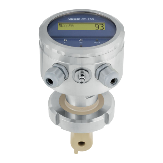
JUMO CTI-750
Inductive Conductivity/Concentration and
Temperature Transmitter with Switch Contacts
Operating manual
20275616T90Z001K000
V3.00/EN/00488788
Related Manuals for JUMO CTI-750
Summary of Contents for JUMO CTI-750
-
Page 1
JUMO CTI-750 Inductive Conductivity/Concentration and Temperature Transmitter with Switch Contacts Operating manual 20275616T90Z001K000 V3.00/EN/00488788… -
Page 2
WARNING! A sudden failure of the instrument or of a sensor connected to it could result in dangerous overdosing. Please take suitable precautionary measures for this case. NOTE! All the nececssary settings are described in this manual. However, if any difficulties should arise during start-up, please do not carry out any unauthorized manipulations. -
Page 3: Table Of Contents
Contents Typographical conventions …………5 Warning signs ………………..5 Note signs ………………..5 General ………………6 Foreword ………………….6 Structure ………………….6 Inductive conductivity measurement ……..8 Range of Applications ………………8 Function …………………..9 Identifying the device version ……….10 Nameplate ………………..10 Order details ………………..11 Device description …………..
-
Page 4
Contents 10.1 Operating elements ………………41 10.2 Operation principle ………………43 10.3 Principle …………………45 10.4 Measurement mode ……………….46 10.5 Operating level ……………….46 10.6 Administrator level ………………54 10.7 Calibration level ………………56 10.8 The desalination function …………….57 Calibration …………….61 11.1 General …………………..61 11.2 Calibration of the relative cell constant …………61 11.3 Calibration of the temperature coefficient of the measurement solution …63… -
Page 5: Typographical Conventions
1 Typographical conventions Warning signs DANGER! This symbol is used when there may be danger to personnel if the instruc- tions are ignored or not followed correctly! CAUTION! This symbol is used when there may be damage to equipment or data if the instructions are ignored or not followed correctly! Note signs NOTE!
-
Page 6: General
2 General Foreword Please read the operating manual before you commission the device. Store the operating manual at a place that is accessible for all users at all times. NOTE! All the required settings are described in this manual. Should there be any difficulties nonetheless at the time of commissioning, we request you not to carry out any impermissible manipulations.
-
Page 7
2 General 2.2.2 Transmitter with separate sensor Example Transmitter (with or without graphics LC-display) Process connection Temperature sensor Inductive conductivity measuring probe… -
Page 8: Inductive Conductivity Measurement
3 Inductive conductivity measurement Range of Applications General The inductive measurement process allows a mostly maintenance-free acqui- sition of the specific conductivity even in difficult medium conditions. In con- trast to the conductive measurement process, problems like electrode replacement and polarization do not occur. Brief description The device is used for the measurement/control of the conductivity/concentra- tions of liquid media.
-
Page 9: Function
3 Inductive conductivity measurement Function of the transmitter The device is conceived for use at the location. A robust housing protects the electronics and the electrical connections from aggressive ambient influences (system of protection IP67). In the standard version, the device has one analog signal input for the conductivity/concentration and the temperature.
-
Page 10: Identifying The Device Version
4 Identifying the device version Nameplate On the transmitter The nameplate is affixed to the case. On the separate sensor The nameplate (flag tag) is affixed to the connecting cable. Contents The nameplate contains important information. This includes: Description Description on the Example nameplate Device type…
-
Page 11: Order Details
JUMO CTI-750 head transmitter in plastic housing, without display/keypad 202756/15 JUMO CTI-750 head transmitter in plastic housing, with display/keypad 202756/16 JUMO CTI-750 head transmitter in stainless steel housing, with display/keypad (2) Process connection Screw connection G 1 ½ A Screw connection G 2 A…
-
Page 12
202756/66 JUMO CTI-750 transmitter in stainless steel housing, with display/keypad (with sensor) cable length 10 m 202756/80 JUMO CTI-750 replacement sensor with 10 m cable for transmitter in plastic b, c housing (without transmitter) 202756/85 JUMO CTI-750 replacement sensor with 10 m cable for transmitter in stainless… -
Page 13
4 Identifying the device version Cell material PEEK Cell material PVDF Supply voltage 24 V AC Hygienic design The PC setup program is required for programming the device, see accessories. A calibration kit is absolutely essential for commissioning. If not available, please include in your order (see accessories). -
Page 14
4 Identifying the device version Accessories Type Part No. Flange DN 32, material: PP 00083375 Flange DN 50, material: PP 00083376 Weld-on threaded adapter DN 50, DIN 11851 00085020 Ring nut DN 50, DIN 11851 00343368 Ring nut SMS DN 2“, Mutter 00345162 M12 plug connector, 8-pole, straight, for assembly by user 00444307… -
Page 15: Device Description
5 Device description Technical data 5.1.1 Conductivity transmitter A/D converter Resolution 15 bits Sampling time 500 ms = 2 measurements/s Power supply For SELV and PELV circuit operation only. Standard 19 — 31 V DC (24 V DC nominal) Residual ripple <5 % Reverse polarity protection Extra code 844…
-
Page 16
5 Device description 5.1.2 Measuring ranges There is a choice of four different measuring ranges. Any one of these ranges can be activated by an external switch or by a PLC. NOTE! The overall accuracy is composed of transmitter accuracy + sensor accuracy. -
Page 17: Temperature Compensation
5 Device description 5.1.3 Temperature transmitters Temperature acquisition Manually, -20.0 to 25.0 to 150 °C or °F, or automatically Measuring range -20 — 150 °C or °F Characteristic linear ≤ 0.5 % of the measuring range Accuracy ≤ 0.1 %/K Ambient temperature effect Output signal 0 — 10 V or 10 — 0 V…
-
Page 18
5 Device description 5.1.5 Inductive conductivity sensor Measuring range Accuracy (as % of measuring range span) ≤ 1 % 0 — 500 µS/cm ≤ 1 % 0 — 1000 µS/cm ≤ 0,5 % 0 — 2000 µS/cm ≤ 0,5 % 0 — 5000 µS/cm ≤… -
Page 19: Mounting
6 Mounting General 6.1.1 Installation location The compatibility of the material with the measurement medium must be checked by the customer. Ensure easy accessibility for subsequent calibration. The fastening must be secure and low-vibration. Avoid direct sunlight. It is necessary to pay attention to a good flow through and around the sensor (3). When installing in a pipe, a minimum distance of 20 mm must be maintained from the sensor to the pipe wall.
-
Page 20: Dimensions Head Transmitter
6 Mounting Dimensions head transmitter 6.2.1 Process connections Version with process connection Version with process connection 108 = screw-in thread G 1 1/2 A 107 = screw-in thread G 1 1/4 A 110 = screw-in thread G 2 A 108 = screw-in thread G 1 1/2 A and extra code 767 110 = screw-in thread G 2 A and extra code 768…
-
Page 21
6 Mounting 2 (607) Version with process connection Version with process connection 607 = MK DN 50 606 = MK DN 40 608 = MK DN 65 607 = MK DN 50 609 = MK DN 80 608 = MK DN 65 and extra code 767 609 = MK DN 80 and extra code 768… -
Page 22
6 Mounting 1 (617) 2 (616) Version with process connection Version with process connection 616 = Clamp 2″ 617 = Clamp 2 1/2″ 617 = Clamp 2 1/2″ and extra code 768 and extra code 767 and 941 (retaining clip not included in delivery) (retaining clip not included in delivery) Version with process connection ®… -
Page 23
6 Mounting < 200Nm < 200Nm Version with process connection Version with process connection 690 = SMS 2″ 690 = SMS 2″ < 200Nm) < 200Nm) and extra code 767 and 941 and extra code 768 1 = stainless steel 1.4301 2 = PEEK 3 = PVDF… -
Page 24: The Device With Separate Sensor
6 Mounting The device with separate sensor 6.3.1 Operating unit Transmitter with separate sensor, in plastic housing with basic type extension 20 or 25 and electrical connection 82 ø110 6.3.2 Wall mounting…
-
Page 25: Process Connections
6 Mounting 6.3.3 Process connections Version with process connection Version with process connection 108 = screw-in thread G 1 1/2 A 107 = screw-in thread G 1 1/4 A 110 = screw-in thread G 2 A 108 = screw-in thread G 1 1/2 A and extra code 767 110 = screw-in thread G 2 A and extra code 768…
-
Page 26
6 Mounting 2 (607) Split version with process connection Split version with process connection 607 = MK DN 50 606 = MK DN40 608 = MK DN 65 607 = MK DN50 609 = MK DN 80 608 = MK DN65 and extra code 767 609 = MK DN80 (retaining clip not included in delivery) -
Page 27
6 Mounting 1 (617) 2 (616) Split version with process connection Split version with process connection 616 = Clamp 2″ 617 = Clamp 2 1/2″ 617 = Clamp 2 1/2″ and extra code 768 and extra code 767 (retaining clip not included in delivery) (retaining clip not included in delivery) 1 = stainless steel 1.4301 2 = PEEK… -
Page 28
6 Mounting Split version with process connection Split version with process connection 690 = SMS 2″ 690 = SMS 2″ and extra code 767 and extra code 768 (retaining clip not included in (retaining clip not included in < 200Nm) <… -
Page 29
6 Mounting ø18 ø100 ø165 Optional accessory DN 32 Flange Part no. 00083375 ø18 ø125 ø165 Split version with process connection 706 Optional accessory immersion model DN 50 Flange (pipe clips not included in delivery) Part no. 00083376 3 = PVDF 6 = PBT 7 = brass nickel plated EPDM… -
Page 30: Mounting Examples
6 Mounting Mounting examples Threaded pipe adapter Process connection 607, screwed pipe fitting DN 50, DIN 11851 (MK DN 50, milk cone), PEEK Ring nut DN 50, stainless steel 1.4301 Weld-on threaded pipe adaptor DN 50, DIN 11851, stainless steel 1.4404 (matching part for process connection 607) Tee DIN 11852, short, DN 50, stainless steel 1.4301 (to be provided by the plant operator;…
-
Page 31
6 Mounting Clamp Process connection 617, Clamp 2 1/2″, PEEK Clamping ring , stainless steel 1.4301 (to be provided by the plant operator; not supplied by device manufacturer) Tee, short, 2.5″ — 2″ similar to DIN 11852, and 2″ clamp adapter, stainless steel 1.4301 (to be provided by the plant operator;… -
Page 32
6 Mounting 6.4.1 Kit for pipe mounting NOTE! The pipe-mounting kit is also suitable for horizontal pipes. for type 202756, part no. 00515128… -
Page 33: Installation
7 Installation DANGER! The electrical connections may only be set up by technically qualified personnel. • When selecting the conductor material for the installation and for the elec- trical connections of the device, compliance is required with the specifica- tions of VDE 0100 «Regulations governing the installation of heavy-current systems with rated voltages below 1000 V»…
-
Page 34: General
7 Installation General Open the operating unit Unscrew the cover (1) Remove captive fastening screw (2) and carefully take out operating unit. Connect the cables SETUP CAUTION! For connecting the individual cores, pull out the threaded plug therminals (1) in the operating unit. Lead the connecting cables through the cable glands (2).
-
Page 35: Electrical Connection
7 Installation Wiring DANGER! In the case of devices with a separate sensor, for every instrument, the transmitter and the separate sensor are matched to one another at the factory. When connecting the components, ensure that the production number of the external sensor (on the flag tag on the connecting cable) is identical to the production number of the transmitter (on the nameplate).
-
Page 36
7 Installation ATTENTION! In devices with a separate sensor and M12 plug / socket connectors, the screw terminals in the device are painted over. Removing this paint voids the warranty! SETUP Terminal assignment Symbol Supply Supply (with reverse-polarity protection) Outputs Analog signal output: conductivity/concentration (electrically isolated) -
Page 37
7 Installation Terminal assignment Symbol Binary inputs Binary input E1 Binary input E2 7.2.2 Transmitter with electrical connection 83 (M12 plug-and-socket connection) Head transmitter Connector I Power supply and actual value output for conductivity/concentration M12 flush-type connector, 5-pin Blanking plug Connector II Actual value output for temperature, and binary input and switching outputs M12 flush-type connector, 8-pin… -
Page 38
7 Installation ATTENTION! In devices with a separate sensor and M12 plug / socket connectors, the screw terminals in the device are painted over. Removing this paint voids the warranty! Supply Connector Assignment Symbol Supply (with reverse-polarity protection) Outputs Analog signal output: conductivity/concentration (electrically isolated) Analog signal output:… -
Page 39: Setup-Program
8 Setup-Program Function Configurable parameters With the optional Setup program that is available, the transmitter can be com- fortably matched to the requirements. • Setting the measurement range and the measurement range limits. • Setting the behavior of the outputs in case of overshooting of the measure- ment range.
-
Page 40: Commissioning
9 Commissioning CAUTION! The measuring transmitters are checked in the factory for flawless operabil- ity and shipped ready for operation. Head transmitter or transmitter with separate sensor Install the device, see «Mounting», page 19. Connect the device, see «Installation», page 33. DANGER! In the case of devices with a separate sensor (base type supplementation (2) 66), for every instrument, the transmitter and the separate sensor are…
-
Page 41: Operation
10 Operation 10.1 Operating elements Graphical LC-display, background lit up. , confirm inputs, select menu. , interrupt inputs without saving/interrupt calibration. EXIT One menu-level back. , increase numerical value/forward the selection. , decrease numerical value/forward the selection. LEDs «K1″/»K2» indicate the status of the switching outputs. In normal operation, the LED flows when the corresponding switching output is active.
-
Page 42
10 Operation LC-Display (11) (10) Output K1 is active Output K2 is active Binary input 1 is triggered Binary input 2 is triggered Keyboard is locked Device status (hints) • Alarm (e.g. overrange • Calib. flashing (calibration timer • Calib (customer calibration enabled) Output mode •… -
Page 43: Operation Principle
10 Operation 10.2 Operation principle 10.2.1 Operating in levels Measurement mode, see chapter 10.4 «Measurement mode», page 46 OPERATOR LEVEL, see chapter 10.5 «Operating level», page 46 INPUT CONDUCTIVITY MEASUREMENT RANGE 1…4 TEMP.COMPENSATION TEMP.COEFFICIENT 1…4 REFERENCE TEMPERATURE REL.CELL CONSTANT MOUNTING FACTOR CONCENTR.MEASUREMENT CONCENTR.RANGE OFFSET…
-
Page 44
10 Operation DEVICE DATA LANGUAGE CONTRAST LIGHTING LCD INVERSE ADMINISTR.-LEVEL, see chapter 10.6 «Administrator level», page 54 Password PARAMETER-LEVEL, see chapter 10.6.1 «Parameter level», page 55 INPUT CONDUCTIVITY. OUTPUT CONDUCTIVITY INPUT TEMPERATURE OUTPUT TEMPERATURE OUTPUT BINARY 1 OUTPUT BINARY 2 INPUT BINARY 1 INPUT BINARY 2 DESALINATION FUNCTION… -
Page 45: Principle
10 Operation 10.3 Principle Level…
-
Page 46: Measurement Mode
10 Operation 10.4 Measurement mode Depiction In the measurement mode, the conductivity compensated to the reference temperature, or the concentration, and the temperature of the measurement medium are displayed. MEASUREMENT -> Measurement mode 20.5 °C -> Temperature of the measurement medium 203 mS/cm ->…
-
Page 47
10 Operation 10.5.1 INPUT CONDUCTIVITY (Input conductivity) MEASUREMENT RANGE 1 … 4 0 to 500 µS/cm 0 to 1000 µS/cm 0 to 2000 µS/cm 0 to 5000 µS/cm 0 to 10 mS/cm 0 to 20 mS/cm 0 to 50 mS/cm 0 to 100 mS/cm 0 to 200 mS/cm 0 to 500 mS/cm… -
Page 48
10 Operation CONCENTR. MEASUREMENT NO FUNCT. NaOH HNO3 CUST. SPEC. (The input of the values is only possible with the optional Setup program) CONCENTR. RANGE In case of HNO 0 to 25 % by WEIGHT 36 to 82 % by WEIGHT In case of NaOH 0 to 15 % by WEIGHT 25 to 50 % by WEIGHT… -
Page 49
10 Operation 10.5.2 OUTPUT CONDUCTIVITY. (Output conductivity) SIGNAL TYPE 0 to 20 mA 4 to 20 mA 20 to 0 mA 20 to 4 mA 0 to 10 V 2 to 10 V 10 to 0 V 10 to 2 V SCALING START 1 … -
Page 50
10 Operation 10.5.3 INFLOW TEMPERATURE UNIT °C °F MEASUREMENT VALUE ACQUISITION Sensor manual MANUAL SPECIFICATION -20.0 to 25.0 to 150.0 °C OFFSET -15.0 to 0.0 to +15.0 °C FILTERING TIME 00:00:00 to 00:00:01 to 00:00:25 H:M:S 10.5.4 OUTFLOW TEMPERATURE SIGNAL TYPE 0 to 20 mA 4 to 20 mA 20 to 0 mA… -
Page 51
10 Operation MANUAL OPERATION MANUAL VALUE 0,0 to 4,0 to 22,0 mA (depending on the signal type) 0 to 10.7 V 10.5.5 OUTPUT BINARY 1 and OUTPUT BINARY 2 FUNCTION NO FUNCTION COND. MIN. COND. MAX. COND. AF1 COND. AF2 TEMP. -
Page 52
10 Operation Wiper contact Wiper contact Triggering condition longer than Triggering condition shorter than pulse duration pulse duration LIMIT VALUE -20.0 to 999.0 (depending on the function, see above) HYSTERESIS 0.0 to 1.0 to 999.0 (depending on the function, see above) DISTANCE 0.0 to 999.0 (depending on the function, see above) MANUAL OPERATION… -
Page 53: Desalination Function
10 Operation 10.5.6 INPUT BINARY 1 and INPUT BINARY 2 FUNCTION NO FUNCTION KEYBOARD LOCK/HOLD MEASUREMENT RANGE./TEMP C. DESALINATION FUNCTION. Setting parameters binary input 1 binary input 2 Measurement range- / MB1/Tk1 open open Temperature- MB2/Tk2 closed open coefficient switching MB3/Tk3 open closed…
-
Page 54: Administrator Level
10 Operation 10.5.8 DEVICE DATA LANGUAGE GERMAN ENGLISH FRENCH SPANISH POLISH SWEDISH ITALIAN PORTUGUESE DUTCH RUSSIAN NOTE! By inputting the password 7485 in the Administrator level, the operating lan- guage is reset to English. CONTRAST 0 to 6 to 11 LIGHTING FOR OPERATION (about 50 s after the last keystroke,…
-
Page 55
10 Operation Levels of the Administrator level 10.6.1 Parameter level In this level, the Administrator can edit any parameter of the operator level. The structure of the parameter level in the Administrator level is identical to the operator level, see «Operating level», page 46 and onwards. 10.6.2 Release level In this level, the Administrator can determine which parameters the operator is permitted to modify in the operator level. -
Page 56: Calibration Level
10 Operation 10.7 Calibration level In this level, the calibrations released by the Administrator (Administrator level) can be carried out. Press the key for longer than 3 seconds. With the keys , select «CALIBRATION-LEVEL». 10.7.1 REL. CELL CONSTANT. (relative cell constant) If this function has been released by the Administrator, the operator can cali- brate the relative cell constant of the device here;…
-
Page 57: The Desalination Function
10 Operation 10.8 The desalination function Brief description In the case of cooling water, using the conductivity, the total salt content is assessed. Upon reaching a limiting conductivity (at maximum permissible salt concentration/densification), dilution of the cooling water is necessary. For this purpose, a desalination valve is opened, densified water flows out and is sup- plemented with fresh water.
-
Page 58
10 Operation 10.8.1 Setting the desalination function All the parameters are plant-dependent and must be matched to the prevalent conditions. Press the key for longer than 3 seconds. With the keys , select the «OPERATOR LEVEL»; with key , con- firm the selection. -
Page 59
10 Operation Use the key to switch to the operator level. EXIT With the key select «DESALINATION FUNCTION». With key , confirm the selection. Set the desalination reduction with the keys in the range from 1 to 10 to 50% below the actual limit value. with key , confirm the setting. -
Page 60
10 Operation Set the locking time with the keys in the range from 0:00:00 to 00:01:00 to 18:00:00 H:M:S. with key , confirm the setting. NOTE! If there is a failure of the supply voltage during the running of the desalina- tion function, the function is canceled. -
Page 61: Calibration
11 Calibration 11.1 General For increasing the accuracy, the device has various calibration options. NOTE! At regular intervals (depending on the measurement medium), the conduc- tivity sensor must be cleaned and calibrated. The LED «K1» flashes during the calibration. 11.2 Calibration of the relative cell constant In case of increased demands on the accuracy, the cell constant must first be calibrated.
-
Page 62
11 Calibration With the keys , select «REL. CELL CONSTANT.». with key confirm the selection. When the measured value is stable, press the key. With the keys , correct the displayed uncompensated conductiv- ity value to the conductivity value of the reference solution. Press the key. -
Page 63: Calibration Of The Temperature Coefficient Of The Measurement Solution
11 Calibration 11.3 Calibration of the temperature coefficient of the mea- surement solution 11.3.1 Linear temperature coefficient (ALPHA) The conductivity of any measurement solution changes according it its spe- cific temperature coefficient. We therefore recommend carrying out the calibration of the temperature coef- ficient Precondition •…
-
Page 64
11 Calibration With the keys , input the operating temperature and confirm with key . NOTE! The operating temperature must be at least 5 °C above or below the refer- ence temperature (25.0 °C). The LC-Display now shows the selected operating temperature (flashing) the reference temperature (flashing) the current sensor temperature (static) Heat the measurement medium till both the reference temperature as well… -
Page 65
11 Calibration The LC-display now shows the determined temperature coefficient in %/K. Accept the temperature coefficient determined -> press the key for longer than 3 seconds, or discard the value -> press the key EXIT The transmitter is in the «Calibration menu». Press key EXIT The transmitter is in «Measurement mode»… -
Page 66
11 Calibration 11.3.2 Non-linear temperature coefficient (ALPHA) General Since the temperature coefficient of some media is not constant over a larger temperature range, the device has the facility to divide a temperature range to T ) into 5 sub-ranges. In each of these ranges, compensation can start be carried out with different TC values. -
Page 67
11 Calibration TC-curve Temperature compensation with the TC-curve With the help of the current medium temperature, the corresponding tempera- ture coefficient is determined from the TC curve, see «TC-curve», page 67. Intermediate values, e.g. (α in the case of T ) between two determined values (α… -
Page 68
11 Calibration Sequence of the automatic calibration The TC curve is plotted automatically in a temperature range determined by the user. Here, the temperature range from the starting to the final temperature is divided into 5 equal sections. The temperature range must be greater than 20 Kelvin and overlap the refer- ence temperature. -
Page 69
11 Calibration With the keys , input the starting temperature and confirm with key . NOTE! The starting temperature must be below the reference temperature (25.0 °C). With the keys , input the final temperature and confirm with the key . NOTE! The final temperature must be at least 20 °C above the starting temperature. -
Page 70
11 Calibration Heat the measurement medium till the flashing temperature is exceeded or undershot. The next temperature to be reached is displayed flashing. CAUTION! During the calibration, the temperature changing speed of the measurement solution of 10 K/min in the case of the device with a free-standing temperature sensor 1 K/min in the case of the device with an integrated temperature sensor must not be exceeded. -
Page 71: Maintenance
12 Maintenance 12.1 Conductivity-clean sensor CAUTION! Do not use any solvents. Stubborn sediments or deposits can be dissolved with dilute hydrochloric acid and removed. Comply with the safety specifications. Deposits Deposits on the sensor part can be removed with a soft brush (e.g. bottle brush).
-
Page 72: Rectifying Errors And Faults
13 Rectifying errors and faults Error possibilities Problem Possible cause Measure No display of measured value Voltage supply absent Check voltage supply, check terminals signal output Measured value display Sensor not submerged in me- Fill up tank 000 or dium; signal output 0 % Tank level too low (e.g.
-
Page 73: Device Checking
13 Rectifying errors and faults 13.1 Device checking General The device is calibrated at the factory and is maintenance-free. If measure- ment value variations from unknown causes should occur nonetheless, the transmitter can be checked as follows. 13.1.1 Checking with resistance loop Cell constant CAUTION! The cell constant of the device depends on the design type!
-
Page 74
13 Rectifying errors and faults Connect the resistance R to the wire Calculation of the resistance Formula for calculation of the resistance of the resistance loop: · K Resistance of the resistance loop Number of turns in the loop Cell constant desired display in S/cm Remark: 1 mS/cm = 1·10… -
Page 75
13 Rectifying errors and faults Pre-calculated values The display value 0 is reached when the following conditions are met: • The sensor is dry • The sensor is free of any conducting coats • No resistance loop is mounted. Display at No. -
Page 76
13 Rectifying errors and faults 13.1.2 Testing with reference fluid Put in test solution Carry out test Prepare the conductivity test solution in a sufficiently large container Connect the device electrically, see chapter 7 «Installation», page 33. Select the measurement range according to the conductivity test solution, see chapter 10.5.1 «INPUT CONDUCTIVITY (Input conductivity)», page 47 — >… -
Page 77
13 Rectifying errors and faults 13.1.3 Testing with reference measuring instrument Put in test solution Carry out test Prepare the conductivity test solution in a sufficiently large container Connect the device electrically, see chapter 7 «Installation», page 33. Select the measurement range according to the conductivity test solution, see chapter 10.5.1 «INPUT CONDUCTIVITY (Input conductivity)», page 47 — >… -
Page 78: Annex
14 Annex 14.1 Before configuring If many parameters of the device are to be re-configured, it is advisable to make a note of all the parameters to be changed in the following table, and to process the parameters in the given sequence. NOTE! The following list shows the maximum number of modifiable parameters.
-
Page 79
14 Annex Parameter Selection/Range of values New setting see page Factory setting Signal type 0 to 20 mA 4 to 20 mA 20 to 0 mA 20 to 4 mA 0 to 10 V 2 to 10 V 10 to 0 V 10 to 2 V Scaling, beginning 0 to 90 % = 4 mA (e.g.) -
Page 80
14 Annex Parameter Selection/Range of values New setting see page Factory setting In case of an alarm high safety value At the time of calibration accompanying frozen safety value Safety value 0.0 to 4.0 to 22.0 mA Manual operation Manual value 0.0 to 4.0 to 22.0 mA Output binary 1 or binary 2 Function… -
Page 81
14 Annex Parameter Selection/Range of values New setting see page Factory setting Dosing time 00:00:00 to 00:01:00 to 18:00:00 H:M:S Locking time 00:00:00 to 00:01:00 to 18:00:00 H:M:S Device data Language German English French Spanish Polish Swedish Italian Portuguese Dutch Russian Contrast 0 to 6 to 11… -
Page 82
14 Annex… -
Page 83: China Rohs
15 China RoHS…
-
Page 84: Index
16 Index – – Alarm window In case of alarm – – At the time of calibration In case of alarm/calibration In case of hold Inflow temperature Input binary Biocide Input conductivity Input, conductivity Installation location Calculation of a temperature coefficient Inverse LCD Calibration interval Cell constant…
-
Page 85
16 Index Pulse duration Re-configuring Reduction Reference fluid Reference measuring instrument Reference temperature Relative cell constant Resistance loop – – Safety value Scaling – – start Setting parameters Setup interface – Signal type Solvent Sunlight Switch-off delay Switch-on delay TC-curve Temperature coefficient Temperature compensation with the TC-curve… -
Page 88
JUMO GmbH & Co. KG JUMO Instrument Co. Ltd. JUMO Process Control, Inc. Street address: JUMO House 6733 Myers Road Moritz-Juchheim-Straße 1 Temple Bank, Riverway East Syracuse, NY 13057, USA 36039 Fulda, Germany Harlow, Essex, CM20 2DY, UK Delivery address:…
- Manuals
- Brands
- Jumo Manuals
- Transmitter
- CTI-750
Manuals and User Guides for Jumo CTI-750. We have 4 Jumo CTI-750 manuals available for free PDF download: Operating Instructions Manual, Operating Manual
JUMO CTI-750 Operating Manual (76 pages)
Inductive conductivity transmitter in stainless steel housing
Brand: JUMO
|
Category: Transmitter
|
Size: 1.4 MB
Table of Contents
-
Table of Contents
3
-
1 Typographical Conventions
8
-
Warning Signs
8
-
Attention-Drawing Signs
8
-
-
2 General
9
-
Foreword
9
-
Structure of the JUMO CTI-750
10
-
-
3 Inductive Conductivity Measurement
11
-
Field of Application
11
-
Function
12
-
-
4 Identifying the Device
13
-
Type Nameplate
13
-
Type Declaration
14
-
JUMO CTI-750 as «Head Transmitter
14
-
JUMO CTI-750 as «Transmitter with Separate Sensor
15
-
-
5 Device Description
17
-
Technical Data, Transmitter
17
-
Output Signal
18
-
Output Signal, Temperature
19
-
Pressure
20
-
-
-
6 Assembly
21
-
General
21
-
Dimensions / Process Connections, Head Transmitter
22
-
JUMO CTI-750 with Separate Sensor
24
-
Assembly Examples
28
-
Weld-On Threaded Connector
28
-
-
7 Installation
30
-
General
31
-
Removing the Pigmenting
32
-
Outputs
33
-
-
-
8 Setup Program
34
-
Function
34
-
-
9 Commissioning
35
-
Head Transmitter or Transmitter with Separate Sensor
35
-
Replacement Sensor
35
-
-
10 Operation
36
-
Operating Elements
36
-
Principle of Operation
38
-
Operation Principle
38
-
Principle
40
-
Measurement Mode
41
-
Operator Level
41
-
Input Conductivity
42
-
Mounting Factor
43
-
Output Conductivity
44
-
Unit
45
-
Output Binary
46
-
Distance
47
-
Desalination Function
48
-
-
Administrator Level
49
-
Levels of the Administrator Level
50
-
Calibration Level
51
-
The Desalination Function
52
-
Desalination Reduction
53
-
-
11 Calibrating
56
-
General
56
-
Calibration of the Relative Cell Constant
56
-
Calibration of the Temperature Coefficient of the Measurement Solution
57
-
Determining the TC-Curve
60
-
-
12 Maintenance
65
-
Cleaning the Conductivity Sensor
65
-
-
13 Rectifying Errors and Faults
66
-
Device Inspection
66
-
Pre-Calculated Values
69
-
-
14 Annex
72
-
Before Configuring
72
-
Unit
73
-
Distance
74
-
Lighting
75
-
-
Advertisement
Jumo CTI-750 Operating Manual (88 pages)
Inductive Conductivity/Concentration and Temperature Transmitter with Switch Contacts
Brand: Jumo
|
Category: Transmitter
|
Size: 2.2 MB
Table of Contents
-
Table of Contents
3
-
1 Typographical Conventions
5
-
Warning Signs
5
-
Note Signs
5
-
-
2 General
6
-
Foreword
6
-
Structure
6
-
-
3 Inductive Conductivity Measurement
8
-
Range of Applications
8
-
Function
9
-
-
4 Identifying the Device Version
10
-
Nameplate
10
-
Order Details
11
-
-
5 Device Description
15
-
Technical Data
15
-
Temperature Compensation
17
-
-
6 Mounting
19
-
General
19
-
Dimensions Head Transmitter
20
-
The Device with Separate Sensor
24
-
Process Connections
25
-
Mounting Examples
30
-
-
7 Installation
33
-
General
34
-
Electrical Connection
35
-
-
8 Setup-Program
39
-
Function
39
-
-
9 Commissioning
40
-
Head Transmitter or Transmitter with Separate Sensor
40
-
Replacement Sensor
40
-
-
10 Operation
41
-
Operating Elements
41
-
Operation Principle
43
-
Principle
45
-
Measurement Mode
46
-
Operating Level
46
-
Desalination Function
53
-
Administrator Level
54
-
Calibration Level
56
-
The Desalination Function
57
-
-
11 Calibration
61
-
General
61
-
Calibration of the Relative Cell Constant
61
-
Calibration of the Temperature Coefficient of the Measurement Solution
63
-
-
12 Maintenance
71
-
Conductivity-Clean Sensor
71
-
-
13 Rectifying Errors and Faults
72
-
Device Checking
73
-
-
14 Annex
78
-
Before Configuring
78
-
-
15 China Rohs
83
-
16 Index
84
JUMO CTI-750 Operating Instructions Manual (88 pages)
Inductive Conductivity/Concentration and Temperature Transmitter with switch contacts
Brand: JUMO
|
Category: Transmitter
|
Size: 1.18 MB
Table of Contents
-
Table of Contents
3
-
1 Typographical Conventions
5
-
Warning Signs
5
-
Note Signs
5
-
-
2 General
6
-
Preface
6
-
Device Configuration
6
-
-
3 Inductive Conductivity Measurement
8
-
Area of Application
8
-
Function
9
-
-
4 Instrument Identification
10
-
Nameplate
10
-
Type Designation
11
-
The Device as «Head Transmitter
11
-
The Device as «Transmitter with Separate Sensor
12
-
-
5 Instrument Description
15
-
Technical Data
15
-
Temperature Compensation
17
-
-
6 Installation
19
-
General
19
-
Head Transmitter Dimensions
20
-
Device with Separate Sensor
24
-
Process Connections
25
-
Mounting Examples
31
-
-
7 Installation
35
-
General
36
-
Electrical Connection
37
-
-
8 Setup Program
42
-
Function
42
-
-
9 Commissioning
43
-
Head-Mounted Transmitter or Transmitter with Separate Sensor
43
-
Replacement Sensor
43
-
-
10 Operation
44
-
Controls
44
-
Principle of Operation
46
-
Principle of Operation
48
-
Measurement Mode
49
-
Operator Level
49
-
Administrator Level
57
-
Calibration Level
59
-
Dilution Function
60
-
-
11 Calibration
64
-
General
64
-
Calibrating the Relative Cell Constant
64
-
Calibrating the Temp. Coefficient of the Sample Solution
66
-
-
12 Maintenance
74
-
Cleaning the Conductivity Sensor
74
-
-
13 Eliminating Faults and Malfunctions
75
-
Checking the Instrument
76
-
-
14 Appendix
81
-
Before Configuration
81
-
Advertisement
Jumo CTI-750 Operating Instructions Manual (68 pages)
Inductive Conductivity Transmitter
Brand: Jumo
|
Category: Transmitter
|
Size: 1.86 MB
Table of Contents
-
Table of Contents
3
-
1 Typographical Conventions
5
-
Warning Signs
5
-
Note Signs
5
-
-
2 General
6
-
Preface
6
-
Design of the JUMO CTI-750
7
-
-
3 Inductive Conductivity Measurement
8
-
Area of Application
8
-
Function
9
-
-
4 Instrument Identification
10
-
Nameplate
10
-
Type Designation
11
-
JUMO CTI-750 as «Head-Mounted Transmitter
11
-
JUMO CTI-750 as «Transmitter with Separate Sensor
12
-
-
5 Instrument Description
13
-
Technical Data for Transmitter
13
-
Temperature Compensation
15
-
-
6 Mounting
17
-
General
17
-
Dimensions / Process Connections for Head Transmitter
18
-
JUMO CTI-750 with Separate Sensor (Split Version)
19
-
Mounting Examples
21
-
-
7 Installation
23
-
General
24
-
-
8 Setup Program
27
-
Function
27
-
-
9 Commissioning
28
-
Head-Mounted Transmitter or Transmitter with Separate Sensor
28
-
Replacement Sensor
28
-
-
10 Operation
29
-
Controls
29
-
Principle of Operation
31
-
Measurement Mode
32
-
Operator Level
32
-
Administrator Level
40
-
Calibration Level
42
-
Dilution Function
43
-
-
11 Calibration
47
-
General
47
-
Calibrating the Relative Cell Constant
47
-
Calibrating the Temp. Coefficient of the Sample Solution
48
-
-
12 Maintenance
56
-
Cleaning the Conductivity Sensor
56
-
-
13 Eliminating Faults and Malfunctions
57
-
Checking the Instrument
57
-
-
14 Appendix
63
-
Before Configuration
63
-
Advertisement
Related Products
-
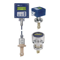
JUMO CTI-500
-
JUMO cTRON 04
-
JUMO cTRON 16
-
JUMO cTRON 08
-
JUMO dTRANS CR 02
-
JUMO tecLine ClO2
-
JUMO digiLine CR HT10
-
JUMO digiLine CR HT30
-
JUMO digiLine CR ST10
-
JUMO tecLine CR-4P
Jumo Categories
Transmitter
Measuring Instruments
Controller
Thermostat
Voice Recorder
More Jumo Manuals
JUMO CTI-750
Inductive Conductivity Transmitter
Type 202756
B 20.2756.0
Operating Instructions
11.07/00452846
WARNING:
A sudden failure of the instrument or of a sensor connected to it could result in dangerous overdosing. Please take suitable precautionary measures for this case.
Please assist us to improve these operating instructions, where necessary.
Your comments will be appreciated.
Phone (06 61) 60 03-7 14
Fax (06 61) 60 03-6 05
All the nececssary settings are described in this manual. However, if any difficulties should arise during start-up, please do not carry out any unauthorized manipulations. You could endanger your righs under the instrument warranty!
Please contact the nearest subsidiary or the head office in such a case.
In case of technical questions
Service hotline:
Phone: (06 61) 60 03-3 00 oder (06 61) 60 03-6 53
Fax: (06 61) 60 03-88 13 00 oder (06 61) 60 03-88 16 53 e-mail: [email protected]
Resetting the LC display
If the brightness/contrast setting is such that the text in the display is not readable, the basic setting can be restored as follows:
Q Switch off the supply voltage.
Q Switch on the supply voltage and immediately keep the keys and held down.
Resetting the operating language to «English»
If the operating language has been set and you cannot understand the text of the display, the language can be set to «English» with the Administrator password 7485. Thereafter, the desired language can be set in ADMINISTRATOR LEVEL / DEVICE DATA / ….
Contents
1.1
1.2
Warning signs ………………………………………………………………………………….5
Note signs ……………………………………………………………………………………….5
2.1
2.2
3
3.1
3.2
Preface ……………………………………………………………………………………………6
Design of the JUMO CTI-750 ……………………………………………………………..7
Inductive conductivity measurement ……………………………….. 8
Area of application ……………………………………………………………………………8
Function ………………………………………………………………………………………….9
4.1
4.2
4.3
4.4
Nameplate ……………………………………………………………………………………..10
Type designation …………………………………………………………………………….11
JUMO CTI-750 as “Head-mounted transmitter” …………………………………11
JUMO CTI-750 as “Transmitter with separate sensor” ………………………..13
5.1
5.2
5.3
5.4
General ………………………………………………………………………………………….15
Dimensions / Process connections for head transmitter ………………………16
JUMO CTI-750 with separate sensor (split version) …………………………….18
Mounting examples …………………………………………………………………………22
6.1
Technical data for transmitter ……………………………………………………….24
7.1
General …………………………………………………………………………………………29
8.1
Function ………………………………………………………………………………………..32
9.1
9.2
Head-mounted transmitter or transmitter with separate sensor …………….33
Replacement sensor ……………………………………………………………………….33
Contents
10.1
Controls …………………………………………………………………………………………34
10.2
Principle of operation ………………………………………………………………………36
10.3
Principle of operation ………………………………………………………………………38
10.4
Measurement mode ………………………………………………………………………..39
10.5
Operator level …………………………………………………………………………………39
10.6
Administrator level ………………………………………………………………………….47
10.7
Calibration level ………………………………………………………………………………49
10.8
Dilution function ……………………………………………………………………………..50
11.1
General ………………………………………………………………………………………….54
11.2
Calibrating the relative cell constant ………………………………………………….54
11.3
Calibrating the temp. coefficient of the sample solution ………………………55
12.1
Cleaning the conductivity sensor ………………………………………………………63
13 Eliminating faults and malfunctions ……………………………….. 64
13.1
Checking the instrument ………………………………………………………………….64
14.1
Before configuration ………………………………………………………………………..70
1 Typographical conventions
1.1
Warning signs
Danger
This symbol is used when there may be danger to personnel if the instructions are ignored or not followed correctly!
Caution
This symbol is used when there may be damage to equipment or data if the instructions are ignored or not followed correctly!
1.2
Note signs
Note
This symbol is used when your special attention is drawn to a remark.
abc
1
✱
Footnote
Footnotes are remarks that refer to specific points in the text. Footnotes consist of two parts:
A marker in the text, and the footnote text.
The markers in the text are arranged as continuous superscript numbers.
Action instruction
This symbol indicates that an action to be performed is described.
The individual steps are marked by this asterisk.
Example:
✱ Remove crosspoint screws.
5
6
2 General
2.1
Preface
Please read these operating instructions before commissioning the instrument. Keep the manual in a place that is accessible to all users at all times.
Please assist us to improve these operating instructions, where necessary.
Your comments will be appreciated.
Phone +49 661 6003-0
Fax +49 661 6003-607 e-mail [email protected]
All necessary settings are described in this manual. However, if any difficulties should still arise during start-up, please do not carry out any unauthorized manipulations. You could endanger your rights under the instrument warranty!
Please contact the nearest subsidiary or the head office in such a case.
2 General
2.2
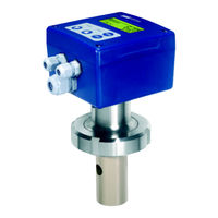
Design of the JUMO CTI-750
Examples
Version:
Transmitter combined with conductivity sensor,
Type 202756/xx…
(1)
(1)
(5)
(2)
(3)
(4)
Version:
Transmitter with separate sensor,
Type 202756/xx…
(1) Transmitter
(2) Process connection
(3) Temperature probe
(2)
(4)
(3)
(4) Inductive conductivity sensor
(5) With or without graphics LC display
7
8
3 Inductive conductivity measurement
3.1
Area of application
General
Brief description
The inductive measurement method permits largely maintenance-free acquisition of the specific conductivity, even in difficult media conditions.
Unlike the conductive measurement method, problems such as electrode decomposition and polarization do not occur.
The instrument is used for the measurement/control of conductivity or concentration in liquid media. It is particularly recommended for use in media where severe deposits of dirt, oil, grease or gypsum/lime precipitates are to be expected. The integrated temperature measurement enables fast and accurate temperature compensation, which is of particular importance when measuring conductivity. Additional functions, such as the combined changeover of measurement range and temperature coefficient, enable optimum application in CIP processes.
Two built-in switching outputs can be freely programmed to monitor limits for conductivity/concentration and/or temperature. It is also possible to assign alarm and control functions (dilution).
The instrument is operated either from the membrane keypad and plain-text graphics display (operator language can be changed over) or through the userfriendly PC setup program. Simply rotating the housing cover makes it possible to read the display, regardless of whether the installation is in horizontally or vertically arranged pipes. By using the setup program, the instrument configuration data for plant documentation can be saved and printed out. To prevent any tampering, the instrument can also be supplied without keypad or display. In this case, the setup program is needed for programming.
The JUMO CTI-750 is available either as a combined unit (transmitter and measuring cell together in one unit) or as a split version (transmitter and cell connected by cable). The split version is particularly suitable for plant subjected to strong vibration and/or significant heat radiation at the point of measurement, or for installation on sites that are difficult to access.
Typical areas of application
— CIP cleaning (CIP = Clean In Place/Process)
— concentration monitoring or dosing of chemicals
— food/beverage and pharmaceutical industries
— product monitoring (phase separation of product / product mix / water) in the beverage industry, breweries, dairies
— control (e.g. phase separation of detergent / rinsing water in cleaning processes, e.g. bottle cleaning plant, or for container cleaning)
3 Inductive conductivity measurement
3.2
Function
of the transmitter of the measuring cell
The JUMO CTI-750 transmitter has been designed for use on site. A rugged housing protects the electronics and the electrical connections from corrosive environmental conditions (enclosure IP67). As standard, the device has one analog signal output each for conductivity/concentration and temperature respectively. Further processing of the standard signals can take place in a suitable display/control device, or, for example, directly in a PLC.
The output signals are electrically isolated from one another and from the medium.
The conductivity is measured using an inductive probe. A sinusoidal a.c.
voltage feeds the transmitting coil. Depending on the conductivity of the liquid to be measured, a current is induced in the receiver coil. This current is proportional to the conductivity of the medium. The cell constant of the inductive probe depends on its geometry. The cell constant can also be affected by components in the immediate vicinity.
(1)
(4)
(2)
(5)
(1) Plastic body
(2) T-shaped flow channel
(3) Liquid loop
(3)
(4) Sample medium
(5) Pt100 temperature sensor
9
4.1
Nameplate
on the transmitter
JUMO GmbH & Co. KG
Fulda, Germany www.jumo.net
JUMO CTI-750
Typ: 202756/15-607-0000-82/000
VARTN: 20/00445843
F-Nr.: 00909467 01 0 0517 0001
on the connecting cable
(only with separate sensor)
F-Nr.: 00909467 01 0 0517 0001
For devices with a separate sensor (type code extensions (2) /60 or /65), the transmitter and detached sensor are matched to one another at the factory!
When connecting the components, please note that the serial number of the external sensor (marked on the label attached to the connecting cable) must match the serial number marked on the nameplate of the transmitter!
The date of manufacture is coded in the “F-Nr.” (serial number):
0517 means manufactured in year 2005 / calendar week 17
10
4 Instrument identification
4.2
Type designation
4.3
JUMO CTI-750 as “Head-mounted transmitter”
o o o o o o o o o o o o o o o o o o o o o o o o o o o o o o o o o o o o o o o o o o x x x o o o o o o o o o o o o
202756
10
15
16
107
108
110
606
607
608
609
617
686
690
000
82
83
84
000
580
767
768
844
(1) Basic type
JUMO CTI-750
Inductive transmitter/switching device for conductivity/concentration and temperature
(2) Basic type extensions
head-mounted transmitter im in plastic housing, without display/keypad
1 head-mounted transmitter im in plastic housing, with display/keypad head-mounted transmitter in stainless steel housing, with display/keypad
(3) Process connection
stud thread G1 1/4A stud thread G1 1/2A stud thread G 2A screwed pipe connection DN40, DIN 11 851
(MK DN40, milk cone) screwed pipe connection DN50, DIN 11 851
(MK DN50, milk cone) screwed pipe connection DN65, DIN 11 851
(MK DN65, milk cone) screwed pipe connection DN80, DIN 11 851
(MK DN80, milk cone) clamp 2 1/2″
2
VARIVENT
®
DN40/50
3
SMS 2″
(4) Immersion length
see “Dimensions / Process connections
(head-mounted transmitter)”
(5) Electrical connection
cable glands
M12 plug/socket connectors
(instead of cable glands)
4 two M16 cable glands and one blanking plug
(6) Extra codes
5
no extra code
1 set M12 plug/socket connectors cell material PEEK cell material PVDF supply voltage 24 V AC x = standard o = option
11
4 Instrument identification
Order code
Order example
(1) (2) (3) (4) (5) (6)
/ /
202756 / 10 — 607 — 000 82 / 767 ,
(6)
, …
2
3
1
4
5
The PC setup program is required for programming the instrument, see accessories.
Assembly material (holding clamps) not part of supplied kit.
Only in conjunction with extra code 767 (measuring cell material PEEK).
If required, order extra code 580.
List extra codes in sequence, separated by commas.
12
4 Instrument identification
4.4
JUMO CTI-750 as “Transmitter with separate sensor”
202756
20
25
26
60
65
66
80
85
(1) Basic type
JUMO CTI-750
Inductive transmitter/switching device for conductivity/concentration and temperature
(2) Basic type extensions
transmitter in plastic housing, without display/keypad (without sensor)
1 transmitter in plastic housing, with display/keypad
(without sensor)
2 transmitter in stainless steel housing, with display/keypad
(without sensor)
2 transmitter in plastic housing, without display/keypad including sensor (cable length: 10 m)
1 transmitter in plastic housing, with display/keypad including sensor (cable length: 10 m) transmitter in stainless steel housing, with display/keypad including sensor (cable length: 10 m) replacement sensor with 10 meter cable, for transmitter in plastic housing, without transmitter
2, 3 replacement sensor with 10 meter cable, for transmitter in stainless steel housing, without transmitter
2, 3 x x x x o o o o o o o o o o o o o o o o o o o o o o o o o o o o o o o o o o o o o o o o
000
107
108
110
606
607
608
609
617
686
690
0000
0500
1000
1500
2000 xxxx
(3) Process connection
not available stud thread G1 1/4A stud thread G1 1/2A stud thread G2A
DN40 screwed pipe fitting, DIN 11 851
DN50 screwed pipe fitting, DIN 11 851
(MK DN40, milk cone)
(MK DN50, milk cone)
DN65 screwed pipe fitting, DIN 11 851
DN80 screwed pipe fitting, DIN 11 851
(MK DN65, milk cone)
(MK DN80, milk cone) clamp 2 1/2″
3
VARIVENT
®
DN40/50
4
SMS 2″
(4) Immersion length (see “Dimensions separate sensor”)
5 not present
0 500 mm
1000 mm
1500 mm
2000 mm special length (in grid of 250 mm; e.g. 0250; 0750; 1250; 1750) o o o o o o o o o o o o x 21
82
83
84
(5) Electrical connection
fixed cable with M12 socket connector on separate sensor cable glands on the operating unit
M12 plug/socket connectors on operating unit
3
Two screwed cable glands M16 and one dummy plug
Continued, see next page
13
4 Instrument identification
x x x x x o o o o o o x x x o o o o o o o
000
580
767
768
844
(6) Extra codes
7
no extra code
1 set M12 plug/socket connectors cell material PEEK cell material PVDF supply voltage 24 V AC x = standard o = option
Order code
Order example
(1) (2) (3) (4) (5) (6)
/ /
202756 / 65 — 607 — 0000 82 / 767
(6)
, …
4
5
6
7
1
2
3
The PC setup program is required for programming the instrument, see accessories.
An equalization set is indispensable for start-up. If not available, please order (see accessories).
Fixing items (union/ring nuts, mounting brackets, holding clamps) are not included in delivery.
If required, please include in order, see accessories.
Only in conjunction with extra code 767 (measuring cell material PEEK).
Only in conjunction with extra code 768 (measuring cell material PVDF).
If required, order M12 connector/ sockets, extra code 580.
List extra codes in sequence, separated by commas.
14
5 Mounting
5.1
General
Installation site
Make sure that the site is readily accessible, for calibration at a later time.
The fixing must be secure and free from vibration.
Avoid direct sunlight!
Take care that there is adequate flow through and around the sensor (1)!
If the device is to be mounted in a pipeline, there must be at least 20 mm clearance between the sensor and the wall of the pipe.
If it is not possible to achieve this minimum clearance, then a limited compensation can be made through the “Mounting factor” parameter.
For submerged operation in basins, a location must be chosen that is representative of the typical conductivity or concentration.
Operating position
The JUMO CTI-750 can be mounted in any position.
(1)
Screwing in and unscrewing the detached sensor
The cable must not be twisted!
Avoid putting tension on the cable. In particular, avoid tugging it.
Sensor details
St. steel sleeve: Material 1.4571
Seal: FPM
15
5 Mounting
5.2
Dimensions / Process connections for head transmitter
Installation variations
Version with process connection
107 = stud thread G1 1/4A
108 = stud thread G1 1/2A
110 = stud thread G2A
Version with process connection -607
MK DN50
16
Version with process connection -617 clamp 2
1
/
2
«
(retaining clip not included in delivery)
Version with process connection -686
VARIVENT
®
DN50
(retaining clip not included in delivery)
Version with process connection -690
SMS 2″
5 Mounting
17
5 Mounting
5.3
JUMO CTI-750 with separate sensor (split version)
Transmitter head
Drilling jig for wall-mounting
18
5 Mounting
Sensor component
M12 socket
(PBT / PA)
Cabel gland
M16 (PA)
Version with process connection
107 = stud thread G1 1/4A
108 = stud thread G1 1/2A
110 = stud thread G2A
Split version with process connection -607
MK DN50
(union nut not included in delivery)
M12 socket
(PBT / PA)
Cable gland
M16 (PA)
Split version with process connection -617 clamp 2
1
/
2
«
(retaining clip not included in delivery)
Split version with process connection -686
VARIVENT
®
DN50
(retaining clip not included in delivery)
Process connection 686
(1.4301)
19
5 Mounting
Split version with process connection -690
SMS 2″
(union nut not included in delivery)
20
5 Mounting
5.3.1
Separate sensor as submersible version
M12 socket
(PBT/PA)
Cable gland
System of protection
IP68 up to 0,2 bar) according EN 60529
(PA) fixing screw flange movab
ø18
ø100
ø165
Optional accessories:
Flange DN 32, sales no. 20/00083375
Submerged pipe (PVDF)
ø40 fixing screw flange movable
ø18
ø125
ø165
Optional accessories:
Flange DN 50, sales no. 20/00083376
Shouldered version with process connection 706
Submersible version
(pipe clamps not part of delivery)
21
5 Mounting
5.4
Mounting examples
Weld-on threaded pipe adaptor
DN50, DIN 11 851
(matching part for process connection
-607)
Sales No. 20/00085020
22
5 Mounting
Tee, VARIVENT, DN50
(e.g. 1.4301)
(to be provided by the plant operator; not supplied by JUMO)
5.4.1
Pipe-mounting kit
30…50 mm
(2)
(1)
(1)
The screws (1) M5 x 30 are used with pipe diameters from 30 to 40 mm.
The screws (2) M5 x 40 are used with pipe diameters from 40 to 50 mm.
The pipe-mounting kit is also suitable for horizontal pipes.
23
6 Instrument description
6.1
Technical data for transmitter
6.1.1
General
Permissible ambient temperature
(transmitter)
Permissible storage temperature
(transmitter)
Enclosure protection
(transmitter)
Housing
Weight
A/D converter
Supply
resolution: 15-bit sampling time: 500 msec = 2 measurements/sec for operation on SELV or PELV circuits standard:
19 — 31 V DC (24 V DC nominal), with reverse-polarity protection ripple: < 5% power consumption with display:
≤ 3 W power consumption without display:
≤ 2.6 W with extra code 844:
24 V AC ±10%
Rating of the solid-state relays
I
U < 50 V AC/DC
≤ 200 mA
Electrical connection
plug-in screw terminals 2.5 mm
2
or M12 plug/socket connectors
Display (option)
graphics LCD with background lighting; adjustable contrast dimensions: 62 x 23 mm
-5 to +50°C max. 93% relative humidity, no condensation
-10 to +65°C max. 93% relative humidity, no condensation
IP67 polycarbonate depending on version and process connection approx. 0.3 — 2 kg
24
6 Instrument description
6.1.2
Conductivity/concentration transmitter
Concentration measurement
(implemented in the device software)
— NaOH (caustic soda)
0 — 15 % by weight or 25 — 50 % by weight
— HNO
3
(nitric acid); check chemical resistance of the sensor !
0 — 25 % by weight or 36 — 82 % by weight
— customer-specific concentration curve freely programmable through the setup program (see “special functions”) adjustable: 0 — 999 days (0 = off)
Calibration timer
Output signal
Conductivity/ concentration
Burden
0 — 10 V / 10 — 0 V
2 — 10 V / 10 — 2 V
0 — 20 mA / 20 — 0 mA
4 — 20 mA / 20 — 4 mA
The output signal is freely scalable.
≤ 500Ω for current output
≥ 2kΩ for voltage output
≤ 0.1%/°C
Ambient temperature error
Analog output for “Alarm”
Measuring ranges
Low (0 mA / 0 V / 3.4 mA / 1.4 V) or
High (22.0 mA / 10.7 V) or a value with a fixed setting (safe value)
Four ranges can be selected.
One of these ranges can be activated via an external switch or a PLC.
Measurement ranges
Transmitter
Tolerance
(in % of range span)
0 — 500 µS/cm
0 — 1000 µS/cm
0 — 2000 µS/cm
0 — 5000 µS/cm
0 — 10 mS/cm
0 — 20 mS/cm
0 — 50 mS/cm
0 — 100 mS/cm
0 — 200 mS/cm
0 — 500 mS/cm
0 — 1000 mS/cm
0 — 2000 mS/cm
1
≤0.5%
1
not compensated for temperature
Note:
The overall tolerance is made up of the tolerance of the transmitter + the tolerance of the sensor.
25
6 Instrument description
6.1.3
Temperature transmitter
Temperature acquisition
manually -20.0 to 25.0 to 150°C/°F or automatically
-20 to 150°C/°F
Temperature measurement range
Characteristic
Accuracy
Ambient temperature error
Output signal for temperature
linear
≤ 0.5% of range
≤ 0.1%/°C
Burden
Analog output for “Alarm”
0 — 10 V / 10 — 0 V
2 — 10 V / 10 — 2 V
0 — 20 mA / 20 — 0 mA
4 — 20 mA / 20 — 4 mA
The output signal is freely scalable.
≤ 500Ω for current output
≥ 2 kΩ for voltage output
Low (0 mA / 0 V / 3.4 mA / 1.4 V) or
High (22.0 mA / 10.7 V) or a value with a fixed setting (safe value)
6.1.4
Temperature compensation
Reference temperature
15 to 30
°
C, adjustable
Temperature coefficient
0.0 to 5.5 %/°C, adjustable
Compensation range
Function
-20 to 150°C
— Linear compensation (constant temperature coefficient).
This type of compensation can be used with normal water with an acceptable level of accuracy. The temperature coefficient used is then about 2,2 %/K.
— Natural water (DIN EN27888 or ISO 7888 as the case may be).
In this case, a so-called non-linear temperature compensation is used.
26
6 Instrument description
According to the above standard, the corresponding type of compensation can be applied in the case of natural ground water, mountain spring water and surface warter.
The conductivity of the water is compensated in the range from 0°C to
36°C.
— non-linear (learning function, see special functions)
Here, the actual graph of the temperature coefficient during a heating-up or cooling-down process is determined by the transmitter.
6.1.5
Sensor
Material
PEEK (polyether ether ketone) or
PVDF (polyvinylidene fluoride)
Note:
Temperature, pressure and sample medium affect the operating life of the cell
Temperature of the sample medium
-10 to +120°C briefly 140°C (sterilization)
Pressure
10 bar max.
Tolerance
(in % of range span)
≤ 1%
Measurement range
Sensor
0 — 500 µS/cm
0 — 1000 µS/cm
0 — 2000 µS/cm
0 — 5000 µS/cm
0 — 10 mS/cm
0 — 20 mS/cm
0 — 50 mS/cm
0 — 100 mS/cm
0 — 200 mS/cm
0 — 500 mS/cm
0 — 1000 mS/cm
0 — 2000 mS/cm
1
1
not compensated for temperature
≤ 0.5%
≤ 1%
27
7 Installation
The electrical connection must only be carried out by properly qualified personnel!
❏ The choice of cable, the installation and the electrical connection must conform to the requirements of VDE 0100 “Regulations on the Installation of Power Circuits with Nominal Voltages below 1000 V” or the appropriate local regulations.
❏ The electrical connection must only be carried out by qualified personnel.
❏ If contact with live parts is possible while working on the device, it must be completely disconnected from the electrical supply.
❏ The electromagnetic compatibility conforms to EN 61 326.
❏ Run input, output and supply cables separately and not parallel to one another.
❏ The device is not suitable for use in areas with an explosion hazard
(Ex areas).
❏ Apart from faulty installation, incorrect settings on the instrument may also affect the proper functioning of the subsequent process or lead to damage.
28
7 Installation
7.1
General
Opening the operating unit
It is only necessary to open the housing for devices with cable glands.
Devices with M12 plug/socket connectors should not be opened!
(1)
Connecting up the cables
✱ Remove four screws (1) and take off the cover
(1)
(2)
To connect the single conductors, pull off the pluggable screw terminals (1) in the operating unit.
Pass the connecting cables through the cable glands (2).
29
7 Installation
Wiring
For devices with a separate sensor (type code extensions (2) /60 or /65), the transmitter and detached sensor are matched to one another at the factory!
When connecting the components, please note that the serial number of the external sensor (marked on the label attached to the connecting cable) must match the serial number marked on the nameplate of the transmitter!
30
Caution:
On devices with a separate sensor and M12 plug/socket connectors, the screw terminals are sealed inside the device.
Removal of this sealing will invalidate the warranty!
Connections for the transmitter
Connection
Supply
standard: supply voltage
19 — 31 V DC
(with reverse-polarity protection) with extra code 844:
24 V AC
Outputs
Analog signal output:
Conductivity/concentration
0 — 20 mA resp. 20 — 0 mA or
4 — 20 mA resp. 20 — 4 mA or
0 — 10 V resp. 10 — 0 V or
2 — 10 V resp. 10 — 2 V
(electrically isolated)
Analog signal output:
Temperature
0 — 20 mA resp. 20 — 0 mA or
4 — 20 mA resp. 20 — 4 mA or
0 — 10 V resp. 10 — 0 V or
2 — 10 V resp. 10 — 2 V
(electrically isolated)
Switching output K1
(floating)
Status indication
LED K1
Switching output K2
Status indication
LED K2
Binary inputs
Binary input E1
Binary input E2
7 Installation
Screw terminals
Conn./pin
1 L+
2 L-
I / 1
I / 2
3 +
4 —
5+
6-
I / 3
I / 4
II / 1
II / 2
7 8
9
11
10
12
13 14
11
12
13
14
7
8
9
10
II / 3
II / 4
II / 5
II / 6
II / 7
I / 5
II / 8
I / 5
31
8 Setup program
8.1
Function
Configurable parameters
The setup program, which is available as an option, can be used for easy adaptation of the transmitter to specific requirements.
— Setting the measurement range and the range limits.
— Setting the response of the output to an out-of-range signal.
— Setting the functions of the switched outputs K1 and K2.
— Setting the functions of the binary inputs E1 and E2.
— Setting up special functions (e.g. the dilution function).
— Setting up a customer-specific characteristic,
— etc.
Data transmission from or to the transmitter can only take place
when it is connected to the electrical supply, see Chapter 7
“Installation”, page 28ff.
Connection
The setup interface is not electrically isolated. When connecting the PC interface cable, it is therefore absolutely essential to ensure that either the supply of the transmitter or of the PC is not electrically earthed (for instance, use a battery-powered notebook).
Plug-on adapter
(included in setup set)
Interface cable
(95/00350260)
SETUP
9
10
11
12
13
14
1
2
3
4
5
6
7
8
1 2 3 4 5 6 e-cond.
L+
L-
+
e-temp.
K1
K2
E1
E2 b a b a
+
a b a b
7 8 9 10 11 12 13 14
Supply
32
9 Commissioning
The transmitter has been tested in the factory for fault-free functioning, and is delivered ready for operation.
9.1
Head-mounted transmitter or transmitter with separate sensor
✱ Mounting the instrument, see “Mounting”, page 15.
✱ Connecting the instrument, see “Installation”, page 28.
For devices with a separate sensor (type code extensions (2) /60 or /65), the transmitter and detached sensor are matched to one another at the factory!
When connecting the components, please note that the serial number of the external sensor (marked on the label attached to the connecting cable) must match the serial number marked on the nameplate of the transmitter!
9.2
Replacement sensor
✱ Connect up the sensor as described in the operating instructions for the replacement sensor.
✱ Calibrate the sensor as described in the operating instructions for the replacement sensor.
33
10 Operation
10.1 Controls
JUMO CTI-750 without
LC display
(5)
JUMO CTI-750 with
LC display
(5)
(4)
(1) Graphics LC display, back-lit
(2)
PGM
key confirm entries/select menu
(3)
EXIT
key cancel entry without saving / cancel calibration go back one menu level
(4) key increase value / step on in selection.
key reduce value / step on in selection.
(1)
(2)
(3)
(5) LEDs K1 and K2 show the states of the switched outputs.
In normal operation, the LED lights up if the corresponding output is active.
If the pulse function is active, the LED only indicates the status.
The K1 LED blinks during calibration.
In fault condition, the LED K1 and
LED K2 blink.
34
LC display
(11)
(1) (2) (3) (4) (5) (6)
10 Operation
(7)
(8)
(10)
(1)
(2)
(3)
(4)
(5)
(6)
Output K1 is active
Output K2 is active
Binary input 1 is activated
Binary input 2 is activated
Keypad is inhibited
Device status (indications)
— Alarm (e.g overrange)
— Calib blinking (calibration timer has run down
— Calib (customer calibration is active)
(9)
(7)
(8)
(9)
(10)
(11)
Output mode
— Hand (manual operation)
— Hold (hold operation)
Conductivity/concentration measurement
Unit for conductivity/ concentration measurement
Temperature of the medium
Device status e.g.
— Measurement (normal)
— Dilution (dilution function)
— Dosing (dilution function)
— Inhibited (dilution function)
— Calibration status
35
10 Operation
10.2 Principle of operation
10.2.1 Operation in levels
Measurement mode, see Chapter 10.4 «Principle of operation» page 39
OPERATOR LEVEL, see chapter 10.5 «Operator level», page 39.
INPUT CONDUCTIVITY MEASUREMENT RANGE 1…4
TEMPERATURE COMPENSATION
TEMP. COEFFICIENT 1…4
REFERENCE TEMPERATURE
REL. CELL CONSTANT
MOUNTING FACTOR
CONCENTR. MEASUREMENT
CONCENTR. RANGE
OFFSET
FILTER TIME
CALIBR. INTERVAL
OUTPUT CONDUCTIVITY
INPUT TEMPERATURE
SIGNAL TYPE
SCALING START 1…4
SCALING END 1…4
IN CASE OF ALARM
DURING CALIBRATION
SAFETY VALUE
MANUAL OPERATION
MANUAL VALUE
UNIT
MEAS. VALUE ACQUISITION
MANUAL SPECIFICATION
OFFSET
FILTER TIME
OUTPUT TEMPERATURE
OUTPUT BINARY 1
OUTPUT BINARY 2
INPUT BINARY 1
INPUT BINARY 2
DILUTION
SIGNAL TYPE
SCALING START
SCALING END
IN CASE OF ALARM
DURING CALIBRATION
SAFETY VALUE
MANUAL OPERATION
MANUAL VALUE
FUNCTION
LIMIT VALUE
HYSTERESIS
DISTANCE
MANUAL OPERATION
DURING HOLD
IN CASE OF ALARM / CALIBR.
SWITCH-ON DELAY
SWITCH-OFF DELAY
PULSE DURATION
FUNCTION
LIMIT VALUE
HYSTERESIS
DISTANCE
MANUAL OPERATION
DURING HOLD
IN CASE OF ALARM / CALIBR.
SWITCH-ON DELAY
SWITCH-OFF DELAY
PULSE DURATION
FUNCTION
FUNCTION
REDUCTION
DOSING TIME
LOCK TIME
36
10 Operation
DEVICE DATA LANGUAGE
CONTRAST
LIGHTING
INVERTING LCD
ADMINISTR. LEVEL, see chapter 10.6, «Administrator level», page 47
Password
PARAMETER LEVEL, see chapter 10.6.1 «Parameter level» page 48.
INPUT CONDUCTIVITY
OUTPUT CONDUCTIVITY
INPUT TEMPERATURE
OUTPUT TEMPERATURE
OUTPUT BINARY 1
OUTPUT BINARY 2
INPUT BINARY 1
INPUT BINARY 2
DILUTION FUNCTION
DEVICE DATA
ENABLE LEVEL, see chapter 10.6.2 «Enable level» page 48.
INPUT CONDUCTIVITY
OUTPUT CONDUCTIVITY
INPUT TEMPERATURE
OUTPUT TEMPERATURE
OUTPUT BINARY 1
OUTPUT BINARY 2
INPUT BINARY 1
INPUT BINARY 2
DEVICE DATA
CALIBRATION ENABLE, see chapter 10.6.3 «Calibration enable», page
39.
REL. CELL CONSTANT.
TEMP. COEFF. LINEAR
TEMP. CO. NON-LINEAR
CALIBRATION LEVEL, see chapter 10.7 «Calibration level», page 52.
REL. CELL CONSTANT
TEMP. COEFF. LINEAR
TEMP. CO. NON-LINEAR
DILUTION FUNCTION, see chapter 10.8 «Dilution function», page 50
REDUCTION
DOSING TIME
LOCK TIME
37
10 Operation
10.3 Principle of operation
Operation in levels
38
10 Operation
10.4 Measurement mode
Representation
In measurement mode, the conductivity is shown (compensated for the reference temperature) or the concentration and temperature of the medium being measured.
(1)
(3)
(2)
(1) MEASUREMENT -> Measurement mode
(2) 20.5°C -> Temperature of the sample medium
(3) 203 mS/cm -> Conductivity of the medium (compensated for the reference/comparison temperature – usually 25°C)
10.5 Operator level
All the parameters that have been enabled by the administrator (administrator level) can be edited in this level. All other parameters (marked by a key ) can only be read.
✱ Press the
PGM
key for at least 3 seconds.
✱ Select OPERATOR LEVEL.
39
10 Operation
10.5.1 CONDUCTIVITY IN (conductivity input)
RANGE 1 — 4
1
0 — 500 µS/cm
0 — 1000 µS/cm
0 — 2000 µS/cm
0 — 5000 µS/cm
0 — 10 mS/cm
0 — 20 mS/cm
0 — 50 mS/cm
0 — 100 mS/cm
0 — 200 mS/cm
0 — 500 mS/cm
0 — 1000 mS/cm
0 — 2000 mS/cm UNC
2
1
Measurement ranges 2, 3 and 4 are only used if
BINARY INPUT is configured to RANGE/TEMPCO.
2
This measurement range is not temperature-compensated.
TEMP. COMPENSATION
LINEAR
NON-LINEAR (see “Non-linear temperature coefficient (ALPHA)”, page 58)
NATURAL WATER (permissible temperature range 0 to 36°C as per EN 27 888)
TEMP. COEFFICIENT 1 — 4
1
0 — 2.20 — 5.5%
1
Ranges 2, 3 and 4 are only used if
BINARY INPUT is configured to RANGE/TEMPCO.
REFERENCE TEMP.
15.0 to 25.0 to 30°C
CELL CONSTANT
2.00 to 6.80 to 10.0 1/cm
A check or alteration is only necessary, if a replacement sensor (basic type extension 80) has been connected to the transmitter with separate sensor.
The cell constant is printed on the replacement sensor (K=x,xx).
REL. CELL CONSTANT
80.0 — 100.0 — 120%
40
10 Operation
MOUNTING FACTOR
80.0 — 100.0 — 120%
If it is not possible to achieve the minimum clearance of 20 mm between the sensor and the outer wall, then a limited compensation can be made through this parameter.
CONC. MEAS. TYPE
NO FUNCTION
NaOH
HNO3
CUSTOMIZED (values can only be entered by using the optional setup program)
CONC. MEAS.
RANGE
For HNO
3
0 — 25 % BY WEIGHT
36 — 82 % BY WEIGHT
For NaOH
0 — 15 % BY WEIGHT
25 — 50 % BY WEIGHT
OFFSET
-100 to 0 to +100 mS/cm (+/- 10% of range)
FILTER TIME
00:00:00 — 00:00:01 — 00:00:25 H:M:S
CALIB. INTERVAL
0— 999 DAYS (0 = switched off)
41
10 Operation
10.5.2 CONDUCTIVITY OUT (conductivity output)
SIGNAL TYPE
0 — 20 mA
4 — 20 mA
20 — 0 mA
20 — 4 mA
0 — 10 V
2 — 10 V
10 — 0 V
10 — 2 V
SCALING START 1 — 4
1
0 µS/cm = 4 mA
Can be set in the range being used, depending on the signal type.
1
Ranges 2, 3 and 4 are only used if
BINARY INPUT is configured to RANGE/TEMPCO.
SCALING END 1 — 4
1
1000 µS/cm = 20 mA
Can be set in the range being used, depending on the signal type.
1
Ranges 2, 3 and 4 are only used if
BINARY INPUT is configured to RANGE/TEMPCO.
DURING
ALARM
LOW (0 mA / 0 V / 3.4 mA / 1.4 V)
HIGH (22 mA / 10.7 V)
SAFE VALUE (depending on the signal type)
DURING CALIBRATION
MOVING
FROZEN
SAFE VALUE
SAFE VALUE
MANUAL MODE
OFF
ON
MAN. VALUE
0.0 — 4.0 — 22.0 mA (depending on the signal type)
0 — 10.7 V
0.0 — 4.0 — 22.0 mA (depending on the signal type)
0 — 10.7 V
42
10.5.3 TEMPERATURE IN
DIMENS. UNIT
°C
°F
MEAS. MODE
SENSOR
MANUAL
MANUAL VALUE
-20.0 to 25.0 to 150°C
OFFSET
-15.0 to 0.0 to 15.0°C
FILTER TIME
00:00:00 — 00:00:01 — 00:00:25 H:M:S
10.5.4 TEMPERATURE OUT
SIGNAL TYPE
0 — 20 mA
4 — 20 mA
20 — 0 mA
20 — 4 mA
0 — 10 V
2 — 10 V
10 — 0 V
10 — 2 V
SCALING START
-20.0°C = 4 mA (depending on the signal type)
SCALING END
+200.0°C = 20 mA (depending on the signal type)
DURING ALARM
LOW (0 mA / 0 V / 3.4 mA / 1.4 V)
HIGH (22 mA / 10.7 V)
SAFE VALUE (depending on the signal type)
10 Operation
43
10 Operation
DURING CALIBRATION
MOVING
FROZEN
SAFE VALUE
SAFE VALUE
0.0 — 4.0 — 22.0 mA (depending on the signal type)
0 — 10.7 V
MANUAL MODE
OFF
ON
MAN. VALUE
0.0 — 4.0 — 22.0 mA (depending on the signal type)
0 — 10.7 V
10.5.5 BINARY OUTPUT 1 and BINARY OUTPUT 2
FUNCTION
NO FUNCTION
MIN. CONDUCT.
MAX. CONDUCT.
LK1 CONDUCT.
LK2 CONDUCT.
MIN. TEMP.
MAX. TEMP.
LK1 TEMP.
LK2 TEMP.
CALIB. TIMER
ALARM
MAX limit comparator MIN limit comparator
44
10 Operation
LK1 alarm window LK2 alarm window
Pulse contact
Trigger condition longer than pulse duration
Pulse contact
Trigger condition shorter than pulse duration
LIMIT
-20.0 — 999.0 (depending on the function, see above)
HYSTERESIS
0.0 — 1.0 — 999.0 (depending on the function, see above)
SPACING
0.0 — 999.0 (depending on the function, see above)
MANUAL MODE
OFF
ON
FOR HOLD
INACTIVE
ACTIVE
FROZEN
FOR ALARM / CALIB.
INACTIVE
ACTIVE
FROZEN
45
10 Operation
ON-DELAY
00:00:00 — 01:00:00 H:M:S
OFF-DELAY
00:00:00 — 01:00:00 H:M:S
PULSE DURATION
00:00:00 — 01:00:00 H:M:S (see above: “Function, Pulse contact”)
10.5.6 BINARY INPUT 1 and BINARY INPUT 2
FUNCTION
NO FUNCTION
HOLD/LOCK KEY
RANGE/TEMPCO.
DILUTION
Setting parameters
Range/ temperature coefficient changeover
Range1/TC1
Range2/TC2
Range3/TC3
Range4/TC4
Key inhibit
Hold function
Start dilution function
Stop dilution function
Binary input 1
open closed open closed closed
X close (0 —1 edge) open
Binary input 2
open open closed closed
X closed open close (0 —1 edge)
10.5.7 DILUTION
(description: see “Dilution function”, page 50)
REDUCE
0 — 10 — 50%
DOSING TIME
0:00:00 — 00:01:00 — 18:00:00 H:M:S
LOCK TIME
0:00:00 — 00:01:00 — 18:00:00 H:M:S
46
10 Operation
10.5.8 INSTRUMENT DATA
LANGUAGE
GERMAN
ENGLISH
FRENCH
SPANISH
POLISH
SWEDISH
ITALIAN
PORTUGUESE
DUTCH
RUSSIAN
Entering the password 7485 in the administrator level will reset the operating language to English.
CONTRAST
0 — 6 — 11
LIGHTING
OFF
ON
IF OPERATED
(approx. 50 sec after the last key operation: the lighting will be switched off)
LCD INVERSE
OFF
ON
10.6 Administrator level
— All parameters can be edited (altered) in this level.
— In this level, you can also define which parameters can be edited (altered) by a “normal” user, and/or which calibration actions are permitted.
Editable parameters can be edited in the operator level.
Non-editable parameters are marked in the operator level by a key symbol
You can access the administrator level as follows:
✱ Press the
PGM
key for at least 3 seconds.
✱ Use the
or key to select ADMINISTRATOR LEVEL.
✱ Use
or to enter the password 300.
✱ Press the
PGM
key.
47
10 Operation
Levels within the administrator level
10.6.1 Parameter level
The administrator can edit all parameters for the operator level in this level.
The structure “Parameter level” within the administrator level is identical to the operator level,
see “Operator level”, page 39 and the following.
10.6.2 Enable level
In this level, the administrator can define which parameters can be altered or edited by the operator in the operator level.
The available options are READ ONLY and EDIT.
The structure “Parameter level” within the administrator level is identical to the operator level,
see “Operator level”, page 39 and the following.
10.6.3 Calibration enable (CALIB. ENABLE)
In this level, the administrator can define whether the operator can calibrate or alter
— the relative cell constant
— the linear temperature coefficient
48
10 Operation
— the non-linear temperature coefficient.
10.7 Calibration level
All the calibrations that have been enabled by the administrator (administrator level) can be carried out in this level.
✱ Press the
PGM
key for at least 3 seconds.
✱ Use the
or key to select CALIBRATION LEVEL.
10.7.1 REL. CELL CONSTANT (relative cell constant)
If this function has been enabled by the administrator, then the operator can calibrate the relative cell constant of the JUMO CTI-750 here;
see “Calibrating the relative cell constant”, page 54.
10.7.2 TEMPCO LINEAR (linear temperature coefficient)
If this function has been enabled by the administrator, then the operator can calibrate the JUMO CTI-750 for liquids with a linear temperature coefficient;
see “Linear temperature coefficient (ALPHA)”, page 55.
10.7.3 TEMPCOMP NON-LIN. (non-linear temperature coefficient)
If this function has been enabled by the administrator, then the operator can calibrate the JUMO CTI-750 for liquids with a non-linear temperature coefficient;
see “Non-linear temperature coefficient (ALPHA)”, page 58.
49
10 Operation
10.8 Dilution function
Brief description
Addition of biocide
For cooling water, the conductivity is used to deduce the total salt content.
If a conductivity limit is reached (at the maximum permissible salt content/ concentration), then the cooling water must be diluted. A dilution valve is opened, the concentrated water flows out, and is replaced by fresh water.
When the conductivity of the cooling water has fallen below the limit, the dilution valve is closed again.
A biocide is added to the cooling water, to prevent biological growth in the cooling system. There is no ideal setting for the amount used and the timing of the biocide dosing. In most cases, the dosing time is used as the controlled variable. The dosing quantity is therefore defined by the pumping rate and duration (system-specific). The success of the biocide treatment must be checked at regular intervals.
Dilution before biocide addition
If a biocide that increases conductivity is added to the cooling water, this could increase the conductivity to beyond the limit. This would cause the dilution valve to be opened, and a portion of the added biocide would be discharged into the waste water (possibly contravening regulations!).
To prevent this, the conductivity in the cooling system is reduced by dilution to, for example, 10% below the limit, before the biocide is added. The dilution valve is then temporarily blocked.
Dilution inhibit
After adding the biocide, the dilution should be inhibited for a while, until the biocide that is present in the cooling system is mostly decomposed (observe the statutory regulations!).
Implementation with the
JUMO CTI-750
— The dilution function is only available in the “Conductivity measurement” mode – not for concentration measurement.
— When the dilution function is activated, all the parameters that are irrelevant for this function are switched off.
— The dilution function can be started through binary input 1 and stopped
through binary input 2, see “BINARY INPUT 1 and BINARY INPUT 2”, page
46.
The dilution function can also be stopped by using the
EXIT
key.
— The present status of the dilution function will be shown in the display.
— The dilution valve is controlled by output K1.
— The addition of biocide valve is controlled by output K2.
— After dilution, K1 goes to the configured hold state (dilution inhibit).
50
10 Operation
— The dilution factor can be adjusted through binary input 1 over a range
1 — 50% below the limit value. The preset value is 10% below the limit.
10.8.1 Stop dilution
All the parameters are system-dependent, and must be adjusted to suit system requirements.
✱ Press the
PGM
key for at least 3 seconds.
✱ Use the
or key to select OPERATOR LEVEL; use the
PGM
key to confirm the selection.
✱ Use the
or key to select BINARY INPUT; use the
PGM
key to confirm the selection.
✱ Use the
or key to select DILUTION; use the
PGM
key to confirm the
51
10 Operation
selection.
✱ Change to the operator level, using the
EXIT
key.
✱ Use the
key to select DILUTION.
✱ Confirm the selection with the
PGM
key.
✱ Use the
or key to set the dilution factor in the range from
1 — 10 — 50% below the limit value.
✱ Confirm the selection with the
PGM
key.
✱ Use the
or key to select DOSING TIME; use the
PGM
key to confirm the selection.
✱ Set the dosing time with the
and keys in the range from
0:00:00 — 00:01:00— 18:00:00 H:M:S.
✱ Confirm the setting with the
PGM
key.
✱ Use the
or key to select LOCK TIME; use the
PGM
key to confirm the
52
10 Operation
selection.
✱ Set the lock time with the
or key in the range from
0:00:00 — 00:01:00— 18:00:00 H:M:S.
✱ Confirm the setting with the
PGM
key.
If there is an interruption in the supply voltage during dilution, the function will be canceled.
The dilution function will have to be restarted if it is to be continued.
53
11 Calibration
11.1 General
The device offers various calibration options to increase the precision.
The conductivity sensor should be cleaned and calibrated at regular intervals, depending on the medium being measured.
The K1 LED blinks during calibration.
11.2 Calibrating the relative cell constant
In order to meet enhanced demands for precision, the cell constant must first be calibrated.
Requirements
— The supply voltage for the JUMO CTI-750 must be present.
see Chapter 7 “Installation”, page 28ff.
— The sensor must be connected to the transmitter (applies to the split version).
— The transmitter is in the measurement mode.
✱ Immerse the conductivity sensor in a reference solution with a known conductivity.
The temperature of the sample solution must remain constant during calibration!
✱ Press the
PGM
key for at least 3 seconds.
✱ Use the
or key to select CALIBRATION LEVEL; use the
PGM
key to confirm the selection.
54
11 Calibration
✱ Use the
or key to select REL. CELL CONSTANT; use the
PGM
key to confirm the selection.
✱ When the measurement is stable, press the
PGM
key.
✱ Use the
or key to correct the indicated uncompensated conductivity to match the known value for the reference solution.
The relative cell constant calculated by the JUMO CTI-750 will be displayed.
✱ To accept the relative cell constant that has been determined -> press the
PGM
key for at least 3 seconds or to reject the value -> press the
EXIT
key.
The transmitter is in the calibration menu.
✱ Press the
EXIT
key;
The transmitter is now in the measurement mode, and shows the compensated conductivity of the reference solution.
11.3 Calibrating the temp. coefficient of the sample solution
11.3.1 Linear temperature coefficient (ALPHA)
The conductivity of any sample solution will change according to its individual temperature coefficient.
We therefore recommend carrying out a calibration of the temperature coefficient.
Requirements
— The supply voltage for the JUMO CTI-750 must be present.
55
11 Calibration
see Chapter 7 “Installation”, page 28ff.
— The sensor must be connected to the transmitter (applies to the split version).
— The transmitter is in the measurement mode.
✱ Immerse the conductivity sensor in a sample of the solution to be measured.
✱ Press the
PGM
key for at least 3 seconds.
✱ Use the
or key to select CALIBRATION LEVEL; use the
PGM
key to confirm the selection.
✱ Use the
or key to select TEMPCO LINEAR; use the
PGM
key to confirm the selection.
✱ Use the
or key to enter the working temperature; confirm with the
PGM
key.
The working temperature must be at least 5°C above or below the reference temperature (25.0°C).
56
11 Calibration
(1)
(2)
(3)
The LC display now shows
— at top (1): the selected working temperature (blinking)
— in the middle (2): the reference temperature (blinking)
— below (3): the present sensor temperature (steady)
✱ Warm up the sample medium until both the reference and the working temperatures have been reached (the corresponding values no longer blink).
During calibration, the rate of change of temperature for the sample solution must not exceed
10°C/min for a JUMO CTI-750 with exposed temperature sensor, or
1°C/min for a JUMO CTI-750 with an internal temperature sensor.
As soon as one of the target temperatures has been reached, its display becomes static (no longer blinking).
Calibration can also be carried out through a cooling procedure
(falling temperature). In this case, it starts above the working temperature and finishes below the reference temperature.
The LC display now shows the derived temperature coefficient in %/°C.
To accept the temperature coefficient that has been determined -> press the
PGM
key for at least 3 seconds or to reject the value -> press the
EXIT
key.
The transmitter is in the calibration menu.
✱ Press the
EXIT
key.
The transmitter is now in the measurement mode, and shows the compensated conductivity of the reference solution.
57
11 Calibration
11.3.2 Non-linear temperature coefficient (ALPHA)
General
Since the temperature coefficient of some media is not constant over a sizeable temperature range, the JUMO CTI-750 provides the option of subdividing a temperature range (T
Start
to T
End
) into 5 sections. A different TC value can be used for compensation in each of these range sections. This “TC curve” can be
— edited with the setup program and transmitted to the device.
— or calibration can be performed automatically on the device.
Determining the
TC curve
5
3
4
2
1
γ
Ref
γ
2
T
Start
=T
1
T
2
T
Ref
T
3
Calculation of a temperature coefficient
α = temperature coefficient (TC)
γ = uncompensated conductivity
T
4
T
5
T
End
=T
6
Temperature
58
11 Calibration
TC curve
Temperature compensation with the TC curve
The present temperature of the medium is applied to the TC curve to determine the corresponding temperature coefficient,
see “TC curve”, page 59.
Intermediate values, e.g. (
α x
at T x
) between two known values (
α
(
α
4
at T
4
) are derived through a linear interpolation.
3
at T
3
) and
The derived TC is used to calculate the compensated conductivity, in the same way as with the linear compensation.
If the measured temperature is lower than the start temperature, the first TC is used for compensation.
If the measured temperature is higher than the end temperature, the last TC is used for compensation.
Sequence for automatic calibration on the
JUMO CTI-750
The TC curve is automatically recorded over a temperature range that has been defined by the user. The temperature range between the start and end temperatures is subdivided into 5 sections of equal size.
The temperature range must be larger than 20°C, and cover the reference temperature.
Example: Reference temperature 25°C, start temperature 18°C and end temperature 50°C.
59
11 Calibration
The rate of change of the temperature must not exceed
— 10°C / min for an exposed temperature sensor, and
0 1°C / min for an internal temperature sensor.
Requirements
— The supply voltage for the JUMO CTI-750 must be present.
see Chapter 7 “Installation”, page 28ff.
— The sensor must be connected to the transmitter (for the split version).
— The transmitter is in the measurement mode.
✱ Immerse the conductivity sensor in a sample of the solution to be measured.
✱ Press the
PGM
key for at least 3 seconds.
✱ Use the
or key to select CALIBRATION LEVEL; use the
PGM
key to confirm the selection.
✱ Use the
or key to select TEMPCOMP NON-LIN.; use the
PGM
key to confirm the selection.
60
11 Calibration
✱ Use the
or key to enter the start temperature; confirm with the
PGM key.
The start temperature must be lower than the reference temperature (25.0°C).
✱ Use the
or key to enter the end temperature; confirm with the
PGM key.
The end temperature must be at least 20°C above the start temperature.
The transmitter will define the fixed temperature points itself. The LC display now shows
— at top (1): the next target temperature (blinking)
— below (2): the present sensor temperature (steady)
(1)
(2)
✱ Warm up the sample medium until is it above/below the temperature that is blinking.
61
11 Calibration
The next target measured temperature is displayed as blinking.
During calibration, the rate of change of temperature for the sample solution must not exceed
10°C/min for a JUMO CTI-750 with exposed temperature sensor, or
1°C/min for a JUMO CTI-750 with an internal temperature sensor.
As soon as one of the target temperatures has been reached, its display becomes static (no longer blinking).
✱ Warm up the sample medium until is it above the temperature that is blinking.
✱ Repeat the procedure as often as required, until the JUMO CTI-750 has determined all 6 temperature coefficients.
The LC display now shows the derived temperature coefficients in %/°C.
✱ To accept the temperature coefficients that have been determined -> press the
PGM
key for at least 3 seconds or to reject the values -> press the
EXIT
key.
The transmitter is in the calibration menu.
✱ Press the
EXIT
key.
The transmitter is now in the measurement mode, and shows the compensated conductivity of the reference solution.
62
12 Maintenance
12.1 Cleaning the conductivity sensor
Deposits
Do not use solvents.
Hard-to-remove crusts and deposits can be softened and removed with dilute hydrochloric acid.
Observe the safety regulations!
Deposits on the sensor section can be removed with a soft brush (e.g. a bottle brush).
63
13 Eliminating faults and malfunctions
Possible errors
t
Problem
No measurement display or signal output
Measurement display
000 or signal output 0%
(e.g. 4 mA)
Measurement display
8888 blinking + device status ALARM blinking.
Possible cause
Supply voltage missing
Sensor not immersed in medium, reservoir level too low
Flow-through fitting is blocked
Sensor is faulty
Measures
Check supply voltage, also check terminals
Top up the reservoir
Clean flow-through fitting
see “Checking the instrument”, page 64
Out of range => above or below measurement/ display range
Choose suitable measurement range, or check the concentration table
The temperature display is OK or
LED 1 + LED 2 blink
Measurement display
8888 blinking + device status ALARM blinking.
The temperature sensor is faulty.
The temperature display shows 8888 blinking or
LED 1 + LED 2 blink set measurement acquisition
“Temperature input”
briefly to manual, see
“TEMPERATURE IN”, page 43.
Top up the reservoir Wrong or unstable measurement display
Sensor not immersed deeply enough
Inadequate mixing
The transmitter or the conductivity sensor has to be replaced or
Air bubbles
Ensure good mixing, for sensor: make sure there is an all-round clearance of approx.
5 mm, to allow all-round flow
Check mounting site,
see “General”, page 15.
13.1 Checking the instrument
General
The instrument is calibrated at the factory, and is maintenance-free. If, nevertheless, measurement deviations appear with no apparent cause, the transmitter can be tested as follows.
64
13 Eliminating faults and malfunctions
13.1.1 Resistance loop test
Position of the resistance loop
During calibration, do not touch the sensitive part of the cell or put it down on any surface, otherwise the measurement will be falsified.
Calculating the resistance
✱ Loop a wire through the cell (see diagram)
✱ Connect a resistor R to the wire
Formula for calculating the resistance of the resistance loop:
N
2
· K
R =
Cond
R
N
= Resistance of the resistance loop
= No. of turns in the loop
K = Cell constant
Cond = Required display in S/cm
Note: 1 mS/cm = 1·10
-3
S/cm
1
µS/cm
=
1·10
-6
S/cm
For display values up to 20 mS, the loop must have 1 turn.
For display values above 50 mS, the loop must have 3 turns.
The cell constant of the JUMO CTI-750 depends on the style.
The T-shaped measuring cell has a cell constant of 6.80 1/cm.
The VARIVENT
®
cell has a cell constant of 6.50 1/cm.
65
13 Eliminating faults and malfunctions
Example 1
Example 2
The JUMO CTI-750 with a T-shaped PEEK measuring cell is to show 20 mS:
R =
1
2
·6.80 1/cm
20·10
-3
S/cm
= 340
Ω
To obtain a display of 20 mS/cm, the resistance loop (with 1 turn) must have a resistance of 340 Ohm.
The JUMO CTI-750 with a T-shaped PEEK measuring cell is to show 500 mS:
R =
3
2
·6.80 1/cm
500·10
-3
S/cm
= 122.4
Ω
The obtain a display of 500 mS/cm, the resistance loop (with 3 turns) must have a resistance of 122.4 Ohm.
66
13 Eliminating faults and malfunctions
Precalculated values
The display value 0 is obtained if the sensor is dry and without a conductive deposit, and has no resistance loop fitted.
Style / cell constant
Material: PEEK
K = 6.80 1/cm
Display for range end
500 µS/cm
1000 µS/cm
2000 µS/cm
5000 µS/cm
10 mS/cm
20 mS/cm
50 mS/cm
100 mS/cm
200 mS/cm
500 mS/cm
1000 mS/cm
2000 mS/cm
Number of turns
3
3
3
3
1
1
1
1
1
1
1
1
1
1
1
1
3
3
3
3
3
3
3
3
Material: PVDF
K = 5.45 1/cm
Material: PEEK
K = 6.50 1/cm
Cell constant
6.50
6.80
6.50
6.80
6.50
6.80
6.50
6.80
[1/cm]
6.80
6.50
6.80
6.50
6.80
6.50
6.80
6.50
6.80
6.50
6.80
6.50
6.80
6.50
6.80
6.50
Required resistance
[Ω]
13600.00
13000.00
6800.00
6500.00
3400.00
3250.00
1360.00
1300.00
680.00
650.00
340.00
325.00
1224.00
1170.00
612.00
585.00
306.00
292.50
122.40
117.00
61.20
58.50
30.60
29.25
67
13 Eliminating faults and malfunctions
Test sequence
✱ Calculate the test resistance.
✱ Connect up the JUMO CTI-750, see Chapter 7 “Installation”, page 28.
✱ Select the corresponding measurement range, see Chapter 10.5.1
“CONDUCTIVITY IN (conductivity input)”, page 40 -> RANGE 1 — 4
✱ Set TC to 0%/°C, see Chapter 10.5.1 “CONDUCTIVITY IN (conductivity input)”, page 40 -> TEMPCO.
✱ Fit the resistance loop as shown in the diagram.
13.1.2 Reference liquid test
Immerse in test solution
Test sequence
✱ Prepare the conductivity test solution in a container of adequate size.
✱ Connect up the device, see Chapter 7 “Installation”, page 28.
✱ Select the range appropriate to the conductivity test solution, see Chapter
10.5.1 “CONDUCTIVITY IN (conductivity input)”, page 40 -> RANGE 1 — 4
✱ Set TC to 0%/°C, see Chapter 10.5.1 “CONDUCTIVITY IN (conductivity input)”, page 40 -> TEMPCO.
✱ Immerse the cell in the container, and do not move it any more during the measurement.
68
13 Eliminating faults and malfunctions
13.1.3 Reference measuring instrument test
Immerse in test solution
Test sequence
✱ Prepare the conductivity test solution in a container of adequate size.
✱ Connect up the JUMO CTI-750, see Chapter 7 “Installation”, page 28.
✱ Select the range appropriate to the conductivity test solution, see Chapter
10.5.1 “CONDUCTIVITY IN (conductivity input)”, page 40 -> RANGE 1 — 4
✱ Set TC to 0%/°C, see Chapter 10.5.1 “CONDUCTIVITY IN (conductivity input)”, page 40 -> TEMPCO.
✱ Set the TC for the reference instrument to 0%/°C as well (see operating instructions for the reference instrument). If this is not possible, then the sample liquid must be tempered to the reference temperature for the reference instrument.
✱ Immerse the cell under test and the cell for the reference instrument in the container, and do not move them any more during the measurement.
✱ The output and display of the device under test or the attached display unit must match the indication of the attached reference instrument, taking into account acceptable device deviations.
69
14 Appendix
14 Appendix
14.1 Before configuration
If a number of instrument parameters have to be modified in the instrument, then it is advisable to note them in the table below, and then modify these parameters in the sequence given.
The following list shows the maximum number of parameters that can be altered.
Depending on the configuration, some of the parameters will not be alterable (editable) for your instrument.
Parameter
Offset
Filter time
Calibration interval
Conductivity output
Selection / value range
Factory setting
Conductivity input
Range 1 — 4
Temperature compensation
0 — 500 µS/cm
0 — 1000 µS/cm
0 — 2000 µS/cm
0 — 5000 µS/cm
0 — 10 mS/cm
0 — 20 mS/cm
0 — 50 mS/cm
0 — 100 mS/cm
0 — 200 mS/cm
0 — 500 mS/cm
0 — 1000 mS/cm
0 — 2000 mS/cm (uncompensated)
linear
non-linear natural water
Temperature coeff. 1 — 4 0 to 2.20 to 5.5%/°C
Reference temperature 15.0 to 25.0 to 30°C
Cell constant
Relative cell constant
2.00 — 6.80 — 10.00 1/cm
80.0 — 100.0 — 120.0%
Mounting factor
Concentration measurement
80.0 — 100.0 — 120.0%
no function
NaOH
HNO
3 customer-specific
-200 to 0 to +200 mS/cm
00:00:01 — 00:00:25 H:M:S
0 — 999 days
New setting see page
40
40
40
40
40
40
41
41
41
41
41
70
Parameter
Signal type
Scaling start
Scaling end
During alarm
During calibration
Safe value
Manual mode
Selection / value range
Factory setting
0 — 20 mA
4 — 20 mA
20 — 0 mA
20 — 4 mA
0 — 10 V
2 — 10 V
10 — 0 V
10 — 2 V
0 — 90% = 4 mA (e.g.) of range span
100 — 10% = 20 mA (e.g.) of range span
low
high safe value
moving
frozen safe value
0.0 — 4.0 — 22.0 mA
off
on
0.0 — 4.0 — 22.0 mA Manual value
Temperature input
Unit
°C
°F
Measurement acquisition
sensor
manual
Manual value
Offset
Filter time
-20.0 to 25 to 150°C
-15.0 to 0.0 to +15°C
00:00:00 — 00:00:01 — 00:00:25
H:M:S
Temperature output
Signal type
Scaling start
0 — 20 mA
4 — 20 mA
20 — 0 mA
20 — 4 mA
0 — 10 V
2 — 10 V
10 — 0 V
10 — 2 V
-20 to 0.0 to 183°C = 4 mA
(0 — 90% of range span)
14 Appendix
New setting see page
42
43
42
42
42
42
43
43
43
43
43
42
42
42
43
71
14 Appendix
Parameter
Scaling end
During alarm
During calibration
Selection / value range
Factory setting
-3 to 150 to 200°C = 20 mA
(100 — 10% of range span)
low
high safe value
moving
frozen safe value
0.0 — 4.0 — 22.0 mA Safe value
Manual mode
Manual value 0.0 — 4.0 — 22.0 mA
Binary output 1 or binary output 2
Function
off
on
no function
conductivity MIN contact conductivity MAX contact conductivity LK1 conductivity LK2 temperature MIN contact temperature MAX contact temperature LK1 temperature LK2 calibration timer alarm
Limit value
Hysteresis
Spacing
Manual mode
-20.0 — 9999.0
0.0 — 1.0 — 999.0
0.0 — 999.0
off
on
For “Hold”
For alarm/calibration
Switch-on delay
Switch-off delay
inactive
active frozen
inactive
active frozen
00:00:00 — 01:00:00 H:M:S
00:00:00 — 01:00:00 H:M:S
Pulse duration
Binary input
Function
00:00:00 — 01:00:00 H:M:S
no function
key lock / hold meas. range / temperature coefficient dilution function
Dilution function
Reduction 0 — 10 — 50%
72
New setting see page
43
42
42
44
42
42
44
45
45
45
45
45
45
46
46
46
46
46
Parameter
Dosing time
Lock time
Device data
Language
Contrast
Lighting
LCD inverse
Selection / value range
Factory setting
00:00:00 — 00:01:00 — 18:00:00
H:M:S
00:00:00 — 00:01:00 — 18:00:00
H:M:S
German
English
French
Spanish
Polish
Swedish
Italian
Portuguese
Dutch
Russian
0 — 6 — 11 off on
during operation off
on
14 Appendix
New setting see page
46
46
47
47
47
47
73
JUMO GmbH & Co. KG
Street address:
Moritz-Juchheim-Straße 1
36039 Fulda, Germany
Delivery address:
Mackenrodtstraße 14
36039 Fulda, Germany
Postal address:
36035 Fulda, Germany
Phone: +49 661 6003-0
Fax: +49 661 6003-607 e-mail: [email protected]
Internet: www.jumo.net
JUMO Instrument Co. Ltd.
JUMO House
Temple Bank, Riverway
Harlow, Essex CM 20 2 TT, UK
Phone: +44 1279 635533
Fax: +44 1279 635262 e-mail: [email protected]
Internet: www.jumo.co.uk
JUMO Process Control, Inc.
8 Technology Boulevard
Canastota, NY 13032, USA
Phone: 315-697-JUMO
1-800-554-JUMO
Fax: 315-697-5867 e-mail: [email protected]
Internet: www.jumo.us