-
Contents
-
Table of Contents
-
Troubleshooting
-
Bookmarks
Quick Links
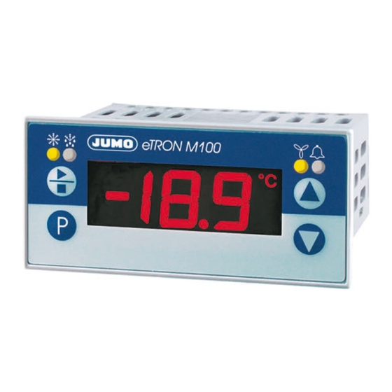
Electronic Refrigeration Controller
B 70.1061.0
Operating Instructions
2009-04-10
Related Manuals for JUMO eTron M 100
Summary of Contents for JUMO eTron M 100
-
Page 1
Electronic Refrigeration Controller B 70.1061.0 Operating Instructions 2009-04-10… -
Page 2
Overview of operation Process value display Cold store temperature (analog input 1) Code settable through Setup Evaporator temperature Display alternates > 3 seconds (analog input 2) increase decrease Residual time of current defrosting Parameter level All parameters can be altered here Operator level (no parameters enabled in factory setting) -
Page 3: Table Of Contents
Contents Identifying the instrument version ……….4 Mounting .
-
Page 4
5.10 Date and time …………. . . 30 5.11 Servicing, operating hours counter . -
Page 5
Contents… -
Page 6: Identifying The Instrument Version
2009-04-10 1 Identifying the instrument version Identifying the instrument version The nameplate is glued onto the housing top. The supply voltage must correspond to the voltage given on the nameplate. All necessary settings are described in these operating instructions. Any manipulations that are not described in the operating instructions (or even expressly forbidden) will endanger your rights under the instrument warranty ! If you have any problems, please contact the nearest subsidiary or the head office.
-
Page 7
701061 Basic version with 2 analog inputs and 3 relay outputs Basic type extensions factory-set, configurable configuration to customer specification Option 1 not available alarm buzzer alarm contact, changeover (SPDT) 16A/250V Option 2 not available RS485 interface data logger, real-time clock and RS485 interface Supply voltage 12 —… -
Page 8: Mounting
2009-04-10 2 Mounting Mounting Pull mounting frame off the instrument. Insert the instrument from the front into the panel cut-out. Make sure that the bezel seal is seated correctly. From the back, push the mounting frame onto the instrument housing, compressing the spring clips until the lugs have evenly snapped into place top and bottom.
-
Page 9: Electrical Connection
Electrical connection 3.1 Installation notes The choice of cable, the installation, the fusing and the electrical connection must conform to the requirements of VDE 0100 “Regulations on the Installation of Power Circuits with Nominal Voltages below 1000 V” or the appropriate local regulations.
-
Page 10: Connection Diagram
2009-04-10 3 Electrical connection 3.3 Connection diagram 1. The electrical connection must only be carried out by qualified personnel. 2. For shock-hazard protection, the instrument must only be connected to extra-low voltages which comply with SELV or PELV definitions, because supply voltage and analog inputs are not electrically isolated from one another ! Type 701061/XXX-XX Option 1:…
-
Page 11: Commissioning The Instrument
Commissioning the instrument 4.1 Displays and controls LC display 3-character nine-segment display, 13 mm high, and symbols for the temperature unit, hr, min, and sec, with red background lighting. Once the supply is switched on, all the segments light up and stay on for 5 seconds.
-
Page 12: Process Value Display (After Switch-On)
2009-04-10 4 Commissioning the instrument Apply the supply voltage, all segments light up five seconds long (for testing the segments). When everything has been connected up correctly to the instrument, it will show the current temperature at analog input 1. With the Data logger option, is shown briefly after switching on.
-
Page 13: Canceling Editing
Acknowledge with , the value blinks , prompting your entry. Use the keys to set the value within the specified range. The longer the key is pressed, the faster the value will change. Acknowledge the setting with , the new value is stored, and the display again switches between parameter name and value.
-
Page 14: Parameter Level
2009-04-10 5 Parameter level Parameter level Where appropriate, the full parameter names have been added in brackets, to explain their abbreviated forms in the display. All parameters for the maximum expansion level are listed in the table below. Depending on the instrument version (see data sheet), parameters which are not required are switched out of display. Value range Parameter Meaning from…factory-set…to…
-
Page 15
Value range Parameter Meaning from…factory-set…to Ω Lead compensation resistance, analog input 1 (offset resistance 1) 0.0 … 0.0 … 99.9 This value serves to compensate the resistance of the probe cable; it is dependent on the cable length. For an optimum temperature measurement, the resistance value of the probe cable must be entered here. -
Page 16: Binary Input
2009-04-10 5 Parameter level Value range Parameter Meaning from…factory-set…to Ω Lead compensation resistance, analog input 2 (offset resistance 2) 0.0 … 0.0 … 99.9 This value serves to compensate the resistance of the probe cable; it is dependent on the cable length. For an optimum temperature measurement, the resistance value of the probe cable must be entered here.
-
Page 17: Controller
Value range Parameter Meaning from…factory-set…to 5.3 Controller Ex-factory, the controller is set to «Cooling». For the special “Cooling + Heating” function, the fan relay is used for heating. Contr. type (tyPe) with above/below measured value (e.g. probe break) 0, 1, 2 0 : Cooling contr.
-
Page 18
2009-04-10 5 Parameter level Value range Parameter Meaning from…factory-set…to Hysteresis 0.0…1.0…50.0 °C For cooling and freezing, the hysteresis lies above the selected setpoint. 0.0…1.8…90.0 °F For the “Cooling + Heating” function, the hysteresis is above or below the selected setpoint, like a window function. Cooling / Freezing Cooling and Heating T/°C… -
Page 19
Value range Parameter Meaning from…factory-set…to Minimum Here you can set the minimum time for which e. g. the cooling unit 0 … 999 sec switch-on time (relay ) must be switched on or remain switched off. (time on) Please refer to the manufacturer’s specifications for the cooling unit that is used. -
Page 20: Defrosting (Cyclic)
2009-04-10 5 Parameter level Value range Parameter Meaning from…factory-set…to 5.4 Defrosting (cyclic) Cooling operation Defrosting operation T/°C Analog input 2 Analog input 1 (evaporator) (cold store) SP = 8 °C The starting behavior after power ON depends on the controller type Relay and the Power on parameter…
-
Page 21
Value range Parameter Meaning from…factory-set…to Defrosting type EL, GAS EL = electrical/circulating air: The cooling relay is switched off, and the defrosting relay is energized to defrost the evaporator by means of heater bars or circulating warm air. GAS = hot-gas defrosting: In this case, the cooling relay remains switched on during defrosting. -
Page 22
2009-04-10 5 Parameter level Value range Parameter Meaning from…factory-set…to Defrosting duration 0: no time limit The relay is energized during the defrosting time. Depending on the defrosting type 0 …30… 999 d.tY that has been set, “electrical/circulating air” or “hot gas” is used for defrosting. minutes Defrosting ends when the following has occurred: 1. -
Page 23
Value range Parameter Meaning from…factory-set…to Time 1 Hours and minutes can be separated by a decimal point. switched off: off The digit behind the decimal point represents a 10-minute step. 0.0… 23.5 hrs (defrosting time 1) Example: 23.5 signifies: 23:50 hrs Time 2 0.1 signifies: 00:10 hrs (defrosting time 2) -
Page 24: Switching Behavior Of The Fan Function
2009-04-10 5 Parameter level 5.5 Switching behavior of the fan function Cooling operation T/°C Analog input 1 (cold store) SP = 8 °C Relay energized Cooling Cooling Cooling de-energized Defrosting operation Relay energized Defrosting de-energized Defrosting time Defrosting function:cyclic Cycle time : Analog input 2 Run-up/ (evaporator temperature)
-
Page 25
Value range Parameter Meaning from…factory-set…to Fan function (see picture above) 0, 1, 2 0: fan runs with relay only 1: fan runs continuously except for defrosting (relay 2: fan runs during cooling (relay ) or defrosting (relay Run-up/run-down delay of fan (Fan running function) off, on has the hysteresis F.Hy, remains generally locked during drip-off time. -
Page 26: Alarms
2009-04-10 5 Parameter level Value range Parameter Meaning from…factory-set…to Fan run-up delay after defrosting (Fan deLay) 0 …30… 99 minutes After defrosting, the activity of the fan relay will be delayed for the time that was set. This has a higher priority than the run-up delay activated through F.ru=on, which would possibly switch the fan on earlier.
-
Page 27
Value range Parameter Meaning from…factory-set…to Alarm signaling (ALarm Function) 0, 1, 2, 3, 0: Relay is energized (alarm buzzer ON), with absolute alarm limits 1: Relay is de-energized (alarm buzzer OFF), with absolute alarm limits Absolute temperatures AL.L and AL.H AL.F = 0 =1°C energized… -
Page 28
2009-04-10 5 Parameter level Value range Parameter Meaning from…factory-set…to Low alarm limit (ALarm Low) For AL.F = 0 and 1: If the process value at the analog input 1 (in.1, cold store) goes below this limit: -200 … -50 … +500 °C 1. -
Page 29: Lc Display
Value range Parameter Meaning from…factory-set…to Alarm suppression time (ALarm delay time) 0 …5… 999 min An alarm from is suppressed in the display for this time, the relay or the alarm buzzer is also inactive. If an alarm is present for longer than , then it is displayed and the relay the alarm buzzer is active.
-
Page 30: Interface
Alarm display (display Alarm) off, on off: do not display alarms on: display alarms 5.8 Interface B 70.1061.2 Interface description on CD und www.jumo.net Device address 1…255 Data format 0, 1, 2, 3 0 means: 8 data bits, 1 stop bit, no parity…
-
Page 31: Data Logger
Value range Parameter Meaning from…factory-set…to Baud rate 9.6, 19.2, 38.4 9.6 means: 9600 bps 19.2 means: 19200 bps 38.4 means: 38400 bps 5.9 Data logger The data logger saves 11263 data sets to a ring memory which overwrites the oldest data with the most recent ones when the memory is full.
-
Page 32: Date And Time
2009-04-10 5 Parameter level Value range Parameter Meaning from…factory-set…to 5.10 Date and time Date Year 7…99 Millennium and century are permanently set to 20. The last two digits of the year can be adjusted. Date Month 1…12 Date Day 1…31 Date Hour 0…23 Date Minute…
-
Page 33: Servicing, Operating Hours Counter
Value range Parameter Meaning from…factory-set…to 5.11 Servicing, operating hours counter Time between services (timer Service interval) 0 … 999 days The time period after which the cooling unit is due for servicing (e.g. oil change or coolant test) is set here. The sum of all the active cooling-unit runtimes is saved here (i.e.
-
Page 34
2009-04-10 5 Parameter level Value range Parameter Meaning from…factory-set…to Current service counter for the connected cooling unit (timer Service counter) 0 … 999 days The sum of all the active cooling-unit runtimes is accumulated here (i.e. the times in over 24 hrs, days are which the cooling relay was energized) from those which have gone by since the last displayed: service. -
Page 35
5 Parameter level 2009-04-10… -
Page 36: Operator Level
2009-04-10 6 Operator level Operator level This level covers all parameters that are accessible (not locked by a code) to the operating personnel, for instance. Ex-factory, no parameters are available at this level. In the picture below, the parameters SP and HYS are configured at the operator level. Any parameter (up to eight
 can be enabled at this level through the setup program.
 -
Page 37: Technical Data
Technical data Analog input 1 Designation Measuring range Tolerance Detection of … and 2 in % of measuring range span, probe probe temperature effect short- break circuit RTDs Pt100 EN 60751 -200 to +600°C 0.05% (±0.4°C),100ppm/°C Pt1000 EN 60751 -200 to +600°C 0.05% (±0.4°C),100ppm/°C KTY1X-6 -50 to +100 °C…
-
Page 38
2009-04-10 7 Technical data Environmental influences Ambient temperature range 0 to +55°C Storage temperature range -40 to +70°C ≤85% rel. humidity, no condensation Climatic conditions Shock und vibration DIN EN 60068-2-6 schedule C.2, Frequency-Range: 10 to 55 Hz Acceleration: 20 m/s (2g) Care of the front panel The front panel can be cleaned with normal commercial washing, rinsing and cleaning… -
Page 39
Gold Cap capacitor buffers the clock time without a supply voltage for about 20 days. Technical and functional as per EN 12830 and EN 13485. characteristics of temperature recording devices or thermometers Approvals UL approvals are only valid for mass-production units with the JUMO symbol 7 Technical data 2009-04-10… -
Page 40: Setup Program
2009-04-10 7 Technical data 7.1 Setup program This program and the interface with adapter can be supplied as accessories. They offer the user the following advantages: easy and convenient parameterization and archiving from a PC simple duplication of parameters for instruments of the same type entry of a linearization table reading out data sets from the data logger.
-
Page 41: Transferring Measurements From The Data Logger To The Pc
7.4 Transferring measurements from the data logger to the PC The data logger saves 11263 data sets to a ring memory which overwrites the oldest data with the most recent ones when the memory is full. Transfer data from device Choose data logger Click OK, the data will be read out Click table view, the table on the right will be shown…
-
Page 42: Processing Measurements In Excel 1
2009-04-10 7 Technical data 7.5 Processing measurements in Excel Execute Extras => data logger => Save in menu bar Enter Semicolon as a separator Click Save as Save as 01_02_07.txt Execute File => Open in the Excel menu bar Select all files, otherwise the txt file will not be shown in the selection window Select 01_02_07.txt Even if the wizard comes up with an error message, clicking OK will start the text conversion wizard.
-
Page 43
Tab stop and semicolon must have a check mark Click Continue and enter a point as a separator, instead of the comma 7 Technical data 2009-04-10… -
Page 44
2009-04-10 7 Technical data The table can now be processed in Excel and saved in the Excel file format (.xls). -
Page 45: Alarm And Error Messages
Alarm and error messages The following alarm messages can be shown in alternation with the temperature display: Alarm display Cause Remedy Service interval run down Carry out service The selected time for the maintenance At the parameter level, reset manually to 0 of a heating or cooling unit has run down Chapter 4 “Commissioning the instrument”…
-
Page 46
2009-04-10 8 Alarm and error messages Error message Cause Remedy Gone above measured value Check probe and connecting cable for damage or The measured value is too large, is short-circuit outside the measurement range, or a Check whether the correct probe has been set or probe break has occurred. -
Page 47: Troubleshooting
The flash memory of the data logger The instrument must be returned to JUMO for repair. is faulty. The chip for the real-time clock is faulty. 8.1 Troubleshooting What is happening? Cause / Remedy Information Communication with the unit inter- Interface settings of the unit and PC do Chapter 7.1 “Setup program”…
-
Page 48
JUMO GmbH & Co. KG JUMO Instrument Co. Ltd. JUMO Process Control, Inc. Street adress: JUMO House 8 Technology Boulevard Moritz-Juchheim-Straße 1 Temple Bank, Riverway Canastota, NY 13032, USA 36039 Fulda, Germany Harlow, Essex CM20 2TT, UK Phone: 315-697-JUMO Delivery address:…
 can be enabled at this level through the setup program.
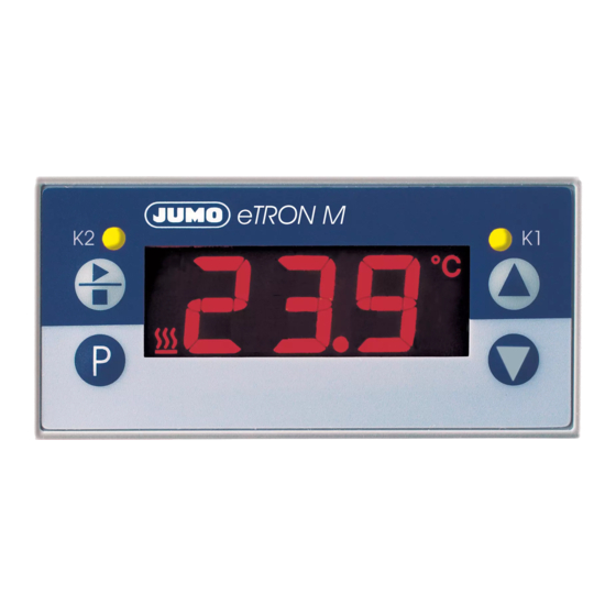
-
Contents
-
Table of Contents
-
Bookmarks
Quick Links
Elektronischer Microstat
Electronic Microstat
Microstat électronique
B 70.1060.0
Betriebsanleitung
Operating Instructions
Notice de mise en service
09.07/00440450
Related Manuals for JUMO eTRON M
Summary of Contents for JUMO eTRON M
-
Page 1
Elektronischer Microstat Electronic Microstat Microstat électronique B 70.1060.0 Betriebsanleitung Operating Instructions Notice de mise en service 09.07/00440450… -
Page 2
Funktionsübersicht Anzeige wechselt > 3 Sekunden Istwertanzeige Sekunden Timeout oder (Gleichzeitig) Code eingeben vergrößern vergrößern verkleinern verkleinern oder 30 Sekunden Timeout Bedienerebene Parameterebene Freigabeebene Parameter, die in der Freigabe- Hier können werkseitig voreinge- Parameter festlegen, die in der ebene ausgewählt wurden. stellte Parameter verändert Bedienerebene angezeigt werden werden. -
Page 3: Table Of Contents
Inhalt Geräteausführung identifizieren ……….4 Montage .
-
Page 4: Geräteausführung Identifizieren
Benutzer jederzeit zugänglichen Platz auf. Bitte unterstützen Sie uns, diese Betriebs- anleitung zu verbessern. Bei technischen Rückfragen Service-Hotline: Telefon: +49 661 6003-300 oder +49 661 6003-653 Telefax: +49 661 6003-9696300 oder +49 661 6003-881653 E-Mail: Service@jumo.net Lieferumfang 1 Dichtung 1 Befestigungsrahmen 1 Betriebsanleitung 70.1060.0…
-
Page 5
(1) Grundausführung 701060/ JUMO eTRON M (2) Grundtypergänzung Ausführung werkseitig eingestellt, konfigurierbar innerhalb der Messeingangsgruppe nach Kundenangaben konfiguriert Messeingangsgruppe Pt 100 in Zweileiterschaltung Pt 1000 in Zweileiterschaltung KTY2X-6 Fe-CuNi „J“ Fe-CuNi „L“ NiCr-Ni „K“ 0 … 20 mA 4 … 20 mA 0 … -
Page 6: Montage
Montage Befestigungs- rahmen 68,5 Rastnasen 76mm x 36mm Frontrahmenmaß +2,5 Schalttafelausschnitt mm x 28,5 Dicht-an-dicht-Einbau Abstand der Geräte: bis max. 40°C 10 mm horizontal Umgebungstemperatur: 15 mm vertikal Federbügel Befestigungsrahmen vom Gerät abziehen. Gerät von vorne in den Schalttafelausschnitt einsetzen und auf korrekten Sitz der Frontrahmendichtung achten. Befestigungsrahmen von hinten auf Gehäuse aufschieben, bis die Federbügel unter Spannung stehen und die Rastnasen oben und unten eingerastet sind.
-
Page 7: Elektrischer Anschluss
Elektrischer Anschluss 3.1 Installationshinweise Bei der Wahl des Leitungsmaterials, bei der Installation, bei der Absicherung und beim elektrischen Anschluss des Gerätes sind die Vorschriften der VDE 0100 „Bestimmungen über das Errichten von Starkstromanlagen mit Nennspan- nungen unter 1000 V“ oder die jeweiligen Landesvorschriften zu beachten. Der elektrische Anschluss darf nur von Fachpersonal durchgeführt werden.
-
Page 8: Anschlussplan
3.2 Anschlussplan Der elektrische Anschluss darf nur von Fachpersonal durchgeführt werden!
-
Page 9: Gerät In Betrieb Nehmen
Gerät in Betrieb nehmen 4.1 Anzeige- und Bedienelemente LC-Display 13 mm hohe dreistellige Neunsegmentanzeige und Symbole für Temperatureinheit, h, min, s, Abtauen und Heizen mit roter Hintergrundbeleuchtung. LED K1, K2 LED K1/K2 leuchtet, wenn das Relais K1/K2 angezogen ist. LED K1/K2 erlischt, wenn das Relais K1/K2 abfällt. Tasten für Start-Stopp im Heiz- und Kühlbetrieb…
-
Page 10: Gerätefunktionen Einstellen (Parameterebene)
4.2 Gerätefunktionen einstellen (Parameterebene) Timeout: Wird 60 Sekunden lang keine Taste bedient, schaltet das Gerät automatisch in die Istwertanzeige zurück, siehe Funktionsübersicht auf der ersten Innenseite. In der Parameterebene werden Gerätefunktionen und Werte eingestellt. Taste 3 Sekunden lang drücken und es erscheint abwechselnd Code 72 für den Zugang zur Parameterebene mit den Tasten einstellen.
-
Page 11
Regler Wertebereich Parameter Bedeutung von…werkseitig…bis Sollwert … 0.0 … Auf diesen Wert wird geregelt (Temperaturwert, Strom oder Spannung) Hysterese 0.2 … 1.0 … 99.9 Kühlen Heizen T/°C T/°C SP = 70 °C 69 °C SP = 8 °C Relais K1 Relais K1 angezogen angezogen… -
Page 12
Wertebereich Parameter Bedeutung von…werkseitig…bis Minimale Hier kann eingestellt werden, wie lange z. B. das Aggre- 0 … 999 s Einschaltdauer gat mindestens ein- oder ausgeschaltet bleiben muss. Diese Angaben sind abhängig vom verwendeten Heiz- Minimale 0 … 999 s oder Kühlgerät (Herstellerangaben beachten). Ausschaltdauer Bei Fühlerfehler wird das Relais, wie im Parameter S.Er eingestellt, sofort angesteuert. -
Page 13
Wertebereich Parameter Bedeutung von…werkseitig…bis aktuelle Restlaufzeit 999h … 2h, 120min … 2min, z.B. des Kühlbetriebs, Heizbetriebs usw. 120s … 0s, Heizregler Bei der Einstellung Heizbetrieb beenden Heizbetrieb starten >1 s mit Taste mit Taste >1 s Heizen ohne kein Zeitbegrenzung ti.0 = Heizbetrieb Heizbetrieb… -
Page 14
Wertebereich Parameter Bedeutung von…werkseitig…bis Verhalten nach Netz-Ein 0, 1 Kühlregler Heizregler Abtauen Heizen Aus Kühlbetrieb Heizbetrieb 0, 1, 2, 3 Freigabe der Start-Stop-Taste 0: gesperrt 2: Quittierung für Relais 2 (K2) 1: freigegeben 3: Start/Stop freigegeben und Quittierung Relais 2 Funktion des Relais K2 0 … -
Page 15
Wertebereich Parameter Bedeutung von…werkseitig…bis Alarme unterer Alarmgrenzwert -999 … -200 … +999 Unterschreitet der Istwert während des Heiz- oder Kühlbetriebes diese Grenze, wird die Alarmmeldung in der Anzeige ausgegeben, siehe Kapitel 7 „Alarmmeldungen“. Bei r 2= 1 oder 2 schaltet auch Relais K2. oberer Alarmgrenzwert -999 … -
Page 16
Wertebereich Parameter Bedeutung von…werkseitig…bis Eingang Angeschlossener Messwertgeber in Zweileiterschaltung Pt 100: Pt 1000: Messeingangsgruppe 1 bei Typ: 701060/X1X-XX KTY2X-6: oder Messeingangsgruppe 2 bei Typ: 701060/X2X-XX Fe-CuNi „J“: Fe-CuNi „L“: NiCr-Ni „K“: oder Messeingangsgruppe 3 bei Typ: 701060/X3X-XX 0(4)… 20 mA: Messeingangsgruppe 4 bei Typ: 701060/X4X-XX 0 … -
Page 17
Wertebereich Parameter Bedeutung von…werkseitig…bis Ω Leitungsabgleichwiderstand 0,0 … 0,0 … 99,9 Dieser Wert dient zur Kompensation des Widerstands der Fühlerleitung bei Widerstands-Messwertgebern und ist abhängig von der Leitungslänge. Für eine bestmögliche Temperaturmessung muss hier der ohmsche Wider- stand der Fühlerleitung eingegeben werden. Wenn der Gesamtwiderstand am Messeingang (Messwertgeberwider- Ω… -
Page 18: Bedienrechte Vergeben (Freigabeebene)
4.3 Bedienrechte vergeben (Freigabeebene) Die Einstellung in der Freigabeebene legt Bedienrechte fest, die darüber entscheiden, ob ein Parameter in der Be- dienebene erscheint, editiert werden kann oder gar nicht erscheint. Taste 3 Sekunden lang drücken und erscheint. Code 82 für den Zugang zur Freigabeebene mit den Tasten einstellen.
-
Page 19: Bedienen
Bedienen Sollwert und weitere Parameter ändern Kühlregler Istwertanzeige 1 Sekunde Abtaubetrieb Kühlbetrieb Heizregler Sollwert 1 Sekunde Heizbetrieb Heizen Aus Softwareversion anzeigen Weitere Parameter anzeigen (gleichzeitig) (je nach eingestelltem Bedienrecht (Beispiel) in der Freigabeebene)
-
Page 20: Technische Daten
Technische Daten Messeingang Bezeichnung Messbereich Messgenauigkeit Erkennung von … Umgebungstempe- Fühlerkurz- Fühlerbruch ratureinfluss schluss 0,1%/ ≤100ppm/K Widerstands- Pt 100 DIN EN 60751 -200 … +600°C thermometer 0,1%/ ≤100ppm/K Pt 1000 DIN EN 60751 -200 … +600°C 1%/ ≤100ppm/K KTY2X-6 (PTC) -50 …
-
Page 21
Messeingang Bezeichnung Messbereich Messgenauigkeit Erkennung von … Umgebungstempe- Fühlerkurz- Fühlerbruch ratureinfluss schluss 0,1%/ ≤100ppm/K Strom 0 … 20 mA -2 … 22 mA nein nein skalierbar mit oder Kundentabelle 0,1%/ ≤100ppm/K 4 … 20 mA 2,4 … 21,6 mA skalierbar mit ≤… -
Page 22
Reinigung und Pflege Die Frontplatte kann mit handelsüblichem Wasch-, Spül- und Reinigungsmitteln der Frontplatte gesäubert werden. Kein Lösungsmittel, wie z. B. Spiritus, Waschbenzin, P1 oder Xylol, verwenden. Ausgang 1 Relais (Wechselkontakt) 150.000 Schaltungen bei AC 250V/10A, 50Hz ohmsche Last bei Typ 701060/XX1-XX 2 Relais (Schließkontak) 100.000 Schaltungen bei AC 250V/5A, 50Hz ohmsche Last bei Typ 701060/XX2-XX… -
Page 23: Setup Programm
Elektrische Daten Datensicherung EEPROM Anschlussart Schraubklemmen für Drahtquerschnitte bis max. 4 mm eindrähtig und bis max. 2,5 mm feinstdrähtig. Elektromagnetische Verträglichkeit EN 61326 Störaussendung Klasse B Störfestigkeit Industrieanforderung Einsatzbedingungen Das Gerät ist als Einbaugerät ausgelegt. Elektrische Sicherheit DIN EN 61 010, Teil 1, Überspannungskategorie III, Verschmutzungsgrad 2 Ganggenauigkeit Timer 2,5 min/Monat, Temperatureinfluss 10ppm/10K 6.1 Setup Programm…
-
Page 24: Alarmmeldungen
Alarmmeldungen In der Temperaturanzeige können folgende Alarmmeldungen angezeigt werden: Fehleranzeige Ursache Abhilfe Anzeigeüberlauf Sensor und Anschlussleitung auf Beschädi- Der Messwert ist zu groß und liegt gung oder Kurzschluss überprüfen außerhalb des Messbereichs. Überprüfen, ob der richtige Sensor einge- stellt oder angeschlossen ist Anzeigeunterlauf Der Messwert ist zu klein und liegt Kapitel 4 „Gerät in Betrieb nehmen“…
-
Page 26
JUMO GmbH & Co. KG JUMO JUMO Mess- und Regelgeräte Ges.m.b.H. Mess- und Regeltechnik AG Hausadresse: Moltkestraße 13 — 31 Pfarrgasse 48 Laubisrütistrasse 70 36039 Fulda, Germany 1232 Wien, Austria 8712 Stäfa, Switzerland Lieferadresse: Telefon: +43 1 610610 Telefon: +41 44 928 24 44 Mackenrodtstraße 14… -
Page 27
Electronic Microstat B 70.1060.0 Operating Instructions 09.07… -
Page 28
Overview of operation… -
Page 29
Contents Instrument identification ……….. 4 Mounting . -
Page 30: Instrument Identification
Instrument identification The nameplate is affixed to the bottom of the instrument. The supply voltage that is connected must correspond to the voltage specified on the nameplate. All necessary settings are described in these Operating Instructions. If any difficulties should still arise dur- ing start-up, you are asked not to carry out any unauthorized manipulation on the unit.
-
Page 31
(1) Basic version 701060/ JUMO eTRON M (2) Basic type extension Version factory-set, configurable within the measurement input group configuration to customer specification Measurement input group Pt100 in 2-wire circuit Pt1000 in 2-wire circuit KTY2X-6 Fe-Con J Fe-Con L NiCr-Ni K 0 —… -
Page 32: Mounting
Mounting Pull off mounting frame from instrument. Insert the instrument from the front into the panel cut-out and make sure that the bezel seal is seated correctly. From the back, push mounting frame onto the housing until the spring clips are under tension and the snap-in lugs have engaged at top and bottom.
-
Page 33: Electrical Connection
Electrical connection 3.1 Installation notes The choice of cable, the installation, the fusing and the electrical connection must conform to the requirements of VDE 0100 “Regulations on the Installation of Power Circuits with nominal voltages below 1000 V” or the appropriate local regulations.
-
Page 34: Connection Diagram
3.2 Connection diagram electrical connection must only be carried out by qualified personnel!
-
Page 35: Commissioning The Instrument
Commissioning the instrument 4.1 Displays and controls LC display 3-digit 9-segment display, 13 mm high, and symbols for the temperature unit, h, min, s, defrosting and heating, with red background lighting. LED K1, K2 LED K1/K2 lights up when relay K1/K2 is energized. LED K1/K2 goes out when relay K1/K2 is de-energized.
-
Page 36: Setting The Instrument Functions (Parameter Level)
4.2 Setting the instrument functions (parameter level) Time-out: If no key is pressed for 60 seconds, the instrument automatically switches back to the process value display, see Overview of operation on the front inside page. The instrument functions and values are set at the parameter level. Press the key for 3 seconds and will appear alternately.
-
Page 37
Controller Value range Parameter Meaning from…factory-set…to Setpoint … 0.0 … target value of control action (temperature value, current or voltage) Hysteresis 0.2 … 1.0 … 99.9 Low setpoint limit -999 … -50 … +999 SP can be set down to this low limit. High setpoint limit -999 … -
Page 38
Value range Parameter Meaning from…factory-set…to Minimum Here you can set the minimum time for which the equip- 0 … 999 s ON time ment unit, for instance, has to remain switched on or off. These values depend on the heating or cooling unit used Minimum 0 … -
Page 39
Value range Parameter Meaning from…factory-set…to Currently remaining running time 999h … 2h, 120min … 2min, e.g. for cooling/heating operation etc. 120s … 0s, With setting t. i cannot be edited Service interval 0 … 999h … 9.9t h The time period after which the equipment unit has to be serviced is set here. -
Page 40
Value range Parameter Meaning from…factory-set…to Response after power-on 0, 1 Cooling contrl. Heating contrl. Defrosting Heating OFF Cooling Heating 0, 1, 2, 3 Enabling the start-stop key 0: inhibited 2: acknowledgement for relay 2 (K2) 1: enabled 3: start/stop enabled and acknowledgement relay 2 Function of relay K2 0 … -
Page 41
Value range Parameter Meaning from…factory-set…to Alarms Low alarm limit -999 … -200 … +999 If the process value falls below this limit during heating or cooling operation, the alarm message is output to the display, see Chapter 7 “Alarm messages”. If r 2= 1 or 2, relay K2 will also switch. High alarm limit -999 … -
Page 42
Value range Parameter Meaning from…factory-set…to Input Sensor connected in 2-wire circuit Pt100: Pt1000: Measurement input group 1 on Type: 701060/X1X-XX KTY2X-6: Measurement input group 2 on Type: 701060/X2X-XX Fe-Con J: Fe-Con L: NiCr-Ni K: Measurement input group 3 on Type: 701060/X3X-XX 0(4)… -
Page 43
Value range Parameter Meaning from…factory-set…to Ω Lead compensation resistance 0.0 … 0.0 … 99.9 This value is used to compensate the resistance of the probe lead for resi- tance sensors and is dependent on the lead length. For best temperature measurement results, the resistance value of the probe lead has to be entered here. -
Page 44: Allocating User Rights (Enabling Level)
4.3 Allocating user rights (enabling level) The setting at the enabling level defines user rights which determine whether a parameter is shown at the operating level, can be edited or is not shown at all. Press for 3 seconds and appears.
-
Page 45: Operation
Operation…
-
Page 46: Technical Data
Technical data Meas. input Designation Meas. range Meas. accuracy Recognition of … ambient tempera- Probe short- Probe break ture error circuit 0.1%/ ≤100ppm/°C Resistance Pt100 EN 60 751 -200 to +600°C thermometer 0.1%/ ≤100ppm/°C Pt1000 EN 60 751 -200 to +600°C 1%/ ≤100ppm/°C KTY2X-6 (PTC) -50 to +150 °C…
-
Page 47
Meas. input Designation Meas. range Meas. accuracy Recognition of … ambient tempera- Probe short- Probe break ture error circuit 0.1%/ ≤100ppm/°C Current 0 to 20 mA -2 to 22 mA scalable with or customer table 0.1%/ ≤100ppm/°C 4 to 20 mA 2.4 to 21.6 mA scalable with ≤… -
Page 48
Cleaning and care of the The front panel can be cleaned with all the usual cleaning and rinsing agents. front panel Do not use solvents such as methylated spirit, white spirit, P1 or xylene. Output 1 relay (changeover contact) 150,000 operations at 10A 250V AC, 50Hz resistive load on Type 701060/XX1-XX 2 relays (make contacts) 100,000 operations at 5A 250V AC, 50Hz resistive load… -
Page 49: Setup Program
Electrical data Data backup EEPROM Connection screw terminals for wire cross-sections up to 4 mm solid wire and up to 2.5 mm stranded wire Electromagnetic compatibility EN 61326 interference emission Class B immunity to interference to industrial requirements Operating conditions The instrument is designed as a panel-mounting unit.
-
Page 50: Alarm Messages
Alarm messages The following alarm messages may appear in the temperature display: Error message Cause Elimination Display overrun Check sensor and connecting cable for The measured value is too large and damage or short-circuit outside the range. Check whether the correct sensor has been set or connected Display underrun The measured value is too small and…
-
Page 52
JUMO GmbH & Co. KG JUMO Instrument Co. Ltd. JUMO Process Control, Inc. Street adress: JUMO House 8 Technology Boulevard Moltkestraße 13 — 31 Temple Bank, Riverway Canastota, NY 13032, USA 36039 Fulda, Germany Harlow, Essex CM20 2TT, UK Phone:… -
Page 53
Microstat électronique B 70.1060.0 Notice de mise en service 09.07… -
Page 54
Aperçu des fonctions l’affichage change > 3 secondes Affichage de la valeur réelle secondes timeout o (simultanément) saisir le code incrémenter incrémenter décrémenter décrémenter ou 30 secondes timeout Niveau Déverrouillage Niveau Utilisateur Niveau Paramétrage Paramètres On peut modifier ici Définir quels paramètres qui ont été… -
Page 55
Sommaire Identification de l’appareil ……….4 Montage . -
Page 56: Identification De L’appareil
03 87 37 53 00 Service de soutien à la vente : 0892 700 733 Télécopieur : 03 87 37 89 00 e-mail : info@jumo.net Matériel livré 1 joint 1 cadre de fixation 1 notice de mise en service 70.1060.0 Références de commande sur plaque…
-
Page 57
(1) Exécution de base 701060/ JUMO eTRON M (2) Extension du type de base Exécution Réglé en usine, configurable sur le groupe d’entrée de mesure Configuré en fonction des indications du client Groupe d’entrée de mesure Pt 100 en montage 2 fils… -
Page 58: Montage
Montage Cadre de fixation 68,5 Encoches Dimension du cadre avant 76 mm x 36 mm +2,5 Découpe du tableau mm x 28,5 Montage bord à bord Écart de l appareil : jusqu à max. 40 °C 10 mm horizontal de température ambiante 15 mm vertical Étrier à…
-
Page 59: Raccordement Électrique
Raccordement électrique 3.1 Instructions relatives à l’installation Aussi bien pour le choix du matériau des câbles, pour l’installation que pour le raccordement électrique de l’appareil, il faut respecter la réglementation en vigueur. Le raccordement électrique doit être effectué exclusivement par du personnel qualifié. La compatibilité…
-
Page 60: Schéma De Raccordement
3.2 Schéma de raccordement Le raccordement électrique doit être effectué exclusivement par du personnel qualifié. Pas de séparation galvanique entre entrée de mesure Type 701060/XX1-XX Pas de séparation galvanique entre entrée de mesure Type 701060/XX2-XX et alimentation pour type 701060/XX1-31 ! et alimentation pour type 701060/XX2-31 ! Relais K1 Relais K1…
-
Page 61: Mise En Service De L’appareil
Mise en service de l’appareil 4.1 Affichage et commande Indicateur Indicateur à 3 chiffres, de 13 mm de haut, avec des symboles pour unité de température, h, mn, s, dégivrage et chauffage avec rétro-éclairage rouge. LED K1, K2 LED K1/K2 est allumée lorsque le relais K1/K2 est excité. LED K1/K2 est éteinte lorsque le relais K1/K2 est au repos.
-
Page 62: Réglage Des Fonctions De L’appareil (Niveau Paramétrage)
4.2 Réglage des fonctions de l’appareil (niveau Paramétrage) Timeout : si aucune touche n’est actionnée pendant 60 s, l’appareil revient automatiquement à l’affichage de la valeur réelle, voir Aperçu des fonctions au dos de la couverture de la notice. Le niveau Paramétrage permet de régler les fonctions de l’appareil et des valeurs. Appuyez pendant 3 s sur la touche est affiché…
-
Page 63
Régulateur Plage de valeur Paramètre Signification … à … (réglage d’usine) Consigne à (0.0) Régulation à cette valeur (valeur de température, courant ou tension) Hystérésis 0.2 à 99.9 (1.0) Chaud Froid T/°C T/°C SP = 70 °C 69 °C SP = 8 °C Relais K1 Relais K1 excité… -
Page 64
Plage de valeur Paramètre Signification … à … (réglage d’usine) Temps Il est possible de régler ici la durée minimale pendant 0 à 999 s d’activation laquelle l’unité doit rester activée ou désactivée. Ces don- min. nées dépendent du dispositif de chauffage ou de refroi- dissement utilisé… -
Page 65
Plage de valeur Paramètre Signification … à … (réglage d’usine) Cycle de répétition du dégivrage 1 à 999 h (24) Uniquement pour le régulateur Froid (Col) Temps de fonctionnement restant 999 h à 2 h, 120 mn à 2 mn, Par ex. -
Page 66
Plage de valeur Paramètre Signification … à … (réglage d’usine) Affichage du total des heures de fonctionnement 0 à 999 h, 9,9 jours h Durée d’activité du relais pour l’entretien des unités (de chauffage ou de refroidissement). Affichage de la température pendant le dégivrage 0, 1 Geler la valeur de température pendant le dégivrage : 0 Actualiser en permanence la valeur de température : 1… -
Page 67
Plage de valeur Paramètre Signification … à … (réglage d’usine) Fonction du relais K2 0 à 6 Sans fonction : 0 Message d’erreur en souffrance : 1 Relais excité / 2 Relais au repos Message du timer : 3 Relais excité / 4 Relais au repos Intervalle d’intervention écoulé… -
Page 68
Plage de valeur Paramètre Signification … à … (réglage d’usine) −999 à +999 (500) Seuil d’alarme supérieur Pendant le mode Chaud ou Froid, si la valeur réelle est supérieure à ce seuil, le message d’erreur est affiché, voir Chapitre 7 “Messages d’erreur”. -
Page 69
Plage de valeur Paramètre Signification … à … (réglage d’usine) Entrée Capteur raccordé en montage 2 fils Pt 100 : Pt 1000 : Groupe d’entrée de mesure 1 pour type : 701060/X1X-XX KTY2X-6 : Groupe d’entrée de mesure 2 pour type : 701060/X2X-XX Fe-CuNi “J”… -
Page 70
Plage de valeur Paramètre Signification … à … (réglage d’usine) Ω Résistance de tarage de ligne 0,0 à 99,9 (0,0) Cette valeur sert à compenser la résistance de ligne de la sonde pour les capteurs à résistance, elle dépend de la longueur de la ligne. Pour que la mesure de température soit la meilleure possible, il faut saisir ici la résistance ohmique de la ligne de la sonde. -
Page 71: Attribution Des Droits D’accès (Niveau Déverrouillage)
4.3 Attribution des droits d’accès (niveau Déverrouillage) Les réglages au niveau Déverrouillage fixe les droits d’accès aux différents paramètres ; c’est-à-dire si un paramètre apparaît au niveau Utilisateur, s’il peut être édité ou s’il n’apparaît pas du tout. Appuyez pendant 3 s sur la touche apparaît.
-
Page 72: Commande
Commande Modifier consigne et autres paramètres Régulateur Froid Affichage de la valeur réelle 1 seconde Mode dégivrage Mode Froid Régulateur Chaud Consigne 1 seconde Mode Chaud Chauffage arrêté Afficher la version du logiciel Afficher autres paramètres (simultanément) (selon droits d’accès réglés (exemple) au niveau Déverrouillage)
-
Page 73: Caractéristiques Techniques
Caractéristiques techniques Entrée Désignation Étendue Précision de Détection de … de mesure de mesure mesure Court-circuit Rupture Influence de la de sonde de sonde température ambiante −200 à +600 °C 0,1%/ ≤100 ppm/K Sonde Pt 100 EN 60751 à résistance −200 à…
-
Page 74
Entrée Désignation Étendue Précision de Détection de … de mesure de mesure mesure Court-circuit Rupture Influence de la de sonde de sonde température ambiante −2 à 22 mA 0,1%/ ≤100 ppm/K Courant 0 à 20 mA adaptation échelle avec ou tableau du client 0,1%/ ≤100 ppm/K 4 à… -
Page 75
−40 à +70 °C Plage de température de stockage Humidité relative ≤ 75%, sans condensation Résistance climatique Nettoyage et entretien Il est possible de nettoyer la face avant avec des produits de lavage et de rin- de la face avant çage usuels. -
Page 76: Logiciel Setup
Caractéristiques électriques Sauvegarde des données EEPROM Type de raccordement Bornes à vis pour fil de section jusqu’à max. 4 mm (unifilaire) et jusqu’à max. 2,5 mm (fil extra fin). Compatibilité électromagnétique EN 61326 Émission de parasites Classe B Résistance aux parasites Normes industrielles Conditions d’utilisation L’appareil est prévu pour être encastré.
-
Page 77: Messages D’erreur
Messages d’erreur L’afficheur de la température peut contenir les messages d’erreur suivants : Message d’erreur Cause Suppression Dépassement sup. capacité aff. Vérifier si la sonde et le câble de raccorde- La valeur mesurée est trop grande, ment sont endommagés ou en court-circuit elle est hors de l’étendue de mesure.
-
Page 78
Seuil d’alarme inférieur dépassé Selon le type de régulateur réglé, vérifier si val. réelle l’unité de chauffage ou de refroidissement fonctionne encore correctement. Vérifier si l’éventuel fusible de protection du Seuil d’alarme supérieur dépassé relais est encore bon. val. réelle L’alarme disparaît dès que la valeur réelle est inférieure au seuil AL.H moins l’hystérésis, ou supérieure au seuil AL.L plus l’hystérésis. -
Page 80
JUMO GmbH & Co. KG JUMO Régulation SAS Adresse : Actipôle Borny Moltkestraße 13 — 31 7 rue des Drapiers 36039 Fulda, Allemagne B.P. 45200 Adresse de livraison : 57075 Metz — Cedex 3, France Mackenrodtstraße 14 Téléphone : +33 3 87 37 53 00 36039 Fulda, Allemagne Télécopieur :…
* УТОЧНЯЙТЕ ВОЗМОЖНОСТЬ, ЦЕНУ И СРОК ПОСТАВКИ, В СВЯЗИ С ОГРАНИЧЕНИЕМ ЭКСПОРТА ТОВАРОВ ИЗ СТРАН ЕС И ВЕЛИКОБРИТАНИИ
- Описание и тех. спецификация
- Характеристики
- Способы доставки
eTRON M — Electronic Microstat
Jumo eTRON M digital electronic thermostat for simple temperature control (heating or cooling).
Compact, electronic microstat for simple temperature control (for heating or cooling)
Three-digit backlit LC display
13 mm digit height and special characters for °C, °F, h, min, s, active defrosting and/or heating phase
Simple operation via four keys
Input depending on type:
— Resistance thermometer
— Thermocouple
— Current
Output 1 changer or 2 N/O
Adjustable switching hysteresis
Integrated defrost function
Limit value monitoring
Elapsed time counter
Code-protected parameter level
Simple assembly, panel-mounted
Electr. connection via screw terminals
Sensor Pt100, protection tube 6 x 50 mm, connection lead 2.5 m, silicone, -50 °C → +180 °C
Setup program (for Windows 98/ME/NT4.0/2000/XP) incl. PC interface
Техническая спецификация ControlShipbuilding Industry
Напряжение питания:
230 В перем. тока
Рабочая температура — максимальная:
+55°C
Рабочая температура — минимальная:
0°C
Тип входа:
K тип Термопара
Тип монтажа:
Крепление на панель
| Самовывоз со склада поставщика в Екатеринбурге | Забираете сами или вызываете курьера |
| ТК Деловые Линии | от 500 руб |
| Курьером EMS Почта России | от 500 руб |
| Другой транспортной компанией | По согласованию |

JUMO ecoTRON T — это компактный цифровой электронный термостат для простого регулирования температуры (нагревания или охлаждения). Температура измеряется с помощью термометров сопротивления Pt100, Pt1000 или KTY2X-6, подключаемых по 2-проводной схеме, и отображается на 3-разрядном дисплее с фоновой подсветкой. Коммутационное состояние сигнализируется светодиодом.
Прибор имеет простую функцию разморозки и счетчик рабочего времени, позволюящий, например, определить время функционирования компрессора-охладителя. Прибором управляют с помощью 4 клавиш, расположенных на лицевой панели. Электричские соединения осуществляются с задней стороны прибора через винтовые зажимы.
Особенности
- Возможность конфигурирования режимов нагрева или охлаждения
- Регулируемый гистерезис
- Встроенная функция размораживания
- Счетчик рабочего времени
- Символы на дисплее для режима управления — °С, °F, ч, мин, с
- Уровень параметров защищен кодовым числом
- Индивидуальное разблокирование отдельных параметров для обслуживания
- Реле 10 А
- Простой компактный монтаж
- Программируемая задержка включения регулятора после подключения к сети, например, для включения отдельных приборов в разное время
- Допуск UL в процессе подготовки
Документы
.jpg)
Типовой лист 70.1060
- Аналогичные товары

Вся информация на сайте о товарах и ценах носит справочный характер и не является публичной офертой. Производитель оставляет за собой право изменять характеристики товара, его внешний вид и комплектность без предварительного уведомления продавца
Table of Contents for JUMO eTron M 100:
-
5 Parameter level 21 2013-05-01 Lead resistance compensation, analog input 1 This value serves to compensate the probe line resistance and depends on the line length. Enter the ohmic resistance of the probe line here to achieve the best tem- perature measurement possible. 0.0 … 0.0 … 99.9 Ω Probe on analog input 2 in 2-wire circuit means customer-specific linearisation, which is not provided in this device version. switched off: Pt 100: Pt 1000: KTY1X-6: KTY2X-6: or Offset temperature analog input 2 A
-
3 Electrical connection 2013-05-01 8 3.2 Connection diagram 16A/250V AC 1413 J 19 17 20 Supply voltage Analog input Pt100, Pt1000, KTY1X-6 or KTY2X-61 for (L-) (L+) 12 — 24 V AC/DC +15/-15 %, 48 — 63Hz 1121 5 8 7 12 15 18 21 22 23 24 S P S P Ö Binary input floating contact J Analog input 2 for Pt100, Pt1000, KTY1X-6 or KTY2X-6 S P 1. The switching positions of the instrument rela
-
Bedienübersicht Parameterebene Hier können alle Parameter verändert werden. Istwertanzeige > 3 Sekunden letzter Parameter vergrößern verkleinern Anzeige wechselt weitere Parameter je nach Gerätetyp P P (gleichzeitig) oder Timeout 60 s + P Analogeingang1 Analogeingang2 Code eingeben Anzeige wechselt Bedienerebene (werkseitig keine Parameter freigegeben) 8 Parameter können über Setup-Programm in diese Ebene gelegt werden. P (werkseitig 72)
-
8 Error messages 31 2013-05-01 8 Error messages Display Cause Remedy Measured value exceeded The measured value is too high, is outside the measuring range or the probe is broken. — Check the probe and connection line for damage or short-circuit. — Check that the correct probe is set and/or connected. v Chapter 4 „Commissioning/starting up the device“ Measured value underrange The measured value is too low,
-
5 Niveau Paramétrage 2013-05-01 16 5.3 Réglage du comportement du relais K3 Paramètre Signification Plage de valeurs de_à_(régl. usine) Votre réglage CoL : froid Si valeur réelle supérieure à la consigne et l’hystérésis, relais K3 excité. Si valeur réelle inférieure à la consigne, relais K3 au repos. Hot : chaud Si valeur réelle supérieure à la consigne, relais K3 au repos. Si valeur réelle
-
8 Fehlermeldungen 2013-05-01 32 8.1 Was tun, wenn … Was passiert ? Ursache/Abhilfe Info Parameter in.1 … in.4 erscheinen nicht in Parameterebene Einstellung für An.2 steht auf off. h In der Parameterebene An.2 wieder auf Pth oder auf denjenigen Sensor einstellen, der angeschlossen werden soll. v Kapitel 5.6 „Analogeingänge“
-
8 Fehlermeldungen 33 2013-05-01
-
4 Commissioning/starting up the device 9 2013-05-01 4 Commissioning/starting up the device 4.1 Display and operating elements LC display 13 mm high 3-digit nine-segment display and symbols for temperature, unit, h, min, and s with red background lighting. Once the voltage supply is switched on, all segments are lit permanently for 5 s. LED K1 LED is lit, once the respective relay is energized. LED extinguishes, once the
-
5 Parameterebene 2013-05-01 18 5.4 Schaltverhalten Relais K4 einstellen Ihre Ein- stellung Parameter Bedeutung Wertebereich von…werkseitig…bis CoL: Kühlen Beim Überschreiten des Sollwertes und der Hysterese zieht das Relais K4 an. Beim Unterschreiten des Sollwertes fällt das Relais K4 ab. Hot:: Heizen Beim Überschreiten des Sollwertes fällt das Relais K4 ab. Beim Unterschreiten des Sollwertes und der Hysterese zieht das Relais K4 an. CoL, Hot Sollwert für die Funk
-
5 Niveau Paramétrage 2013-05-01 20 5.5 Réglage de l’unité de température Paramètre Signification Plage de valeurs de_à_(régl. usine) Votre réglage Unité de température (Unit) pour les températures affichées °C ou °F 5.6 Entrées analogiques Paramètre Signification Plage de valeurs de_à_(régl. usine) Votre réglage Sonde sur l’entrée analogique 1 en montage 2 fils signifie Linéarisation spécifique au client qui n’est pas prévue sur cette exécution de l’appareil. Pt 100 : Pt 1000 : KTY1X-6
-
8 Messages d’erreur 31 2013-05-01 8 Messages d’erreur Affichage Cause Suppression Dépassement supérieur de la valeur mesurée La valeur mesurée est trop grande, elle est hors de l’étendue de mesure ou la sonde est coupée. — Vérifiez que la sonde et le câble de raccor- dement ne sont pas endommagés, ni en court-circuit. — Vérifiez que la bonne sonde est réglée ou raccordée. v Chapitre 4 « Mise en service de l’appareil » Dépassement inférieur de la valeur mesurée La valeur mesurée est
-
4 Gerät in Betrieb nehmen 9 2013-05-01 4 Gerät in Betrieb nehmen 4.1 Anzeige- und Bedienelemente LC-Display 13 mm hohe dreistellige Neunsegmentanzeige und Symbole für Tem- peratureinheit, h, min, und s mit roter Hintergrundbeleuchtung. Nach dem Einschalten der Spannungsversorgung leuchten alle Segmente 5s lang dauerhaft. LED K1 LED leuchtet, wenn das entsprechende Relais angezogen ist. LED erlischt, wenn das jeweilige Relais dafür abgefallen ist. LED K2 LED K3 LED K4 Tasten Programmi
Questions, Opinions and Exploitation Impressions:
You can ask a question, express your opinion or share our experience of JUMO eTron M 100 device using right now.