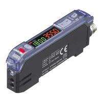
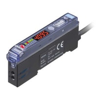
| Model | FS-V11P | |
| Type | Main unit | |
| Output | PNP | |
| Light source | Red LED | |
| Response time | 250 µs (FINE) /500 µs (TURBO) /1 ms (SUPER TURBO) | |
| Operation mode | LIGHT-ON/DARK-ON (switch-selectable) | |
| Indicator lamp | Display indicator: Red LED Digital LED monitor: Seven segments, four digits, red LED Bar LED monitor: One orange LED and six green LEDs |
|
| Timer function | ON-delay: 40 ms /OFF-delay: 10 ms /Timer OFF (switch-selectable) | |
| Control output | PNP open-collector 100 mA max. (24 VDC max.), Residual voltage: 1 V max. | |
| Protection circuit | Reversed polarity protection, over-current protection, surge absorber | |
| Unit expansion | Up to 16 expansion units can be connected (a total of 17 units).*1 | |
| Mutual interference suppression |
FINE : 4, TURBO/SUPER: 8 | |
| Rating | Power voltage | 12 to 24 VDC ±10 %, Ripple (P-P) 10 % or less*2 |
| Current consumption | 50 mA or less | |
| Environmental resistance | Ambient light | Incandescent lamp: 10,000 lux max., Sunlight: 20,000 lux max. |
| Ambient temperature | -10 to +55 °C (No freezing) | |
| Relative humidity | 35 to 85 % RH (No condensation) | |
| Vibration resistance | 10 to 55 Hz, Double amplitude 1.5 mm, 2 hours in each of the X, Y, and Z directions | |
| Shock resistance | 500 m/s2, 3 times in each of the X, Y, and Z directions | |
| Case material | Polycarbonate | |
| Weight | Approx. 80 g | |
| *1 If more than one unit is used together, the ambient temperature varies with the conditions below. Mount the units on the DIN rail with mounting brackets and check that the output current is 20 mA or less. 3 to 10 Units: -10 to 50°C, 11 to 16 Units: -10 to 45°C *2 Neither the FS-V12 nor the FS-V10 can be used as a standalone unit. |
Catalog
Manuals
| IV Series Instruction Manual | [File type] PDF :1.55MB | Download |
| IV Series Setup Guide Monitor (English) | [File type] PDF :1.36MB | Download |
| IV Series Setup Guide PC Software (English) | [File type] PDF :921KB | Download |
| IV Series Starting Guide (Monitor) | [File type] PDF :4.09MB | Download |
| IV Series Starting Guide (PC Software) | [File type] PDF :5.97MB | Download |
| IV Series User’s Manual (Field Network) | [File type] PDF :3.03MB | Download |
| IV-G/IV Series User’s Manual Monitor | [File type] PDF :13.83MB | Download |
| IV-G/IV Series User’s Manual [PC Software] | [File type] PDF :26.21MB | Download |
| IV-D10 Instruction Manual | [File type] PDF :599KB | Download |
| IV-G Series Instruction Manual | [File type] PDF :1.77MB | Download |
| IV-GD05/GD10 Instruction Manual | [File type] PDF :830KB | Download |
| IV-H Series Instruction Manual | [File type] PDF :1.62MB | Download |
| IV-H Series × ROCKWELL Compact Logix Connection Guide | [File type] PDF :3.97MB | Download |
| IV-H Series × ROCKWELL Control Logix Connection Guide | [File type] PDF :4.14MB | Download |
| IV-H Series × SIEMENS S7-1500 Series Connection Guide | [File type] PDF :3.24MB | Download |
| IV-H Series × SIEMENS S7-1200 Series Connection Guide | [File type] PDF :2.92MB | Download |
| IV-H1 Instruction Manual | [File type] PDF :1.9MB | Download |
| IV-HG Series Instruction Manual | [File type] PDF :1.73MB | Download |
| IV-HG/IV-H User’s Manual Field network | [File type] PDF :3.03MB | Download |
| IV-HG/IV-H User’s Manual Monitor | [File type] PDF :15.45MB | Download |
| IV-HG/IV-H Series User’s Manual [PC Software] | [File type] PDF :34.22MB | Download |
| IV-M30 Instruction Manual | [File type] PDF :2.07MB | Download |
| KV-7500/5500 × IV Series Ethernet/IP Connection Guide (English) | [File type] PDF :1.17MB | Download |
| OP-87436/87437 Instruction Manual | [File type] PDF :467KB | Download |
| OP-87461 Instruction Manual | [File type] PDF :355KB | Download |
| OP-87899/87900/87901/87902 Instruction Manual | [File type] PDF :603KB | Download |
Software
| IV Series Monitor (IV-M30) Update Firmware | [File type] zip :6.23MB | Download |
| IV Series Monitor (IV-M30) Update Firmware | [File type] zip :6.23MB | Download |
| IV Series Sensor (IV-150/500/2000) Update Software | [File type] zip :2.0MB | Download |
| IV Series Sensor (IV-150/500/2000) Update Software | [File type] zip :2.0MB | Download |
| IV-G Series Sensor (IV-G10/15) Update Software | [File type] zip :2.0MB | Download |
| IV Setting file for EtherNet/IP Network (EDS File) | [File type] zip :11KB | Download |
| IV Setting file for PROFINET Network (GSDML File) | [File type] zip :9KB | Download |
| IV PROFINET sample program for SIMATIC Manager | [File type] zip :374KB | Download |
| IV PROFINET sample program for TIA PORTAL | [File type] zip :370KB | Download |
| IV tag file for EtherNet/IP | [File type] zip :85KB | Download |
| IV-Navigator (IV-H1) Software |
For product users only. Serial number is required.
[File type] exe :765.69MB Download IV-Navigator (IV2-H1) Update Software [File type] exe :702.27MB Download [IV series]Setting file for sensor network(EZ1 File) [File type] zip :9KB Download [IV-H/G Series] Communication Unit Configuration File for KV STUDIO(ez1 file) [File type] zip :10KB Download
Quick Delivery and Comprehensive Support
KEYENCE supports customers from the selection process to line operations with on-site operating instructions and after-sales support.
KEYENCE CORPORATION OF AMERICA 500 Park Boulevard, Suite 200, Itasca,
IL 60143, U.S.A.
Phone: 1-888-KEYENCE [1-888-539-3623]
E-mail: tech@keyence.com Live Chat Now!
Career Opportunities: KEYENCE Career Site
Copyright (C) 2021 KEYENCE CORPORATION. All Rights Reserved.
Источник
Оптоволоконные датчики
Любой оптоволоконный датчик Keyence состоит из собственно оптоволокна и усилителя, выбор которых определяется решаемой задачей.
Мы предлагаем оптоволокно Keyence просвечивающего типа или с зеркальным отражением в широком диапазоне размеров и оптических изображений, углов изгиба, механической и химической стойкости, вариантов монтажа.
Все усилители Keyence серии FS работают совместно с волокнами серии FU и отличаются высокой мощностью и простотой настройки и монтажа.
Цифровые волоконно-оптические датчики Keyence
Датчики серии FS-V30
Датчики сверхвысокой мощности для суровых условий эксплуатации.
- Самый мощный в мире луч, в 64 раза более мощный, чем у обычных датчиков;
- самое короткое время отклика: 33мкс;
- первая в мире функция автоматического отслеживания значений;
- самый мощный усилитель;
- долгий срок службы.
Датчики серии FS-V20
Датчики сверхвысокой мощности с двух экранным усилителем для суровых условий эксплуатации.
- Самый мощный в мире луч, в 64 раза более мощный, чем у обычных датчиков;
- первый в отрасли двух экранный цифровой дисплей, позволяющий просматривать как предустановленные, так и текущие значения;
- короткое время отклика: от 50 мкс;
- простота и надежность функциональной компоновки;
- долгий срок службы.
Датчики серии FS-V10
Датчики с усилителем, поддерживающим проводку.
- Первая в отрасли система двойного мониторинга;
- автоматическая и ручная калибровка;
- наличие LED-индикаторов, отражающих количество принятых сигналов и уровень стабильности обнаружения;
- 20-битный параллельный процессор;
- высокая точность и мощность;
- проводная 0-строчная или 1-строчная система подключения.
Датчики серии FS-V/T/M
Датчики с усилителем, поддерживающим проводку.
- Три варианта калибровки: ручной, автоматический и гибридный;
- двойная система контроля с использованием LED-индикаторов;
- короткое время отклика: от 20 мкс;
- компактность исполнения и простота эксплуатации;
- 12-битный параллельный процессор;
- проводная 0-строчная или 1-строчная система подключения.
Датчики серии FS
Датчики кабельного типа с большим расстоянием обнаружения и 8-оборотным триммером.
Источник
Оптоволоконный датчик Keyence
Купить Оптоволоконный датчик Keyence в компании Олниса можно оптом или в розницу. Доставим Оптоволоконный датчик Keyence в любой регион России. Можем предложить точный аналог. Работаем напрямую с производителем, не используя посредников.
Последние несколько десятков лет автоматизация движется вперед с геометрической прогрессией. Благодаря этой тенденции значительно повысился спрос на различные датчики, которые способствуют автоматизации производства. Как следствие повысился спрос на фирмы, которые занимаются выпуском подобного оборудования. Одна из них японская компания Keyence, которая как раз специализируется на производстве подобных деталей.
- датчики различного типа;
- устройства на электронной основе;
- считыватели;
- сканеры.
Сегодня Keyence — это известный в мире поставщик электроники с 16 представительствами в разных странах.
Особенности оптоволоконных датчиков
Конструкция датчика Keyence очень простая. Он состоит из оптоволокна и собственно усилителя. За счет того, что изделия совершенно не зависят от электричества, они могут использоваться в любой среде.
Фактически датчик состоит из двух частей: приемника и излучателя. Между ними происходит передача световой волны. Обе части могут находиться либо в одном месте или двух разных.
Среди достоинств, которыми обладают эти датчики, нужно отметить:
- мультиплексирования;
- возможность дистанционного измерения;
- стойкость к электромагнитному полю;
- отсутствие необходимости использовать электричество;
- стабильность.
Для производства используются оптические волокна той же фирмы. Компания Keyence выпускает несколько серий датчиков:
- FS-N40 включает в себя усилитель одной из последних конструкций, OLED-экран, высокоинтеллектуальные технологии и мощность;
- FU — сенсорные головки разных видов и сложности исполнения;
- FS-N имеет новые технологии настройки, при помощи одной кнопки можно выполнить все настройки или сделать обнуление, обслуживается автоматически.
Для определения расстояния до объекта используется самый большой плюс оптоволокна — быстрое распределение света. Время отклика может составлять всего 33 мкс. Износостойкость материала достаточно высокая и потому датчики имеют длительный срок службы. Есть возможность запоминания значений, высокая точность измерений и применение в различных средах.
Где купить оптоволоконные датчики Keyence
ОЛНИСА — это мультибрендовая компания, которая занимается поставками электронного оборудования на просторах России и в странах СНГ. Фирма поставляет необходимые изделия непосредственно от производителей. Это позволяет предлагать клиентам очень приятные цены.
В каталоге сайта Олниса можно найти различных фирм-производителей. И сделать комплексный заказ. Здесь вам предложат:
- широкий ассортимент, как новой продукции, так и той, что уже снята с производства — это очень важно, когда необходимо просто произвести ремонт;
- простая и удобная система скидок для постоянных клиентов;
- возможность доставки на дом.
Основные условия заказа — он должен быть не менее 50 евро. Заказ может быть доставлен несколькими способами. Возможна также и экспресс-доставка. Производится она в течение одного дня.
Источник
Датчики KEYENCE
:format(png)/f89b73cd0c8aa77.s.siteapi.org/img/ff2abcdddac94d80745f5ab2a788eb4678627f65.png)
:format(png)/f89b73cd0c8aa77.s.siteapi.org/img/f871b0c84d0fd03aab825589178e853dd529319a.png)
:format(png)/f89b73cd0c8aa77.s.siteapi.org/img/2276a06aba2b3da340be01ffa46a81e82bae5102.PNG)
:format(png)/f89b73cd0c8aa77.s.siteapi.org/img/37d47363ea81fd716d54545cb31da2a39412a6a5.PNG)
:format(png)/f89b73cd0c8aa77.s.siteapi.org/img/37086d86aa0132a33e945c923f9d571c7bc22f5e.PNG)
:format(png)/f89b73cd0c8aa77.s.siteapi.org/img/97c1b85c9fae2f6ba7977b4efcad5ca03ee7a6d1.PNG)
:format(png)/f89b73cd0c8aa77.s.siteapi.org/img/38ef4538bfbfa1c03a6a7a289c0b1f9388befe71.PNG)
:format(png)/f89b73cd0c8aa77.s.siteapi.org/img/7ffa3f5c4e10f06217673e5935e3f5017e42cbfb.PNG)
:format(png)/f89b73cd0c8aa77.s.siteapi.org/img/1e3bf1c8c84d7533fc5783cddf72eab60ba200ff.PNG)
Чтобы избежать затруднений при выборе продукции K EYENCE , достаточно позвонить экспертам Центра Сенсорных Технологий Touch-Mall : +7 (495) 972-09-08 или отправить запрос по электронной почте info@touch-mall.ru или sales@touch-mall.ru
Продукты автоматизации K EYENCE
Датчики, лазерные маркеры и оборудование для обеспечения безопасности
K EYENCE разрабатывает продукты, которые помогают автоматизировать производственные процессы клиентов, экономя их время и деньги. Клиенты в самых разных отраслях промышленности используют универсальные датчики K EYENCE для обнаружения наличия или отсутствия деталей, а также измерения их характеристик. K EYENCE также производит датчики расхода, датчики давления, датчики температуры и статические выпрямители для улучшения процессов.
Лазерные маркеры K EYENCE используют 3-осевую технологию для маркировки номеров продуктов, логотипов, штрих-кодов и многого другого практически на любом материале и поверхности. Защитное оборудование K EYENCE от компании Touch-Mall включает защитные световые завесы и сканеры безопасности.
Как ведущий мировой поставщик датчиков, измерительных систем, лазерных маркеров, микроскопов и систем машинного зрения, K EYENCE находится в авангарде автоматизации производства. K EYENCE стремится разрабатывать инновационные и надежные продукты для удовлетворения потребностей клиентов во всех производственных отраслях.
Продукция K EYENCE предназначена для увеличения стоимости производственных и исследовательских процессов клиентов. Команда K EYENCE по исследованиям и разработкам постоянно стремится улучшать предлагаемые продукты, чтобы лучше соответствовать и превосходить ожидания клиентов. Продукты K EYENCE спроектированы так, чтобы быть универсальными, поэтому их можно использовать в любой отрасли и решать самые разные задачи.
1. Волоконно-оптический датчик
• Полная настройка в один клик
• 250x более мощные, чем обычные модели
Высокоскоростной 3-осевой лазер
• Типы маркировки волокна, CO2, YVO4 и зеленого лазера
• 3-осевая лазерная маркировка
• Высокоскоростной выход 30 или 50 Вт
Высокоскоростной и цифровой
• Самое высокое разрешение в своем классе (.01um)
• Высокая долговечность и устойчивость к суровым условиям
4. Световая завеса безопасности
Сверхмощный, без мертвой зоны
• Зона обнаружения от края до края
• Жесткая, водонепроницаемая модель
Инспекционные продукты K EYENCE
Машинное зрение, измерительные системы, микроскопы и считыватели кода
Проверка деталей на всех этапах производственного процесса имеет решающее значение для многих наших клиентов. K EYENCE предлагает широкий ассортимент продукции, используется на сборочной линии или в лаборатории.
В едущие в отрасли системы машинного зрения K EYENCE позволяют клиентам Touch-Mall точно и мгновенно выполнять визуальный контроль качества. Для высокоточных измерений K EYENCE предлагае т множество измерительных систем, позволяющих быстро определить, качество изготовленны х заказчиками детал ей .
1. Система машинного зрения
Сверхскоростная и гибкая система машинного зрения
• 11-кратная высокоскоростная камера с разрешением 5 миллионов пикселей
• Процессорная система 3 + 1: сверхскоростная параллельная обработка
Ультракомпактный цифровой считыватель штрих-кода
• Скорость декодирования 1300 / сек
• Шум и функции компенсации
• Функция автоматической калибровки
• Модели высокого разрешения и дальнего действия
3. Лазерный датчик смещения
Высокая скорость, высокая точность. Датчики смещения лазера
• Разрешение 0,0004 мил (0,01 мкм)
Изображения с высоким разрешением, 3D-профили, высшая глубина резкости.
• Большая глубина резкости: в 20 раз больше, чем у обычных микроскопов.
• Наблюдать, записывать и измерять — все с единой системой
• 0,1-5000x — д иапазон увеличения
Интуитивные датчики K EYENCE успешно используются во всех промышленных отраслях. Неоспоримые ПЛЮСЫ:
Эффективная автоматизация деятельности;
Повышение продуктивности процессов;
Экономия рабочих ресурсов и времени;
Корректные показатели даже в суровых климатических условиях.
Дистанционные и контактные с енсоры
При выборе оптимальных приборов для промышленности важно учесть их специфику и функциональность.
Три главных подразделения: л азерные КИП, многоцелевые ф отоэлектрические и в олоконно-оптические.
К новаторским разработкам относятся ультразвуковые и контактные системы позиционирования – они умеют обнаруживать объекты, недоступные обычным приборам.
Востребованы узкоспециализированные лазерные устройства и анализаторы RGB-цветов.
Принцип работы в у словиях промышленности
Все промышленные датчики бренда K EYENCE являются безупречными исполнителями. Такие элементы управления призваны преобразовывать подконтрольную величину в определенный сигнал. Полученные данные легко изучать, измерять, сохранять и передавать!
Принцип работы лазерного датчика и фотоэлектрической модели во многом идентичен. Лучи света выходят из передатчика и исследуют «цель», автоматика рассчитывает полученные данные и оповещает специалиста. Ультразвуковые бесконтактные сенсоры способны с высокой точностью рассказать о расстоянии и размерах объекта за счет деформации волн, выпускаемых из центра. Приборы давления оснащены чувствительным элементом, который перерабатывает собранную информацию в электрический формат.
Продукты K EYENCE призваны повысить ценность процессов производства и исследований клиентов.
Исследовательская команда и разработчики K EYENCE постоянно стремятся модернизировать технические характеристики оборудования, чтобы лучше соответствовать ожиданиям клиентов и превосходить их.
K EYENCE стремится предлагать лучшие в мире продукты на сегодня.завтрашние приложения.
Фотоэлектрические датчики K EYENCE
Автономные фотоэлектрические КИП
Self-contained CMOS Laser Sensor LR-Z series
Лазерный сенсор, способный обнаруживать цели на основе как положения, так и контраста (детектируемое расстояние: до 500 мм)
All — Purpose Laser Sensor LR-T series
Лазерный сенсор, способный к стабильному обнаружению независимо от цели (детектируемое расстояние: от 6 см до 5 м)
Self-Contained Full-Spectrum Sensor LR-W series
Обнаружение различий внешнего вида (включая цвет)
Pattern Matching Sensor AI series
Обнаружение целей над областью, когда положение не фиксировано, отражение неустойчиво или дифференцировать продукты.
Поскольку этот датчик обнаруживает всю область, можно легко обнаружить даже мишени, которые смещены или повернуты.
Self-contained Miniature Photoelectric Sensor PR-M/F series
Компактный, нержавеющий, простой
Revolutionizing general-purpose photoelectric sensors PR-G series
Прочный, маслостойкий, мощный
Built-in amplifier photoelectric sensors PZ-G series
Датчики общего назначения для фотоэлементов
Built-in amplifier photoelectric sensors PZ-V/M series
Тип автоматической калибровки. Практически устраняет все проблемы обнаружения и стабильности, присущие обычным фотоэлектрическим датчикам
Независимые усиленные фотоэлектрические датчики
Heavy-duty Photoelectric Sensors PX series
Высокопрочный, устойчивый к маслам, нержавеющий корпус и мощность MEGA
Amplifier Separate Type Photoelectric Sensor PS-N series
Отдельные фотоэлектрические датчики усилителя, использующие различные сенсорные головки; включая ультратонкие компактные и химически стойкие вариации.
Датчики цвета с RGB детектором
RGB Digital Fiberoptic Sensors CZ-V20 series
Обнаружение цвета, UV и блеска / блеска
RGB Digital Fiberoptic Sensors CZ series
Цифровой, волоконно-оптический датчик RGB с 2-цветным цифровым дисплеем и 3 режимами считывания. Обнаружение целей, которые обычные датчики не могут.
Волоконно-оптические датчики K EYENCE
Многофункциональная оптика для оптических приборов
Цифровые оптоволоконные датчики Серия FS-N (FS-neo)
Серия усилителей с упрощенной работой, цифровым дисплеем и мощностью MEGA
FS-V30 series, FS-V20 series, FS-V10 series, FS-V/T/M series (FS01)
Лазерные датчики K EYENCE
Self-contained CMOS Laser Sensor LR-Z series
Лазерный датчик, способный обнаруживать цели на основе как положения, так и контраста (детектируемое расстояние: до 500 мм)
All — Purpose Laser Sensor LR-T series
Лазерный датчик, способный к стабильному обнаружению независимо от цели (детектируемое расстояние: от 6 см до 5 м)
Независимые усиленные лазерные КИП
Multi-Purpose Digital Laser Sensor LV-N series
Области дальнего и видимого луча для широкого спектра применений
Ultra-small Digital Laser Sensor LV-S series, Digital Laser Sensor LV series
Отдельные лазерные датчики CMOS-усилителя
Digital CMOS Laser Sensor GV series
Обнаружение небольших различий в позиции с двумя независимыми дискретными выходами
CMOS Multi-Function Analog Laser Sensor IL series
Разнообразие использования при недорогом, компактном и легком лазерном датчике смещения
Датчики позиционирования K EYENCE
Контактные датчики позиционирования
Цифровой контактный датчик высокой точности Серия GT2
Система Scale Shot System в серии GT2 улучшает технологию обычных контактных измерителей и теперь сконцентрирована в головке датчика карандашного типа.
Многофункциональный аналоговый лазерный датчик CMOS Серия IL
Разнообразие использования при недорогом, компактном и легком лазерном датчике смещения
Датчики позиционирования Thrubeam
Многоцелевой ПЗС-лазерный микрометр Серия IG
Интеллектуальная I-серия состоит из высокоточной линейки сенсоров, которая обеспечивает низкую стоимость высокой производительности только с самыми передовыми функциями для быстрых операций.
Сложные применения, которые ранее требовали нескольких традиционных фотоэлектрических или бесконтактных датчиков, теперь можно легко и недорого решать с помощью одного прибора Vision IV серии.
Pattern Matching Sensor AI series
Обнаружение целей над областью, когда положение не фиксировано, отражение неустойчиво или дифференцировать продукты. Поскольку этот датчик обнаруживает всю область, можно легко обнаружить даже мишени, которые смещены или повернуты.
Индуктивные датчики приближения K EYENCE
Высокоскоростные, высокоточные, цифровые индуктивные датчики перемещения Серия EX-V
Высокоскоростные высокоточные цифровые индуктивные сенсоры перемещения с субмикронным разрешением и сверхбыстрой частотой выборки 40 000 выб. в секунду.
Двухпроводные автономные датчики приближения Серия EV
Более короткие, компактные сенсорные тела с высокой чувствительностью обнаружения и длинными расстояниями обнаружения.
Трехпроводные автономные датчики приближения усилителя Серия EZ
Более короткие, компактные сенсорные тела с высокой чувствительностью обнаружения и длинными расстояниями обнаружения.
Двухпроволочные бесконтактные датчики Серия EV-F
Suter маленькие датчики приближения для немагнитных металлов Серия ET
Ультракомпактный датчик для немагнитных металлов, таких как алюминий
Серия ET — Suter маленькие датчики приближения для немагнитных металлов
Встроенный сенсор приближения усилителя для цветных металлов Серия ED
Дальнейшее обнаружение немагнитных металлов, таких как алюминий
Датчики приближения с встроенными усилителями Серия EM
Малогабаритные сенсорные головки с усилителем в комплекте со встроенными индикаторными светодиодами и расстоянием до 8 мм.
Сенсор подтверждения металлического прохода Серия TA
Оптимальный прибор проходного типа для обнаружения прохода мелких металлов
Отдельный датчик приближения усилителя Серия ES
Отдельные бесконтактные датчики усилителя с удвоенным расстоянием обнаружения автономных приборов и диапазоном до 8 мм (экранированный) и до 70 мм (без экранирования).
Сетевые коммуникационные модули K EYENCE
Сетевой коммуникационный блок Серия DL
Совместимые датчики — это сенсорный датчик серии GT2, лазерный датчик серии IL, IG и IB, серия электростатических статических SK.
Сетевой коммуникационный блок Серия NU
Совместимые датчики — фотоэлектрический, серии PS-N, волоконный серии FS-N и лазерный серии LV-N.
Датчики измерения K EYENCE
Laser Displacement Sensors (1D)
Высокоточные измерения (отражающие датчики расстояния)
Ультра высокоскоростной / высокоточный лазерный датчик смещения Серия LK-G5000
Датчики перемещения лазера требуют скорости, точности и способности обеспечить отличную производительность в любом приложении. Стремясь к лучшему в мире во всех аспектах, LK-G5000 построен с использованием новейших передовых технологий.
Высокоскоростной, высокоточный ПЗС-датчик смещения лазера Серия LK-G3000
Универсальная линейка сенсорных головок может обеспечить измерение высокой точности для любой ситуации, даже до 1 м.
Многофункциональный аналоговый лазерный датчик CMOS Серия IL
Разнообразие использования при недорогом, компактном и легком лазерном датчике смещения
Ультра-высокоскоростной встроенный профилометр Серия LJ-V7000
Самая быстрая в мире 2D / 3D лазерная измерительная система может измерять любой тип цели. Собирайте профили на высокой скорости, чтобы выполнить точный, 100% осмотр.
Высокоточный лазерный датчик смещения Серия LJ-G5000
2D лазерный прибор перемещения, который предлагает различные измерения, включая высоту и ширину.
Оптический микрометр / цифровой микрометр
Высокоточное измерение (датчики расстояния Thrubeam)
Высокоскоростной 2D оптический микрометр Серия TM-3000
Выполняет линейные 2D измерения с высокой скоростью и точностью. Новая серия TM-3000 представляет собой первую в отрасли 2D-измерительную систему, предназначенную для использования в процессе.
Высокоскоростной оптический микрометр Серия LS-9000
Самый быстрый оптический микрометр в отрасли. Обеспечивает высокую скорость, высокую точность и длительный срок службы благодаря устойчивому защищенному дизайну.
Высокоскоростной высокоточный цифровой микрометр Серия LS-7000
Современный светодиодный микрометр, способный выполнять точные измерения для многих применений. Светодиодная конструкция обеспечивает более высокую прочность, чем обычные лазерные сканирующие микрометры.
Многоцелевой ПЗС-лазерный микрометр Серия IG
Интеллектуальная I-серия состоит из высокоточной линейки датчиков, которая обеспечивает низкую стоимость высокой производительности только с самыми передовыми функциями для операций на месте.
Датчики измерения помех 3D K EYENCE
Датчик измерения помех 3D Серия WI-5000
Продукты серии WI-5000 обеспечивают высокоскоростное высокоточное измерение с использованием принципов интерферометрии белого света. Датчик поддерживает широкий диапазон измерений, от разности высот и объема до ширины и площади.
Сканирующий конфокальный лазерный датчик 3D K EYENCE
Сканирующий лазерный конфокальный измеритель расстояния Серия LT-9000
Поверхностный сканирующий лазерный измеритель смещения. Сканирование по оси Z для обеспечения точности и разрешения. Сканирование по оси X для обеспечения стабильности. Прозрачные цели не являются проблемой.
Индуктивные датчики перемещения K EYENCE
Высокоскоростные, высокоточные, цифровые индуктивные датчики перемещения Серия EX-V
Высокоскоростные высокоточные цифровые индуктивные датчики перемещения с субмикронным разрешением и сверхбыстрые 40 000 выборок в секунду. частота выборки.
Контроллеры процессов/датчики процесса K EYENCE
Цифровые датчики давления в тяжелых режимах Серия GP-M
OIL, WATER и AIR . Датчик с возможностью решения широкого спектра применений.
Прочные многодисковые цифровые датчики давления Серия AP-V80
Клапаны датчиков давления серии AP-V80 от K EYENCE
Ультракомпактный цифровой датчик давления Серия AP-C30
Новый цифровой датчик давления AP-C30K с уникальным 2-цветным цифровым дисплеем заменяет обычные механические датчики.
Цифровой прибор измерения давления с 2-цветным дисплеем С ерия AP-C40
Новый цифровой прибор измерения давления воздуха серии AP-C40K с первой в отрасли системой сбережения проводов.
Датчик давления цифрового датчика AI Серия AP-V40
Новый цифровой датчик давления воздуха серии AP-V40 с первой в отрасли системой сбережения проводов.
Сетевой совместимый датчик давления Серия AP-N
Поддержка различных сетей, включая EtherNet / IP
Двухцветный цифровой датчик давления отдельного усилителя Серия АР-40 и АР-30
Приточный измеритель потока Серия FD-R
Серия FD-R зажимает до труб до 8 дюймов без модификаций труб, чтобы выполнять как точный контроль, так и общее восприятие.
Серия FD-Q просто зажимается к трубе, не требующей модификации труб и обнаруживающей все виды потока жидкости.
Немагнитные электромагнитные датчики расхода электродов Серия FD-M
Серия FD-M использует закон Фарадея для определения скорости потока проводящих жидкостей.
Датчик уровня импульсного датчика Серия FL
Стабильное обнаружение с любым видом жидкости, такой как вода, масло, химикаты и липкие жидкости.
Датчики температуры K EYENCE
Цифровой инфракрасный датчик температуры Серия FT
Новые высокотемпературные и сверхдальние модели были добавлены в линейку цифровых инфракрасных датчиков температуры серии FT
Оборудование контроля K EYENCE
Супер-маленький программируемый логический контроллер со встроенным дисплеем
Первый в отрасли ПЛК с встроенным окном данных для мониторинга в реальном времени и изменения параметров программы
Компактный блок питания. Серия MS2 предназначена для стандартного монтажа на DIN-рейку. Нет необходимости приобретать дополнительные специализированные скобки.
ЖК-дисплей Электронный счетчик предустановок. В серии RC используются сверхяркие красные светодиоды с высотой символа 12 мм.
Устройство управления Простой блок ввода с источником питания для датчика
Источник
This model has been discontinued.
Compliance with the certification standard is ensured as of the time of shipment from our company.
Specifications
|
Model |
FS-V11P |
|
|
Type |
Main unit |
|
|
Output |
PNP |
|
|
Light source |
Red LED |
|
|
Response time |
250 µs (FINE) /500 µs (TURBO) /1 ms (SUPER TURBO) |
|
|
Operation mode |
LIGHT-ON/DARK-ON (switch-selectable) |
|
|
Indicator lamp |
Display indicator: Red LED |
|
|
Timer function |
ON-delay: 40 ms /OFF-delay: 10 ms /Timer OFF (switch-selectable) |
|
|
Control output |
PNP open-collector 100 mA max. (24 VDC max.), Residual voltage: 1 V max. |
|
|
Protection circuit |
Reversed polarity protection, over-current protection, surge absorber |
|
|
Unit expansion |
Up to 16 expansion units can be connected (a total of 17 units).*1 |
|
|
Mutual interference |
FINE : 4, TURBO/SUPER: 8 |
|
|
Rating |
Power voltage |
12 to 24 VDC ±10 %, Ripple (P-P) 10 % or less*2 |
|
Current consumption |
50 mA or less |
|
|
Environmental resistance |
Ambient light |
Incandescent lamp: 10,000 lux max., Sunlight: 20,000 lux max. |
|
Ambient temperature |
-10 to +55 °C 14 to 131 °F (No freezing) |
|
|
Relative humidity |
35 to 85 % RH (No condensation) |
|
|
Vibration resistance |
10 to 55 Hz, Double amplitude 1.5 mm 0.06″, 2 hours in each of the X, Y, and Z directions |
|
|
Shock resistance |
500 m/s2, 3 times in each of the X, Y, and Z directions |
|
|
Case material |
Polycarbonate |
|
|
Weight |
Approx. 80 g |
|
|
*1 If more than one unit is used together, the ambient temperature varies with the conditions below. Mount the units on the DIN rail with mounting brackets and check that the output current is 20 mA or less. |
Data Sheet (PDF)
Other Models

96M11225
SAFETY PRECAUTIONS
WARNING
• This product is just intended to detect the object(s). Do not use
this product for the purpose to protect a human body or a part
of human body.
• This product is not intended for use as explosion-proof
product. Do not use this product in a hazardous location and/or
potentially explosive atmosphere.
Hybrid Fiberoptic Sensors
FS-V11(P)/12(P)/10
Instruction Manual
PRECAUTIONS ON REGULATIONS AND STANDARDS
■ UL Certificate
This product is an UL/C-UL Listed product.
• UL File No. E301717
• Category
NRKH,NRKH7
• Enclosure Type 1 (Based on UL50)
Be sure to consider the following specifications when using this
product as an UL/C-UL Listed Product.
• Use the power supply with Class 2 output defined in NFPA70 (NEC:
National Electrical Code).
• Power supply/ Control input/ Control output circuits shall be
connected to a single Class 2 source only.
• Use with the over current protection device which is rated 24V or
more and not more than 2A.
Accessories
•
•
•
•
Read this manual before using the product in order to achieve
maximum performance.
Keep this manual in a safe place after reading it so that it can be used
at any time.
PART NAMES AND FUNCTIONS
SPECIFICATIONS
FS-V12(P)
(Expansion unit)
FS-V11(P)
(Main unit)
FS-V10
(Expansion unit)
Operation indicator
(Red)
SUPER
TURBO
FINE
SET
SUPER
TURBO
FINE
SET
SUPER
TURBO
FINE
SET
40ms
10ms
OFF
40ms
10ms
OFF
Calibration indicator
(Orange)
Timer function
Protection circuit
MODE
D. ON
SET
D. ON
MODE
MODE
SET
SET
D. ON
L. ON
L. ON
L. ON
MODE
Output
selector switch
Expansion
connector
LIGHT-ON
Shock immunity
Housing material
Weight
(including 2-m cable)
Expansion
connector
DARK-ON
3-core
cable
Power supply voltage
Current consumption
Ambient illumination
Ambient temperature 3.
Relative humidity
Vibration
SET
Manual
button
MODE
button
NPN output
PNP output
Light source
Response time
Control output
Digital LED monitor
Auto SET
button
Model
Operation mode
Indicators
Bar graph LED
monitor
40ms
10ms
OFF
Instruction manual (x 1)
Mounting bracket [FS-V11(P) only]
End unit (x 2) [FS-V12(P) only]
Directions (x 1) [FS-V12(P) only]
FS-V11
FS-V11P
FS-V12
FS-V10
FS-V12P
—
Red LED
250 µs (FINE)/500 µs (TURBO)/
410 µs to 1.7 ms 1.
1 ms (SUPER)
LIGHT-ON/DARK-ON (switch selectable)
Output indicator: Red LED
Digital LED monitor: Red LED
Bar graph LED monitor: Green/Orange LED 2.
Calibration indicator: Orange LED 2.
OFF-delay: 40 ms, 10 ms
Timer OFF
NPN or PNP open-collector 24V 100mA max.
Residual voltage: 1V max.
Reverse polarity protection, Over-current protection,
Surge absorber
12 to 24 VDC ±10%, Ripple (P-P) 10% max, Class 2
50 mA max.
Candescent lamp: 10,000 lx max., Sunlight: 20,000 lx max
-10 to +55°C (14 to 131°F), No freezing.
35 to 85%, No condensation
10 to 55 Hz, 1.5 mm double amplitude in X, Y and
Z directions for two hours
500 m/s2 in X, Y and Z directions, three times each
Body/Cover: Polycarbonate
Approx. 80 g
Approx. 45 g
Approx. 20 g
1. The response time varies depending on the number of expansion units connected.
2. The orange LED is normally part of the bar graph LED monitor. It is used as a calibration
indicator during the setting of the sensitivity.
3. When several units are connected, the allowable ambient temperature changes depending
on the following conditions. To connect several units, be sure to mount them to a DIN rail
(metal DIN rail). Make sure that the output current is 20 mA. max.
• When 3 to 10 units are connected: -10 to +50 °C (14 to 122°F)
• When 11 to 16 units are connected: -10 to +45 °C (14 to 113°F)
Single-core
cable
SELECTING DISPLAYED DATA
■ Displaying received light intensity
The display changes every time the MODE button is pressed.
Received light intensity
Press this
button once.
MODE
MODE
Display
changes
alternately.
Received light intensity is displayed approximately 4000 is the
maximum setting.
Note: The MAX and MIN values vary depending on the fiber unit
connected.
Press this
button once.
Display
changes
alternately.
■ Displaying excess gain
Received light intensity is converted by defining the setting value as
100 P (%).
Hold display
(Light intensity)
Press this
button once.
■ Displaying the hold value
Hold display
(Excess gain)
MODE
MODE
The peak value or the minimum value of the received light intensity or
excess gain is displayed.
The setting of the output selector switch determines whether the peak
value or the minimum value is displayed.
Press this
button once.
Excess gain display (%)
Displaying the setting value
Output selector switch
LIGHT-ON
Press
or
once while the received light intensity is displayed.
The setting value flashes for 2 seconds, and then the received light
intensity appears once more.
Note: To change the setting value, press
value is flashing.
or
DARK-ON
while the setting
1
Display
Hold value
Peak-hold value
Bottom-hold value
SETTING THE SENSITIVITY
(AUTOMATIC CALIBRATION)
CHANGING THE SETTING VALUE
(MANUAL CALIBRATION)
Select the sensitivity setting procedure according to the target
condition.
When the setting is completed, the setting value flashes twice.
Use the
button.
UP DOWN
Press
or
once.
Current
value display
For sensitivity adjustment using a moving target
Flashing
display
Fully-automatic Calibration
1. Pass a target through the
optical axis while pressing
the SET button.
Received light intensity
Max.
Wait for 2 seconds.
■ Received light intensity display
2. Confirm that the calibration
indicator (orange LED)
flashes.
Press
or
once. The setting value flashes.
Change the setting value by pressing
or
while the value is
flashing.
3. Release the SET button.
Setting
value
Min.
Time
SET
3 seconds
minimum.
Press
to increase sensitivity.
The setting value is adjusted
to the midpoint of the difference between the maximum
and minimum values of the
received light intensity.
(The setting value
decreases.)
Press
to decrease sensitivity.
If the fully-automatic calibration does not work properly, try the twopoint calibration.
(The setting value
increases.)
For sensitivity adjustment using a stationary target
The current value appears after 2 seconds.*
Two-point Calibration
1
1. With no target in place,
press the SET button and
release it. (The orange LED
lights.)
2
■ Excess gain display
Press
or
once. The setting value flashes.
or
while the value is
Change the setting value by pressing
flashing.
Received light intensity
2. Position a target in place.
Press the SET button again
and release it.
Setting
value
Time
SET
The setting value is adjusted
to the midpoint of the difference in the received light
intensity when the target is
absent and present.
Press
to increase sensitivity.
Press
to decrease sensitivity.
For target positioning
The current value appears after 2 seconds.*
Positioning Calibration
1
1. With no target, press the
SET button and release it.
(The orange LED lights.)
2
Note: If the SET button is pressed by accident while the sensitivity is
being manually changed, the automatic sensitivity setting will start
(The calibration indicator lights.). The sensitivity cannot be changed
until the automatic sensitivity setting is completed (The calibration
indicator goes off.).
2. Place a target in the position
where it is to be stopped.
SET
3 seconds
minimum.
The setting value is adjusted to
turn on the sensor when the target
comes to the place where it should
be stopped.
3. Press the SET button for 3
seconds or more until the
calibration indicator (orange
LED) flashes. Release the
SET button.
* Do not press any buttons other than the manual button while the
setting value is flashing. Otherwise, the value cannot be changed
properly.
• When the sensitivity difference is insufficient
If the sensitivity has no allowance, “- - - -” flashes immediately after the
completion of the automatic calibration.
Note: Sensitivity is set and entered even when the sensitivity difference is insufficient. Be sure to confirm that the detection is properly
performed.
For maximum sensitivity
Maximum sensitivity setting
Reflective type
With no target
Thrubeam type
With target
1. Under the conditions on the
left, press the SET button
for 3 seconds or more.
• Locking the operation button
and [MODE] or
and [MODE] simultaneously for 3
Hold down
seconds or more to lock the operation buttons. When “Loc” is displayed in flashing letters, the buttons are locked.
2. Confirm that the calibration
indicator (orange LED)
flashes.
To unlock the operation buttons, repeat the procedure above. When
“vnL” is displayed in flashing letters, the buttons are unlocked.
Even when the operation buttons are locked, you can change the
display data or output method, or display the setting value.
When the reflective type is used to
detect a target with some objects in 3. Release the SET button.
the background, the sensitivity is
set to the maximum value at which
the background objects are not
detected.
If the detecting distance is insufficient, try the two-point calibration.
2
SELECTING MODE (POWER/TIMER)
MOUNTING MAIN UNIT
■ Mounting/Detaching the unit to/from a DIN rail or the
mounting bracket.
Current
value
Hook the claw located at the unit cable side onto the DIN rail, and then
hook the front side claw to the rail while pressing the amplifier forward.
To detach the unit, unhook the front claw by lifting the unit front side
while pressing it forward.
MODE
Press this button for
3 seconds or more.
Power selection
Mounting
Detaching
One lamp in the bar graph LED monitor flashes
to show the currently selected power mode.
or
to choose the desired power
Press
mode.
When detecting a minute
difference in a short detecting
distance
OFF
SET
FINE
10ms
40ms
SUPER
TURBO
FINE
■ Mounting a unit laterally
Secure the unit with screws
through the side holes of the
supplied mounting bracket
[FS-V11(P) only].
OFF
When the detecting distance of
FINE mode is insufficient
OFF
MODE
When the environment is hostile,
such as dusty
SET
10ms
40ms
FINE
SUPER
Press this
button once.
TURBO
TURBO
SET
10ms
40ms
FINE
SUPER
TURBO
SUPER
M3 screw
MOUNTING EXPANSION UNITS
Timer selection
■ Mounting expansion units
One lamp in the bar graph LED monitor flashes
to show the currently selected output timer
mode. Press
or
to choose the
desired timer mode.
MODE
Press this
button once.
1. Detach the protective cover from the unit’s side panel.
2. Mount units to a DIN rail one by one.
3. Slide one expansion unit toward another. Align the front claws of the
units and push the unit together until they click.
4. Fix the units together by pushing an end unit onto each end. [The
end units are included in the FS-V12(P)]
Output timer OFF
OFF
10ms
SET
40ms
FINE
SUPER
TURBO
OFF
OFF
10ms
SET
40ms
FINE
SUPER
40ms
TURBO
OFF-delay for 10 ms
■ Detaching units from DIN rail
OFF-delay for 40 ms
1. Remove the end units.
2. Slide the expansion units apart, and detach them individually.
(Do not detach multiple units connected together with end units.)
OFF
10ms
SET
40ms
FINE
SUPER
TURBO
10ms
Note: Be sure to readjust the sensitivity after the power mode is
changed.
Align the claw.
Main unit
1.
Expansion
unit 2.
End unit
(Included with
expansion unit)
Bar graph LED monitor in normal operation
The light is steadily
received.
➞
+15% or more
+10% or more
+5% or more
Setting value
-5% or less
-10% or less
-15% or less
The light is irregularly
received.
➞
The light is irregularly
interrupted.
The light is steadily
interrupted.
The LEDs show the received
light intensity with respect to
the setting value.
The monitor shows the
stability level of the current
detection.
Up to 16 expansion units
can be connected.
When the detection becomes unstable due to the change in surrounding environment or targets, readjust sensitivity.
Remove the protective cover.
1. The FS-T1/M1/V1 or PS-T1 can be used as
the same unit as well as the FS-V12.
2. FS-T2/M2 or PS-T2 can be used as the
expansion unit as well as the FS-V12.
3. The FS-R0 is used as the main unit for the
FS-V10, FS-T0 and FS-M0.
MUTUAL INTERFERENCE SUPPRESSION FUNCTION
When several expansion units are connected, each fiber unit is free
from light interference from the adjacent fiber units.
The sticker shown on the right is
included in the expansion unit. Apply
this sticker near the sensor.
The number of fiber units that are free from light interference depends
on the selected power mode.
Power mode
No. of units free from interference
FINE
4
TURBO
SUPER
Slide the unit to the
right to remove it.
8
Note: When units are not connected using the expansion connectors,
the mutual interference suppression function does not work.
The mutual interference suppression function is limited to 4 units even
if only one unit is set to FINE mode.
Note 1: When several units are connected, confirm the ambient temperature.
(See "Specifications" on P. 1.)
Note 2: To connect several units, be sure to use a DIN rail and end units.
Note 3: To mount or detach several units, be sure to turn the power off.
Note 4: Do not remove the protective cover of the expansion connector on the
outmost unit.
I/O CIRCUIT
Blue *
* FS-V11 only
12 to
24 VDC
Overcurrent
protection circuit
Brown *
100mA max.
Load
Black
(Control output)
Photoelectric sensor
main circuit
FS-V11P/V12P
Overcurrent
protection circuit
PNP
FS-V11/V12
Photoelectric sensor
main circuit
NPN
0V
Brown *
12 to
24 VDC
100mA max.
Load
Black
(Control
output)
0V
Blue *
* FS-V11P only
3
CONNECTING FIBER UNIT
• The required adaptor is included in each model of the FU series. If
an inadequate adaptor is used, the fiber unit cannot be properly
installed.
Lower the quick-release lever, insert the fiber unit about 14 mm until it
reaches the end, and then lift the quick-release lever.
1
2
Cable outer dia.
ø1.3
Fiber insertion
mark
ø1.0
Adapter
Adapter A
(OP-26500)
Adapter B
(OP-26501)
Appearance
• To connect a fiber unit with a small diameter, use the adaptor
included with the FU series.
1
1. Attach the adaptor to the fiber
unit.
2. Fully insert the adaptor into the
mounting holes of the amplifier,
and then lift the quick-release
lever.
• To connect the coaxial reflective type fiber unit to the amplifier,
connect the single-core fiber to the transmitter side, and connect the
multiple-core fiber to the receiver side.
(Connect the fibers according to the marking on the amplifier lateral
side.)
2
2
Transmitter
Receiver
Multiple-core
Note: If the fiber unit is improperly connected, the sensor cannot meet
the specifications.
DIMENSIONS
HINTS ON CORRECT USE
Unit: mm
When the mounting bracket
[included in FS-V11(P)] is attached:
FS-V11(P)
*ø3.9 3-core x
Brown/Blue/Black: 0.34 mm2
Cable length: 2 m
0.7
• To extend the cable length, use a cable with at
least a 0.3 mm2 cross-section area. Limit the
length of cable extension to no more than 100
m. (To connect several units, contact Keyence
for further information.)
3
9
36.5
(Maximum
when the
cover is
opened)
90
DIN-rail mounting
0.7
3.8
8
3
• If the amplifier cable is placed together with
power lines or high voltage lines in the same
conduit, detection error may occur due to
noise interference, or the sensor may be
damaged. Isolate the amplifier cable from
these lines.
16
22.8
12
min.
2 x ø3.4
Spot facing: ø6,
2.7 (d)
4
25.6
(33) 28.5
25.4
30.8
(13)
2 x (4.4 x 3.4)
Spot facing: ø7, 4 (d)
6.7
20.7
35.4
• When using a commercially available
switching regulator, ground the frame ground
terminal and ground terminal.
9
12
min.
66
15
31
FS-V12(P)
ø2.6 single-core
x 0.34 mm2
Cable length: 2 m
End unit [included in FS-V12(P)]
9
6
(Maximum
when the
cover is
opened)
90
4
DIN-rail mounting
0.7
3
DIN-rail mounting
(33)28.5
(22.6) 20.8
Single-core
• Do not use the FS series outdoors, or in a
place where extraneous light can enter the
light receiving surface directly.
• Due to the individual dispersion of
characteristics and the difference in fiber unit
model, the maximum sensing distance or
displayed value of all the units are not the
same.
(13)
6.7
20.7
35.4
11
min.
66
35.4
9.2
53.8
FS-V10
• Improper wiring may cause the amplifier to
become hot or may change the sensitivity.
• The displayed value may vary depending on
the surrounding environment (change in
temperature, dust, etc.).
9
(Maximum
when the
cover is
opened)
90
4
DIN-rail mounting
0.7
WARRANTIES (MUST ACCOMPANY THE PRODUCTS): KEYENCE, at its sole
option, will refund, repair or replace at no charge any defective Products within
1year from the date of shipment. Unless stated otherwise herein, the Products
should not be used internally in humans, for human transportation, as safety
devices or fail-safe systems. EXCEPT FOR THE FOREGOING, ALL EXPRESS,
IMPLIED, AND STATUTORY WARRANTIES, INCLUDING WARRANTIES OF
MERCHANTABILITY, FITNESS FOR A PARTICULAR PURPOSE AND NON-INFRINGEMENT OF PROPRIETARY RIGHTS, ARE EXPRESSLY DISCLAIMED.
KEYENCE SHALL NOT BE LIABLE FOR ANY DIRECT, INDIRECT, INCIDENTAL,
CONSEQUENTIAL OR OTHER DAMAGES, EVEN IF DAMAGES RESULT FROM
THE USE OF THE PRODUCTS IN ACCORDANCE WITH ANY SUGGESTIONS OR
INFORMATION PROVIDED BY KEYENCE. In some jurisdictions, some of the
foregoing warranty disclaimers or damage limitations may not apply.
3
(33)28.5
6.7
20.7
35.4
66
When several units are connected:
No. of units
End unit1.
End unit1.
6
L
6
1
2
3
4
5
6
7
8
9
10
11
12
13
14
15
16
17
L
9
18
27
36
45
54
63
72
81
90
99
108
117
126
135
144
153
KEYENCE CORPORATION
1-3-14, Higashi-Nakajima, Higashi-Yodogawa-ku,
Osaka, 533-8555, Japan
PHONE: +81-6-6379-2211
Specifications are subject to change without notice.
Copyright (c) 2010 KEYENCE CORPORATION. All rights reserved.
Note: Be sure to use the end units to connect to the expansion units.
11225E 1080-1 96M11225
Printed in Japan
4
A7WW1-MAN-0069
Table of Contents for Keyence FS-V11:
-
1 WARNING Accessories • Instruction manual (x 1) • Mounting bracket [FS-V11(P) only] • End unit (x 2) [FS-V12(P) only] • Directions (x 1) [FS-V12(P) only] SAFETY PRECAUTIONS • This product is just intended to detect the object(s). Do not use this product for the purpose to protect a human body or a part of human body. • This product is not intended for use as explosion-proof product. Do not use this product in a hazardous location and/or
-
2 SETTING THE SENSITIVITY (AUTOMATIC CALIBRATION) Select the sensitivity setting procedure according to the target condition. When the setting is completed, the setting value flashes twice. For sensitivity adjustment using a moving target Fully-automatic Calibration 1. Pass a target through the optical axis while pressing the SET button. 2. Confirm that the calibration indicator (orange LED) flashes. 3. Release the SET button. The setting value is adjusted to
-
4 Specifications are subject to change without notice. KEYENCE CORPORATION 1-3-14, Higashi-Nakajima, Higashi-Yodogawa-ku, Osaka, 533-8555, Japan PHONE: +81-6-6379-2211 Copyright (c) 2010 KEYENCE CORPORATION. All rights reserved. 11225E 1080-1 96M11225 Printed in Japan A7WW1-MAN-0069 • The required adaptor is included in each model of the FU series. If an inadequate adaptor is used, the fiber unit cannot be properly installed. • To connect the coaxial reflective type fiber unit to the amplifier, conne
Questions, Opinions and Exploitation Impressions:
You can ask a question, express your opinion or share our experience of Keyence FS-V11 device using right now.