Introduction
keyestudio super learning kit is suitable for Arduino enthusiasts. This kit includes 32 projects with detailed tutorials, starting from the basics to more complex projects.
Different from other kits, it adds some functional modules, such as RFID, temperature and humidity module. There is connection diagram and code for each project, making it easy for you to learn.
At the same time, each project has Scratch graphic programming and Arduino C language programming, so that you can access the underlying code.
Component List
NOTE: KS0077 Kit doesn’t include a mainboard; KS0078 Kit includes V4.0 board; KS0079 Kit includes MEGA 2560 board:
Install Arduino IDE and Driver
Download software
When we get control board, we need to download Arduino IDE and driver firstly.
You could download Arduino IDE from the official website:
https://www.arduino.cc/, click the SOFTWARE on the browse bar, click “DOWNLOADS” to enter download page, as shown below:

There are various versions for Arduino, just download a suitable version for your system, we will take WINDOWS system as an example to show you how to download and install.

There are two versions for WINDOWS system, one is installed version, another one is download version, you just need to download file to computer directly and unzip it. These two versions can be used normally. Choose one and download on your computer.

You just need to click JUST DOWNLOAD, then click the downloaded file to install it. And when the ZIP file is downloaded, you can directly unzip and start it.
Keyestudio V4.0 Development Board
We need to know keyestudio V4.0 development board, as a core of this smart car.
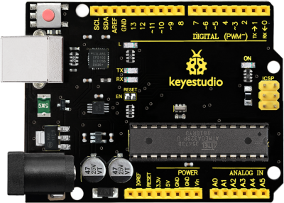
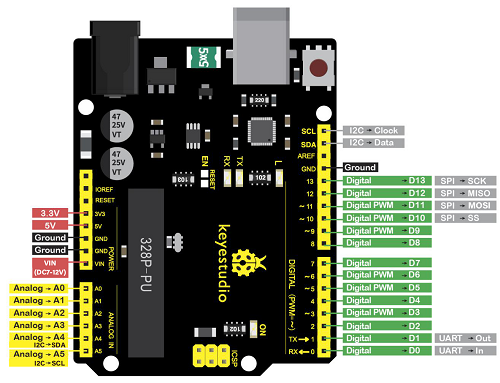
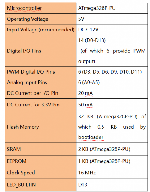
keyestudio V4.0 development board is an Arduino uno-compatible board, which is based on ATmega328P MCU, and with a cp2102 Chip as a UART-to-USB converter.
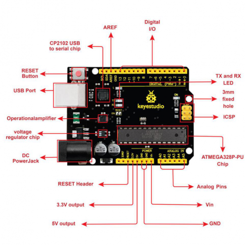
It has 14 digital input/output pins (of which 6 can be used as PWM outputs), 6 analog inputs, a 16 MHz quartz crystal, a USB connection, a power jack, 2 ICSP headers and a reset button.
It contains everything needed to support the microcontroller; simply connect it to a computer with a USB cable or power it via an external DC power jack (DC 7-12V) or via female headers Vin/ GND(DC 7-12V) to get started.
Keyestudio MEGA 2560 Board
Keyestudio Mega 2560 R3 is a microcontroller board based on the ATMEGA2560-16AU , fully compatible with ARDUINO MEGA 2560 R3.
It has 54 digital input/output pins (of which 15 can be used as PWM outputs), 16 analog inputs, 4 UARTs (hardware serial ports), a 16 MHz crystal oscillator, a USB connection, a power jack, 1 ICSP header, and a reset button. The built-in ICSP port can burn the firmware for ATMEGA2560-16AU directly. This chip is burnt the firmware well before leaving the factory, therefore, we hardly use it. We can power on by USB wire, DC head and Vin GND pins. To facilitate wiring, a 0.5 m USB wire is provided for you.
Specialized Functions of Some Pins:
1. Serial Communication: D0 (RX0) and D1 (TX1); Serial 1: D19 (RX1) and D18 (TX1); Serial 2: D17 (RX2) and D16 (TX2); Serial 3: D15 (RX3) and D14 (TX3). Used to receive (RX) and transmit (TX) TTL serial data. Pins 0 and 1 are also connected to the corresponding pins of the CP2102 USB-to-TTL Serial chip.
2. PWM Pins (Pulse-Width Modulation): D2 to D13, and D44 to D46. Provide 8-bit PWM output with the analogWrite() function.
3. External Interrupts: D2 (interrupt 0), D3 (interrupt 1), D18 (interrupt 5), D19 (interrupt 4), D20 (interrupt 3), and D21 (interrupt 2). These pins can be configured to trigger an interrupt on a low level, a rising or falling edge, or a change in level. See the attachInterrupt() function for details.
4. SPI communication: D53 (SS), D52 (SCK), D51 (MOSI), D50 (MISO). These pins support SPI communication using theSPI library. The SPI pins are also broken out on the ICSP header, which is physically compatible with the Arduino Uno.
5. IIC communication: D20 (SDA); D21 (SCL). Support TWI communication using the Wire library.
Installing driver
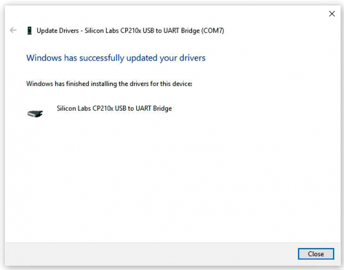
Let’s install the driver of keyestudio PLUS control board. The USB-TTL chip on PLUS board adopts CP2102 serial chip. The driver program of this chip is included in Arduino 1.8 version and above, which is convenient. Plug on USB port of board, the computer can recognize the hardware and automatically install the driver of CP2102.
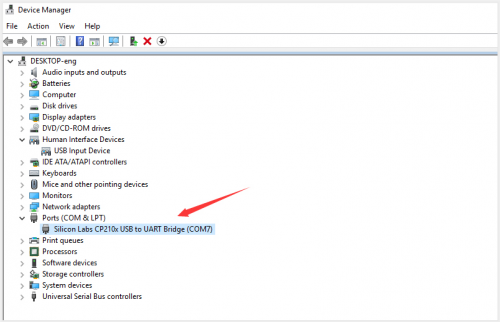
If install unsuccessfully, or you intend to install manually, open the device manager of computer. Right click Computer—— Properties—— Device Manager.
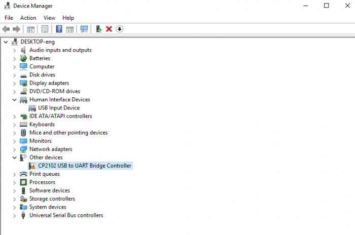
There is a yellow exclamation mark on the page, which implies installing the driver of CP2102 unsuccessfully. Then we double click the hardware and update the driver.
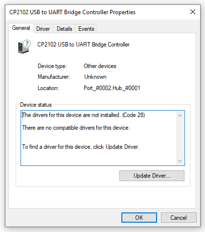
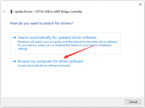
Click “OK” to enter the following page, click “browse my computer for updated driver software”, find out the installed or downloaded ARDUINO software. As shown below:
There is a DRIVERS folder in Arduino software installed package(![]() ), open driver folder and you can see the driver of CP210X series chips.
), open driver folder and you can see the driver of CP210X series chips.
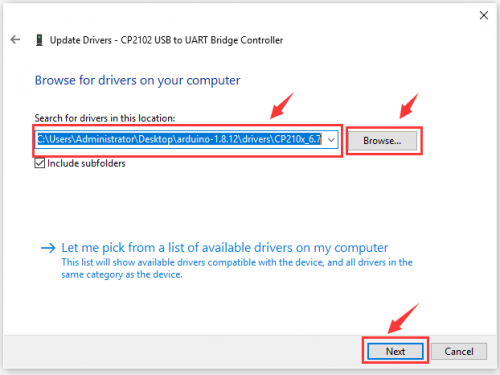
We click “Browse”, then find out the driver folder, or you could enter “driver” to search in rectangular box, then click “next”, the driver will be installed successfully. (I place Arduino software folder on the desktop, you could follow my way)
Open device manager, we will find the yellow exclamation mark disappear. The driver of CP2102 is installed successfully.
Arduino IDE Setting
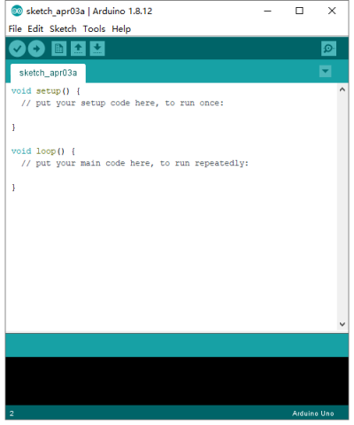
Click icon,open Arduino IDE.
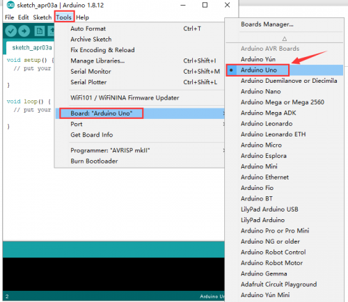
To avoid the errors when uploading the program to the board, you need to select the correct Arduino board that matches the board connected to your computer.
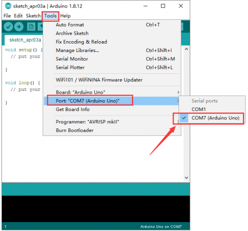
Then come back to the Arduino software, you should click Tools→Board, select the board. (as shown below)
Then select the correct COM port (you can see the corresponding COM port after the driver is successfully installed)
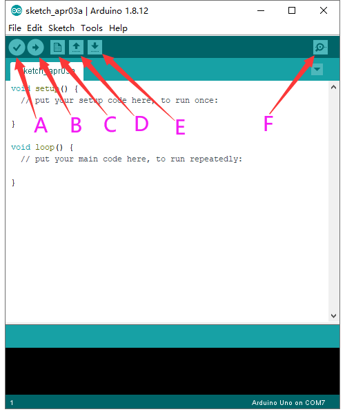
Before uploading the program to the board, let’s demonstrate the function of each symbol in the Arduino IDE toolbar.
A- Used to verify whether there is any compiling mistakes or not.
B- Used to upload the sketch to your Arduino board.
C- Used to create shortcut window of a new sketch.
D- Used to directly open an example sketch.
E- Used to save the sketch.
F- Used to send the serial data received from board to the serial monitor.
Start your first program
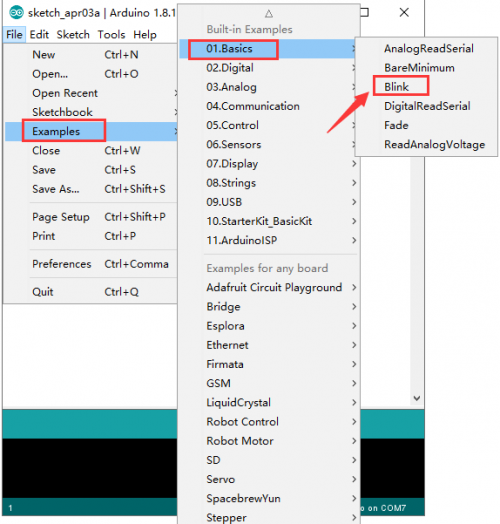
Open the file to select Example, choose BLINK from BASIC, as shown below:
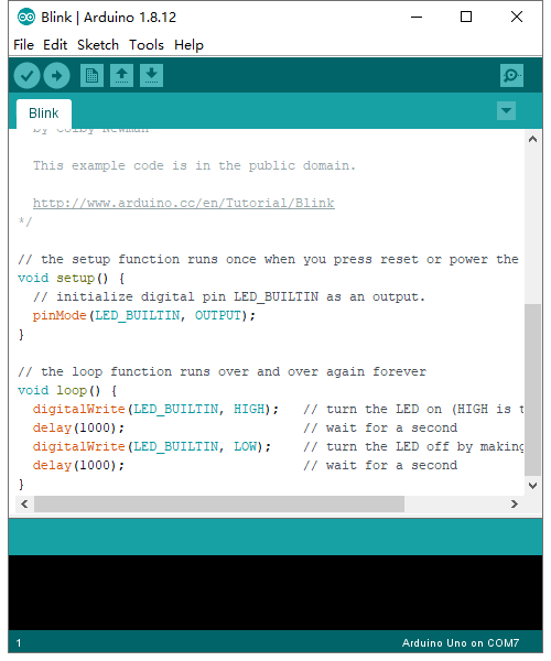
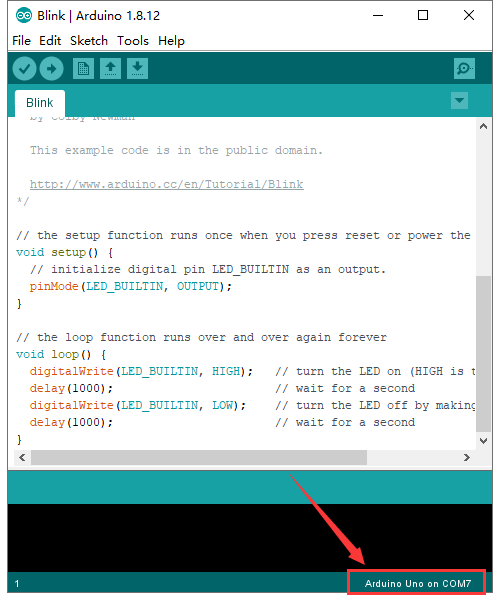
Set board and COM port, the corresponding board and COM port are shown on the lower right of IDE.
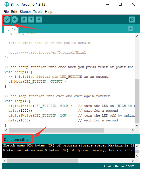
Click ![]() to start compiling the program, check errors.
to start compiling the program, check errors.
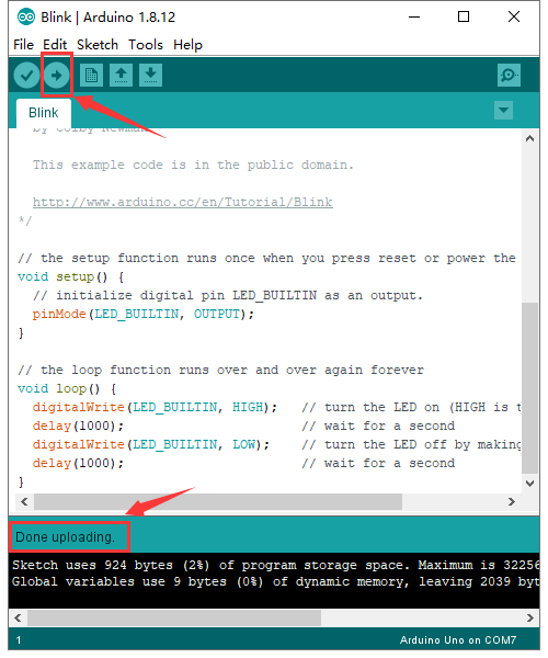
Click ![]() to upload the program, upload successfully.
to upload the program, upload successfully.
Upload the program successfully, the onboard LED lights on for 1s, lights off for 1s. Congratulation, you finish the first program.
Add Project Libraries
What are Libraries ?
Libraries are a collection of code that makes it easy for you to connect to a sensor,display, module, etc.
For example, the built-in LiquidCrystal library helps talk to LCD displays. There are hundreds of additional libraries available on the Internet for download.
The built-in libraries and some of these additional libraries are listed in the reference.
How to Install a Library ?
Here we will introduce the most simple way for you to add libraries.
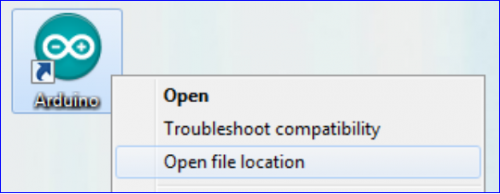
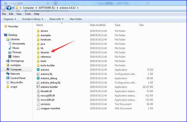
Step 1:After downloading well the Arduino IDE, you can right-click the icon of Arduino IDE.
Find the option «Open file location» shown as below:
Step 2: Enter it to find out libraries folder which is the library file of Arduino.
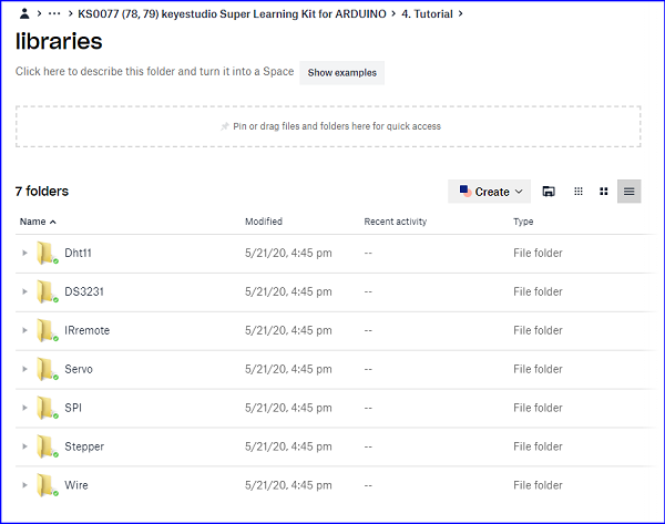
Step 3 Next to find out the “libraries” folder of this kit(seen in the link https://fs.keyestudio.com/KS0077-78-79)


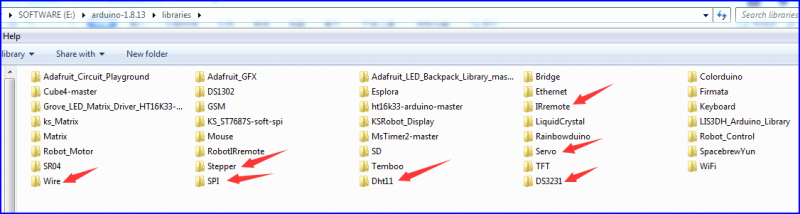
You just need to replicate and paste above libraries into the libraries folder of Arduino IDE.
Then the libraries of this kit are installed successfully, as shown below
Note the Arduino software download and the driver installation of keyetudio Mega 2560 R3 board is similar to arduino V4.0 board.
Project Details
Project 1: Hello World

1.Introduction
As for starters, we will begin with something simple. In this project, you only need an Arduino and a USB Cable to start the «Hello World!» experiment. It is not only a communication test of your Arduino and PC, but also a primer project for you to have your first try in the Arduino world!
2.Hardware Required
- V4.0 Board or MEGA 2650 Board*1
- USB cable*1
3.Sample Code
After installing driver for Arduino, let’s open Arduino software and compile code that enables Arduino to print «Hello World!» under your instruction. Of course, you can compile code for Arduino to continuously echo «Hello World!» without instruction.
A simple If () statement will do the instruction trick. when Arduino gets an instruction and then to print «Hello World!”.
/*
keyestudio super learning kit
Project 1
Hello World
http//www.keyestudio.com
- /
int val;//define variable val
void setup()
{
Serial.begin(9600);// set the baud rate at 9600 .
}
void loop()
{
 val=Serial.read();// read the instruction or character from PC to Arduino, and assign them to Val.
 if(val=='R')// determine if the instruction or character received is “R”.
 {  // if it’s “R”,
    Serial.println("Hello World!");// display“Hello World!”string.
 }}//
///////////////////////////////////////////////////////////////
4.Test Result
Click to open the serial monitor, input an “R”, PC will receive the information from Arduino Hello World!
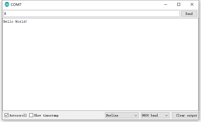
After choosing the proper port, the experiment is easy for you!
Project 2: LED Blinking
1.Introduction
Blinking LED experiment is quite simple. In the «Hello World!» program, we have come across LED. This time, we are going to connect an LED to one of the digital pins rather than using LED13 soldered to the board. Apart from an Arduino and a USB cable, you will need extra parts as below
2.Hardware Required
- V4.0 Board or MEGA 2650 Board*1
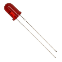
- Red M5 LED*1
- 220Ω Resistor*1
- Breadboard*1
- Breadboard Jumper Wire*2
- USB cable*1
3.Little Knowledge
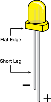
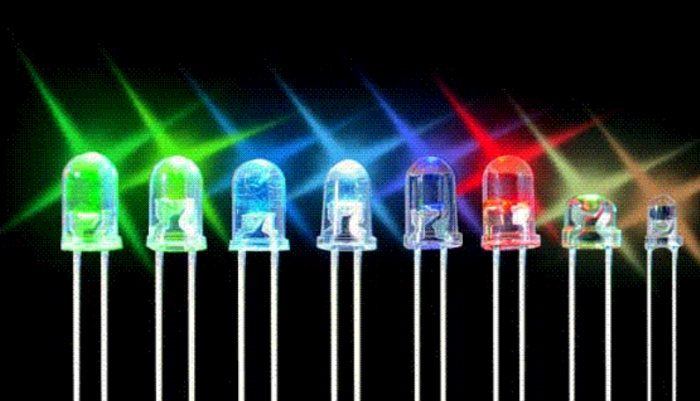
LED is a type of semiconductor called «Light Emitting Diode «which is an electronic device made of semiconductor materials (silicon, selenium, germanium, etc.). It is dubbed indicator, digital and word display in circuit and device. It has positive and negative poles. The short leg is negative pole, the long one is positive pole.
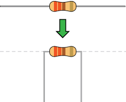
Resistor:Resistor is the electronic component in the circuit, which limits and regulates current flow. Its unit is (Ω).
The units larger than ohms are kiloohms (KΩ) and megaohms (MΩ). When in use, in addition to the size of the resistance, you must also pay attention to its power. In the project, the leads at both ends of the resistor should be bent at a 90° angle to fit the breadboard properly. If the lead is too long, it can be cut to an appropriate length.
A breadboard is used to build and test circuits quickly before finalizing any circuit design. The breadboard has many holes into which circuit components like ICs and resistors can be inserted. A typical breadboard is shown below:
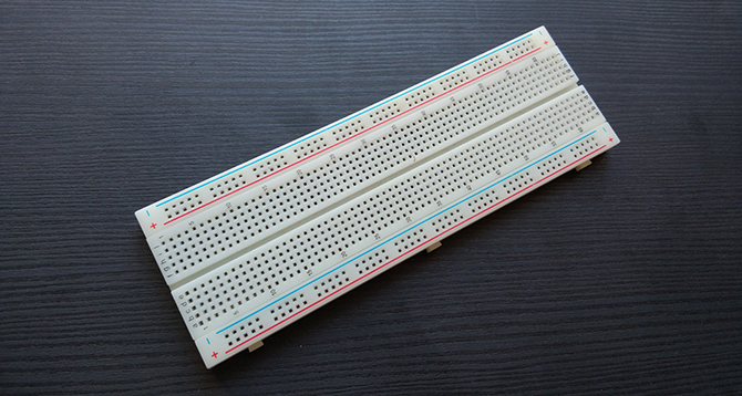
The bread board has strips of metal which run underneath the board and connect the holes on the top of the board. The metal strips are laid out as shown below. Note that the top and bottom rows of holes are connected horizontally while the remaining holes are connected vertically.
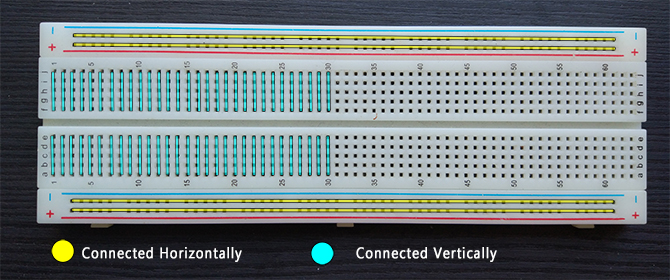
To use the bread board, the legs of components are placed in the holes. Each set of holes connected by a metal a strip underneath forms anode
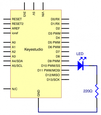
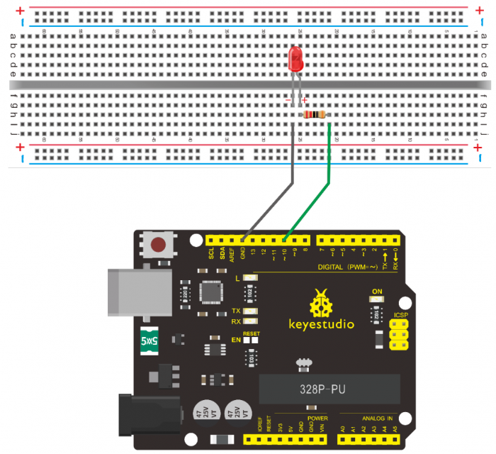
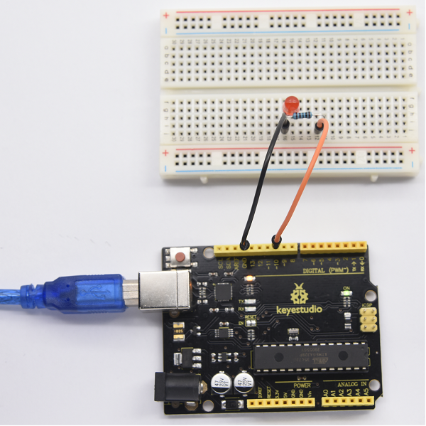
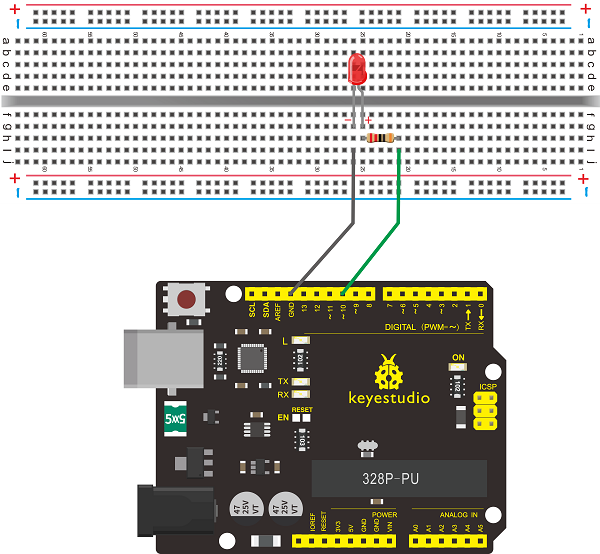
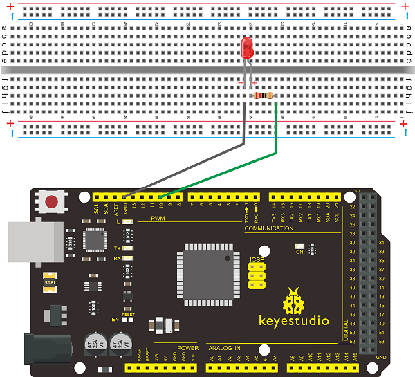
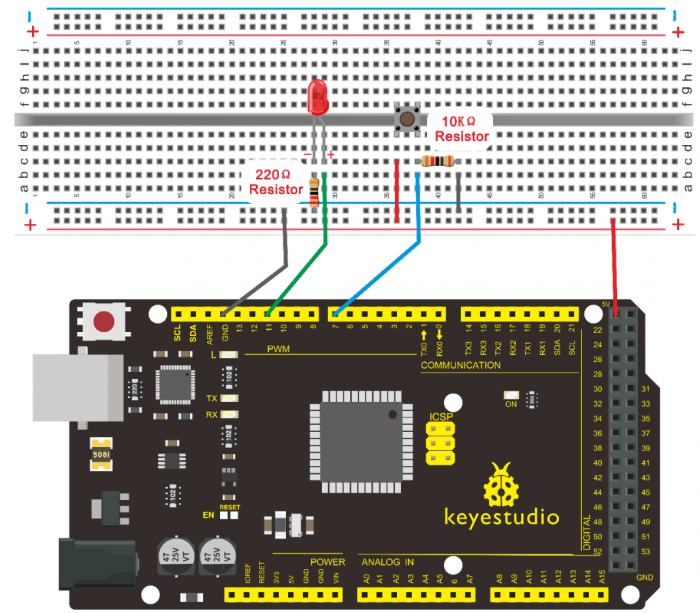
4.Circuit Connection
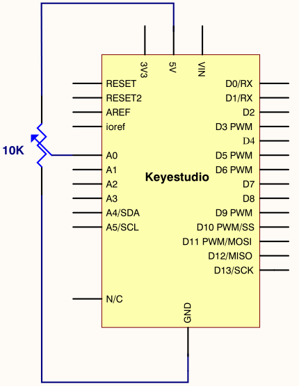
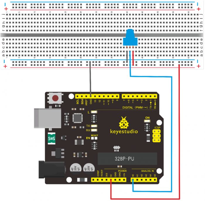
We follow below diagram from the experimental schematic link. Here we use digital pin 10. We connect LED to a 220 ohm resistor to avoid high current damaging the LED.
Connection for V4.0
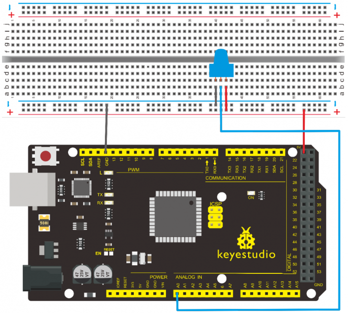
Connection for 2560

5.Sample Code
/*
keyestudio super learning kit
Project 2
Blink
http//www.keyestudio.com
- /
int ledPin = 10; // define digital pin 10.
void setup()
{
pinMode(ledPin, OUTPUT);// define pin with LED connected as output.
}
void loop()
{
digitalWrite(ledPin, HIGH); // set the LED on.
delay(1000); // wait for a second.
digitalWrite(ledPin, LOW); // set the LED off.
delay(1000); // wait for a second
}
//////////////////////////////////////////////////////////////////
6.Test Result
After uploading this program, in the experiment, you will see the LED connected to pin 10 turning on and off, with an interval of approximate one second.
In this way, blinking LED experiment is now completed. Thank you!
Project 3: PWM
1.Introduction
PWM, short for Pulse Width Modulation, is a technique used to encode analog signal level into digital ones. A computer cannot output analog voltage but only digital voltage values such as 0V or 5V. So we use a high resolution counter to encode a specific analog signal level by modulating the duty cycle of PMW.
2.Working Principle
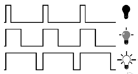
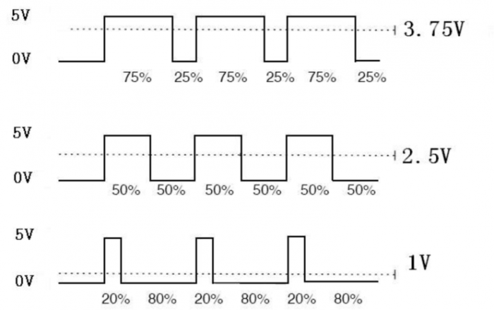
The PWM signal is also digitalized because in any given moment, fully on DC power supply is either 5V (ON), or 0V (OFF). The voltage or current is fed to the analog load (the device that uses the power) by repeated pulse sequence being ON or OFF. Being on, the current is fed to the load; being off, it’s not. With adequate bandwidth, any analog value can be encoded using PWM. The output voltage value is calculated via the on and off time.
Output voltage = (turn on time/pulse time) * maximum voltage value.
PWM has many applications lamp brightness regulating, motor speed regulating, sound making, etc.
The following are the three basic parameters of PMW.
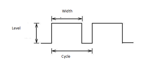
- 1.The amplitude of pulse width (minimum / maximum)
- 2. The pulse period (The reciprocal of pulse frequency in one second)
- 3. The voltage level(such as 0V-5V)
- There are 6 PMW interfaces on Arduino, namely digital pin 3, 5, 6, 9, 10, and 11.
- In previous experiments, we have done «button-controlled LED», using digital signal to control digital pin, also one about potentiometer.
- This time, we will use a potentiometer to control the brightness of the LED.
3.Hardware Required
- V4.0 Board or MEGA 2650 Board*1
- Red M5 LED*1
- 220Ω Resistor
- Breadboard*1
- Breadboard Jumper Wire*6
- USB cable*1
4.Circuit Connection
Connection for V4.0
Connection for 2560 R3
5.Sample Code
/*
keyestudio super learning kit
Project 3
pwm
http//www.keyestudio.com
*/
int ledPin = 10;
 void setup() {
     pinMode(ledPin,OUTPUT);
}
void loop(){
  for (int value = 0 ; value < 255; value=value+1){
    analogWrite(ledPin, value);
    delay(5);
  }
  for (int value = 255; value >0; value=value-1){
    analogWrite(ledPin, value);
    delay(5);
  }
}
//////////////////////////////////////////////////////////////////
6.Test Result
Hook up via connection diagram, upload the code and plug in power. The external LED lights up then gets dark gradually, which looks like human breath.
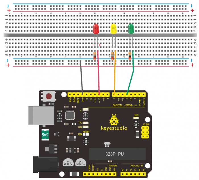
Project 4: Traffic Light
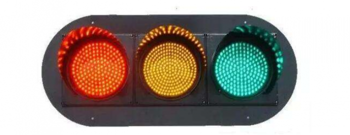
1.Introduction
In the previous program, we have done the LED blinking experiment with one LED. Now, it’s time to up the stakes to do a bit more complicated experiment-traffic light. Actually, these two experiments are similar. While in this traffic light experiment, we use three LEDs with different colors rather than an LED.
2.Hardware Required
- V4.0 Board or MEGA 2650 Board*1
- USB Cable *1
- Red M5 LED*1
- Yellow M5 LED*1
- Blue M5 LED*1
- 220Ω Resistor *3
- Breadboard*1
- Breadboard Jumper Wire *4
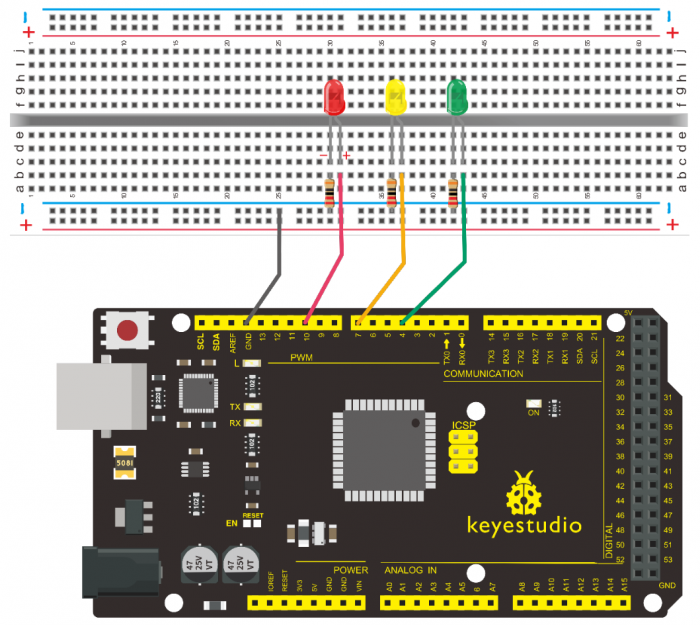
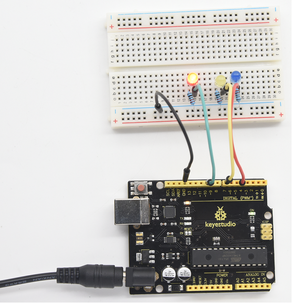
3.Circuit Connection
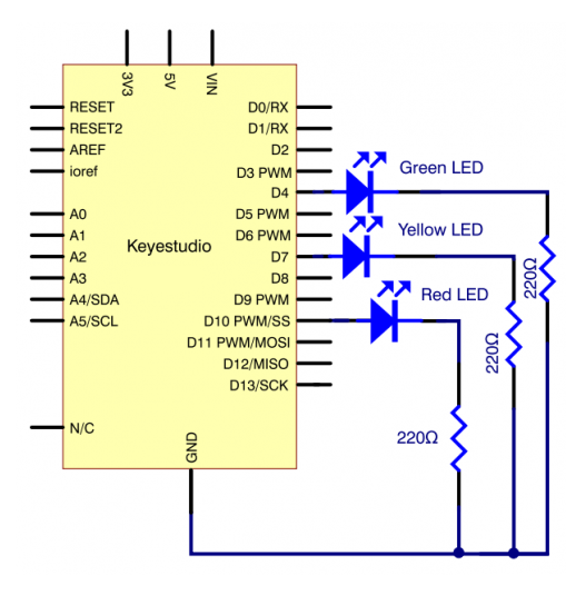
Connection for V4.0
Connection for 2560
4.Sample Code
Since it is a simulation of traffic lights, the blinking time of each LED should be the same with those in traffic lights system.
In this program, we use Arduino delay () function to control delay time, which is much simpler than C language.
/*
 keyestudio super learning kit
 Project 4
 traffic light
 http//www.keyestudio.com
*/
int redled =10; // initialize digital pin 10.
int yellowled =7; // initialize digital pin 7.
int blueled =4; // initialize digital pin 4.
void setup()
{
pinMode(redled, OUTPUT);// set the pin with red LED as “output”
pinMode(yellowled, OUTPUT); // set the pin with yellow LED as “output”
pinMode(blueled, OUTPUT); // set the pin with blue LED as “output”
}
void loop()
{
digitalWrite(blueled, HIGH);//// turn on blue LED
delay(5000);// wait 5 seconds
digitalWrite(blueled, LOW); // turn off blue LED
for(int i=0;i<3;i++)// blinks for 3 times
{
delay(500);// wait 0.5 second
digitalWrite(yellowled, HIGH);// turn on yellow LED
delay(500);// wait 0.5 second
digitalWrite(yellowled, LOW);// turn off yellow LED
}
delay(500);// wait 0.5 second
digitalWrite(redled, HIGH);// turn on red LED
delay(5000);// wait 5 second
digitalWrite(redled, LOW);// turn off red LED
}
//////////////////////////////////////////////////////////////////
5.Test Result
When the uploading process is completed, you can see traffic lights of your own design. Note this circuit design is very similar with the one in LED chasing effect.
The blue light will be on for 5 seconds, and then off, followed by the yellow light blinking for 3 times, and then the red light is on for 5 seconds, repeatedly forming a cycle.
Experiment is now completed, thank you!
Project 5: LED Chasing Effect
1.Introduction
We can see many billboards composed of colorful LEDs. They are constantly changing to form various effects. In this experiment, we compile a program to simulate chase effect.
2.Hardware Required
- V4.0 Board or MEGA 2650 Board*1
- Red LED*6
- 220Ω Resistor *6
- Breadboard Jumper Wire*12
- USB cable*1
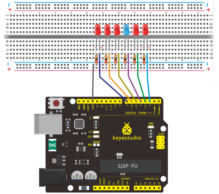
3.Circuit Connection
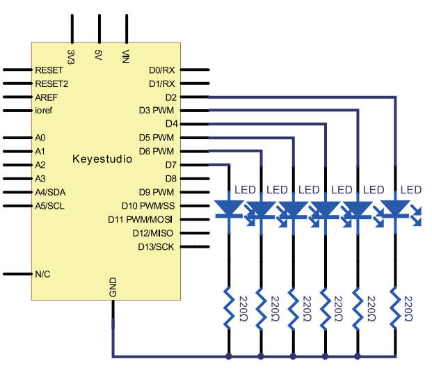
Connection for V4.0
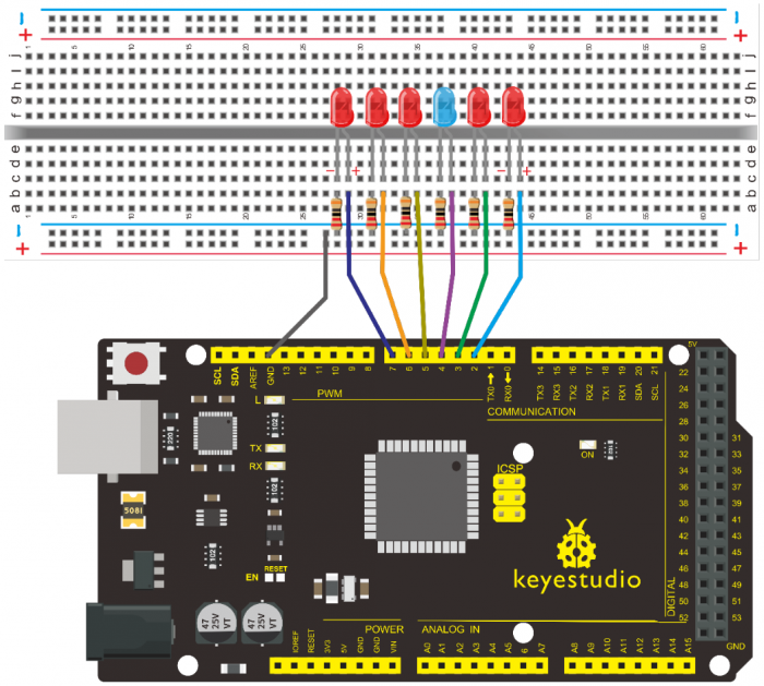
Connection for 2560
4.Sample Code
/*
 keyestudio super learning kit
 Project 5
 LED Chasing Effect
 http//www.keyestudio.com
*/
int BASE = 2 ;  // the I/O pin for the first LED
int NUM = 6;   // number of LEDs
void setup()
{
   for (int i = BASE; i < BASE + NUM; i ++)
   {
     pinMode(i, OUTPUT);   // set I/O pins as output
   }
}
void loop()
{
   for (int i = BASE; i < BASE + NUM; i ++)
   {
     digitalWrite(i, LOW);    // set I/O pins as “low”, turn off LEDs one by one.
     delay(200);        // delay
   }
   for (int i = BASE; i < BASE + NUM; i ++)
   {
     digitalWrite(i, HIGH);    // set I/O pins as “high”, turn on LEDs one by one
     delay(200);        // delay
   }
}
//////////////////////////////////////////////////////////////////
5.Test Result
You can see the LEDs blink by sequence.
Project 6: Button-Controlled LED
1.Introduction
I/O port means interface for INPUT and OUTPUT. Up to now, we have only used the OUTPUT function.
In this experiment, we will try to use the INPUT function, which is to read the output value of device connecting to it.
We use 1 button and 1 LED using both input and output to give you a better understanding of the I/O function.
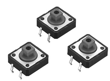
Button switch, familiar to most of us, is a switch value (digital value) component. When it’s pressed, the circuit is in closed (conducting) state.
2.Hardware Required
- V4.0 Board or MEGA 2650 Board*1
- Button switch*1
- Red M5 LED*1
- 220ΩResistor*1
- 10KΩ Resistor*1
- Breadboard*1
- Breadboard Jumper Wire*6
- USB cable*1
3. Little Knowledge
I believe that button switch is common and popular for people. It belongs to switch quantity( digital quantity)component. Composed of normally open contact and normally closed contact,its working principle is similar with ordinary switch.
When the normally open contact bears pressure, the circuit is on state ; however, when this pressure disappears, the normally open contact goes back to initial state, that is, off state. The pressure is the act we switch the button.
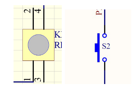
Schematic Diagrams:
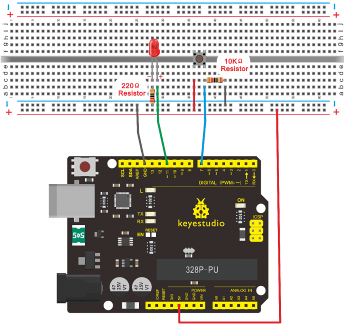
4. Circuit Connection
Connection for V4.0
Connection for 2560
5.Sample Code
Now, let’s begin the compiling. When the button is pressed, the LED will be on. Based on the previous study, the coding should be easy for you.
In this program, we add a statement of judgment. Here, we use an if () statement.
Arduino IDE is based on C language, so statements of C language such as while, switch etc. can certainly be used for Arduino program.
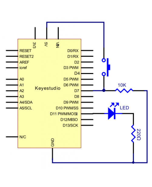
When we press the button, pin 7 will output high level. We can program pin 11 to output high level and turn on the LED. When pin 7 outputs low level, pin 11 also outputs low level and the LED remains off.
/*
 keyestudio super learning kit
 Project 6
 Button
 http//www.keyestudio.com
*/
int ledpin=11;// initialize pin 11
int inpin=7;// initialize pin 7
int val;// define val
void setup()
{
pinMode(ledpin,OUTPUT);// set LED pin as “output”
pinMode(inpin,INPUT);// set button pin as “input”
}
void loop()
{
val=digitalRead(inpin);// read the level value of pin 7 and assign if to val
if(val==LOW)// check if the button is pressed, if yes, turn on the LED
{ digitalWrite(ledpin,LOW);}
else
{ digitalWrite(ledpin,HIGH);}
}
//////////////////////////////////////////////////////////////////
6.Test Result
When the button is pressed, LED is on, otherwise, LED remains off. In this way, the button controlled LED experiment is completed.
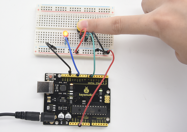
The simple principle of this experiment is widely used in a variety of circuit and electric appliances. You can easily come across it in your daily life. One typical example is when you press a certain key on your phone, the backlight will be on.
Project 7: Active Buzzer
1.Introduction
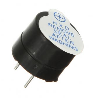
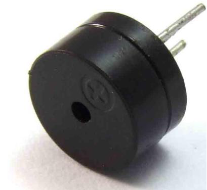
Active buzzer is widely used as a sound making element on computer, printer, alarm, electronic toy, telephone, timer and more. It has an inner vibration source. Simply connect it with 5V power supply, it can buzz continuously.
2.Hardware Required
- V4.0 Board or MEGA 2650 Board*1
- Buzzer*1
- Breadboard*1
- Breadboard Jumper Wire*2
- USB cable*1
3. Little Knowledge
There are two kinds of buzzer, active buzzer and passive buzzer. In this lesson, we will use Micro:bit to drive an active buzzer. The active buzzer inside has a simple oscillator circuit which can convert constant direct current into a certain frequency pulse signal. Once active buzzer receives a high level, it will produce an audible beep.
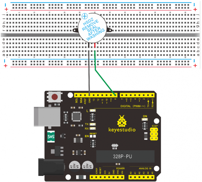
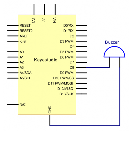
4.Circuit Connection
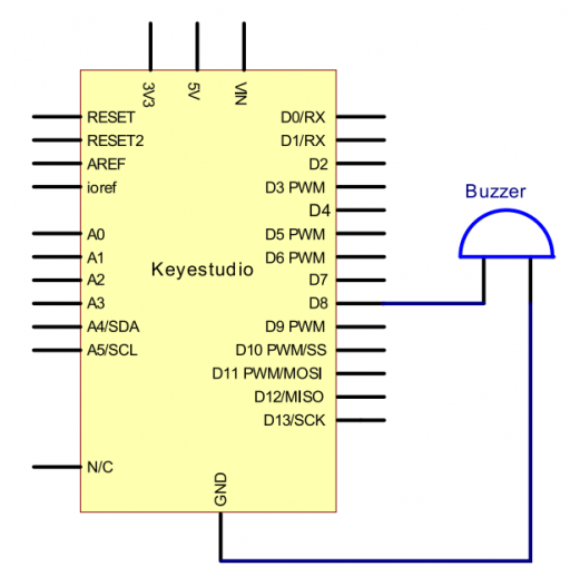
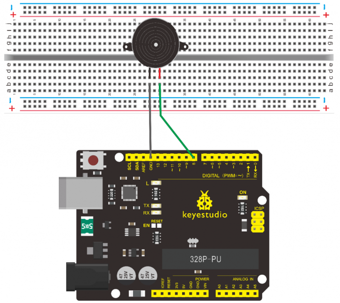
Connection for V4.0
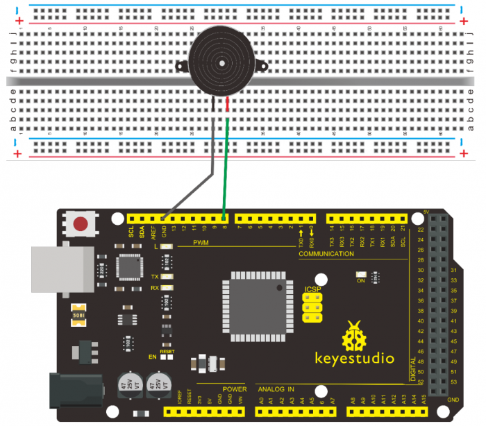
Connection for 2560
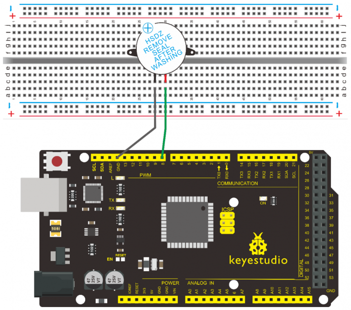
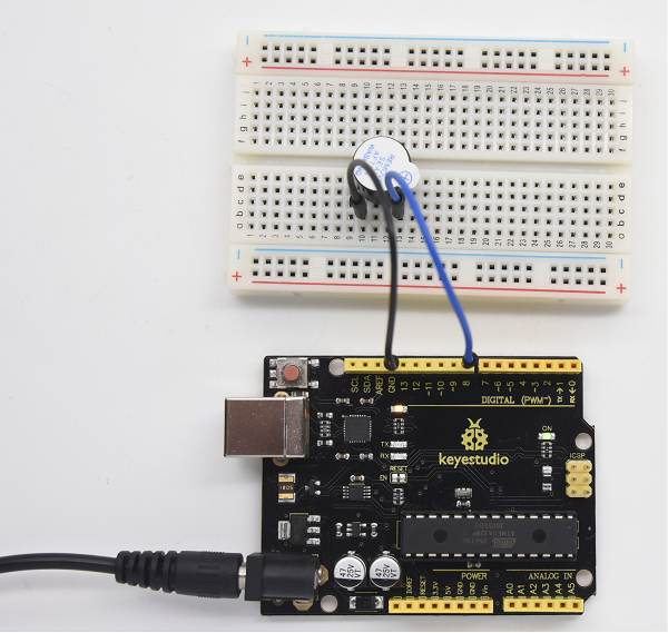
When connecting the circuit, pay attention to the positive and negative poles of the buzzer. In the photo, you can see there are red and black lines. When the circuit is finished, you can begin the programming.
5.Sample Code
Program is simple. You control the buzzer by outputting high/low level.
/*
 keyestudio super learning kit
 Project 7
 Active Buzzer
 http//www.keyestudio.com
*/
int buzzer=8;// initialize digital IO pin that controls the buzzer
void setup()
{
  pinMode(buzzer,OUTPUT);// set pin mode as “output”
}
void loop()
{
digitalWrite(buzzer, HIGH); // produce sound
}
//////////////////////////////////////////////////////////////////
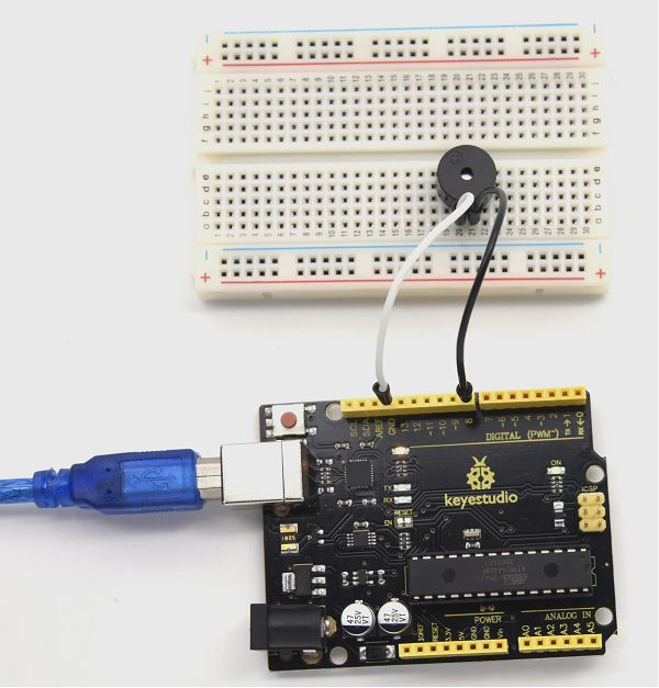
6.Test Result
After uploading the program, the buzzer experiment is completed. You can see the buzzer is ringing.
Project 8: Passive Buzzer
1.Introduction
We can use Arduino to make many interactive works. The most commonly used one is acoustic-optic display. All the previous experiment has something to do with LED. However, the circuit in this experiment can produce sound. Normally, the experiment is done with a buzzer but not a speaker while buzzer is more simpler and easier to use.
The buzzer we introduced here is a passive buzzer. It cannot be actuated by itself, but by external pulse frequencies. Different frequency produces different sound. We can use Arduino to code the melody of a song, which is quite fun and simple.
2.Hardware Required
- V4.0 Board or MEGA 2650 Board*1
- Passive Buzzer*1
- Breadboard*1
- Breadboard Jumper Wire*2
- USB cable*1
3. Little knowledge
Passive buzzer is an integrated electronic buzzer without vibration source inside. It must be driven by 2K-5K square wave instead of direct current signals. There is little difference between the two buzzers, but when the pins of the two buzzers are placed up, the passive buzzer comes with green circuit board, and the one sealed with vinyl is an active buzzer.
4.Circuit Connection
Connection for V4.0
Connection for 2560
5.Sample Code
/*
keyestudio super learning kit
Project 8
Passive Buzzer
http//www.keyestudio.com
*/
int buzzer=8;// select digital IO pin for the buzzer
void setup()
{
pinMode(buzzer,OUTPUT);// set digital IO pin pattern, OUTPUT to be output
}
void loop()
{ unsigned char i,j;//define variable
while(1)
{ for(i=0;i<80;i++)// output a frequency sound
{ digitalWrite(buzzer,HIGH);// sound
delay(1);//delay1ms
digitalWrite(buzzer,LOW);//not sound
delay(1);//ms delay
}
for(i=0;i<100;i++)// output a frequency sound
{ digitalWrite(buzzer,HIGH);// sound
delay(2);//2ms delay
digitalWrite(buzzer,LOW);//not sound
delay(2);//2ms delay
}}}
//////////////////////////////////////////////////////////////////
6.Test Result
After uploading the program, buzzer experiment is finished, you can hear the buzzer sound.
Project 9: RGB LED
1.Introduction
The RGB color mode is a color standard in the industry. It obtains various colors by changing the three color channels of red (R), green (G), and blue (B) and integrating them. RGB denotes the three colors of red, green and blue.
In this project, we use Arduino to mix these three colors in equal amounts to produce white light.
2.Hardware Required
- V4.0 Board or MEGA 2650 Board*1
- USB Cable * 1
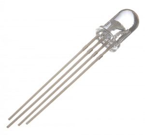
- RGB LED * 1
- Resistor *3
- Breadboard jumper wire*5
3. Little Knowledge
The monitors mostly adopt the RGB color standard, and all the colors on the computer screen are composed of the three colors of red, green and blue mixed in different proportions.
RGB is inclusive of common cathode RGB and common anode RGB.
And we could adjust the LED brightness by PWM
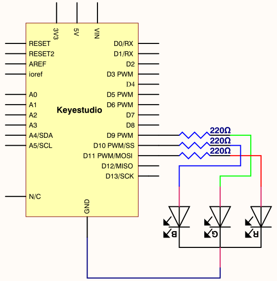
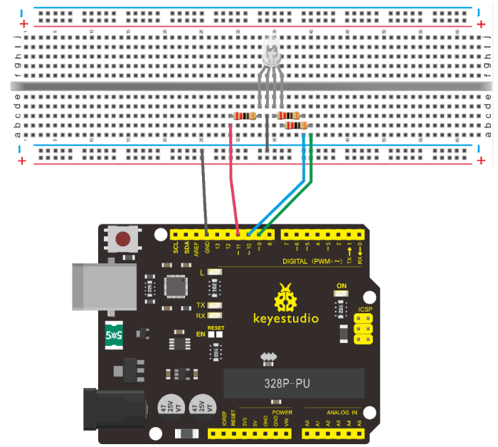
4.Circuit Connection
Connection for V4.0
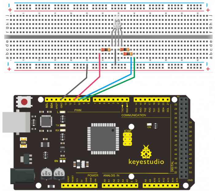
Connection for 2560
5.Sample Code
/*
 keyestudio super learning kit
 Project 9
 RGB
 http//www.keyestudio.com
*/
int redpin = 11; //select the pin for the red LED
int bluepin =10; // select the pin for the blue LED
int greenpin =9;// select the pin for the green LED
int val;
void setup() {
  pinMode(redpin, OUTPUT);
  pinMode(bluepin, OUTPUT);
  pinMode(greenpin, OUTPUT);
  Serial.begin(9600);
}
void loop()
{
for(val=255; val>0; val--)
  {
   analogWrite(11, val);
   analogWrite(10, 255-val);
   analogWrite(9, 128-val);
   delay(1);
  }
for(val=0; val<255; val++)
  {
   analogWrite(11, val);
   analogWrite(10, 255-val);
   analogWrite(9, 128-val);
   delay(1);
  }
 Serial.println(val, DEC);
}
//////////////////////////////////////////////////////////////////
6.Test Result
Directly copy the above code into arduino IDE, and click upload, wait for a few seconds, you can see a full-color LED.
Project 10: Photo Resistor
1.Introduction
After completing all the previous experiments, you may acquire some basic understanding and knowledge about Arduino application. We have introduced digital input and output, analog input and PWM.
Now, let’s begin the learning of sensor applications.
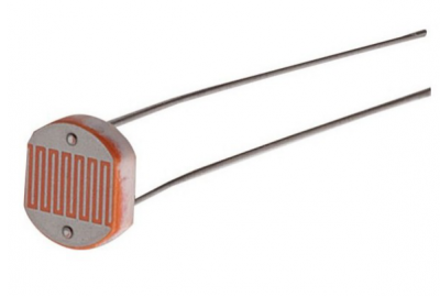
Photo Resistor (Photovaristor) is a resistor whose resistance varies from different incident light strength. It’s based on the photoelectric effect of semiconductor. If the incident light is intense, its resistance reduces; if the incident light is weak, the resistance increases.
2.Hardware Required
- V4.0 Board or MEGA 2650 Board*1
- Photo Resistor*1
- Red M5 LED*1
- 10KΩ Resistor*1
- 220Ω Resistor*1
- Breadboard*1
- Breadboard Jumper Wire*5
- USB cable*1
3.Little Knowledge
Photovaristor is commonly applied in the measurement of light, light control and photovoltaic conversion (convert the change of light into the change of electricity).
Photo resistor is also being widely applied to various light control circuit, such as light control and adjustment, optical switches, etc.
We will start with a relatively simple experiment regarding to photovaristor application.
Photovaristor is an element that can change its resistance as light strength changes. So need to read the analog value. You can refer to the PWM experiment, replacing the potentiometer with photovaristor. When there is change in light strength, it will make corresponding change on the LED.
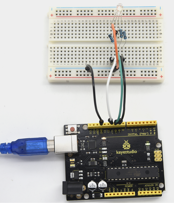
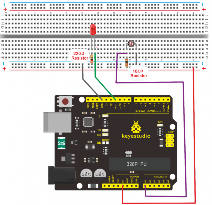
4.Circuit Connection
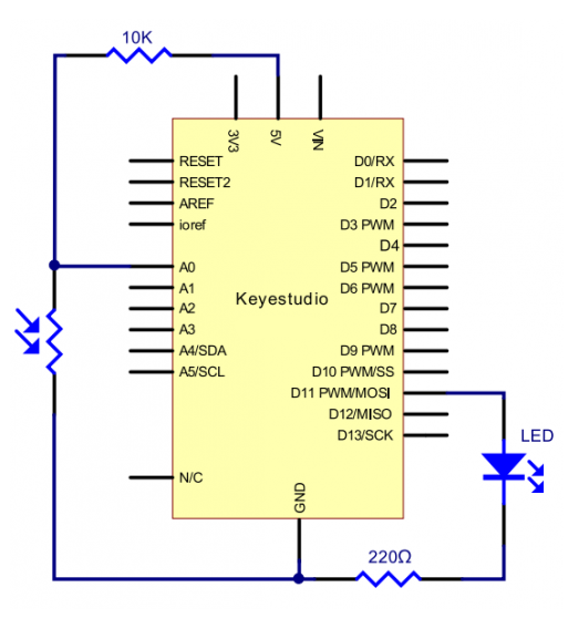
Connection for V4.0
Connection for 2560
5.Sample Code
After wiring, let’s begin the program compiling. The program is similar to the PWM.
For change detail, please refer to the Sample Code below.
/*
 keyestudio super learning kit
 Project 10
 Photo Resistor
 http//www.keyestudio.com
*/
int potpin=0;// initialize analog pin 0, connected with photovaristor
int ledpin=11;// initialize digital pin 11,
int val=0;// initialize variable va
void setup()
{
pinMode(ledpin,OUTPUT);// set digital pin 11 as “output”
Serial.begin(9600);// set baud rate at “9600”
}
void loop()
{
val=analogRead(potpin);// read the value of the sensor and assign it to val
Serial.println(val);// display the value of val
analogWrite(ledpin,val/4);// set up brightness(maximum value 255)
delay(10);// wait for 0.01
}
//////////////////////////////////////////////////////////////////
6.Test Result
After downloading the program, you can change the light strength around the photovaristor, and see the corresponding brightness change of the LED.
Photovaristors has various applications in our everyday. You can make other interesting interactive projects based on this one.
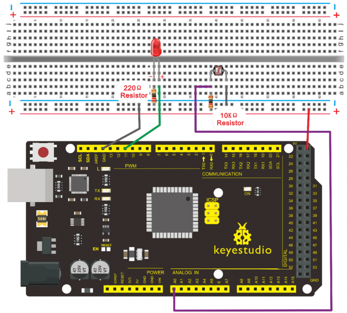
Project 11: Flame Sensor
1.Introduction
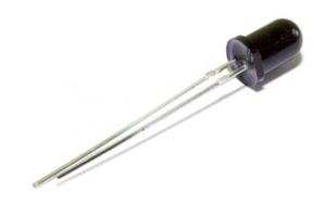
Flame sensor (infrared receiving triode) is specially used for robots to find the fire source. This sensor is of high sensitivity to flame.
2.Hardware Required
- V4.0 Board or MEGA 2650 Board*1
- Flame Sensor *1
- Buzzer *1
- 10K Resistor *1
- Breadboard Jumper Wire*6
- USB cable*1
3. Little Knowledge
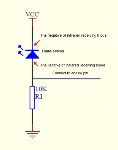
Flame sensor is based on the principle that infrared ray is highly sensitive to flame. It has an infrared receiving tube specially designed to detect fire, and then to convert the flame brightness into fluctuating level signal. The signals are then input into the central processor and be dealt with accordingly.
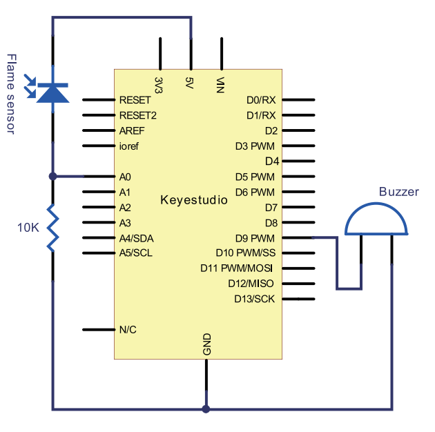
The shorter lead of the receiving triode is for negative, the other one for positive. Connect negative to 5V pin, positive to resistor; connect the other end of the resistor to GND, connect one end of a jumper wire to a clip which is electrically connected to sensor positive, the other end to analog pin. As shown below
4.Experiment Principle
When it’s approaching a fire, the voltage value read from the analog port will differ. If you use a multimeter, you can see that when there is no fire approaching, the voltage it reads is around 0.3V; when there is fire approaching, the voltage it reads is around 1.0V. The nearer the fire is, the higher the voltage is.
So in the beginning of the program, you can initialize voltage value i (no fire value); Then, continuously read the analog voltage value j and obtain difference value k=j-i; compare k with 0.6V (123 in binary) to determine whether there is a fire approaching or not; if yes, the buzzer will buzz.
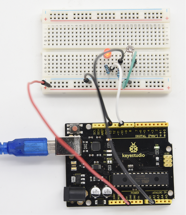
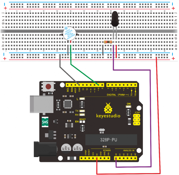
5.Circuit Connection
Connection for V4.0
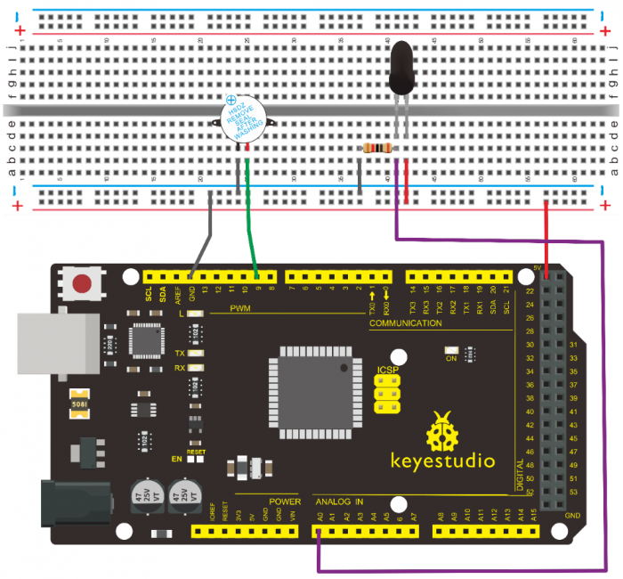
Connection for MEGA 2560
6.Sample Code
/*
keyestudio super learning kit
Project 11
Flame
http//www.keyestudio.com
*/
int flame=0;// select analog pin 0 for the sensor
int Beep=9;// select digital pin 9 for the buzzer
int val=0;// initialize variable
 void setup()
{
  pinMode(Beep,OUTPUT);// set LED pin as “output”
 pinMode(flame,INPUT);// set buzzer pin as “input”
 Serial.begin(9600);// set baud rate at “9600”
 }
void loop()
{
  val=analogRead(flame);// read the analog value of the sensor
  Serial.println(val);// output and display the analog value
  if(val>=600)// when the analog value is larger than 600, the buzzer will buzz
  {
   digitalWrite(Beep,HIGH);
   }else
   {
     digitalWrite(Beep,LOW);
    }
   delay(500);
}
//////////////////////////////////////////////////////////////////
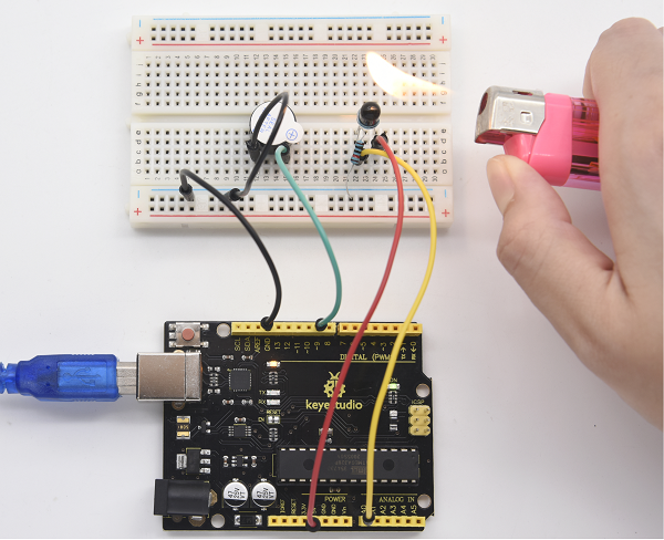
7.Test Result
This program can simulate an alarm when there is a fire. Everything is normal when there is no fire; when there is fire, the alarm will be set off immediately.
Project 12: LM35 Temperature Sensor
1.Introduction
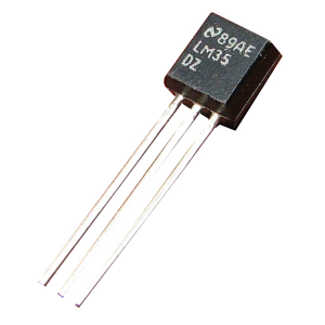
LM35 is a common and easy-to-use temperature sensor. It does not require other hardware. You just need an analog port to make it work. The difficulty lies in compiling the code to convert the analog value it reads into Celsius temperature. In this project, we will guide you how to use LM35 temperature sensor.
2. Working Principle
LM35 is a widely used temperature sensor with many different package types. At room temperature, it can achieve the accuracy of ±1/4°C without additional calibration processing.
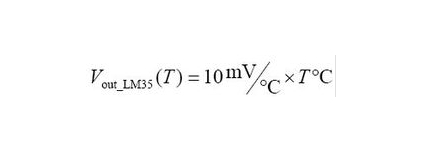
LM35 temperature sensor can produce different voltage by different temperature
When temperature is 0 ℃, it outputs 0V; if increasing 1 ℃, the output voltage will increase 10 mv.
The output temperature is 0℃~100℃, the conversion formula is as follows:
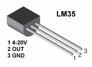
3.Hardware Required
- V4.0 Board or MEGA 2650 Board*1
- LM35*1
- Breadboard*1
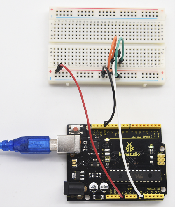
- Breadboard Jumper Wire*5
- USB cable*
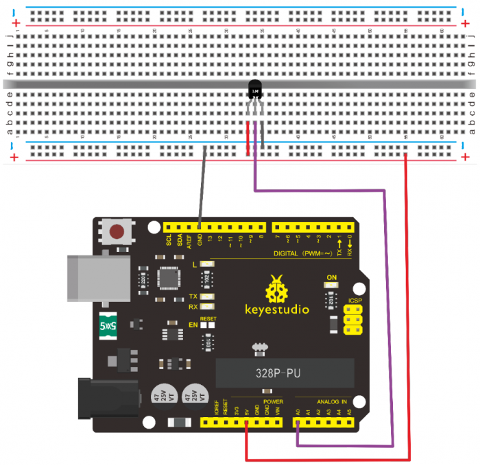
4.Circuit Connection
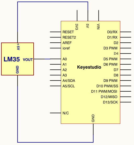
Connection for V4.0
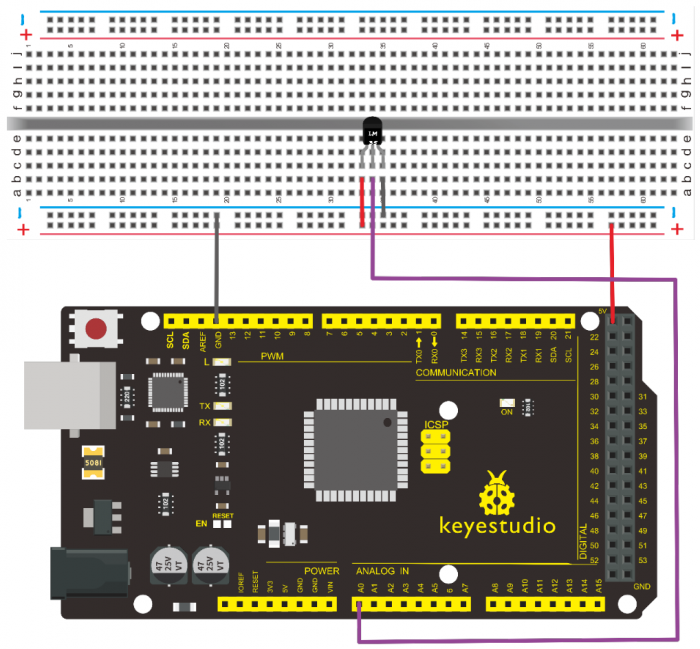
Connection for 2560
5.Sample Code
/*
 keyestudio super learning kit
 Project 12
 LM35
 http//www.keyestudio.com
*/
int potPin = 0; // initialize analog pin 0 for LM35 temperature sensor
void setup()
{
Serial.begin(9600);// set baud rate at”9600”
}
void loop()
{
int val;// define variable
int dat;// define variable
val=analogRead(0);// read the analog value of the sensor and assign it to val
dat=(125*val)>>8;// temperature calculation formula
Serial.print("Tep");// output and display characters beginning with Tep
Serial.print(dat);// output and display value of dat
Serial.println("C");// display “C” characters
delay(500);// wait for 0.5 second
}
//////////////////////////////////////////////////////////////////
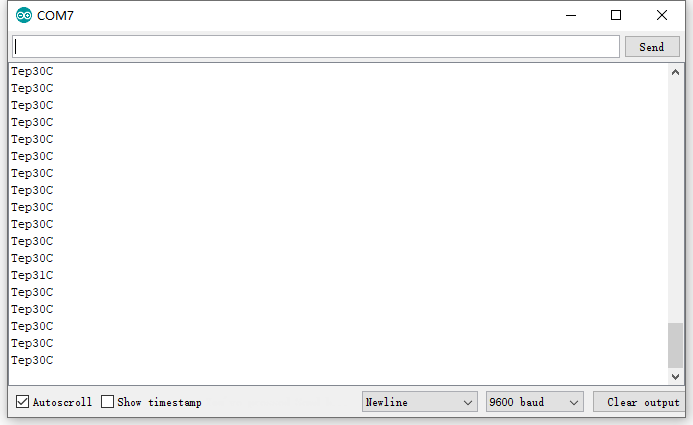
6.Test Result
After uploading the program, you can open the monitoring window to see the current temperature.
Project 13: Tilt Switch
1.Introduction
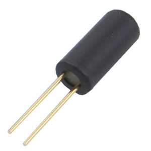
This is a ball switch experiment . The ball switch is also dubbed a steel ball switch. It controls the circuit by connecting guide pin with rolling ball. In this project, we control the LED light by reading the state of the ball switch.
2.Working Principle
When one end of the switch is below horizontal position, the switch is on. The voltage of the analog port is about 5V (1023 in binary). The LED will be on.
When the other end of the switch is below horizontal position, the switch is off. The voltage of the analog port is about 0V (0 in binary). The LED will be off.
In the program, we determine whether the switch is on or off according to the voltage value of the analog port, whether it’s above 2.5V (512 in binary) or not.
3.Hardware Required
- V4.0 Board or MEGA 2650 Board*1
- Ball switch*1
- Led *1
- 220Ω Resistor*1
- 10KΩ resistor*1
- Breadboard Jumper Wire*5
- USB cable*1
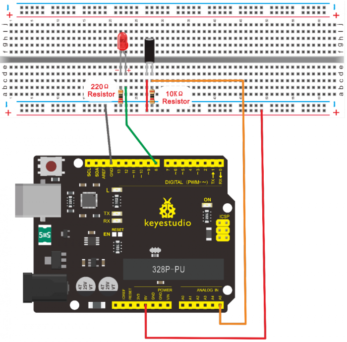
4.Circuit Connection
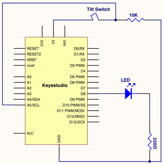
Connection for V4.0
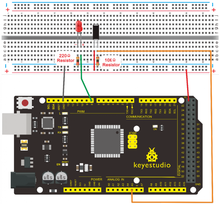
Connection for 2560
5.Sample Code
/*
 keyestudio super learning kit
 Project 13
 Tilt Switch
 http//www.keyestudio.com
*/
void setup()
{
  pinMode(8,OUTPUT);// set digital pin 8 as “output”
}
void loop()
{
int i;// define variable i
while(1)
{
  i=analogRead(5);// read the voltage value of analog pin 5
  if(i>512)// if larger that 512(2.5V)
  {
    digitalWrite(8,LOW);// turn on LED
  }
  else// otherwise
  {
    digitalWrite(8,HIGH);// turn off LED
  } } }
//////////////////////////////////////////////////////////////////
6.Test Result
Hold the breadboard with your hand. Tilt it to a certain extent, the LED will be on. If there is no tilt, the LED will be off.
The principle of this experiment can be also applied to relay control.
Experiment now is completed. Thank you!
Project 14: IR Remote Control
1.Introduction
What is an infrared receiver?
The signal from the infrared remote controller is a series of binary pulse code. To avoid the other infrared signal interference during the wireless transmission, the signal is pre-modulated at a specific carrier frequency and then send out by an infrared emission diode.
The infrared receiving device needs to filter out other waves and receive signals at that specific frequency and to modulate it back to binary pulse code, known as demodulation.
2.Working Principle
The built-in receiver converts the light signal it received from the sender into feeble electrical signal. The signal will be amplified by the IC amplifier. After automatic gain control, band-pass filtering, demodulation, wave shaping, it returns to the original code. The code is then input to the code identification circuit by the receiver’s signal output pin.
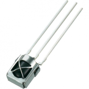
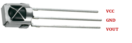
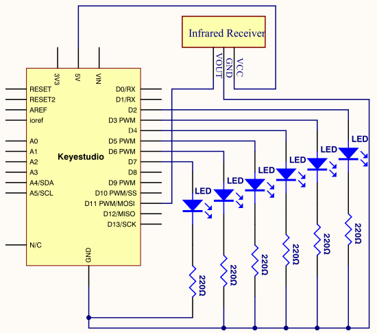
3.Pin and Wiring for Infrared Receiver
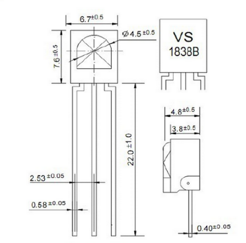
Infrared receiver has 3 pins. When you use it, connect VOUT to analog pin, GND to GND, VCC to +5V.
4.Hardware Required
- V4.0 Board or MEGA 2650 Board*1
- Infrared Remote Controller *1
- Infrared Receiver *1
- LED *6
- 220ΩResistor *6
- Breadboard Wire *11
- USB cable*1
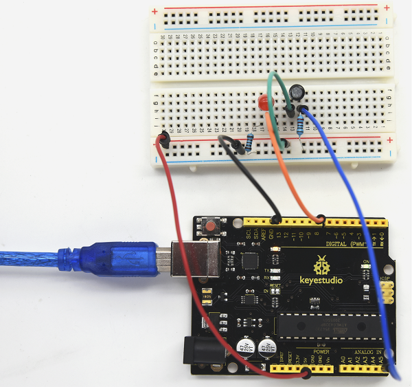
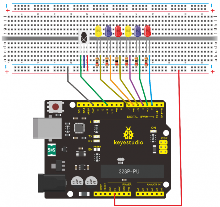
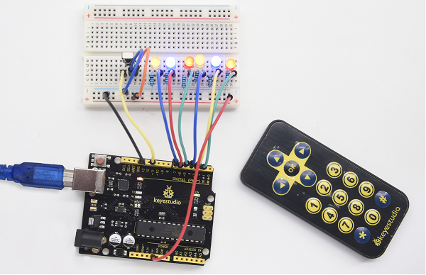
5.Circuit Connection
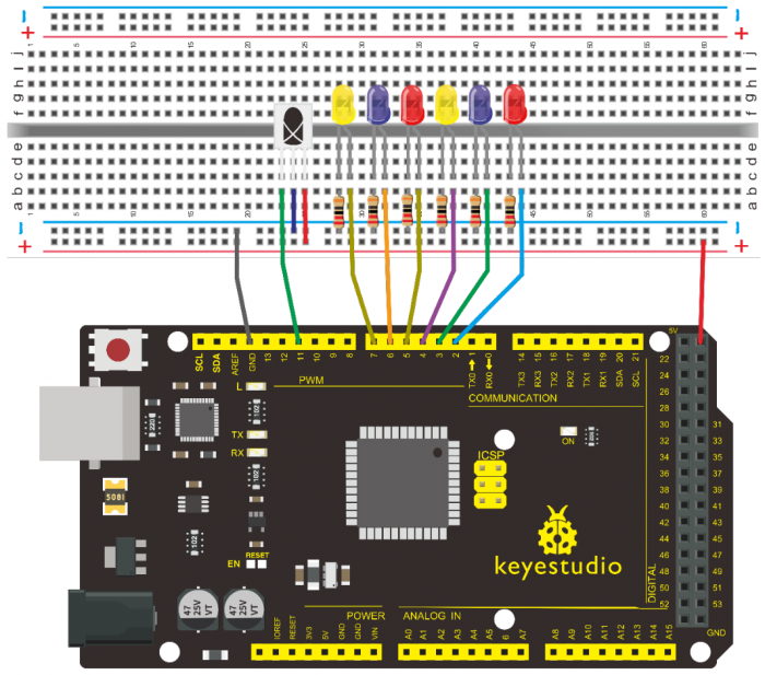
First, connect the controller board; then connect the infrared receiver as the above mentioned, connect VOUT to digital pin 11, connect the LEDs with resistors and connect the resistors to pin 2,3,4,5,6,7.
Connection for V4.0
Connection for 2560
6.Experimental Principle
If you want to decode the code from the remote controller, you must first know how it’s coded. The coding method we use here is NEC protocol. Below is a brief introduction.
• NEC protocol
7.Features
- (1)8 bit address and 8 bit command length
- (2) address and command are transmitted twice for reliability
- (3) pulse distance modulation
- (4) carrier frequency of 38 KHZ
- (5) bit time of 1.125ms or 2.25ms
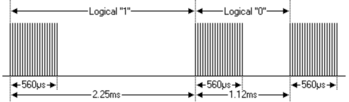
8.Protocol is as below
• Definition of logical 0 and 1 is as below
• Pulse transmitted when button is pressed and immediately released
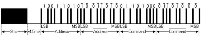
The picture above shows a typical pulse train of the NEC protocol. With this protocol the LSB is transmitted first. In this case Address $59 and Command $16 is transmitted. A message is started by a 9ms AGC burst, which was used to set the gain of the earlier IR receivers. This AGC burst is then followed by a 4.5ms space, which is then followed by the address and command. Address and Command are transmitted twice. The second time all bits are inverted and can be used for verification of the received message. The total transmission time is constant because every bit is repeated with its inverted length. If you are not interested in this reliability, you can ignore the inverted values, or you can expend the Address and Command to 16 bits each!
• Pulse transmitted when button is pressed and released after a period of time
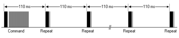
A command is transmitted only once, even when the key on the remote
control remains pressed. Every 110ms a repeat code is transmitted for as long as the key remains down. This repeat code is simply a 9ms AGC pulse followed by a 2.25ms space and a 560µs burst.
• Repeat pulse
Note when the pulse enters the integrated receiver, there will be decoding, signal amplifying and wave shaping process. So you need to make sure the level of the output is just the opposite from that of the signal sending end.
That is when there is no infrared signal, the output end is in high level; when there is infrared signal, the output end is in low level. You can see the pulse of the receiving end in the oscilloscope. Try to better understand the program based on what you see.
9.Sample Code
/*
 keyestudio super learning kit
 Project 14
 Remote
 http//www.keyestudio.com
*/
#include <IRremote.h>
int RECV_PIN = 11;
int LED1 = 2;
int LED2 = 3;
int LED3 = 4;
int LED4 = 5;
int LED5 = 6;
int LED6 = 7;
long on1  = 0x00FF6897;
long off1 = 0x00FF9867;
long on2 = 0x00FFB04F;
long off2 = 0x00FF30CF;
long on3 = 0x00FF18E7;
long off3 = 0x00FF7A85;
long on4 = 0x00FF10EF;
long off4 = 0x00FF38C7;
long on5 = 0x00FF5AA5;
long off5 = 0x00FF42BD;
long on6 = 0x00FF4AB5;
long off6 = 0x00FF52AD;
IRrecv irrecv(RECV_PIN);
decode_results results;
// Dumps out the decode_results structure.
// Call this after IRrecv::decode()
// void * to work around compiler issue
//void dump(void *v) {
//  decode_results *results = (decode_results *)v
void dump(decode_results *results) {
  int count = results->rawlen;
  if (results->decode_type == UNKNOWN)
    {
     Serial.println("Could not decode message");
    }
  else
   {
    if (results->decode_type == NEC)
      {
       Serial.print("Decoded NEC: ");
      }
    else if (results->decode_type == SONY)
      {
       Serial.print("Decoded SONY: ");
      }
    else if (results->decode_type == RC5)
      {
       Serial.print("Decoded RC5: ");
      }
    else if (results->decode_type == RC6)
      {
       Serial.print("Decoded RC6: ");
      }
     Serial.print(results->value, HEX);
     Serial.print(" (");
     Serial.print(results->bits, DEC);
     Serial.println(" bits)");
   }
     Serial.print("Raw (");
     Serial.print(count, DEC);
     Serial.print("): ");
 for (int i = 0; i < count; i++)
     {
      if ((i % 2) == 1) {
      Serial.print(results->rawbuf[i]*USECPERTICK, DEC);
     }
    else
     {
      Serial.print(-(int)results->rawbuf[i]*USECPERTICK, DEC);
     }
    Serial.print(" ");
     }
      Serial.println("");
     }
void setup()
 {
  pinMode(RECV_PIN, INPUT);
  pinMode(LED1, OUTPUT);
  pinMode(LED2, OUTPUT);
  pinMode(LED3, OUTPUT);
  pinMode(LED4, OUTPUT);
  pinMode(LED5, OUTPUT);
  pinMode(LED6, OUTPUT);
  pinMode(13, OUTPUT);
  Serial.begin(9600);
   irrecv.enableIRIn(); // Start the receiver
 }
int on = 0;
unsigned long last = millis();
void loop()
{
  if (irrecv.decode(&results))
   {
    // If it's been at least 1/4 second since the last
    // IR received, toggle the relay
    if (millis() - last > 250)
      {
       on = !on;
//       digitalWrite(8, on ? HIGH : LOW);
       digitalWrite(13, on ? HIGH : LOW);
       dump(&results);
      }
    if (results.value == on1 )
       digitalWrite(LED1, HIGH);
    if (results.value == off1 )
       digitalWrite(LED1, LOW);
    if (results.value == on2 )
       digitalWrite(LED2, HIGH);
    if (results.value == off2 )
       digitalWrite(LED2, LOW);
    if (results.value == on3 )
       digitalWrite(LED3, HIGH);
    if (results.value == off3 )
       digitalWrite(LED3, LOW);
    if (results.value == on4 )
       digitalWrite(LED4, HIGH);
    if (results.value == off4 )
       digitalWrite(LED4, LOW);
    if (results.value == on5 )
       digitalWrite(LED5, HIGH);
    if (results.value == off5 )
       digitalWrite(LED5, LOW);
    if (results.value == on6 )
       digitalWrite(LED6, HIGH);
    if (results.value == off6 )
       digitalWrite(LED6, LOW);
    last = millis();
irrecv.resume(); // Receive the next value
  }
}
//////////////////////////////////////////////////////////////////
Note: add IRremote folder into installation directory Arduinocompiler libraries, or you will fail to compile it.
Infrared remote library https//github.com/shirriff/Arduino-IRremote
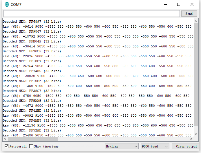
10.Test Result
Decode the coded pulse signal emitted by the remote controller, then execute corresponding action according to the results of the decoding. In this way, you will be able to control your device with remote controller.
Done uploading, open the serial monitor, you can see the result as below.
Project 15: Analog Value Reading
1.Introduction
In this experiment, we will begin the study of analog I/O interfaces. On an Arduino, there are 6 analog interfaces numbered from A0 to A5. Next, let’s begin our project. Potentiometer used here is a typical output component of analog value that is familiar to us.
2.Hardware Required
V4.0 Board or MEGA 2650 Board*1
Potentiometer *1
Breadboard*1
Breadboard Jumper Wire*3
USB cable*1
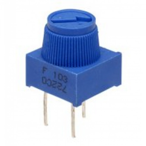
3.Potentiometer Features
Adjustable potentiometer is just a kind of resistor. The resistance is changed by rotating the potentiometer, so is the voltage, speed, brightness and temperature. It is an analog electronic component, which has two states of 0 and 1(high level and low level). The analog quantity is different. Its data state presents a linear state such as 1 to 1000.
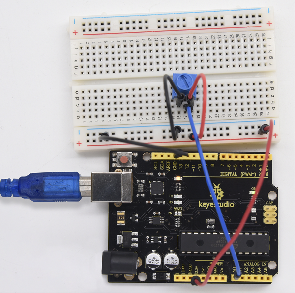
4.Circuit Connection
In this experiment, we will convert the resistance value of the potentiometer to analog ones and display it on the screen.
This is an application you need to master well for our future experiments.
Connection for V4.0
Connection for 2560
5.Sample Code
The program compiling is simple. An analogRead () Statement can read the value of the interface. The A/D acquisition of Arduino 328 is in 10 bits, so the value it reads is among 0 to 1023.
One difficulty in this project is to display the value on the screen, which is actually easy to learn.
First, you need to set the baud rate in voidsetup (). Displaying the value is a communication between Arduino and PC, so the baud rate of the Arduino should match the one in the PC’s software set up. Otherwise, the display will be messy codes or no display at all.
In the lower right corner of the Arduino software monitor window, there is a button for baud rate set up. The set up here needs to match the one in the program. The statement in the program is Serial.begin(); enclosed is the baud rate value, followed by statement for displaying. You can either use Serial.print() or Serial.println() statement.
/*
 keyestudio super learning kit
 Project 15
 Potentiometer
 http//www.keyestudio.com
*/
int potpin=0;// initialize analog pin 0
int ledpin=13;// initialize digital pin 13
int val=0;// define val, assign initial value 0
void setup()
{
pinMode(ledpin,OUTPUT);// set digital pin as “output”
Serial.begin(9600);// set baud rate at 9600
}
void loop()
{
digitalWrite(ledpin,HIGH);// turn on the LED on pin 13
delay(50);// wait for 0.05 second
digitalWrite(ledpin,LOW);// turn off the LED on pin 13
delay(50);// wait for 0.05 second
val=analogRead(potpin);// read the analog value of analog pin 0, and assign it to val
Serial.println(val);// display val’s value
}
//////////////////////////////////////////////////////////////////
6.Test Result
The Sample Code uses the built-in LED connected to pin 13.
Each time the device reads a value, the LED blinks. When you rotate the potentiometer knob, you can see the displayed value change. The reading of analog value is a very common function since most sensors output analog value. After calculation, you can get the corresponding value you need.
Below figure shows the analog value it reads.
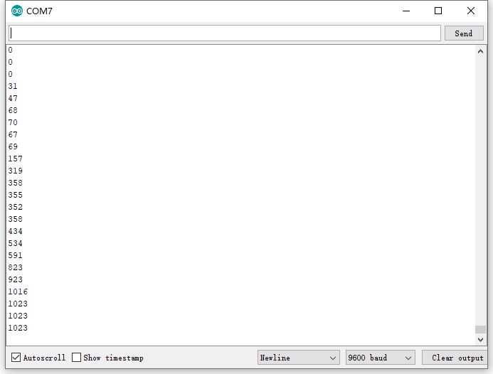
The experiment is now completed. Thank you!
Project 16: 74HC595 chip
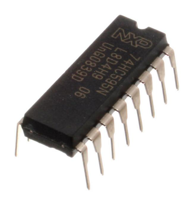
1.Introduction
74HC595 chip is a serial output and parallel output device. To put it simply, 74HC595 chip is a combination of 8-digit shifting register, memorizer and equipped with tri-state output.
Here, we use it to control 8 LEDs. You may wonder why use a 74HC595 to control LED? Well, think about how many I/O it takes for an Arduino to control 8 LEDs? Yes, 8.
For an Arduino 328, it has only 20 I/O including analog ports. To save port resources, using 74HC595 enables us to use 3 digital I/O ports to control 8 LEDs!
2.Hardware Required
- V4.0 Board or MEGA 2650 Board*1
- 74HC595 chip*1
- Red M5 LED*4
- Green M5 LED*4
- 220Ω Resistor*8
- Breadboard*1
- Breadboard Jumper Wires
- USB cable*1
3.Pins Description:
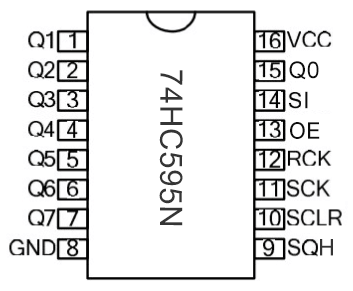
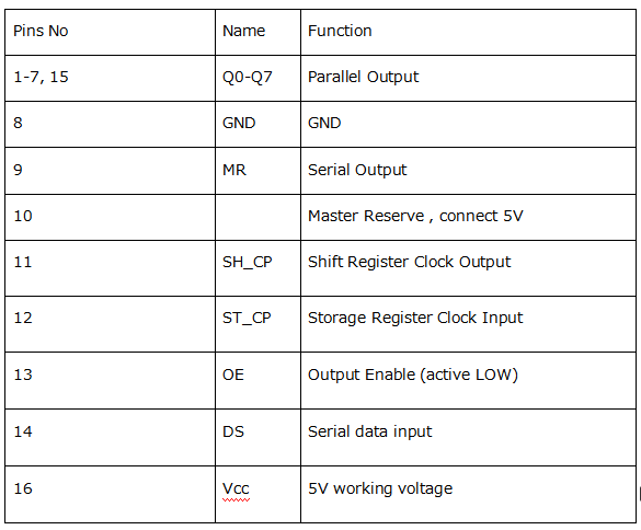
- VCC and GND are used to supply power for chip, the working voltage is 5V.
- Q0~Q7:This eight pins are output pins.
- DS pin is serial input pin, we need to write data into this pin by bit.
- STCP is a latch pin. The data can be copied to latch and output in parallel after 8-digit data of latch is all transmitted.
- SHCP is a clock pin. The data can be written into storage register.
- OE is an output enable pin, which is used to make sure if the data of latch is input into Q0-Q7 pins. When in low level, high level is not output. In this experiment, we directly connect to GND to keep low level output data.
- MR is a pin to initialize the pin of storage register. Initialize the internal storage register when low level. In this experiment, we connect to VCC to keep high level.
- Q7S pin is a serial output pin, which is specially used for chip cascade.
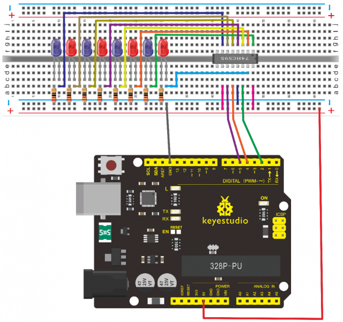
4.Circuit Connection
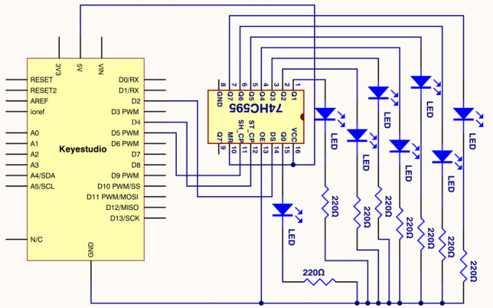
Connection for V4.0
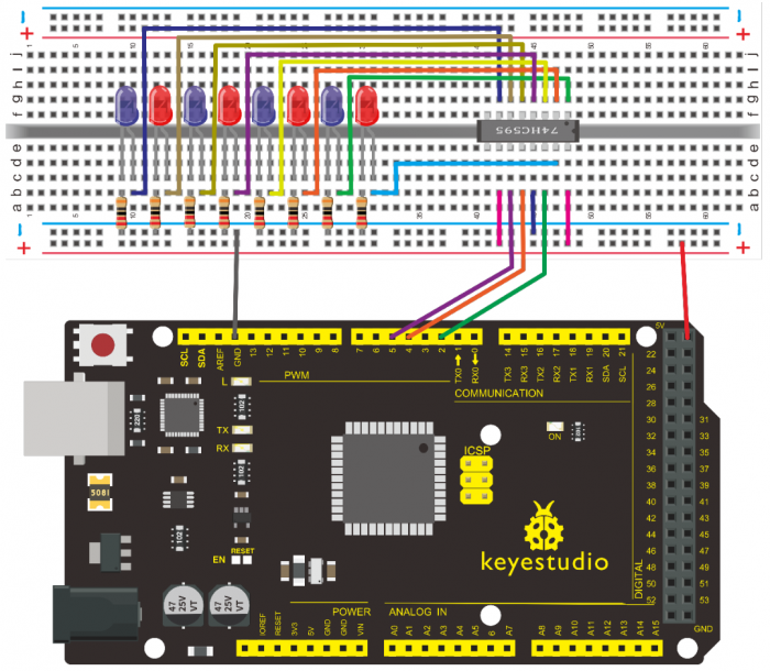
Connection for 2560 R3
The circuit may seem complicated, but once you wire it in order, you will find it more easier!
5.Sample Code
/*
 keyestudio super learning kit
 Project 16
 74hc595
 http//www.keyestudio.com
*/
int data = 2;// set pin 14 of 74HC595as data input pin SI
int clock = 5;// set pin 11 of 74hc595 as clock pin SCK
int latch = 4;// set pin 12 of 74hc595 as output latch RCK
int ledState = 0;
const int ON = HIGH;
const int OFF = LOW;
void setup()
{
pinMode(data, OUTPUT);
pinMode(clock, OUTPUT);
pinMode(latch, OUTPUT);
}
void loop()
{
for(int i = 0; i < 256; i++)
{
updateLEDs(i);
delay(500);
}
}
void updateLEDs(int value)
{
digitalWrite(latch, LOW);//
shiftOut(data, clock, MSBFIRST, ~value);// serial data “output”, high level first
digitalWrite(latch, HIGH);// latch
}
//////////////////////////////////////////////////////////////////
6.Test Result
After downloading the program, you can see 8 LEDs display 8-bit binary number.
Project 17: 1-digit LED Segment Display
1.Introduction
LED segment displays are common for displaying numerical information. It’s widely applied on displays of electromagnetic oven, full automatic washing machine, water temperature display, electronic clock, etc. It is necessary for us to learn how it works.
2.Hardware Required
- V4.0 Board or MEGA 2650 Board*1
- 1-digit LED Segment Display*1
- 220Ω Resistor*8
- Breadboard*1
- Breadboard Jumper Wires *several
- USB cable*1
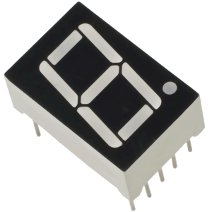
3.The display principle of the 1-digit LED Segment Display
LED segment display is a semiconductor light-emitting device. Its basic unit is a light-emitting diode (LED).
LED segment display can be divided into 7-segment display and 8-segment display according to the number of segments. 8-segment display has one more LED unit ( for decimal point display) than 7-segment one.
According to the wiring method of LED units, LED segment display can be divided into common anode display and common cathode display. Common anode display refers to the one that combine all the anodes of LED units into one common anode (COM).
For the common anode display, connect the common anode (COM) to +5V. When the cathode level of a certain segment is low, the segment is on; when the cathode level of a certain segment is high, the segment is off.
For the common cathode display, connect the common cathode (COM) to GND. When the anode level of a certain segment is high, the segment is on; when the anode level of a certain segment is low, the segment is off.
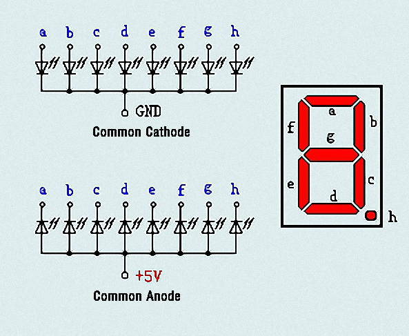
Each segment of the display consists of an LED. So when you use it, you also need to use a current-limiting resistor. Otherwise, LED will be burnt out.
In this experiment, we use a common cathode display. As we mentioned above, for common cathode display, connect the common cathode (COM) to GND. When the anode level of a certain segment is high, the segment is on; when the anode level of a certain segment is low, the segment is off.
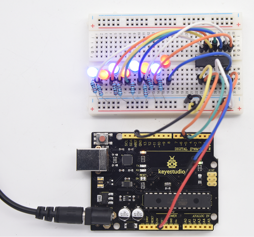
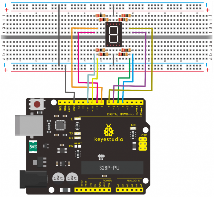
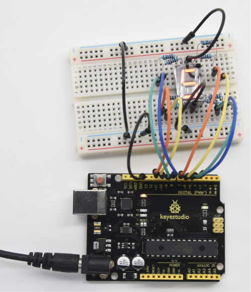
4.Circuit Connection
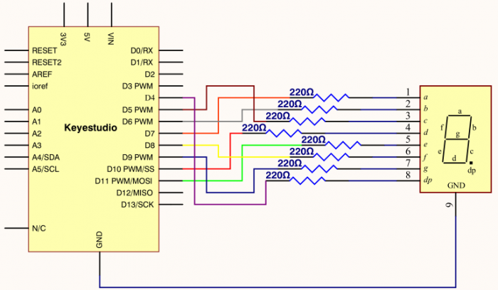
Connection for V4.0
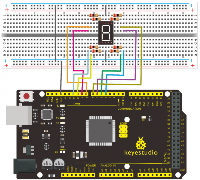
Connection for 2560
5.Sample Code
There are seven segments for numerical display, one for decimal point display. Corresponding segments will be turned on when displaying certain numbers.
For example, when displaying number 1, b and c segments will be turned on. We compile a subprogram for each number, and compile the main program to display one number every 2 seconds, cycling display number 0 ~ 9.
The displaying time for each number is subject to the delay time, the longer the delay time, the longer the displaying time.
/*
keyestudio super learning kit
Project 17
1-digit LED Segment Display
http//www.keyestudio.com
*/
// set the IO pin for each segment
int a=7;// set digital pin 7 for segment a
int b=6;// set digital pin 6 for segment b
int c=5;// set digital pin 5 for segment c
int d=10;// set digital pin 10 for segment d
int e=11;// set digital pin 11 for segment e
int f=8;// set digital pin 8 for segment f
int g=9;// set digital pin 9 for segment g
int dp=4;// set digital pin 4 for segment dp
void digital_0(void) // display number 5
{
unsigned char j;
digitalWrite(a,HIGH);
digitalWrite(b,HIGH);
digitalWrite(c,HIGH);
digitalWrite(d,HIGH);
digitalWrite(e,HIGH);
digitalWrite(f,HIGH);
digitalWrite(g,LOW);
digitalWrite(dp,LOW);
}
void digital_1(void) // display number 1
{
unsigned char j;
digitalWrite(c,HIGH);// set level as “high” for pin 5, turn on segment c
digitalWrite(b,HIGH);// turn on segment b
for(j=7;j<=11;j++)// turn off other segments
digitalWrite(j,LOW);
digitalWrite(dp,LOW);// turn off segment dp
}
void digital_2(void) // display number 2
{
unsigned char j;
digitalWrite(b,HIGH);
digitalWrite(a,HIGH);
for(j=9;j<=11;j++)
digitalWrite(j,HIGH);
digitalWrite(dp,LOW);
digitalWrite(c,LOW);
digitalWrite(f,LOW);
}
void digital_3(void) // display number 3
{digitalWrite(g,HIGH);
digitalWrite(a,HIGH);
digitalWrite(b,HIGH);
digitalWrite(c,HIGH);
digitalWrite(d,HIGH);
digitalWrite(dp,LOW);
digitalWrite(f,LOW);
digitalWrite(e,LOW);
}
void digital_4(void) // display number 4
{digitalWrite(c,HIGH);
digitalWrite(b,HIGH);
digitalWrite(f,HIGH);
digitalWrite(g,HIGH);
digitalWrite(dp,LOW);
digitalWrite(a,LOW);
digitalWrite(e,LOW);
digitalWrite(d,LOW);
}
void digital_5(void) // display number 5
{
unsigned char j;
digitalWrite(a,HIGH);
digitalWrite(b, LOW);
digitalWrite(c,HIGH);
digitalWrite(d,HIGH);
digitalWrite(e, LOW);
digitalWrite(f,HIGH);
digitalWrite(g,HIGH);
digitalWrite(dp,LOW);
}
void digital_6(void) // display number 6
{
unsigned char j;
for(j=7;j<=11;j++)
digitalWrite(j,HIGH);
digitalWrite(c,HIGH);
digitalWrite(dp,LOW);
digitalWrite(b,LOW);
}
void digital_7(void) // display number 7
{
unsigned char j;
for(j=5;j<=7;j++)
digitalWrite(j,HIGH);
digitalWrite(dp,LOW);
for(j=8;j<=11;j++)
digitalWrite(j,LOW);
}
void digital_8(void) // display number 8
{
unsigned char j;
for(j=5;j<=11;j++)
digitalWrite(j,HIGH);
digitalWrite(dp,LOW);
}
void digital_9(void) // display number 5
{
unsigned char j;
digitalWrite(a,HIGH);
digitalWrite(b,HIGH);
digitalWrite(c,HIGH);
digitalWrite(d,HIGH);
digitalWrite(e, LOW);
digitalWrite(f,HIGH);
digitalWrite(g,HIGH);
digitalWrite(dp,LOW);
}
void setup()
{
int i;// set variable
for(i=4;i<=11;i++)
pinMode(i,OUTPUT);// set pin 4-11as “output”
}
void loop()
{
while(1)
{
digital_0();// display number 0
delay(1000);// wait for 1s
digital_1();// display number 1
delay(1000);// wait for 1s
digital_2();// display number 2
delay(1000); // wait for 1s
digital_3();// display number 3
delay(1000); // wait for 1s
digital_4();// display number 4
delay(1000); // wait for 1s
digital_5();// display number 5
delay(1000); // wait for 1s
digital_6();// display number 6
delay(1000); // wait for 1s
digital_7();// display number 7
delay(1000); // wait for 1s
digital_8();// display number 8
delay(1000); // wait for 1s
digital_9();// display number 9
delay(1000); // wait for 1s
}}
//////////////////////////////////////////////////////////////////
6.Test Result
LED segment display will show the number from 0 to 9.
Project 18: 4-digit LED Segment Display
1.Introduction
In this experiment, we use an Arduino to drive a common cathode, 4-digit, 7-segment LED display.
For LED display, current-limiting resistors are indispensable.
There are two wiring methods for Current-limiting resistor. One is to connect one resistor for each cathode end, 4 in total for d1-d4 cathode. An advantage for this method is that it requires fewer resistors, only 4. But it cannot maintain consistent brightness, 1, the brightest; 8, the least bright.
Another method is to connect one resistor to each pin. It guarantees consistent brightness, but requires more resistors.
In this experiment, we use 8 Resistors (220Ω). We use 220ΩResistors because of no 100Ω resistor available. If you use 100Ω, the displaying is more brighter.
2.Hardware Required
- V4.0 Board or MEGA 2650 Board*1
- 4-digit LED Segment Display*1
- 220Ω Resistor*8
- Breadboard*1
- Breadboard Jumper Wires *several
- USB cable*1
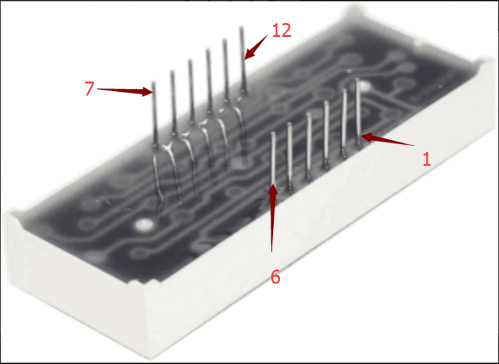
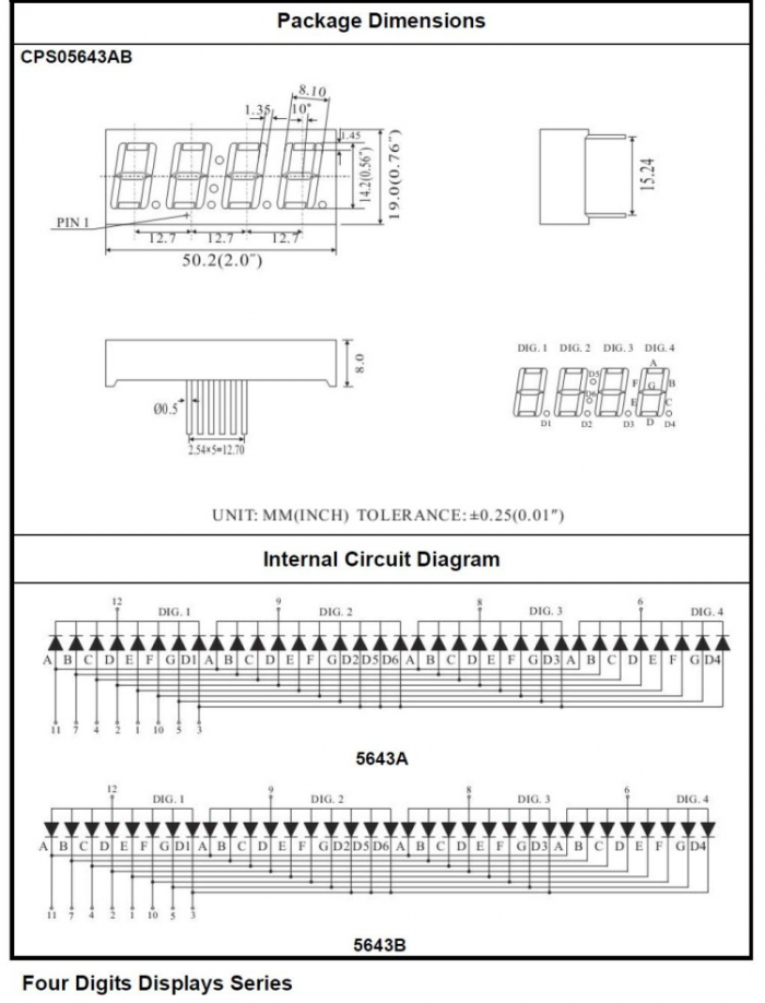
3.The display principle of the 4-digit display
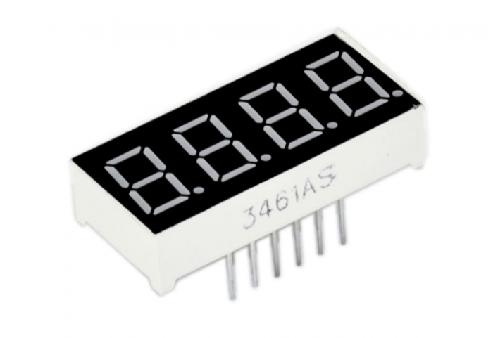
For 4-digit display, there are 12 pins in total. When you place the decimal point downward, the pin on the lower left part is refer to as 1, the upper left part 12. Shown below.
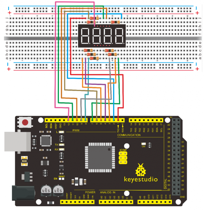
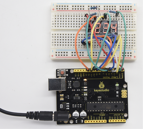
4.Circuit Connection
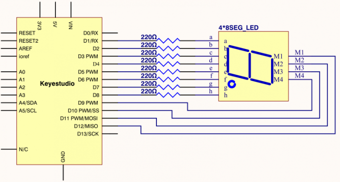
Connection for V4.0
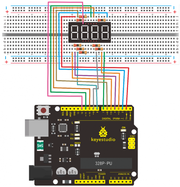
Connection for 2560 R3
5.Sample Code
/*
 keyestudio super learning kit
 Project 18
 4-digit LED Segment Display
 http//www.keyestudio.com
*/
// display 1234
  // select pin for cathode
  int a = 1;
  int b = 2;
  int c = 3;
  int d = 4;
  int e = 5;
  int f = 6;
  int g = 7;
  int dp = 8;
  // select pin for anode
  int d4 = 9;
  int d3 = 10;
  int d2 = 11;
  int d1 = 12;
  // set variable
  long n = 1230;
  int x = 100;
  int del = 55;  // fine adjustment for clock

  void setup()
  {
    pinMode(d1, OUTPUT);
    pinMode(d2, OUTPUT);
    pinMode(d3, OUTPUT);
    pinMode(d4, OUTPUT);
    pinMode(a, OUTPUT);
    pinMode(b, OUTPUT);
    pinMode(c, OUTPUT);
    pinMode(d, OUTPUT);
    pinMode(e, OUTPUT);
    pinMode(f, OUTPUT);
    pinMode(g, OUTPUT);
    pinMode(dp, OUTPUT);
  }
/////////////////////////////////////////////////////////////
void loop()
{
 Display(1, 1);
 Display(2, 2);
 Display(3, 3);
 Display(4, 4);

}
///////////////////////////////////////////////////////////////
void WeiXuan(unsigned char n)//
{
    switch(n)
     {
  case 1:
    digitalWrite(d1,LOW);
    digitalWrite(d2, HIGH);
    digitalWrite(d3, HIGH);
    digitalWrite(d4, HIGH);
   break;
   case 2:
    digitalWrite(d1, HIGH);
    digitalWrite(d2, LOW);
    digitalWrite(d3, HIGH);
    digitalWrite(d4, HIGH);
      break;
    case 3:
      digitalWrite(d1,HIGH);
     digitalWrite(d2, HIGH);
     digitalWrite(d3, LOW);
     digitalWrite(d4, HIGH);
      break;
    case 4:
     digitalWrite(d1, HIGH);
     digitalWrite(d2, HIGH);
     digitalWrite(d3, HIGH);
     digitalWrite(d4, LOW);
      break;
        default :
           digitalWrite(d1, HIGH);
     digitalWrite(d2, HIGH);
     digitalWrite(d3, HIGH);
     digitalWrite(d4, HIGH);
        break;
    }
}
void Num_0()
{
  digitalWrite(a, HIGH);
  digitalWrite(b, HIGH);
  digitalWrite(c, HIGH);
  digitalWrite(d, HIGH);
  digitalWrite(e, HIGH);
  digitalWrite(f, HIGH);
  digitalWrite(g, LOW);
  digitalWrite(dp,LOW);
}
void Num_1()
{
  digitalWrite(a, LOW);
  digitalWrite(b, HIGH);
  digitalWrite(c, HIGH);
  digitalWrite(d, LOW);
  digitalWrite(e, LOW);
  digitalWrite(f, LOW);
  digitalWrite(g, LOW);
  digitalWrite(dp,LOW);
}
void Num_2()
{
  digitalWrite(a, HIGH);
  digitalWrite(b, HIGH);
  digitalWrite(c, LOW);
  digitalWrite(d, HIGH);
  digitalWrite(e, HIGH);
  digitalWrite(f, LOW);
  digitalWrite(g, HIGH);
  digitalWrite(dp,LOW);
}
void Num_3()
{
  digitalWrite(a, HIGH);
  digitalWrite(b, HIGH);
  digitalWrite(c, HIGH);
  digitalWrite(d, HIGH);
  digitalWrite(e, LOW);
  digitalWrite(f, LOW);
  digitalWrite(g, HIGH);
  digitalWrite(dp,LOW);
}
void Num_4()
{
  digitalWrite(a, LOW);
  digitalWrite(b, HIGH);
  digitalWrite(c, HIGH);
  digitalWrite(d, LOW);
  digitalWrite(e, LOW);
  digitalWrite(f, HIGH);
  digitalWrite(g, HIGH);
  digitalWrite(dp,LOW);
}
void Num_5()
{
  digitalWrite(a, HIGH);
  digitalWrite(b, LOW);
  digitalWrite(c, HIGH);
  digitalWrite(d, HIGH);
  digitalWrite(e, LOW);
  digitalWrite(f, HIGH);
  digitalWrite(g, HIGH);
  digitalWrite(dp,LOW);
}
void Num_6()
{
  digitalWrite(a, HIGH);
  digitalWrite(b, LOW);
  digitalWrite(c, HIGH);
  digitalWrite(d, HIGH);
  digitalWrite(e, HIGH);
  digitalWrite(f, HIGH);
  digitalWrite(g, HIGH);
  digitalWrite(dp,LOW);
}
void Num_7()
{
  digitalWrite(a, HIGH);
  digitalWrite(b, HIGH);
  digitalWrite(c, HIGH);
  digitalWrite(d, LOW);
  digitalWrite(e, LOW);
  digitalWrite(f, LOW);
  digitalWrite(g, LOW);
  digitalWrite(dp,LOW);
}
void Num_8()
{
  digitalWrite(a, HIGH);
  digitalWrite(b, HIGH);
  digitalWrite(c, HIGH);
  digitalWrite(d, HIGH);
  digitalWrite(e, HIGH);
  digitalWrite(f, HIGH);
  digitalWrite(g, HIGH);
  digitalWrite(dp,LOW);
}
void Num_9()
{
  digitalWrite(a, HIGH);
  digitalWrite(b, HIGH);
  digitalWrite(c, HIGH);
  digitalWrite(d, HIGH);
  digitalWrite(e, LOW);
  digitalWrite(f, HIGH);
  digitalWrite(g, HIGH);
  digitalWrite(dp,LOW);
}
void Clear()  // clear the screen
{
  digitalWrite(a, LOW);
  digitalWrite(b, LOW);
  digitalWrite(c, LOW);
  digitalWrite(d, LOW);
  digitalWrite(e, LOW);
  digitalWrite(f, LOW);
  digitalWrite(g, LOW);
  digitalWrite(dp,LOW);
}
void pickNumber(unsigned char n)// select number
{
  switch(n)
  {
   case 0:Num_0();
   break;
   case 1:Num_1();
   break;
   case 2:Num_2();
   break;
   case 3:Num_3();
   break;
   case 4:Num_4();
   break;
   case 5:Num_5();
   break;
   case 6:Num_6();
   break;
   case 7:Num_7();
   break;
   case 8:Num_8();
   break;
   case 9:Num_9();
   break;
   default:Clear();
   break;
  }
}
void Display(unsigned char x, unsigned char Number)//  take x as coordinate and display number
{
  WeiXuan(x);
  pickNumber(Number);
 delay(1);
 Clear() ; // clear the screen
}
//////////////////////////////////////////////////////////
6.Test Result
Download the above code to the controller board, you can see the LED display shows the number 1234.
Note if it’s not displaying correctly, check the wiring.
Project 19: 8*8 LED Matrix
1.Introduction
LED dot-matrix display can meet the needs of different applications, thus has a broad development prospect. With low-voltage scanning, LED dot-matrix has some advantages such as power saving, long service life, low cost, high brightness, wide angle of view, long visual range, waterproof, and numerous specifications.
This project, we will conduct an LED dot-matrix experiment to experience its charm firsthand.
2.Hardware Required
- V4.0 Board or MEGA 2650 Board*1
- 1 * 8*8 Dot Matrix
- 8 * Resistor (220Ω)
- 1 * Breadboard
- 1 * USB Cable
- Several* Jumper Wires
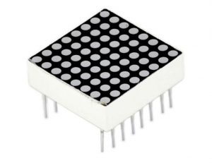
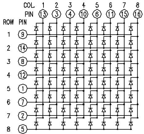
3.The display principle of the 8*8 dot-matrix
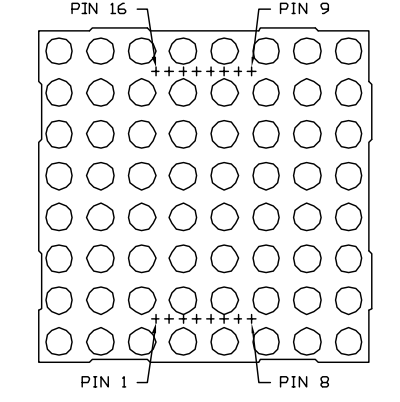
The external view of a dot-matrix is shown as follows
The 8*8 dot-matrix is made up of sixty-four LEDs, and each LED is placed at the cross point of a row and a column.
When the electrical level of a certain row is 1 and the electrical level of a certain column is 0, the corresponding LED will lighten. If you want to light the LED on the first dot, you should set pin 9 to high level and pin 13 to low level.
If you want to light LEDs on the first row, you should set pin 9 to high level and pins 13, 3, 4, 10, 6, 11, 15 and 16 to low level.
If you want to light the LEDs on the first column, set pin 13 to low level and pins 9, 14, 8, 12, 1, 7, 2 and 5 to high level.
The internal view of a dot-matrix is shown as follows
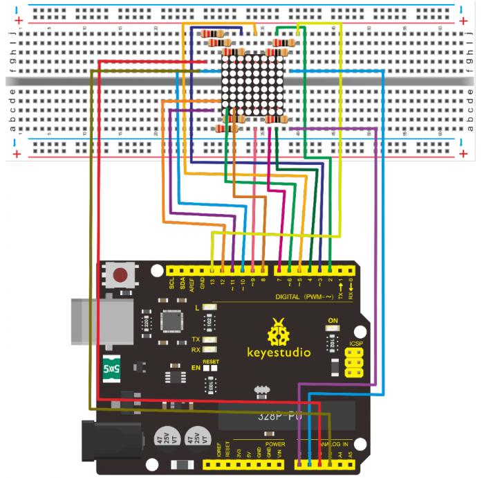
4.Circuit Connection
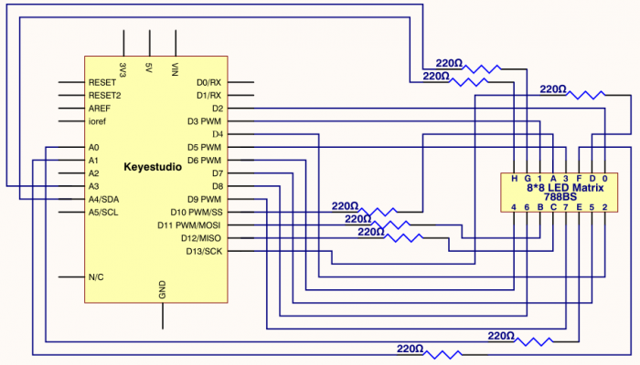
Connection for V4.0
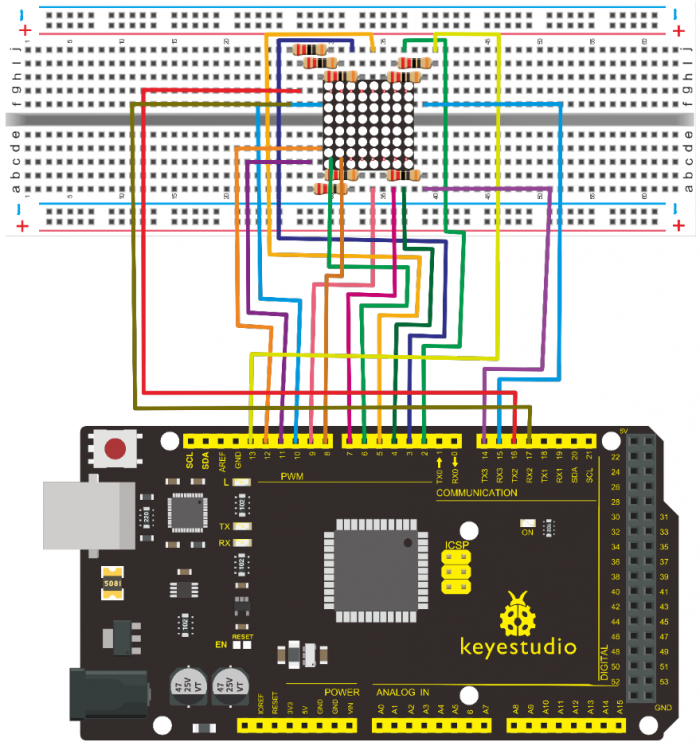
Connection for 2560 R3
5.Sample Code for displaying “0”
/*
 keyestudio super learning kit
 Project 19
 8*8 dot-matrix
 http//www.keyestudio.com
*/
// set an array to store character of “0”
unsigned char Text[]={0x00,0x1c,0x22,0x22,0x22,0x22,0x22,0x1c};
void Draw_point(unsigned char x,unsigned char y)// point drawing function
{ clear_();
   digitalWrite(x+2, HIGH);
   digitalWrite(y+10, LOW);
   delay(1);
}
void show_num(void)// display function, call point drawing function
{
  unsigned char i,j,data;
  for(i=0;i<8;i++)
  {
    data=Text[i];
    for(j=0;j<8;j++)
    {
      if(data & 0x01)Draw_point(j,i);
      data>>=1;
    }
  }
}
void setup(){
int i = 0 ;
for(i=2;i<18;i++)
 {
   pinMode(i, OUTPUT);
  }
  clear_();
}
void loop()
{ show_num();
}
void clear_(void)// clear screen
{for(int i=2;i<10;i++)
  digitalWrite(i, LOW);
  for(int i=0;i<8;i++)
  digitalWrite(i+10, HIGH);
}
//////////////////////////////////////////////////////////
6.Test Result
Burn the program into V4.0 board, the dot-matrix will display 0.
Project 20: 1602 LCD
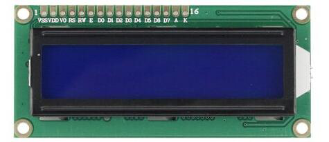
1.Introduction
In this experiment, we use an Arduino to drive the 1602 LCD.
1602 LCD has wide applications. In the beginning, 1602 LCD uses a HD44780 controller.
Now, almost all 1602 LCD module uses a compatible IC, so their features are basically the same.
2.1602LCD Main Parameters
- V4.0 Board or MEGA 2650 Board*1
- Display capacity 16 * 2 characters
- Chip operating voltage 4.5 ~ 5.5V
- Working current 2.0mA (5.0V)
- Optimum working voltage of the module is 5.0V
- Character size 2.95 * 4.35 (W * H) mm
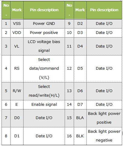
3.Pin description of 1602 LCD
4.Interface Description
- 1.Two power pins, one for module power, another one for back light, generally use 5V. In this project, we use 3.3V for backlight.
- 2.VL is the pin for adjusting contrast ratio. It usually connects a potentiometer(no more than 5KΩ) in series for its adjustment.
- In this experiment, we use a 1KΩ resistor. For its connection, it has two methods, namely high potential and low potential. Here, we use low potential method; connect the resistor and then the GND.
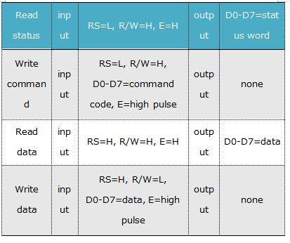
- 3.RS is a very common pin in LCD. It’s a selecting pin for command/data. When the pin is in high level, it’s in data mode; when it’s in low level, it’s in command mode.
- 4.RW pin is also very common in LCD. It’s a selecting pin for read/write. When the pin is in high level, it’s in read operation; if in low level, it’s in write operation.
- 5.E pin is also very common in LCD. Usually, when the signal in the bus is stabilized, it sends out a positive pulse requiring read operation. When this pin is in high level, the bus is not allowed to have any change.
- 6.D0-D7 is 8-bit bidirectional parallel bus, used for command and data transmission.
- 7.BLA is anode for back light; BLK, cathode for back light.
5.Four Basic Operations for 1602LCD
6.Hardware Required
- V4.0 Board or MEGA 2650 Board*1
- 1 * 1602 LCD
- 1 * Potentiometer
- 1 * Breadboard
- 1 * USB Cable
- Several* Jumper Wires
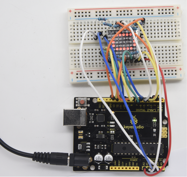
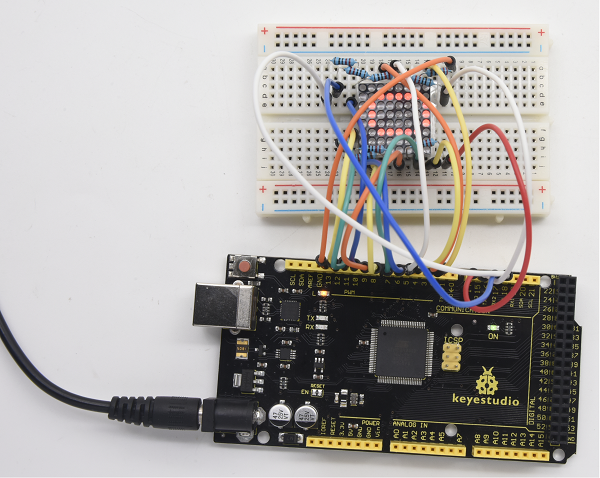
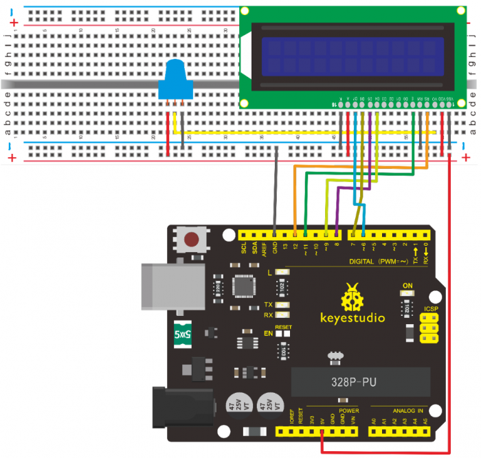
7.Connection
1602 can directly communicate with Arduino. According to the product manual, it has two connection methods, namely 8-bit connection and 4-bit connection.
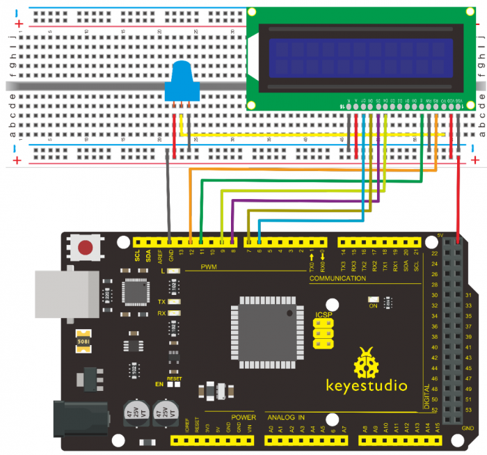
8-bit Connection Method
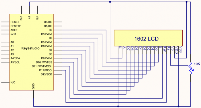
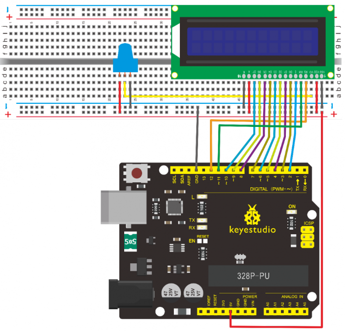
Connection for V4.0
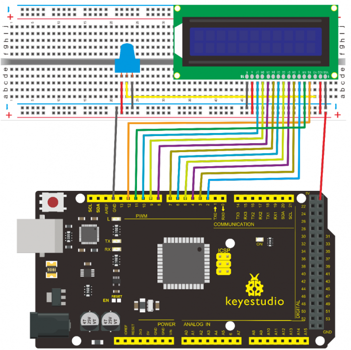
Connection for 2560 R3
8.Sample Code A
/*
keyestudio super learning kit
Project 20.1
LCD1602
http//www.keyestudio.com
*/
int DI = 12;
int RW = 11;
int DB[] = {3, 4, 5, 6, 7, 8, 9, 10};// use array to select pin for bus
int Enable = 2;
void LcdCommandWrite(int value) {
// define all pins
int i = 0;
for (i=DB[0]; i <= DI; i++) // assign value for bus
{
digitalWrite(i,value & 01);// for 1602 LCD, it uses D7-D0( not D0-D7) for signal identification; here, it’s used for signal inversion.
value >>= 1;
}
digitalWrite(Enable,LOW);
delayMicroseconds(1);
digitalWrite(Enable,HIGH);
delayMicroseconds(1); // wait for 1ms
digitalWrite(Enable,LOW);
delayMicroseconds(1); // wait for 1ms
}
void LcdDataWrite(int value) {
// initialize all pins
int i = 0;
digitalWrite(DI, HIGH);
digitalWrite(RW, LOW);
for (i=DB[0]; i <= DB[7]; i++) {
digitalWrite(i,value & 01);
value >>= 1;
}
digitalWrite(Enable,LOW);
delayMicroseconds(1);
digitalWrite(Enable,HIGH);
delayMicroseconds(1);
digitalWrite(Enable,LOW);
delayMicroseconds(1); // wait for 1ms
}
void setup (void) {
int i = 0;
for (i=Enable; i <= DI; i++) {
pinMode(i,OUTPUT);
}
delay(100);
// initialize LCD after a brief pause
// for LCD control
LcdCommandWrite(0x38); // select as 8-bit interface, 2-line display, 5x7 character size
delay(64);
LcdCommandWrite(0x38); // select as 8-bit interface, 2-line display, 5x7 character size
delay(50);
LcdCommandWrite(0x38); // select as 8-bit interface, 2-line display, 5x7 character size
delay(20);
LcdCommandWrite(0x06); // set input mode
// auto-increment, no display of shifting
delay(20);
LcdCommandWrite(0x0E); // display setup
// turn on the monitor, cursor on, no flickering
delay(20);
LcdCommandWrite(0x01); // clear the scree, cursor position returns to 0
delay(100);
LcdCommandWrite(0x80); // display setup
// turn on the monitor, cursor on, no flickering
delay(20);
}
void loop (void) {
LcdCommandWrite(0x01); // clear the scree, cursor position returns to 0
delay(10);
LcdCommandWrite(0x80+3);
delay(10);
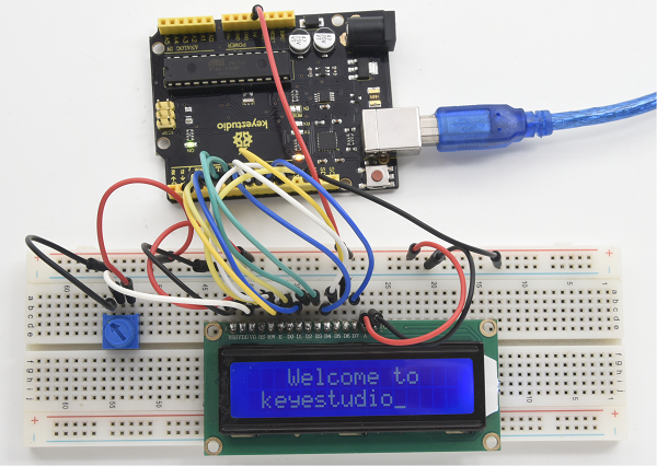
// write in welcome message
LcdDataWrite('W');
LcdDataWrite('e');
LcdDataWrite('l');
LcdDataWrite('c');
LcdDataWrite('o');
LcdDataWrite('m');
LcdDataWrite('e');
LcdDataWrite(' ');
LcdDataWrite('t');
LcdDataWrite('o');
delay(10);
LcdCommandWrite(0xc0+1); // set cursor position at second line, second position
delay(10);
LcdDataWrite('k');
LcdDataWrite('e');
LcdDataWrite('y');
LcdDataWrite('e');
LcdDataWrite('s');
LcdDataWrite('t');
LcdDataWrite('u');
LcdDataWrite('d');
LcdDataWrite('i');
LcdDataWrite('o');
delay(5000);
LcdCommandWrite(0x01); // clear the screen, cursor returns to 0
delay(10);
LcdDataWrite('I');
LcdDataWrite(' ');
LcdDataWrite('a');
LcdDataWrite('m');
LcdDataWrite(' ');
LcdDataWrite('h');
LcdDataWrite('u');
LcdDataWrite('n');
LcdDataWrite('t');
LcdDataWrite('e');
LcdDataWrite('r');
delay(3000);
LcdCommandWrite(0x02); // set mode as new characters replay old ones, where there is no new ones remain the same
delay(10);
LcdCommandWrite(0x80+5); // set cursor position at first line, sixth position
delay(10);
LcdDataWrite('t');
LcdDataWrite('h');
LcdDataWrite('e');
LcdDataWrite(' ');
LcdDataWrite('w');
LcdDataWrite('o');
LcdDataWrite('r');
LcdDataWrite('l');
LcdDataWrite('d');
delay(5000);
}
//////////////////////////////////////////////////////////
4-bit Connection Method
When using this module, 8-bit connection uses all the digital pins of the Arduino, leaving no pin for sensors. What then? You can use 4-bit connection.
Connection for V4.0
Connection for 2560 R3
After the connection, upload below code to the controller board and see how it goes.
9.Sample Code B
/*
keyestudio super learning kit
Project 20.2
LCD1602
http//www.keyestudio.com
*/
/* LCD RS pin to digital pin 12
* LCD Enable pin to digital pin 11
* LCD D4 pin to digital pin 9
* LCD D5 pin to digital pin 8
* LCD D6 pin to digital pin 7
* LCD D7 pin to digital pin 6
* LCD R/W pin to ground
* LCD VSS pin to ground
* LCD VCC pin to 5V
* 10K resistor
* ends to +5V and ground
* wiper to LCD VO pin (pin 3)
This example code is in the public domain.
http//www.arduino.cc/en/Tutorial/LiquidCrystal
*/
// include the library code
#include <LiquidCrystal.h>
// initialize the library with the numbers of the interface pins
LiquidCrystal lcd(12, 11, 9, 8, 7, 6);
void setup() {
// set up the LCD's number of columns and rows
lcd.begin(16, 2);
// Print a message to the LCD.
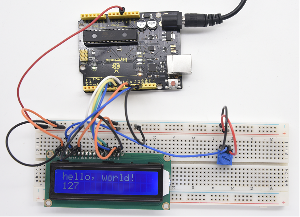
lcd.print("hello, world!");
}
void loop() {
// set the cursor to column 0, line 1
// (note line 1 is the second row, since counting begins with 0)
lcd.setCursor(0, 1);
// print the number of seconds since reset
lcd.print(millis() / 1000);
}
//////////////////////////////////////////////////////////
10. Test Result
Project 21: Servo Control
1.Introduction
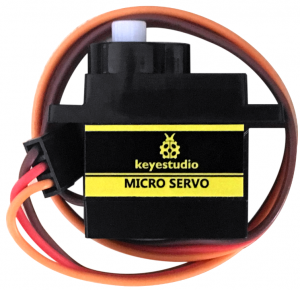
Servomotor is a position control rotary actuator. It mainly consists of housing, circuit board, core-less motor, gear and position sensor. For this lesson, we will introduce servo to you.
2.Working Principle
The MCU outputs a signal to the servomotor. The motor has a built-in reference circuit that gives out reference signal, cycle of 20ms and width of 1.5ms. The motor compares the acquired DC bias voltage to the voltage of the potentiometer and outputs a voltage difference. The IC on the circuit board will decide the rotate direction accordingly and drive the core-less motor. The gear then pass the force to the shaft. The sensor will determine whether it has reached the commanded position according to the feedback signal.
Servomotors are used in control systems that require to have and maintain different angles. When the motor speed is definite, the gear will drive the potentiometer to rotate. When the voltage difference reduces to zero, the motor stops. Normally, the rotation angle range is among 0-180 degrees.
Servomotor comes with many specifications. But all of them have three connection wires, distinguished by brown, red, orange (different brand may have different color).
Brown one is for GND, red one for power positive, orange one for signal line.
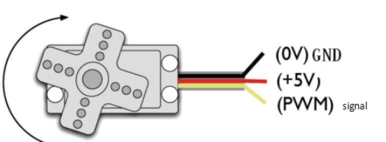
The rotation angle of the servo motor is controlled by regulating the duty cycle of the PWM(Pulse-Width Modulation) signal.
The standard cycle of the PWM signal is 20ms(50Hz). Theoretically, the width is distributed between 1ms-2ms. The width corresponds the rotation angle from 0° to 90°.
But note that for different brand motor, the same signal may have different rotating angle.
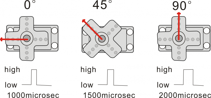
With some basic knowledge, let’s learn how to control a servomotor. In this experiment, you only need a servo motor and several jumper wires.
3.Hardware Required
- V4.0 Board or MEGA 2650 Board*1
- 9G Servo Motor*1
- Breadboard Jumper Wire*3
- USB cable*1
Connection & Sample Code
There are two ways to control a servomotor with Arduino.
One is to use a common digital sensor port of Arduino to produce square wave with different duty cycle to simulate PWM signal and use that signal to control the positioning of the motor.
Another way is to directly use the Servo function of the Arduino to control the motor. In this way, the program will be more easier but it can only control two-contact motor because of the servo function, only digital pin 9 and 10 can be used.
The Arduino drive capacity is limited. So if you need to control more than one motor, you will need external power.
4.Method 1
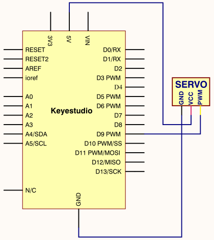
Connection for V4.0
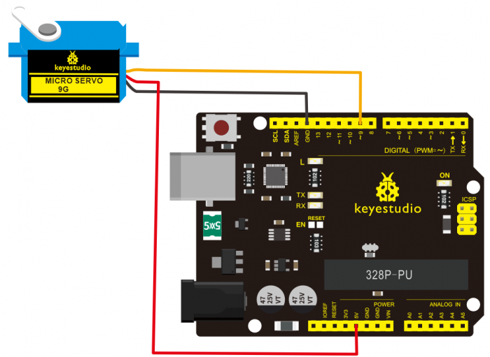
Connection for 2560 R3
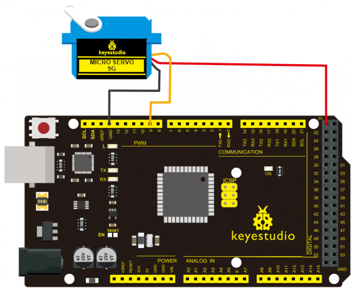
Connect the motor to digital pin 9.
Compile a program to control the motor to rotate in the commanded angle, and display the angle on the screen.
Sample Code A
/*
 keyestudio super learning kit
 Project 21.1
 servo
 http//www.keyestudio.com
*/
int servopin=9;// select digital pin 9 for servomotor signal line
int myangle;// initialize angle variable
int pulsewidth;// initialize width variable
int val;
void servopulse(int servopin,int myangle)// define a servo pulse function
{
pulsewidth=(myangle*11)+500;// convert angle to 500-2480 pulse width
digitalWrite(servopin,HIGH);// set the level of servo pin as “high”
delayMicroseconds(pulsewidth);// delay microsecond of pulse width
digitalWrite(servopin,LOW);// set the level of servo pin as “low”
delay(20-pulsewidth/1000);
}
void setup()
{
pinMode(servopin,OUTPUT);// set servo pin as “output”
Serial.begin(9600);// connect to serial port, set baud rate at “9600”
Serial.println("servo=o_seral_simple ready" ) ;
}
void loop()// convert number 0 to 9 to corresponding 0-180 degree angle, LED blinks corresponding number of time
{
val=Serial.read();// read serial port value
if(val>='0'&&val<='9')
{
val=val-'0';// convert characteristic quantity to numerical variable
val=val*(180/9);// convert number to angle
Serial.print("moving servo to ");
Serial.print(val,DEC);
Serial.println();
for(int i=0;i<=50;i++) // giving the servo time to rotate to commanded position
{
servopulse(servopin,val);// use the pulse function
}}}
//////////////////////////////////////////////////////////
5.Method 2
Let’s first take a look at the Arduino built-in servo function and some common statements.
1. attach(interface)——select pin for servo, can only use pin 9 or 10.
2. write(angle)——used to control the rotate angle of the servo, can set the angle among 0 degree to 180 degree.
3. read()——used to read the angle of the servo, consider it a function to read the value in the write() function.
4. attached()——determine whether the parameter of the servo is sent to the servo pin.
5. detach()—— disconnect the servo and the pin, and the pin (digital pin 9 or 10) can be used for PWM port.
Note the written form of the above statements are » servo variable name. specific statement ()», e.g. myservo. Attach (9).
Still, connect the servo to pin 9.
Sample Code B
/*
 keyestudio super learning kit
 Project 21.2
 servo
 http//www.keyestudio.com
*/
#include <Servo.h>
Servo myservo;// define servo variable name
void setup()
{
myservo.attach(9);// select servo pin(9 or 10)
}
void loop()
{
myservo.write(90);// set rotate angle of the motor
}
//////////////////////////////////////////////////////////
Above are the two methods to control the servo. You can choose either one according to your liking or actual need.
6.Test Result
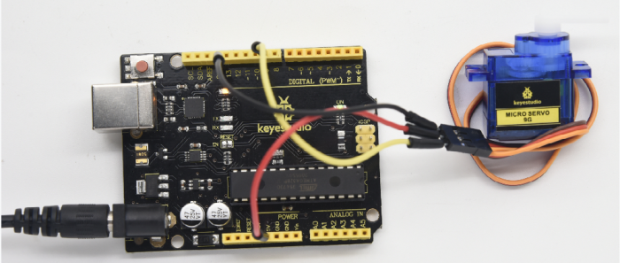
Project 22: Stepper Motor
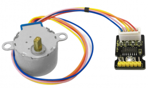
1.Introduction
A stepper motor is an electromechanical device which can convert electrical pulses into discrete mechanical movements. The shaft or spindle of a stepper motor rotates in discrete step increments when electrical command pulses are applied to it in the proper sequence.
The motors rotation has several direct relationships to these applied input pulses. The sequence of the applied pulses is directly related to the direction of motor shafts rotation. The speed of the motor shafts rotation is directly related to the frequency of the input pulses and the length of rotation is directly related to the number of input pulses applied.
One of the most significant advantages of a stepper motor is its ability to be accurately controlled in an open loop system. Open loop control means no feedback information about position is needed. This type of control eliminates the need for expensive sensing and feedback devices such as optical encoders. Your position is known simply by keeping track of the input step pulses.
2.Hardware Required
- V4.0 Board or MEGA 2650 Board*1
- Stepper Motor*1
- Stepper Motor driver*1
- Jumper Wire *1
- USB cable*1
3.Features
- •The rotation angle of the motor is proportional to the input pulse.
- •The motor has full torque at standstill(if the windings are energized)
- •Precise positioning and repeatability of movement since good stepper motors have an accuracy of – 5% of a step and this error is non cumulative from one step to the next.
- •Excellent response to starting/stopping/reversing.
- •Very reliable since there are no contact brushes in the motor. Therefore the life of the motor is simply dependant on the life of the bearing.
- •The motors response to digital input pulses provides open-loop control, making the motor simpler and less costly to control.
- •It is possible to achieve very low speed synchronous rotation with a load that is directly coupled to the shaft.
- •A wide range of rotational speeds can be realized as the speed is proportional to the frequency of the input pulses.
4.Parameters of Stepper Motor 28BYJ-48
•Model 28BYJ-48
•Rated Voltage 5VDC
•Number of Phase 4
•Speed Variation Ratio 1/64
•Stride Angle 5.625° /64
•Frequency 100Hz
•DC Resistance 50Ω±7%(25℃)
•Idle In-traction Frequency > 600Hz
•Idle Out-traction Frequency > 1000Hz
•In-traction Torque >34.3mN.m(120Hz)
•Self-positioning Torque >34.3mN.m
•Friction Torque 600-1200 gf.cm
•Pull in Torque 300 gf.cm
•Insulated Resistance >10MΩ(500V)
•Insulated Electricity Power 600VAC/1mA/1s
•Insulation Grade A
•Rise in Temperature <40K(120Hz)
•Noise <35dB(120Hz,No load,10cm)
5.Circuit Connection
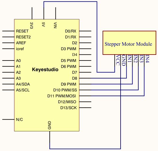
Connection for V4.0
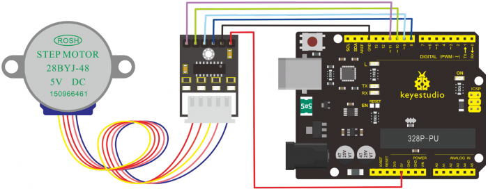
Connection for 2560 R3
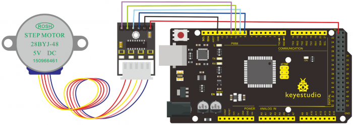
6.Sample Code
/*
 keyestudio super learning kit
 Project 22
 Stepper Motor
 http//www.keyestudio.com
*/
#include <Stepper.h>
#define STEPS 100
Stepper stepper(STEPS, 8, 9, 10, 11);
int previous = 0;
void setup()
{
  stepper.setSpeed(90);
 }
 void loop()
 {
   int val = analogRead(0);
   stepper.step(val - previous);
   previous = val;
 }
//////////////////////////////////////////////////////////
7.Test Result
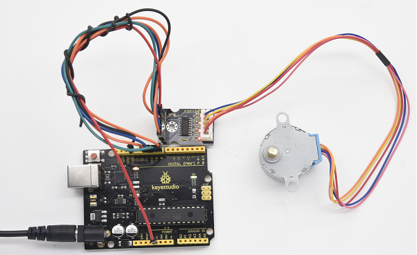
Project 23: PIR Motion Sensor
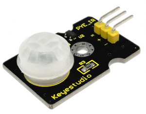
1.Introduction
Pyroelectric infrared motion sensor can detect infrared signals from a moving person or moving animal, and output switching signals.
It can be applied to a variety of occasions to detect the movement of human body.
Conventional pyroelectric infrared sensors require body pyroelectric infrared detector, professional chip, complex peripheral circuit, so it is more bigger with complex circuit, and lower reliability.
Now we launch this new pyroelectric infrared motion sensor, which is specially designed for Arduino.
It uses an integrated digital body pyroelectric infrared sensor, and has smaller size, higher reliability, lower power consumption as well as simpler peripheral circuit.
2.Hardware Required
- V4.0 Board or MEGA 2650 Board*1
- PIR Motion Sensor*1
- Jumper Wire *1
- USB cable*1
3.Specification
•Input Voltage 3.3 ~ 5V (6V Maximum)
•Working Current 15uA
•Working Temperature -20 ~ 85 ℃
•Output Voltage High 3V, Low 0V
•Output Delay Time (High Level) About 2.3 to 3 Seconds
•Detection Angle 100 °
•Detection Distance 7 meters
•Output Indicator LED (When output HIGH, it will be ON)
•Pin limit Current 100mA
4.Circuit Connection
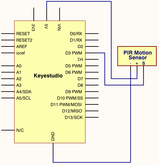
Connection for V4.0
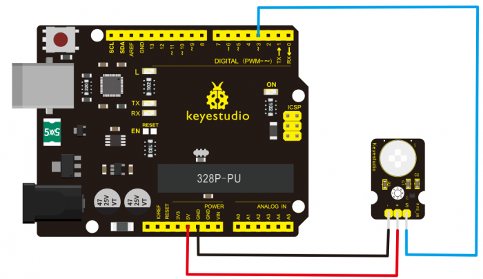
Connection for MEGA 2560 R3
thumb
5.Sample Code
/*
 keyestudio super learning kit
 Project 23
 PIR
 http//www.keyestudio.com
*/
byte sensorPin = 3;
byte indicator = 13;
void setup()
{
  pinMode(sensorPin,INPUT);
  pinMode(indicator,OUTPUT);
  Serial.begin(9600);
}
void loop()
{
  byte state = digitalRead(sensorPin);
  digitalWrite(indicator,state);
  if(state == 1)Serial.println("Somebody is in this area!");
  else if(state == 0)Serial.println("No one!");
  delay(500);
}
//////////////////////////////////////////////////////////
6.Test Result
If the sensor detects someone moving nearby, D13 indicator on V4.0 board will light up, and «Somebody is in this area!» is displayed on the serial monitor.
If no detecting the movement, D13 indicator on V4.0 board will be off, and «No one!» is displayed on the serial monitor.
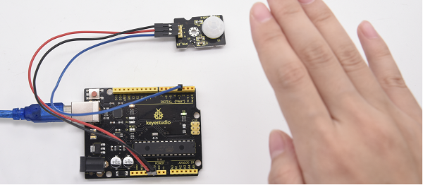
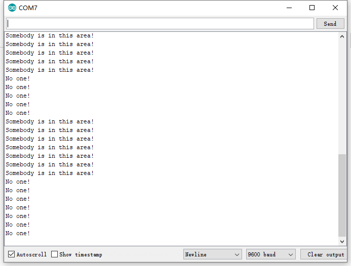
Project 24: Analog Gas Sensor
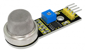
1.Introduction
This analog gas sensor — MQ2 is used in gas leakage detecting equipment in consumer electronics and industrial markets.
This sensor is suitable for LPG, I-butane, propane, methane, alcohol, Hydrogen and smoke detection. It has high sensitivity and quick response. In addition, the sensitivity can be adjusted by the potentiometer.
2.Hardware Required
- V4.0 Board or MEGA 2650 Board*1
- Analog Gas Sensor*1
- Jumper Wire *1
- USB cable*1
3.Specification
•Power Supply 5V
•Interface Type Analog
•Wide detecting scope
•Quick response and high sensitivity
•Simple drive circuit
•Stable and long lifespan
4.Circuit Connection
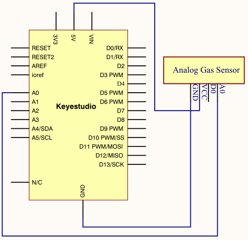
Connection for V4.0
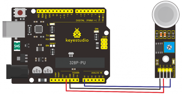
Connection for MEGA 2560 R3
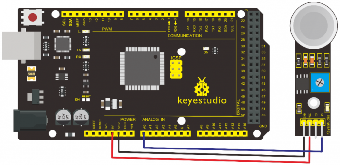
5.Sample Code
/*
 keyestudio super learning kit
 Project 24
 Gas
 http//www.keyestudio.com
*/
void setup()
{
  Serial.begin(9600); //Set serial baud rate to 9600 bps
}
void loop()
{int val;
val=analogRead(0);//Read Gas value from analog 0
Serial.println(val,DEC);//Print the value to serial port
delay(100);
}
//////////////////////////////////////////////////////////
6.Test Result
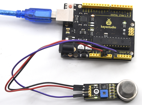
Project 25: ADXL345 Three Axis Acceleration
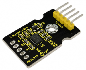
1.Introduction
The ADXL345 is a small, thin, low power, 3-axis MEMS accelerometer with high resolution (13-bit) measurement at up to +-16 g. Digital output data is formatted as 16-bit twos complement and is accessible through either a SPI (3- or 4-wire) or I2C digital interface.
The ADXL345 is well suited to measure the static acceleration of gravity in tilt-sensing applications, as well as dynamic acceleration resulting from motion or shock. Its high resolution (4 mg/LSB) enables measurement of inclination change less than 1.0 degrees.
2.Hardware Required
- V4.0 Board or MEGA 2650 Board*1
- ADXL345 Sensor*1
- Jumper Wire *1
- USB cable*1
3.Specification
•2.0-3.6V DC Supply Voltage
•Ultra Low Power 40uA in measurement mode, 0.1uA in standby@ 2.5V
•Tap/Double Tap Detection
•Free-Fall Detection
•SPI and I2C interfaces
4.Circuit Connection
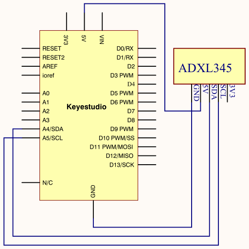
Connection for V4.0
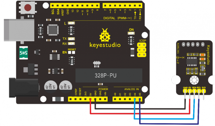
Connection for MEGA 2560 R3
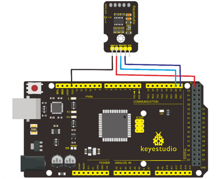
5.Sample Code
/*
keyestudio super learning kit
Project 25
ADXL345
http//www.keyestudio.com
*/
#include <Wire.h>
// Registers for ADXL345
#define ADXL345_ADDRESS (0xA6 >> 1)  // address for device is 8 bit but shift to the
                                     // right by 1 bit to make it 7 bit because the
                                     // wire library only takes in 7 bit addresses
#define ADXL345_REGISTER_XLSB (0x32)

int accelerometer_data[3];
// void because this only tells the cip to send data to its output register
// writes data to the slave's buffer
void i2c_write(int address, byte reg, byte data) {
  // Send output register address
  Wire.beginTransmission(address);
  // Connect to device
  Wire.write(reg);
  // Send data
  Wire.write(data); //low byte
  Wire.endTransmission();
}

// void because using pointers
// microcontroller reads data from the sensor's input register
void i2c_read(int address, byte reg, int count, byte* data) {
  // Used to read the number of data received
  int i = 0;
  // Send input register address
  Wire.beginTransmission(address);
  // Connect to device
  Wire.write(reg);
  Wire.endTransmission();

  // Connect to device
  Wire.beginTransmission(address);
  // Request data from slave
  // Count stands for number of bytes to request
  Wire.requestFrom(address, count);
  while(Wire.available()) // slave may send less than requested
  {
    char c = Wire.read(); // receive a byte as character
    data[i] = c;
    i++;
  }
  Wire.endTransmission();
}

void init_adxl345() {
  byte data = 0;

  i2c_write(ADXL345_ADDRESS, 0x31, 0x0B);   // 13-bit mode  +_ 16g
  i2c_write(ADXL345_ADDRESS, 0x2D, 0x08);   // Power register

  i2c_write(ADXL345_ADDRESS, 0x1E, 0x00);   // x
  i2c_write(ADXL345_ADDRESS, 0x1F, 0x00);   // Y
  i2c_write(ADXL345_ADDRESS, 0x20, 0x05);   // Z

  // Check to see if it worked!
  i2c_read(ADXL345_ADDRESS, 0X00, 1, &data);
  if(data==0xE5)
    Serial.println("it work Success");
  else
    Serial.println("it work Fail");
}

void read_adxl345() {
  byte bytes[6];
  memset(bytes,0,6);

  // Read 6 bytes from the ADXL345
  i2c_read(ADXL345_ADDRESS, ADXL345_REGISTER_XLSB, 6, bytes);
  // Unpack data
  for (int i=0;i<3;++i) {
    accelerometer_data[i] = (int)bytes[2*i] + (((int)bytes[2*i + 1]) << 8);
  }
}
// initialise and start everything
void setup() {
  Wire.begin();
  Serial.begin(9600);
  for(int i=0; i<3; ++i) {
    accelerometer_data[i]  = 0;
  }
  init_adxl345();
}


void loop() {
  read_adxl345();
  Serial.print("ACCEL ");
  Serial.print(float(accelerometer_data[0])*3.9/1000);//3.9mg/LSB scale factor in 13-bit mode
  Serial.print("t");
  Serial.print(float(accelerometer_data[1])*3.9/1000);
  Serial.print("t");
  Serial.print(float(accelerometer_data[2])*3.9/1000);
  Serial.print("n");
  delay(100);
}
//////////////////////////////////////////////////////////////////
6.Test Result
Wiring as the above diagram and power on, then upload the code and open the serial monitor, it will display the triaxial acceleration of sensor and its status, as the graph shown below.
Project 26: HC-SR04 Ultrasonic Sensor
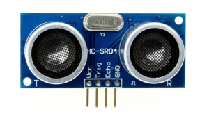
1.Introduction
The HC-SR04 Ultrasonic Sensor is a very affordable proximity/distance sensor that is mainly used for object avoidance in various robotics projects.
It essentially gives your Arduino eyes / spacial awareness and can prevent your robot from crashing or falling off a table. It has also been used in turret applications, water level sensing, and even as a parking sensor.
This simple project will use the HC-SR04 sensor with an Arduino and a Processing sketch to provide a more interactive display on your computer screen.
2.Hardware Required
- V4.0 Board or MEGA 2650 Board*1
- Ultrasonic Sensor*1
- Jumper Wire *1
- USB cable*1
3.Specification
•Working Voltage DC 5V
•Working Current 15mA
•Working Frequency 40KHz
•Max Range 4m
•Min Range 2cm
•Measuring Angle 15 degree
•Trigger Input Signal 10µS TTL pulse
•Echo Output Signal Input TTL lever signal and the range in proportion
4.Circuit Connection
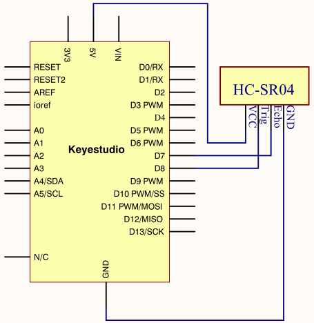
Connection for V4.0
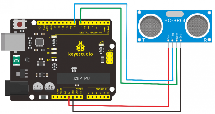
Connection for MEGA 2560 R3
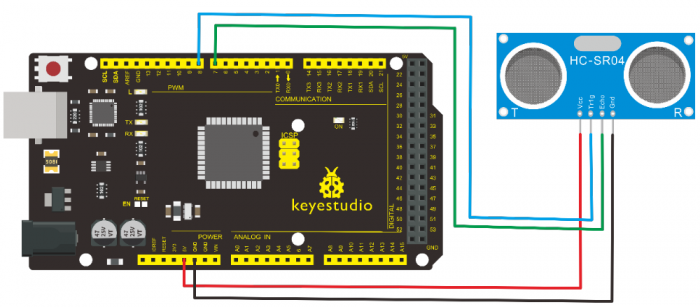
5.Sample Code
/*
 keyestudio super learning kit
 Project 26
 Ultrasonic
 http//www.keyestudio.com
*/
#define echoPin 7 // Echo Pin
#define trigPin 8 // Trigger Pin
#define LEDPin 13 // Onboard LED
int maximumRange = 200; // Maximum range needed
int minimumRange = 0; // Minimum range needed
long duration, distance; // Duration used to calculate distance
void setup() {
 Serial.begin (9600);
 pinMode(trigPin, OUTPUT);
 pinMode(echoPin, INPUT);
 pinMode(LEDPin, OUTPUT); // Use LED indicator (if required)
}
void loop() {
/* The following trigPin/echoPin cycle is used to determine the
 distance of the nearest object by bouncing soundwaves off of it. */
 digitalWrite(trigPin, LOW);
 delayMicroseconds(2);
 digitalWrite(trigPin, HIGH);
 delayMicroseconds(10);
 digitalWrite(trigPin, LOW);
 duration = pulseIn(echoPin, HIGH);
 //Calculate the distance (in cm) based on the speed of sound.
 distance = duration/58.2;

 if (distance >= maximumRange || distance <= minimumRange){
 /* Send a negative number to computer and Turn LED ON
 to indicate "out of range" */
 Serial.println("-1");
 digitalWrite(LEDPin, HIGH);
 }
 else {
 /* Send the distance to the computer using Serial protocol, and
 turn LED OFF to indicate successful reading. */
 Serial.println(distance);
 digitalWrite(LEDPin, LOW);
 }
 //Delay 50ms before next reading.
 delay(50);
}
//////////////////////////////////////////////////////////
6.Test Result
After upload well the code to V4.0 board, then open the serial monitor.
When place an object in front of the ultrasonic sensor (from near and far), it will detect the distance of object. The value will be displayed on the monitor.
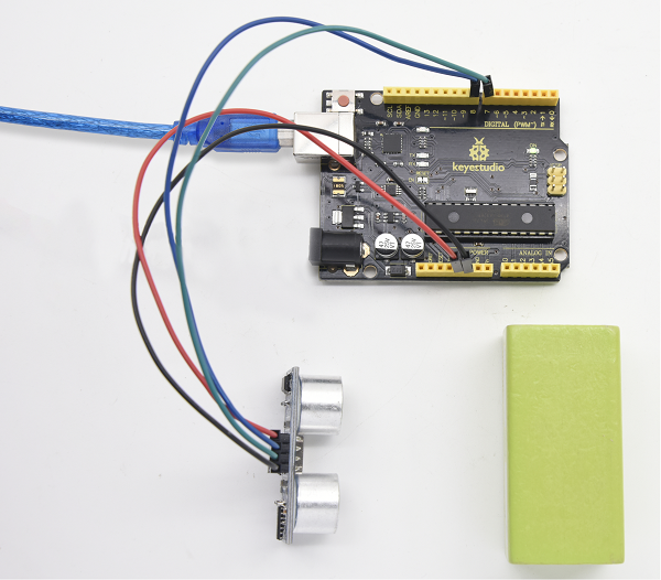
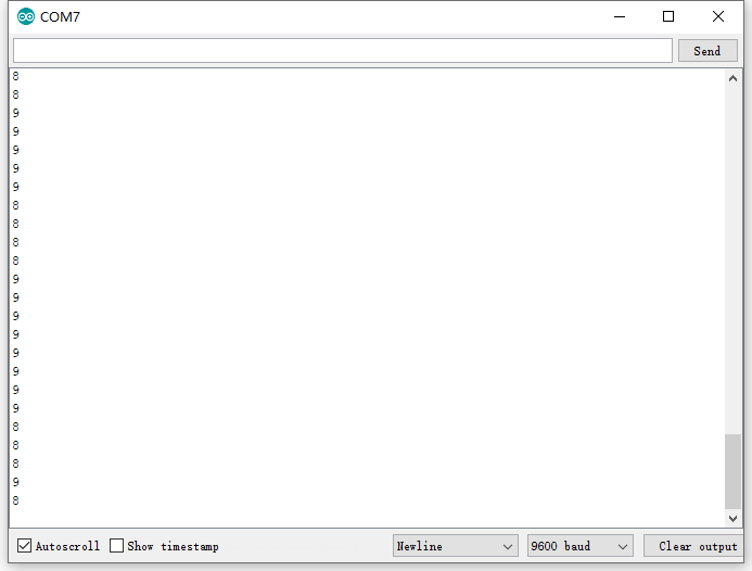
Project 27: Joystick Module
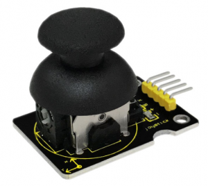
1.Introduction
Lots of robot projects need joystick. This module provides an affordable solution. By simply connecting to two analog inputs, the robot is at your commands with X, Y control. It also has a switch that is connected to a digital pin.
This joystick module can be easily connected to Arduino by IO Shield. This module is for Arduino(V5) with cable supplied.
2.Hardware Required
- V4.0 Board or MEGA 2650 Board*1
- Joystick Module*1
- USB cable*1
3.Specification
•Supply Voltage 3.3V to 5V
•Interface Analog x2, Digital x1
4.Circuit Connection
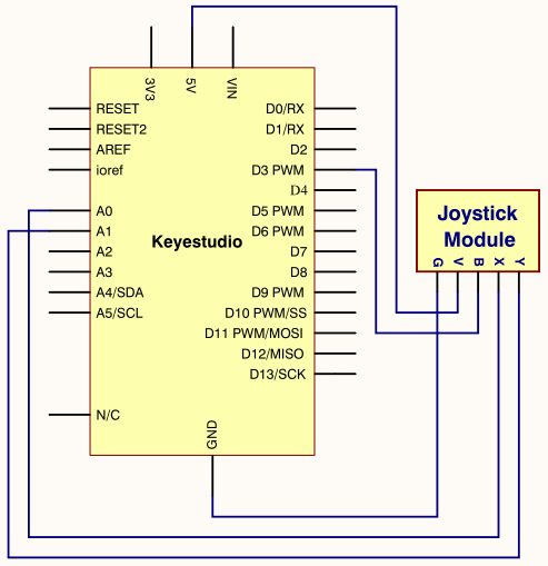
Connection for V4.0
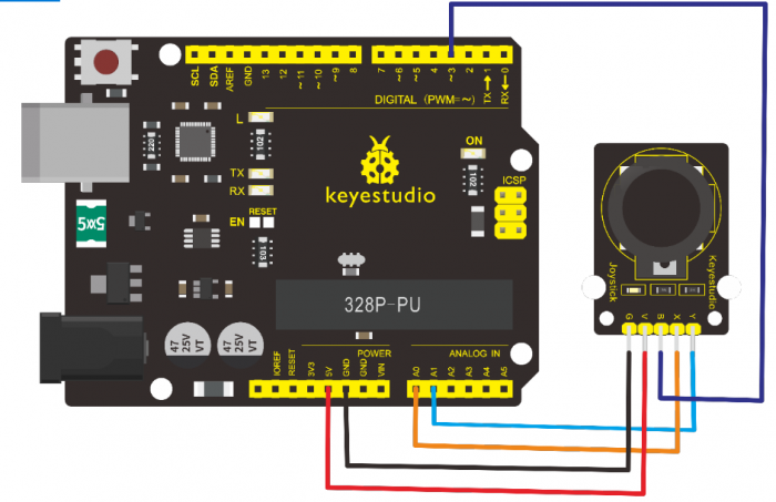
Connection for MEGA 2560 R3
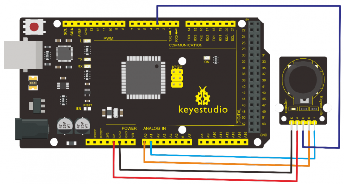
5.Sample Code
/*
 keyestudio super learning kit
 Project 27
 joystick
 http//www.keyestudio.com
*/
int JoyStick_X = 0; //x
int JoyStick_Y = 1; //y
int JoyStick_Z = 3; //key
  void setup()
{
  pinMode(JoyStick_Z, INPUT);
  Serial.begin(9600); // 9600 bps
}
void loop()
{
  int x,y,z;
  x=analogRead(JoyStick_X);
  y=analogRead(JoyStick_Y);
  z=digitalRead(JoyStick_Z);
  Serial.print(x ,DEC);
  Serial.print(",");
  Serial.print(y ,DEC);
  Serial.print(",");
  Serial.println(z ,DEC);
  delay(100);
}
//////////////////////////////////////////////////////////
6.Test Result
Wiring well and uploading the code, open the serial monitor and set the baud rate to 9600, push the joystick, you will see the value shown below.
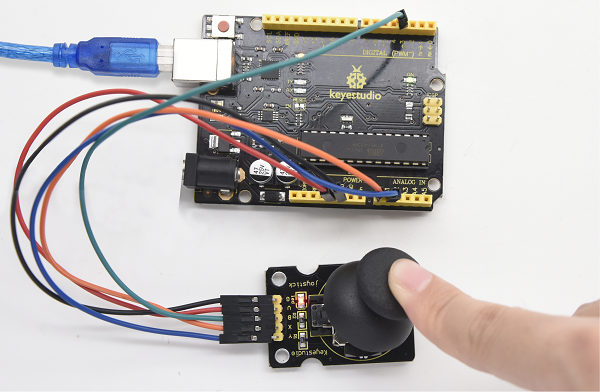
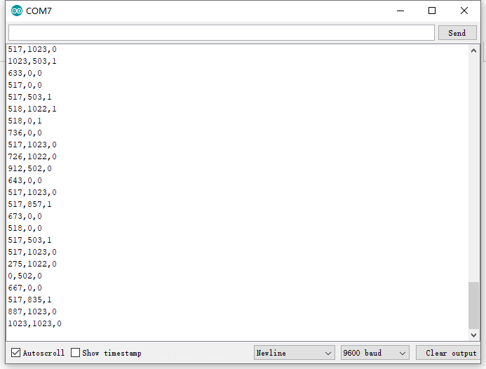
Project 28: 5V Relay Module
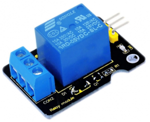
1.Introduction
This single relay module can be used in interactive projects. This module uses SONGLE 5v high-quality relay.
It can also be used to control the lighting, electrical and other equipment. The modular design makes it easy to expand with the Arduino Board (not included).
The Relay output is by a light-emitting diode. It can be controlled through digital IO port, such as solenoid valves, lamps, motors and other high current or high voltage devices.
2.Hardware Required
- V4.0 Board or MEGA 2650 Board*1
- Relay Module*1
- Jumper Wire *1
- USB cable*1
3.Specification
•Type Digital
•Rated Current 10A (NO) 5A (NC)
•Maximum Switching Voltage 150VAC 24VDC
•Digital Interface
•Control Signal TTL level
•Rated Load 8A 150VAC (NO) 10A 24VDC (NO), 5A 250VAC (NO/NC) 5A 24VDC (NO/NC)
•Maximum Switching Power AC1200VA DC240W (NO) AC625VA DC120W (NC)
•Contact Action Time 10ms
4.Circuit Connection
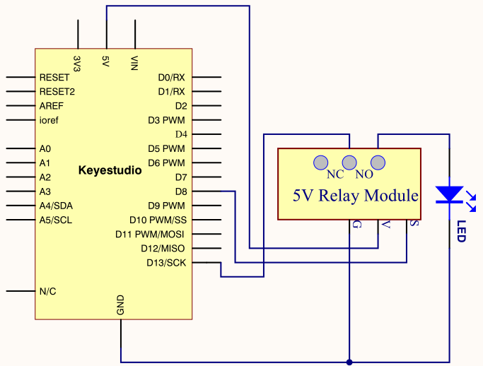
Connection for V4.0
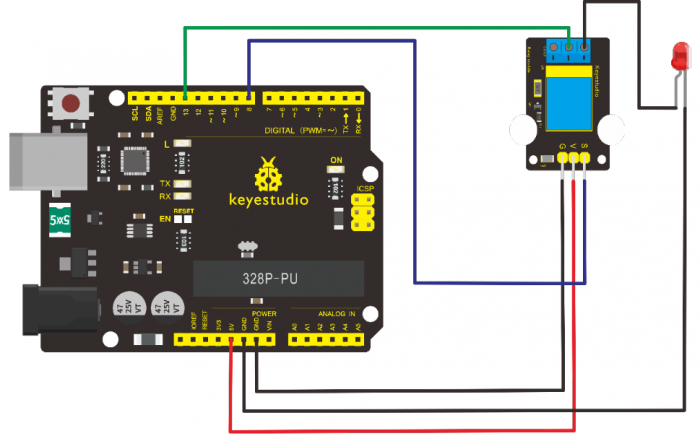
Connection for MEGA 2560 R3
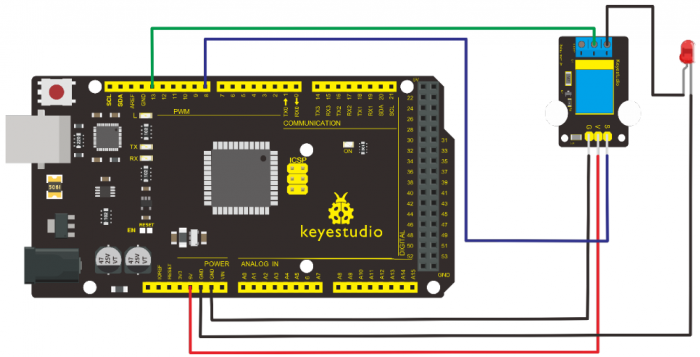
5.Sample Code
/*
 keyestudio super learning kit
 Project 28
 Relay
 http//www.keyestudio.com
*/
 int Relay = 8;
  void setup()
{
  pinMode(13, OUTPUT);         //Set Pin13 as output
  digitalWrite(13, HIGH);     //Set Pin13 High
  pinMode(Relay, OUTPUT);     //Set Pin8 as output
}
void loop()
{
          digitalWrite(Relay, HIGH);   //Turn off relay
          delay(2000);
          digitalWrite(Relay, LOW);    //Turn on relay
          delay(2000);
}
//////////////////////////////////////////////////////////
6.Test Result
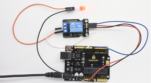
Project 29: DS3231 Clock Module
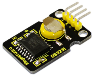
1.Introduction
DS3231 is equipped with integrated TCXO and crystal, which makes it a cost-effective I2C real time clock with high precision.
The device carries a battery input, so even if you disconnect the main power supply, it can still maintain accurate timing. The integrated oscillator ensures the long-term accuracy of the device and reduces the number of components.
DS3231 provides both commercial and industrial temperature range and supports 16 pins small-outline package (300mil).
The module itself can adapt to the system of 3.3V and 5V without level switch, which is quite convenient!
2.Hardware Required
- V4.0 Board or MEGA 2650 Board*1
- DS3231 Clock Module*1
- Jumper Wire *1
- USB cable*1
3.Specification
•Temperature Range -40 to +85;
•Timing Accuracy ± 5ppm (±0.432 seconds / day)
•Provide battery backup for continuous timing
•Low power consumption
•Device package and function compatible with DS3231
•Complete clock calendar function contains seconds and minutes, hour, week, date, month, and year timing and provides leap year compensation until 2100.
•Two calendar clock
•Output 1Hz and 32.768kHz
•Reset output and Input Debounce of Pushbutton
•High speed (400kHz), I2C serial bus
•Supply voltage +3.3V to +5.5V
•Digital temperature sensor with a precision of±3℃
•Working temperature -40 ~ C to +85 ~ C
•16 pins Small Outline Package (300mil)
4.Circuit Connection
This module adopts the IIC test method, so only need to connect ‘SDA’ to Arduino A4, ‘SCL’ to A5, ‘+’ to VCC and ‘-’ to GND as follows
Connection for V4.0
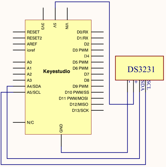
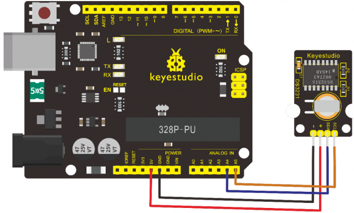
Connection for MEGA 2560 R3
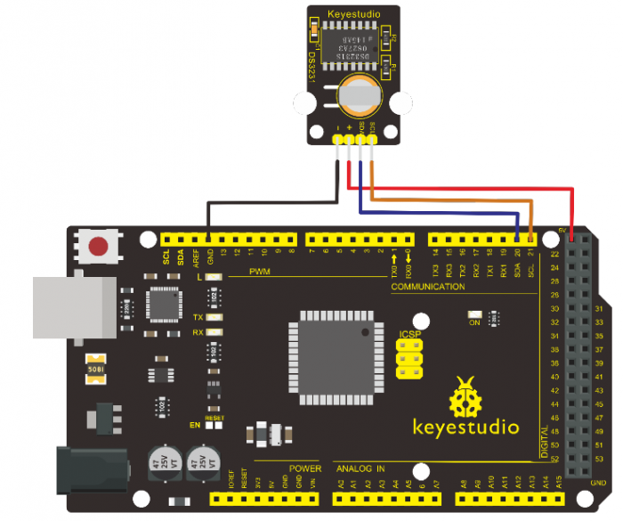
5.Sample Code
Before compiling the code, you’d better put DS3231 library under file into Arduino catalogue.
/*
 keyestudio super learning kit
 Project 29
 clock
 http//www.keyestudio.com
*/
#include <Wire.h>
#include "DS3231.h"
DS3231 RTC; //Create the DS3231 object
char weekDay[][4] = {"Sun", "Mon", "Tue", "Wed", "Thu", "Fri", "Sat" };
//year, month, date, hour, min, sec and week-day(starts from 0 and goes to 6)
//writing any non-existent time-data may interfere with normal operation of the RTC.
//Take care of week-day also.
DateTime dt(2011, 11, 10, 15, 18, 0, 5);//open the series port and you can check time here or make a change to the time as needed.
void setup ()
{   Serial.begin(57600);//set baud rate to 57600
    Wire.begin();
    RTC.begin();
    RTC.adjust(dt); //Adjust date-time as defined 'dt' above
}
void loop ()
{
 DateTime now = RTC.now(); //get the current date-time
    Serial.print(now.year(), DEC);
    Serial.print("/");
    Serial.print(now.month(), DEC);
    Serial.print("/");
    Serial.print(now.date(), DEC);
    Serial.print(" ");
    Serial.print(now.hour(), DEC);
    Serial.print(":");
    Serial.print(now.minute(), DEC);
    Serial.print(":");
    Serial.print(now.second(), DEC);
    Serial.println();
    Serial.print(weekDay[now.dayOfWeek()]);
    Serial.println();
    delay(1000);
}
//////////////////////////////////////////////////////////
6.Test Result
Done uploading the code to arduino, open the serial monitor and get the following results
Project 30: DHT11 Temperature and Humidity Sensor
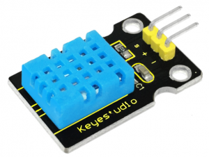
1.Introduction
This DHT11 Temperature and Humidity Sensor features calibrated digital signal output with the temperature and humidity sensor complex. Its technology ensures high reliability and excellent long-term stability. A high-performance 8-bit microcontroller is connected.
This sensor includes a resistive element and a sense of wet NTC temperature measuring devices. It has the advantages of excellent quality, fast response, anti-interference ability and high cost performance.
Each DHT11 sensor features extremely accurate calibration data of humidity calibration chamber. The calibration coefficients stored in the OTP program memory, internal sensors detect signals in the process, and we should call these calibration coefficients.
The single-wire serial interface system is integrated to make it quick and easy. Qualities of small size, low power, and 20-meter signal transmission distance make it a widely applied application and even the most demanding one. Convenient connection and special package can be provided according to your need.
2.Hardware Required
- V4.0 Board or MEGA 2650 Board*1
- DHT11 sensor*1
- Jumper Wire *1
- USB cable*1
3.Specification
•Supply Voltage +5 V
•Temperature Range 0-50 °C error of ± 2 °C
•Humidity 20-90% RH ± 5% RH error
•Interface digital
4.Circuit Connection
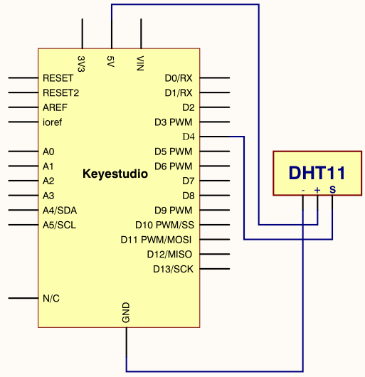
Connection for V4.0
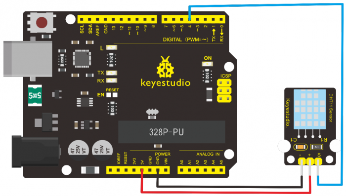
Connection for MEGA 2560 R3
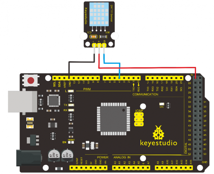
5.Sample Code
Please download the DHT11Lib firstly. Or see the website
/*
 keyestudio super learning kit
 Project 30
 DHT11
 http//www.keyestudio.com
*/
#include <dht11.h>
dht11 DHT;
#define DHT11_PIN 4

void setup(){
  Serial.begin(9600);
  Serial.println("DHT TEST PROGRAM ");
  Serial.print("LIBRARY VERSION: ");
  Serial.println(DHT11LIB_VERSION);
  Serial.println();
  Serial.println("Type,tstatus,tHumidity (%),tTemperature (C)");
}

void loop(){
  int chk;
  Serial.print("DHT11, t");
  chk = DHT.read(DHT11_PIN);    // READ DATA
  switch (chk){
    case DHTLIB_OK:
                Serial.print("OK,t");
                break;
    case DHTLIB_ERROR_CHECKSUM:
                Serial.print("Checksum error,t");
                break;
    case DHTLIB_ERROR_TIMEOUT:
                Serial.print("Time out error,t");
                break;
    default:
                Serial.print("Unknown error,t");
                break;
  }
 // DISPLAT DATA
  Serial.print(DHT.humidity,1);
  Serial.print(",t");
  Serial.println(DHT.temperature,1);

  delay(1000);
}
//////////////////////////////////////////////////////////
6.Test Result
Wire it up well and upload the above code to V4.0 board.
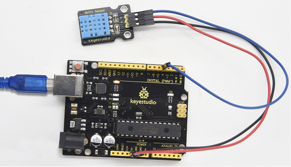
Then open the serial monitor and set the baud rate to 9600, you will see the current temperature and humidity value.
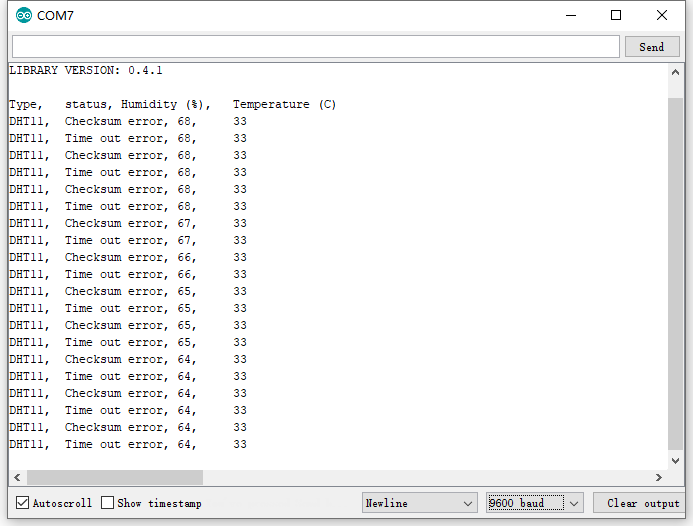
Project 31: Soil Humidity Sensor
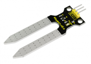
1.Introduction
This is a simple soil humidity sensor aims to detect the soil humidity. If the soil is lack of water, the analog value output by the sensor will decrease; otherwise, it will increase.
If you use this sensor to make an automatic watering device, it can detect whether your botany is thirsty so as to prevent it from withering when you go out. Using the sensor with Arduino controller makes your plant more comfortable and your garden smarter.
The soil humidity sensor module is not as complicated as you might think, and if you need to detect the soil in your project, it will be your best choice.
The sensor is set with two probes inserted into the soil, then with the current go through the soil, the sensor will get resistance value by reading the current changes between the two probes and convert such resistance value into moisture content.
The higher the moisture (less resistance) is, the higher conductivity the soil has.
The surface of the sensor have undergone metallization process to prolong its service life. Insert it into the soil and then use the AD converter to read it. With the help of this sensor, the plant can remind of you I need water.
2.Hardware Required
- V4.0 Board or MEGA 2650 Board*1
- Soil Humidity Sensor*1
- Jumper Wire *1
- USB cable*1
3.Specification
•Power Supply Voltage 3.3V or 5V
•Working Current ≤ 20mA
•Output Voltage 0-2.3V (When the sensor is totally immersed in water, the voltage will be 2.3V)
•5V power supply (the higher humidity, the higher the output voltage)
•Sensor Type Analog output
•Interface Definition Pin1- signal, pin2- GND, pin3 — VCC
4.Circuit Connection
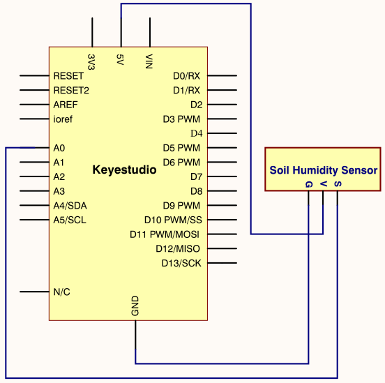
Connection for V4.0
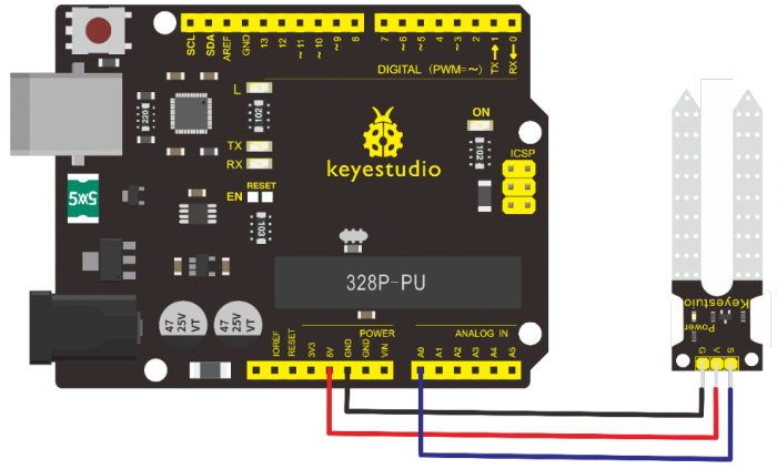
Connection for MEGA 2560 R3
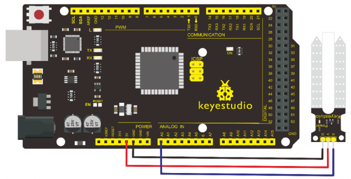
5.Sample Code
/*
keyestudio super learning kit
Project 31
soil humidity sensor
http//www.keyestudio.com
*/
 void setup(){
 Serial.begin(57600);
 }
 void loop(){
  Serial.print("Moisture Sensor Value");
  Serial.println(analogRead(0));
  delay(100);
}
//////////////////////////////////////////////////////////
6.Test Result
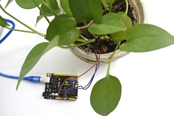
Project 32: RC522 RFID Module
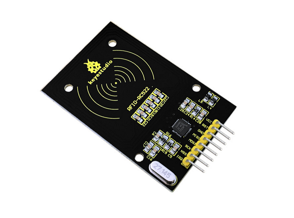
1.Introduction
MF522-AN module adopts Philips MFRC522 original reader circuit chip design, easy to use, low cost, suitable for equipment development, development of advanced applications, the need for the user of RF card terminal design / production. It can be loaded directly into a variety of readers molds.
Module uses voltage of 3.3V, through the SPI interface using simple few lines, it can be directly connected to any CPU board communication modules to guarantee stable and reliable work and reader distance.
2.Hardware Required
- V4.0 Board or MEGA 2650 Board*1
- RFID Module*1
- Jumper Wire *1
- USB cable*1
3.Specification
1.Current 13-26mA / DC 3.3V
2.Idle Current 10-13mA / DC 3.3V
3.Sleep Current <80uA
4.Peak Current <30mA
5.Operating Frequency 13.56MHz
6.Supported card types mifare1 S50, mifare1 S70, mifare UltraLight, mifare Pro, mifare Desfire
7.Environmental Operating Temperature -20-80 degrees Celsius
8.Environment Storage Temperature -40-85 degrees Celsius
9.Relative Humidity 5% -95%
4.Circuit Connection
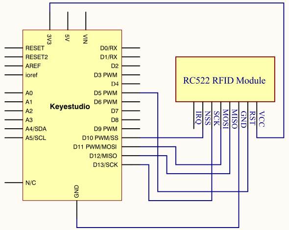
Connection for V4.0
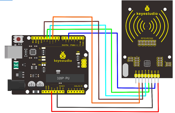
Connection for 2560 R3
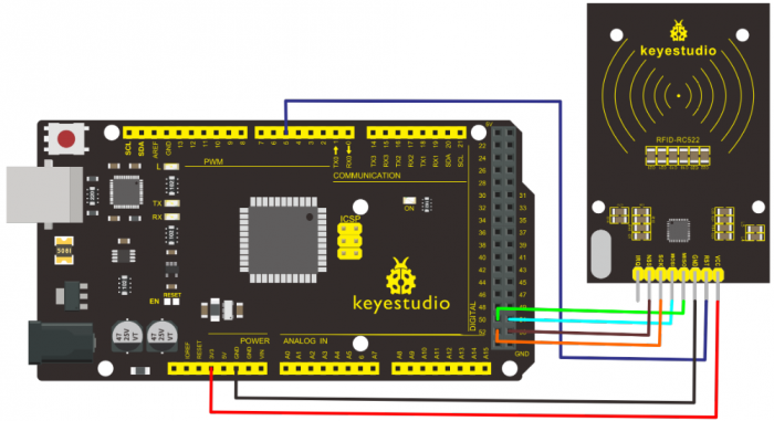
5.Sample Code
/*
 keyestudio super learning kit
 Project 32
 RFID
 http//www.keyestudio.com
*/
#include <SPI.h>
#define  uchar unsigned char
#define uint  unsigned int
#define MAX_LEN 16
const int chipSelectPin = 10;//if the controller is UNO,328,168
const int NRSTPD = 5;

//MF522command word
#define PCD_IDLE              0x00               //NO action;concel current command
#define PCD_AUTHENT           0x0E               //verify key
#define PCD_RECEIVE           0x08               //receive data
#define PCD_TRANSMIT          0x04               //send data
#define PCD_TRANSCEIVE        0x0C               //receive and send data
#define PCD_RESETPHASE        0x0F               //reset
#define PCD_CALCCRC           0x03               //CRC calculation

//Mifare_One Card command word
#define PICC_REQIDL           0x26               // line-tracking area is dormant #define PICC_REQALL           0x52                     //line-tracking area is interfered
#define PICC_ANTICOLL         0x93               //Anti collision
#define PICC_SElECTTAG        0x93               //choose cards
#define PICC_AUTHENT1A        0x60               //Verify A key
#define PICC_AUTHENT1B        0x61               //Verify B key
#define PICC_READ             0x30               // Reader Module
#define PICC_WRITE            0xA0               // letter block
#define PICC_DECREMENT        0xC0
#define PICC_INCREMENT        0xC1
#define PICC_RESTORE          0xC2               //Transfer data to buffer
#define PICC_TRANSFER         0xB0               //Save buffer data
#define PICC_HALT             0x50               //Dormancy


//MF522 Error code returned when communication
#define MI_OK                 0
#define MI_NOTAGERR           1
#define MI_ERR                2


//------------------MFRC522 Register---------------
//Page 0:Command and Status
#define     Reserved00            0x00
#define     CommandReg            0x01
#define     CommIEnReg            0x02
#define     DivlEnReg             0x03
#define     CommIrqReg            0x04
#define     DivIrqReg             0x05
#define     ErrorReg              0x06
#define     Status1Reg            0x07
#define     Status2Reg            0x08
#define     FIFODataReg           0x09
#define     FIFOLevelReg          0x0A
#define     WaterLevelReg         0x0B
#define     ControlReg            0x0C
#define     BitFramingReg         0x0D
#define     CollReg               0x0E
#define     Reserved01            0x0F
//Page 1:Command
#define     Reserved10            0x10
#define     ModeReg               0x11
#define     TxModeReg             0x12
#define     RxModeReg             0x13
#define     TxControlReg          0x14
#define     TxAutoReg             0x15
#define     TxSelReg              0x16
#define     RxSelReg              0x17
#define     RxThresholdReg        0x18
#define     DemodReg              0x19
#define     Reserved11            0x1A
#define     Reserved12            0x1B
#define     MifareReg             0x1C
#define     Reserved13            0x1D
#define     Reserved14            0x1E
#define     SerialSpeedReg        0x1F
//Page 2:CFG
#define     Reserved20            0x20
#define     CRCResultRegM         0x21
#define     CRCResultRegL         0x22
#define     Reserved21            0x23
#define     ModWidthReg           0x24
#define     Reserved22            0x25
#define     RFCfgReg              0x26
#define     GsNReg                0x27
#define     CWGsPReg            0x28
#define     ModGsPReg             0x29
#define     TModeReg              0x2A
#define     TPrescalerReg         0x2B
#define     TReloadRegH           0x2C
#define     TReloadRegL           0x2D
#define     TCounterValueRegH     0x2E
#define     TCounterValueRegL     0x2F
//Page 3:TestRegister
#define     Reserved30            0x30
#define     TestSel1Reg           0x31
#define     TestSel2Reg           0x32
#define     TestPinEnReg          0x33
#define     TestPinValueReg       0x34
#define     TestBusReg            0x35
#define     AutoTestReg           0x36
#define     VersionReg            0x37
#define     AnalogTestReg         0x38
#define     TestDAC1Reg           0x39
#define     TestDAC2Reg           0x3A
#define     TestADCReg            0x3B
#define     Reserved31            0x3C
#define     Reserved32            0x3D
#define     Reserved33            0x3E
#define     Reserved34        0x3F
uchar serNum[5];
uchar  writeDate[16] ={'T', 'e', 'n', 'g', ' ', 'B', 'o', 0, 0, 0, 0, 0, 0, 0, 0,0};
uchar sectorKeyA[16][16] = {{0xFF, 0xFF, 0xFF, 0xFF, 0xFF, 0xFF},
                             {0xFF, 0xFF, 0xFF, 0xFF, 0xFF, 0xFF},
                             {0xFF, 0xFF, 0xFF, 0xFF, 0xFF, 0xFF},
                            };
 uchar sectorNewKeyA[16][16] = {{0xFF, 0xFF, 0xFF, 0xFF, 0xFF, 0xFF},
                                {0xFF, 0xFF, 0xFF, 0xFF, 0xFF, 0xFF, 0xff,0x07,0x80,0x69, 0xFF, 0xFF, 0xFF, 0xFF, 0xFF, 0xFF},
                                {0xFF, 0xFF, 0xFF, 0xFF, 0xFF, 0xFF, 0xff,0x07,0x80,0x69, 0xFF, 0xFF, 0xFF, 0xFF, 0xFF, 0xFF},
                               };

void setup() {
   Serial.begin(9600);                       // RFID reader SOUT pin connected to Serial RX pin at 2400bps
 // start the SPI library:
  SPI.begin();

  pinMode(chipSelectPin,OUTPUT);             // Set digital pin 10 as OUTPUT to connect it to the RFID /ENABLE pin
    digitalWrite(chipSelectPin, LOW);          // Activate the RFID reader
  pinMode(NRSTPD,OUTPUT);               // Set digital pin 10 , Not Reset and Power-down
    digitalWrite(NRSTPD, HIGH);

  MFRC522_Init();
}

void loop()
{
    uchar i,tmp;
  uchar status;
        uchar str[MAX_LEN];
        uchar RC_size;
        uchar blockAddr;  //Select the address of the operation 0~63


    // searching card, return card type
    status = MFRC522_Request(PICC_REQIDL, str);
    if (status == MI_OK)
    {
    }


    status = MFRC522_Anticoll(str);
    memcpy(serNum, str, 5);
    if (status == MI_OK)
    {
                        Serial.println("The card's number is  : ");
      Serial.print(serNum[0],BIN);
      Serial.print(serNum[1],BIN);
      Serial.print(serNum[2],BIN);
      Serial.print(serNum[3],BIN);
      Serial.print(serNum[4],BIN);
                        Serial.println(" ");
    }

    // select card, return card capacity
    RC_size = MFRC522_SelectTag(serNum);
    if (RC_size != 0)
    {}

    // write data card
    blockAddr = 7;    // data block 7
    status = MFRC522_Auth(PICC_AUTHENT1A, blockAddr, sectorKeyA[blockAddr/4], serNum);  // authentication
    if (status == MI_OK)
    {
      // write data
      status = MFRC522_Write(blockAddr, sectorNewKeyA[blockAddr/4]);
                        Serial.print("set the new card password, and can modify the data of the Sector: ");
                        Serial.print(blockAddr/4,DEC);

                        // write data
                        blockAddr = blockAddr - 3 ;
                        status = MFRC522_Write(blockAddr, writeDate);
                        if(status == MI_OK)
                        {
                           Serial.println("OK!");
                        }
    }

    // read card
    blockAddr = 7;    // data block 7
    status = MFRC522_Auth(PICC_AUTHENT1A, blockAddr, sectorNewKeyA[blockAddr/4], serNum); // authentication
    if (status == MI_OK)
    {
      // read data
                        blockAddr = blockAddr - 3 ;
                        status = MFRC522_Read(blockAddr, str);
      if (status == MI_OK)
      {
                                Serial.println("Read from the card ,the data is : ");
        for (i=0; i<16; i++)
        {
                          Serial.print(str[i]);
        }
                                Serial.println(" ");
      }
    }
                Serial.println(" ");
    MFRC522_Halt();     // command card to enter standby mode

}

void Write_MFRC522(uchar addr, uchar val)
{
  digitalWrite(chipSelectPin, LOW);

  SPI.transfer((addr<<1)&0x7E);
  SPI.transfer(val);

  digitalWrite(chipSelectPin, HIGH);
}


uchar Read_MFRC522(uchar addr)
{
  uchar val;

  digitalWrite(chipSelectPin, LOW);

  // address format: 1XXXXXX0
  SPI.transfer(((addr<<1)&0x7E) | 0x80);
  val =SPI.transfer(0x00);

  digitalWrite(chipSelectPin, HIGH);

  return val;
}


void SetBitMask(uchar reg, uchar mask)
{
    uchar tmp;
    tmp = Read_MFRC522(reg);
    Write_MFRC522(reg, tmp | mask);  // set bit mask
}


void ClearBitMask(uchar reg, uchar mask)
{
    uchar tmp;
    tmp = Read_MFRC522(reg);
    Write_MFRC522(reg, tmp & (~mask));  // clear bit mask
}


void AntennaOn(void)
{
  uchar temp;

  temp = Read_MFRC522(TxControlReg);
  if (!(temp & 0x03))
  {
    SetBitMask(TxControlReg, 0x03);
  }
}

void AntennaOff(void)
{
  ClearBitMask(TxControlReg, 0x03);
}

void MFRC522_Reset(void)
{
    Write_MFRC522(CommandReg, PCD_RESETPHASE);
}

void MFRC522_Init(void)
{
  digitalWrite(NRSTPD,HIGH);

  MFRC522_Reset();

  //Timer: TPrescaler*TreloadVal/6.78MHz = 24ms
    Write_MFRC522(TModeReg, 0x8D);    //Tauto=1; f(Timer) = 6.78MHz/TPreScaler
    Write_MFRC522(TPrescalerReg, 0x3E); //TModeReg[3..0] + TPrescalerReg
    Write_MFRC522(TReloadRegL, 30);
    Write_MFRC522(TReloadRegH, 0);

  Write_MFRC522(TxAutoReg, 0x40);   //100%ASK
  Write_MFRC522(ModeReg, 0x3D);   //CRC initial value


  AntennaOn();    // open antenna
}
uchar MFRC522_Request(uchar reqMode, uchar *TagType)
{
  uchar status;
  uint backBits;      // received data bits

  Write_MFRC522(BitFramingReg, 0x07);   //TxLastBists = BitFramingReg[2..0] ???

  TagType[0] = reqMode;
  status = MFRC522_ToCard(PCD_TRANSCEIVE, TagType, 1, TagType, &backBits);

  if ((status != MI_OK) || (backBits != 0x10))
  {
    status = MI_ERR;
  }

  return status;
}

uchar MFRC522_ToCard(uchar command, uchar *sendData, uchar sendLen, uchar *backData, uint *backLen)
{
    uchar status = MI_ERR;
    uchar irqEn = 0x00;
    uchar waitIRq = 0x00;
    uchar lastBits;
    uchar n;
    uint i;

    switch (command)
    {
        case PCD_AUTHENT:   // card key authentication
    {
      irqEn = 0x12;
      waitIRq = 0x10;
      break;
    }
    case PCD_TRANSCEIVE:  // send data in FIFO
    {
      irqEn = 0x77;
      waitIRq = 0x30;
      break;
    }
    default:
      break;
    }

    Write_MFRC522(CommIEnReg, irqEn|0x80);  // Allow interrupt request
    ClearBitMask(CommIrqReg, 0x80);     // clear bits of all interrupt request
    SetBitMask(FIFOLevelReg, 0x80);     //FlushBuffer=1, FIFO initialization


  Write_MFRC522(CommandReg, PCD_IDLE);  //NO action; cancel current command ???

  // write data into FIFO
    for (i=0; i<sendLen; i++)
    {
    Write_MFRC522(FIFODataReg, sendData[i]);
  }

  // execute command
  Write_MFRC522(CommandReg, command);
    if (command == PCD_TRANSCEIVE)
    {
    SetBitMask(BitFramingReg, 0x80);    //StartSend=1,transmission of data starts
  }

  // wait for the completion of data receiving
  i = 2000; // adjust i according to clock frequency, maximum waiting time of operating M1 is 25ms  ???
    do
    {
    //CommIrqReg[7..0]
    //Set1 TxIRq RxIRq IdleIRq HiAlerIRq LoAlertIRq ErrIRq TimerIRq
        n = Read_MFRC522(CommIrqReg);
        i--;
    }
    while ((i!=0) && !(n&0x01) && !(n&waitIRq));

    ClearBitMask(BitFramingReg, 0x80);      //StartSend=0

    if (i != 0)
    {
        if(!(Read_MFRC522(ErrorReg) & 0x1B))  //BufferOvfl Collerr CRCErr ProtecolErr
        {
            status = MI_OK;
            if (n & irqEn & 0x01)
            {
        status = MI_NOTAGERR;     //??
      }

            if (command == PCD_TRANSCEIVE)
            {
                n = Read_MFRC522(FIFOLevelReg);
                lastBits = Read_MFRC522(ControlReg) & 0x07;
                if (lastBits)
                {
          *backLen = (n-1)*8 + lastBits;
        }
                else
                {
          *backLen = n*8;
        }

                if (n == 0)
                {
          n = 1;
        }
                if (n > MAX_LEN)
                {
          n = MAX_LEN;
        }

        // read data which FIFO received
                for (i=0; i<n; i++)
                {
          backData[i] = Read_MFRC522(FIFODataReg);
        }
            }
        }
        else
        {
      status = MI_ERR;
    }

    }

    //SetBitMask(ControlReg,0x80);           //timer stops
    //Write_MFRC522(CommandReg, PCD_IDLE);

    return status;
}

uchar MFRC522_Anticoll(uchar *serNum)
{
    uchar status;
    uchar i;
  uchar serNumCheck=0;
    uint unLen;

  Write_MFRC522(BitFramingReg, 0x00);   //TxLastBists = BitFramingReg[2..0]

    serNum[0] = PICC_ANTICOLL;
    serNum[1] = 0x20;
    status = MFRC522_ToCard(PCD_TRANSCEIVE, serNum, 2, serNum, &unLen);

    if (status == MI_OK)
  {
    // verify card sequence number
    for (i=0; i<4; i++)
    {
      serNumCheck ^= serNum[i];
    }
    if (serNumCheck != serNum[i])
    {
      status = MI_ERR;
    }
    }

    //SetBitMask(CollReg, 0x80);    //ValuesAfterColl=1

    return status;
}

void CalulateCRC(uchar *pIndata, uchar len, uchar *pOutData)
{
    uchar i, n;

    ClearBitMask(DivIrqReg, 0x04);      //CRCIrq = 0
    SetBitMask(FIFOLevelReg, 0x80);     // clear FIFO pointer
    //Write_MFRC522(CommandReg, PCD_IDLE);

  // write data into FIFO
    for (i=0; i<len; i++)
    {
    Write_MFRC522(FIFODataReg, *(pIndata+i));
  }
    Write_MFRC522(CommandReg, PCD_CALCCRC);

  // wait for the completion of CRC calculation
    i = 0xFF;
    do
    {
        n = Read_MFRC522(DivIrqReg);
        i--;
    }
    while ((i!=0) && !(n&0x04));      //CRCIrq = 1

  // read CRC calculation result
    pOutData[0] = Read_MFRC522(CRCResultRegL);
    pOutData[1] = Read_MFRC522(CRCResultRegM);
}

uchar MFRC522_SelectTag(uchar *serNum)
{
    uchar i;
  uchar status;
  uchar size;
    uint recvBits;
    uchar buffer[9];

  //ClearBitMask(Status2Reg, 0x08);     //MFCrypto1On=0

    buffer[0] = PICC_SElECTTAG;
    buffer[1] = 0x70;
    for (i=0; i<5; i++)
    {
      buffer[i+2] = *(serNum+i);
    }
  CalulateCRC(buffer, 7, &buffer[7]);   //??
    status = MFRC522_ToCard(PCD_TRANSCEIVE, buffer, 9, buffer, &recvBits);

    if ((status == MI_OK) && (recvBits == 0x18))
    {
    size = buffer[0];
  }
    else
    {
    size = 0;
  }

    return size;
}

uchar MFRC522_Auth(uchar authMode, uchar BlockAddr, uchar *Sectorkey, uchar *serNum)
{
    uchar status;
    uint recvBits;
    uchar i;
  uchar buff[12];

  // Verification commands + block address + sector password + card sequence number
    buff[0] = authMode;
    buff[1] = BlockAddr;
    for (i=0; i<6; i++)
    {
    buff[i+2] = *(Sectorkey+i);
  }
    for (i=0; i<4; i++)
    {
    buff[i+8] = *(serNum+i);
  }
    status = MFRC522_ToCard(PCD_AUTHENT, buff, 12, buff, &recvBits);

    if ((status != MI_OK) || (!(Read_MFRC522(Status2Reg) & 0x08)))
    {
    status = MI_ERR;
  }

    return status;
}

uchar MFRC522_Read(uchar blockAddr, uchar *recvData)
{
    uchar status;
    uint unLen;

    recvData[0] = PICC_READ;
    recvData[1] = blockAddr;
    CalulateCRC(recvData,2, &recvData[2]);
    status = MFRC522_ToCard(PCD_TRANSCEIVE, recvData, 4, recvData, &unLen);

    if ((status != MI_OK) || (unLen != 0x90))
    {
        status = MI_ERR;
    }

    return status;
}

uchar MFRC522_Write(uchar blockAddr, uchar *writeData)
{
    uchar status;
    uint recvBits;
    uchar i;
  uchar buff[18];

    buff[0] = PICC_WRITE;
    buff[1] = blockAddr;
    CalulateCRC(buff, 2, &buff[2]);
    status = MFRC522_ToCard(PCD_TRANSCEIVE, buff, 4, buff, &recvBits);

    if ((status != MI_OK) || (recvBits != 4) || ((buff[0] & 0x0F) != 0x0A))
    {
    status = MI_ERR;
  }

    if (status == MI_OK)
    {
        for (i=0; i<16; i++)    // write 16Byte data into FIFO
        {
          buff[i] = *(writeData+i);
        }
        CalulateCRC(buff, 16, &buff[16]);
        status = MFRC522_ToCard(PCD_TRANSCEIVE, buff, 18, buff, &recvBits);

    if ((status != MI_OK) || (recvBits != 4) || ((buff[0] & 0x0F) != 0x0A))
        {
      status = MI_ERR;
    }
    }

    return status;
}

void MFRC522_Halt(void)
{
  uchar status;
    uint unLen;
    uchar buff[4];

    buff[0] = PICC_HALT;
    buff[1] = 0;
    CalulateCRC(buff, 2, &buff[2]);

    status = MFRC522_ToCard(PCD_TRANSCEIVE, buff, 4, buff,&unLen);
}
//////////////////////////////////////////////////////////
Note if you want to use MEGA 2560 R3, please in the code change
const int chipSelectPin = 10;//if the controller is V4.0
const int chipSelectPin = 53;//if the controller is MEGA2560
6.Test Result
In this experiment, when the IC card approaches, RFID module will write data to the IC card and read the card’s data, you can see the data on the monitor window. Shown below.
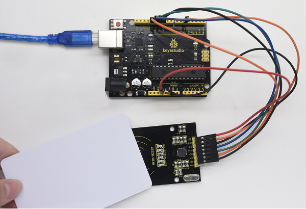
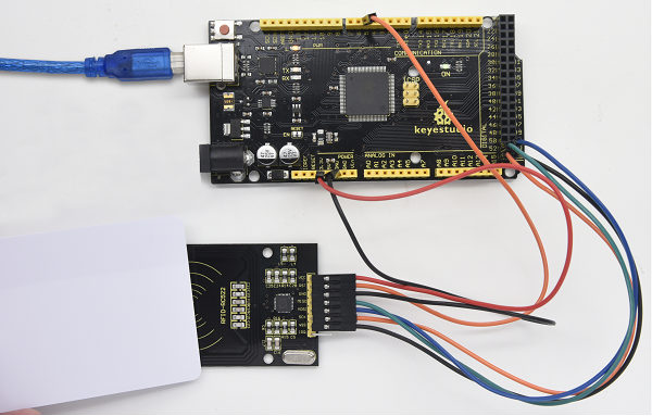
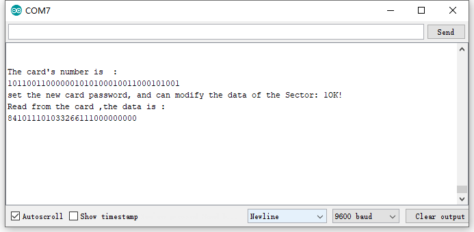
7. Resources
Download code, driver and library:
https://fs.keyestudio.com/KS0077-78-79
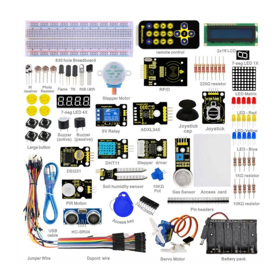
Hide thumbs
Also See for KS0077:
- Manual (109 pages)
-
Contents
-
Table of Contents
-
Bookmarks
Quick Links
keyestudio
Super Learning Kit for Arduino
www.keyestudio.com
1
Related Manuals for Keyestudio KS0077
Summary of Contents for Keyestudio KS0077
-
Page 1
Super Learning Kit for Arduino www.keyestudio.com… -
Page 2: Table Of Contents
Content 1. Introduction……………………….. 3 2. Component List……………………..3 3. Project List……………………….9 4. Project Details……………………..10 Project 1: Hello World…………………..10 Project 2: LED Blinking………………….13 Project 3: PWM…………………….15 Project 4: Traffic Light………………….20 Project 5: LED Chasing Effect………………..23 Project 6: Button-Controlled LED……………….. 25 Project 7: Active Buzzer………………….28…
-
Page 3: Introduction
1. Introduction keyestudio super learning kit is suitable for Arduino enthusiasts. This kit includes 32 projects with detailed tutorials, starting from the basics to more complex projects. Different from other kits, it adds some functional modules, such as RFID, temperature and humidity module. There is connection diagram and code for each project, making it easy for you to learn.
-
Page 4
220 Ω Resistor 10K Ω Resistor 1K Ω resistor 10K Ω Potentiometer Buzzer (Active) Buzzer (Passive) Large Button Switch www.keyestudio.com… -
Page 5
Ball Tilt Sensor Photo Resistor Flame Sensor LM35 Temp Sensor IC 74HC595N 16-pin DIP 7-seg LED Segment Display 7-seg LED Segment Display 8*8 LED Matrix www.keyestudio.com… -
Page 6
2×16 LCD display IR Receiver IR Remote Control Servo Motor Stepper Driver Stepper Motor Joystick Module www.keyestudio.com… -
Page 7
Relay Module PIR Motion Sensor Analog Gas Sensor ADXL345 Three Axis Acceleration Module HC-SR04 Ultrasonic Sensor DS3231 Clock Module www.keyestudio.com… -
Page 8
DHT11 Temperature and Humidity Sensor Soil Humidity Sensor RC522 RFID Module RFID Card Access Key Pin Headers www.keyestudio.com… -
Page 9: Project List
830-hole Breadboard Dupont Wire Jumper Wire 6-cell AA Battery Case USB Cable 3. Project List Project 1: Hello World Project 2: LED Blinking Project 3: PWM Project 4: Traffic Light Project 5: LED Chasing Effect Project 6: Button-controlled LED Project 7: Active Buzzer www.keyestudio.com…
-
Page 10: Project Details
Project 8: Passive Buzzer Project 9: RGB LED Project 10: Photo Resistor Project 11: Flame Sensor Project 12: LM35 Temperature Sensor Project 13: Tilt Switch Project 14: IR Remote Control Project 15: Analog Value Reading Project 16: 74HC595 Project 17: 1-digit LED Segment Display…
-
Page 11
Sample Code After installing driver for Arduino, let’s open Arduino software and compile code that enables Arduino to print «Hello World!» under your instruction. Of course, you can compile code for Arduino to continuously echo «Hello World!» without instruction. A simple If () statement will do the instruction trick. -
Page 12
Test Result Click to open the serial monitor, input an “ R”, LED 13 will blink once, PC will receive the information from Arduino: Hello World After choosing the proper port, the experiment is easy for you! www.keyestudio.com… -
Page 13: Project 2: Led Blinking
Project 2: LED Blinking Introduction Blinking LED experiment is quite simple. In the «Hello World!» program, we have come across LED. This time, we are going to connect an LED to one of the digital pins rather than using LED13 soldered to the board.
-
Page 14
Connection for UNO R3: Connection for 2560 R3: www.keyestudio.com… -
Page 15: Project 3: Pwm
Sample Code ////////////////////////////////////////////////////////// int ledPin = 10; // define digital pin 10. void setup() pinMode(ledPin, OUTPUT);// define pin with LED connected as output. void loop() digitalWrite(ledPin, HIGH); // set the LED on. delay(1000); // wait for a second. digitalWrite(ledPin, LOW); // set the LED off.
-
Page 16
Introduction PWM, short for Pulse Width Modulation, is a technique used to encode analog signal level into digital ones. A computer cannot output analog voltage but only digital voltage values such as 0V or 5V. So we use a high resolution counter to encode a specific analog signal level by modulating the duty cycle of PMW. -
Page 17
1. The amplitude of pulse width (minimum / maximum) 2. The pulse period (The reciprocal of pulse frequency in one second) 3. The voltage level(such as:0V-5V) There are 6 PMW interfaces on Arduino, namely digital pin 3, 5, 6, 9, 10, and 11. In previous experiments, we have done «button-controlled LED», using digital signal to control digital pin,… -
Page 18
Connection for 2560 R3: Sample Code In the program compiling process, we will use the analogWrite (PWM interface, analog value) function. In this experiment, we will read the analog value of the potentiometer and assign the value to PWM port, so there will be corresponding change to the brightness of the LED. One final part will display the analog value on the screen. -
Page 19
Serial.println(val);// display value of val analogWrite(ledpin,val/4);// turn on LED and set up brightness ( maximum output of PWM is 255) delay(10);// wait for 0.01 second… -
Page 20: Project 4: Traffic Light
Project 4: Traffic Light Introduction In the previous program, we have done the LED blinking experiment with one LED. Now, it’s time to up the stakes to do a bit more complicated experiment-traffic light. Actually, these two experiments are similar. While in this traffic light experiment, we use three LEDs with different colors rather than an LED.
-
Page 21
Circuit Connection Connection for UNO R3: Connection for 2560 R3: www.keyestudio.com… -
Page 22
Sample Code Since it is a simulation of traffic lights, the blinking time of each LED should be the same with those in traffic lights system. In this program, we use Arduino delay () function to control delay time, which is much simpler than C language. -
Page 23: Project 5: Led Chasing Effect
Project 5: LED Chasing Effect Introduction We can see many billboards composed of colorful LEDs. They are constantly changing to form various effects. In this experiment, we compile a program to simulate chase effect. Hardware Required Red LED*6 220Ω Resistor *6…
-
Page 24
Connection for 2560 R3: Sample Code ////////////////////////////////////////////////////////// int BASE = 2 ; // the I/O pin for the first LED int NUM = 6; // number of LEDs void setup() for (int i = BASE; i < BASE + NUM; i ++) pinMode(i, OUTPUT);… -
Page 25: Project 6: Button-Controlled Led
(int i = BASE; i < BASE + NUM; i ++) digitalWrite(i, HIGH); // set I/O pins as “high”, turn on LEDs one by one delay(200); // delay ////////////////////////////////////////////////////////// Result You can see the LEDs blink by sequence.
-
Page 26
Hardware Required Button switch*1 Red M5 LED*1 220ΩResistor*1 10KΩ Resistor*1 Breadboard*1 Breadboard Jumper Wires Circuit Connection Connection for UNO R3: Connection for 2560 R3: www.keyestudio.com… -
Page 27
Sample Code Now, let’s begin the compiling. When the button is pressed, the LED will be on. Based on the previous study, the coding should be easy for you. In this program, we add a statement of judgment. Here, we use an if () statement. -
Page 28: Project 7: Active Buzzer
7 and assign if to val if(val==LOW)// check if the button is pressed, if yes, turn on the LED { digitalWrite(ledpin,LOW);} else { digitalWrite(ledpin,HIGH);} ////////////////////////////////////////////////////////// Test Result When the button is pressed, LED is on, otherwise, LED remains off. In this way, the button controlled LED experiment is completed.
-
Page 29
Hardware Required Buzzer*1 Key *1 Breadboard*1 Breadboard Jumper Wires Circuit Connection Connection for UNO R3: Connection for 2560 R3: www.keyestudio.com… -
Page 30
When connecting the circuit, pay attention to the positive and negative poles of the buzzer. In the photo, you can see there are red and black lines. When the circuit is finished, you can begin the programming. Sample Code Program is simple. -
Page 31: Project 8: Passive Buzzer
Project 8: Passive Buzzer Introduction We can use Arduino to make many interactive works. The most commonly used one is acoustic-optic display. All the previous experiment has something to do with LED. However, the circuit in this experiment can produce sound. Normally, the experiment is done with a buzzer but not a speaker while buzzer is more simpler and easier to use.
-
Page 32
Connection for 2560 R3: www.keyestudio.com… -
Page 33
Sample Code ////////////////////////////////////////////////////////// int buzzer=8;// select digital IO pin for the buzzer void setup() pinMode(buzzer,OUTPUT);// set digital IO pin pattern, OUTPUT to be output void loop() { unsigned char i,j;//define variable while(1) { for(i=0;i<80;i++)// output a frequency sound { digitalWrite(buzzer,HIGH);// sound delay(1);//delay1ms… -
Page 34: Project 9: Rgb Led
Project 9: RGB LED Introduction Tricolor principle to display various colors; PWM controlling ports to display full color; Can be driven directly by Arduino PWM interface. Hardware Required Arduino Board* 1 USB Cable * 1 RGB LED * 1…
-
Page 35
Circuit Connection Connection for UNO R3: Connection for 2560 R3: www.keyestudio.com… -
Page 36
Sample Code ////////////////////////////////////////////////////////// int redpin = 11; //select the pin for the red LED int bluepin =10; // select the pin for the blue LED int greenpin =9;// select the pin for the green LED int val; void setup() { pinMode(redpin, OUTPUT);… -
Page 37: Project 10: Photo Resistor
Project 10: Photo Resistor Introduction After completing all the previous experiments, you may acquire some basic understanding and knowledge about Arduino application. We have introduced digital input and output, analog input and PWM. Now, let’s begin the learning of sensor applications.
-
Page 38
Hardware Required Photo Resistor*1 Red M5 LED*1 10KΩ Resistor*1 220Ω Resistor*1 Breadboard*1 Breadboard Jumper Wires Circuit Connection Connection for UNO R3: www.keyestudio.com… -
Page 39
Connection for 2560 R3: Sample Code After wiring, let’s begin the program compiling. The program is similar to the PWM. For change detail, please refer to the Sample Code below. ////////////////////////////////////////////////////////// int potpin=0;// initialize analog pin 0, connected with photovaristor int ledpin=11;// initialize digital pin 11, output regulating the brightness of LED… -
Page 40: Project 11: Flame Sensor
0.01 ////////////////////////////////////////////////////////// Test Result After downloading the program, you can change the light strength around the photovaristor, and see the corresponding brightness change of the LED. Photovaristors has various applications in our everyday. You can make other interesting interactive projects based on this one.
-
Page 41
Hardware Required Flame Sensor *1 Buzzer *1 10K Resistor *1 Breadboard Jumper Wires Circuit Connection 1)Connecting buzzer: Connect the controller board, prototype board, breadboard and USB Cable according to the Arduino tutorial. Connect the buzzer to digital pin 8. -
Page 42
Connection for MEGA 2560: www.keyestudio.com… -
Page 43
Experiment Principle When it’s approaching a fire, the voltage value read from the analog port will differ. If you use a multimeter, you can see that when there is no fire approaching, the voltage it reads is around 0.3V;… -
Page 44: Project 12: Lm35 Temperature Sensor
Project 12: LM35 Temperature Sensor Introduction LM35 is a common and easy-to-use temperature sensor. It does not require other hardware. You just need an analog port to make it work. The difficulty lies in compiling the code to convert the analog value it reads into Celsius temperature.
-
Page 45
Connection for UNO R3: Connection for 2560 R3: www.keyestudio.com… -
Page 46
Sample Code ////////////////////////////////////////////////////////// int potPin = 0; // initialize analog pin 0 for LM35 temperature sensor void setup() Serial.begin(9600);// set baud rate at”9600” void loop() int val;// define variable int dat;// define variable val=analogRead(0);// read the analog value of the sensor and assign it to val dat=(125*val)>>8;// temperature calculation formula… -
Page 47: Project 13: Tilt Switch
Project 13: Tilt Switch Introduction Tilt switch controlling the LED on and off. Hardware Required Ball switch*1 Led *1 220Ω Resistor*1 10KΩ resistor*1 Breadboard Jumper Wires Circuit Connection Connection for R3: www.keyestudio.com…
-
Page 48
Connection for 2560 R3: Connect the controller board, shield, breadboard and USB cable according to Arduino tutorial. Connect the LED to digital pin 8, ball switch to analog pin 5. Experiment Principle When one end of the switch is below horizontal position, the switch is on. The voltage of the analog port is about 5V (1023 in binary). -
Page 49: Project 14: Ir Remote Control
5 if(i>512)// if larger that 512(2.5V) digitalWrite(8,LOW);// turn on LED else// otherwise digitalWrite(8,HIGH);// turn off LED ////////////////////////////////////////////////////////// Test Result Hold the breadboard with your hand. Tilt it to a certain extent, the LED will be on. If there is no tilt, the LED will be off.
-
Page 50
Introduction What is an infrared receiver? The signal from the infrared remote controller is a series of binary pulse code. To avoid the other infrared signal interference during the wireless transmission, the signal is pre-modulate at a specific carrier frequency and then send out by an infrared emission diode. The infrared receiving device needs to filter out other waves and receive signals at that specific frequency and to modulate it back to binary pulse code, known as demodulation. -
Page 51
Hardware Required Infrared Remote Controller *1 Infrared Receiver *1 LED *6 220ΩResistor *6 Multi-color Breadboard Wires Circuit Connection First, connect the controller board; then connect the infrared receiver as the above mentioned, connect VOUT to digital pin 11, connect the LEDs with resistors and connect the resistors to pin 2,3,4,5,6,7. -
Page 52
Connection for 2560 R3: Experimental Principle If you want to decode the code from the remote controller, you must first know how it’s coded. The coding method we use here is NEC protocol. Below is a brief introduction. • NEC protocol: Features:… -
Page 53
• Pulse transmitted when button is pressed and immediately released The picture above shows a typical pulse train of the NEC protocol. With this protocol the LSB is transmitted first. In this case Address $59 and Command $16 is transmitted. A message is started by a 9ms AGC burst, which was used to set the gain of the earlier IR receivers. -
Page 54
Sample Code ////////////////////////////////////////////////////////// #include <IRremote.h> int RECV_PIN = 11; int LED1 = 2; int LED2 = 3; int LED3 = 4; int LED4 = 5; int LED5 = 6; int LED6 = 7; long on1 = 0x00FF6897; long off1 = 0x00FF9867;… -
Page 55
Serial.print(«Decoded SONY: «); else if (results->decode_type == RC5) Serial.print(«Decoded RC5: «); else if (results->decode_type == RC6) Serial.print(«Decoded RC6: «); Serial.print(results->value, HEX); Serial.print(» («); Serial.print(results->bits, DEC); Serial.println(» bits)»); Serial.print(«Raw («); Serial.print(count, DEC); Serial.print(«): «); for (int i = 0; i < count; i++) if ((i % 2) == 1) { Serial.print(results->rawbuf[i]*USECPERTICK, DEC);… -
Page 56
Serial.begin(9600); irrecv.enableIRIn(); // Start the receiver int on = 0; unsigned long last = millis(); void loop() if (irrecv.decode(&results)) // If it’s been at least 1/4 second since the last // IR received, toggle the relay if (millis() — last > 250) on = !on;… -
Page 57
LOW); last = millis(); irrecv.resume(); // Receive the next value ////////////////////////////////////////////////////////// Note:add IRremote folder into installation directory Arduinocompiler libraries, or you will fail to compile it. Infrared remote library: https://github.com/shirriff/Arduino-IRremote Program Function Decode the coded pulse signal emitted by the remote controller, then execute corresponding action according to the results of the decoding. -
Page 58: Project 15: Analog Value Reading
Project 15: Analog Value Reading Introduction In this experiment, we will begin the study of analog I/O interfaces. On an Arduino, there are 6 analog interfaces numbered from 0 to 5. These 6 interfaces can also be used as digital ones numbered as 14-19.
-
Page 59
Connection for 2560 R3: www.keyestudio.com… -
Page 60
Sample Code The program compiling is simple. An analogRead () Statement can read the value of the interface. The A/D acquisition of Arduino 328 is in 10 bits, so the value it reads is among 0 to 1023. One difficulty in this project is to display the value on the screen, which is actually easy to learn. -
Page 61
The experiment is now completed. Thank you! ******************************************************************************* Project 16: 74HC595 Introduction To put it simply, 74HC595 is a combination of 8-digit shifting register, memorizer and equipped with tri-state output. Here, we use it to control 8 LEDs. You may wonder why use a 74HC595 to control LED? Well, think about how many I/O it takes for an Arduino to control 8 LEDs? Yes, 8. -
Page 62
Hardware Required 74HC595 chip*1 Red M5 LED*4 Green M5 LED*4 220Ω Resistor*8 Breadboard*1 Breadboard Jumper Wires Circuit Connection Connection for UNO R3: Note: for pin 13 OE port of 74HC595, it should be connected to GND. www.keyestudio.com… -
Page 63
Connection for 2560 R3: The circuit may seem complicated, but once you wire it in order, you will find it more easier! Sample Code ////////////////////////////////////////////////////////// int data = 2;// set pin 14 of 74HC595as data input pin SI int clock = 5;// set pin 11 of 74hc595 as clock pin SCK int latch = 4;// set pin 12 of 74hc595 as output latch RCK… -
Page 64: Project 17: 1-Digit Led Segment Display
= 0; i < 256; i++) updateLEDs(i); delay(500); void updateLEDs(int value) digitalWrite(latch, LOW);// shiftOut(data, clock, MSBFIRST, ~value);// serial data “output”, high level first digitalWrite(latch, HIGH);// latch ////////////////////////////////////////////////////////// Test Result After downloading the program, you can see 8 LEDs display 8-bit binary number.
-
Page 65
8-segment display has one more LED unit ( for decimal point display) than 7-segment one. According to the wiring method of LED units, LED segment display can be divided into common anode display and common cathode display. Common anode display refers to the one that combine all the anodes of LED units into one common anode (COM). -
Page 66
Connection for 2560 R3: www.keyestudio.com… -
Page 67
Sample Code There are seven segments for numerical display, one for decimal point display. Corresponding segments will be turned on when displaying certain numbers. For example, when displaying number 1, b and c segments will be turned on. We compile a subprogram for each number, and compile the main program to display one number every 2 seconds, cycling display number 0 ~ 9. -
Page 68
// display number 3 {digitalWrite(g,HIGH); digitalWrite(a,HIGH); digitalWrite(b,HIGH); digitalWrite(c,HIGH); digitalWrite(d,HIGH); digitalWrite(dp,LOW); digitalWrite(f,LOW); digitalWrite(e,LOW); void digital_4(void) // display number 4 {digitalWrite(c,HIGH); digitalWrite(b,HIGH); digitalWrite(f,HIGH); digitalWrite(g,HIGH); digitalWrite(dp,LOW); digitalWrite(a,LOW); digitalWrite(e,LOW); digitalWrite(d,LOW); void digital_5(void) // display number 5 unsigned char j;… -
Page 69
// display number 7 unsigned char j; for(j=5;j<=7;j++) digitalWrite(j,HIGH); digitalWrite(dp,LOW); for(j=8;j<=11;j++) digitalWrite(j,LOW); void digital_8(void) // display number 8 unsigned char j; for(j=5;j<=11;j++) digitalWrite(j,HIGH); digitalWrite(dp,LOW); void digital_9(void) // display number 5 unsigned char j;… -
Page 70
0 delay(1000);// wait for 1s digital_1();// display number 1 delay(1000);// wait for 1s digital_2();// display number 2 delay(1000); // wait for 1s digital_3();// display number 3 delay(1000); // wait for 1s digital_4();// display number 4 delay(1000);… -
Page 71: Project 18: 4-Digit Led Segment Display
Project 18: 4-digit LED Segment Display Introduction In this experiment, we use an Arduino to drive a common cathode, 4-digit, 7-segment LED display. For LED display, current-limiting resistors are indispensable. There are two wiring methods for Current-limiting resistor. One is to connect one resistor for each cathode end, 4 in total for d1-d4 cathode.
-
Page 72
Manual for LED Segment Display: Connection for UNO R3: www.keyestudio.com… -
Page 73
Connection for 2560 R3: Sample Code ////////////////////////////////////////////////////////// // display 1234 // select pin for cathode int a = 1; int b = 2; int c = 3; int d = 4; int e = 5; int f = 6;… -
Page 74
OUTPUT); pinMode(d, OUTPUT); pinMode(e, OUTPUT); pinMode(f, OUTPUT); pinMode(g, OUTPUT); pinMode(dp, OUTPUT); ///////////////////////////////////////////////////////////// void loop() Display(1, 1); Display(2, 2); Display(3, 3); Display(4, 4); /////////////////////////////////////////////////////////////// void WeiXuan(unsigned char n)// switch(n) case 1: digitalWrite(d1,LOW); digitalWrite(d2, HIGH); digitalWrite(d3, HIGH); digitalWrite(d4, HIGH); break;… -
Page 75
HIGH); digitalWrite(d4, LOW); break; default : digitalWrite(d1, HIGH); digitalWrite(d2, HIGH); digitalWrite(d3, HIGH); digitalWrite(d4, HIGH); break; void Num_0() digitalWrite(a, HIGH); digitalWrite(b, HIGH); digitalWrite(c, HIGH); digitalWrite(d, HIGH); digitalWrite(e, HIGH); digitalWrite(f, HIGH); digitalWrite(g, LOW); digitalWrite(dp,LOW); void Num_1() digitalWrite(a, LOW); digitalWrite(b, HIGH);… -
Page 76
Num_3() digitalWrite(a, HIGH); digitalWrite(b, HIGH); digitalWrite(c, HIGH); digitalWrite(d, HIGH); digitalWrite(e, LOW); digitalWrite(f, LOW); digitalWrite(g, HIGH); digitalWrite(dp,LOW); void Num_4() digitalWrite(a, LOW); digitalWrite(b, HIGH); digitalWrite(c, HIGH); digitalWrite(d, LOW); digitalWrite(e, LOW); digitalWrite(f, HIGH); digitalWrite(g, HIGH); digitalWrite(dp,LOW); void Num_5() digitalWrite(a, HIGH);… -
Page 77
HIGH); digitalWrite(g, HIGH); digitalWrite(dp,LOW); void Num_7() digitalWrite(a, HIGH); digitalWrite(b, HIGH); digitalWrite(c, HIGH); digitalWrite(d, LOW); digitalWrite(e, LOW); digitalWrite(f, LOW); digitalWrite(g, LOW); digitalWrite(dp,LOW); void Num_8() digitalWrite(a, HIGH); digitalWrite(b, HIGH); digitalWrite(c, HIGH); digitalWrite(d, HIGH); digitalWrite(e, HIGH); digitalWrite(f, HIGH); digitalWrite(g, HIGH); digitalWrite(dp,LOW);… -
Page 78
LOW); digitalWrite(e, LOW); digitalWrite(f, LOW); digitalWrite(g, LOW); digitalWrite(dp,LOW); void pickNumber(unsigned char n)// select number switch(n) case 0:Num_0(); break; case 1:Num_1(); break; case 2:Num_2(); break; case 3:Num_3(); break; case 4:Num_4(); break; case 5:Num_5(); break; case 6:Num_6(); break; case 7:Num_7();… -
Page 79: Project 19: 8*8 Led Matrix
Result Download the above code to the controller board, you can see the LED display shows the number 1234. Note: if it’s not displaying correctly, check the wiring. The experiment is over. Thank you! ****************************************************************************** Project 19: 8*8 LED Matrix…
-
Page 80
The external view of a dot-matrix is shown as follows: The display principle of the 8*8 dot-matrix: The 8*8 dot-matrix is made up of sixty-four LEDs, and each LED is placed at the cross point of a row and a column. When the electrical level of a certain row is 1 and the electrical level of a certain column is 0, the corresponding LED will lighten. -
Page 81
Connection for UNO R3: Connection for 2560 R3: Sample Code for displaying “0” ////////////////////////////////////////////////////////// // set an array to store character of “0” unsigned char Text[]={0x00,0x1c,0x22,0x22,0x22,0x22,0x22,0x1c}; void Draw_point(unsigned char x,unsigned char y)// point drawing function { clear_(); digitalWrite(x+2, HIGH);… -
Page 82
& 0x01)Draw_point(j,i); data>>=1; void setup(){ int i = 0 ; for(i=2;i<18;i++) pinMode(i, OUTPUT); clear_(); void loop() { show_num(); void clear_(void)// clear screen {for(int i=2;i<10;i++) digitalWrite(i, LOW);… -
Page 83: Project 20: 1602 Lcd
Project 20: 1602 LCD Introduction In this experiment, we use an Arduino to drive the 1602 LCD. 1602 LCD has wide applications. In the beginning, 1602 LCD uses a HD44780 controller. Now, almost all 1602 LCD module uses a compatible IC, so their features are basically the same.
-
Page 84
Interface Description: 1. two power sources, one for module power, another one for back light, generally use 5V. In this project, we use 3.3V for back light. 2. VL is the pin for adjusting contrast ratio; it usually connects a potentiometer(no more than 5KΩ) in series for its adjustment. -
Page 85
8-bit Connection Method: Connection for UNO R3: www.keyestudio.com… -
Page 86
Connection for 2560 R3: Sample Code A: ////////////////////////////////////////////////////////// int DI = 12; int RW = 11; int DB[] = {3, 4, 5, 6, 7, 8, 9, 10};// use array to select pin for bus int Enable = 2; void LcdCommandWrite(int value) { // define all pins int i = 0;… -
Page 87
HIGH); digitalWrite(RW, LOW); for (i=DB[0]; i <= DB[7]; i++) { digitalWrite(i,value & 01); value >>= 1; digitalWrite(Enable,LOW); delayMicroseconds(1); digitalWrite(Enable,HIGH); delayMicroseconds(1); digitalWrite(Enable,LOW); delayMicroseconds(1); // wait for 1ms void setup (void) { int i = 0; for (i=Enable; i <= DI; i++) { pinMode(i,OUTPUT);… -
Page 88
(void) { LcdCommandWrite(0x01); // clear the scree, cursor position returns to 0 delay(10); LcdCommandWrite(0x80+3); delay(10); // write in welcome message LcdDataWrite(‘W’); LcdDataWrite(‘e’); LcdDataWrite(‘l’); LcdDataWrite(‘c’); LcdDataWrite(‘o’); LcdDataWrite(‘m’); LcdDataWrite(‘e’); LcdDataWrite(‘ ‘); LcdDataWrite(‘t’); LcdDataWrite(‘o’); delay(10); LcdCommandWrite(0xc0+1); // set cursor position at second line, second position delay(10);… -
Page 89
LcdDataWrite(‘n’); LcdDataWrite(‘g’); LcdDataWrite(‘y’); LcdDataWrite(‘i’); delay(3000); LcdCommandWrite(0x02); // set mode as new characters replay old ones, where there is no new ones remain the same delay(10); LcdCommandWrite(0x80+5); // set cursor position at first line, sixth position delay(10); LcdDataWrite(‘t’); LcdDataWrite(‘h’); LcdDataWrite(‘e’);… -
Page 90
Connection for 2560 R3: After the connection, upload below code to the controller board and see how it goes. Sample Code B: ////////////////////////////////////////////////////////// LiquidCrystal Library — Hello World Demonstrates the use a 16×2 LCD display. The LiquidCrystal library works with all LCD displays that are compatible with the Hitachi HD44780 driver. -
Page 91
* 10K resistor: * ends to +5V and ground * wiper to LCD VO pin (pin 3) Library originally added 18 Apr 2008 by David A. Mellis library modified 5 Jul 2009 by Limor Fried (http://www.ladyada.net) example added 9 Jul 2009… -
Page 92: Project 21: 9G Servo Control
Project 21: 9g Servo Control Introduction Servomotor is a position control rotary actuator. It mainly consists of housing, circuit board, core-less motor, gear and position sensor. The receiver or MCU outputs a signal to the servomotor. The motor has a built-in reference circuit that gives out reference signal, cycle of 20ms and width of 1.5ms.
-
Page 93
The rotate angle of the servo motor is controlled by regulating the duty cycle of the PWM(Pulse-Width Modulation) signal. The standard cycle of the PWM signal is 20ms(50Hz). Theoretically, the width is distributed between 1ms-2ms, but in fact, it’s between 0.5ms-2.5ms. -
Page 94
Connection for 2560 R3: Connect the motor to digital pin 9. www.keyestudio.com… -
Page 95
Compile a program to control the motor to rotate in the commanded angle, and display the angle on the screen. Sample Code A ////////////////////////////////////////////////////////// int servopin=9;// select digital pin 9 for servomotor signal line int myangle;// initialize angle variable int pulsewidth;// initialize width variable… -
Page 96
Method 2: Let’s first take a look at the Arduino built-in servo function and some common statements. 1. attach(interface)——select pin for servo, can only use pin 9 or 10. 2. write ( angle) ——used to control the rotate angle of the servo, can set the angle among 0 degree to 180 degree. -
Page 97: Project 22: 5V Stepper Motor
Project 22: 5V Stepper Motor Introduction A stepper motor is an electromechanical device which can convert electrical pulses into discrete mechanical movements. The shaft or spindle of a stepper motor rotates in discrete step increments when electrical command pulses are applied to it in the proper sequence. The motors rotation has several direct relationships to these applied input pulses.
-
Page 98
• A wide range of rotational speeds can be realized as the speed is proportional to the frequency of the input pulses. Parameters of Stepper Motor 28BYJ-48 Model: 28BYJ-48 Rated Voltage: 5VDC Number of Phase: 4 Speed Variation Ratio: 1/64 Stride Angle: 5.625°… -
Page 99
Connection for 2560 R3: Sample Code ////////////////////////////////////////////////////////// #include <Stepper.h> #define STEPS 100 Stepper stepper(STEPS, 8, 9, 10, 11); int previous = 0; void setup() stepper.setSpeed(90); void loop() int val = analogRead(0); stepper.step(val — previous); previous = val; ////////////////////////////////////////////////////////// www.keyestudio.com… -
Page 100: Project 23: Pir Motion Sensor
Project 23: PIR Motion Sensor Introduction Pyroelectric infrared motion sensor can detect infrared signals from a moving person or moving animal, and output switching signals. It can be applied to a variety of occasions to detect the movement of human body. Conventional pyroelectric infrared sensors require body pyroelectric infrared detector, professional chip, complex peripheral circuit, so it is more bigger with complex circuit, and lower reliability.
-
Page 101
Connection for UNO R3: Connection for MEGA 2560 R3: Sample Code ////////////////////////////////////////////////////////// byte sensorPin = 3; byte indicator = 13; void setup() pinMode(sensorPin,INPUT); pinMode(indicator,OUTPUT); Serial.begin(9600); www.keyestudio.com… -
Page 102: Project 24: Analog Gas Sensor
= digitalRead(sensorPin); digitalWrite(indicator,state); if(state == 1)Serial.println(«Somebody is in this area!»); else if(state == 0)Serial.println(«No one!»); delay(500); ////////////////////////////////////////////////////////// Project 24: Analog Gas Sensor Introduction This analog gas sensor — MQ2 is used in gas leakage detecting equipment in consumer electronics and industrial markets.
-
Page 103
Stable and long lifespan Size: 49.7*20mm Weight: 8g Circuit Connection Connection for UNO R3: Connection for MEGA 2560 R3: Sample Code ////////////////////////////////////////////////////////// void setup() Serial.begin(9600); //Set serial baud rate to 9600 bps www.keyestudio.com… -
Page 104: Project 25: Adxl345 Three Axis Acceleration Module
{int val; val=analogRead(0);//Read Gas value from analog 0 Serial.println(val,DEC);//Print the value to serial port delay(100); ////////////////////////////////////////////////////////// Project 25: ADXL345 Three Axis Acceleration Module Introduction The ADXL345 is a small, thin, low power, 3-axis MEMS accelerometer with high resolution (13-bit) measurement at up to +-16 g.
-
Page 105
Circuit Connection Connection for UNO R3: Connection for MEGA 2560 R3: www.keyestudio.com… -
Page 106
Sample Code /////////////////////////////////////////////////////////////////////////////////////////////////////////////////// The circuit: VCC: 5V GND: ground SCL: UNO SLC SDA: UNO SDA This example code is in the public domain. #include <Wire.h> // Registers for ADXL345 #define ADXL345_ADDRESS (0xA6 >> 1) // address for device is 8 bit but shift to the… -
Page 107
// Connect to device Wire.beginTransmission(address); // Request data from slave // Count stands for number of bytes to request Wire.requestFrom(address, count); while(Wire.available()) // slave may send less than requested char c = Wire.read(); // receive a byte as character data[i] = c;… -
Page 108
// initialise and start everything void setup() { Wire.begin(); Serial.begin(9600); for(int i=0; i<3; ++i) { accelerometer_data[i] = 0; init_adxl345(); void loop() { read_adxl345(); Serial.print(«ACCEL: «); Serial.print(float(accelerometer_data[0])*3.9/1000);//3.9mg/LSB scale factor in 13-bit mode Serial.print(«t»); Serial.print(float(accelerometer_data[1])*3.9/1000); Serial.print(«t»); Serial.print(float(accelerometer_data[2])*3.9/1000); Serial.print(«n»); delay(100); //////////////////////////////////////////////////////////////////////////////////////////////////////////////////// www.keyestudio.com… -
Page 109: Project 26: Hc-Sr04 Ultrasonic Sensor
Project 26: HC-SR04 Ultrasonic Sensor Introduction The HC-SR04 Ultrasonic Sensor is a very affordable proximity/distance sensor that is mainly used for object avoidance in various robotics projects. It essentially gives your Arduino eyes / spacial awareness and can prevent your robot from crashing or falling off a table. It has also been used in turret applications, water level sensing, and even as a parking sensor.
-
Page 110
Connection for MEGA 2560 R3: Sample Code ////////////////////////////////////////////////////////// VCC to arduino 5v GND to arduino GND Echo to Arduino pin 7 Trig to Arduino pin 8 #define echoPin 7 // Echo Pin #define trigPin 8 // Trigger Pin #define LEDPin 13 // Onboard LED int maximumRange = 200;… -
Page 111
// Duration used to calculate distance void setup() { Serial.begin (9600); pinMode(trigPin, OUTPUT); pinMode(echoPin, INPUT); pinMode(LEDPin, OUTPUT); // Use LED indicator (if required) void loop() { /* The following trigPin/echoPin cycle is used to determine the distance of the nearest object by bouncing soundwaves off of it. -
Page 112: Project 27: Joystick Module
Project 27: Joystick Module Introduction Lots of robot projects need joystick. This module provides an affordable solution. By simply connecting to two analog inputs, the robot is at your commands with X, Y control. It also has a switch that is connected to a digital pin. This joystick module can be easily connected to Arduino by IO Shield.
-
Page 113
Connection for MEGA 2560 R3: Sample Code ////////////////////////////////////////////////////////// int JoyStick_X = 0; //x int JoyStick_Y = 1; //y int JoyStick_Z = 3; //key void setup() pinMode(JoyStick_Z, INPUT); Serial.begin(9600); // 9600 bps void loop() int x,y,z; x=analogRead(JoyStick_X); y=analogRead(JoyStick_Y); z=digitalRead(JoyStick_Z); Serial.print(x ,DEC);… -
Page 114: Project 28: 5V Relay Module
Project 28: 5V Relay Module Introduction This single relay module can be used in interactive projects. This module uses SONGLE 5v high-quality relay. It can also be used to control the lighting, electrical and other equipment. The modular design makes it easy to expand with the Arduino Board (not included).
-
Page 115
Connection for UNO R3: Connection for MEGA 2560 R3: Sample Code ////////////////////////////////////////////////////////// int Relay = 8; void setup() pinMode(13, OUTPUT); //Set Pin13 as output digitalWrite(13, HIGH); //Set Pin13 High www.keyestudio.com… -
Page 116: Project 29: Ds3231 Clock Module
OUTPUT); //Set Pin3 as output void loop() digitalWrite(Relay, HIGH); //Turn off relay delay(2000); digitalWrite(Relay, LOW); //Turn on relay delay(2000); ////////////////////////////////////////////////////////// Project 29: DS3231 Clock Module Introduction DS3231 is equipped with integrated TCXO and crystal, which makes it a cost-effective I2C real time clock with high precision.
-
Page 117
Specification • Temperature Range: -40 to +85; • Timing Accuracy : ± 5ppm (±0.432 seconds / day) • Provide battery backup for continuous timing • Low power consumption • Device package and function compatible with DS3231 • Complete clock calendar function contains seconds and minutes, hour, week, date, month, and year timing and provides leap year compensation until 2100. -
Page 118
Connection for MEGA 2560 R3: Sample Code ////////////////////////////////////////////////////////// #include <Wire.h> #include «DS3231.h» DS3231 RTC; //Create the DS3231 object char weekDay[][4] = {«Sun», «Mon», «Tue», «Wed», «Thu», «Fri», «Sat» }; //year, month, date, hour, min, sec and week-day(starts from 0 and goes to 6) //writing any non-existent time-data may interfere with normal operation of the RTC. -
Page 119
Serial.print(now.minute(), DEC); Serial.print(‘:’); Serial.print(now.second(), DEC); Serial.println(); Serial.print(weekDay[now.dayOfWeek()]); Serial.println(); delay(1000); ////////////////////////////////////////////////////////// Before compiling the code, you’d better put DS3231 library under file into Arduino catalogue. Test Result Done uploading the code to arduino, open the serial monitor and get the following results:… -
Page 120: Project 30: Dht11 Temperature And Humidity Sensor
Project 30: DHT11 Temperature and Humidity Sensor Introduction This DHT11 Temperature and Humidity Sensor features calibrated digital signal output with the temperature and humidity sensor complex. Its technology ensures high reliability and excellent long-term stability. A high-performance 8-bit microcontroller is connected.
-
Page 121
Circuit Connection Connection for UNO R3: Connection for MEGA 2560 R3: Sample Code Please download the DHT11Lib firstly. Or see the website ////////////////////////////////////////////////////////// #include <dht11.h> dht11 DHT; #define DHT11_PIN 4 void setup(){ Serial.begin(9600); Serial.println(«DHT TEST PROGRAM «); Serial.print(«LIBRARY VERSION: «);… -
Page 122
Serial.println(«Type,tstatus,tHumidity (%),tTemperature (C)»); void loop(){ int chk; Serial.print(«DHT11, t»); chk = DHT.read(DHT11_PIN); // READ DATA switch (chk){ case DHTLIB_OK: Serial.print(«OK,t»); break; case DHTLIB_ERROR_CHECKSUM: Serial.print(«Checksum error,t»); break; case DHTLIB_ERROR_TIMEOUT: Serial.print(«Time out error,t»); break; default: Serial.print(«Unknown error,t»); break; // DISPLAT DATA Serial.print(DHT.humidity,1);… -
Page 123: Project 31: Soil Humidity Sensor
Project 31: Soil Humidity Sensor Introduction This is a simple soil humidity sensor aims to detect the soil humidity. If the soil is lack of water, the analog value output by the sensor will decrease; otherwise, it will increase. If you use this sensor to make an automatic watering device, it can detect whether your botany is thirsty so as to prevent it from withering when you go out.
-
Page 124
Circuit Connection Connection for UNO R3: Connection for MEGA 2560 R3: Sample Code ////////////////////////////////////////////////////////// # 0 ~300 dry soil # 300~700 humid soil # 700~950 in water void setup(){ www.keyestudio.com… -
Page 125: Project 32: Rc522 Rfid Module
Serial.begin(57600); void loop(){ Serial.print(«Moisture Sensor Value:»); Serial.println(analogRead(0)); delay(100); ////////////////////////////////////////////////////////// Project 32: RC522 RFID Module Introduction MF522-AN module adopts Philips MFRC522 original reader circuit chip design, easy to use, low cost, suitable for equipment development, development of advanced applications, the need for the user of RF card terminal design / production.
-
Page 126
Supported card types: mifare1 S50, mifare1 S70, mifare UltraLight, mifare Pro, mifare Desfire Dimension: 40mm * 60mm Environmental Operating Temperature: -20-80 degrees Celsius Environment Storage Temperature: -40-85 degrees Celsius 10. Relative Humidity: 5% -95% Circuit Connection Connection for UNO R3:… -
Page 127
Connection for 2560 R3: Sample Code ////////////////////////////////////////////////////////// #include <SPI.h> #define uchar unsigned char #define uint unsigned int #define MAX_LEN 16 const int chipSelectPin = 10;//if the controller is UNO,328,168 const int NRSTPD = 5; //MF522command word #define PCD_IDLE 0x00 //NO action;concel current command… -
Page 128
#define PICC_READ 0x30 // Reader Module #define PICC_WRITE 0xA0 // letter block #define PICC_DECREMENT 0xC0 #define PICC_INCREMENT 0xC1 #define PICC_RESTORE 0xC2 //Transfer data to buffer #define PICC_TRANSFER 0xB0 //Save buffer data #define PICC_HALT 0x50 //Dormancy //MF522 Error code returned when communication… -
Page 129
#define RxThresholdReg 0x18 #define DemodReg 0x19 #define Reserved11 0x1A #define Reserved12 0x1B #define MifareReg 0x1C #define Reserved13 0x1D #define Reserved14 0x1E #define SerialSpeedReg 0x1F //Page 2:CFG #define Reserved20 0x20 #define CRCResultRegM 0x21 #define CRCResultRegL 0x22 #define Reserved21 0x23 #define… -
Page 130
={‘T’, ‘e’, ‘n’, ‘g’, ‘ ‘, ‘B’, ‘o’, 0, 0, 0, 0, 0, 0, 0, 0,0}; uchar sectorKeyA[16][16] = {{0xFF, 0xFF, 0xFF, 0xFF, 0xFF, 0xFF}, {0xFF, 0xFF, 0xFF, 0xFF, 0xFF, 0xFF}, {0xFF, 0xFF, 0xFF, 0xFF, 0xFF, 0xFF},… -
Page 131
= MFRC522_Anticoll(str); memcpy(serNum, str, 5); if (status == MI_OK) Serial.println(«The card’s number is : «); Serial.print(serNum[0],BIN); Serial.print(serNum[1],BIN); Serial.print(serNum[2],BIN); Serial.print(serNum[3],BIN); Serial.print(serNum[4],BIN); Serial.println(» «); // select card, return card capacity RC_size = MFRC522_SelectTag(serNum); if (RC_size != 0) // write data card blockAddr = 7;… -
Page 132
// read card blockAddr = 7; // data block 7 status MFRC522_Auth(PICC_AUTHENT1A, blockAddr, sectorNewKeyA[blockAddr/4], serNum); // authentication if (status == MI_OK) // read data blockAddr = blockAddr — 3 ; status = MFRC522_Read(blockAddr, str); if (status == MI_OK) Serial.println(«Read from the card ,the data is : «);… -
Page 133
SPI.transfer(((addr<<1)&0x7E) | 0x80); val =SPI.transfer(0x00); digitalWrite(chipSelectPin, HIGH); return val; void SetBitMask(uchar reg, uchar mask) uchar tmp; tmp = Read_MFRC522(reg); Write_MFRC522(reg, tmp | mask); // set bit mask void ClearBitMask(uchar reg, uchar mask) uchar tmp; tmp = Read_MFRC522(reg); Write_MFRC522(reg, tmp & (~mask)); // clear bit mask void AntennaOn(void) uchar temp;… -
Page 134
MFRC522_Reset(void) Write_MFRC522(CommandReg, PCD_RESETPHASE); void MFRC522_Init(void) digitalWrite(NRSTPD,HIGH); MFRC522_Reset(); //Timer: TPrescaler*TreloadVal/6.78MHz = 24ms Write_MFRC522(TModeReg, 0x8D); //Tauto=1; f(Timer) = 6.78MHz/TPreScaler Write_MFRC522(TPrescalerReg, 0x3E); //TModeReg[3..0] + TPrescalerReg Write_MFRC522(TReloadRegL, 30); Write_MFRC522(TReloadRegH, 0); Write_MFRC522(TxAutoReg, 0x40); //100%ASK Write_MFRC522(ModeReg, 0x3D); //CRC initial value AntennaOn(); // open antenna uchar MFRC522_Request(uchar reqMode, uchar *TagType) uchar status;… -
Page 135
MFRC522_ToCard(uchar command, uchar *sendData, uchar sendLen, uchar *backData, uint *backLen) uchar status = MI_ERR; uchar irqEn = 0x00; uchar waitIRq = 0x00; uchar lastBits; uchar n; uint i; switch (command) case PCD_AUTHENT: // card key authentication irqEn = 0x12;… -
Page 136
Write_MFRC522(CommandReg, command); if (command == PCD_TRANSCEIVE) SetBitMask(BitFramingReg, 0x80); //StartSend=1,transmission of data starts // wait for the completion of data receiving i = 2000; // adjust i according to clock frequency, maximum waiting time of operating M1 is 25ms //CommIrqReg[7..0] //Set1 TxIRq RxIRq IdleIRq HiAlerIRq LoAlertIRq ErrIRq TimerIRq n = Read_MFRC522(CommIrqReg);… -
Page 137
(n == 0) n = 1; if (n > MAX_LEN) n = MAX_LEN; // read data which FIFO received for (i=0; i<n; i++) backData[i] = Read_MFRC522(FIFODataReg); else status = MI_ERR; //SetBitMask(ControlReg,0x80); //timer stops //Write_MFRC522(CommandReg, PCD_IDLE); return status; uchar MFRC522_Anticoll(uchar *serNum) uchar status;… -
Page 138
(status == MI_OK) // verify card sequence number for (i=0; i<4; i++) serNumCheck ^= serNum[i]; if (serNumCheck != serNum[i]) status = MI_ERR; //SetBitMask(CollReg, 0x80); //ValuesAfterColl=1 return status; void CalulateCRC(uchar *pIndata, uchar len, uchar *pOutData) uchar i, n; ClearBitMask(DivIrqReg, 0x04);… -
Page 139
// read CRC calculation result pOutData[0] = Read_MFRC522(CRCResultRegL); pOutData[1] = Read_MFRC522(CRCResultRegM); uchar MFRC522_SelectTag(uchar *serNum) uchar i; uchar status; uchar size; uint recvBits; uchar buffer[9]; //ClearBitMask(Status2Reg, 0x08); //MFCrypto1On=0 buffer[0] = PICC_SElECTTAG; buffer[1] = 0x70; for (i=0; i<5; i++) buffer[i+2] = *(serNum+i);… -
Page 140
// Verification commands + block address + sector password + card sequence number buff[0] = authMode; buff[1] = BlockAddr; for (i=0; i<6; i++) buff[i+2] = *(Sectorkey+i); for (i=0; i<4; i++) buff[i+8] = *(serNum+i); status = MFRC522_ToCard(PCD_AUTHENT, buff, 12, buff, &recvBits);… -
Page 141
= PICC_WRITE; buff[1] = blockAddr; CalulateCRC(buff, 2, &buff[2]); status = MFRC522_ToCard(PCD_TRANSCEIVE, buff, 4, buff, &recvBits); if ((status != MI_OK) || (recvBits != 4) || ((buff[0] & 0x0F) != 0x0A)) status = MI_ERR;… -
Page 142
CalulateCRC(buff, 2, &buff[2]); status = MFRC522_ToCard(PCD_TRANSCEIVE, buff, 4, buff,&unLen); ////////////////////////////////////////////////////////// Note: if you want to use MEGA 2560 R3, please in the code change const int chipSelectPin = 10;//if the controller is UNO,328,168 into const int chipSelectPin = 53;//if the controller is UNO,328,168…
Получил из Китая и уже успел изучить набор из Arduino UNO R3 и сенсоров к нему производства компании Keyestudio.
О том, что есть Arduino и для чего он может использоваться я писал в статье «Raspberry Pi и Arduino: в чем между ними разница и для чего они нужны».
Набор пришлось покупать на Алиэкспрессе, поскольку на любимом мною GearBest выбор оказался намного меньше.
Arduino-набор Keyestudio KS0078на AliExpress
Кстати, начиная знакомство с Arduino и домашней автоматизацией, выгоднее покупать датчики именно наборами. В составе набора датчики и сенсоры стоят намного дешевле, чем если бы их пришлось покупать поштучно у того же самого продавца.
Содержание
- 1 Оригинальный Arduino, его подделки и аналоги
- 2 Почему именно Keyestudio
- 3 Состав набора
- 4 С чего начать изучение возможностей Arduino если нет опыта
- 5 Заключение

Первым делом хотелось бы осветить вопрос «оригинальности» Arduino при заказе в Китае.
Суть в том, что есть зарегистрированная торговая марка Arduino и есть печатная плата на основе микроконтроллера Atmel, выпускаемая под торговой маркой Arduino.
Печатную плату на основе микроконтроллера Atmel может совершенно легально производить, модифицировать и продавать любой желающий, поскольку это open-source разработка и вся необходимая для производства техническая документация находится в открытом доступе.

А вот называть полученный продукт брендом Arduino могут только держатели торговой марки. Причем под брендом Arduino печатные платы продаются в официальных магазинах только на территории США, а для Европы и всего остального мира у все тех же держателей бренда Arduino имеется отдельный бренд — Genuino. Такие вот юридические оказии, понимать суть которых человеку со стороны достаточно сложно, да и бессмысленно.
По большому счету получается, что подделок Arduino не существует вообще. Ведь подделка — это нечто, имитирующее оригинальный продукт, но имеющее значительные конструктивные отличия, возникшие в результате невозможности 100% повторения чужой коммерческой разработки с закрытой документацией. Подделать же open-source невозможно: вся необходимая для сборки документация есть в открытом доступе, бери и пользуйся.
Поэтому все печатные платы на основе микроконтроллера Atmel делятся на 3 группы:
- выпущенные под брендом Arduino
- выпущенные под другим брендом (так называемые «Arduino-совместимые» или «аналоги Arduino», причем к таковым относятся и платы Genuino, выпускаемые теми же людьми, которые владеют брендом Arduino)
- Arduino-совместимые платы, выпущенные под брендом Arduino компаниями, не имеющими права пользоваться этим брендом

Аналоги Arduino производят как в США (SparkFun, Seeed Studio), так и в Китае (DFRobot, Keyestudio, Waveshare и т.п.) и даже в России (Iskra).
Выпускают аналоги непосредственно под брендом Arduino с нарушением прав на этот бренд обычно noname-производители из Китая, поскольку до них не дотягиваются руки американских правообладателей.
С точки зрения обычного потребителя абсолютно без разницы какую именно «ардуину» покупать — оригинальную, аналог, или аналог под оригинальным названием. Это будет одна и та же в техническом плане модель. Не «подделка, но почти как настоящая», а именно что одна и та же модель с одинаковым базовым функционалом.
Почему именно Keyestudio
 Вполне очевидно, почему я не стал покупать оригинальную плату Arduino.
Цена.
Во-первых, она выше среднерыночной из-за того, что производятся оригинальные платы Arduino на итальянских и американских заводах, с европейскими и американскими нормами оплаты труда.
Во-вторых, поскольку официально Arduino продается только на территории США, к базовой цене добавляется еще маржа посредников, которые покупают «ардуины» в США и перепродают в России.
Учитывая, что Arduino это по сути расходник (мы собираем устройство на базе платы Arduino и покупаем новую плату Arduino для создания на ее основе следующего устройства), к тому же производимый по open-source лицензии, не вижу смысла переплачивать за бренд.
Но почему из всех китайских производителей аналогов Arduino я выбрал Keyestudio?
Тут еще проще.
 Дело в том,что Keyestudio — единственный производитель, чьи электронные компоненты выполнены в уникальном черно-желтом фирменном оформлении, выделяясь тем самым из безликой массы аналогичных товаров.
Я подумал, что производитель, уделяющий внимание таким мелочам (по меркам Китая) как фирменный стиль, должен обеспечивать и достойный уровень качества выпускаемой продукции. Забегая наперед — так оно и оказалось.
Не буду утверждать, что другие китайские производители Arduino-компонентов выпускают плохой товар.
Но то, что у Keyestudio все в порядке с качеством — факт, проверенный мною лично.
Состав набора
 Набор Keyestudio KS0078 поставляется в пластиковом зеленом кейсе с крышкой на защелках.
 Все элементы набора разложены по многоразовым пакетикам. За качество упаковки Keyestudio заслуживает высшего балла.
Состав набора:
- Arduino-совместимая плата Keyestudio UNO R3 (аналог Arduino UNO R3)
- Светодиоды синие, 5 шт
- Светодиоды красные, 5 шт
- Светодиоды желтые, 5 шт
- Трехцветный светодиод (RGB)
- Резисторы 220 Ом, 8 шт
- Резисторы 10 кОм, 5 шт
- Резисторы 1 кОм, 5 шт
- Потенциометр 10 кОм
- Пьезоизлучатель (активный)
- Пьезоизлучатель (пассивный)
- Кнопочные выключатели, 4 шт
- Датчик наклона, 2 шт
- Фоторезистор, 3 шт
- Датчик пламени
- Температурный датчик LM35
- Сдвиговый регистр 74HC595N
- Семисегментный индикатор (1 цифра)
- Семисегментный индикатор (4 цифры)
- Светодиодная матрица 8×8
- ИК-приемник
- ИК-пульт
- Сервопривод
- Шаговый двигатель
- Драйвер шагового двигателя
- Джойстик
- Пироэлектрический инфракрасный датчик движения (PIR)
- Аналоговый датчик газа MQ-2
- Акселерометр ADXL345
- Ультразвуковой дальномер HC-SR04
- Модуль часов реального времени DS3231
- Цифровой датчик температуры и влажности DHT11
- Датчик влажности почвы
- RFID-модуль RC522
- RFID-карта
- RFID-брелок
- Пин-разъемы, 40шт
- Макетная плата на 830 отверстий
- Провода DuPont, 10шт
- Перемычки, 30шт
- Блок питания на 6 пальчиковых (AA) батарейках
- USB-кабель
 Для незнакомого с радиоэлектроникой человека может оказаться трудным отличить, скажем, датчик влажности и температуры от ультразвукового дальномера.
Очевидно, что в Keyestudio это прекрасно понимают, и потому набор сопровожден буклетом, содержащим изображения каждого элемента и подписи «что есть что».
Также в буклете расположен QR-код для скачивания 160-страничной PDF-брошюры с обучающими проектами.
 А вот и Keyestudio UNO R3 — мозг и сердце любого Arduino-проекта, аналог Arduino UNO R3. Упаковано в отдельную картонную коробочку.
 Качество изготовления на высоте. Аккуратная пайка, хороший текстолит с качественной печатью.
 В рамках одного обзора нет возможности рассмотреть по отдельности каждый из входящих в набор сенсоров.
Но вот, к примеру, RFID-модуль RC522 и две RFID-метки: карта и брелок.
Технология RFID может использоваться для создания «умных замков» и различных систем учета. Все это реализуемо на Arduino.
 Так называемая макетная плата, она же «breadboard». Позволяет собирать действующие прототипы устройств на Arduino не прибегая к пайке, посредством закрепления деталей на плате и соединения нужных контактов проводками-перемычками.
С чего начать изучение возможностей Arduino если нет опыта
Набор приобретен. От обилия всевозможных датчиков разбегается взгляд. Опыта в радиоэлектронике и программировании нет.
Встает вопрос: а что же, собственно, делать с этим набором? С чего начать?
Для начала следует пройти по ссылке на сайт http://arduino.ru/Reference и ознакомиться с кратким справочником по языку Arduino. Этого более чем достаточно, для того чтобы понимать принцип работы уже готовых программ (скетчей), созданных для Arduino.
Затем надо просто начать делать проекты из прилагаемой к набору PDF-брошюры: собирать макет по приложенной схеме и загружать в Arduino приложенный скетч. Чем хороши приведенные там проекты, так это своей простотой: в каждом используется по одному из идущих в комплекте модулей. И если не полениться ознакомиться со справочником по языку Arduino по приведенной мною выше ссылке, то уже после пары собранных по обучающей брошюре проектов начинает появляться понимание принципов работы с Arduino.
 И уже с этим пониманием можно самостоятельно усложнять проекты. Например, взять датчик влажности и температуры DHT11 и настроить вывод информации с него на ЖК-дисплей LCD1602 — уже не копируя готовые схемы и скетчи из обучающей брошюры, а адаптируя части готовых наработок под себя и собирая их в одно целое.
Затем можно усложнить проект еще больше, подключив к Arduino уже не два, а три или больше внешних устройств, и программируя взаимодействие между ними.
Заключение
Стоимость набора Keyestudio KS0078 составляет около 40 долларов или в районе 2500 рублей по нынешнему курсу. Набор мне понравился, и на мой взгляд он однозначно стоит этих денег.
На практике Arduino не так сложен, как это кажется на первый взгляд, а сам набор подойдет для изучения как взрослому человеку, так и школьнику-подростку.
При наличии всевозможных сенсоров на базе Arduino можно реализовать достаточно интересные проекты, связанные с домашней автоматизацией.
Поэтому изучение этой платформы интересно не только ради абстрактного улучшения знаний в области радиоэлектроники, но и как вполне конкретная возможность повысить уровень своего бытового комфорта в дальнейшем.
Arduino-набор Keyestudio KS0078на AliExpress
Официальный магазин Keyestudioна AliExpress
Для работы проектов iXBT.com нужны файлы cookie и сервисы аналитики.
Продолжая посещать сайты проектов вы соглашаетесь с нашей
Политикой в отношении файлов cookie
Всех приветствую! В руки попался конструктор KS0551, базирующимся на Arduino KEYESTUDIO. KEYESTUDIO — достаточно популярный китайский бренд, разрабатывающий обучающими конструкторами, связанными с популярными микроконтроллерами Arduino и Raspberry. Данный набор базируется на модифицированной Arduino Uno c множеством датчиков. Особенность конструктора — использование колес Илона, или как их еще называют «Шведских колес», способных любому транспорту не только во все возможные стороны, но и ездить по-диагонали. Сборка конструктора занимает несколько часов, сам процесс невероятно интересный, веселый и познавательный, но не без нюансов, о которых напишу далее.

Конструктор от Keyestudio приезжает в цветастой фирменной коробке, на которой размещен внешний вид готовой модели, его основные возможности и преимущества.
Конструктор достаточно компактно упакован в ко робке. Кроме всех запчастей имеется буклет с перечислением всех компонентах и их количество в наборе. На обратной стороне размещен QR-кодом, ведущий на страницу с инструкцией.
В целом комплектация набора представлена на фото ниже. Стоит похвалить производителя за то, что положил намагниченную отвертку, и достаточно неплохого качества. Впрочем все компоненты сделаны очень качественно.
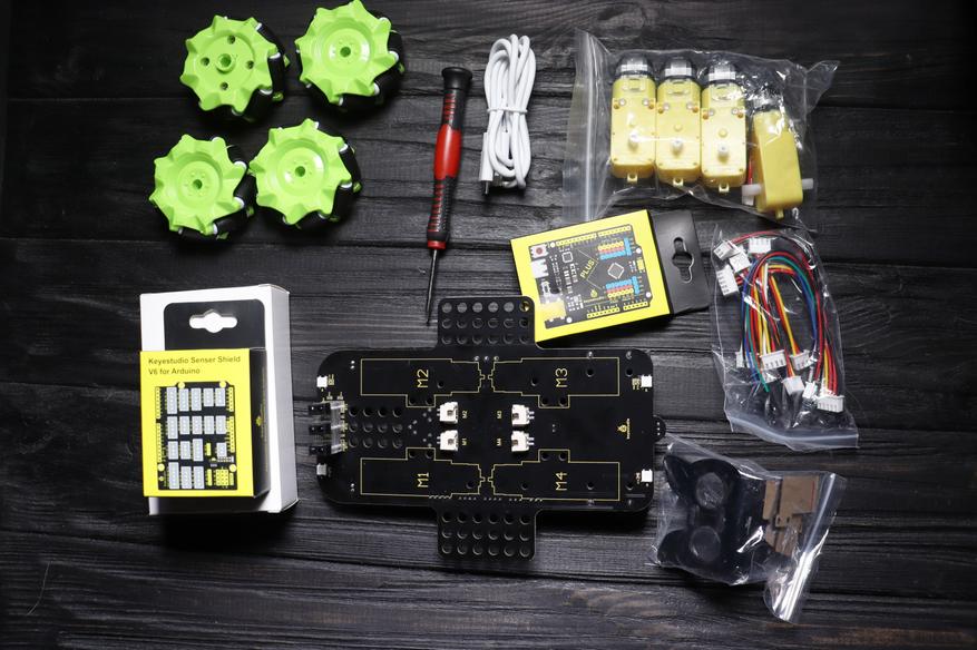
Далее будут более детально представлены основные компоненты. На основной «базе» разместились основные датчики, светодиоды, и коннекторы для подключения. Также на ней разместился аккумуляторный отсек, рассчитанный на аккумуляторы типоразмера 18650.
Основная плата выполнена очень качественно, пайка замечательная, следов от флюса нет. Данная плата является аналогом небезызвестной Arduino Uno, с некоторыми изменениями: вынесены колодки с цифровыми сигналами 3, 5, 6, 9, 10, 11 и аналоговыми А0-А5 и интерфейс подключения был изменен на Type-C.
В следующей коробке пользователя встречает плата-расширения, она же Shield. В данной модели она служит для удобного соединения всех компонентов. Как и в случае с основной платой, качество изготовления отличное.
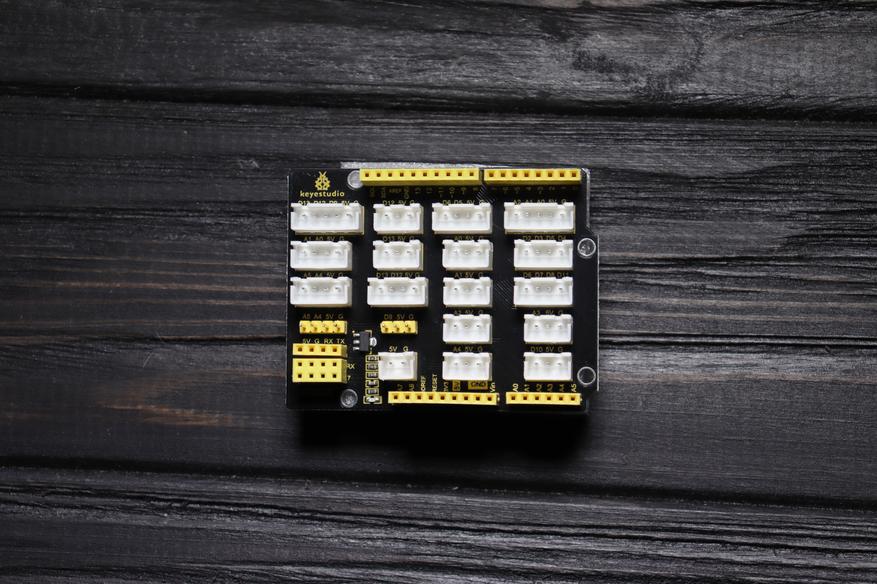
В последней коробке разместились все остальные компоненты: пульт управления, ультразвуковой датчик приближения HC-SR04, Bluetooth модуль, соединительные элементы, сервопривод и комплект винтов.
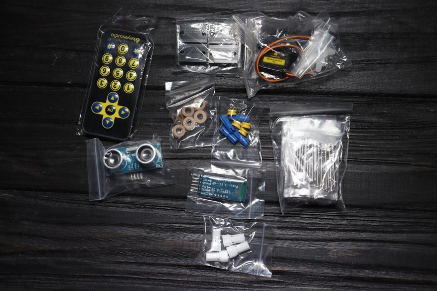
В данном разделе проведена сборка модели, а также некоторые замечания при сборке, что облегчит её. Сборка начинается с крепления ультразвукового датчика приближения на платформу.
Далее идет закрепление сервопривода на эту же платформу. Необходимо обратить внимание на то, чтобы установить сервопривод правильно, как представлено на фотографии ниже.
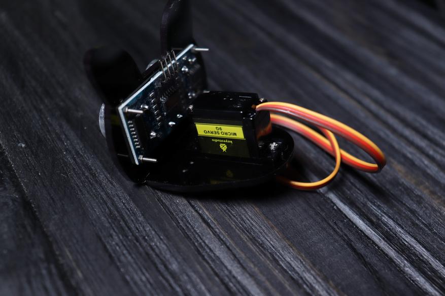
После того, как проведено закрепление всех деталей на верхнюю платформу, переходим к нижней платформе. Необходимо найти крестообразную насадку на сервопривод и 4 самореза и закрепить к платформе как показано ниже.
Обращаю внимание на то, что перед установкой сервопривода на насадку необходимо программно повернуть ровно до 90°. Делается это подобным образом: сервопривод подключается к основной плате к контактной группе D11, ВАЖНО соблюдать полярность. Оранжевый провод с сервопривода должен быть на желтой подложке, красный — на красном, черный на синем.
Стоит также не забыть подключить контроллер к компьютеру по комплектному кабелю USB Type-C и запустить среду разработки Arduino. Для корректной работы сервопривода и всех остальных компонентов рекомендую установить библиотеки производителя (ссылка ведущая на страницу с библиотеками). В панели «инструменты» должна быть выбрана плата Arduino UNO и выбран COM порт. Ввести код ниже, скомпилировать его и при отсутствии ошибок загрузить в контроллер.
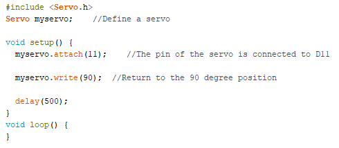
Когда сервопривод повернулся на заданный угол на его выходной вал устанавливается платформа, на которой разместилась насадка для сервопривода и закрепить это все винтом М2.
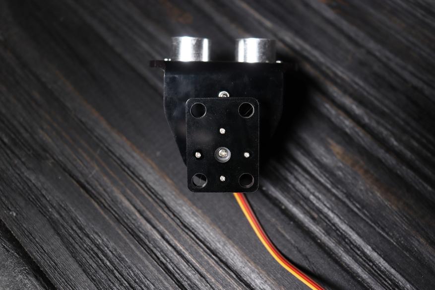
Переходим к основной базе. На 4 стойки закрепляем основной микроконтроллер и закручиваем винты с обоих сторон.
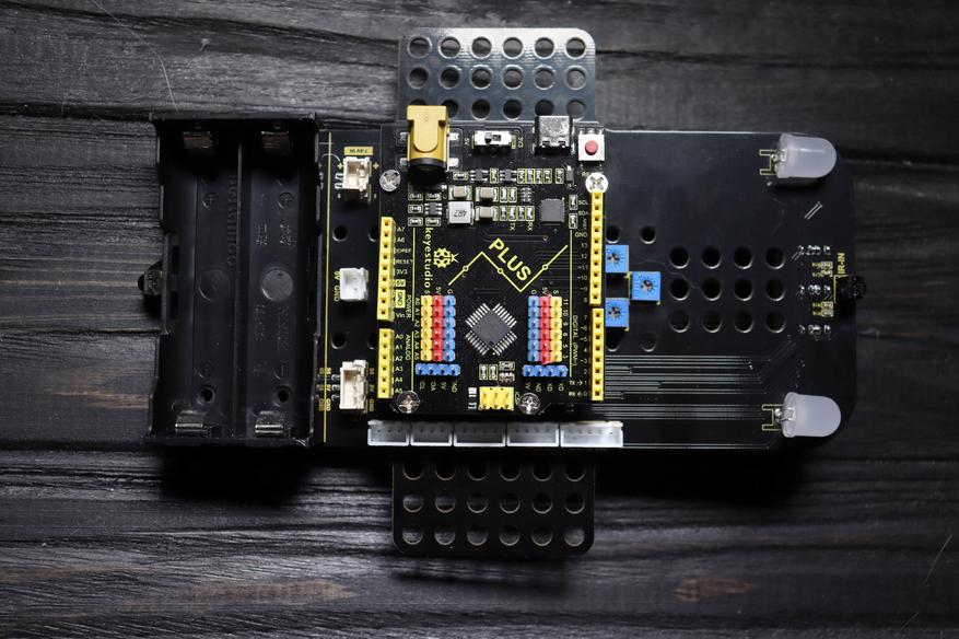
На обратной стороне проводится установка креплений под двигателя.
На установленные крепления ставятся сами двигателя и соединяются с ближайшими коннекторами.
В сами колеса устанавливаются пластиковые фиксаторы.
Далее необходимо разместить колеса в точности как показано на фотографии. Ролики должны быть направлены в разные стороны, это необходимо для корректного движения машинки.
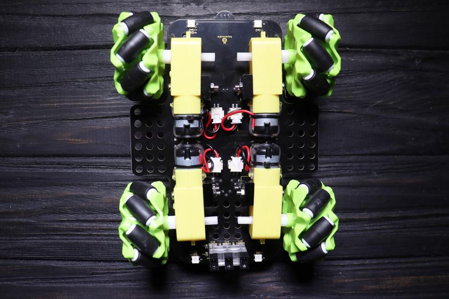
Возвращаемся к верхней стороне и к основному корпусу поворотную часть с ультразвуковым датчиком приближения и сервоприводом.
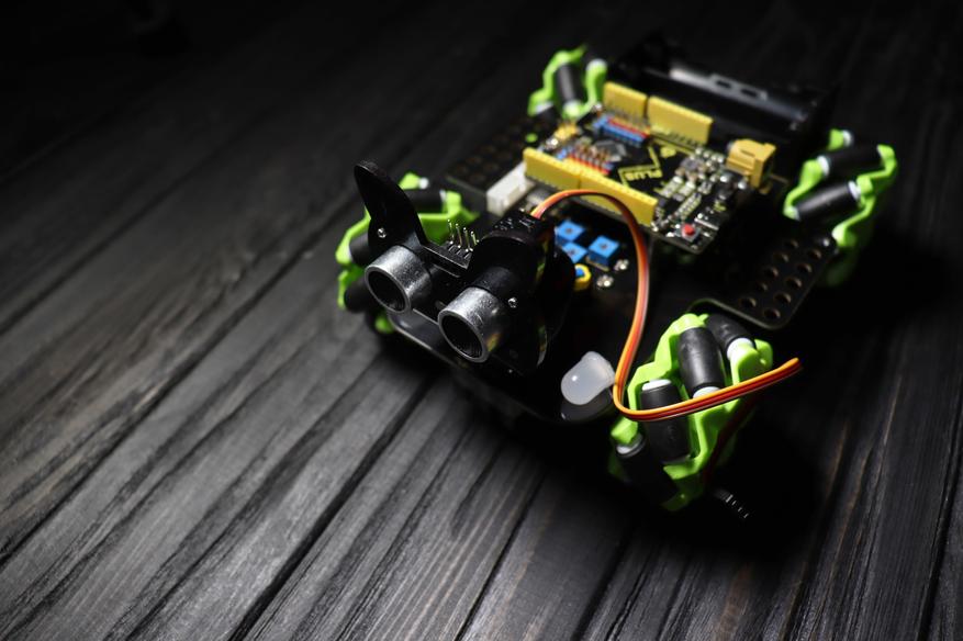
Следующим шагом будет установка платы расширения в основную плату.
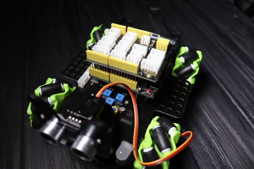
Стоит также не забыть установить модуль Bluetooth. Обращаю внимание на то, что данный модуль нужно извлекать, когда происходит загрузка кода в сам микроконтроллер, иначе будет вылазить ошибка.
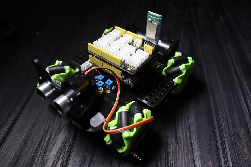
Переходим к подключению ультразвукового датчика приближения. Подключаем провода в такой очередности: VCC (питания датчика) — красный провод, Trig — синий, Echo — зеленый, Gnd — черный. Путать цвет проводов и очередность ни в коем случае нельзя, так как есть велик шанс вывести датчик из строя.
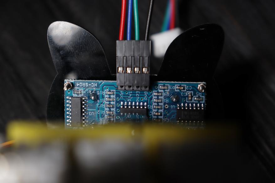
Подключаем данные провода к контактной площадке, показанной ниже на фотографии. Не забываем также подключить сервопривод
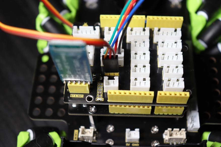
Далее подключаем все провода, согласно инструкции.
Для работы конструктора необходимо будет докупить аккумуляторы типоразмера 18650. Я использовал одни из самых емких аккумуляторов подобного формата — NCR18650 от Liitokala, являющаяся полным аналогом варианта от Panasonic, использующиеся в автомобилях Tesla.
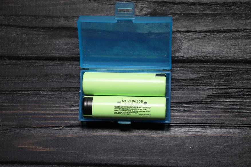
Для понимания тяжести изделия, проверил измерение весами Xiaomi ATuMan Duka ES1 без аккумуляторов (470.1) и с (565.6 грамм).
Готовая машинка имеет следующий вид:
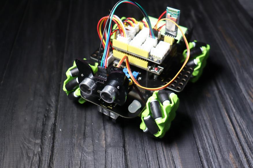
После сборки необходимо проверить на работоспособность всех подключенных датчиков. Скетчи находятся в облаке по данной ссылке. Кратко пройдусь по всем урокам:
- 1 урок — проверяет работоспособность светодиодов, размещенных на основном корпусе
- 2 урок — проделывает аналогичные действия с прошлого урока, но со светодиодами, расположенными на обратной стороне
- 3 урок — плавно поворачивает позицию сервопривода с 0 до 180 градусов, и обратно.
- 4 урок — проверяет работоспособность всех 4 двигателей
- 5 и 6 уроки — настройка и сама прошивка для движения машинки по черной линии
- 7 урок — проверка работы ультразвукового датчика приближения (в мониторе порта отображается дистанция до ближайшего объекта)
- 8 урок — машинка будет двигаться за объектом спереди, стоять или сдавать назад, расстояние можно выставить самостоятельно
- 9 урок — объезд препятствий используя ультразвуковой датчик приближения и сервопривод. Машинка «ищет» самый короткий способ объехать препятствие и объезжает его
- 10 и 11 уроки — дистанционное управление роботом через пульт
- 12 урок — дистанционное управление роботом через приложение на смартфоне. К сожалению, проверить не могу, так как смартфон наотрез отказывается подключаться к машинке.
Ниже приведен пример как машинка способна двигаться из-за своих колес. Машинка управлялась через пульт управления.
Как было и с прошлым конструктором от KEYESTUDIO, побывавшим у меня в руках, данный набор способен развлечь семью не на один вечер. К самому набору у меня практически нет замечаний: все детали замечательного качества, инструкция также подробнейшая, с пошаговой иллюстрацией (нивелирует то, что она на английском языке). Но не могу не отметить то, что к приложению смартфона у меня робот не подключился, что немного испортило исключительно положительное впечатление о данном конструкторе. Можно ли обойтись без приложения? Конечно, практически все заявленные функции работают с пульта управления, входящего в комплект. Данный набор прекрасный подарок для своего ребенка/мужа/брата/тестя/отца или девушек с техническим подходом. Конструктор даст понимание как работает программа и обучит азам программирования. Могу я рекомендовать данный набор к покупке? Конечно, я получил огромное удовольствие от процесса сборки и его настройки.
Приобрести данный набор с конструктором KEYESTUDIO KS0551 можно в официальном магазине KEYESTUDIO, а с учетом крупнейшей распродажи в этом году цена будет немного приятнее.
Дополнительно предлагаю ознакомиться с подборками похожих наборов:
- 10 программируемых электронных конструкторов с Aliexpress
- 10 электронных конструкторов на Arduino с Aliexpress
Спасибо за внимание.
В этой статье я решал собрать полное пошаговое руководство для начинающих Arduino. Мы разберем что такое ардуино, что нужно для начала изучения, где скачать и как установить и настроить среду программирования, как устроен и как пользоваться языком программирования и многое другое, что необходимо для создания полноценных сложных устройств на базе семейства этих микроконтроллеров.
Тут я постараюсь дать сжатый минимум для того, что бы вы понимали принципы работы с Arduino. Для более полного погружения в мир программируемых микроконтроллеров обратите внимание на другие разделы и статьи этого сайта. Я буду оставлять ссылки на другие материалы этого сайта для более подробного изучения некоторых аспектов.
Что такое Arduino и для чего оно нужно?
Arduino — это электронный конструктор, который позволяет любому человеку создавать разнообразные электро-механические устройства. Ардуино состоит из программной и аппаратной части. Программная часть включает в себя среду разработки (программа для написания и отладки прошивок), множество готовых и удобных библиотек, упрощенный язык программирования. Аппаратная часть включает в себя большую линейку микроконтроллеров и готовых модулей для них. Благодаря этому, работать с Arduino очень просто!
С помощью ардуино можно обучаться программированию, электротехнике и механике. Но это не просто обучающий конструктор. На его основе вы сможете сделать действительно полезные устройства.
Начиная с простых мигалок, метеостанций, систем автоматизации и заканчивая системой умного дома, ЧПУ станками и беспилотными летательными аппаратами. Возможности не ограничиваются даже вашей фантазией, потому что есть огромное количество инструкций и идей для реализации.
Стартовый набор Arduino
Для того что бы начать изучать Arduino необходимо обзавестись самой платой микроконтроллера и дополнительными деталями. Лучше всего приобрести стартовый набор Ардуино, но можно и самостоятельно подобрать все необходимое. Я советую выбрать набор, потому что это проще и зачастую дешевле. Вот ссылки на лучшие наборы и на отдельные детали, которые обязательно пригодятся вам для изучения:
| Базовый набор ардуино для начинающих: | Купить |
| Большой набор для обучения и первых проектов: | Купить |
| Набор дополнительных датчиков и модулей: | Купить |
| Ардуино Уно самая базовая и удобная модель из линейки: | Купить |
| Беспаечная макетная плата для удобного обучения и прототипирования: | Купить |
| Набор проводов с удобными коннекторами: | Купить |
| Комплект светодиодов: | Купить |
| Комплект резисторов: | Купить |
| Кнопки: | Купить |
| Потенциометры: | Купить |
Среда разработки Arduino IDE
Для написания, отладки и загрузки прошивок необходимо скачать и установить Arduino IDE. Это очень простая и удобная программа. На моем сайте я уже описывал процесс загрузки, установки и настройки среды разработки. Поэтому здесь я просто оставлю ссылки на последнюю версию программы и на статью с подробной инструкцией.
Язык программирования Ардуино
Когда у вас есть на руках плата микроконтроллера и на компьютере установлена среда разработки, вы можете приступать к написанию своих первых скетчей (прошивок). Для этого необходимо ознакомиться с языком программирования.
Для программирования Arduino используется упрощенная версия языка C++ с предопределенными функциями. Как и в других Cи-подобных языках программирования есть ряд правил написания кода. Вот самые базовые из них:
- После каждой инструкции необходимо ставить знак точки с запятой (;)
- Перед объявлением функции необходимо указать тип данных, возвращаемый функцией или void если функция не возвращает значение.
- Так же необходимо указывать тип данных перед объявлением переменной.
- Комментарии обозначаются: // Строчный и /* блочный */
Подробнее о типах данных, функциях, переменных, операторах и языковых конструкциях вы можете узнать на странице по программированию Arduino. Вам не нужно заучивать и запоминать всю эту информацию. Вы всегда можете зайти в справочник и посмотреть синтаксис той или иной функции.
Все прошивки для Arduino должны содержать минимум 2 функции. Это setup() и loop().
Функция setup
Функция setup() выполняется в самом начале и только 1 раз сразу после включения или перезагрузки вашего устройства. Обычно в этой функции декларируют режимы пинов, открывают необходимые протоколы связи, устанавливают соединения с дополнительными модулями и настраивают подключенные библиотеки. Если для вашей прошивки ничего подобного делать не нужно, то функция все равно должна быть объявлена. Вот стандартный пример функции setup():
void setup() {
	Serial.begin(9600);	// Открываем serial соединение
	pinMode(9, INPUT);	// Назначаем 9 пин входом
	pinMode(13, OUTPUT); // Назначаем 13 пин выходом
}
В этом примере просто открывается последовательный порт для связи с компьютером и пины 9 и 13 назначаются входом и выходом. Ничего сложного. Но если вам что-либо не понятно, вы всегда можете задать вопрос в комментариях ниже.
Функция loop
Функция loop() выполняется после функции setup(). Loop в переводе с английского значит «петля». Это говорит о том что функция зациклена, то есть будет выполняться снова и снова. Например микроконтроллер ATmega328, который установлен в большинстве плат Arduino, будет выполнять функцию loop около 10 000 раз в секунду (если не используются задержки и сложные вычисления). Благодаря этому у нас есть большие возможности.
Макетная плата Breadbord
Вы можете создавать простые и сложные устройства. Для удобства я советую приобрести макетную плату (Breadbord) и соединительные провода. С их помощью вам не придется паять и перепаивать провода, модули, кнопки и датчики для разных проектов и отладки. С беспаечной макетной платой разработка становится более простой, удобной и быстрой. Как работать с макетной платой я рассказывал в этом уроке. Вот список беспаечных макетных плат:
| Макетная плата на 800 точек с 2 шинами питания, платой подачи питания и проводами: | Купить |
| Большая макетная плата на 1600 точек с 4 шинами питания: | Купить |
| Макетная плата на 800 точек с 2 шинами питания: | Купить |
| Макетная плата на 400 точек с 2 шинами питания: | Купить |
| Макетная плата на 170 точек: | Купить |
| Соединительные провода 120 штук: | Купить |
Первый проект на Arduino
Давайте соберем первое устройство на базе Ардуино. Мы просто подключим тактовую кнопку и светодиод к ардуинке. Схема проекта выглядит так:
Обратите внимание на дополнительные резисторы в схеме. Один из них ограничивает ток для светодиода, а второй притягивает контакт кнопки к земле. Как это работает и зачем это нужно я объяснял в этом уроке. Для того что бы все работало, нам надо написать скетч. Давайте сделаем так, что бы светодиод загорался после нажатия на кнопку, а после следующего нажатия гас. Вот наш первый скетч: В этом скетче я создал дополнительную функцию debounse для подавления дребезга контактов. О дребезге контактов есть целый урок на моем сайте. Обязательно ознакомьтесь с этим материалом. Широтно-импульсная модуляция (ШИМ) — это процесс управления напряжением за счет скважности сигнала. То есть используя ШИМ мы можем плавно управлять нагрузкой. Например можно плавно изменять яркость светодиода, но это изменение яркости получается не за счет уменьшения напряжения, а за счет увеличения интервалов низкого сигнала. Принцип действия ШИМ показан на этой схеме: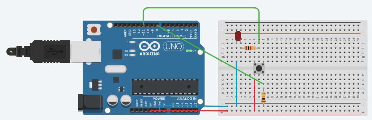
 // переменные с пинами подключенных устройств
int switchPin = 8;
int ledPin = 11;

// переменные для хранения состояния кнопки и светодиода
boolean lastButton = LOW;
boolean currentButton = LOW;
boolean ledOn = false;

void setup() {
	pinMode(switchPin, INPUT);
	pinMode(ledPin, OUTPUT);
}

// функция для подавления дребезга
boolean debounse(boolean last) {
	boolean current = digitalRead(switchPin);
	if(last != current) {
		delay(5);
		current = digitalRead(switchPin);
	}
	return current;
}

void loop() {
	currentButton = debounse(lastButton);
	if(lastButton == LOW && currentButton == HIGH) {
		ledOn = !ledOn;
	}
	lastButton = currentButton;
	digitalWrite(ledPin, ledOn);
}ШИМ Arduino
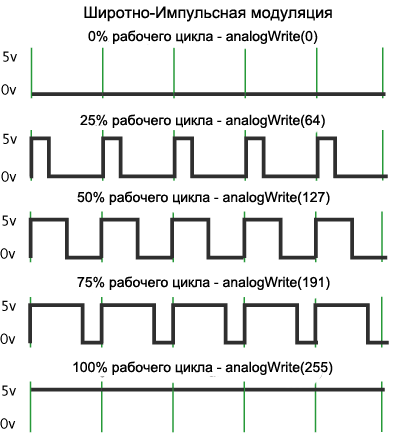
Когда мы подаем ШИМ на светодиод, то он начинает быстро зажигаться и гаснуть. Человеческий глаз не способен увидеть это, так как частота слишком высока. Но при съемке на видео вы скорее всего увидите моменты когда светодиод не горит. Это случится при условии что частота кадров камеры не будет кратна частоте ШИМ.
В Arduino есть встроенный широтно-импульсный модулятор. Использовать ШИМ можно только на тех пинах, которые поддерживаются микроконтроллером. Например Arduino Uno и Nano имеют по 6 ШИМ выводов: это пины D3, D5, D6, D9, D10 и D11. В других платах пины могут отличаться. Вы можете найти описание интересующей вас платы в этом разделе.
Для использования ШИМ в Arduino есть функция analogWrite(). Она принимает в качестве аргументов номер пина и значение ШИМ от 0 до 255. 0 — это 0% заполнения высоким сигналом, а 255 это 100%. Давайте для примера напишем простой скетч. Сделаем так, что бы светодиод плавно загорался, ждал одну секунду и так же плавно угасал и так до бесконечности. Вот пример использования этой функции:
 // Светодиод подключен к 11 пину
int ledPin = 11;

void setup() {
	pinMode(ledPin, OUTPUT);
}

void loop() {
	for (int i = 0; i < 255; i++) {
		analogWrite(ledPin, i);
		delay(5);
	}

	delay(1000);

	for (int i = 255; i > 0; i--) {
		analogWrite(ledPin, i);
		delay(5);
	}
}
Аналоговые входы Arduino
Как мы уже знаем, цифровые пины могут быть как входом так и выходом и принимать/отдавать только 2 значения: HIGH и LOW. Аналоговые пины могут только принимать сигнал. И в отличии от цифровых входов аналоговые измеряют напряжение поступающего сигнала. В большинстве плат ардуино стоит 10 битный аналогово-цифровой преобразователь. Это значит что 0 считывается как 0 а 5 В считываются как значение 1023. То есть аналоговые входы измеряют, подаваемое на них напряжение, с точностью до 0,005 вольт. Благодаря этому мы можем подключать разнообразные датчики и резисторы (терморезисторы, фоторезисторы) и считывать аналоговый сигнал с них.
Для этих целей в Ардуино есть функция analogRead(). Для примера подключим фоторезистор к ардуино и напишем простейший скетч, в котором мы будем считывать показания и отправлять их в монитор порта. Вот так выглядит наше устройство:

В схеме присутствует стягивающий резистор на 10 КОм. Он нужен для того что бы избежать наводок и помех. Теперь посмотрим на скетч:
int sensePin = 0; // Пин к которому подключен фоторезистор

void setup() {
 analogReferense(DEFAULT); // Задаем опорное значение напряжения. Эта строка не обязательна.
 Serial.begin(9600); // Открываем порт на скорости 9600 бод.
}

void loop() {
 Serial.println(analogRead(sensePin)); // Считываем значение и выводим в порт
 delay(500); // задержка для того что бы значений было не слишком много
}
Вот так из двух простейших элементов и четырех строк кода мы сделали датчик освещенности. На базе этого устройства мы можем сделать умный светильник или ночник. Очень простое и полезное устройство.
Вот мы и рассмотрели основы работы с Arduino. Теперь вы можете сделать простейшие проекты. Что бы продолжить обучение и освоить все тонкости, я советую прочитать книги по ардуино и пройти бесплатный обучающий курс. После этого вы сможете делать самые сложные проекты, которые только сможете придумать.