
1
103
36
8_
EN
G.xm
l
2
003
-06-
0
3
Subject to reasonable modifications due to technical advances.
Copyright Pepperl+Fuchs, Printed in Germany
Pepperl+Fuchs Group • Tel.: Germany +49 621 776-0 • USA +1 330 4253555 • Singapore +65 67799091 • Internet http://www.pepperl-fuchs.com
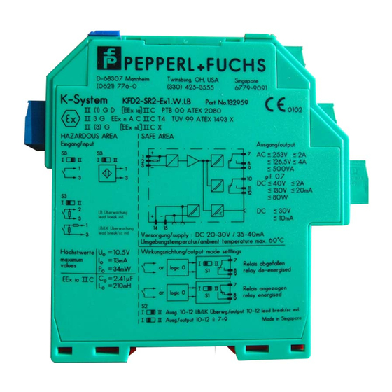
KFD2-SR2-Ex2.W
Isolated switch amplifiers
Input I EEx ia IIC
Input II EEx ia IIC
green
red
red
Output
I
Output
II
Power
Rail
LB/SC
collective
error message
Switch S3 in position I
Switch S3 in position I
Switch S3 in position I
Switch S3 in position II
Power
supply
only
KFD2-SR2-Ex2.W
LB
SC
LB
SC
Saf
e area
Hazar
dous area,
zone 0,
zone 1
yellow
yellow
without
LB, SC
without SC
1+
3-
1+
3-
1+
3-
2+
3-
2+
3-
1+
S1
S2
S3
S3
II
I
II
I
1
10 k
Ω
10 k
Ω
14 15
400
Ω ≤ R ≤ 2 kΩ
4+
6-
4+
6-
4+
6-
5+
6-
5+
6-
4+
10 k
Ω
10 k
Ω
400
Ω ≤ R ≤ 2 kΩ
7
8
9
10 11 12
+
—
+
—
&
&
Composition
24 V DC
• 2-channel
• Control circuit EEx ia IIC
• Reversible mode of operation
• 1 signal output with 1 changeover
contact per channel
• EMC acc. to NAMUR NE 21
• LB/SC monitoring
• LB/SC collective error message via
Power Rail
• Usable up to SIL 2 acc. to IEC 61508
The transformer isolated barrier
transfers digital signals from the
hazardous area. Sensors per
DIN EN 60947-5-6 (NAMUR) and
mechanical contacts may be used as
alarms. Control circuits are monitored
for lead breakage (LB) and short circuit
(SC). The external faults are indicated
according to NAMUR NE44 by a red
flashing LED. For type KFD2-SR2-
Ex2.W, an LB/SC collective error
message is in addition transferred
through the Power Rail to the power
feed module. The intrinsically safe
inputs per DIN EN 50020 are safely
isolated from the output and the power
supply. Relay outputs are galvanically
separated from the mains power in
accordance with IEC 61140. Relay
outputs are galvanically separated from
each other in accordance with
IEC 61140.
Function
Output: relay
-
Contents
-
Table of Contents
-
Bookmarks
Quick Links
Functional Safety
Switch Amplifier
KFD2-SR2-Ex*.W(.LB)
Manual
2
ISO9001
Related Manuals for Pepperl+Fuchs KFD2-SR2-Ex Series
Summary of Contents for Pepperl+Fuchs KFD2-SR2-Ex Series
-
Page 1
Functional Safety Switch Amplifier KFD2-SR2-Ex*.W(.LB) Manual ISO9001… -
Page 2
Phone: +49 621 776 — 0 E-mail: info@de.pepperl-fuchs.com North American Headquarters Pepperl+Fuchs Inc. 1600 Enterprise Parkway Twinsburg, Ohio 44087 Phone: +1 330 425-3555 E-mail: sales@us.pepperl-fuchs.com Asia Headquarters Pepperl+Fuchs Pte. Ltd. P+F Building 18 Ayer Rajah Crescent Singapore 139942 Phone: +65 6779-9091 E-mail: sales@sg.pepperl-fuchs.com https://www.pepperl-fuchs.com… -
Page 3: Table Of Contents
Functional Safety KFD2-SR2-Ex*.W(.LB) Contents Introduction …………5 Content of this Document .
-
Page 4
Functional Safety KFD2-SR2-Ex*.W(.LB) Contents… -
Page 5: Introduction
Additionally, the following parts may belong to the documentation, if applicable: • EU-type examination certificate • EU declaration of conformity • Attestation of conformity • Certificates • Control drawings • FMEDA report • Assessment report • Additional documents For more information about Pepperl+Fuchs products with functional safety, see www.pepperl-fuchs.com/sil.
-
Page 6: Safety Information
Functional Safety KFD2-SR2-Ex*.W(.LB) Introduction Safety Information Target Group, Personnel Responsibility for planning, assembly, commissioning, operation, maintenance, and dismounting lies with the plant operator. Only appropriately trained and qualified personnel may carry out mounting, installation, commissioning, operation, maintenance, and dismounting of the product. The personnel must have read and understood the instruction manual and the further documentation.
-
Page 7: Symbols Used
Functional Safety KFD2-SR2-Ex*.W(.LB) Introduction Symbols Used This document contains symbols for the identification of warning messages and of informative messages. Warning Messages You will find warning messages, whenever dangers may arise from your actions. It is mandatory that you observe these warning messages for your personal safety and in order to avoid property damage.
-
Page 8: Product Description
Product Description Product Description Validity This manual is only valid for devices with a part number greater than #203350. Contact your Pepperl+Fuchs representative for information about older devices. Function KFD2-SR2-Ex1.W This isolated barrier is used for intrinsic safety applications. The device transfers digital signals from NAMUR sensors or dry contacts from the hazardous area to the non-hazardous area.
-
Page 9: Interfaces
• Non-safety relevant interfaces: fault indication output Note For corresponding connections see datasheet. Marking Pepperl+Fuchs Group Lilienthalstraße 200, 68307 Mannheim, Germany Internet: www.pepperl-fuchs.com KFD2-SR2-Ex1.W, KFD2-SR2-Ex2.W, KFD2-SR2-Ex1.W.LB Up to SIL 2 The *-marked letters of the type code are placeholders for versions of the device.
-
Page 10: Planning
Functional Safety KFD2-SR2-Ex*.W(.LB) Planning Planning System Structure 3.1.1 Low Demand Mode of Operation If there are two control loops, one for the standard operation and another one for the functional safety, then usually the demand rate for the safety loop is assumed to be less than once per year.
-
Page 11: Assumptions
Functional Safety KFD2-SR2-Ex*.W(.LB) Planning Assumptions The following assumptions have been made during the FMEDA: • Failure rates are constant, wear is not considered. • Failure rate based on the Siemens standard SN 29500. • The safety-related device is considered to be of type A device with a hardware fault tolerance of 0.
-
Page 12: Safety Function And Safe State
Functional Safety KFD2-SR2-Ex*.W(.LB) Planning Safety Function and Safe State Safe State In the safe state of the safety function the output is de-energized. Safety Function for 1-channel Devices KFD2-SR2-Ex1.W S1 position I (normal The safe state is reached if the NAMUR sensor input operation) is in the off state.
-
Page 13
Functional Safety KFD2-SR2-Ex*.W(.LB) Planning LB/SC Diagnosis If the line fault detection is active (mandatory, see datasheet), the input loops of all device versions are supervised. The line fault detection is activated if switch S3 is in position I. The related safety function is defined as the outputs are de-energized (safe state), if there is a line fault detected. -
Page 14: Characteristic Safety Values
Functional Safety KFD2-SR2-Ex*.W(.LB) Planning Characteristic Safety Values Parameters Characteristic values Assessment type and Full assessment documentation Device type Mode of operation Low demand mode or high demand mode Safety function Output is de-energized 113 FIT 0 FIT 37.8 FIT …
-
Page 15: Useful Lifetime
Functional Safety KFD2-SR2-Ex*.W(.LB) Planning Useful Lifetime Although a constant failure rate is assumed by the probabilistic estimation this only applies provided that the useful lifetime of components is not exceeded. Beyond this useful lifetime, the result of the probabilistic estimation is meaningless as the probability of failure significantly increases with time.
-
Page 16: Mounting And Installation
Functional Safety KFD2-SR2-Ex*.W(.LB) Mounting and Installation Mounting and Installation Mounting and Installing the Device Observe the safety instructions in the instruction manual. Observe the information in the manual. Observe the requirements for the safety loop. Connect the device only to devices that are suitable for this safety application. Check the safety function to ensure the expected output behavior.
-
Page 17: Operation
Functional Safety KFD2-SR2-Ex*.W(.LB) Operation Operation Danger! Danger to life from missing safety function If the safety loop is put out of service, the safety function is no longer guaranteed. • Do not deactivate the device. • Do not bypass the safety function. •…
-
Page 18
Functional Safety KFD2-SR2-Ex*.W(.LB) Operation 5.1.1 Procedure for Manual Proof Test Equipment required: • Digital multimeter with an accuracy of 0.1 % Use for the proof test of the intrinsic safety side of the device a special digital multimeter for intrinsically safe circuits. If intrinsically safe circuits are operated with non-intrinsically safe circuits, they must no longer be used as intrinsically safe circuits. -
Page 19
Functional Safety KFD2-SR2-Ex*.W(.LB) Operation Multimeter KFD2-SR2-Ex1.W (mA) 240 :/2.5 W 24 V DC Multimeter (mA) Multimeter (mA) 24 V DC Zone 0, 1, 2 Zone 2 Power I supply Supply Div. 2 Div. 1, 2 supply Figure 5.1 Proof test set-up for KFD2-SR2-Ex1.W Multimeter KFD2-SR2-Ex1.W.LB (mA) -
Page 20
Functional Safety KFD2-SR2-Ex*.W(.LB) Operation Multimeter KFD2-SR2-Ex2.W (mA) 240 :/2.5 W 24 V DC Multimeter (mA) Multimeter (mA) 240 :/2.5 W 24 V DC Multimeter (mA) Multimeter (mA) 24 V DC Zone 0, 1, 2 Zone 2 Power I supply Supply Div. -
Page 21: Maintenance And Repair
Functional Safety KFD2-SR2-Ex*.W(.LB) Maintenance and Repair Maintenance and Repair Danger! Danger to life from missing safety function Changes to the device or a defect of the device can lead to device malfunction. The function of the device and the safety function is no longer guaranteed. Do not repair, modify, or manipulate the device.
-
Page 22: List Of Abbreviations
Functional Safety KFD2-SR2-Ex*.W(.LB) List of Abbreviations List of Abbreviations Diagnostic Coverage of dangerous faults Failure In Time in 10 Failure Mode, Effects, and Diagnostics Analysis FMEDA Probability of safe failure Probability of dangerous detected failure Probability of dangerous undetected failure …
-
Page 23
Functional Safety KFD2-SR2-Ex*.W(.LB) Notes… -
Page 24
Pepperl+Fuchs Quality Download our latest policy here: www.pepperl-fuchs.com/quality www.pepperl-fuchs.com © Pepperl+Fuchs · Subject to modifications Printed in Germany / DOCT-6656A…

|
Isolated switch amplifiers |
KFD2-SR2-Ex2.W |
|
Output: relay |
|
24 V DC
•2-channel
•Control circuit EEx ia IIC
•Reversible mode of operation
•1 signal output with 1 changeover contact per channel
•EMC acc. to NAMUR NE 21
•LB/SC monitoring
•LB/SC collective error message via Power Rail
•Usable up to SIL 2 acc. to IEC 61508
Function
The transformer isolated barrier transfers digital signals from the hazardous area. Sensors per DIN EN 60947-5-6 (NAMUR) and
mechanical contacts may be used as alarms. Control circuits are monitored for lead breakage (LB) and short circuit (SC). The external faults are indicated according to NAMUR NE44 by a red flashing LED. For type KFD2-SR2- Ex2.W, an LB/SC collective error message is in addition transferred through the Power Rail to the power feed module. The intrinsically safe inputs per DIN EN 50020 are safely isolated from the output and the power supply. Relay outputs are galvanically separated from the mains power in accordance with IEC 61140. Relay outputs are galvanically separated from each other in accordance with
IEC 61140.
|
Input I EEx ia IIC |
Input II EEx ia IIC |
||||||
|
1+ |
3- |
4+ |
6- |
||||
|
400 Ω ≤ R ≤ 2 kΩ |
400 Ω ≤ R ≤ 2 kΩ |
||||||
|
10 kΩ |
3- |
4+ |
10 kΩ |
6- |
|||
|
1+ |
|||||||
|
without SC |
10 kΩ |
5+ |
10 kΩ |
||||
|
2+ |
3- |
6- |
|||||
|
without |
|||||||
|
LB, SC 1+ |
3- |
4+ |
6- |
||||
|
1+ 2+ |
3- |
4+ 5+ |
6- |
||||
|
LB |
LB |
||||||
|
SC |
SC |
||||||
|
I |
II |
S3 |
I |
II |
S3 |
||
|
red |
|||||||
|
S1 |
S2 |
red |
|||||
|
& |
& |
||||||
|
green |
|||||||
|
yellow |
yellow |
||||||
|
7 |
8 |
9 |
10 11 12 |
||||
|
Output I |
Output II |
Composition
Subject to reasonable modifications due to technical advances.
Switch S3 in position I
Switch S3 in position I
Switch S3 in position I
zone Hazardouszone0, area,1
Switch S3 in position II
|
area |
||
|
+ — |
1 |
Safe |
+—
14 15
Power Power LB/SC supply Rail collective
error message
only KFD2-SR2-Ex2.W
103368_ENG.xml 2003-06-03
Copyright Pepperl+Fuchs, Printed in Germany
|
1 |
Pepperl+Fuchs Group • Tel.: Germany +49 621 776-0 • USA +1 330 4253555 • Singapore +65 67799091 • Internet http://www.pepperl-fuchs.com |
 Loading…
You can only view or download manuals with
Sign Up and get 5 for free
Upload your files to the site. You get 1 for each file you add
Get 1 for every time someone downloads your manual
Buy as many as you need

1
103368_GER.xml 2003-06-03
umutbare Änderungen aufgrund technischer Verbesserungen vorbehalten. Copyright Pepperl+Fuchs, Printed in Germany
Pepperl+Fuchs GmbH • 68301 Mannheim • Telefon +49 621 776-2222 • Telefax +49 621 776 272222 • Internet http://www.pepperl-fuchs.com
KFD2-SR2-Ex2.W
Trennschaltverstärker
Eingang I EEx ia IIC Eingang II EEx ia IIC
grün
rot rot
Ausgang I
Ausgang II
Power
Rail
LB-/LK-
Sammel-
meldung
Schalter S3 in Pos. I
Schalter S3 in Pos. I
Schalter S3 in Pos. I
Schalter S3 in Pos. II
Netz
nur bei
KFD2-SR2-Ex2.W
LB
LK
LB
LK
Nicht-Ex-Bereich
Ex-Bereich, Zone 0, Zone 1
gelb gelb
ohne
LB, LK
ohne LK
1+ 3-
1+ 3-
1+ 3-
2+
3-2+
3-1+
S1 S2
S3 S3
II
I
II
I
1
10 kΩ
10 kΩ
14 15
400 Ω ≤ R ≤ 2 kΩ
4+ 6-
4+ 6-
4+ 6-
5+
6-5+
6-4+
10 kΩ
10 kΩ
400 Ω ≤ R ≤ 2 kΩ
789 101112
+-
+-
&&
Aufbau
24 V DC
• 2-kanalig
• Steuerstromkreis EEx ia IIC
• Umkehrbare Wirkungsrichtung
• 1 Signalausgang mit 1 Wechsler je
Kanal
• EMV gemäß NAMUR NE 21
• LB-/LK-Überwachung
• LB-/LK-Sammelmeldung über Power
Rail
• Bis SIL 2 gemäß IEC 61508
einsetzbar
Der Trennschaltverstärker überträgt di-
gitale Signale aus dem explosionsge-
fährdeten Bereich. Signalgeber können
Sensoren nach DIN EN 60947-5-6
(NAMUR) oder mechanische Kontakte
sein. Die Steuerstromkreise werden auf
Leitungsunterbrechung (LB) und Lei-
tungskurzschluss (LK) überwacht. Die
Anzeige externer Störungen erfolgt ge-
mäß NAMUR NE44 durch eine rot blin-
kende LED. Beim Typ KFD2-SR2-
Ex2.W wird zusätzlich eine LB-/LK-
Sammelmeldung über das Power Rail
auf den Einspeisebaustein übertra-
gen. Die eigensicheren Eingänge sind
gemäß DIN EN 50020 sicher von Aus-
gang und Netz getrennt. Die Relaisaus-
gänge sind gemäß IEC 61140 sicher
vom Netz getrennt. Die Relaisausgän-
ge sind untereinander gemäß
IEC 61140 galvanisch getrennt.
Funktion
Ausgang: Relais

Instruction Manual
1. Marking
Switch amplifier
KFD2-SR2-Ex1.W, KFD2-SR2-Ex1.W.LB, KFD2-SR2-Ex2.W
ATEX certificate: PTB 00 ATEX 2080
ATEX marking:
1 II (1)G [Ex ia Ga] IIC
1 II (1)D [Ex ia Da] IIIC
1 I (M1) [Ex ia Ma] I
ATEX certificate: TÜV 99 ATEX 1493 X
ATEX marking: : 1 II 3G Ex ec nC IIC T4 Gc
IECEx certificate: IECEx PTB 11.0034 , IECEx TUN 19.0013X
IECEx marking:
[Ex ia Ga] IIC
[Ex ia Da] IIIC
[Ex ia Ma] I
Ex ec nC IIC T4 Gc
North America Certifcates: E106378 (UL)
Class I, Division 2, Groups A-D, T4
Class I, Zone 2, Group IIC T4
Associated apparatus with intrinsically safe circuits for:
Class I, Division 1, Groups A-D; Class II, Division 1, Groups E-G;
Class III
[AEx ia Ga] IIC, [AEx ia Da] IIIC, [Ex ia Ga] IIC, [Ex ia Da] IIIC
USA certificates: FM19US0207X
Class I, Division 2, Groups A-D, T4
Associated apparatus with intrinsically safe circuits for:
Class I, Division 1, Groups A-D; Class II, Division 1, Groups E-G;
Class III
Pepperl+Fuchs Group
Lilienthalstraße 200, 68307 Mannheim, Germany
Internet: www.pepperl-fuchs.com
2. Target Group, Personnel
Responsibility for planning, assembly, commissioning, operation,
maintenance, and dismounting lies with the plant operator.
The personnel must be appropriately trained and qualified in order to carry
out mounting, installation, commissioning, operation, maintenance, and
dismounting of the device. The trained and qualified personnel must have
read and understood the instruction manual.
Prior to using the product make yourself familiar with it. Read the
instruction manual carefully.
3. Reference to Further Documentation
Observe laws, standards, and directives applicable to the intended use
and the operating location.
For mining applications, observe laws, standards, and directives
applicable to the operating location.
The corresponding datasheets, manuals, declarations of conformity, EU-
type examination certificates, certificates, and control drawings if
applicable supplement this document. You can find this information under
www.pepperl-fuchs.com.
If you use the device in safety-related applications, observe the
requirements for functional safety. You can find these requirements in the
functional safety documentation under www.pepperl-fuchs.com.
4. Intended Use
The device is only approved for appropriate and intended use. Ignoring
these instructions will void any warranty and absolve the manufacturer
from any liability.
The device is used in control and instrumentation technology
(C&I technology) for the galvanic isolation of signals such as 20 mA and
10 V standard signals or alternatively for adapting or standardizing signals.
The device has intrinsically safe circuits that are used for operating
intrinsically safe field devices in hazardous areas.
The device transfers digital signals from NAMUR sensors or dry contacts
from the hazardous area to the non-hazardous area.
Use the device only within the specified ambient and operating conditions.
Only use the device stationary.
The device is an associated apparatus according to IEC/EN 60079-11.
The device may be installed in the non-hazardous area.
The device is an electrical apparatus for hazardous areas of Zone 2.
If you use the device in safety-related applications, observe the
information for safety function and safe state.
5. Improper Use
Protection of the personnel and the plant is not ensured if the device is not
used according to its intended use.
6. Mounting and Installation
Do not mount a damaged or polluted device.
The device is designed for mounting on a 35 mm DIN mounting rail
according to EN 60715.
Mount the device in a way that the device is protected against mechanical
hazard. Mount the device in a surrounding enclosure for example.
The device fulfills a degree of protection IP20 according to IEC/EN 60529.
The device must be installed and operated only in a controlled
environment that ensures a pollution degree 2 (or better) according to
IEC/EN 60664-1.
If used in areas with higher pollution degree, the device needs to be
protected accordingly.
Do not mount the device in the dust hazardous area.
The device must be installed and operated only in an environment of
overvoltage category II (or better) according to IEC/EN 60664-1.
Supply the device with a power supply that meets the requirements for
safety extra-low voltage (SELV) or protective extra-low voltage (PELV).
If you are using the Power Rail, supply the Power Rail only via the
corresponding power feed modules or power supplies. Do not supply the
Power Rail via isolators.
Observe the installation instructions according to IEC/EN 60079-14.
If you install the device in safety-related applications, observe the
requirements for functional safety.
Requirements for Cables and Connection Lines
Observe the permissible core cross section of the conductor.
When using stranded conductors, crimp wire end ferrules on the
conductor ends.
Use only one conductor per terminal.
When installing the conductors the insulation must reach up to the
terminal.
Use conductors with a rated temperature suitable for the application.
If you use the device in an ambient temperature above 60 °C, use
conductors rated for a temperature of at least 80 °C.
Observe the tightening torque of the terminal screws.
Requirements for Usage as Associated Apparatus
If circuits with type of protection Ex i are operated with non-intrinsically
safe circuits, they must no longer be used as circuits with type of
protection Ex i.
Keep the separation distances between all non-intrinsically safe circuits
and intrinsically safe circuits according to IEC/EN 60079-14.
Observe the compliance of the separation distances between two
adjacent intrinsically safe circuits according to IEC/EN 60079-14.
Observe the respective peak values of the field device and the associated
apparatus with regard to explosion protection when connecting intrinsically
safe field devices with intrinsically safe circuits of associated apparatus
(verification of intrinsic safety). Also observe IEC/EN 60079-14 and
IEC/EN 60079-25.
Requirements for Equipment Protection Level Gc
The device must be installed and operated only in surrounding enclosures
that
l
comply with the requirements for surrounding enclosures according to
IEC/EN 60079-0,
l
are rated with the degree of protection IP54 according to
IEC/EN 60529.
Ensure that the surrounding enclosure can only be opened with a tool.
Connection or disconnection of energized non-intrinsically safe circuits is
only permitted in the absence of a potentially explosive atmosphere.
7. Operation, Maintenance, Repair
If you operate the device in safety-related applications, observe the
requirements for functional safety. For the proof test, plan appropriate
intervals for the operation in low demand mode.
Do not use a damaged or polluted device.
Do not repair, modify, or manipulate the device.
If there is a defect, always replace the device with an original device.
Requirements for Equipment Protection Level Gc
Connection or disconnection of energized non-intrinsically safe circuits is
only permitted in the absence of a potentially explosive atmosphere.
Only use operating elements in the absence of a potentially explosive
atmosphere.
8. Delivery, Transport, Disposal
Check the packaging and contents for damage.
Check if you have received every item and if the items received are the
ones you ordered.
DOCT-6724 / 2020-03 1 / 2