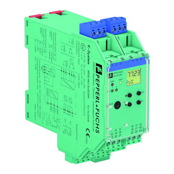
Преобразователь частоты PEPPERL FUCHS KFD2-UFC-Ex1.D со значениями срабатывания

Преобразователь частоты со значениями срабатывания
KFD2-UFC-Ex1.D
- 1-канальный изолированный барьер
- 24 V Источник постоянного тока (шина питания)
- Вход для НАМУР датчики или сухие контакты
- Входная частота 1 МГц … 5 кГц
- Токовый выход 0/4 мА … 20 мА
- Контакт реле и транзисторный выход
- Пуск в эксплуатацию переопределение
- Неисправность линии обнаружение (LFD)
- До уровня полноты безопасности 2 согл. по МЭК 61508/МЭК 61511
Функция
- Этот изолированный барьер используется для обеспечения искробезопасности.
- Устройство представляет собой универсальный преобразователь частоты, преобразующий цифровой входной сигнал в пропорциональный свободно регулируемый аналоговый выходной сигнал 0/4 мА … 20 мА и функционирующий как переключатель. ampподъемник и аварийная сигнализация.
- Функции релейных выходов (2 релейных выхода и 1 беспотенциальный транзисторный выход) легко настраиваются [отображение значения срабатывания (аварийный сигнал мин./макс.), последовательно переключаемый выход, выход делителя импульсов, выход сигнала ошибки].
- Устройство легко настраивается с помощью клавиатуры или с помощью конфигурационного программного обеспечения PACTware.
- Неисправность сигнализируется светодиодами в соотв. на NAMUR NE44 и отдельный общий вывод сообщений об ошибках.
- Дополнительную информацию см. в руководстве и www.pepperl-fuchs.com.
Подключения

Технические данные
| Общие технические условия | ||
| Тип сигнала Цифровой вход | ||
| Параметры, связанные с функциональной безопасностью | ||
| Уровень полноты безопасности (SIL) SIL 2 | ||
| Поставлять | ||
| Соединительные клеммы 23+, 24- или модуль питания/шина питания | ||
| Номинальный объемtage | Ur | 20 … 30 В постоянного тока |
| Номинальный ток | Ir | ок. 100 мА |
| Рассеиваемая мощность/потребляемая мощность | ≤ 2 Вт / 2.2 Вт |
| Интерфейс | ||
| Интерфейс программирования | разъем для программирования | |
| вход | ||
| Сторона подключения | сторона поля | |
| Подключения | Вход I: искробезопасный: клеммы 1+, 3-
Вход II: неискробезопасный: клеммы 13+, 14- |
|
| Датчик входа I в соотв. EN 60947-5-6 (NAMUR) или механический контакт | ||
| Длительность импульса > 50 мкс | ||
| Входная частота | 0.001… 5000 Гц | |
| Обнаружение неисправности линии | обрыв I ≤ 0.15 мА; I короткого замыкания > 6.5 мА | |
| Коррекция запуска входа II: 1 … 1000 с, настраивается с шагом 1 с | ||
| Активный/пассивный I > 4 мА (мин. 100 мс) / I < 1.5 мА | ||
| Обрыв цепи voltage/ток короткого замыкания | 18 В / 5 мА | |
| Результат | ||
| Сторона подключения | контрольная сторона | |
| Подключения | выход I: клеммы 10, 11, 12
выход II: клеммы 16, 17, 18 выход III: терминалы 19+, 20- выход IV: клеммы 8+, 7- |
|
| Выход I, сигнал II, реле | ||
| Контактная нагрузка 253 В перем. тока / 2 А / cos φ ≥ 0.7; 40 В постоянного тока / 2 А | ||
| Механическая жизнь | 5 х 107 циклов переключения | |
| Задержка включения/выключения | ок. 20 мс / прибл. 20 мс | |
| Выход III электронный выход, пассивный | ||
| Контактная нагрузка 40 В пост. тока | ||
| Уровень сигнала | 1-сигнал: (L+) – 2.5 В (50 мА, защита от короткого замыкания/перегрузки) 0-сигнал: выключен (ток в выключенном состоянии ≤ 10 мкА) | |
| Выход IV | аналоговый | |
| Диапазон тока 0 … 20 мА или 4 … 20 мА | ||
| Объем открытой петлиtagе макс. 24 В постоянного тока | ||
| нагрузка | Максимум. 650 Ом | |
| Сигнал неисправности | нижний предел I ≤ 3.6 мА, верхний предел ≥ 21.5 мА (согласно NAMUR NE43) | |
| Общее сообщение об ошибке Power Rail | ||
| Характеристики передачи | ||
| Вход I | ||
| Диапазон измерений | 0.001… 5000 Гц | |
| Разрешение 0.1 % значения измерения, ≥ 0.001 Гц | ||
| Точность 0.1 % от значения измерения, > 0.001 Гц | ||
| Время измерения | <100 мс | |
| Влияние температуры окружающей среды | 0.003 %/К (30 частей на миллион) | |
| Выход I, II | ||
| Задержка ответа ≤ 200 мс | ||
| Выход IV | ||
| Постановления | <10 мкА | |
| Точность < 20 мкА | ||
| Влияние температуры окружающей среды 0.005 %/K (50 ppm) | ||
| Гальваническая развязка | ||
| Входные I/другие цепи с усиленной изоляцией в соответствии с IEC/EN 61010-1, номинальный объем изоляцииtagе 300 Вэфф | ||
| Выход I, II/другие цепи | усиленная изоляция в соответствии с IEC/EN 61010-1, номинальный объем изоляцииtagе 300 Вэфф | |
| Взаимный выход I, II, III | усиленная изоляция в соответствии с IEC/EN 61010-1, номинальный объем изоляцииtagе 300 Вэфф | |
| Выход III/электропитание и общая ошибка, базовая изоляция в соответствии с IEC/EN 61010-1, номинальный объем изоляцииtagе 50 Вэфф | ||
| Выход III/блокировка при пуске базовая изоляция в соответствии с IEC/EN 61010-1, номинальная мощность изоляцииtagе 50 Вэфф | ||
| Выход III/IV | основная изоляция в соответствии с IEC/EN 61010-1, номинальный объем изоляцииtagе 50 Вэфф | |
| Выход IV/питание и коллективная ошибка | функциональная изоляция в соотв. IEC 62103, номинальный объем изоляцииtagе 50 Вэфф |
| Коррекция запуска/питание и коллективная ошибка | функциональная изоляция в соотв. IEC 62103, номинальный объем изоляцииtagе 50 Вэфф | |
| Интерфейс/питание и общая ошибка | функциональная изоляция в соотв. IEC 62103, номинальный объем изоляцииtagе 50 Вэфф | |
| Интерфейс/выход III базовая изоляция в соответствии с IEC/EN 61010-1, номинальный объем изоляцииtagе 50 Вэфф | ||
| Индикаторы/настройки | ||
| Элементы дисплея | светодиоды, дисплей | |
| Элементы управления | Панель управления | |
| Конфигурация с помощью кнопок управления
через PACTware |
||
| Место для маркировки спереди | ||
| Соответствие директиве | ||
| Электромагнитная совместимость | ||
| Директива 2014 / 30 / EU | EN 61326-1:2013 (промышленные помещения) | |
| Низкая громкостьtage | ||
| Директива 2014/35/ЕС EN 61010-1:2010 | ||
| Соответствие | ||
| Электромагнитная совместимость | СВ 21:2006 | |
| Степень защиты | IEC 60529: 2001 | |
| Вход EN 60947-5-6:2000 | ||
| Условия окружающей среды | ||
| Температура окружающей среды | -20… 60 ° C (-4… 140 ° F) | |
| Механические характеристики | ||
| Степень защиты | IP20 | |
| Подключения | винтовые клеммы | |
| Масса 300 г | ||
| Размеры 40 x 119 x 115 мм (1.6 x 4.7 x 4.5 дюйма) (Ш x В x Г), тип корпуса C2 | ||
| Исполнение | на DIN-рейку 35 мм в соотв. EN 60715:2001 | |
| Данные для применения во взрывоопасных зонах | ||
| Сертификат экспертизы типа ЕС | TUV 99 ATEX 1471 | |
| маркировка | 1 II (1)G [Ex ia Ga] IIC
1 II (1)D [Ex ia Da] IIIC 1 I (M1) [Ex ia Ma] I |
|
| Поставлять | ||
| Максимальный безопасный объемtagЕвропаm 40 В постоянного тока (Внимание! Um нет номинального объемаtagе.) | ||
| Вход I | клеммы 1+, 3-: Ex ia | |
| VoltagЕСo | 10.1 V | |
| Текущий яo 13.5 мА | ||
| Мощность Po 34 мВт (линейная характеристика) | ||
| Вход II | клеммы 13+, 14- неискробезопасные | |
| Максимальный безопасный объемtagЕСm | 40 В (Внимание! Номинальнаяtagе может быть ниже.) | |
| Выход I, II клеммы 10, 11, 12; 16, 17, 18 неискробезопасные | ||
| Максимальный безопасный объемtagЕвропаm 253 В (Внимание! Номинальнаяtagе может быть ниже.) | ||
| Контактная загрузка | 253 В перем. тока/2 А/cos φ > 0.7; 40 В пост. тока/2 А резистивная нагрузка | |
| Выход III | клеммы 19+, 20- неискробезопасные | |
| Максимальный безопасный объемtagЕСm Um 40 В (Внимание! Um нет номинального объемаtagе.) | ||
| Клеммы выхода IV 8+, 7- неискробезопасные | ||
| Максимальный безопасный объемtage | Um | 40 В постоянного тока (Внимание! Um нет номинального объемаtagе.) |
| Интерфейс | RS 232 | |
| Максимальный безопасный объемtagЕвропаm 40 В (Внимание! Um нет номинального объемаtagе.) | ||
| Сертификат TÜV 02 ATEX 1885 X | ||
| маркировка | 1 II 3G Ex nA nC IIC T4 Gc | |
| Выход I, II | ||
| Нагрузка на контакт 50 В перем. тока/2 А/cos φ > 0.7; 40 В пост. тока/2 А резистивная нагрузка | ||
| Гальваническая развязка |
| Входные/другие цепи | безопасная электрическая изоляция в соотв. IEC/EN 60079-11, томtage пиковое значение 375 В | |
| Соответствие директиве | ||
| Директива 2014/34/ЕС EN 60079-0:2012+A11:2013, EN 60079-11:2012, EN 60079-15:2010 | ||
| Международные сертификаты | ||
| Утверждение FM | ||
| Контрольный рисунок | 16-538ФМ-12 | |
| Сертификат UL E223772 | ||
| Сертификат IECEx | ||
| Сертификат IECEx | IECEx TUN 04.0007 IECEx TSA 18.0007X | |
| Маркировка IECEx | [Ex ia Ga] IIC, [Ex ia Da] IIIC, [Ex ia Ma] I Ex ec nC IIC T4 Gc | |
| Общая информация | ||
| Дополнительная информация Соблюдайте требования сертификатов, деклараций о соответствии, руководств по эксплуатации и руководств, где это применимо. Для получения информации см. www.pepperl-fuchs.com. |
сборка

Соответствие компонентов системы


Аксессуары 

Характеристическая кривая
Максимальная мощность переключения выходных контактов
См. «Общие примечания, касающиеся информации о продуктах Pepperl+Fuchs».
- Группа компаний Pepperl+Fuchs www.pepperl-fuchs.com
- США: +1 330 486 0002 pa-info@us.pepperl-fuchs.com
- Германия: +49 621 776 2222 pa-info@de.pepperl-fuchs.com
- Сингапур: +65 6779 9091 pa-info@sg.pepperl-fuchs.com
- Дата выпуска: 2022-01-10
- Дата выдачи: 2022-01-10
Документы / Ресурсы
Производитель: Pepperl+Fuchs
Маркировка: KFD2-UFC-Ex1.D | 231194
Блок контроля частоты вращения. Монтаж на DIN-рейку. Питание: 24 V DC. Вход: NAMUR. Выход: реле 2 А + 4…20 мА / 0…20 мА. Диапазон контроля: 1…5000 Гц. Температурный диапазон эксплуатации: -20…+60 °C.
Блок Pepperl+Fuchs KFD2-UFC-Ex1.D артикул 231194 предназначен для контроля частоты вращения или скорости линейного перемещения во взрывоопасных зонах в соответствии с сертификатом. Принимая сигнал от датчика приближения, например, индуктивного с выходом Namur, прибор измеряет интервал импульсов, вычисляет входную частоту и формирует линейный аналоговый сигнал 4-20 мА на выходе. Так же возможен контроль порогового значения, при достижении которого, коммутируется выходное реле. На корпусе имеются кнопки и дисплей для удобства настройки параметров. Блок контроля частоты KFD2-UFC-Ex1.D имеет входное напряжение 24 В DC. Возможность настройки на ПК через USB-адаптер K-ADP-USB, который заказывается дополнительно. Монтаж на DIN-рейку.

Цена распродажи
62468.00 ₽*
Цена розничная
95540.00 ₽
* Цена действительна при условии выставления счёта от организации, работающей на УСН.
Внимание! Актуальные цены будут указаны в выставленном счете или КП.
Условия доставки
Доставка заказа от 250 рублей*
*Весом до 1 кг, до пункта выдачи курьерской службы в г. Москва
- Доставка по всей России до двери или в пункт выдачи
- Ежедневная отправка заказов курьерскими службами
- Бесплатная доставка до терминалов ТК два раза в неделю
- Самовывоза нет
- Документы

Input II: non-intrinsically safe: terminals 13+, 14-
output II: terminals 16, 17, 18
outout III: terminasl 19+, 20-
output IV: terminals 8+, 7-
0-signal: switched off (off-state current ≤ 10 µA)
via PACTware
 II (1)G [Ex ia Ga] IIC II (1)D [Ex ia Da] IIIC I (M1) [Ex ia Ma] I II 3G Ex nA nC IIC T4 Gc
IECEx TSA 18.0007X
Ex ec nC IIC T4 Gc
Hide thumbs
Also See for KFD2-HLC-Ex1.D Series:
- Manual (44 pages)
- Manual (64 pages)
,
-
Contents
-
Table of Contents
-
Bookmarks
Quick Links
PROCESS AUTOMATION
MANUAL
HART Loop Converter
KFD2-HLC-Ex1.D(.**)
ISO9001
Related Manuals for Pepperl+Fuchs KFD2-HLC-Ex1.D Series
Summary of Contents for Pepperl+Fuchs KFD2-HLC-Ex1.D Series
-
Page 1
PROCESS AUTOMATION MANUAL HART Loop Converter KFD2-HLC-Ex1.D(.**) ISO9001… -
Page 2
HART Loop Converter KFD2-HLC-Ex1.D(.**) With regard to the supply of products, the current issue of the following document is applicable: The General Terms of Delivery for Products and Services of the Electrical Industry, published by the Central Association of the Electrical Industry (Zentralverband Elektrotechnik und Elektroindustrie (ZVEI) e.V.) in its most recent version as well as the supplementary clause: «Expanded reservation of proprietorship»… -
Page 3: Table Of Contents
HART Loop Converter KFD2-HLC-Ex1.D(.**) Content Safety ……….. 3 1.1 Validity .
-
Page 4
HART Loop Converter KFD2-HLC-Ex1.D(.**) Content Operation ……….47 4.1 Indicators during Operation . -
Page 5: Safety
HART Loop Converter KFD2-HLC-Ex1.D(.**) Safety Safety Validity The chapter “Safety” is valid as instruction manual. Specific processes and instructions in this document require special precautions to guarantee the safety of the operating personnel. Symbols used This document contains information that you must read for your own personal safety and to avoid property damage.
-
Page 6: Target Group/Personnel
HART Loop Converter KFD2-HLC-Ex1.D(.**) Safety Informative symbols Note! This symbol brings important information to your attention. Action This symbol indicates a paragraph with instructions. Target Group/Personnel The plant owner is responsible for its planning, installation, commissioning, operation, maintenance and disassembly. Mounting, installation, commissioning, operation, maintenance and disassembly of any devices may only be carried out by trained, qualified personnel.
-
Page 7: Reference To Further Documentation
KFD2-HLC-Ex1.D.4S BASEEFA 07 ATEX 0174 , for additional certifications, see www.pepperl-fuchs.com E II (1)GD [Ex ia] IIC, [Ex iaD] Pepperl+Fuchs Statement of Conformity E II 3G Ex nA II T4 X Intended Use The devices are only approved for appropriate and intended use. Ignoring these instructions will void any warranty and absolve the manufacturer from any liability.
-
Page 8: Improper Use
HART Loop Converter KFD2-HLC-Ex1.D(.**) Safety Improper Use Protection of the operating personnel and the overall system is not ensured if the product is not being used according to its intended purpose. The equipment is not suitable for isolating signals in high current applications unless this is noted separately in the corresponding datasheet.
-
Page 9: Operation, Maintenance, Repair
HART Loop Converter KFD2-HLC-Ex1.D(.**) Safety The respective peak values of the field device and the associated apparatus with regard to explosion protection should be considered when connecting intrinsically safe field devices with intrinsically safe circuits of associated apparatus (verification of intrinsic safety). Make sure to observe IEC/EN 60079-14 and IEC/EN 60079-25.
-
Page 10: Product Specifications
HART Loop Converter KFD2-HLC-Ex1.D(.**) Product Specifications Product Specifications Function The HART Loop Converter is an isolated barrier suitable for intrinsically safe applications. The device supplies field devices and can be connected in parallel to existing HART circuits. The device analyzes up to four HART variables (PV, SV, TV, QV). Three HART variables can be transformed into varying current signals from these four HART variables.
-
Page 11: Assembly
HART Loop Converter KFD2-HLC-Ex1.D(.**) Product Specifications Assembly Operating and indicating elements KFD2-HLC- Ex1.D.4S RS232 Figure 2.1 Example front view KFD2-HLC-Ex1D.4S EN — 9…
-
Page 12
HART Loop Converter KFD2-HLC-Ex1.D(.**) Product Specifications Removable terminals, blue LC display Display for showing • the measured values • the current output values • the fault messages • the parameterization mode Keypad Four keys for selecting the displayed values, the current output values and for setting the parameters of the device … -
Page 13: Dimensions
HART Loop Converter KFD2-HLC-Ex1.D(.**) Product Specifications Dimensions Housing Type C2 40 mm (1.6″) 115 mm (4.5») Figure 2.2 Number of terminal blocks max. 10 • Dimension drawing with screw terminals • When using screw terminals with test sockets the device is 124 mm (4.9 in) in height. •…
-
Page 14: Installation
HART Loop Converter KFD2-HLC-Ex1.D(.**) Installation Installation DIN Mounting Rail The devices are mounted on a 35 mm DIN mounting rail according to EN 60715. Figure 3.1 Example: DIN mounting rail UPR-MR (35 mm x 15 mm) Power Rail To reduce wiring and installation costs, Power Rail is the optimum solution. The Power Rail is a DIN mounting rail with plastic insert, that delivers power to the devices (24 V DC) and transfers bus signals and a collective error message.
-
Page 15
HART Loop Converter KFD2-HLC-Ex1.D(.**) Installation Power Rail is available in two versions: • Power Rail UPR-03 Version with three leads: • two conductors for power • one conductor for collective error messaging • Power Rail UPR-05 (only for KFD2-WAC2-(Ex)1.D) Version with five leads: •… -
Page 16: Mounting
HART Loop Converter KFD2-HLC-Ex1.D(.**) Installation Mounting Mounting the Isolated Barrier Snap the device onto the DIN mounting rail in a vertical downward movement. See figure below. CORRECT: Device snapped on vertically. INCORRECT: Device snapped on from the side. Can damage the contacts and cause the device to fail. Figure 3.3 Mounting the Terminal Blocks The insulation of the removable terminal blocks protect against direct contact.
-
Page 17: Connection
HART Loop Converter KFD2-HLC-Ex1.D(.**) Installation Connection The removable terminal blocks simplify connection and control cabinet construction significantly. These terminal blocks offer adequate space for the connection of leads with core cross-sections of up to 2.5 mm² (14 AWG). The terminal blocks are coded with red coding pins so misconnection of terminal blocks are eliminated.
-
Page 18
HART Loop Converter KFD2-HLC-Ex1.D(.**) Installation HART 250 Ω 24 V DC Zone 0, 1, 2 Power Rail Div. 1, 2 Figure 3.4 16 — EN… -
Page 19
HART Loop Converter KFD2-HLC-Ex1.D(.**) Installation 3.4.2 Output Connection (drive circuit) Connecting the Drive Circuit Connect the drive circuit to the green terminals. Note the tightening torque of the terminal screws. The tightening torque is 0.5 Nm … 0.6 Nm. Connection KFD2-HLC-Ex1.D The following connections are available: •… -
Page 20
HART Loop Converter KFD2-HLC-Ex1.D(.**) Installation Connection KFD2-HLC-Ex1.D.2W The following connections are available: • Terminals 10 … 12: output I (relay 1 (change-over contact)) • Terminals 16 … 18: output II (relay 2 (change-over contact)) • Terminals 7 … 9: output III, current output as source (7/8) or sink (7/9) •… -
Page 21
HART Loop Converter KFD2-HLC-Ex1.D(.**) Installation Connection KFD2-HLC-Ex1.D.4S The following connections are available: • Terminals 10/11: output I (relay 1 (NO contact)) • Terminals 11/12: output II (relay 2 (NO contact)) • Terminals 16/17: output III (relay 3 (NO contact)) • Terminals 17/18: output IV (relay 4 (NO contact)) •… -
Page 22
HART Loop Converter KFD2-HLC-Ex1.D(.**) Installation 3.4.3 Connecting a HART Handheld to the Field Device You have two options for connecting a HART handheld to the field device: • Connection to terminals 22/24 of the isolated barrier, see chapter 3.4.2 • Connection to the field cables from the isolated barrier to the field device Danger! Risk of explosion… -
Page 23
HART Loop Converter KFD2-HLC-Ex1.D(.**) Installation Polling Mode (command and answer) The isolated barrier deactivates the burst configuration of the field device. The isolated barrier performs the field device query using HART command 3. See chapter 3.5.6. Procedure to Restore Burst Mode If the isolated barrier does not receive any more data from the field device in burst mode, the following actions are taken: •… -
Page 24: Configuration
HART Loop Converter KFD2-HLC-Ex1.D(.**) Installation Configuration Caution! Fault in the plant Changing the device data changes the device function. Before entering new device data, make sure the plant is not endangered by changing the device data. Configuring the Device Configure the device using the buttons on the front side. Use the , , ESC, and OK buttons for navigation.
-
Page 25
HART Loop Converter KFD2-HLC-Ex1.D(.**) Installation 3.5.1 Parameterization Mode After being switched on, the device is in display mode. If you have password protection enabled, you must enter the password every time you transition from display mode to parameterization mode. Main menu parameterization mode OK + ESC (simultaneously for 1 s) →… -
Page 26
HART Loop Converter KFD2-HLC-Ex1.D(.**) Installation 3.5.2 Password Protection You can activate password protection to protect parameterization from unauthorized changes. If password protection is enabled, you can view the parameter settings but not change them. Password protection is deactivated during delivery. The password is preset and cannot be changed by the operator. -
Page 27
HART Loop Converter KFD2-HLC-Ex1.D(.**) Installation 3.5.3 Entering Numbers At the lowest menu level of the Parameter menu, you have the option of selecting or entering a numerical value. OK → Parameter Current value, flashing ← ESC ▼ ▲ ↓ New value, flashing, not stored ←… -
Page 28
HART Loop Converter KFD2-HLC-Ex1.D(.**) Installation 3.5.4 Entering Floating Point Figures At the lowest menu level of the Parameter menu, you have the option of entering floating point figures. The floating point figures can have the following structure: Positive number Input Negative number Input 43210000… -
Page 29
HART Loop Converter KFD2-HLC-Ex1.D(.**) Installation Entering a Numerical Value Select the parameter for which you want to enter the numerical value. Press the OK button. The current value from the mantissa and exponent flashes. Press the OK button. With positive numbers, the first digit of the mantissa flashes. With negative numbers, the minus sign flashes. -
Page 30
HART Loop Converter KFD2-HLC-Ex1.D(.**) Installation 3.5.5 Unit At the lowest menu level of the Unit menu, you have the option of selecting the unit type for the HART variables. • auto The device displays the unit which is transferred from connected HART field devices for the HART variables PV, SV, TV, QV. -
Page 31
HART Loop Converter KFD2-HLC-Ex1.D(.**) Installation Changing the Custom Tag of HART Variables Select the HART variable for which you would like to change the custom tag. Press the OK button. Select the Custom Tag menu. The device displays: if a value has not been defined: the insert mark and the symbol If a value is defined: the insert mark on the first character, the following character, and the symbol … -
Page 32
HART Loop Converter KFD2-HLC-Ex1.D(.**) Installation 3.5.6 HARTcom The HARTcom menu offers the option of specifying the method for communication between device and field device. If available, the device activates burst mode of the HART field device for the fastest possible communication. To query variables (PV, SV, TV, QV, if present) the device uses the universal HART command 3. -
Page 33
HART Loop Converter KFD2-HLC-Ex1.D(.**) Installation Selecting a Mode The device functions as primary or secondary HART master according to the HART standard. The device is compatible with each HART handheld and for every other HART master. Use the or buttons to select whether the device should operate as a primary or secondary HART master. -
Page 34
HART Loop Converter KFD2-HLC-Ex1.D(.**) Installation Note! Note that the field device can be put into burst mode, in accordance to the isolated barrier configuration. This also applies when a different HART master is in the HART circuit. If a different HART master changes the burst configuration of the field device, the isolated barrier waits until the other HART master logs out of the HART circuit. -
Page 35
HART Loop Converter KFD2-HLC-Ex1.D(.**) Installation Activating Rebuild If the connection to the field device has been lost, the localization phase can be performed with Rebuild without switching the device off and on again. Select On Rebuild with the or buttons. Confirm your selection with OK. -
Page 36
HART Loop Converter KFD2-HLC-Ex1.D(.**) Installation OK → End Value see section ← ESC ▼ ▲ OK → Fault Current down ← ESC ▼ ▲ ▼ ▲ hold OK → Iout2 same as Iout1 ← ESC ▼ ▲ OK → Iout3 same as Iout1 ←… -
Page 37
HART Loop Converter KFD2-HLC-Ex1.D(.**) Installation Defining a Characteristic The choice of characteristic defines the limits for measuring underrange and overrange. Measuring underranges or overranges outside the specified range cannot be analyzed. If measuring ranges are undercut or exceeded, the minimum or maximum value is issued constantly. -
Page 38
HART Loop Converter KFD2-HLC-Ex1.D(.**) Installation Example Characteristic 4 — 20 NE43, start value 2 bar, end value 10 bar 20.5 20.0 10.25 Figure 3.8 Defining the Fault Current (fault message) The type of fault current chosen will define how the current output transmits the fault message to the controller. -
Page 39
HART Loop Converter KFD2-HLC-Ex1.D(.**) Installation 3.5.8 Relay Contact Outputs In the Output menu, you have the option of defining relay contact outputs 1 to 4 * ** of the device. The menu structure of the four relay contact outputs is identical. Relay contact output 1 is described as an example. -
Page 40
HART Loop Converter KFD2-HLC-Ex1.D(.**) Installation Selecting Relay Contact Output Menus Select the desired relay contact output using the or buttons. Confirm your entry with OK. The relay contact output menus trip value and fault signal are displayed. The active menu is marked as On. -
Page 41
HART Loop Converter KFD2-HLC-Ex1.D(.**) Installation Trip Value Calling up a Trip Value Select the Trip value menu with the or buttons. If the trip value menu is activated, press the OK button once. The Assignment submenu is displayed. If the trip value menu is not activated, press the OK button twice. The Assignment submenu is displayed. -
Page 42
HART Loop Converter KFD2-HLC-Ex1.D(.**) Installation OK → Mode passive ← ESC ▼ ▲ ▼ ▲ active OK → Restart Inhibit ← ESC ▼ ▲ ▼ ▲ OK → Delay 0 s … 250 s ← ESC Selecting an Assignment The values of the HART variables selected here (PV, SV, TV, QV) are monitored using a relay contact output. -
Page 43
HART Loop Converter KFD2-HLC-Ex1.D(.**) Installation You can implement the following applications: • Switching direction max, direction of operation active: alarm if there is a trip value overrange, e. g., sounder on • Switching direction max, direction of operation passive: switch off during trip value overrange, e. -
Page 44
HART Loop Converter KFD2-HLC-Ex1.D(.**) Installation Defining the Trip Point Enter the starting point as a floating point figure. For entering floating point figures, see chapter 3.5.4. The defined unit from the Unit menu is used as the unit. See chapter 3.5.5. Confirm your entry with OK. -
Page 45
HART Loop Converter KFD2-HLC-Ex1.D(.**) Installation Response delay has the following effects: • When the value of the trip point is out of range (exceeded or not reached) for a period of time longer than the delay time, the relay switches. •… -
Page 46
HART Loop Converter KFD2-HLC-Ex1.D(.**) Installation Fault Message Calling up a Fault Message Use the or buttons to select the Fault message menu. If the fault message menu is activated, press the OK button once. The Restart inhibit submenu is displayed. If the fault message menu is not activated, press the OK button twice. -
Page 47
HART Loop Converter KFD2-HLC-Ex1.D(.**) Installation 3.5.9 Service In the Service menu, you have the option of specifying basic device parameters. OK → OK → Service Language ← ESC ← ESC ▼ ▲ ▼ ▲ OK → Password On Password ← ESC ←… -
Page 48
HART Loop Converter KFD2-HLC-Ex1.D(.**) Installation Activating Password Protection To protect parameterization from unauthorized changes, you can enable password protection. Information about password protection see chapter 3.5.2. Use the or buttons to select the desired setting. To enable password protection, select On Password. Confirm your selection with OK. -
Page 49: Operation
HART Loop Converter KFD2-HLC-Ex1.D(.**) Operation Operation Indicators during Operation The isolated barrier displays the following operating modes and fault messages during operation. LED Indicators Status Description Green LED No power supply Flashes regularly Start-up phase, self-test Normal function Red LED Flashes briefly Displays a single HART fault message received by the field device Flashes regularly…
-
Page 50
HART Loop Converter KFD2-HLC-Ex1.D(.**) Operation Display Indicators In normal operation, the display shows: • the current values of the HART variables PV, SV, TV, QV in the selected unit • the present current output values for the three current outputs in mA •… -
Page 51: Fault Message
HART Loop Converter KFD2-HLC-Ex1.D(.**) Operation Display Options for Current Output Values and HART Variables • To select the displayed measured values or current output values, use the and buttons. • To select units for measured values, use the Unit menu. See chapter 3.5.5. •…
-
Page 52: Technical Specifications
HART Loop Converter KFD2-HLC-Ex1.D(.**) Technical Specifications Technical Specifications Default Settings The following table provides an overview of the default settings. Information about resetting the device to the default setting see chapter 3.5.9. If the device parameters have changed, enter these changes in the «Custom Value» column. This provides an overview of your individual device settings.
-
Page 53
HART Loop Converter KFD2-HLC-Ex1.D(.**) Technical Specifications Menu Parameters Default setting Custom value Output Iout3 Assignment disabled Characteristic 4 — 20 NE43 Start value 0.000 End value 100.0 Fault current down Output Rel1 * Trip value On (selected) Trip value Assignment disabled Trip value … -
Page 54
HART Loop Converter KFD2-HLC-Ex1.D(.**) Technical Specifications Menu Parameters Default setting Custom value Output Rel3 * ** Trip value On (selected) Trip value Assignment disabled Trip value Min/Max Trip value Trip point 80.00 Trip value Hysteresis 10.00 Trip value … -
Page 55
HART Loop Converter KFD2-HLC-Ex1.D(.**) Notes EN — 53… -
Page 56
PROCESS AUTOMATION – PROTECTING YOUR PROCESS Worldwide Headquarters Pepperl+Fuchs GmbH 68307 Mannheim · Germany Tel. +49 621 776-0 E-Mail: info@de.pepperl-fuchs.com For the Pepperl+Fuchs representative closest to you check www.pepperl-fuchs.com/contact www.pepperl-fuchs.com 279436 DOCT-1377D Subject to modifications Copyright PEPPERL+FUCHS · Printed in Germany…