-
Contents
-
Table of Contents
-
Troubleshooting
-
Bookmarks
Quick Links
G E M M a n u a l
G E n E r i c E n G i n E M o n i t o r ( G E M )
t i E r 4 u p G r a d E
Related Manuals for Kongsberg KAntrak Series
Summary of Contents for Kongsberg KAntrak Series
-
Page 1
G E M M a n u a l G E n E r i c E n G i n E M o n i t o r ( G E M ) t i E r 4 u p G r a d E… -
Page 2
USER GUIDE The Engine Monitor Engine Monitor… -
Page 3
Before you start — what you should have What you should have (clockwise from top left): • Mounting template/Packing list • The Engine Monitor User Manual • Front mounting kit (4 x studs/nuts) • The KAntrak™ 2700/2710 Display plus Other Engine Monitor accessories optionally available (clockwise from top left): • Trunnion Mounting Bracket (Part No. 930293) • Protective Push on Front Cover (Part No.165271) • Behind Dash Mounting Kit (Part No. 900061) • Power/CAN Harness (Part No. 510623) • Power/CAN/ GPS harness (Part No. 510626) (not shown) -
Page 4: Table Of Contents
1. The Engine Monitor User Manual Thank you for choosing the Engine Monitor. Section/Contents Page These pages provide operating instructions 2. Understanding The Engine Monitor for the Engine Monitor which displays J1939 3. Getting Started or J1587 — compatible engine/transmission 4. Soft Keys data. 5. The Tri Display Please read through the guide before use. 6. The Quad Display 7. The Uni Display The Engine Monitor user-configurable 8. Data Parameters Monitored application software creates graphical 9. Active and Stored Alarm Lists instrument clusters to display parameters 10. Configuration Menu and alarms — providing users with a time- 11. Pop-Up Messages and Warnings saving solution for introducing equipment 12. Tier 4 Pop-Up Messages and Warnings…
-
Page 5: Understanding The Engine Monitor
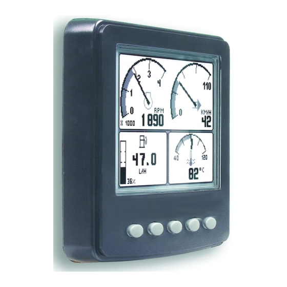
2. Understanding The Engine Monitor The Engine Monitor software runs on a KAntrak™ display (see section 19 for further details on the KAntrak™ platform) with five soft keys, providing a flexible and intuitive Human-Machine Interface (HMI). The 5 soft keys access a graphical menu structure that uses standard and easily- understood icons to indicate the key’s current function. This enables the operator to select the required engine/transmission data and display it in the following formats: • Analogue gauges • Digital values • Historical trend graphs • Current and stored alarm messages Additionally, various diagnostic screens are available, allowing detailed investigation of the engine and transmission data stream. The underlying structure of the Engine Monitor and its interaction with the soft keys may be understood by Figure 1. By accessing the Configuration menu, users can customise some of the displayed data to show, for example, metric or imperial units, and various parameters such as the full-scale reading of gauges. page 4…
-
Page 6
Understanding The Engine Monitor — continued The Engine Monitor presents a context dependent ‘button bar’ above the push buttons if any key from 1 to 4 is pressed from left to right — it disappears after 5 seconds of inactivity. This ‘top level’ button bar shows the basic structure of the Engine Monitor: Figure 1 Key 1: Key 2: Key 3: Key 4: Key 5: Tri Display, or QuadDisplay Uni Display Active Alarm Contrast Main Engine (user showing Display. Holding and Lighting Display. Repeat configurable). data history the key brings adjustment, presses Repeat presses (configurable). up Stored or — if held for 3 cycle the fuel… -
Page 7: Getting Started
3. Getting Started When power is applied to the display, a start-up screen displays for approximately 7 seconds while the display performs a self test. If the display makes a ‘bleep-ing’ sound for longer than 1 second, self-test has failed. Users can attempt to rectify the fault by restoring factory defaults (see Configuration menu/section 10 for details); if the fault persists, contact your supplier for guidance. After the start-up screen disappears, the Engine Monitor starts displaying readings on its virtual gauges if it is connected to an active source of data. The Engine Monitor displays the ‘main engine display’ or tri-screen on initial start-up, but note that after use this changes to the screen that was last displayed (see Preferred Screen Store/section 13 for details). The Engine Monitor display modes are detailed in the following sections. page 6…
-
Page 8: Soft Keys
4. Soft Keys The Engine Monitor’s soft keys simplify the operator interface. In use, the Engine Monitor displays a ‘button bar’ directly above the soft keys when any of the first 4 keys (keys 1 to 4, starting from the left) are pressed — with icons representing the current function of each key. Figure 2. shows the top level button bar, with icons 1 to 4 representing the gauges and alarms available, and icon 5 an ‘exit door’. Repeat presses of these buttons toggles around the display options available. The button bar will disappear after approximately 5 seconds if no further keys are pressed. Figure 2. The Engine Monitor’s top level button bar menu: Key 1: Pages icon indicating that further presses cycle through options for the screen being viewed (in this instance fuel computer modes for the main engine display) Key 2: Quad Display mode Key 3: Uni Display mode…
-
Page 9: The Tri Display
5. The Tri Display This Engine Monitor display mode provides three independent windows, and is intended to show the most frequently accessed vehicle data (RPM, speed, temperature and fuel). To select Tri Display, press any of the first 4 keys to show the top level button bar, and then press key 1 (the left-hand key). The parameter displayed in the top right gauge is user defined, to change the displayed data press key 5 when the button bar is visible and then keys 1 and 2 to cycle through the available parameters. Also the data displayed in the fuel computer window (Bottom left window) may be changed by repeated pressing of key 1, This is explained in more detail in the following pages. Also, attributes such as units and scales may be changed via the Configuration menu (See section 10 for details). The top window shows 2 analogue gauges; Engine RPM and Speed (maximum RPM and speed may be set via the Configuration menu). If speed data is not available the right hand gauge will display engine oil pressure. The bottom right window shows coolant temperature. The bottom left window displays the fuel computer. It is also possible to display speed derived from a GPS module with an NMEA 0183 output — interfaced via the display’s RS232 Figure 3.1. Tri Display, accessed via key 1. port (contact your Engine Monitor supplier for Note. Metric units are shown as default, but others may be further information).
-
Page 10
5. The Tri Display (Fuel Computer Modes) The lower left display window provides access to the fuel computer data and also shows fuel tank level. Upon pressing key 1 the fuel computer is highlighted, when highlighted various data can be displayed by repeat pressing of key 1. When first selected a small icon will also appear in the centre of the screen with the text “Hold Reset”. Holding key 1 at this time will perform a Trip Reset. After 2 seconds of no key presses the fuel computer will go back to normal Figure 3.2. A fuel computer and the icon will disappear. display. Note. Metric units are shown as Data Available is similar to an automotive in-car fuel computer. default, but others may be selected via the configuration menu. Below is the list of parameters that can be displayed in the fuel computer window in alphabetical order: Distance Remaining: Calculated if Fuel Tank Capacity is set and Fuel Rate, Vehicle Speed and Fuel Level are available [Distance]… -
Page 11
5. The Tri Display (Fuel Computer Modes) — continued Trip Distance: Calculated since last Trip Reset if Total Vehicle Distance is availiable [Distance] Trip Engine Hours: Calculated since last Trip Reset if Total Engine Hours is availiable [Hours] Trip Fuel: Calculated since last Trip Reset if Total Fuel Used is availiable [Volume] Trip Fuel Economy: Calculated since last Trip Reset if Total Fuel Used and Total Vehicle Distance are available [Distance/Volume] Trip Fuel Rate: Calculated since last Trip Reset if Total Engine Hours and Total Fuel Used are available [Volume/Hour] Note. A Trip Reset affects all reset-able fuel computer parameters and can be performed by holding key 1 when the Hold Reset icon appears. The icon appears for approximately 2 seconds when the fuel computer window is first selected. Setting Total Fuel Tank Data and Fuel Tank Reset is performed via the Configuration menu. page 10… -
Page 12: The Quad Display
6. The Quad Display Quad Display mode provides 4 gauges. To select it, press any of the keys 1 to 4 to show the top level button bar and then key 2. Repeat presses of key 2 cycle the display around 3 separate quad screens: 4 digital gauges, 4 analogue gauges and 4 alternative analogue gauges. All 12 gauges may be selected and configured by users, providing a simple means of creating application-specific views of engine data. Gauges are selected via quad display’s ‘adjust mode’, by pressing key 5 (noted by an arrow icon) when the Engine Monitor is running quad display and the button bar is visible. In adjust mode, corresponding key presses cycle the display through available parameters (listed in section 8). The selected configuration is stored even when power is removed; adjust mode is exited by pressing key 5. Figure 4. Top row: the 3 default displays available in quad-display, and adjust mode (right) which allows users to select the gauges displayed. Note. If a parameter is not available from the engine/ transmission, it will not be possible to select it.
-
Page 13: The Uni Display
7. The Uni Display The Engine Monitor’s Uni Display mode plots data history in one large window — in an X-Y graph format similar to a pen plotter. This mode is selected by pressing any of the first 4 keys to show the top level button bar and then key 3. Data is shown in graph form, with the most recent data scrolling from right to left. The viewed time range may be adjusted in the Configuration menu from 2 minutes to 8 hours in six steps. Maximum and minimum values of the Y axis (the reading span) are Figure 5. Example graph display plotting battery adjusted automatically to give an optimum potential switched.
-
Page 14: Data Parameters Monitored
8. Data Parameters Monitored This table lists the engine and transmission parameters that are monitored via the J1939 and/or the J1587 datalinks. The parameters can be displayed by the Engine Monitor in user-configurable Tri Display, Quad Display or Uni Display modes (√ indicates the parameter may be selected). DB is an abbreviation for the Engine Monitor’s internal database, which stores all data transmitted from the engine/transmission. The complete database list can be accessed on the display via the Configuration menu. Abbreviations: The units ‘MPG’ and ‘Gal’ denote US gallons. For non-US Imperial gallons (UK, Canada, etc) the units are denoted as ‘IMPG’ or ‘IGal’. N = nautical. KTS = knots Note. If a parameter is not available, it will not be possible to select it. If the parameter becomes unavailable while in view, ‘- — -‘ is displayed. Datalinks Screens Icon Parameter J1939 J1587 Quad ELECTRICAL (Volts or Amps) Electrical Potential √ √ √ √ √ √ Battery Potential Switched √ √ √ √ √ √ Net Battery Current √ √ √ √ √ √…
-
Page 15
8. Data Parameters Monitored — continued Datalinks Screens Icon Parameter J1939 J1587 Quad FUEL (L, Gal, lGal) or(L/h, Gal/h IGal/h) or (km/L, MPG or IMPG) Fuel Remaining √ √ √ √ Fuel Rate √ √ √ √ √ √ Instantaneous Fuel Economy √ √ √ √ Trip Fuel Economy √ √ √ √ Trip Fuel √ √ √ √ Trip Fuel Rate √ √ √ √… -
Page 16
8. Data Parameters Monitored — continued Datalinks Screens Icon Parameter J1939 J1587 Quad PRESSURE (kPa, PSI or bar) Fuel Delivery Pressure √ √ √ √ √ √ Barometer Pressure √ √ √ √ √ Auxiliary Pressure 1 √ √ √ √ Boost Pressure √ √ √ √ √ √ Air Inlet Pressure √ √ √ √ √ Air Filter 1 Differential Pressure √… -
Page 17
8. Data Parameters Monitored — continued Datalinks Screens Icon Parameter J1939 J1587 Quad TEMPERATURE (ºC or ºF) Transmission Oil Temperature √ √ √ √ √ √ Turbo Oil Temperature √ √ √ √ √ Fuel Temperature √ √ √ √ √ Intake Manifold 1 Temperature √ √ √ √ √ √ Air Inlet Temperature √… -
Page 18
8. Data Parameters Monitored — continued Datalinks Screens Icon Parameter J1939 J1587 Quad PERCENTAGE (%) Coolant Level √ √ √ √ √ Estimated Percent Fan Speed √ √ √ √ Drivers Demand Percent Torque √ √ Actual Engine Percent Torque √ √ √ √ Torque Use at RPM √ √ √ √ √ Soot Load Percent √ √ √ √ Ash Load Percent √… -
Page 19: Active And Stored Alarm Lists
9. Active and Stored Alarm Lists Active alarms. When an active/current alarm is received, a flashing pop-up window appears overlaid on the current screen in use, showing details of the current alarm. When an active alarm is received, the Engine Monitor activates its internal sounder, and the external alarm output on Pin 11 (if available on the KAntrak™ you have chosen). Figure 6. Example alarm message, plus alarm list screens showing unacknowledged conditions (black background) and acknowledged alarms (grey background). After acknowledgement, the exit key (open door icon) becomes active. J1939-standard abbreviations are used wherever possible, Note. “MS” = Most Severe, “MOD”= Moderately Severe and “LS”…
-
Page 20
9. Active and Stored Alarm Lists — continued When first entering the screen, the list automatically displays the most recent alarm. The list can be scrolled using keys 1 and 2. This screen cannot be exited until all alarms have been acknowledged by pressing key 3. Alarm messages are automatically cleared from the list when no longer received by the Engine Monitor. Stored alarms. Alarms stored by engine/transmission ECU’s (i.e. not active or current but old/ historical alarms) may be viewed by pressing and holding key 4 while the active alarm list screen is visible. On entry to this page, the Engine Monitor sends a data request to the engine/ transmission. The engine/transmission sends the stored alarm data to the Engine Monitor, which is decoded and displayed in a similar fashion to active alarms. The Engine Monitor displays an error message if there is no response from the engine/transmission. If the engine/ transmission supports the erasure of stored alarms, they may now be erased by holding key 3. Figure 7. An example Stored Alarm List screen. page 19… -
Page 21: Configuration Menu
10. Configuration Menu This mode allows users to set various Engine Monitor operating parameters such as imperial or metric units, scale limits for speedometer, engine service interval, etc. The configuration menu is entered by pressing and holding key 5 (the right hand key) for at least 3 seconds while the Engine Monitor is in normal operating mode. The top level configuration menu will be displayed as shown. Keys 1 and 2 then allow you to choose from SETTINGS, SYSTEM or Db VIEWER (The chosen item is highlighted in bold with an arrow pointing to it). Pressing key 4 enters the chosen sub-menu. SETTINGS allows the Engine Monitor to be configured according to user preferences. SYSTEM accesses maintenance and low level system configuration settings. Db VIEWER allows the user to view all data (including that that cannot be found in the graphical screens) that the Engine Monitor decodes. Each of these sub-menus is described in more detail on the pages following. Pressing key 5 exits the current menu/sub-menu. Settings are automatically stored on exit.
-
Page 22
10. Settings Sub-Menu (2nd Level Configuration Menu) The settings menu allows the user to enter sub-level screens to configure: UnITs: This menu enables the user to set the units used for speed, distance, pressure, volume and temperature. LAngUAgE: Choose from various languages. BLEEp: When activated, the soft keys will emit an audible “bleep”. Use this menu to switch the function on/off. An audible “bleep” will still sound if an alarm occurs. DIspLAy: The display menu allows the user to configure certain visual parameters and controls of the display. MAX RpM: This defines and restricts the upper limit of the RPM gauges displayed throughout the Engine Monitor. MAX spEED: This defines and restricts the upper limit of the Speed gauges displayed throughout the Engine Monitor. gRApH RAngE: This changes the resolution of the historic data displayed in the Uni Display. QUAD ADJUsT: This setting allows the user to disable the ‘adjust mode’ feature in the Quad Displays. This is generally used for users who would like to fix the parameters displayed on the screens once they are happy with them. This can be re-enabled at any time. -
Page 23
10. System Sub-Menu (2nd Level Configuration Menu) The System menu allows the user to configure or view: DEMO: Switches between the Engine Monitor’s demonstration modes and the normal mode of displaying live engine/ transmission data. Demo allows the Engine Monitor to operate without live data and provides 3 levels of simulation data: 1 = Speed On; 2 = Speed Off; 3 = Alarms On (0 = OFF). Demo is automatically set to OFF if live data is received. Setting Metric Imperial REsTORE DEFAULTs: This allows you to reset all configuration information to Language English default metric or imperial values. The default settings are: Max. RPM 4000 Max. Speed 110 KmH 70 MPH Graph range 2 mins Speed Distance Miles Pressure Volume L Temperature… -
Page 24
10. System Sub-Menu — continued cOM VIEwER: Displays last messages received on J1939 (CAN), NMEA 0183 (GPS-derived speed over ground data) and J1587 ports. System settings stored in memory can be seen in the EEPROM Viewer. Note. This is a diagnostic feature that displays the contents of the EEPROM with the current values. This may be helpful for OEMs/users diagnosing faults. DATALInk sETTIngs: This sub-menu allows the user to configure the common datalink settings (Speed Source & Trip Source) as well as the individual J1939/J1587 settings (such as source addresses). J1939 sETTIngs: This screen allows adjustments specific to the J1939 Datalink. sOURcE ADDREss 1 & 2: These settings allow the display to filter which sources it will listen to for data. Every device on a J1939 network will have a unique address (in the range 0-254) which the Engine Monitor can choose to listen to or not. The Engine Monitor can listen to 2 sources of data simultaneously (usually Engine 1 — address 0 and Transmission 1 — address 3). The filter can also be removed so that the Engine… -
Page 25
10. System Sub-Menu — continued DIspLAy ADDREss: As mentioned previously, every device has a unique address and the Engine Monitor is no different. In single engine setups the default display address is 40 (SAE recommendation). If the Engine Monitor does not display all necessary data (which is supported) please contact your engine manufacturer for advice on the value of this setting. ALARM FILTER: This setting specifies whether the Engine Monitor will monitor and display alarms from all sources (GLB, global) or only the source address’ specified in the settings Source Address 1 & 2 (SRC, source). spn VERsIOn: Set the Suspect Parameter Number [Version 1, 2 or 3]. Version 4 is automatically detected, but older engines will have to be set to 1, 2 or 3. Note. Consult your engine supplier to establish which SPN version is appropriate if you have problems reading alarm data. J1587 sETTIngs: This screen allows adjustments specific to the J1587 Datalink. sOURcE ADDREss 1 & 2: J1587 supports source addresses in the form of the MID (Message ID) and has values defined from 128 (Engine 1) to 250 (Steering Column Unit) with all other values reserved. 255 is a special case, it indicates all data from all sources in its raw data form. Source Address 1 defaults to 128 and Source Address 2 defaults to 130. DIspLAy ADDREss: The display address allows values from 128-255. -
Page 26
10. System Sub-Menu — continued spEED sOURcE: There are currently 3 sources of speed data, which the Engine Monitor can decode. The settings for this parameter are AUTO, NMEA, WHEEL, NAV and OFF. AUTO prioritises the following sources (highest to lowest) NMEA, WHEEL (PGN 0xFEF1), NAV (PGN 0xFEF8). The remaining settings force the Engine Monitor to listen only for that particular source (and OFF stops the Engine Monitor listening to any source). pIn sETTIngs: By default this security feature is disabled within the software. By enabling this feature the user will be prompted to enter a PIN every time the Configuration menu is entered. This is to allow the unit’s settings to be preserved and not be accidentally changed by an unauthorised user. To enable the PIN entry feature highlight the corresponding setting in the PIN Setting’s menu and press key 4 to select it. As an added security feature (to stop the pin being enabled without knowing it) the current pin must be entered (default is “1111”). Once this has been entered the feature will be enabled. It is possible to change the pin using the Pin Change menu. This will then prompt the user for the current pin and providing this is correct the Engine Monitor will prompt the user for the new pin and finally confirmation of the new pin. -
Page 27: Pop-Up Messages And Warnings
11. Pop-Up Messages and Warnings ENGINE SERVICE WARNING. In the Configuration menu, users can set the engine service interval in hours. When the Engine Monitor determines an engine service is due, it displays SERVICE REQUIRED on the splash screen that appears at power-up. DATA COMMUNICATIONS FAILURE. If the Engine Monitor cannot detect engine/transmission data broadcasts, a pop-up window with a data communications failure warning icon will appear and flash. Once engine/transmission data is detected the warning disappears and normal data display resumes. CAN TX DISABLE. If CAN TX (transmission) is disabled, then the status will be displayed, with a pop-up window flashing with a period of approximately 1 second on, 10 seconds off. Note. This function is a requirement of the J1939 specification and is not normally of importance for the Engine Monitor applications. DATA NOT SUPPORTED. If the required data parameter is not available, the gauge will display “ — — — “ near the units and parameter icon (see below centre for example) Figure 9. Left to right. Pop-up warnings of: engine service required, a data communications failure, and CAN TX is disabled. page 26…
-
Page 28: Tier 4 Pop-Up Messages And Warnings
12. Tier 4 pop-up messages and warnings REGENERATION: In settings menu, it is possible to activate Tier 4 pop-up. If activated, a pop-up will indicate active regeneration. REGENERATION INHIBITED: In settings menu, it is possible to activate Tier 4 pop-up. If activated, a pop-up will indicate if regeneration is inhibited by inhibit switch. Both regeneration and regeneration inhibited status can be seen in quad screen if Tier 4 pop-up is not activated. Figure 10. Left to right. Pop-up of regeneration inhibited, regeneration active, and regeneration status in quad screen. page 27…
-
Page 29: Adjusting Lighting And Contrast
13. Adjusting Lighting and Contrast Pressing key 5 (the right-hand key) when the menu icons are not being displayed brings up the lighting and contrast menu. The LCD has a number of back-lighting levels that allow the display to be read in the dark. The appropriate level is selected by pressing keys 1 or 2 to decrease or increase illumination. Contrast is adjusted in the same manner, using keys 3 and 4 (Figure 10). Note. The Engine Monitor monitors the temperature of the LCD and automatically adjusts display contrast as required, therefore it is not likely that a user will need to make a manual contrast adjustment unless extreme climate changes occur. The menu is exited by pressing key 5. The lighting and contrast settings are retained after the unit is switched off. Note. Resetting contrast. If the contrast has been adjusted poorly, you may restore the factory setting (a central value) by pressing keys 1 to 4 simultaneously. This action does not change other user-configured settings. Figure 11.
-
Page 30: Preferred Screen Store
14. Preferred Screen Store The Engine Monitor automatically stores the current screen as a user’s preferred page, after a delay of approximately 15 seconds (if no buttons are pushed). On next power-up the display will start with the splash screen, and then go to the last stored screen. Note. Selecting Restore Defaults on the Systems sub-menu of Configuration will set the main engine screen as the default display. 15. Keypad Lock The Engine Monitor’s five keys can be locked, such that an operator cannot change any settings or access any other display mode. (in a similar manner to the key lock functions on a mobile phone). This is achieved by pressing and holding keys 1 and 5 simultaneously for one second. Repeating this operation resets the Engine Monitor/KAntrak™ back to normal operation. page 29…
-
Page 31: Connector Pin-Out
16. Connector Pin-Out The Engine Monitor interfaces to data via the Deutsch DT0412PA connector on the rear of the display — wired as shown. Kongsberg Automotive can supply 2 harnesses for this purpose: A Power/CAN/Output* harness — Part No. 510623 A Power/CAN/GPS** harness — Part No. 510626 Alternatively, Kongsberg Automotive can supply the mating connector parts in kit form (Part No. 531006). Similarly you can source them from Deutsch (www.deutschecd.com): DT0612SA, mating connector W12S, wedgelock (one per connector) 0462-201-1631, pin sockets (note that different finishes and termination methods may be selected) 114017, sealing plug (one per unused pin location) (*If supported by the hardware platform) (**If supported by the software platform) Note. A ferrite clamp must be placed over the harness to meet EMC radiated emission requirements of BSEN60945 (Maritime navigation & radio communication equipment & systems). We recommend that the clamp should be a TDK ZCAT2032-0930, a Multicomp 33RH17 5X28 5X10 7: core, 10.7MM ID or equivalent. page 30…
-
Page 32
16. Connector Pin-Out — continued Connector pin-out Signal Notes Power — Ground & power (10-30V DC). Supply should be protected by 500mA-rated circuit breaker/fuse Power + TX (+) TX (-) RS-232 serial port RX (-) RX (+) CAN LO (J1939 CAN2.0B port CAN HI (J1939 HI) RS485A (J1587+) Serial port RS485B (J1587-) Output Programmable digital output for activating alarm* Not used page 31… -
Page 33: Typical J1939 Wiring Topology
17. Typical J1939 Wiring Topology Most Modern engine installations include a harness with built in J1939 backbone (Check engine manufacturer’s documentation). If not, it is critical to use twisted shielded pair with a drain wire (max length 40m) terminated with 120Ω resistors at each end. In addition, all stubs should not exceed 1m in length. KAntrak™ Display Termination Resistor (120Ω) Backbone (Max length 40m) Stub (Max length 1m) Engine and/or Transmission Termination Resistor (120Ω) page 32…
-
Page 34: Installation
18. Installation Front mounting instructions. Most units will be mounted onto a bulkhead, dashboard or panel — a method described below; the components required (4 x M4 studs and thumbnuts) are supplied with every Engine Monitor. Instructions: • Decide on a location. • Allow adequate clearance behind the display for cable connections, to ensure that the cables are not unduly stressed, and for ventilation. Leave sufficient cable so that the unit may be removed for servicing. • Using the template supplied with the display as a guide, cut out the mounting hole, and drill four ø4.3mm (0.170inch) holes for the M4 studs. • Screw the studs into the rear case; longer studs can be used (not supplied). • Connect the cable (not supplied). • Place the Engine Monitor in position, secure by screwing thumbnuts onto the studs. page 33…
-
Page 35
18. Installation — continued Front mounting template. A paper mounting template for marking drill holes etc, is supplied loose with the Engine Monitor. After marking out, Kongsberg Automotive advises that dimensions are verified by measurement, due to the limitations of the printing process. This is especially important if the template has been photocopied. Other mounting options: Rear mounting KAntrak™ 2700 and 2710 displays. Users can also mount most Engine Monitor’s displays from the rear of a panel. Users can either fabricate their own mounting arrangements or use Kongsberg Automotive’s Rear Mounting Bracket: Part Number 900061 (see datasheet at www.www.kongsbergautomotive.com for details). Take the same precautions as when front mounting. Contact Kongsberg Automotive if you require a mounting template. page 34… -
Page 36: Maintenance And Troubleshooting
19. Maintenance and Troubleshooting No regular maintenance is required, except for cleaning the Engine Monitor lens as required using a soft, damp cloth. Do not use abrasive materials or solvents, specifically white spirit, petrol and acetone. Should any further attention be necessary, please contact your supplier. If you are experiencing operating problems with the Engine Monitor, check these diagnostics: Problem Possible solution Unit does not power up Ensure connections to unit are correct. Ensure power source is present. Display is blank or black Adjust/reset lighting and contrast settings. Ensure temperature is within operating range of the unit. Unit bleeps at start-up and does Unit has failed self-test. Contact your Engine Monitor not store settings supplier Unit fails to display any data Ensure connections to unit are correct. Ensure data source supports J1939 or J1587 message protocol.
-
Page 37: The Kantrak™ Platform
20. The KAntrak™ Platform The Engine Monitor software runs on Kongsberg Automotive’ KAntrak™ LCD displays. These are rugged 110x110mm DIN-format modules with 5 soft keys, and offer a 160 x 128 pixel display area. This is large enough to provide great flexibility for managing the rich data available from modern electronically controlled systems. KAntrak™ is now in its fifth generation: the latest KAntrak™ 2700 family employs design-for-manufacture techniques including chip-on-tab to minimise component count and assembly operations. The KAntrak™ 2700 series of displays employ film supertwist nematic LCDs for visibility in direct sunlight — with backlighting. They offer a Deutsch connector interface to the network, and protection to IP67 which covers immersion in water up to 1 meter. Units come with 3 serial interfaces: RS-232, RS-485 (J1708), and a CAN 2.0B port compatible with the J1939 protocol used by many manufacturers. There are 2 variants: KAntrak™ 2700 operates over a range of -25 to +75ºC; 2710 incorporates a heating element, supporting automotive industry requirements of -40ºC. The KAntrak™ 2710 also includes a programmable 500mA digital Output Driver. Datasheets via: www.kongsbergautomotive.com page 36…
-
Page 38: Software Development
21. Software Development Options for the KAntrak™ Customers have a range of options for creating user interfaces on KAntrak™: Like a PC, a KAntrak™ needs application software to provide a useful function. The Engine Monitor application software, written by Kongsberg Automotive, is just one example. KAntrak™ may be programmed to perform an infinite number of display, control and data logging tasks. To help modify existing software or write new application software Kongsberg Automotive has developed a software development kit (SDK). This is available for programming the microcontroller used in KAntrak™ — allowing complete control of the display hardware. Purchasers of a SDK and suitable compiler are given a number of hours of free technical support from Kongsberg Automotive’s application engineering team — which may be used to write some or all of the customer-specified application software; alternatively the time may be used for training, trouble-shooting and advice. As well as supplying and supporting the SDK, Kongsberg Automotive offers a fast-turnaround and cost effective software development service for KAntrak™ using the same SDK. These projects can range from something as simple as placing a customer’s logo on the splash screen, through additional pages of data on a branded version of the Engine Monitor, to a full application with custom user interfaces, control programs, communication protocols, etc. If you would like to discuss the purchase of an SDK, or obtain a quote for custom application software, please contact us. More information is available via www.kongsbergautomotive.com page 37…
-
Page 39: Glossary
22. Glossary CAN Controller Area Network (also referred to as CANbus); serial communications protocol for automotive use KAntrak™ Intelligent CAN-compatible LCD display module FMI Failure Mode Identifier GPS Global Positioning System HMI Human-Machine Interface International Standard Organisation J1939 SAE engine data protocol using CAN 2.0B J1587 Electronic Data Interchange between Microcomputer Systems in Heavy-Duty Vehicle Applications LCD Liquid Crystal Display NMEA National Marine Electronics Association; serial communications protocol for marine use PID Parameter Identifier RS-232 Standard electrical interface for serial communications RS-485 Standard differential electrical interface for serial communications SAE Society of Automotive Engineers Inc. SID Subsystem Identifier Soft keys Push-button keys whose function changes according to use SPN Suspect Parameter Number: J1939-specific fault code ID number Note.
-
Page 40: Important Safety And Legal Information
23. Important Safety and Legal Information Under no circumstances shall Kongsberg Automotive or any of its subsidiary companies accept liability for any loss of data, income, incidental damage or consequential losses incurred as a result of the use of the product howsoever caused when used as a monitor for electronically- controlled engines/transmissions or other systems. • Reproduction, transfer, distribution or storage of part or all of the contents in this document in any form without written permission of Kongsberg Automotive is prohibited. • Kongsberg Automotive operates a policy of continuous improvement. Kongsberg Automotive reserves the right to alter and improve the KAntrak™ displays and the Engine Monitor software without prior notice. Liquid crystal safety. If the liquid crystal display (LCD) is broken, particular care must be taken with any leaking fluid. Urgent action must be taken: • If the LCD fluid gets onto your skin wipe immediately with a suitable cloth and wash the area well with mild soap and water. • If the LCD fluid gets into your eye thoroughly rinse your eye with clean water for several minutes and then gain immediate medical assistance. • If the LCD fluid is swallowed rinse your mouth thoroughly with clean water then drink a substantial volume of water and make yourself vomit. Then gain immediate medical assistance. CE EMC Directive 89/336/EE. This product has been designed to be compliant with this directive. Compliance can only be ensured by correct installation. page 39…
-
Page 41
. c o m D or s e t , ©Kongsberg Automotive 2011. Specifications subject to change without notice. B H 2 1 4 JT Any trademarks used are recognised and are the property of their respective owners.
- Manuals
- Brands
- Kongsberg Manuals
- Marine Radio
- cNODE Maxi
- Instruction manual
-
Contents
-
Table of Contents
-
Bookmarks
Quick Links
Instruction Manual
cNODE
®
Maxi and Midi Transponders
Medium Frequency, 4000 metres
Related Manuals for Kongsberg cNODE Maxi
Summary of Contents for Kongsberg cNODE Maxi
-
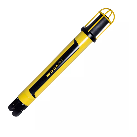
Page 1
Instruction Manual cNODE ® Maxi and Midi Transponders Medium Frequency, 4000 metres… -
Page 3
Kongsberg cNODE Maxi and Midi, Medium Frequency, 4000 m Instruction Manual 322217/G August 2019 © Kongsberg Maritime AS… -
Page 4
Kongsberg Maritime disclaims any responsibility for damage or injury caused by improper installation, use or maintenance of the equipment. Disclaimer Kongsberg Maritime AS endeavours to ensure that all information in this document is correct and fairly stated, but does not accept liability for any errors or omissions. Support information If you require maintenance or repair, contact Kongsberg Maritime’s… -
Page 5: Table Of Contents
Instruction Manual Table of contents IMPORTANT — BATTERY SAFETY ……….7 ABOUT THIS MANUAL ………….. 8 KONGSBERG CNODE …………..9 System description ………………….10 Naming description………………….10 Scope of supply…………………… 11 General supply conditions………………..12 Receipt, unpacking and storage…………….12 Equipment responsibility………………12 Support information ………………….13 SYSTEM UNITS …………..
-
Page 6
Kongsberg cNODE Installing a floating collar ………………..38 Deploying a transponder with a floating collar…………..39 Releasing the transponder manually …………….40 Closing the release unit………………..40 Adding weight to the release unit ………………41 Default transmit power ………………..42 Extending the battery lifetime………………42 EMERGENCY PROCEDURES ………… 43 Safety features……………………44… -
Page 7
Release end cap Spare part ………………..61 Sensor interface end cap Spare part ……………..62 MGC end cap Spare part………………..62 Inclinometer end cap Spare part ………………62 cNODE Maxi Battery Spare part ………………62 cNODE Midi Battery Spare part………………62 Inclinometer sensor Spare part………………63 Inclinometer sensor Interface cable Spare part…………..63 Adapter for floating collar Spare part …………….63… -
Page 8
Kongsberg cNODE SECTION 14: Transport information…………….88 SECTION 15: Regulatory information…………….89 SECTION 16: Other information ………………89 322217/G… -
Page 9: Important — Battery Safety
Important — Battery safety Important — Battery safety Read the lithium batteries safety procedure before handling batteries. WARNING The transponders are equipped with lithium batteries which can potentially be dangerous. Read the lithium batteries safety procedure before handling batteries. 322217/G…
-
Page 10: About This Manual
Microsoft Corporation in the United States and other countries. ® HiPAP is a registered trademark of Kongsberg Maritime AS in Norway and other countries. cNODE ® is a registered trademark of Kongsberg Maritime AS in Norway and other countries.
-
Page 11: Kongsberg Cnode
Kongsberg cNODE Kongsberg cNODE Topics System description, page 10 Naming description, page 10 Scope of supply, page 11 General supply conditions, page 12 Support information, page 13 322217/G…
-
Page 12: System Description
Kongsberg cNODE Instruction Manual System description cNODE is a family of transponders for underwater positioning and data links, and operates with HiPAP, HPR and cPAP transceivers. cNODE is designed to be a very versatile system with many interchangeable parts. The transponders are…
-
Page 13: Scope Of Supply
Kongsberg cNODE Transducer Beamwidth 180 = 180° beam width 30V30H = 30° vertical and 30° horizontal beam width 30V = 30° vertical beam width Optional transponder modules : Release mechanism : Inclinometer sensor : Differential inclinometer sensor : Sensor interface…
-
Page 14: General Supply Conditions
All equipment must be inspected for physical damage, i.e. broken controls and indicators, dents, scratches etc. during unpacking. If any damage to the equipment is discovered, the recipient must notify both the transportation company and Kongsberg Maritime so that Kongsberg Maritime can arrange for replacement or repair of the damaged equipment.
-
Page 15: Support Information
Kongsberg cNODE Support information Should you need technical support for your cNODE you must contact a Kongsberg Maritime office. A list of all our offices is provided on our website. You can also contact our main support office in Norway.
-
Page 16: System Units
Kongsberg cNODE Instruction Manual System units Topics Transducers, page 15 Remote transducers, page 15 Modular top section (MTS), page 17 Modular end caps (MEC), page 17 cNODE batteries, page 19 External sensors, page 19 Accessories, page 19 322217/G…
-
Page 17: Transducers
System units Transducers For more information about our transducers, see our website. https://www.kongs- berg.com/maritime TD180 The transducer has a 180° omnidirectional beam width. TD30V30H The transducer has a 30° vertical and a 30° horizontal beam width. TD30V The transducer has a 30° vertical beam width. Remote transducers The remote transducers are connected to the top of the transponder with a cable.
-
Page 18
Kongsberg cNODE Instruction Manual TDR30V The transducer has a 30° vertical beam width. TDR30H The transducer has a 30° horizontal beam width. Split for remote transducer The split is the connection between the transponder and the remote transducer. Transducer cable The cable connects the transponder and the remote transducer. -
Page 19: Modular Top Section (Mts)
System units Modular top section (MTS) Several modules are available for different versions of the top sections. Sound velocity, Pressure and Inclinometer The SvPI module provides a full suite of precision survey grade sensors for subsea positioning. It is available in aluminium for different depths and accuracies. Modem The modem lets you send data acoustically to and from sensors and other equipment.
-
Page 20
It is available as an end cap or in a combination with an external sensor. MGC end cap The Motion Gyro Compass end cap is fitted with a Kongsberg MCG gyro and is available in aluminium for various accuracies. Sensor interface, Pressure and Inclination end cap The sensor interface, pressure and inclination end cap holds an internal pressure sensor and inclination sensor units and is available in aluminium. -
Page 21: Cnode Batteries
These are non-rechargeable lithium batteries. cNODE Maxi battery The battery is made for cNODE Maxi and has a total energy content of 128 Ah. cNODE Midi battery The battery is made for cNODE Midi and has a total energy content of 64 Ah.
-
Page 22
Kongsberg cNODE Instruction Manual TTC 30 (Transponder Test and Configuration unit) The TTC can test all Kongsberg transponder high frequency channels, Cymbal and FSK. Transponder rack The rack can be used to fasten the transponder to a structure. Funnel collar The funnel holds the transponder into place in a structure. -
Page 23: Cable Layout And Interconnections
Cable layout and interconnections Cable layout and interconnections Topics External signal connector pinout, page 22 Sensor interface connector pinout, page 23 Inclinometer connector pinout, page 24 Sensor interface, Pressure and Inclination connector pinout, page 25 Motion Gyro Compass connector pinout, page 25 Modem interface connector pinout, page 27 Modem interface connector pinout, page 28 Jumper settings Modem, page 28…
-
Page 24: External Signal Connector Pinout
Kongsberg cNODE Instruction Manual External signal connector pinout This is the pin configuration for a male plug, as seen towards the plug (face view). Pin 1, 2 and 3 is for configuration. Pin 4 and 5 is for responder function.
-
Page 25: Sensor Interface Connector Pinout
Cable layout and interconnections Sensor interface connector pinout This is the pin configuration for a male plug, as seen towards the plug (face view). Pin number Signal RS-232 Tx Sensor interface 1 RS-232 Rx Sensor interface 1 Ground RS-232 Tx Sensor interface 3 RS-232 Rx Sensor interface 3 Ground RS-422 Tx +/RS-485 Data +…
-
Page 26: Inclinometer Connector Pinout
Kongsberg cNODE Instruction Manual Inclinometer connector pinout The external differential inclinometer module is connected to the inclinometer module via a cable. Both modules have the same connector and wiring specifications. This is the pin configuration for a male plug, as seen towards the plug (face view).
-
Page 27: Sensor Interface, Pressure And Inclination Connector Pinout
Cable layout and interconnections Sensor interface, Pressure and Inclination connector pinout This is the pin configuration for a male plug, as seen towards the plug (face view). Pin number Signal RS-422 Tx + RS-422 Tx – RS-422 Rx + RS-422 Rx – RS-232 Tx Sensor interface RS-232 Rx Sensor interface Ground…
-
Page 28
Kongsberg cNODE Instruction Manual Pin number Signal TD + TD – RD + RD – RS-232 Tx Sensor interface 3 RS-232 Rx Sensor interface 3 Ground COM2_OUT COM3_IN_A DC Out Ground VDC Out 24V VDC In DC In Ground Remote On/Off… -
Page 29: Modem Interface Connector Pinout
Cable layout and interconnections For deck calibration without a TTC30 an external 24V supply must be connected to IN_EXT_POWER and the ON/OFF signal must be connected to GND. Modem interface connector pinout This is the pinout for a 6–pin end cap. This is the pin configuration for a male plug, as seen towards the plug (face view).
-
Page 30: Modem Interface Connector Pinout
Kongsberg cNODE Instruction Manual Modem interface connector pinout This is the pinout for an 8–pin top section. This is the pin configuration for a male plug, as seen towards the plug (face view). Pin number Signal RS-232 Tx RS-232 Rx…
-
Page 31
Cable layout and interconnections Jumper number RS-232 RS-422 RS-485 ST10 ST11 ST12 ST13 ST14 ST15 ST16 ST17 ST18 ST19 ST20 ST21 ST22 ST23 ST24 322217/G… -
Page 32: General Acoustic Considerations
Kongsberg cNODE Instruction Manual General acoustic considerations Take this information into consideration when deploying the transponders. Acoustic range The depth rating should not be confused with acoustic range. The acoustic range is dependent on many factors, and some of the factors are outside control of the user.
-
Page 33
General acoustic considerations Sound velocity and ray bending Changes in sound velocity through the water column caused by changes in the water temperature and/or salinity can bend the acoustic signal and make it impossible to reach the vessel. 322217/G… -
Page 34: Getting Started
Kongsberg cNODE Instruction Manual Getting started Topics Turning on the cNODE, page 33 Turning off the cNODE, page 34 Pre-deployment checks, page 34 Changing between responder and transponder mode, page 35 Installing a differential inclinometer, page 36 Installing a sea current meter, page 36…
-
Page 35: Turning On The Cnode
Getting started Turning on the cNODE The transponder is designed for operation in water only. The transponder may be operated in air for test purposes over a short period of time. Context For safety reasons, the transponder is delivered with the battery outside. The battery must be inserted and connected before the transponder is deployed.
-
Page 36: Turning Off The Cnode
Kongsberg cNODE Instruction Manual Turning off the cNODE This will leave you with the transponder turned off and not using up the battery. Prerequisites WARNING Remove the battery when storing the transponder for a longer period (months). Procedure Pull out the plastic locking cord that secures the transducer in place.
-
Page 37: Changing Between Responder And Transponder Mode
Getting started Press the pressure relief valve in, to confirm it is flush with the end cap. Check the following if a floating collar is used with the transponder: Make sure the transponder is properly attached to the floating collar. Make sure the weight is properly attached to the release.
-
Page 38: Installing A Differential Inclinometer
Kongsberg cNODE Instruction Manual Installing a differential inclinometer The transponder must have an inclinometer (I) end cap to be able to connect the external inclinometer sensor. Prerequisites Turn on the transponder before installation. The transponder must have an inclinometer (I) end cap to be able to connect the external inclinometer sensor.
-
Page 39
Getting started Context Note It is very important that the sea current meter’s sensor eye faces the current for the best result possible. Procedure Mount the sea current meter sensor brackets on the sensor. Make sure the angle is correct in relation to the guiding tracks on the sensor. Note The sea current meter’s sensor eye must be facing away from the transponder and other structures. -
Page 40: Installing A Transponder With An Mgc End Cap
Kongsberg cNODE Instruction Manual ® SubConn connectors should not be exposed to extended periods of heat or direct sunlight. If a connector becomes very dry, it should be soaked in fresh water before use. Mount the arrangement to the customer’s structure.
-
Page 41: Deploying A Transponder With A Floating Collar
Getting started Fasten the two securing screws on either side of the release unit. Make sure the floating collar is fastened securely. Deploying a transponder with a floating collar Prerequisites Install the floating collar before deploying the transponder. Inspect the rope on the floating collar to make sure it is still intact. Turn on the transponder before deployment.
-
Page 42: Releasing The Transponder Manually
Kongsberg cNODE Instruction Manual Releasing the transponder manually Normally the unit will be released acoustically from APOS, this procedure is for releasing manually on deck. Context The release unit can be opened manually or acoustically. Procedure • Push in the release button on the side of the release unit.
-
Page 43: Adding Weight To The Release Unit
Getting started Adding weight to the release unit This is how the anchor weight can be attached to the transponder before operation. Steel shackle Use a stainless steel D-shackle to connect the rope, soft or web lifting sling to the release mechanism.
-
Page 44: Default Transmit Power
Kongsberg cNODE Instruction Manual Default transmit power • Cymbal: Low • Phase Shift Keying: High Extending the battery lifetime Consider how to save the transponder’s battery life before deployment. Reduce the transmit power level of the transponder, or increase the interrogation interval to extend the battery lifetime.
-
Page 45: Emergency Procedures
Emergency procedures Emergency procedures Follow these procedures for transponders with lithium batteries with unknown or failing status. Always read these procedures before handling any lithium batteries. Topics Safety features, page 44 Recovering a failing transponder, page 44 Opening a transponder with defect/possibly defect battery, page 45 Handling a heated or self-heated transponder, page 45 Handling a transponder with an open relief valve, page 46 Handling heated or warm batteries, page 46…
-
Page 46: Safety Features
Resetting the valve can in certain cases be obstructed due to production of acids and salts leaking from a damaged battery. In such cases the battery and circuits may have been damaged. Please contact Kongsberg Maritime for assistance. Vent screw The vent screw is normally not operated and is for safety purposes only.
-
Page 47: Opening A Transponder With Defect/Possibly Defect Battery
Emergency procedures For batteries with normal temperature: Take out the battery, see the emergency procedure for opening a transponder with a possible defect battery. Opening a transponder with defect/possibly defect battery, page 45 For batteries with increasing temperature: See the emergency procedure for handling a heated or self-heated transponder.
-
Page 48: Handling A Transponder With An Open Relief Valve
Kongsberg cNODE Instruction Manual Take out the battery, see the emergency procedure for opening a transponder with a possible defect battery. Opening a transponder with defect/possibly defect battery, page 45 Handling a transponder with an open relief valve Always read the emergency procedures before handling lithium batteries.
-
Page 49: Handling Transponder And Separate Transponder Batteries In Case Of An External Fire
Emergency procedures Handling transponder and separate transponder batteries in case of an external fire Always read the emergency procedures before handling lithium batteries. Procedure If possible, move the battery and/or the transponder away from the fire. Cool it down using lots of cold water. Cooling down the battery with a large amount of cold water is the only way to reduce or stop the internal chemical reactions, or to limit the fire/explosions to as few battery cells as possible.
-
Page 50: Operating Procedures
Kongsberg cNODE Instruction Manual Operating procedures The transponder is operated from the HiPAP operator station APOS. • Refer to APOS online help for descriptions. 322217/G…
-
Page 51: Maintenance
Maintenance Maintenance Topics Recovering the transponder, page 50 Battery storage, page 50 Cleaning the transponder, page 51 Opening the transponder, page 51 Inserting an O-ring, page 52 Changing the battery, page 52 Replacing the sacrificial anodes, page 54 Resetting the pressure relief valve, page 54 Lubricating SubConn ®…
-
Page 52: Recovering The Transponder
Kongsberg cNODE Instruction Manual Recovering the transponder Always read the emergency procedures before handling lithium batteries. Context Avoid slamming the transponder against solid objects as it is lifted out of the water. Procedure Send an acoustic command to the transponder to release it from the weight, for transponders with a release and a floating collar.
-
Page 53: Cleaning The Transponder
Maintenance • : 1.5 % per year Next 9 years The total capacity lost over 10 years will therefore be approximately 15%. Cleaning the transponder The transponder must be cleaned after use. Procedure Remove any growth and dirt with a stiff brush or a wooden or plastic scraper. Be careful not to damage the unit.
-
Page 54: Inserting An O-Ring
Kongsberg cNODE Instruction Manual Replace the O-rings that are damaged or used for more than a year. Make sure the mating surfaces and the O-rings are completely clean. Wipe a thin film of silicone grease over the rings and mating surfaces.
-
Page 55
Maintenance Note Read the lithium batteries safety procedure before handling batteries. Do not connect the + and – electrodes on the batteries with metal or wire.. Procedure Pull out the plastic locking cord that secures the transducer in place. Remove the transducer. Remove the spent battery. -
Page 56: Replacing The Sacrificial Anodes
The Pressure relief valve can be found on the transponder bottom end cap. Procedure Clean the unit thoroughly with lots of fresh water. Push the valve back in until it sits flush with the surrounding surface. Contact Kongsberg Maritime for assistance if the valve will not reset properly. Lubricating SubConn connectors ®…
-
Page 57: Closing The Release Unit
Maintenance Fully mate the male and female connector in order to secure optimal distribution of grease on pins and in sockets. Open and check for grease on every male pin, to confirm that enough grease is applied. Add more if necessary. Connect and tighten the locking sleeve.
-
Page 58
Kongsberg cNODE Instruction Manual Procedure • Push in the release button on the side of the release unit. A sudden muted click and thud can be heard and felt. Result The release unit is now fully opened 322217/G… -
Page 59: Spare Parts
Sensor interface end cap Spare part, page 62 MGC end cap Spare part, page 62 Inclinometer end cap Spare part, page 62 cNODE Maxi Battery Spare part, page 62 cNODE Midi Battery Spare part, page 62 Inclinometer sensor Spare part, page 63…
-
Page 60
Kongsberg cNODE Instruction Manual TTC 30 (Transponder Test and Configuration unit) Spare part, page 64 Current meter Aquadopp Spare part, page 64 Aquadopp mounting clamp Spare part, page 64 Transponder rack Spare part, page 65 Funnel collar Spare part, page 65… -
Page 61: Maintenance Kit
Spare parts Maintenance kit • cNODE Maxi and Midi maintenance kit, Aluminium Part name: • 345595 Part number: This kit contains: • 1 EMI shield • 1 O-ring, 12 x 2 mm • 3 Zink anodes 207–5000 • 3 locking cords •…
-
Page 62: Td30V Spare Part
Kongsberg cNODE Instruction Manual TD30V Spare part • TD180 Aluminium Part name: • 320662 Part number: • TD180 Steel Part name: • 320077 Part number: Split for remote transducer Spare part • Split for remote transducer Aluminium Part name: •…
-
Page 63: Tdr40V Spare Part
Spare parts TDR40V Spare part • TDR40V Aluminium Part name: • 349743 Part number: • TDR40V Steel Part name: • 375360 Part number: Transducer cable Spare part • Transducer cable 6 m Part name: • 345772 Part number: Sound velocity, Pressure and Inclinometer Spare part •…
-
Page 64: Sensor Interface End Cap Spare Part
435220 Part number: Inclinometer end cap Spare part • Inclinometer end cap Steel Part name: • 320818 Part number: cNODE Maxi Battery Spare part • cNODE Maxi Battery Part name: • 319554 Part number: cNODE Midi Battery Spare part •…
-
Page 65: Inclinometer Sensor Spare Part
Spare parts Inclinometer sensor Spare part • Inclinometer sensor Spare part • 441115 Inclinometer sensor Interface cable Spare part • Inclinometer sensor Interface cable Part name: 322407 Part number: Adapter for floating collar Spare part Adapter for transponder models without a release mechanism. For use on a basic end cap with a floating collar.
-
Page 66: Transport Plug Spare Part
Kongsberg cNODE Instruction Manual Transport plug Spare part • Transport plug Part name: • 346211 Part number: TTC 30 (Transponder Test and Configuration unit) Spare part • TTC 30 (Transponder Test and Configuration unit) Part name: • 345775 Part number: Current meter Aquadopp Spare part •…
-
Page 67: Transponder Rack Spare Part
Spare parts Transponder rack Spare part • Transponder rack Part name: • 320808 Part number: Funnel collar Spare part • Funnel collar Upper part Part name: • 383679 Part number: • Funnel collar Lower part Part name: • 383683 Part number: 322217/G…
-
Page 68: About Drawings
Use the dimensions of the different components in the transponder in the technical specification to find the total dimension of your cNODE transponder. Weight and outline dimensions, page 73 Contact Kongsberg Maritime if you need an outline drawing of your specific transponder. 322217/G…
-
Page 69: Differential Inclinometer Arrangement Drawing
About drawings Differential inclinometer arrangement drawing 322217/G…
-
Page 70: Current Meter Arrangement Drawing
Kongsberg cNODE Instruction Manual Current meter arrangement drawing 322217/G…
-
Page 71: Technical Specifications
Technical specifications Technical specifications Topics Performance specifications, page 70 Weight and outline dimensions, page 73 Power requirements, page 77 Environmental requirements, page 80 322217/G…
-
Page 72: Performance Specifications
Kongsberg cNODE Instruction Manual Performance specifications These performance specifications summarize the main functional and operational characteristics of the cNODE transponder. • : 4000 m Depth range • : Medium frequency 21 – 31 kHz Operational frequency TD180 • : 180 degrees Transducer beam •…
-
Page 73
Technical specifications TDR40V • : 40° Vertical Transducer beam • : 203 dB Maximum source level • : 90 dB Receiver sensitivity Source level Maximum High Minimum 34–180 series 190 dB 184 dB 178 dB 173 dB 34–30V30H 206 dB 200 dB 194 dB 186 dB… -
Page 74
Kongsberg cNODE Instruction Manual MEC Inclinometer sensor • : ±60 degrees Maximum detectable angles : 0.25 degrees Accuracy : 0.1 degrees Resolution • : 8–pin female Subconn MCBH8F Connector • : 7–pin Gisma plug 10.00.2.07.1.10 Connector • : Maximum 9 m… -
Page 75: Weight And Outline Dimensions
Technical specifications Weight and outline dimensions These weights and outline dimension characteristics summarize the physical properties of the cNODE system. TD180 • Outline dimensions – : 169.5 mm Height – : 166 mm Diameter • : 4.1 kg Weight (In air) Aluminium •…
-
Page 76
Kongsberg cNODE Instruction Manual TDR30H • Outline dimensions – : 262.4 mm Height – : 77 mm Diameter TDR40V • Outline dimensions – : 218.6 mm Height – : 100 mm Diameter TDR30V • Outline dimensions – : 279.5 mm Height –… -
Page 77
Technical specifications Sound velocity, Pressure and Inclinometer • Outline dimensions – : 184 mm Height – : 144 mm Diameter • : 2.4 kg Weight (In air) Aluminium Basic end cap • Outline dimensions – : 40 mm Height – : 144 mm Diameter •… -
Page 78
Weight (In air) External inclinometer • Outline dimensions – : 175 mm Height – : 124 mm Diameter cNODE Maxi Floating collar 2000 m , Aluminium transponder • Outline dimensions – : 949 mm Height – : 358 mm Width –… -
Page 79: Power Requirements
Battery lifetime The lifetime ranges should be treated as approximations only. Calculations made should allow for standard deviation in battery manufacture. • :913 days Quiescent battery lifetime cNODE Maxi 34–180 series — Cymbal Update 1 second 10 s rate TX power…
-
Page 80
Kongsberg cNODE Instruction Manual cNODE Maxi 34-30V30H and other series — Cymbal Update 1 second 10 s rate TX power level Minimum 95 days 101 days 102 days 103 days 104 days 105 days 59 days 76 days 91 days… -
Page 81
Technical specifications cNODE Midi 34–180 series — Cymbal Update 1 second 10 s rate TX power level Minimum 47.5 days 50.5 days 51 days 51.5 days 52 days 52.5 days 35.5 days 42.5 days 45.5 days 47.5 days 48.5 days 50.5 days High 18 days… -
Page 82: Environmental Requirements
Kongsberg cNODE Instruction Manual cNODE Midi 34-30V30H and other series — FSK Update 1 second 10 s rate TX power level Minimum 83.5 days 86 days 87 days 87.5 days 87.5 days 88 days 62.5 days 73.5 days 78 days 80.5 days…
-
Page 83: Battery Safety
Battery safety Battery safety Topics SECTION 1: Identification, page 82 SECTION 2: Hazards identification, page 82 SECTION 3: Composition, page 83 SECTION 4: First aid measures, page 84 SECTION 5: Firefighting measures, page 84 SECTION 6: Accidental release measures, page 85 SECTION 7: Handling and storage, page 85 SECTION 8: Exposure control and personal protection, page 86 SECTION 9: Physical and chemical properties, page 86…
-
Page 84: Section 1: Identification
Kongsberg cNODE Instruction Manual SECTION 1: Identification The specification describes the technical parameters for the battery. The cNODE contains a custom made Li-Ion battery. • : L14.4 (48) Maxi Battery name • : 319554 Part number • : L14.4 (48) Maxi Exd Battery name •…
-
Page 85: Section 3: Composition
Negative electrode • : Carbon Positive electrode • : A solution of lithium tetrachloroaluminate (LiAlCl ) in thionyl chloride Electrolyte Battery identification: cNODE Maxi • : L14.4 (48) Maxi Battery name • : 319554 Part number • : 6.5 kg Battery weight •…
-
Page 86: Section 4: First Aid Measures
Kongsberg cNODE Instruction Manual In case of hazardous events, the noxious gases are: • Thionyl chloride (SOCl • Sulphur dioxide (SO • Hydrogen sulphide (H • Hydrogen chloride (HCl) • Chlorine (Cl For additional information about the cells inside the sealed battery pack, see the safety data sheet provided by the cell manufacturer.
-
Page 87: Section 6: Accidental Release Measures
Battery safety Cool it down using lots of cold water. Immerse the battery and/or the transponder in the sea for minimum 24 hours. If this method is impossible, it can be cooled down with a fire hose. Cooling down the battery with a large amount of cold water is the only way to reduce or stop the internal chemical reactions, or to limit the fire/explosions to as few battery cells as possible.
-
Page 88: Section 8: Exposure Control And Personal Protection
Kongsberg cNODE Instruction Manual Store in a dry location. Recommended relative air humidity is 40 to 70 %. To minimize any adverse affects on the battery performance it is recommended that it is kept at room temperature (25 °C +/- 5 °C). Elevated temperatures can result in shortened life.
-
Page 89: Section 10: Stability And Reactivity
Battery safety Cell manufacturer • : Saft Manufacturer • https://www.saftbatteries.com/ Manufacturer’s website SECTION 10: Stability and reactivity The battery is stable. No specific handling requirements apply. In normal use, the battery pack is placed inside the sealed transponder. Water ingress into the transponder can cause dangerous situations. Short-circuiting, overheating, mechanical damage and exposure to water can start chemical reactions and cause high currents inside the lithium battery.
-
Page 90: Section 12: Ecological Information
Kongsberg cNODE Instruction Manual SECTION 12: Ecological information The battery is not biodegradable. Provided that the battery pack is disposed of according to local regulations and/or law, it will not have any environmental impact. SECTION 13: Disposal considerations Dispose of the batteries in accordance with local, state and federal laws and regulations for batteries.
-
Page 91
Battery safety – UN no. 3090, Class 9 Miscellaneous (Lithium batteries) • Lithium batteries contained in equipment – UN no. 3091, Class 9 Miscellaneous (Lithium batteries) Note During transport a lithium battery must always be disconnected from the electronics. SECTION 15: Regulatory information Not applicable. -
Page 92
Kongsberg cNODE Instruction Manual Index 313455 361410 TD30V30H ……….59 sensor interface……….. 62 319301 369045 floating collar……….63 adapter…………. 63 319554 370447 battery …………. 62 TDR30V ……….60 319750 372953 TD180 …………. 59 adapter…………. 63 320077 375359 TD30V ………… 60 TDR30H ………. -
Page 93
Index battery storage……….50 close the release ……..40, 55 basic items deployment ……….39 provided with the delivery……11 manual release……..40, 55 battery modular top section……..17 319554 ………… 62 MTS …………17 347563 ………… 62 naming ………… 10 emergency procedures …….. -
Page 94
Kongsberg cNODE Instruction Manual modem ………… 28 lower funnel collar handling 383683 ………… 65 battery safety ……….85 lubricating hazards identification underwater connector ……..54 battery battery safety ……..82 help support offices ……….13 how to main items add weight to the release…….. 41 provided with the delivery…… -
Page 95
Index pressure sensor ……….. 61 adding weight to the release ……41 rack …………65 changing the battery ……..52 release …………. 61 changing to responder mode ……35 sensor interface……….. 62 closing the release ……..40, 55 sound velocity sensor……..61 extending the battery lifetime …… -
Page 96
Kongsberg cNODE Instruction Manual sensor interface 347652 ………… 62 target audience 361410 ………… 62 this manual……….8 spare part……….62 TD180 size 319750 ………… 59 technical specifications……..73 320877 ………… 59 sound velocity sensor spare part……….59 spare part……….61… -
Page 97
Index turn off …………34 on …………33 underwater connector lubricating……….54 unpacking general supply conditions……. 12 upper funnel collar 383679 ………… 65 vessel system about …………30 website download documents ……..8 weight technical specifications……..73 322217/G… -
Page 98
©2019 Kongsberg Maritime…
ГлавнаяБиблиотека # Library Справочники # Handbooks Устройство и эксплуатация специализированных судов # Different types os shipDynamic Positioning VesselsDynamic Positioning System ManualsKongsberg Operator ManualСистема D.P. Kongsberg (Руководство)
Вперёд >
Скачать
Последние публикации
-
20 великих стихотворений
-
Encyclopedia of Ship Technology
-
Кодекс безопасной практики размещения и крепления груза (Кодекс РКГ/CSS Code)
-
Техническое обслуживание судового навигационного электро оборудования и приборов
-
Терминологический справочник судоводителя по ведению дел и документации на английском языке
-
Технологии обработки мусора на судах. Инсинераторы
-
Theory and Practices of Marine Pilotage

Городской автобус ЛиАЗ-5292 Low floor. Фото ГАЗ
ЛиАЗ-5292 — российский городской низкопольный автобус большого класса производства Ликинского автобусного завода. Первый полностью низкопольный автобус российского производства. Предназначен для крупных городов с интенсивным пассажиропотоком. Серийно выпускается с 2004 года.
Содержание
- Подробное описание салона и не только, что такое, схемы
- Кабина
- Популярные модификации и фото
- ЛиАЗ-5292: устройство и основные технические характеристики
- Салон
- Двигатель
- Руководство по эксплуатации
- Дизельный низкопольный ЛиАЗ-529260/5292.60
- ЛиАЗ-5292.21/529221
- ЛиАЗ-5292.22/529222
- Газовый ЛИАЗ-5292.71/529271/52927 EEV
- ЛиАЗ-5292.67/529267
- ЛиАЗ-5292: устройство и основные технические характеристики
- Другие модификации: ЛиАЗ-529265, 529267
- Годы выпуска
- Основные сведения, характеристики
- Базовые характеристики: вместимость, габариты и не только
- Технические характеристики
- Характеристики шасси: задний мост и не только
- Дополнительные характеристики
- Характеристики двигателя/силового агрегата
- Дополнительные опции
- Особенности/преимущества
- Видео, обзор салона, органов управления, панели приборов и не только
- Где купить, арендовать, переоборудовать
Подробное описание салона и не только, что такое, схемы
Производитель и поставщики предлагают автобусы ЛиАЗ-5292 двух типов, с дополнением к названию 1) «Низкопольные/Low Floor» и 2) «Рестайлинг». У техники двух видов имеются как одинаковые, так и отличные друг к другу характеристики. Оба вида представляют собой автобусы большого класса, предназначен для работы на маршрутах с интенсивным пассажиропотоком.
1) Оснащен системой кузова «книлинг» (наклон кузова в сторону дверей на 7°), большой накопительной площадкой, оборудованной специальными креплениями для инвалидных колясок, аппарелью для въезда/съезда, что позволяет чувствовать себя комфортно всем категориям пассажиров. Капсуляция моторного отсека и защита двигателя позволяют уменьшить количество шума внутри и снаружи салона.

Городской автобус ЛиАЗ-5292 Рестайлинг. Фото ГАЗ
2) Новые стекловолоконные маски придают модели современный вид. Материал не подвергается коррозии, отличается легкостью и низкой стоимостью. Маска состоит из отдельных составных элементов, что повышает ремонтопригодность и позволяет сэкономить при необходимости замены деталей экстерьера.
Отсутствие ступеней обеспечивает высокую скорость пассажирообмена, что сокращает время прохождения маршрута на 15%.
Оснащены системой наклона кузова «книлинг», большой накопительной площадкой, оборудованной специальными креплениями для инвалидных колясок, аппарелью для въезда/съезда, что позволяет чувствовать себя комфортно всем категориям пассажиров.
Подробное описание автобусов предоставляют электросхемы.
Кабина
Устройство кабины автобусов (общую информацию про все кабины автобусов см. по ссылке) ЛиАЗ-5292 отличается в зависимости от модификации. Базовая модель имела кабину закрытого типа с дверью для водителя и специальным окошком. Значительная площадь остекления обеспечивала водителя отличный обзор салона. О особенностях водительской кабины некоторых других модификациях информация представлена далее.
Популярные модификации и фото
ЛиАЗ-5292: устройство и основные технические характеристики
ЛиАЗ-5292 – автобус большого класса для эксплуатации в крупных городах с большим пассажиропотоком. Эта низкопольная техника, имеющая множество модификаций, удобна и безопасна для всех групп пассажиров. Автобус выпускается «Ликинским автобусным заводом», расположенным в Орехово-Зуевском районе Московской области.
Первый экземпляр ЛиАЗ-5292.00 или ЛиАЗ-5292 был построен и продемонстрирован широкой публике на Московском автосалоне в 2003 году. Модель была запущена в серийное производство и стала поступать в мелком количестве в автобусные парки Москвы, Курска, Воронежа, Иваново и других городов. В тот момент он был «сырой» и нуждался в доработке, поскольку в наследство модели достались дизель и запчасти Caterpillar 3116, идентичный предшественнику ЛиАЗ-5256.25, размещенный поперечно салону, КПП-автомат компании Voith серии Diwa D 854.3E, а также рулевой аппарат марки Csepel A-500.73-3520-00.
В процессе проектирования машины были упущены некоторые конструктивные особенности работы, что в результате ухудшило эксплуатационные характеристики. Среди них – потребность в размещении системы АСКП, что в связи с несовпадением компоновки с панелью водительской кабины загромождало свободное пространство, уменьшало при этом максимальную вместительность, снижало производительность, экономичность и рациональность эксплуатации автобуса. Главные габариты несущего кузова вагонного типа (длина – 11,48, ширина – 2,47 и высота – 3,00 м.) не изменялись со времени первоначальной высокопольной марки ЛиАЗ-5256. В результате модель ЛиАЗ-5292 первое время была переходным экономичным вариантом в модельном ряду низкопольной техники ЛиАЗ. В результате автобусы были малопригодными к эксплуатации и производились с 2004 по 2006 год.
Салон
Автобус относился к городскому виду транспорта, широко эксплуатируемому в мегаполисах с активным потоком пассажиров. Общая вместимость пассажиров составляла 112 человек. Из них мест для сидения лишь 20, в том числе 2 сиденья для инвалидов. Дизайнерский облик в полной мере соответствовал требованиям современного автомобильного дизайна. Низко расположенный пол (автобус приподнят над поверхностью проезжей части на 34 см.) и просторный проход в дверях способствовали комфортной посадке и размещению пассажиров, что существенно уменьшало продолжительность движения по маршруту.
Двигатель
Двигатель был 6-рядным с турбонаддувом и предварительным охлаждением турбонаддувочного воздуха, обладал мощностью в 230 л.с. и соответствовал нормам Eвро-3, расход топлива составлял 29 л/100 км.
Руководство по эксплуатации
Руководство по эксплуатации отдельных модификаций ЛиАЗ-5292 возможно найти и скачать в открытом доступе. Руководства современных моделей, сходящих с конвейера в настоящее время, поставляются в комплекте с машиной.
Дизельный низкопольный ЛиАЗ-529260/5292.60
ЛиАЗ-529260 — низкопольный автобус среднего класса, предназначенный для работы на пригородных маршрутах со средним и интенсивным пассажиропотоком. Впервые эта модель была продемонстрирована в сентябре 2014-го на международном форуме в Нижнем Новгороде, в том же году было запущено ее серийное производство.
Габаритная длина составляет 10500 мм, ширина — 2500 мм (без учета наружных зеркал), высота — 2880 мм (с кондиционером – 2938 мм), межосевое расстояние — 4390 мм. Автобус весит 9280 кг, полная масса — 16200 кг (нагрузка на фронтальную ось не превышает 5580, на заднюю – 10620 кг).
Рабочее место водителя имеет сплошную перегородку (с форточкой и входной дверью), отделяющую его от пассажирского отсека.
Салон оснащен 26 сиденьями, общая вместимость равняется 75 пассажирам.
На модель устанавливается рядный шестицилиндровый дизель ЯМЗ-536111 объемом 6.65 литра (Евро-4) с турбокомпрессором, прямой системой впрыска, 12-ю клапанами, жидкостным охлаждением и интеркулером, 275 л.с. при 2300 об/минуту и 1250 Нм крутящего момента при 1300-1600 об/минуту. Двигатель работает совместно с 6-ступенчатым «автоматом» ZF 6AP-1400B и ведущими задними колесами.
Максимальная скорость 90 км/ч, потребление горючего составляет порядка 35 л. Обладает несущим цельнометаллическим кузовом вагонной компоновки. На обоих мостах установлены зависимые пневматические подвески с телескопическими амортизаторами: спереди – на двух упругих элементах с парой электронноуправляемых регуляторов положения кузова, сзади – на четырех упругих элементах с двумя механическими регуляторами положения кузова. Оснащен рулевой системой типа «винт — шариковая гайка — рейка — сектор» с гидравлическим усилителем управления, электронноуправляемым тормозным комплексом с дисковыми устройствами на всех колесах и ABS, топливным баком объемом 248 л.
5292.60-60. Укороченная до 10,5 метров версия ЛиАЗ-5292.60. Существует как в городском (три двери, 22 сидячих места), так и в пригородном (две двери, 26 сидячих мест) вариантах. Данные модификации были разработаны по заказу ГУП МО Мострансавто и их поставка в количестве 122 единиц была летом 2014 года. Особенности проектирования укороченного варианта ЛиАЗ-5292 послужила базовой основой для создания в будущем совершенно нового автобуса средней вместимости — ЛиАЗ-4292.
ЛиАЗ-5292.21/529221
Дальнейшее развитие ЛиАЗ-5292.20. Основным отличием от предшественника является двигатель MAN D0836 LOH56, отвечающий экологическим нормам Евро-4. Другими отличиями являются другая приборная панель, аналогичная московским ЛиАЗ-6213.20 2010 года выпуска и новый потолок салона, разработанный фирмой КОРА, а также схема окраски экстерьера, аналогичная ЛиАЗ-6213.20 поставки конца 2010 года. Машины, закупаемые ГУП «Мосгортранс», также оснащены точечной головной оптикой фирмы Hella и системой кондиционирования воздуха (на первых экземплярах марки Spheros, затем — Konvekta) в пассажирском салоне и кабине водителя (в автобусах, поставляемых в регионы России, кондиционер и принудительная вентиляция отсутствует).
ЛиАЗ-5292.22/529222
Модификация с двигателем MAN D0836 LOH65, отвечающим нормам Евро-5. Первый экземпляр данного типа был показан на выставке «Комтранс-2011» в сентябре 2011 года и затем отправлен на доработку. Уже в раскраске САС первый ЛиАЗ-5292.22 был отправлен в 14-й автобусный парк. Отличается новой панелью приборов, новым интерьером кабины водителя, обновлённой водительской перегородкой, и пластиковыми подиумами и кожухами колесных арок разработки фирмы КОРА.
Модификация была запущена в серийное производство в ноябре 2011 года. Первые серийные автобусы имели стандартную заводскую эмблему и салон, идентичный технике модификации ЛиАЗ-5292.21. Более поздние модели имеют обновлённую заводскую эмблему и модернизированный салон с пластиковыми подиумами разработки фирмы КОРА. Автобусы, выпускаемые с лета 2012 года, имеют салон с поручнями жёлтого цвета, цельное лобовое стекло, обрамление лобового маршрутоуказателя чёрного цвета, светодиодное освещение салона и изменённую корму — стало больше прорезей для вентиляции двигателя, также поменялся кондиционер марки Konvekta — он стал мощнее. На нескольких первых новых «чернолобых» автобусах установлены кондиционеры Konvekta старого образца. Более новые ЛиАЗ-5292.22 комплектуются сиденьями Pilot и стеклянными заглушками в нижней половине поручней.
В конце 2013 года был начат выпуск обновлённой версии автобуса 5292.22 с передней и задней масками, аналогичными ЛиАЗ-5292.30 и цельностеклянными дверями.
Начиная с конца 2017 года на заводе ЛиАЗ в следствии массового полного выхода из строя двигателей на данной модификации, на заводе ЛиАЗ автобусы модификации ЛиАЗ-5292.22 проходят замену двигателя с MAN D0836 LOH65, на ЯМЗ-53633, идентичному технике модификации 5292.65.
Газовый ЛИАЗ-5292.71/529271/52927 EEV
Модификация с газовым двигателем MAN E0836 LOH01 (6R, вертикальное, рабочий объем — 6,871 л., мощность, кВт (л.с.) — 206 (280) при 2200, максимальный крутящий момент, Нм — 1000 при 900…1900), отвечающим нормам EEV (Евро-5+) и автоматической трансмиссией нового поколения ZF EcoLife 6 AP 1200B. Первый экземпляр данной модификации был впервые показан на выставке Busworld-2010 в июле 2010 года. На нём были продемонстрированы новый салон и новый дизайн передней маски кузова.
В 2012 году запущен в серийное производство. Был установлен кондиционер Konvekta нового образца, а газовые баллоны смещены вперёд. С апреля 2012 года автобусы этой модификации оснащаются кондиционерами. В 2014 году после замены производителем автобусов баллонов типа КПГ/CNG-2 на баллоны КПГ/CNG-3 и устранения конструктивных недостатков, выявленных в ходе эксплуатации, эксплуатация данной модели в Москве было поэтапно полностью восстановлена.
Основные технические характеристики:
- Низкопольный, несущий, цельнометаллический кузов вагонной компоновки
- Передний мост ZFRL-85A — портальный, с дисковыми тормозами
- Задний мост ZF, AV-132/87/6,5 — портальный с центральным коническим редуктором, с дисковыми тормозами
- Колёсная формула — 4х2
- Длина / Ширина / Высота, мм. 11990/2500/3139
- База, мм. 5960.
- Количество дверей — 3
- Минимальный радиус разворота, м. 11
- Масса полная и снаряженная, кг. 18000 и 10350
- Нагрузка на переднюю / заднюю ось, кг. 6500/ 11500
- Общее количество мест (в т.ч. посадочных). 114 (28+1 инв), 112 (26+1 инв).
- Емкость газовых баллонов, л. 918 (9х102)
- Рулевой механизм. ZF, Servocom 8098, с гидроусилителем руля
- Тормозная система. Пневматическая, двухконтурная, ABS, ASR
- Вентиляция естественная и принудительная
- Система отопления. Жидкостная, с использованием тепла системы охлаждения двигателя и независимого жидкостного подогревателя
- Шины, колеса. 275/70 R22,5
ЛиАЗ-5292.67/529267
Модификация с газовой версией дизельного двигателя ЯМЗ-53624-40. Устанавливается коробка передач Voith Diwa 864 или ZF 6AP-1200B. В автобусах с коробкой передач Voith, устанавливаются портальные мосты китайского производства, а именно — ведущие портальные мосты типа Hande Axle HDZ13P и передние мосты Hande Axle HDZ75P. Первоначально планировалось автобусу присвоить индекс ЛиАЗ-5292.90, но в последние месяцы индекс был перенумерован. За время испытаний были выявлены недостатки, главные из которых относятся к новому на тот момент двигателю ЯМЗ: повышенный уровень шума при разгоне и возможность замены свечей только при снятии клапанной крышки.
Другие модификации: ЛиАЗ-529265, 529267
5292.20 (52922). ЛиАЗ-5292.20 был впервые продемонстрирован на Московском мотор-шоу 2007 года. Модификация была создана с помощью немецкой компании IVM Automotive с учётом требований ГУП «Мосгортранс». Автобусы этой модификации комплектуются двигателями MAN D0836 LOH41 (Евро-3), расположенным продольно, ведущими портальными («низкопольными») мостами ZF типа AV-132/87, передними портальными мостами ZF RL-85A и АКПП ZF 6 HP 504C типа Ecomat.
С 2008 года салоны ЛиАЗов для Москвы собирались на заводе Тушино-Авто. С середины 2011 года ЛиАЗ-5292.20 выпускается только для регионов России.
5292.22-01. Модификация с учебной кабиной и вентиляционными люками, аналогичными применяемым на пассажирском транспорте МАЗ. Остальное совпадает с ЛиАЗ-5292.22.

Автобус ЛиАЗ-52922 с двигателем MAN. Фото Википедия
5292.22-02. Пригородная версия ЛиАЗ-5292.22. Данная модификация не имеет задней двери, а количество посадочных мест доведено до 32 штук.
5292.22-77. Усовершенствованная версия модели ЛиАЗ-5292.22 с увеличением прохода в хвостовой части и добавлением дополнительного третьего сидения перед шахтой двигателя, увеличенная шахта двигателя и новая оптика передка и задка автобуса. Партия из данных автобусов массово закупается ГУП «Мосгортранс» начиная с осени 2015 года. Начиная с января-февраля 2016 года поступают автобусы с новыми сиденьями и кондиционерами марки Spheros, модификация которой была установлена на первые образцы ЛиАЗ-5292.21, а также кондиционерами марки Konvekta, установленные на последние модели ЛиАЗ-5292.22.
5292.30. Модификация с двигателем Scania DC09 91A, отвечающим нормам Евро-4. Первый экземпляр с полностью обновлённым дизайном был показан на выставке «Мир автобусов 2013». На выставке Комтранс-2013 был показан серийный вариант данной модификации.
5292.56. Модификация с двигателями Cummins, отвечающие нормам Euro-6 (первые дизельные двигатели, отвечающее столь высоким стандартам). Комплектуются кондиционерами Konvekta, которые намного мощнее своих предшественников.
5292.65. Модификация с двигателем ЯМЗ-53633, отвечающий нормам Euro-5. Устанавливается коробка передач Voith Diwa 864 или ZF 6AP-1400B. Автобус данной модификации выпускается в нескольких вариантах — двухдверный полунизкопольник, имеющий 33 сидячих места, задний мост высокопольный Raba—718, идентичный моделям ЛиАЗ-5256 и ЛиАЗ-5293, предназначенный для пригородных перевозок, а также стандартный полностью низкопольный автобус, идентичный остальным образцам семейства ЛиАЗ-5292 с задней шахтой и стандартные немного укороченные автобусы.
В полностью низкопольных автобусах с коробкой передач ZF устанавливаются стандартные портальные мосты типа ZF, а в автобусах с коробкой передач Voith устанавливаются портальные мосты китайского производства, а именно — ведущие портальные мосты типа Hande Axle HDZ13P и передние мосты Hande Axle HDZ75P. Первый опытный автобус данной модификации в полунизкопольном исполнении выпущен в сентябре 2015 года, серийное производство стартовало в апреле 2016 года (только производство полностью низкопольных автобусов).
В 2018 году выпущена обновлённая версия модификации ЛиАЗ-5292.65 для расширения автобусной сети, работающих по программе «Новой модели транспортного обслуживания Москвы». Светотехника и внешний вид идентичны автобусам 2016 года выпуска, исключение составляют лишь электронные маршрутоуказатели, получившие светло-зелёный, оранжевый и красный цвета. Изменения коснулись и салона — в дополнение к обычным табло установлены мониторы, три сидения перед шахтой двигателя и новая перегородка кабины водителя, унаследованная от модели ЛиАЗ-5292.22 и более поздних её модификаций. Сидения идентичны установленным в модификациях ЛиАЗ-5292.65-77.
5292.65-77. Усовершенствованная версия модификации ЛиАЗ-5292 с увеличенным задком автобуса, огромной шахтой и добавлением третьего места у шахты двигателя. Модификация по внешнему виду схожа с ЛиАЗ-5292.22-77. От ЛиАЗ-5292.22-77 отличается двигателем марки ЯМЗ-53633, устанавливаемого взамен двигателя MAN, установкой кондиционера отечественного производства марки Август.
5292.65-79. Отличительной особенностью стала установка двух мониторов в салоне, наличие трех USB-зарядок для смартфонов, установка новой приборной панели с электрорегулировкой рулевого колеса, нового бортового компьютера, наличие системы кругового видеообзора, отсутствие вентиляционных люков в потолке, установка дополнительного светового указателя. Маршрутный указатель приподнят вверх, внизу во время остановок высвечивается надпись: STOP и пассажир на лестнице, которая раньше гасла при отъезде от остановок (после перепрограммирования заменена на надпись «СПАСИБО»). Вследствие установки дополнительного указателя в области заднего стекла, установлен пластмассовый заменитель окна. Кроме этого, добавлены кнопки открытия дверей пассажирами так и снаружи, так и внутри автобуса. Кнопки включаются в работу по усмотрению водителя. В целях повышения удобства пассажиров было решено отказаться от установки трех сидений перед шахтой двигателя. Модификация 2018 года выпуска также претерпела ряд некоторых изменений — помимо вышеупомянутых изменений, теперь кондиционеры окрашиваются вместе с кузовом в голубой цвет.
5292.65-80. Оборудованы учебной кабиной, дизайн перегородки которой аналогичен обычной, но имеет несколько «сплющенный» облик вследствие расположения относительно оси кузова. Помимо этого, учебная кабина стала немного больше, чем на предыдущих учебный автобусах ЛиАЗ-5292.22-01. Вследствие установки кабины инструктора, пришлось изменить в салоне расположение некоторых сидений. Всё остальное совпадает с модификацией ЛиАЗ-5292.65-79. Автобусы данной модификации стартовали в серийное производство в конце 2017 года.
5292.67-79. Рестайлинговая версия модификации ЛиАЗ-5292.67 для Москвы с увеличенной шахтой двигателя в новом кузове. Серийный выпуск планировалось начать в 2018—2019 годах, но из-за низкой надёжности двигателя ЯМЗ53624-10 и его высокой трудоёмкости технического обслуживания, в ГУП «Мосгортранс» было решено закупать автобусы модификации ЛиАЗ-5292.71-79.
5292.70 (52927). Газовая модификация ЛиАЗ-5292.00. Вместо двигателя Caterpillar 3116 установлен двигатель Cummins CGe 250 30. Всего было выпущено два автобуса данной модификации, и один выставочный автобус ЛиАЗ-5292.20 в 2010 году был переоборудован на заводе в данную модификацию. Один автобус ЛиАЗ-52927 эксплуатировался в филиале 11-й автобусный парк ГУП «Мосгортранс» с 2006 года, списан в 2015 году из-за низкой надежности, износа оборудования, экономической нецелесообразности замены и доработки газового оборудования после приостановки эксплуатации газовых автобусов в Москве в 2013 году. Автобус имел поперечное расположение двигателя Cummins CGe250 и автоматическую коробку передач Voith с угловым редуктором.
5292.71-79. Рестайлинговая версия модификации ЛиАЗ-5292.71 для Москвы с увеличенной шахтой двигателя в новом кузове. Серийный выпуск данных автобусов стартовал в 2019 году.
5292.71-80. Модификация автобуса на базе ЛиАЗ-5292.71-79 с учебной кабиной инструктора, выпускаемой для Москвы.
Гибридная модель ЛиАЗ-5292Х. В сентябре 2009 года на московской выставке «Интеравто-2009» была представлена гибридная версия автобуса ЛиАЗ-5292 — ЛиАЗ-5292Х.
В данной модели используется последовательная схема гибридной силовой установки: двигатель внутреннего сгорания используется только как мотор-генератор для выработки электроэнергии и заряда накопителя, а двигает транспортное средство электромотор, непосредственно связанный с трансмиссией.
В автобусе установлен асинхронный тяговый двигатель ТАД 225-380 мощностью 132,5 кВт и максимальной кратковременной мощностью 250 кВт. В качестве ДВС установлен четырехцилиндровый дизельный двигатель Cummins ISBe4+ 185 мощностью 185 л.с., соответствующий экостандарту Евро-4, работающий вкупе с асинхронным мотор-генератором ТАГ 225-280 такой же мощности. На крыше установлено 12 суперконденсаторов суммарной ёмкостью 21 Ф. Планировалось, что после завершения испытаний первая опытно-промышленная партия будет выпущена в 2009 году, однако автобус так и не был запущен в производство.
Электробус ЛиАЗ-6274. В июне 2012 года на выставке «Busworld Russia-2012» был представлен опытный электробус ЛиАЗ-6274. Автобус оснащён литий-ионными батареями производства компании «Лиотех». Расчётный максимальный запас хода составляет 200 км.
Неудачные испытания модели поставила под вопрос запуск электробусов ЛиАЗ-6274 в серийное производство, однако взамен этого него был выпущен усовершенствованный электробус ЛиАЗ-6274, на базе автобуса ЛиАЗ-5292.22. Данный электробус успешно прошёл двойные испытания.
Серийное производство электробусов на базе автобуса ЛиАЗ-5292.22 должно было начаться в декабре 2017 года. В феврале 2018 года был представлен улучшенный вариант электробуса с ультрабыстрой зарядкой. За счет удаления шахты двигателя, а также размещения полноценного заднего окна и дополнительных сидячих мест электробус получил горб на крыше, в который переместились электрооборудование и аккумуляторы. Данный вариант электробуса успешно прошел тендер и в июне 2018 года начато его серийное производство, однако его дизайн был изменён и получил оптику схожую с КамАЗ-6282.
Годы выпуска
2004 — настоящее время.
Основные сведения, характеристики
Производитель/изготовитель, где выпускается/производится техника. Ликинский автобусный завод (ЛиАЗ) — советское и российское предприятие, производитель автобусов среднего, большого и особо большого класса, расположенный в Ликино-Дулёво Московской области.
Назначение. Городской.
Класс. Большой.
Тип кузова. Низкопольный, несущий, цельнометаллический, вагонной компоновки.
Ресурс кузова. 12 лет.
Базовые характеристики: вместимость, габариты и не только
1)
| Параметры | ЛиАЗ-529265 | ЛиАЗ-529267 (CNG) |
|---|---|---|
| Длина/Ширина/Высота, мм | 11990 / 2500 / 2880 (2938 по кондиционеру) | 11990 / 2500 / 2938 (по кожуху газовых баллонов) |
| Количество/ширина дверей, мм | 2 / 1325 + 1 / 1225 | 2 / 1325+1 / 1225 |
| Высота потолка в салоне, мм | 2200…2300 | 2100…2300 |
| Общее количество мест (в том числе посадочных) | 108 (28+1 инв.), 114 (28+0 инв.) | 108 (28+1 инв.), 114 (28+0 инв.) |
| Тип сидений | Раздельные, пластиковые с мягкими вставками и поручнем | Раздельные, пластиковые с мягкими вставками и поручнем |
2)
| Параметры | ЛиАЗ-5292 Рестайлинг |
|---|---|
| Длина/Ширина/Высота, мм | 12410 / 2500 / 2880 (2938 по кондиционеру) |
| Количество/ширина дверей, мм | 3 / 1325 |
| Высота потолка в салоне, мм | 2200…2300 |
| Общее количество мест (в том числе посадочных) | 108 (28+1 инв.), 114 (28+0 инв.) |
| Тип сидений | Раздельные, пластиковые с мягкими вставками и поручнем |
Технические характеристики
1)
| Параметры | ЛиАЗ-529265 | ЛиАЗ-529267 (CNG) |
|---|---|---|
| Тип топлива | Дизель | Газ |
| Емкость топливного бака/газовых баллонов, л. | 220 | 220 |
| Снаряженная и технически допустимая масса, кг. | 10500 / 18000 | 10500 / 18000 |
| Нагрузка на переднюю/заднюю ось от технически допустимой массы, кг. | 6500 / 11500 | 6500 / 11500 |
| Минимальный радиус разворота, м. | 10,7 | 10,7 |
| Рулевой механизм | С гидравлическим усилителем руля | С гидравлическим усилителем руля |
| Тормозная система | Пневматическая, двухконтурная, с ABS, ASR | Пневматическая, двухконтурная, с ABS, ASR |
2)
| Параметры | ЛиАЗ-5292 Рестайлинг | ЛиАЗ-5292 Рестайлинг (CNG) |
|---|---|---|
| Тип топлива | Дизель | Газ |
| Емкость топливного бака/газовых баллонов, л. | 297 (220+77) | 297 (220+77) |
| Снаряженная и технически допустимая масса, кг. | 10500 / 18000 | 10500 / 18000 |
| Нагрузка на переднюю/заднюю ось от технически допустимой массы, кг. | 6500 / 11500 | 6500 / 11500 |
| Минимальный радиус разворота, м. | 11,5 | 11,5 |
| Рулевой механизм | RB Servocom 8098 с гидравлическим усилителем руля | RB Servocom 8098 с гидравлическим усилителем руля |
| Тормозная система | Пневматическая, двухконтурная, с ABS, ASR | Пневматическая, двухконтурная, с ABS, ASR |
Характеристики шасси: задний мост и не только
| Параметры | ЛиАЗ-529265 / ЛиАЗ-529267 (CNG) | ЛиАЗ-5292 Рестайлинг / ЛиАЗ-5292 Рестайлинг (CNG) |
|---|---|---|
| Марка | — | ZF |
| Тип | Передний мост: Зависимый, портальный с дисковыми тормозами, задний мост: Портальный, с центральным коническим редуктором, дисковыми тормозами | Передний мост: ZF RL-85A зависимый, портальный с дисковыми тормозами, Задний мост: ZF AV-132/870/6.50 портальный, с центральным коническим редуктором, дисковыми тормозами |
| Ведущий мост | Задний | Задний |
| Колесная формула | 4х2 | 4х2 |
| Колесная база, мм. | 5960 | 5960 |
| Шины | 275/70 R 22,5 | 275/70 R 22,5 |
| Антиблокировочная система тормозов (ABS) | Присутствует | Присутствует |
Дополнительные характеристики
Вентиляция. Естественная и принудительная.
Система отопления. Жидкостная, с использованием тепла системы охлаждения двигателя и независимого жидкостного подогревателя.
Характеристики двигателя/силового агрегата
1)
| Параметры | ЯМЗ-53633 | ЯМЗ-53624-40 CNG |
|---|---|---|
| Тип | Дизельный двигатель | Газовый двигатель |
| Количество и расположение цилиндров | 6-цилиндровый, рядный, вертикальное | 6-цилиндровый, рядный, вертикальное |
| Нормы экологической безопасности | Евро-5 | Евро-5 |
| Система выпуска и нейтрализации газов | 1 глушитель со встроенным нейтрализатором и системой SCR | 1 глушитель со встроенным нейтрализатором и системой SCR |
| Мощность двигателя, кВт (л.с)/мин | 203 (276) при 2300 мин-1 | 210 (285,6) при 2300 мин -1 |
| Макс. крутящий момент, Нм/мин | 1250 при 1300…1750 мин-1 | 1130 при 1100…1600 мин-1 |
| Расположение двигателя | Заднее, продольное | Заднее, продольное |
| КПП | АКПП: Voith D 854 | АКПП: Voith D 854 |
| Максимальная скорость, км/ч | 80 | 80 |
| Гарантия на автобус | 1,5 года или 150 тыс. км пробега | 1,5 года или 150 тыс. км пробега |
2)
| Параметры | ЯМЗ-53633 | ЯМЗ-53624 CNG |
|---|---|---|
| Тип | Дизельный двигатель | Газовый двигатель |
| Количество и расположение цилиндров | 6-цилиндровый, рядный, вертикальное | 6-цилиндровый, рядный, вертикальное |
| Нормы экологической безопасности | Евро-5 | Евро-5 |
| Система выпуска и нейтрализации газов | Один глушитель со встроенным нейтрализатором и системой SCR | Один глушитель со встроенным нейтрализатором и системой SCR |
| Мощность двигателя, кВт (л.с)/мин | 203 (276) при 2300 мин-1 | 210 (285,6) при 2300 мин-1 |
| Макс. крутящий момент, Нм/мин | 1250 при 1300…1750 мин-1 | 1130 при 1100…1600 мин-1 |
| Расположение двигателя | Заднее, продольное | Заднее, продольное |
| КПП | АКПП: ZF 6AP-1400B (Ecolife) | АКПП: ZF 6AP-1400B (Ecolife) |
| Максимальная скорость, км/ч | 80 | 80 |
| Гарантия на автобус | 1,5 года или 150 тыс. км пробега | 1,5 года или 150 тыс. км пробега |
Дополнительные опции
- Кондиционер
- Аудиосистема
- Тонированные стеклопакеты
- Электронные рейсоуказатели
- Доступность для всех категорий пассажиров (механическая аппарель)
- Система наклона кузова «книлинг»
- Видеорегистратор наружного и внутреннего наблюдения
- Цифровой тахограф
- ГЛОНАСС/GPS
- Противотуманные фары
- Система пожаротушения (Для ЛиАЗ Низкопольные)
Особенности/преимущества
- Надежность:
- Высокая надежность узлов и ресурс агрегатной базы (более 1 млн. км)
- Межсервисный интервал обслуживания ‒ 30 тыс. км.
Показатели эффективности для Низкопольных модификаций:
- Высокая остаточная стоимость
- Высокий уровень комфорта для водителя и пассажиров
- Увеличение пассажиропотока за счет сокращения простоев на остановках и максимальной вместимости
- Унификация с другими моделями ЛиАЗ
- Доступная цена
Показатели эффективности для рестайлинговых модификаций:
- Увеличенная пассажировместимость до 114 человек
- Высокий уровень комфорта для водителя и пассажиров
- Доступная цена
Видео, обзор салона, органов управления, панели приборов и не только
Где купить, арендовать, переоборудовать
Потенциальным клиентам предоставляется возможность приобрести автобусы ЛиАЗ модели 5292, а также многие другие. Производством и продажей пассажирского транспорта занимаются предприятия, представленные в разделе «Где купить автобусы ЛиАЗ». У заказчиков востребованы услуги аренды, лизинга и переоборудования автобусов.
Рубрики: Бескапотные автобусы, Большие автобусы, Городские автобусы, ЛИАЗ, Низкопольные автобусы, Одиночные автобусы
Стать участником выставки
-
- Обратно
{{>currenciesTemplate}}
-
Русский
- Обратно
-
English -
Français -
Español -
Italiano -
Deutsch -
中文 -
日本語 -
português
-
Каталоги
> - Kongsberg Automotive
- Продукция
- Каталоги
Расширенный поиск
-
- Фитинг
- Шланг
- Гибкий шланг
- Гидравлический фитинг
- Винтовой фитинг
-
- Металлический фитинг
- Гибкий шланг из полимера
- Нержавеющий фитинг
- Угловой фитинг
- Структурный гибкий шланг
-
- Гибкий гибкий шланг
- Гибкий шланг для воды
- Гибкий шланг устойчивый к истиранию
- Раструбный фитинг
- Фитинг наружная резьба
-
- Усиленный гибкий шланг
- Фитинг внутренняя резьба
- Гибкий шланг для химических продуктов
- Гибкий шланг с оплеткой из металла
- Фитинг с прямым углом
* Цены указаны без учета налогов, без стоимости доставки, без учета таможенных пошлин и не включают в себя дополнительные расходы, связанные с установкой или вводом в эксплуатацию. Цены являются ориентировочными и могут меняться в зависимости от страны, цен на сырьевые товары и валютных курсов.
- Список брендов
- Личный кабинет производителя
- Личный кабинет покупателя
- Наши услуги
- Информация о группе предприятий VirtualExpo
Удалить все сравниваемые товары