Carel
Электронные компактные контроллеры Carel серии mC2SE для управления холодильными установками и тепловыми насосами в системах вида воздух/воздух, воздух/вода, вода/вода, а также конденсаторами. Руководство по эксплуатации.
Скачать
Pdf 1.74 Mb
Язык: RU
инструкцияCarel µC2 SE

High Efficiency Solutions
NO POWER
& SIGNAL
CABLES
TOGETHER
READ CAREFULLY IN THE TEXT!
μC
2
SE
Электронное управление
Руководство пользователя
Посмотреть инструкция для Carel µC2 SE бесплатно. Руководство относится к категории без категории, 1 человек(а) дали ему среднюю оценку 9. Руководство доступно на следующих языках: русский. У вас есть вопрос о Carel µC2 SE или вам нужна помощь? Задайте свой вопрос здесь
Нужна помощь?
У вас есть вопрос о Carel а ответа нет в руководстве? Задайте свой вопрос здесь Дай исчерпывающее описание проблемы и четко задайте свой вопрос. Чем детальнее описание проблемы или вопроса, тем легче будет другим пользователям Carel предоставить вам исчерпывающий ответ.
Олег • 11-5-2023Нет комментариев
Здравствуйте. Не реагирует на установленные параметры С. Нет паузы между двумя последователями включениями компрессора.С1-10С2-60С-3-180С4-10С5-0С6-0С7-20С8-01С9-0
Количество вопросов: 1
Главная
Не можете найти ответ на свой вопрос в руководстве? Вы можете найти ответ на свой вопрос ниже, в разделе часто задаваемых вопросов о Carel µC2 SE.
Инструкция Carel µC2 SE доступно в русский?
Не нашли свой вопрос? Задайте свой вопрос здесь

+050002818 - rel. 1.1 - 03.08.2009 MCH200*03 - µC2SE: Electronic controller for chillers with 2/4 compressors (one and two circuits) / Электронный контроллер для чилеров с 2/4 компрессорами (1 и 2 контура) Благодарим Вас за приобретение нашей продукции. Надеемся, Вы останетесь довольны. Thank you for your choice. We trust you will be satisfied with your purchase. Краткий обзор Introduction The μC is an electronic controller for the complete management of chillers, heat pumps, condensing units and air/air units with one circuit and 2 hermetic compressors. The expansion board (code MCH200002*) allows the management of up to 2 circuits and 4 hermetic compressors. Электронный контроллер μC2 обеспечивает полноценные функции управления чилерами, тепловыми насосами, конденсаторами и установками воздух/воздух с одним контуром и двумя герметичными компрессорами. Плата (код MCH200002*) предназначена для расширения функций управления до двух контуров и четырех герметичных компрессоров. Characteristics of the connectors Соединительные разъемы 2 The connectors can be purchased separately from CAREL (MCH2CON0**) or from the manufacturer, Molex: Molex connector code 39-01-2120 39-01-2140 number of pins 12 14 Contact code and cross-section of the connection cables to the 12- and 14pin connectors (for crimping, use the special Molex tool‚ 69008-0724): Molex contact code 39-00-0077 39-00-0038 39-00-0046 Cross-section of the cables allowed AWG16 (1.25 mm2) AWG18-24 (0.90-0.35 mm2) AWG22-28 (0.22-0.06 mm2) Разъемы Molex приобретаются отдельно от CAREL (MCH2CON0**) у поставщика или изготовителя: Шифр разъема Molex 39-01-2120 39-01-2140 Кол-во контактов 12 14 Maximum number of connections/disconnections: 25 cycles. The pre-wired kits MCHSMLC*** are also available. Шифр контактов разъема Molex 39-00-0077 39-00-0038 39-00-0046 Сечение кабеля AWG16 (1.25 мм2) AWG18-24 (0.90-0.35 мм2) AWG22-28 (0.22-0.06 мм2) Максимальное количество циклов соединения/отсоединения: 25 циклов. Также можно приобрести готовые комплекты MCHSMLC***. Assembly instructions Maximum connection cable length, NTC/Ratiometric probes: Maximum connection cable length, digital inputs: Maximum connection cable length, power outputs: Maximum connection cable length, fan control output: Maximum length, power cables: Maximum length of tLAN connection cables: Configuration example / Пример конфигурации Шифр контакта и сечение соединительного кабеля для 12-контактных и 14-контактных разъемов (для обжима применяется специальный инструмент Molex, код 69008-0724): 10 m 10 m 5m 5m 3m 10 m The use of some inputs/outputs depends on the configuration of the parameters. Требования по монтажу Макс. длина соединительного кабеля, датчики NTC/радиометрич.: Макс. длина соединительного кабеля, цифровые входы: Макс. длина соединительного кабеля, выходы питания: Макс. длина соединительного кабеля, вых. управления вент.: Макс. длина силовых кабелей: Макс. длина соединительных кабелей tLAN: 10 м 10 м 5м 5м 3м 10 м Использование некоторых входов/выходов зависит от конфигурации параметров. N EV driver ESP Expansion board EV Driver Line EV driver L EV Driver tLAN No1 C1/2 C1/2 C3/4 x C5 N02 No3 No4 C3/4 x No5 Tx/Rx GND GND B4 V+ Key/SPV multi funct. high press. multi funct. low press. multi funct. G GND GND Y GND ID4 ID2 inlet probe outlet probe cond. probe G0 B1 B2 B3 ID5 ID3 ID1 P pressure probe temperature probe To program key digital imput N RS485 option Connector 14 pin Connection G-G0 B1-GND B2-GND B3-GND ID1-GND ID2-GND ID3-GND ID4-GND ID5-GND Y-GND 12 pin No1- C1/2 No2- C1/2 No3- C3/4 No4- C3/4 No5- C5 removable 2 pin TxRx - GND (tLAN) removable 3 pin B4 - GND (V+ power (B4/IDB4) supply ratiometric probe) Meaning μC2 power supply Ambient air probe (air-air units), evaporator water inlet probe (water chillers), outlet air probe Evaporator water outlet probe, anti-freeze heater control Condensing pressure control probe, auxiliary heater Multifunction input configured by parameter P8 (see user manual) Multifunction input configured by parameter P9 (see user manual) High pressure switch Low pressure switch Multifunction input configured by parameter P34 (see user manual) PWM output for condenser fan module operation Compressor 1 Multifunction output configured by parameter P25 (if H11 = 12) Multifunction output configured by parameter P26 (if H11 = 12) Multifunction output configured by parameter P27 (if H11 = 12) Multifunction output configured by parameter P28 (if H11 = 12) It allows connecting μC2 with the expansion board for the management of the second circuit (code MCH00002*) and valve driver module EVD000040* Digital input IDB4 (parameter P13)/ Ratiometric condensing pressure probe / Outside temperature probe Can be configured by parameter “/4” Parameter programming key option L Line Configuration example To serial link Рис. 1 With the controller OFF, insert the key PSOPZKEY00 in the connector KEY/SPV. Connect and disconnect the serial and programming key options with the 12-pin connector (relay) removed. Note: the configuration jumper must be inserted in position A (technical leaflet MCH200485*) Supervisor option Connect the serial option (code MCH200485*) to the connector KEY/SPV. Warnings • If using a single power transformer for the μC2SE and the accessories, connect all the G0 terminals on the various controllers or boards to the same terminal on the secondary, and all the G terminals to the other terminal on the secondary, to avoid damaging the instrument; • For use in residential environments, a shielded cable (conductor + shield) is required for the tLAN connections (EN 55014-1); • Avoid short-circuits between V+ and GND so as to not damage the instrument: • Separate the power cables (relay outputs) from the probe, digital input and serial cables; • Use the power transformer exclusively dedicated to the electronic controllers. Protection against electric shock and warnings for maintenance Disconnect the power supply before working on the board during the assembly, maintenance and replacement operations. The system made up of the control board (MCH200*03*) and the other optional cards (MCH200002*, MCH200485*, MCHRTF****, CONVONOFF*, CONV0/10A*, EVD000040*) represents a control device to be incorporated in class I or class II equipment. The class of protection against electric shock depends on how the control device is integrated into the unit made by the manufacturer. The protection against short-circuits, due to defective wiring, must be guaranteed by the manufacturer of the equipment that the control device is built into. Пример конфигурации Разъем 14-контакт. 12-контакт. Съемный 2 конт. (tLAN) Съемный 3 конт. (B4/IDB4) Соединение G-G0 B1-GND Описание Питание контроллера μC2 Датчик темп. окр. воздуха (системы воздух/воздух), датчик воды на входе испарителя (водяные чилеры), датчик наружного воздуха B2-GND Датчик воды на выходе испарителя, контроль нагревателя против обмерзания B3-GND Датчик контроля давления конденсации, доп. нагреватель ID1-GND Многофункц. вход, настраивается в параметре P8 (см. руководство) ID2-GND Многофункц. вход, настраивается в параметре P9 (см. руководство) ID3-GND Реле высокого давления ID4-GND Реле низкого давления ID5-GND Конфигурируемый многофункциональный вход P34 (см. руководство) Y-GND ШИМ-выход управления вентилятором конденсатора No1- C1/2 Компрессор №1 No2- C1/2 Конфигурируемый многофункциональный выход P25 (при Н11=12) No3- C3/4 Конфигурируемый многофункциональный выход P26 (при Н11=12) No4- C3/4 Конфигурируемый многофункциональный выход P27 (при Н11=12 No5- C5 Конфигурируемый многофункциональный выход P28 (при Н11=12) TxRx - GND Подключение контроллера μC2 с платой расширения для реализации функций управления вторым контуром (код MCH00002*) и приводом вентиля EVD000040* B4 - GND (V+ Цифровой вход IDB4 (параметр P13)/ Радиометрический датчик питание радиом. давления конденсации /Датчик наружной температуры датчика.) Настройка через параметре “/4” Опциональный программатор Выключив контроллер, подсоедините программатор PSOPZKEY00 к разъему KEY/SPV. Перед подсоединением и отсоединением программатора или адаптера последовательного интерфейса проверьте, что 12-контактный разъем (реле) отсоединен. Прим.: перемычка должна стоять в положении A (см. техническое описание для MCH200485*) Опциональная диспетчеризация Подсоедините адаптер последовательного интерфейса (код MCH200485*) к разъему KEY/SPV. Внимание • При питании контроллера μC2SE и аксессуаров от одного силового трансформатора, все клеммы GO разных контроллеров или плат подсоединяются к одной клемме вторичной обмотки, а все клеммы G подсоединяются к клемме вторичной во избежание повреждений оборудования; • При использовании в жилых помещениях применяется экранированный (проводник + экран) соединительный кабель tLAN (EN 55014-1); • Берегитесь короткого замыкания между клеммами V+ и GND во избежание порчи оборудования: • Кабели питания (релейные выходы) прокладываются отдельно от кабелей датчиков, цифровых входов и последовательного интерфейса; • Используемый силовой трансформатор должен быть предназначен для электронных контроллеров. Защита от поражения электрическим током, указания по обслуживанию Перед сборкой, обслуживанием или заменой платы отсоедините электрическое питание. Если в состав системы входит плата управления (MCH200*03*) и другие опциональные платы (MCH200002*, MCH200485*, MCHRTF****, CONVONOFF*, CONV0/10A*, EVD000040*), она представляет собой устройство класса I или II. Класс защиты от поражения электрическим током зависит от правильности интеграции устройства управления в контроллер производителем. Защита от короткого замыкания из-за неисправной проводки обеспечивается изготовителем оборудования, куда интегрируется устройство управления. User interface / Пользовательский интерфейс Рис. 2 Green 3 digit display (plus sign and decimal point), amber operating signals and red alarm signal. Symbol Colour Meaning with LED on with LED flashing 1,2 Amber Compressor 1 and/or 2 On Start request 3,4 Amber Compressor 3 and/or 4 On Start request Amber At least one compressor on Amber Pump/air outlet fan on Amber Condenser fan on Amber Defrost active Defrost request Amber Heater on Red Alarm active Amber Heat pump mode (P6=0) Amber Chiller mode (P6=0) Button 33 75 + 64 74 + + drilling template 71x29mm comp Reference refrigerant circuit 1 2 1 and/or 2 1 and/or 2 1 and/or 2 1 and/or 2 1 and/or 2 1 and/or 2 1 and 2 1 and 2 Зеленый 3-символьный дисплей (знак + и десятичная запятая), желтые символы и красные предупреждения. Символ Цвет 1,2 3,4 Желтый Желтый Желтый Описание Светодиод горит Компрессор №1 и/или №2 работает Компрессор №3 и/или №4 работает Один и более компрессоров работает Желтый Насос/вытяжной вентилятор работает Желтый Желтый Желтый Красный Вентилятор конденсатора работает Размораживание Нагреватель работает Тревога Желтый Режим теплонасоса (P6=0) 1и2 Желтый Режим чилера (P6=0) 1и2 Unit status Loading default values Go up a sub-group inside the programming area, until exiting (saving changes to E2PROM) In the event of alarms, mute the buzzer (if present) and deactivate the alarm relay Access the direct parameters Select item inside the programming area and display value of direct parameters / confirm the changes to the parameter Program parameters after entering password Select top item inside the programming area Increase value Switch from standby to chiller mode (P6=0) and vice-versa Select bottom item inside the programming area Decrease value Switch from standby to heat pump mode (P6=0) and vice-versa Manual alarm reset Immediately reset the hour counter (inside the programming area) Force manual defrost on both circuits Button press mode Button Press at power on Press once Press once Press for 5 s Press once Press for 5 s Press once or press and hold Press for 5 s Press once or press and hold Press once or press and hold Press for 5 s Press for 5 s Press for 5 s Press for 5 s Press for 5 s + + Technical specifications “Group A” is defined in the following specifications as the grouping of the following outputs: valve, pump, compressor, heater. Рис. 3 12-pin connector Relays Electrical specifications of the relay contacts Электрические параметры релейных контактов Digital inputs ID1 to ID5, IDB4 number of operation(x 104) number of operation (x 104) 300 200 Analogue inputs 120 Vac 100 Fan output 250 Vac 30 Vdc AC 120 V cos= 0.7 50 30 20 AC 250 V cos= 0.7 Front panel index of protection Storage conditions Operating conditions Degree of pollution Cat. of resist. to heat and fire PTI of the insulating materials Class and structure of the software Period of electrical stress across the insulating parts 10 30 Vdc 5 120 Vac cos= 0.4 3 2 1 250 Vac cos= 0.4 30 Vdc 0 1 2 3 4 24 Vac, range –15% ~ +10%; 50/60 Hz Maximum current output: 3 W Fuse to be fitted in series with the power supply of the μC2: 315 mAT Max current 2 A for each relay output, extendable to 3 A for one output Max current at 250 Vac: EN60730: Resistive: 3 A, Inductive: 2 A cos (j)= 0.4 60000 cycles UL: Resistive 3 A, 1 FLA , 6 LRA cos (j)= 0.4 30000 cycles For further information, refer to the characteristic shown in Fig. 5 Minimum interval between switching cycles (each relay): 12 s (the manufacturer of the unit that the device is built into must ensure the correct configuration to respond to this specification) Type of micro-switching of the relay: 1 C Insulation between relays in group A: functional Insulation between relays in group A and the very low voltage parts: reinforced Insulation between relays in group A and the signal relay: primary Insulation between the signal relay and the very low voltage parts: reinforced Insulation between relays and the front panel: reinforced Electrical standard: voltage-free contact Closing current to ground: 5 mA Maximum closing resistance: 50 W B1, B2, B3, B4: CAREL NTC temperature probes (10 kW at 25 °C) The response time depends on the component used, typical value 90 s B4: NTC temp. probes (10 kW at 25 °C) or CAREL 0 to 5 V or free contact ratiometric pressure probes Control signal for CAREL MCHRTF****, CONVONOFF* and CONV0/10A* modules Modulation of impulse position (set amplitude) or modulation of the duty-cycle. Refer to the user manual for the configuration of the parameters Loadless voltage: 5V ± 10% Short-circuit current: 30 mA Minimum output load: 1 kW IP55 -10T70°C -- humidity 80% r.H., non-condensing -10T50°C - humidity <90% r.H., non-condensing normal D (UL94 V0) ≥ 250 V A long Состояние контроллера Загрузка значений по умолчанию Переход на вышестоящий уровень и выход из меню (сохранение данных в памяти EEPROM) Выключение зуммера (если имеется) и отключение аварийного реле при получении сигнала тревоги Доступ к обычным параметрам Выбор нужного параметра из группы. Когда значение параметра появится на дисплее, его можно изменить Доступ к параметрам, защищенным паролем Переход вниз к следующему параметру внутри группы. + Sel Power supply Запрос размораживания Увеличение значения Переключение между дежурным режимом и режимом чилера (P6=0) PRG overall dimensions 91.5x36.5 mm 1 и/или 2 Переход вверх к следующему параметру внутри группы mute panel mounting Контурrant хладагента 1 2 1 и/или 2 Светодиод мигает Запрос запуска Запрос запуска 1 и/или 2 1 и/или 2 1 и/илиr 2 1 и/или 2 Назначение кнопок Functions of the buttons Dimensioning and positioning (mm) / Размеры и позиционирование (мм) x100 Пользовательский интерфейс User interface Уменьшение значения Переключение между дежурным режимом и режимом теплонасоса (P6=0) Ручной сброс сигнала тревоги Быстрое обнуление счетчика часов (внутри группы) Принудительное размораживание обоих контуров Нажатие кнопки Нажать при включении питания Нажать кратковременно Нажать кратковременно Нажать и удерживать 5 сек Нажать кратковременно Нажать и удерживать 5 сек Нажать кратковременно или нажать и удерживать Нажать и удерживать 5 сек Нажать кратковременно или нажать и удерживать Нажать кратковременно или нажать и удерживать Нажать и удерживать 5 сек Нажать и удерживать 5 сек Нажать и удерживать 5 сек Нажать и удерживать 5 сек Нажать и удерживать 5 сек Технические спецификации В следующих спецификациях “Группа A” включает в себя следующие выходы: вентиль, насос, компрессор, нагреватель. Питание 12-контактный разъем Реле Цифровые входы ID1 to ID5, IDB4 Аналоговые входы Выход вентилятора Класс защиты лицевой панели Условия хранения Условия работы Загрязнение Сопротивление нагреву и огню Коэффициент PTI изоляционных материалов Структура и класс ПО Период электр. напряженности между изолирующими частями 24В перем. тока, -15% ~ +10%; 50/60 Гц Потребляемая мощность: 3 Вт Предохранитель включается последовательно с питанием контроллера μC2: 315 mAT Максимальный ток 2А на каждый релейный выход, до 3А на один выход Макс. ток при 250В: EN60730: резистив: 3 A, индуктив: 2 A cos (φ)= 0.4 60000 циклов UL: резистив 3 A, 1 FLA , 6 LRA cos (φ)= 0.4 30000 циклов Подробнее см. Рис. 5 Минимальный интервал между циклами коммутации (для каждого реле): 12 сек (изготовитель контроллера указывает, что конфигурация встраиваемых устройств должна удовлетворять данной спецификации) Тип микропереключения реле: 1 C Изоляция между реле в группе A: функциональная Изоляция между реле группы A и низковольтовыми компонентами: усиленная Изоляция между реле группы A и сигнальными реле: основная Изоляция между сигнальными реле и низковольтовыми компонентами: усиленная Изоляция между реле и лицевой панелью: усиленная Электрический стандарт: сухие контакты Ток замыкания на землю: 5 мА Максимальное сопротивление замыкания: 50 Вт B1, B2, B3, B4: датчики темп. NTC CAREL (10 кВт при 25 °C) Скорость отклика зависит от используемых компонентов. Как правило, составляет 90 сек. B4: датчики темп. NTC (10 кВт при 25 °C) или CAREL 0-5В или радиометрические датчики давления Сигнал управления для модулей CAREL MCHRTF****, CONVONOFF* и CONV0/10A* Модуляция импульса (амплитуды) или модуляция периода включения. Подробнее см. настройку параметров в руководстве пользователя. Напряжение без нагрузки: 5В ± 10% Ток короткого замыкания: 30 мА Мин. вых. нагрузка: 1 кВт IP55 -10T70°C – отн. влажность 80%, без конденсата -10T50°C – отн. влажность <90%, без конденсата Обычное D (UL94 V0) ≥ 250 В A длинный Примечание: Все реле должны иметь общие клеммы (Cl/2, C3/4) соединенные вместе, см. Рис. 1. Note: All the relays must have the commons (C1/2, C3/4) connected together, as shown in Fig. 1. 5 contact current(A) contact current (A) Resolution of analogue inputs Temperature measurement error Pressure measurement error Рис. 4 Штаб-квартира компании CAREL INDUSTRIES HQs Via dell’Industria, 11 - 35020 Brugine - г. Падова (Италия) Тел. (+39) 049.9716611 - Факс (+39) 049.9716600 e-mail: carel @ carel. com - www .carel. com Функциональные характеристики Functional specifications Temperature probes: range -40T80°C, 0.1 °C Range -20T20 °C, ±0.5 °C (excluding probe) Range -40T80 °C, ±1.5 °C (excluding probe) The voltage % error in the input range of 0.5 to 4.5 Vdc is ± 2% (excluding probe). The error in the converted value may vary according to the setting of the parameters /9, /10, /11, /12 (see user manual) Разрешение аналоговых входов Погрешность измерения температуры Погрешность измерения давления Датчики температуры: диапазон -40T80°C, 0.1 °C Диапазон -20T20 °C, ±0.5 °C (без датчика) Диапазон -40T80 °C, ±1.5 °C (без датчика) Погрешность в диапазоне напряжения на входе от 0.5 до 4.5 В постоянного тока может составлять до ± 2% (без датчика). Величина погрешности конвертированного значения может изменяться в соответстии с установленными параметрами /9, /10, /11, /12 (см. руководство) CAREL reserves the right to modify the features of its products without prior notice. Компания CAREL сохраняет за собой право вносить изменения без предварительного уведомления. +050002818 - rel. 1.1 - 03.08.2009
MCH2_SE
Общие характеристики
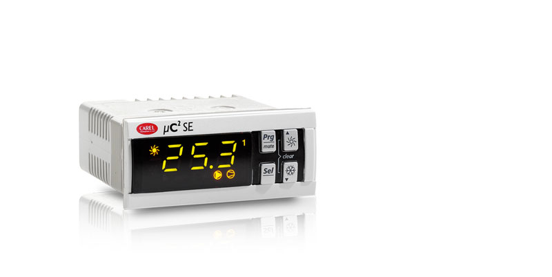
В рамках семейства µc2 компания Carel представляет параметрические контроллеры для управления холодильными машинами/тепловыми насосами с одним и двумя контурами. Все контроллеры семейства μC2SE оснащаются микропроцессором по технологии RISC и платами часов реального времени (опция), что в сумме обеспечивает выдающиеся рабочие характеристики и удобное управление. Контроллеры серии µC2 SE рассчитаны под врезной монтаж и подсоединяются кабелями с разъемами Molex®, что существенно повышает простоту и скорость монтажа, а также экономит свободное пространство.
Контроллеры серии µC2 SE предназначены для управления холодильными машинами/тепловыми насосами (типа воздух-вода и вода-вода), конденсаторными установками, установками типа воздух-воздух (прямо- и противоточными), крышными агрегатами с управлением температурой естественного охлаждения. Контроллеры могут управлять системами, насчитывающими до четырех герметичных или двух полугерметичных компрессоров, до двух контуров с одним электронным терморегулирующим вентилем (ТРВ) на каждый контур.
Преимущества
- Применение электронного терморегулирующего вентиля (ТРВ) обеспечивает точное регулирование температуры перегрева на всасывании, гарантируя более высокую энергоэффективность во всех условиях нагрузки и климатических условиях.
- Широкий выбор графических терминалов, обеспечивающих простой и удобный процесс управления контроллерами семейства µC.
Документация
Technical
-
2D/3D модели
Код Описание Язык Дата * Выпуск Код
2d — 3d mChiller2Описание
Язык
ALLДата
22/01/2019
Выпуск
R0
-
Инструкции по применению
Код Описание Язык Дата * Выпуск Код
+030220425Описание
μC2SE: controllo elettronicoЯзык
ITAДата
08/07/2019
Выпуск
2.6
Код
+030220426Описание
μC2SE: electronic controlЯзык
ENGДата
08/07/2019
Выпуск
2.6
Код
+030220427Описание
μC2SE: contrôle électroniqueЯзык
FREДата
08/07/2019
Выпуск
2.6
Код
+030220428Описание
μC2SE: Elektronische SteuerungЯзык
GERДата
08/07/2019
Выпуск
2.6
Код
+030220429Описание
μC2SE: Электронное управлениеЯзык
RUSДата
08/07/2019
Выпуск
2.6
Код
+030220424Описание
μC2SE: Controlador electrónicoЯзык
SPAДата
08/07/2019
Выпуск
2.6
Код
+030220415Описание
μC2SE per chiller di processo: Controllo elettronicoЯзык
ITAДата
17/05/2018
Выпуск
2.3
Код
+030220416Описание
μC2SE for process chiller: Electronic controllerЯзык
ENGДата
17/05/2018
Выпуск
2.3
Код
+03C220426Описание
μC2SE 电子控制器Язык
CHIДата
27/11/2012
Выпуск
2.5
Код
+030220422Описание
μC2SE: elektronický regulátorЯзык
CZEДата
27/11/2012
Выпуск
2.5
-
Руководства по эксплуатации
Код Описание Язык Дата * Выпуск Код
+050002815Описание
MCH200*03 — μC2SE: Dispositivo elettronico per controllo di chiller a 2/4 compressori (mono e bicircuito) / Electronic controller for chillers with 2/4 compressors (one and two circuits)Язык
ENG
ITAДата
03/08/2009
Выпуск
1.1
Код
+050002818Описание
MCH200*03 — μC2SE: Electronic controller for chillers with 2/4 compressors (one and two circuits) / Электронный контроллер для чилеров с 2/4 компрессорами (1 и 2 контура)Язык
ENG
RUSДата
03/08/2009
Выпуск
1.1
Код
+05C002815Описание
MCH200*03 — μC2SE: 用于带2/4压缩机的冷水机组(一个或两个回路) 控制器/ Electronic controller for chillers with 2/4 compressors (one and two circuits)Язык
CHI
ENGДата
05/08/2005
Выпуск
1.0
Commercial
-
Брошюра
Код Описание Язык Дата * Выпуск Код
+302239461Описание
Integrated solutions for ground source heat pumpsЯзык
ENGДата
01/03/2008
Выпуск
2.0
Код
+30C239461Описание
地源热泵系统控制 的整体解决方案Язык
CHIДата
01/03/2008
Выпуск
2.0
Код
+302239450Описание
Soluzioni integrate per rooftopЯзык
ITAДата
01/10/2006
Выпуск
1.0
Код
+302239451Описание
Integrated solutions for rooftop unitsЯзык
ENGДата
01/10/2006
Выпуск
1.0
Код
+302239470Описание
Soluzioni integrate per impianti idronici medio piccoliЯзык
ITAДата
01/10/2006
Выпуск
1.0
Код
+302239471Описание
Integrated solutions for small and medium hydronic systemsЯзык
ENGДата
01/10/2006
Выпуск
1.0
Код
+302239473Описание
Integrierte Lösungen für kleine und mittlere Hydronic-AnlagenЯзык
GERДата
01/10/2006
Выпуск
1.0
Код
+302239361Описание
Integrated solutions for large chillers/heat pumpsЯзык
ENGДата
01/03/2006
Выпуск
1.0
Код
+302239365Описание
Soluzioni integrate per chiller e pompe di calore di media e piccola tagliaЯзык
ITAДата
01/03/2006
Выпуск
1.0
Код
+302239366Описание
Integrated solutions for small and medium size chiller/heat pumpsЯзык
ENGДата
01/03/2006
Выпуск
1.0
Код
+302239369Описание
Комплексные решения для чиллеров/тепловых насосов малого и среднего размераЯзык
RUSДата
01/03/2006
Выпуск
1.0
Код
+302239360Описание
Soluzioni integrate chiller e pompe di calore di grossa tagliaЯзык
ITAДата
01/03/2006
Выпуск
1.0
Код
+30C239611Описание
μC sistema: 系列Язык
CHIДата
01/10/2005
Выпуск
1.0
Код
+302239611Описание
μC sistema: the rangeЯзык
ENGДата
01/10/2005
Выпуск
1.0
Код
+302239613Описание
μC sistema: Die ProduktbandbreiteЯзык
GERДата
01/10/2005
Выпуск
1.0
-
История успеха
Код Описание Язык Дата * Выпуск Код
+402200110Описание
Development of an advanced control system for chillersЯзык
ENGДата
01/03/2006
Выпуск
1.0
-
Page 1: User Manual
µC electronic control User manual…
- Page 3
CAREL or its branch offi ces/affi liates have been warned of the possibility of damage. - Page 4
µC SE — +030220426 — rel. 2.0 — 03.08.2009… -
Page 5: Table Of Contents
Content ONTENT 1. INTRODUCTION 1.1 General description ……………………..7 1.2 User interface ……………………….7 2. CONNECTIONS 2.1 General diagram ………………………9 2.2 Network layout ………………………..9 3. APPLICATIONS 3.1 Air/air unit …………………………10 3.2 AIR/AIR heat pump ……………………..11 3.3 AIR/WATER chiller ……………………..13 3.4 AIR/WATER heat pump ……………………14 3.5 WATER/WATER chiller …………………….16 3.6 WATER/WATER heat pump with reversal on gas circuit …………..17 3.7 WATER/WATER heat pump with reversal on water circuit …………19…
- Page 6
µC SE — +030220426 — rel. 2.0 — 03.08.2009… -
Page 7: Introduction
• antifreeze heater; • alarm signal device. 1.1.3 Programming CAREL offers the possibility to confi gure all the unit parameters not only from the keypad on the front panel, but also using: • a hardware key; • a serial line.
- Page 8
1.2.3 Functions associated with the buttons button unit status button press Loading default values press at power ON Go up a sub-group inside the programming area, until exiting (saving changes to EEPROM) press once In the event of alarms, mute the buzzer (if present) and deactivate the alarm relay press once Access the direct parameters press for 5 s… -
Page 9: Connections
µ expansion valve valve Optional board PSOPZKEY*: programming key CONVONOFF*: PWM/digital converter PW/Modbus ® CONV0/10A0*: PWM/analogic CAREL Supervisory MCH200485* converter NTC: temperature RS485 MCH2*T*: probes serial card terminal MCHRTF**A0: PW/Modbus ® MCH2*TSV*: SPKT: 0 to 5 V fan speed regulator…
-
Page 10: Applications
3. APPLICATIONS 3.1 Air/air unit 3.1.1 Single circuit Key: condernser fan overload condenser probe supply probe electrical heater evaporator supply fan overload supply fan compressor 1 high pressure compressor overload low pressure ambient probe compressor 2 Fig. 3.a.a 3.1.2 Two circuits Key: condernser fan overload 1 and 2 condenser probe…
-
Page 11: Air/Air Heat Pump
3.1.2 Two circuits, 1 condenser fan circuit Key: condernser fan overload condenser probe 1 and 2 supply probe electrical heater 1 and 2 evaporator 1 and 2 supply fan ambient probe compressor 1 high pressure 1 and 2 compressor overload 1 and 2 low pressure 1and 2 compressor 2 compressor 3…
- Page 12
3.2.2 Two circuits Key: condenser fan overload 1 and 2 condernser probe supply probe electrical heater 1 e 2 evaporator 1 and 2 supply fan overload supply fan compressor 1 high pressure 1 e 2 compressor overload 1 and 2 low pressure 1and 2 ambient probe compressor 2… -
Page 13: Air/Water Chiller
3.3 AIR/WATER chiller 3.3.1 Single circuit Key: condernser fan overload condenser probe fl ow switch outlet evaporator probe antifreeze heater inlet evaporator probe compressor 1 high pressure compressor overload low pressure water pump compressor 2 Fig. 3.c.a 3.3.2 two circuits, 2 condenser fan circuits and 2 evaporators Key: condenser fan overload 1 and 2 fan 1 and 2…
-
Page 14: Air/Water Heat Pump
3.3.2 two circuits, 1 condenser fan circuit Key: condenser fan overload condenser probe 1 and 2 fl ow switch outlet temperature probe evaporator 1 and 2 outlet evaporator probe 1 and 2 antifreeze heater 1 and 2 compressor 1 high pressure 1 and 2 compressor overload 1 and 2 low pressure 1and 2 inlet evaporator probe…
- Page 15
3.4.2 2 condenser fan circuits Key: condenser fan overload 1 and 2 fan 1 and 2 condenseer probe 1 and 2 fl ow switch outlet temperature probe evaporator 1 and 2 outlet evaporator probe 1 and 2 antifreeze heater 1 and 2 compressor 1 high pressure 1 and 2 compressor overload 1 and 2… -
Page 16: Water/Water Chiller
3.5 WATER/WATER chiller 3.5.1 Single circuit Key: water condensing temperature probe condensator fl ow switch outlet evaporator probe evaporator antifreeze heater inlet evaporator probe compressor 1 high pressure compressor overload low pressure water pump compressor 2 Fig. 3.e.a 3.5.2 Two circuits Key: water condensing temperature probe 1 and 2 condensator 1 and 2…
-
Page 17: Water/Water Heat Pump With Reversal On Gas Circuit
3.5.3 Ttwo circuits, 2 evaporators Key: water condensing temperature probe 1 and 2 condensator 1 and 2 fl ow switch outlet temperature probe outlet evaporator probe 1 and 2 antifreeze heater 1 and 2 evaporator water pump compressor 1 high pressure 1 and 2 compressor overload 1 and 2 low pressure 1 and 2 compressor 3…
- Page 18
3.6.2 Two circuits Key: water condensing temperature probe 1 and 2 condensator 1 and 2 fl ow switch outlet evaporator probe outlet evaporator probe 1 and 2 evaporator 1 and 2 antifreeze heater 1 and 2 water pump compressor 1 high pressure 1 and 2 compressor overload 1 and 2 low pressure 1 and 2… -
Page 19: Water/Water Heat Pump With Reversal On Water Circuit
3.7 WATER/WATER heat pump with reversal on water circuit 3.7.1 Single circuit Key: external internal reversing valve fl ow switch outlet evaporator probe antifreeze heater evaporator condenser condenser probe compressor 1 high pressure compressor overload low pressure water pump compressor 2 12 13 Fig.
-
Page 20: Air-Cooled Condensing Unit Without Reverse Cycle
3.7.3 Two circuits, 1 evaporator H02= 1 e H21= 4 Key: external internal reversing valve 1 and 2 condenser probe fl ow switch outlet evaporator probe condenser probe 1 and 2 condenser 1 and 2 outlet evaporator probe 1 and 2 antifreeze heater 1 and 2 evaporator 1 and 2 compressor 1…
-
Page 21: Reverse-Cycle Air-Cooled Condensing Unit
3.8.2 Two circuits Key: condenser fan overload condenser probe compressor 1 high pressure 1 and 2 compressor overload 1 and 2 low pressure 1 and 2 compressor 2 compressor 3 compressor 4 Fig. 3.h.b 3.9 Reverse-cycle air-cooled condensing unit 3.9.1 Single circuit Key: condenser fan overload condenser probe…
-
Page 22: Water-Cooled Condensing Unit Without Reverse Cycle
3.9.2 Two circuits with one condenser fan circuit Key: condenser fan overload condenser probe compressor 1 high pressure 1 and 2 compressor overload 1 and 2 low pressure 1 and 2 compressor 2 compressor 3 compressor 4 reversing valve Fig. 3.i.b 3.10 Water-cooled condensing unit without reverse cycle 3.10.1 Single circuit Key:…
-
Page 23: Reverse-Cycle Water-Cooled Condensing Unit
3.10.2 Two circuits Key: fl ow switch water cond. temperature probe condenser compressor 1 high pressure compressor overload lw pressure compressor 2 compressor 3 compressor 4 water pump Fig. 3.j.b 3.11 Reverse-cycle water-cooled condensing unit 3.11.1 Single circuit Key: condenser probe condenser antifreeze heater compressor 1…
-
Page 24: Roof Top Units
3.11.2 Two circuits Key: condenser probe condenser 1 and 2 antifreeze heater 1 and 2 reversing valve compressor 1 high pressure 1 and 2 compressor overload 1 and 2 low pressure 1 and 2 compressor 3 compressor 2 compressor 4 water pump Fig.
-
Page 25: Parameters
4. PARAMETERS 4.1 General parameters The parameters are divided into 4 different types, according to their level of access by the user (password) and their function. For each level, only the access to the parameters of the same or lower level can be set. This means that through “factory”…
-
Page 26: Parameter Tables
4.3 Parameter tables The following tables show of the parameters divided by type/family (e. g. compressor, probes, fans etc.). • Key to the parameter tables Level (default) S= super user F= factory D= direct Visibility: The visibility of some groups depends on the type of controller and the value of the parameters. D= defrost (if D01=1) F= fan (if F01=1) L= low noise (if F15=1-3)
- Page 27
4.3.3 Antifreeze/support heater setting parameters (A*) display parameter and description default min. max. UOM variat. default visibility supervis. Modbus variable indicat. level variable type Alarm set point antifreeze/low ambient temperature (air/air) °C/°F 11 (R/W) Analog Differential for antifreeze/low ambient temperature alarm (air/air) 1220 °C °F 12 (R/W) - Page 28
4.3.6 Defrost setting parameters (d*) display parameter and description default min. max. U.O.M. variat. default visibility supervis. Modbus variable indicat. level variable type Defrosting cycle/Condenser antifreeze Flag 7 (R/W) Digital 0= no; 1= sì, con sbrinamento unifi cato yes, with shared defrosting Time-or temperature-based defrosting Flag 90 (R/W) - Page 29
4.3.8 Unit setting parameters (H*) display parameter and description default min. max. U.O.M. variat. def. visibility supervis. Modbus variable indicat. level variable type Unit model Flag 54 (R/W) Integer 0= air_air unit 1= air_air heat pump 2= air_water chiller 3= air_water heat pump 4= water_water chiller 5= water_water heat pump with reversal on gas circuit 6= water_water heat pump with reversal on water circuit… - Page 30
4.3.9 Firmware parameters (F-r*) display parameter and description default min. max. U.O.M. variat. default visibility supervis. Modbus variable type indicat. level variable Software version, Driver 2 1 (R) Integer Software version, Driver 1 2 (R) Integer Expansion software version 3 (R) Integer Software version (displayed when powering up the 4 (R) - Page 31
4.3.11 Control setting parameters (r*) display parameter and description default min. max. U.O.M. variat. def. visibility supervis. Modbus variable indicat. level variable type Cooling set point °C/°F 12.0 41 (R/W) 41 Analog Cooling differential °C/°F 42 (R/W) 42 Analog Heating set point °C/°F 43 (R/W) 43 Analog… - Page 32
4.3.12 Timer setting parameters (t*) display parameter and description default min. max. U.M. variat. def. visibility supervis. Modbus variabile type indicat. level variable RTC hours 129(R/W) Integer RTC minutes 130 (R/W) Integer RTC day 131 (R/W) Integer RTC month mesi 132 (R/W) Integer RTC year… - Page 33
U.O.M. variat. def. visibility supervis. Modbus variable indicat. level variable type Indicates the unit parameter (Carel SV communication) Integer Gain constant for pressure probe calibration 16000 1000 Integer Offset constant for pressure probe calibration -8000 8000 Integer… - Page 34
Communication of the logical status of the digital outputs to 4200 Integer expansion: bit0= compressor bit1= compressor 4 bit2= heater 2 bit3= reversing valve bit4= warning bit5= condenser pump bit6= fans in alarm status bit7= fan status in alarm (ON= 1; ofF= 0) bit8= speed to be set (100%= 1;… -
Page 35: Description Of The Parameters
5. DESCRIPTION OF THE PARAMETERS To modify the parameters, see chapter 4 “Parameters.” • Probe settings: parameters (/*) ( see Table 4.a) — Type of probe: from /01 to /08: enables the reading of the corresponding analogue input or sets the function •…
- Page 36
A05: Differential for the activation and deactivation of the antifreeze heaters (auxiliary heaters in air/air units). CAREL NTC probe (mode H1= 2, 3, 4, 5 and 6) Operating diagram of the antifreeze alarm and the antifreeze heaters for air/water and water/water chillers and heat pumps. - Page 37
In this case, the display will be as follows: • operating mode LED OFF; • cooling heating fl ag not switched (not detected by the supervisor); • antifreeze alarm A01 (remains active even at the end of the special operation if the unit was previously ON, deactivated by manual reset or in standby). - Page 38
— Start delay between compressors c04: This sets the delay between the starts of the two compressors, so as to reduce the peak power input and make the compressors start more smoothly. The compressor LED fl ashes in this phase. •… - Page 39
— Hour counter compressor 1-2-3-4 c10, c11, c12, c13: These indicate the number of operating hours of compressor 1, 2, 3, 4, expressed in hundreds of hours. Pressing together, when the hour counter is displayed, resets the hour counter and, consequently, cancels any maintenance requests in progress. - Page 40
— Type of defrost d02: establishes the type of defrost. d02=0: the defrost has a fi xed duration that depends on d07 d02=1: the defrost starts and ends according to the temperature or pressure thresholds, see d03 and d04; d02=2: the pressure transducer and temperature probe are both located on the outside exchanger; the defrost starts when the value read by the pressure transducer is below the threshold d03 and ends when the value read by the temperature probe is above the threshold d04;… - Page 41
d10= 2: end defrost from external contact enabled therefore: • if the contact of the input is open, the end of the defrost is enabled; • if the contact of the input is closed, the defrost follows the normal procedure. d10= 3: start and end defrost from external contact enabled therefore: •… - Page 42
— Max outside temperature threshold for sliding defrost d18: This establishes the maximum value of the outside temperature below which sliding defrost is activated. — Maximum temperature/pressure differential deviation for defrost d19: This value is expressed in °C if the compensation is controlled by temperature, or in bar if controlled by pressure. - Page 43
— Maximum voltage threshold for Triac F04: In the event of fan speed control, the optional phase cutting cards (MCHRTF*) are required, fi tted with a triac. The voltage delivered by the triac to the electric fan motor corresponding to the maximum speed must be set. - Page 44
— Fan management mode in defrost F13: This parameter sets the operating logic for the condensing fans during the defrost phase: F13 = 0: (default) the fans are OFF. F13 = 1: the fans are ON as in cooling mode, based on the temperature or pressure. F13 = 2: the fans are OFF until the end defrost temperature or pressure is reached, above which they are started at maximum speed for the time set for parameter d16. - Page 45
— Number of evaporators H03: This establishes the number of evaporators present when there are 2 or 4 compressors, obviously with 2 circuits (including the expansion). With one evaporator (H03=0), the management of the heaters and the antifreeze function is performed only on B2. Vice-versa, with 2 evaporators (H03=1) antifreeze control will be performed using B2 and B6, while input B5 is used to control the water outlet temperature. - Page 46
H11= 12: associated device outputs H11=0 H11= 1 H11= 2 H11= 3 H11= 4 H11= 5 compressor 1 compressor 1 compressor 1 compressor 1 compressor 1 compressor 1 heater 1 heater 1 heater 1 reversing valve 1 reversing valve 1 heater 1 Pump/evaporator (fan) (on air/ Pump/evaporator (fan) (on air/… - Page 47
— Maximum pumpdown time H15: Maximum time after which the compressor is deactivated. — SmartSET “CAREL patent” (cannot be used on air/air units) H16: Activate smartSET, this function optimises the operation of the unit by calculating the effi ciency of the heat exchangers. - Page 48
PRG button at power ON. — select supervisor protocol H23: establishes the protocol used for the connection to the supervisor from the serial board RS485 H23 = 0: CAREL protocol (baud rate 19200,…) H23 = 1: Modbus protocol • Alarm settings: parameters (P*) — Flow switch alarm delay when starting pump P01: Establishes a delay in the recognition of the fl… - Page 49
— Alarm reset P05: Enables automatic reset for all those alarms that normally feature manual reset (high pressure, low pressure, fl ow switch/antifreeze) as per the following table: P05= 0: (default) high pressure, low pressure and antifreeze (low temperature) with manual reset; P05= 1: all the alarms with automatic reset;… - Page 50
— High temperature alarm delay on power-up P17: High temperature alarm delay when the control is switched on (power ON), from the remote ON/ OFF contact or from the keypad. — High pressure alarm from transducer set point P18: Sets the value beyond which the high pressure alarm is generated. Each circuit will be managed by its own transducer. - Page 51
When stopping, the valve is managed fi rst and then the actual compressor as a whole. Both FIFO logic and timed operation will involve either one circuit or the other. The activation and deactivation of the valves are not subject to timers, but rather only a hysteresis that is equal to the set point and the differential of the step (in fact the valve performs the same function as a hermetic compressor). - Page 52
In heating: With autotuning active and inlet control, this represents the delay from switching the compressor off to reach the outlet set point, before the next deactivation. — Compressor deactivation differential (if r06 = 4) r12: This represents the temperature differential for the deactivation of the compressors, according to the procedure described in “Deactivation time”. - Page 53
— Maximum deviation from the set point r18: Indicates the maximum deviation from the set point beyond which compensation is stopped (maximum and minimum limits in reference to the set point). — Start compensation temperature in cooling (outside probe) r19: Sets the temperature (measured by the outside probe) above which the compensation function starts (cooling), value between -40T80 °C. - Page 54
— Cooling set point in dehumidifi cation r26: Alternative set point to r01 when the dehumidifi cation function is active, as sent to the µC SE by the terminal. The differential remains the same as for chiller mode (r02). — Buffer tank suppression (low load) r27: The low load condition is determined when only one compressor is started and then is stopped after operating for less than the time set for parameter r28. - Page 55
— Enable freecooling/freeheating Example of freecooling r34: Sets the type of freecooling/heating with or without compressors r34= 0: disabled r34= 1: freecooling / without compressors / cooling only r34= 2: freecooling / with compressors / cooling only r34= 3: freeheating / without compressors / heating only r34= 4: freeheating / with compressors / heating only r34= 5: freecooling and freeheating / without compressors / freecooling in cooling only and freeheating in heating only… - Page 56
Duty cycle differential example — Damper opening duty cycle differential r37: used to calculate the duty cycle for opening the damper. — Damper closing duty cycle differential r38: used to calculate the duty cycle for closing the damper. Key: 1. opening time; Fig. - Page 57
— RTC year t05: RTC year The alarms are only shown on the local display. The controller saves the signifi cant events that stop (alarms) or limit (warnings) the operation of the unit. Up to 25 events can be saved, highlighting: —… -
Page 58: Table Of Alarms
6. TABLE OF ALARMS Key to the table of alarms: *: if the probe is set for the compensation function, in the event of probe faults, the unit continues to operate. ON*: if the expansion card is not present. EVD 1= EVD400 connected to µC SE (1st circ.) EVD 2= EVD400 connected to the expansion (2nd circ.) alarm…
- Page 59
HP1: High pressure circuit 1 The alarm is detected irrespective of the status of the pump and the compressors. The compressors corresponding to circuit 1 are immediately stopped (ignoring the set protection times), the buzzer and alarm relay are activated, and the display starts fl ashing. The fans corresponding to the condenser in circuit 1 are activated at maximum speed for 60 s, so as to oppose the alarm situation, after which they are switched OFF. - Page 60
Hc1 to Hc4: compressor operating hour limit exceeded warning When the number of operating hours for the compressor exceeds the maintenance threshold (as default equal to zero, and consequently the function is disabled), the maintenance request signal is activated. The buzzer and the alarm relay are not activated, however the warning relay is activated (with the expansion card fi… - Page 61
D1: defrost signal circuit 1 When the defrost is on circuit 1, the display shows the message D1. D2: defrost signal circuit 2 When the defrost is on circuit 2, the display shows the message D2. Fd: dirty fi lter warning This warning is only shown if the temperature difference between the exchanger inlet and outlet is higher than parameter A12. -
Page 62: Connections, Accessories And Options
7. CONNECTIONS, ACCESSORIES AND OPTIONS 7.1 Connection diagram Below is the connection diagram for the µC Panel version EV driver EV driver Line Expansion EV Driver board EV Driver tLAN No1 C1/2 C1/2 C3/4 x N02 No3 No4 C3/4 x No5 Tx/Rx GND GND B4 V+ G0 B1 B2 B3 ID5 ID3 ID1…
-
Page 63: Expansion Card
7.2 Expansion card This device allows the µC SE to manage the second refrigerant circuit on chillers, heat pumps and condensing units with up to 4 hermetic compressors. The following fi gure shows the connection diagram for the µC SE expansion card, code MCH200002*. EV Driver Line EV driver…
-
Page 64: Fan Speed Control Board (Code Mchrtf*)
7.4 Fan speed control board (code MCHRTF*) The phase cutting boards (code MCHRTF****) are used to control the speed of the condenser fans. IMPORTANT: The power supply to the µC SE (G and G0) and the MCHRTF**** board must be in phase.
-
Page 65: Programming Key (Code Psopzkeya0)
Warning: the copying of the parameters is allowed only between instruments with the same code. Data loading operation to the key is always allowed. To make identifi cation of the key easier CAREL has inserted a label on which you can describe the loaded programming or the machine to which you are Fig.
-
Page 66: Rs485 Serial Options
7.9 RS485 serial options RS485 serial option for µC SE panel version (code MCH2004850) The MCH2004850 serial option is used to connect the µC SE controller to a supervisor network via a standard RS485 serial line. This option uses the input normally associated with the programming key, which has the dual function of key connector/serial communication port.
-
Page 67: Dimensions
8. DIMENSIONS The following are the mechanical dimensions of each component in the µC SE controller; all the values are expressed in millimetres. Note: the dimensions include the free connectors inserted. MCH200000* µC SE panel mounting version drilling template 71×29 mm com p x10 0 panel mounting…
- Page 68
MCHRTF series single-phase speed controllers Model A (component side) B MCHRTF04C0 MCHRTF08C0 MCHRTF12C0 Note: the version with screw teminals code MCHRTF*D0 is available on request Table 8.a 8 e 12 A Fig. 8.e Model MCHRTF10C0 Table 8.b 74.5 12.5 Ø 4 74.5 12.5 Fig. -
Page 69: Codes
B1, B2, B3, B4: NTC CAREL temperature probes (10 kW at 25 °C) Fig. 10.a The response time depends on the component used, typical value 90 s B4: NTC temp. probes (10 kW at 25 °C) or CAREL 0 to 5 V ratiometric pressure probes SPKT00**R* Fan output…
-
Page 70: Software Updates
The error in the converted value may vary according to the settings of parameters /9, /10, /11, /12 Table 10.b Characteristics of the connectors The connectors may be purchased using CAREL code (MCHCON0***) or from the manufacturer Molex ® Molex ®…
- Page 72
Agence/Agency: CAREL INDUSTRIES HQs Via dell’Industria, 11 — 35020 Brugine — Padova (Italy) Tel. (+39) 049.9716611 — Fax (+39) 049.9716600 e-mail: carel@carel.com — www.carel.com…