- Manuals
- Brands
- LAUMAS Manuals
- Accessories
- W100
- Installation and user manual
-
Contents
-
Table of Contents
-
Bookmarks
Quick Links
ENGLISH
ENGLISH
ENGLISH
ENGLISH
Installation and User Manual
version 1.07
W100 – W100ANA
2014/30/EU
EN55022:2010 EN61000-6-2:2005 EN61000-6-4:2007
SYSTEM IDENTIFICATION
Related Manuals for LAUMAS W100
Summary of Contents for LAUMAS W100
-
Page 1
ENGLISH ENGLISH ENGLISH ENGLISH Installation and User Manual version 1.07 W100 – W100ANA 2014/30/EU EN55022:2010 EN61000-6-2:2005 EN61000-6-4:2007 SYSTEM IDENTIFICATION… -
Page 2
No guarantee against misuse. Batteries: Laumas provides 1 year guarantee from the date of delivery note, against material defects or battery manufacturing faults. Disposal of Waste Equipment by Users in Private Households in the European Union This symbol on the product or on its packaging indicates that this product must not be disposed of with your other household waste. -
Page 3: Table Of Contents
TABLE OF CONTENTS USER WARNINGS ……………………1 RECOMMENDATIONS FOR CORRECT INSTALLATION OF WEIGHING INSTRUMENTS . 1 RECOMMENDATIONS FOR CORRECT INSTALLATION OF THE LOAD CELLS ….1 LOAD CELL INPUT TEST (QUICK ACCESS) …………….3 LOAD CELL TESTING ………………….. 3 …
-
Page 4
RS485 CONNECTION ……………………25 RS232 CONNECTION ……………………26 COMMUNICATION SETTING ………………….26 WEIMOD MODE ……………………..27 WEIRIP MODE ……………………..27 TEST ……………………….28 DATE AND TIME SETTING ………………… 28 INFO MENU ……………………..28 … -
Page 5: User Warnings
USER WARNINGS RECOMMENDATIONS FOR THE PROPER USE OF WEIGHING INSTRUMENT Keep away from heat sources and direct sunlight Repair the instrument from rain (except special IP versions) Do not wash with water jets (except special IP versions) Do not dip in water Do not spill liquid on the instrument Do not use solvents to clean the instrument Do not install in areas subject to explosion hazard (except special Atex versions)
-
Page 6
CONNECTING SEVERAL CELLS IN PARALLEL: Connect several cells in parallel by using — if necessary — a watertight junction box with terminal box. The cell connection extension cables must be shielded, led individually into their piping or conduit and laid as far as possible from the power cables (in case of 4-wire connections, use cables with 4×1 mm minimum cross-section). -
Page 7: Load Cell Input Test (Quick Access)
LOAD CELL INPUT TEST (QUICK ACCESS) From the weight display, press ▲ for 3 seconds; the response signal of the load cells is displayed, expressed in mV with four decimals. LOAD CELL TESTING Load cell resistance measurement (use a digital multimeter): — Disconnect the load cells from the instrument and check that there is no moisture in the cell junction box caused by condensation or water infiltration.
-
Page 8: Main Specifications Of The Instrument
Two serial ports (RS485 and RS232) for connection to: PC/PLC up to 32 instruments (max 99 with line repeaters) by ASCII Laumas or ModBus R.T.U. protocol, remote display, printer. The instrument can be connected to a CLM serie intelligent junction box or to a multi-channel weight transmitter.
-
Page 9: Technical Specifications
TECHNICAL SPECIFICATIONS POWER SUPPLY and CONSUMPTION (VDC) 12/24 VDC ±10%; 5 W NO. OF LOAD CELLS IN PARALLEL and SUPPLY max 8 (350 ohm); 5 VDC / 120 mA LINEARITY / ANALOG OUTPUT LINEARITY < 0.01% F.S.; < 0.01% F.S. THERMAL DRIFT / ANALOG OUTPUT THERMAL DRIFT <…
-
Page 10: Electrical Connections
ELECTRICAL CONNECTIONS TERMINALS LEGEND +SUPPLY (12/24 VDC) -SUPPLY (12/24 VDC) INPUT No. 3 (+VDC min 5 V max 24 V) RS232, RS485: SHIELD, GND otherwise: E/EC OPTION: GND +ANALOG OUTPUT 0÷20 or 4÷20 mA OUTPUT No. 5 RS232: TXD otherwise: +ANALOG OUTPUT 0÷10 V E/EC OPTION RS232: RXD…
-
Page 11: Wiring Diagram
WIRING DIAGRAM OUTPUTS INPUTS E OPTION 12/24 VDC max 115 VAC supply supply 150 mA 5÷24 VDC 4 5 6 7 9 10 RS232 Buttons not included in the supply EC OPTION 2 3 4 5 6 to instrument (1) ANALOG OUTPUT OPTION 14 15 14 15…
-
Page 12: Led And Key Function
LED AND KEY FUNCTION Main function Secondary function * net weight (semi-automatic tare or preset tare) LED lit: input 1 closed zero (deviation from zero not more than ±0.25 divisions) LED lit: input 2 closed stability LED lit: input 3 closed unit of measure: kg LED lit: output 4 closed unit of measure: g…
-
Page 13: Menu Map
MENU MAP Into menus changes are applied right after pressing the ENTER key (no further confirmation is required). SETPOINT … … … SYSTEM PARAMETERS …
-
Page 14: Instrument Commissioning
INSTRUMENT COMMISSIONING Upon switch-on, the display shows in sequence: — → (ONLY in case of approved program); — instrument model (e.g.: ); — followed by the software code (e.g.: ); — program type: (base); — followed by the software version (e.g.: ); — …
-
Page 15: Programming Of System Parameters
PROGRAMMING OF SYSTEM PARAMETERS From the weight display, press simultaneously keys MENU and ESC to access the parameter setting. MENU/ENTER: to enter a menu/confirm the data entry. ▲: to modify the displayed figure or menu item. ◄: to select a new figure or modify the displayed menu item. ESC: to cancel and return to the previous menu.
-
Page 16: Maximum Capacity
MAXIMUM CAPACITY : Maximum displayable weight (from 0 to max full scale; default: 0). When the weight exceeds this value by 9 divisions, the display shows . To disable this function, set 0. TARE WEIGHT ZERO SETTING …
-
Page 17: Filter On The Weight
By confirming the message the flashing value of the weight currently on the system is displayed. In this phase all of the LEDs are off. Adjust the value on display by using the arrow keys if necessary. After confirming, the new set weight will appear with all the LEDs flashing. After an additional confirmation, the message …
-
Page 18: Anti Peak
The filter enables to stabilise a weight as long as its variations are smaller than the corresponding “response time”. It is necessary to set this filter according to the type of application and to the full scale value set. FILTER VALUE Response times Display and serial port refresh [ms]…
-
Page 19: Automatic Zero Setting At Power-On
AUTOMATIC ZERO SETTING AT POWER-ON (from 0 to max 20% of full scale; default: 0): If at switch-on the weight value is lower than the value set in this parameter and does not exceed the value, the weight is reset. To disable this function, set 0.
-
Page 20: Display Coefficient
DISPLAY COEFFICIENT By setting the coefficient the display is changed accordingly. If one of the inputs is set to mode (see section OUTPUTS AND INPUTS CONFIGURATION) when the input is closed the value will be displayed modified according to the …
-
Page 21: Outputs And Inputs Configuration
REAL CALIBRATION’S CHANGE FOR OTHER UNITS OF MEASURE Load a known quantity of product litres on the scale (equal to at least 50% of the maximum amount that you must weigh) and enter in the parameter , the product loaded value in litres. Also, if you set the parameter …
-
Page 22: Semi-Automatic Tare (Net/Gross)
— setpoint = 0 and switching = : relay switching occurs for a weight higher than or equal to 0, the relay will switch again for values below 0, taking hysteresis into account. — setpoint = 0 and switching = : relay switching occurs for a weight lower than or equal to 0, the relay will switch again for values above 0, taking hysteresis into account.
-
Page 23: Preset Tare (Subtractive Tare Device)
Example: Put the box on the scale, the display shows the box weight; press TARE, the display shows the net weight to zero; introduce the product in the box, the display shows the product weight. This operation can be repeated several times. While the net weight is displayed, keep ▲…
-
Page 24: Semi-Automatic Zero (Weight Zero-Setting For Small Variations)
SEMI-AUTOMATIC ZERO (WEIGHT ZERO-SETTING FOR SMALL VARIATIONS) By closing the SEMI-AUTOMATIC ZERO input, the weight is set to zero; alternatively, by pressing key for less than 3 seconds, the message is displayed for 3 seconds, by pressing ENTER the weight is set to zero. This function is only allowed if the weight is lower than the …
-
Page 25
— : choice of a weight followed by the analog output: gross () or net (). If the net function is not active, the analog output varies according to gross weight. — : set the weight value for which you wish to obtain the minimum analog output value. Only set a value different from zero if you wish to limit the analog output range;… -
Page 26: Serial Communication Setting
All analog outputs of the instrument are ACTIVE and SINGLE ENDED type, therefore they can be connected only to PASSIVE receiver devices. The minimum load allowed for voltage outputs is 10 kohm, the maximum load allowed for current outputs is 300 ohm. Voltage or current analog signal ACTIVE PASSIVE…
-
Page 27
— : weight reception mode (see section WEIGHT READING VIA SERIAL PORT). — : weight reception mode (see section WEIGHT READING VIA SERIAL PORT). — : transmission speed (2400, 4800, 9600, 19200, 38400, 115200; default: 9600). — : instrument address (from 1 to 99; default: 1). — : maximum transmission frequency (10 –… -
Page 28: Rs232 Serial Communication
RS232 SERIAL COMMUNICATION INSTRUMENT RS232 TXD RS232 RXD DB9-F RS485 SERIAL COMMUNICATION INSTRUMENT INSTRUMENT INSTRUMENT max 500 m 24 VDC RS485 + RS485 + RS485 — RS485 — CONVLAU If the RS485 network exceeds 100 metres in length or baud-rate over 9600 are used, two terminating resistors are needed at the ends of the network.
-
Page 29: Weight Reading Via Serial Port
Receiving instrument INSTRUMENT Connector Signal RS485: — W100 TERMINAL RS485: + RS485: SHIELD, GND If the RS485 network exceeds 100 metres in length or baud-rate is higher than 9600, two terminating resistors are needed at the ends of the network. Two 120 ohm resistors are to be connected, between the “+”…
-
Page 30: Rs232 Connection
Receiving instrument TX RX INSTRUMENT Connector Signal RS232: TXD W100 TERMINAL RS232: RXD RS232: SHIELD, GND COMMUNICATION SETTING Into the SERIAL COMMUNICATION SETTING section (see receiving instrument manual), select the desired serial port and operation mode: WEIRIP () or WEIMOD ().
-
Page 31: Weimod Mode
WEIMOD MODE Receiving instrument works as if the load cell is directly connected to the instrument. It’s therefore possible to perform calibrations and zero-settings on the receiving instrument. The used protocol is Modbus (the transmitting instrument works as «slave» and the receiving as «master»). Prior to set the …
-
Page 32: Test
TEST — Input Test: : ensure that for each open input is displayed, is displayed when the input is closed. — Output Test: : setting ensure that the corresponding output opens. Setting ensure that the corresponding output closes.
-
Page 33: Setpoint Programming
SETPOINT PROGRAMMING From the weight display, press MENU to access the setpoint setting. MENU/ENTER: to enter a menu/confirm the data entry. ▲: to modify the displayed figure or menu item. ◄: to select a new figure or modify the displayed menu item. ESC: to cancel and return to the previous menu.
-
Page 34: Alarms
ALARMS : the load cell is not connected or is incorrectly connected; the load cell signal exceeds 39 mV; the conversion electronics (AD converter) is malfunctioning; the load cell is a 4- wire and there are no jumpers between EX- and REF- and between EX+ and REF+. : communication problems between transmitter and receiver;…
-
Page 35
Serial protocol alarms: MODE The response to the Bit LSB 76543210 76543210 76543210 76543210 76543210 zero command is a On gross: xxxxxxx1 xxxx1xxx xxxxxx1x xxxxx1xx Status ‘value not valid’ error xxx1xxxx Register (error code 3) On net: MODBUS RTU xx1xxxxx… -
Page 36: Printing Examples
PRINTING EXAMPLES If the printer has been set (see section SERIAL COMMUNICATION SETTINGS), from the weight display press the PRINT key for less than 3 seconds: BASIC PRINTOUT ———————— W100 BASE Addr:01 DATE: 12/09/11 14:48:12 GROSS 878 kg 589 kg…
-
Page 37: Reserved For The Installer
RESERVED FOR THE INSTALLER MENU LOCKING Through this procedure, it’s possible to block the access to any menu on the instrument. Select the menu that you wish to lock: press ESC and ◄ simultaneously for 3 seconds, the display shows …
-
Page 38: Keypad Or Display Locking
PROGRAM SELECTION: confirm and use the arrow keys to select the desired program: : basic program, setpoint management only. : to be used when the loaded weighing system correspond to not loaded cells and vice versa (product increases while weight on load cells actually decreases). : weight remote display program with setpoint.
-
Page 39: Declaration Of Conformity — Eu
CERTIFICAZIONE DEL SISTEMA DI GARANZIA DELLA QUALITÀ DELLA PRODUZIONE email: laumas@laumas.it web: http://www.laumas.com LAUMAS Elettronica S.r.l. Tel. (+39) 0521 683124 — Fax (+39) 0521 681091 Fabbricante metrico Prot. N. 7340 Parma — R.E.A. PR N. 169833 — Reg. Imprese Via 1° Maggio 6 – 43022 Montechiarugolo (PR) Italy PR N.19393 — Registro Nazionale Pile N°…
This manual is also suitable for:
W100ana
- Главная
- Продукция
- Весоизмерительные приборы
- Индикаторы веса
- W100
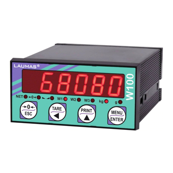
GENERAL FEATURES
Weight Indicator in DIN case, dimensions 48 x 96 x 130 mm. IP54 front panel protection. Four-key membrane keyboard. Eight indicator led. Real time clock/calendar.
- Panel mounting
- Six-digit red LED display, 14 mm height
- RS232 and RS485 ports (Modbus RTU/Laumas ASCII protocol)
- 3 logic inputs, 5 relay outputs
- OIML R76:2006 approved, class III, 10000 divis. 0.2μV/VSI
- OIML R61 approved — WELMEC Guide 8.8:2011 (M.I.D.)
- A/D converter 24bit (16000000 points) 4.8 kHz
- Display range 999999
Some optional features:
- 16-bit Analog output: 0/4-20 mA; 0-5/10 V; ±5/10 V
DOWNLOAD
Check which documents are available in other languages.
Руководства и листы продуктов
![]() Manual
Manual
![]() CE-M approved legal for trade — installer manual
CE-M approved legal for trade — installer manual
![]() CE-M approved legal for trade — user manual
CE-M approved legal for trade — user manual
![]() Options for series W — manual
Options for series W — manual
![]() Protocols for series W — manual
Protocols for series W — manual
![]() Protocols for series W CE-M approved — manual
Protocols for series W CE-M approved — manual
Прейскуранты
![]() Data sheet with prices
Data sheet with prices
Сертификаты
![]() NTEP Certificate of Conformity – United States
NTEP Certificate of Conformity – United States
![]() “Weight and Measures Regulations 1999” Certificate — New Zealand
“Weight and Measures Regulations 1999” Certificate — New Zealand
![]() EU Type Examination Certificate (NAWI)
EU Type Examination Certificate (NAWI)
![]() UL/CSA Certificate of Conformity – Unites States and Canada
UL/CSA Certificate of Conformity – Unites States and Canada
![]() NMI R 76 (NAWI) Certificate — Australia
NMI R 76 (NAWI) Certificate — Australia
![]() MID OIML R 61 Evaluation Certificate
MID OIML R 61 Evaluation Certificate
![]() Pattern Approval Certificate (PAC ) – Russian Federation
Pattern Approval Certificate (PAC ) – Russian Federation
![]() UK Type Examination Certificate (NAWI) — United Kingdom
UK Type Examination Certificate (NAWI) — United Kingdom
![]() OIML R 76 Certificate (NAWI)
OIML R 76 Certificate (NAWI)
![]() Chinese Pattern Approval Certificate (CPA) — W Series — standard version
Chinese Pattern Approval Certificate (CPA) — W Series — standard version
Чертежи CAD
![]() W100 — 3D model
W100 — 3D model
Соответствующие коды артикула
JOLLYW100, JOLLYW100ANA, JOLLYW100ING010, JOLLYW100ING420, OEMW100, OEMW100ANA, OPZW1ANALOGICA, OPZW1RS485, OPZW48X96IP65, OPZWAEC, OPZWALIBI, OPZWALIBI2, OPZWING010, OPZWING420, W100ANA, W100RIP, W60000ANA, W60000ANAPC, W60000ANAREV, W60000CANA, W60000SANA
ПОХОЖИЕ ТОВАРЫ
Below are the symbols used in the manual to draw the reader’s attention:
Warning! Risk of electrocution.
Warning! This operation must be performed by skilled workers.
Read the following indications carefully.
Further information.
GUARANTEE
24 months from the delivery document date. The guarantee covers only defected parts and includes the replacement parts and
labour. All shipping and packing costs are paid by the customer. It is possible to have the repair in guarantee on condition that the
returned product has not been transformed, damaged or repaired without authorization. No guarantee is applicable on returned
products without the original label and/or serial number. No guarantee against misuse.
Batteries: Laumas provides 1 year guarantee from the date of delivery note, against material defects or battery manufacturing faults.
Disposal of Waste Equipment by Users in Private Households in the European Union
This symbol on the product or on its packaging indicates that this product must not be disposed of with
your other household waste. It is your responsibility to dispose of your waste equipment by handing it
over to a designated collection point for the recycling of waste electrical and electronic equipment. The
separate collection and recycling of your waste equipment at the time of disposal will help preserve
natural resources and protect human health and the environment. For more information about where you
can drop off your waste equipment for recycling, please contact your local waste disposal Authority or
the equipment retailer.
KEY TO SYMBOLS
Similar to LAUMAS W100 Manuals, User Guides and Instructions:
-
camry CR 4702
(GB) (F) mode d’emploi (E) manual de uso(P) manual de serviço (LT) naudojimo instrukcija (LV) lietošanas instrukcija (EST kasutusjuhend(RO) Instrucţiunea de deservire (BIH) upute za uporabu(HU) felhasználói kézikönyv (FI) käyttöopas(PL) instrukcja obsługiuser manual (D) bedienungsanweisung CR 4702 …
CR 4702 Kitchen Appliances, 5
-
Bosch PLS
© Bosch Connected Devices and Solutions GmbH 2021. All rights reserved, also regarding any disposal, exploitation, reproduction, editing, distribution, as well as in the event of application for industrial property rights. Parking Lot Sensor | PLS 1 | 18 User manual Parking Lot Sensor | PLS User manual 1.5 …
PLS Kitchen Appliances, 18
-
Elko Inels Air AirQS-100NB
1 / 4L NAirQS-100NB02-60/2019 Rev.: 013116555542222L N784a)b)3L NLN12ELKO EP, s.r.o. Palackého 493769 01 Holešov, VšetulyCzech Republic Tel.: +420 573 514 211e-mail: [email protected] DescriptionENMade in Czech Republic• AirQS-100 — monitors the CO2 content of the r …
Inels Air AirQS-100NB Kitchen Appliances, 4
-
E+E Elektronik EE75
BEDIENUNGSANLEITUNG EE75 USB — SchnittstellenkabelMANUAL EE75USB — interface cableLangwiesen 7A-4209 EngerwitzdorfAustriaT: +43-7235-605-0 F: +43-7235-605-8E: [email protected] www.epluse.com1. Belegung USB — Schnittstellenkabel / Assignment USB — interface cable:Litzenfarbe / colour of wire: Signal / signal: Terminal Nr …
EE75 Cables and connectors, 2
-
Emos P5741
1P5741GBWireless doorchimeCZBezdrátový zvonekSKBezdrôtový zvončekPLDzwonek bezprzewodowyHUVezeték nélküli csengőSIBrezžični zvonecRS|HR|BABežično zvonoDEFunkklingelUAБездротовий дзвінок ROSonerie fără rLTBelaidis durų skambutisLVBezvadu durvju zvans3402041000_31-P5741 80 × 120 mmw …
P5741 Kitchen Appliances, 36