- Manuals
- Brands
- LAUMAS Manuals
- Accessories
- W200BOX
- Installation and user manual
-
Contents
-
Table of Contents
-
Bookmarks
Quick Links
ENGLISH
ENGLISH
ENGLISH
ENGLISH
Installation and User Manual
version 1.07
W200
Base
2014/30/EU
EN55022:2010 EN61000-6-2:2005 EN61000-6-4:2007
SYSTEM IDENTIFICATION
Related Manuals for LAUMAS W200BOX
Summary of Contents for LAUMAS W200BOX
-
Page 1
ENGLISH ENGLISH ENGLISH ENGLISH Installation and User Manual version 1.07 W200 Base 2014/30/EU EN55022:2010 EN61000-6-2:2005 EN61000-6-4:2007 SYSTEM IDENTIFICATION… -
Page 2
No guarantee against misuse. Batteries: Laumas provides 1 year guarantee from the date of delivery note, against material defects or battery manufacturing faults. Disposal of Waste Equipment by Users in Private Households in the European Union This symbol on the product or on its packaging indicates that this product must not be disposed of with your other household waste. -
Page 3: Table Of Contents
TABLE OF CONTENTS USER WARNINGS ……………………. 1 RECOMMENDATIONS FOR CORRECT INSTALLATION OF WEIGHING INSTRUMENTS . 1 RECOMMENDATIONS FOR CORRECT INSTALLATION OF THE LOAD CELLS ….1 LOAD CELL INPUT TEST (QUICK ACCESS) …………….. 3 LOAD CELL TESTING ………………….3 MAIN SPECIFICATIONS OF THE INSTRUMENT…………..4 BUFFER BATTERY ……………………
-
Page 4
WEIGHT READING VIA SERIAL PORT …………….26 RS485 CONNECTION ……………………26 RS232 CONNECTION ……………………27 COMMUNICATION SETTING ………………….27 WEIMOD MODE ……………………..28 WEIRIP MODE ……………………..28 TEST ……………………….28 DATE AND TIME SETTING ………………..29 INFO MENU ……………………..29 SETPOINT PROGRAMMING ……………….. -
Page 5: User Warnings
USER WARNINGS RECOMMENDATIONS FOR THE PROPER USE OF WEIGHING INSTRUMENT Keep away from heat sources and direct sunlight Repair the instrument from rain (except special IP versions) Do not wash with water jets (except special IP versions) Do not dip in water Do not spill liquid on the instrument Do not use solvents to clean the instrument Do not install in areas subject to explosion hazard (except special Atex versions)
-
Page 6
CONNECTING SEVERAL CELLS IN PARALLEL: Connect several cells in parallel by using — if necessary — a watertight junction box with terminal box. The cell connection extension cables must be shielded, led individually into their piping or conduit and laid as far as possible from the power cables (in case of 4-wire connections, use cables with 4×1 mm minimum cross-section). -
Page 7: Load Cell Input Test (Quick Access)
LOAD CELL INPUT TEST (QUICK ACCESS) From the weight display, press ▲ for 3 seconds; the response signal of the load cells is displayed, expressed in mV with four decimals. LOAD CELL TESTING Load cell resistance measurement (use a digital multimeter): — Disconnect the load cells from the instrument and check that there is no moisture in the cell junction box caused by condensation or water infiltration.
-
Page 8: Main Specifications Of The Instrument
14 mm, 7 segments; 8 indicator LEDs. 5−key membrane keypad with buzzer. Real-time clock/calendar with buffer battery. W200BOX — IP67 waterproof ABS box version: dimensions 170x140x95 mm; four fixing holes Ø 4 mm (centre distance 152×122 mm). W200 IP67 — IP67 waterproof polycarbonate box version: dimensions 180x130x77 mm, four fixing holes Ø…
-
Page 9: Technical Specifications
TECHNICAL SPECIFICATIONS POWER SUPPLY and CONSUMPTION (VDC) 12/24 VDC ±10%; 5 W (standard) POWER SUPPLY and CONSUMPTION (VAC) 115/230 VAC (optional); 50-60 Hz; 6 VA NO. OF LOAD CELLS IN PARALLEL and SUPPLY max 8 (350 ohm); 5 VDC / 120 mA LINEARITY / ANALOG OUTPUT LINEARITY <…
-
Page 10: Electrical Connections
ELECTRICAL CONNECTIONS TERMINALS LEGEND +SUPPLY (12/24 VDC) OUTPUT No. 5 otherwise: 115/230 VAC optional version: +ANALOG OUTPUT (0÷10 V) +OUTPUT (24 VDC) -SUPPLY (12/24 VDC) RS232, RS485: SHIELD, GND E/EC OPTION: GND E/EC OPTION otherwise: 115/230 VAC optional version: -ANALOG OUTPUT COMMON -OUTPUT (24 VDC) RS232, RS485: SHIELD, GND E/EC OPTION: GND…
-
Page 11: Wiring Diagram
WIRING DIAGRAM OUTPUTS INPUTS E OPTION 12/24 VDC supply max 115 VAC supply 150 mA 5÷24 VDC 4 5 6 7 9 10 RS232 Buttons not included in the supply EC OPTION to instrument 2 3 4 5 6 (1) ANALOG OUTPUT OPTION 14 15 14 15…
-
Page 12: Led And Key Function
LED AND KEY FUNCTION Main function Secondary function * net weight (semi-automatic tare or preset tare) LED lit: input 1 closed zero (deviation from zero not more than ±0.25 divisions) LED lit: input 2 closed stability LED lit: input 3 closed unit of measure: kg LED lit: output 4 closed unit of measure: g…
-
Page 13: Menu Map
MENU MAP Into menus changes are applied right after pressing the ENTER key ( no further confirmation is required). SETPOINT … … … SYSTEM PARAMETERS …
-
Page 14: Instrument Commissioning
INSTRUMENT COMMISSIONING Upon switch-on, the display shows in sequence: — → (ONLY in case of approved program); — instrument model (e.g.: ); — followed by the software code (e.g.: ); — program type: (base); — followed by the software version (e.g.: ); — …
-
Page 15: Programming Of System Parameters
PROGRAMMING OF SYSTEM PARAMETERS From the weight display, press simultaneously keys MENU and ESC to access the parameter setting. MENU/ENTER: to enter a menu/confirm the data entry. ▲: to modify the displayed figure or menu item. ◄: to select a new figure or modify the displayed menu item. ESC: to cancel and return to the previous menu.
-
Page 16: Maximum Capacity
MAXIMUM CAPACITY : Maximum displayable weight (from 0 to max full scale; default: 0). When the weight exceeds this value by 9 divisions, the display shows . To disable this function, set 0. TARE WEIGHT ZERO SETTING …
-
Page 17: Real Calibration (With Sample Weights)
REAL CALIBRATION (WITH SAMPLE WEIGHTS) After having performed the THEORETICAL CALIBRATION and TARE WEIGHT ZERO SETTING, this function allows correct calibration to be done using sample weights of known value and, if necessary, any deviations of the indicated value from the correct value to be corrected.
-
Page 18: Filter On The Weight
FILTER ON THE WEIGHT Setting this parameter allows a stable weight display to be obtained. To increase the effect (weight more stable) increase the value (from 0 to 9, default 4). As seen in the diagram: — By confirming the message, the currently programmed filter value is displayed. — By changing and confirming the value, the weight is displayed and it will be possible to experimentally verify its stability.
-
Page 19: Zero Parameters
ZERO PARAMETERS RESETTABLE WEIGHT SETTING FOR SMALL WEIGHT CHANGES (from 0 to max full scale; default: 300; considered decimals: 300 – 30.0 – 3.00 – 0.300): this parameter indicates the maximum weight value resettable by external contact, keypad or serial protocol.
-
Page 20: Setting Units Of Measure
SETTING UNITS OF MEASURE These are the available units of measure: kilograms : grams : tons : : pounds* : newtons* litres* : bars* : atmospheres* : : pieces* newton metres* : : kilogram metres* other generic units of measure not included in the list* : If the print function is enabled, the symbol corresponding to the selected unit of measure will be printed after the measured value.
-
Page 21
: pieces, in set the weight of one piece; : newton metres, the value set in will be multiplied by the weight value currently displayed; : kilogram metres, the value set in will be multiplied by the weight value currently displayed;… -
Page 22: Outputs And Inputs Configuration
OUTPUTS AND INPUTS CONFIGURATION … … OUTPUTS The outputs are set by default as follows: / / / / . Possible operation modes: — (normally open): the relay is de-energised and the contact is open when the weight is lower than the programmed setpoint value;…
-
Page 23: Semi-Automatic Tare (Net/Gross)
INPUTS Default: input 1 = input 2 = input 3 = Possible operation modes: — (NET/GROSS): by closing this input for no more than one second, it’s making an operation of SEMI-AUTOMATIC TARE and the display will show the net weight. To display the gross weight again, hold the NET/GROSS input closed for 3 seconds.
-
Page 24: Preset Tare (Subtractive Tare Device)
PRESET TARE (SUBTRACTIVE TARE DEVICE) It is possible to manually set a preset tare value to be subtracted from the display value provided that the ≤ max capacity condition is verified. By default the instrument shows the last programmed preset tare value: to apply it press ▲ and then ENTER.
-
Page 25: Peak
PEAK By keeping the PEAK input closed the maximum weight value reached remains displayed. By opening the input the current weight is displayed. If you wish to use this input to view a sudden variation peak, set the FILTER ON THE WEIGHT to 0.
-
Page 26
— : analog output correction to zero: if necessary adjust the analog output, allowing the PLC to indicate 0. The sign “-“ can be set for the last digit on the left. E.g.: if I use a 4÷20 mA output and, with the minimum analog setting, the PLC or tester read 4.1 mA, I must set the parameter to 3.9 to obtain 4.0 on the PLC or tester. -
Page 27: Serial Communication Setting
SERIAL COMMUNICATION SETTING — / : communication port. — : it disables any type of communication (default). — : MODBUS-RTU protocol; possible addresses: from 1 to 99 (see Communication protocols manual). — : ASCII bidirectional protocol; possible addresses: from 1 to 99 (see Communication protocols manual).
-
Page 28
— : maximum transmission frequency (10 – 20 – 30 – 40 – 50 – 60 – 70 – 80 – 100 – 200 – 300; default: 10); o be set when the transmission protocol is selected. Maximum setting frequency (): — 20 Hz with minimum baud rate 2400 baud. -
Page 29: Rs232 Serial Communication
RS232 SERIAL COMMUNICATION INSTRUMENT RS232 TXD RS232 RXD DB9-F RS485 SERIAL COMMUNICATION INSTRUMENT INSTRUMENT INSTRUMENT max 500 m 24 VDC RS485 + RS485 + RS485 — RS485 — CONVLAU If the RS485 network exceeds 100 metres in length or baud-rate over 9600 are used, two terminating resistors are needed at the ends of the network.
-
Page 30: Weight Reading Via Serial Port
RS485: — W200 TERMINAL RS485: + W200BOX RS485: SHIELD, GND If the RS485 network exceeds 100 metres in length or baud-rate is higher than 9600, two terminating resistors are needed at the ends of the network. Two 120 ohm resistors are to be connected, between the “+”…
-
Page 31: Rs232 Connection
Signal RS232: TXD W200 TERMINAL RS232: RXD W200BOX RS232: SHIELD, GND COMMUNICATION SETTING Into the SERIAL COMMUNICATION SETTING section (see receiving instrument manual), select the desired serial port and operation mode: WEIRIP () or WEIMOD (). It’s not possible to enable this function on both serial ports; in case of conflict, the last serial set, remains active.
-
Page 32: Weimod Mode
WEIMOD MODE Receiving instrument works as if the load cell is directly connected to the instrument. It’s therefore possible to perform calibrations and zero-settings on the receiving instrument. The used protocol is Modbus (the transmitting instrument works as «slave» and the receiving as «master»). Prior to set the …
-
Page 33: Date And Time Setting
— Millivolt Test: : displays the load cell response signal in mV with four decimals. DATE AND TIME SETTING Selecting the item in the main menu, access is obtained to the date and time display menu. Pressing ENTER several times scrolls through days — months –…
-
Page 34: Alarms
— (from 0 to max full scale; default: 0): Hysteresis, value to be subtracted from the setpoint to obtain contact switching for decreasing weight. For example with a setpoint at 100 and hysteresis at 10, the switching occurs at 90 for decreasing weight. These values are set to zero if the calibration is changed significantly (see sections THEORETICAL CALIBRATION and REAL CALIBRATION (WITH SAMPLE WEIGHTS)).
-
Page 35
Serial protocol alarms: MODE The response to the Bit LSB 76543210 76543210 76543210 76543210 76543210 zero command is a On gross: xxxxxxx1 xxxx1xxx xxxxxx1x xxxxx1xx Status ‘value not valid’ error xxx1xxxx Register (error code 3) On net:… -
Page 36: Printing Examples
PRINTING EXAMPLES If the printer has been set (see section SERIAL COMMUNICATION SETTINGS), from the weight display press the PRINT key for less than 3 seconds: BASIC PRINTOUT ———————— W200 BASE Addr:01 DATE: 12/09/11 14:48:12 GROSS 878 kg 589 kg TARE 289 kg BASIC PRINTOUT (PEAK ENABLED):…
-
Page 37: Reserved For The Installer
RESERVED FOR THE INSTALLER MENU LOCKING Through this procedure, it’s possible to block the access to any menu on the instrument. Select the menu that you wish to lock: press ESC and ◄ simultaneously for 3 seconds, the display shows …
-
Page 38: Keypad Or Display Locking
PROGRAM SELECTION: confirm and use the arrow keys to select the desired program: : basic program, setpoint management only. : to be used when the loaded weighing system correspond to not loaded cells and vice versa (product increases while weight on load cells actually decreases). : weight remote display program with setpoint.
-
Page 39: Declaration Of Conformity — Eu
Niniejszym oświadczamy, że produkt, którego niniejsze oświadczenie dotyczy, jest zgodny z Deklaracja zgodności poniższymi normami. Заявление о Мы заявляем, что продукт, к которому относится данная декларация, соответствует соответствии перечисленным ниже нормам. Models: W200, W200IP67, W200BOX Mark Applied EU Directive Standards 2014/35/EU Not Applicable (N/A) for VDC type Low Voltage Directive…
- Главная
- Продукция
- Весоизмерительные приборы
- Индикаторы веса
- W200
GENERAL FEATURES
Weight Indicator in DIN case, dimensions 96 x 96 x 130 mm. IP54 front panel protection. Five-key membrane keyboard. Eight indicator led. Real time clock/calendar.
- Possible installations: panel
- Multiprogram: single loading/unloading and multi-product batchings, max 99 formulas
- Six-digit red LED display, 14 mm height
- RS232 and RS485 ports (Modbus RTU/Laumas ASCII protocol)
- 3 logic inputs, 5 relay outputs
- OIML R76:2006 approved, class III, 10000 divis. 0.2μV/VSI
- OIML R61 approved — WELMEC Guide 8.8:2011 (M.I.D.)
- Optional fieldbuses: Profibus DP, DeviceNet, CANopen, Profinet IO, Modbus/TCP, Ethernet/IP. Ethernet TCP/IP port for remote management via internet from PC, smartphone or tablet, etc.
- A/D converter 24bit (16000000 points) 4.8 kHz
- Display range 999999
Some optional features:
- Data storage on USB pen drive
- Box versions: IP67, IP67 ATEX II 3GD, IP64
- ADPEW200: ATEX II 2(1) GD explosion proof box version
- 16-bit Analog output: 0/4-20 mA; 0-5/10 V; ±5/10 V
DOWNLOAD
Check which documents are available in other languages.
Руководства и листы продуктов
![]() W200-B manual
W200-B manual
![]() W200-B CE-M approved legal for trade — installer manual
W200-B CE-M approved legal for trade — installer manual
![]() W200-B CE-M approved legal for trade — user manual
W200-B CE-M approved legal for trade — user manual
![]() W200-C (load) manual
W200-C (load) manual
![]() W200-C (load) CE-M approved legal for trade — installer manual
W200-C (load) CE-M approved legal for trade — installer manual
![]() W200-C (load) CE-M approved legal for trade — user manual
W200-C (load) CE-M approved legal for trade — user manual
![]() W200-S (unload) manual
W200-S (unload) manual
![]() W200-S (unload) CE-M approved legal for trade — installer manual
W200-S (unload) CE-M approved legal for trade — installer manual
![]() W200-S (unload) CE-M approved legal for trade — user manual
W200-S (unload) CE-M approved legal for trade — user manual
![]() W200-3-6-14 prod. manual
W200-3-6-14 prod. manual
![]() W200-3-6-14 prod. CE-M approved legal for trade — installer manual
W200-3-6-14 prod. CE-M approved legal for trade — installer manual
![]() W200-3-6-14 prod. CE-M approved legal for trade — user manual
W200-3-6-14 prod. CE-M approved legal for trade — user manual
![]() W200-MU (multiprogram) — additional manual for the installer
W200-MU (multiprogram) — additional manual for the installer
![]() Options for series W — manual
Options for series W — manual
![]() Protocols for series W — manual
Protocols for series W — manual
![]() Protocols for series W CE-M approved — manual
Protocols for series W CE-M approved — manual
Прейскуранты
![]() Data sheet with prices
Data sheet with prices
Сертификаты
![]() NTEP Certificate of Conformity – United States
NTEP Certificate of Conformity – United States
![]() “Weight and Measures Regulations 1999” Certificate — New Zealand
“Weight and Measures Regulations 1999” Certificate — New Zealand
![]() EU Type Examination Certificate (NAWI)
EU Type Examination Certificate (NAWI)
![]() UL/CSA Certificate of Conformity – Unites States and Canada
UL/CSA Certificate of Conformity – Unites States and Canada
![]() NMI R 76 (NAWI) Certificate — Australia
NMI R 76 (NAWI) Certificate — Australia
![]() MID OIML R 61 Evaluation Certificate
MID OIML R 61 Evaluation Certificate
![]() Pattern Approval Certificate (PAC ) – Russian Federation
Pattern Approval Certificate (PAC ) – Russian Federation
![]() UK Type Examination Certificate (NAWI) — United Kingdom
UK Type Examination Certificate (NAWI) — United Kingdom
![]() OIML R 76 Certificate (NAWI)
OIML R 76 Certificate (NAWI)
![]() Chinese Pattern Approval Certificate (CPA) — W Series — standard version
Chinese Pattern Approval Certificate (CPA) — W Series — standard version
ПО и файлы конфигурации
![]() EDS — Device Configuration File — CANOPEN
EDS — Device Configuration File — CANOPEN
![]() EDS — Device Configuration File — DEVICENET
EDS — Device Configuration File — DEVICENET
![]() EDS — Device Configuration File — ETHERNET/IP
EDS — Device Configuration File — ETHERNET/IP
![]() GSD — Device Configuration File — PROFIBUS DP
GSD — Device Configuration File — PROFIBUS DP
![]() GSDML — Device Configuration File — PROFINET IO
GSDML — Device Configuration File — PROFINET IO
![]() Support software — MODBUS/TCP and ETHERNET TCP/IP
Support software — MODBUS/TCP and ETHERNET TCP/IP
Чертежи CAD
![]() W200 — 3D model
W200 — 3D model
Соответствующие коды артикула
JOLLYW200, JOLLYW200ANA, JOLLYW200ANAVCA, JOLLYW200ETHEIP, JOLLYW200ING010, JOLLYW200ING420, JOLLYW200PROFI, JOLLYW200PROFINET, JOLLYW200VCA, OEMW200, OEMW200ANA, OEMW200MULTI, OEMW200MULTIA, OEMW200PROFI, OPZW1ANALOGICA, OPZW1CA, OPZW1CAW200, OPZW1DE, OPZW1DEW200, OPZW1ETIPW200, OPZW1ETTCPW200, OPZW1MBTCPW200, OPZW1PNETIOW200, OPZW1PRW200, OPZW1RS485, OPZW96X96IP65, OPZWAEC, OPZWALIBI, OPZWALIBI2, OPZWCONETHE5MT, OPZWCONETHEIP68, OPZWCONUSBIP68, OPZWDATIPC, OPZWFORPERC, OPZWING010, OPZWING420, OPZWLAUMAN, OPZWQMC, OPZWSCA3614, OPZWSCARI, OPZWSCARP, OPZWUSBW200, RELE14PROD, RELE5M, RELE5MS, RELE6PROD230V, RELE6PROD24V, W20014, W20014A, W20014AV115, W20014AVCA, W20014V115, W20014VCA, W2003, W2003A, W2003AV115, W2003AVCA, W2003V115, W2003VCA, W2006, W2006A, W2006AV115, W2006AVCA, W2006V115, W2006VCA, W200ANA, W200AV115, W200AVCA, W200C, W200CA, W200CAIP67, W200CAV115, W200CAVCA, W200CMBTCP, W200CV115, W200CVCA, W200ING010, W200MBTCP, W200MUAV115, W200MUAVCA, W200MULTI, W200MULTIA, W200MUPNET, W200MUV115, W200MUVCA, W200OPZWUSB, W200RIP, W200S, W200SA, W200SAV115, W200SAVCA, W200SV115, W200SVCA, W200V115, W200VCA
ПОХОЖИЕ ТОВАРЫ
Описание и отзывы
Характеристики
Выберите свой язык

Описание продукта:

W200 мультипрограммируемый весовой индикатор для взвешивания и дозирования электронных весов
Весовой индикатор в корпусе DIN (96x96x130 мм, шаблон сверления 91×91 мм) для монтажного описания панели
- Защита передней панели IP54.
- Шестизначный красный светодиод
- Полубуквенно-цифровой дисплей (14 мм h), 7 сегментов; 8 сигнальных светодиодов.
- Пятиклавишная мембранная клавиатура.
- Часы в режиме реального времени с буферной батареей.
- Чтение веса Другим инструментом через последовательный порт.
Модели детей от 6 до 14 лет, продукция включает в себя 8-реле модулей.
- Два последовательных порта (RS232 и RS485) для подключения к:
- PC/PLC до 32 инструментов (макс. 99 с линией ретрансляторы) ASCII laumas протокола (совместим с W60000 только для W200BASE) или ModBus RTU.
- Интеллектуальная распределительная коробка или к другим многоканальным инструментам.
- Удаленным дисплеем.
- Принтера.
Дополнительный интегрированный выход: Profi bus DP, DeviceNet, CANopen, Profi net IO,
Ethernet/IP, Ethernet TCP/IP (может подсоединиться к вашего смартфона, планшета,
И т. д .. Через Интернет), Modbus/TCP.
Теоретические калибровкиВыполняется с помощью клавиатуры.
Реальный калибровкиС линеаризацией до 5 точек.
Основные функции
- 5 наборов (4 комплекта, если аналоговый выход присутствует) настраивается как нормально открытый или нормально закрытый. Оператор может решить активацию наборов для значения веса нетто, значения веса брутто, в противном случае для положительных весов или для положительных и отрицательных весов.
- Настройка значения гистерезиса для каждой точки.
- Выбор 12 групп по 5 наборов от переключателя селектора или контактов (варианты EC/E).
- Пиковый держатель отображается, закрывая пиковый контакт.
- Функция Net/Gross с помощью клавиатуры или внешнего контакта.
- Ручная регулировка нулевого значения в случае нулевой настройки невозможно.
- Автоматическое обнуление функции.
- Функция автоматического нулевого отслеживания.
- Печать веса с помощью клавиатуры или внешнего контакта с датой и временем.
Операция: Входы могут работать как: вес нетто/брутто, нулевая Настройка, пик, печать или может удаленно считываться по протоколу.Выходы могут работать в качестве наборов или могут удаленно переключаться через протокол.Весовой передатчик одобрен OIML R61 (автоматические гравиметрические заправочные инструменты) в соответствии с руководством WELMEC 8,8: 2011 (MID).Версия CE м approvable EN45501-2014/31/UE-OIML R76:2006.Максимальное количество интервалов шкалы проверки n = 10000.Минимальное входное напряжение в ВСИ 0,2 μV.Диапазон взвешивания Один диапазон или мульти диапазон (макс. 3) или мульти интервал (макс. 3).Калибровка с помощью клавиатуры защищен через уплотнения для доступа к установка джемпер или установщик пароль.Полуавтоматические нулевые и тарные, предопределенные фунционы тары.Отображение весовых разделов (1/10 e).Следующие значений регулируемой величины может быть напечатан от внешних Контактное лицо: масса нетто/масса брутто; Тары трёхосный загороженные грузовик; Заранее тары трёхосный загороженные грузовик; Дата; Времени; Идентификационный код (алиби памяти).Удаленным дисплеем: База модели может использоваться в качестве удаленного дисплея с установленными точками.W200CОсновные функции
- Запоминание 99 различных формул с набором и предустановкой.
- Настройка только медленного значения для всех 99 формул.
- Автоматический расчет падения после одного или нескольких циклов дозирования.
- Значение допуска для каждой формулы.
- Функция «нажатие»: можно выбрать время медленного включения и медленного отключения.
- 12 выбор формул из переключателя селектора или внешних контактов (варианты EC/E).
- Функция автозапуска после одного или нескольких циклов дозирования.
- Возможно использовать допуск и контакты сигнализации в качестве сигналов максимального и минимального.
- Дозировка начинается от внешнего контакта только для одного цикла.
- Запуск дозировки с помощью клавиатуры: возможно программирование желаемых циклов дозировки (макс. 9999).
- Расчет общего потребления и потребления каждой формулы.
- Следующие значений регулируемой величины может быть напечатаны через клавиатуру: константы, формул, условиях.
- Автоматическая распечатка данных дозирования.
- В случае сбоя питания во время дозировки микропроцессор может продолжить дозировку с точки прерывания.
- Пауза дозировки с помощью клавиатуры.
Режим работы:Закрыв контакт запуска или нажав кнопку запуска, оператор или
Внешняя логика (варианты EC/E) выбирает формулу и запускает дозировку. Инструмент проверяет, что контакт утверждения закрыт (если он доступен) вес ниже минимального; Выполняет autotare (если включен). После задержки времени тары прошло (максимум 99,9 сек.) он закрывает набор и заданные контакты. Когда вес достиг заданного значения, открывается относительный контакт, после того, как он достигнет установленного значения минус осенью значение в наборе с нами связаться по электронной почте и после того, как время ожидания (макс. 999,9 сек.) после того, как контакт пуска закрыт и вес стабильный (если включен), Он запоминает значение потребления и закрывает концевой контакт цикла, отправляя данные дозировки на принтер. Когда вес достиг минимального веса (фазы разгрузки) и после безопасного опорожнения прошло (максимум 999,9 сек.) инструмент открывает концевой контакт цикла. Если более одного цикла было
Запрограммирован, инструмент будет продолжать автоматически.
Весовой передатчик одобрен OIML R61 (автоматические гравиметрические заправочные инструменты) в соответствии с руководством WELMEC 8,8: 2011 (MID).
CE M подходит EN45501-2014/31/UE-OIML R76:2006
Для неавтоматической дозировки
Режим работы:Во время запуска фазы на стабильный вес, при этом вес меньше, чем Минимальный вес набор, возможны два режима работы: хранение веса съемного контейнера или нулевой шкалы в пределах 2% от максимального веса с помощью контейнера с Wi-fi. После начала дозировки и достижения установленного значения инструмент останавливает дозировку. Чтобы перейти на этап разгрузки и сохранить вес в памяти алиби с кодом идентификации катиона
ID (если есть опцион opzwaibi) вес должен быть устойчивым, и оператор должен закрыть Пуск или нажать кнопку меню. Прибор закрывает конец цикла свяжитесь воплотить в жизнь разгрузки, увеличивает потребление (в том случае, если с помощью беспроводного устройства и выполняет печать, если он включен. После того, как он достиг минимального веса и потерял безопасное время опорожнения, он открывает конечный цикл. По поводу постоянного вес состоянии, подождите, пока индикатор закрытия графический планшет star

Технические характеристики

О нас


Laumas ЭлектроникаРаботает вПромышленная машина для взвешивания и дозированияРынок с 1984 года, с приложениями, адаптированными для широкого спектра отраслей. Путем тщательного анализа потребностей клиентов и наличия современной внутренней лаборатории исследований LAUMAS Elettronica производит надежные точные продукты, отличающиеся отличным соотношением качества и цены, сертификаты и соответствие соответствующим отраслевым стандартам на национальном и международном уровне.
Передовая ИТ-система позволяет эффективно управлять всеми производственными процессами и предлагает адресную службу технической помощи.
Политика нашей компании предусматривает:
- Внимание было сосредоточено на непрерывных инновациях продуктов и производственных процессов.
- Постоянные исследования и разработки в тестовой лаборатории EMC для разработки технологически передовых продуктов.
- Консультации и помощь перед продажей, анализ потребностей и выбор наиболее подходящих продуктов для удовлетворения потребностей клиента.
- Производство точных и надежных продуктов, направленных на лучшее качество/соотношение цены и качества.
- Товары, готовые в наличии, для обеспечения того, чтобы заказы были отправлены очень быстро.
- Высокий уровень компьютеризации всех видов деятельности и производственных процессов, чтобы обеспечить быстрое и эффективное управление заказами, точное отслеживание на протяжении различных процессов и отслеживание партий.
- Широкое распространение продуктов LAUMAS Elettronica через отправку регулярных брошюр и каталогов продуктов.
- Постоянное обновление и улучшение существующих продуктов на основе технологических разработок и потребностей рынка.
- Быстрое и эффективное послепродажное техническое обслуживание.
Условия продажи

Цены
- Все цены указаны в евро.
- Цены подлежат изменению без уведомления и всегда обновляются на веб-сайтеWww.laumas.com.
Документация
- Цены включены в 1 экземпляр документов, дополнительные копии оплачиваются клиентом.
Упаковка
- CArtons и палетки хорошо. В стоимость входит упаковка.
- Вес перечисленных товаров является ориентировочным и не включает упаковку.
Рассылки грузов
- Оплачивается клиентом, входит в счет-фактуру или фрахт (фрахт вперед).
Страхования
- Политика ответственности продуктов, оговоренных в ALLIANZ (первичная страховая компания), покрытие ущерба для третьих лиц.
Уполномоченный возвращается
- Возврат не принимается без нашего разрешения. Возврат будет приписан с 10% уменьшением стандартного материала и 20% уменьшением индивидуального материала. Все расходы по доставке и упаковке оплачиваются клиентом. Что касается возвращенных товаров с откалиброванными версиями и вариантами (например, калибровка, первая Периодическая проверка, сертификаты), будет перечислена сумма товара независимо от калибровки, корректировки и вариантов.
Авансового платежа
- Оплата заранее, перед отправкой, банковским переводом.
Мы не принимаем кредитные карты и Внутренние заказы.
Наша компания оставляет за собой право обновлять свою продукцию без уведомления.
Похожие товары
Below are the symbols used in the manual to draw the reader’s attention:
Warning! Risk of electrocution.
Warning! This operation must be performed by skilled workers.
Read the following indications carefully.
Further information.
GUARANTEE
24 months from the delivery document date. The guarantee covers only defected parts and includes the replacement parts and
labour. All shipping and packing costs are paid by the customer. It is possible to have the repair in guarantee on condition that the
returned product has not been transformed, damaged or repaired without authorization. No guarantee is applicable on returned
products without the original label and/or serial number. No guarantee against misuse.
Batteries: Laumas provides 1 year guarantee from the date of delivery note, against material defects or battery manufacturing faults.
Disposal of Waste Equipment by Users in Private Households in the European Union
This symbol on the product or on its packaging indicates that this product must not be disposed of with
your other household waste. It is your responsibility to dispose of your waste equipment by handing it
over to a designated collection point for the recycling of waste electrical and electronic equipment. The
separate collection and recycling of your waste equipment at the time of disposal will help preserve
natural resources and protect human health and the environment. For more information about where you
can drop off your waste equipment for recycling, please contact your local waste disposal Authority or
the equipment retailer.
KEY TO SYMBOLS
ENGLISH ENGLISH ENGLISH ENGLISH
Installation and User Manual
version 1.06
W200-3/6/14
Products
2004/108/EC
EN55022 EN61000-6-2 EN61000-6-4
SYSTEM IDENTIFICATION
KEY TO SYMBOLS
Below are the symbols used in the manual to draw the reader’s attention:
Warning! Risk of electrocution.
Warning! This operation must be performed by skilled workers.
Read the following indications carefully.
Further information.
GUARANTEE
24 months from the delivery document date. The guarantee covers only defected parts and includes the replacement parts and labour. All shipping and packing costs are paid by the customer. It is possible to have the repair in guarantee on condition that the returned product has not been transformed, damaged or repaired without authorization. No guarantee is applicable on returned products without the original label and/or serial number. No guarantee against misuse.
Batteries: Laumas provides 1 year guarantee from the date of delivery note, against material defects or battery manufacturing faults.
Disposal of Waste Equipment by Users in Private Households in the European Union
This symbol on the product or on its packaging indicates that this product must not be disposed of with your other household waste. It is your responsibility to dispose of your waste equipment by handing it over to a designated collection point for the recycling of waste electrical and electronic equipment. The separate collection and recycling of your waste equipment at the time of disposal will help preserve natural resources and protect human health and the environment. For more information about where you can drop off your waste equipment for recycling, please contact your local waste disposal Authority or the equipment retailer.
TABLE OF CONTENTS
USER WARNINGS ……………………………………………………………………………………………………. 1
RECOMMENDATIONS FOR CORRECT INSTALLATION OF WEIGHING INSTRUMENTS . 1
RECOMMENDATIONS FOR CORRECT INSTALLATION OF THE LOAD CELLS ……………. 1
LOAD CELL INPUT TEST (QUICK ACCESS) ……………………………………………………………….. 3
LOAD CELL TESTING ………………………………………………………………………………………………… 3
MAIN SPECIFICATIONS OF THE INSTRUMENT …………………………………………………………. 4
BUFFER BATTERY …………………………………………………………………………………………………….. 4
TECHNICAL SPECIFICATIONS …………………………………………………………………………………. 5
ELECTRICAL CONNECTIONS …………………………………………………………………………………… 6
BASIC INFORMATION ………………………………………………………………………………………………… 7
CHANGING VOLTAGE 115 VAC / 230 VAC ………………………………………………………………….. 7
W200 3 PRODUCTS……………………………………………………………………………………………………. 8
W200 6 PRODUCTS……………………………………………………………………………………………………. 9
W200 14 PRODUCTS ……………………………………………………………………………………………….. 10
INTRODUCTION TO THE OPERATION …………………………………………………………………….. 11
LED AND KEY FUNCTION ………………………………………………………………………………………. 12
MENU MAP ……………………………………………………………………………………………………………. 13
SYSTEM PARAMETERS …………………………………………………………………………………………… 13
BATCHING CONSTANTS ………………………………………………………………………………………….. 14
INSTRUMENT COMMISSIONING ……………………………………………………………………………… 15
PROGRAMMING OF SYSTEM PARAMETERS ………………………………………………………….. 16
THEORETICAL CALIBRATION ………………………………………………………………………………….. 16
TARE WEIGHT ZERO SETTING ………………………………………………………………………………………….17
ZERO VALUE MANUAL ENTRY ………………………………………………………………………………………….17
REAL CALIBRATION (WITH SAMPLE WEIGHTS) ………………………………………………………. 18
FILTER ON THE WEIGHT …………………………………………………………………………………………. 19
ANTI PEAK ………………………………………………………………………………………………………………………..19
ZERO PARAMETERS ……………………………………………………………………………………………….. 20
RESETTABLE WEIGHT SETTING FOR SMALL WEIGHT CHANGES …………………………………….20
AUTOMATIC ZERO SETTING AT POWER-ON …………………………………………………………………….20
ZERO TRACKING ………………………………………………………………………………………………………………20
SETTING UNITS OF MEASURE …………………………………………………………………………………. 21
OUTPUTS AND INPUTS CONFIGURATION ……………………………………………………………….. 21
SEMI-AUTOMATIC TARE (NET/GROSS) ……………………………………………………………………. 22
PRESET TARE (SUBTRACTIVE TARE DEVICE) …………………………………………………………. 23
SEMI-AUTOMATIC ZERO (WEIGHT ZERO-SETTING FOR SMALL VARIATIONS) ………… 23
ANALOG OUTPUT(ONLY FOR INSTRUMENTS WHERE THIS OPTION IS AVAILABLE) .. 24
SERIAL COMMUNICATION SETTING ………………………………………………………………………… 26
RS232 SERIAL COMMUNICATION ……………………………………………………………………………………..27
RS485 SERIAL COMMUNICATION ……………………………………………………………………………………..27
DIRECT CONNECTION BETWEEN RS485 AND RS232 WITHOUT CONVERTER …………………..27
ALARM RELAY CLOSURE ……………………………………………………………………………………….. 28
TEST ……………………………………………………………………………………………………………………….. 28
DATE AND TIME SETTING ……………………………………………………………………………………….. 29
OPERATION SETTINGS ……………………………………………………………………………………………. 29
INFO MENU ……………………………………………………………………………………………………………… 30
PROGRAMMING OF BATCHING CONSTANTS …………………………………………………………. 30
MINIMUM WEIGHT ……………………………………………………………………………………………………. 30
MAXIMUM WEIGHT ………………………………………………………………………………………………….. 30
SAFE EMPTYING TIME …………………………………………………………………………………………….. 30
WAITING TIME …………………………………………………………………………………………………………. 31
NO PRODUCT LOAD TIME ……………………………………………………………………………………….. 31
NO PRODUCT UNLOAD TIME …………………………………………………………………………………… 31
FALL ……………………………………………………………………………………………………………………….. 31
TOLERANCE ……………………………………………………………………………………………………………. 32
SLOW ……………………………………………………………………………………………………………………… 32
TAPPING FUNCTION ………………………………………………………………………………………………… 32
AUTOTARE ……………………………………………………………………………………………………………… 32
CONSUMPTION FOR EACH PRODUCT …………………………………………………………………….. 33
PRINT AT CYCLE END ……………………………………………………………………………………………… 33
CHECKING PC PRESENCE ………………………………………………………………………………………. 33
WAITING CONFIRMATION FROM PC (SLAVE) ………………………………………………………….. 33
SWITCHING OF THE ALARM/SLOW RELAY ON WEIGHT ………………………………………….. 33
FORMULAS PROGRAMMING ………………………………………………………………………………….. 34
DELETING FORMULAS…………………………………………………………………………………………….. 34
BATCHING …………………………………………………………………………………………………………….. 35
BATCHING START FROM EXTERNAL CONTACT ……………………………………………………… 36
BATCHING START FOR SINGLE PRODUCT WITH AUTOMATIC STOP……………………….. 37
BATCHING START FOR SINGLE PRODUCT WITH STOP BY KEYBOARD ………………….. 37
UNLOADING START WITH AUTOMATIC STOP ………………………………………………………….. 37
DISPLAYING DURING BATCHING …………………………………………………………………………….. 38
BATCHING STOP …………………………………………………………………………………………………….. 38
RESUME BATCHING AFTER A POWER CUT …………………………………………………………….. 38
CONSUMPTION ……………………………………………………………………………………………………… 39
CONSUMPTION DELETION ………………………………………………………………………………………. 39
ALARMS ………………………………………………………………………………………………………………… 40
PRINTING EXAMPLES ……………………………………………………………………………………………. 42
RESERVED FOR THE INSTALLER ………………………………………………………………………….. 44
MENU LOCKING ………………………………………………………………………………………………………. 44
MENU UNLOCKING ………………………………………………………………………………………………….. 44
TEMPORARY MENU UNLOCKING …………………………………………………………………………….. 44
DATA DELETION AND PROGRAM SELECTION …………………………………………………………. 44
KEYPAD OR DISPLAY LOCKING ……………………………………………………………………………… 45
DECLARATION OF CONFORMITY …………………………………………………………………… 46
USER WARNINGS
RECOMMENDATIONS FOR THE PROPER USE OF WEIGHING INSTRUMENT
— Keep away from heat sources and direct sunlight
— Repair the instrument from rain (except special IP versions)
— Do not wash with water jets (except special IP versions)
— Do not dip in water
— Do not spill liquid on the instrument
— Do not use solvents to clean the instrument
— Do not install in areas subject to explosion hazard (except special Atex versions)
RECOMMENDATIONS FOR CORRECT INSTALLATION OF WEIGHING INSTRUMENTS
The terminals indicated on the instrument’s wiring diagram to be connected to earth must have the same potential as the weighed structure (same earthing pit or earthing system). If you are unable to ensure this condition, connect with an earthing wire the terminals of the instrument (including the terminal – SUPPLY) to the weighed structure.
The cell cable must be individually led to its panel input and not share a conduit with other cables; connect it directly to the instrument terminal strip without breaking its route with support terminal strips.
Use “RC” filters on the instrument-driven solenoid valve and remote control switch coils.
Avoid inverters in the instrument panel; if inevitable, use special filters for the inverters and separate them with sheet metal partitions.
The panel installer must provide electric protections for the instruments (fuses, door lock switch etc.).
It is advisable to leave the equipment always switched on to prevent the formation of condensation.
MAXIMUM CABLE LENGTHS
— RS485: 1000 metres with AWG24, shielded and twisted cables
— RS232: 15 metres for baud rates up to 19200
— Analog current output: up to 500 metres with 0.5 mm
2
— Analog voltage output: up to 300 metres with 0.5 mm
2 cable
cable
RECOMMENDATIONS FOR CORRECT INSTALLATION OF THE LOAD CELLS
INSTALLING LOAD CELLS: The load cells must be placed on rigid, stable in-line structures; it is important to use the mounting modules for load cells to compensate for misalignment of the support surfaces.
PROTECTION OF THE CELL CABLE: Use water-proof sheaths and joints in order to protect the cables of the cells.
MECHANICAL RESTRAINTS (pipes, etc.): When pipes are present, we recommend the use of hoses and flexible couplings with open mouthpieces with rubber protection; in case of hard pipes, place the pipe support or anchor bracket as far as possible from the weighed structure (at a distance at least 40 times the diameter of the pipe).
— 1 —
CONNECTING SEVERAL CELLS IN PARALLEL: Connect several cells in parallel by using — if necessary — a watertight junction box with terminal box. The cell connection extension cables must be shielded, led individually into their piping or conduit and laid as far as possible from the power cables (in case of 4-wire connections, use cables with 4×1 mm
2
minimum cross-section).
WELDING: Avoid welding with the load cells already installed. If this cannot be avoided, place the welder ground clamp close to the required welding point to prevent sending current through the load cell body.
WINDY CONDITIONS — KNOCKS — VIBRATIONS: The use of weigh modules is strongly recommended for all load cells to compensate for misalignment of the support surfaces. The system designer must ensure that the plant is protected against lateral shifting and tipping relating to: shocks and vibration; windy conditions; seismic conditions in the installation setting; stability of the support structure.
EARTHING THE WEIGHED STRUCTURE: By means of a copper wire with suitable cross-section, connect the cell upper support plate with the lower support plate, then connect all the lower plates to a single earthing system. Electrostatic charges accumulated because of the product rubbing against the pipes and the weighed container walls are discharged to the ground without going through or damaging the load cells. Failure to implement a proper earthing system might not affect the operation of the weighing system; this, however, does not rule out the possibility that the cells and connected instrument may become damaged in the future. It is forbidden to ensure earthing system continuity by using metal parts contained in the weighed structure.
FAILURE TO FOLLOW THE INSTALLATION RECOMMENDATIONS WILL BE CONSIDERED
A MISUSE OF THE EQUIPMENT
OK OK
NO
NO NO
OK
— 2 —
LOAD CELL INPUT TEST (QUICK ACCESS)
From the weight display, press ▲ for 3 seconds; the response signal of the load cells is displayed, expressed in mV with four decimals.
LOAD CELL TESTING
Load cell resistance measurement (use a digital multimeter):
— Disconnect the load cells from the instrument and check that there is no moisture in the cell junction box caused by condensation or water infiltration. If so, drain the system or replace it if necessary.
— The value between the positive signal wire and the negative signal wire must be equal or similar to the one indicated in the load cell data sheet (output resistance).
— The value between the positive excitation wire and the negative excitation wire must be equal or similar to the one indicated in the load cell data sheet (input resistance).
— The insulation value between the shield and any other cell wire and between any other cell wire and the body of the load cell must be higher than 20 Mohm.
Load cell voltage measurement (use a digital multimeter):
— Take out the load cell to be tested from underneath the container, or alternatively, lift the container support.
— Make sure that the excitation of two wires of the load cell connected to the instrument (or amplifier) is 5 Vdc ±3%.
— Measure the response signal between the positive and the negative signal wires by directly connecting them to the tester, and make sure that it is comprised between 0 and 0.5 mV.
— Apply load to the cell and make sure that there is a signal increment.
IF ONE OF THE ABOVE CONDITIONS IS NOT MET, PLEASE CONTACT THE TECHNICAL
ASSISTANCE SERVICE.
— 3 —
MAIN SPECIFICATIONS OF THE INSTRUMENT
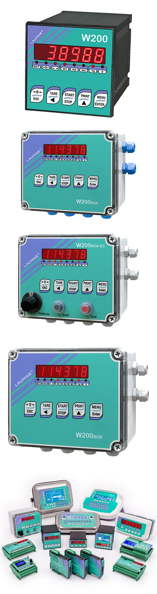
Indicator with 6-wire load cell input in DIN box (96x96x130 mm; drilling template 91×91 mm) for panel front mounting. Front panel protection rating IP54 (IP65 front optional). 6-digit semi−alphanumeric display, 14 mm, 7 segments; 8 indicator LEDs. 5−key membrane keypad with buzzer. Real-time clock/calendar with buffer battery.
W200BOX — IP67 waterproof ABS box version: dimensions 170x140x95 mm; four fixing holes
Ø 4 mm (centre distance 152×122 mm).
W200BOX-EC — IP64 waterproof ABS box version: dimensions 170x140x95 mm, four fixing holes
Ø 4 mm (centre distance 152×122 mm). Equipped with external selector switch for formula selection
(EC option), Start and Stop buttons.
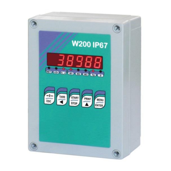
W200 IP67 — IP67 waterproof polycarbonate box version: dimensions 180x130x77 mm, four fixing holes Ø 4 mm (centre distance 163×113 mm).
W200 IP64 — IP64 waterproof polycarbonate box version: dimensions 180x130x77 mm, four fixing holes Ø 4 mm (centre distance 163×113 mm). Equipped with external selector switch for formula selection (EC option), Start and Stop buttons, four PG9 cable glands.
6 PRODUCTS version is supplied complete with a RELE6PROD 8-relay module (80x160x60 mm, available with 12/24 VDC or 115 VAC or 230 VAC power supply).
14 PRODUCTS version is supplied complete with a RELE6PROD 8-relay module (80x160x60 mm, available with 12/24 VDC or 115 VAC or 230 VAC power supply) and a RELE14PROD 8-relay module (80x120x60 mm).
Two serial ports (RS485 and RS232) for connection to: PC/PLC up to 32 instruments (max 99 with line repeaters) by ASCII Laumas or ModBus R.T.U. protocol, remote display, printer. Optional: integrated Profibus DP, DeviceNet, CANopen, Profinet IO, Ethernet/IP, Ethernet TCP/IP,
Modbus/TCP output.
BUFFER BATTERY
The instrument is equipped with an internal battery that allows to keep active the internal clock even in the event of power failure.
At the first start and after long periods of inactivity, leave the instrument on for at least 12 hours to fully charge the battery.
— 4 —
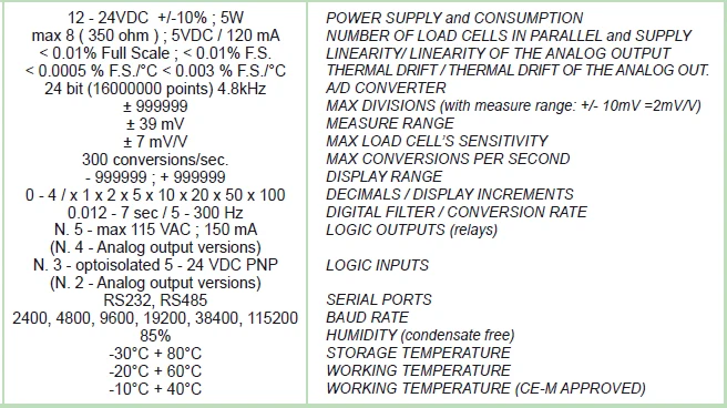
TECHNICAL SPECIFICATIONS
POWER SUPPLY and CONSUMPTION (VDC)
POWER SUPPLY and CONSUMPTION (VAC)
NO. OF LOAD CELLS IN PARALLEL and SUPPLY
12/24 VDC ±10%; 5 W (standard)
115/230 VAC (optional); 50-60 Hz; 6 VA max 8 (350 ohm); 5 VDC / 120 mA
LINEARITY / ANALOG OUTPUT LINEARITY < 0.01% F.S.; < 0.01% F.S.
THERMAL DRIFT / ANALOG OUTPUT THERMAL DRIFT < 0.0005% F.S./°C; < 0.003% F.S./°C
A/D CONVERTER
MAX DIVISIONS
(with measurement range ±10 mV = sens. 2 mV/V)
MEASUREMENT RANGE
MAX SENSITIVITY OF USABLE LOAD CELLS
MAX CONVERSIONS PER SECOND
24 bit (16000000 points)
±999999
±39 mV
±7 mV/V
300 conversions/second
DISPLAY RANGE
NO. OF DECIMALS / DISPLAY INCREMENTS
DIGITAL FILTER / READINGS PER SECOND
RELAY LOGIC OUTPUTS
±999999
0÷4 / x 1 x 2 x 5 x 10 x 20 x 50 x 100
0.012÷7 s / 5÷300 Hz
N.5 — max 115 VAC; 150 mA
(N. 4 – analog output version)
LOGIC INPUTS
SERIAL PORTS
BAUD RATE
HUMIDITY (non condensing)
STORAGE TEMPERATURE
WORKING TEMPERATURE
OPTOISOLATED ANALOG OUTPUT (OPTIONAL)
16 bit — 65535 divisions
RELE6PROD TECHNICAL SPECIFICATIONS
POWER SUPPLY and CONSUMPTION (VDC)
POWER SUPPLY and CONSUMPTION (VAC)
RELAY LOGIC OUTPUTS
HUMIDITY (non condensing)
STORAGE TEMPERATURE
WORKING TEMPERATURE
N.3 — optoisolated 5 — 24 VDC PNP
(N. 2 – analog output version)
RS485, RS232
2400, 4800, 9600, 19200, 38400, 115200
85%
-30°C +80°C
-20°C +60°C
0÷20 mA; 4÷20 mA (max 300 ohm);
0÷10 V; 0÷5 V; ±10 V; ±5 V (min 10 kohm)
12/24 VDC (standard) ±10%; 2 W
115/230 VAC (optional); 50-60 Hz; 1.5 VA
N.8 — max 115 VAC; 2 A
85%
-30°C +80°C
-20°C +60°C
— 5 —
ELECTRICAL CONNECTIONS
TERMINALS LEGEND
1
+SUPPLY (12/24 VDC)
115/230 VAC optional version:
+OUTPUT (24 VDC)
15 OUTPUT No. 5:
— SLOW/ALARM (3/14 PRODUCTS version)
— ALARM (6 PRODUCTS version)
otherwise:
+ANALOG OUTPUT (0÷10 V)
16 (12/24
RS232, RS485: SHIELD, GND
E/EC OPTION: GND
115/230 VAC optional version:
-OUTPUT (24 VDC)
RS232, RS485: SHIELD, GND
E/EC OPTION: GND
3 RS232: TXD
4 RS232: RXD
5 OUTPUT No. 1:
— PRODUCT 1 (3 PRODUCTS version)
— connect to RELE6PROD module
(6/14 PRODUCTS version)
6 OUTPUT No. 2:
— PRODUCT 2 (3 PRODUCTS version)
— connect to RELE6PROD module
(6/14 PRODUCTS version)
7 OUTPUT No. 3:
— PRODUCT 3 (3 PRODUCTS version)
— connect to RELE6PROD module
(6/14 PRODUCTS version)
8 OUTPUT No. 4:
— CYCLE END (3 PRODUCTS version)
— connect to RELE6PROD module
(6/14 PRODUCTS version)
9 OUTPUT COMMON
10 INPUT No. 1: START
(+VDC min 5 V max 24 V)
11 INPUT No. 2: STOP
(+VDC min 5 V max 24 V)
12 INPUT COMMON (-VDC 0 V)
13
14 INPUT No. 3: selectable
(+VDC min 5 V max 24 V)
otherwise:
+ANALOG OUTPUT (0÷20 o 4÷20 mA)
17 RS485: —
18 RS485: +
19
-LOAD CELL EXCITATION (-Exc)
LOAD CELL SHIELD
20
21
22
E/EC OPTION
otherwise:
-ANALOG OUTPUT COMMON
+LOAD CELL EXCITATION (+Exc)
+LOAD CELL REF/SENSE
-LOAD CELL REF/SENSE
23 -LOAD CELL SIGNAL (-Sig)
24
+LOAD CELL SIGNAL (+Sig)
N NEUTRAL (115/230 VAC optional version)
GROUND (115/230 VAC optional version)
— 6 —
“RELE6PROD” MODULE:
— from 9 to 20 terminals: control from 1 to 6
PRODUCTS
— 21-22 = CYCLE END
— from 1 to 16 terminals: control from 7 to 14
PRODUCTS
— 23-24 = SLOW (only for 6 PRODUCTS ver.)
BASIC INFORMATION
— It is recommended that the power supply negative pole be grounded.
— It is possible to supply up to eight 350 ohm load cells or sixteen 700 ohm load cells.
— For 4-wire load cells, make a jumper between EX- and REF- and between EX+ and REF+.
— Connect terminal “– SUPPLY” to the RS485 common of the connected instruments in the event that these receive alternating current input or that they have an optically isolated RS485.
— In case of an RS485 network with several devices it is recommended to activate the 120 ohm termination resistance on the two devices located at the ends of the network, as described in the paragraph RS485 SERIAL CONNECTION.
— Option E/EC: selects the first 12 formulas.
CHANGING VOLTAGE 115 VAC / 230 VAC
Remove the instrument power board and work on the welding side: join the red points using a stiff wire
230 Vac 115 Vac
115 115
230
115
230
115
— 7 —
12-24 Vdc supply
RS232
OUTPUTS max 115 Vac
150 mA
INPUTS supply
5-24 Vdc
W200 3 PRODUCTS
E OPTION
1 2 3 4 5 6 7 8 9 10 11 12 13 14 15 16
1 2 3 4 5 6
7 8
9 10 11 12
Buttons not included in the supply
EC OPTION
4
3
2
1
5
6 7
8
9
10
11
12
(1) ANALOG OUTPUT
OPTION
14 15 16
2
2
16
to instrument
16
13
14 15
16 17 18 19 20 21 22 23 24
*
4-WIRE load cell
CONNECTION
19 20 21 22 23 24
INPUT supply
5-24 Vdc
RS485
LOAD CELLS
6-WIRE load cell
CONNECTION
Current output: max load 300 ohm
Voltage output: min.load 10 kohm
WARNING! 115 V / 230 V OPTIONS
) The IN3 input can have the following functions:
— APPROVAL (default)
— SEMI-AUTOMATIC ZERO
— NET/GROSS WEIGHT
(1) If the analog output is present (ANALOG OUTPUT
OPTION) the following are no longer available:
— IN3 input
— SLOW/ALARM output
— E/EC options
L N
L N
INSTRUMENT
1 2 3
115/230
VAC
24 VDC
OUTPUT
WARNING: connect power supply specified on the plate found on the back of the instrument.
In 115 V and 230 V versions, terminals “+ SUPPLY” and “– SUPPLY” generate continuous voltage at 24 Vdc only to be used as power supply for instrument inputs.
— 8 —
W200 6 PRODUCTS
POWER
P1
RELAY
P2
RELAY
P3
RELAY
P4
RELAY
P5
RELAY
P6
RELAY
FC
RELAY
LE
RELAY
L N 3 4 5 6 7 8 9 10 11 12 13 14 15 16
17 18 19 20 21 22 23 24
MMON
ON
P
T
STO
STAR
IN COMM
OUT CO
TXD
RXD
R4
R3
R2
R1
— SUPPLY
+ SUPPLY
R5
T. +
T. —
CITA
CITA
EX
EX
REF./SENSE +
SIGNAL —
SIGNAL +
REF./SENSE —
IN 3
E — EC PT.
RM
to O
ALA
MMON CO to IN
mA
DC
20
V
4-
MON
+ 0-10
+ 0-20
— COM
T. +
T. —
—
+
AL
AL
SIGN
SIGN
EXCITA
EXCITA
— 9 —
+ SUPPLY OUT
— SUPPLY OUT
W200 14 PRODUCTS
POWER
P7
RELAY
P8
RELAY
P9
RELAY
P10
RELAY
P11
RELAY
P12
RELAY
P13
RELAY
P14
RELAY
1 2 3 4 5 6 7 8 9 10 11 12 13 14 15 16
POWER
P1
RELAY
P2
RELAY
P3
RELAY
P4
RELAY
P5
RELAY
P6
RELAY
FC
RELAY
LE
RELAY
L N 3 4 5 6 7 8 9 10 11 12 13 14 15 16 17 18 19 20 21 22 23 24
MMON
ON
P
T
STO
STAR
IN COMM
OUT CO
TXD
RXD
R4
R3
R2
R1
— SUPPLY
+ SUPPLY
R5
T. +
T. —
CITA
CITA
EX
EX
REF./SENSE +
SIGNAL —
SIGNAL +
REF./SENSE —
IN 3
E — EC PT.
to O
SLOW / ALARM
MMON CO to IN
AL —
AL +
SIGN
SIGN
CITAT. —
CITAT. + EX
EX
0 mA
ON
10 VDC
20 4-2
+ 0-
+ 0-
— COMM
— 10 —
+ SUPPLY OUT
— SUPPLY OUT
INTRODUCTION TO THE OPERATION
The batching programs for 3/6/14 products are used to realize a mixture of different products, which are loaded on a single weighing structure.
The instrument is able to load automatically a settable amount for each product, driving the relative batching organ (even two-speed) through the dedicated contact.
The instrument has the following features:
— Maximum 99 settable formulas (see section FORMULAS PROGRAMMING);
— Formulas programming in fixed or variable steps (see section FORMULAS PROGRAMMING);
— Batching resume after blackout (see section RESUME BATCHING AFTER A POWER CUT);
— Automatic fall calculation (see section FALL);
— Autotare at batching start (see section AUTOTARE);
— Tolerance error control (see section TOLERANCE);
— Precision batching through slow function (see section SLOW);
— Precision batching through tapping function (see section TAPPING FUNCTION);
— Consumption storage (see section CONSUMPTION);
— Print of batching data (see section PRINT AT CYCLE END);
— Alarm contact (see section ALARM RELAY CLOSURE);
BATCHING START:
— via keypad, setting formula and cycle number to be performed;
— via external contact (see section BATCHING START FROM EXTERNAL CONTACT).
For further information on the batching sequence, see section BATCHING.
FORMULAS PROGRAMMING IN STEPS:
The programming products order in formulas is, by default, fixed and ascending (FIXED STEPS); however it is still possible to program the products order, even repeating several times the same product (VARIABLE STEPS).
CONSUMPTION STORAGE:
The instrument, at the end of every batching, stores the consumed amount for each product.
Consumption value can be viewed directly on instrument display in standby mode.
INSTRUMENT CALIBRATION:
The instrument calibration can be performed both with THEORETICAL CALIBRATION, setting the instrument full scale and the load cells sensitivity (see section THEORETICAL CALIBRATION), and with REAL CALIBRATION through SAMPLE WEIGHT (see section REAL CALIBRATION (WITH
SAMPLE WEIGHTS)).
ALARM MANAGEMENT:
If an alarm occurs during the batching, the instrument shows the alarm on the display, closes the related contact (if enable) and waits for operator intervention to abort or continue the batching.
— 11 —
LED AND KEY FUNCTION
kg g
W1
W2
W3
LED Function
NET net weight (semi-automatic tare or preset tare)
0 zero (deviation from zero not more than ±0.25 divisions) stability unit of measure: kg unit of measure: g
Long press
(3 s)
Gross Net
Batching start / stop
Print menu
Setting formulas and batching constants
Setting general parameters
+
(press immediately followed by )
+ Setting preset tare (press immediately followed by )
Net Gross mV load cell test
Formula selection for START input
(EC not present)
Into menus
Select figure to be modified or go to previous menu item.
Modify selected figure or go to next menu item.
Confirm or enter in submenu
Into menus LEDs light up in sequence to indicate that it is not displaying a weight.
— 12 —
MENU MAP
Into menus changes are applied right after pressing the ENTER key (no further confirmation is required).
SYSTEM PARAMETERS
*: only for 3 and 14 products versions
— 13 —
BATCHING CONSTANTS
*: it appears only if in constants TOTAL = YES
— 14 —
INSTRUMENT COMMISSIONING
Upon switch-on, the display shows in sequence:
— → (ONLY in case of approved program);
— instrument model (e.g.: );
— followed by the software code (e.g.: );
— program type: (base); ; ; ; ; ; (no active program);
— followed by the software version (e.g.: );
— followed by the hardware code (e.g.: );
— serial number (e.g.: );
Check that the display shows the weight and that when loading the load cells there is an increase in weight. If there is not check and verify the connections and correct positioning of the load cells.
— If the instrument has already been theoretical CALIBRATED (plant system identification tag present on the instrument and on the cover: load cell’s rated data already entered):
▫ Reset to zero (see section TARE WEIGHT ZERO SETTING)
▫ Check the calibration with sample weights and correct the indicated weight if necessary (see section REAL CALIBRATION (WITH SAMPLE WEIGHTS)).
— If the instrument HAS NOT BEEN CALIBRATED (missing plant system identification tag) proceed with calibration:
▫ If load cells data are unknown, follow the procedure in section REAL CALIBRATION (WITH
SAMPLE WEIGHTS)
▫ Enter the rated data of load cells following the procedure given in section THEORETICAL
CALIBRATION
▫ Reset to zero (see section TARE WEIGHT ZERO SETTING)
▫ Check the calibration with sample weights and correct the indicated weight if necessary (see section REAL CALIBRATION (WITH SAMPLE WEIGHTS)).
— If you use the analog output, set the desired analog output type and the full scale value (see section ANALOG OUTPUT).
— If you use serial communication, set the related parameters (see section SERIAL
COMMUNICATION SETTING).
— Set instrument’s clock with current date and time (see section DATE AND TIME SETTING)
Required settings for the first batching:
— Access the Batching Constants menu and set the minimum weight value (see section MINIMUM
WEIGHT);
— Access the Formulas menu and set the formula 01 (see section FORMULAS PROGRAMMING);
— Start the batching by pressing the START button or by closing the START contact
— 15 —
PROGRAMMING OF SYSTEM PARAMETERS
From the weight display, press simultaneously keys MENU and ESC to access the parameter setting.
MENU/ENTER: to enter a menu/confirm the data entry.
▲: to modify the displayed figure or menu item.
◄: to select a new figure or modify the displayed menu item.
ESC: to cancel and return to the previous menu.
THEORETICAL CALIBRATION
This function allows the load cell rated values to be set.
To perform the theoretical calibration set the following parameters in sequence:
— (Default: ): The system full scale is given by one cell capacity multiplied by the number of cells used. Example: 4 cells of 1000 kg FULL SCALE = 1000 x 4 = 4000.
The instrument is supplied with a theoretical full scale value corresponding to 10000. To restore factory values, set 0 as full scale.
— (Default: 2.00000 mV/V): Sensitivity is a load cell rated parameter expressed in mV/V.
Set the average sensitivity value indicated on the load cells. It’s possible to set a value between
0.50000 and 7.00000 mV/V. Example of 4-cell system with sensitivity: 2.00100, 2.00150,
2.00200, 2.00250; enter 2.00175, calculated as (2.00100 + 2.00150 + 2.00200 + 2.00250) / 4.
—
: The division (resolution) is the minimum weight increment value which can be displayed. It is automatically calculated by the system according to the performed calibration, so that it is equal to 1/10000 of full scale. It can be changed and be variable between 0.0001 and
100 with x1 x2 x5 x10 increments.
— By modifying the theoretical full scale, the sensitivity or divisions, the real calibration is cancelled and the theoretical calibration only is considered valid.
— If the theoretical full scale and the recalculated full scale in real calibration (see section
REAL CALIBRATION (WITH SAMPLE WEIGHTS)) are equal, this means that the calibration currently in use is theoretical; if they are different, the calibration in use is the real calibration based on sample weights.
— By modifying the theoretical full scale, the sensitivity or divisions and all the system’s parameters containing a weight value will be set to default values.
— 16 —
TARE WEIGHT ZERO SETTING
This menu may also be accessed directly from the weight display, holding down the
0
key for 3 seconds.
Perform this procedure after having set the THEORETICAL CALIBRATION data.
Use this function to set to zero the weight of the empty system after commissioning and then later on to compensate zero variations due to the presence of product residues.
Procedure:
— Confirm the message (Zero) by pressing ENTER.
— The weight value to be set to zero is displayed. In this phase all of the LEDs are flashing.
— Confirming once again, the weight is set to zero (the value is stored to the permanent memory).
— Press ▲ to display the value of the total weight reset by the instrument, given by the sum of all of the previous zero settings.
ZERO VALUE MANUAL ENTRY
WARNING: Perform this procedure only if it’s not possible to reset the weighed structure tare, for example because it contains product that can not be unloaded.
Set in this parameter the estimated zero value (from 0 to max 999999; default: 0).
— 17 —
REAL CALIBRATION (WITH SAMPLE WEIGHTS)
After having performed the THEORETICAL CALIBRATION and TARE WEIGHT ZERO
SETTING, this function allows correct calibration to be done using sample weights of known value and, if necessary, any deviations of the indicated value from the correct value to be corrected.
Load onto the weighing system a sample weight, which must be at least 50% of the maximum quantity to be weighed.
By confirming the message the flashing value of the weight currently on the system is displayed. In this phase all of the LEDs are off. Adjust the value on display by using the arrow keys if necessary. After confirming, the new set weight will appear with all the LEDs flashing.
After an additional confirmation, the message will be restored and by repeatedly pressing the key ESC the weight will once again be displayed.
Example: for a system of maximum capacity 1000 kg and 1 kg division, two sample weights are available, one of 500 kg and the other one of 300 kg. Load both weights onto the system and correct the indicated weight to 800. Now remove the 300 kg weight, the system must show 500; remove the
500 kg weight, too; the system must read zero. If this does not happen, it means that there is a mechanical problem affecting the system linearity.
WARNING: identify and correct any mechanical problems before repeating the procedure.
— If theoretical full scale and recalculated full scale in real calibration are equal, it means that the theoretical calibration is currently in use; otherwise, the real calibration based on sample weights is in use.
— If the correction made changes the previous full scale for more than 20%, all the parameters with settable weight values are reset to default values.
LINEARISATION OPTION ON MAX 5 POINTS:
It is possible to perform a linearisation of the weight repeating the above-described procedure up to a maximum of five points, using five different sample weights. The
procedure ends by pressing the ESC button or after entering the fifth value; at this point it will no longer be possible to change the calibration value, but only to perform a new real calibration. To perform a new calibration, should return to the weight display and then re-entering into the calibration menu.
By pressing ▲ after having confirmed the sample weight that has been set, the full scale appears, recalculated according to the value of the maximum sample weight entered and making reference to the cell sensitivity set in the theoretical calibration ().
— 18 —
FILTER ON THE WEIGHT
Setting this parameter allows a stable weight display to be obtained.
To increase the effect (weight more stable) increase the value (from 0 to 9, default 4).
As seen in the diagram:
— By confirming the message, the currently programmed filter value is displayed.
— By changing and confirming the value, the weight is displayed and it will be possible to experimentally verify its stability.
— If stability is not satisfactory, confirming brings back the message and the filter may be modified again until an optimum result is achieved.
The filter enables to stabilise a weight as long as its variations are smaller than the corresponding
“response time”. It is necessary to set this filter according to the type of application and to the full scale value set.
FILTER VALUE
Response times
[ms]
Display and serial port refresh frequency
[Hz]
0 12
1 150
2 260
3 425
4 (default) 850
5 1700
6 2500
7 4000
8 6000
9 7000
300
100
50
25
12.5
12.5
12.5
10
10
5
ANTI PEAK
When the weight is stable, the anti peak filter removes any sudden disturbances with a maximum duration of 1 second. Confirm the filter on the weight with ENTER and select one of the following options:
— : anti peak filter enabled (default);
— : anti peak filter disabled.
— 19 —
ZERO PARAMETERS
RESETTABLE WEIGHT SETTING FOR SMALL WEIGHT CHANGES
(from 0 to max full scale; default: 300; considered decimals: 300 – 30.0 – 3.00 – 0.300): this parameter indicates the maximum weight value resettable by external contact, keypad or serial protocol.
AUTOMATIC ZERO SETTING AT POWER-ON
(from 0 to max 20% of full scale; default: 0): If at switch-on the weight value is lower than the value set in this parameter and does not exceed the value, the weight is reset. To disable this function, set 0.
ZERO TRACKING
(from 1 to 5, default: ): When the weight value is stable and, after a second, it deviates from zero by a figure in divisions smaller or equal to the figure in divisions set in this parameter, the weight is set to zero. To disable this function, set .
Example: if the parameter is set to 5 and is set to 2, the weight will be automatically set to zero for variations smaller than or equal to 10 ( x ).
— 20 —
SETTING UNITS OF MEASURE
These are the available units of measure:
: kilograms
: grams
: tons
: pounds
: newtons
: litres
: bars
: atmospheres
: pieces
: other generic units of measure not included in the list
If the print function is enabled, the symbol corresponding to the selected unit of measure will be printed after the measured value.
OUTPUTS AND INPUTS CONFIGURATION
OUTPUTS
3 PRODUCTS version:
— OUTPUTS 1-3: PRODUCTS 1-3.
— OUTPUT 4: CYCLE END.
6 — 14 PRODUCTS version:
— OUTPUTS 1-4: refer to relay modules decoding tables (see wiring diagrams and section TEST)
3 — 14 PRODUCTS version:
— OUTPUT 5 (Default = ): it’s possible to select one of the following functions:
— (ALARM): the relay is closed when an alarm is present.
— (SLOW): slow function for a precision batching.
6 PRODUCTS VERSION:
— OUTPUT 5: ALARM (the relay is closed when an alarm is present)
— 21 —
INPUTS
— INPUT 1: START
— INPUT 2: STOP
— INPUT 3 (Default = ): It’s possible to select one of the following functions:
— (NET/GROSS): by closing this input for no more than one second, it’s making an operation of SEMI-AUTOMATIC TARE and the display will show the net weight. To display the gross weight again, hold the NET/GROSS input closed for 3 seconds.
— (SEMI-AUTOMATIC ZERO): by closing the input for no more than one second, the weight is set to zero (see section SEMI-AUTOMATIC ZERO (WEIGHT ZERO-SETTING
FOR SMALL VARIATIONS)).
— (APPROVAL): the instrument starts the batching only after verifying that this input is closed.
SEMI-AUTOMATIC TARE (NET/GROSS)
THE SEMI-AUTOMATIC TARE OPERATION IS LOST UPON INSTRUMENT POWER-
OFF.
To perform a net operation (SEMI-AUTOMATIC TARE), close the NET/GROSS input or press the
TARE key for less than 3 seconds. The instrument displays the net weight (just set to zero) and the
NET LED lights up. To display the gross weight again, keep the NET/GROSS input closed or press
TARE for 3 seconds.
This operation can be repeated many times by the operator to allow the loading of several products.
Example:
Put the box on the scale, the display shows the box weight; press TARE, the display shows the net weight to zero; introduce the product in the box, the display shows the product weight. This operation can be repeated several times.
While the net weight is displayed, keep ▲ pressed to display gross weight. When
the key is released the net weight will be displayed again.
The semi-automatic tare operation is not allowed if the gross weight is zero.
— 22 —
PRESET TARE (SUBTRACTIVE TARE DEVICE)
It is possible to manually set a preset tare value to be subtracted from the display
value provided that the ≤ max weight condition is verified.
By default the instrument shows the last programmed preset tare value: to apply it press ▲ and then ENTER.
After setting the tare value, going back to the weight display, the display shows the net weight
(subtracting the preset tare value) and the NET LED lights up to show that a tare has been entered.
To delete a preset tare and return to gross weight display, hold down TARE for about 3 seconds or keep the NET/GROSS input (if any) closed for the same length of time (3 seconds). The preset tare value is set to zero. The NET LED is turned off when the gross weight is displayed once again.
While the net weight is displayed, keep ▲ pressed to display the gross weight. When the key is released the net weight will be displayed again.
— IF A SEMI-AUTOMATIC TARE (NET) IS ENTERED, IT IS NOT POSSIBLE TO
ACCESS THE ENTER PRESET TARE FUNCTION.
— IF A PRESET TARE IS ENTERED, IT’S STILL POSSIBLE TO ACCESS THE SEMI-
AUTOMATIC TARE (NET) FUNCTION. THE TWO DIFFERENT TYPES OF TARE ARE
ADDED.
ALL THE SEMI-AUTOMATIC TARE (NET) AND PRESET TARE FUNCTIONS WILL BE
LOST WHEN THE INSTRUMENT IS TURNED OFF.
SEMI-AUTOMATIC ZERO (WEIGHT ZERO-SETTING FOR SMALL VARIATIONS)
By closing the SEMI-AUTOMATIC ZERO input, the weight is set to zero; alternatively, by pressing the
0
key for less than 3 seconds, the message is displayed for 3 seconds, by pressing ENTER the weight is set to zero.
This function is only allowed if the weight is lower than the value (see section
RESETTABLE WEIGHT SETTING FOR SMALL WEIGHT CHANGES), otherwise the alarm
appears and the weight is not set to zero.
— 23 —
ANALOG OUTPUT(ONLY FOR INSTRUMENTS WHERE THIS OPTION IS AVAILABLE)
— : it selects the analog output type (4÷20 mA, 0÷20 mA, 0÷10 V, 0÷5 V, ±10 V, ±5 V; default: 4÷20 mA).
For the output ±10 V and ±5 V the soldered jumper SW1 must be closed:
▫ open the instrument, releasing with a screwdriver the locking tabs that hold together the two sides of the case;
▫ locate on the printed circuit board the soldered jumper SW1 highlighted in the picture below:
▫ close the jumper shorting the pads with a drop of tin.
— : choice of a weight followed by the analog output: gross () or net (). If the net function is not active, the analog output varies according to gross weight.
— : set the weight value for which you wish to obtain the minimum analog output value.
Only set a value different from zero if you wish to limit the analog output range; for instance: for a full scale value of 10000 kg you require an 4 mA signal at 5000 kg and
20 mA at 10000 kg, in this case, instead of zero, set 5000 kg.
— : set the weight value for which you wish to obtain the maximum analog output value; it must correspond to the value set in the PLC program (default: calibration full scale). E.g.: if I am using a 4÷20 mA output and in the PLC program I wish to have 20 mA = 8000 kg, I will set the parameter to 8000.
— : analog output correction to zero: if necessary adjust the analog output, allowing the PLC to indicate 0. The sign “-“ can be set for the last digit on the left. E.g.: if I use a 4÷20 mA output and, with the minimum analog setting, the PLC or tester read 4.1 mA, I must set the parameter to
3.9 to obtain 4.0 on the PLC or tester.
— : correction of analog output to full scale: if necessary permit modification of the analog output by allowing PLC to indicate the value set in the parameter . E.g. if I am using a
4÷20 mA output with the analog set to full scale and the PLC or tester reads 19.9 mA, I must set the parameter to 20.1 to get 20.0 on the PLC or tester.
— 24 —
Minimum and maximum values which can be set for zero and full scale corrections:
ANALOG OUTPUT TYPE Minimum Maximum
0÷10 V
0÷5 V
-0.150
-0.150
10.200
5.500
±10 V
±5 V
-10.300 10.200
-5.500 5.500
0÷20 mA
4÷20 mA
-0.200
-0.200
22.000
22.000
NOTE: the analog output may also be used in the opposite manner, i.e. the weight setting that corresponds to the analog zero () may be greater than the weight set for the analog full scale
(). The analog output will increase towards full scale as the weight decreases; the analog output will decrease as the weight increases.
For example:
= 10000 = 0 analog output 0÷10 V
Weight = 0 kg analog output = 10 V
Weight = 5000 kg analog output = 5 V
Weight =10000 kg analog output = 0 V
— 25 —
SERIAL COMMUNICATION SETTING
— / : communication port.
— : it disables any type of communication (default).
— : MODBUS-RTU protocol; possible addresses: from 1 to 99 (see Communication protocols manual).
— : continuous weight transmission protocol to RIP5/20/60, RIP50SHA, RIPLED series remote displays; the remote display shows the net weight or gross weight according to its settings (set: = , = , = ).
— : continuous weight transmission protocol to RIP675, RIP6125C series remote displays; the remote display shows the net weight or gross weight according to its settings
(set: = , = , = ).
— : continuous weight transmission protocol to RIP675, RIP6125C series remote displays (set: = , = , = ).
When the remote display is set to gross weight:
— if the instrument displays the gross weight, the remote display shows the gross weight.
— if the instrument shows the net weight, the remote display shows the net weight alternated with the message .
— : printer.
— : transmission speed (2400, 4800, 9600, 19200, 38400, 115200; default:
9600).
— : instrument address (da 1 a 99; default: 1).
— : delay in milliseconds which elapses before the instrument replies (from 0 to 200 ms; default: 0).
— :
— : no parity (default).
— : even parity.
— : odd parity.
— : stop bit (1 – 2; default: 1).
—
:
number of blank lines between one printout and the next
.
— : printing of custom heading from PC ( – ; default: ).
—
:
connected printer type:
—
—
—
For more information about protocols and methods of communication, request the proper manual to technical assistance.
— 26 —
W100
W200
WDOS
18 17 2
RS232 SERIAL COMMUNICATION
W100
W200
WDOS
3
4
2
2
3
5
DB9-F
PC
RS485 SERIAL COMMUNICATION
W100
W200
WDOS
18 17 2
W100
W200
WDOS
18 17 2
max 500 m
—
24 Vcc
+
VIN
0
TX
RX
CONVLAU
TX+
TX-
RX+
RX-
RS485 +
RS485 —
RS485 +
RS485 —
If the RS485 network exceeds 100 metres in length or baud-rate over 9600 are used, two terminating resistors are needed at the ends of the network. Two
120 ohm resistors must be connected between the “+” and “–” terminals of the
line, on the terminal strip of the furthest instruments. Should there be different
instruments or converters, refer to the specific manuals to determine whether it is
necessary to connect the above-mentioned resistors.
DIRECT CONNECTION BETWEEN RS485 AND RS232 WITHOUT CONVERTER
Since a two-wire RS485 output may be used directly on the RS-232 input of a PC or remote display, it is possible to implement instrument connection to an RS-232 port in the following manner:
INSTRUMENT
RS485 –
→
RS485 +
RS232
RXD
→ GND
This type of connection allows A SINGLE instrument to be used in a ONE WAY mode.
— 27 —
ALARM RELAY CLOSURE
The ALARM relay closing can be enabled or disabled for each of the following alarms: approval contact ();formula not programmed (); maximum weight exceeded (); minimum weight (); no increase in weight (); no decrease in weight (); tolerance (); fall
(); the PC did not read the batching data ().
: in presence of alarm, the relay is closed (default)
: the relay is not closed even in the presence of alarm
TEST
— Input Test:
: ensure that for each open input is displayed, is displayed when the input is closed.
— Output Test:
: setting ensure that the corresponding output opens. Setting ensure that the corresponding output closes.
Refer to the following tables to activate the relay of various products (only 6 and 14 products versions)
RELE6PROD MODULE RELE14PROD MODULE
R1 R2 R3 R4 OUTPUTS R1 R2 R3 R4 OUTPUTS
0 0 0 I PROD.7
0 I I 0 PROD.2
I 0 I 0 PROD.3
0 0 I 0 PROD.4
I I 0 0 PROD.5
0 I 0 0 PROD.6
I 0 0 I PROD.8
0 I 0 I PROD.9
I I 0 I PROD.10
0 0 I I PROD.11
I 0 I I PROD.12
X X X I SLOW I I I I PROD.14
— E/EC Option Test:
: It shows the formula selected by the E/EC option, if the option is not present or is not active, the message is displayed.
— Analog Output Option Test:
: It allows the analog signal to range between the minimum and the maximum values starting from the minimum.
: current output test.
: voltage output test.
— Millivolt Test:
: displays the load cell response signal in mV with four decimals.
— 28 —
DATE AND TIME SETTING
Selecting the item in the main menu, access is obtained to the date and time display menu.
Pressing ENTER several times scrolls through days — months – years and hours – minutes; pressing
◄ selects the figure to modify; pressing ▲ the figure increases; pressing ENTER you can confirm and go to the next menu item.
OPERATION SETTINGS
: maximum number of products and steps selectable in formula (example: if the version in use is the 6 products and the parameter is set to «4», you can set the products from 1 to 4 and at most 4 steps for each formula).
By changing the value, all formulas are deleted.
It is possible to set:
— from 1 to 3 for 3 products version
— from 1 to 6 for 6 products version
— from 1 to 14 for 14 products version
(Default: ): formulas setting in variable or fixed steps.
By changing the value, all formulas are deleted.
— : products and quantities can be set in formulas in the desired order, even repeating several times the same product (VARIABLE STEPS).
— : products batching sequence is not adjustable, only quantities can be set (FIXED STEPS).
: Select the switch conditions from the opening of the batched product to the following or to the CYCLE END closing.
— (Default: ): time set in constants ().
— (Default: ): START input closure or ENTER key pressure.
— (Default: ): stable weight.
(Default: ): Select the batching resume mode after a power failure.
— : (Automatic) at the power restore, appears for 3 seconds, after which the batching resumes from the point of interruption.
— : (Manual) at the power restore appears, press ENTER to resume the batching or press ESC to stop it.
— 29 —
INFO MENU
: active options are displayed.
PROGRAMMING OF BATCHING CONSTANTS
From weight display press MENU, then press ▲ several times until is displayed and confirm.
MENU/ENTER: to enter a menu/confirm the data entry.
▲: to modify the displayed figure or menu item.
◄: to select a new figure or modify the displayed menu item.
ESC: to cancel and return to the previous menu.
MINIMUM WEIGHT
(from 0 to max full scale; default: 10): minimum weight, value at which the scale is considered empty. Batching start is only allowed if the weight is lower than this value, during the unloading phase the CYCLE END contact will be opened when the weight reaches this value and after the safe emptying time is over.
MAXIMUM WEIGHT
(from 0 to max full scale; default: 0): settable and displayable maximum weight. If the displayed weight exceeds the maximum weight by 9 divisions, the message is displayed; if in the formulas programming the weight value set is greater than this value, the message is displayed and the value will not be stored.
By setting 0, the function is disabled.
SAFE EMPTYING TIME
(from 0.0 to max 999.9 seconds; default 5.0): time that is necessary for a perfect emptying of the scale. The instrument waits for this time during the unloading phase (CYCLE END closed), after reaching the minimum weight and before opening the CYCLE END contact to obtain a perfect emptying of the scale.
— 30 —
WAITING TIME
(from 0.0 to max 999.9 seconds; default 5.0): time between the end batching of one product and the following one.
NO PRODUCT LOAD TIME
(from 0.0 to max 999.9 seconds; default: 0.0): this parameter allows the product control during batching. if there is no product load, the instrument waits for a set duration of time before activating the alarm .
NO PRODUCT UNLOAD TIME
(from 0.0 to max 999.9 seconds; default: 0.0): this parameter allows the product control during the unloading phase (cycle end). If there is no product extraction, the instrument waits for a set duration of time before activating the alarm .
WARNING: The control is only actuated after unloading of the product has started (the weight must decrease by at least 10 divisions).
FALL
By FALL it means the correction of the product amount in fall after the batching STOP. This amount is in addition to the product already batched causing inaccuracy. The instrument is able to anticipate the batching STOP, to reduce this uncertainty, with two possible ways:
— AUTOMATIC fall: the instrument automatically calculates the fall;
— MANUAL fall: the instrument applies the fall set by the operator;
WARNING: Setting a value of WAITING TIME () such that the weight is stable at the end of the batching, otherwise the update of the AUTOMATIC fall is not correct.
(from 0 to 1; default: 0): it’s possible to select the automatic or the manual fall.
— = 0: MANUAL fall
— = 1: AUTOMATIC fall
(from 0 to maximum weight; default: 0): in this parameter it is possible to set the fall value for each product (only if = 0) or to display and/or to modify the fall value calculated automatically by the instrument (only if = 1).
— 31 —
TOLERANCE
(from 0 to maximum weight; default: 0): Adjustable parameter for each product that defines how much the batched weight value can deviate from the one set in formula. If the batched weight is higher or lower than the amount to be batched, for a value greater than the tolerance, the instrument closes the ALARM contact. Press ENTER to continue the batching. Example: if a PRODUCT = 1000 value is set and a TOLERANCE = 100 value is set, the batched weight must not be lower than 900 or higher than 1100 to allow the instrument to continue the batching process. By setting 0, the function is disabled.
SLOW
(from 0 to maximum weight; default: 0): adjustable parameter for each product. By slow value we mean the value that, when subtracted from the weight set, minus the fall value, starts the batching slow phase (closing the relative contact). If the value set is higher than the weight to be batched, batching will be all in slow phase. Setting 0 disables this function.
Esempio: If PRODUCT = 100, SLOW = 15 and FALL = 10, the slow phase starts when the weight reaches 75.
TAPPING FUNCTION
In the event that the batching instrument is not equipped with the speed “slow” it is possible to use this function to slow down the product batching in the final phase (through opening and closing cycles of the PRODUCT contact) and to increase the accuracy. Set in parameter the product amount you want to batch with the tapping function enabled.
SLOW ON
(from 0 to max 9.9; default: 0): time in which the PRODUCT relay remains closed during the SLOW phase. By setting 0, the function is disabled.
SLOW OFF
(from 0 to max 9.9; default: 0): time in which the PRODUCT relay remains open during the
SLOW phase. By setting 0, the function is disabled.
AUTOTARE
(from 0 to 1; default: 1): autotare enabling (automatic tare at the batching start).
— : autotare disabled
— : autotare enabled
This operation is possible only if the gross weight is lower than the minimum weight (), otherwise the alarm message is displayed.
— 32 —
CONSUMPTION FOR EACH PRODUCT
(default ): enabling consumption memory (total batched quantity) for each product.
— : consumption enabled;
— : consumption disabled.
PRINT AT CYCLE END
(Default ): function enabling to print batching data at cycle end.
— : print enabled
— : print disabled
CHECKING PC PRESENCE
(Default: ): check for a PC connected to the instrument.
— : PC presence check active; the instrument checks for a PC every 10 seconds. If no PC presence is detected, the instrument will display an alarm signal alternated with the weight value.
— : PC presence check not active.
WARNING: The check is active only if selected the Modbus protocol.
WAITING CONFIRMATION FROM PC (SLAVE)
(Default: ): waiting for confirmation of record batching data from PC.
— : check enabled; the instrument waits for the PC to read the batching data, before starting another batching. In case of recording failure, the instrument displays an alarm .
— : check disabled; at cycle end, the instrument will not wait for data recording on PC before performing another batching.
SWITCHING OF THE ALARM/SLOW RELAY ON WEIGHT
(from 0 to max full scale; Default: 0): by setting a value different from zero, the
ALARM/SLOW contact does not switch over in case of alarm/slow, but behaves as a SETPOINT contact; the relay closes when the weight reaches the value set in this parameter.
— 33 —
FORMULAS PROGRAMMING
Select the formula that you wish to program. It is possible to set max 99 formulas.
FIXED STEPS ( = , see section OPERATION SETTINGS):
It is only possible to set the quantity of product that you wish to batch, products batching sequence is not adjustable.
VARIABLE STEPS ( = , see section OPERATION SETTINGS):
It is possible to set the step number, the product number and the quantity of product that you wish to batch.
Example: (: step number; : product number).
An attempt to set a quantity higher than the maximum weight () set in the batching constants, the message is displayed.
DELETING FORMULAS
Confirm with ENTER the prompt, to delete one formula enter the formula number, to delete all formulas enter 00 (), confirm with ENTER, you will be prompted to confirm (), to delete confirm again with ENTER otherwise press ESC to cancel the command.
— 34 —
BATCHING
Note: In case of alarm, the batching may be canceled by pressing the ESC button or by closing the
STOP input.
After having selected the formula and set the desired number of batching cycles, the first batching cycle starts as follows:
1. The instrument will ensure that:
— the formula has been programmed, otherwise it will display the alarm .
— the amount set in the formula does not exceed the set maximum weight (), otherwise the message is displayed.
— the input IN3 (if it is set as Approval) is closed, otherwise the message will be displayed; close the input IN3 to start the batching.
— Only if is set: the gross weight is lower than the minimum weight (), otherwise the alarm is displayed (it is always possible to force the batching start by pressing the
ENTER key).
— Only if = :
— If the consumed amount exceeds 999000, the message appears for a second.
—
If the consumed amount exceeds 999999, it is automatically set to zero.
2. Once the above listed conditions are met, the batching of first product programmed in formula is started; if the time is set and the product is not loaded for at least 20 divisions during this time interval, the relative alarm is displayed.
3. The number of the product to be batched (e.g. ) is displayed for 1 second and then the net weight; the product relay closes;
4. Only if is set: once the value set for that product has been reached, minus the fall and slow values, the SLOW contact closes (if foreseen); if tapping values have been set, the product contact carries out opening and closing cycles according to and times;
5. Once the value set for that product has been reached, minus any fall value, the product contact is opened interrupting product flow;
6. After the contact opening, the system shows the weight preceded by the letter and waits:
— Only if = : The waiting time has elapsed ().
— Only if = : The START input has been closed or the ENTER key has been pressed.
— Only if = : The weight is stable.
7. If the tolerance () is set and the batched quantity is lower than the set quantity minus this value, is made only one attempt of finishing re-start, in order to improve the batching precision.
In such a case, the PRODUCT contact is closed and returns to step 5, otherwise the alarm appears. If instead, the batched quantity is greater than the set amount plus this value, the alarm appears. Press ENTER to cancel the alarm and go on with the batching.
8. Only if = : consumption of the product just batched is stored;
9. If another product to be batched has been set in the formula, the instrument starts batching the new product and you return to point 3;
10. If there are no more products to be batched in the formula, the system enters the cycle end phase:
— 35 —
— The CYCLE END contact is closed;
— The display shows the weight preceded by the letter ;
— If printing is enabled: batching data are printed.
11. At the beginning of the product extraction, if the time is set and the product is not extracted by at least 20 divisions within this interval of time, the alarm message will be displayed.
12. The system ends the batching (opening of the CYCLE END contact) only after verifying that:
— The weight is lower than the minimum weight ();
— The safe emptying time has elapsed ();
13. Only if = : the instrument waits for data recording on PC, before being available for a new batching.
If several batching cycles have been set the instrument starts a new cycle.
BATCHING START FROM EXTERNAL CONTACT
It is possible to select the required formula via an external selector switch. After selecting the formula, close the START external contact for at least 0.5 seconds and, verified the conditions indicated in section BATCHING, the instrument will perform the selected formula batching.
If there is no the formula selection switch (E/EC options), the latest formula entered via the keypad will be batched, or it’s possible to set the required formula in the following menu: press the MENU key for 3 seconds, will be displayed, set the required formula number using the arrow keys and confirm with ENTER. At batching start, the set formula will be performed. If 00 is set, the latest formula set via keypad will be recalled.
If at the end of the batching, the START contact is closed, the same batching sequence is repeated.
— 36 —
BATCHING START FOR SINGLE PRODUCT WITH AUTOMATIC STOP
This function allows to batch a single product without having to set a special formula.
From weight displaying press START and select the formula; select the product to batch
(eg.: ) and set its amount; confirm with ENTER to perform the batching of the selected product.
The instrument updates the consumptions, production and stock values (if present and enabled) and sends the data to the printer (if enabled).
BATCHING START FOR SINGLE PRODUCT WITH STOP BY KEYBOARD
This function allows to batch a single product, leaving the operator the task to stop the batching.
From weight displaying press START and select the formula; select the product to batch
(eg.: ) and set its amount to 0; confirm with ENTER to close the relay of the selected product and start the batching; press STOP to stop it.
The instrument updates the consumptions, production and stock values (if present and enabled) and sends the data to the printer (if enabled).
UNLOADING START WITH AUTOMATIC STOP
This function allows to unload all the scale contents until it reaches the minimum weight.
From weight displaying press START, select the formula and select the product; confirm with ENTER to close the CYCLE END relay and start the scale unloading phase; this ends after reaching the minimum weight and after the safe emptying time has elapsed.
— 37 —
DISPLAYING DURING BATCHING
During the batching the display shows the net weight preceded by the letter .
By pressing ◄ the product number is displayed.
By pressing ▲ the formula number is displayed, by pressing it again the number of running cycle is displayed.
BATCHING STOP
— Open the START contact and close the STOP contact to stop the batching. If the START contact is closed, the alarm is displayed.
— To pause the batching at any time, press STOP, the prompt is displayed. Press ENTER to resume the batching or press again STOP to cancel it completely.
RESUME BATCHING AFTER A POWER CUT
If a blackout occurs during the batching (unloading phase included), when power comes back
appears: press ENTER to resume batching from the point of interruption, press ESC to cancel the batching and return to the weight displaying.
If in constants = , when power comes back appears and after 3 seconds the batching is automatically resumed.
Power failures do not cause any deletion of cycles still to be performed.
— 38 —
CONSUMPTION
If in constants consumption is enabled ( = ), the quantities batched for each product are stored.
Selecting the following information is displayed:
— total quantity consumed for all products (divided by 100);
— deletion data;
— quantity consumed for each product with no decimals.
The quantities will be printed out in full (with decimals).
CONSUMPTION DELETION
To delete consumption confirm , the deletion confirmation is requested; confirm again with ENTER or press ESC to cancel the command.
If the printer is enabled (see section SERIAL COMMUNICATION SETTING) an operation receipt is printed.
— 39 —
ALARMS
: (only = 1) it is displayed if, at batching start, the weight on the scale is higher than the minimum set in constants (). Press ESC to return to the weight displaying, press ENTER to cancel the alarm and continue with the batching. If the weight comes back below to the minimum set, the batching starts.
: it is displayed when at the batching start the APPROVAL input is open (if the input 3 is set as approval; In 3 = ). Close the input to enable batching or cancel it by pressing
ESC.
: it is displayed if at batching end the weight is different from the value set in formula by a value higher than tolerance. Press ENTER to cancel the alarm and continue with the batching.
: it is displayed if at batching start the fall value is higher than the product quantity to be batched. Press ESC to cancel the alarm and the batching.
: it is displayed if, at batching start, the formula recalled for running is not programmed.
Press the key ESC to quit.
: it is displayed if, at batching start, the formula recalled for running exceeds the maximum weight. Press the key ESC to quit.
: it means that during batching the STOP key has been pressed, temporarily interrupting the cycle; press the ENTER key to start it again, or STOP to terminate completely the batching.
: it indicates that a power failure occurred during batching: press ESC to cancel the batching or press ENTER to resume batching again from the point of interruption.
: during the batching it indicates that the product is not loaded. It is automatically cancelled if the product increases. Press STOP twice to cancel the batching.
: during the unload (Cycle End contact closed) it indicates that the product is not extracted.
It is automatically cancelled if the product decreases. Press STOP twice to cancel the unload.
: it is displayed for 3 seconds if you try to stop the batching (by pressing twice STOP or closing the related input) when the START input is closed. Open the START input to cancel the alarm.
: batching is cancelled. Press ESC to quit. If the alarm persists, contact technical assistance.
: it is displayed when there is a weight alarm and it cancels the current batching. Press
ESC to go back to the weight display and check the alarm.
: the load cell is not connected or is incorrectly connected; the load cell signal exceeds
39 mV; the conversion electronics (AD converter) is malfunctioning; the load cell is a
4−wire and there are no jumpers between EX- and REF- and between EX+ and REF+.
: the weight display exceeds 110% of the full scale.
: internal instrument converter failure; check load cell connections, if necessary contact technical assistance.
: the weight exceeds the maximum weight by 9 divisions.
: maximum displayable value exceeded (value higher than 999999 or lower than -999999).
: weight too high: zero setting not possible.
— 40 —
: this message appears in the sample weight setting, in real calibration, after the fifth sample weight value has been entered.
: the value set for the parameter is beyond the permitted values; press ESC to quit the setting mode leaving the previous value unchanged. Examples: a number of decimals is selected for full scale which exceeds the instrument’s display potential; value above the maximum setting value; the weight value set in sample weight verification does not match the detected mV increase; the analog output correction goes beyond the permitted limits.
: lock active on menu item, keypad or display.
: It’s not possible to display properly the number because is greater than 999999 or less than -999999.
: buffer battery low, loss of date and time of Real-Time Clock. Confirm with ENTER to continue; leave the instrument on for at least 12 hours to charge the battery, if the alarm persists contact technical assistance.
: an incorrect date has been detected: go into the related menu to check and correct it.
: waiting for START closure or ENTER key pressure to continue the batching.
:
MODE
Bit LSB
PC is not connected.
: PC has not read batching data.
Serial protocol alarms:
Status
Register
MODBUS RTU
76543210
xxxxxxx1
76543210
xxxx1xxx
76543210
xxxxxx1x
76543210
xxxxx1xx
76543210
On gross:
xxx1xxxx
On net:
xx1xxxxx
The instrument’s response to the zero command is a ‘value not valid’ error (error code 3)
RIP *
HDRIP-N
__O-F_ __O-L_ __O-F_
_ERCEL _ER_OL _ER_AD
__O-L_
######
__O-F_ __O-F_
_ER_OF O__SET
* For RIP remote displays, if the message exceeds 5 digits the display reads .
With an alarm the relays open and the analog outputs go to the lowest possible value according to the following table:
RANGE
Output value
0÷20 mA
-0.2 mA
4÷20 mA
3.5 mA
0÷5 V
-0.5 V
0÷10 V
-0.5 V
±10 V
0 V
±5 V
0 V
— 41 —
PRINTING EXAMPLES
If the printer has been set (see section SERIAL COMMUNICATION SETTING), from the weight display press the PRINT key for less than 3 seconds:
— : prints the displayed weight;
— : prints the constants (minimum weight, maximum weight, etc.);
— : prints one or all of the formulas; press ENTER to display , set the formula number to be printed or “00” to print them all;
— : prints consumption (only if = , see CONSUMPTION FOR EACH PRODUCT).
BATCHING PRINTOUT CONSTANTS PRINTOUT
————————
Batching in gross weight ( = 0)
W200 14PROD Addr:01
DATE: 01/10/11 08:30:01
————————
CONSTANTS
W200 14PROD Addr:01
MIN 10
FORMULA: 01
MASS 0
CYCLE: 1/ 1
TIME SIC 5.0
DATE: 01/10/11 08:30:01
TIME WAIT 5.0
TIME NLOAD 0.0
INIT.WEIGHT 10 kg
TIME NUNLOAD 0.0
P01 G 301: 300 kg
FALL MANUAL
P02 N 714: 700 kg
TIME SLOWON 0.0
P05 N 1025: 1000 kg
TIME SLOWOF 0.0
TOT G 2040: 2000 kg
AUTOTARE YES
TOTAL NO
Batching in net weight ( = 1)
PRINT NO
————————
PC NO
W200 14PROD Addr:01
FORMULA: 01
SLAVE NO
BLACKOUT MANUAL
CYCLE: 1/ 1
DATE: 01/10/11 08:30:01
PR FALL TOLER SLOW
02 0 0 200
TARE 10 kg
P01 N 301: 300 kg
P02 N 714: 700 kg
P05 N 1025: 1000 kg
TOT G 2050: 2000 kg
03 52 0 0
06 0 100 0
FORMULA PRINTOUT
————————
W200 14PROD Addr:01
DATE: 01/10/11 08:30:01
FORMULA: 01
P01 300 kg
P04 400 kg
P07 1000 kg
P11 400 kg
— 42 —
CONSUMPTION PRINTOUT
————————
W200 14PROD Addr:01
DATE: 01/10/11 08:30:52
CONSUMPTION
P01 2596 kg
P03 1066 kg
P04 487 kg
TOTAL 4149 kg
FROM: 01/09/11 09:16:45
If consumption is set to zero, it will also be printed:
CONSUMPTION ERASED
WEIGHT PRINTOUT
————————
W200 14PROD Addr:01
DATE: 12/09/11 14:48:12
GROSS 1204 kg
NET 831 kg
TARE 373 kg
— 43 —
RESERVED FOR THE INSTALLER
MENU LOCKING
Through this procedure, it’s possible to block the access to any menu on the instrument.
Select the menu that you wish to lock:
press ESC and ◄ simultaneously for 3 seconds, the display shows
(the left point on the text indicates that this menu item is now locked). If the operator tries to enter this menu, the access is denied and the display shows
MENU UNLOCKING
.
press ENTER and ▲ simultaneously for 3 seconds, the display shows
(the left point on the text is off to indicate that this menu item is unlocked).
TEMPORARY MENU UNLOCKING
press ▲ and ◄ simultaneously for 3 seconds: it is now possible to enter and modify all menus including those which are locked. By returning to weight display, the menu lock is restored.
DATA DELETION AND PROGRAM SELECTION
WARNING: operations must only be performed after contacting technical assistance.
After each operation the display shows , press ENTER to continue.
By pressing ESC the procedure is cancelled and no changes are made.
Upon instrument power-on hold down the ESC key until the display shows , then proceed as follows:
CONSTANTS RESTORE (does not erase the calibration): confirm , use arrow keys to select
, set code 6935 and confirm.
— 44 —
PROGRAM SELECTION: confirm and use the arrow keys to select the desired program:
: basic program, setpoint management only.
: to be used when the loaded weighing system correspond to not loaded cells and vice versa
(product increases while weight on load cells actually decreases).
: weight remote display program with setpoint.
: monoproduct loading program.
: monoproduct unloading program.
: 3 products batching.
: 6 products batching.
: 14 product batching.
: no program.
After confirming the choice of the program (except and ), the user must choose its approval state among the following possible choices:
: not approved program;
: approved program, single division (Dir. 2009/23/EC, art. 1)*;
: approved program, multi-interval (Dir. 2009/23/EC, art. 1)*;
: approved program, multiple range (Dir. 2009/23/EC, art. 1)*;
*) Contact technical assistance to request the proper manual and the correct procedures for approval, indicating mandatory hardware code and serial number (see section
INSTRUMENT COMMISSIONING).
By confirming, the instrument is restored to default and data is erased.
If you do not have a specific manual for the newly set program, you can request it
to technical assistance.
KEYPAD OR DISPLAY LOCKING
Press ESC immediately followed by ▲ hold them down for about 5 seconds (this operation is also possible via the MODBUS and ASCII protocols):
— : no lock.
— : keypad lock: if active, when a key is pressed the message is displayed for 3 seconds.
— : keypad and display lock: if active, the kaypad is locked and the display shows the instrument model (weight is not displayed); by pressing a key the display shows for 3 seconds.
—
— 45 —
DECLARATION OF CONFORMITY
SISTEMI DI PESATURA INDUSTRIALE — CELLE DI CARICO
Sistema di gestione
Qualità certificato
UNI EN ISO 9001:2008
LAUMAS Elettronica S.r.l.
CERTIFICAZIONE DEL SISTEMA DI GARANZIA DELLA QUALITÀ DELLA PRODUZIONE
email: [email protected] web: http://www.laumas.com
Tel. (+39) 0521 683124 — Fax (+39) 0521 681091
Via 1° Maggio 6 – 43022 Montechiarugolo (PR) Italy
C.F. — P.IVA IT01661140341
Fabbricante metrico Prot. N. 7340 Parma — R.E.A. PR N. 169833 — Reg. Imprese
PR N.19393 — Registro Nazionale Pile N° IT09060P00000982 — Registro A.E.E.
N° IT08020000002494 — N. Mecc. PR 008385 — Cap. Soc. Euro 10.400 int. vers.
EC-Konformitätserklärung
EC- Declaração de conformidade
EC-Deklaracja zgodno ści
EC-Declaration of Conformity
EC- Déclaration de conformité Conformidad
EC-Dichiarazione di conformità EC-Conformiteitverklaring
EC- Prohlášení o shode
EC-
Заявление о соответствии
I
Dichiarazione di conformità
Dichiariamo che il prodotto al quale la presente dichiarazione si riferisce è conforme alle norme di seguito citate.
GB
Declaration of conformity
We hereby declare that the product to which this declaration refers conforms with the following standards.
E
Declaración de conformidad
Manifestamos en la presente que el producto al que se refiere esta declaración está de acuerdo con las siguientes normas
D Konformitäts-erklärung
Wir erklären hiermit, dass das Produkt, auf das sich diese Erklärung bezieht, mit den nachstehenden
Normen übereinstimmt.
F
CZ
Déclaration de conformité
Prohlášení o shode
Nous déclarons avec cela responsabilité que le produit, auquel se rapporte la présente déclaration, est conforme aux normes citées ci-après.
Tímto prohlašujeme, že výrobek, kterého se toto prohlášení týká, je v souladu s níže uvedenými normami.
NL Conformiteit-verklaring
Wij verklaren hiermede dat het product, waarop deze verklaring betrekking heeft, met de hierna vermelde normen overeenstemt.
P
Declaração de conformidade
(only if “M” mark is applied)
Declaramos por meio da presente que o produto no qual se refere esta declaração, corresponde às normas seguintes.
PL Deklaracja ści
Niniejszym o świadczamy, że produkt, którego niniejsze oświadczenie dotyczy, jest zgodny z poni ższymi normami.
RUS
Заявление о соответствии
Мы заявляем, что продукт, к которому относится данная декларация, соответствует перечисленным ниже нормам.
Models: W200, W200IP64, W200IP67, W200BOX
Mark Applied EU Directive Standards
2006/95/EC
Low Voltage Directive
2004/108/EC
EMC Directive
Not Applicable (N/A) for VDC type
EN 61010-1 (2010) for 230/115 VAC type
EN 55022
EN 61000-6-2 (2002)
EN 61000-6-4 (2001)
EN 61000-4-2/3/6/8
2009/23/EC
NAWI Directive
EN 45501
OIML R-76-1 (2006)
LAUMAS Elettronica s.r.l.
M. Consonni (RCQ) Montechiarugolo (PR), 22/11/2013
— 46 —