![]()
MC1000 Series
Installation and Operation Manual
Phone: 800.894.0412 — Fax: 208.368.0415 — Web: www.ctiautomation.net — Email: info@ctiautomation.net

NOTE!
The manual covers software version M108314 and above.
See paramter 63 for the software version of the drive you are working with.
If you are working with an earlier software releaas, you will not have all of the functionality described in this manual, but the functionlity of the drive is fully documented in this manual.
If you are working with M108313 or ealier, parameters 69 and 70 are described in this manual as parameters 98 and 99.
Phone: 800.894.0412 — Fax: 208.368.0415 — Web: www.ctiautomation.net — Email: info@ctiautomation.net
1.0GENERAL
1.1PRODUCTS COVERED IN THIS MANUAL
This manual covers the AC Tech MC1000 Series Variable Frequency Drive.
1.2PRODUCT CHANGES
AC Technology Corporation reserves the right to discontinue or make modifications to the design of its products and manuals without prior notice, and holds no obligation to make modifications to products sold previously. AC Technology Corporation also holds no liability for losses of any kind which may result from this action. Instruction manuals with the most up-to-date information are available for download from the AC Tech web site. (www.actech.com).
1.3WARRANTY
AC Technology Corporation warrants the MC Series AC motor control to be free of defects in material and workmanship for a period of 24 months from the date of shipment from AC Tech’s factory. An MC Series control, or any component contained therein, which under normal use, becomes defective within the stated warranty time period, shall be returned to AC Technology Corporation, freight prepaid, for examination (contact AC Technology Corporation for authorization prior to returning any product). AC Technology Corporation reserves the right to make the final determination as to the validity of a warranty claim, and sole obligation is to repair or replace only components which have been rendered defective due to faulty material or workmanship. No warranty claim will be accepted for components which have been damaged due to mishandling, improper installation, unauthorized repair and/or alteration of the product, operation in excess of design specifications or other misuse, or improper maintenance. AC Technology Corporation makes no warranty that its products are compatible with any other equipment, or to any specific application, to which they may be applied and shall not be held liable for any other consequential damage or injury arising from the use of its products.
This warranty is in lieu of all other warranties, expressed or implied. Nootherperson,firmorcorporationisauthorizedtoassume,forACTechnology Corporation, any other liability in connection with the demonstration or sale of its products.
1.4RECEIVING
Inspect all cartons for damage which may have occurred during shipping. Carefully unpack equipment and inspect thoroughly for damage or shortage. Report any damage to carrier and/or shortages to supplier. All major components and connections should be examined for damage and tightness, with special attention given to PC boards, plugs, knobs and switches.
1.5CUSTOMER MODIFICATION
AC Technology Corporation, its sales representatives and distributors, welcome the opportunity to assist our customers in applying our products. Many customizing options are available to aid in this function. AC Technology Corporation cannot assume responsibility for any modifications not authorized by its engineering department.
Phone: 800.894.0412 — Fax: 208.368.0415 — Web: www1.ctiautomation.net — Email: info@ctiautomation.net
2.0MC1000 SPECIFICATIONS
|
Storage Temperature |
-20° to 70° C |
|
|
Ambient Operating Temperature |
Chassis (w/o cover) |
-10° to 55° C |
|
(With 2.5, 6, and 8 kHz carrier, |
Type 1 (IP 31) |
-10° to 50° C |
|
derate for higher carriers) |
Type 4 (IP 65) |
-10° to 40° C |
|
Type 12 (IP 54) |
-10° to 40° C |
|
|
Ambient Humidity |
Less than 95% (non-condensing) |
|
|
Altitude |
3300 feet (1000 m) above sea level |
|
|
without derating |
||
|
Input Line Voltages |
240/120 Vac, 240/200 Vac, |
|
|
480/400 Vac, and 590/480 Vac |
||
|
Input Voltage Tolerance |
+10%, -15% |
|
|
Input Frequency Tolerance |
48 to 62 Hz |
|
|
Output Wave Form |
Sine Coded PWM |
|
|
Output Frequency |
0-120 Hz, Optional up to 1000 Hz |
|
|
Carrier Frequency |
2.5 kHz to 14 kHz |
|
|
Frequency Stability |
+0.00006% / °C |
|
|
Service Factor |
1.00 |
|
|
Efficiency |
> 97% throughout speed range |
|
|
Power Factor (displacement) |
> 0.96 |
|
|
Overload Current Capacity |
150% of output rating for 60 seconds |
|
|
180% of output rating for 30 seconds |
||
|
Speed Reference Follower |
0-10 VDC, 4-20 mA |
|
|
Control Voltage |
15 VDC |
|
|
Analog Outputs |
0 — 10 VDC, or 2 — 10 VDC |
|
|
Proportional to speed and load |
||
|
Digital Outputs |
Form C relay: 2 A at 28 VDC or 120 Vac |
|
|
Open-collector outputs: 40 mA at 30 VDC |
Phone: 800.894.0412 — Fax: 208.368.0415 — Web: www.ctiautomation.net — Email: info@ctiautomation.net

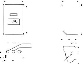
3.0MC1000 MODEL DESIGNATION CODE
The model number of an MC1000 Series drive gives a full description of the basic drive unit (see example below).
EXAMPLE: M1450BP
(MC1000, 480 Vac, 5 HP, Type 1 Enclosure, with a Remote Keypad Assembly)
Series:
M1 = M1000 Series Variable Speed AC Motor Drive
Input Voltage:
|
1 |
= |
240/120 Vac (For 110, 115, 120, 230 and 240 Vac; 50 or 60 Hz) |
||||||
|
2 |
= |
240/200 Vac (For 208, 230, and 240 Vac; 50 or 60 Hz) |
||||||
|
4 |
= |
480/400 Vac (For 380, 415, 440, 460 and 480 Vac; 50 or 60 Hz) |
||||||
|
5 |
= |
590/480 Vac (For 440, 460, 480, 575 and 600 Vac; 50 or 60 Hz) |
||||||
|
Rating: |
||||||||
|
03 |
= |
¼ HP (0.18 kW) |
75 |
= |
7½ HP (5.5 kW) |
500 |
= |
50 HP (37.5 kW) |
|
05 |
= |
½ HP (0.37 kW) |
100 |
= |
10 HP (7.5 kW) |
600 |
= |
60 HP (45 kW) |
|
10 |
= |
1 HP (0.75 kW) |
150 |
= |
15 HP (11 kW) |
750 |
= |
75 HP (55 kW) |
|
15 |
= |
1½ HP (1.1 kW) |
200 |
= |
20 HP (15 kW) |
1000 |
100 HP (75 kW) |
|
|
20 |
= |
2 HP (1.5 kW) |
250 |
= |
25 HP (18.5 kW) |
1250 |
= |
125 HP (90 kW) |
|
30 |
= |
3 HP (2.2 kW) |
300 |
= |
30 HP (22 kW) |
1500 |
= |
150 HP (110 kW) |
|
50 / 51 |
= |
5 HP (3.7 kW) |
400 |
= |
40 HP (30vkW) |
Input Phase:
S= Single phase input only.
No character indicates three phase input only
Enclosure Type:
|
B |
= NEMA 1 |
— General Purpose, vented |
|
|
C |
= NEMA 4 |
— Water-tight and Dust-tight |
|
|
D |
= |
NEMA 12 — Oil-tight and Dust-tight |
|
|
E |
= |
NEMA 4X — Water-tight, Dust-tight, and Corrosion Resistant (Stainless Steel) |
Standard Options:
|
H |
= |
Additional Form C Relay circuit board |
|
J |
= |
Dynamic Braking circuit board |
K= Dynamic Braking & Additional Form C Relay board (not available on all HP sizes — consult factory)
No character when this type of option is not specified
Interface Options:
P= Remote keypad assembly
No character when this type of option is not specified
Phone: 800.894.0412 — Fax: 208.368.0415 — Web: www.ctiautomation.net — Email: info@ctiautomation.net
4.0MC1000 DIMENSIONS
4.1TYPE 1 DIMENSIONS FOR MODELS RATED UP TO 30 HP AT 240/200 Vac AND 60 HP AT 590/480/400 Vac
|
Conduit Holes: |
W |
U |
IF W < 7.86″ |
||||||||||||||||||||||||||||||||||
|
Q |
Q |
T = 0.20″ |
|||||||||||||||||||||||||||||||||||
|
S Dia. |
V |
U = 0.34″ |
|||||||||||||||||||||||||||||||||||
|
0.88″ Dia. |
V = 0.19″ |
||||||||||||||||||||||||||||||||||||
|
S Dia. |
1.00″ |
IF W = 10.26″ |
|||||||||||||||||||||||||||||||||||
|
P |
T = 0.28″ |
||||||||||||||||||||||||||||||||||||
|
R |
|||||||||||||||||||||||||||||||||||||
|
N |
T |
U = 0.44″ |
|||||||||||||||||||||||||||||||||||
|
Dia. Slot |
V = 0.24″ |
||||||||||||||||||||||||||||||||||||
|
Mounting Tab Detail |
|||||||||||||||||||||||||||||||||||||
|
HP |
INPUT |
MODEL |
H |
W |
D |
N |
P |
Q |
R |
S |
|||||||||||||||||||||||||||
|
(kW) |
VOLTAGE |
||||||||||||||||||||||||||||||||||||
|
0.25 |
240 / 120 |
M1103SB |
7.50 |
4.70 |
3.33 |
2.35 |
1.60 |
1.37 |
5.50 |
0.88 |
|||||||||||||||||||||||||||
|
(0.18) |
|||||||||||||||||||||||||||||||||||||
|
0.5 |
240 / 120 |
M1105SB |
7.50 |
6.12 |
3.63 |
3.77 |
1.80 |
1.37 |
5.50 |
0.88 |
|||||||||||||||||||||||||||
|
240 |
M1205SB |
7.50 |
4.70 |
3.63 |
2.35 |
1.90 |
1.37 |
5.50 |
0.88 |
||||||||||||||||||||||||||||
|
(0.37) |
|||||||||||||||||||||||||||||||||||||
|
240/200 |
M1205B |
7.50 |
4.70 |
3.63 |
2.35 |
1.90 |
1.37 |
5.50 |
0.88 |
||||||||||||||||||||||||||||
|
240 / 120 |
M1110SB |
7.50 |
6.12 |
4.22 |
3.77 |
2.40 |
1.37 |
5.50 |
0.88 |
||||||||||||||||||||||||||||
|
1 |
240 |
M1210SB |
7.50 |
4.70 |
4.33 |
2.35 |
2.60 |
1.37 |
5.50 |
0.88 |
|||||||||||||||||||||||||||
|
240 / 200 |
M1210B |
7.50 |
4.70 |
4.33 |
2.35 |
2.60 |
1.37 |
5.50 |
0.88 |
||||||||||||||||||||||||||||
|
(0.75) |
|||||||||||||||||||||||||||||||||||||
|
480 / 400 |
M1410B |
7.50 |
4.70 |
3.63 |
2.35 |
1.90 |
1.37 |
5.50 |
0.88 |
||||||||||||||||||||||||||||
|
590 |
M1510B |
7.50 |
4.70 |
3.63 |
2.35 |
1.90 |
1.37 |
5.50 |
0.88 |
||||||||||||||||||||||||||||
|
1.5 |
240/120 |
M1115SB |
7.50 |
6.12 |
4.22 |
3.77 |
2.40 |
1.37 |
5.50 |
0.88 |
|||||||||||||||||||||||||||
|
240 |
M1215SB |
7.50 |
6.12 |
4.22 |
3.77 |
2.40 |
1.37 |
5.50 |
0.88 |
||||||||||||||||||||||||||||
|
(1.1) |
|||||||||||||||||||||||||||||||||||||
|
240/200 |
M1215B |
7.50 |
4.70 |
4.33 |
2.35 |
2.60 |
1.37 |
5.50 |
0.88 |
||||||||||||||||||||||||||||
|
240 |
M1220SB |
7.50 |
6.12 |
5.12 |
3.77 |
3.30 |
1.37 |
5.50 |
0.88 |
||||||||||||||||||||||||||||
|
2 |
240 / 200 |
M1220B |
7.50 |
6.12 |
5.12 |
3.77 |
3.30 |
1.37 |
5.50 |
0.88 |
|||||||||||||||||||||||||||
|
(1.5) |
480/400 |
M1420B |
7.50 |
6.12 |
4.22 |
3.77 |
2.40 |
1.37 |
5.50 |
0.88 |
|||||||||||||||||||||||||||
|
590 |
M1520B |
7.50 |
6.12 |
4.22 |
3.77 |
2.40 |
1.37 |
5.50 |
0.88 |
Phone: 800.894.0412 — Fax: 208.368.0415 — Web: www.ctiautomation.net — Email: info@ctiautomation.net
TYPE 1 DIMENSIONS (continued)
|
HP |
INPUT |
MODEL |
H |
W |
D |
N |
P |
Q |
R |
S |
|
|
(kW) |
VOLTAGE |
||||||||||
|
240 |
M1230SB |
7.50 |
6.12 |
5.12 |
3.77 |
3.30 |
1.37 |
5.50 |
0.88 |
||
|
3 |
240 / 200 |
M1230B |
7.50 |
6.12 |
5.12 |
3.77 |
3.30 |
1.37 |
5.50 |
0.88 |
|
|
(2.2) |
480 / 400 |
M1430B |
7.50 |
6.12 |
5.12 |
3.77 |
3.30 |
1.37 |
5.50 |
0.88 |
|
|
590 |
M1530B |
7.50 |
6.12 |
5.12 |
3.77 |
3.30 |
1.37 |
5.50 |
0.88 |
||
|
5 |
240 / 200 |
M1250B |
7.88 |
7.86 |
5.94 |
5.13 |
3.95 |
1.50 |
5.88 |
1.13 |
|
|
480 / 400 |
M1450B |
7.50 |
6.12 |
5.12 |
3.77 |
3.30 |
1.37 |
5.50 |
0.88 |
||
|
(3.7) |
|||||||||||
|
590 |
M1551B |
7.88 |
7.86 |
5.94 |
5.13 |
3.95 |
1.50 |
5.88 |
1.13 |
||
|
7.5 |
240 / 200 |
M1275B |
9.38 |
7.86 |
6.84 |
3.93 |
4.19 |
2.00 |
5.88 |
1.13 |
|
|
480 / 400 |
M1475B |
9.38 |
7.86 |
6.25 |
5.13 |
3.95 |
1.50 |
7.38 |
1.13 |
||
|
(5.5) |
|||||||||||
|
590 |
M1575B |
9.38 |
7.86 |
6.25 |
5.13 |
3.95 |
1.50 |
7.38 |
1.13 |
||
|
10 |
240 / 200 |
M12100B |
11.25 |
7.86 |
6.84 |
3.93 |
4.19 |
2.00 |
7.75 |
1.38 |
|
|
480 / 400 |
M14100B |
9.38 |
7.86 |
6.84 |
3.93 |
4.19 |
2.00 |
5.88 |
1.13 |
||
|
(7.5) |
|||||||||||
|
590 |
M15100B |
9.38 |
7.86 |
7.40 |
3.93 |
4.19 |
2.00 |
5.88 |
1.13 |
||
|
15 |
240/200 |
M12150B |
12.75 |
7.86 |
6.84 |
3.93 |
4.19 |
2.00 |
9.25 |
1.38 |
|
|
480/400 |
M14150B |
11.25 |
7.86 |
6.84 |
3.93 |
4.19 |
2.00 |
7.75 |
1.38 |
||
|
(11) |
|||||||||||
|
590 |
M15150B |
12.75 |
7.86 |
6.84 |
3.93 |
4.19 |
2.00 |
9.75 |
1.38 |
||
|
20 |
240 / 200 |
M12200B |
12.75 |
10.26 |
7.74 |
5.13 |
5.00 |
2.50 |
9.25 |
1.38 |
|
|
480/400 |
M14200B |
12.75 |
7.86 |
6.84 |
3.93 |
4.19 |
2.00 |
9.25 |
1.38 |
||
|
(15) |
|||||||||||
|
590 |
M15200B |
12.75 |
7.86 |
7.40 |
3.93 |
4.19 |
2.00 |
9.25 |
1.38 |
||
|
25 |
240 / 200 |
M12250B |
15.75 |
10.26 |
8.35 |
5.13 |
5.00 |
2.50 |
12.25 |
1.38 |
|
|
480/400 |
M14250B |
12.75 |
10.26 |
7.74 |
5.13 |
5.00 |
2.50 |
9.25 |
1.38 |
||
|
(18.5) |
|||||||||||
|
590 |
M15250B |
12.75 |
10.26 |
7.74 |
5.13 |
5.00 |
2.50 |
9.25 |
1.38 |
||
|
30 |
240 / 200 |
M12300B |
15.75 |
10.26 |
8.35 |
5.13 |
5.00 |
2.50 |
12.25 |
1.38 |
|
|
480/400 |
M14300B |
12.75 |
10.26 |
7.74 |
5.13 |
5.00 |
2.50 |
9.25 |
1.38 |
||
|
(22) |
|||||||||||
|
590 |
M15300B |
12.75 |
10.26 |
8.25 |
5.13 |
5.00 |
2.50 |
9.25 |
1.38 |
||
|
40 |
480/400 |
M14400B |
15.75 |
10.26 |
8.35 |
5.13 |
5.00 |
2.50 |
12.25 |
1.38 |
|
|
(30) |
590 |
M15400B |
15.75 |
10.26 |
8.35 |
5.13 |
5.00 |
2.50 |
12.25 |
1.38 |
|
|
50 |
480/400 |
M14500B |
19.75 |
10.26 |
8.55 |
5.13 |
5.75 |
2.50 |
16.25 |
1.75 |
|
|
(37.5) |
590 |
M15500B |
19.75 |
10.26 |
8.55 |
5.13 |
5.75 |
2.50 |
16.25 |
1.75 |
|
|
60 |
480/400 |
M14600B |
19.75 |
10.26 |
8.55 |
5.13 |
5.75 |
2.50 |
16.25 |
1.75 |
|
|
(45) |
590 |
M15600B |
19.75 |
10.26 |
8.55 |
5.13 |
5.75 |
2.50 |
16.25 |
1.75 |
Phone: 800.894.0412 — Fax: 208.368.0415 — Web: www.ctiautomation.net — Email: info@ctiautomation.net

4.2TYPE 1 DIMENSIONS FOR MODELS RATED ABOVE 30 HP AT 240/200 Vac AND 60 HP AT 590/480/400 Vac
|
W |
0.68″ |
||||||||||
|
IF W = 13.00″ |
0.31″ |
||||||||||
|
1.50″ |
|||||||||||
|
H |
0.36″ |
1.36″ |
|||||||||
|
Dia. |
|||||||||||
|
Mounting Tab Detail |
|||||||||||
|
0.92″ |
|||||||||||
|
Conduit Holes: |
IF W > 16.64″ |
0.43″ |
|||||||||
|
1.13″ Dia. |
|||||||||||
|
Q |
Q |
1.50″ |
|||||||||
|
S Dia. |
|||||||||||
|
0.44″ |
3.00″ |
||||||||||
|
D |
Dia. |
||||||||||
|
C |
|||||||||||
|
P |
1.36″ |
||||||||||
|
N |
|||||||||||
|
HP/kW |
INPUT |
MODEL |
H |
W |
D |
N |
C |
P |
Q |
S |
|
|
VOLTAGE |
|||||||||||
|
40/30 |
240 / 200 |
M12400B |
25.00 |
13.00 |
10.50 |
5.56 |
6.50 |
6.50 |
2.62 |
1.38 |
|
|
60/45 |
240 / 200 |
M12600B |
47.00 |
16.64 |
11.85 |
See below |
|||||
|
75/55 |
480 / 400 |
M14750B |
29.00 |
16.64 |
11.85 |
7.14 |
6.88 |
6.88 |
3.12 |
1.75 |
|
|
100/75 |
480 / 400 |
M141000B 29.00 |
24.42 |
11.85 |
11.12 |
7.25 |
6.50 |
4.50 |
2.50 |
||
|
125/90 |
480 / 400 |
M141250B 29.00 |
24.42 |
11.85 |
11.12 |
7.25 |
6.50 |
4.50 |
2.50 |
||
|
150/110 |
480 / 400 |
M141500B 29.00 |
36.66 |
11.85 |
See below |
||||||
|
CONDUIT HOLES FOR M12600B |
CONDUIT HOLES FOR M141500B |
||||||||||
|
4.26« |
4.00« |
4.00″ |
7.45« |
9.00« |
7.00″ 9.00« |
|
6.88″ |
7.25″ |
6.50″ |
|
Conduit Holes: Large holes = 1.75″ |
Conduit Holes: Large holes = 3.00″ |
|
|
Small hole = 1.13″ |
Small holes = 1.13″ |
Phone: 800.894.0412 — Fax: 208.368.0415 — Web: www.ctiautomation.net — Email: info@ctiautomation.net
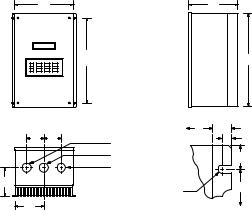
4.3TYPE 4, 4X, AND 12 DIMENSIONS FOR MODELS RATED UP TO 30 HP AT 240/200 Vac AND 60 HP AT 590/480/400 Vac
|
Conduit Holes: |
W U |
IF W < 7.86″ |
||
|
Q Q |
S Dia. |
V |
T = 0.20″ |
|
|
U = 0.34″ |
||||
|
0.88″ Dia. |
1.00″ |
|||
|
V = 0.19″ |
||||
|
S Dia. |
||||
|
P |
T |
R |
IF W > 10.26″ |
|
|
T = 0.28″ |
||||
|
Dia. Slot |
||||
|
N |
U = 0.44″ |
|||
|
Mounting Tab Detail |
V = 0.24″ |
|
HP |
INPUT |
MODEL |
H |
W |
D |
N |
P |
Q |
R |
S |
|
|
(kW) |
VOLTAGE |
||||||||||
|
0.25 |
240 / 120 |
M1103S |
7.88 |
6.12 |
3.63 |
3.06 |
2.00 |
1.37 |
5.88 |
0.88 |
|
|
(0.18) |
|||||||||||
|
0.5 |
240 / 120 |
M1105S |
7.88 |
7.86 |
3.75 |
4.80 |
2.10 |
1.37 |
5.88 |
0.88 |
|
|
240 |
M1205S |
7.88 |
6.12 |
4.35 |
3.06 |
2.70 |
1.37 |
5.88 |
0.88 |
||
|
(0.37) |
|||||||||||
|
240/200 |
M1205 |
7.88 |
6.12 |
4.35 |
3.06 |
2.70 |
1.37 |
5.88 |
0.88 |
||
|
240 / 200 |
M1110S |
7.88 |
7.86 |
4.90 |
4.80 |
3.25 |
1.37 |
5.88 |
0.88 |
||
|
1 |
240 |
M1210S |
7.88 |
6.12 |
4.35 |
3.06 |
2.70 |
1.37 |
5.88 |
0.88 |
|
|
240 / 200 |
M1210 |
7.88 |
6.12 |
4.35 |
3.06 |
2.70 |
1.37 |
5.88 |
0.88 |
||
|
(0.75) |
|||||||||||
|
480 / 400 |
M1410 |
7.88 |
6.12 |
4.35 |
3.06 |
2.70 |
1.37 |
5.88 |
0.88 |
||
|
590 |
M1510 |
7.88 |
6.12 |
4.35 |
3.06 |
2.70 |
1.37 |
5.88 |
0.88 |
||
|
1.5 |
240/120 |
M1115S |
7.88 |
7.86 |
4.90 |
4.80 |
3.25 |
1.37 |
5.88 |
0.88 |
|
|
240 |
M1215S |
7.88 |
7.86 |
4.90 |
4.80 |
3.25 |
1.37 |
5.88 |
0.88 |
||
|
(1.1) |
|||||||||||
|
240/200 |
M1215 |
7.88 |
6.12 |
5.25 |
3.06 |
3.60 |
1.37 |
5.88 |
0.88 |
||
|
240 |
M1220S |
7.88 |
7.86 |
4.90 |
4.80 |
3.25 |
1.37 |
5.88 |
0.88 |
||
|
2 |
240 / 200 |
M1220 |
7.88 |
7.86 |
4.90 |
4.80 |
3.25 |
1.37 |
5.88 |
0.88 |
|
|
(1.5) |
480/400 |
M1420 |
7.88 |
7.86 |
4.90 |
4.80 |
3.25 |
1.37 |
5.88 |
0.88 |
|
|
590 |
M1520 |
7.88 |
7.86 |
4.90 |
4.80 |
3.25 |
1.37 |
5.88 |
0.88 |
||
|
240 |
M1230S |
7.88 |
7.86 |
5.90 |
4.80 |
4.25 |
1.37 |
5.88 |
0.88 |
||
|
3 |
240 / 200 |
M1230 |
7.88 |
7.86 |
5.90 |
4.80 |
4.25 |
1.37 |
5.88 |
0.88 |
|
|
(2.2) |
480 / 400 |
M1430 |
7.88 |
7.86 |
4.90 |
4.80 |
3.25 |
1.37 |
5.88 |
0.88 |
|
|
590 |
M1530 |
7.88 |
7.86 |
4.90 |
4.80 |
3.25 |
1.37 |
5.88 |
0.88 |
Phone: 800.894.0412 — Fax: 208.368.0415 — Web: www.ctiautomation.net — Email: info@ctiautomation.net
DIMENSIONS — TYPE 4, 4X, AND 12 ENCLOSED (continued)
|
HP |
INPUT |
MODEL |
H |
W |
D |
N |
P |
Q |
R |
S |
|
|
(kW) |
VOLTAGE |
||||||||||
|
5 |
240 / 200 |
M1250 |
9.75 |
10.26 |
7.20 |
5.13 |
5.25 |
2.00 |
7.75 |
1.13 |
|
|
480 / 400 |
M1450 |
7.88 |
7.86 |
5.90 |
4.80 |
4.25 |
1.37 |
5.88 |
0.88 |
||
|
(3.7) |
|||||||||||
|
590 |
M1550 |
7.88 |
7.86 |
5.90 |
4.80 |
4.25 |
1.37 |
5.88 |
0.88 |
||
|
7.5 |
240 / 200 |
M1275 |
11.75 |
10.26 |
8.35 |
5.13 |
5.75 |
2.00 |
9.75 |
1.13 |
|
|
480 / 400 |
M1475 |
9.75 |
10.26 |
7.20 |
5.13 |
5.25 |
2.00 |
7.75 |
1.13 |
||
|
(5.5) |
|||||||||||
|
590 |
M1575 |
9.75 |
10.26 |
7.20 |
5.13 |
5.25 |
2.00 |
7.75 |
1.13 |
||
|
10 |
240 / 200 |
M12100 |
13.75 |
10.26 |
8.35 |
5.13 |
5.75 |
2.00 |
11.75 |
1.38 |
|
|
480 / 400 |
M14100 |
11.75 |
10.26 |
8.35 |
5.13 |
5.75 |
2.00 |
9.75 |
1.13 |
||
|
(7.5) |
|||||||||||
|
590 |
M15100 |
11.75 |
10.26 |
8.35 |
5.13 |
5.75 |
2.00 |
9.75 |
1.13 |
||
|
15 |
240/200 |
M12150 |
15.75 |
10.26 |
8.35 |
5.13 |
5.75 |
2.00 |
13.75 |
1.38 |
|
|
480/400 |
M14150 |
13.25 |
10.26 |
8.35 |
5.13 |
5.75 |
2.00 |
11.75 |
1.38 |
||
|
(11) |
|||||||||||
|
590 |
M15150 |
13.75 |
10.26 |
8.35 |
5.13 |
5.75 |
2.00 |
11.75 |
1.38 |
||
|
20 |
240 / 200 |
M12200D* 15.75 |
10.26 |
8.35 |
5.13 |
5.75 |
2.00 |
11.75 |
1.38 |
||
|
480/400 |
M14200 |
15.75 |
10.26 |
8.35 |
5.13 |
5.75 |
2.00 |
13.75 |
1.38 |
||
|
(15) |
|||||||||||
|
590 |
M15200 |
15.75 |
10.26 |
8.35 |
5.13 |
5.75 |
2.00 |
13.75 |
1.38 |
||
|
25 |
240 / 200 |
M12250D* 20.25 |
10.26 |
8.35 |
5.13 |
5.75 |
2.00 |
16.25 |
1.38 |
||
|
480/400 |
M14250D* 15.75 |
10.26 |
8.35 |
5.13 |
5.75 |
2.00 |
11.75 |
1.38 |
|||
|
(18.5) |
|||||||||||
|
590 |
M15250D* 15.75 |
10.26 |
8.35 |
5.13 |
5.75 |
2.00 |
11.75 |
1.38 |
|||
|
30 |
240 / 200 |
M12300D* 20.25 |
10.26 |
8.35 |
5.13 |
5.75 |
2.00 |
16.25 |
1.38 |
||
|
480/400 |
M14300D* 15.75 |
10.26 |
8.35 |
5.13 |
5.75 |
2.00 |
11.75 |
1.38 |
|||
|
(22) |
|||||||||||
|
590 |
M15300D* 15.75 |
10.26 |
8.35 |
5.13 |
5.75 |
2.00 |
11.75 |
1.38 |
|||
|
40 |
480/400 |
M14400D* 20.25 |
10.26 |
8.35 |
5.13 |
5.75 |
2.00 |
16.25 |
1.38 |
||
|
(30) |
590 |
M15400D* 20.25 |
10.26 |
8.35 |
5.13 |
5.75 |
2.00 |
16.25 |
1.38 |
||
|
50 |
480/400 |
M14500D* 21.00 |
13.72 |
8.35 |
5.13 |
6.10 |
2.00 |
16.25 |
1.38 |
||
|
(37.5) |
590 |
M15500D* 21.00 |
13.72 |
8.35 |
5.13 |
6.10 |
2.00 |
16.25 |
1.38 |
||
|
60 |
480/400 |
M14600D* 21.00 |
13.72 |
8.35 |
5.13 |
6.10 |
2.00 |
16.25 |
1.38 |
||
|
(45) |
590 |
M15600D* 21.00 |
13.72 |
8.35 |
5.13 |
6.10 |
2.00 |
16.25 |
1.38 |
*Models available in NEMA 12 only.
Phone: 800.894.0412 — Fax: 208.368.0415 — Web: www.ctiautomation.net — Email: info@ctiautomation.net
![]()
4.4TYPE 12 DIMENSIONS FOR MODELS RATED ABOVE 30 HP AT 240/200 Vac AND 60 HP AT 590/480/400 Vac
|
W |
0.68″ |
|||||||||
|
R |
0.31″ |
|||||||||
|
1.36″ |
||||||||||
|
H |
0.36″ |
1.50″ |
||||||||
|
Dia. |
||||||||||
|
IF W = 14.00″ |
||||||||||
|
Mounting Tab Detail |
||||||||||
|
0.92″ |
||||||||||
|
Q Q |
Conduit Holes: |
0.43″ |
||||||||
|
1.13″ Dia. |
1.36″ |
|||||||||
|
S Dia. |
||||||||||
|
D |
0.44″ |
3.00″ |
||||||||
|
Dia. |
||||||||||
|
P |
||||||||||
|
IF W > 18.00″ |
1.50″ |
|||||||||
|
N |
||||||||||
|
HP/kW |
INPUT |
MODEL |
H |
W |
D |
N |
P |
Q |
R |
S |
|
VOLTAGE |
||||||||||
|
40/30 |
240 / 200 |
M12400D |
31.00 |
14.00 |
11.86 |
6.00 |
7.50 |
2.62 |
5.64 |
1.38 |
|
60/45 |
240 / 200 |
M12600D |
49.00 |
18.00 |
13.30 |
7.50 |
8.00 |
3.13 |
7.14 |
1.75 |
|
75/55 |
480 / 400 |
M14750D |
37.00 |
18.00 |
13.30 |
7.50 |
8.00 |
3.13 |
7.14 |
1.75 |
|
100/75 |
480 / 400 |
M141000D 39.00 |
26.00 |
13.30 |
11.50 |
9.00 |
4.50 |
9.14 |
2.50 |
|
|
125/90 |
480 / 400 |
M141250D 39.00 |
26.00 |
13.30 |
11.50 |
9.00 |
4.50 |
9.14 |
2.50 |
Phone: 800.894.0412 — Fax: 208.368.0415 — Web: www.ctiautomation.net — Email: info@ctiautomation.net

5.0MC1000 RATINGS
The following tables indicate the input and output ratings of the MC1000 Series.
NOTE: The output current ratings are based on operation at carrier frequencies of 8 kHz and below. At full ambient temperature, operation at carrier frequencies above 8 kHz require derating the drive by multiplying the output current rating by the following factors: 0.94 at 10 kHz, 0.89 at 12 kHz, and 0.83 at 14 kHz. Refer to
Parameter 23 — CARRIER in Section 18.0 — DESCRIPTION OF PARAMETERS.
M1100 SERIES RATINGS
|
MODEL |
INPUT |
OUTPUT |
|||||
|
(120/240 Vac, 50 — 60 Hz) |
(0 — 230 Vac) |
||||||
|
FOR MOTORS |
NOMINAL |
NOMINAL |
|||||
|
MODEL |
RATED |
INPUT |
CURRENT2 |
POWER |
CURRENT |
POWER |
|
|
1 |
|||||||
|
NUMBER |
|||||||
|
HP |
kW |
PHASE |
(AMPS) |
(KVA) |
(AMPS) |
(KVA) |
|
|
M1103S |
0.25 |
0.18 |
1 |
6.0 / 3.0 |
0.72 |
1.4 / 1.4 |
0.56 |
|
M1105S |
0.5 |
0.37 |
1 |
9.2 / 4.6 |
1.1 |
2.2 / 2.2 |
0.88 |
|
M1110S |
1 |
0.75 |
1 |
16.2 / 8.1 |
1.9 |
4.0 / 4.0 |
1.6 |
|
M1115S |
1.5 |
1.1 |
1 |
21 / 10.4 |
2.5 |
5.2 / 5.2 |
2.1 |
1See Section 3.0 for model number breakdown.
2See Section 8.0 for recommended fuse type.
Phone: 800.894.0412 — Fax: 208.368.0415 — Web: www.ctiautomation.net — Email: info@ctiautomation.net

M1200 SERIES RATINGS
|
MODEL |
INPUT |
OUTPUT |
|||||||
|
(200/240 Vac, 50 — 60 Hz) |
(0 — 200/230 Vac) |
||||||||
|
FOR MOTORS |
NOMINAL |
NOMINAL |
|||||||
|
MODEL |
RATED |
INPUT |
CURRENT2 |
POWER |
CURRENT |
POWER |
|||
|
1 |
|||||||||
|
NUMBER |
|||||||||
|
HP |
kW |
PHASE |
(AMPS) |
(KVA) |
(AMPS) |
(KVA) |
|||
|
M1205S |
0.5 |
0.37 |
1 |
5.8 |
/ 5.0 |
1.2 |
2.5 |
/ 2.2 |
0.9 |
|
M1205 |
0.5 |
0.37 |
3 |
3.1 |
/ 2.7 |
1.1 |
2.5 |
/ 2.2 |
0.9 |
|
M1210S |
1 |
0.75 |
1 |
10.4 / 9.0 |
2.2 |
4.6 |
/ 4.0 |
1.6 |
|
|
M1210 |
1 |
0.75 |
3 |
5.5 |
/ 4.8 |
2.0 |
4.6 |
/ 4.0 |
1.6 |
|
M1215S |
1.5 |
1.1 |
1 |
13.3 |
/ 11.6 |
2.8 |
6.0 |
/ 5.2 |
2.1 |
|
M1215 |
1.5 |
1.1 |
3 |
7.1 |
/ 6.2 |
2.6 |
6.0 |
/ 5.2 |
2.1 |
|
M1220S |
2 |
1.5 |
1 |
17.1 |
/ 14.9 |
3.6 |
7.8 |
/ 6.8 |
2.7 |
|
M1220 |
2 |
1.5 |
3 |
9.3 |
/ 8.1 |
3.4 |
7.8 |
/ 6.8 |
2.7 |
|
M1230S |
3 |
2.2 |
1 |
24 |
/ 21 |
5.0 |
11.0 / 9.6 |
3.8 |
|
|
M1230 |
3 |
2.2 |
3 |
13.0 |
/ 11.3 |
4.7 |
11.0 / 9.6 |
3.8 |
|
|
M1250 |
5 |
3.7 |
3 |
20 / 17.7 |
7.4 |
17.5 |
/ 15.2 |
6.1 |
|
|
M1275 |
7.5 |
5.5 |
3 |
30 |
/ 26 |
10.6 |
25 |
/ 22 |
8.8 |
|
M12100 |
10 |
7.5 |
3 |
37 |
/ 32 |
13.2 |
32 |
/ 28 |
11.2 |
|
M12150 |
15 |
11 |
3 |
55 |
/ 48 |
19.8 |
48 |
/ 42 |
16.7 |
|
M12200 |
20 |
15 |
3 |
70 |
/ 61 |
25.3 |
62 |
/ 54 |
21.5 |
|
M12250 |
25 |
18.5 |
3 |
89 |
/ 77 |
32.0 |
78 |
/ 68 |
27.1 |
|
M12300 |
30 |
22 |
3 |
104 / 90 |
37.6 |
92 |
/ 80 |
31.9 |
|
|
M12400 |
40 |
30 |
3 |
119 / 99 |
41.0 |
120 |
/ 104 |
41.4 |
|
|
M12600 |
60 |
45 |
3 |
174 |
/ 145 |
60.5 |
177 |
/ 154 |
61.3 |
1See Section 3.0 for model number breakdown.
2See Section 8.0 for recommended fuse type.
Phone: 800.894.0412 — Fax: 208.368.0415 — Web: www.ctiautomation.net — Email: info@ctiautomation.net

M1400 SERIES RATINGS
|
MODEL |
INPUT |
OUTPUT |
|||||||
|
(400/480 Vac, 50 — 60 Hz) |
(0 — 400/460 Vac) |
||||||||
|
FOR MOTORS |
NOMINAL |
NOMINAL |
|||||||
|
MODEL |
RATED |
INPUT |
CURRENT2 |
POWER |
CURRENT |
POWER |
|||
|
1 |
|||||||||
|
NUMBER |
|||||||||
|
HP |
kW |
PHASE |
(AMPS) |
(KVA) |
(AMPS) |
(KVA) |
|||
|
M1410 |
1 |
0.75 |
3 |
2.8 |
/ 2.4 |
2.0 |
2.3 |
/ 2.0 |
1.6 |
|
M1420 |
2 |
1.5 |
3 |
4.7 |
/ 4.1 |
3.4 |
3.9 |
/ 3.4 |
2.7 |
|
M1430 |
3 |
2.2 |
3 |
6.6 |
/ 5.7 |
4.7 |
5.5 |
/ 4.8 |
3.8 |
|
M1450 |
5 |
3.7 |
3 |
10.2 / 8.9 |
7.3 |
8.7 |
/ 7.6 |
6.1 |
|
|
M1475 |
7.5 |
5.5 |
3 |
14.7 |
/ 12.8 |
10.6 |
12.6 |
/ 11.0 |
8.8 |
|
M14100 |
10 |
7.5 |
3 |
18.3 |
/ 15.9 |
13.2 |
16.0 |
/ 14.0 |
11.2 |
|
M14150 |
15 |
11 |
3 |
28 |
/ 24 |
19.8 |
24 |
/ 21 |
16.7 |
|
M14200 |
20 |
15 |
3 |
36 |
/ 31 |
25.3 |
31 |
/ 27 |
21.5 |
|
M14250 |
25 |
18.5 |
3 |
44 |
/ 38 |
31.9 |
39 |
/ 34 |
27.1 |
|
M14300 |
30 |
22 |
3 |
52 |
/ 45 |
37.6 |
46 |
/ 40 |
31.9 |
|
M14400 |
40 |
30 |
3 |
68 |
/ 59 |
49.0 |
60 |
/ 52 |
41.4 |
|
M14500 |
50 |
37.5 |
3 |
85 |
/ 74 |
61.5 |
75 |
/ 65 |
51.8 |
|
M14600 |
60 |
45 |
3 |
100 / 87 |
72.3 |
88 |
/ 77 |
61.3 |
|
|
M14750 |
75 |
55 |
3 |
109 / 91 |
75.5 |
110 / 96 |
76.5 |
||
|
M141000 |
100 |
75 |
3 |
139 |
/ 116 |
96.4 |
143 |
/ 124 |
98.8 |
|
M141250 |
125 |
90 |
3 |
175 |
/ 146 |
121.4 |
179 |
/ 156 |
124.3 |
|
M141500 |
150 |
110 |
3 |
202 |
/ 168 |
139.7 |
207 |
/ 180 |
143.4 |
1See Section 3.0 for model number breakdown.
2See Section 8.0 for recommended fuse type.
Phone: 800.894.0412 — Fax: 208.368.0415 — Web: www.ctiautomation.net — Email: info@ctiautomation.net

M1500 SERIES RATINGS
|
MODEL |
INPUT |
OUTPUT |
|||||||
|
(480/590 Vac, 50 — 60 Hz) |
(0 — 460/575 Vac) |
||||||||
|
FOR MOTORS |
NOMINAL |
NOMINAL |
|||||||
|
MODEL |
RATED |
INPUT |
CURRENT2 |
POWER |
CURRENT |
POWER |
|||
|
1 |
|||||||||
|
NUMBER |
|||||||||
|
HP |
kW |
PHASE |
(AMPS) |
(KVA) |
(AMPS) |
(KVA) |
|||
|
M1510 |
1 |
0.75 |
3 |
1.9 |
/ 1.9 |
1.9 |
1.6 |
/ 1.6 |
1.6 |
|
M1520 |
2 |
1.5 |
3 |
3.3 |
/ 3.3 |
3.4 |
2.7 |
/ 2.7 |
2.7 |
|
M1530 |
3 |
2.2 |
3 |
4.6 |
/ 4.6 |
4.7 |
3.9 |
/ 3.9 |
3.9 |
|
M1550/51 |
5 |
3.7 |
3 |
7.1 |
/ 7.1 |
7.3 |
6.1 |
/ 6.1 |
6.1 |
|
M1575 |
7.5 |
5.5 |
3 |
10.5 |
/ 10.5 |
10.7 |
9.0 |
/ 9.0 |
8.8 |
|
M15100 |
10 |
7.5 |
3 |
12.5 |
/ 12.5 |
12.8 |
11.0 |
/ 11.0 |
11.0 |
|
M15150 |
15 |
11 |
3 |
19.3 |
/ 19.3 |
19.7 |
17.0 |
/ 17.0 |
16.9 |
|
M15200 |
20 |
15 |
3 |
25 |
/ 25 |
25.4 |
22 |
/ 22 |
21.5 |
|
M15250 |
25 |
18.5 |
3 |
31 |
/ 31 |
31.2 |
27 |
/ 27 |
26.9 |
|
M15300 |
30 |
22 |
3 |
36 |
/ 36 |
37.1 |
32 |
/ 32 |
31.9 |
|
M15400 |
40 |
30 |
3 |
47 |
/ 47 |
47.5 |
41 |
/ 41 |
40.8 |
|
M15500 |
50 |
37.5 |
3 |
59 |
/ 59 |
60.3 |
52 |
/ 52 |
51.8 |
|
M15600 |
60 |
45 |
3 |
71 |
/ 71 |
72.5 |
62 |
/ 62 |
61.7 |
1See Section 3.0 for model number breakdown.
2See Section 8.0 for recommended fuse type.
Phone: 800.894.0412 — Fax: 208.368.0415 — Web: www.ctiautomation.net — Email: info@ctiautomation.net

6.0THEORY
6.1DESCRIPTION OF AC MOTOR OPERATION
Three phase AC motors are comprised of two major components, the stator and the rotor. The stator is a set of three electrical windings held stationary in the motor housing. The rotor is a metal cylinder, fixed to the motor drive shaft, which rotates within the stator. The arrangement of the stator coils and the presence of three phase AC voltage give rise to a rotating magnetic field which drives the rotor. The speed at which the magnetic field rotates is known as the synchronous speed of the motor. Synchronous speed is a function of the frequency at which the voltage is alternating and the number of poles in the stator windings.
The following equation gives the relation between synchronous speed, frequency, and the number of poles:
Ss = 120 f/p
Where: Ss = Synchronous speed (rpm ), f = frequency (Hz), p = number of poles
In three phase induction motors the actual shaft speed differs from the synchronous speed as load is applied. This difference is known as “slip”. Slip is commonly expressed as a percentage of synchronous speed. A typical value is three percent at full load.
The strength of the magnetic field in the gap between the rotor and stator is proportional to the amplitude of the voltage at a given frequency. The output torque capability of the motor is, therefore, a function of the applied voltage amplitude at a given frequency. When operated below base (rated) speed, AC motors run in the range of “constant torque”. Constant torque output is obtained by maintaining a constant ratio between voltage amplitude (Volts) and frequency (Hertz). For 60 Hz motors rated at 230, 460, and 575 Vac, common values for this V/Hz ratio are 3.83, 7.66, and 9.58 respectively. Operating with these V/Hz ratios generally yields optimum torque capability. Operating at lower ratio values results in lower torque and power capability. Operating at higher ratio values will cause the motor to overheat. Most standard motors are capable of providing full torque output from 3 to 60 Hz. However, at lower speeds, where motor cooling fans become less effective, supplemental cooling may be needed to operate at full torque output continuously.
If the frequency applied to the motor is increased while the voltage remains constant, torque capability will decrease as speed increases. This will cause the horsepower capability of the motor to remain approximately constant. Motors run in this mode when operated above base speed, where drive output voltage is limited by the input line voltage. This operating range is known as the “constant horsepower” range. The typical maximum range for constant horsepower is about 2.3 to 1
(60 to 140 Hz). The diagram below depicts the characteristics of a typical AC induction motor with a 60 Hz base speed.
WARNING!
Consult motor manufacturer before operating motor and/or driven equipment above base speed.
Phone: 800.894.0412 — Fax: 208.368.0415 — Web: www.ctiautomation.net — Email: info@ctiautomation.net
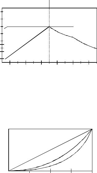
TORQUE (%)
150 
130 
110 
90 
70 
50
30 
10 
CONSTANT TORQUE
TORQUE
HORSEPOWER
CONSTANT HP
HORSEPOWER TORQUE
|
20 |
40 |
60 |
80 |
100 |
120 |
FREQUENCY (Hz)
6.1.1VARIABLE TORQUE VS. CONSTANT TORQUE
Variable frequency drives, and the loads they are applied to, can generally be divided into two groups: constant torque and variable torque. Constant torque loads include: vibrating conveyors, punch presses, rock crushers, machine tools, and just about every other application that is not considered variable torque. Variable torque loads include centrifugal pumps and fans, which make up the majority of HVAC applications.
Variable torque loads are governed by the affinity laws, which define the relationships between speed, flow, torque and horsepower. The diagram below illustrates these relationships:
100% 
75% 
|
FLOW |
||
|
% |
TORQUE |
|
|
% |
HORSEPOWER |
|
|
% |
|
0% |
25% |
50% |
75% |
100% |
% SPEED
“Variable torque” refers to the fact that the torque required varies with the square of the speed. Also, the horsepower required varies with the cube of the speed, resulting in a large reduction in horsepower for even a small reduction in speed. It is easily seen that substantial energy savings can be achieved by reducing the speed of a fan or pump. For example, reducing the speed to 50% results in a 50 HP motor having to produce only 12.5% of rated horsepower, or 6.25 HP.
Phone: 800.894.0412 — Fax: 208.368.0415 — Web: www.ctiautomation.net — Email: info@ctiautomation.net
Variable torque drives usually have a low overload capacity (110% — 120% for 60 seconds), because variable torque applications rarely experience overload conditions. To optimize efficiency and energy savings, variable torque drives are usually programmed to follow a variable V/Hz ratio.
The term “constant torque” is not entirely accurate in terms of the actual torque required for an application. Many constant torque applications have reciprocating loads, such as vibrating conveyors and punch presses, where the rotational motion of the motor is being converted to a linear motion. In such cases, the torque required can vary greatly at different points in the cycle. For constant torque loads, this
fluctuation in torque is not a direct function of speed, as it is with a variable torque load. As a result, constant torque drives typically have a high overload rating (150% for 60 seconds) in order to handle the higher peak torque demands. To achieve maximum torque, constant torque drives follow a constant V/Hz ratio.
Both MC Series product lines (MC1000 and MC3000) have full overload capacity (150% for 60 seconds, 180% for 30 seconds), so that either one can be used for either type of application. The V/Hz ratio can also be changed to optimize performance for either type of application.
Phone: 800.894.0412 — Fax: 208.368.0415 — Web: www.ctiautomation.net — Email: info@ctiautomation.net
6.2DRIVE FUNCTION DESCRIPTION
The MC Series is a 16 bit microprocessor based, keypad programmable, variable speed AC motor drive. There are four major sections: an input diode bridge and filter, a power board, a control board, and an output intelligent power module.
6.2.1DRIVE OPERATION
Incoming AC line voltage is converted to a pulsating DC voltage by the input diode bridge. The DC voltage is supplied to the bus filter capacitors through a charge circuit which limits inrush current to the capacitors during power-up. The pulsating DC voltage is filtered by the bus capacitors which reduces the ripple level. The filtered DC voltage enters the inverter section of the drive, composed of six output intelligent insulated gate bi-polar transistors (IGBTs) which make up the three output legs of the drive. Each leg has one intelligent IGBT connected to the positive bus voltage and one connected to the negative bus voltage. Alternately switching on each leg, the intelligent IGBT produces an alternating voltage on each of the corresponding motor windings. By switching each output intelligent IGBT at a very high frequency (known as the carrier frequency) for varying time intervals, the inverter is able to produce a smooth, three phase, sinusoidal output current wave which optimizes motor performance.
6.2.2CIRCUIT DESCRIPTION
The control section consists of a control board with a 16 bit microprocessor, keypad and display. Drive programming is accomplished via the keypad or the serial communications port. During operation the drive can be controlled via the keypad, by control devices wired to the control terminal strip, or by the serial communications port. The Power Board contains the control and protection circuits which govern the six output IGBTs. The Power Board also contains a charging circuit for the bus
filter capacitors, a motor current feedback circuit, a voltage feedback circuit, and a fault signal circuit. The drive has several built in protection circuits. These include phase-to-phase and phase-to-ground short circuit protection, high and low line voltage protection, protection against excessive ambient temperature, and protection against continuous excessive output current. Activation of any of these circuits will cause the drive to shut down in a fault condition.
6.2.3MC1000 INPUTS AND OUTPUTS
The drive has two analog inputs (0-10 VDC and 4-20 mA) that can be used for speed reference, PID set point reference, or PID feedback. A speed potentiometer
(10,000 Ohm) can be used with the 0-10 VDC input.
There are also two analog outputs: one is proportional to speed (frequency), and the other is proportional to load.
The drive has three programmable outputs for status indication: one Form C relay and two open-collector outputs.
NOTE: Models rated above 30 Hp at 200/240 Vac and 60 Hp at 400/480 Vac have a second Form C relay.
Refer to Sections 14.0 — CONTROL WIRING and 15.0 — CONTROL WIRING DIAGRAMS for more information.
Phone: 800.894.0412 — Fax: 208.368.0415 — Web: www.ctiautomation.net — Email: info@ctiautomation.net
7.0INSTALLATION
WARNING!
DRIVES MUST NOT BE INSTALLED WHERE SUBJECTED TO ADVERSE
ENVIRONMENTAL CONDITIONS! DRIVES MUST NOT BE INSTALLED WHERE SUBJECTED TO: COMBUSTIBLE, OILY, OR HAZARDOUS VAPORS OR DUST; EXCESSIVE MOISTURE OR DIRT; STRONG VIBRATION; EXCESSIVE AMBIENT TEMPERATURES. CONSULT AC TECHNOLOGY FOR MORE INFORMATION ON THE SUITABILITY OF A DRIVE TO A PARTICULAR
ENVIRONMENT.
The drive should be mounted on a smooth vertical surface capable of safely supporting the unit without vibrating. The LCD display has an optimum field of view, this should be considered when determining the mounting position.
Chassis models must be installed in an electrical enclosure which will provide complete mechanical protection and maintain uniform internal temperature within the drive’s ambient operating temperature rating. All drive models MUST be mounted in a vertical position for proper heatsink cooling.
Maintain a minimum spacing around the drive as follows:
SPACING REQUIREMENTS
SPACING
HP
INCHES mm
0.25 — 5 2 50
7.5 — 25 4 100
30 — 60 6 150
75 — 150 8 200
All drive models MUST be mounted in a vertical position for proper heatsink cooling. Fans or blowers should be used to insure proper cooling in tight quarters. Do not mount drives above other drives or heat producing equipment that would impede the cooling of the drive. Note the ambient operating temperature ratings for each drive model.
If it is necessary to drill or cut the drive enclosure or panel, extreme care must be taken to avoid damaging drive components or contaminating the drive with metal fragments (which cause shorting of electrical circuits). Cover drive components with a clean cloth to keep out metal chips and other debris. Use a vacuum cleaner to clean drive components after drilling, even if chips do not appear to be present. Do not attempt to use positive air pressure to blow chips out of drive, as this tends to lodge debris under electronic components. Contaminating the drive with metal chips can cause drive failure and will void the warranty.The MC1000 Series is UL approved for solid state motor overload protection. Therefore, a separate thermal overload relay is not required for single motor applications. In applications where one drive is operating more than one motor, a separate thermal overload relay is required for each motor per NEC.
Phone: 800.894.0412 — Fax: 208.368.0415 — Web: www.ctiautomation.net — Email: info@ctiautomation.net
![]()
7.1INSTALLATION AFTER A LONG PERIOD OF STORAGE
WARNING!
Severe damage to the drive can result if it is operated after a long period of storage or inactivity without reforming the DC bus capacitors!
If input power has not been applied to the drive for a period of time exceeding three years (due to storage, etc), the electrolytic DC bus capacitors within the drive can change internally, resulting in excessive leakage current. This can result in premature failure of the capacitors if the drive is operated after such a long period of inactivity or storage.
In order to reform the capacitors and prepare the drive for operation after a long period of inactivity, apply input power to the drive for 8 hours prior to actually operating the drive/motor system.
7.2EXPLOSION PROOF APPLICATIONS
Explosion proof motors that are not rated for inverter use lose their certification when used for variable speed. Due to the many areas of liability that may be encountered when dealing with these applications, the following statement of policy applies:
“AC Technology Corporation inverter products are sold with no warranty of fitness for a particular purpose or warranty of suitability for use with explosion proof motors. AC Technology Corporation accepts no responsibility for any direct,incidentalorconsequentialloss,cost,ordamagethatmayarisethrough the use of its AC inverter products in these applications. The purchaser expressly agrees to assume all risk of any loss, cost, or damage that may arise from such application.»
Phone: 800.894.0412 — Fax: 208.368.0415 — Web: www.ctiautomation.net — Email: info@ctiautomation.net

8.0INPUT AC REQUIREMENTS
WARNING!
Hazard of electrical shock! Disconnect incoming power and wait three minutes before servicing the drive. Capacitors retain charge after power is removed.
8.1INPUT AC POWER REQUIREMENTS
8.1.1VOLTAGE
The input voltage must match the drive’s nameplate voltage rating. Voltage
fluctuation must not vary by greater than 10% over voltage or 15% under voltage.
NOTE: Drives with dual rated input voltage must be programmed for the proper supply voltage. Refer to Parameter 0 — LINE VOLTS in Section 18.0 — DESCRIPTION OF PARAMETERS.
The UL file for this drive shows that it is suitable for use on a circuit capable of delivering not more than 200,000 RMS symmetrical amperes, at the drive’s rated voltage. The CSA file identifies a short-circuit withstand rating of 5,000 RMS symmetrical amperes at the drives rated voltage.
Three phase voltage imbalance must be less than 2.0% phase to phase. Excessive phase to phase imbalance can cause severe damage to the drive’s power components.
Motor voltage should match line voltage in normal applications. The drive’s maximum output voltage will equal the input voltage. Use extreme caution when using a motor with a voltage rating which is different from the input line voltage.
8.1.2SUPPLY TRANSFORMER kVA RATINGS
If the kVA rating of the AC supply transformer is greater than ten times the input kVA rating of the drive, a drive isolation transformer, or a 2 — 3% input line reactor (also known as a choke) must be added.
8.2INPUT FUSING AND DISCONNECT REQUIREMENTS
A circuit breaker or a disconnect switch with fuses must be provided in accordance with the National Electric Code (NEC) and all local codes.
The MC1000 drive is capable of withstanding up to 150% current overload for 60 seconds. Select a fuse or magnetic trip circuit breaker rated at 1.5 times the input current rating of the drive (the minimum size should be 10 amps, regardless of input current rating). Refer to Section 5.0 — MC1000 RATINGS.Minimum voltage rating of the protection device should be 250 Vac for 240/120 Vac and 240/200 Vac rated drives, and 600 Vac for 480/400 Vac and 590/480 Vac drives.
Use UL Class CC or Class T current-limiting type fuses with low I2 T values, rated at 200,000 AIC. Recommended fuses are Bussman type KTK-R, JJN, and JJS, or equivalent.
Phone: 800.894.0412 — Fax: 208.368.0415 — Web: www.ctiautomation.net — Email: info@ctiautomation.net

9.0VOLTAGE SELECTION
M1100 Series drives are rated for 240/120 Vac, 50-60 Hz input. The drive will function with input voltage of 120 Vac (+ 10%, -15%) at 48 to 62 Hz when wired for 120 Vac input, or with input voltage of 240 Vac (+ 10%, — 15%), at 48 to 62 Hz, when wired for 240 Vac input.
M1200Seriesdrives are rated for 240/200 Vac, 50-60 Hz input. The drive will function with input voltages of 200 to 240 Vac (+ 10%, — 15%), at 48 to 62 Hz.
M1400 Series drives are rated for 480/400 Vac, 50-60 Hz input. The drive will function with input voltages of 400 to 480 Vac (+ 10%, — 15%), at 48 to 62 Hz.
M1500 Series drives are rated for 590/480 Vac, 50-60 Hz input. The drive will function with input voltages of 480 to 590 Vac (+ 10%, — 15%), at 48 to 62 Hz.
10.0 POWER WIRING
WARNING!
Hazard of electrical shock! Wait three minutes after disconnecting incoming power before servicing drive. Capacitors retain charge after power is removed.
Note drive input and output current ratings and check applicable electrical codes for required wire type and size, grounding requirements, over current protection, and incoming power disconnect, before wiring the drive. Size conservatively to minimize voltage drop.
Input fusing and a power disconnect switch or contactor MUST be wired in series with terminals L1, L2, and L3 (L1 and L2 if input is single phase). If one has not been supplied by AC Technology Corporation, a disconnect means must be wired during installation. This disconnect must be used to power down the drive when servicing, or when the drive is not to be operated for a long period of time, but should not be used to start and stop the motor.
Repetitive cycling of a disconnect or input contactor (more than once every two minutes) may cause damage to the drive.
10.1WIRING FOR SINGLE PHASE OR THREE PHASE INPUT
If the drive is name plated for 240/120 Vac single phase input, wire the input to terminals L1 and N and jumper terminals L1 to L2 for 120 Vac input voltage, or wire to terminals L1 and L2 (do not wire to N) for 240 Vac input voltage. Refer to Section 11.0 — MC1000 POWER WIRING DIAGRAM.
If the drive is name plated for three phase input only, wire the input to terminals L1, L2, and L3.
All three power output wires, from terminals T1, T2, and T3 to the motor, must be kept tightly bundled and run in a separate conduit away from all other power and control wiring.
It is not recommended to install contactors or disconnect switches between the drive and motor. Operating such devices while the drive is running can potentially cause damage to the drive’s power components. If such a device is required, it should only be operated when the drive is in a STOP state. If there is potential for the device to be opened while the drive is running, the drive must be programmed for COAST TO STOP (see Parameter 26 — STOP), and an auxiliary contact on the device must be interlocked with the drive’s run circuit. This will give the drive a stop command at the same time the device opens, and will not allow the drive to start again until the device is closed.
Phone: 800.894.0412 — Fax: 208.368.0415 — Web: www.ctiautomation.net — Email: info@ctiautomation.net
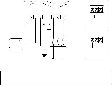
11.0 MC1000 POWER WIRING DIAGRAM
|
L1 L2 N |
||||||
|
T1 |
T2 |
T3 |
L1 |
L2 |
L3 |
|
|
GND GND |
120 Vac SINGLE |
|||||
|
PHASE INPUT |
||||||
|
WIRING DIAGRAM |
||||||
|
L1 L2 N |
||||||
|
DISCONNECT |
240 Vac SINGLE |
|||||
|
MEANS |
||||||
|
THREE PHASE |
PHASE INPUT |
|||||
|
(REQUIRED) |
||||||
|
WIRING DIAGRAM |
||||||
|
AC MOTOR |
GND |
|||||
FUSED INPUT
VOLTAGE
WARNING!
Do not connect incoming AC power to output terminals T1, T2, or T3! Severe damage to the drive will result.
INSTALL, WIRE, AND GROUND IN ACCORDANCE WITH ALL APPLICABLE
CODES.
NOTES:
1.Wire the motor for the proper voltage per the output rating of the drive. Motor wires MUST be run in a separate steel conduit away from control wiring and incoming AC power wiring.
2.Do not install contactors between the drive and the motor. Failure to do so may result in drive damage. See Section 10.1.
3.Remove any existing, and do not install, power factor correction capacitors between the drive and the motor. Failure to do so will result in drive damage.
4.Use only UL and CSA listed and approved wire.
5.Minimum wire voltage ratings: 300 V for 120, 200 and 240 Vac systems, and 600 V for 400, 480, and 590 Vac systems.
6.Wire gauge must be based on a minimum of 125% of the rated input/output current of the drive, and a minimum 75°C insulation rating. Use copper wire only.
7.Wire and ground in accordance with NEC or CEC, and all applicable local codes.
Phone: 800.894.0412 — Fax: 208.368.0415 — Web: www.ctiautomation.net — Email: info@ctiautomation.net
 Loading…

- Назад
- 1
- 2
- Далее
- Страница 1 из 2
Рекомендуемые сообщения
-
#1
Есть такая немецкая фирма «Lenze» выпускающая частотные и сервопривода.
Есть у них серия частотников 8200 и серво 9300. Эти устройства программируются с помощью блочка под названием Lecom A/B.
Этот блок связывает компьютер с частотником через RS232.
Помогите найти хоть какую нибудь информацию о внутреннем устройстве этого блока.
Хотя бы фото платы с чипами.
Поделиться сообщением
Ссылка на сообщение
-
#2
Зачем вам оно? Нет нигде этих схем кроме как у авторизованных сервисов Ленце, а они вам не дадут, они NDA подписывали. Если запрограммировать, то плюньте вы на этот пульт, поставьте на комп программу ленцевскую, подключите ваш привод и программируйте.
Поделиться сообщением
Ссылка на сообщение
-
#3
Это не пульт, а как раз тот блок через который подключают к компу для программирования.
Поделиться сообщением
Ссылка на сообщение
-
#4
То есть на вашем поциЭнте нет клемм «485» совсем???  Как же Ленце измельчал-то…
Поделиться сообщением
Ссылка на сообщение
-
#5
Есть там всё. Берёте преобразователь USB-RS485/RS232 (любой) и программируете.
Изменено 30.09.2016 09:18 пользователем sergeijob
Поделиться сообщением
Ссылка на сообщение
-
#6
Мало кто его пользует, схем точно не найдете и не дадут.
Если на один раз попользоваться, то проблемно найти будет.
Самому сваять тоже проблемы, у них там микрухи Лензе-Сименс нет таких в продаже и даташита нет.
Пытался один раз ремонтировать модуль интерфейсный Лензовский, DC-DC 18v/18v развязку по питанию не мог не найти не подобрать аналога.
Проще у официалов заказать, цена не маленькая.
Изменено 30.09.2016 09:30 пользователем Pavel47
Поделиться сообщением
Ссылка на сообщение
-
#7
Есть там всё. Берёте преобразователь USB-RS485/RS232 (любой) и программируете.
Объясните подробнее КАК?
Я пробовал подключать доработанный по току «ТХ» преобразователь к входу AIF Lenze.
Там, похоже, действительно RS232 с оптронной развязкой.
Но такое подключение не распознается программой управления под названием GDC.
Похоже есть какие то дополнительные преобразования в самом блоке Lecom A/B.
Поэтому хочу хотя бы глянуть на эту плату, чтобы сделать вывод искать/покупать или самому изготовить.
Поделиться сообщением
Ссылка на сообщение
-
#8
Impartial, похоже с другим лензе попутал :unknw: . В качестве компенсации могу предложить пульт(безвозмездно) E82ZBC, на сколько помню к 8200 подходит. Правда не гарантирую, что рабочий, давно лежит. Но на моей памяти пульты ещё из строя не выходили.
Поделиться сообщением
Ссылка на сообщение
-
#9
Пульты не универсальны, от 8200 к 9300 не подходят, даже пульты от 9300 разных версий программы не подходят к разным 9300. Модуль Леком универсален.
Поделиться сообщением
Ссылка на сообщение
-
#10
ТС пока не озвучил для какая у него модель.
Поделиться сообщением
Ссылка на сообщение
-
#11
В качестве компенсации могу предложить пульт(безвозмездно) E82ZBC, на сколько помню к 8200 подходит. Правда не гарантирую, что рабочий, давно лежит. Но на моей памяти пульты ещё из строя не выходили.
Спасибо за предложение. Пульт у меня есть.
Пульты не универсальны, от 8200 к 9300 не подходят, даже пульты от 9300 разных версий программы не подходят к разным 9300. Модуль Леком универсален.
Пульт указанный выше подходит ко всем инверторам серий 8200 и 9300
ТС пока не озвучил для какая у него модель.
Модели разные 8200 и 9300 (E82EV402_4C, EVS9323EP)
У кого нибудь блок Lecom A/B есть?
Изменено 02.10.2016 18:56 пользователем Impartial
Поделиться сообщением
Ссылка на сообщение
-
#12
Что за пульт такой универсальный, подходить то он может и подходит, но изменение параметров в ПЧ не делает.
Поделиться сообщением
Ссылка на сообщение
-
#13
Поделиться сообщением
Ссылка на сообщение
-
#14
Поделиться сообщением
Ссылка на сообщение
-
#15
В лензе нет 485 интерфейса.
В ЭТОМ Ленце нет, вы хотели сказать… Тогда печаль-беда.
Поделиться сообщением
Ссылка на сообщение
-
#16
Impartial, а он(модуль) случайно не в тот же разъём втыкается куда и клавиатура? Если да, то может стоит открыть модуль клавиатуры и посмотреть, что там стоит со стороны входа от ПЧ/Сервы.
Поделиться сообщением
Ссылка на сообщение
-
#17
Мы к таким частотникам цепляемся через адаптер emf2177ib
http://download.lenz…1__DE_EN_FR.pdf
Ещё у Lenze сейчас появилась прога L-force Engineer_V2241
Изменено 05.10.2016 11:10 пользователем templer
Поделиться сообщением
Ссылка на сообщение
-
#18
Impartial, а он(модуль) случайно не в тот же разъём втыкается куда и клавиатура? Если да, то может стоит открыть модуль клавиатуры и посмотреть, что там стоит со стороны входа от ПЧ/Сервы.
«Втыкается» именно туда.
Я открывал пульт. Там стоит чип обслуживающий клавиатуру и индикатор.
На разъеме связи всего 4 пина -GND,+5V,RX,TX. Cвязываются все модули через RX-TX через оптронную развязку прямо на микроконтроллер управления инвертором.
Вначале инициализации происходит идентификация модуля. Вот этот момент и не понятен. С компа приходит RS232 и уходит внутрь на главній микроконтроллер инвертора. По идее глупо ставить что то между компом и контроллером.
Поделиться сообщением
Ссылка на сообщение
-
#19
Вначале инициализации происходит идентификация модуля
В таком случае схема модуля навряд ли поможет. Может попробовать подключится с помощью программы типа «терминал» к com и посмотреть, что они там друг-другу посылают?
Поделиться сообщением
Ссылка на сообщение
-
#20
Может попробовать подключится с помощью программы типа «терминал»
Терминал увидит только запрос преобразователя наружу. Какой должен быть ответ на это все равно будет загадкой…
Поделиться сообщением
Ссылка на сообщение
-
#21
ГМН, подключив потом пульт к компу и послав такой же запрос как ПЧ, получим ответ.
Поделиться сообщением
Ссылка на сообщение
-
#22
Может кому-то еще нужно…выкладываю фотки.Собирать обратно пока не буду если вдруг понадобится какое-то уточнение.

Поделиться сообщением
Ссылка на сообщение
-
#23
Так кто-нибудь разобрался с этими модулями? Логическим анализатором не смотрели протокол обмена? А то у меня нет ни панели управления, ни коммуникационного модуля. Не могу запустить ПЧ, а тратить 100 баксов за панельку не хочется (тем более, что сам инвертор в новом состоянии мне обошелся в такую же сумму).
Поделиться сообщением
Ссылка на сообщение
-
#24
Дело в том, что собрать аналогичный модуль и будет стоить те же 100 баксов, если не больше. А комплектующие там не все стандартные и не на все есть на них даташит. А плата четырехслойка и отследить и перерисовать особая проблема, а схем никто не видел. А там ещё на пульте ПОшка своя и разная по версиям и не всегда стыкуется с неродными и более старых версий ПЧ.
Вот такая вот фигня.
Поделиться сообщением
Ссылка на сообщение
-
#25
Да у меня есть все комплектующие. Если бы кто-то записал сессию обмена данными между хотя бы панелью управления и инвертором, то это сильно помогло бы. Мне функционала панельки хватило бы, чтобы запустить и начать пользовать инвертор.
Поделиться сообщением
Ссылка на сообщение
- Назад
- 1
- 2
- Далее
- Страница 1 из 2
Для публикации сообщений создайте учётную запись или авторизуйтесь
Вы должны быть пользователем, чтобы оставить комментарий
Войти
Уже есть аккаунт? Войти в систему.
Войти
-
Последние посетители
0 пользователей онлайн
Ни одного зарегистрированного пользователя не просматривает данную страницу
 Loading…
- Назад
- 1
- 2
- Далее
- Страница 1 из 2
Рекомендуемые сообщения
-
#1
Есть такая немецкая фирма «Lenze» выпускающая частотные и сервопривода.
Есть у них серия частотников 8200 и серво 9300. Эти устройства программируются с помощью блочка под названием Lecom A/B.
Этот блок связывает компьютер с частотником через RS232.
Помогите найти хоть какую нибудь информацию о внутреннем устройстве этого блока.
Хотя бы фото платы с чипами.
Поделиться сообщением
Ссылка на сообщение
-
#2
Зачем вам оно? Нет нигде этих схем кроме как у авторизованных сервисов Ленце, а они вам не дадут, они NDA подписывали. Если запрограммировать, то плюньте вы на этот пульт, поставьте на комп программу ленцевскую, подключите ваш привод и программируйте.
Поделиться сообщением
Ссылка на сообщение
-
#3
Это не пульт, а как раз тот блок через который подключают к компу для программирования.
Поделиться сообщением
Ссылка на сообщение
-
#4
То есть на вашем поциЭнте нет клемм «485» совсем??? Как же Ленце измельчал-то…
Поделиться сообщением
Ссылка на сообщение
-
#5
Есть там всё. Берёте преобразователь USB-RS485/RS232 (любой) и программируете.
Изменено 30.09.2016 09:18 пользователем sergeijob
Поделиться сообщением
Ссылка на сообщение
-
#6
Мало кто его пользует, схем точно не найдете и не дадут.
Если на один раз попользоваться, то проблемно найти будет.
Самому сваять тоже проблемы, у них там микрухи Лензе-Сименс нет таких в продаже и даташита нет.
Пытался один раз ремонтировать модуль интерфейсный Лензовский, DC-DC 18v/18v развязку по питанию не мог не найти не подобрать аналога.
Проще у официалов заказать, цена не маленькая.
Изменено 30.09.2016 09:30 пользователем Pavel47
Поделиться сообщением
Ссылка на сообщение
-
#7
Есть там всё. Берёте преобразователь USB-RS485/RS232 (любой) и программируете.
Объясните подробнее КАК?
Я пробовал подключать доработанный по току «ТХ» преобразователь к входу AIF Lenze.
Там, похоже, действительно RS232 с оптронной развязкой.
Но такое подключение не распознается программой управления под названием GDC.
Похоже есть какие то дополнительные преобразования в самом блоке Lecom A/B.
Поэтому хочу хотя бы глянуть на эту плату, чтобы сделать вывод искать/покупать или самому изготовить.
Поделиться сообщением
Ссылка на сообщение
-
#8
Impartial, похоже с другим лензе попутал :unknw: . В качестве компенсации могу предложить пульт(безвозмездно) E82ZBC, на сколько помню к 8200 подходит. Правда не гарантирую, что рабочий, давно лежит. Но на моей памяти пульты ещё из строя не выходили.
Поделиться сообщением
Ссылка на сообщение
-
#9
Пульты не универсальны, от 8200 к 9300 не подходят, даже пульты от 9300 разных версий программы не подходят к разным 9300. Модуль Леком универсален.
Поделиться сообщением
Ссылка на сообщение
-
#10
ТС пока не озвучил для какая у него модель.
Поделиться сообщением
Ссылка на сообщение
-
#11
В качестве компенсации могу предложить пульт(безвозмездно) E82ZBC, на сколько помню к 8200 подходит. Правда не гарантирую, что рабочий, давно лежит. Но на моей памяти пульты ещё из строя не выходили.
Спасибо за предложение. Пульт у меня есть.
Пульты не универсальны, от 8200 к 9300 не подходят, даже пульты от 9300 разных версий программы не подходят к разным 9300. Модуль Леком универсален.
Пульт указанный выше подходит ко всем инверторам серий 8200 и 9300
ТС пока не озвучил для какая у него модель.
Модели разные 8200 и 9300 (E82EV402_4C, EVS9323EP)
У кого нибудь блок Lecom A/B есть?
Изменено 02.10.2016 18:56 пользователем Impartial
Поделиться сообщением
Ссылка на сообщение
-
#12
Что за пульт такой универсальный, подходить то он может и подходит, но изменение параметров в ПЧ не делает.
Поделиться сообщением
Ссылка на сообщение
-
#13
Поделиться сообщением
Ссылка на сообщение
-
#14
Поделиться сообщением
Ссылка на сообщение
-
#15
В лензе нет 485 интерфейса.
В ЭТОМ Ленце нет, вы хотели сказать… Тогда печаль-беда.
Поделиться сообщением
Ссылка на сообщение
-
#16
Impartial, а он(модуль) случайно не в тот же разъём втыкается куда и клавиатура? Если да, то может стоит открыть модуль клавиатуры и посмотреть, что там стоит со стороны входа от ПЧ/Сервы.
Поделиться сообщением
Ссылка на сообщение
-
#17
Мы к таким частотникам цепляемся через адаптер emf2177ib
http://download.lenz…1__DE_EN_FR.pdf
Ещё у Lenze сейчас появилась прога L-force Engineer_V2241
Изменено 05.10.2016 11:10 пользователем templer
Поделиться сообщением
Ссылка на сообщение
-
#18
Impartial, а он(модуль) случайно не в тот же разъём втыкается куда и клавиатура? Если да, то может стоит открыть модуль клавиатуры и посмотреть, что там стоит со стороны входа от ПЧ/Сервы.
«Втыкается» именно туда.
Я открывал пульт. Там стоит чип обслуживающий клавиатуру и индикатор.
На разъеме связи всего 4 пина -GND,+5V,RX,TX. Cвязываются все модули через RX-TX через оптронную развязку прямо на микроконтроллер управления инвертором.
Вначале инициализации происходит идентификация модуля. Вот этот момент и не понятен. С компа приходит RS232 и уходит внутрь на главній микроконтроллер инвертора. По идее глупо ставить что то между компом и контроллером.
Поделиться сообщением
Ссылка на сообщение
-
#19
Вначале инициализации происходит идентификация модуля
В таком случае схема модуля навряд ли поможет. Может попробовать подключится с помощью программы типа «терминал» к com и посмотреть, что они там друг-другу посылают?
Поделиться сообщением
Ссылка на сообщение
-
#20
Может попробовать подключится с помощью программы типа «терминал»
Терминал увидит только запрос преобразователя наружу. Какой должен быть ответ на это все равно будет загадкой…
Поделиться сообщением
Ссылка на сообщение
-
#21
ГМН, подключив потом пульт к компу и послав такой же запрос как ПЧ, получим ответ.
Поделиться сообщением
Ссылка на сообщение
-
#22
Может кому-то еще нужно…выкладываю фотки.Собирать обратно пока не буду если вдруг понадобится какое-то уточнение.
Поделиться сообщением
Ссылка на сообщение
-
#23
Так кто-нибудь разобрался с этими модулями? Логическим анализатором не смотрели протокол обмена? А то у меня нет ни панели управления, ни коммуникационного модуля. Не могу запустить ПЧ, а тратить 100 баксов за панельку не хочется (тем более, что сам инвертор в новом состоянии мне обошелся в такую же сумму).
Поделиться сообщением
Ссылка на сообщение
-
#24
Дело в том, что собрать аналогичный модуль и будет стоить те же 100 баксов, если не больше. А комплектующие там не все стандартные и не на все есть на них даташит. А плата четырехслойка и отследить и перерисовать особая проблема, а схем никто не видел. А там ещё на пульте ПОшка своя и разная по версиям и не всегда стыкуется с неродными и более старых версий ПЧ.
Вот такая вот фигня.
Поделиться сообщением
Ссылка на сообщение
-
#25
Да у меня есть все комплектующие. Если бы кто-то записал сессию обмена данными между хотя бы панелью управления и инвертором, то это сильно помогло бы. Мне функционала панельки хватило бы, чтобы запустить и начать пользовать инвертор.
Поделиться сообщением
Ссылка на сообщение
- Назад
- 1
- 2
- Далее
- Страница 1 из 2
Для публикации сообщений создайте учётную запись или авторизуйтесь
Вы должны быть пользователем, чтобы оставить комментарий
Войти
Уже есть аккаунт? Войти в систему.
Войти
-
Последние посетители
0 пользователей онлайн
Ни одного зарегистрированного пользователя не просматривает данную страницу
Delta DOP Series HMI Connection Manual|DOP-A/AE/AS Series
1-52
Revision January, 2008, Doc. Name: 2007PDD23000007
Lenze LECOM-A/B Protocol
Back to Table
A. HMI factory settings
Baud rate: 9600, 7, EVEN, 1 (Baudrate: 1200/2400/4800/9600/19200).
Controller station number: 1 (1~99).
Control area/status area: None / None.
NOTE
1) Please pay close attention to each pin definition of cable connectors.
2) Ensure not to use the general RS-232 5-pin cable. This is because if pin 2, 3, 5, 7, 8 are all connected to
the drive, the drive can not recognize the communication signal and can not identify what kind of
communication it is.
3) For more detailed information of pin definition of cable connectors, please refer to the C. Connections
(Connector Pinouts) of Lenze LECOM-A/B Protocol controller.
4) Ensure the HMI communication data format (The communication data written into the drive) is correct.
The Word “m” in the following table is used to specify the HMI communication data format.
5) Ensure the HMI display data format (Property table/Setting value…etc.) is correct.
6) When using broadcast function, please check if device is available. This is because the broadcast
function can be activated only when the user chooses “write only” device for broadcast station number
(only choose setting value/setting constant (button) and then the broadcast function can be used). If
choosing other devices, the system will ask you to read back the drive setting value, so please ensure to
choose the correct device. If choosing the incorrect devices, a “Controller Station Number Error…” fault
message will display on HMI screen.
7) Support 82XX frequency inverters and 93XX servo inverters.
B. Definition of controller Read/Write address
Registers (n, m, y are in decimal)
Read/Write Range
Word No.
Bit No.
LowByte
HighByte
Register Type
Format
subcode
Data Length
CWn
n: 1 ~ 10000
N/A
N/A
Word
Parameter without subcode
CWn.m
n: 1 ~ 10000
m: 0 ~ 23
N/A
Word
Parameter with subcode
CWn/y
n: 1 ~ 10000
N/A
y:1 ~ 255
Word
CWn/y.m
n: 1 ~ 10000
m: 0 ~ 23
y:1 ~ 255
Word
LECOM
-
Описание
Документация
Описание

Разработано для Lenze инверторов
Коммуникация на базе RS232, RS485 или оптоволоконных кабелей.
Особенности
- Протокол, определенный Lenze
- Позволяет доступ к параметрам Lenze инвертора
- Может использоваться в: Сервоприводах ECS
| Название |
Заказать |
|---|---|
| LECOM |
Корзина
Каталог продукции
- Инверторы Lenze
- Автоматизация Lenze
- Двигатели Lenze
- Редукторы и мотор-редукторы Lenze
- Дополнительное оборудование Lenze
- Промышленная связь Lenze
- AS-Интерфейс
- CANopen
- DeviceNet
- EtherCAT
- Ethernet
- EtherNet/IP
- POWERLINK
- InterBus
- LECOM
- PROFIBUS
- PROFINET
- Системные кабели
- Тормозные резисторы
- Сетевые дроссели
- Промышленная связь Lenze
- Ранние продукты Lenze
- Редукторы Vogel
- Муфты и тормоза INTORQ
Запросить документацию
Сертификат

Новости
|
Поддержка и помощь |
Продукция сертифицирована |
Доступность |
Сервисное обслуживание |
Оперативная доставка |
Show/Hide Bookmarks
Appendix
8.3
LECOM-A/ B protocol
The LECOM-A/B protocol is used to exchange data between Lenze controllers and a host. The
LECOM-A/B protocol is based on DIN 66019, ISO 1745 and ANSI X3.28 (category 2.5 and A2, A4).
These standards are similar to each other and describe the control mode of a transmission section
of a transmission system.
The host, which is the master, can communicate with a slave (Lenze controller) in three modes:
•
RECEIVE (see page 8-21)
•
SEND (see page 8-23)
•
BROADCAST/MULTICAST (see page 8-24)
8.3.1
General
The controllers communicate by means of the ASCII code:
0
0
NUL
1
DLE
2
Ú Û
3
ÚMÛ
4
Ú]Û
5
ÚmÛ
6
ÚÚÛ
7
ÚéÛ
Example:
«EOT»
Character «1» = 31
Code number (C1, C2)
Standard addressing
The meaning of the code numbers and the assigned parameters can be obtained from the code
table (see chapter 8.2). When transmitting data, the code number are coded as follows:
The following calculation determines the two ASCII digits from the code number (value range: 0 ¼
6229) (value range: 48
C1 =
C2 =
The INTEGER is the digit before the decimal point, the REMAINDER is an integer.
Example:
Example:
Convert code number 1002 in ASCII code C1 and C2:
C1
=
ASCII
C2
=
ASCII
8-16
Buy: www.ValinOnline.com | Phone 844-385-3099 | Email: CustomerService@valin.com
1
2
3
4
5
SOH
STX
ETX
EOT
ENQ
DC1
DC2
DC3
DC4
NAK
Ú>Û
ÚÒÛ
Ú@Û
ÚAÛ
ÚBÛ
ÚNÛ
ÚOÛ
ÚPÛ
ÚQÛ
ÚRÛ
Ú^Û
Ú_Û
Ú`Û
ÚaÛ
ÚbÛ
ÚnÛ
ÚoÛ
ÚpÛ
ÚqÛ
ÚrÛ
Ú~Û
ÚÄÛ
ÚÅÛ
ÚÇÛ
ÚÉÛ
ÚèÛ
ÚêÛ
ÚëÛ
ÚíÛ
ÚìÛ
= 02
= 2
hex
dec
= 49
hex
dec
¼ 127
):
dec
dec
INTEGER((REMAINDER(code number/790))/10)+48
REMAINDER(REMAINDER(code number/790)/10) +
INTEGER(code number/790) x 10 + 48
13/5 = 2 remainder 3
INTEGER(13/5) = 2
REMAINDER(13/5) = 3
INTEGER((REMAINDER(1002/790))/10) + 48 =
INTEGER(212/10) + 48 =
21 + 48 = 69 = 45
= «E»
hex
REMAINDER(REMAINDER(1002/790)/10) +
INTEGER(1002/790) x 10 + 48 =
REMAINDER(212/10) + 1 x 10 + 48 =
2 + 10 + 48 = 60 = 3C
hex
_^ONMObk
6
7
8
9
O
ACK
BEL
BS
HT
LF
SYN
ETB
CAN
EM
SUB
ÚCÛ
ÚÛÛ
ÚEÛ
ÚFÛ
ÚGÛ
ÚSÛ
ÚTÛ
ÚUÛ
ÚVÛ
ÚWÛ
ÚcÛ
ÚdÛ
ÚeÛ
ÚfÛ
ÚgÛ
ÚsÛ
ÚtÛ
ÚuÛ
ÚvÛ
ÚwÛ
ÚÑÛ
ÚÖÛ
ÚÜÛ
ÚáÛ
ÚàÛ
ÚîÛ
ÚïÛ
ÚñÛ
ÚóÛ
ÚòÛ
dec
dec
ASCII
= «<«
ASCII
B
C
D
I
F
VT
jFF
CR
SO
SI
ESC
FS
GS
RS
US
ÚHÛ
ÚIÛ
ÚJÛ
ÚKÛ
ÚLÛ
ÚXÛ
ÚYÛ
ÚZÛ
Ú[Û
ÚÛ
ÚhÛ
ÚiÛ
ÚjÛ
ÚkÛ
ÚlÛ
ÚxÛ
ÚyÛ
ÚzÛ
Ú{Û
Ú|Û
ÚâÛ
ÚäÛ
ÚãÛ
ÚåÛ
ÚçÛ
ÚôÛ
ÚöÛ
ÚõÛ
ÚúÛ
L